Readout No.15 03 Feature Article - Horiba
6
Feature Article English Edition No.15 August 2011 4 Feature Article Development of a Small Residual Gas Analyzer Utilizing the Quadrupole Array Structure — Micropole System ~ QL Series ~ — Hirokazu Kitaura The Micropole System is one of the world’s smallest residual gas analyzers (RGAs). HORIBA STEC first obtained a license to an intellectual property right from Ferran Scientific Inc., (a U. S. company) and has developed this new system by adding the company’s own proprietary design elements. To control the “quality of a vacuum,” it isn’t sufficient to simply control the level of vacuum achieved with the use of an ion gauge or the like. It’s also important to monitor the vacuum quality, including the composition of gases that are present, by using a device such as an RGA. The RGA has quite a long history. By the 1950s its basis had already been established by Paul et al. [1] as quadrupole mass analysis technology. To this day, various manufacturers have continued to introduce RGAs developed by utilizing similar principles, although such RGAs are often employed only in high vacuum regions up to a maximum ambient pressure of 10 -2 Pa in the operating environment. Under such circumstances, if RGAs that can be used in the intermediate vacuum region (for example, 10 -1 Pa or above) become available, during certain processes it will not only be possible to measure the residual gases in a chamber (of manufacturing equipment) evacuated to a vacuum but also to conduct continuous measurement, even during the process. Based on the development discussed in this article, we have commercialized a product by carrying over the concept of an “RGA that can measure even in the intermediate vacuum region” [2, 3] , as demonstrated in Ferran Scientific’s miniature RGAs, while improving quality and reliability and incorporating many user-friendly features, including “PC-free (without using a personal computer) usability,” that have not been available in previous RGAs. Introduction Semiconductor devices are becoming ever smaller in size, and solar panels have become one of the most frequently discussed trends in recent years. To achieve and maintain the required quality in the process of manufacturing these products, it is important to maintain and care for the manufacturing equipment, and particularly to control the “quality of a vacuum” on a daily basis. Given such circumstances, residual gas analyzers (RGA) developed through the application of quadrupole mass spectrometer technology have been widely used not only to check for leakage during system maintenance and for residual moisture that will hinder the achievement of a vacuum, but also to verify in-situ, even during a process, that there is no contamination by impurities that might contribute to the degradation of film quality. This article gives descriptions of the measurement principle of the quadrupole mass spectrometer, which is the fundamental principle of the “Micropole System.” It also provides an introduction to the system configuration and product features, and discusses typical usage examples and future plans. Measurement Principle Quadrupole Mass Spectrometer The quadrupole mass spectrometer (QMS) primarily consists of the ion source, mass filter (quadrupole electrodes) and detector. Electron ionization (EI) is often
Transcript of Readout No.15 03 Feature Article - Horiba
Fe
at
ur
e
Ar
ti
cl
e
English Edition No.15 August 20114
Feature Article
Development of a Small Residual Gas Analyzer Utilizing the Quadrupole Array Structure— Micropole System ~ QL Series ~ —
Hirokazu Kitaura
The Micropole System is one of the world’s smallest residual gas analyzers (RGAs). HORIBA STEC first obtained a license to an intellectual property right from Ferran Scientific Inc., (a U. S. company) and has developed this new system by adding the company’s own proprietary design elements. To control the “quality of a vacuum,” it isn’t sufficient to simply control the level of vacuum achieved with the use of an ion gauge or the like. It’s also important to monitor the vacuum quality, including the composition of gases that are present, by using a device such as an RGA. The RGA has quite a long history. By the 1950s its basis had already been established by Paul et al.[1] as quadrupole mass analysis technology. To this day, various manufacturers have continued to introduce RGAs developed by utilizing similar principles, although such RGAs are often employed only in high vacuum regions up to a maximum ambient pressure of 10-2 Pa in the operating environment. Under such circumstances, if RGAs that can be used in the intermediate vacuum region (for example, 10-1 Pa or above) become available, during certain processes it will not only be possible to measure the residual gases in a chamber (of manufacturing equipment) evacuated to a vacuum but also to conduct continuous measurement, even during the process. Based on the development discussed in this article, we have commercialized a product by carrying over the concept of an “RGA that can measure even in the intermediate vacuum region”[2, 3], as demonstrated in Ferran Scientific’s miniature RGAs, while improving quality and reliability and incorporating many user-friendly features, including “PC-free (without using a personal computer) usability,” that have not been available in previous RGAs.
Introduction
Semiconductor devices are becoming ever smaller in size, and solar panels have become one of the most frequently discussed trends in recent years. To achieve and maintain the required quality in the process of manufacturing these products, it is important to maintain and care for the manufacturing equipment, and particularly to control the “quality of a vacuum” on a daily basis. Given such circumstances, residual gas analyzers (RGA) developed through the application of quadrupole mass spectrometer technology have been widely used not only to check for leakage during system maintenance and for residual moisture that will hinder the achievement of a vacuum, but also to verify in-situ, even during a process, that there is no contamination by impurities that might contribute to
the degradation of film quality.
This ar ticle gives descriptions of the measurement principle of the quadrupole mass spectrometer, which is the fundamental principle of the “Micropole System.” It also provides an introduction to the system configuration and product features, and discusses typical usage examples and future plans.
Measurement Principle
Quadrupole Mass Spectrometer
The quadrupole mass spectrometer (QMS) primarily consists of the ion source, mass f ilter (quadrupole electrodes) and detector. Electron ionization (EI) is often
English Edition No.15 August 2011
Technical Reports
5
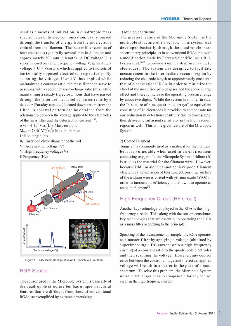
used as a means of ionization in quadrupole mass spectrometers. In electron ionization, gas is ionized through the transfer of energy from thermoelectrons emitted from the filament. The master filter consists of four electrodes (generally several mm in diameter and approximately 300 mm in length). A DC voltage U is superimposed on a high frequency voltage V, generating a voltage ±(U + Vcosωt), which is applied to two sets of horizontally opposed electrodes, respectively. By scanning the voltages U and V thus applied while maintaining a constant ratio, the mass filter can serve to pass ions with a specific mass-to-charge ratio (m/z) while maintaining a steady trajectory. Ions that have passed through the f ilter are measured as ion currents by a detector (Faraday cup, etc.) located downstream from the f ilter. A spectral pattern can be obtained from the relationship between the voltage applied to the electrodes of the mass filter and the detected ion current[1, 6].ΔM = 4×10⁹ Vz/(f2L2): Mass resolutionMmax = 7×10⁶ V/(f2r0
2): Maximum massL: Rod length (m)R0: Inscribed circle diameter of the rodVz: Acceleration voltage (V)V: High frequency voltage (V)f: Frequency (Hz)
Light Ions
X
Y
Z
Filament
Electrode Voltage (V)
Ligggghhht Ions
X
YYYY
Z
Filament
Electrode Voltage (V)
Ion Source
-(U+Vcosωt)
X
Y
Z
Multi Pole
+(U+Vcosωt) Heavy Ions
Detector
Light Ions
Ion
curr
ent (
A)
Figure 1 RGA: Basic Configuration and Principle of Operation
RGA Sensor
The sensor used in the Micropole System is basically of the quadrupole structure but has unique structural features that are different from those of conventional RGAs, as exemplified by extreme downsizing.
1) Multipole StructureThe greatest feature of the Micropole System is the multipole structure of its sensor. This system was developed basically through the quadrupole mass spectrometry principle, as in conventional RGAs, but with a modification made by Ferran Scientif ic Inc.’s R. J. Ferran et al.[2, 3] to provide a unique structure having 16 elect rodes. The system was designed to facilitate measurement in the intermediate vacuum region by reducing the electrode length to approximately one-tenth that of a conventional RGA in order to minimize the effect of the mean free path of gases and the space charge effect and thereby increase the operating pressure range by about two digits. While the system is smaller in size, the “structure of nine quadrupole arrays” or equivalent consisting of 16 electrodes is provided to compensate for any reduction in detection sensitivity due to downsizing, thus delivering sufficient sensitivity in the high vacuum region as well. This is the great feature of the Micropole System.
2) Coated FilamentTungsten is commonly used as a material for the filament, but it is vulnerable when used in an environment containing oxygen. In the Micropole System, iridium (Ir) is used as the material for the filament wire. However, because iridium alone cannot achieve good filament efficiency (the emission of thermoelectrons), the surface of the iridium wire is coated with yttrium oxide (Y2O3) in order to increase its efficiency and allow it to operate as an oxide filament[5].
High Frequency Circuit (RF circuit)
Another key technology employed in the RGA is the “high frequency circuit.” This, along with the sensor, constitutes key technologies that are essential to operating the RGA as a mass filter according to the principle.
Speaking of the measurement principle, the RGA operates as a master f ilter by applying a voltage (obtained by superimposing a DC current onto a high frequency current) at a constant ratio to the quadrupole electrodes and then scanning the voltage. However, any control error between the control voltage and the actual applied voltage will result in an error in the peak of a mass spectrum. To solve this problem, the Micropole System uses the actual gas peak to compensate for any control error in the high frequency circuit.
Feature Article
Development of a Small Residual Gas Analyzer Utilizing the Quadrupole Array Structure— Micropole System ~ QL Series ~ —
Hirokazu Kitaura
The Micropole System is one of the world’s smallest residual gas analyzers (RGAs). HORIBA STEC first obtained a license to an intellectual property right from Ferran Scientific Inc., (a U. S. company) and has developed this new system by adding the company’s own proprietary design elements. To control the “quality of a vacuum,” it isn’t sufficient to simply control the level of vacuum achieved with the use of an ion gauge or the like. It’s also important to monitor the vacuum quality, including the composition of gases that are present, by using a device such as an RGA. The RGA has quite a long history. By the 1950s its basis had already been established by Paul et al.[1] as quadrupole mass analysis technology. To this day, various manufacturers have continued to introduce RGAs developed by utilizing similar principles, although such RGAs are often employed only in high vacuum regions up to a maximum ambient pressure of 10-2 Pa in the operating environment. Under such circumstances, if RGAs that can be used in the intermediate vacuum region (for example, 10-1 Pa or above) become available, during certain processes it will not only be possible to measure the residual gases in a chamber (of manufacturing equipment) evacuated to a vacuum but also to conduct continuous measurement, even during the process. Based on the development discussed in this article, we have commercialized a product by carrying over the concept of an “RGA that can measure even in the intermediate vacuum region”[2, 3], as demonstrated in Ferran Scientific’s miniature RGAs, while improving quality and reliability and incorporating many user-friendly features, including “PC-free (without using a personal computer) usability,” that have not been available in previous RGAs.
Fe
at
ur
e
Ar
ti
cl
e
English Edition No.15 August 20116
Feature Article Development of a Small Residual Gas Analyzer Utilizing the Quadrupole Array Structure
Configuration
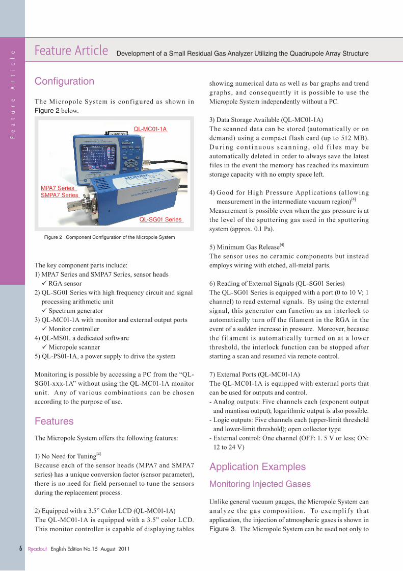
The Micropole System is conf igured as shown in Figure 2 below.
QL-MC01-1A
MPA7 SeriesSMPA7 Series
QL-SG01 Series
Figure 2 Component Configuration of the Micropole System
The key component parts include:1) MPA7 Series and SMPA7 Series, sensor heads RGA sensor
2) QL-SG01 Series with high frequency circuit and signal processing arithmetic unit Spectrum generator
3) QL-MC01-1A with monitor and external output ports Monitor controller
4) QL-MS01, a dedicated software Micropole scanner
5) QL-PS01-1A, a power supply to drive the system
Monitoring is possible by accessing a PC from the “QL-SG01-xxx-1A” without using the QL-MC01-1A monitor unit. Any of var ious combinations can be chosen according to the purpose of use.
Features
The Micropole System offers the following features:
1) No Need for Tuning[4]
Because each of the sensor heads (MPA7 and SMPA7 series) has a unique conversion factor (sensor parameter), there is no need for field personnel to tune the sensors during the replacement process.
2) Equipped with a 3.5” Color LCD (QL-MC01-1A)The QL-MC01-1A is equipped with a 3.5” color LCD. This monitor controller is capable of displaying tables
showing numerical data as well as bar graphs and trend graphs, and consequently it is possible to use the Micropole System independently without a PC.
3) Data Storage Available (QL-MC01-1A)The scanned data can be stored (automatically or on demand) using a compact f lash card (up to 512 MB). D u r i ng cont i nuou s s ca n n i ng , old f i le s m ay be automatically deleted in order to always save the latest files in the event the memory has reached its maximum storage capacity with no empty space left.
4) Good for High Pressure Applicat ions (allowing measurement in the intermediate vacuum region)[4]
Measurement is possible even when the gas pressure is at the level of the sputtering gas used in the sputtering system (approx. 0.1 Pa).
5) Minimum Gas Release[4]
The sensor uses no ceramic components but instead employs wiring with etched, all-metal parts.
6) Reading of External Signals (QL-SG01 Series)The QL-SG01 Series is equipped with a port (0 to 10 V; 1 channel) to read external signals. By using the external signal, this generator can function as an interlock to automatically turn off the filament in the RGA in the event of a sudden increase in pressure. Moreover, because the f ilament is automatically turned on at a lower threshold, the interlock function can be stopped after starting a scan and resumed via remote control.
7) External Ports (QL-MC01-1A)The QL-MC01-1A is equipped with external ports that can be used for outputs and control.- Analog outputs: Five channels each (exponent output
and mantissa output); logarithmic output is also possible.- Logic outputs: Five channels each (upper-limit threshold
and lower-limit threshold); open collector type- External control: One channel (OFF: 1. 5 V or less; ON:
12 to 24 V)
Application Examples
Monitoring Injected Gases
Unlike general vacuum gauges, the Micropole System can analyze the gas composit ion. To exempl ify that application, the injection of atmospheric gases is shown in Figure 3. The Micropole System can be used not only to

Feature Article Development of a Small Residual Gas Analyzer Utilizing the Quadrupole Array Structure
English Edition No.15 August 2011
Technical Reports
7
measure the pressure as a vacuum gauge but also to monitor the change in the ratio of gases, among other conditions.
2 12 22 32 42 52 62
amu
N2
O2
Ar
1.8E-01
1.5E-01
1.2E-01
9.0E-02
6.0E-02
3.0E-02
0.0E+00
Pre
ssur
e (P
a)
Figure 3 Atmospheric Injection Spectrum
Increase/Decrease in Amounts of Injected Gases
Figure 4 shows an example of monitoring how the partial pressures of gases are controlled in the trend graph. In the figure, the amount of O2 injected is reduced while the amount of N2 injected stays constant. The Micropole System can be used for leak detection for gas lines in use, for example by monitoring the amounts of residual N2 and O2 on a daily basis.
18amu
28amu
32amu
Total
N2 injection
Inject less O2.
Pre
ssur
e (P
a)
1.0E+00
1.0E- 01
1.0E- 02
1.0E- 03
1.0E- 04
1.0E- 05
1.0E- 06
Time (mm:ss)
00:00 02:53 05:46 08:38 11:31 14:24
Figure 4 Varying the Amount of Gas Injected
Measuring Residual Gases in Manufacturing Equipment
Residual moisture must be controlled if it will react with process gas, cause byproduct (s) and particles, and affect the quality of the film manufacturing process.
Equipment downtime can be minimized by monitoring H2O and other gases after monitoring the condition in the chamber and/or performing routine maintenance.
2 12 22 32 42 52 62
amu
N2
O2
H2O5.0E- 05
4.0E- 05
3.0E- 05
2.0E- 05
1.0E- 05
0.0E+00
Pre
ssur
e (P
a)
Figure 5 Initial Vacuum (Evacuation) State (high residual moisture)
For example, Figure 5 shows the in it ial vacuum (evacuation) state of a vacuum system that is. A spectrum like this one indicates that moisture generally remains in the vacuum system.
Controlling Partial Pressures as a Process Monitor
The Micropole System can also monitor gases released from the parts being used (degassing due to heating), making it possible to control the process quality on a daily basis.To exemplify that application, Figure 6 shows gases (mainly moisture in this example) released from a sample placed in a vacuum system.
0:00 2:24 4:48 7:12 9:36 12:00
18amu
28amu
32amu
40amu
44amu
Total
Moisture is
released due
to heating.
1.0E- 01
1.0E- 02
1.0E- 03
1.0E- 04
1.0E- 05
1.0E- 06
Pre
ssur
e (P
a)
Time (hh:mm)
Figure 6 Degassing Due to Sample Heating (moisture is released)

Fe
at
ur
e
Ar
ti
cl
e
English Edition No.15 August 20118
Feature Article Development of a Small Residual Gas Analyzer Utilizing the Quadrupole Array Structure
Conclusions
It has been 50 or more years since the quadrupole mass spectrometer technology was first established. While RGAs once had to be handled by technicians with professional skills, recently an increasing number of simpler, more user-friendly RGAs have been introduced to the market. The RGA we have developed follows that trend, and I hope it will be useful as a tool for controlling the “quality of a vacuum” on a daily basis in various fields.Measurement from the intermediate vacuum region (approx. 10-1 Pa), in particular, previously required the addition of a special differential pumping system with a pump for high vacuum applications. However, the RGA we’ve developed facil itates measurement without differential pumping and the Micropole System can therefore contribute to a significant reduction in cost.HORIBA STEC, with the proprietary mass spectrometer thus developed, aims to develop more new opportunities not just in the area of semiconductors but also in other business fields.Our future plans are to promote the development and improvement of RGAs so that RGAs will serve as key components of Advanced Process Control (APC) designed with the objective of performing the integrated control of increasingly complex semiconductor processes, in addition to gas injection technology with the cutting-edge mass f low controllers (MFC) in which we’ve built our expertise over the years. Additionally, we plan to offer products at more reasonable prices through a program we h ave d e ve lo p e d a s p a r t o f o u r e f fo r t t o m a ke improvements jointly with our users in the area of MFC.
References
[1] P. H. Dawson, Quadrupole Mass Spectrometry and Its Applications, American Vacuum Society Classics; AIP PRESS (1995).
[2] R. J. Ferran and S. Boumsellek, High-pressure Effects in Miniature Arrays of Quadrupole Analyzers for Residual Gas Analysis from 10-9 to 10-2 Torr; Journal of Vacuum Science and Technology, A 14 (3), May/June 1996.
[3] S. Boumsel lek and R. J. Fer ran, Trade-offs in Miniature Quadrupole Designs; Journal of American Vacuum Society, Mass Spectrom 2001, 12, 633-640.
[4] Toru Ikeda, Miniature Residual Gas Analyzer, Pressure Master RGA Series; Read Out No. 28, March 2004.
[5] Takagi, Electron/Ion Beam Engineering; The Institute of Electrical Engineers of Japan, Ohmsha, Ltd., 1995.
[6] J. H. Gross, Mass Spectrometry; Springer Japan, 2007.
Feature Article Development of a Small Residual Gas Analyzer Utilizing the Quadrupole Array Structure
English Edition No.15 August 2011
Technical Reports
9
Hirokazu KitauraVEGA Project, Development OperationsHORIBA STEC Inc.