Read this user manual carefully before running KF4A SWIFT ... user manual_eng.pdf · Read this user...
103
Optical Fiber Arc Fusion Splicer Read this user manual carefully before running KF4A SWIFT KF4A WWW.ILSINTECH.COM USER MANUAL
Transcript of Read this user manual carefully before running KF4A SWIFT ... user manual_eng.pdf · Read this user...

Optical Fiber Arc Fusion Splicer Read this user manual carefully before running KF4A
SWIFT KF4A
WWW.ILSINTECH.COM
USER MANUAL

This device complies with Part 15 of the FCC Rules. Operation is subject to the following
two conditions: (1) This device may not cause harmful interference, and (2) this device must
accept any interference received, including interference that may cause undesired
operation.
Telephone 042 671 5607~8 Homepage www.ilsintech.com E-mail [email protected]
Device Type Notification
A Class Device
(Broadcasting and
communication
device, commercial
use)
Users need to understand that this device(A Class) has
obtained EMI(Electromagnetic compatibility) and been
designed to be used in places other than home.
1
Contents
SAFETY INSTRUCTION 3
PRODUCT SPECIFICATIONS AND COMPONENT 7
2.1 Product specifications 7
2.2 Product package 8
PRODUCT OUTLINE 10
3.1 Function buttons 10
3.2 Component name 11
INSTRUCTIONS FOR USE 13
4.1 Power supply 13
4.2 How to turn the power ON/OFF 15
4.3 Fiber cleaning 16
4.4 Inserting fiber to protecting sleeve 16
4.5 Fiber stripping 17
4.6 Fiber cleaning 20
4.7 Fiber cleaving 21
4.8 KF4A Sleeve-Heater 26
4.9 Splice procedure 29
4.10 Removing the spliced fiber 30
4.11 Heating protection sleeve 30
4.12 Use of Work Belt 31
MAINTENANCE OF SPLICE QUALITY 32
5.1 Cleaning and Inspection before splice 32
5.2 Regular inspection and cleaning 34
MENU 36
6.1 Splice 47
6.2 Heater 55

2
6.3 Stripping 60
6.4 Splice result 64
6.5 Option 66
6.6 Optical module 70
6.7 Calibration 72
6.8 Electrodes 77
6.9 Setting 81
6.10 Information 85
ERROR MESSAGE 88
7.1 Too Dirty Fiber 88
7.2 Replace Fiber. 88
7.4 Fiber Over Angle 89
7.5 Loss Limit Over. 90
7.6 Fiber Thin Error 90
7.7 Fiber Thick Error 90
7.8 Bubble error 91
7.9 Cleaved Surface Error 91
SPLICING PROBLEM SOLVING 92
8.1 When loss is high 92
8.2 Abnormal splicing operation 93
PROBLEM OCCURRENCE AND QUESTION 94
9.1 Power 94
9.2 Splice 95
9.4 Others 97
WARRANTY AND REPAIR 99
10.1 Information necessary for repair 99
10.2 Transportation 100
3
Safety instruction Swift KF4A is designed to be used conveniently on both indoor and outdoor work sites. Its use is easy and simple but make sure to read this instructions prior to prevent accidents and malfunctions before using Swift KF4A. This user guide provides information necessary for safe operation.
Ilsintech does not take any responsibility for the equipment’s damage and personal or physical loss incurred due to improper use or alteration.
When any of the following occurs during the use, turn off the power immediately and contact to Ilsintech. Smoke, disgusting smell, noise or abnormal overheating. When a foreign substance or liquid falls into the equipment When the splicer falls down or it is damaged
Regarding AC power cord, use the one provided with Swift KF4A. If a power cord other than provided is used, it may incur fire, electrical shock or injury.
Do not touch the Electrodes when power is on. High voltage and high temperature generated from Electrodes may incur serious shock or burn.
Connect the provided AC power cord to a battery. Check if there is any foreign substance on the terminal before connecting it to the AC power socket.
Incomplete splice may incur smoke, electric shock, fire, damage of equipment, serious injury and even death.
Keep this users guide with the product at all times.
Warnings

4
Use proper power voltage. AC power for the adapter is AC100-240V, 50~60Hz. Test the AC power before use. When output voltage of AC power is high or abnormal frequency is generated, the product is damaged and serious injury or even death may be incurred to the user. AC output voltage should be measured using circuit tester before connecting AC power cable and regular inspection should also be conducted. Do not pull AC power cord with excessive force, apply heat or transform it. When a damaged power cord is used, it may incur fire or injury. Use 3-plug AC power cord and do not ever use 2-plug power cord, cable or plug.
Do not touch AC plug, AC power cord or splicer with wet hands. It may incur electric shock.
Do not disassemble AC adapter, battery or Swift KF4A. Deformation may incur fire, electrical shock or injury. Refer to the following when using the battery. When an improper battery which is not provided by Ilsintech is used, it may
incur smoke, damage of equipment, burn, injury or even death. Do not dispose the battery into fire. Do not charge the battery near flame. Do not give an excessive shock to the battery. When the battery does not completely charge in 2 hours or the green LED is
not turned on, stop charging immediately and contact Ilsintech. Do not put anything on AC adapter while charging.
Use exclusively the AC adapter provided. Do not use another AC power cord or battery. Excessive current may incur equipment damage or injury.
Do not use Swift KF4A where there is harmful gas or flammable liquid. Explosion or fire may be incurred due to electrical arc.
Warnings
5
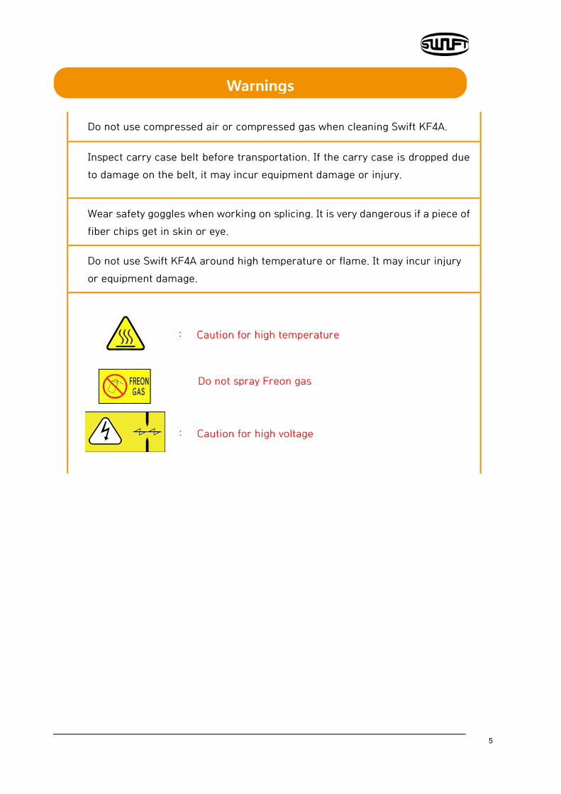
Do not use compressed air or compressed gas when cleaning Swift KF4A.
Inspect carry case belt before transportation. If the carry case is dropped due to damage on the belt, it may incur equipment damage or injury.
Wear safety goggles when working on splicing. It is very dangerous if a piece of fiber chips get in skin or eye.
Do not use Swift KF4A around high temperature or flame. It may incur injury or equipment damage.
: Caution for high temperature
Do not spray Freon gas
: Caution for high voltage
Warnings
6
Do not touch sleeve heater or protecting sleeve while sleeve heater is operating or right after heating is completed. It may incur injury due to high temperature.
Do not put Swift KF4A in an unstable place. When the equipment is dropped, it incurs injury or equipment damage.
Swift KF4A should be accurately adjusted and treated in alignment. Do not give it a strong shock, either. Use a carry case to carry or to keep Swift KF4A. The carry case keeps the equipment from humidity, vibration and shock during storage and transportation and prevents possible damage to KF4A.
Replace the Electrodes in timely manner referring to the following. Designated electrodes should be used. Place new Electrodes to the right position. Replace the Electrodes in pairs.
Abnormal arc is incurred when not following the aforementioned caution. It may incur equipment damage or an abnormal splice.
Do not use any chemical other than ethyl alcohol (96% or higher) to clean lens, V-Groove, LCD monitor and main body. Using other chemicals may incur deformation, discoloration or deteriorated performance.
Do not keep the equipment in any environment where the high temperature or high humidity prevails. It may incur equipment damage.
Swift KF4A should be inspected by a qualified expert, or it may incur fire or electric shock. Discuss with Ilsintech to use the service.
Cautions

7
Product specifications and component 2.1 Product specifications
Item Description
Fiber alignment IPAAS clad alignment method
Applicable fibers 0.25mm, 0.9mm, 2.0mm, 3.0mm Indoor cable
Number of fiber core applicable
Single
Fiber diameter Clad diameter: 125 ㎛, Coating diameter: 150 ㎛~3mm
Cleaved length 5.0mm~16mm
Splice mode Splice mode: 300, Heater mode: 100
Splice loss SM: 0.02dB, MM: 0.01dB, DS: 0.04dB, NZDS: 0.04dB
Reflection loss > 60dB
Splice time About 7 seconds (Quick mode)
Sleeve heating time 9 seconds (IS-45 sleeve, IS-45 mode), 13 seconds (IS-60 sleeve, IS-60 mode)
Applicable protecting sleeve
40mm, 60mm, 32mm or 28mm (For SOC)
Data storage Internal memory capable of saving 5,000 times (Saving 5,000 images)
Tension test 1.96N ~ 2.25N
Size 132(W) x 212(L) x 73(H)mm
Weight 1.5kg
Fiber magnification X/Y : 110X, Max 220X
8
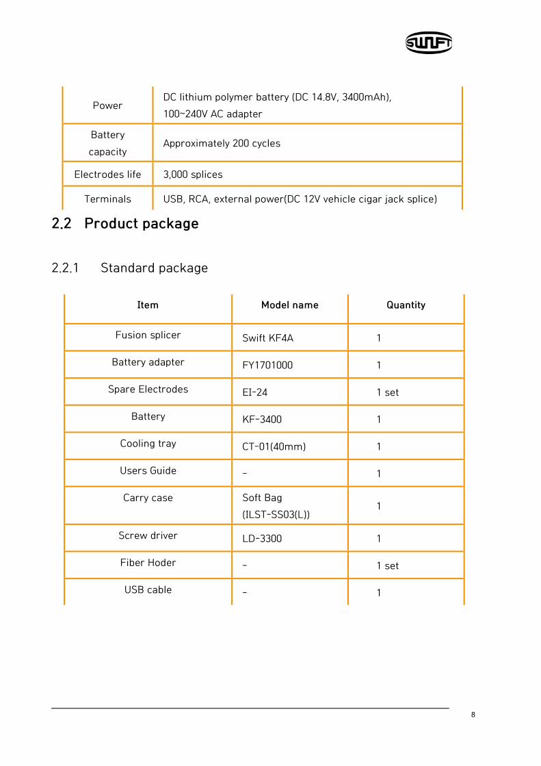
Power DC lithium polymer battery (DC 14.8V, 3400mAh), 100~240V AC adapter
Battery capacity
Approximately 200 cycles
Electrodes life 3,000 splices
Terminals USB, RCA, external power(DC 12V vehicle cigar jack splice)
2.2 Product package 2.2.1 Standard package
Item Model name Quantity
Fusion splicer Swift KF4A 1
Battery adapter FY1701000 1
Spare Electrodes EI-24 1 set
Battery KF-3400 1
Cooling tray CT-01(40mm) 1
Users Guide - 1
Carry case Soft Bag (ILST-SS03(L))
1
Screw driver LD-3300 1
Fiber Hoder - 1 set
USB cable - 1
9
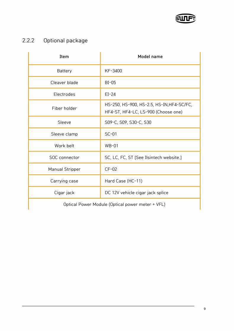
2.2.2 Optional package
Item Model name
Battery KF-3400
Cleaver blade BI-05
Electrodes EI-24
Fiber holder HS-250, HS-900, HS-2.5, HS-IN,HF4-SC/FC, HF4-ST, HF4-LC, LS-900 (Choose one)
Sleeve S09-C, S09, S30-C, S30
Sleeve clamp SC-01
Work belt WB-01
SOC connector SC, LC, FC, ST [See Ilsintech website.]
Manual Stripper CF-02
Carrying case Hard Case (HC-11)
Cigar jack DC 12V vehicle cigar jack splice
Optical Power Module (Optical power meter + VFL)
10
Product outline
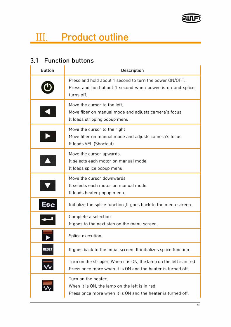
3.1 Function buttons Button Description
Press and hold about 1 second to turn the power ON/OFF. Press and hold about 1 second when power is on and splicer turns off.
Move the cursor to the left. Move fiber on manual mode and adjusts camera’s focus. It loads stripping popup menu.
Move the cursor to the right Move fiber on manual mode and adjusts camera’s focus. It loads VFL (Shortcut)
Move the cursor upwards. It selects each motor on manual mode. It loads splice popup menu.
Move the cursor downwards It selects each motor on manual mode. It loads heater popup menu.
Initialize the splice function.,It goes back to the menu screen.
Complete a selection It goes to the next step on the menu screen.
Splice execution.
It goes back to the initial screen. It initializes splice function.
Turn on the stripper.,When it is ON, the lamp on the left is in red. Press once more when it is ON and the heater is turned off.
Turn on the heater. When it is ON, the lamp on the left is in red. Press once more when it is ON and the heater is turned off.

11
3.2 Component name
Wind cover
Battery
Monitor
Sleeve heater Stripper
Cleaver
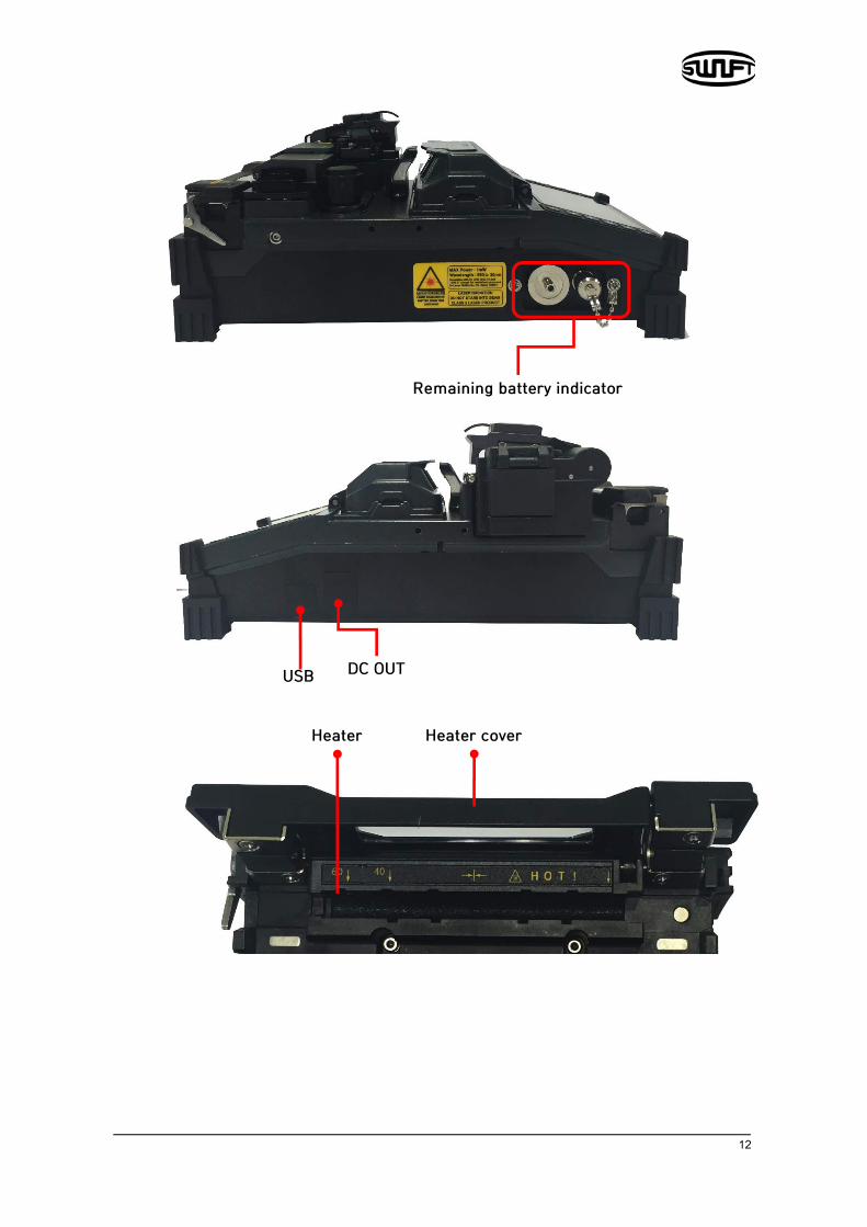
12
Remaining battery indicator
Heater cover Heater
DC OUT USB

13
Instructions for use The following is the initial screen of Swift KF4A. For accurate splice result, splice mode, stripping mode and heater mode should be properly selected. Basic information on Swift KF4A is displayed on the initial screen. Check whether the proper mode is selected before splice.
4.1 Power supply Battery pack is built in at the battery chamber. Loosen the bolts at the bottom cover and exchange battery. Please be cautious when you detach the battery from the chamber.
4.1.1 Built in battery
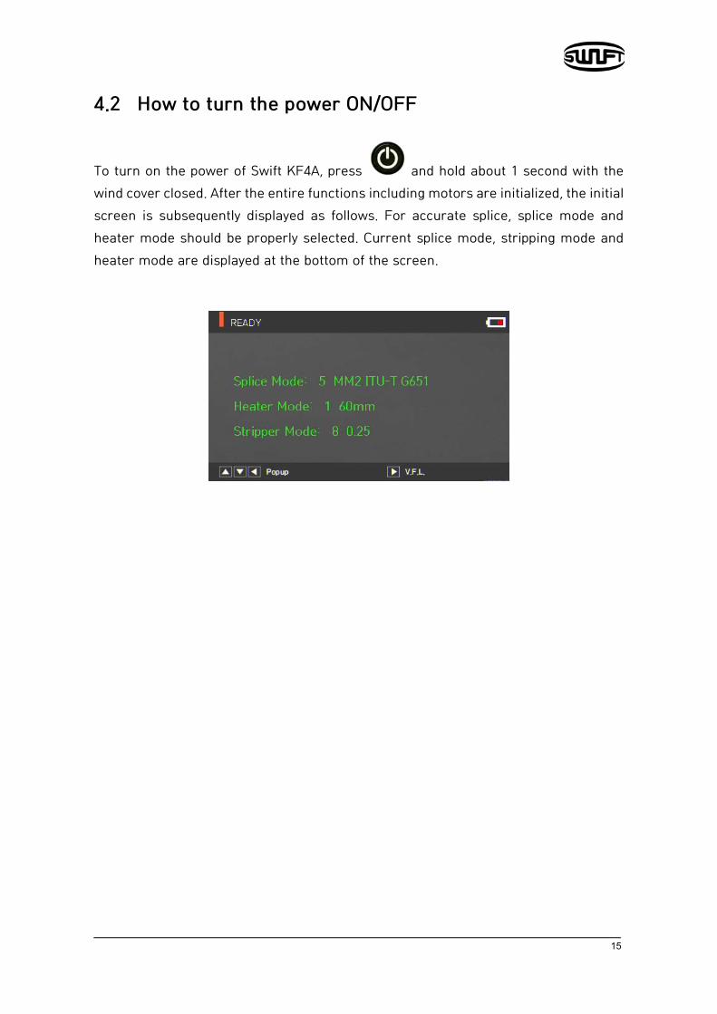
Battery status indicator
Current splice mode
Current heater mode
Current stripping mode

14
4.1.2 Battery charging Make sure you check the voltage, frequency and then the DC cable of AC/DC adaptor connects to the DC jack of the battery before charging the battery When the battery is fully charged, LED will turn green and power is disconnected, activating protection circuit to avoid overcharge. The power is turned back on as the battery needs to be charged and charging resumes when the DC cable of adaptor is connected to the DC jack of the battery.
15
4.2 How to turn the power ON/OFF
To turn on the power of Swift KF4A, press and hold about 1 second with the wind cover closed. After the entire functions including motors are initialized, the initial screen is subsequently displayed as follows. For accurate splice, splice mode and heater mode should be properly selected. Current splice mode, stripping mode and heater mode are displayed at the bottom of the screen.

16
4.3 Fiber cleaning
Wipe fiber clean with soft cloth or cotton moistened with alcohol. Fine dust on the surface of the fiber may increase loss after splice and incur damage on the fiber after heating.
4.4 Inserting fiber to protecting sleeve
Put fiber into the protective sleeve.

17
4.5 Fiber stripping
Automatic stripper of KF4A automatically performs accurate stripping with single fiber. This thermal stripper does not incur cracks on stripped fiber with superb tensile force. Stripping length of the fiber can be up to 28.0mm. To keep the equipment’s optimal performance, thoroughly understanding and memorizing the instructions is extremely important for proper use. Also, wipe the fiber clean with soft cloth or cotton moistened with alcohol.
Be careful not to soak this equipment in any kind of liquid.
Keep it clean all the time as it is vulnerable to humidity and dust. Keep and use it at room temperature as deformation can be happened due to high temperatures. Be careful to use the product as a breakdown can be happened due to vibration and shock. When cleaning the product, do not use any organic solvent such as acetone other than alcohol on any of the rubber parts. Fiber diameter 125㎛
Cable diameter 250㎛, 900㎛
Cleaved length Max 28.0 ㎜
Heating time 0 ~ 15 sec
Temperature range 60 °C ~ 150 °C
Tensile force after stripping 4kgf
18
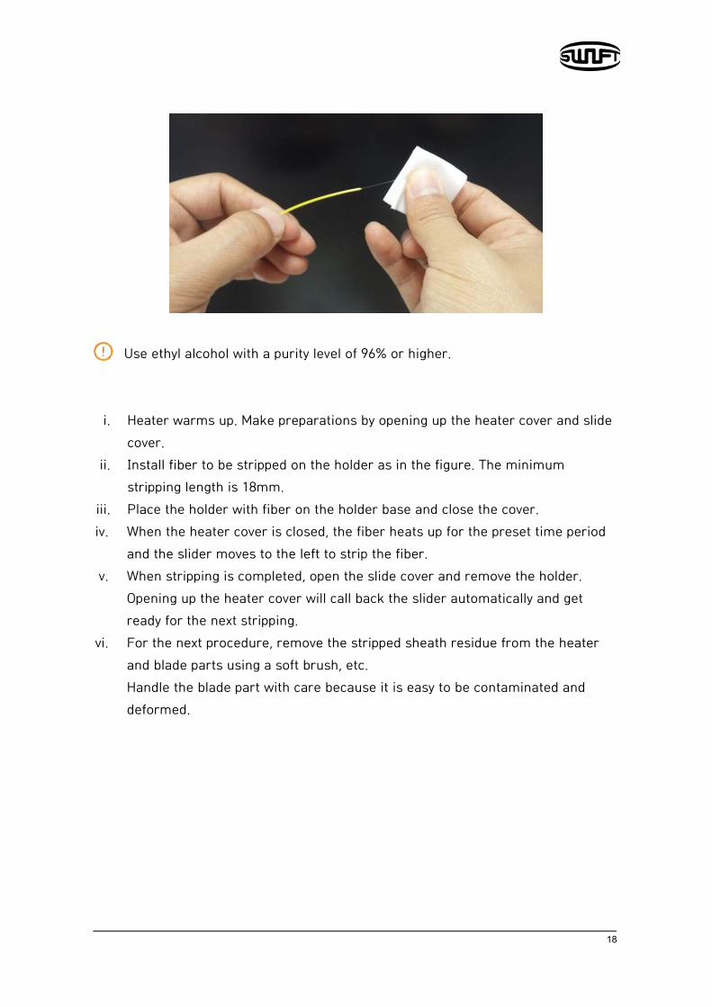
Use ethyl alcohol with a purity level of 96% or higher.
i. Heater warms up. Make preparations by opening up the heater cover and slide cover.
ii. Install fiber to be stripped on the holder as in the figure. The minimum stripping length is 18mm.
iii. Place the holder with fiber on the holder base and close the cover. iv. When the heater cover is closed, the fiber heats up for the preset time period
and the slider moves to the left to strip the fiber. v. When stripping is completed, open the slide cover and remove the holder.
Opening up the heater cover will call back the slider automatically and get ready for the next stripping.
vi. For the next procedure, remove the stripped sheath residue from the heater and blade parts using a soft brush, etc. Handle the blade part with care because it is easy to be contaminated and deformed.
19
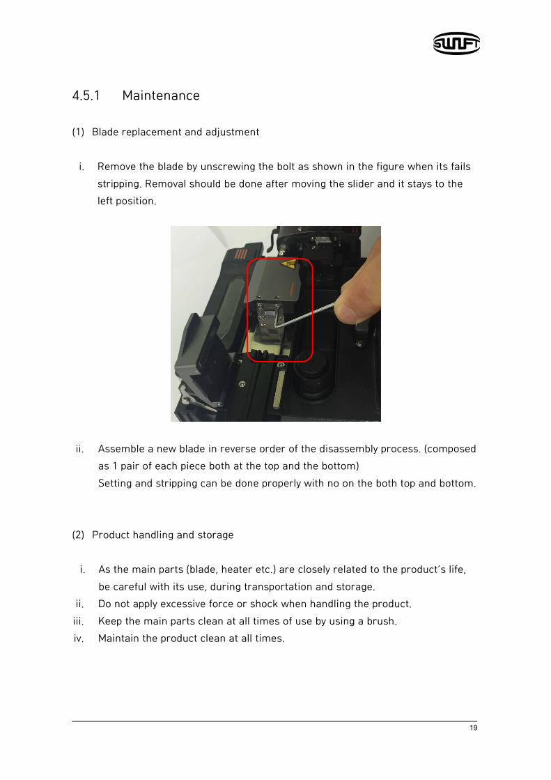
4.5.1 Maintenance (1) Blade replacement and adjustment
i. Remove the blade by unscrewing the bolt as shown in the figure when its fails stripping. Removal should be done after moving the slider and it stays to the left position.
ii. Assemble a new blade in reverse order of the disassembly process. (composed
as 1 pair of each piece both at the top and the bottom) Setting and stripping can be done properly with no on the both top and bottom.
(2) Product handling and storage
i. As the main parts (blade, heater etc.) are closely related to the product’s life, be careful with its use, during transportation and storage.
ii. Do not apply excessive force or shock when handling the product. iii. Keep the main parts clean at all times of use by using a brush. iv. Maintain the product clean at all times.

20
4.6 Fiber cleaning
The alcohol dispenser of KF4A releases a fixed cleaning agent for fiber cleaning.
Be careful not to soak this equipment in any amount of liquid
Keep it clean at all times as it is vulnerable to humidity and dust. Keep and use it at room temperature as it can become deformed due to high temperature. Be careful when using this product as it may break down due to vibration and shock. When cleaning the product, do not use any organic solvent such as acetone other than alcohol on any of the rubber parts.
i. When cleaning, arc the cleaning agent by pressing 2~3 times with cleaning cotton swab. Arc the cleaning agent while covering the entire outlet with cotton to prevent it from spraying outwards.
ii. When the cleaning agent is no longer pumped, refill it by opening the cap. iii. Use MCC-POC03M as the exclusive cleaning agent.
Cleaner
21
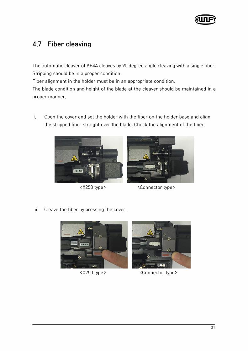
4.7 Fiber cleaving
The automatic cleaver of KF4A cleaves by 90 degree angle cleaving with a single fiber. Stripping should be in a proper condition. Fiber alignment in the holder must be in an appropriate condition. The blade condition and height of the blade at the cleaver should be maintained in a proper manner.
i. Open the cover and set the holder with the fiber on the holder base and align the stripped fiber straight over the blade, Check the alignment of the fiber.
<Φ250 type> <Connector type>
ii. Cleave the fiber by pressing the cover.
<Φ250 type> <Connector type>
22
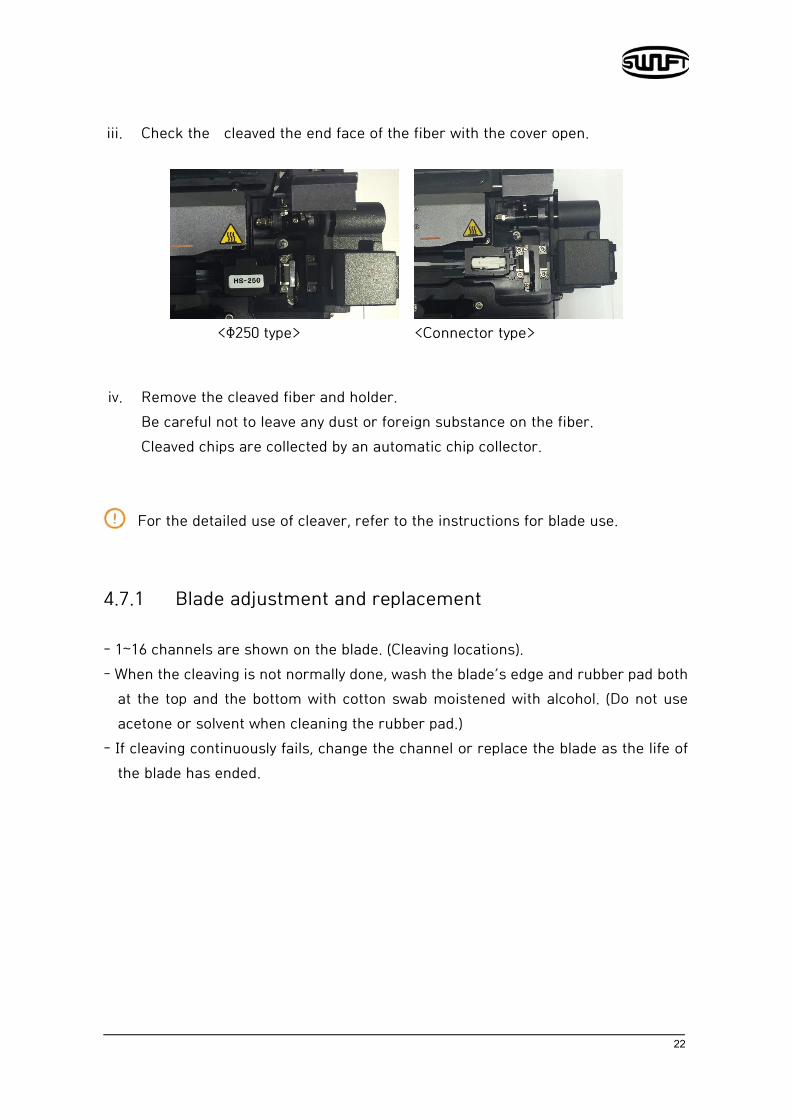
iii. Check the cleaved the end face of the fiber with the cover open.
<Φ250 type> <Connector type>
iv. Remove the cleaved fiber and holder.
Be careful not to leave any dust or foreign substance on the fiber. Cleaved chips are collected by an automatic chip collector. For the detailed use of cleaver, refer to the instructions for blade use.
4.7.1 Blade adjustment and replacement
- 1~16 channels are shown on the blade. (Cleaving locations). - When the cleaving is not normally done, wash the blade’s edge and rubber pad both
at the top and the bottom with cotton swab moistened with alcohol. (Do not use acetone or solvent when cleaning the rubber pad.)
- If cleaving continuously fails, change the channel or replace the blade as the life of the blade has ended.
23
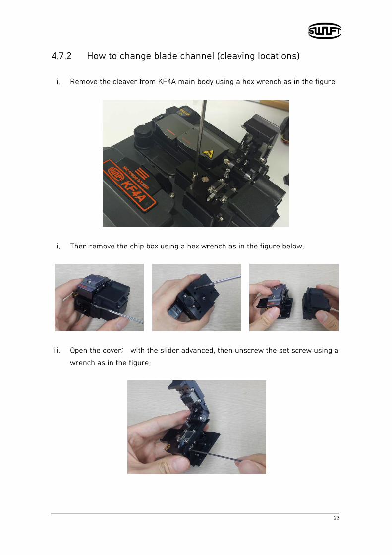
4.7.2 How to change blade channel (cleaving locations)
i. Remove the cleaver from KF4A main body using a hex wrench as in the figure.
ii. Then remove the chip box using a hex wrench as in the figure below.
iii. Open the cover; with the slider advanced, then unscrew the set screw using a
wrench as in the figure.
24
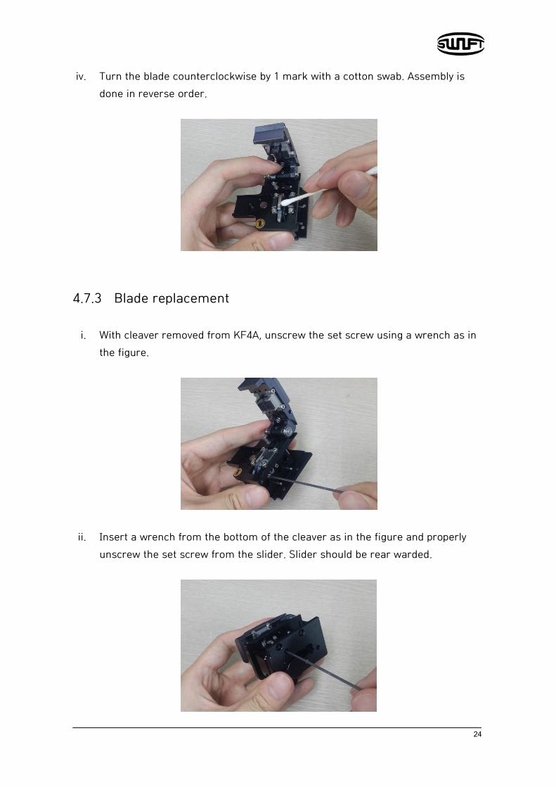
iv. Turn the blade counterclockwise by 1 mark with a cotton swab. Assembly is done in reverse order.
4.7.3 Blade replacement
i. With cleaver removed from KF4A, unscrew the set screw using a wrench as in the figure.
ii. Insert a wrench from the bottom of the cleaver as in the figure and properly
unscrew the set screw from the slider. Slider should be rear warded.

25
iii. Turn the wrench bolt; put it in Cam Pin and then remove it from the slider by
pulling with a tweezers, etc.
iv. Pay special attention in order to prevent blade damage while replacing it.
Assembly is done in reverse order of disassemble and the set screw should be firmly tightened.
4.7.4 Blade height adjustment
i. Insert a wrench in the bottom of cleaver as in the figure and properly unscrew the set screw of slider. Slider should be back warded.
ii. Turn the Cam Pin with flat - headed screwdriver to adjust the blade’s height.
Turning clockwise : Blade going up Turning counterclockwise : Blade is going down

26
When the blade is adjusted to the proper height, tighten the set screw of slide. The height adjustment of the blade is closely related to cleaving quality . Make sure you perform height adjustment with BHS-01, sold separately.
Please contact customer service for the information and availability of BHS-01.
4.8 KF4A Sleeve-Heater
The sleeve heater of KF4A reinforces spliced point of the single fiber. The quality of fusion splicing on the fiber should be good. Fiber that sleeve tube is inserted to heater should be properly aligned and installed. Heater cover should be closed while heater is on.
Cable diameter Φ250㎛, Φ 900㎛, Φ 2.0㎜~ Φ 3.0㎜
Sleeve length standard 32mm
Sleeving time 20~35 sec
Temperature range 130°C ~ 200 °C
i. Open up the heater cover to start.
ii. Place the sleeve tube on the spliced point. Make sure center of the sleeve

27
tube covers the spliced point. Load the fiber into the heater. For the fusion splice on connectors, load it into the right end of the heater and press the sleeve tube into the heater as tight as possible.

28
iii. After settling the fiber, turn on the heater by pressing . . (Heating time 20sec)
iv. Remove the sleeve protected fiber by opening the cover when the cooling is completed.
The better positioning of the fibers will shorten heating time

29
4.9 Splice procedureThe status and cleaved quality of the fiber can be
monitored by using an image processing system by Swift KF4A. For better splice result, however, visual inspection is required also.
In auto mode, the splice procedure begins automatically as the wind cover is closed.
i. Fibers installed on the splicer advance toward each other and stop. The fibers align once cleaning arc is done. After that, the splicer checks cutting the cleaved angle of each fiber, the shape of the end faces, contaminations and so on. When the measured cleaved angle is bigger than the preset value or damage is detected on fiber, error message is displayed on the screen. And splice procedure stops as well. Even if there is no error message displayed, visual inspection on the monitor screen is always recommended.
ii. Fibers are aligned cladding to cladding after inspection. Deviation on clad axis can be displayed on screen.
iii. After alignment completes, arcing is conducted to splice fibers. iv. After splicing is completed, the estimated value of loss is displayed on the
screen. The estimated value of splice loss is subject to various factors related to error. These factors related to an error affect the estimation and calculation of estimated loss value as well. Calculation of estimated loss is based on factors such as MFD. When estimated loss value exceeds the preset value and error message is displayed on the screen. The error message is also displayed when the spliced fibers are too thick or thin or when bubbles are generated on the spliced point. If the splice result shown on the screen is not considered good enough, it is recommended to conduct splicing again
v. The splice result is saved as follows. When splice completes, splice result is automatically saved.

30
4.10 Removing the spliced fiber
i. Open the cover of the sleeve heater. ii. Open the wind cover. iii. Hold the fiber on the left and open the clamp on the left. iv. Open the fiber clamp on the right. v. Hold both sides of spliced fiber and separate the fiber from Swift KF4A
with care.
4.11 Heating protection sleeve
i. Move spliced point to the center of the protecting sleeve. Place the protected
pin in the sleeve with face down. ii. Place the protecting sleeve at the center of sleeve heater.
iii. Hold and put down the both fibers as shown in the figure then the heater cover will automatically close.
iv. Heating starts by pressing . v. LED is turned off when heating is completed. vi. Open the heater cover and take out the fiber. Do not touch the protecting
sleeve or heater at any point during or right after heating. vii. Conduct a final inspection on whether there are bubbles, fragments or any
dust on the sleeve.

31
4.12 Use of Work Belt
The work belt of Swift KF4A is a type of auxiliary equipment that combines with its main body to facilitate working at a manhole, utility pole, etc.
4.12.4 Use of Work Belt
Work belt components

32
Maintenance of splice quality
5.1 Cleaning and Inspection before splice
5.1.1 V-Groove cleaning When the inside of V-Groove is contaminated, splice quality may deteriorate. Thus, it is important to regularly inspect and frequently clean the V-Groove as follows.
i. Open the wind cover. ii. Clean the V-Groove using a cotton swab moisten by alcohol and any proper
cleaning agents. Remove the remaining alcohol from the V-Groove using a clean and lint free dry cotton swab.
iii. When a foreign substance is not removed with cotton swab, clean it with the tip of a cleaved fiber and then repeat the step above.
33
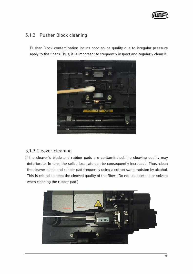
5.1.2 Pusher Block cleaning
Pusher Block contamination incurs poor splice quality due to irregular pressure apply to the fibers Thus, it is important to frequently inspect and regularly clean it.
5.1.3 Cleaver cleaning If the cleaver’s blade and rubber pads are contaminated, the cleaving quality may deteriorate. In turn, the splice loss rate can be consequently increased. Thus, clean the cleaver blade and rubber pad frequently using a cotton swab moisten by alcohol. This is critical to keep the cleaved quality of the fiber. (Do not use acetone or solvent when cleaning the rubber pad.)

34
5.2 Regular inspection and cleaning To ensure splicing quality, regular inspection and cleaning is required.
5.2.1 Object lens cleaning Contamination on object lens’ surface disturbs the identification of fiber core location and consequently incurs high splice loss. Thus, 2 object lenses should be kept clean at all times. If accumulated dust stays for a prolonged period, it may be difficult to remove. Therefore, clean the lens frequently as follows.
i. Turn the power off before cleaning the object lens. ii. Separate the Electrodes. iii. Clean it using a soft cotton swab moisten with alcohol in circular motion
from the center as in the figure below. Dry out alcohol remaining on object lens’ surface using a clean, lint free dry cotton swab
iv. Surface of object lens should be clean without any line or stain. v. Reassemble the Electrodes.
vi. Turn the power on; check whether there is any line or stain on the monitor and; conduct a self-diagnosis.
35
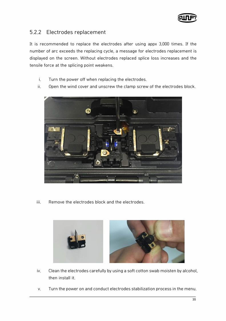
5.2.2 Electrodes replacement
It is recommended to replace the electrodes after using appx 3,000 times. If the number of arc exceeds the replacing cycle, a message for electrodes replacement is displayed on the screen. Without electrodes replaced splice loss increases and the tensile force at the splicing point weakens.
i. Turn the power off when replacing the electrodes. ii. Open the wind cover and unscrew the clamp screw of the electrodes block.
iii. Remove the electrodes block and the electrodes.
iv. Clean the electrodes carefully by using a soft cotton swab moisten by alcohol, then install it.
v. Turn the power on and conduct electrodes stabilization process in the menu.

36
Menu
The main menu has 10 submenus. Press to load main menu. The 10
submenus can be selected by using and or by directly pressing the screen. The main menu screen is as follows.
Splicing Delete: Deletes splice mode. Replace: Selects and replaces a certain splice mode within the database. Add: Selects and adds a certain splice mode within the database. Edit: Edits set values of splice mode. Select: Selects a splice mode to run. Close: Closes the menu window.
Heater Delete: Deletes heater mode. Replace: Selects and replaces a certain heater mode within the
database. Add: Selects and adds a certain heater mode within the database. Edit: Edits set values of in the heater mode. Select: Selects a heater mode to run. Close: Closes menu window.

37
Stripping Delete: Deletes stripping mode. Replace: Selects and replaces a certain stripping mode within the
database. Add: Selects and adds a certain stripping mode within the database. Edit: Edits set values of for the stripping mode.
Splice result Splice result display: Displays splice result and image. Delete splice result: Deletes all data.
Option Splice operation initial setting: Auto, Pause, Auto heater Menu lock: Menu lock setting Password: Password setting upon locking
Optical module Optical Power Meter: Checks up optical power meter information V.F.L.: Activate visual fault locator.
Calibration Arc calibration: Adjust arc calibration intensity. Diagnostic test: Diagnoses equipment state. Motor operation: Operates motor manually. Motor calibration: Initializes motor’s speed and location.
Electrodes Electrodes stabilizing: Conducts electrodes stabilizing. Electrodes caution: Sets the number of uses to inform when to replace
the electrodes. Electrodes replacement: Explains how to replace the electrodes. Number of using electrodes: Displays the electrodes use count.

38
Setting Language: Selects a language. Time: Sets the present time. Sleep: Sets sleep mode. Sound: Adjusts intensity of the buzzer sound. LCD brightness: Adjusts the brightness of the screen.
Information Maintenance: Displays maintenance schedule. Sensor: Indicates temperature, pressure. Version: Shows the current version of product. Help: Consists of the following.
- Name of each part - Cleaning and Inspection - Cautions - Contact Ilsintech

39
Popup Menu
The purpose of the popup menu is to facilitate easy and quick access to the splice mode and heater mode. User can access the popup menu in various ways.
[Displaying popup menu] i. Splice popup menu can be displayed the current splice mode by pressing
on initial screen.
ii. Heater popup menu can be displayed the current heater mode by pressing
on initial screen.

40
iii. Stripper popup menu can be displayed the current stripping mode by pressing
on initial screen.
[Splice popup menu] Adding splice mode
i. Display splice popup menu by pressing on initial screen.
ii. Select an empty slot by pressing and then
press .

41
iii. Select a splice mode to add up to the empty slot.
42
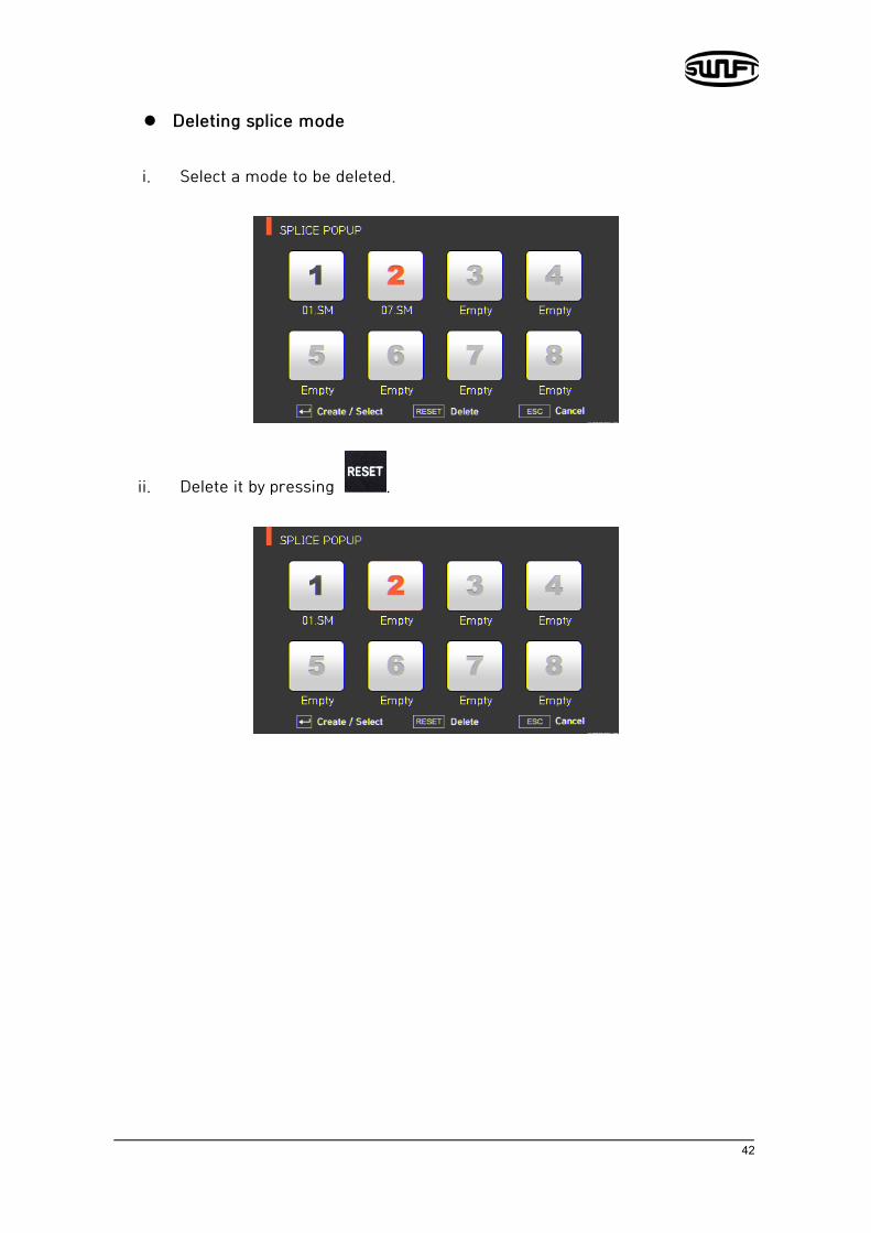
Deleting splice mode i. Select a mode to be deleted.
ii. Delete it by pressing .

43
[Heater popup menu] Adding heater mode
i. Display heater popup menu by pressing on initial screen.
i. Select an empty slot by pressing and then
press .
ii. Select a heater mode to add up to the empty slot.

44
Deleting heater mode
i. Select a mode to be deleted.
i. Delete it by pressing .
45
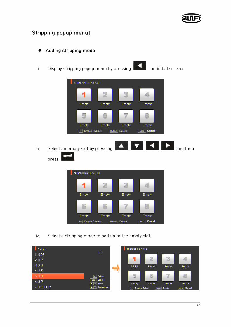
[Stripping popup menu] Adding stripping mode
iii. Display stripping popup menu by pressing on initial screen.
ii. Select an empty slot by pressing and then
press .
iv. Select a stripping mode to add up to the empty slot.

46
Deleting stripping mode
ii. Select a mode to be deleted.
ii. Delete it by pressing .
47
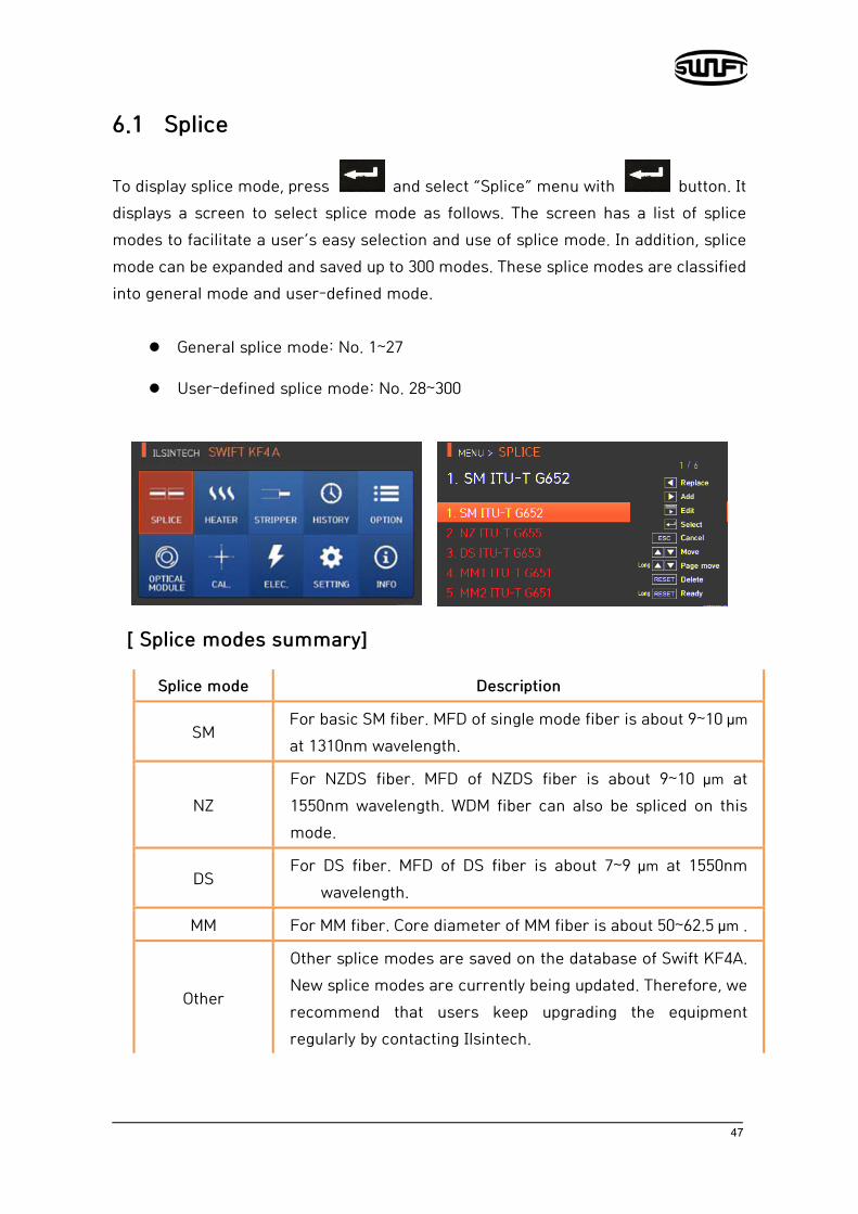
6.1 Splice
To display splice mode, press and select “Splice” menu with button. It displays a screen to select splice mode as follows. The screen has a list of splice modes to facilitate a user’s easy selection and use of splice mode. In addition, splice mode can be expanded and saved up to 300 modes. These splice modes are classified into general mode and user-defined mode.
General splice mode: No. 1~27
User-defined splice mode: No. 28~300
[ Splice modes summary]
Splice mode Description
SM For basic SM fiber. MFD of single mode fiber is about 9~10 µm at 1310nm wavelength.
NZ For NZDS fiber. MFD of NZDS fiber is about 9~10 µm at 1550nm wavelength. WDM fiber can also be spliced on this mode.
DS For DS fiber. MFD of DS fiber is about 7~9 µm at 1550nm
wavelength.
MM For MM fiber. Core diameter of MM fiber is about 50~62.5 µm .
Other
Other splice modes are saved on the database of Swift KF4A. New splice modes are currently being updated. Therefore, we recommend that users keep upgrading the equipment regularly by contacting Ilsintech.

48
6.1.1 Deletion
First, select a splice mode by pressing . And then press and the selected mode is deleted. General modes no. 1~27 are unable to be deleted.
6.1.2 Replacement
Select a splice mode to replace and press , and splice modes saved on the database are displayed on the screen. Select a splice mode to replace and press
, and the mode is replaced with the new mode.
General modes no. 1~27 are unable to be replaced.

49
6.1.3 Addition
Press and splice modes saved on the database are displayed on the screen.
Select a splice mode to add and press , and the mode is added. The newly added mode is located on the last number.
Additions are unable to be made on general modes no. 1~27.

50
6.1.4 Edition
Select a splice mode to edit with and press then different set values of the selected splice mode are displayed. Press a set value and change it into the proper one.

51
[Set values editable within mode]
Set value Description General mode
User mode
Fiber Type
Displays the list of splice mode that is saved on the splicer data to facilitate the selection of a proper mode for use. Among splice modes saved on the database, it copies a similar splice mode to use an editing function.
Editable
Editable
Mode Title Mode title 1 is for indicating splice mode within 11 characters at a maximum.
Auto Power The closer fibers are aligned to the core center with a fewer number of errors, the quicker and better the arcing is done.
Uneditable
Proof Test Conducts tensile force test after splice.
Cleaved Limit
Sets the cleaved angle’s error limit.
Editable
When either of the cleaving angles on both fibers are outside the limit., an error message is displayed.
Loss Limit Sets the estimated loss value’s error limit.
When estimated loss is higher than the limit, error message is displayed.
Fiber Angle Limit
When the bending of 2 spliced fibers exceeds the set limit, an error message is displayed.
Uneditable
Cleaning Power
A short arc cleaning is conducted to remove fine dust on the fiber surface upon initial stage of fiber alignment. It sets the intensity of the cleaning arc.
Editable
Cleaning Time It sets the time for the cleaning arc. Editable
Gap Upon final alignment, it sets the clearance of the cross section between both fibers.
52
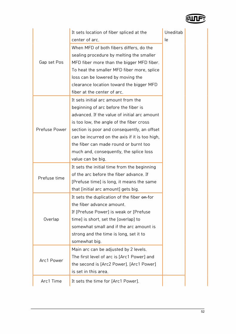
Gap set Pos
It sets location of fiber spliced at the center of arc.
Uneditable
When MFD of both fibers differs, do the sealing procedure by melting the smaller MFD fiber more than the bigger MFD fiber. To heat the smaller MFD fiber more, splice loss can be lowered by moving the clearance location toward the bigger MFD fiber at the center of arc.
Prefuse Power
It sets initial arc amount from the beginning of arc before the fiber is advanced. If the value of initial arc amount is too low, the angle of the fiber cross section is poor and consequently, an offset can be incurred on the axis if it is too high, the fiber can made round or burnt too much and, consequently, the splice loss value can be big.
Prefuse time
It sets the initial time from the beginning of the arc before the fiber advance. If [Prefuse time] is long, it means the same that [initial arc amount] gets big.
Overlap
It sets the duplication of the fiber on for the fiber advance amount. If [Prefuse Power] is weak or [Prefuse time] is short, set the [overlap] to somewhat small and if the arc amount is strong and the time is long, set it to somewhat big.
Arc1 Power
Main arc can be adjusted by 2 levels. The first level of arc is [Arc1 Power] and the second is [Arc2 Power]. [Arc1 Power] is set in this area.
Arc1 Time It sets the time for [Arc1 Power].

53
Arc2 Power [Arc2 Power] is the second level of arc. [Arc2 Power] is set in this area.
Arc2 Time
It sets the time for [Arc2 Power].
Uneditable
Editable
It sets the time for [Arc2 Power]. [Arc time 2] is generally set as “OFF.” It can set the arc time as a very long time period but when [Arc1 Time] and [Arc2 Time] exceed 30 seconds, the electrodes can be damaged.
Arc2 On - Time
While [Arc2 Power] is on arc, you can set the arc amount as “ON” and “OFF” in turn. The time period for [Arc2 Power] being “On” is set in this area. For re-arc, set the arc time as “ON” at all times.
Arc2 Off - Time
It sets the time period for the arc of [Arc2 Power] when it is turned off. When [Arc2 Power] is occasionally stopped, re-arc can also be stopped. When re-arc is continuously required, set as to “OFF.”
Rearc Time
It sets re-arc time.
Editable
Within [splice mode edition], it automatically sets to arc the re-arc amount with the same intensity as that of [Arc2 Power]. If [Arc2 Power] is set as ON/OFF, re-arc is automatically changed.
Taper Splice Off
When the fiber is made thin, the splice loss is sometimes increased. This pulling function is set to “OFF.” The following 3 parameters decide the pulling shape.
Unedietable

54
Taper Wait It designates the time period from the last of the advanced fiber amount to the beginning of pulling.
Taper Speed It sets the fiber pulling speed.
Taper Length It sets the fiber pulling time.
Editable
Offset
It is the sum of the initially measured splice loss value and the increased loss. When splicing a special fiber or other fibers, high loss may be incurred in spite of optimum arc conditions. To match the estimated splice loss and the actual splice loss, the minimum value of actual splice loss should be set.
6.1.5 Selection
Press and the selected splice mode is saved on memory and it is used upon splicing.
6.1.6 Close
Press and it goes back to the previous stage.

55
6.2 Heater
To display heater mode, press and then select “Heater” from the menu with
button. It displays a screen to select the heater mode as follows. The selecting screen is equipped with various heater modes to facilitate the user’s easy selection and use of the heater mode. In addition, heater mode can be expanded and saved for up to 100 modes. Heater mode no. 1~16 cannot be deleted or replaced either.
56
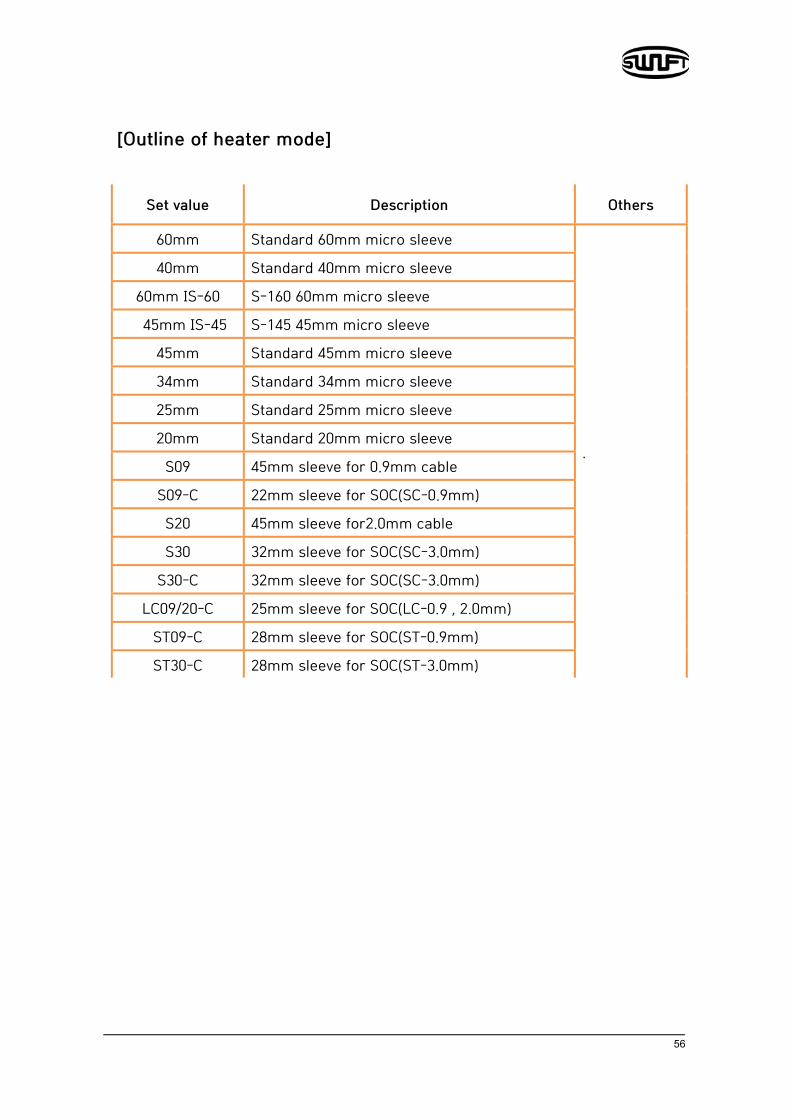
[Outline of heater mode]
Set value Description Others
60mm Standard 60mm micro sleeve
.
40mm Standard 40mm micro sleeve
60mm IS-60 S-160 60mm micro sleeve
45mm IS-45 S-145 45mm micro sleeve
45mm Standard 45mm micro sleeve
34mm Standard 34mm micro sleeve
25mm Standard 25mm micro sleeve
20mm Standard 20mm micro sleeve
S09 45mm sleeve for 0.9mm cable
S09-C 22mm sleeve for SOC(SC-0.9mm)
S20 45mm sleeve for2.0mm cable
S30 32mm sleeve for SOC(SC-3.0mm)
S30-C 32mm sleeve for SOC(SC-3.0mm)
LC09/20-C 25mm sleeve for SOC(LC-0.9 , 2.0mm)
ST09-C 28mm sleeve for SOC(ST-0.9mm)
ST30-C 28mm sleeve for SOC(ST-3.0mm)
57
6.2.1 Deletion
First, select a heater mode by pressing . And then press and the selected mode is deleted. General modes no. 1~16 cannot be deleted.
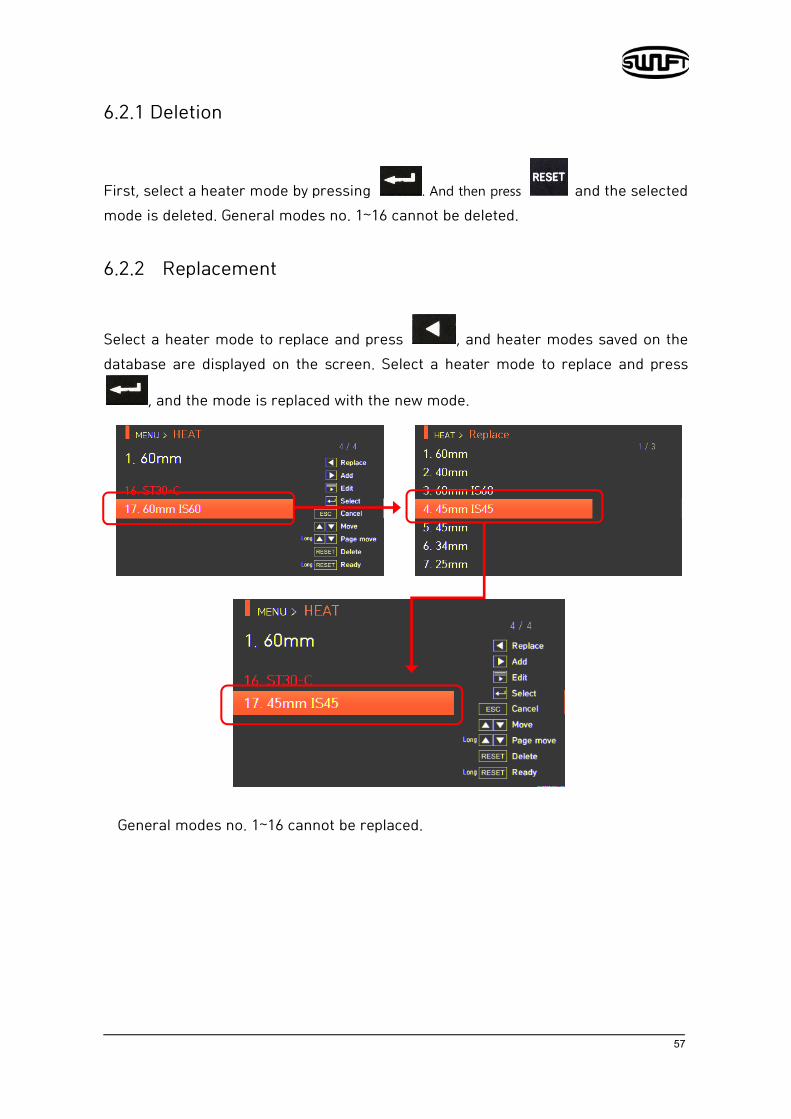
6.2.2 Replacement
Select a heater mode to replace and press , and heater modes saved on the database are displayed on the screen. Select a heater mode to replace and press
, and the mode is replaced with the new mode.
General modes no. 1~16 cannot be replaced.

58
6.2.3 Addition
Press and heater modes saved on the database are displayed on the screen.
Select a heater mode to add and press , and the mode is added. The newly added mode is located on the last number.
Addition cannot be made on general modes no. 1~16.
59
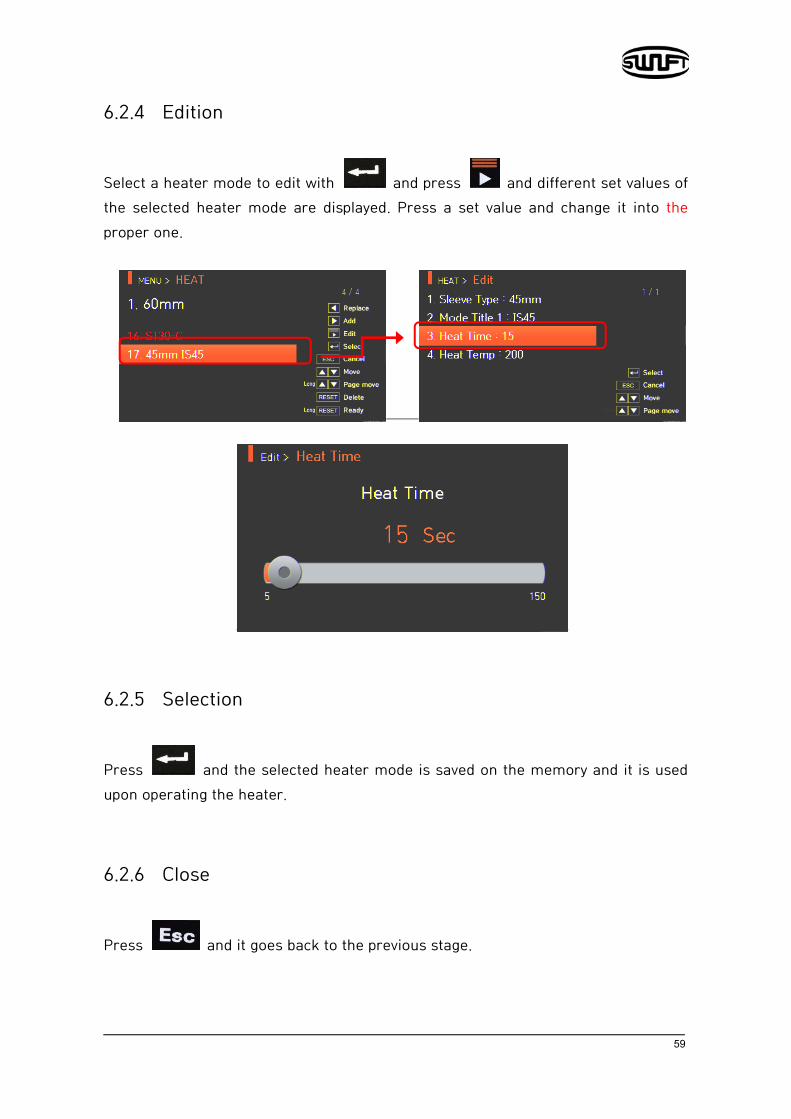
6.2.4 Edition
Select a heater mode to edit with and press and different set values of the selected heater mode are displayed. Press a set value and change it into the proper one.
6.2.5 Selection
Press and the selected heater mode is saved on the memory and it is used upon operating the heater.
6.2.6 Close
Press and it goes back to the previous stage.

60
6.3 Stripping
To display the stripping mode, press and then select “stripping” menu with
button. It displays a screen to select the stripping mode as follows. The selecting screen is equipped with various stripping modes to facilitate the user’s easy selection and use of the stripping mode. In addition, stripping mode can be expanded and saved for up to 100 modes. Stripping mode no. 1~7 cannot be deleted or replaced either.
[Outline of stripping mode]
Parameters Description
Modes
Matching the sorts of fiber All stripping lists are displayed. The user may copy or chose program mode that is required or
desired.
Stripping time As the stripping time can be selected between 0sec ~ 15.0sec,
select the proper one for fiber sheath.
Stripping temperature Set stripping temperature.

61
6.3.1 Deletion
First, select a stripping mode by pressing . And then press and the selected mode is deleted. General modes no. 1~7 cannot be deleted.
6.3.2 Replacement
Select a stripping mode to replace and press , and then the stripping modes saved on the database are displayed on the screen. Select a stripping mode to replace
and press , and the mode is replaced with the new mode.
General modes no. 1~7 cannot be replaced.

62
6.3.3 Addition
Press and stripping modes saved on the database are displayed on the screen.
Select a stripping mode to add and press , and the mode is added. The newly added mode is located by the last number.
Any additions cannot be made on general modes no. 1~7.

63
6.3.4 Edition
Select a splice mode to edit with and press and then different set values of the selected stripping mode are displayed. Press a set value and change it into the proper one.
6.3.5 Selection
Press and the selected stripping mode is saved on the memory and it is used when operating the heater.
6.3.6 Close
Press and it goes back to the previous stage.

64
6.4 Splice result
To display splice mode, press and then the “Splice result” menu with button. It displays a screen to select splice result menu. The splice result menu is equipped with various functions for a user to identify and delete splice result and images.
6.4.1 Splice result display It can save up to 10,000 splice data and images and the user can identify them. Each
page shows 7 splice data and images and it goes to the next page by pressing
.
65
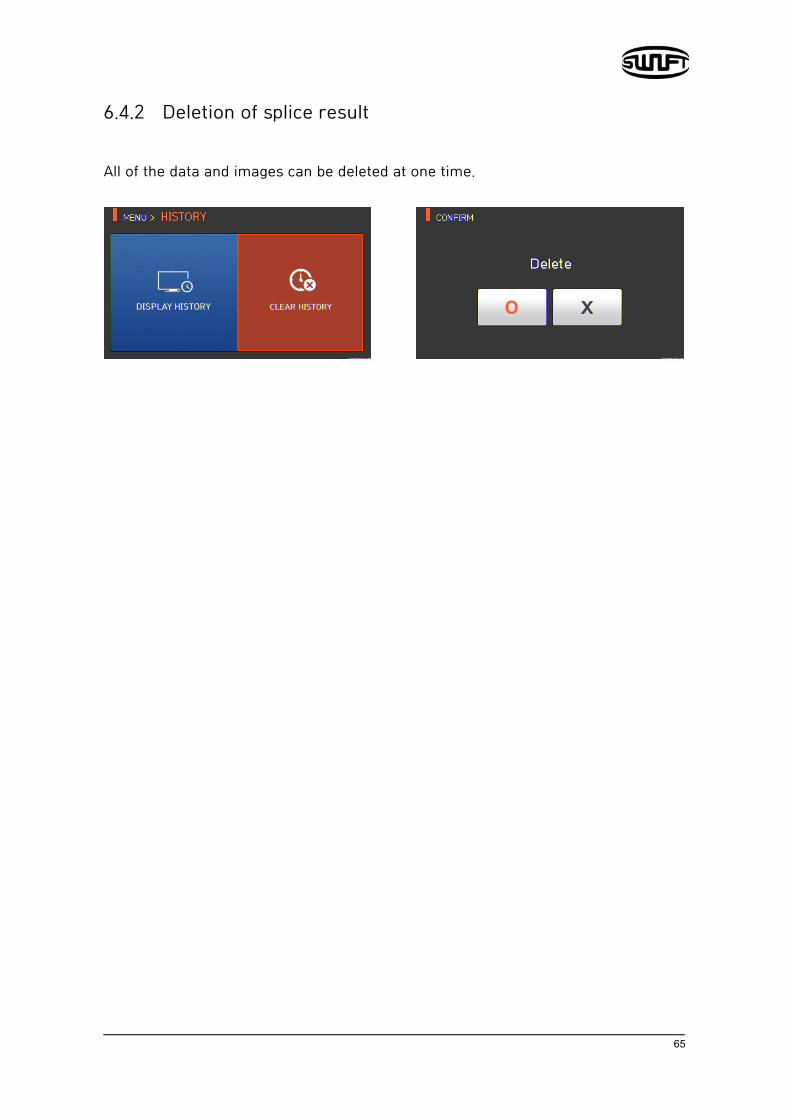
6.4.2 Deletion of splice result All of the data and images can be deleted at one time.

66
6.5 Option
To display option menu, press and then select “option” menu with button. It displays a screen to select an option menu as follows. The option menu is equipped with various functions to provide a user with better environment for operation
6.5.1 Splice operation Splice operation consists of 4 sub-checkboxes. As the user marks a checkbox, and each function is activated.

67
Set value Description
Auto Splice automatically starts when closing the wind cover.
Pause 1 It temporarily stops after first alignment completes.
Press and it goes to the next step.
Pause 2 It temporarily stops after clad alignment completes.
Press and it goes to the next step.
Auto Heat Heater operates automatically after splice completes.
6.5.2 Menu lock This menu includes a function to restrict access to the splice mode and heater mode setting and another function to disable the deletion of the splice result. After activating this lock function, even the access to menu for menu lock can also be restricted. Password entry is required to release this restriction so a user should memorize the password. If a user forgets the password, he should send the equipment to Ilsintech to reset the password.
Test item Description
1 Splice Lock It restricts modification on splice mode.
2 Heat Lock It restricts modification on heater mode.
3 Clear Memory Lock It restricts deletion of splice result.
4 Password Query It shows a screen to enter your own password. The initial password is “1234”.

68
6.5.3 Password
Password can be changed as follows.
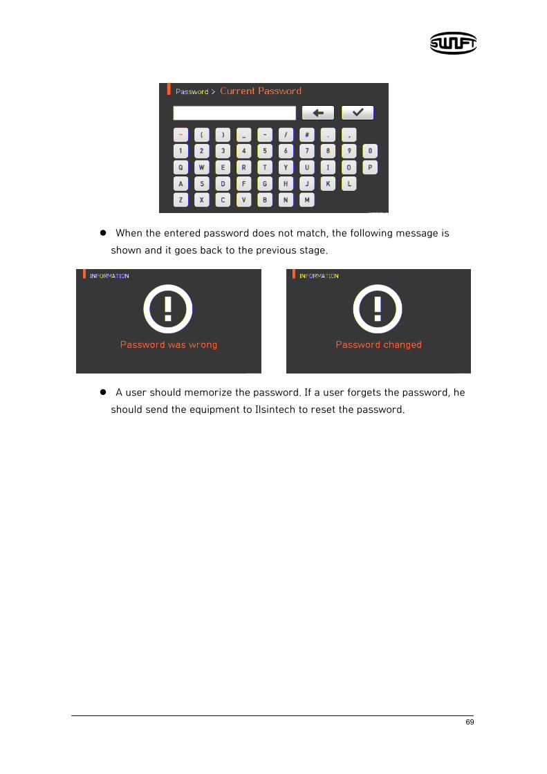
i. Enter the current password. The initial password is “1234”.
ii. Enter a new password.
iii. Enter the new password again.
69
When the entered password does not match, the following message is shown and it goes back to the previous stage.
A user should memorize the password. If a user forgets the password, he should send the equipment to Ilsintech to reset the password.
70
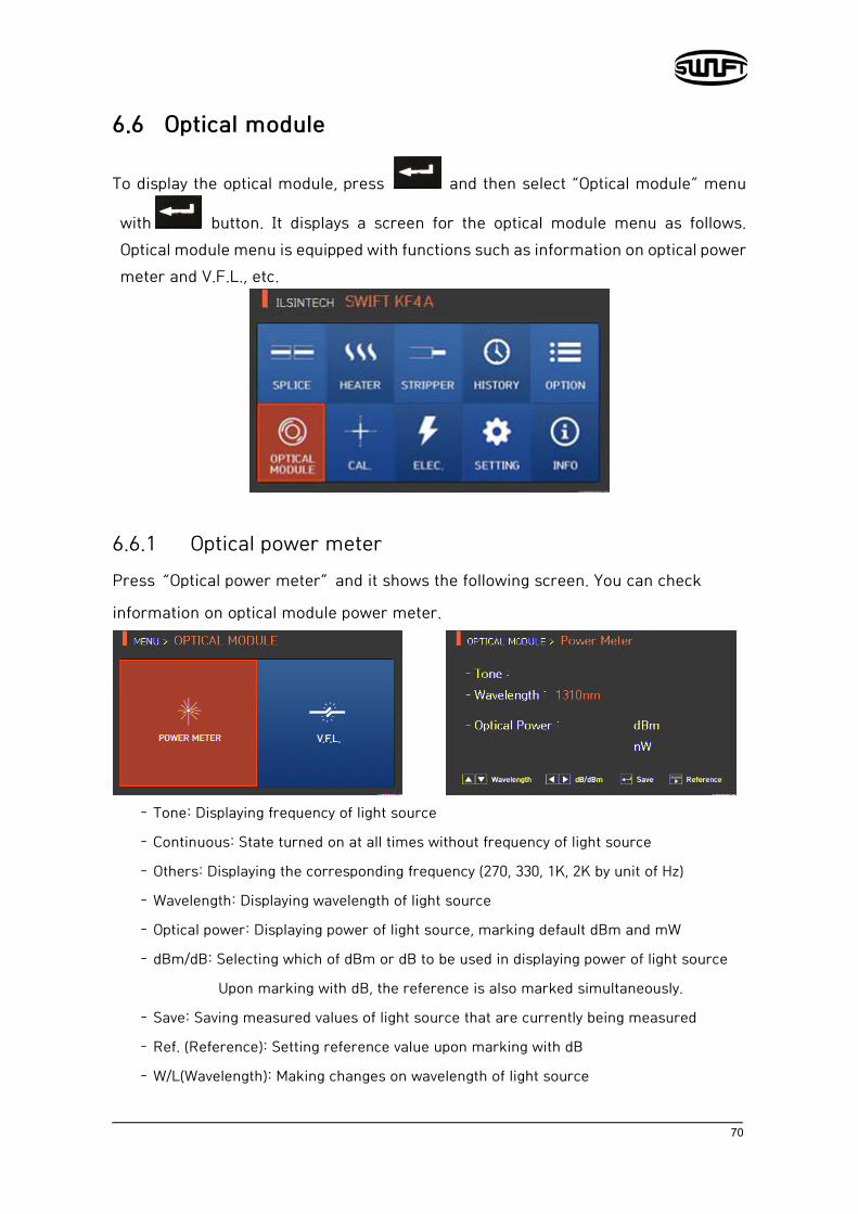
6.6 Optical module
To display the optical module, press and then select “Optical module” menu
with button. It displays a screen for the optical module menu as follows. Optical module menu is equipped with functions such as information on optical power meter and V.F.L., etc.
6.6.1 Optical power meter Press “Optical power meter” and it shows the following screen. You can check
information on optical module power meter.
– Tone: Displaying frequency of light source
– Continuous: State turned on at all times without frequency of light source
– Others: Displaying the corresponding frequency (270, 330, 1K, 2K by unit of Hz)
– Wavelength: Displaying wavelength of light source
– Optical power: Displaying power of light source, marking default dBm and mW
– dBm/dB: Selecting which of dBm or dB to be used in displaying power of light source
Upon marking with dB, the reference is also marked simultaneously.
– Save: Saving measured values of light source that are currently being measured
– Ref. (Reference): Setting reference value upon marking with dB
– W/L(Wavelength): Making changes on wavelength of light source

71
– Menus moved with left and right keys and operation performed with the enter key
6.6.2 V.F.L.
i. Connect SOC to V.F.L and check whether the fiber is disconnected with the
disconnection check being turned on.
ii. Upon flickering, V.F.L is activated with 2~3 Hz.
iii. When you finish using V.F.L, turn it back to the off state.
Blindness can be incurred when you see the light output from V.F.L with naked eye
so please be careful.
72
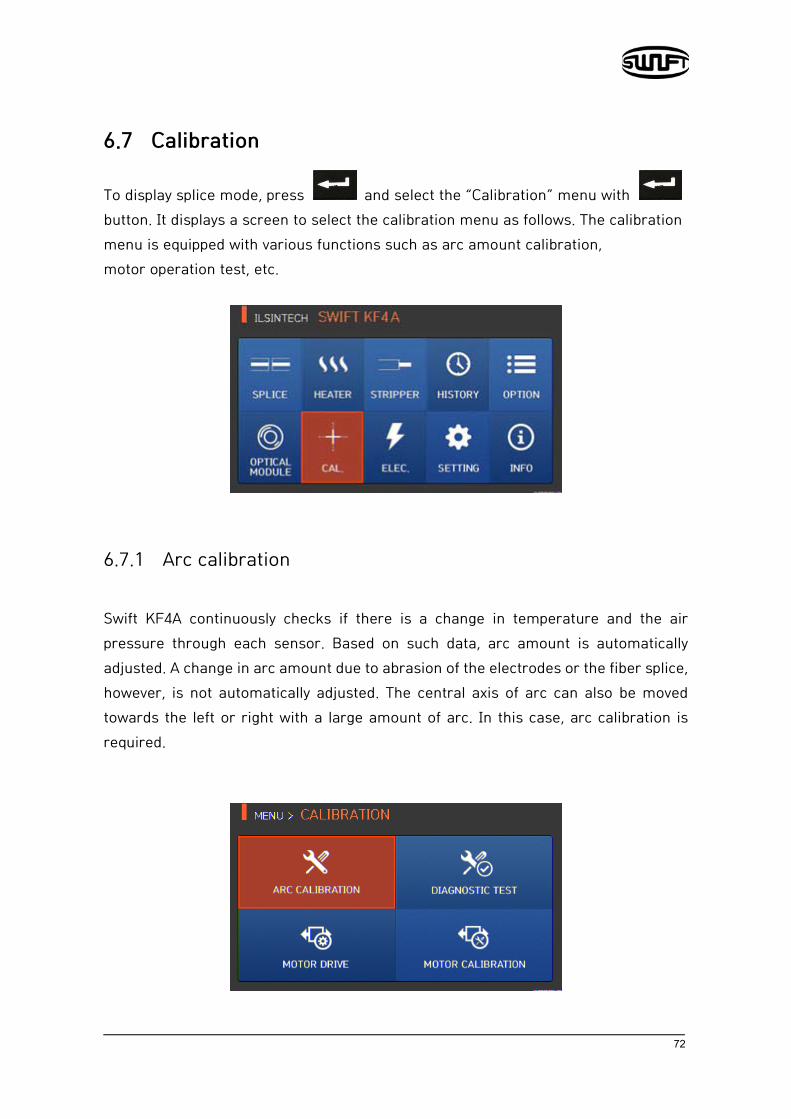
6.7 Calibration
To display splice mode, press and select the “Calibration” menu with button. It displays a screen to select the calibration menu as follows. The calibration menu is equipped with various functions such as arc amount calibration, motor operation test, etc.
6.7.1 Arc calibration Swift KF4A continuously checks if there is a change in temperature and the air pressure through each sensor. Based on such data, arc amount is automatically adjusted. A change in arc amount due to abrasion of the electrodes or the fiber splice, however, is not automatically adjusted. The central axis of arc can also be moved towards the left or right with a large amount of arc. In this case, arc calibration is required.

73
When executing arc calibration, arc voltage is automatically changed into a proper value. As this value is calculated by a certain computing program, a user cannot arbitrarily change it.
Upon arc amount calibration, SM fiber should be used.
i. Put a prepared SM fiber on splicer.
ii. Press as follows.
iii. When arc calibration completes, the following screen is displayed.
iv. If it is necessary to stop the arc even before the arc calibration is completed,
it immediately stops when pressing .

74
6.7.2 Diagnostic test The diagnostic test is a function to facilitate dust examination, LED examination and motor test and calibration at a time.
Test item Description
1 Dust testing Conducts dust test without fiber.
2 LED testing Conducts LED test without fiber.
3 Motor testing Conducts motor test
4 Heater testing Conducts heater test

75
6.7.3 Motor drive Motor drive checks whether the motor operates normally in manual mode.
i. Remove the fiber from the splicer.
ii. Select “Motor drive” with button.
iii. Change the motor selection by pressing . The name of the selected motor is indicated at the top of the screen.
iv. Operate the motor in a direction wanted by pressing .
Motor
X/Y Makes fiber go bottom Makes fiber go up
ZR Makes right fiber go backward Makes right fiber go forward
ZL Makes left fiber go forward Makes left fiber go backward
S Moves step by step upon every press of the button.
M Continuously moves upon pressing the button.

76
6.7.4 Motor Calibration
Motor setting is set on splicer as default but depending on motor setting location, splice speed may slow down. If the speed slows down during the splice operation or any abnormality is incurred while in the entering position, the motor setting can be automatically calibrated through this function.
i. Put the fiber on the splicer.
ii. Select “Motor calibration” with button. i. If an error message is displayed after testing, immediately contact
Ilsintech.
iii. End the calibration by pressing .

77
6.8 Electrodes
To display electrodes mode, press and then select “ELEC” menu with button. It displays a screen to select electrodes menu as follows. For using the splicer, it should be regularly cleaned due to electrodes abrasion and precipitation of silica oxide. This menu is related to checking electrodes use count and electrodes exchange and includes 4 submenus.
78
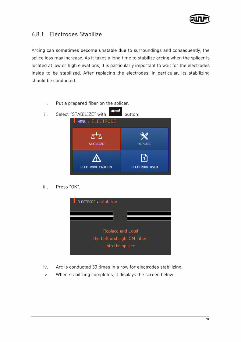
6.8.1 Electrodes Stabilize Arcing can sometimes become unstable due to surroundings and consequently, the splice loss may increase. As it takes a long time to stabilize arcing when the splicer is located at low or high elevations, it is particularly important to wait for the electrodes inside to be stabilized. After replacing the electrodes, in particular, its stabilizing should be conducted.
i. Put a prepared fiber on the splicer.
ii. Select “STABILIZE” with button.
iii. Press “OK”.
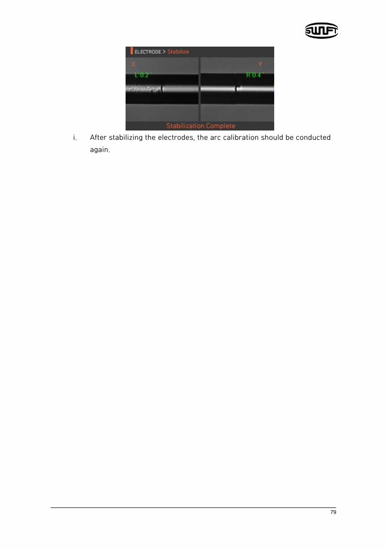
iv. Arc is conducted 30 times in a row for electrodes stabilizing. v. When stabilizing completes, it displays the screen below.
79
i. After stabilizing the electrodes, the arc calibration should be conducted
again.

80
6.8.2 Electrodes Replace
It is recommended to replace an electrodes when the number of arc reaches 3,000 times. When it exceeds the preset number of times for replacement, a message informing electrodes replacement is displayed.
6.8.3 Electrodes Caution The number of times to inform electrodes replacement is set on this menu. It is recommended to replace an electrodes when its use reaches 3,000 times.
6.8.4 Number of Electrodes Use It indicates the number of electrodes used as counted up to the present time.

81
6.9 Setting
To display setting mode, press and then select “Setting” menu with button. It displays a screen to select setting menu as follows.
6.9.1 Language A screen to select a language is dispalyed.
82
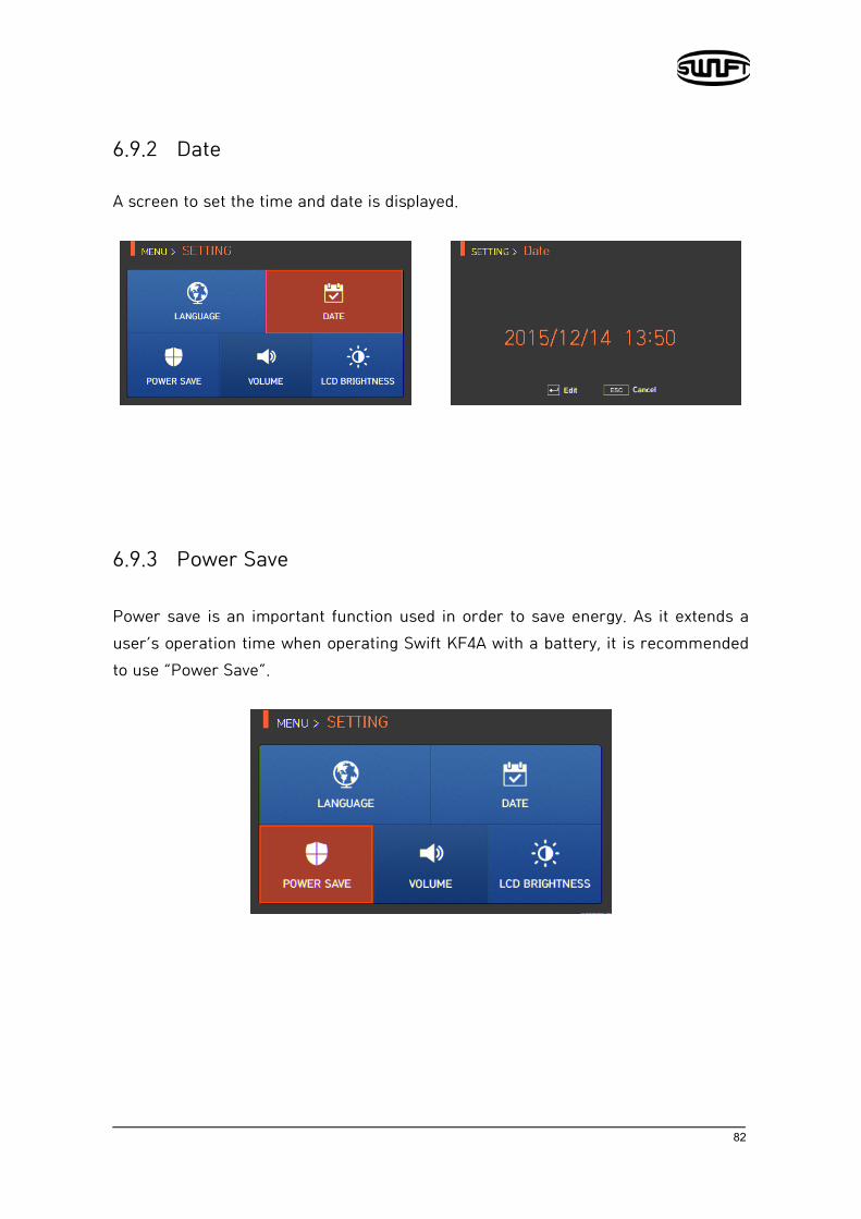
6.9.2 Date
A screen to set the time and date is displayed.
6.9.3 Power Save Power save is an important function used in order to save energy. As it extends a user’s operation time when operating Swift KF4A with a battery, it is recommended to use “Power Save”.

83
6.9.4 Monitor When Swift KF4A is not used for a preset time period, the LCD screen automatically turns off. With the push of any button, the screen turns on again
6.9.5 Splicer
When Swift KF4A is not used for the preset time period, power is automatically turned off.
The power is turned on again only when pressing .
84
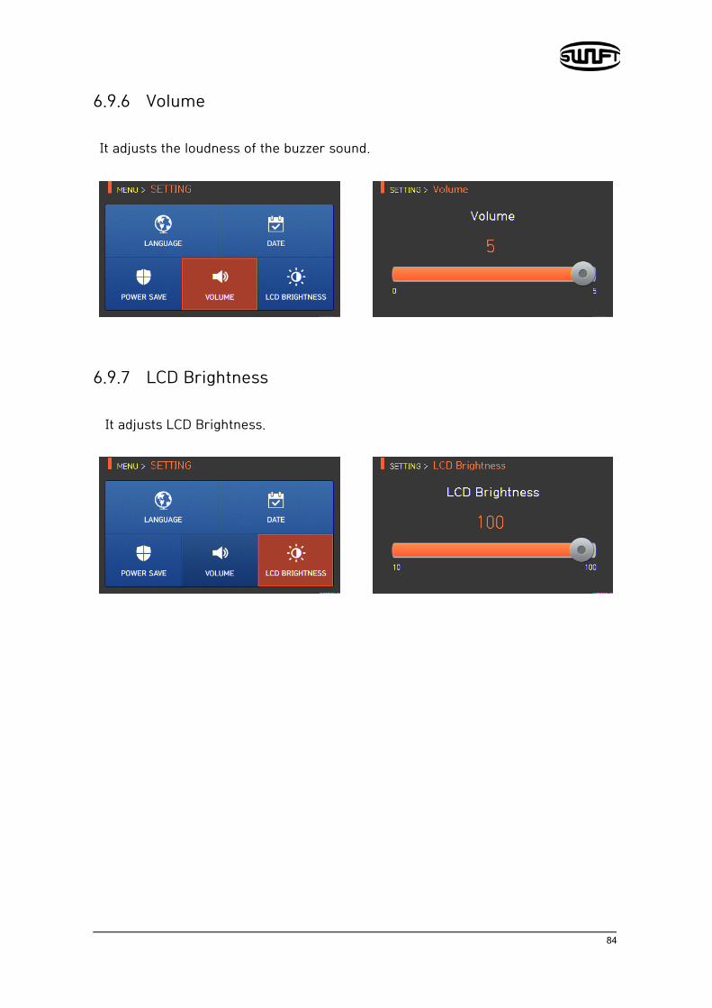
6.9.6 Volume It adjusts the loudness of the buzzer sound.
6.9.7 LCD Brightness
It adjusts LCD Brightness.

85
6.10 Information
To display information mode, press and select “INFO” menu with button. It displays a screen to select information menu as follows. This menu provides information for maintenance.
6.10.1 Maintenance Press “Maintenance” and it displays the screen below.
Item Description
Produce Date Describes the date of the equipment’s manufacture. (year, month, day)
Electric number Indicates the number of arc after the electrodes replacement.
Total electric num Indicates the total amount of arc after the product’s release.
Last Maintenance Indicates the date of recent maintenance.
Next Maintenance Indicates the next maintenance date.
Serial Number Indicates serial number given to the equipment.

86
6.10.2 Sensor Press the “Sensor” and it displays the screen below. Splicer has sensors to check the temperature, air pressure
6.10.3 Version Press “Version” and it displays the screen below. The version can be upgraded easily by connecting to a PC and using the DataSync program (PC Program).

87
6.10.4 Help
Press “Help” and it displays the screen below.
Item Description
The Name of Part Names of each component on Swift KF4A
Clean and Inspection Cleaning and inspection method
Warnings Important warnings
A/S Contact List Contact information for warranty

88
Error message 7.1 Too Dirty Fiber It is an error message generated when the fiber prepared for splicing contains foreign substances exceeding a normal level. Solution: Repeat splice after cleaning the fiber.
7.2 Replace Fiber. It is an error message generated when the fiber is not located in the right location or there is a foreign substance on the object lens or reflector.
Solution: Press and put the fiber on the right location again. Clean the object lens and reflector.

89
7.3 Too Long Fiber. It is an error message generated when the fiber is located too close to the electrodes; object lens or reflector is dirty or the LED is not sufficiently bright enough.
Solution: Press and put the fiber on a right location yet again. Clean the object lens and reflector. Conduct LED test. If an error occurs upon performing the LED test, contact Ilsintech.
7.4 Fiber Over Angle It is an error message generated when the cleaved angle of the fiber is measured as bigger than the limit. Solution: Check the state of the fiber cleaver. Check the cleaved angle limit.
90
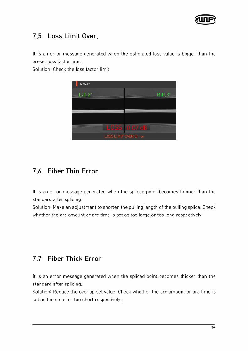
7.5 Loss Limit Over. It is an error message generated when the estimated loss value is bigger than the preset loss factor limit. Solution: Check the loss factor limit.
7.6 Fiber Thin Error It is an error message generated when the spliced point becomes thinner than the standard after splicing. Solution: Make an adjustment to shorten the pulling length of the pulling splice. Check whether the arc amount or arc time is set as too large or too long respectively.
7.7 Fiber Thick Error It is an error message generated when the spliced point becomes thicker than the standard after splicing. Solution: Reduce the overlap set value. Check whether the arc amount or arc time is set as too small or too short respectively.
91
7.8 Bubble error It is an error message generated when there are bubbles or spots being generated on spliced point after splicing. Solution: Examine the fiber cleaver. Clean the V-Groove. Examine the electrodes.
7.9 Cleaved Surface Error
It is an error message generated when the cut surface of fiber is of poor quality. Solution: Check the condition of the fiber cleaver. Cut the fiber yet again.
92
Splicing problem solving
8.1 When loss is high
Any dust or foreign substance on the fiber surface may incur poor splice. Clean the fiber surface sufficiently. Do not clean the fiber after cleaving to prevent dust from being
gathered on the fiber cross section. Do not push in the fiber when putting it on V-Groove.
The fiber should be placed from the top to bottom.
Any foreign substance on V-Groove hinders the correct alignment. Keep the V-Groove clean at all times.
Electrodes bad condition
When an electrodes contains an abrasion or its tip is bent and dirty, replace the electrodes.
Arc amount and arc time are inappropriate. Check the setting of arc amount and arc time to reset them with
proper values. Without any great change, the initially set values are the most
appropriate ones.
Inappropriate splice mode
Check whether appropriate splice mode is selected for the fiber.

93
8.2 Abnormal splicing operation
Alignment operation is repeated.
Open the wind cover again and then close.
If discontinues, open the wind cover, press and then turn off the power. Then contact Ilsintech.
The error message “Too Long Fiber” is continuously generated. Turn off the power and contact Ilsintech.

94
Problem occurrence and
question
9.1 Power
Power is not turned on by pressing .
Check whether the screen is turned off with the switch being pressed for about 1 second.
Cannot continue splicing after several times of splices even with the fully charged battery.
Power is quickly consumed when “Save mode” is not in use. Refer to the [Save Mode] and supply the power appropriately at all times. When the battery is not used for excessively long period time, recharge it.
If the battery’s life ends for long-term use, replace it with a new one. As the battery operates using chemical reaction, its wattage drops with low temperature and it rapidly drops particularly with temperatures below zero. As the splice current consumption goes up with high temperature, battery’s power consumption accelerates.
LED is not turned on upon charging.
Disconnect the charter’s AC power cord and connect the DC cord to the charging jack. Connect the AC power cord after 10~15 seconds. Then the battery’s LED is turned on red and charging starts.
Remaining battery is not indicated.
95
Charge the battery.
Remaining battery is not well displayed.
Remaining battery display is for reference.
9.2 Splice
Error message is displayed on the screen.
Refer to the [Error message list].
Splice loss is high or irregular.
Clean V-Groove, V-Block, reflector and object lens by referring to
[Maintenance of splice quality]. Replace electrodes by referring to [Electrodes replace]. Refer to the “High estimated loss” from [Error message list].
If fiber warps or is bent, place the fiber bent direction to face the bottom. Splice loss varies depending on cleaving angle, arc condition and cleanliness level of fiber. Splice loss is still high or irregular even after implementing the above recovery measures, contact to Ilsintech. Annual maintenance is required to keep splice optimal quality.
Monitor is suddenly turned off.
Refer to [Monitor sleep mode menu].
Power is suddenly turned off.
Refer to [Splicer sleep mode menu].
Either arc amount or arc time cannot be changed.
On SM, NZ, MM or AUTO mode, either arc amount or arc time cannot be changed. Implement [Arc Calibration], and the arc amount on

96
these modes is properly maintained. When used on another mode, arc amount and arc time are automatically set to prevent their alteration.

97
I’d like to set pause.
Refer to [Option menu].
I’d like to indicate cleaved angle, fiber angle and clad deviation.
Refer to [Option menu].
Estimated splice loss and measured splice loss does not match.
The estimated splice loss is a calculated value so it should be used only as a reference.
9.3 Sleeve heater Fiber protecting sleeve is not contracted completely.
Increase the heating time. Refer to [Heater mode edition].
Heater is overheated.
Stop the heater by pressing , turn the power off and then contact Ilsintech.
If the protecting sleeve melts and it sticks to the heater cover, remove it by pushing it with a cotton swab.
I’d like to initialize heater mode’s heating condition.
Refer to [Heat mode edition].
I’d like to cancel heater in the middle of operation.
Heater operation cannot be canceled by pressing . Cancel it by
pressing once again.
9.4 Others

98
I’d like to restrict splice mode and heater mode setting.
Refer to [Menu lock].
Splice mode’s arc amount does not change even after [Arc calibration]. The internal standard arc amount is calibrated. Therefore, the arc
amount of each splice mode does not change.
I forgot the password.
Contact Ilsintech.

99
Warranty and Repair
Responsibility limit Ilsintech guarantees its product regarding the product’s material and flaws from the manufacturing. With normal use and service, we guarantee the entire hardware of the product for the term of guarantee. When a problem is incurred during the term of guarantee, the product is to be repaired or exchanged free of charge by Ilsintech’s own judgment. When a flaws or damages are incurred for any of the reasons listed below, the repair expense may be charged to the customer even under warranty.
i. Natural disaster ii. Abnormal voltage supply iii. User’s careless handling iv. Product handling with disregard on working procedure or directions written
on instructions for use v. Consumables (electrodes, etc)
10.1 Information necessary for repair
Before sending the product, contact Ilsintech first.
i. Give us following information by attaching a paper to the product. (Name, Department, Company, Address, Contact information, FAX, E-MAIL)
ii. Product serial number iii. Product condition and problem incurred, Error Information iv. Product handling with disregard to working procedure or directions written
on instructions for use

100
10.2 Transportation
As Swift KF4A is a high-precision device, please send it along in the carry case to protect it from humidity, vibration and shock. When requesting the product repair, send its components as well by putting them in the carry case.
10.3 Repair
Newly made splice mode or splice result may be or may be not deleted depending on the repair work performed.
101
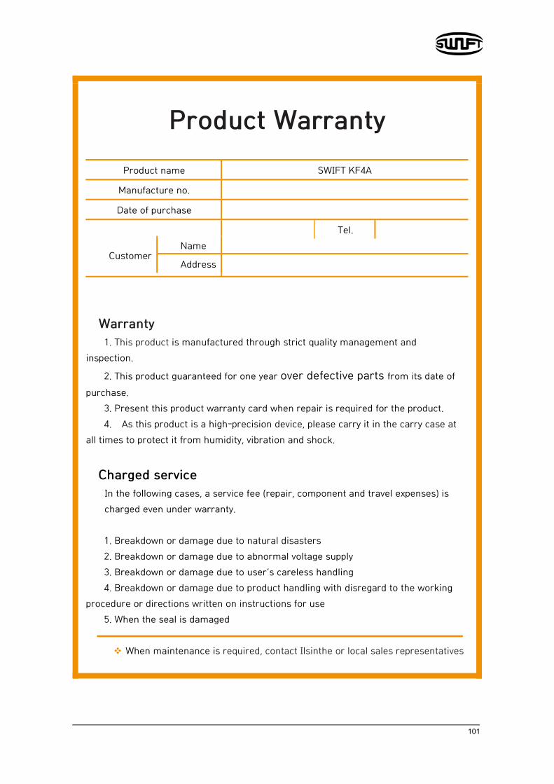
Product Warranty
Product name SWIFT KF4A
Manufacture no.
Date of purchase
Tel.
Customer Name
Address
Warranty 1. This product is manufactured through strict quality management and
inspection.
2. This product guaranteed for one year over defective parts from its date of purchase.
3. Present this product warranty card when repair is required for the product. 4. As this product is a high-precision device, please carry it in the carry case at
all times to protect it from humidity, vibration and shock.
Charged service In the following cases, a service fee (repair, component and travel expenses) is charged even under warranty. 1. Breakdown or damage due to natural disasters 2. Breakdown or damage due to abnormal voltage supply 3. Breakdown or damage due to user’s careless handling 4. Breakdown or damage due to product handling with disregard to the working
procedure or directions written on instructions for use 5. When the seal is damaged
When maintenance is required, contact Ilsinthe or local sales representatives