RC-1614 - Design and Construction Guidelines for ...
368
1 Design and Construction Guidelines for Strengthening Bridges using Fiber Reinforced Polymers (FRP) MDOT Reference Number: OR10-039 FINAL REPORT September 30, 2014 Prepared For: Michigan Department of Transportation Research Administration 425 West Ottawa Street Lansing MI 48933 Prepared By: Wayne State University 5050 Anthony Wayne Drive Detroit, MI 48202 Authors: Christopher D. Eamon Hwai-Chung Wu Abdel A. Makkawy Sasan Siavashi
Transcript of RC-1614 - Design and Construction Guidelines for ...

1
Design and Construction Guidelines for
Strengthening Bridges using Fiber Reinforced Polymers (FRP)
MDOT Reference Number: OR10-039
FINAL REPORT
September 30, 2014 Prepared For: Michigan Department of Transportation Research Administration 425 West Ottawa Street Lansing MI 48933 Prepared By: Wayne State University 5050 Anthony Wayne Drive Detroit, MI 48202 Authors: Christopher D. Eamon Hwai-Chung Wu Abdel A. Makkawy Sasan Siavashi

2
1. Report No. RC-1614
2. Government Accession No. N/A
3. MDOT Project Manager Steven Kahl
4. Title and Subtitle Design and Construction Guidelines for Strengthening Bridges using Fiber Reinforced Polymers (FRP)
5. Report Date 9/30/2014 6. Performing Organization Code N/A
7. Author(s) Christopher D. Eamon, Hwai-Chung Wu, Abdel A. Makkawy, and Sasan Siavashi
8. Performing Org. Report No. N/A
9. Performing Organization Name and Address Wayne State University Dept. of Civil and Environmental Engineering 5050 Anthony Wayne Drive Detroit, Michigan 48202
10. Work Unit No. (TRAIS) N/A 11. Contract No. 2010-0298 11(a). Authorization No. Z7
12. Sponsoring Agency Name and Address Michigan Department of Transportation Research Administration 425 West Ottawa Street Lansing MI 48933
13. Type of Report & Period Covered Final Report 10/1/2012 to 9/30/2014 14. Sponsoring Agency Code N/A
15. Supplementary Notes 16. Abstract This research concerns the development of guidelines for the design and use of externally-bonded FRP strengthening systems on bridges in Michigan. Six representative international FRP-related guidelines were analyzed and compared for applicability and effectiveness to MDOT needs. An experimental program involving natural and accelerated laboratory weathering was conducted to determine acceleration factors appropriate for the climate of Michigan. Bond pull-off and other specimen tests were used to establish rates of strength degradation, and an environmental reduction factor was estimated from these results. From the review of the existing guidelines as well as the test results, recommendations for design as well as installation, quality control, inspection, maintenance and repair were proposed that are based on modifications to as well as a synthesis of existing provisions. 17. Key Words Bridges, Strengthening, FRP, CFRP, Composites, Laminates, Design, Construction
18. Distribution Statement No restrictions. This document is available to the public through the Michigan Department of Transportation.
19. Security Classification - report Unclassified
20. Security Classification - page Unclassified
21. No. of Pages 368
22. Price N/A

3
DISCLAIMER
This publication is disseminated in the interest of information exchange. The Michigan
Department of Transportation (hereinafter referred to as MDOT) expressly disclaims any
liability, of any kind, or for any reason, that might otherwise arise out of any use of this
publication or the information or data provided in the publication. MDOT further disclaims any
responsibility for typographical errors or accuracy of the information provided or contained
within this information. MDOT makes no warranties or representations whatsoever regarding
the quality, content, completeness, suitability, adequacy, sequence, accuracy or timeliness of the
information and data provided, or that the contents represent standards, specifications, or
regulations.

4
TABLE OF CONTENTS
LIST OF TABLES .......................................................................................................................... 8
LIST OF FIGURES ...................................................................................................................... 11
EXECUTIVE SUMMARY .......................................................................................................... 18
CHAPTER 1: INTRODUCTION ................................................................................................. 20
1.1 Statement of the Problem ......................................................................................... 20
1.2 Background ............................................................................................................... 20
1.2.1 Introduction .................................................................................................. 20
1.2.2 Current design approach concepts ............................................................... 22
1.2.3 Delamination ................................................................................................ 23
1.2.4 Durability ..................................................................................................... 23
1.3 Objectives of the Study ............................................................................................ 23
1.4 Summary of Research Tasks .................................................................................... 24
CHAPTER 2: LITERATURE REVIEW ...................................................................................... 25
2.1 Introduction .............................................................................................................. 25
2.2 FRP Constituents ...................................................................................................... 25
2.2.1 Fibers............................................................................................................ 25
2.2.2 Matrix ........................................................................................................... 26
2.2.3 FRP strengthening systems .......................................................................... 27
2.2.4 Composite interfacial adhesion and debonding ........................................... 27
2.2.5 Current design standards and guides............................................................ 30
2.2.6 Designing with FRP reinforcement ............................................................. 31
2.2.7 Flexural strengthening ................................................................................. 32
2.2.8 Shear strengthening ...................................................................................... 32
2.2.9 Numerical modeling..................................................................................... 33
2.2.10 Delamination .............................................................................................. 34
2.2.11 Durability ................................................................................................... 35
2.2.12 Accelerated weathering testing .................................................................. 35
2.2.13 Installation of externally bonded FRP systems .......................................... 36
CHAPTER 3: DESIGN PROVISIONS ........................................................................................ 38

5
3.1 Introduction .............................................................................................................. 38
3.2 Flexural FRP Strengthening of RC/PC Bridge Members ......................................... 38
3.2.1 Introduction .................................................................................................. 38
3.2.2 Strengthening Limits .................................................................................... 39
3.2.3 Environmental Reduction Factors ................................................................ 42
3.2.4 FRP Strain Limits ........................................................................................ 45
3.2.5 Strength Reduction Factors .......................................................................... 49
3.2.6 Serviceability and Service Load Limits ....................................................... 56
3.2.7 Creep Rupture and Fatigue Stress Limits .................................................... 59
3.2.8 End Peeling .................................................................................................. 65
3.2.9 Development Length .................................................................................... 71
3.2.10 Flexural Design Approach and Assumptions ............................................ 74
3.3 Shear FRP Strengthening of RC/PC Bridge Members ............................................. 88
3.3.1 Introduction .................................................................................................. 88
3.3.2 Wrapping schemes ....................................................................................... 88
3.3.3 Strength reduction factors ............................................................................ 90
3.3.4 Reinforcement limits and spacing limits ...................................................... 91
3.3.5 FRP design strain limits ............................................................................... 97
3.3.6 Shear design approach and assumptions .................................................... 100
3.4 FRP Confinement Strengthening of RC/PC Bridge Members ............................... 121
3.4.1 Introduction ................................................................................................ 121
3.4.2 Design considerations ................................................................................ 121
3.4.3 Analysis and Design Procedures ................................................................ 126
3.4.4 Summary .................................................................................................... 134
3.5 Witness Panels ........................................................................................................ 150
CHAPTER 4: PROVISIONS FOR INSTALLATION, QC, AND MAINTENANCE .............. 151
4.1 Introduction ............................................................................................................ 151
4.2. Installation of CFRP Strengthening Systems ........................................................ 151
4.2.1 Introduction ................................................................................................ 151
4.2.2 Shipping, storage, and handling ................................................................. 151
4.2.3 Contractor qualifications ............................................................................ 157

6
4.2.4 Installation Procedures ............................................................................... 159
4.3 Inspection, Evaluation, and Acceptance ................................................................. 175
4.3.1 Introduction ................................................................................................ 175
4.3.2 Inspection ................................................................................................... 175
4.3.3 Evaluation and acceptance ......................................................................... 181
4.4 Maintenance and Repair ......................................................................................... 193
4.4.1 Introduction ................................................................................................ 193
CHAPTER 5: LABORATORY TESTING ................................................................................ 198
5.1 Durability Testing Overview .................................................................................. 198
5.1.1 Introduction ................................................................................................ 198
5.1.2 Materials procurement ............................................................................... 198
5.1.3 Testing program ......................................................................................... 199
5.2 Materials Properties ................................................................................................ 199
5.2.1 Concrete sample preparation and properties .............................................. 199
5.2.2 FRP material properties ............................................................................. 201
5.2.3 Sample preparation for FRP strengthening ................................................ 207
5.2.4 Application of FRP to concrete samples .................................................... 208
5.3 Test Plan and Procedures ........................................................................................ 210
5.3.1 Summary of test specimens ....................................................................... 210
5.3.2 Test plan ..................................................................................................... 215
5.3.3 Pull-off testing ........................................................................................... 218
5.3.4 Flexural, shear and confinement testing .................................................... 220
5.4 Test Results ............................................................................................................ 220
5.4.1 Pull-off testing ........................................................................................... 220
5.4.2 Testing of structural samples ..................................................................... 227
CHAPTER 6: FIELD TESTS ..................................................................................................... 236
6.1 Introduction ............................................................................................................ 236
6.2 Dolly Installation and Testing ................................................................................ 237
6.3 Test Results ............................................................................................................ 239
CHAPTER 7: COMPARISON DESIGN ................................................................................... 246
7.1. Design Assumptions .............................................................................................. 246
7
7.1.1 Column ....................................................................................................... 246
7.1.2 FRP reinforcement ..................................................................................... 246
7.1.3 Additional assumptions .............................................................................. 246
7.2 Calculations ............................................................................................................ 247
7.2.1 ACI design, rectangular column ................................................................ 247
7.2.2 ACI design, modified column .................................................................... 248
7.2.3 AASHTO design, rectangular column ....................................................... 249
7.2.4 AASHTO design, modified column .......................................................... 251
7.3 Summary ................................................................................................................. 253
CHAPTER 8: RECOMMENDATIONS..................................................................................... 254
8.1 Analysis and Design Recommendations ................................................................ 254
8.1.1 Criteria for recommendations .................................................................... 254
8.1.2 General recommendation and discussion................................................... 254
8.1.3 Recommended modifications to AASHTO provisions ............................. 256
8.2 Installation, QC, and Maintenance Recommendations .......................................... 260
8.2.1 Shipping, storage, and handling ................................................................. 261
8.2.2 Manufacturer and contractor qualification ................................................. 263
8.2.3 Installation.................................................................................................. 264
8.2.4 Inspection ................................................................................................... 269
8.2.5 Evaluation and acceptance ......................................................................... 273
REFERENCES ........................................................................................................................... 279
APPENDIX A: NOMENCLATURE ......................................................................................... 293
APPENDIX B: DESIGN EXAMPLES ...................................................................................... 326
APPENDIX C: INSPECTION CHECKLIST ............................................................................. 361
APPENDIX D: MODIFICATIONS TO EXISTING MDOT SPECIFICATIONS ................... 367
8
LIST OF TABLES
Table 2.1 - Typical reinforcing fiber material properties ............................................................. 26
Table 2.2 - Mechanical properties of commonly used FRP epoxies ............................................ 27
Table 2.3 - Properties of FRP systems from Sika and Fyfe ......................................................... 28
Table 2.4 - Bidirectional laminate selection offered by Sika ....................................................... 29
Table 3.2.1 - Environmental reduction factors ............................................................................. 43
Table 3.2.2 - Environmental conversion factor ....................................................................... 44
Table 3.2.3 - Material resistance factors ....................................................................................... 44
Table 3.2.4 - AASHTO environmental reduction factors for GFRP bars .................................... 45
Table 3.2.5 - ISIS and ACI reduction factor comparison ............................................................. 51
Table 3.2.6 - Example partial safety factors for strength at ultimate limit state (TR55 Table 5.2)
....................................................................................................................................................... 53
Table 3.2.7 - Recommended partial safety factors for manufactured composites (TR55 Table 5.3)
....................................................................................................................................................... 53
Table 3.2.8 - partial safety factor for modulus of elasticity at ultimate (TR55 Table 5.4) .......... 53
Table 3.2.9 - CNR partial safety factor ................................................................................. 55
Table 3.2.10 - CNR partial factor for materials and products, ................................................ 55
Table 3.2.11 - Strength reduction factors with and without environmental factor ....................... 56
Table 3.2.12 - Reduction factor values for concrete, steel and CFRP .......................................... 56
Table 3.2.13 - Summary of service limit state .............................................................................. 58
Table 3.2.14 - ACI sustained plus cyclic service load stress limit in FRP reinforcement ............ 59
Table 3.2.15 - ISIS maximum stress level against creep rupture .................................................. 59
Table 3.2.16 - Conversion factor for long term effects for several FRP systems for service limit
states .............................................................................................................................................. 61
Table 3.2.17 - Maximum Stress range as a percentage of the design ultimate strength materials
....................................................................................................................................................... 61
Table 3.2.18 - Maximum stress range under service loads to avoid stress rupture for different .. 62
Table 3.2.19 - FRP limits due to creep rupture and cyclic loading .............................................. 64
Table 3.2.20 - Peeling summary ................................................................................................... 69
Table 3.3.1- Maximum shear resistance allowed.......................................................................... 93
Table 3.3.2 - Maximum spacing of FRP shear reinforcement ...................................................... 95
Table 3.3.3 - Specified maximum FRP strain for different codes .............................................. 100
Table 3.4.1 - Strength reduction factor ....................................................................................... 122

9
Table 3.4.2 - Maximum FRP strain due to confinement............................................................. 124
Table 3.4.3 - FRP stress limits .................................................................................................... 125
Table 4.2.1 - Maximum depth of depressions on the concrete surface....................................... 165
Table 4.2.2 - Maximum allowable concrete crack width beyond which injection is required ... 174
Table 4.2.3 - Minimum allowable lap splice length ................................................................... 175
Table 4.2.4 - Minimum radius for roundness of concrete corners .............................................. 175
Table 4.3.1 - Minimum resolution for defects to be identified with non-destructive tests ......... 191
Table 4.3.2 - Minimum acceptable tension strength of adhesive ............................................... 192
Table 4.3.3 - Maximum allowable area of delamination ............................................................ 192
Table 5.2.1 - Concrete compressive test results .......................................................................... 201
Table 5.2.2 - Sika fiber properties .............................................................................................. 201
Table 5.2.3 - Physical properties of Sika laminate ..................................................................... 202
Table 5.2.4 - Mechanical properties of Sika laminate ................................................................ 202
Table 5.2.5 - SikaDur 300 and SikaDur Hex 330 properties ...................................................... 203
Table 5.2.6 - SikaDur 30 properties ............................................................................................ 203
Table 5.2.7 - Fyfe fiber material properties ................................................................................ 204
Table 5.2.8 - Physical properties of Fyfe laminate ..................................................................... 204
Table 5.2.9 - Mechanical properties of Fyfe laminate ................................................................ 205
Table 5.2.10 - Fyfe epoxy properties .......................................................................................... 205
Table 5.2.11 - Material properties of MBrace CF130 ................................................................ 206
Table 5.2.12 - Material properties of MBrace primer ................................................................. 206
Table 5.2.13 - Material properties of MBrace saturant ............................................................... 207
Table 5.2.14 - Material properties of MBrace putty ................................................................... 207
Table 5.3.1 - FRP strengthened samples for flexural structural testing ...................................... 210
Table 5.3.2 - FRP strengthened samples for shear structural testing .......................................... 211
Table 5.3.3 - FRP strengthened samples for confinement structural testing .............................. 211
Table 5.3.4 - FRP strengthened samples for pull-off adhesion testing ....................................... 212
Table 5.3.5 - FRP strengthened samples for pull-off adhesion testing ....................................... 212
Table 5.3.6 - Accelerated specimens subjected to pull-off tests ................................................ 217
Table 5.3.7 - Outdoor specimens subjected to pull-off tests....................................................... 217
Table 5.4.1 - Results of completed pull-off testing of outdoor samples ..................................... 221
Table 5.4.2 - Results of completed pull-off testing of accelerated samples ............................... 223
Table 5.4.3 - Results of accelerated and control flexural beam sample testing .......................... 227

10
Table 6.1 - Column 6, Face 1 test results and failure modes ...................................................... 240
Table 6.2 - Column 6, Face 2 test results and failure modes ...................................................... 240
Table 6.3 - Column 6, Face 3 test results and failure modes ...................................................... 240
Table 6.4 - Column 6, Face 4 test results and failure modes ...................................................... 240
Table 6.5 - Column 2, Face 1 test results and failure modes ...................................................... 241
Table 6.6 - Column 2, Face 2 test results and failure modes ...................................................... 241
Table 6.7 - Column 2, Face 3 test results and failure modes ...................................................... 241
Table 6.8 - Column 2, Face 4 test results and failure modes ...................................................... 241
Table 8.2.1 - Maximum depth of depressions on the concrete surface....................................... 265

11
LIST OF FIGURES
Figure 3.2.1 - ACI strengthening limits at elevated temperatures ................................................ 41
Figure 3.2.2 - FRP strengthening limits for different codes (with fixed dead load of 50 psf) ..... 43
Figure 3.2.3 - Comparison of environmental reduction factors .................................................... 44
Figure 3.2.4 - Effect of concrete compressive strength f‘c on FRP strain limits (number of FRP
layers = 3, area = 0.33 in2) ........................................................................................................... 49
Figure 3.2.5 - Effect of amount of FRP strengthening on FRP strain limits, f‘c =5.5 ksi ............. 49
Figure 3.2.6 - Strength reduction factor for GFRP (adopted from AASHTO GFRP manual) .... 52
Figure 3.2.7 - Equivalent reduction factors corresponding to material partial safety factors, ,
for ultimate strength limit state ..................................................................................................... 54
Figure 3.2.8 - Equivalent reduction factors corresponding to manufacturing process partial safety
factors, , for select processes ................................................................................................. 54
Figure 3.2.9 - Equivalent reduction factors corresponding to of select materials and
manufacturing processes ............................................................................................................... 54
Figure 3.2.10 - TR55 Maximum stress range as a proportion of the design ultimate strength .... 62
Figure 3.2.11 - TR55 Maximum stress range under service loads to avoid stress rupture ........... 62
Figure 3.2.12 - Summary of FRP fatigue/creep rupture coefficients ............................................ 64
Figure 3.2.13 - Characteristic bond failure force vs. anchorage length. ....................................... 67
Figure 3.2.14 - Peeling stress vs. FRP strengthening area ............................................................ 70
Figure 3.2.15 - Peeling Stress vs f‘c ............................................................................................. 70
Figure 3.2.16 - Development length as a function of f‘c, ksi ........................................................ 73
Figure 3.2.17 - Development length as a function of FRP area, in2 ............................................. 73
Figure 3.2.18 - Effect of amount of FRP flexural strengthening on unfactored moment
(ρ=0.0033) .................................................................................................................................... 79
Figure 3.2.19 - Effect of amount of FRP flexural strengthening on unfactored moment
(ρ=0.0064) .................................................................................................................................... 79
Figure 3.2.20 - Effect of amount of FRP flexural strengthening on unfactored moment
(ρ=0.0171) .................................................................................................................................... 80
Figure 3.2.21 - Effect of amount of FRP flexural strengthening on factored moment (ρ=0.0033)
....................................................................................................................................................... 80
Figure 3.2.22 - Effect of amount of FRP flexural strengthening on FRP strain (ρ=0.0033) ....... 81
Figure 3.2.23 - Effect of amount of FRP flexural strengthening on factored moment (ρ=0.0064)
....................................................................................................................................................... 81
Figure 3.2.24 - Effect of amount of FRP flexural strengthening on FRP strain (ρ=0.0064) ....... 82

12
Figure 3.2.25 - Effect of amount of FRP flexural strengthening on factored moment (ρ=0.0171)
....................................................................................................................................................... 82
Figure 3.2.26 - Effect of amount of FRP flexural strengthening on FRP strain (ρ=0.0171) ....... 83
Figure 3.2.27 - Effect of f‘c on unfactored moment (ρ=0.0033) .................................................. 83
Figure 3.2.28 - Effect of f‘c on unfactored moment (ρ=0.0064) .................................................. 84
Figure 3.2.39 - Effect of f‘c on unfactored moment (ρ=0.0171) .................................................. 84
Figure 3.2.30 - Effect of f‘c on factored moment (ρ=0.0033) ...................................................... 85
Figure 3.2.31 - Effect of f‘c on factored moment (ρ=0.0064) ...................................................... 85
Figure 3.2.32 - Effect of f‘c on factored moment (ρ=0.0171) ...................................................... 86
Figure 3.2.33 - Effect of f‘c on FRP strain (ρ=0.0033) ................................................................ 86
Figure 3.2.34 - Effect of f‘c on FRP strain (ρ=0.0064) ................................................................ 87
Figure 3.2.35 - Effect of f‘c on FRP strain (ρ=0.0171) ................................................................ 87
Figure 3.3.1 - a) Fibers at 90o direction, b) Fibers at inclined direction. ...................................... 89
Figure 3.3.2 - Recommended application of wrapping schemes in ISIS. ..................................... 89
Figure 3.3.3 - Typical anchoring systems for FRP shear reinforcement described in ISIS. ........ 90
Figure 3.3.4 - FRP strength reduction factor ................................................................................ 91
Figure 3.3.5 - Effect of on allowed ................................................................................. 94
Figure 3.3.6 - Effect of strip width on maximum strip spacing, d = 12 ........................................ 95
Figure 3.3.7 - Effect of strip width on maximum strip spacing, d = 24 ........................................ 96
Figure 3.3.8 - Effect of strip width on maximum strip spacing, d = 36 ........................................ 96
Figure 3.3.9 - Effect of strip width on maximum strip spacing, d = 48 ........................................ 97
Figure 3.3.10 - Effect of strip width on maximum strip spacing, d = 60 ...................................... 97
Figure 3.3.11 - CNR shear strengthening notation. .................................................................... 106
Figure 3.3.12 - Unfactored fiber shear resistance vs FRP spacing, width = 6 in, U-wrap ......... 111
Figure 3.3.13 - Unfactored fiber shear resistance vs FRP spacing, width = 8 in, U-wrap ......... 111
Figure 3.3.14 - Unfactored fiber shear resistance vs FRP spacing, width = 10 in, U-wrap ....... 112
Figure 3.3.15 - Unfactored fiber shear resistance vs FRP spacing, width = 12 in, U-wrap ....... 112
Figure 3.3.16 - Factored fiber shear resistance vs FRP spacing, width = 6 in, U-wrap ............. 113
Figure 3.3.17 - Factored fiber shear resistance vs FRP spacing, width = 8 in, U-wrap ............. 113
Figure 3.3.18 - Factored fiber shear resistance vs FRP spacing, width = 10 in, U-wrap ........... 114
Figure 3.3.19 - Factored fiber shear resistance vs FRP spacing, width = 12 in, U-wrap ........... 114
Figure 3.3.20 - Unfactored fiber shear resistance, U-wrap, continuous ..................................... 115
Figure 3.3.21 - Factored fiber shear resistance, U-wrap , continuous ........................................ 115
13
Figure 3.3.22 - Effect of strip spacing on U-wrap and 2 sided wraping, wf = 6 in .................... 116
Figure 3.3.23 - Effect of strip spacing on U-wrap and 2 sided wraping, wf = 8 in .................... 116
Figure 3.3.24 - Effect of FRP strip width on total shear resistance when gap = d/4 .................. 117
Figure 3.3.25 - Effect of FRP strip width on FRP shear resistance when gap = d/4 .................. 117
Figure 3.3.26 - Effect of the ratio of dfrp/d on unfactored FRP shear resistance ....................... 118
Figure 3.3.27 - Effect of beam height on total shear resistance, steel stirrup spacing = 9 in ..... 118
Figure 3.3.28 - Effect of beam height on total shear resistance, steel stirrup spacing = 12 in ... 119
Figure 3.3.29 - Effect of beam height on total shear resistance, steel stirrup spacing = 15 in ... 119
Figure 3.3.30 - Effect of beam height on FRP shear resistance, kips steel stirrup spacing = 9 in
..................................................................................................................................................... 120
Figure 3.3.31 - Effect of beam height on steel shear resistance steel stirrup spacing = 9 in ...... 120
Figure 3.3.32 - Effect of beam height on concrete shear resistance, steel stirrup spacing = 9 in
..................................................................................................................................................... 121
Figure 3.4.1 - ACI stress-strain model for FRP-confined concrete (Lam and Teng, 2003a) .... 128
Figure 3.4.2 - Equivalent circular cross section (Lam and Teng 2003) ..................................... 129
Figure 3.4.3 - Elevation view of circular member confined with FRP strips. ............................ 133
Figure 3.4.4 - Confinement of rectangular sections. ................................................................... 133
Figure 3.4.5 - Effect of changing fc' on factored axial load resistance, square column, ρ=0.02
..................................................................................................................................................... 135
Figure 3.4.6 - Effect of changing f‘c on unfactored axial load resistance, square column, ρ=0.02
..................................................................................................................................................... 135
Figure 3.4.7 - Effect of changing f‘c on factored axial load resistance, square column, ρ=0.03
..................................................................................................................................................... 136
Figure 3.4.8 - Effect of changing f‘c on unfaactored axial load resistance, square column, ρ=0.03
..................................................................................................................................................... 136
Figure 3.4.9 - Effect of changing f‘c on factored axial load resistance, square column, ρ=0.04 137
Figure 3.4.10 - Effect of changing f‘c on unfactored axial load resistance, square column, ρ=0.04
..................................................................................................................................................... 137
Figure 3.4.11 - Effect of changing f‘c on factored axial load resistance, circular column, ρ=0.02
..................................................................................................................................................... 138
Figure 3.4.12 - Effect of changing f‘c on unfactored axial load resistance, circular column,
ρ=0.02 ......................................................................................................................................... 138
Figure 3.4.13 - Effect of changing f‘c on factored axial load resistance, circular column, ρ=0.03
..................................................................................................................................................... 139
Figure 3.4.14 - Effect of changing f‘c on unfactored axial load resistance, circular column,
ρ=0.03 ......................................................................................................................................... 139

14
Figure 3.4.15 - Effect of changing f‘c on factored axial load resistance, circular column, ρ=0.04
..................................................................................................................................................... 140
Figure 3.4.16 - Effect of changing fc' on unfactored axial load resistance, circular column,
ρ=0.04 ......................................................................................................................................... 140
Figure 3.4.17 - Effect of changing number of plies on factored axial load resistance, square
column, ρ=0.02 ........................................................................................................................... 141
Figure 3.4.18 - Effect of changing number of plies on unfactored axial load resistance, square
column, ρ=0.02 ........................................................................................................................... 141
Figure 3.4.19 - Effect of changing number of plies on factored axial load resistance, square
column, ρ=0.03 ........................................................................................................................... 142
Figure 3.4.20 - Effect of changing number of plies on unfactored axial load resistance, square
column, ρ=0.03 ........................................................................................................................... 142
Figure 3.4.21 - Effect of changing number of plies on factored axial load resistance, square
column, ρ=0.04 ........................................................................................................................... 143
Figure 3.4.22 - Effect of changing number of plies on unfactored axial load resistance, Square
column, ρ=0.04 ........................................................................................................................... 143
Figure 3.4.23 - Effect of changing number of plies on unfactored axial load resistance, circular
column, ρ=0.02 ........................................................................................................................... 144
Figure 3.4.24 - Effect of changing number of plies on factored axial load resistance, circular
column, ρ=0.02 ........................................................................................................................... 144
Figure 3.4.25 - Effect of changing number of plies on unfactored axial load resistance, circular
column, ρ=0.03 ........................................................................................................................... 145
Figure 3.4.26 - Effect of changing number of plies on factored axial load resistance, circular
column, ρ=0.03 ........................................................................................................................... 145
Figure 3.4.27 - Effect of changing number of plies on unfactored axial load resistance, circular
column, ρ=0.04 ........................................................................................................................... 146
Figure 3.4.28 - Effect of changing number of plies on factored axial load resistance, circular
column, ρ=0.04 ......................................................................................................................... 146
Figure 3.4.29 - Effect of changing number of plies on axial load capacity, circular column,
ρ=0.02 ......................................................................................................................................... 147
Figure 3.4.30 - Effect of changing number of plies on axial load capacity, square column, ρ=0.02
..................................................................................................................................................... 147
Figure 3.4.31 - Effect of changing f‘c on axial load capacity, circular column, ρ=0.02 ............. 148
Figure 3.4.32 - Effect of changing f‘c on axial load capacity, square column, ρ=0.02 ............... 148
Figure 3.4.33 - Effect of changing f‘c on axial load capacity, both circular and rectangular
columns, ρ=0.02 .......................................................................................................................... 149
Figure 3.4.34 - Effect of changing number of plies on axial load capacity, both circular and
rectangular columns, ρ=0.02 ....................................................................................................... 149

15
Figure 4.3.1 - Double lap shear test ............................................................................................ 189
Figure 5.2.1 - Typical plywood mold assembly ......................................................................... 199
Figure 5.2.2 - Fresh concrete surface finishing ........................................................................... 200
Figure 5.2.3 - Fresh concrete onsite testing ................................................................................ 200
Figure 5.2.4 - Surface grinding of concrete samples .................................................................. 208
Figure 5.2.5 - FRP installation using Fyfe FRP system .............................................................. 209
Figure 5.2.6 - Installed FRP system ............................................................................................ 209
Figure 5.3.1 - FRP strengthened samples for flexure using FRP wrap (fabric) ......................... 213
Figure 5.3.2 - FRP strengthened samples for flexure using FRP plates (sheets) ....................... 213
Figure 5.3.3 - FRP strengthened samples for 2-sided shear ....................................................... 214
Figure 5.3.4 - FRP strengthened samples using U-wrap ............................................................ 214
Figure 5.3.5 - Pull-off test samples using FRP wrap .................................................................. 214
Figure 5.3.6 - FRP strengthened confinement samples .............................................................. 215
Figure 5.3.7 - Outdoor samples exposed to natural weathering ................................................. 215
Figure 5.3.8 - Tenney environmental chamber ........................................................................... 216
Figure 5.3.9 - Accelerated testing cycle detail ............................................................................ 216
Figure 5.3.10 - Pull-off adhesion tester. ..................................................................................... 218
Figure 5.3.11 - Installation of dollies on a half-painted sample ................................................. 219
Figure 5.3.12 - Pull-off adhesion testing underway .................................................................... 219
Figure 5.3.13 - Loading set-up of a flexural sample ................................................................... 220
Figure 5.4.1a - Bond strength vs time for outdoor samples ........................................................ 224
Figure 5.4.1b - Bond strength vs number of cycles for accelerated sample 124 ........................ 224
Figure 5.4.2a - Bond strength vs time for outdoor samples ........................................................ 225
Figure 5.4.2b - Bond strength vs number of cycles for accelerated sample 124 ........................ 225
Figure 5.4.3 - Load vs displacement for accelerated (101, 102) and control (103, 104) beams 228
Figure 5.4.4a - Set up of accelerated sample 101 ....................................................................... 228
Figure 5.4.4b - Accelerated sample 101 initial cracking ............................................................ 228
Figure 5.4.4c - Accelerated sample 101 initial cracking ............................................................ 229
Figure 5.4.4d - Accelerated sample 101 peeling failure ............................................................. 229
Figure 5.4.4e - Accelerated sample 101 failure plane ................................................................ 229
Figure 5.4.5 - Failure mode observed in sample 101 is considered peeling or shear/tension failure
of concrete substrate ................................................................................................................... 230
Figure 5.4.6a - Accelerated sample 102 initial cracks- note shear crack to right ....................... 230

16
Figure 5.4.6b - Accelerated sample 102 failure (debonding/peeling) ....................................... 230
Figure 5.4.7a - Control sample 103 initial hairline cracks (flexure and shear cracks) .............. 231
Figure 5.4.7b - Control sample 103 shear crack ......................................................................... 231
Figure 5.4.7c - Control sample 103 failure (shear/peeling) ....................................................... 231
Figure 5.4.8a - Control sample 104 initial flexure cracking ....................................................... 232
Figure 5.4.8b - Control sample 104 progressive cracking .......................................................... 232
Figure 5.4.8c - Control sample 104 (shear/debonding) ............................................................. 232
Figure 5.4.9 - Compressive strengths of accelerated confined samples 119 and 120, and failed
control sample 121. .................................................................................................................... 233
Figure 5.4.10 - Confinement sample 121 FRP failure due to lack of end confinement at the
bottom prompting FRP to unravel upward ................................................................................. 234
Figure 5.4.11 - Confinement sample 119 failure due to FRP rupture ........................................ 234
Figure 5.4.12 - Confinement sample 120 failure due to FRP rupture ......................................... 234
Figure 5.4.13 - Bond strength for pull-off specimens and flexural tests (larger symbols) ........ 235
Figure 6.1 - Test columns ........................................................................................................... 236
Figure 6.2 - Test sample location ................................................................................................ 236
Figure 6.3 - Secured test dollies .................................................................................................. 237
Figure 6.4 - Test dollies installed on column 2, face 4 ............................................................... 237
Figure 6.5 - Removal of tape and elastic membrane to expose dollies for testing ..................... 238
Figure 6.6 - Coring around dollies for proper adhesive bond testing ......................................... 238
Figure 6.7 - Adhesive bond testing using PosiTest AT-A Automatic Adhesion Tester ............. 239
Figure 6.8 - Column 6 samples after testing ............................................................................... 242
Figure 6.9 - Column 2 samples after testing ............................................................................... 243
Figure 6.10 - Lack of adhesive bond due to lack of epoxy saturation of sample 623 ................ 244
Figure 6.11 - Presence of air bubbles in failure surface of select samples ................................. 245

17
ACKNOWLEDGEMENTS
The authors would like to thank several students at WSU for their help on this project. In
particular, we greatly appreciate the assistance of Adulkareem Kuaryouti, Vahid Kamjoo,
Alexander Lamb, Kapil Patki, Alaa Chehab, Alexander Andrew, Makdad Aezeh, Hayssam
Sabra. Also, we owe thanks to Wes Pringle of Sika, Dave McCarron of BASF, and Gaetano
Bologna of Fyfe for providing FRP materials and their valuable comments and directions for
specimen preparation.

18
EXECUTIVE SUMMARY
Over the last two decades, various codes, standards, and other guidelines have been proposed for
strengthening structures with externally-bonded fiber reinforced polymer (FRP) systems.
However, these documents offer different design and installation procedures and
recommendations, and were developed without reference to the particular needs of MDOT
bridge components. From a review and analysis of these existing guidelines as well as
experimental testing results, this project aims to provide suitable recommendations for design,
construction, maintenance, and inspection when strengthening Michigan bridge elements with
FRP composites. In particular, the primary goals of this study are to: develop a synthesis of
representative design and use guidelines for FRP strengthening with specific attention to
flexural, shear, and confinement; to develop recommendations for design and use specifically
relevant to MDOT needs; and to construct selections of the recommendations based on
laboratory and field testing.
As detailed in Chapter 2, the first task of this research was to conduct a comprehensive review of
the existing FRP strengthening literature. From this review, six representative international
guidelines were chosen for further analysis and evaluation:
American Concrete Institute (ACI) 440.2R-08, Guide for the Design and Construction of
Externally Bonded FRP Systems for Strengthening Concrete Structures;
Intelligent Sensing for Innovative Structures (ISIS) Design Manual 4, FRP Rehabilitation
of Reinforced Concrete Structures;
American Association of State and Highway Transportation Officials (AASHTO) Guide
Specifications for Design of Bonded FRP Systems for Repair and Strengthening of
Concrete Bridge Elements;
Japan Society of Civil Engineers (JSCE) Recommendations for Upgrading of Concrete
Structures with use of Continuous Fiber Sheets;
United Kingdom Concrete Society Technical Report 55 (TR55), Design Guidance for
Strengthening Concrete Structures Using Fibre Composite Materials, and;
Italian National Research Council Technical Document 200 (CNR-DT 200), Guide for
the Design and Construction of Externally Bonded FRP Systems.
In Chapter 3, the six guide provisions listed above were analyzed and compared with particular
attention to flexural, shear, and confinement strengthening. In general, it was found that many
analysis provisions were common to the six international guidelines, although various
differences emerged when reduction factors, strain limits, and other details of implementation
were included. For flexural strengthening, it was found that ACI, AASHTO, and ISIS were fairly
consistent with capacity prediction. For the cases studied, ACI was found to have greatest
capacity for lower FRP area and higher concrete strengths, while AASHTO and ISIS were found
to have greatest capacity for higher FRP areas, and TR55 was found to be relatively
conservative. In the case of shear, unfactored resistance values were similar, but when reduction
factors were applied, AASHTO and ACI generally provided the largest design capacities while
results for CNR, UK and ISIS were similar but lower. When the confinement of circular columns

19
was studied, it was found that CNR produced higher design values while AASHTO and TR55
were most conservative. For square columns, CNR similarly produced highest capacity while
ACI was most conservative. However, the codes converge to similar values for the unfactored
cases.
Chapter 4 presents the findings of a review of the installation and usage procedures presented in
the guidelines. It was found that coverage of installation procedures varies widely among codes.
While AASHTO and CNR contained little coverage of FRP installation, ACI and ISIS were the
most comprehensive. Similarly, ACI and ISIS provided related coverage of evaluation and
acceptance criteria, although ACI, TR55 and JSCE all present a relatively broad coverage of
maintenance and repair. In contrast, CNR's coverage of maintenance and repair is brief, while
ISIS and AASHTO do not provide detailed coverage of this subject.
As summarized in Chapter 5, a significant portion of the research effort of this project concerned
experimental testing. The purpose of the laboratory testing was to assess FRP system
degradation when exposed to the climate of Michigan and to develop recommendations for an
acceleration and environmental reduction factor specific for Michigan weather conditions. In this
effort, approximately 120 FRP-strengthened concrete specimens were prepared, and subjected to
accelerated weathering as well as natural outdoor weathering. A valuable source of long-term
Michigan exposure data was found from a 15 year old existing MDOT FRP installation that was
included in the test results. Pull-off testing, flexural, and confinement strength tests were
conducted to assess degradation and link accelerated test results to natural weathering results. In
this effort, specimens strengthened with Sika, Fyfe, and BASF systems were subjected up to 240
freeze-thaw cycles and compared to natural weathering results. By linking bond degradation
rates between the outdoor and laboratory-accelerated test results, short-term and long-term
acceleration factors were developed that allow estimation of bond losses due to natural Michigan
weathering based on accelerated test results.
From the results of the code analysis and testing portions of this project, Chapter 8 presents a
series of recommendations for design and use. In general, the AASHTO design provisions were
recommended with several modifications, including changes in strength reduction factors based
in part on ACI guidelines, allowable strain limits when prestressed concrete girder strengthening
is considered, and other factors. A second series of general recommendations for installation,
inspection and quality control, and maintenance and repair were suggested based on a review of
the available provisions. These recommendations were within the parameters set by existing
guidelines on these topics.

20
CHAPTER 1: INTRODUCTION
1.1 Statement of the Problem
Highway bridges deteriorate from various causes such as environmental conditions, traffic
loading, deferred maintenance, and collision damage. However, it is often expensive and
disruptive to replace weakened structural members. Although various traditional methods are
available to strengthen and repair bridge elements, a promising alternative is to utilize fiber
reinforced polymer (FRP) composite materials. Advantages include a high strength-to- weight
ratio, excellent corrosion resistance, and ease of installation. Common applications involve
externally bonded composite fabrics on beams, columns, and bridge decks, where a significant
improvement in compressive, shear, and flexural performance can be realized.
A significant number of general guidelines exist for the design and construction of FRP systems
for strengthening structural components, as detailed in this report. However, there is a need for
specific design guidelines for use of FRP composite materials for flexural, shear and
confinement strengthening of bridge elements in Michigan. Under service conditions, Michigan
bridges are subjected not only to traffic loads but also to a wide range of temperature and
moisture changes. In winter, deicing salts are widely used, and their effect must be considered as
part of the service environment. The effect of cold winters on FRP materials is of special
concern. Sub-zero temperatures may cause changes in mechanical properties of FRP material
and create additional damage, and the presence of deicing salts could accelerate such
deterioration (Wu et al. 2006a). In summers, high temperature, especially coupled with high
humidity, has a different but additional possible detrimental effect on FRP. The combination of
complex environmental and mechanical loading complicates the durability assessment of FRP
composites (Hollaway and Head 2001, Helbling et al. 2006), hence the long-term durability of
FRP-bonded bridges remains a major concern. With these as well as other critical factors in
mind, this project aims to provide a background for refined design, construction, maintenance,
and inspection guidelines for strengthening deteriorated Michigan bridge elements with FRP
composites.
1.2 Background
1.2.1 Introduction
The Michigan Department of Transportation (MDOT) conducts regular inspection of bridges and
overpasses across the state. Of 4406 bridges recently inspected, 271 were classified as
structurally deficient, while 634 bridges were classified as functionally obsolete. Moreover, 21%
of the bridges inspected were designated as requiring some form of retrofit, modification, or
upgrade to remove the deficiency and restore function (MDOT 2012). Bridge inspection and
reporting in Michigan is part of the larger, federally mandated National Bridge Inspection
Standards (NBIS) administered by the Department of Transportation (USDOT) Federal Highway
Administration (FHWA) (USDOT-FHWA 2004). The “2010 Status of the Nation’s Highways,
Bridges, and Transit: Conditions & Performance”, published by FHWA (2010), presents similar
deficiency levels for bridges nationally to that of the state of Michigan. Unsurprisingly,
according to FHWA data, older bridges are more likely to be structurally deficient and

21
functionally obsolete than newer ones. For example, the proportion of structurally deficient and
functionally obsolete bridges exceeds 40 percent in the 55 to 59 years old category, and 50
percent in the 80 to 84 years old category (Memmott 2007).
The unique Michigan environmental conditions may further accelerate the rate of deterioration of
highway bridges, as although bridges are expected to have a service life span of 50 to 100 years,
many are showing signs of distress much earlier. Extreme temperatures in the summer and
winter, including many cycles of freeze thaw, and the use of deicing salts, are factors that
contribute to the progressive damage of bridge structural members (Staton & Knauff 2007).
Other factors include heavy traffic loading, lack of adequate maintenance, and collision damage.
Depending on the bridge deficiency rating and nature, different corrective actions may be
required. Traditional methods of strengthening and rehabilitating steel bridges include
replacement of damaged structural members, repair of corroded beam ends, addition of
stiffeners, and application of protective coatings (Wipf et al. 2003). For concrete bridges,
traditional rehabilitation measures may include sealing of hairline cracks using epoxy injection,
spot-patching of damaged areas, waterproofing, jacketing structural members to restore/increase
their load carrying capacity, and cathodic protection against rebar corrosion. However, traditional
methods have inherent limitations. For example, spot patching methods can mend corrosion-
induced spalls, but typically do not retard chloride-induced corrosion since concrete containing
chlorides is difficult to remove completely. The corrosion rates are observed to be higher at the
perimeter of the patch and is independent of the type of patch material used (Tabatabai et al.
2005).
An alternative bridge rehabilitation method is to utilize FRP composite materials. Significant
benefits include a high strength to weight ratio, excellent corrosion resistance, and ease of
installation. Because of their light weight, FRP composites are cheaper to transport, require less
or no scaffolding to install, and minimally adds to the structure’s dead load. Due to the superior
strength properties of FRP composites, only thin layers are needed to rehab beams and columns,
minimally altering their dimensions. This is particularly important in maintaining bridge
vehicular clearance and other tolerances within acceptable limits.
Various documents have been developed in the last two decades describing FRP strengthening
systems. The most widely known guide in the US is ACI 440.2R, Guide for the Design and
Construction of Externally Bonded FRP Systems for Strengthening Concrete Structures (2008),
though many others exist, as discussed in this report.
Although there exist a significant number of design guides, other than the referenced MDOT
reports, these documents contain general FRP guidelines and consider generic applications,
without reference to the particular needs of MDOT bridge components or Michigan vehicle load
and weather conditions. Thus, a lack of knowledge exists for best practices for design,
evaluation, construction, maintenance, and inspection procedures for FRP strengthened bridges
in Michigan. Further, FRP materials and their technologies are relatively new to the Michigan
construction industry, and hence a knowledge gap exists for best practices and implementation.
In general, FRP composites are composed of two major constituents: the fibers (usually of glass,
aramid, or carbon), and a resin matrix. Typically, for the external application of FRP sheets, a

22
layer of dry fiber sheet (usually unidirectional tape) is placed on top of a coat of polymer resin
that hardens to bond the fiber sheet to the concrete structure. However, wet lay-up, precured,
and near surface mounted construction techniques have been used in practice. When needed,
multiple layers of fiber sheets can be sequentially added by repeating the same procedure. The
resulting properties and potential failure modes of an FRP composite structure are a function of
the properties of the fiber, the matrix, and their interfaces. The interface between the FRP sheet
and the concrete is particularly important, since composite action requires a solid bond. Final
failure is often caused by the debonding of the FRP sheet from the concrete substrate (Meier
1995, Buyukozturk and Hearing 1998). The degradation of a constituent in FRP over time
affects various composite properties, and may even change the order of governing failure modes
which may be matrix, fiber, or interface-dominated. This is a particularly important concern, as
a FRP bonded structure could failure abruptly due to a change in dominant failure mode.
1.2.2 Current design approach concepts
FRP materials have been used for compressive, flexural, and shear strengthening of reinforced
concrete structures since the late 1970s. FRP strengthening has since been established as a
potentially efficient and economical technique for the repair and rehabilitation of deteriorating
concrete structures, including bridges. To account for the complex behavior and various possible
failure mechanisms of FRP bonded structures, extensive experimental investigations were
carried out by numerous researchers (Seible et al. 1997, Mo et al. 2004, Nanni 2004, Ludovico et
al. 2005, Walker and Karbhari 2006). For FRP bonded flexural beams, several failure modes
were generally observed:
1. Crushing of the concrete in the compression zone before rupture of the FRP sheet or
yielding of the reinforcing steel (brittle failure).
2. Yielding of the tension steel before concrete crushing or rupture of FRP sheet (ductile
failure).
3. Yielding of the compression steel reinforcement of a doubly reinforced section
(relatively ductile failure).
4. Rupture of the FRP sheet before steel yield and the compressive strain in the concrete
is below its ultimate strain (the most brittle failure).
5. Anchorage failure (delamination) in the bond zone of the FRP sheet (often a ductile
failure).
6. Peeling or shear/tension failure of the concrete substrate near the FRP sheet’s cut off
zone (brittle failure).
These six failure modes were classified into two types by Thomsen (2004). Type one includes
modes exhibiting composite action up to failure, either due to concrete crushing, FRP rupture, or
lack of shear resistance. Type two consists of failures by loss of composite action due to
debonding of the FRP sheet, or by end peeling, where the concrete cover near the support regions
peels off. To avoid detachment failure at the FRP/concrete interface, ACI 440.2R (2008)
introduces a bond reduction factor (km) to limit the strain permitted in the FRP system. However,
due to the high cost of experimental research, values for the bond reduction factor were based on
a limited number of experimental investigations. Correspondingly, a critical factor potentially
not adequately accounted for is the potential deterioration of the bond strength over time.
According to ACI 440.2R, km is taken as a value no greater than 0.9, which reduces the usable
strength of the FRP below its ultimate rupture strain. Even so, FRP rupture or delamination
23
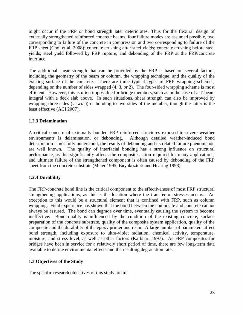
might occur if the FRP or bond strength later deteriorates. Thus for the flexural design of
externally strengthened reinforced concrete beams, four failure modes are assumed possible, two
corresponding to failure of the concrete in compression and two corresponding to failure of the
FRP sheet (Choi et al. 2008): concrete crushing after steel yields; concrete crushing before steel
yields; steel yield followed by FRP rupture; and debonding of the FRP at the FRP/concrete
interface.
The additional shear strength that can be provided by the FRP is based on several factors,
including the geometry of the beam or column, the wrapping technique, and the quality of the
existing surface of the concrete. There are three typical types of FRP wrapping schemes,
depending on the number of sides wrapped (4, 3, or 2). The four-sided wrapping scheme is most
efficient. However, this is often impossible for bridge members, such as in the case of a T-beam
integral with a deck slab above. In such situations, shear strength can also be improved by
wrapping three sides (U-wrap) or bonding to two sides of the member, though the latter is the
least effective (ACI 2007).
1.2.3 Delamination
A critical concern of externally bonded FRP reinforced structures exposed to severe weather
environments is delamination, or debonding. Although detailed weather-induced bond
deterioration is not fully understood, the results of debonding and its related failure phenomenon
are well known. The quality of interfacial bonding has a strong influence on structural
performance, as this significantly affects the composite action required for many applications,
and ultimate failure of the strengthened component is often caused by debonding of the FRP
sheet from the concrete substrate (Meier 1995, Buyukozturk and Hearing 1998).
1.2.4 Durability
The FRP-concrete bond line is the critical component to the effectiveness of most FRP structural
strengthening applications, as this is the location where the transfer of stresses occurs. An
exception to this would be a structural element that is confined with FRP, such as column
wrapping. Field experience has shown that the bond between the composite and concrete cannot
always be assured. The bond can degrade over time, eventually causing the system to become
ineffective. Bond quality is influenced by the condition of the existing concrete, surface
preparation of the concrete substrate, quality of the composite system application, quality of the
composite and the durability of the epoxy primer and resin. A large number of parameters affect
bond strength, including exposure to ultra-violet radiation, chemical activity, temperature,
moisture, and stress level, as well as other factors (Karbhari 1997). As FRP composites for
bridges have been in service for a relatively short period of time, there are few long-term data
available to define environmental effects and the resulting degradation rate.
1.3 Objectives of the Study
The specific research objectives of this study are to:

24
Develop a synthesis report that identifies primary factors in the selection, design, and use of
FRP for strengthening, with application to specific bridge component failure modes such as
flexure, shear, and confinement.
Identify relevant design, maintenance, and inspection issues of FRP strengthening specific to
MDOT bridges.
Develop a user-friendly design procedure for FRP strengthening, a guide for construction,
maintenance, and inspection, and accompanying examples of design calculations that
demonstrate the methodology of FRP flexural, shear, and confinement strengthening and its
application to Michigan bridge components.
Validate selections of the recommended procedures with laboratory and field testing and a
comparative strengthening example of an existing MDOT bridge.
1.4 Summary of Research Tasks
Task 1. Conduct a comprehensive review of the state-of-the-art technical literature.
Task 2. Address deficiencies in the existing guidelines.
Task 3. Conduct durability tests.
Task 4. Develop recommendations for flexure, shear, and confinement design and evaluation.
Task 5. Develop recommendations for use, construction, Inspection, and maintenance.
Task 6. Produce a strengthening design for an existing MDOT bridge using the recommendations
for comparison and validation.
Task 7. Prepare project deliverables.

25
CHAPTER 2: LITERATURE REVIEW
2.1 Introduction
FRP has been used for numerous strengthening applications in various industries. However,
common applications for bridge components involve externally bonded composite fabrics or
jackets on beams, columns, and bridge decks, where significant improvements in compressive,
shear, and flexural performance has been obtained (Nanni et al. 1992, Karbhari et al. 1993,
Saadatmanesh et al. 1994, Chajes et al. 1995, Labossiere et al. 1995, Seible et al. 1997, Nanni
2000, Mo et al. 2004, Nanni 2004, Ludovico et al. 2005, Walker and Karbhari 2006; Mertz and
Gillespie 1996, Miller et al. 2001, Tavakkolizadeh & Saadatmanesh 2003, Rizkalla et al. 2008,
Elarbi 2011). A significant number of general guidelines exist for the design and construction of
FRP systems, as identified further in this report. However, the combination of complex
environmental and mechanical loading for Michigan bridges may complicate the durability
assessment of FRP composites (Wu et al. 2006a, Hollaway & Head 2001, Helbling et al. 2006).
2.2 FRP Constituents
2.2.1 Fibers
FRP composites consist of two main constituents: a load bearing constituent, mainly fibers, and a
polymeric matrix that serves as a binder and protector of the fibers. The matrix facilitates load
transfer among fibers, and ensures that embedded fibers maintain their orientation and
directional stability (Ansley et al 2009). As multi-phase materials, composites are generally
anisotropic in nature exhibiting differing mechanical properties in 3 orthogonal directions.
Properties of FRP composites have some variation depending on the manufacturing and
fabrication processes employed (Elarbi 2011). Three types of reinforcing fibers are available
commercially; glass, aramid, and carbon. Each type has different grades with varying properties.
Carbon fibers have the highest modulus while glass fibers have the lowest modulus and largest
elongation. All fiber types exhibit linear elastic behavior when tested.
The mechanical and physical properties of a representation of commercially available fibers are
tabulated in Table 2.1 below. Values in the table are adapted from Mallick (2007). Note that the
negative thermal expansion coefficient of aramid and carbon fibers indicates that shrinkage
occurs when these materials are heated.
Glass fiber became commercially available in 1939 with the start-up of an Owens Corning
production facility. Glass FRP (GRFP) composites have relatively low stiffness, high
elongation, and moderate strength and weight. Glass is by far the most widely used fiber,
because of the combination of low cost and excellent corrosion resistance. Glass fibers are
classified into three types: E-glass, S-glass, and alkali resistant AR-glass fibers. Aramid fibers
are synthetic and mainly used for aerospace and military applications, such as in ballistic rated
body armor and as an asbestos substitute. Aramid fibers are sensitive to high heat and moisture.
Carbon fibers have been commercially available since 1959. They are durable and perform very
well under fatigue loading in hot moist environments.

26
Table 2.1 - Typical reinforcing fiber material properties
Fiber Type
Fiber Identification
Density
(lbs/ft3)
Tensile Modulus, (ksi)
Tensile Strength, (ksi)
Failure Strain, (%)
Thermal Expansion Coefficient,
(10-6
/oF)
Poisson's Ration
Glass E-Glass 159 10,500 500 4.80 8.99 0.20
S-Glass 155 12,600 625 5.00 5.22 0.22
Aramid Kevlar 49 91 19,000 525 2.80 -3.60 0.35
Technora 88 10,100 435 4.60 -10.79 0.35
Carbon T-300 110 33,500 530 1.40 -1.08 0.20
P-100 134 10,000 350 0.32 -2.61 0.20
AS-4 112 36,000 590 1.65 -1.08 0.20
IM-7 111 43,500 770 1.81 -1.35 0.20
Theoretically, carbon fibers could obtain mechanical properties of 15,000 ksi tensile strength and
145,000 ksi modulus of elasticity if the crystal structure can be optimally oriented and packed.
However, if polymer chains are folded in the crystalline state, a typical occurrence, neither the
theoretical strength nor modulus can be fully-developed. Carbon fiber composites are ideally
suited to applications where strength, stiffness, lower weight, and outstanding fatigue
characteristics are critical requirements. CFRP sheets and strips have been used to strengthen
concrete structures such as beams, columns, slabs, piles, and decks (Elarbi 2011, Sika Corp.
2012).
2.2.2 Matrix
The most commonly used matrix for structural composites is thermosetting polymer. Polyester,
vinyl-ester, and epoxy are the most common polymeric matrix materials used with high
performance reinforcing fibers. They are all thermosetting polymers with good process ability
and chemical resistance. Epoxies are more expensive than polyesters and vinyl-esters, but have
in general better mechanical properties and outstanding durability. Thermoset polymers,
including epoxy, are cured by chemical reactions, and the process of curing is irreversible (Elarbi
2011). Table 2.2 contains the mechanical properties of two commercially available epoxies
widely used in FRP composites).

27
Table 2.2 - Mechanical properties of commonly used FRP epoxies
Epoxy Type Sikadur 300 (psi) Tyfo S Epoxy (psi)
Tensile Strength 8,000 10,500
Tensile Modulus 250,000 461,000
Tensile Elongation 3% 5%
Flexural Strength 11,500 17,900
Flexural Modulus 500,000 452,000
2.2.3 FRP strengthening systems
Early fiber composite applications have mainly been limited to aerospace, chemical and
shipbuilding due to cost and research limitations (Emmons 1998). However, modern composites
can be found in various forms from underground storage tanks to boat hulls and jet fighters.
CFRP strip bonding for structural repair and strengthening applications was first introduced in
Switzerland by Meier in 1984 (Barton 1997). Caltrans pioneered the use of FRP in the United
States during the early 1990’s by seismically upgrading bridge columns in California with GFRP
fabrics (Sika Corp. 2012).
FRP is available in a variety of forms such as bars, grids, sheets, and tendons for prestressing.
Modern rehabilitation methods include the use of FRP composite sheets in the form of beam
wrapping to strengthen flexural and/or shear capacity, column wrapping to enhance seismic
performance, bonded FRP flange plates to increase bending capacity, and epoxying FRP rods in
grooves cut into the substrate to increase member strength (Khan 2010). One of the most flexible
strengthening options is the use of externally-bonded (EB) FRP systems. Commercially available
FRP systems are offers by suppliers such as Sika, Fyfe and QuakeWrap. Systems are offered in
either unidirectional or bi-directional fiber orientation. These systems are made of carbon fibers,
glass fibers, or, for bi-directional systems, carbon fibers in one direction and glass fibers in the
other. Depending on the application, epoxy adhesives are an integral part of the system, and can
be formulated to provide a range of application characteristics and mechanical properties when
cured. Epoxy formulation provides the bond between the reinforcing plies (laminate) and the
concrete base, the bond between different plies, and a protective coat to shield the laminate from
the elements during service life. Tables 2.3 and 2.4 present the physical and mechanical
properties of select unidirectional and bi-directional FRP strengthening systems offered by Sika
and Fyfe.
2.2.4 Composite interfacial adhesion and debonding
The quality of the adhesive bond at the interfaces between plies and between concrete and the
strengthening FRP layers is critical to the utilization of the composite constituents. Adhesive
bond at the interface is achieved primarily by attaching the surfaces within a layer of molecular
dimensions, that is, of the order of 0.1-0.5nm.

28
Table 2.3 - Properties of FRP systems from Sika and Fyfe
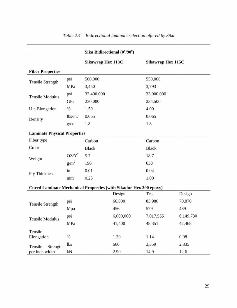
29
Table 2.4 - Bidirectional laminate selection offered by Sika
Sika Bidirectional (0o/90o)
Sikawrap Hex 113C Sikawrap Hex 115C
Fiber Properties
Tensile Strength psi 500,000 550,000
MPa 3,450 3,793
Tensile Modulus psi 33,400,000 33,000,000
GPa 230,000 234,500
Ult. Elongation % 1.50 4.00
Density lbs/in.3 0.065 0.065
g/cc 1.8 1.8
Laminate Physical Properties
Fiber type Carbon Carbon
Color Black Black
Weight OZ/Y2 5.7 18.7
g/m2 196 638
Ply Thickness in 0.01 0.04
mm 0.25 1.00
Cured Laminate Mechanical Properties (with Sikadur Hex 300 epoxy)
Design Test Design
Tensile Strength psi 66,000 83,980 70,870
Mpa 456 579 489
Tensile Modulus psi 6,000,000 7,017,555 6,149,730
MPa 41,400 48,351 42,468
Tensile
Elongation % 1.20 1.14 0.98
Tensile Strength
per inch width
lbs 660 3,359 2,835
kN 2.90 14.9 12.6

30
The term ‘adhesion’ is associated with intermolecular forces acting across an interface and
involves a consideration of surface energies and interfacial tensions. As a liquid, adhesives flow
over and into the irregularities of a solid surface, coming into contact with it and as a result,
interacting with its molecular forces. The adhesive then solidifies to form the “joint”. The basic
requirements for good adhesion are thus intimate contact between the adhesive and the substrates
and an absence of weak layers or contamination at the interface. Adhesive bonding therefore
involves a liquid ‘wetting’ a solid surface, which implies the formation of a thin film spreading
uniformly without breaking into droplets. Fundamentally, the surface tension of the adhesive
should be lower than the surface energy of the solids involved, in this case, the treated surface of
FRP and the exposed constituents of concrete. Because of the similarity in epoxy adhesive and
composite matrix composition, values of surface tension and surface energy are similar. Both
compositions contain polar molecular groups which are mutually attractive and chemically
compatible. Thus, good adhesion is assured, provided that contamination is removed by surface
preparation (Sika Corp. 2012). The quality of the adhesive bond at the interface has the potential
to impact failure modes of an FRP composite structure. The interface between the FRP sheet and
the concrete is particularly important, since composite action requires a perfect bond. Final
failure is often caused by the debonding of the FRP sheet from the concrete substrate (Meier
1995, Buyukozturk & Hearing 1998). The degradation of a constituent in FRP over time affects
various composite properties, and may even change the order of governing failure modes which
may be matrix, fiber, or interface-dominated. This is a particularly important concern, as a FRP
bonded structure could fail abruptly due to a change in dominant failure mode.
2.2.5 Current design standards and guides
Various documents have been developed in the last two decades describing FRP strengthening
systems and provide guidelines for design assumptions and calculations. The most widely known
guide in the US is ACI 440.2R, Guide for the Design and Construction of Externally Bonded
FRP Systems for Strengthening Concrete Structures (2008). A number of reports issued by the
National Cooperative Highway Research Program (NCHRP) are design/construction guides of
FRP systems and include:
NCHRP Report 678, Design of FRP Systems for Strengthening Concrete Girders in
Shear (Belarbi et al. 2011).
NCHRP Report 655, Recommended Guide Specification for the Design of Externally
Bonded FRP Systems for Repair Strengthening of Concrete Bridge Elements (Zureick et
al. 2010).
NCHRP Report 564, Field Inspection of In-Service Bridge Decks (Telang et al. 2006),
which contains a manual for the in-service inspection of FRP bridge decks.
NCHRP Report 514, Bonded Repair and Retrofit of Concrete Structures Using FRP
Composites (Mirmiran et al. 2004), which describes recommended construction
specifications and a control process for FRP strengthening including material preparation,
application, a QA/QC plan, as well as training, qualification, inspection, and maintenance
recommendations.
Other US and international guides include:

31
AASHTO (2013), Guide Specifications for Design of Bonded FRP Systems for Repair
and Strengthening of Concrete Bridge Elements.
AC125 (2012), Acceptance Criteria for Concrete and Reinforced and Unreinforced
Masonry Strengthening Using Externally Bonded Fiber-Reinforced Polymer (FRP)
Composite Systems. AC125 is issued by ICC Evaluation Service to establish minimum
requirements for the issuance of evaluation reports on fiber-reinforced polymer (FRP)
composite systems under the 2012, 2009 and 2006 International Building Code (IBC)
and the 1997 Uniform Building Code (UBC).
ACI 440.3R (2004), Guide Test Methods for Fiber-Reinforced Polymers (FRPs) for
Reinforcing or Strengthening Concrete Structures.
ACI 440R (2007), Report on Fiber-Reinforced Polymer (FRP) Reinforcement for
Concrete Structures.
ACI SP-215 (2003), Field Applications of FRP Reinforcement: Case Studies.
ISIS (2008), Design Manual No. 4, FRP Rehabilitation of Reinforced Concrete
Structures, issued by the Canadian Network of Centers of Excellence on Intelligent
Sensing for Innovative Structures.
CEB-FEB (2001), Bulletin No. 14, Externally Bonded FRP Reinforcement for RC
Structures, contains design guidelines for the use of FRP reinforcement in accordance
with the design format of the CEB-FIP Model Code and Eurocode2.
CNR-DT 200 (2004), Guide for the Design and Construction of Externally Bonded FRP
Systems.
Japanese Society of Civil Engineers (1997), Recommendations for Design and
Construction of Concrete Structures Using Continuous Fiber Reinforcing Materials.
Japan Concrete Institute (1997), State of the Art Report on Retrofitting with CFRM,
Guidelines for Design, Construction and Testing.
TCS (2000), Design Guidance for Strengthening Concrete Structures Using Fiber
Composite Materials, Technical Report 55, UK.
A decade ago, MDOT released Research Report RC-1386, Repair of Corrosion-Damaged
Columns using FRP Wraps (Harichandran and Baiyasi 2000), in which laboratory testing was
conducted to assess the results of this particular application. In 2003, MDOT issued Research
Report RC-1435, Sensors to Monitor Bond in Concrete Bridges Rehabilitated with FRP
(Harichandran and Hong 2003), in which an experimental study to detect the debonding of EB
CFRP on concrete structures was conducted using electrochemical impedance spectroscopy
(EIS) sensing technology. The goal was to assess various environmental factors on debonding.
2.2.6 Designing with FRP reinforcement
A reinforced concrete element strengthened with FRP is a member consisting of three materials,
concrete, steel, and FRP, where the FRP supplements the existing steel reinforcement. The
application of FRP requires engineers to address the interaction of the three materials, with each
material having different material properties and statistical variation. Design formulations
addressing each material’s contribution to the overall strength (Rn) of the element can be based
on either suitable overall or individual reduction factors applied separately to each of the

32
materials constituting the composite (concrete, steel and FRP), a combined reduction factor
applied to the entire composite, or a combination of the two where both individual and combined
reduction factors are applied to the system (Sika 2012). For example, ACI 440.2R-08
recommends the use of ACI-318 resistance ( ) factors applied to the overall element strength, in
combination with an additional FRP reduction factor ψ, which takes into account the effects of
FRP material property variation. The general philosophy can be expressed as: Rn = [steel &
concrete + ψ (FRP strength)].
2.2.7 Flexural strengthening
In the ACI approach, which is similar to other provisions, the nominal moment capacity of a
tension-reinforced section Mn can be obtained from eq. 1, where the first term is the moment
capacity generated from the tension steel force and the second term is the moment capacity
generated from the FRP sheet. Design capacity Mn is then determined by reducing the nominal
moment capacity by the appropriate resistance factor :
22
11 chfA
cdfAM fefssn
(2.1)
Parameter ψ represents a factor used to reduce the contribution of the FRP sheet, while other
parameters in eq. 2.1 are similar to those used in typical reinforced concrete flexural capacity
analysis (representing areas of tension material, As and Af, their stresses at section capacity, fs and
ffe, and their lever arms to the compression zone of the concrete, d-β1c/2 and h-β1c/2). A concern
is that, in a recent study (Elarbi and Wu 2012), eq 2.1. was found to typically underestimate
experimental results by 20% to 60%, which is discussed further below. However, of greater
concern is the possibility of over-estimating capacity by not properly accounting for loss of FRP
or bond strength over time, as outlined above.
An additional concern is the possibility of over-estimating capacity by not properly accounting
for loss of FRP or bond strength over time. It was observed that more reliable strength reduction
coefficients need to be developed to represent the long-term use of FRP exposed to the
environmental and service parameters specific to a local region. To better develop design
standards and construction guides, PennDOT commissioned a research program by selecting
candidate bridges for NDT testing before and after the application of EB FRP for beam
strengthening. Results from a finite element analysis of test data were used to develop draft
PennDOT design standards and construction specifications and to apply lessons learned to the
design and constructability of nearly 1,000 concrete T-beam bridges in Pennsylvania (Davalos et
al. 2012).
2.2.8 Shear strengthening
FRP sheets have been shown to increase the shear strength of existing concrete beams and
columns when used to wrap members (Chajes et al. 1995, Labossiere et al. 1995, Seible et al.
1997, Mo et al. 2004). The nominal shear strength of an FRP strengthened concrete member Vn

33
can be determined by adding the contribution of the FRP reinforcing (Vf) to the contribution of
the steel shear reinforcement (Vs) and the concrete (Vc), as per eq. 2.2, which presents the ACI
approach. The total design strength is then found by appropriately reducing Vn by the
appropriate shear resistance factor .
fscn VVVV (2.2)
The contribution of the FRP sheet to shear strength is based on fiber orientation and the assumed
shear crack pattern. The shear strength provided by the FRP reinforcement can be determined by
calculating the force resulting from the tensile stress in the FRP across an assumed crack, in a
similar fashion to the process used for design with steel stirrups. As given by ACI 440 (2007),
the shear contribution from FRP is:
f
ffeff
s
dcossinfAV
(2.3)
where Af is the cross sectional area of the FRP sheet; ffe is the tensile stress in the FRP
reinforcement; df is the effective beam height; is the orientation angle of the FRP and sf is the
spacing between adjacent FRP strips. To avoid delamination failure, mechanical anchorage can
be used. However, the effective strain in FRP is limited (for example, to 0.004 per ACI 440),
and the total shear reinforcement allowed is often limited as well. For example, FRP shear
reinforcement in ACI is limited to the same criteria given for steel alone per ACI 318 (2011),
given as: dbfVV wcfs
'8 .
2.2.9 Numerical modeling
Numerous researchers have developed numerical models of FRP-strengthened concrete elements
(Ouyang & Wan 2006, Ibrahim & Mahmood 2009, Obaidat et al. 2010, etc). Pesic and
Pilakoutas (2003) conducted a finite element analysis to address concrete cover delamination and
plate end failure of concrete beams with bonded flexural FRP reinforcement. Elarbi (2011)
developed refined models in recent research using the finite element analysis code ABAQUS, to
predict the deformation and failure of concrete beams strengthened with carbon FRP sheets
applied to the bottom surface. This approach explicitly modeled the concrete and FRP materials
with independent elements and nonlinear time-dependent material properties to account for
deterioration. The two types of expected failure modes have been correctly predicted by the
model: FRP rupture and FRP delamination. Two groups of beams were examined; one group
with perfectly bonded FRP reinforcement and another group of aged beams with deteriorated
FRP reinforcement bond. For the healthy FRP bonded beams in the study, the dominant failure
mode was FRP rupture, where the concrete first began to crack on the midpoint of the tension
side and propagated approximately one-third of the section height upwards, followed by rupture
of the FRP sheet. For the aged (bond-deteriorated) FRP bonded beams, the dominant failure
mode was delamination. FRP delamination began at the midpoint of the beam and then spread
toward the beam ends. These two failure modes predicted from the model well-matched the
observed experimental failure sequences.

34
Elarbi (2011) also conducted an extensive series of concrete beams strengthened with carbon
FRP. Beams were conditioned to simulate the aging effect that weather-exposed components are
expected to experience, and was conducted using various accelerated hygrothermal conditions.
For the control specimens exposed to indoor conditions only, it was found that the ACI-based
predictions of capacity significantly underestimated the failure load, whereas the numerical
simulations agreed well with experimental results. Similar specimens were exposed to
accelerated weathering cycles, under which bond strength deteriorated and led to delamination, a
failure which is not currently considered in ACI 440 but accounted for in the numerical
simulations.
2.2.10 Delamination
FRP delaminaton, or debonding, can be considered as the propagation of an interfacial crack
with residual shear stress acting along the interface (Taljsten 1996, Leung & Tung 2006). In the
case of FRP bonded to flat concrete members, debonding may occur at the end of the FRP sheet
or initiate at an interior location where a stress concentration is present. Once debonding
initiates, however, it may initially remain stable depending on how adjacent cracks interact,
potentially allowing for further increases in load (Niu & Wu 1990, Chen et al. 2007).
To model debonding, an interfacial shear-slip relation is generally needed. Most interfacial
relation models are based on two similar assumptions. First, the initiation of interfacial
debonding begins when the interfacial stress has reached the prescribed interfacial strength (τs).
Second, in the debonded zone, the residual shear stress (τ) softens linearly with the interfacial
sliding (s), such as given by (Leung & Tung 2006): τ = τ0 – ks, where τ0 and k are the interfacial
material parameters defining the initial residual shear stress and the shear softening rate after
debonding. Based on this equation, the distribution of tensile stress (σp) along the debonded
portion of FRP is calculated from:
2
2
20P
P
d
dx
(2.4)
Finally, in the elastic zone where debonding has not yet occurred, σp is given by:
2
2
20P
P
d
dx
(2.5)
where and are parameters describing the structural configuration and material properties.
Solving the above equations with appropriate boundary conditions provides the tensile stresses
along the FRP sheet as well as interfacial shear stresses. Such an analytic approach can simulate
the debonding process in great detail, permitting comparisons with experiments. However, such
analytical solutions are available for simple cases only.
Another popular approach to model debonding is to use finite element analysis. By using
suitable interface elements, very good results have been obtained (Wu et al. 2004, Mu et al.
2006, Elarbi & Wu 2012). This approach allows simulations of rather complex loading and

35
geometrical configurations, but does not provide a detailed description of the delamination
process. Therefore, both approaches may need to be considered to properly characterize
delamination behavior.
2.2.11 Durability
Most FRP durability information has been gathered from laboratory simulations of harsh
environments (Dutta & Hui 1996, Toutanji & Balaguru 1999, Karbhari et al. 2003). Karbhari
(2004) found that low temperature thermal cycling appears to have a greater deteriorative effect
on FRP than constant immersion at below-freezing temperatures, due in part to interface-level
degradation. Here, micro-cracking at lower temperatures results in an increase of water
absorption during warmer periods, followed by increased resin plasticization and hydrolysis.
The expansion of frozen water collected in cracks results in debonding and transverse micro-
crack growth (Rivera & Karbhari 2002). Various other researchers have found that such
freeze/thaw exposures can lead to significant material degradation through matrix cracking and
fiber-matrix debonding, as well as increased brittleness, resulting in a substantial change in the
damage mechanisms commonly observed under ambient conditions (Dutta 1989, 1992, Lord &
Dutta 1988, Haramis 2003, Karbhari et al. 1994, 2000, 2002). For glass and carbon-wrapped
columns, however, freeze-thaw cycles alone appear to have no significant effect on compressive
strength. It was also found that, using accelerated corrosion experiments, column wrapping
significantly reduced reinforcing bar corrosion (Harichandran & Baiyasi 2000).
Wu et al. (2006, 2006a) completed a comprehensive study on the combined effects of low
temperature thermal cycling, cycling frequency, sustained loads, and presence of salinity on
FRP. It was found that sustained loads significantly accelerated degradation in all cases; that the
significance of salinity depended on the cycling frequency; and that a high-humidity
environment produced most damage. Moreover, when FRP materials were conditioned at higher
temperatures, water absorption was increased under sustained loads (Gibson 1994, Kulkarni &
Gibson 2003). Elarbi and Wu (2012) recently found that high temperature and high humidity
environments have a very detrimental effect on the strength and stiffness of FRP materials, as
well as the bonding between FRP and concrete. Although experimental data on bond
deterioration due to natural weathering are unavailable, under accelerated laboratory
environments, a large reduction (more than 80%) in bond strength between FRP and concrete in
a high temperature environment has been reported, primarily due to the deterioration of the FRP
material (Bank et al. 1998, Katz et al. 1999, Galati et al. 2006).
2.2.12 Accelerated weathering testing
At present, there is no standardized durability test procedure for FRP materials for infrastructure
applications. However, an accelerated test procedure to simulate the effects of natural
weathering on FRP has been developed by Wu et al. (2006, 2006a). This procedure, modified
from ASTM C666 (2008), the standard freeze/thaw durability test for concrete, incorporates the
combined effects of temperature, medium (i.e. immersion environment), and sustained load into
a complete test program. Using this test procedure, it was found that failure modes of FRP
composites most likely to be affected by environmental conditions are those associated with the
polymer matrix material (Wu et al. 2006). It was also found that after 250 freeze/thaw cycles

36
with less than 25% sustained load applied, flexural strength of an FRP-bonded concrete
specimen experienced significant reductions if exposed to moisture (Wu et al. 2006).
Using tests similar to the above, degradation rates can be fundamentally calculated from the
change in strength or stiffness versus time plots. However, to reduce experimental time, an
accelerated test method uses one or several accelerating mechanisms to increase the rate of
degradation. The rate of degradation under the accelerated condition is then related to the
degradation rate under field service conditions by an acceleration factor, which is defined as the
ratio of the degradation rate in the accelerated environment (i.e. laboratory) to that in the actual
service environment. Acceleration factors for various environments may be determined using
the framework outlined in ASTM E632 (1996). With appropriate acceleration factors known,
short-term, relatively inexpensive laboratory experiments or FE simulations can be used to
accurately simulate durability performance over real time (Yan 2005). Thus, the acceleration
factor is a particularly valuable tool to evaluate degradation rates. Currently, however,
appropriate acceleration factors for FRP use in Michigan are unknown.
2.2.13 Installation of externally bonded FRP systems
While installation procedures are straightforward, it is well recognized that even minor deviation
from the prescribed procedures may dramatically affect the final system performance, impact
adhesion quality, and cause premature delamination or bubbling at the concrete/FRP
reinforcement interface (TRCF 1998). In many FRP composite applications, the FRP bond to
the concrete substrate is critical. If the concrete is not properly prepared prior to wrapping, the
FRP composite may not adhere adequately to the concrete surface. Surface preparation should
include removal of all contaminants such as organic growth, old bituminous products, surface
coats, oil and dirt, by high pressure water cleaning and/or sand blasting. If any of these materials
remain, there are higher risks for bond deterioration (TRCF 1998). The concrete surface should
also be dried and well cured before application of epoxy and FRP. A dry, open-pore structure in
the concrete substrate allows the epoxy primer to be drawn in, forming “legs” into the concrete
which create a mechanical anchoring bond. The concrete surface should also be free of any
impregnating sealers. A simple test can be done by sprinkling water on the substrate and check
for beading; the water should be absorbed immediately if the desired open pore structure exists.
Manufacturers of EB FRP products are aware of the importance of proper installation. Some
offer extensive training modules for contractors, while others allow installation only through
certified applicators. NCHRP 514 (2004) recommends that the manufacturer/supplier be
prequalified for each FRP system after providing product data sheets, approved product testing
data sets, and a comprehensive hands-on training program to qualify each FRP system
contractor/applicator. It further recommends that the contractor is left responsible for the quality
control of all materials and procedures in the project, and must submit a quality control and
quality assurance (QC/QA) plan for approval. The plan should include specific procedures for
personnel safety, tracking and inspection of all FRP components prior to installation, inspection
of all prepared surfaces prior to FRP application, inspection of the work in progress to ensure
conformity with specifications, QA samples, inspection of all completed work including
necessary tests for approval, repair of any defective work, and clean-up. It was further
recommended that any part of the work that fails to comply with the requirements be remedied or

37
removed and replaced by the contractor. A proper installation plan includes adequate
specification of safety procedures, equipment and materials preparation and procurement, surface
preparation, precutting of fabric, determining the correct fabric to resin ratio, proper epoxy
mixing and saturation of FRP sheets, how to properly apply the sheets to the structural member,
and applying coatings as specified (Mirmiran et al. 2004).

38
CHAPTER 3: DESIGN PROVISIONS
3.1 Introduction
This chapter presents a review and evaluation of prevalent design guidelines for the use of
externally applied FRP for strengthening reinforced concrete bridge members. Guided by the
literature review presented in Chapter 2, six international representative strengthening guidelines
covering practice in North America, Europe, and Japan were chosen for thorough investigation
of the assumptions, procedures, and limits for design and analysis. The specific guidelines
considered for review and evaluation are:
1. ACI 440.2R-08 - Guide for the Design and Construction of Externally Bonded FRP Systems
for Strengthening Concrete Structures (ACI 440.2R, 2008).
2. ISIS – Design Manual 4 - FRP Rehabilitation of Reinforced Concrete Structures (ISIS
Design Manual 4, Version 2, 2008).
3. AASHTO Guide Specification for the Design of Bonded FRP Systems for Repair and
Strengthening of Concrete Bridge Elements (AASHTO FRP Guide, 2013).
4. JSCE Recommendations for Upgrading of Concrete Structures with use of Continuous Fiber
Sheets (JSCE Recommendations, 2001).
5. TR55 - Design guidance for strengthening concrete structures using fibre composite
materials (TR55, 2000).
6. CNR-DT 200/2004 - Guide for the Design and Construction of Externally Bonded FRP
Systems (CNR-DT 200, 2004).
Note that the review is limited to practically available documents. For example, CNR/2004, had
a recent update, but this has not yet been translated to English, and thus was not included for
evaluation in this report. The scope of the review in this chapter covers the analysis and design
procedures for flexural strengthening, shear strengthening, and confinement using externally
bonded FRP wrap. For reference, relevant and available code nomenclature is given in
Appendix A.
Section 3.2 covers flexural strengthening, where the effect of concrete strength, FRP strength,
existing steel reinforcement ratio, and other critical parameters, are considered for comparison
among guidelines. Section 3.3 covers shear strengthening, where cases of continuous and spaced
U-wrap, complete wrap, and two-sided strips are considered. Section 3.4 covers confinement,
with consideration given to circular and square columns.
3.2 Flexural FRP Strengthening of RC/PC Bridge Members
3.2.1 Introduction
The items considered for review and comparison in this section are based on the ACI 440.2R-08
framework since it offers the most complete coverage of the subject. These specific items
include:

39
Strengthening limits
Environmental reduction factors
FRP strain limits
Strength reduction factors
Serviceability and service load limits
Creep rupture and fatigue limits
FRP end peeling and development length
Flexural design approach and assumptions
Nominal moment analysis and design procedure
The use of FRP strengthening systems can substantially enhance flexural strength. It has been
documented that an increase in flexural strength from 10% to 160% can be obtained from FRP
strengthening (Meier and Kaiser, 1991; Ritchie et al, 1991; Sharif et al, 1994). However, taking
into account code-specified strengthening and ductility limits, strength increases of 40% are
more reasonable.
3.2.2 Strengthening Limits
AASHTO, ACI, and ISIS set strengthening limits to qualify a structural member for
strengthening. The limits ensure the member’s ability to support a specified amount of service
dead and live loads in the case of loss of strengthening due to construction error, severe
environmental damage, vandalism, or fire (ACI 440.2R, 2008). Other guides emphasize the need
for a thorough inspection of the existing structure, and a review of plans and specifications, the
as-built plans, as well as any repair/maintenance documentation of the structure. Unlike
AASHTO, ACI and ISIS, other guides leave the decision to strengthen a structure to the
responsible agency on a case by case basis. The following paragraphs present strengthening
limits specified by AASHTO, ACI, and ISIS.
3.2.2.1 AASHTO
The provisions of AASHTO are limited to concrete members with a specified compressive
strength not exceeding 8 ksi and apply to bridge elements for which the factored resistance
satisfies the following requirement (AASHTO LRFD Bridge Specifications, 5th
Edition):
(3.2.1)
where:
= factored resistance
DC = load effect due to component and attachments
DW = load effect due to wearing surfaces and utilities
LL = live load effect
IM = force effect due to dynamic load allowance
= load modifier calculated using the following expression:

40
(3.2.2)
where:
= a factor relating to ductility;
≥ 1.05 for non-ductile components and connections
= 1.00 for conventional designs and details complying with the AASHTO LRFD
Specifications
≥ 0.95 for components and connections for which additional ductility-enhancing
measures have been specified beyond those required
For all other limit states: = 1.00
= a factor relating to redundancy
≥ 1.05 for non-redundant members
= 1.00 for conventional levels of redundancy
≥ 0.95 for exceptional levels of redundancy
For all other limit states: = 1.00
= a factor relating to operational classification
≥ 1.05 for critical or essential bridges
= 1.00 for typical bridges
≥ 0.95 for relatively less important bridges
For all other limit states: = 1.00
Note that the resistance of components and connections is determined, in many cases, on the
basis of inelastic behavior, although the force effects are determined by using elastic analysis.
This inconsistency is common to most current bridge specifications as a result of incomplete
knowledge of inelastic structural action.
3.2.2.2 ACI 440.2R-08
Similar to AASHTO, ACI sets limits to qualify a structure for strengthening. Here, two
conditions must be met. The first condition is expressed by Equation 3.2.3 (ACI Equation 9.1) to
ensure the structure’s ability to sustain a minimum specified load after loss of strengthening
Equation 3.2.3 states that the existing structural design capacity must equal or exceed the new
service dead load by at least 10%, and must have the ability to support at least 75% of the new
service live loads.
(φRn)existing ≥ (1.1SDL + 0.75SLL)new (3.2.3 – ACI Eq. 9.1)
(φRn)existing ≥ (1.1SDL + 1.00SLL)new (3.2.4)

41
To be considered for strengthening, a structural member must also meet the condition expressed
by Equation 3.2.5 (ACI Equation 9.2), which ensures the structure is able to sustain load for the
duration of its fire rating in the case of fire. The quantity represents the nominal strength at
elevated temperature in accordance with the guidelines of ACI 216R (ACI 216R-1989) or
through testing. Fire scenarios considered should be in accordance with ASTM E119 (ASTM
E119). The value is to be computed for the structure’s fire rating without considering the
strength contribution from FRP. Figure 3.2.1 shows the required minimum relationship between
and the desired service live load, for various levels of existing dead load.
(3.2.5 - ACI Eq. 9.2)
Figure 3.2.1 - ACI strengthening limits at elevated temperatures
3.2.2.3 ISIS
ISIS Design Manual 4 (Canada) recommends that an existing structure have the capacity to
support dead loads and at least 50% of its live loads to qualify for strengthening (note although
ISIS describes the requirement, it does not provide an explicit expression). The ISIS condition
for strengthening may be expressed in a manner similar to that of ACI, as presented by Equation
3.2.6.
( )existing ≥ (1.0 + 0.5 )new (3.2.6)
The ISIS condition given above is specific to the S6-06 Canadian bridge code (CSA-S6-06,
2006). The live load factor of 0.5 serves as a minimum limit, but ISIS notes that it is subject to
increase.
0
100
200
300
400
500
600
0 50 100 150 200 250 300
DL = 50 psf
DL = 100 psf
DL = 150 psf
DL = 200 psf
DL = 250 psf
Service Live Load, psf
Exis
tin
g St
ruct
ure
No
min
al
Res
ista
nce
, R
nθ ,
psf

42
3.2.2.4 Other Codes
The UK Concrete Society Standard TR55 offers no specific quantitative expression as a set
criterion to qualify a structure for strengthening. However, it states that the decision to strengthen
should be guided by a careful assessment process that is independent of structure type and based
on rigorous criteria and sound engineering judgment. TR55 refers to TR54 -Diagnosis of
deterioration in concrete structures (TR54, 2000) and the Institution of Structural Engineers’
Appraisal of Existing Structures (1996) for assistance in evaluating the condition of the structure.
Italy’s CNR presents factors to consider that insure the durability of the member to be
strengthened, while JSCE offers no specific quantitative expression or condition to serve as set
criterion to qualify a structure for strengthening.
3.2.2.5 Summary
To illustrate the difference between the above strengthening limits, consider a case where the
new service dead load (SDL) is to be 50 psf and the new service live load (SLL) is to be 140 psf. In
this case, ACI limits strengthening to members that can support a minimum existing capacity of
160 psf, and, if fire is considered, the member must be able to sustain 190 psf. In contrast, the
ISIS minimum load capacity is 120 psf.
Figure 3.2.2 presents a comparison of ACI, AASHTO, and ISIS strengthening limits. Note that
ACI offers two scenarios, one for sustained live loads (generally not applicable to most bridges),
and another for a typical transient live load. From the graph, it can be seen that AASHTO and
ACI adopt similar limits for strengthening while ISIS is less conservative. The ACI fire
endurance limit appears similar to the exiting strengthening limit provided by of AASHTO.
Therefore, no special fire endurance condition appears needed and AASHTO provisions are
recommended for use.
In summary, AASHTO and ACI have similar strengthening limits, where ISIS allows
strengthening at a lower threshold of existing structure strength. As the LL/DL ratio increases,
with differences increasing significantly while the remaining codes do not quantify strengthening
limits.
3.2.3 Environmental Reduction Factors
Environmental factors are applied to FRP material properties to account for degradation in
exposure conditions, as a function of exposure as well as FRP material and application.
3.2.3.1 ACI
ACI indicates that the values presented in Table 3.2.1 below (ACI Table 9.1) are conservative
and based on the relative durability of each fiber type.

43
Figure 3.2.2 - FRP strengthening limits for different codes (with fixed dead load of 50 psf)
Table 3.2.1 – Environmental reduction factors
Exposure Conditions Fiber type Environmental
reduction factor CE
Interior exposure
Carbon 0.95
Glass 0.75
Aramid 0.85
Exterior exposure
(bridges, piers, and unenclosed
parking garages)
Carbon 0.85
Glass 0.65
Aramid 0.75
Aggressive environment
(chemical and wastewater treatment
plants)
Carbon 0.85
Glass 0.50
Aramid 0.70
3.2.3.2 CNR
The CNR code (Italy) recommends an environmental conversion factor ηa with values identical
to those presented in the ACI standards above. The factor ηa is used to determine the maximum
FRP design strain, , defined as:
(3.2.7)
0
50
100
150
200
250
300
350
0 50 100 150 200 250 300
AASHTO
ACI
ISIS
ACI-2
Exis
tin
g St
ruct
ure
Cap
acit
y, p
sf
Service Live Load, psf

44
Generally, is the minimum governing value. Therefore, the environment factor usually does
not govern the design. See Table 3.2.2 for values of (Table 3.2.2 - CNR Table 3-4).
Table 3.2.2 – Environmental conversion factor
3.2.3.3 ISIS
ISIS does not directly specify an environmental reduction factor. Rather, ISIS considers
“material resistance factors”, which include an environmental reduction factor along with other
partial safety factors combined in a single factor. ISIS presents two sets of factors depending on
the code used; one for bridges and another for buildings. In this document, greater consideration
is given to the Canadian bridge code S6-06 (CSA-S6-06, 2006) recommendations. Factors are
developed based of several criteria including type of material, type of manufacturing process,
and other durability and environmental considerations, as shown in Table 3.2.3 below (ISIS
Table 3.3.4). Note that the reduction factor specific to pultruded CFRP (hand applied wet lay-up)
is 0.56, which is considerably conservative compared to AASHTO’s 0.85 reduction factor.
Table 3.2.3 - Material resistance factors Material (installation process) Bridges Buildings
Pultruded Aramid FRP (NSMR) 0.60 --
Pultruded Aramid FRP (externally-bonded plate) 0.50 0.75
Aramid FRP sheet (hand applied wet lay-up) 0.38 0.75
Pultruded Carbon FRP 0.75 0.75
Carbon FRP sheet (hand applied wet lay-up) 0.56 0.75
Pultruded Glass FRP 0.65 0.75
Glass FRP sheet (hand applied wet lay-up) 0.49 0.75
Concrete 0.75 0.60
Steel (passive reinforcement) 0.95 0.85
Steel (prestressing tendons) 0.95 0.90
Exposure Conditions Type of fiber/resin
Internal Glass/Epoxy 0.75
Aramid/Epoxy 0.85
Carbon/Epoxy 0.95
External Glass/Epoxy 0.65
Aramid/Epoxy 0.75
Carbon/Epoxy 0.85
Aggressive environment Glass/Epoxy 0.50
Aramid/Epoxy 0.70
Carbon/Epoxy 0.85
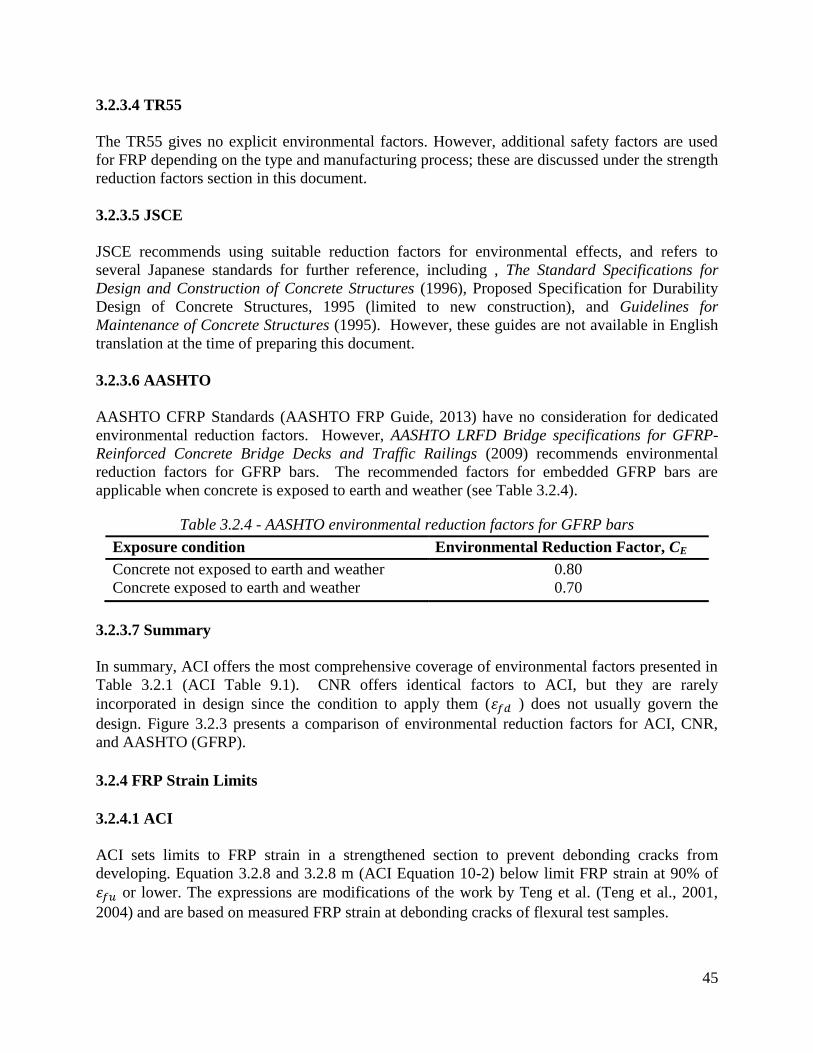
45
3.2.3.4 TR55
The TR55 gives no explicit environmental factors. However, additional safety factors are used
for FRP depending on the type and manufacturing process; these are discussed under the strength
reduction factors section in this document.
3.2.3.5 JSCE
JSCE recommends using suitable reduction factors for environmental effects, and refers to
several Japanese standards for further reference, including , The Standard Specifications for
Design and Construction of Concrete Structures (1996), Proposed Specification for Durability
Design of Concrete Structures, 1995 (limited to new construction), and Guidelines for
Maintenance of Concrete Structures (1995). However, these guides are not available in English
translation at the time of preparing this document.
3.2.3.6 AASHTO
AASHTO CFRP Standards (AASHTO FRP Guide, 2013) have no consideration for dedicated
environmental reduction factors. However, AASHTO LRFD Bridge specifications for GFRP-
Reinforced Concrete Bridge Decks and Traffic Railings (2009) recommends environmental
reduction factors for GFRP bars. The recommended factors for embedded GFRP bars are
applicable when concrete is exposed to earth and weather (see Table 3.2.4).
Table 3.2.4 - AASHTO environmental reduction factors for GFRP bars Exposure condition Environmental Reduction Factor, CE
Concrete not exposed to earth and weather
Concrete exposed to earth and weather
0.80
0.70
3.2.3.7 Summary
In summary, ACI offers the most comprehensive coverage of environmental factors presented in
Table 3.2.1 (ACI Table 9.1). CNR offers identical factors to ACI, but they are rarely
incorporated in design since the condition to apply them ( ) does not usually govern the
design. Figure 3.2.3 presents a comparison of environmental reduction factors for ACI, CNR,
and AASHTO (GFRP).
3.2.4 FRP Strain Limits
3.2.4.1 ACI
ACI sets limits to FRP strain in a strengthened section to prevent debonding cracks from
developing. Equation 3.2.8 and 3.2.8 m (ACI Equation 10-2) below limit FRP strain at 90% of
or lower. The expressions are modifications of the work by Teng et al. (Teng et al., 2001,
2004) and are based on measured FRP strain at debonding cracks of flexural test samples.

46
Figure 3.2.3 - Comparison of environmental reduction factors
(3.2.8 – ACI Eq. 10.2)
(3.2.8 m – ACI Eq. 10.2)
The ACI code notes that transverse clamping of flexural samples has shown to improve bond
behavior relative to that predicted by Equation 3.2.8 (ACI Eq. 10.2). Provision of transverse
clamping FRP U-wraps along the length of flexural FRP reinforcement has been observed to
increase FRP debonding strain by up to 30% (CECS- 146, 2003) prior to debonding failure.
To illustrate the condition expressed in Equation 3.2.8, assume a 4000 psi concrete beam
strengthened with 3 plies of BASF MBRACE CF130 CFRP, where the thickness per ply is
0.0065 inch. Further assuming tensile properties as: ultimate tensile strength, 550 ksi;
tensile modulus, Ef = 33,000 ksi; ultimate rupture strain, 1.67%; nominal thickness, tf =
0.0065 in/sheet. The application of Equation 2.8 (ACI Eq. 10-2) results in FRP strain being
limited to 0.0065 in/in, which is 46% of the ultimate FRP strain value of 0.0142 in/in.
3.2.4.2 ISIS
ISIS considers debonding and anchorage failures as premature tension failures that require
evaluation to reduce on a case by case basis through testing. However, the Code specifies a
maximum value of 0.006 as specified by the building code S806-02 (CAN/CSA-S806-
02, 2002).
0.95
0.85
0.7
0.8
0.0
0.1
0.2
0.3
0.4
0.5
0.6
0.7
0.8
0.9
1.0
CFRP-Interior Exposure CFRP-Exterior Exposure & Aggressive Environment
GFRP-Concrete not exposed to earth and
weather
GFRP-Concrete exposed to earth and weather
ACI CNR
ACI CNR AASHTO AASHTO

47
3.2.4.3 AASHTO
AASHTO requires that the strain developed in the FRP reinforcement at the ultimate limit state
shall be equal to or greater than 2.5 times the strain in the FRP reinforcement at the point where
the steel tension reinforcement yields (Equation 3.2.9). This limitation is present to ensure that
the tension steel reinforcement yields before the point of incipient debonding of the externally
bonded FRP reinforcement, thereby enabling the development of a ductile mode of flexural
failure.
≥ 2.5 (3.2.9)
With a maximum useable strain of 0.005 at the FRP reinforcement/concrete interface, the
maximum strain developed in the FRP reinforcement is (Equation 2.10):
(3.2.10)
where:
= The initial tensile strain at the bottom concrete surface as a result of the moment due to
dead load (the existing tensile strain prior to FRP installation).
3.2.4.4 TR55
For strain limits, TR55 refers to Neubauer and Rostasy (1997), who suggest an ultimate limit of
5 or half the ultimate plate strain, which for the materials tested was 0.75%. TR55 further
suggests that other research has suggested somewhat lower limits, in the order of 0.6% for
sagging moments and 0.4% for hogging moments. However, practical experience in the UK
suggests that the higher strain limits are more reasonable. On this basis, TR55 recommends that,
to avoid debonding failure, the strain in the FRP should not exceed 0.8% when the applied
loading is uniformly distributed, and 0.6% if combined high shear forces and bending moments
are present, such as where the load is concentrated at a point and at hogging regions close to
supports.
3.2.4.5 CNR
Within CNR, the maximum FRP tensile strain, , is calculated as follows:
(3.2.12)
where:
characteristic value of the adopted strengthening system
environmental factor
partial factor for FRP rupture
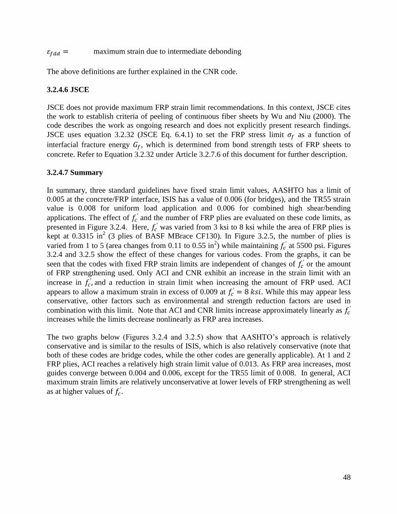
48
maximum strain due to intermediate debonding
The above definitions are further explained in the CNR code.
3.2.4.6 JSCE
JSCE does not provide maximum FRP strain limit recommendations. In this context, JSCE cites
the work to establish criteria of peeling of continuous fiber sheets by Wu and Niu (2000). The
code describes the work as ongoing research and does not explicitly present research findings.
JSCE uses equation 3.2.32 (JSCE Eq. 6.4.1) to set the FRP stress limit as a function of
interfacial fracture energy , which is determined from bond strength tests of FRP sheets to
concrete. Refer to Equation 3.2.32 under Article 3.2.7.6 of this document for further description.
3.2.4.7 Summary
In summary, three standard guidelines have fixed strain limit values, AASHTO has a limit of
0.005 at the concrete/FRP interface, ISIS has a value of 0.006 (for bridges), and the TR55 strain
value is 0.008 for uniform load application and 0.006 for combined high shear/bending
applications. The effect of and the number of FRP plies are evaluated on these code limits, as
presented in Figure 3.2.4. Here, was varied from 3 ksi to 8 ksi while the area of FRP plies is
kept at 0.3315 in2 (3 plies of BASF MBrace CF130). In Figure 3.2.5, the number of plies is
varied from 1 to 5 (area changes from 0.11 to 0.55 in2) while maintaining
at 5500 psi. Figures
3.2.4 and 3.2.5 show the effect of these changes for various codes. From the graphs, it can be
seen that the codes with fixed FRP strain limits are independent of changes of or the amount
of FRP strengthening used. Only ACI and CNR exhibit an increase in the strain limit with an
increase in and a reduction in strain limit when increasing the amount of FRP used. ACI
appears to allow a maximum strain in excess of 0.009 at . While this may appear less
conservative, other factors such as environmental and strength reduction factors are used in
combination with this limit. Note that ACI and CNR limits increase approximately linearly as
increases while the limits decrease nonlinearly as FRP area increases.
The two graphs below (Figures 3.2.4 and 3.2.5) show that AASHTO’s approach is relatively
conservative and is similar to the results of ISIS, which is also relatively conservative (note that
both of these codes are bridge codes, while the other codes are generally applicable). At 1 and 2
FRP plies, ACI reaches a relatively high strain limit value of 0.013. As FRP area increases, most
guides converge between 0.004 and 0.006, except for the TR55 limit of 0.008. In general, ACI
maximum strain limits are relatively unconservative at lower levels of FRP strengthening as well
as at higher values of .

49
Figure 3.2.4 - Effect of concrete compressive strength
on FRP strain limits (number of FRP
layers = 3, area = 0.33 in2
)
Figure 3.2.5 - Effect of amount of FRP strengthening on FRP strain limits,
=5.5 ksi
3.2.5 Strength Reduction Factors
3.2.5.1 ACI
ACI follows the approach of ACI 318-05 philosophy in evaluating the strength reduction factor
to promote ductile behavior. According to ACI 318-05, the strength reduction factor is
applicable for steel grades with yield stress up to 60 ksi. The factor is a general factor applied to
concrete, steel, and FRP equally. A maximum value of 0.9 is used when steel strain ≥ 0.005 at
0.000
0.001
0.002
0.003
0.004
0.005
0.006
0.007
0.008
0.009
0.010
3 . 0 4 . 0 5 . 0 6 . 0 7 . 0 8 . 0
UK ACI AASHTO CNR ISIS
Compressive Strength, 𝑓𝑐′, , ksi
FRP
Str
ain
Lim
it

50
ultimate capacity (i.e. when concrete has a strain value of 0.003 in compression), which
represents a tension controlled failure characterized by ductile behavior. A minimum value of
0.65 is used when ≤ , signifying a compression controlled failure (non-ductile behavior).
values follow a linear transition between the 2 extremes (see Equation 3.2-11 below). is
applied to all moment components equally; it is considered a global factor.
(3.2.11 –ACI Eq. 10-5)
As observed, the values for depend on the steel strain level. Another recommended reduction
factor specific to the FRP moment contribution is , with a value of 0.85. The combined
reduction factor for the FRP moment contribution is x . is a reduction factor to account
for the uncertainty in the FRP-generated moment strength. Uncertainty is attributed variation in
material properties and possible different failure modes observed for FRP-strengthened members
(delamination of FRP reinforcement). The reduction factor is determined based on a statistical
evaluation of variability in mechanical properties, predicted versus full-scale test results, and
field applications. The FRP-related reduction factors are calibrated to produce reliability indices
(β) typically above 3.5. However, reliability indices between 3.0 and 3.5 can be encountered in
cases where relatively low ratios of steel reinforcement combined with high ratios of FRP
reinforcement are used (Nowak and Szerszen, 2003; Szerszen and Nowak, 2003). Such cases are
less likely to be encountered in design because they violate the strength increase limits of ACI
Article 9.2 – Strengthening Limits.
Research conducted by Okeil (Okeil et al., 2007) presents the development of a resistance model
for reinforced concrete bridge girders flexurally strengthened with externally bonded CFRP
laminates. The resistance model is used to calculate the reliability index of CFRP strengthened
cross-sections. From the mode, the reliability index for CFRP strengthened sections is greater
than that for RC sections. This is primarily attributed to the low coefficient of variation for CFRP
ultimate strength, which is lower than the coefficient of variation of the strength of steel or
concrete. However, although reliability index improves with addition of CFRP, the flexural
resistance of RC members strengthened with FRP is recommended to be reduced by 0.85 over a
similar non-strengthened member. This recommendation is based on the recognition of the brittle
nature of CFRP behavior.
3.2.5.2 ISIS
As noted earlier, ISIS combines various factors into “material resistance factors” which serve to
account for resistance uncertainties as well as environmental reduction factors. ISIS presents two
sets of factors, one for bridges and another for buildings. The factors provided are also classified
by the FRP installation process, as shown in Table 3.2.3 (ISIS Table 3.4). The Table presents
material resistance factors for concrete, steel, and several FRP schemes. The ISIS factors are
applied separately to different materials.

51
The ISIS reduction value for carbon sheets using a wet lay-up is 0.56 for bridge applications and
0.75 for building applications. The ISIS low values are partially due to the fact that they
represent the multiplication of 3 equivalent factors in ACI, namely CE, , . ISIS refers to
clauses in the S6-06 bridge code (Clauses 16.5.3 and 8.4.6) (CSA-S6-06, 2006) for further
reference.
Table 3.2.5 below compares the resulting CFRP factor for a hand applied wet lay-up between
ACI and ISIS, the latter of which results in a more conservative value.
Table 3.2.5 - ISIS and ACI reduction factor comparison
Type ACI ISIS
Environmental exterior exposure, CE 0.85
0.56 Additional reduction Factor, y 0.85
0.90
Equivalent factor 0.65 0.56
3.2.5.3 AASHTO
AASHTO uses a fixed-value strength reduction factor with a value of 0.85, for externally
applied FRP. Note that the AASHTO strain limit is 0.005 for FRP, which limits the use of FRP
to flexural members which will have relatively ductile failure conditions. In contrast, for
comparison, in the case of internal GFRP bars used to reinforce bridges, AASHTO specifies the
following values for :
(3.2.13)
In which:
(3.2.14)
where:
= GFRP reinforcement ratio = / bd
Factor taken as 0.85 for concrete strength not exceeding 4 ksi. For concrete strengths
exceeding 4 ksi, is reduced at a rate of 0.05 for each 1 ksi of strength in excess of 4 ksi,
except that is not be taken less than 0.65
specified compressive strength of concrete, ksi
design tensile strength of GFRP bars considering reduction for service environment, ksi

52
Modulus of elasticity of GFRP reinforcement, ksi
Ultimate strain in concrete
GFRP reinforcement ratio producing balanced strain conditions
Figure 3.2.6 - Strength reduction factor for GFRP (adopted from AASHTO GFRP manual)
In ASSHTO GRRP, resistance factors for shear are to be taken as 0.75. If concrete strength is
higher than specified, the member can fail due to GFRP rupture. To find a transition between two
values of a section controlled by concrete crushing is defined as a section in which ≥ 1.4
, and a section controlled by GFRP rupture is defined as one in which .
3.2.5.4 TR55
In TR55 (UK), the characteristic material properties are divided by appropriate partial safety
factors ( , , ) to determine the appropriate design values. is a factor based on the
type of material used; relates to the strengthening system and method of application, and
addresses the effect of material stiffness deterioration with time. The product of the three
factors, ( . . ), determines the final safety factor. Thus:
/ ( . . ) (3.2.15 –TR55 Eq. 5.2)
Where the values of ( , , ) are determined from Tables 3.2.6, 3.2.7, and 3.2.8 (TR55
Tables 5.2, 5.3, and 5.4):
1.4
0.65
0.55
Failure by Concrete Crushing Failure
by GFRP
Rupture

53
Table 3.2.6 - Example partial safety factors for strength at ultimate limit state (TR55 Table 5.2)
Material Partial Safety Factor,
Carbon
FRP
1.4
Aramid
FRP
1.5
Glass FRP 3.5
Table 3.2.7- Recommended partial safety factors for manufactured composites (TR55 Table 5.3)
Type of system (and method of
application or manufacture)
Additional partial
safety factor, (
Plates
Pultruded
Prepreg
Performed
1.1
1.1
1.2
Sheets or tapes
Machine-controlled application
Vacuum infusion
Wet lay-up
1.1
1.2
1.4
Prefabricated (factory-made) shell
Filament winding
Resin transfer molding
Hand lay-up
Hand-held spray application
1.1
1.2
1.4
2.2
Table 3.2.8- partial safety factor for modulus of elasticity at ultimate (TR55 Table 5.4)
Material Factor of safety
Carbon FRP
Aramid FRP
Glass FRP
1.1
1.1
1.8
The product , labeled , is a partial safety factor applied to the characteristic
mechanical properties of the FRP system (Equation 3.2.16). The partial safety factor is a
function of the type of FRP material ( ), and the manufacturing process ( ).
. (3.2.16 –TR55 Eq. 5.3)
The guide provides examples of how equation 3.2.16 (TR55 Eq. 5.3) is applied using the above
tables. For example, for a carbon fiber pultruded plate, strength measured on the plate,
1.4 x 1.1 = 1.54; for an aramid sheet, strength measured on in situ specimens, 1.5 x 1.4 =
2.1; for a glass prefabricated shell, made by hand lay-up, 3.5 x 1.4 = 4.9.

54
In order to facilitate comparison of TR55 partial safety factors to strength reduction factors of
other codes, the reciprocal values, (1/x), for TR55 are considered as an equivalent reduction
factors. Figure 3.2.7 presents the equivalent reduction factors corresponding to values in
Table 3.2.6. Figure 3.2.8 presents equivalent reduction factor values corresponding to of
three select manufacturing processes from Table 3.2.7. Figure 3.2.9 presents equivalent
reduction factors corresponding to calculated values discussed in the previous paragraph.
Figure 3.2.7 - Equivalent reduction factors corresponding to material partial safety factors,
or ultimate strength limit state
Figure 3.2.8 - Equivalent reduction factors corresponding to manufacturing process partial
safety factors, or select processes
Figure 3.2.9 - Equivalent reduction factors corresponding to of select materials and
manufacturing processes
0.71 0.67
0.29
0.00
0.20
0.40
0.60
0.80
Carbon FRP Armaid FRP Glass FRP
0.91
0.71
0.45
0.00
0.20
0.40
0.60
0.80
1.00
Plate Pultruded Wet lay-up Hand-held spray application
0.65
0.48
0.13
0.00
0.20
0.40
0.60
0.80
Carbon FRP X Plate Pultruded
Armaid FRP X Wet lay-up
Glass FRP X Hand-held spray application

55
3.2.5.5 CNR
CNR specifies a partial safety factor, , that depends on the resistance model; either bending,
shear, or confinement. These factors are applicable to ultimate limit states as presented in Table
3.2.9 (CNR Table 3-3).
Table 3.2.9 - CNR partial safety factor
Resistance model
Bending/Combined bending and axial load 1.0
Shear/Torsion 1.2
Confinement 1.1
Other partial factors include materials and products factors with values that depend on failure
mode; either FRP rupture or FRP debonding. Values of are depending of application type;
type A or type B. Type A applies to certified strengthening systems, while type B applies to
uncertified strengthening systems. Certification of a strengthening system must be in accordance
with CNR acceptance criteria stipulated in section 2.5 of the code (CNR-DT 200, 2004). Values
of are presented in Table 3.2.10.
Table 3.2.10 – CNR partial factor for materials and products,
Failure mode Partial factor Type-A application1 Type-B application
2
FRP rupture 1.10 1.25
FRP debonding 1.20 1.50
In the case of FRP wet lay-up systems, CNR considers the coefficients and . is a
reduction factor for stiffness, while is a reduction factor for FRP tensile strength which
should not exceed 0.90. In design applications, CNR considers partial safety factors of 1.15,
1.60, and 1.20 for steel, concrete, and FRP respectively. The reciprocals of the partial safety
factors are considered equivalent reduction factors for steel, concrete, and FRP:
Steel equivalent reduction factor = 0.87
Concrete equivalent reduction factor = 0.63
FRP equivalent reduction factor = 0.83
3.2.5.6 Summary
FRP strength reduction factor values are near 0.85 for the majority of codes. Certain codes offer
separate factors depending of the material and manufacturing process used as in the cases of ISIS
(Canada) and TR55 (UK). Depending on the manufacturing process, the factors considered by
ISIS and TR55 are more conservative when compared to the fixed FRP reduction factor value for
ASSHTO (0.85), and values considered by ACI. The multiplicative factors specified by TR55
and CNR can result in relatively large reductions in strength. The ACI resistance factor varies
with the mode of failure and ductility. Depending on the application, ACI provides a more
conservative strength reduction factor when compared with the fixed AASHTO factor of 0.85,

56
but AASHTO is more restrictive with maximum FRP design strain. Table 3.2.11 summarizes
the FRP reduction factors specified by various codes. Table 3.2.12 summarizes commonly used
reduction factors of concrete, steel, and CFRP. Blank rows in the tables indicate non-applicable
cases for the code considered.
Table 3.2.11 – Strength reduction factors with and without environmental factor
Code Application
Reduction Factor
including
environmental factor
Reduction Factor
excluding
environmental factor
ACI
Interior Exposure
Includes CE and 0.81
0.85 Exterior Exposure
Includes CE, , and 0.72
ISIS CFRP Sheet-Wet Lay-up 0.56
CFRP Plate-Wet Lay-up 0.75
AASHTO Fixed value for FRP 0.85
TR55
CFRP Wet Lay-up sheets
(equiv.) 0.65
CFRP Wet Lay-up pultruded
plates (equiv.) 0.83
CNR Fixed value for FRP 0.83
Table 3.2.12 - Reduction factor values for concrete, steel and CFRP ACI AASHTO ISIS UK CNR
Steel 0.9≥ ≥0.65
1.0≥ ≥0.65
0.90 Non-prestressed 0.87 0.87
0.95 Prestressed
Concrete 0.75 0.67 0.80
CFRP 0.85 0.85 0.56 Sheet-hand applied
0.65 0.83 0.75 Pultruded
3.2.6 Serviceability and Service Load Limits
3.2.6.1 ACI
For non-prestressed concrete members, ACI restricts stresses in reinforcing steel and concrete
under service loads to avoid the development of inelastic deformation, especially when structures
are subject to cyclic loading. The service limits for steel as well as concrete stresses are provided
in Equations 3.2.17 and 3.2.18.
(3.2.17 - ACI Eq. 10-6)
(3.2.18 - ACI Eq. 10-7)

57
Under service loads, the stress in steel can be computed using equation 3.2.19 (ACI Eq. 10-14),
and the stress in the FRP strengthening system can be computed using equation 3.2.20 (ACI Eq.
10-15). The values calculated are compared to the service stress limits found in equations 3.2.17
and 3.2.18 (ACI Eqs. 10-6 and 10-7) to verify if serviceability conditions are met.
(3.2.19 - ACI Eq. 10-14)
(3.2.20 - ACI Eq. 10-15)
ACI does not provide references for equations 3.2.17 and 3.2.18 (ACI Eqs. 10-6 and 10-7).
3.2.6.2 AASHTO
AASHTO references AASHTO LRFD Bridge Design Specifications, 2010, for more detail on the
load combinations specific to different limit states including serviceability, strength, extreme
events and fatigue. Recommended values for AASHTO service stress limits are provided in
Table 3.2.13 below.
3.2.6.3 ISIS
ISIS specifies no limits on concrete stresses under service loads, but stipulates that the stress in
steel reinforcement under service loads may not exceed 80% of the yield stress, which is similar
to ACI limit.
3.2.6.4 TR55
TR55 references BS 8110, part 2, 1985, or BS 5400, Part 4, 1990, for crack width limits not to be
exceeded under service loads. A procedure to calculate crack width is referenced to Part 2 –
section 3 of BS 8110, 1985. To avoid excessive deformations in bridges, the stresses in the steel
reinforcement and concrete at working loads should not normally exceed 0.81 and 0.6 (or
0.6 times the worst credible strength), respectively.
3.2.6.5 CNR
CNR specifies that when investigating a service limit state, stresses in the FRP system shall
satisfy the limitation of:
(3.2.21)
where:
= the FRP characteristic strength at failure.

58
η = a factor for environmental effects, long term effects, impact and explosive loadings and
vandalism
CNR also specifies that the service stress in concrete and steel must be in accordance with limits
stated in the current building code (CNR-DT 200, 2004).
3.2.6.6 JSCE
According to JSCE, cracks in FRP-strengthened members are relatively more dispersed than in
unstrengthened members, and accordingly, the individual crack width is reduced. In pull-out
tensile strength tests of members strengthened with CFRP sheets, the crack width is proportional
to the average strain of the sheet and reinforcement, and is almost independent of the concrete
cover, the steel rebar diameter, the rigidity of the continuous fiber sheets, and the compressive
strength of concrete. At the level just before the steel yield point, the crack width is
approximately 0.3 to 0.7 times the width of cracks in members not bonded with FRP.
For structures with large dead loads, JSCE recommends that crack width be calculated using
Equation 7.4.1 of the Standard Specifications for Design and Construction of Concrete
Structures (Design), 1996. The equation proposed is identical to Equation 3.2.22 below, but
without the (0.7) multiplier.
For the specific case of large dead load, and the absence of concrete cracking prior to the
application of FRP, or for structures governed by live loads, the flexural crack width may be
calculated using Equation 3.2.22 (JSCE Eq. C6.5.1), in which the crack width is taken as 70% of
the width calculated from Equation 7.4.1.
(3.2.22 - JSCE Eq. C6.5.1)
3.2.6.7. Summary
The service stress limits for different codes are summarized in the Table 3.2.13. The same steel
limit is shared by all standards except JSCE and CNR codes. AASHTO and CNR allow the
highest FRP limits, while ACI specifies the lowest.
Table 3.2.13 - Summary of service limit state
ACI AASHTO ISIS UK CNR
Steel 0.80fy 0.80fy 0.80fy 0.80fy
Concrete 0.45f'c 0.36f'c 0.60fcu
CFRP 0.55ffu 0.80ffu 0.65 0.80ffu

59
3.2.7 Creep Rupture and Fatigue Stress Limits
3.2.7.1 ACI
According to ACI, of the available fiber types, CFRP is least affected by creep rupture. After
500,000 hours which ACI roughly equates to “about 50” years (actually 57), CFRP is predicted
to maintain 90% of its initial ultimate stress (Yamaguchi et al. 1997; Malvar 1998). The values
for GFRP and AFRP are 30% and 50% of the CFRP limit, respectively. Taking 0.6 as a safety
factor (ACI 440.2R), the limit values for GFRP, AFRP, and CFRP are 20%, 30%, and 55% as
shown in Table 3.2.14 below.
Table 3.2.14 – ACI sustained plus cyclic service load stress limit in FRP reinforcement
Fiber type
GFRP AFRP CFRP
0.20ffu 0.30ffu 0.55ffu
The tabulated limits in Table 3.2.14 represent fiber stress limits under service conditions . An
evaluation of using Equation 3.2.20 must be less or equal the tabulated limit in Table 3.2.14.
3.2.7.2 ISIS
ISIS provisions to guard against fatigue failure include limits on the difference between
maximum and minimum stresses in the steel bars to 125 MPa (CAN/CSA S6-06 bridge code,
2006). ISIS imposes limits on the service stresses providing different limits for bridges and
buildings to protect against creep rupture. Table 3.2.15 (ISIS Table 5.1) below presents these
limits for AFRP, CFRP, and GFRP. ISIS limits are slightly higher than those provided by ACI
since they are specific to creep rupture protection only, while the ACI limits include cyclic
service loads.
Table 3.2.15 – ISIS maximum stress level against creep rupture
Material Bridges Buildings
Aramid FRP 0.35 fFRPU 0.38 fFRPU
Carbon FRP 0.65 fFRPU 0.60 fFRPU
Glass FRP 0.25 fFRPU 0.25 fFRPU
3.2.7.3 AASHTO
AASHTO imposes an FRP strain limit of 0.005 and at ultimate capacity, a maximum allowable
FRP strain level of 2.5 times the FRP strain at steel yield. Subjected to the fatigue load
combination of the AASHTO LRFD Bridge Design Specifications, the maximum compression
strain in the concrete, , the strain in the steel reinforcement, , and the strain in the FRP
reinforcement, , are given as:

60
(3.2.22)
(3.2.23)
(3.2.24)
where:
= The characteristic value of the tensile failure of FRP reinforcement.
By limiting the maximum strain in the concrete to the above value, the stress range in the
concrete is kept less than 0.40 . Limiting the steel reinforcement strain under service load to
80% of yield strain is equivalent to the recommendation of ACI Committee 440, where the stress
in the reinforcing steel under service load is limited to 80% of yield stress (Equation 3.2.17).
This recommendation is based on the work of El-Tawil et al. (2001); Shahawy and Beitelman
(1999, 2000); and Barnes and Mays (2000). It was found that concrete strengthened with CFRP
and subjected to cyclic fatigue leads to stress results similar to those obtained for static creep,
and limiting the service load stress of steel bars in reinforced concrete beams strengthened with
CFRP to 0.85fy is adequate.
Strain limits on the FRP reinforcement are also specified to avoid creep-rupture. AASHTO
suggests that the creep rupture reduction factor, should be based on experimental data and in
the absence of such data, a value of = 0.8, 0.5, and 0.3 shall be used for carbon, aramid, and
glass fiber, respectively. However, FRP strains investigated under the service load combination
are usually sufficiently low that creep rupture of the FRP is typically not of concern. Note that
AASHTO, FIB 14 (Swiss code), and ACI base the selection of values on the work of
Yamaguchi and Malvar (1997), although ACI recommends using 0.9 rather than 0.8 for carbon.
Per AASHTO, the investigation of material strain limits can be done as follows. If the section
cracking moment is less than the moment caused by the fatigue load combination, the
portion of the concrete in tension is neglected and a transformed section of the cracked, FRP and
steel-reinforced section is developed. The cracking moment can then be evaluated per Eq. 3.2.25.
(3.2.25)
where:
(3.2.26)
From the FRP reinforcement load-strain data, can be evaluated.
(3.2.27)

61
Modular ratio for concrete:
(3.2.28)
Modular ratio for steel
(3.2.29)
Once the transformed section is developed and the neutral axis location (z) is identified, strains
in the concrete, steel reinforcement and FRP due to fatigue can then be calculated using
Equations 3.2.30, 3.2.31, and 3.2.32.
(3.2.30)
(3.2.31)
(3.2.32)
3.2.7.4 CNR
CNR expresses the effect of fatigue, cyclic loading and continuous (creep) stress by use of a
conversion factor for long term effects, . Values for are provided in Table 3.2.16 for several
FRP systems.
Table 3.2.16 - Conversion factor for long term effects for several FRP systems for service limit
states
Loading mode Type of fiber/resin
Continuous (Creep and relaxation)
Glass/Epoxy
Aramid/Epoxy
Carbon/Epoxy
0.30
0.50
0.80
Cyclic (fatigue) All 0.50
3.2.7.5 TR55
TR55 recommends that checks for fatigue should be carried out in accordance with the
recommendations in Clause 4.7 of BS 5400, Steel, Concrete, and Composite Bridges-Part 4,
1990, and the stress range in the FRP should be limited to the appropriate values given in Table
3.2.17 (TR55 Table 6.1).
Table 3.2.17 – Maximum Stress range as a percentage of the design ultimate strength
Material Stress range (%)
Carbon FRP
Aramid FRP
Glass FRP
80
70
30

62
TR55 stipulates that a stress rupture of the FRP may occur under sustained service loads. The
code recommends that the maximum stress in the FRP at service loads, as a proportion of the
design strength, should not exceed the values given in Table 3.2.18 (TR55 Table 6.2).
Table 3.2.18 - Maximum stress range under service loads to avoid stress rupture for different
materials
Material Maximum range (%)
Carbon FRP
Aramid FRP
Glass FRP
65
40
55
Figures 3.2.10 and 3.2.11 are visual representations of Tables 3.2.17 and 3.2.18 respectively.
Figure 3.2.10 presents the permitted maximum service stress range as a percentage of the
ultimate strength of the FRP material to protect against fatigue failure for bridges exposed to
repeated live loads. Figure 3.2.11 presents the maximum service stress to protect against stress
rupture. From the data, carbon fibers perform best under fatigue loads and to resist creep rupture.
Aramid fiber, while performs well under fatigue load conditions, it performs poorly to protect
against creep rupture. Glass fiber performs poorly under fatigue loading, but moderately resists
creep rupture.
Figure 3.2.10 – TR55 Maximum stress range as a proportion of the design ultimate strength
Figure 3.2.11 - TR55 Maximum stress range under service loads to avoid stress rupture
80% 70%
30%
0
10
20
30
40
50
60
70
80
90
Carbon FRP Armaid FRP Glass FRP
Des
ign
Ult
imat
e S
tren
gth
, %
65%
40%
55%
0
10
20
30
40
50
60
70
Carbon FRP Armaid FRP Glass FRP
Des
ign
Ult
imat
e S
tren
gth
, %

63
3.2.7.6 JSCE
According to JSCE, the design flexural fatigue resistance of members strengthened with FRP
reinforcements shall be calculated considering the flexural fatigue characteristics of existing
sections, the fatigue characteristics of the continuous fiber sheet and the characteristics of
interfacial peeling fatigue failure between the continuous fiber sheet and the concrete. The code
indicates that methods for accurate calculation of flexural capacity fatigue resistance have not yet
been established. One recommended test method for performing tensile fatigue strength of
continuous fiber sheets (JSCE-E 546, 2000).
To set a fatigue limit, JSCE uses its limit to avoid peeling failure using an interfacial fracture
energy approach (Equation 3.2.32, JSCE Eq. 6.4.1). Equation 2.33 is modified to consider
interfacial peeling fatigue failure for continuous fiber sheets and concrete substrate (Equation
3.2.34, JSCE Eq. C6.4.11). A reduction factor, , is introduced to limit the value of tensile fiber
stress, instead of being set for peeling failure limit to further accommodate fatigue loading.
(3.2.33 – JSCE Eq. 6.4.1)
where:
Number of plies of continuous fiber sheets
Modulus of elasticity for continuous fiber sheet (N/mm2)
Thickness of one layer of continuous fiber sheet (mm)
Interfacial fracture energy between continuous fiber sheet and concrete (N/mm)
(3.2.34 – JSCE Eq. C6.4.11)
where:
= Reduction factor resulting from the influence of fatigue load on the interfacial fracture
energy relating to the bond of continuous fiber sheets to concrete. In general, this value may be
set to 0.7.
3.2.7.7. Summary
The factors for creep rupture and fatigue effects vary significantly. CNR and TR55 set fixed
values for creep rupture and fatigue limits, while ACI and ISIS express this limit as a function of
FRP strength. AASHTO provides the most elaborate checks for creep rupture and fatigue,
providing strain (or stress) limits for concrete, steel and FRP. These limits are presented in
Tables 3.2.19. Refer to Table 3.2.12 for recommended reduction factors for steel, concrete and
FRP.

64
Figure 3.2.12 summarizes reduction factors for carbon, aramid, and glass fiber to guard against
creep rupture and fatigue. In general, ACI, AASHTO, and ISIS factors are similar, while ACI
and AASHTO generally provide the most conservative factors.
Table 3.2.19 - FRP limits due to creep rupture and cyclic loading
Code Formula/Description Limit
AASHTO
Note: for CFRP is taken as 0.80
TR55 Stress range as a proportion of the
design ultimate strength
80%
ACI Sustained plus cyclic stress limit 0.55 ffu
ISIS Maximum stress level for creep 0.65
CNR Partial factor for creep rupture &
fatigue
0.8 for creep and relaxation
0.5 for fatigue
JSCE
Figure 3.2.12 – Summary of FRP fatigue/creep rupture coefficients
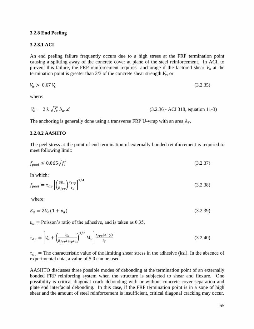
65
3.2.8 End Peeling
3.2.8.1 ACI
An end peeling failure frequently occurs due to a high stress at the FRP termination point
causing a splitting away of the concrete cover at plane of the steel reinforcement. In ACI, to
prevent this failure, the FRP reinforcement requires anchorage if the factored shear Vu at the
termination point is greater than 2/3 of the concrete shear strength , or:
0.67 (3.2.35)
where:
2 λ .d (3.2.36 - ACI 318, equation 11-3)
The anchoring is generally done using a transverse FRP U-wrap with an area .
3.2.8.2 AASHTO
The peel stress at the point of end-termination of externally bonded reinforcement is required to
meet following limit:
(3.2.37)
In which:
(3.2.38)
where:
(3.2.39)
Poisson’s ratio of the adhesive, and is taken as 0.35.
(3.2.40)
The characteristic value of the limiting shear stress in the adhesive (ksi). In the absence of
experimental data, a value of 5.0 can be used.
AASHTO discusses three possible modes of debonding at the termination point of an externally
bonded FRP reinforcing system when the structure is subjected to shear and flexure. One
possibility is critical diagonal crack debonding with or without concrete cover separation and
plate end interfacial debonding. In this case, if the FRP termination point is in a zone of high
shear and the amount of steel reinforcement is insufficient, critical diagonal cracking may occur.

66
In such cases, a critical diagonal shear crack forms and intersects the FRP, then propagates
toward the end of the member. A second possibility occurs in beams with higher amounts of
existing steel shear reinforcement, instead of a single critical diagonal crack, multiple diagonal
cracks of smaller width may occur. In this case, concrete cover separation is generally the
controlling debonding failure mode. Here, failure of the concrete cover is initiated by a crack
near the FRP termination point. The crack then propagates to and then along the level of the steel
tension reinforcement. This mode of failure has been demonstrated experimentally for beams
with externally bonded steel plates and FRP reinforcement, and is the mode of failure discussed
in section 3.2.8.1 above.
A third possibility occurs when high interfacial shear and normal stresses near the end of the
FRP exceed the strength of the weakest element, generally the concrete, and plate-end interfacial
debonding is initiated. Debonding in this case propagates from the FRP termination point toward
the middle of the structural member, near the FRP-concrete interface. Note that this failure mode
is only likely to occur when the FRP is significantly narrower than the beam section. AASHTO
does not quantify a threshold for a ratio at which debonding initiates and propagates.
Although a wide range of predictive models that include numerical, fracture mechanics, data-
fitting, and strength of material-based methods have been developed to address end peeling
failures (Yao, 2004), AASHTO recommends a simplified equation based on the approximate
analysis of Roberts (1989). At present, AASHTO does not specify a standard test method for
determining the peel strength of an FRP reinforcement system from the concrete surface.
However, AASHTO recommends for this purpose the use of ASTM Standard Test Method D
3167, Standard Test Method for Floating Roller Peel Resistance of Adhesives (2010). The
ASTM method can be used for determining the peel resistance of adhesive bonds between rigid
and flexible surfaces adhered together. For cases in which the peeling occurs within the concrete
layer, AASHTO recommends that the peeling strength be limited to and if the peeling
stress exceeds , mechanical anchors at the FRP termination point must be used.
3.2.8.3 TR55
TR55 refers to early research on FRP separation failure and suggests a number of possible
approaches for combating this problem, including: the use of plate end anchorage devices,
flexible adhesives, and imposing limits on the plate aspect (i.e. breadth/thickness) ratio. Bolted
systems, bonded angle sections and composite straps bonded across the soffit plate are examples
of plate end anchorage devices that have been proposed as possible methods of preventing FRP
separation failure. Generally, TR55 states that end plate separation failure can be avoided by
meeting two criteria: 1) limiting the longitudinal shear stress between the FRP and the substrate,
and 2) anchoring the FRP by extending it beyond the point at which it is theoretically no longer
required.
To meet the first criterion, TR55 notes that field experience indicates that limiting the
longitudinal shear stress at the ultimate limit state to a value no greater than 0.8 N/mm2,
premature peeling failure can be avoided. TR55 also presents a procedure to calculate the
minimum anchorage length as it relates to the maximum ultimate bond force. The longitudinal
shear stress, , can be calculated using the following expression ( Eq. 3.2.41):

67
(h-x) / (3.2.41)
The relationship between the bond force, , and the corresponding anchorage length, is
presented in Figure 3.2.13. It is further recommended that a minimum anchorage length of 500
mm should be provided. In situations where it is not possible to provide the maximum allowable
anchorage length, the bond force should be less than the following:
(3.2.42)
Additionally, TR55 considers using an anchorage device, provided its capacity has been verified
by testing.
Figure 3.2.13 – Characteristic bond failure force vs. anchorage length (TR55)
3.2.8.4 JSCE
JSCE does not clearly specify design equations other than the following limiting peeling stress
expression:
(3.2.43)
JSCE notes how the interfacial fracture energy factor varies with the strengthening system,
the number of plies, and the anchoring system used, and states that this value should be
determined through testing. When testing cannot be performed, JSCE recommends using a
value of 4 lb/in (0.7 N/mm).
3.2.8.5 CNR
The following equation is used to limit the peeling stress in CNR:
(3.2.44)
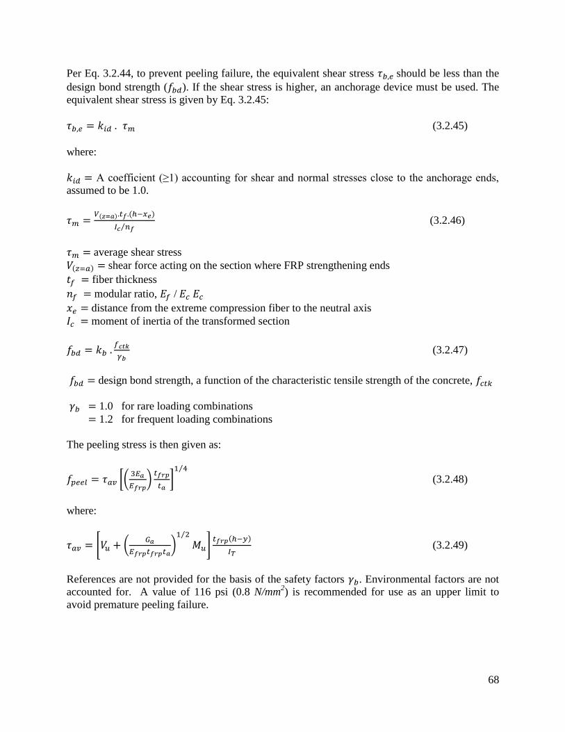
68
Per Eq. 3.2.44, to prevent peeling failure, the equivalent shear stress should be less than the
design bond strength ( ). If the shear stress is higher, an anchorage device must be used. The
equivalent shear stress is given by Eq. 3.2.45:
(3.2.45)
where:
A coefficient (≥1) accounting for shear and normal stresses close to the anchorage ends,
assumed to be 1.0.
(3.2.46)
average shear stress
shear force acting on the section where FRP strengthening ends
fiber thickness
modular ratio, /
distance from the extreme compression fiber to the neutral axis
moment of inertia of the transformed section
(3.2.47)
design bond strength, a function of the characteristic tensile strength of the concrete,
1.0 for rare loading combinations
1.2 for frequent loading combinations
The peeling stress is then given as:
(3.2.48)
where:
(3.2.49)
References are not provided for the basis of the safety factors . Environmental factors are not
accounted for. A value of 116 psi (0.8 N/mm2) is recommended for use as an upper limit to
avoid premature peeling failure.

69
3.2.8.6 Anchorage methods for FRP
For cases of high peeling or shear stress, an anchorage system may be required to avoid
debonding failure. In these cases, an anchorage system might allow the use of a FRP
strengthening plan that otherwise would not meet design code provisions. For example,
anchorage may allow greater strengthening or the use of a wider range of possible FRP
geometries and material properties. A drawback of the use of many anchorage systems is the
added cost and complexity of installation.
NCHRP 678 (Belarbi et al. 2011) describes several anchorage systems, including the near-
surface mounted system (NSM), where the end of the FRP wrap or pre-formed plate is bent and
embedded into a groove cut into the concrete, then secured with epoxy. Another system
available involves anchoring the FRP to the concrete with a spike made from a bundle of fibers.
In this process, half of the spike length is covered with resin and allowed to harden. The pre-
cured spike end is then inserted into a resin-filled hole that is drilled into the concrete, and the
dry fibers on the other end of the spike are spread apart on the surface of the FRP layer to be
anchored, and then saturated with resin. Yet other types of anchorage systems involve
embedding nails or rods into the concrete to secure steel plates on top of the FRP layer to be
anchored.
ISIS also describes several common anchorage systems, including bonding an additional FRP
strip along the edges of the applied FRP; anchoring FRP shear stirrups into the bottom of the slab
in T-beam applications; and clamping the FRP strips with plates and bolts, as later illustrated in
section 3.3.2.3.
3.2.8.7 Summary
A summary of peeling limits and procedures are given in Table 3.2.20.
Table 3.2.20- Peeling summary
Code Quantity Formula Limit
ACI 440.2R
AASHTO
CNR-DT 200 Bond shear
strength
TR55 Shear stress
JSCE Shear stress

70
As shown in the table, different methods are used to evaluate peeling for the various codes. ACI
uses a peeling limit evaluating the shear capacity of concrete at the FRP termination point,
expressed as a function of and section shear capacity and demand ( ). AASHTO
and CNR limits are similar, and are a function of and respectively, while JSCE expresses
the limit in terms of FRP related quantities. To compare code expressions, a
rectangular concrete beam of h=30 in and b= 18 in is considered as an example. The beam is
assumed to have the following properties: factored shear force at the reinforcement end
termination = 100 kips; factored moment at the reinforcement termination = 500 kip-in; materials
properties of Mbrace Saturant and Mbrace CF130 wrap are used, such that fiber thickness (one
ply) = 0.0065 inch; fiber modulus of elasticity = 33000 ksi; adhesive thickness = 0.0022 inch;
adhesive modulus of elasticity = 440 ksi; Poisson ratio of adhesive = 0.40; (assumes a
frequent load combination (for CNR)). Peeling stresses and limits are evaluated as a function of
the amount of FRP strengthening (Figure 3.2.14), and concrete compressive strength (Figure
3.2.15).
Figure 3.2.14 – Peeling stress vs. FRP strengthening area
Figure 3.2.15 – Peeling Stress vs f'c
0.00
0.05
0.10
0.15
0.20
0.25
0.30
0.35
0.40
0 . 1 1 0 . 2 2 0 . 3 3 0 . 4 4 0 . 5 5
CNR AASHTO AASHTO LIMIT STATE CNR LIMIT
Strengthening Area, in2
Pe
elin
g St
ress
, ksi
0.00
0.05
0.10
0.15
0.20
0.25
0.30
0.35
0.40
3 . 0 4 . 0 5 . 0 5 . 5 6 . 0 7 . 0 8 . 0
CNR AASHTO AASHTO Limit CNR LIMIT
Pe
elin
g St
ress
, ksi
Compressive Strength fc', ksi

71
Two notable observations are that; 1) for the example beam, the peeling stress exceeds the
peeling limit in all cases, and end anchorage is required; and 2) peeling stresses significantly
increase as increases, and marginally increases as the amount of FRP strengthening increases.
However, peeling limits are independent of the amount of FRP strengthening, but vary with the
increase in . AASHTO and CNR are similar in the treatment of peeling stresses and peeling
limits, although AASHTO peeling limits are slightly more conservative than those of CNR.
3.2.9 Development Length
3.2.9.1 AASHTO
In AASHTO, the tension development length, , is taken as:
(3.2.50)
where:
= tensile force in the FRP reinforcement corresponding to an FRP strain of 0.005
interface shear transfer = 0.065
The specified development length is required to allow the full tension strength of the FRP to be
developed in the region of maximum moment.
As will be shown below, the AASHTO development length calculations produce more
conservative values as FRP area increases. It was also found that AASHTO development length
values are most conservative at lower values of , producing values as well as trends that are
significantly different from the other codes studied (see Figures 3.2.16 and 3.2.17). Other code
results appear to be independent of the changes in FRP area as well as (ISIS and TR55) or
slightly dependent on these factors (ACI and CNR). To understand the reasons for these
discrepancies, the basis of AASHTO’s development length methodology is reviewed.
The interface shear transfer strength (τint) given in AASHTO is based on the recommendation of
Naaman and Lopez (1999) and Naaman et al. (1999), who conducted tests on uncracked and
precracked reinforced concrete beams externally bonded with FRP reinforcement and subjected
to accelerated freeze-thaw cycles. This shear limit represents a lower bound of the experimental
data found from short-term direct tension tests of FRP reinforcement bonded to concrete surfaces
(Haynes, 1997; Binzindavji and Neale, 1999). This research was conducted for MDOT and is
detailed in Report RC-1372, “Repair and strengthening of reinforced concrete beams using
CFRP Laminates, Behavior of beams subjected to freeze-thaw cycles”.
In the experimental program, reinforced concrete beams were subjected to a maximum of 300
freeze-thaw cycles according to ASTM C666. The parameters investigated were two different
adhesive systems, the Tonen CFRP sheet system (MBrace), and the Sika CFRP system
(Carbodur); as well as the degree of cracking prior to strengthening. It was found that freeze-
thaw cycles influenced the behavior of reinforced concrete beams with glued-on Carbon Fiber

72
Reinforced Plastic (CFRP) laminates, and the recommended value of interface shear transfer
strength (τint) represents the lower bound of the test results.
3.2.9.2 ACI
In ACI, the bond capacity of FRP is developed over a critical length . To develop the effective
FRP stress at a given section, the available anchorage length of FRP should exceed the value
given in the equation below:
in-lb units (3.2.50)
SI units (3.2.50 )
3.2.9.3 ISIS
ISIS specifies the minimum required anchorage length for the externally-bonded FRP beyond the
point where no strengthening is required, . According to the S6-06 bridge code, may be
evaluated as follows:
(3.2.51 - ISIS Eq. 5.29)
Anchorage lengths longer than must be provided if required by the manufacturer's installation
procedure. For cases where is not provided, suitable anchorage mechanisms must be used.
3.2.9.4 – CNR
The optimal bonded length may be estimated as follows:
(3.2.52 - CNR Eq. 4.1)
where:
is in mm; the value from Eq. 3.2.53 should be multiplied by 0.03937 to obtain in inches.
3.2.9.5 TR55
TR55 specifies a threshold anchorage length, , above which no increase in the bond failure
force is possible. The maximum anchorage length, , needed to activate this bond force
iscalculated using the following expressions:
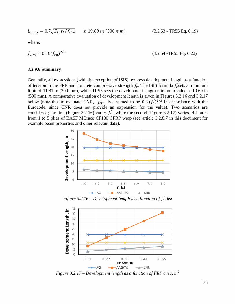
73
(3.2.53 - TR55 Eq. 6.19)
where:
(3.2.54 -TR55 Eq. 6.22)
3.2.9.6 Summary
Generally, all expressions (with the exception of ISIS), express development length as a function
of tension in the FRP and concrete compressive strength . The ISIS formula
sets a minimum
limit of 11.81 in (300 mm), while TR55 sets the development length minimum value at 19.69 in
(500 mm). A comparative evaluation of development length is given in Figures 3.2.16 and 3.2.17
below (note that to evaluate CNR, is assumed to be in accordance with the
Eurocode, since CNR does not provide an expression for the value). Two scenarios are
considered; the first (Figure 3.2.16) varies , while the second (Figure 3.2.17) varies FRP area
from 1 to 5 plies of BASF MBrace CF130 CFRP wrap (see article 3.2.8.7 in this document for
example beam properties and other relevant data).
Figure 3.2.16 – Development length as a function of
, ksi
Figure 3.2.17 – Development length as a function of FRP area, in
2
0
5
10
15
20
25
30
3 . 0 4 . 0 5 . 0 5 . 5 6 . 0 7 . 0 8 . 0
ACI AASHTO CNR
Dev
elo
pm
ent
Len
gth
, in
0
5
10
15
20
25
30
35
40
45
0 . 1 1 0 . 2 2 0 . 3 3 0 . 4 4 0 . 5 5
ACI AASHTO CNR
Dev
elo
pm
ent
Len
gth
, in

74
It can be seen from the Figures that a significant variation in development length requirements
exist. For ISIS and TR55, the lower limits specified generally controlled. For AASHTO,
development length is independent of FRP modulus, while all other codes have expressions for
development length as a function of FRP modulus. The AASHTO expression is also
significantly more sensitive to FRP area. As discussed above, AASHTO recommendations differ
significantly from the other codes and generally provide conservative results. However, the
values considered by AASHTO were specifically based on testing conducted for MDOT at the
University of Michigan that included freeze-thaw conditioning relevant to Michigan.
3.2.10 Flexural Design Approach and Assumptions
3.2.10.1 AASHTO
In AASHTO, the calculation of the flexural strength of reinforced concrete members externally
reinforced with FRP materials assumes perfect bond between the reinforcing steel, FRP
reinforcement and the concrete; that the contribution of tension stress in the concrete to flexural
strength is neglected; the stress-strain behavior for FRP reinforcement is linear-elastic until
failure; the stress-strain behavior of steel reinforcement is bilinear, with elastic behavior up to
yielding and perfectly plastic behavior thereafter; the maximum usable compression strain in the
concrete is equal to 0.003; and the maximum usable strain at the FRP/concrete interface is 0.005.
When concrete compressive strain is less than 0.003, the concrete compression stress distribution
is to be modeled with a parabolic shape according to the following equation:
(3.2.56)
where:
(3.2.57)
is the concrete strain corresponding to the maximum stress on the concrete stress-strain curve.
The factored resistance, , of a steel reinforced concrete rectangular section strengthened with
FRP externally bonded to the beam tension surface is be taken as:
(3.2.58)
where:
= resistance factor = 0.85
(3.2.59)
number of FRP reinforcement plates
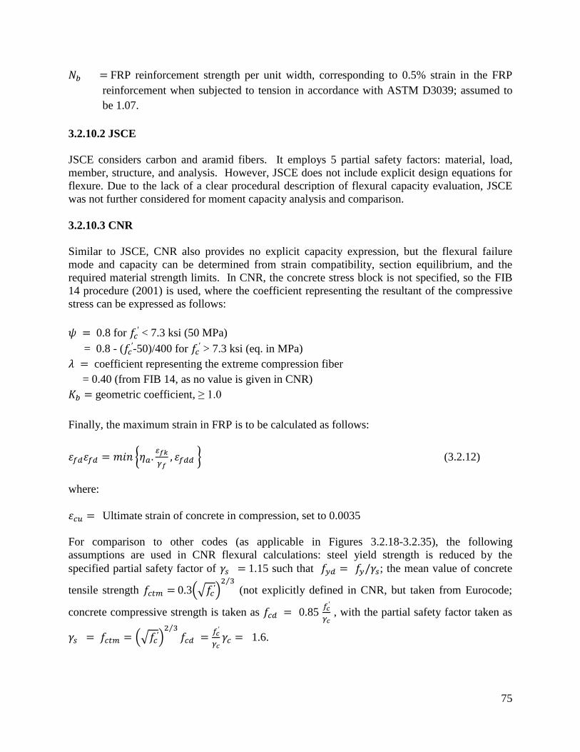
75
FRP reinforcement strength per unit width, corresponding to 0.5% strain in the FRP
reinforcement when subjected to tension in accordance with ASTM D3039; assumed to
be 1.07.
3.2.10.2 JSCE
JSCE considers carbon and aramid fibers. It employs 5 partial safety factors: material, load,
member, structure, and analysis. However, JSCE does not include explicit design equations for
flexure. Due to the lack of a clear procedural description of flexural capacity evaluation, JSCE
was not further considered for moment capacity analysis and comparison.
3.2.10.3 CNR
Similar to JSCE, CNR also provides no explicit capacity expression, but the flexural failure
mode and capacity can be determined from strain compatibility, section equilibrium, and the
required material strength limits. In CNR, the concrete stress block is not specified, so the FIB
14 procedure (2001) is used, where the coefficient representing the resultant of the compressive
stress can be expressed as follows:
0.8 for < 7.3 ksi (50 MPa)
= 0.8 - ( -50)/400 for
> 7.3 ksi (eq. in MPa)
coefficient representing the extreme compression fiber
= 0.40 (from FIB 14, as no value is given in CNR)
geometric coefficient, ≥ 1.0
Finally, the maximum strain in FRP is to be calculated as follows:
(3.2.12)
where:
Ultimate strain of concrete in compression, set to 0.0035
For comparison to other codes (as applicable in Figures 3.2.18-3.2.35), the following
assumptions are used in CNR flexural calculations: steel yield strength is reduced by the
specified partial safety factor of 1.15 such that ; the mean value of concrete
tensile strength 0.3
(not explicitly defined in CNR, but taken from Eurocode;
concrete compressive strength is taken as 0.85
, with the partial safety factor taken as
1.6.

76
3.2.10.4 ACI
ACI assumes that the maximum concrete compressive strain is 0.003. The FRP strain limit is
imposed using equation 3.2.8 as shown below:
(3.2.8 – ACI Eq. 10-2)
(3.2.8 m)
Equation 3.2.60 (ACI Eq. 10-13) is typically used to evaluate the nominal moment capacity of
the section:
(3.2.60 - ACI Eq. 10-13)
For the special case when is smaller than 0.003, values for and are evaluated as follows:
(3.2.61)
(3.2.62)
Using and , the neutral axis location can be evaluated from equation 3.2.63.
(3.2.63)
Steel and FRP service stresses are calculated using equations 3.2.19 and 3.2.20 to ensure
compliance with serviceability requirements.
(3.2.19 - ACI Eq. 10-14)
(3.2.20 - ACI Eq. 10-15)
An environmental reduction factor CE (taken as 0.85 assuming exterior exposure) and the
additional reduction factor specific to FRP are considered in the factored moment calculations.
3.2.10.5 ISIS
The ISIS design procedure is straightforward with the assumptions given in the code. The
neutral axis is determined using strain compatibility and section balance. In ISIS, it is assumed

77
that concrete maximum compressive strain is ≤ 0.0035; the maximum FRP strain (per the bridge
code) = 0.006; and, the appropriate reduction factors are used as specified earlier in this
document.
3.2.10.6 TR55
TR55 is similar to the other codes in its assumptions of the applicability of basic engineering
mechanics to establish section capacity. Specific to TR55 are the following recommendations
for flexural capacity: the FRP strain limit to prevent debonding is taken as 0.008 for uniformly
distributed loads and 0.006 for load effects of simultaneous high shear and moment; and the
ultimate compressive strain in concrete 0.0035.
Unique to TR55 is that the neutral axis location ( ) is calculated from the original section
equilibrium and is not adjusted with the addition of FRP. An additional moment capacity, ,
representing the FRP contribution, is added to the original section nominal moment capacity.
Assuming a flexural section is to be strengthened to carry a larger moment M than its current
capacity, with a singly-reinforced section, the nominal moment is evaluated as follows:
Mr = Fsz + Ff [z + (h - d)] (3.2.64 – UK Eq. 6.14)
where:
Mr = M and Fs = (fy /ɣ ms) . As
3.2.10.7 Summary
For comparison of different code results, a rectangular reinforced concrete beam with b = 18 in
and h = 30 in is considered for strengthening with MBrace CF 130 CFRP. Figures 3.2.18 to
3.2.26 illustrate how moment capacity changes as a function of FRP area and initial steel
reinforcement ratio. It was found that, as expected, an increase in moment capacity accompanies
an increase in FRP area. An exception is observed for ACI with a steel ratio of 0.0171 (Figure
3.2.25 - factored moment case). This exception occurs because the steel reinforcement strain
falls in the transition zone between a tension and compression controlled failure, causing a
reduction in the value of and thus reducing the factored moment as FRP area increases. It was
also found that as steel reinforcing ratio increases, a compression failure is observed in some
codes but not in others. For example, AASHTO and CNR develop compression failures at a
steel reinforcement ratio of 0.0171 for all values of FRP strengthening. It is important to note
that the compression failures were obtained for the relatively low f’c chosen for the evaluation
beam of 3000 psi. This low value was specifically chosen such that the behavior of different
code procedures considering different beam failure modes (i.e. tension and compression
controlled) could be compared. In most cases, where f’c is greater that 3000 psi, the likelihood of
developing a compression failure is reduced for the same amount of FRP reinforcement.
It was also found that due to the need to maintain section equilibrium, when FRP area increases,
FRP strain is reduced. However, when the code-specified FRP strain limits are imposed (for
example, ISIS enforces a maximum FRP strain of 0.006), FRP rupture sometimes becomes the
78
only possible mode of failure. Moreover, ACI exhibits a higher FRP strain at lower values for
FRP area, relative to other codes. This can be attributed to one of the two ACI strain limit
expressions, where the strain limit is inversely propotional to FRP area (Equation 3.2.8).
(3.2.8 – ACI Eq. 10-2)
(3.2.8 m)
Although predicted FRP strains differ, AASHTO and ISIS, both bridge-specific codes, generally
produce similar moment capacity values for the different cases investigated. ACI, AASHTO, and
ISIS are also reasonably consistent with flexural capacity prediction. ACI has greatest capacity
for lower FRP area and higher f’c, while AASHTO and ISIS have greatest capacity for higher
FRP areas. TR55 is more sensitive when there is a change in concrete compressive strength and
is less affected by change in FRP area. It is the most conservative for almost all cases. Despite it
largest FRP strain limit of 0.008, it produces the least capacity due to its conservative (non-
adjustment of the neutral axis) flexural capacity calculation method. In most cases, FRP rupture
was found to be the mode of failure.
Figures 3.2.27-3.2.35 illustrate the effect of changing f’c on moment capacity, as a function of
several other parameters. For this comparison, FRP area was fixed at 3 plies of 17 in wide of
MBrace CF130 CFRP. As expected, higher FRP strains result in higher the moment capacities.
It was also found that ACI results in higher values for FRP strain as well as factored and
unfactored moments when compared to other codes. For lower steel reinforcement ratios ( =
0.0033 and 0.0064), tension failure is the dominant mode of failure, though the higher value for
when combined with the FRP, results in possible compression failures (for example,
AASHTO and CNR transition from tension failure into compression failure at the 0.0171 steel
reinforcement ratio).
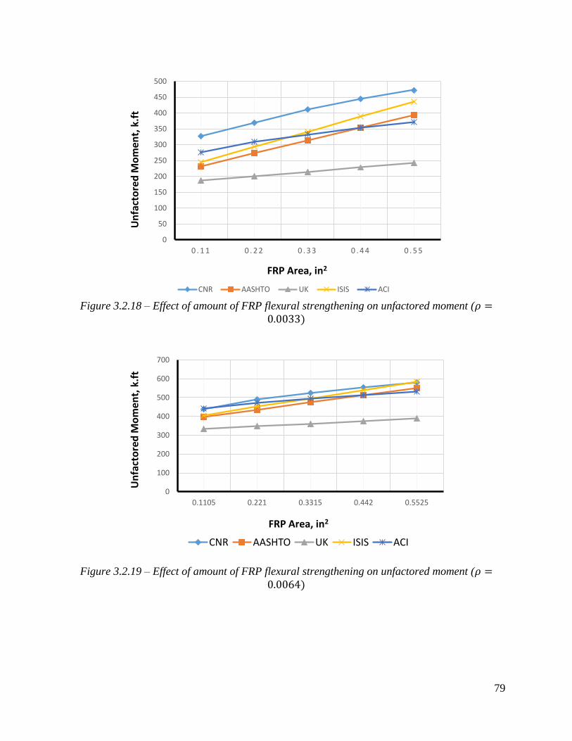
79
Figure 3.2.18 – Effect of amount of FRP flexural strengthening on unfactored moment (
Figure 3.2.19 – Effect of amount of FRP flexural strengthening on unfactored moment (
0
50
100
150
200
250
300
350
400
450
500
0 . 1 1 0 . 2 2 0 . 3 3 0 . 4 4 0 . 5 5
CNR AASHTO UK ISIS ACI
FRP Area, in2
Un
fact
ore
d M
om
ent,
k.f
t
0
100
200
300
400
500
600
700
0.1105 0.221 0.3315 0.442 0.5525
CNR AASHTO UK ISIS ACI
FRP Area, in2
Un
fact
ore
d M
om
ent,
k.f
t

80
Figure 3.2.20 – Effect of amount of FRP flexural strengthening on unfactored moment (
Figure 3.2.21 – Effect of amount of FRP flexural strengthening on factored moment (
0
200
400
600
800
1000
1200
0 . 1 1 0 . 2 2 0 . 3 3 0 . 4 4 0 . 5 5
CNR AASHTO UK ISIS ACI
0
50
100
150
200
250
300
350
400
0 . 1 1 0 . 2 2 0 . 3 3 0 . 4 4 0 . 5 5
AASHTO UK ISIS ACI

81
Figure 3.2.22 – Effect of amount of FRP flexural strengthening on FRP strain (
Figure 3.2.23 – Effect of amount of FRP flexural strengthening on factored moment (
0.000
0.002
0.004
0.006
0.008
0.010
0.012
0.014
0 . 1 1 0 . 2 2 0 . 3 3 0 . 4 4 0 . 5 5
CNR AASHTO ISIS ACI
0
100
200
300
400
500
600
700
0 . 1 1 0 . 2 2 0 . 3 3 0 . 4 4 0 . 5 5
CNR AASHTO UK ISIS ACI

82
Figure 3.2.24 – Effect of amount of FRP flexural strengthening on FRP strain (
Note: As steel reinforcement ratio increases and FRP strain decreases, failure mode changes
from compression to tension failure. Also, with increasing f’c, the mode of failure changes from
compression to tension failure.
Figure 3.2.25 – Effect of amount of FRP flexural strengthening on factored moment (
0.000
0.002
0.004
0.006
0.008
0.010
0.012
0 . 1 1 0 . 2 2 0 . 3 3 0 . 4 4 0 . 5 5
CNR AASHTO ISIS ACI
0
100
200
300
400
500
600
700
800
900
0 . 1 1 0 5 0 . 2 2 1 0 . 3 3 1 5 0 . 4 4 2 0 . 5 5 2 5
CNR AASHTO UK ISIS ACI

83
Figure 3.2.26 – Effect of amount of FRP flexural strengthening on FRP strain (
Figure 3.2.27 – Effect of
on unfactored moment (
0
0.001
0.002
0.003
0.004
0.005
0.006
0.007
0 . 1 1 0 . 2 2 0 . 3 3 0 . 4 4 0 . 5 5
CNR AASHTO ISIS ACI
0
100
200
300
400
500
600
700
3 . 0 4 . 0 5 . 0 5 . 5 6 . 0 7 . 0 8 . 0
CNR AASHTO UK ISIS ACI

84
Figure 3.2.28 – Effect of
on unfactored moment (
Figure 3.2.29 – Effect of
on unfactored moment (
0
100
200
300
400
500
600
700
800
3 . 0 4 . 0 5 . 0 5 . 5 6 . 0 7 . 0 8 . 0
CNR AASHTO UK ISIS ACI
0
200
400
600
800
1000
1200
1400
3 . 0 4 . 0 5 . 0 5 . 5 6 . 0 7 . 0 8 . 0
CNR AASHTO UK ISIS ACI

85
Figure 3.2.30 – Effect of
on factored moment (
Figure 3.2.31 – Effect of on factored moment (
0
100
200
300
400
500
600
700
3 . 0 4 . 0 5 . 0 5 . 5 6 . 0 7 . 0 8 . 0
CNR AASHTO UK ISIS ACI
0
100
200
300
400
500
600
700
800
3 . 0 4 . 0 5 . 0 5 . 5 6 . 0 7 . 0 8 . 0
CNR AASHTO UK ISIS ACI

86
Figure 3.2.32 – Effect of on factored moment (
Figure 3.2.33 – Effect of
on FRP strain (
0
200
400
600
800
1000
1200
1400
3 . 0 4 . 0 5 . 0 5 . 5 6 . 0 7 . 0 8 . 0
CNR AASHTO UK ISIS ACI
0.000
0.002
0.004
0.006
0.008
0.010
0.012
0.014
3 . 0 4 . 0 5 . 0 5 . 5 6 . 0 7 . 0 8 . 0
CNR AASHTO ISIS ACI

87
Figure 3.2.34 – Effect of
on FRP strain (
Figure 3.2.35 – Effect of
on FRP strain (
0.000
0.001
0.002
0.003
0.004
0.005
0.006
0.007
0.008
0.009
0.010
3 . 0 4 . 0 5 . 0 5 . 5 6 . 0 7 . 0 8 . 0
CNR AASHTO ISIS ACI
changing from compression to tension failure mode

88
3.3 Shear FRP Strengthening of RC/PC Bridge Members
3.3.1 Introduction
A review and analysis of the shear strengthening provisions for concrete bridge members with
FRP is presented in this section for the six reviewed guidelines. The organization of this section
is based on the framework presented in ACI 440.2R-08 since it offers the most complete
coverage of the subject. The specific items for analysis and comparison include:
Wrapping schemes
Strength reduction factors
Reinforcement and spacing limits
FRP strain limits
Shear design approach and assumptions
Shear analysis procedure and results
3.3.2 Wrapping schemes
Three types of wrapping schemes are generally used to increase the shear strength of rectangular
beams: 4-sided (complete or "closed") wrap, 3-sided (U-wrap), and 2-sided wrap, as shown in
Figure 3.3.2. Each standard mentions these three types, and some offer recommendations and
comments, which are summarized below.
3.3.2.1 ACI
ACI notes that the completely-wrapped scheme is the most efficient, followed by the three-sided
U-wrap, although complete wrap is more common in columns. In all wrapping schemes, the
FRP system can be installed continuously along the span of a member or placed as discrete
strips. However, the use of continuous FRP that completely encases a member is discouraged
since it potentially prevents migration of trapped moisture.
3.3.2.2 AASHTO
Similar to ACI, AASHTO notes that the 2-sided wrap is least effective, as it is subject to
premature debonding under high shear loads. Similarly, U-wrap schemes may debond prior to a
complete wrap scheme, but U-wrap is popular in practice because of its wide applicability and
ease of installation. U-wrap, or U-jacketing, can be combined with anchorage to increase the
effectiveness of the FRP by anchoring the fibers, preferably, in the compression zone. Properly
design anchors can result in the fibers reaching their tensile capacity prior to debonding,
permitting the jacket to behave as if it were completely wrapped.
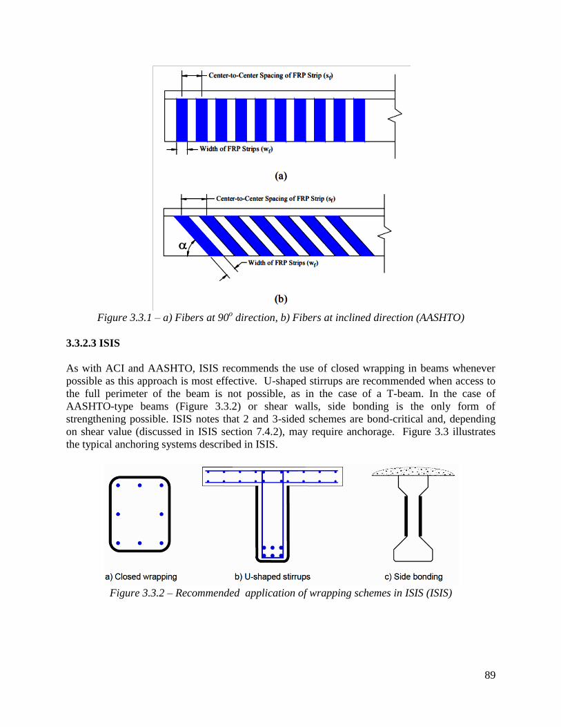
89
Figure 3.3.1 – a) Fibers at 90
o direction, b) Fibers at inclined direction (AASHTO)
3.3.2.3 ISIS
As with ACI and AASHTO, ISIS recommends the use of closed wrapping in beams whenever
possible as this approach is most effective. U-shaped stirrups are recommended when access to
the full perimeter of the beam is not possible, as in the case of a T-beam. In the case of
AASHTO-type beams (Figure 3.3.2) or shear walls, side bonding is the only form of
strengthening possible. ISIS notes that 2 and 3-sided schemes are bond-critical and, depending
on shear value (discussed in ISIS section 7.4.2), may require anchorage. Figure 3.3 illustrates
the typical anchoring systems described in ISIS.
Figure 3.3.2 – Recommended application of wrapping schemes in ISIS (ISIS)
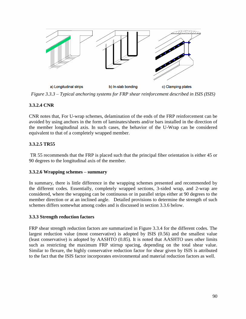
90
Figure 3.3.3 – Typical anchoring systems for FRP shear reinforcement described in ISIS (ISIS)
3.3.2.4 CNR
CNR notes that, For U-wrap schemes, delamination of the ends of the FRP reinforcement can be
avoided by using anchors in the form of laminates/sheets and/or bars installed in the direction of
the member longitudinal axis. In such cases, the behavior of the U-Wrap can be considered
equivalent to that of a completely wrapped member.
3.3.2.5 TR55
TR 55 recommends that the FRP is placed such that the principal fiber orientation is either 45 or
90 degrees to the longitudinal axis of the member.
3.3.2.6 Wrapping schemes – summary
In summary, there is little difference in the wrapping schemes presented and recommended by
the different codes. Essentially, completely wrapped sections, 3-sided wrap, and 2-wrap are
considered, where the wrapping can be continuous or in parallel strips either at 90 degrees to the
member direction or at an inclined angle. Detailed provisions to determine the strength of such
schemes differs somewhat among codes and is discussed in section 3.3.6 below.
3.3.3 Strength reduction factors
FRP shear strength reduction factors are summarized in Figure 3.3.4 for the different codes. The
largest reduction value (most conservative) is adopted by ISIS (0.56) and the smallest value
(least conservative) is adopted by AASHTO (0.85). It is noted that AASHTO uses other limits
such as restricting the maximum FRP stirrup spacing, depending on the total shear value.
Similar to flexure, the highly conservative reduction factor for shear given by ISIS is attributed
to the fact that the ISIS factor incorporates environmental and material reduction factors as well.

91
Figure 3.3.4 - FRP strength reduction factor
3.3.4 Reinforcement limits and spacing limits
3.3.4.1 ACI
3.3.4.1.1 Shear strengthening limits
The sum of the shear strengths provided by the FRP and existing shear reinforcement are to be
limited to the criteria given for steel alone, as given in ACI 318. This limit is given in terms of
four times the nominal shear strength of the concrete ( ), and is expressed as:
in-lb units (3.3.1a – ACI eq.11-11)
SI units (3.3.1b)
3.3.4.1.2 Spacing of FRP strips
For external FRP shear strengthening in the form of discrete strips, ACI specifies limits in
articles 11.1 and 11.4.2. Article 11.1 stipulates that the center-to-center spacing between the
strips should not exceed the sum of d/4 plus the width of the strip. Moreover, Article 11.4.2
states that spacing limits should follow those given in ACI 318, which are as follows (equations
3.3.2a and 3.3.2b):
≤
(3.3.2a)
(3.3.2b)
0.83 0.85
0.70 0.65
0.56
0.80
0.0
0.1
0.2
0.3
0.4
0.5
0.6
0.7
0.8
0.9
1.0
CNR AASHTO ACI UK ISIS JSCE
AASHTO ACI UK ISIS JSCE CNR
Stre
ngt
h R
edu
ctio
n F
acto
r

92
3.3.4.2 AASHTO
3.3.4.2.1 Maximum FRP shear reinforcement
In AASHTO, the amount of FRP used cannot result in a section with nominal shear strength
exceeding the limit given in equation 3.3.3:
(3.3.3-AASHTO eq. 5.8.3.3-2)
where:
(3.3.4)
The factored shear strength, , is defined as:
(3.3.5 – AASHTO eq. 4.3.1-1)
where:
cV = the nominal shear strength provided by the concrete in accordance with Article 5.8.3.3 of
the AASHTO LRFD Bridge Design Specifications
(3.3.6 – AASHTO eq.5.8.3.3-3)
sV = the nominal shear strength provided by the transverse steel reinforcement in accordance
with Article 5.8.3.3 of the AASHTO LRFD Bridge Design Specifications
(3.3.7 - LRFD Eq.5.8.3.3-4)
where:
(3.3.8)
, ,
pV = component of the effective prestressing force in the direction of applied shear as specified
in Article 5.8.3.3 of the AASHTO LRFD Bridge Design Specifications
frpV = the nominal shear strength provided by the externally bonded FRP system in accordance
with AASHTO Article 4.3
= 0.9
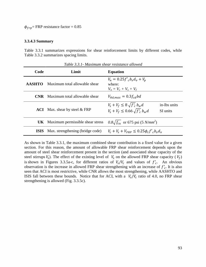
93
= FRP resistance factor = 0.85
3.3.4.3 Summary
Table 3.3.1 summarizes expressions for shear reinforcement limits by different codes, while
Table 3.3.2 summarizes spacing limits.
Table 3.3.1- Maximum shear resistance allowed
Code Limit Equation
AASHTO Maximum total allowable shear
where:
Vn = Vc + Vs + Vf
CNR Maximum total allowable shear
ACI Max. shear by steel & FRP
in-lbs units
SI units
UK Maximum permissible shear stress 0.8 or 675 psi (5 N/mm2)
ISIS Max. strengthening (bridge code)
As shown in Table 3.3.1, the maximum combined shear contribution is a fixed value for a given
section. For this reason, the amount of allowable FRP shear reinforcement depends upon the
amount of steel shear reinforcement present in the section (and associated shear capacity of the
steel stirrups ). The effect of the existing level of on the allowed FRP shear capacity ( )
is shown in Figures 3.3.5a-c, for different ratios of and values of . An obvious
observation is the increase in allowed FRP shear strengthening with an increase of It is also
seen that ACI is most restrictive, while CNR allows the most strengthening, while AASHTO and
ISIS fall between these bounds. Notice that for ACI, with a ratio of 4.0, no FRP shear
strengthening is allowed (Fig. 3.3.5c).

94
Figure 3.3.5a
Figure 3.3.5b
Figure 3.3.5c
Figure 3.3.5 – Effect of on allowed
0
200
400
600
800
1000
1200
4000 6000 8000
Vf a
llo
we
d, k
ips
f'c (psi)
Vs/Vc = 1.0
AASHTO/ISIS
CNR
ACI
0
200
400
600
800
1000
1200
4000 6000 8000
Vf a
llo
we
d, k
ips
f'c (psi)
Vs/Vc = 2.5
AASHTO/ISIS
CNR
ACI
0
200
400
600
800
1000
1200
4000 6000 8000
Vf a
llo
we
d, k
ips
f'c (psi)
Vs/Vc = 4.0
AASHTO/ISIS
CNR
ACI

95
Table 3.3.2 - Maximum spacing of FRP shear reinforcement
Code Equation
AASHTO
CNR 2 in (50 mm) ≤ ≤ 10 in (250 mm), and
≤ ≤ min {0.5d, 3 , + 8 in (200) mm}.
ACI
≤
ISIS
Bridge Code S6-06:
The effect of the FRP strip width on spacing limits for different codes is evaluated for different
beam depth using beam dimensions provided in section 3.3.6.7 of this report. Beam depths
considered are 12, 24, 36, 48, and 60 in. Figures 3.3.7 to 3.3.11 present the maximum spacing
limits as a function of strip width for different codes. Except for CNR and ISIS, codes have
different maximum spacing limits depending the applied shear value. For most codes, spacing
limits for low shear values fall between 10 - 20 in, while for high shear values, limits fall
between 5-10 in. Limits are generally expressed as a function of concrete compressive strength.
However, the ISIS S6-06 bridge code spacing limit is independent of concrete compressive
strength and is a function of the depth and strip width .
Figure 3.3.6– Effect of strip width on maximum strip spacing, d = 12

96
Figure 3.3.7– Effect of strip width on maximum strip spacing, d = 24
Figure 3.3.8– Effect of strip width on maximum strip spacing, d = 36

97
Figure 3.3.9 – Effect of strip width on maximum strip spacing, d = 48
Figure 3.3.10 – Effect of strip width on maximum strip spacing, d = 60
3.3.5 FRP design strain limits
3.3.5.1 ACI
For completely wrapped members with FRP, ACI sets the following FRP strain limit to prevent
wide cracks from forming that could cause a loss of aggregate interlock in the concrete (equation
3.3.18, ACI equation 11-6a):

98
(3.3.18 – ACI eq. 11-6a)
For U-wrap and 2-sided wrap schemes, aggregate interlock is preceded by FRP delamination.
Therefore, setting strain limits to prevent delamination failure is the control criterion. The
following strain limit equation incorporates a bond-reduction coefficient applicable to shear
(equation 3.3.19, ACI equation 11-6b):
(3.3.19 – ACI eq. 11-6b)
where:
(3.3.20 - ACI eq. 11-7)
(SI units)
(3.3.21 - ACI eq. 11-8)
(SI units)
(in - lb units) (3.3.22 - ACI eq. 11-9)
(SI units)
(3.3.23 - ACI eq. 11-10)
3.3.5.2 AASHTO
AASHTO specifies the effective FRP strain, , which represents the average strain experienced
by the FRP at shear failure of the strengthened member. When the FRP is fully anchored, as in
the case of complete wrap or for U-wrap with anchors, FRP rupture is the expected mode of
failure. The strain limit to prevent such a failure is expressed as follows:
(3.3.24)
where:

99
(3.3.25)
In the case of side bonding or U-wrap with other anchorage causing non-rupture failures to be
the more likely mode of failure, the expression for strain limit is as follows:
(3.3.26)
where:
(3.3.27)
The reduction factor, , is to be found from tests in which the load is applied at a distance from
the support sufficient to assume that plane sections before deformation remain plane after
deformation, i.e. slender beam behavior. Thus, these provisions are only applicable to beams
with a shear span-to-depth ratio greater than 2.5.
3.3.5.3 ISIS
The reviewed ISIS procedure to establish strain limits is taken from the S6-06 bridge code. Strain
limits are specified in Equations 3.3.28a-c (7.3) with limits for FRP strength given by Eq.
3.3.28a (7.3a), aggregate interlock by Eq. 3.3.28b (7.3b), and bond critical applications such as
U-shaped FRP stirrups by Eq. 3.3.28c (7.3c).
FRP Strength (3.3.28a – ISIS eq 7-3a)
Aggregate interlock (3.3.28b – ISIS eq 7-3b)
Bond capacity (U-wrap only) (3.3.28c – ISIS eq 7-3c)
Equation 3.3.28c requires the evaluation of the bond reduction coefficient . The steps for
calculating are identical to those described for ACI, above.
3.3.5.4. Summary
Table 3.3.3 summarizes the shear strengthening strain limits. UK and CNR have fixed strain
limits of 0.004 for U-wrap and side wrap, while CNR has a limit of 0.005 for a completely
wrapped system.

100
Table 3.3.3 - Specified maximum FRP strain for different codes
Code Application Equation
AASHTO
U-Wrap and 2-sided
where:
Completely wrapped
where:
CNR
Completely wrapped
U-wrap and 2-sided 0.004
UK U-Wrap 0.004
ACI
Completely wrapped
U-wrap and 2-sided
ISIS
All wrapping cases
U-shaped FRP stirrups only
3.3.6 Shear design approach and assumptions
3.3.6.1 ACI
The goal of the analytical procedure described in ACI is to evaluate FRP shear resistance
while applying applicable strain limits necessary to meet strength, aggregate interlock and bond
requirements. The following are the steps needed for FRP shear calculation.
Step 1: Evaluate the bond reduction coefficient (provided in the strain limits section above).
(3.3.20 - ACI eq. 11-7)
(SI units)
Step 2: Evaluate for U-wrap case using the strain limit equation:
(3.3.19 – ACI eq. 11-6b)
Step 3: Calculate the effective stress of FRP, :

101
(3.3.29 - ACI eq. 11-5)
Step 4: Calculate FRP shear area,
(3.3.30 - ACI eq. 11-4)
Step 5: Calculate shear resistance for FRP, :
(3.3.31 - ACI eq. 11-3)
For a 90 degree angle (i.e. vertically placed strips), (sin + cos ) = 1, as per the assumption in
eq. 3.3.33.
Step 6: Calculate shear resistance by concrete and steel:
(3.3.32)
(3.3.33)
Step 7: Calculate nominal and factored shear by concrete, steel, and FRP:
3.3.6.2 ISIS
The ISIS procedure to calculate the shear resistance of FRP is as follows:
Step 1: Evaluate
= The greater of 0.72h or 0.9d
Step 2: Choose the smallest FRP strain value from the following conditions (ISIS eq. 7.3):
FRP Strength (3.3.28a – ISIS eq. 7-3a)
Aggregate interlock (3.3.28b – ISIS eq. 7-3b)
Bond capacity (U-wrap only) (3.3.28c – ISIS eq. 7-3c)
Step 3: Use equation 3.32 to evaluate VFRP:

102
(3.3.32 – ISIS eq. 7-3c)
Step 4: Calculate the shear resistance of concrete and steel (building code):
For beams (3.3.33a – ISIS eq. 7-22a)
For columns (3.3.33b – ISIS eq. 7-22b)
For walls (3.3.33c – ISIS eq. 7-22c)
(3.3.34 – ISIS eq. 7.21)
Step 6: Calculate the total shear capacity of the concrete, steel, and FRP:
Note: when computing the unfactored total shear, the reduction factors , , and are
dropped from the equations for , , and .
3.3.6.3 AASHTO
The AASHTO procedure is as follows:
Step 1: Evaluate the nominal shear resistance of the concrete:
Vc = 0.0316 bv dv (3.3.35)
Assuming =2 and = 45o (simplified procedure), dv = Max ( d-
, 0.9d, 0.72 )
Step 2: Evaluate the nominal shear resistance of the steel:
(3.3.36)
where:
S = internal shear reinforcement spacing
Av = area of internal shear reinforcement
Step 3: Evaluate the nominal shear resistance of the FRP:
(3.3.37, AASHTO eq. 4.3.2-1)

103
where:
= reinforcement ratio of FRP
for discrete strips,
(3.3.38a)
for continuous sheets,
(3.3.38b)
= FRP reinforcement thickness
= width of the strip
= center-to-center spacing of FRP
= effective web width taken as the minimum web width within the effective depth (df)
= effective stress of FRP
= effective depth of FRP measured from the top of FRP reinforcement to the centroid of the
longitudinal reinforcement
= angle of inclination of FRP with respect to the longitudinal axis of the member
= modulus of elasticity of FRP
= effective strain of FRP (refer to equations 3.3.24 - 3.3.27)
Step 4: Evaluate the nominal shear resistance of the member:
3.3.6.3.1 AASHTO GFRP
The steps to calculate shear resistance for AASHTO GFRP are as follows:
Step 1: Evaluate the nominal shear resistance provided by the concrete:
Vc = 0.16 bw c 0.32 bo c (3.3.39)
where:
= distance from extreme compression fiber to neutral axis, in
= ratio of depth of neutral axis to reinforcement depth
(3.3.40 – AGFRP eq. 2.7.3-4)
bw = width of web, in
= distance from extreme compression fiber to centroid of tension reinforcement, in
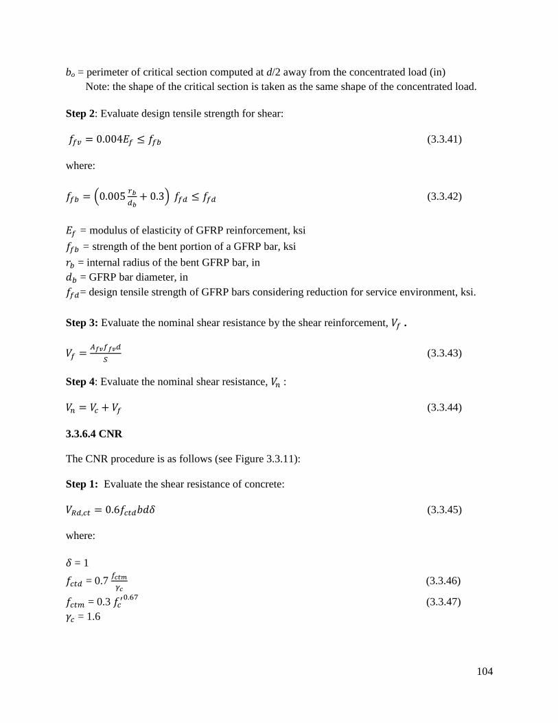
104
bo = perimeter of critical section computed at d/2 away from the concentrated load (in)
Note: the shape of the critical section is taken as the same shape of the concentrated load.
Step 2: Evaluate design tensile strength for shear:
(3.3.41)
where:
(3.3.42)
= modulus of elasticity of GFRP reinforcement, ksi
= strength of the bent portion of a GFRP bar, ksi
= internal radius of the bent GFRP bar, in
= GFRP bar diameter, in
= design tensile strength of GFRP bars considering reduction for service environment, ksi.
Step 3: Evaluate the nominal shear resistance by the shear reinforcement, .
(3.3.43)
Step 4: Evaluate the nominal shear resistance, :
(3.3.44)
3.3.6.4 CNR
The CNR procedure is as follows (see Figure 3.3.11):
Step 1: Evaluate the shear resistance of concrete:
(3.3.45)
where:
= 1
= 0.7
(3.3.46)
= 0.3 (3.3.47)
= 1.6

105
Step 2: Evaluate the shear resistance of steel:
=
. . 0.9 (3.3.48)
where:
, s, and represent area, spacing, and steel stirrups yield strength, respectively.
Step 3: Evaluate the effective FRP design strength:
For a U-wrap configuration:
(3.3.49)
For completely wrapped members having rectangular cross sections:
(3.3.50)
where:
= design strength of FRP reinforcements
, and 0 ≤
≤ 0.5 (3.3.51)
Step 4: Evaluate the FRP contribution to the shear capacity:
For a rectangular cross-section and FRP side bonding configuration:
(3.3.52a)
For U-wrapped or completely wrapped configurations:
(3.3.52b)
Step 5: Evaluate the total shear capacity:
(3.3.53 – CNR eq. 4.24)
where:
(3.3.54 – CNR eq. 10.14)

106
= 1.20
d = member effective depth
hw = stem depth
= effective FRP design strength
= thickness of the adopted FRP system
= FRP width
= FRP spacing
Figure 3.3.11 - CNR shear strengthening notation (CNR)
3.3.6.5 JSCE
The JSCE procedure is as follows:
Step 1: Evaluate the shear resistance of concrete:
(3.3.55 – JSCE eq. 6.4.4)
where:
(3.3.56 – JSCE eq. 6.4.5)
N'd
= design axial compressive force
Md
= design bending moment
M0
= decompression moment
bw
= web width

107
d = effective depth
pw
= As/(b
w x d)
As = cross-sectional area of reinforcing bars in tension side
f'cd
=design compressive strength of concrete (N/mm2
)
γb = member factor (in general, may be set to 1.3)
Step 2: Evaluate the shear resistance of steel:
(3.3.57 – JSCE eq. 6.4.6)
where:
Aw
= total cross-sectional area of shear reinforcement in space ss
fwyd
= design tension yield strength of shear reinforcement [58 ksi max. (400 N/mm2)]
αs = angle formed by shear reinforcement about the member axis
ss = spacing of shear reinforcement
z = lever arm length (generally may be set to d/1.15)
γb
= member factor (generally may be set to 1.15)
Step 3: Evaluate the effective FRP design strength:
(3.3.58 – JSCE eq. 6.4.7)
where:
K = shear reinforcing efficiency of continuous fiber sheets according to Equation 3.59 (JSCE eq.
6.4.8)
(3.3.59 – JSCE eq. 6.4.8)
R=
Step 4: Evaluate the total shear capacity:
(3.3.60 – JSCE eq. 6.4.3)

108
3.3.6.6 UK
The maximum allowable design shear force due to ultimate loads, VR,max at any cross-section, is
obtained from:
(3.3.61 – UK TR55 eq. 7.1)
where:
= width of section
= effective depth of section
Step 1: Evaluate the shear resistance of concrete (per BS 8110):
(3.3.62)
Step 2: Evaluate the shear resistance of steel (BS 8110):
(3.3.63)
Step 3: Evaluate the effective FRP design strength:
The amount of FRP required can be calculated using the same principles as in conventional
reinforced concrete design. The shear resistance of the FRP is given by:
(3.3.64 – UK TR55 eq. 7.3)
where:
= area of FRP shear reinforcement
= 2tf wfe assuming that the FRP is placed on both sides of the member
wfe = effective width of FRP, which is a function of shear crack angle and FRP strengthening
configuration, equal to (df - Le) where FRP is in the form of a U-jacket and (df - 2Le),
where FRP is bonded to side faces
Le = effective bond length= 461.3 / (tf .Efd )0.58
fe = design strain in the FRP
β = angle between FRP and the longitudinal axis of the member = 45° or 90°
df = effective depth of FRP shear reinforcement, usually equal to d for rectangular sections
and (d - slab thickness) for T -sections

109
sf = spacing between the centre line of FRP plates (see Section 3.7.3). Note that for
continuous sheet reinforcement sf = wfe
γmf = partial safety factor for FRP
Step 4: Evaluate the total shear capacity. Add the concrete, steel, and FRP shear components:
3.3.6.7 Summary
To identify the effect of different parameters on the shear capacity of beams according to the
different code procedures, an example singly-reinforced rectangular beam section was examined.
The example beam has a f’c = 4 ksi, and grade 60 longitudinal steel with area = 3 in2, and #3
stirrups spaced at 12 in ( =0.22 in2). The analysis includes the use of a single CFRP ply of
BASF MBrace CF130 to strengthen the beam in shear with a U-wrap scheme. The critical
variables explored include the width of the FRP shear strengthening strip and the spacing
between strips.
All applicable code reduction factors are removed when calculating unfactored FRP shear
results, which are presented in Figures 3.3.12-3.3.15 for FRP stirrups. As shown in the figures,
unfactored shear resistance values are very close for the different codes. As expected, the FRP
shear capacities increase as FRP spacing decreases. Strip width has a minimal impact on
capacity.
When code reduction factors are applied, some significant differences in capacity are observed,
as shown in Figures 3.16-3.19 for FRP strips. Here, AASHTO and ACI consistently provide the
largest design capacity values for FRP. Factored shear values for CNR, UK and ISIS result in
nearly identical values as well, but significantly lower than AASHTO and ACI, with shear
resistance values approximately 30 to 40% higher than those provided by CNR, UK and ISIS.
Note that some code values do not appear on the graphs; this is due to a maximum strip spacing
restriction. This is particularly apparent for ACI, which has relatively strict spacing
requirements.
Figures 3.3.20 and 3.3.21 illustrate the FRP shear resistance for continuous U-wrap. As shown in
Figure 3.3.30, results are similar for all codes. However, large differences emerge when
reduction factors are applied, as shown in Figure 3.3.21. Similar to the FRP strip case,
AASHTO and ACI provide the highest (and similar) design capacities, while the remaining
codes provide similar, lower capacities.
Figures 3.3.22 and 3.3.23 compare 2-sided to U-wrap results. In all cases, 2-sided results
consistently provide less capacity than U-wrap, as expected. Note, however, that AASHTO
limits the maximum strain of FRP to 0.004 for both U-wrap and 2 sided schemes, and provides
the same formula for shear resistance. Moreover, TR-55 does not provide an explicit procedure
to calculate 2-sided shear capacity. JSCE and ISIS do not offer any formula for calculating the
shear resistance of two sided wrap.

110
In Figure 3.3.24, the effect of changing FRP strip width on the components of the total shear
resistance (for a constant gap between strips of d/4, which is the maximum allowed for ACI
code). ACI, AASHTO and ISIS have somewhat similar results, while TR55 and CNR are most
conservative. JSCE does not provide enough information to calculate the shear resistance of
steel or concrete. As shown, increasing the FRP strip width does not result in significant changes
in shear resistance (note that the maximum spacing allowed in CNR is exceeded in the last two
widths shown in the graph, and is therefore not shown). This can be verified with Figure 3.3.25,
which illustrates the relatively change in FRP capacity with strip width, for a constant gap
between strips. Note that a 12 in strip width exceeds the maximum allowed in CNR. It appears
that all codes have similar trends.
Figure 3.3.26 presents the effect of the ratio of the effective depth of FRP shear reinforcement to
the effective depth of the section on unfactored FRP shear resistance. In the figure, the effective
depth of the section is taken as 26 in and the effective depth of FRP is varied from 16 to 24 in.
Note that the CNR approach for calculating shear resistance has no relationship to the effective
depth of FRP, and was thus not included on the graph. As shown, AASHTO and ISIS results are
very close, with increasing ratios of (dfrp/d) resulting in increased capacities. Although TR55
provides significantly lower capacities, trends are similar.
In Figures 3.3.27-3.3.29, the effect of changing the beam height on the components of total
unfactored shear resistance is examined (for the case of continuous U-wrap). In the figures, the
effective depth of the section is assumed to equal 4 in less than the beam height, while the
effective depth of the FRP is assumed to be equal to 0.9 of the effective depth of the section,
while the steel stirrups are assumed to be #3 bars. Changing the height of the beam has the most
effect on the total shear resistance, which is most sensitive to the concrete component of
resistance. ACI provides the highest capacities, although AASHTO and ISIS are similar but
slightly lower.
Figures 3.3.30-3.3.32 show the effect of changing beam height on the shear capacity of each of
the contributing components (concrete, steel, FRP) individually. In general, AASHTO, ACI,
ISIS, and CNR provide similar values for FRP and concrete, while TR55 is significantly more
conservative, especially at larger beam depths. Code results are more similar for steel capacity,
where ISIS and CNR are most conservative.

111
Figure 3.3.12 - Unfactored fiber shear resistance vs FRP spacing, width = 6 in, U-wrap
Figure 3.3.13 - Unfactored fiber shear resistance vs FRP spacing, width = 8 in, U-wrap
0
5
10
15
20
25
30
8 1 0 1 2 Un
fact
ore
d S
hea
r R
esis
tan
ce, k
ips
FRP Spacing, in AASHTO CNR ACI ISIS UK
0
5
10
15
20
25
30
35
1 0 1 2 1 4 Un
fact
ore
d F
iber
Sh
ear
Res
ista
nce
, kip
s
FRP Spacing, in
AASHTO CNR ACI ISIS UK

112
Figure 3.3.14 - Unfactored fiber shear resistance vs FRP spacing, width = 10 in, U-wrap
Figure 3.3.15 - Unfactored fiber shear resistance vs FRP spacing, width = 12 in, U-wrap
Note that a 12 in FRP width exceeds the maximum allowed in CNR (10 in), and CNR results thus do not appear.
0
5
10
15
20
25
30
35
1 2 1 4 1 6
Un
fact
ore
d F
iber
Sh
ear
Res
ista
nce
, kip
s
FRP Spacing, in
AASHTO CNR ACI ISIS UK
0
5
10
15
20
25
30
35
1 4 1 6 1 8
Un
fact
ore
d F
iber
Sh
ear
Res
ista
nce
, kip
s
FRP Spacing, in
AASHTO ISIS UK

113
Figure 3.3.16 - Factored fiber shear resistance vs FRP spacing, width = 6 in, U-wrap
Figure 3.3.17 - Factored fiber shear resistance vs FRP spacing, width = 8 in, U-wrap
0
5
10
15
20
25
8 1 0 1 2
Fact
ore
d F
iber
Sh
ear
Res
ista
nce
, kip
s
FRP Spacing, in
AASHTO CNR ACI ISIS UK
0
5
10
15
20
25
1 0 1 2 1 4
Fact
ore
d F
iber
Sh
ear
Res
ista
nce
, kip
s
FRP Spacing, in
AASHTO CNR ACI ISIS UK
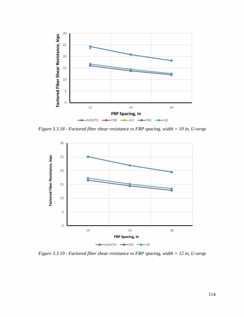
114
Figure 3.3.18 - Factored fiber shear resistance vs FRP spacing, width = 10 in, U-wrap
Figure 3.3.19 - Factored fiber shear resistance vs FRP spacing, width = 12 in, U-wrap
0
5
10
15
20
25
30
12 14 16 Fact
ore
d F
iber
Sh
ear
Res
ista
nce
, kip
s
FRP Spacing, in
AASHTO CNR ACI ISIS UK
0
5
10
15
20
25
30
14 16 18
Fact
ore
d F
ibe
r R
esi
stan
ce, k
ips
FRP Spacing, in
AASHTO ISIS UK

115
Figure 3.3.20 - Unfactored fiber shear resistance, U-wrap, continuous
Figure 3.3.21 - Factored fiber shear resistance, U-wrap , continuous
0
5
10
15
20
25
30
35
40
Un
fact
ore
d F
iber
Sh
ear
Res
ista
nce
, kip
s
AASHTO CNR ACI ISIS UK
0
5
10
15
20
25
30
35
Fact
ore
d F
iber
Sh
ear
Res
ista
nce
, kip
s
AASHTO CNR ACI ISIS UK

116
Figure 3.3.22 - Effect of strip spacing on U-wrap and 2 sided wraping, wf = 6 in
Figure 3.3.23 - Effect of strip spacing on U-wrap and 2 sided wraping, wf = 8 in
0
5
10
15
20
25
8 1 0 1 2
Shea
r C
apac
ity,
kip
s
Strip Spacing, in ACI U-Wrap ACI 2sided CNR 2sided CNR U-Wrap
0
5
10
15
20
25
1 0 1 2 1 4
Shea
r C
apac
ity,
kip
s
Strip Sapcing, in ACI U-Wrap ACI 2sided CNR 2sided CNR U-Wrap
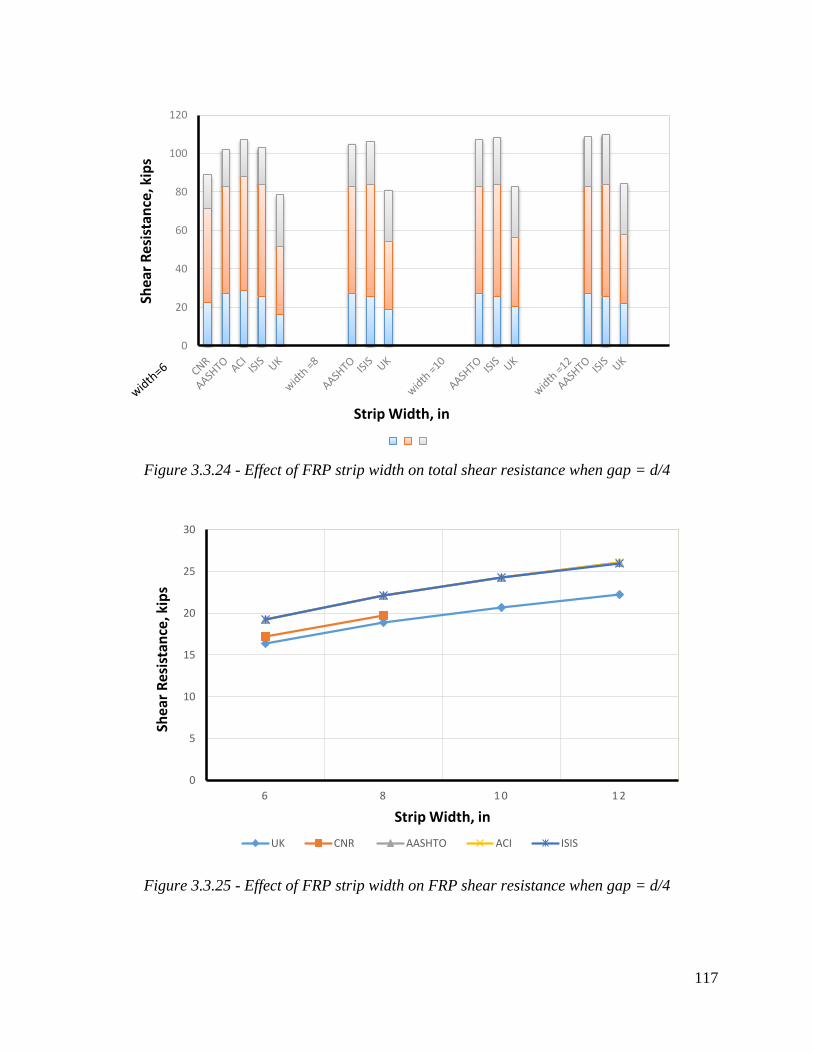
117
Figure 3.3.24 - Effect of FRP strip width on total shear resistance when gap = d/4
Figure 3.3.25 - Effect of FRP strip width on FRP shear resistance when gap = d/4
0
20
40
60
80
100
120
Shea
r R
esis
tan
ce, k
ips
Strip Width, in
0
5
10
15
20
25
30
6 8 1 0 1 2
Shea
r R
esis
tan
ce, k
ips
Strip Width, in
UK CNR AASHTO ACI ISIS

118
Figure 3.3.26 - Effect of the ratio of dfrp/d on Unfactored FRP shear resistance
Figure 3.3.27 - Effect of beam height on total shear resistance, steel stirrup spacing = 9 in
0
5
10
15
20
25
30
35
40
45
0 . 6 2 0 . 7 7 0 . 9 2
Un
fact
ore
d F
RP
Sh
ear
Re
sist
ance
, kip
s
dfrp/d Ratio
AASHTO ACI ISIS UK
0
20
40
60
80
100
120
140
160
180
CN
R
AA
SHTO
AC
I
ISIS
UK
CN
R
AA
SHTO
AC
I
ISIS
UK
CN
R
AA
SHTO
AC
I
ISIS
UK
h = 25 h = 30 h = 35
Tota
l Sh
ear
Res
ista
nce
, kip
s
Beam Height, in
Steel concrete FRP

119
Figure 3.3.28 - Effect of beam height on total shear resistance, steel stirrup spacing = 12 in
Figure 3.3.29 - Effect of beam height on total shear resistance, steel stirrup spacing = 15 in
0
20
40
60
80
100
120
140
160
180
CN
R
AA
SHTO
AC
I
ISIS
UK
CN
R
AA
SHTO
AC
I
ISIS
UK
CN
R
AA
SHTO
AC
I
ISIS
UK
h = 25 h = 30 h = 35
Tota
l Sh
ear
Res
ista
nce
, kip
s
Beam Height, in
Steel concrete FRP
0
20
40
60
80
100
120
140
160
CN
R
AA
SHTO
AC
I
ISIS
UK
CN
R
AA
SHTO
AC
I
ISIS
UK
CN
R
AA
SHTO
AC
I
ISIS
UK
h = 25 h = 30 h = 35
Tota
l Sh
ear
Re
sist
ance
, kip
s
Beam Height, in
Steel concrete FRP

120
Figure 3.3.30 - Effect of beam height on FRP shear resistance, kips steel stirrup spacing = 9 in
Figure 3.3.31 - Effect of beam height on steel shear resistance steel stirrup spacing = 9 in
0
10
20
30
40
50
60
CN
R
AA
SHTO
AC
I
ISIS
UK
CN
R
AA
SHTO
AC
I
ISIS
UK
CN
R
AA
SHTO
AC
I
ISIS
UK
h = 25 h = 30 h = 35
FRP
Sh
ear
Rei
stan
cec,
kip
s
Beam Height, in
FRP
0
10
20
30
40
50
60
CN
R
AA
SHTO
AC
I
ISIS
UK
CN
R
AA
SHTO
AC
I
ISIS
UK
CN
R
AA
SHTO
AC
I
ISIS
UK
h = 25 h = 30 h = 35
Stee
l Sh
ear
Res
ista
nce
, kip
s
Beam Height, in
Steel

121
Figure 3.3.32 - Effect of beam height on concrete shear resistance, steel stirrup spacing = 9 in
3.4 FRP Confinement Strengthening of RC/PC Bridge Members
3.4.1 Introduction
As with previous sections, the items considered for review and comparison in this section are
based on the organization of ACI 440.2R-08. These items include:
Design considerations
Strength reduction factors
Maximum FRP strain due to confinement
FRP stress limits
Design procedures and analysis
3.4.2 Design considerations
3.4.2.1 Strength reduction factors
Table 3.4.1 presents strength reduction factors recommended for use by different codes. Most
range from 0.65-0.75, although, as discussed in previous sections, how these factors are applied
in design is not consistent among codes.
0
10
20
30
40
50
60
70
80
CN
R
AA
SHTO
AC
I
ISIS
UK
CN
R
AA
SHTO
AC
I
ISIS
UK
CN
R
AA
SHTO
AC
I
ISIS
UK
h = 25 h = 30 h = 35
Co
ncr
ete
Shea
r R
esis
tan
ce, k
ips
Beam Height, in
concrete

122
Table 3.4.1 - Strength reduction factor
Code Reduction factor
AASHTO
Reduction factor: Confinement = 0.65
Resistance factor: Spiral = 0.75
Ties = 0.65
CNR Reduction factor for FRP = 0.90
UK Concrete: 0.67
ISIS
Concrete: 0.75
Steel: 0.90
CFRP (embedded in fl equation): 0.56
ACI Spiral: 0.75
Ties: 0.65
3.4.2.2 Maximum FRP strain due to confinement
3.4.2.2.1 CNR
Failure of an RC confined member may occur by fiber rupture. However, beyond a critical value
of hoop strain, the concrete loses effective confinement as it expands laterally and axial strength
and stiffness are no longer enhanced with the FRP. As a result, according to CNR, failure of the
FRP-confined RC member is also reached when the FRP strain reaches a value of 0.4 % or
above.
3.4.2.2.2 AASHTO
Similar to CNR, AASHTO specifies a FRP strain limit of 0.004 when used for confinement of
axial compression members. For comparison, Table 3.4.2 presents other strain limits depending
on the type of stresses applied to the section.
3.4.2.2.3 ACI
ACI introduces the following expression to calculate the maximum confinement strain:
(3.4.1 – ACI eq. 12-6)
The parameter accounts for the geometry of the section and can be taken as 1.0 for circular
cross sections. To prevent excessive cracking and potential loss of concrete integrity, the strain
calculated in Equation 3.4.1 should be limited to the value given in equation 3.4.2 (ACI eq. 12-
7):
(3.4.2 – ACI eq. 12-7)

123
3.4.2.2.4 ISIS
As with CNR and AASHTO, ISIS specifies a maximum confinement strain of 0.004 in the
Canadian building code.
(3.4.3 – ISIS eq. 6-2b)
The bridge code, however, does not include specific limits on FRP hoop strain, but rather
imposes a material reduction factor, .
(3.4.4 – ISIS eq. 6-2a)
Taking , and considering a typical case of MBrace CF130 FRP
with and , the resulting factored strain becomes 0.0094, a value
which is close to the ACI limit of 0.01.
3.4.2.2.5 TR55
Note that although TR55 specifies a maximum strain fixed value of 0.004, which matches the
AASHTO and CNR values, this is in fact for the case of shear. When axial confinement is
considered, however, the hoop strain limit is specified as 0.01. This value corresponds to an
effective enhanced cube strength of .
3.4.2.2.6 Summary - Maximum FRP strain due to confinement
A summary of the FRP strain limits for confined sections is presented in Table 3.4.2. As shown,
most are from 0.003-0.005.

124
Table 3.4.2 Maximum FRP strain due to confinement
Code Maximum Strain due to Confinement
AASHTO
axial compression: 0.004
axial tension: 0.005
Max. design (axial tension) completely wrapped:
Combined axial compression & bending: 0.003
ACI
CNR
ISIS
Building Code: 0.004
Bridge Code: no limit provided
UK Confinement: 0.010
Shear: 0.004
3.4.2.3 FRP stress limits
Limits for confinement stress are generally a function of the stress–strain model used by a
particular code. AASHTO adopts a bilinear model similar to that of ISIS. AASHTO takes a
minimum strain limit of 600 psi to reflect the fact that confinement pressure effectiveness is
attained after a certain level of ductility is achieved. Note that AASHTO’s maximum
confinement stress introduces errors for the case of rectangular columns (D becomes the
diagonal length instead of the radius). The errors are tolerated by AASHTO since they are on the
conservative side.
ACI and CNR both assume a two-stage stress-strain model; an initial parabolic stage to represent
unconfined concrete behavior, followed by a linear stage for confined behavior. The maximum
confined stress limits are identical for both codes, while the minimum limits vary slightly.
TR55 discusses several stress-strain behavior models and recommends a model proposed by
Lillistone and Jolly (1997). The general expression for FRP confined concrete stress is presented
in equation 3.4.3 (TR55 eq. 8.3).
(3.4.5 –TR55 eq. 8.3)

125
where:
Initial tangent modulus of concrete
(3.4.6 –TR55 eq. 8.4)
Post-crushing tangent modulus of concrete
(3.4.7 –TR55 eq. 8.5)
(3.4.8 –TR55 eq. 8.6)
(3.4.9 –TR55 eq. 8.7)
To evaluate the maximum confinement pressure, TR55 recommends equation 3.4.10 (TR55
8.16):
(3.4.10 –TR55 eq. 8.16)
Table 3.4.3 summarizes minimum and maximum confined stress limits.
Table 3.4.3 FRP stress limits
Code Minimum Confined Stress Maximum Confined Stress
AASHTO 600 psi
CNR Confinement is effective if:
ACI
ISIS
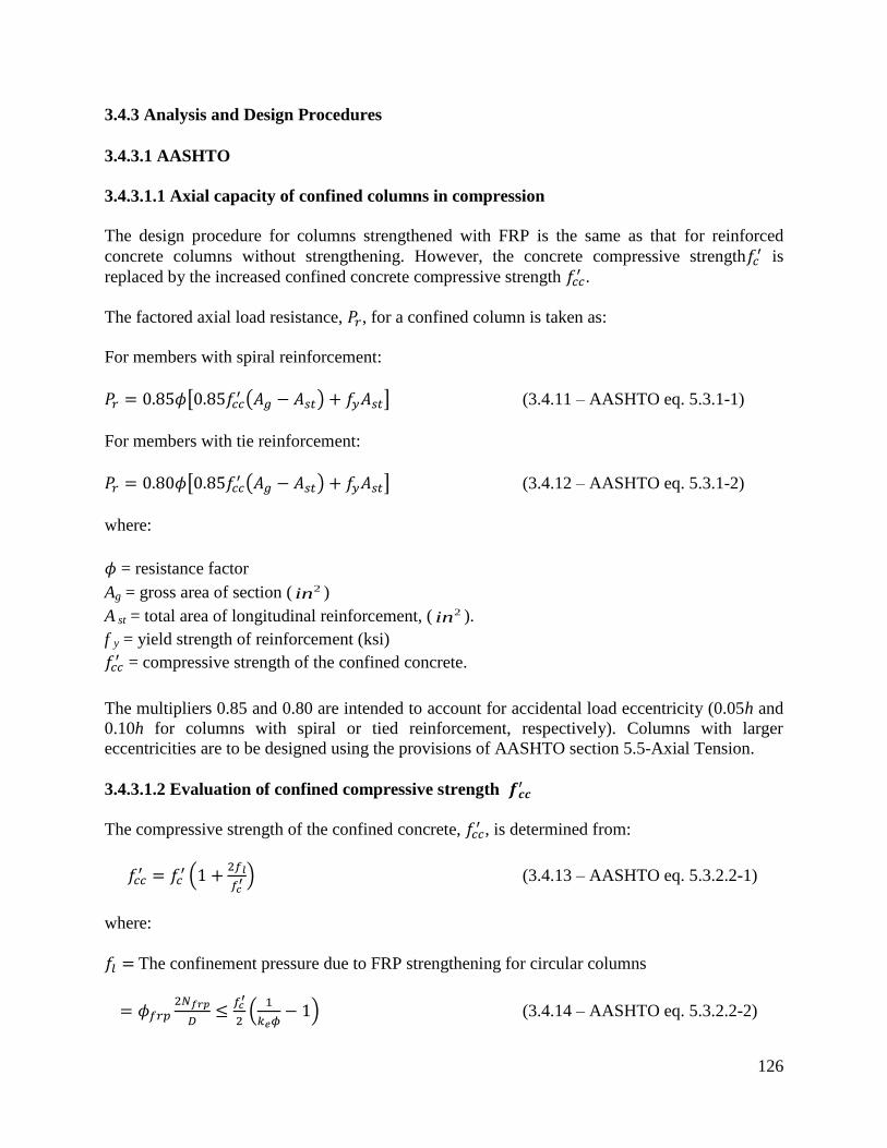
126
3.4.3 Analysis and Design Procedures
3.4.3.1 AASHTO
3.4.3.1.1 Axial capacity of confined columns in compression
The design procedure for columns strengthened with FRP is the same as that for reinforced
concrete columns without strengthening. However, the concrete compressive strength is
replaced by the increased confined concrete compressive strength .
The factored axial load resistance, , for a confined column is taken as:
For members with spiral reinforcement:
(3.4.11 – AASHTO eq. 5.3.1-1)
For members with tie reinforcement:
(3.4.12 – AASHTO eq. 5.3.1-2)
where:
= resistance factor
Ag = gross area of section ( 2in )
A st = total area of longitudinal reinforcement, ( 2in ).
f y = yield strength of reinforcement (ksi)
= compressive strength of the confined concrete.
The multipliers 0.85 and 0.80 are intended to account for accidental load eccentricity (0.05h and
0.10h for columns with spiral or tied reinforcement, respectively). Columns with larger
eccentricities are to be designed using the provisions of AASHTO section 5.5-Axial Tension.
3.4.3.1.2 Evaluation of confined compressive strength
The compressive strength of the confined concrete, , is determined from:
(3.4.13 – AASHTO eq. 5.3.2.2-1)
where:
The confinement pressure due to FRP strengthening for circular columns
(3.4.14 – AASHTO eq. 5.3.2.2-2)

127
= strength reduction factor applied for unexpected eccentricities
= 0.80 for tied columns, and
= 0.85 for spiral columns.
= Strength per width of FRP reinforcement corresponding to a strain of 0.004
= 0.65
For rectangular columns, the diameter D is taken as the smaller dimension of the width and
depth. When equation 3.4.14 (AASHTO eq. 5.3.2.2-2) is applied to rectangular columns after
replacing D with the smaller dimension of the rectangular section, the factored axial strength
estimated from equation 3.4.11 or 3.4.12 (AASHTO 5.3.1-1 or 5.3.1-2) is conservative. The
calculated gain in strength provided by the confinement of a rectangular section is very little
compared to that attainable for circular section. As a result, neither minimum nor maximum
limits are specified for rectangular sections, since the attainable confinement pressure, which
relies on ductility development, is very limited for rectangular columns.
3.4.3.2 ACI
3.4.3.2.1 Axial capacity of confined columns in compression
ACI provides an expression similar to AASHTO to evaluate the axial capacity of confined
columns. The confined stress-strain behavior model adopted by ACI is based on the stress-strain
model developed by Lam and Teng (2003). The expressions used to evaluate axial design
capacity for spiral and tied columns are provided in Equations 3.4.15a and 3.4.15b (ACI 12-1a &
12-1b). These equations are follow ACI 318 column design equations, but concrete compressive
strength is replaced with the confined compressive strength
.
For nonprestressed columns with steel tie reinforcement:
(3.4.15a – ACI eq. 12-1a)
For nonprestressed with tie reinforcement:
(3.4.15b – ACI eq. 12-1b)
3.4.3.2.2 Stress –strain model for confined reinforced concrete columns
The Lam and Teng (2003) model adopted by ACI is shown in Figure 3.4.1. Equation 3.4.16a
provides the general expression for concrete stress for the nonlinear/unconfined portion as well
as the linear/confined portion. Equation 3.4.16b evaluates the slope for the linear portion of the
stress-strain model, . Equation 3.4.16c evaluates the transition strain between the nonlinear
and linear portions of the stress-strain curve. Equations 3.4.1 and 3.4.2 are discussed in section
3.4.2.2.3.

128
Figure 3.4.1 – ACI stress-strain model for FRP-confined concrete (Lam and Teng, 2003a)
(3.4.16a – ACI eq. 12-2a)
where:
The slope of the linear portion of the stress-strain model for FRP confined concrete, psi.
(3.4.16b – ACI eq. 12-2b)
(3.4.16c – ACI eq. 12-2c)
(3.4.1 – ACI eq. 12-6)
(3.4.2 – ACI eq. 12-7)
3.4.3.2.3 Evaluation of confined compressive strength
(3.4.17 – ACI eq. 12-3)
(3.4.18 – ACI eq. 12-4)
(3.4.19 – ACI eq. 12-5)
= Strain efficiency factor (accounts for the possibility of premature failure of FRP)
= 0.586 for CFRP

129
Figure 3.4.2 – Equivalent circular cross section (Lam and Teng 2003)
D is the diameter of a circular column. For noncircular cross sections, an equivalent circular
cross section with diameter D equal to the diagonal of the rectangular cross section is used. The
equivalent D value for a rectangular column cross section is presented in equation 3.4.20 (ACI
12-8):
(3.4.20 – ACI eq. 12-8)
For circular cross sections, the shape factors and appearing in Equations 3.4.1 and 3.4.17
above can be taken as 1.0. For rectangular cross sections, and are expressed in Equation
3.4.21 (ACI eq. 12-9) and 3.4.22 (ACI eq. 12-10) respectively. Their values depend on two
parameters: the side-aspect ratio h/b (see Figure 3.4.2), and the ratio of the effective area of the
confined concrete to the total area of the concrete section . The ratio is evaluated in
Equation 3.4.23 (ACI eq. 12.11.
(3.4.21 – ACI eq. 12-9)
(3.4.22 – ACI eq. 12-10)
(3.4.23 – ACI eq. 12-11)
3.4.3.2.4 Serviceability considerations
ACI stipulates that the transverse strain in the concrete should remain below its cracking strain at
service load levels, which is to be taken as an equivalent concrete compressive stress limit of
0.65fc’. ACI also states that the service stress in the longitudinal steel should remain below
0.60fy to avoid plastic deformation under sustained or cyclic loads.

130
3.4.3.3 ISIS
3.4.3.3.1 Axial capacity of confined columns in compression
The analysis considered in this document is based on the S6-06 bridge code equations and
procedure. The factored axial resistance of a section in compression, , is given by Equation
3.4.24 (ISIS eq. 6.5a):
(3.4.24 - ISIS eq. 6-5a)
where:
= 0.75
= 0.9
= 0.85 – 0.0015 0.67 (3.4.25 – ISIS eq. 5-1)
3.4.3.3.2 Evaluation of the confined compressive strength
The model used in S6-06 to evaluate the confined compressive strength is given by equation
3.4.26 (ISIS eq. 6-3). This equation provides a reasonably conservative estimate of , based on
the research by Thériault and Neale (2000); Teng et al., (2002), and Bisby et al. (2005).
(3.4.26 – ISIS eq. 6-3)
where:
Confinement pressure due to FRP strengthening at ultimate capacity (MPa)
(3.4.27 – ISIS eq. 6-2a)
Diameter of a circular column, or diagonal of a rectangular column provided that the
section edges are rounded, , (see figure 3.4.2), and .
3.4.3.4 CNR
3.4.3.4.1 Axial capacity of FRP-confined members under concentric or slightly eccentric
force
Confinement action on reinforced concrete columns becomes significant only after cracking of
the concrete and yielding of the steel reinforcement when increased lateral expansion occurs;
prior to concrete cracking, the FRP is practically unloaded.

131
Ultimate strength design requires that both the factored design axial load, , and the factored
axial capacity, , satisfy the following equation:
(3.4.28 – NCR eq. 4.39)
For non-slender FRP confined members, the factored axial capacity can be calculated as follows:
(3.4.29 – NCR eq. 4.40)
where:
partial factor taken equal to 1.10
member cross-sectional area
design strength of confined concrete
area of existing steel reinforcement
yield strength of existing steel reinforcement
3.4.3.4.2 Evaluation of the confined compressive strength
The design strength, , of the confined concrete is evaluated as follows:
(3.4.30 – CNR eq. 4.41)
where:
the design strength of unconfined concrete
the effective confined lateral pressure. For effective confinement, use
0.05.
3.4.3.4.3 Evaluation of the confined lateral pressure
The effective confined lateral pressure, , is a function of the member cross section and FRP
configuration, as indicated in the following equation:
(3.4.31 – CNR eq. 4.42)
where:
A coefficient of efficiency (≤1), defined as the ratio of the volume, , of the
effectively confined concrete and the volume, , of the concrete member (neglecting the
area of existing internal steel reinforcement).
The confined lateral pressure.

132
(3.4.32 – CNR eq. 4.43)
The geometric strengthening ratio as a function of section shape (circular or rectangular)
and FRP configuration (continuous or discontinuous wrapping).
Young's modulus of the FRP in the direction of fibers.
A reduced FRP design strain.
(3.4.33 – CNR eq. 4.47)
Environmental conversion factor (CNR Table 3-4)
Partial factor (CNR Table 3-2)
(3.4.34 – CNR eq. 4.44)
3.4.3.4.4 Evaluation of
The coefficient of horizontal efficiency, , depends on the cross-section shape. The coefficient
of vertical efficiency, , depends on the FRP configuration. Regardless of the section shape, the
efficiency coefficient, , is used when fibers are spirally installed with an angle with respect
to the member cross-section. is evaluated using equation 3.4.35 (CNR eq. 4.46).
(3.3.35 – CNR eq. 4.46)
For reinforced concrete columns confined using continuous wrapping, For the case of
discontinuous FRP wrapping, FRP strips are installed with a center-to-center spacing of , and
clear spacing of (see Figure 3.4.3). A reduction in confinement effectiveness occurs due to
the diffusion of stresses (approximately at 45°) between two subsequent wrappings. The
reduction is independent of column cross section shape. The coefficient of vertical efficiency,
, can be evaluated using the following expression:
(3.3.36 – CNR eq. 4.45)
where:
the minimum cross sectional dimension of the member
( for discontinuous wrapping

133
Figure 3.4.3 – Elevation view of circular member confined with FRP strips (CNR)
For circular cross sections subjected to either concentric or slightly eccentric axial load,
confinement is most effective and = 1.0. For members with square or rectangular cross
sections, FRP-confinement produces only marginal increases in the member’s compressive
strength, and CNR specifies additional special limitations in this case; for example, the
strengthening effect of FRP confinement is neglected for rectangular cross sections having b/d >
2, or max{b, d}> 35.4 in (900 mm) unless otherwise demonstrated in experimental tests.
In CNR, similar to other codes, for rectangular cross sections, the effectively confined concrete
area is taken as a fraction of the overall concrete cross section, due to the “arch effect” as shown
in Figure 3.4.4. Such an effect depends on the corner radius . CNR recommends the following
minimum limit to :
(3.3.37 – CNR eq. 4.49)
For rectangular cross sections, the coefficient of horizontal efficiency, , accounts for the arch
effect and is evaluated as follows:
(3.3.38 – CNR eq. 4.51)
Figure 3.4.4 – Confinement of rectangular sections (CNR)

134
3.4.4 Summary
Code results are compared in Figures 3.4.5 - 3.4.34. Results in the figures are calculated with
the following assumptions: a circular cross section is considered with a diameter of 26 inches
and a square cross section with side lengths of 23 in (both columns have the same area of 530
in2). When the effects of
are evaluated, FRP wrapping is taken as 3 plies with a total
thickness of 0.02 in (0.51 mm). Here, BASF MBrace CF130 CFRP is considered. When the
amount of CFRP is varied from 1, 2, 3, 4, and 5 plies, is taken as 4 ksi, and the corresponding
CFRP thicknesses are 0.0065, 0.013, 0.0195, 0.026, and 0.033 respectively (0.17, 0.33, 0.50,
0.66, 0.83mm). Moreover, for sake of comparison, for AASHTO results, the minimum
confinement pressure limit is ignored. Figures 4.5-4.10 present the effect of changing on the
axial capacity of a square column with different reinforcement ratios (0.02, 0.03, and 0.04).
Factored (including applicable reduction factors) and unfactored (excluding applicable reduction
factors from calculations) axial loads are evaluated. Also note that for TR55, reduction factors
are embedded and only the partial safety factor for concrete could be removed for the unfactored
cases.
It was found that the unfactored results are very similar among codes, and as expected, when the
effect of various reduction factors are included, greater differences emerge. Here, CNR is least
conservative while the other codes show, in general, closer agreement, with AASHTO and TR55
(as expected, as some implicit reduction factors are present, as noted above) most conservative.
It was also found that axial capacity is more sensitive to reinforcement ratio at lower values of
than higher values; at a compressive strength of 8 ksi, no increase in axial load capacity is
observed with an increase of from 0.02 to 0.04.
In Figures 3.4.11-3.4.16, the effect of changing on circular column capacity with different
reinforcement ratios is examined. As shown, although trends are similar, the circular column
generally has greater capacity then the corresponding square column of the same area.
Considering the unfactored case, ACI generally has the highest capacity. However, for the
factored cases, CNR produces the greatest capacity.
In Figures 3.4.17-3.4.22, the effect of number of plies on the axial capacity of square columns is
shown. In these figures, it can be seen that, for the factored case, CNR has the highest capacity
while ACI is most conservative. However, the codes converge to similar values for the
unfactored case. Figures 3.4.23- 3.4.28 illustrate the effect of changing the number of plies on
the axial load capacity of circular columns. For circular columns, axial capacity was more
sensitive to then the amount of FRP confinement. For the circular column, AASHTO, ISIS
and TR55 are most conservative (as compared to ACI for square columns), while CNR is least
conservative in both cases. Figures 3.4.29 and 3.4.30 present the effect of number of plies on
axial capacity. It can be seen that increasing the number of layers has little effect on improving
column axial capacity for both circular and square columns, and AASHTO and ISIS (both bridge
codes) produce similar results that are slightly more conservative as compared to ACI and CNR.
Figures 3.4.31 and 3.4.32 show the effect of changing on circular and square column capacity,
while Figure 3.4.33 compares circular and square column results. As shown earlier, increasing
f‘c clearly increases axial capacity, while the bridge codes (AASHTO and ISIS) are slightly
conservative in predicting the axial capacity of circular columns, and TR55 is most conservative

135
for square columns. Due to the reduction of effective area of confinement, square columns
clearly have lower axial capacity than a corresponding circular column. It is also clear that ACI
and CNR produce similar results for circular columns. Figure 3.4.34 shows the effect of
changing the number of plies on axial load capacity, for both circular and rectangular columns.
ACI and CNR provide higher capacities for circular columns while for square columns, ACI is
conservative. For both circular and square columns, AASHTO and ISIS produce similar results.
In summary, the following general observations can be made. The different codes produce more
consistent values of capacity when is varied than when ply number is varied. This is because
changing the number of plies results in different FRP stress and strain limits imposed by
different codes, which becomes the underlying cause of lack of agreement. Only a small change
in axial capacity occurred when ply number changed from 1 to 5, while similarly changing
resulted in large differences in capacity. Overall, CNR is least conservative for most cases,
while AASHTO and ISIS produce close results for most cases.
Figure 3.4.5 - Effect of changing fc' on factored axial load resistance, square column,
Figure 3.4.6 - Effect of changing fc' on unfactored axial load resistance, square column,
0
500
1000
1500
2000
2500
3000
3500
4000
4 . 0 5 . 0 5 . 5 6 . 0 7 . 0 8 . 0
CNR ACI ISIS UK AASHTO
Axi
al L
oad
Cap
acit
y,
f'c, ksi
0
500
1000
1500
2000
2500
3000
3500
4000
4 . 0 5 . 0 5 . 5 6 . 0 7 . 0 8 . 0
CNR ACI ISIS UK AASHTO

136
Figure 3.4.7 - Effect of changing fc' on factored axial load resistance, square column,
Figure 3.4.8 - Effect of changing f‘c on unfactored axial load resistance, square column,
0
500
1000
1500
2000
2500
3000
3500
4000
4 . 0 5 . 0 5 . 5 6 . 0 7 . 0 8 . 0
CNR ACI ISIS UK AASHTO
0
500
1000
1500
2000
2500
3000
3500
4000
4 . 0 5 . 0 5 . 5 6 . 0 7 . 0 8 . 0
CNR ACI ISIS UK AASHTO

137
Figure 3.4.9 - Effect of changing f‘c on factored axial load resistance, square column,
Figure 3.4.10 - Effect of changing f‘c on unfactored axial load resistance, square column,
0
500
1000
1500
2000
2500
3000
3500
4000
4 . 0 5 . 0 5 . 5 6 . 0 7 . 0 8 . 0
CNR ACI ISIS UK AASHTO
0
500
1000
1500
2000
2500
3000
3500
4000
4500
4 . 0 5 . 0 5 . 5 6 . 0 7 . 0 8 . 0
CNR ACI ISIS UK AASHTO

138
Figure 3.4.11 - Effect of changing f‘c on factored axial load resistance, circular column,
Figure 3.4.12 - Effect of changing fc' on unfactored axial load resistance, circular column,
0
500
1000
1500
2000
2500
3000
3500
4000
4 . 0 5 . 0 5 . 5 6 . 0 7 . 0 8 . 0
CNR ACI ISIS UK AASHTO
0
500
1000
1500
2000
2500
3000
3500
4000
4500
5000
4 . 0 5 . 0 5 . 5 6 . 0 7 . 0 8 . 0
CNR ACI ISIS UK AASHTO

139
Figure 3.4.13 - Effect of changing fc' on factored axial load resistance, circular column,
Figure 3.4.14 - Effect of changing fc' on unfactored axial load resistance, circular column,
0
500
1000
1500
2000
2500
3000
3500
4000
4 . 0 5 . 0 5 . 5 6 . 0 7 . 0 8 . 0
CNR ACI ISIS UK AASHTO
0
500
1000
1500
2000
2500
3000
3500
4000
4500
5000
4 . 0 5 . 0 5 . 5 6 . 0 7 . 0 8 . 0
CNR ACI ISIS UK AASHTO
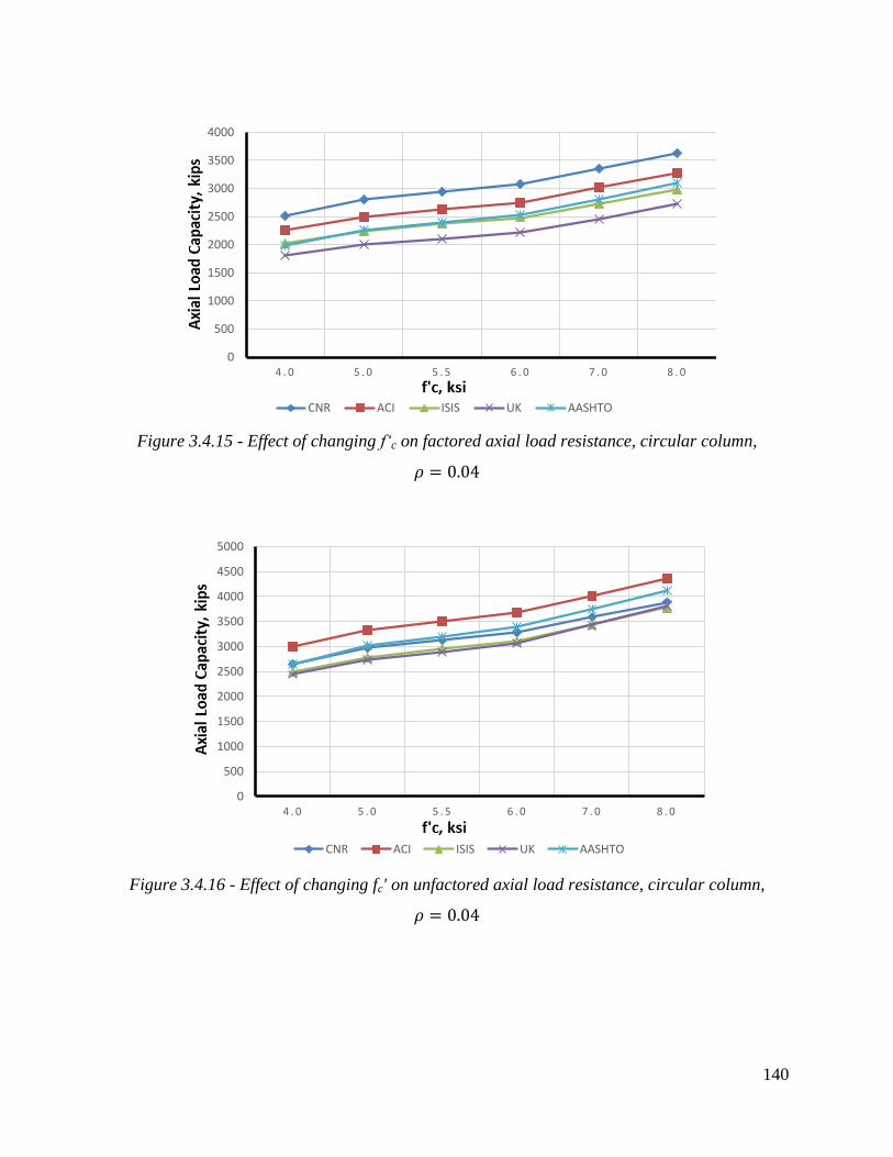
140
Figure 3.4.15 - Effect of changing f‘c on factored axial load resistance, circular column,
Figure 3.4.16 - Effect of changing fc' on unfactored axial load resistance, circular column,
0
500
1000
1500
2000
2500
3000
3500
4000
4 . 0 5 . 0 5 . 5 6 . 0 7 . 0 8 . 0
CNR ACI ISIS UK AASHTO
0
500
1000
1500
2000
2500
3000
3500
4000
4500
5000
4 . 0 5 . 0 5 . 5 6 . 0 7 . 0 8 . 0
CNR ACI ISIS UK AASHTO

141
Figure 3.4.17 - Effect of changing number of plies on factored axial load resistance, square
column,
Figure 3.4.18 - Effect of changing number of plies on unfactored axial load resistance, square
column,
0
500
1000
1500
2000
2500
3000
1 2 3 4 5
CNR ACI ISIS UK AASHTO
0
500
1000
1500
2000
2500
3000
1 . 0 2 . 0 3 . 0 4 . 0 5 . 0
CNR ACI ISIS UK AASHTO

142
Figure 3.4.19 - Effect of changing number of plies on factored axial load resistance, square
column,
Figure 3.4.20 - Effect of changing number of plies on unfactored axial load resistance, square
column,
0
500
1000
1500
2000
2500
3000
1 . 0 2 . 0 3 . 0 4 . 0 5 . 0
CNR ACI ISIS UK AASHTO
0
500
1000
1500
2000
2500
3000
1 . 0 2 . 0 3 . 0 4 . 0 5 . 0
CNR ACI ISIS UK AASHTO
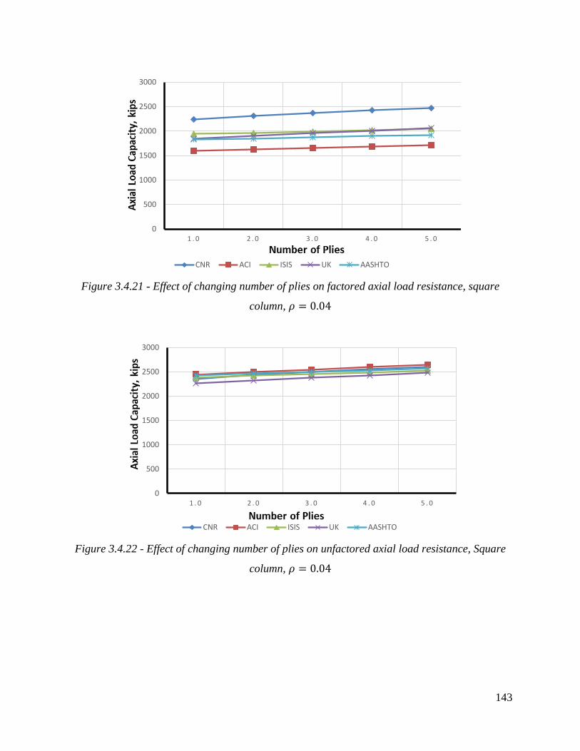
143
Figure 3.4.21 - Effect of changing number of plies on factored axial load resistance, square
column,
Figure 3.4.22 - Effect of changing number of plies on unfactored axial load resistance, Square
column,
0
500
1000
1500
2000
2500
3000
1 . 0 2 . 0 3 . 0 4 . 0 5 . 0
CNR ACI ISIS UK AASHTO
0
500
1000
1500
2000
2500
3000
1 . 0 2 . 0 3 . 0 4 . 0 5 . 0
CNR ACI ISIS UK AASHTO

144
Figure 3.4.23 - Effect of changing number of plies on unfactored axial load resistance, circular
column,
Figure 3.4.24 - Effect of changing number of plies on factored axial load resistance, circular
column,
0
500
1000
1500
2000
2500
3000
3500
4000
1 . 0 2 . 0 3 . 0 4 . 0 5 . 0
CNR ACI ISIS UK AASHTO
0
500
1000
1500
2000
2500
3000
3500
4000
1 . 0 2 . 0 3 . 0 4 . 0 5 . 0
CNR ACI ISIS UK AASHTO

145
Figure 3.4.25 - Effect of changing number of plies on unfactored axial load resistance, circular
column,
Figure 3.4.26 - Effect of changing number of plies on factored axial load resistance, circular
column,
0
500
1000
1500
2000
2500
3000
3500
4000
1 . 0 2 . 0 3 . 0 4 . 0 5 . 0
CNR ACI ISIS UK AASHTO
0
500
1000
1500
2000
2500
3000
3500
4000
1 . 0 2 . 0 3 . 0 4 . 0 5 . 0
CNR ACI ISIS UK AASHTO

146
Figure 3.4.27 - Effect of changing number of plies on unfactored axial load resistance, circular
column,
Figure 3.4.28 - Effect of changing number of plies on factored axial load resistance, circular
column,
0
500
1000
1500
2000
2500
3000
3500
4000
1 . 0 2 . 0 3 . 0 4 . 0 5 . 0
CNR ACI ISIS UK AASHTO
0
500
1000
1500
2000
2500
3000
3500
4000
1 . 0 2 . 0 3 . 0 4 . 0 5 . 0
CNR ACI ISIS UK AASHTO

147
Figure 3.4.29 - Effect of changing number of plies on axial load capacity, circular column,
Figure 3.4.30 - Effect of changing number of plies on axial load capacity, square column,
0
500
1000
1500
2000
2500
CNR ACI ISIS UK AASHTO
1 2 3 4 5
0
500
1000
1500
2000
2500
CNR ACI ISIS UK AASHTO
1 2 3 4 5

148
Figure 3.4.31 - Effect of changing f‘c on axial load capacity, circular column,
Figure 3.4.32 - Effect of changing f‘c on axial load capacity, square column,
0
500
1000
1500
2000
2500
3000
3500
CNR ACI ISIS UK AASHTO
4 5 5.5 6 7 8
0
500
1000
1500
2000
2500
3000
3500
CNR ACI ISIS UK AASHTO
4 5 5.5 6 7 8

149
Figure 3.4.33 - Effect of changing f‘c on axial load capacity, both circular and rectangular
columns,
Figure 3.4.34 - Effect of changing number of plies on axial load capacity, both circular and
rectangular columns,
0
500
1000
1500
2000
2500
3000
3500
4 5 5.5 6 7 8 4 5 5.5 6 7 8
CNR ACI ISIS UK AASHTO
0
500
1000
1500
2000
2500
1 2 3 4 5 1 2 3 4 5
CNR ACI ISIS UK AASHTO
Circular Square

150
3.5 Witness Panels
As further discussed throughout Chapter 4, witness panels are often part of the FRP system
design. The panels are used as test panels to verify the adequacy of the FRP installation. As
such, they are to be produced on-site and exposed to the same construction and weathering
conditions as the strengthening system. Some codes recommend the use of witness panels in
general, while others suggest that this decision should be left to the project engineer. Although
there are no universal guidelines to their use, in general, as the size, complexity, and importance
of the strengthening project increases, the benefits to witness panel fabrication become more
compelling. The panels may be actual areas on the structure itself that are similar in character to
the strengthened areas. In this case, additional strengthening material is applied on other areas of
the structure for later testing. Alternatively, the panels may be smaller, portable specimens apart
from the structure. As the panels may remain available for use for long periods of time, they can
be used only to verify initial quality of the installation but long-term performance characteristics
as well.
Typical witness panel sizes are from 6 in – 24 in2, and are best if placed on the structure itself in
different locations. In general, the number of panels increases with project complexity as well as
the size of the strengthened area. As such, careful planning in the design phase of the project is
necessary to decide upon the number and type of panels (i.e. on or off of the structure), and if on
the structure, panel placement. Additional detail is provided in Chapters 4 and 8.

151
CHAPTER 4: PROVISIONS FOR INSTALLATION, QC, AND MAINTENANCE
4.1 Introduction
This chapter presents a review of field installation provisions of CFRP strengthening systems
detailed in the six international codes considered in Chapter 3 (ACI-440.2R-08; ISIS Manual 4;
AASHTO FRP Guide Specification; JSCE Recommendations; TR55; and CNR-DT 200).
Section 4.2 concerns installation procedures and related matters including shipping, storage, and
handling of FRP system components as well as contractor qualifications to perform the work
needed. Section 4.3 covers all quality assurance/quality control aspects of FRP installation
including inspection, evaluation and acceptance criteria. Section 4.4 covers maintenance and
repair including inspection, assessment, and repair techniques.
4.2. Installation of CFRP Strengthening Systems
4.2.1 Introduction
The review of installation procedures is based on the framework presented in the available
guidelines, and includes the following items:
FRP shipping, handling, and storage
Contractor qualification Installation procedures
4.2.2 Shipping, storage, and handling
4.2.2.1 ACI
4.2.2.1.1 Shipping
In ACI, packaging, labeling, and shipping for thermosetting resin materials are to be controlled
by the Code of Federal Regulations 49 (CFR 49). Many materials are classified as corrosive,
flammable, or poisonous in Subchapter C (CFR 49) under “Hazardous Materials Regulations.”
As such, FRP system constituent materials are to be packaged and shipped in a manner that
conforms to all applicable federal and state packaging and shipping codes and regulations.
4.2.2.1.2 Storage
To preserve critical properties and maintain safety while storing FRP materials, ACI suggests
that manufacturer’s recommendations should be followed. Of particular concern are reactive
curing agents, hardeners, initiators, catalysts, and cleaning solvents which have special safety-
related requirements, and are to be stored in a manner recommended by the manufacturer as well
as OSHA. Catalysts and initiators (usually peroxides) should be stored separately.
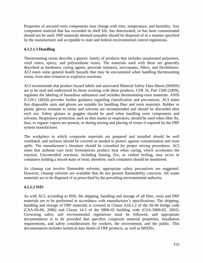
152
Properties of uncured resin components may change with time, temperature, and humidity. Any
component material that has exceeded its shelf life, has deteriorated, or has been contaminated
should not be used. FRP materials deemed unusable should be disposed of in a manner specified
by the manufacturer and acceptable to state and federal environmental control regulations.
4.2.2.1.3 Handling
Thermosetting resins describe a generic family of products that includes unsaturated polyesters,
vinyl esters, epoxy, and polyurethane resins. The materials used with them are generally
described as hardeners, curing agents, peroxide initiators, isocyanates, fillers, and flexibilizers.
ACI notes some general health hazards that may be encountered when handling thermosetting
resins, from skin irritation to explosive reactions.
ACI recommends that product hazard labels and associated Material Safety Data Sheets (MSDS)
are to be read and understood by those working with these products. CFR 16, Part 1500 (2009),
regulates the labeling of hazardous substances and includes thermosetting-resin materials. ANSI
Z-129.1 (2010) provides further guidance regarding classification and precautions. ACI states
that disposable suits and gloves are suitable for handling fiber and resin materials. Rubber or
plastic gloves resistant to resins and solvents are recommended and should be discarded after
each use. Safety glasses or goggles should be used when handling resin components and
solvents. Respiratory protection, such as dust masks or respirators, should be used when fiber fly,
dust, or organic vapors are present, or during mixing and placing of resins if required by the FRP
system manufacturer.
The workplace in which composite materials are prepared and installed should be well
ventilated, and surfaces should be covered as needed to protect against contamination and resin
spills. The manufacturer’s literature should be consulted for proper mixing procedures. ACI
notes that ambient cure resin formulations produce heat when curing, which accelerates the
reaction. Uncontrolled reactions, including fuming, fire, or violent boiling, may occur in
containers holding a mixed mass of resin; therefore, such containers should be monitored.
As cleanup can involve flammable solvents, appropriate safety precautions are suggested.
However, cleanup solvents are available that do not present flammability concerns. All waste
materials are to be disposed of as prescribed by the prevailing environmental authority.
4.2.2.2 ISIS
As with ACI, according to ISIS, the shipping, handling and storage of all fiber, resin and FRP
materials are to be performed in accordance with manufacturer’s specifications. The shipping,
handling and storage of FRP materials is covered in Clause A16.1.2 of the S6-06 bridge code
(CSA-S6-06, 2006) and Clause 14.3 of the S806-02 building code (CSA-S806-02, 2002).
Governing safety and environmental regulations must be followed, and appropriate
documentation is to be provided that specifies composite material properties, installation
requirements, and safety considerations for workers, the environment, and the public. This
documentation includes technical data sheets of FRP products, as well as MSDSs.

153
4.2.2.2.1 Shipping
ISIS states that FRP materials are to be packaged and shipped in a manner that conforms to
applicable packaging and shipping regulations, with particular concern to thermosetting resin
materials that are classified as corrosive, flammable or poisonous, that must follow appropriate
regulations for hazardous materials. It is the duty of the contractor and supplier to ensure that the
packaging and shipping methods used do not negatively impact material properties and
performance. All FRP components must be shipped with their respective MSDSs. ISIS
recommends that all components of the FRP system are inspected upon delivery to the
construction site, and the use of opened or damaged containers should only proceed with written
authorization by the project engineer.
4.2.2.2.2 Storage
Proper storage of FRP components is in a clean, dry area, sheltered from the sun, which is well
ventilated and temperature controlled and in accordance with the manufacturer’s
recommendations. As with ACI, ISIS notes that special safety requirements are required in the
storage and handling of certain components such as reactive curing agents, hardeners, initiators,
catalysts, and cleaning solvent. Catalysts and initiators (e.g., peroxides) should be stored
separately.
The manufacturer is to provide a recommended shelf life within which the properties of the
resin-based materials should continue to meet or exceed the stated performance, and the
contractor must follow these time limits. Materials that have exceeded their shelf life or have
otherwise exhibited signs of deterioration should be disposed of in a manner specified by the
manufacturer.
4.2.2.2.3 Handling
ISIS refers to ACI 503R (1998) for detailed handling information and potential hazards of FRP
components. However, ISIS recommends that special care should be taken to avoid material
contact with water, dust or other contaminants. Moreover, excessive bending, crushing and other
sources of mechanical damage to the fibers must be avoided. All involved in handling
thermosetting resins are to read and understand product labels and MSDSs.
Personal protection precautions include the use of disposable rubber or plastic gloves that are
resistant to resins and solvent penetration (which should be discarded after each use), safety
glasses or goggles, as well as respiratory protection such as dust masks or respirators when
handling resin components and solvents, or for operations where fiber fly, dust, or organic
vapors are present. In poorly ventilated areas, the use of respiratory protection is required,
preferably with a fresh air supply.
Information regarding proper storage, handling, and mixing resin components and potential
hazards should be provided by the manufacturer and made available at the construction site. As
with ACI recommendations, ISIS notes that mixed resin containers should be frequently
monitored since uncontrolled reactions, including fuming and fire, may occur. Similarly, ISIS

154
notes that the workplace should be adequately ventilated, and surfaces covered as needed to
protect against contamination and resin spills.
All waste materials are to disposed of as prescribed by the prevailing environmental authority,
and appropriate precautions observed during clean-up, since some cleaning solvents may be
flammable.
4.2.2.3 AASHTO
AASHTO does not provide specific recommendations for shipping, storage, and handling.
However, NCHRP Report 609 (2008), upon which other AASHTO recommendations are based,
offers the following guidelines.
4.2.2.3.1 Shipping and storage
All FRP system components must be delivered and stored in the original factory-sealed,
unopened packaging with labels identifying the manufacturer, brand name, system identification
number and date. Catalysts and initiators are to be stored separately. All components must be
protected from dust, moisture, chemicals, direct sunlight, physical damage, fire, and
temperatures outside the range specified in system data sheets.
NCHRP 609 notes that typically, temperature in the storage area should be within 50°–75°F
(10°–24°C), unless otherwise noted on the system data sheet, and components should be stored
in a dry environment, unless an acceptable moisture level is specified on the system data sheet. It
is further stated that any component that has been stored in a condition different from that stated
above must be disposed of.
4.2.2.3.2 Handling
All FRP components, but especially fiber sheets, must be handled with care according to
manufacturer recommendations to protect them from damage and to avoid misalignment or
breakage of the fibers. NCHRP 609 notes that higher modulus fibers are more susceptible to
misalignment damage, and therefore should be handled with greater care. After cutting, sheets
shall be either stacked dry with separators, or rolled gently at a radius no tighter than 12 in (305
mm), or as recommended by the manufacturer.
All components of the FRP system, especially resins and adhesives, must be handled with care to
avoid safety hazards, including but not limited to skin irritation and breathing vapors and dusts.
Resin mixing is to be monitored to avoid fuming and production of excessive inflammable
vapors, fire hazards, or violent boiling. It is the contractor's responsibility to ensure that all
components of the FRP system at all stages of work conform to governing environmental and
safety regulations.

155
4.2.2.4 JSCE
4.2.2.4.1 Shipping
JSCE recommends that the handling precautions relating to material deterioration and safety
during delivery, storage, mixing, processing, and use are to be confirmed in advance and strictly
observed. Materials are to be properly shipped and stored to ensure that no deterioration occurs.
4.2.2.4.2 Storage and handling
JSCE notes that continuous fiber sheets and strands are easily damaged before being
impregnated with resin, and some types of continuous fibers may deteriorate if exposed to
ultraviolet light and moisture. Therefore, in general, the FRP materials should be stored in a cool,
dark place without exposure to direct sunlight. As resins are potentially harmful to workers,
resin containers must be sealed securely and stored in a cool, dark place. As resins are also
flammable, fire precautions should be observed and storage quantities kept within limits
prescribed by fire regulations (JSCE references the Japanese Fire Defense Law). JSCE further
recommends that consideration is given to the handling manuals prepared by the material
manufacturer.
4.2.2.5 TR55
TR55 does not have a specific section discussing shipping, storage and handling. The code
requires, however, that all installation related work abide by governing safety laws (TR55
references The Health and Safety at Work Act and The Control of Substances Hazardous to
Health Regulations). The code emphasizes that a certificate of conformity to these laws must be
provided with the materials from the supplier.
TR55 provides few additional material storage guidelines, suggesting that all materials should be
stored and used strictly in accordance with the manufacturer’s instructions, with particular
attention to maintaining proper temperature, and for adhesives, a dry storage area. TR55 suggests
that adhesive and material delivery dates should be recorded, and these items used in rotation
based on the date of arrival. It further states that materials should be stored at the construction
site in a way that damage and contamination are avoided.
4.2.2.6 CNR
4.2.2.6.1 Shipping and storage
CNR notes that each component of the FRP system is to be suitably packaged and transported
according to governing safety regulations. FRP materials are to be stored according to the
recommendations provided by the supplier/manufacturer. CNR notes that the properties of non-
polymerized resins may change over time and are affected by moisture and temperature.
Temperature may also affect the mixture reactivity and properties of polymerized resin. Suitable
environmental conditions for storage are suggested to be from 50–75°F (10-24 °C) and in a dry
environment with less than 20% humidity, unless otherwise suggested by the manufacturer.
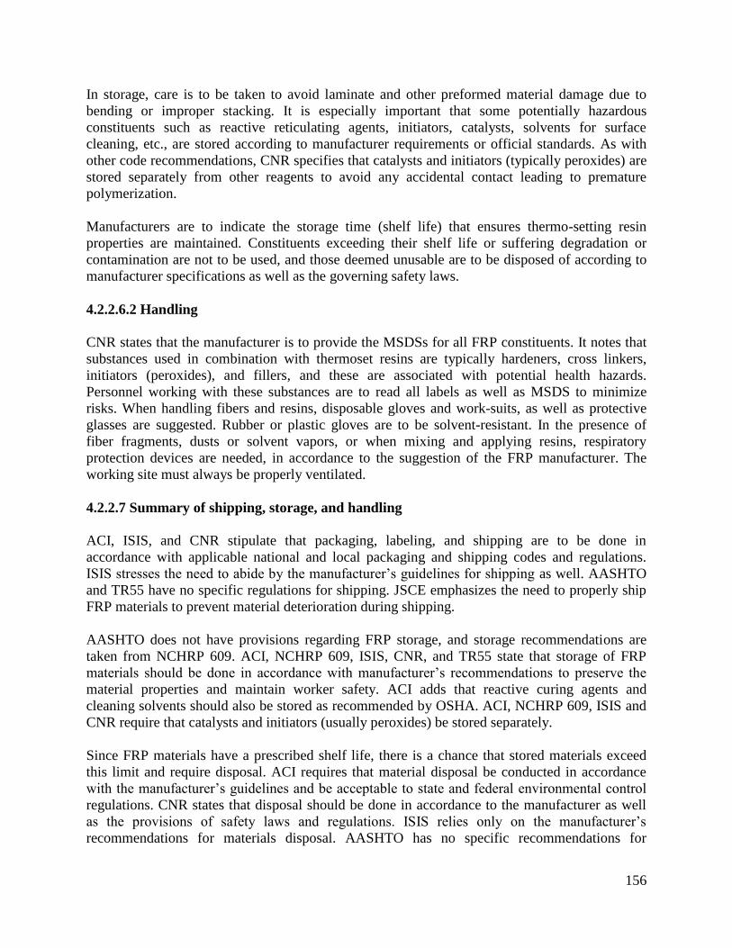
156
In storage, care is to be taken to avoid laminate and other preformed material damage due to
bending or improper stacking. It is especially important that some potentially hazardous
constituents such as reactive reticulating agents, initiators, catalysts, solvents for surface
cleaning, etc., are stored according to manufacturer requirements or official standards. As with
other code recommendations, CNR specifies that catalysts and initiators (typically peroxides) are
stored separately from other reagents to avoid any accidental contact leading to premature
polymerization.
Manufacturers are to indicate the storage time (shelf life) that ensures thermo-setting resin
properties are maintained. Constituents exceeding their shelf life or suffering degradation or
contamination are not to be used, and those deemed unusable are to be disposed of according to
manufacturer specifications as well as the governing safety laws.
4.2.2.6.2 Handling
CNR states that the manufacturer is to provide the MSDSs for all FRP constituents. It notes that
substances used in combination with thermoset resins are typically hardeners, cross linkers,
initiators (peroxides), and fillers, and these are associated with potential health hazards.
Personnel working with these substances are to read all labels as well as MSDS to minimize
risks. When handling fibers and resins, disposable gloves and work-suits, as well as protective
glasses are suggested. Rubber or plastic gloves are to be solvent-resistant. In the presence of
fiber fragments, dusts or solvent vapors, or when mixing and applying resins, respiratory
protection devices are needed, in accordance to the suggestion of the FRP manufacturer. The
working site must always be properly ventilated.
4.2.2.7 Summary of shipping, storage, and handling
ACI, ISIS, and CNR stipulate that packaging, labeling, and shipping are to be done in
accordance with applicable national and local packaging and shipping codes and regulations.
ISIS stresses the need to abide by the manufacturer’s guidelines for shipping as well. AASHTO
and TR55 have no specific regulations for shipping. JSCE emphasizes the need to properly ship
FRP materials to prevent material deterioration during shipping.
AASHTO does not have provisions regarding FRP storage, and storage recommendations are
taken from NCHRP 609. ACI, NCHRP 609, ISIS, CNR, and TR55 state that storage of FRP
materials should be done in accordance with manufacturer’s recommendations to preserve the
material properties and maintain worker safety. ACI adds that reactive curing agents and
cleaning solvents should also be stored as recommended by OSHA. ACI, NCHRP 609, ISIS and
CNR require that catalysts and initiators (usually peroxides) be stored separately.
Since FRP materials have a prescribed shelf life, there is a chance that stored materials exceed
this limit and require disposal. ACI requires that material disposal be conducted in accordance
with the manufacturer’s guidelines and be acceptable to state and federal environmental control
regulations. CNR states that disposal should be done in accordance to the manufacturer as well
as the provisions of safety laws and regulations. ISIS relies only on the manufacturer’s
recommendations for materials disposal. AASHTO has no specific recommendations for

157
materials disposal. However, NCHRP 609, Section 3.4 stipulates that disposal of expired
materials be performed in a manner to protect the environment and follow the manufacturer’s
recommendations as stated in the MSDS.
Storage temperature, moisture, and other considerations are discussed with varying details
among different codes. AASHTO specifies a storage temperature of 50-70oF (10-21
oC), a dry
enclosure protected from dust, moisture, direct sun, and the risk of fire or damage. CNR
recommends the same temperature range as NCHRP 609, but requires a dry environment with a
moisture not to exceed 20% or as recommended by the manufacturer. ACI has no specific stated
temperature or moisture recommendations but suggests following the recommendations of the
manufacturer. TR55 states that storage temperature range is to be in accordance with the
manufacturer, while JSCE places emphasis on fire protection of the storage facility based on
limits prescribed by the Fire Defense Law. JSCE adds several requirements for storage such as
maintaining a cool temperature and a dark environment with no direct exposure to sunlight.
ACI, NCHRP Report 609, ISIS, and CNR require that manufacturer’s recommendations are to be
used when handling FRP materials to protect against health risks from skin exposure or fume
inhalation. ACI refers to CFR 16, Part 1500 for regulations on hazardous substance labeling, and
ANSI Z-129.1 for further guidance regarding classifications and precautions. ACI, ISIS, and
CNR require individuals handling FRP system components to wear disposable suites, gloves, eye
protection, and respirators for safe handling of the materials. The three codes recommend the use
of a well-ventilated work place. TR55 and JSCE have no coverage of FRP materials handling.
ACI and ISIS state that for cleanup and disposal, the use of cleanup solvents that do not present a
high flammability risk is advisable. The codes require that all waste materials be contained and
disposed as prescribed be the prevailing environmental authority.
4.2.3 Contractor qualifications
4.2.3.1 ACI
ACI suggests that the FRP system installation contractor should demonstrate competency for
surface preparation and application of the FRP system to be installed. This competency can be
demonstrated by providing evidence of training and documentation of related work previously
completed, or by an actual demonstration of surface preparation and installation. It is
recommended that the FRP system manufacturer or its authorized agent should train the
contractor’s application personnel in the installation procedure for the specific system to be used.
4.2.3.2 ISIS
ISIS stipulates that the contractor is responsible for providing the training of his staff and shall
provide proof of the qualification or experience of his staff to the project engineer. The staff,
which includes the installation crew, supervisors, and safety officers, must be properly trained on
the specific tasks within their responsibility. For example, a site safety officer must be trained on
the course of action in the case of accident in accordance with materials safety regulations
provided in the MSDSs.

158
4.2.3.3 AASHTO
As with ACI, AASHTO recommends that FRP application must be performed by a contractor
trained in accordance with the installation procedures specified by the manufacturer. For further
information, AASHTO references NCHRP 609 (2008). According to NCHRP 609, the
manufacturer/supplier may be pre-qualified for each FRP system to be installed, after providing
the following information:
System data sheets and MSDS for all components of the FRP system;
Documentation of a minimum of 5 years’ experience with the FRP system, or 25 documented
similar field applications with acceptable reference letters from respective owners;
Documentation of a minimum of 50 test data sets from an independent agency approved by
the owner verifying the mechanical properties, aging and environmental durability of the
proposed FRP system, and;
Documentation of the availability of a comprehensive hands-on training program for each
FRP system that can be taken by the staff of the contractor/applicator.
The owner may also require the manufacturer/supplier to provide a specified number of samples
of the components and the complete FRP system for in-house or independent testing prior to
qualification. The training program conducted by the manufacturer/supplier should provide
hands-on experience with surface preparation and installation of the same FRP system for which
the certificate is issued. The contractor/applicator may be pre-qualified by the owner for each
FRP system, after providing documentation of a minimum of 3 years’ experience or 15 similar
field applications with acceptable reference letters from respective owners, and a certificate of
completed training from the manufacturer/supplier for at least one staff member who will be
present on site throughout the project.
4.2.3.4 JSCE
JSCE recommends that work should be performed under the supervision of an engineer who has
thorough knowledge of FRP strengthening. However, the code does not specifically discuss
criteria for qualifying a contractor.
4.2.3.5 TR55
TR55 recommends that various issues should be taken into account when selecting a contractor.
In particular, it suggests that the contractor provide evidence of experience in strengthening
work, has quality assurance procedures in place, and is accredited and audited in accordance with
ISO 9002. TR55 further suggests that the contractor should be a member of the Concrete Repair
Association or has a record of successful projects involving the installation of composites.
Moreover, the contractor should provide a detailed statement of the method which will be used to
install the composites as well as an assessment of the risks involved. This should include
discussion of the procedure which will be used to minimize the risks to the workforce and to any
other persons (especially children) who may be affected by the work. The contractor's personnel
should be supplied with the correct protection equipment for use when handling the materials,
and trained and qualified in the application technique specified by the manufacturer of the

159
system. Finally, the contractor should provide a safe means of access to the work location and
maintain an environment suitable for the successful use of structural adhesives.
4.2.3.6 CNR
CNR does not provide specific recommendations for qualifying a contractor. However, it defines
several responsibilities of the contractor as follows. The contractor is to obtain the material
indicated by the designer through suppliers/manufacturers who guarantee the quality of their
products, and is to ensure that the products are accompanied by technical data sheets, reporting
both mechanical and physical characteristics, and possibly laboratory test certificates. Finally,
the contractor is to see that these products comply with the provisions indicated by the designer,
and if the material with the indicated requirements is not available, the contractor is to work with
the designer to find a viable alternative.
4.2.3.7 Summary of contractor qualifications
ACI, ISIS, and TR55 require that the contractor provide evidence of training on the FRP
strengthening system to be used, as well as provide evidence of past experience of similar
projects. CNR and JSCE do not provide any specific contractor qualifications requirements.
AASHTO refers to NCHRP 609 for recommendations with regard to contractor qualifications.
This report offers a comprehensive list of qualification requirements for the supplier and the
contractor with specifics such as documentation to verify the required years of experience for the
supplier (5 years). The report generally requires the submittal of documented evidence for all
items needed for qualification (see Article 4.2.3.3, above).
4.2.4 Installation Procedures
4.2.4.1 ACI
ACI notes that procedures for installing FRP systems have been developed by the system
manufacturers and often differ between systems. In addition, installation procedures can vary for
the same system, depending on the type and condition of the structure. ACI recommends that
deviations from the procedures developed by the manufacturer should not be allowed without
manufacturer approval.
4.2.4.1.1 Temperature, humidity, and moisture considerations
ACI emphasizes that temperature, relative humidity, and surface moisture at the time of
installation can affect the performance of the FRP system. It suggests that primers, saturating
resins, and adhesives should generally not be applied to cold or frozen surfaces. When the
surface temperature of the concrete surface falls below a minimum level as specified by the FRP
system manufacturer, improper saturation of the fibers and improper curing of the resin
constituent materials can occur, compromising the integrity of the system. It suggests that a non-
contaminating heat source can be used to raise the ambient and surface temperatures during
installation.

160
With regard to moisture, ACI states that resins and adhesives should generally not be applied to
damp or wet surfaces unless they have been formulated for such applications. Moreover, FRP
systems should not be applied to concrete surfaces that are subject to moisture vapor
transmission. ACI warns that the transmission of moisture vapor from a concrete surface through
the uncured resin materials typically appears as surface bubbles and can compromise the bond
between the FRP system and the substrate.
4.2.4.1.2 Equipment
Some installation procedures specify unique equipment designed for the application of that
particular system. This equipment can include resin impregnators, sprayers, lifting/positioning
devices, and winding machines. ACI suggests that all equipment should be clean and in good
operating condition. All supplies and equipment should be available in sufficient quantities to
allow continuity in the installation project and quality assurance.
4.2.4.1.3 Surface preparation
Successful strengthening with FRP systems is dependent on a sound concrete substrate and
proper preparation of the concrete surface, as an improperly prepared surface can result in
debonding or delamination. Although ACI presents general guidelines intended to all externally
bonded FRP systems, it notes that specific guidelines for a particular FRP system should be
obtained from the manufacturer. For general methods of concrete repair and surface preparation,
ACI refers to ACI 546R (2004) and ICRI 03730 (2008). ACI suggests that the FRP system
manufacturer should be consulted to ensure compatibility of the FRP system with the materials
used for repairing the concrete substrate, if necessary. If corrosion-related concrete deterioration
is detected, ACI suggests that the cause of the corrosion be addressed, and the associated
deterioration repaired before application of the FRP system.
To repair cracks, those wider than 0.010 in (0.3 mm) can be pressure injected with epoxy before
FRP installation, in accordance with ACI 224.1R (2007). Cracks of smaller width may require
resin injection or sealing to prevent corrosion of existing reinforcement. ACI refers to ACI
224.1R (2007) for crack-width limitations based on different exposure conditions.
ACI classifies surface preparation into two major categories: bond-critical or contact-critical.
Bond-critical applications require an adhesive bond between the FRP and the concrete, and
usually involve systems for flexural or shear strengthening. ACI suggests that surface
preparation for bond-critical applications should be in accordance with ACI 546R (2004) and
ICRI 03730 (2008). A summary of recommendations is given as follows:
The surface on which the FRP system is to be applied should be free of loose or unsound
materials, and where fibers wrap around the corners of rectangular cross sections, the corners
should be rounded to a minimum 0.5 in (13 mm) radius to prevent stress concentrations in
the FRP as well as voids between the FRP and the concrete. This applies to both vertical and
horizontally-oriented corners. Note that ACI does not specifically mention allowing an
existing or created chamfered edge to substitute for a rounded edge. Roughened corners can

161
be smoothed with putty. Inside corners and concave surfaces may require special detailing to
ensure bond between the FRP system and the concrete.
Consideration should be given to removing obstructions and embedded objects in the
concrete before installing the FRP system, and surface preparation can be accomplished with
either abrasive or water-blasting techniques. Bug holes and other small surface voids should
be completely exposed during surface profiling. After profiling, the surface should be
cleaned and protected.
The concrete surface should be prepared to a minimum concrete surface profile (CSP) 3, as
defined by ICRI surface profile chips, and localized out-of-plane variations, including form
lines, should not exceed 1/32 in (~1 mm) or the tolerances recommended by the FRP system
manufacturer.
Localized variations can be removed by grinding, before abrasive or water blasting, or can be
smoothed over using resin-based putty if variations are small. Bug holes and voids should be
filled with resin-based putty. All surfaces to be strengthened should be as dry as
recommended by the FRP system manufacturer.
Contact-critical applications only require close contact between the FRP and concrete, and are
generally reserved for confinement strengthening. In applications involving confinement, the
surface should be prepared such that continuous contact between the concrete and the FRP
system is maintained. Moreover, surfaces to be wrapped should be flat or convex, and large
surface voids should be patched. Materials with low compressive strength and elastic modulus,
such as plaster, should be removed.
4.2.4.1.4 Mixing of resins
According to ACI, the manufacturer should supply recommended batch sizes, mixture ratios,
mixing methods, and mixing times, and all mixing should be done according to the
manufacturer’s recommendations. Resin components should be at the proper temperature and
mixed until there is a uniform and complete mixing of components. Resins should be mixed for
the prescribed mixing time and visually inspected for uniformity of color. As resin components
are often contrasting colors, ACI notes that full mixing is usually achieved when color streaks
are eliminated. Resin mixing should be in quantities sufficiently small to ensure that all mixed
resin can be used within the resin’s pot life.
4.2.4.1.5 Application
ACI recommends that FRP systems be selected with consideration for their impact on the
environment, including emission of volatile organic compounds and toxicology.
Where required, primer should be applied to all areas on the concrete surface where the FRP
system is to be placed. Here, primer should be placed uniformly at the manufacturer’s specified
rate of coverage. Once applied, the primer should be protected from dust, moisture, and other
contaminants before applying the FRP system. Putty should be used in an appropriate thickness
and sequence with the primer as recommended by the FRP manufacturer, and only to fill voids
and smooth surface discontinuities. Rough edges or trowel lines of cured putty should be ground
smooth, and primer and putty should be cured as specified by the FRP system manufacturer

162
before applying the FRP resin or adhesive. Note that after the putty and primer are cured, the
FRP system manufacturer may require additional surface preparation before the application of
the saturating resin or adhesive.
The use of solvents to clean the FRP surface before applying a coating is not recommended due
to the damaging effect that solvents may have on resin, and the FRP system manufacturer should
approve the use of any solvent wipe. Coatings should be periodically inspected and maintenance
provided as needed to ensure the effectiveness of the coating.
Wet lay-up FRP systems are typically installed by hand using dry fiber sheets and a saturating
resin, and should use the manufacturer’s installation recommendations. Generally, saturating
resin should be applied uniformly to all prepared surfaces where the system is to be placed, then
the reinforcing fibers should be gently pressed into the resin. Entrapped air between layers
should be released or rolled out before the resin sets. Sufficient resin should be applied to
achieve full saturation of the fibers, and successive layers of saturating resin and fibers should be
placed before the complete cure of the previous resin layer. If previous layers have cured,
interlayer surface preparation, such as light sanding or solvent application as recommended by
the system manufacturer, may be required.
Wrapping machines are primarily used for concrete columns. Machine-applied systems can use
resin pre-impregnated tows or dry-fiber tows; prepreg tows are impregnated with saturating resin
off-site and delivered to the work site as spools, while dry fibers are impregnated at the job site
during the winding process. ACI emphasizes that the FRP system manufacturer’s
recommendations should be followed in all application steps. After wrapping, prepreg systems
should be cured at an elevated temperature in accordance with the manufacturer’s
recommendations.
Precured systems include shells, strips, and open grid forms that are typically installed with an
adhesive. General recommendations are as follows. Surfaces to be bonded should be clean and
prepared in accordance with the manufacturer’s recommendations, with a minimum concrete
surface profile (CSP) of 3 (ICRI 03732). The adhesive should then be applied uniformly at the
rate recommended by the FRP manufacturer. After the precured sheets are placed into the wet
adhesive, entrapped air between layers should be released or rolled out before the adhesive sets.
Any protective coatings that are used should be compatible with the FRP strengthening system
and applied in accordance with the manufacturer’s recommendations.
4.2.4.1.6 Alignment of FRP materials
Proper FRP alignment is critical, as even small variations in angle (as little as 5 degrees) from
that intended can cause a substantial reduction in strength and stiffness. Therefore, materials
should be handled such that correct fiber straightness and orientation are preserved, and
deviations in ply orientation should be made only if approved by the project engineer. Moreover,
kinks, folds, waviness, or other forms of substantial material malformation should be reported for
evaluation.

163
4.2.4.1.7 Multiple plies and lap splices
Multiple plies may be used, provided that all plies are fully impregnated with resin the shear
strength is sufficient to transfer the shearing load between plies, and the bond strength between
the concrete and FRP system is sufficient. Lap splices may be used for long spans as necessary,
provided that they are staggered, unless otherwise approved by the project engineer. Lap splice
details, including lap length, should be based on testing and installed in accordance with the
manufacturer’s recommendations. Specific guidelines on lap splices are given in ACI Chapter
13.
4.2.4.1.8 Curing
Ambient-cure resins can take several days to reach full cure, and temperature extremes or
fluctuations can retard or accelerate curing time. All resins should be cured according to the
manufacturer’s recommendations, and field modification of resin chemistry should not be
permitted. The cure status of installed plies should be verified to be sufficient before placing
subsequent plies, and the installation of successive layers should be halted if there is a curing
anomaly.
To meet the manufacturer's curing recommendations, FRP systems may require protection such
as tents or plastic screens, during installation and curing against adverse temperatures, direct
contact by rain, dust, or dirt, excessive sunlight, high humidity, and vandalism. If temporary
shoring is required, the FRP system should be fully cured before the shoring is removed. If
damage to the FRP system is suspected during installation, the project engineer should be
notified and the FRP system manufacturer should consulted for evaluation.
4.2.4.2 ISIS
As with ACI, ISIS stresses the importance of following the specific recommendations of the FRP
system manufacturer.
4.2.4.2.1 Temperature, humidity, and moisture considerations
ISIS notes that the temperature, humidity, and dew point at the time of installation can affect the
performance of the FRP system. It suggests that in general, primers, saturating resins and
adhesives should not be applied to cold or frozen surfaces. Per Clause A16.1.3.5 of the S6-06
bridge code, during the installation of the FRP, ambient air and concrete surface temperature
should be 50°F (10°C) or more; the concrete surface temperature should be at least 5°F (3 °C)
higher than the actual dew point; and atmospheric relative humidity should be less than 85%. To
meet these conditions in colder temperatures, it may be necessary to provide a non-
contaminating auxiliary heat source to the FRP material during the installation and curing
processes.
Moreover, resin and adhesive materials should not be applied to wet surfaces unless they are
specifically formulated for this purpose, and FRP materials should not be applied to concrete
164
surfaces that are subject to condensation, vapor transmission, or water ingression unless such
issues are clearly addressed by the system design and the resin systems are specifically
formulated for use in such conditions.
4.2.4.2.2 Equipment
As with ACI, ISIS suggests that all equipment used in the installation process should be clean
and in good operating condition, and should be accessible for inspection by the project engineer.
The contractor should have qualified personnel sufficiently trained to install and operate system-
specific equipment such as resin impregnators, sprayers, lifting/positioning devices, and winding
machines. All materials, and supplies, and personal protective equipment should be available in
sufficient quantities to allow safe construction continuity and quality assurance.
4.2.4.2.3 Surface Preparation
For concrete surface preparation details, ISIS refers to Clause A16.1.4 of the S6-06 bridge code
(2006) and Clause 14.9 of the S806-02 building code (2002). ISIS suggests that the concrete
surface preparation should be inspected and approved by the engineer or the supervisor prior to
the application of the FRP. Some specific recommendations are as follows. ISIS recommends
that the surface preparation should be performed according to the FRP system manufacturer’s
guidelines. Surfaces in good condition may only require cleaning, but all signs of deterioration,
including that caused by steel corrosion, should be repaired prior to the application of the FRP
system. Before the repair process, the concrete surface must be free of particles and pieces that
no longer adhere to the structure, and cleaned from oil and other contaminants. An inspection
and approval of the surfaces is then required before the repair may begin. During the repair, the
concrete surfaces must be repaired or reshaped in accordance with the original section, and
sections with sharp edges must be rounded to a minimum radius of 1.4 in (35 mm), in
accordance with the S6-06 bridge code (2006), before installing the FRP system.
Cracks wider than 0.01 in (0.3 mm) should be pressure injected with epoxy in accordance with
the guidelines of ACI 224.1R (2007), and smaller cracks in aggressive environments may also
require epoxy injection to prevent corrosion of steel reinforcement. All surface repairs should
meet the requirements of the FRP system manufacturer.
For bond-critical applications, the method of surface preparation should depend on the existing
surface condition. A smooth concrete surface can be sandblasted or otherwise abraded until
aggregates become visible according to the relevant preparation recommendations. After blast
cleaning, the surface should be protected within an appropriate amount of time prior to the FRP
installation. Areas that are very rough can be leveled using a material approved by the
manufacturer and/or the engineer, and out-of-plane variations should be within the tolerances
recommended by the FRP system manufacturer, where small holes and voids should be filled
with putty or a mortar polymer. The maximum allowed depth of depressions (see Clause A16.1.4
of the S6-06 bridge code) is shown in Table 4.2.1 (ISIS Table 8.1).

165
Table 4.2.1 – Maximum depth of depressions on the concrete surface
Type of FRP Max. depth for length
of 12 in (0.3 m), in
Max. depth for length of
80 in (2.0 m), in
Plates 0.16 in (4.0 mm) 0.39 in (10.0 mm)
Plates ( ) 0.08 in (2.0 mm) 0.24 in (6.0 mm)
Sheets 0.08 in (2.0 mm) 0.16 in (4.0 mm)
All dirt, oil, existing coatings, or other matter that could interfere with the bond of the FRP
should be removed. The concrete surface must have a tensile and shear strength high enough to
ensure an efficient bonding; Clause A16.1.4 of the S6-06 bridge code requires a minimum tensile
strength of 218 psi (1.5 MPa) as measured by a pull-off tension test in accordance with ASTM
D4541 (2002). Rectangular cross-sections should have corners rounded or reshaped to a
minimum radius of 1.4 in (35 mm), and roughened corners should be smoothed with an epoxy
gel.
All surfaces to which the strengthening system will be applied should be dry according to the
FRP system manufacturer's requirements, and the moisture content should be evaluated
according to the requirements of ACI Standard 503.4 (2003).
For contact-critical applications such as confinement, the surface preparation should guarantee a
continuous contact between the concrete and the FRP confinement system. Rounding of corners,
filling holes and eliminating depressions are most critical.
For all types of applications, if water seepage through the concrete is found, special resins
designed for this bond condition must be used. Both the engineer and the contractor must verify
that the pressures will neither cause debonding nor affect the integrity of the reinforced structure.
If FRP is to be installed underwater, the method to be used must be prescribed in detail according
to the recommendations of the manufacturer and must be approved by the engineer.
4.2.4.2.4 Mixing of resins
When mixing resins, all components should be mixed at a proper temperature and in the correct
ratio until there is uniform and complete mixing and the product is free from trapped air. The
resin mixing should be done in quantities sufficiently small to ensure that all mixed resin will be
used within the resin's pot life.
4.2.4.2.5 Application
ISIS references Clause A16.1.3 of the S6-06 bridge code for FRP application. ISIS recommends
that all materials, including primer, putty, saturating resin and fibers, are part of the same system.
ISIS notes that appropriate installation procedures should depend on the specific FRP system and
the structure for strengthening.
For hand-applied wet lay-up systems, manufacturer recommendations must be followed in all
application steps, and the following additional recommendations are suggested. Putty should be
used only to fill voids and smooth surface discontinuities prior to the application of other
166
materials, and should be used in an appropriate thickness and in sequence with the primer as
recommended by the FRP manufacturer. Primer should be placed uniformly on the prepared
surface at the specified rate of coverage, and should have sufficiently low viscosity to penetrate
the surface of the concrete substrate. Rough putty edges or trowel lines should be smoothed
before installation of the fiber sheets.
Hand-applied, wet lay-up materials include dry as well as pre-impregnated fiber sheets and
fabrics used with a saturating resin applied on site. In the latter case, the saturating resin should
be applied uniformly to all prepared surfaces where the FRP is to be placed. The resin should
have sufficiently low viscosity such that the fiber reinforcement becomes fully impregnated with
resin prior to curing. Once the FRP is applied, entrapped air under the sheet or between layers
should be released or rolled out before the resin sets. In doing so, it is recommended to work the
FRP materials parallel to the fibers, proceeding in one direction from the center or from one
extremity and to avoid any backward and forward movements. A protective finish compatible
with the proposed system should be applied in accordance with the manufacturer’s
recommendations.
When using pre-cured systems (i.e. surface bonded plates), the pre-cured laminate surfaces to be
bonded should be cleaned and prepared in accordance with the manufacturer’s recommendations.
Adhesive should be applied uniformly to the prepared surfaces where the laminates are to be
placed. Care should be taken to use an application method to avoid entrapping air under the
laminate, because such a condition is difficult to detect as well as to rectify. In contrast to hand-
applied, wet lay-up materials, stacking multiple layers of FRP plate is usually not permitted,
except for the overlapping portion of prefabricated L-shaped stirrups. At intersections of FRP
plates, care should be exercised to minimize curvature; grooving the concrete for the layer
underneath is sometimes used to allow full contact between the plate and the concrete surface
underneath.
For FRP material used to wrap the base of a reinforced concrete column that is in contact with
the ground, the wrapping should extend a minimum of 20 in (500 mm) below the ground surface
to prevent water and air infiltration. ISIS also states that FRP stirrup strips for shear
reinforcement must be anchored in a satisfactory manner at both extremities; this anchorage is to
be specified by the designer.
4.2.4.2.6 Alignment of FRP materials
ISIS notes that the alignment of the FRP material is critical, and the ply orientation and stacking
sequence must be specified in the design prior to installation. As with ACI, ISIS specifies that
sheet and fabric materials should be handled in a manner to maintain the fiber straightness and
orientation, as even small variations in the intended orientation angle can cause a reduction in
strengthening. Any observed deviation in angle for an installed FRP are to be approved by the
project engineer.

167
4.2.4.2.7 Multiple plies and lap splices
ISIS allows the use of multiple layers of FRP materials, provided that all layers are fully
impregnated within the resin system, that the resin shear strength is sufficient to transfer the
shearing load between layers, and that the FRP-to-concrete adhesive strength is sufficient.
However, the project engineer or the manufacturer may limit the maximum number of
consecutive layers, and/or define the installation period between successive layers. When several
superposed layers of FRP materials are required, care must be taken not to move or otherwise
disturb the preceding layers where the resin has not set. In the absence of other prescriptions, a
minimum overlap length parallel to the fibers of 6 in (150 mm) is suggested. If an interruption of
the FRP system laying up process occurs, inter-layer surface preparation such as cleaning or light
sanding may be required.
4.2.4.2.8 Curing
FRP materials are to be cured according to the recommendations of the manufacturer. Unless
otherwise specified, ISIS recommends the following curing provisions. A minimum curing time
of 24 hours should be allowed before further work is performed, unless the curing process is
accelerated by heating (via a chemical reactant or other external supply). For the entire curing
duration, the temperature must be maintained above the minimum required curing temperature;
condensation on the surface must be prevented; and chemical contamination from gases, dust or
liquid sprays must be prevented during curing. ISIS notes that although successful rehabilitation
of beams under simulated traffic loads have been reported (Recuero et al., 2004), mechanical
stresses should be minimized during curing.
4.2.4.2.9 Protective coating
When the surface of the FRP materials is sufficiently dry or hard, a protective coating and/or
paint compatible with the installed reinforcement system can be added. A minimum of 24 hours
should be allowed for the protective coating/paint to dry, or as recommended by the
manufacturer. Further, the contractor is required to provide a certificate of compatibility of the
protection system prepared by the FRP manufacturer, and the contractor is to provide a guarantee
for the performance of the proposed protection system for the expected exposure conditions. The
protection system must provide sufficient protection against ultraviolet radiation. It may include
a wearing layer if the FRP reinforcement materials are expected to be subjected to abrasive
effects. The wearing layer must not be considered to be structural reinforcement, and it must be
inspected and maintained regularly. If the FRP reinforcement must be protected against fire, the
protection system proposed must be approved by the engineer, and the contractor or
manufacturer must guarantee its compliance.
4.2.4.3 AASHTO
AASHTO requirements are written in a similar manner to those given by ACI and ISIS.
According to AASHTO, procedures for the installation of FRP systems are developed by the
manufacturer and can vary between different systems. Procedures may also vary depending on
the type and condition of the structure to be strengthened. AASHTO notes that the application of

168
FRP systems will not stop the ongoing corrosion of existing steel reinforcement, and the cause of
any corrosion should be addressed and corrosion-related deterioration should be repaired prior to
application of any FRP system.
4.2.4.3.1 Temperature, humidity, and moisture considerations
When temperatures exceed 90°F, the epoxy may be difficult to apply due to an accelerated
hardening rate. AASHTO thus recommends that work should be scheduled to avoid high
temperatures. If it is necessary to apply epoxy compounds in high temperatures, the work should
be supervised by a person experienced in applying epoxy under such conditions. AASHTO also
notes that epoxy systems formulated for elevated temperatures are available and should be
considered (see ACI 530R-93). At temperatures below 40°F, application difficulties may also
occur due to a deceleration of the rate of curing, and the presence of frost or ice crystals may be
detrimental to the bond between the FRP and the concrete.
4.2.4.3.2 Surface preparation
Prior to FRP application, the concrete surface should be prepared to a minimum concrete surface
profile (CSP) 3. Proper preparation and profiling of the concrete surface is necessary to achieve
the specified bond strength; improper surface preparation can lead to debonding or delamination.
AASHTO recommends that localized out-of-plane variations, including form lines, should not
exceed 1/32 inch or the tolerances recommended by the FRP system manufacturer, whichever is
smaller. Bug holes and voids are to be filled with epoxy putty. It is recommended that surface
preparation be accomplished using abrasive or water-blasting techniques, and all contaminants
that could interfere with the bond between the FRP system and concrete substrate should be
removed. When fibers are wrapped around corners, corners should be rounded to a minimum
radius of 1/2 inch to prevent stress concentrations in the FRP system as well as voids between
the FRP and the concrete. Rough edges can be smoothed by grinding or with putty.
4.2.4.4 JSCE
4.2.4.4.1 Temperature, humidity, and moisture considerations
When bonding or wrapping with continuous fibers, at each stage of the work it should be verified
that environmental conditions are suitable. Suitable conditions for epoxy resin applications are a
9°F (5°C) or higher temperature and humidity no more than 85%. In lower temperatures, the
construction site should be warmed or a low-temperature primer and resin may be used. If the
surface of the concrete is not dry, special primers for wet surfaces should be used. It should also
be verified that the concrete surface preparation is suitably performed; that the mixing and
coating of primer are appropriately performed; and that the mixing and coating of a smoothing
agent are appropriately performed.
To prevent improper hardening of the primer and smoothing agent, the materials should be
applied to a dry surface. After application, the primer and smoothing agent should be allowed to
harden until firm, and should be checked visually and by touch to make sure there is no dust or
moisture on the surface. If there is condensation or other moisture on the surface before initial
169
hardening, indicated by whitening, the area should be wiped with solvent or the effected portion
of primer or smoothing agent removed with sandpaper.
4.2.4.4.2 Surface preparation
Prior to application of FRP, JSCE recommends that construction defects, remarkable
deterioration, and surface cracking in the concrete should be repaired. These defects include
problems such as rock pockets, honeycombs, level differences or other surface imperfections,
which deviate from a smooth surface and can reduce the effectiveness of the FRP strengthening.
When continuous fiber sheets and continuous fiber strands are placed perpendicular to corner
angles, the angles should be rounded by chipping, polishing, or the use of a smoothing agent.
To ensure proper bond between the FRP and the concrete surface, deteriorated layers, oils and
other contaminants should be removed from the surface.
4.2.4.4.3 Application
When using continuous fiber sheets, JSCE notes that it is critical that the sheets are attached with
the specified position, direction, and number of plies. A working diagram matching the actual
structure should be prepared based on the design. The diagram should clearly identify the
reference point for attachment, the overlap splice positions and the number of plies to enable the
sheets to be attached properly. It must also be ensured that the sheet is bonded or sealed securely
to the concrete surface, and that the resin is suitably mixed and applied and has thoroughly
impregnated the sheet. This is particularly important in the overlap splice sections, where the
impregnation resin should thoroughly penetrate between the fibers and sheets. After attaching the
continuous fiber sheets, an inspection should be done visually or through sounding to verify the
absence of lift, swelling, peeling, slackness, wrinkles, and voids in the epoxy resin impregnation.
When using continuous fiber strands, it must be verified that the strand winding interval is
appropriate; the strand winding tension is constant; the strand winding speed is appropriate; the
strands are thoroughly impregnated with resin; that the resin has been suitably mixed and
applied; and that the impregnation resin is cured thoroughly. JSCE notes that if carbon fiber
strands are wound by hand, the tension force applied is not constant, resulting in variations of
stress distribution in the strands after completion. Moreover, since the winding speed is not
constant, there may also be variations in the degree of permeation of the impregnation resin.
These issues may affect the tensile strength of the strands. For these reasons, the use of a
machine to wind the strands, to control the winding interval, tension and speed, is recommended.
JSCE notes that when wrapping FRP around corners, it is important that a sufficient radius of
curvature is maintained, as when the radius of curvature is small, as noted by AASHTO, stress
concentrations occur, decreasing the effective tensile strength of the FRP. In general, the chamfer
radius should be between 0.4 in – 2.00 in (10 mm - 50 mm). However, the type and thickness of
FRP used have a large influence on the necessary chamfer radius.

170
4.2.4.4.4 Lap splices
JSCE states that the required lap length is to be determined through testing in accordance with
JSCE-E 542 (2000). JSCE note that carbon and aramid fiber sheets have been found to require an
overlap splice length of approximately 4 in (100 mm) at the lower stress level produced in the
splice zone and about 8 in (200 mm) for strengthening for shear capacity and ductility. However,
depending on the type of FRP and resin used, the splice strength may be lower than the tensile
strength of the FRP and failure may occur in the bonded layers of the splice even if the overlap
length is long.
When only one layer of continuous fiber sheet is used for reinforcement, variations in overlap
splice strength due to construction errors may significantly influence the splice strength. In such
cases, it is recommended to elongate the overlap splice length and to attach one more layer of
FRP over the splice section. When more than one layer is used, the overlap splices should not be
placed at the same section, since this reduces the overlap splice strength. Overlap splices should
not be placed at locations subjected to large bending moments.
4.2.4.4.5 Curing
After applied, resin should be cured for a suitable period of time before the next sheet is
attached. Before the initial setting of the impregnation resin, JSCE recommends that the surface
should be protected with vinyl sheets from rain, dust, and sudden climatic changes. It must also
be verified that the impregnation resin is cured thoroughly.
4.2.4.4.6 Anchorage length
JSCE notes that an item requiring verification is the end anchorage of FRP, for which it should
be confirmed that the strand is wound with the required number of turns at the section to be
anchored. The required number of turns for anchorage should be determined through testing.
JSCE states that one to two wraps is sufficient anchorage for carbon fiber strands composed of
12,000 filaments.
If mechanical anchorage is to be used, it can be by way of anchor bolts and plates, and should be
verified by confirming that the anchorage detail has sufficient strength to prevent anchorage
failure. JSCE suggests that when reinforcing bridge pier foundations, mechanical anchoring with
anchor plates and bolts may be necessary because attaching FRP sheets to the footing surface is
generally insufficient anchorage. When FRP is bonded to the sides of beams for shear
reinforcement, anchorage should be provided by anchor bolts and plates.
4.2.4.5 TR55
4.2.4.5.1 Temperature, humidity, and moisture considerations
Before application of FRP, the concrete surface should be dry for normal applications. If surface
dryness is not achievable, a suitable epoxy adhesive for non-dry surfaces should be selected.

171
Suitable environmental conditions including temperature, relative humidity and surface moisture
must be maintained during surface preparation, strengthening system application, and the curing
period. During surface preparation, environmental control consists of a system to extract dust
from the work area and the exclusion of any material that might contaminate the prepared
surface. During installation, a clear access path from the adhesive work area to the location of the
concrete surface should be maintained in order to minimize contamination risk. During the
curing period, the adhesive temperature must be maintained within the specified limits. The work
area should be kept dry.
4.2.4.5.2 Surface Preparation
TR55 suggests that a trial run of the surface preparation process should be conducted to
determine the best technique for the FRP system to be used. As with other codes, TR55 notes
that the concrete surface must be cleaned to remove contaminants. Even new concrete should be
cleaned to remove mold release agents and curing membranes. The preparation process should
remove the surface layer to expose small particles of aggregate without causing damage to the
substrate. The surface should not be polished or roughened excessively. Sharp edges, shutter
marks or other irregularities should be removed to achieve a flat surface.
Various preparation techniques can be effective, including wet, dry, and vacuum-abrasive
blasting; high-pressure washing, with or without emulsifying detergents, and using biocides
(where necessary); steam cleaning alone or in conjunction with detergents; and, for smaller
areas, mechanical wire brushing or surface grinding. TR55 warns that special care should be
taken when using some methods, including mechanical impact methods such as needle gunning
and bush hammering, which are often too aggressive and may cause micro-cracks and/or an
irregular concrete texture.
Washing techniques may be ineffective in some cases, and can simply spread the contaminants
further. The use of solvent-based and sodium hydroxide-based products in the form of a gel or
poultice can be effective in drawing out the contaminants, but such products must be then
completely removed from the surface. If wet grit-blasting is done, the concrete surface must be
allowed to completely dry before proceeding. TR55 further recommends vacuum dry-blasting
over "open" blasting, the former of which is safer for workers and the environment.
TR55 states that, prior to FRP installation, defects in the concrete surface should be repaired, and
if cementitious repairs are used, they should be allowed 28 days to cure. TR55 notes that it is
important that the prepared surface should allow application of the resin in a layer of uniform
thickness; the thickness of the adhesive layer is commonly between 0.04 – 0.20 in (1 – 5 mm).
To facilitate this, the surface should be smoothed by removing any steps and filling hollows with
a suitable repair mortar. Minor imperfections in the concrete surface can be treated with epoxy
materials which can be applied in thin layers. The flatness of the surface should be such that the
gap under a 3.3 ft (1 m) straight-edge does not exceed 0.20 in (5 mm). When fabric is to be
wrapped around corners, the corners should be rounded to a minimum radius of 0.6 in (15 mm),
or as recommended by the manufacturer. TR55 notes that some bonding systems require the use
of a primer to be applied once the surface preparation is complete if so, primer should be applied
in strict accordance with the manufacturer's instructions.

172
The final assessment of surface quality can be made with pull-off tests. If primer was used, the
primed surface should be tested. Here, a minimum of three tests are carried out, as described in
BS 1881: Part 207 (1992).
4.2.4.5.3 Mixing of resins
All equipment used for the mixing and application of the adhesive and materials should be kept
clean and maintained in good operating condition, and all operators should be suitably trained in
the use of such equipment. The mixing and application of the adhesive should be in accordance
with the manufacturer's instructions. For accurate mix proportioning, pre-batched quantities of
resins and hardeners should be used. The materials should be mixed thoroughly per the
supplier’s instructions. The volume of adhesive mixed at one time should be such that it may be
applied within the pot life of the adhesive; adhesive remaining at the end of the specified pot life
must be discarded.
4.2.4.5.4 Application
If the concrete surface is to be strengthened using FRP plates, the mixed adhesive is to be applied
to the bonding area by hand, using plastering techniques. The thickness of the adhesive should be
maintained from 0.04 – 0.08 in (1–2 mm). Before applying the adhesive to the FRP plate, the
plate surface should be prepared in accordance with the manufacturer's recommendations; in
general, this involves application of light abrasion and cleaning with a solvent. No additional
treatment is required for materials with an additional peel ply which, upon removal, exposes a
clean surface with the appropriate roughness. The adhesive layer should be applied to the plates
to form a slightly convex profile across the plate. Extra thickness along the center-line helps to
reduce the risk of void formation.
If FRP fabric is to be applied, a hand-held foam roller or brush can be used to apply the bonding
adhesive to the concrete surface. The adhesive layer should be evenly applied to saturate the
concrete surface· and adhere to the FRP. Dry fabric can be directly applied to the resin-saturated
concrete surface without adhesive being applied to the fabric. For wet fabric, the resin must be
applied to the fabric before it is installed. The resin can be applied to the fabric using handheld
foam rollers or brushes, or an impregnation machine.
4.2.4.6 CNR
4.2.4.6.1 Temperature, humidity, and moisture considerations
CNR recommends that FRP should not be installed in very moist environments, as a high degree
of humidity may delay resin curing and affect strengthening effectiveness, especially for wet lay-
up applications. Moreover, FRP should not be applied to substrates having a surface humidity
greater than 10%, as such conditions could delay the penetration of the primer and generate air
bubbles that could compromise bond. Substrate humidity can be evaluated with a hygrometer for
mortar or by employing absorbent paper. FRP material should also not be applied if temperatures
are too low, as resin curing and fiber impregnation could be compromised. It is also
recommended not to install FRP when the concrete surface is heavily exposed to sunlight. CNR

173
suggests that the range of suitable temperature for FRP application is generally within 50-95°F
(10-35°C). In low temperature environments, artificial heat can be provided. If resin curing takes
place under rainy conditions, protective measures should be employed to ensure proper curing.
4.2.4.6.2 Surface preparation
Prior to FRP installation, CNR recommends that the soundness of the concrete substrate is
checked, and in any case, concrete compressive strength should not be less than 2.18 ksi (15
N/mm2) below which the FRP strengthening may not be effective. CNR states that deteriorated
concrete should be removed, and an assessment of the existing steel reinforcing bars should be
made if exposed. Corroded steel bars are to be protected against further deterioration. Once the
deteriorated concrete has been removed, suitable measures taken to prevent further corrosion,
and additional protective measures, if needed, to prevent other sources of concrete degradation
(such as water leakage), concrete restoration using shrinkage-free cement grouts is to be
performed. A concrete surface roughness with profile differences greater than 0.4 in (10 mm) is
to be leveled with a compatible epoxy paste, and specific filling materials are to be used for
unevenness greater than 0.8 in (20 mm). Cracks wider than 0.02 in (0.5 mm) should be stabilized
using epoxy injection methods before FRP strengthening can take place. Once the flatness and
soundness of the concrete is restored sandblasting should be done to provide a roughness of at
least 0.01 in (0.3 mm); level of roughness can be measured by suitable instruments such as a
laser profilometer or an optical profile-measuring device. All inside and outside corners and
sharp edges shall be rounded or chamfered to a minimum radius of 0.8 in (20 mm). Finally, the
concrete surface should be cleaned to remove any dust, laitance, or any other bond-inhibiting
material.
4.2.4.6.3 Application
Proper fibers alignment is to be observed, and waving of FRP reinforcement must be avoided
during installation. If carbon fiber is used and there is potential for direct contact between the
carbon and existing steel reinforcement, insulating material should be installed to prevent
galvanic corrosion. CNR recommends that an anchorage length of at least 8 in (200 mm) be used
for the end portion of FRP systems. Alternatively, mechanical connectors may be used.
4.2.4.6.4 Witness areas
If semi-destructive tests are planned, it is suggested to provide additional strengthening areas
(“witness areas”) in properly selected parts of the structure of size of at least 20 in X 8 in (500
mm x 200 mm), with a minimum extension of 155 in2
(0.1 m2), but not less than 0.5% of the
overall area to be strengthened. Witness areas are to be strengthened at the same time of the main
FRP installation, using the same materials and procedures. In addition, witness areas are to be
exposed to the same environmental conditions of the main FRP system and should be uniformly
distributed on the strengthened structure.

174
4.2.4.6.5 Protective coating
The FRP system should be protected from direct sunlight, which may produce chemical-physical
alterations in the epoxy matrix. This can be achieved with protective acrylic paint, provided that
the composite surface is cleaned with soap beforehand. Alternatively, a better protection can be
achieved by applying a plaster or mortar layer (preferably concrete-based) to the installed
system.
For fire protection, two different solutions may be adopted: the use of intumescent panels or the
application of protective plasters. In both cases, the manufacturer is to indicate the degree of fire
protection provided, as a function of the panel/plaster thickness. The panels, generally based on
calcium silicates, are to be applied directly on the FRP system, provided that fibers will not be
cut during their installation. Fire-protective coatings that can keep the FRP temperature below
176°F (80°C) for 90 minutes are also available.
4.2.4.7 Summary of installation procedures
Coverage of installation procedures varies widely among codes. AASHTO and CNR are
primarily design codes with little coverage of many aspects of FRP installation. The limited
areas that are covered by the two codes include surface preparation of the concrete substrate and
site environmental conditions at the time of installation. CNR covers three additional topics;
minimum width for crack injection repair; lap splices; and temporary protection of the FRP
system during resin curing. AASHTO's lack of coverage is supplemented by NCHRP 609, which
provides description of a recommended installation procedure not found in AASHTO. JSCE is
similarly brief in coverage, and includes site environmental conditions at the time of installation;
surface preparation of the concrete substrate; mixing of resin; and lap splicing. TR55 covers the
same items as JSCE, with the exception of lap splicing. TR55 also adds detail on FRP
application in the form of primer/putty application and wet lay-ups.
The most comprehensive installation procedure detailed in the reviewed codes is provided by
ACI and ISIS. The two codes have similar coverage, although ISIS provides more quantitative
limits. The topics covered by ACI and ISIS include site environmental conditions at installation;
use of equipment; surface preparation; resin mixing; application of the FRP system; protective
coatings; alignment of FRP materials; multiple plies and lap splices; resin curing; and temporary
protection. Comparative summaries are provided in Tables 4.2.2 – 4.2.4. Table 4.2.2 compares
maximum allowable crack width beyond which concrete injection is required as part of surface
repair prior to FRP application. Table 4.2.3 compares the minimum allowable lap splice length.
Table 4.2.4 compares code recommendations for minimum radius for roundness of concrete
corners for FRP application.
Table 4.2.2 – Maximum allowable concrete crack width beyond which injection is required
ACI ISIS CNR
0.01 in
(0.3 mm)
0.01 in
(0.3 mm)
0.02 in
(0.5 mm)

175
Table 4.2.3 – Minimum allowable lap splice length
ISIS JSCE CNR
6 in
(150 mm)
4 in (100 mm) at lower stress levels
8 in (200 mm) for strengthening of
shear capacity and ductility
8 in
(200 mm)
Table 4.2.4 – Minimum radius for roundness of concrete corners
ACI ISIS AASHTO JSCE CNR TR55
0.5 in
(13 mm)
1.4 in
(35 mm)
0.5 in
(13 mm)
0.4 – 2.0 in
(10-50 mm)
0.8 in
(20 mm)
0.6 in
(15 mm)
4.3 Inspection, Evaluation, and Acceptance
4.3.1 Introduction
Section 4.3 reviews inspection procedures, evaluation, and acceptance criteria for the installed
FRP strengthening system. An assessment survey inspection, as part of a long-term maintenance
program, is covered in Section 4.44.
Inspection evaluation procedures cover the materials used, conformance to the strengthening
design plan, and post-installation inspection of the finished product to detect any deficiencies
such as delamination, air bubbles, fiber waviness or misalignment, and adhesion strength.
Evaluation of deficiencies, if any, is conducted based on acceptance criteria that sets limits
between acceptable minor deviations and deficiencies that require corrective repairs.
4.3.2 Inspection
4.3.2.1 ACI
ACI states that FRP systems and all associated work should be inspected as required by
applicable codes. The inspection should be conducted by or under the supervision of the project
engineer or a qualified inspector. The qualified inspector should look for compliance with the
design drawings and project specifications. During the installation of the FRP system, daily
inspection should be conducted and should note, as applicable:
Date and time of installation;
Ambient temperature, relative humidity, and general weather observations;
Surface temperature of concrete;
Surface dryness per ACI 503.4 (2003);
Surface preparation methods and resulting profile using the ICRI-surface-profile-chips;
Qualitative description of surface cleanliness;
Type of auxiliary heat source, if applicable;
Widths of cracks not injected with epoxy;

176
Fiber or precured laminate batch number(s) and approximate location in structure;
Batch numbers, mixture ratios, mixing times, and qualitative descriptions of the appearance
of all mixed resins, including primers, putties, saturants, adhesives, and coatings mixed for
the day;
Observations of progress of resin cure;
Conformance with installation procedures;
Pull-off test results: bond strength, failure mode, and location;
FRP properties from tests of field sample panels or witness panels, if required;
Location and size of any delaminations or air voids; and
General progress of work.
The inspector should provide the inspection records and witness panels. ACI defines witness
panels as structural samples manufactured on site as true representatives of the materials and
FRP system used. They are to be kept under the same conditions as the structure for future
testing and evaluation. In some cases, FRP system is applied to areas of the structure not in need
of strengthening for future testing and assessment. Records and witness panels should be retained
for a minimum of 10 years or a period specified by the project engineer. The installation
contractor should retain sample cups of mixed resin and maintain a record of the placement of
each batch.
4.3.2.2 ISIS
ISIS divides inspection tasks into several phases; inspection of the concrete substrate; materials
inspection; and inspections before installation, during installation, and at completion of the
project.
4.3.2.2.1 Contractor’s QC responsibilities
ISIS requires that the FRP material suppliers, the installation contractors and all others associated
with the FRP strengthening project maintain a comprehensive quality assurance (QA) and quality
control (QC) program (per Annex A16.2 of S6-06 bridge code). Quality assurance (QA) is
achieved through a set of inspections, measurements, and applicable tests to document the
acceptability of the surface preparation and the installation of FRP, and the quality control (QC)
should cover all aspects of the strengthening project, and will depend on the size and complexity
of the project.
The FRP material suppliers are responsible for training the installation crew and as well as
certifying their competency for the surface preparation and installation of the FRP materials.
ISIS notes that only qualified inspectors should be used.
FRP materials should be qualified on the basis of the engineer’s plans and specifications. ISIS
notes that two types of specifications are possible; descriptive or performance. In descriptive
specifications, the engineer specifies the length, width, orientation, installation sequence and
other requirements of a particular, selected FRP material, and perhaps acceptable equivalents. In
performance specifications, the engineer specifies requirements in term of strength, stiffness, or
177
other necessary properties and characteristics, and the contractor is responsible for selecting an
appropriate FRP system and submitting it for approval.
The FRP manufacturer is to provide documentation demonstrating that the proposed system
meets all design requirements such as tensile strength, type of fibers and resin, durability,
resistance to creep, bonding to substrate, and glass transition temperature. Independent tests of
the FRP constituent materials and laminates fabricated with them are essential and should be
mandatory.
Selection of contractors should be based on evidence regarding their qualifications, their
demonstrated skills and ability through experience or training for FRP strengthening projects.
4.3.2.2.2 Inspection of concrete substrate
The concrete surface should be inspected and tested before application of the FRP material. The
inspection should include an examination for surface smoothness, protuberances, holes, cracks,
corners, and other imperfections and characteristics. Pull-off tests should be performed to
determine the tensile strength of the concrete for bond-critical applications, in accordance with
Clause A16.1.4 of the S6-06 bridge code (2006). The degree of surface dryness, including the
potential for condensation, should be in accordance with the criteria established by the FRP
manufacturer.
4.3.2.2.3 Inspection before installation
Inspections of the FRP material is to be conducted before, during and after installation. The
inspection program should cover such aspects such as raw materials, the presence and extent of
delamination, the cure of the installed system, adhesion, laminate thickness, fiber alignment and
material properties.
Before construction, the FRP material supplier should submit a certification and identification of
all FRP materials to be used, and the installation procedure should be submitted with information
on shelf life and resin working time related to temperature. Performance tests on the supplied
materials should be performed according to the QC test plan and should meet the requirements
specified in the engineer’s performance specifications. Testing may include parameters such as
tensile strength, glass transition temperature, gel time, pot life, as well as the adhesive shear
strength.
4.3.2.2.4 Inspection during installation and at completion
During construction, special care should be taken to keep all records on the quantity of mixed
resin during a one-day period, the date and time of mixing, the mixture proportions, and
identification of all components, ambient temperature, humidity, and other factors that may
affect resin properties. These records should also identify the FRP sheets used each day, their
location on the structure, the ply count and direction of application, and all other relevant
information in accordance with Clause A16.2.3.3 of the S6-06 bridge code.

178
Sample cups of mixed resin should be prepared according to a predetermined sampling plan and
retained for testing to determine the level of cure. Sample FRP plate specimens should be
fabricated according to a predetermined sampling plan, under the same ambient conditions and
procedures used to apply the FRP material to the concrete surfaces. Performance tests on these
FRP specimens may be conducted as needed. Moreover, a visual inspection of fiber orientation,
and waviness for specific FRP material systems, should be performed. Fiber misalignment of
more than 5 degrees (1/12 slope) from the specified angle should be reported to the engineer.
4.3.2.2.5 Inspection at completion
At project completion, the inspector is to check for delamination, the overall quality of cured
system, and test for adhesion. Moreover, a record of all final inspection and test results related to
the FRP material should be retained. It should include a description of any delamination and
repairs, on-site bond tests, anomalies and correction reports as well as all test results from
designated testing facilities. Samples of the cured FRP materials should be retained by the
engineer. The required reports and tests are specified in Clause A16.2.3.4 of the S6-06 bridge
code (2006).
4.3.2.3 AASHTO
AASHTO recommends that systems considered for FRP strengthening should be inspected by a
licensed engineer or qualified inspector knowledgeable in FRP systems and installation
procedures. The following should be recorded at the time of installation:
Date and time of installation;
Ambient temperature, relative humidity, and general weather observations and surface
temperature of concrete;
Surface dryness, surface preparation methods and the resulting surface profile using ICRC
surface profile-chips;
Qualitative description of surface cleanliness;
Type of auxiliary heat source, if used;
Widths of cracks not injected with epoxy;
Fiber or pre-cured laminate batch number(s) and approximate locations in the structure where
each was used;
Batch numbers, mixture ratios, mixing times, and qualitative descriptions of the appearance
of all mixed resins, including primers, putties, saturants, adhesives, and coatings mixed for
the day;
Observations of progress of resin curing;
Conformance with installation procedures;
Location and size of any delaminations or air voids;
General progress of work;
Level of resin curing, in accordance with ASTM D2582 (2009);
Adhesion strength.
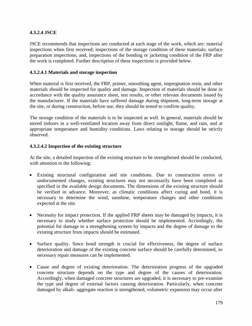
179
4.3.2.4 JSCE
JSCE recommends that inspections are conducted at each stage of the work, which are: material
inspections when first received; inspections of the storage condition of these materials; surface
preparation inspections; and, inspections of the bonding or jacketing condition of the FRP after
the work is completed. Further description of these inspections is provided below.
4.3.2.4.1 Materials and storage inspection
When material is first received, the FRP, primer, smoothing agent, impregnation resin, and other
materials should be inspected for quality and damage. Inspection of materials should be done in
accordance with the quality assurance sheet, test results, or other relevant documents issued by
the manufacturer. If the materials have suffered damage during shipment, long-term storage at
the site, or during construction, before use, they should be tested to confirm quality.
The storage condition of the materials is to be inspected as well. In general, materials should be
stored indoors in a well-ventilated location away from direct sunlight, flame, and rain, and at
appropriate temperature and humidity conditions. Laws relating to storage should be strictly
observed.
4.3.2.4.2 Inspection of the existing structure
At the site, a detailed inspection of the existing structure to be strengthened should be conducted,
with attention to the following:
Existing structural configuration and site conditions. Due to construction errors or
undocumented changes, existing structures may not necessarily have been completed as
specified in the available design documents. The dimensions of the existing structure should
be verified in advance. Moreover, as climatic conditions affect curing and bond, it is
necessary to determine the wind, sunshine, temperature changes and other conditions
expected at the site.
Necessity for impact protection. If the applied FRP sheets may be damaged by impacts, it is
necessary to study whether surface protection should be implemented. Accordingly, the
potential for damage to a strengthening system by impacts and the degree of damage to the
existing structure from impacts should be estimated.
Surface quality. Since bond strength is crucial for effectiveness, the degree of surface
deterioration and damage of the existing concrete surface should be carefully determined, so
necessary repair measures can be implemented.
Cause and degree of existing deterioration. The deterioration progress of the upgraded
concrete structure depends on the type and degree of the causes of deterioration.
Accordingly, when damaged concrete structures are upgraded, it is necessary to pre-examine
the type and degree of external factors causing deterioration. Particularly, when concrete
damaged by alkali- aggregate reaction is strengthened, volumetric expansion may occur after

180
construction. Therefore, the quantity and area of FRP coverage should be determined by
taking account of the amount of residual expansion.
4.3.2.4.3 Inspection before, during, and after installation
Before application of FRP, concrete surface preparation is to be inspected with respect to the
completeness of sectional restoration work, surface smoothness, processing of corner angles,
primer coating, and smoothness.
During and after construction, FRP should be inspected for attachment position, lifting, peeling,
slackness, wrinkles, overlap splice length, number of plies, and quantity of the resin coating.
Moreover, a bond strength test should be conducted as needed. If the scale of construction is
large or construction conditions are severe, it is best to conduct confirmation tests using test
specimens fabricated at the site. The same materials as those used on site should be used for
tests, and the tests should be performed on the concrete at the site. However, if it is difficult to
perform the test on the concrete at the site, the test may be performed on a slab specimen with
concrete properties representative of the site concrete. If wound on site, FRP strands are to be
inspected for winding position, winding interval, winding tension and winding speed, and that
fibers are thoroughly impregnated with resin.
4.3.2.5 TR55
TR55 states that its recommendations for inspection, evaluation, and acceptance are not intended
to be a specification, but are meant to suggest what significant points should be included in a
specification. TR55 suggests that the manufacturer should supply characteristic values of the
mechanical properties to be used for design purposes (e.g. strength, elastic modulus, etc.), which
TR55 defines as the mean value minus 2 standard deviations. It further suggests that sufficient
tests should be carried out at regular intervals to ensure that the values reported are statistically
valid.
4.3.2.5.1 Material quality control requirements
TR55 suggests that all materials used should have been manufactured under an approved quality
scheme, such as ISO 9000, and conform to relevant ISO specifications, Euronorms, or other
equivalent international standards. In addition, the traceability of all materials should be ensured
and materials should be supplied with a certificate of conformity to the relevant standards.
Further, all external or independent testing to determine material properties should be carried out
in approved laboratories in accordance with relevant international standards or by the
manufacturer under an approved quality scheme. When no international standards exist, an
industry or company standard or method with a recognized history should be used.
4.3.2.5.2 Inspection before installation
Testing should consist of visual checks on the basic materials and where appropriate, physical
tests on the finished elements as detailed below. For fabric materials, the properties of a specified
width of finished material should be checked by testing samples. The frequency of testing should

181
be stated in the quality plan. A minimum of one sample should be taken at the start and finish of
each production run. Minimum properties to test for should include unit weight, elastic modulus,
and tensile strength. Samples of FRP may be made into laminates, using the appropriate
specified resin, and the laminate then tested to determine composite properties. Where
appropriate, properties should be determined in the transverse direction as well as in the
longitudinal direction. All individual rolls of material should be appropriately labeled.
For pultruded plates, the supply of fibers to the pultrusion line should be monitored on a regular
basis, with a frequency of at least once per hour. The speed of processing, processing
temperature, and other manufacturing parameters should be maintained within agreed limits and
checked and recorded regularly. The properties of the plate should be checked by testing
samples, and the frequency of testing should be stated in the quality plan. A minimum of one
sample should be taken at the start and finish of each production run. The samples should also be
checked for dimensional accuracy, and plates should be marked with a unique batch number at
regular intervals.
When received from the supplier, all materials should be accompanied by a certificate of
conformity to appropriate standards. When received, all materials should be stored and used
strictly in accordance with the manufacturer's instructions. Accurate records should be
maintained of all materials used (e.g. delivery notes, batch numbers) and, when required, the
ambient conditions (e.g. temperature, relative humidity). If plates are used, visual checks should
be carried out to ensure that the plate material is as specified and undamaged. When bonded, the
plate should be checked by tapping or other means to ensure continuous adhesion.
4.3.2.5.3 Inspection during installation
For wet lay-up laminates, visual checks should be carried out on mats, unidirectional
tapes/fabrics, woven rovings and multi-axial fabrics to ensure uniformity and conformity. The
completed laminate should be checked visually for defects. When required by the contract, trial
pieces to verify properties such as strength and elastic modulus should be made at the same time
and by the same process. Care should be taken to ensure that the trial pieces are representative of
the material in the finished unit.
4.3.2.6 CNR
CNR contains little information relevant to this topic, and simply indicates that the inspector’s
responsibilities are to check that the quality of the materials are in compliance with the
manufacturer specifications; to verify that all materials have been accepted by the construction
manager; and to check the results of any experimental tests required.
4.3.3 Evaluation and acceptance
4.3.3.1 ACI
ACI states that FRP systems should be evaluated and accepted or rejected based on conformance
to the design drawings and specifications. FRP system material properties, installation within

182
specified placement tolerances, presence of delaminations, cure of resins, and adhesion to
substrate should be included in the evaluation. Placement tolerances including fiber orientation,
cured thickness, ply orientation, width and spacing, corner radii, and lap splice lengths should be
evaluated. ACI further suggests that witness panels and pull-off tests are to be used to evaluate
the installed FRP system. In-place proof load testing can also be used to confirm the installed
behavior of the FRP-strengthened member (Nanni and Gold 1998).
4.3.3.1.1 Evaluation and acceptance before starting the project
Before starting the project, the FRP system manufacturer should submit a certification of
specified material properties and identification of all materials to be used. Based on the needs of
the project, additional material testing can be conducted if deemed necessary. Evaluation of
delivered FRP materials, in accordance with the QC test plan, may include tests for tensile
strength, an infrared spectrum analysis, glass transition temperature, gel time, pot life, and
adhesive shear strength. Materials that do not meet the minimum requirements as specified by
the licensed design professional should be rejected.
For FRP systems such as pre-cured and machine-wound systems, that do not lend themselves to
the fabrication of small, flat witness panels, the project engineer can require test panels or
samples to be provided by the manufacturer. During installation, sample cups of mixed resin
should be prepared according to a predetermined sampling plan and retained for testing to
determine the level of cure.
4.3.3.1.2 Evaluation and acceptance at project completion
Fiber or pre-cured-laminate orientation should be evaluated by visual inspection. Fiber or pre-
cured laminate misalignment of more than 5 degrees [approximately 1 in/ft (80 mm/m)] from
that specified should be reported to the engineer for evaluation and acceptance.
The cured FRP system should be evaluated for delaminations or air voids between multiple plies
or between the FRP system and the concrete. Inspection methods should be capable of detecting
delaminations as small as 2 in2 (1300 mm
2), and may include acoustic sounding (hammer
sounding), ultrasonics, and thermography. Delamination size, location, and quantity relative to
the overall application area should be considered in the evaluation.
For wet lay-up systems, small delaminations less than 2 in2 (1300 mm
2) are permissible as long
as the delaminated area is less than 5% of the total laminate area and there are no more than 10
such delaminations per 10 ft2 (1 m
2). Large delaminations, greater than 25 in
2 (16,000 mm
2), can
significantly affect the performance of the installed FRP and should be repaired by selectively
cutting away the affected sheet and applying an overlapping sheet patch of equivalent plies.
Delaminations less than 25 in2 (16,000 mm
2) may be repaired by resin injection or ply
replacement, depending on the size and number of delaminations and their locations.
For precured FRP systems, ACI states that each delamination should be evaluated and repaired
in accordance with the instructions of the project engineer (for MDOT projects, this
responsibility would fall to the person responsible for QA or the manufacturer's representative).

183
Upon completion of the repairs, the laminate should be re-inspected to verify that the repair was
properly accomplished.
The relative cure of FRP systems can be evaluated by laboratory testing of witness panels or
resin-cup samples using ASTM D3418 (2003). The relative cure of the resin can also be
evaluated on the project site by physical observation of resin tackiness and hardness of work
surfaces or retained resin samples. The FRP system manufacturer should be consulted to
determine the specific resin-cure verification requirements.
Adhesion strength is a critical inspection parameter. For bond-critical applications such as
flexural or shear strengthening, tension adhesion testing of cored samples should be conducted
using the methods in ACI 503R (1998), ASTM D4541 (2002), or the method described by ACI
440.3R (2004), Test Method L.1. Successful tension adhesion strengths should exceed 200 psi
(1.4 MPa) and exhibit failure of the concrete substrate. Lower strengths or failure between the
FRP system and concrete or between plies should be reported to the engineer.
Cured thickness also should be verified. Small core samples, typically 0.5 in (13 mm) in
diameter, may be taken to visually ascertain the cured laminate thickness or number of plies;
however, taking samples from high stress or splice areas should be avoided. The cored hole can
generally be filled and smoothed with a repair mortar or the FRP system putty. However, if
required, a 4–8 in (100–200 mm) overlapping FRP sheet patch of equivalent plies may be
applied over the filled and smoothed core hole immediately after taking the core sample.
4.3.3.2 ISIS
The categories covered under evaluation and acceptance by ISIS are similar to those covered in
ACI. These include a pre-installation evaluation as well as an evaluation at project completion,
which involves checking for items such as fiber orientation, delamination, cure of strengthening
system, adhesion, laminate thickness, and material properties.
4.3.3.2.1 Evaluation and acceptance before starting the project
For materials qualification, ISIS recommends that FRP systems without fully established
properties through appropriate testing should not be considered for use, and all constituent
materials should be acceptable by applicable codes and known for their good performance.
Mechanical properties of FRP systems should be determined from plate specimens manufactured
in a process representative of their field installation, and from tests based on established
standards. However, modification of standard procedures may be permitted in order to better
represent field assemblies. The specified material qualification programs should include
sufficient laboratory testing to measure the repeatability and reliability of critical properties, and
testing multiple batches of FRP materials is recommended.
4.3.3.2.2 Evaluation and acceptance at project completion
Visual inspection of fiber orientation, and waviness for specific FRP material systems, should be
performed; fiber misalignments of more than 5 degrees from the specified angle should be
reported to the engineer.

184
An inspection of the FRP system for delamination should be conducted after the full cure.
Delaminations or other anomalies that are detected should be evaluated considering their size
and number relative to the overall application area, as well as their location with respect to
structural load transfer. Inspection methods may include acoustic sounding (hammer sounding),
ultrasonics, and thermography, and should be capable of detecting delaminations as small as 1
in2 (600 mm
2) as well as any defects with a leading edge greater than 1 in (25 mm). Repairs are
required for delaminations of size greater than 2.3 in2 (1500 mm
2) or 5% of the total laminate
area. Cutting away the affected sheet and applying an overlapping sheet patch of equivalent plies
may be considered a repair option for delaminated FRP areas. Appropriate bond lengths must be
used to ensure the integrity of the repaired area. The repaired area should then be re-inspected,
and the resulting delamination map or scan compared with that of the initial inspection to verify
that repair soundness.
Evaluation of the relative cure of FRP materials can be performed by laboratory testing of
sample plate specimens or resin samples using ASTM Standard D3418 (2003). At the
construction site, curing evaluation is achieved by physical observation of resin tackiness and
hardness of work surfaces or retained resin samples. For pre-molded systems, adhesive hardness
measurements should be made in accordance with the manufacturer’s recommendations.
Tension adhesion testing of cored samples should be conducted using known methods such as
those described in ASTM D4541 (2002) or ACI 503R (1998). However, care should be taken to
avoid coring in high stress or splice areas. The tested areas must be repaired unless they are
located in areas where the FRP is unstressed. Sampling frequency will depend on the size and
complexity of the project. Tensile bond strength values less than 220 psi (1.5 MPa) are
unacceptable.
The laminate thickness or number of plies used can be inspected with small core samples,
typically 0.6 in (15 mm) in diameter; these cores may be those used for adhesion testing. As with
coring for adhesion testing, highly stressed or splice areas should be avoided. After coring, the
hole should be filled and smoothed. A 4 - 8 in (100–200 mm) overlapping sheet patch of
equivalent plies should be applied when required.
Confirmation of the strength and elastic modulus of the FRP materials can be determined using
tension tests on panels fabricated from construction site specimens. Tension testing should
follow procedures such as those prescribed in Annex F of the S806-02 building code (2002) or
ASTM Standard D3039 (2008). The lap strength, tensile strength, and elastic modulus of the
FRP materials can also be determined using burst testing of ring specimens. FRP materials can
be tested in accordance with existing ASTM test methods, but all exceptions to the method
should be listed in the test report. Durability related tests use the same test methods, but require
application of specific preconditioning of the specimens.
For verification of the qualification testing results, samples of the FRP system should be
prepared at the construction site and tested at an approved laboratory, with the properties to be
verified specified. In-place load testing can be used to confirm the behavior of the FRP-
strengthened member. Such testing should be performed under the supervision of an experienced
engineer and precaution must be exercised to avoid damaging the structure.

185
4.3.3.3 AASHTO
4.3.3.3.1 Contractor submittals
For evaluation and acceptance, AASHTO recommends that the contractor be required to submit
evidence of acceptable quality control procedures that were followed in the manufacture of the
FRP system. The quality control procedure should at least include the specifications for raw
material procurement, quality standards for the final product, in-process inspection and control
procedures, test methods, sampling plans, criteria for acceptance or rejection, and record keeping
standards.
The contractor also must provide information describing the fiber, matrix, and adhesive systems
to be used that is sufficient to define their engineering properties. Descriptions of the fiber
system should include the fiber type, percent of fiber orientation in each direction, and fiber
surface treatments. When required by the engineer, the matrix and the adhesive shall be
identified by their commercial names and the commercial names of each of their components,
along with their weight fractions with respect to the resin system.
Further, AASHTO suggests that the contractor should submit test results that demonstrate that
constituent materials and the composite system are in conformance with the physical and
mechanical property values stipulated by the engineer. These tests shall be conducted by a
testing laboratory approved by the engineer. For each property value, the batches from which test
specimens were drawn are to be identified and the number of tested specimens from each batch,
and the mean, minimum, and maximum value, as well as the coefficient of variation, must be
reported. The minimum number of tested samples is 10.
4.3.3.3.2 Moisture content and epoxy requirements
When cured under conditions identical to those of the intended use, the composite material
system as well as the adhesive system are to conform to the following requirements. The
characteristic value of the glass transition temperature of the composite system, determined in
accordance with ASTM D4065 (2012), should be at least 40oF higher than the maximum design
temperature, defined in Section 3.12.2.2 of the AASHTO LRFD Bridge Design Specifications
(2012). The characteristic value of the tensile failure strain in the direction corresponding to the
highest percentage of fibers must not be less than 1% if the tension test is conducted according to
ASTM D 3039 (2008).
When moisture migrates through the matrix and reaches the fiber-matrix interface, adhesion of
the matrix to the fibers weakens. AASHTO thus specifies that the moisture content must be
limited; the mean and coefficient of variation of the moisture equilibrium content, as determined
in accordance with ASTM D 5229/D 5229M (2010), must not be greater than 2% and 10%,
respectively. A minimum sample size of 10 should be used in the calculation of these values.

186
4.3.3.3.3 Environmental conditioning
After conditioning in the various environments listed below, the characteristic value of the glass
transition temperature, determined in accordance with ASTM D4065 (2012), and that of tensile
strain, determined in accordance with ASTM D3039 (2008), of the composite in the direction of
interest shall retain 85% of the required values above. The conditioning environments are as
follows:
Water: Samples shall be immersed in distilled water having a temperature of 100 ± 3°F (38 ±
2°C) and tested after 1,000 hours of exposure.
Alternating ultraviolet light and condensation humidity: Samples shall be conditioned in an
apparatus under Cycle 1-UV exposure condition according to ASTM G154 (2012) Standard
Practice. Samples shall be tested within two hours after removal from the apparatus.
Alkali: The sample shall be immersed in a saturated solution of calcium hydroxide (pH ~11)
at ambient temperature of 73 ± 3oF (23 ± 2
oC) for 1000 hours prior to testing. The pH level
shall be monitored and the solution shall be maintained as needed.
Freeze-thaw: Composite samples shall be exposed to 100 repeated cycles of freezing and
thawing in an apparatus meeting the requirements of ASTM C666 (2008).
Further, if impact tolerance is stipulated by the engineer, impact tolerance should be determined
according to ASTM D7136 (2007).
When adhesive material is used to bond the FRP reinforcement to the concrete surface, the
following requirements shall be met. After conditioning in the environments noted above, the
characteristic value of the glass transition temperature of the adhesive material, determined in
accordance with ASTM D 4065 (2012), must be at least 40oF higher than the maximum design
temperature as defined in Section 3.12.2.2 of AASHTO LRFD Bridge Design Specifications
(2012). Moreover, after conditioning in the environments noted above, the bond strength,
determined by tests specified by the engineer shall be at least 0.065 (ksi) (Naaman,1999).
Also, AASHTO recommends to evaluate whether moisture will collect at the bond lines between
the concrete and epoxy adhesive before the epoxy has cured. This may be checked by taping a 4
x 4 ft (1.2 x 1.2 m) polyethylene sheet to the concrete surface. If moisture collects on the
underside of the sheet before the time required to cure the epoxy, then the concrete should be
allowed to dry sufficiently to prevent the possibility of a moisture barrier forming between the
concrete and epoxy per ACI 530R-05 (2005).
4.3.3.3.4 Epoxy physical and adhesive properties testing
During installation, sample cups of mixed resin should be prepared according to a predetermined
sampling plan and retained for testing to determine the level of curing, in accordance with
ASTM D2583 (2007). The relative cure of the resin can also be evaluated on the project site by
physical observation of resin tackiness and hardness of the work surfaces and retained resin
samples.
For bond-critical (i.e. flexural or shear) applications, tension adhesion testing of cored samples
should be conducted using the methods in ACI 530R (2005), ASTM D 7234 (2012), or the
method described by ISIS (1998). The sampling frequency should be specified. Tension adhesion

187
strengths should exceed 200 psi (1.4 MPa) and exhibit failure of the concrete substrate before
failure of the adhesive per ACI 440.2R-08 (2008).
4.3.3.4 JSCE
JSCE recommendations for evaluation and acceptance include criteria for fire safety, collision
protection, and finishing work.
4.3.3.4.1 Fire safety
In JSCE, the required level of fire safety depends on the structure to be upgraded and the
surrounding environment. In general, three levels of safety are available:
Flame-retardant. Here, the combustibility of the FRP is low and it can be confirmed that,
even if damaged in a fire, it can be repaired.
Noncombustible and quasi-noncombustible. In a fire, the FRP sheets are not ignited and no
harmful fumes are produced. However, they are not required to maintain their load-carrying
capacity during and after the fire.
Fire-resistant. The structure will not collapse during the fire, and the FRP sheets are required
to maintain full strength after the fire and either full or partial strength during the fire,
without repair.
For verification of fire safety, a test specimen with the same protective coating as the actual
structure should be manufactured and subjected to combustion tests. During the combustion test,
ignition, the generation of gases, harmful surface deformation, and changes in the quality of the
FRP after the fire are to be studied according to the level of fire safety required.
One simple method of performing the combustion test that can be used to check the flame
retardant level of protection is to bring a flame near the FRP and observe whether the sheet is
ignited and whether there is any residual flame on the surface of the test specimen when the
burner flame is removed.
In a normal fire, the carbon fibers used in FRP do not combust or produce a chemical reaction.
Even when ignited with an external flame, the fibers are self-extinguishing once the flame is
removed. Therefore, they are thought to be flame retardant even without surface covering. In
general, when a FRP strengthening system is used, the existing concrete structure supports dead
loads and other permanent loads, while the FRP is used to support live loads. Thus, even if
continuous fiber sheets fail during a fire, there is usually no danger of the structure collapsing
immediately. In light of this, JSCE notes that if there is little danger of a fire occurring; no
danger of spread if a fire should occur; adequate refugee space is available; and there is little
likelihood of danger to human life, then there is no particular need to provide a flame resistant
covering on the FRP system.
When preventing combustion during a fire is a design objective and nonflammable or quasi-
nonflammable coverings are used with the assumption that the sheets will be repaired after the
fire, coverings may generally consist of mortar, a rock wall, or similar materials. One method of

188
checking flame resistance in this design category is to fabricate a test specimen by bonding FRP
sheets to the concrete members, then heating the test specimen in a furnace at the prescribed
temperature for the prescribed duration, then immediately testing the FRP sheets to determine if
the properties of the FRP sheets are altered in undesirable ways.
When the FRP sheets are expected to maintain strength without repair even after the fire, the
temperature of the continuous fiber sheets during the fire should be kept below that at which
resin decomposes (for epoxy resins, about 500°F (260°C). One way to achieve this is to cover
with approximately 2 in (50 mm) of mortar.
4.3.3.4.2 Collision resistance
Collision resistance is another area addressed by JSCE. When there is a possibility that the FRP
may be subjected to impact, one of several methods may be used to confirm performance
requirements. One possibility is that the magnitude of the impact design load is estimated using
statistical data, and then performance requirements are to be verified by conducting an impact
load test. The normal impact resistance of the structure can be evaluated through drop impact
tests and pendulum impact tests. Possible impacts during the service life of the structure can be
estimated based on damage surveys of structures thought to have been subjected to the same
impacts that the structure being verified is prone to. When it is difficult to make statistical
calculations of the impacts applied to the structure during its service life, more simple methods
can be used that are based on the results of a survey of existing structures. When the structure is
expected to be subjected to impacts only on very rare occasions, verification may be conducted
to ensure that, even if the performance drops temporarily after an impact, the structure can be
quickly repaired.
4.3.3.4.3 Finishing work
Finishing work includes providing coatings for durability, appearance and fire protection. JSCE
recommends that upgraded surfaces are finished appropriately to ensure that the performance
requirements, including sunlight and weatherproofing, fire resistance, shock resistance,
roughness, and appearance, are satisfied. JSCE notes that the excellent durability of FRP has
been confirmed through outdoor exposure tests and accelerated exposure tests. However,
depending on the type of fiber, durability may be impaired by conditions of use, and hence the
finishing should be planned after carefully considering the properties of the FRP. Resin may
deteriorate and whiten when exposed to ultraviolet light and ozone, and its appearance is easily
marred. Accordingly, when an aesthetic appearance and illumination are required in the
environments exposed to direct sunlight, the FRP should be finished with protective paint.
4.3.3.5 TR55
Detailed evaluation and acceptance criteria as presented in ACI and ISIS are missing in TR55.
The code, however, introduces test methods for shear and adhesive bond using mechanical and
non-destructive test methods. The proposed test method for shear is the double lap shear test (see
Figure 4.3.1). TR55 notes that various non-destructive tests may be used to inspect a completed
and cured bond. The most common is acoustic sounding (hammer tapping). Thermography may

189
be used to survey large areas. Pull-off dollies can also be installed at the time of strengthening,
and pull-off tests can be performed at various times to test adhesive strength as a function of
time. Similarly, additional double lap shear test specimens can be prepared at the time of
strengthening and tested at various times.
TR55 states that delamination risk is dependent on the type of strengthening and the location on
the structure. For example, an area of delamination in the wrapping of a column will probably
have a limited effect on performance, while delamination of a plate on the soffit of a beam,
particularly at points of high shear, will have a significant effect. TR55 references ACI 440 to
suggest the extent of delamination that may be acceptable.
For major structures, it may be appropriate to install instrumentation prior to the strengthening to
assess the structural response before and after strengthening.
Figure 4.3.1 – Double lap shear test
4.3.3.6 CNR
4.3.3.6.1 Evaluation and acceptance before starting the project
CNR recommends before starting the project that FRP materials should be subjected to a series
of controls to ensure appropriate mechanical and physical characteristics. For construction
materials, specific standards are available for the determination of minimum values of physical
and mechanical properties, test procedures, as well as acceptance criteria. For further information
about mechanical characterization tests for fiber reinforcement materials, CNR refers to the
following documents:
ACI 440.3R 04 “Guide Test Methods for Fiber-reinforced Polymers for Reinforcing or
Strengthening Concrete Structures”;
JSCE (1995) “Test methods for continuous fiber reinforcing materials”;
JSCE (2000) “Test methods for continuous fiber sheets”;
ISO (TC71/SC6N) “Non-conventional strengthening of concrete - Test methods-Part 1: Fiber
strengthened polymer (FRP) bars and grids”;
ISO (TC71/SC6N) “Non-conventional strengthening of concrete - Test methods-Part 2: Fiber
strengthened polymer (FRP) sheets”.

190
4.3.3.6.2 Responsibilities of the construction manager
CNR defines the process of evaluation and acceptance as the responsibility of the construction
manager. Additional responsibilities of the construction manager are as follows. The
construction manager is to make decisions as to the acceptance of products; check the
compliance of the material to the designer’s provisions; check the origin of the supplied material
(pultruded materials are typically marked by the manufacturer for their identification, while other
materials must have labels or tags with the necessary information for traceability); and to check
the mechanical and physical characteristics of products using the test certificates provided by the
manufacturer. Additional responsibilities are to determine whether experimental tests are to be
required to evaluate material quality and compliance with the values provided by the
manufacturer. Such tests are to be carried out in laboratories with sufficient experience and
equipment to characterize FRP materials. Acceptance criteria may be based on the maximum
acceptable deviation of results from the values obtained during production. In some cases, tests
may be required to evaluate both mechanical and physical properties of unconditioned and
conditioned specimens to take into account temperature and moisture variation.
CNR defines Type-A and Type-B applications. For Type-A, certification is obtained for each
component as well as the final product to be applied. However, it is the decision of the
construction manager to require acceptance tests for the installed system. For Type-B
applications, each component requires certification but not the FRP system. In this case, the
construction manager shall require a number of tests to ensure proper quality of both the FRP
system and installation procedures as suggested in CNR sections 4.8.3 and 5.8.3 for reinforced
concrete and masonry structures, respectively.
4.3.3.6.3 Evaluation and acceptance at project completion
CNR specifies that quality control tests are needed during FRP installation. Tests include at least
one cycle of semi-destructive tests for the mechanical characterization of the installation itself,
and at least one non-destructive mapping to ensure uniformity.
For semi-destructive tests, both pull-off and shear tearing tests may be conducted. Semi-
destructive tests shall be carried out on witness panels and, where possible, in non-critical
strengthened areas at the rate of one test for every 53.82 ft2 (5 m
2) of application, and in any
case, not less than 2 per each type of test. The pull-off test is used to assess properties of the
concrete substrate, and is carried out by using 0.8 in (20 mm) thick circular steel plates with a
diameter of at least 3 times the characteristic size of the concrete aggregate, but not less than 1.6
in (40 mm). These plates are adhered to the surface of the FRP with an epoxy adhesive. After the
steel plate is firmly attached to the FRP, it is isolated from the surrounding FRP with a core drill
rotating at a speed of at least 2500 rpm. Here, particular care shall be taken to avoid heating of
the FRP system while a 0.04-0.08 in (1-2 mm) incision of the concrete substrate is achieved.
FRP application may be considered acceptable if at least 80% of the tests (both tests in case of
only two tests) return a pull-off stress not less than 130-174 psi (0.9-1.2 MPa), provided that
failure occurs in the concrete substrate.
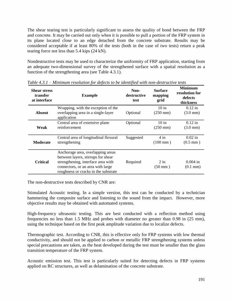
191
The shear tearing test is particularly significant to assess the quality of bond between the FRP
and concrete. It may be carried out only when it is possible to pull a portion of the FRP system in
its plane located close to an edge detached from the concrete substrate. Results may be
considered acceptable if at least 80% of the tests (both in the case of two tests) return a peak
tearing force not less than 5.4 kips (24 kN).
Nondestructive tests may be used to characterize the uniformity of FRP application, starting from
an adequate two-dimensional survey of the strengthened surface with a spatial resolution as a
function of the strengthening area (see Table 4.3.1).
Table 4.3.1 – Minimum resolution for defects to be identified with non-destructive tests
Shear stress
transfer
at interface
Example
Non-
destructive
test
Surface
mapping
grid
Minimum
resolution for
defects
thickness
Absent
Wrapping, with the exception of the
overlapping area in a single-layer
application
Optional
10 in
(250 mm)
0.12 in
(3.0 mm)
Weak
Central area of extensive plane
reinforcement
Optional 10 in
(250 mm)
0.12 in
(3.0 mm)
Moderate
Central area of longitudinal flexural
strengthening
Suggested 4 in
(100 mm )
0.02 in
(0.5 mm )
Critical
Anchorage area, overlapping areas
between layers, stirrups for shear
strengthening, interface area with
connectors, or an area with large
roughness or cracks in the substrate
Required
2 in
(50 mm )
0.004 in
(0.1 mm)
The non-destructive tests described by CNR are:
Stimulated Acoustic testing. In a simple version, this test can be conducted by a technician
hammering the composite surface and listening to the sound from the impact. However, more
objective results may be obtained with automated systems.
High-frequency ultrasonic testing. This are best conducted with a reflection method using
frequencies no less than 1.5 MHz and probes with diameter no greater than 0.98 in (25 mm),
using the technique based on the first peak amplitude variation due to localize defects.
Thermographic test. According to CNR, this is effective only for FRP systems with low thermal
conductivity, and should not be applied to carbon or metallic FRP strengthening systems unless
special precautions are taken, as the heat developed during the test must be smaller than the glass
transition temperature of the FRP system.
Acoustic emission test. This test is particularly suited for detecting defects in FRP systems
applied on RC structures, as well as delamination of the concrete substrate.

192
4.3.3.7 Summary of evaluation and acceptance
ACI and ISIS provide similar coverage of evaluation and acceptance criteria including materials
evaluation, materials/FRP system qualification tests, and field testing and sample collections.
The two codes present criteria for acceptance of fiber alignment, delamination, cure of resin,
adhesion strength, and cured thickness.
AASHTO states the contractor’s responsibilities for evaluation and acceptance. The contractor is
to submit a complete QC plan detailing inspection, sampling, testing, and criteria for acceptance.
The contractor is required to also provide detailed information on materials used as part of the
FRP system, as well as test results to verify the materials meet required design properties.
AASHTO provides a detailed list of acceptance criteria for materials and FRP system including a
description of testing required and sample sizing. AASHTO places emphasis on testing materials
under various environmental factors.
JSCE places particular emphasis on three areas; fire resistance, collision safety, and finishing
work. The code offers a reasonable coverage of the three areas but lacks coverage in areas of
evaluation and acceptance covered by other codes. TR55 does not have clear boundaries
separating aspects of quality control, inspection, and testing from evaluation and acceptance
criteria. So, items discussed in inspection overlaps evaluation and acceptance.
CNR offers a list of reference codes it recommends as basis for its materials/system
qualification. The code provides broad guidelines for evaluation and acceptance but lacks detail.
The code offers two testing categories; semi-destructive and nondestructive. Semi destructive
testing includes pull-off and shear tearing tests. Nondestructive testing includes stimulated
acoustic testing, acoustic emission testing, and thermographic testing.
A comparison of the minimum acceptable tension strength of adhesive is presented in Table
4.3.2, and a comparison of the maximum allowable area of delamination is presented in Table
4.3.3.
Table 4.3.2– Minimum acceptable tension strength of adhesive
ACI ISIS CNR
200 psi
(1.4 MPa )
220 psi
(1.5 MPa )
130-175 psi
(0.9-1.2 MPa)
Table 4.3.3 – Maximum allowable area of delamination
ACI ISIS
2 in2
(1300 mm2)
Or
5% of the total
laminate area
2.33 in2
(1500 mm2)
Or
5% of the total
laminate area

193
4.4 Maintenance and Repair
4.4.1 Introduction
Section 4 covers elements of a maintenance program with periodic inspection and testing to
identify any damage, degradation, or deficiencies to the FRP strengthening system and to make
any necessary repairs. A maintenance assessment is made from test data as well as observations,
and may include recommendations to help slow down degradation and propose necessary
repairs.
4.4.2.1 ACI
4.4.2.1.1 Inspection and assessment
ACI suggests that periodic inspection and assessment are needed to verify the long-term
performance of the FRP system. The causes of any damage or deficiencies detected during
routine inspections should be identified and addressed before performing any repairs or
maintenance.
A general inspection consists of observation for changes in color, debonding, peeling, blistering,
cracking, crazing, deflection, indications of reinforcing-bar corrosion, and other anomalies.
Other inspection methods such as ultrasonic, acoustic sounding (hammer tap), or thermographic
tests may be used to identify signs of progressive delamination.
Test data and observations are used to assess any damage and the structural integrity of the
strengthening system. Testing can include pull-off tension tests or conventional structural load
tests. The assessment can include a recommendation for repairing any deficiencies and
preventing recurrence of degradation.
4.4.2.1.2 Repair techniques
Prior to repair, the causes of the damage must first be identified and addressed. The method of
repair should depend on the cause of damage, the type of material, the form of degradation, and
the level of damage. Minor damage should be repaired, including localized FRP laminate
cracking or abrasions that affect the structural integrity of the laminate. Such damage can be
repaired by bonding FRP patches with the same FRP characteristics over the damaged area. The
FRP patches should possess the same characteristics, as thickness or ply orientation, as the
original laminate. Minor delaminations can be repaired by resin injection.
Major damage, including peeling and debonding of large areas, may require removal of the
affected area, reconditioning of the concrete, and replacement of the FRP. ACI does not mention
techniques that may be used to remove the damaged FRP. However, some recommendations for
removal are provided in Section 8.2.6.2 of this report. FRP patches should be installed in
accordance with the material manufacturer’s recommendation.

194
If the surface protective coating is to be replaced, the FRP should be inspected for structural
damage or deterioration. The surface coating should be replaced using a process approved by the
system manufacturer.
4.4.2.2 ISIS
ISIS does not address long-term maintenance, assessment and repair.
4.4.2.3 AASHTO
AASHTO recommends that the following documents be considered for evaluation and repair of
existing concrete structures and post-repair evaluation criteria:
ACI 201.1R: Guide for Making a Condition Survey of Concrete in Service
ACI 224.1R: Causes, Evaluation, and Repair of Cracks in Concrete
ACI 364.1R-94: Guide for Evaluation of Concrete Structures Prior to Rehabilitation
ACI 440.2R-08: Guide for the Design and Construction of Externally Bonded FRP Systems
for Strengthening Concrete Structures
ACI 503R: Use of Epoxy Compounds with Concrete
ACI 546R: Concrete Repair Guide
International Concrete Repair Institute (ICRI) ICRI 03730: Guide for Surface Preparation
for the Repair of Deteriorated Concrete Resulting from Reinforcing Steel Corrosion
International Concrete Repair Institute (ICRI) ICRI 03733: Guide for Selecting and
Specifying Materials for Repairs of Concrete Surfaces
NCHRP Report 609: Recommended Construction Specifications Process Control Manual for
Repair and Retrofit of Concrete Structures Using Bonded FRP Composites
AASHTO states that relevant specifications and guidelines provided by FRP manufacturers
should also be carefully reviewed.
4.4.2.4 JSCE
JSCE recommends that concrete structures strengthened with FRP should be maintained with a
systematic combination of deterioration prediction, inspection, evaluation and judgment,
countermeasures, and records.
Anticipated deterioration should be accounted for in the design and maintenance inspections by
upgrading and repairing appropriately. At the time of a maintenance event, more accurate
predictions of deterioration should be made.
4.4.2.4.1 Inspection and assessment
Inspections consist of initial, daily, periodic, detailed, and extraordinary inspections. These
should be based on the performance requirements and the predictions of performance
deterioration. Inspections should be conducted visually or using appropriate inspection
195
equipment, with consideration given to both performance requirements and the mechanism of
deterioration. Deterioration may affect the FRP material itself or the resin individually, the FRP
system as a composite material (interfacial deterioration), and deterioration of bond to the
concrete. The visual features of this deterioration may include swelling, peeling, lifting,
softening, discoloration, whitening, chalking, cracking, wearing, erosion, pinholes, scratches,
deformation, and embrittlement. However, JSCE notes that FRP sheets will block or limit the
intrusion of various external substances. As such, improved concrete durability can be
anticipated with respect to the salt attack, carbonation, freeze-thaw, alkali aggregate reaction,
chemical attacks, and fatigue. Deterioration may change various properties, including weight,
volume, mechanical properties (hardness, bond strength, tensile strength, modulus of elasticity,
elongation, etc.), and physical properties (electrical properties, thermal properties, optical
properties, etc.) Inspections using a combination of observation as well as suitable inspection
equipment should be conducted.
JSCE notes that two stages of evaluations and judgments are used: those based primarily on
visual inspections, and those based on detailed inspections. For visual inspections, a judgment is
made as to whether a detailed inspection is required. In a detailed inspection, the need for
countermeasures is evaluated and judgment is used to select the type of countermeasure.
4.4.2.4.2 Repair techniques
Countermeasures are implemented to satisfy performance requirements, based on the results of
evaluation and judgment. Countermeasures include stricter inspections, service restrictions,
repair of the FRP system, additional upgrading, improvement of appearance, and dismantling
and disposal. For minor deterioration, countermeasures should consist primarily of stricter
inspections and repair of the FRP system. The method selected should depend on the
deterioration mechanism and the extent of changes observed. However, JSCE suggests the
following for consideration. For swelling, peeling, and lifting, resin fill can be used, while for
cracking, wearing, and erosion, patching can be used. When serious deterioration or deterioration
over a wide area is observed, additional FRP upgrading should be performed. In such cases, the
existing FRP should be removed and the upgrading plan reexamined.
To implement suitable maintenance, the results of design, construction, inspection, evaluations
and judgments, repairs, additional upgrading, and so on, are to be recorded and the records
maintained. The ease of maintenance is affected by the upgrading plan and by design and
construction. More specifically, the placement of access paths to the structure that allow
inspection and monitoring equipment affects ease of maintenance. For this reason, it is
recommended to give thorough consideration to maintenance considerations in the upgrading
plan, as well as in design and construction.

196
4.4.2.5 TR55
4.4.2.5.1 Inspection and assessment
Similar to ACI, TR55 emphasizes that the FRP strengthening system should be monitored and
inspected regularly. A general inspection is recommended once a year, while a detailed
inspection is recommended once every 6 years.
A general (visual) inspection primarily consists of a surface inspection. The inspector looks for
signs of crazing, cracking, delamination, or evidence of deterioration, in addition to local damage
due to impact or surface abrasion. Signs of concrete deterioration in the form of cracking or
corrosion should also be reported. Any required identification or warning labels should be
checked for, and missing ones should be replaced.
The condition of the FRP protective layer, if any, should also be inspected. Damaged protective
coatings should be replaced in accordance with the supplier’s recommendations. It is not
appropriate to remove the protective layer to facilitate inspection.
A detailed inspection considers various items. Debonding of the FRP from the concrete may be
determined by tapping or thermography. However, TR55 reports that no nondestructive tests are
available to assess the condition of the adhesive bond. Therefore, adhesive bonding is evaluated
by puIl-off tests on the control specimens at regular intervals. PuIl-off tests should be carried out
as part of a detailed inspection, although there may be a requirement to test samples more
frequently, particularly soon after strengthening.
To facilitate inspection, instrumentation may be installed as part of the assessment process, for
example to measure strains due to live loading on the structure. Such instrumentation can be used
to indicate changes in structural response. If significant changes are observed, it is necessary to
determine whether they are due to changes in the strengthening system (such as delamination) or
due to overall changes in the concrete structure (such as additional cracking or corrosion) so that
appropriate action can be taken. The Health and Safety File for the structure should include
details of any instrumentation that was installed as part of the strengthening exercise, along with
any data obtained before and after strengthening.
Information on the materials used in strengthening should be included in the Health and Safety
File for the structure. This File should also include reported minor areas of delamination and any
initial faults detected in the strengthening system; identification of critical strengthening regions
such as anchorage zones and high stress regions; and procedures prepared by the engineer on
actions to be taken for various forms of damage to the FRP strengthening system, which should
be tailored to each particular structure.
In order to facilitate the testing and evaluation of the FRP strengthening system, it is
recommended that additional areas of the strengthened structure, away from the regions that
were strengthened, are also bonded with the FRP system for future testing that does not impact
the system performance. TR55 reports that this approach has been adopted on a number of

197
structures including the Barnes Bridge in Manchester and the John Hart Bridge in British
Columbia.
Alternatively, FRP can be bonded to concrete samples which can be stored near the structure.
Samples can be inspected and tested as part of the inspection regime. To aid inspection, some or
all of the samples should not be covered with any protective layer. They should thus indicate a
lower bound of performance of the composites bonded to the structure. Details should be
included in the structure’s Health and Safety File along with recommendations for the frequency
of testing.
4.4.2.5.2 Repair techniques
For localized damage to the FRP, repairs can be made with resin injection or plate overlapping.
For major damage, such as peeling and debonding of large areas, the defective material should
be removed to an extent that material on the periphery of the repair is fully bonded. The
concrete surface should then be prepared, and an FRP patch installed that allows adequate
overlap between the new and old materials. The compatibility of the proposed repair material
with the materials already in place should be checked. The repair material must have similar
characteristics to the material in place such as fiber orientation, volume fraction, strength,
stiffness and overall thickness.
4.4.2.6 CNR
CNR recommends that, due to the poor availability of data regarding long term behavior of FRP
systems used for strengthening, appropriate monitoring of the installed FRP system should be
performed with periodic semi- and non-destructive tests The aim of the monitoring process is to
identify potential problems with the temperature of the installed FRP system; environmental
humidity; displacements and deformations of the strengthened structure; fiber damage; and
defects or delaminations in the installed FRP system.
4.4.2.7 Summary of maintenance and repair
ACI, TR55 and JSCE all present a relatively broad and reasonable coverage of maintenance and
repair issues. They each call for development and implementation of a periodic maintenance
program including visual inspection, specified testing, an assessment of damage to evaluate the
structural integrity of the system, and recommendations for repair. Based on the type and
severity of damage, the three codes offer suggestions for appropriate repair methods. CNR's
coverage on maintenance and repair is brief, and states the need for periodic monitoring and
inspection using semi and non-destructive tests for assessment of the system. No discussion of
repair recommendation is presented. ISIS does not cover this topic, while AASHTO does not
provide detailed coverage, but refers to a list of specialized documents from ACI, ICRI, and
NCHRP for further suggestions.

198
CHAPTER 5: LABORATORY TESTING
5.1 Durability Testing Overview
5.1.1 Introduction
The purpose of the laboratory testing is to assess FRP system degradation when exposed to the
climate of Michigan and to develop a corresponding environmental reduction factor. To achieve
this, two primary groups of FRP-strengthened concrete samples were prepared. Group 1 samples
concern material and bond degradation assessment and are used to generate the primary data for
environmental response by way of pull-off testing. Group 2 specimens are used as ‘spot checks’
to verify the applicability of the material-level response results to structural-level degradation
with respect to failure modes such as flexure, shear, and axial compression.
Group 1 consists of two identical sets of FRP-strengthened concrete test samples. One set is kept
outdoors, bearing full exposure to natural weathering effects including exposure to the sun and
variation in moisture and temperature levels. The second set undergoes acceleration testing in an
environmental chamber using a predetermined environmental acceleration cycle. Pull-off
adhesive bond testing is conducted on samples from Group 1 sets one and two at appropriate
testing frequencies, as discussed below. A calibration of bond degradation between set one and
set two makes it possible to establish acceleration factors that are appropriate for the specific
climate in Michigan.
Group 2 samples include sample beams for flexural, 2-sided shear, and u-wrap (3-sided shear)
tests, and wrapped cylinder samples for confinement testing. Fabric as well as FRP plates were
used for flexural strengthening. A selection of the samples (flexural and shear-strengthened)
were kept outdoors for environmental weathering while identical samples were reserved for
accelerated testing.
Concrete samples used for the Group 2 beam specimens have dimensions of 16” x 4.3” x 4.1”
(length x width x height). These dimensions are based on the work of Elarbi (2011) and are in
accordance with ASTM C293-08. Cylindrical samples are standard 4” x 8” (diameter x height)
size compressive strength cylinders in accordance with ASTM C39-08. Group 1 pull-off test
samples are sized to be approximately half the width of the Group 2 beam samples. These
dimensions are 16” x 2.0” x 4.1”. Note that multiple pull-off tests can be conducted on a single
Group 1 test specimen.
5.1.2 Materials procurement
Concrete was acquired from a commercial batch plant (McCoig Materials – MDOT plant No. M-
11) with experience and knowledge of MDOT concrete mix designs for bridge applications.
Several suppliers of FRP were used for strengthening. In particular, Sika, Fyfe, and BASF
provided material for CFRP wraps, epoxy adhesives, and protective coating materials. The fabric
wraps were primarily unidirectional CFRP, although bi-directional wraps from Sika and Fyfe
were also used. In addition, CFRP plates from Sika and Fyfe as well as protective coatings (FRP

199
paint) were obtained for testing. Section 5.2 presents the manufacturer-specified material
properties of the FRP systems.
5.1.3 Testing program
FRP-strengthened samples were prepared with several variations for testing, using:
Unidirectional and bi-directional fabrics
Specimens to evaluate bond (Group 1) as well as to check structural-level behavior (Group 2)
Different types of epoxy
Different fabric characteristics
Specimens with and without a protective coating
CFRP plates as an alternative to fabric
A total of 127 concrete samples were strengthened. Thirteen representative samples were placed
outdoors under the exposure of natural weathering, with identical samples reserved for
accelerated testing indoors.
5.2 Materials Properties
5.2.1 Concrete sample preparation and properties
As noted above, a concrete sample size of 16” x 4.3” x 4.1” was selected for Group 2 structural
testing (shear and flexure) in accordance with ASTM 293-08, while the adhesive bond pull-off
test samples (Group 1) were half-width (2.0” wide). For casting, plywood mold assemblies were
prepared (Figure 5.2.1) and a standard MDOT 2012 Grade D concrete mix was ordered from
McCoig Materials. Pour dates were February 1 and April 5, 2013 (Figure 5.2.2). Fresh concrete
properties were determined on-site with standard ASTM tests (Figure 5.2.3).
Figure 5.2.1 – Typical plywood mold assembly

200
Figure 5.2.2 – Fresh concrete surface finishing
Figure 5.2.3 – Fresh concrete onsite testing
Concrete properties were as follows:
Coarse aggregate (L6AA-OTT) 1720 lbs.
Fine aggregate (2NS-AAR) 1240 lbs.
Cement (Type 1) 658 lbs.
Water 41.6 gallons
W/C ratio 0.4
Slump 5.0 in
Air content 6%

201
Test cylinders with 4” diameter formed at the time of casting were moist-cured by submersion in
a water bath along with the cast specimens and later tested for evaluation of compressive
strength using an MTS-290 testing machine. The specified 28 day compressive strength of the
mix was 5,500 psi. Table 5.2.1 provides the average compressive strength of the cylinder tests at
different times. A minimum of three cylinders were used for each set. The target compressive
strength of 5500 psi was exceeded at 26 day sample testing.
Table 5.2.1 - Concrete compressive test results
Set No. Age at
testing, days
Mean
strength, lbs.
Mean
Compressive
Strength, psi
1 5 33712 2683
2 7 48080 3826
3 10 60160 4787
4 26 72131 5740
5.2.2 FRP material properties
As noted above, FRP strengthening systems with carbon fiber and epoxy adhesives were
obtained from Sika, Fyfe, and BASF. Epoxies consisted of resins and hardeners. In the following
sections, products and their physical and mechanical properties are presented.
5.2.2.1 Sika material properties
FRP wraps from Sika include Sikawrap Hex 113C bi-directional, Sikawrap Hex 103C, Sikawrap
Hex 230C, and Sika carboDur S1014 plate (4” wide strip). Table 5.2.2 presents Sika fiber
properties, while Tables 2.3 and 2.4 provide the physical and mechanical properties of Sika
laminate. Sika epoxies are used as part of the FRP strengthening system to achieve the bond
between FRP wrap and the concrete substrate. Three types of epoxies are included; SikaDur 300,
SikaDur 330, and SikaDur 30. SikaDur 300 and SikaDur 330 are suitable for wet lay-up
applications of FRP wrap with SikaDur 300 having the lower viscosity of the two. SikaDur 30 is
designed to work with FRP plates. Table 5.2.5 presents the mechanical properties of SikaDur
300 and SikaDur 330. Table 5.2.6 presents the mechanical properties of SikaDur 30.
Table 5.2.2 - Sika fiber properties
Fiber
Properties Unit
Sikawrap
Hex 103C
Sikawrap
Hex 113C
Sikawrap
Hex 230C
Tensile
Strength
psi 550,000 66,000 500,000
MPa 3,793 456 3,450
Tensile
Modulus
psi 33,000,000 6,000,000 33,400,000
GPa 228,000 41,400 230,000
Ultimate
Elongation % 1.50 1.20 1.50
Density lbs/in
3 0.065 0.065 0.065
g/cc 1.8 1.8 1.8

202
Table 5.2.3 – Physical properties of Sika laminate
Laminate
Physical
Properties
Unit Sikawrap
Hex 103C
Sikawrap
Hex 113C
Sikawrap
Hex 230C
Fiber type
Carbon Carbon Carbon
Color
Black Black Black
Weight
OZ/Y2 18 5.7 6.7
g/m2 618 196 230
No. of
Filaments 24,000
Ply Thickness in 0.04 0.01 0.015
mm 1.016 0.25 0.381
Table 5.2.4 - Mechanical properties of Sika laminate
Cured Laminate
Mechanical
Properties
Sikawrap
Hex 103C
Sikawrap
Hex 230C
Unit Test Design Test Design
Tensile Strength psi 123,000 104,000 129,800 104,000
MPa 849 717 894 715
Tensile Modulus psi 10,239,800 9,446,600 9,492,300 8,855,000
MPa 70,552 65,087 65,402 61,012
Tensile
Elongation % 1.12 0.98 1.33 1.09
140 deg. Tensile
Strength
psi 123,000 101,400 118,200 102,000
MPa 847 699 814 703
140 deg. Tensile
Modulus
psi 10,136,900 9,156,500 9,789,000 8,693,000
MPa 69,843 63,088 67,450 59,896
140 deg. Tensile
Elongation % 1.13 0.97 1.16 1.00
Comp. Strength psi 113,000 103,800 113,000 97,000
MPa 779 715 779 668
Comp. Modulus psi 9,726,000 8,930,600 9,724,700 9,230,000
MPa 67,014 61,532 67,003 63,597
90 deg. Tensile
Strength
psi 3,500 2,300 3,965 390
MPa 24 16 27 23
90 deg. Tensile
Modulus
psi 705,500 576,700 852,800 799,000
MPa 4,861 3,973 5,876 5,502
90 deg. Tensile
Elongation % 0.45 0.33 0.46 0.4

203
Table 5.2.4 - Mechanical properties of Sika laminate, Cont. Cured Laminate
Mechanical
Properties
Sikawrap
Hex 103C
Sikawrap
Hex 230C
Unit Test Design Test Design
In-plane Shear
Strength
psi 7,500 6,700 9,100 8,100
MPa 52 46 63 56
In-plane Shear
Modulus
psi 362,500 347,500 421,200 406,000
MPa 2,498 2,394 2,902 2,800
Tensile Strength
per inch width
lbs 4,928 4,160 1,947 1,560
kN 21.9 18.5 8.7 6.9
Table 5.2.5 - SikaDur 300 and SikaDur Hex 330 properties
Epoxy
Properties Unit
Sikadur Hex
330(2) Sikadur 300(1)
Tensile
Strength
psi 4,900 8,000
MPa 33.8 55
Tensile
Modulus
psi
250,000
MPa
1,724
Tensile
Elongation % 1.2 3
Flexural
Strength
psi 8,800 11,500
MPa 60.6 79
Flexural
Modulus
psi 506,000 500,000
MPa 3,489 3,450
1. Material properties after 14 day cure
2. Material properties after 7 day cure
Table 5.2.6 - SikaDur 30 properties
Epoxy Properties Unit Sikadur 30
Tensile strength after 7 days psi 3600
MPa 24.8
Modulus of elasticity after 7 days psi 65,000,000
MPa 4,482
Flexural strength psi 6,800
MPa 46.8
Shear strength after 14 days psi 3,600
MPa 24.8
Elongation at break % 1

204
5.2.2.2 Fyfe material properties
FRP wraps obtained from Fyfe include Tyfo SCH-41, Tyfo SCH-41-.5X, and Tyfo SCH-41H.
Table 5.2.7 provides the mechanical properties of Fyfe fiber wraps. Tables 5.2.8 and 5.2.9
provide the physical and mechanical properties of Fyfe laminate. Tyfo S epoxy is the main
adhesive used in the Fyfe FRP system. Tyfo SW is a variation of Tyfo S formulated for
underwater applications. Table 5.2.10 provides the properties of Tyfo S epoxy.
Table 5.2.7 - Fyfe fiber material properties
Fiber
Properties Unit
Tyfo
SCH-41
Tyfo
SCH-41- .5X
Tyfo
SCH-41H
Tensile
Strength
psi 550,000 550,000 675,000
MPa 3,790 3,790 4,650
Tensile
Modulus
psi 33,400,000 33,400,000 42,000,000
GPa 230,000 230,000 289,600
Ultimate
Elongation % 1.70 1.70 1.70
Density lbs/in.
3 0.063 0.063 0.065
g/cc 1.74 1.74 1.8
Table 5.2.8 - Physical properties of Fyfe laminate
Laminate
Physical
Properties
Unit
Tyfo
SCH-41
Tyfo
SCH-41- .5X
Tyfo
SCH-41H
Fiber type Carbon Carbon Carbon
Color Black Black Black
Weight OZ/Y
2 19 9.5 24
g/m2 644 322 814
Ply Thickness in 0.04 0.024 0.04
mm 1.0 0.6 1.0

205
Table 5.2.9 - Mechanical properties of Fyfe laminate
Cured
Laminate
Mechanical
Properties
Unit
Tyfo
SCH-41
Tyfo
SCH-41- .5X
Tyfo
SCH-41H
Test Design Test Design Test Design
Tensile
Strength
psi 143,000 121,000 137,000 116,000 200,000 170,000
MPa 986 834 944.6 799.8 1,380 1,170
Tensile
Modulus
psi 13,900,000 11,900,000 14,500,000 12,300,000 15,500,000 13,100,000
MPa 95,800 82,000 99,900 84,800 106,800 90,300
Tensile
Elongation % 1.00 0.85 0.95 0.80 1.30 1.10
Flexural
Strength
psi 17,900 15,200
MPa 123.4 104.8
Flexural
Modulus
psi 452,000 384,200
MPa 3,120 2,650
Flexural
Failure
Strain
% 1.00 0.85
Comp.
Strength
psi 50,000 42,500
MPa 344.8 293
Comp.
Modulus
psi 11,200,000 9,500,000
MPa 77,200 65,500
Tensile
Strength per
inch width
lbs 5,720 4,840 3,288 2,784 8,000 6,800
kN 25.4 21.5 14.6 12.4 35.6 30.2
Table 5.2.10 - Fyfe epoxy properties
Epoxy
properties Unit
Tyfo S
Epoxy
Tensile Strength psi 10,500
MPa 72.4
Tensile Modulus psi 461,000
MPa 3,180
Tensile
Elongation % 5
Flexural
Strength
psi 17,900
MPa 123.4
Flexural
Modulus
psi 452,000
MPa 3,120

206
5.2.2.3 BASF materials properties
The FRP strengthening system obtained from BASF includes a set of products with the
commercial name MBrace. One type CFRP wrap (MBrace CF130) was available. The MBrace
surface treatment and epoxy adhesive products obtained were:
MBrace putty for plugging holes and leveling depressions on the concrete surface.
MBrace primer to enhance the adhesive bond between the saturant and concrete
substrate.
MBrace saturant resin to saturate the wrap and achieve adhesive bond to primer and other
plies.
Tables 5.2.11, 5.2.12, 5.2.13 and 5.2.14 provide material properties of MBrace CF130, MBrace
primer, saturant, and putty, respectively.
Table 5.2.11 - Material properties of MBrace CF130
Table 5.2.12 - Material properties of MBrace primer
Fiber
properties Unit
Tensile
properties
Compressive
properties
Flexural
Properties
Yield strength psi 2100 3800 3500
MPa 14.5 26.2 24.1
Elastic
modulus
psi 105 97 86.3
MPa 717 670 595
Rupture strain % 40 10 Large deformation
with no rupture
Ultimate
strength
psi 2500 4100 3500
MPa 17.2 28.3 24.1
Fiber Properties Unit MBrace
CF130
Tensile Strength psi 550,000
MPa 3,800
Tensile Modulus psi 33,000,000
GPa 227,000
Ult. Elongation % 1.67
Nominal thickness in/ply 0.0065
mm/ply 0.165
Ultimate tensile strength
per unit width
Kips/in/ply 3.57
KN/mm/ply 0.625
Tensile modulus per unit
width
Kips/in/ply 215
KN/mm/ply 38

207
Table 5.2.13 - Material properties of MBrace saturant
Material
properties Unit
Tensile
properties
Compressive
properties
Flexural
Properties
Yield
strength
psi 7900 12500 20000
MPa 54 86.2 138
Elastic
modulus
psi 440000 380000 540000
MPa 3034 2620 3724
Rupture
strain %
3.5
5
5
Ultimate
strength
psi 8000 12500 20000
MPa 55.2 86.2 138
Table 5.2.14 – Material properties of MBrace putty
Fiber
properties Unit
Tensile
properties
Compressive
properties
Flexural
Properties
Yield
strength
psi 1800 3300 3800
MPa 12 22.8 26.2
Elastic
modulus
psi 260000 155000 130000
MPa 1800 1076 895
Rupture
strain % 7 10 7
Ultimate
strength
psi 2200 3300 4000
MPa 15.2 22.8 27.6
5.2.3 Sample preparation for FRP strengthening
At the conclusion of concrete sample curing, the samples were allowed to dry for 48 hours prior
to surface preparation. The procedure includes the following steps:
Surface grinding with an angle grinder to remove any weak surface concrete and remove all
impurities.
Grinding to round edges for U-wrap samples.
Wire brushing of the surface to reach depressed areas and surface imperfections.
Surface filling with putty of large defects to ensure a level surface.
Air pressure cleaning to remove dust prior to FRP application.

208
Figure 5.2.4 – Surface grinding of concrete samples
5.2.4 Application of FRP to concrete samples
Manufacturer guidelines were followed closely during FRP installation, including use of
appropriate procedures, tools, and safety requirements. Representatives from Sika and BASF
supervised the installation to ensure adherence to guidelines. Figures 5.2.5 and 5.2.6 show the
installation of the FRP and the completed samples. Based on this experience, two observations
are as follows:
It was difficult to fully saturate FRP fabric with high viscosity resin. If this combination of
strengthening materials are used for wall and/or slab applications, special care is
recommended to ensure that the fabric is fully saturated. The higher viscosity resins are
recommended for FRP sheet (laminates) applications rather than fabrics.
Strict adherence to the epoxy pot life and operating temperature range during the FRP
strengthening is necessary to avoid impacting the quality of installation. Correspondingly,
advanced planning of installation procedures is crucial to a successful installation. Careful
adherence to the manufacturer’s recommended guidelines is critical to avoid an early set of
the epoxy.
These recommendations are noted in Chapter 8 (sections 8.2.3.6 and 8.2.3.7).

209
Figure 5.2.5 – FRP installation using Fyfe FRP system
Figure 5.2.6 – Installed FRP system

210
5.3 Test Plan and Procedures
5.3.1 Summary of test specimens
A summary of all specimen characteristics is presented in Table 5.3.1 for flexure beam samples,
Table 5.3.2 for shear beam samples, Table 5.3.3 for confinement cylinders, and Table 5.3.4 for
pull-off test samples. Table 5.3.5 summarizes the number of each type of sample, while Figures
5.3.1-5.3.7 show select samples for different testing purposes.
Table 5.3.1 – FRP strengthened samples for flexural structural testing
Epoxy Wrap Uni/
Bi
No. of
Samples
sample
designation
sample
cast date
Sample
Wrapping
date
Indoor/
Outdoor
Outdoor
Samples
Paint
Y/N
sample
size
Sika
SikaDur
300
103C U 3 19, 20, 21 03/29/13 05/16/13 I N N 4"x4"x16"
230C U 3 22, 23, 24 03/29/13 05/16/13 I N N 4"x4"x16"
SikaDur
330
103C U 3 1, 2, 3 02/01/13 03/07/13 I N N 4"x4"x16"
230C U 3 7, 8, 9 02/01/13 03/07/13 I N N 4"x4"x16"
113C B 3 4, 5, 6 02/01/13 03/07/13 I N N 4"x4"x16"
SikaDur
30 4" Strip U 3 47, 48, 49 02/01/13 03/07/13 I N N 4"x4"x16"
Fyfe
Tyfo S
SCH-41 U 4
50, 51, 52,
53 03/29/13 05/15/13 I N y 4"x4"x16"
SCH-41 U 2 54, 55 03/29/13 05/15/13 O 54, 55 y 4"x4"x16"
SCH-41
H U 3 56, 57, 58 03/29/13 05/15/13 I N N 4"x4"x16"
BCC B 3 59, 60, 61 03/29/13 05/15/13 I N N 4"x4"x16"
Tyfo SW SCH-41 U 3 62, 63, 64 03/29/13 05/15/13 I N N 4"x4"x16"
SCH-41-
0.5X U 3 65, 66, 67 03/29/13 05/15/13 I N N 4"x4"x16"
MB-3 SCH-41 U 2 68, 69 03/29/13 05/15/13 I N N 4"x4"x16"
SCH-41-
0.5X U 3 70, 71, 72 03/29/13 05/15/13 I N N 4"x4"x16"
BASF
Mbrace
Primer/
Saturant
Mbrace
CF130
U 3 98, 99, 100 03/29/13 05/16/13 O
98, 99,
100 y 4"x4"x16"
U 2 101, 102 03/29/13 05/16/13 I N y 4"x4"x16"
U 2 103, 104 03/29/13 05/16/13 I N y 4"x4"x16"
U 2 105, 106 03/29/13 05/16/13 I N Y 4"x4"x16"
Mbrace
Primer/
Concresive
Mbrace
S&P Laminate
U 3 107, 108,
109 03/29/13 05/16/13 I N N 4"x4"x16"

211
Table 5.3.2 – FRP strengthened samples for shear structural testing
Epoxy Wrap Uni/
Bi
No. of
Samples
sample
designation
sample
cast date
Sample
Wrapping
date
Indoor/
Outdoor
Outdoor
Samples
Apply
paint
Y/N
Shear
Type
SIKA
SikaDur
300
103C U 3 25, 26, 27 03/29/13 05/16/13 I N N 2-sided
113C B 3 28, 29, 30 03/29/13 05/16/13 I N N 2-sided
SikaDur
330
103C U 3 10, 11, 12 02/01/13 03/07/13 I N N 2-sided
113C B 3 13, 14, 15 02/01/13 03/07/13 I N N 2-sided
SikaDur
300
113C B 3 31, 32, 33 03/29/13 05/16/13 I N N U-wrap
230C U 2 42, 43 03/29/13 05/16/13 I N N U-wrap
SikaDur
330 113C B 3 16, 17, 18 02/01/13 03/07/13 I N N U-wrap
FYFE
Tyfo S SCH-41 U 3 73, 74, 75 03/29/13 05/15/13 I N N 2-sided
BCC B 3 76, 77, 78 03/29/13 05/15/13 I N N 2-sided
MB-3 SCH-41 U 2 79, 80 03/29/13 05/15/13 I N N 2-sided
Tyfo S SCH-41 U 3 81, 82, 83 03/29/13 05/15/13 I N N U-wrap
BASF
Mbrace
Primer/
Saturant
Mbrace
CF130
U 2 110, 111 03/29/13 05/16/13 O 110, 111 y 2-sided
U 2 112, 113 03/29/13 05/16/13 I N y 2-sided
U 2 114, 115 03/29/13 05/16/13 I N y 2-sided
U 3
116, 117,
118 03/29/13 05/16/13 I N y U-wrap
Table 5.3.3 – FRP strengthened samples for confinement structural testing
Epoxy Wrap Uni/
Bi
No. of
Samples
sample
designation
sample
cast date
Sample
Wrapping
date
Indoor/
Outdoor
Outdoor
Samples
Apply
paint
Y/N
Sample
Type
SIKA
SikaDur
300 103C U 3 44, 45, 46 03/29/13 05/16/13 I N N
4"x8"
Cyl.
FYFE
Tyfo S SCH-41 U 3 92, 93, 94 03/29/13 05/15/13 I N N
4"x8"
Cyl.
Tyfo SW
SCH-41-
0.5X U 3 95, 96, 97 03/29/13 05/15/13 I N N
4"x8"
Cyl.
BASF
Mbrace
Primer/
Saturant
Mbrace CF 130
U 3 119, 120,
121 03/29/13 05/16/13 I N N
4"x8" Cyl.

212
Table 5.3.4 – FRP strengthened samples for pull-off adhesion testing
Epoxy Wrap Uni/
Bi
No. of
Samples
sample
designation
sample
cast date
Sample
Wrapping
date
Indoor/
Outdoor
Outdoor
Samples
Apply
paint
Y/N
Type
SIKA
SikaDur
300
103C U 2 34, 35 03/29/13 05/16/13 I/O 34
1/2
both
samples
4"x2"x16"
113C B 2 36, 37 03/29/13 05/16/13 I 1 N 4"x2"x16"
SikaDur
330
103C U 2 38, 39 02/01/13 03/07/13 I/O 38 1/2 both
samples
4"x2"x16"
113C B 2 40, 41 02/01/13 03/07/13 I 1 N 4"x2"x16"
FYFE
Tyfo S
SCH-
41 U 2 84, 85 03/29/13 05/15/13 I/O 84
1/2
both samples
4"x2"x16"
BCC B 2 86, 87 03/29/13 05/15/13 I N N 4"x2"x16"
Tyfo SW SCH-
41 U 2 88, 89 03/29/13 05/15/13 I/O 88
1/2
both samples
4"x2"x16"
MB-3 SCH-
41 U 2 90, 91 03/29/13 05/15/13 I N N 4"x2"x16"
BASF
Mbrace
Primer/
Saturant
Mbrace
CF 130
U 3 122, 123,
124 03/29/13 05/16/13 I/O 122 Y
4"x8" Cyl.
U 3 125, 126,
127 03/29/13 05/16/13 I/O 125 N
4"x8"
Cyl.
Table 5.3.5 – FRP strengthened samples for pull-off adhesion testing
Strengthening type Sample type Strengthened
side/s
No. of
Samples
Flexural beam bottom 53
Shear beam 2 sides 26
Flexural/Shear beam 3 sides 14
Pull-off Test ½-thickness
beam 1 side 22
Confinement cylinder around 12
TOTAL 127

213
Figure 5.3.1 – FRP strengthened samples for flexure using FRP wrap (fabric)
Figure 5.3.2 – FRP strengthened samples for flexure using FRP plates (sheets)

214
Figure 5.3.3 – FRP strengthened samples for 2-sided shear
Figure 5.3.4 – FRP strengthened samples using U-wrap
Figure 5.3.5 – Pull-off test samples using FRP wrap

215
Figure 5.3.6 – FRP strengthened confinement samples
Figure 5.3.7 – Outdoor samples exposed to natural weathering
5.3.2 Test plan
As noted earlier in this Chapter, for each outdoor sample set, an identical set is kept for
accelerated testing and a control set is kept indoors at room temperature. Pull-off testing on
outdoor samples, identical samples exposed to accelerated testing, and control samples at
appropriate time intervals help quantify the acceleration factor. Once established, the
acceleration factor can be used to estimate performance loss without the need for time-intensive
outdoor weathering tests.
Outdoor samples were tested at 9 months and 14 months. Additional samples have been saved
for future testing to refine the acceleration factors. Accelerated samples are conditioned in a

216
Tenney T10RC-1.5 SPL environmental chamber (Figure 5.3.8) in programmed runs. Each run
consists of 60 designed cycles followed by pull-off testing of (see Figure 5.3.9 for a single
accelerated testing cycle). As conditioning progressed, accelerated test samples were tested at
60, 120, 180, and 240 cycles for half-painted samples. These samples have been saved for
additional weathering and future pull-off testing to further refine the results as needed. Tables
5.3.6 and 5.3.7 present the testing schedule for accelerated and outdoors test samples.
Figure 5.3.8 – Tenney environmental chamber
Figure 5.3.9 – Accelerated testing cycle detail
15 min 75 min 80 min 75 min 15 min
75 F
158 F FFF
-4 F
75 F FFFF
C
260 min = 4 1/3 hours
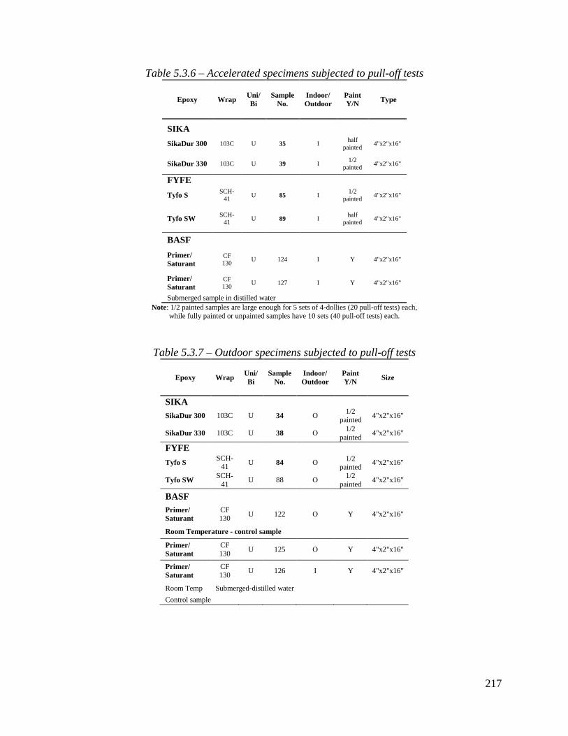
217
Table 5.3.6 – Accelerated specimens subjected to pull-off tests
Epoxy Wrap Uni/
Bi
Sample
No.
Indoor/
Outdoor
Paint
Y/N Type
SIKA
SikaDur 300 103C U 35 I half
painted 4"x2"x16"
SikaDur 330 103C U 39 I 1/2
painted 4"x2"x16"
FYFE
Tyfo S SCH-
41 U 85 I
1/2
painted 4"x2"x16"
Tyfo SW SCH-
41 U 89 I
half
painted 4"x2"x16"
BASF
Primer/
Saturant
CF
130 U 124 I Y 4"x2"x16"
Primer/
Saturant
CF
130 U 127 I Y 4"x2"x16"
Submerged sample in distilled water
Note: 1/2 painted samples are large enough for 5 sets of 4-dollies (20 pull-off tests) each,
while fully painted or unpainted samples have 10 sets (40 pull-off tests) each.
Table 5.3.7 – Outdoor specimens subjected to pull-off tests
Epoxy Wrap Uni/
Bi
Sample
No.
Indoor/
Outdoor
Paint
Y/N Size
SIKA
SikaDur 300 103C U 34 O 1/2
painted 4"x2"x16"
SikaDur 330 103C U 38 O 1/2
painted 4"x2"x16"
FYFE
Tyfo S SCH-
41 U 84 O
1/2 painted
4"x2"x16"
Tyfo SW SCH-
41 U 88 O
1/2
painted 4"x2"x16"
BASF
Primer/
Saturant
CF 130
U 122 O Y 4"x2"x16"
Room Temperature - control sample
Primer/
Saturant
CF
130 U 125 O Y 4"x2"x16"
Primer/
Saturant
CF
130 U 126 I Y 4"x2"x16"
Room Temp Submerged-distilled water
Control sample

218
5.3.3 Pull-off testing
Pull-off adhesion testing is accomplished using a DeFelsko PosiTest AT-A automatic adhesion
tester (Figure 5.3.10). The test is conducted in accordance with ASTM D4541-09 Standard test
method for pull-off strength of coatings using portable adhesion testers. The test involves several
steps:
Step 1 – Dolly and surface preparation
Contaminants are removed from the dolly attachment surface and the sample surface using
abrasive pads. Residue left from the abrading process is then removed using a dry cloth or paper
towel. The area is then degreased with acetone or alcohol.
Step 2 – Adhesive and dolly application
Epoxi-Patch adhesive (Loctite 907- Hysol) is applied uniformly on the base of the dolly, then the
dolly is attached to the sample surface. The dolly is pressured in place and excess adhesive is
removed from around the dolly.
Step 3 – Test area separation after full curing of adhesive
A coring tool that fits the outside of the dolly is used to cut the FRP and just reach the concrete
substrate. This helps to obtain a true measure of adhesion not affected by the surrounding fibers.
Step 4 – Pull-off test
The test is performed according to the PosiTest instructions using hydraulic pressure to separate
the dolly from the sample surface. The tensile strength value is displayed on a digital screen and
results may be saved to computer though a USB port.
A 20 mm diameter dolly size was used along with a coring bit with a 23 mm outside diameter for
dolly separation in Step 3. A table-top drill press is used to achieve dolly separation prior to pull-
off testing. Figure 5.3.11 shows two sets of pull-off dollies installed on sample no. 85. Figure
5.3.12 shows pull-off testing in progress.
Figure 5.3.10 – Pull-off adhesion tester (DeFelsko)

219
Figure 5.3.11 – Installation of dollies on a half-painted sample
Figure 5.3.12 – Pull-off adhesion testing underway
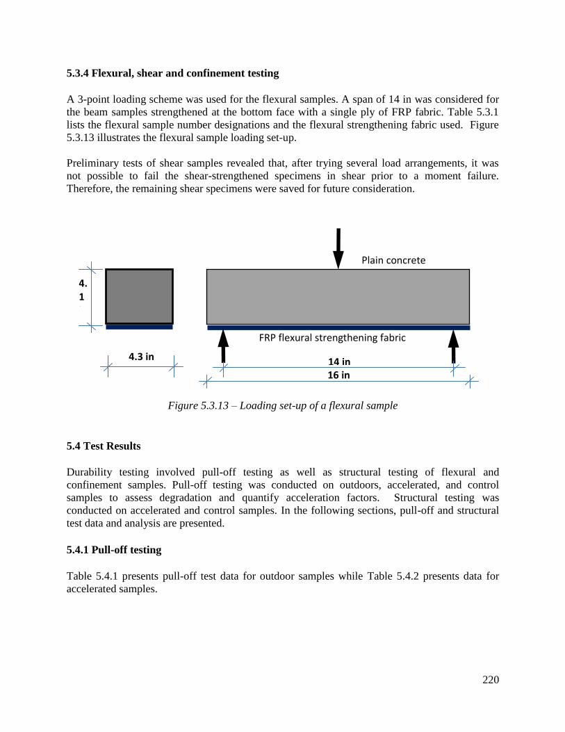
220
5.3.4 Flexural, shear and confinement testing
A 3-point loading scheme was used for the flexural samples. A span of 14 in was considered for
the beam samples strengthened at the bottom face with a single ply of FRP fabric. Table 5.3.1
lists the flexural sample number designations and the flexural strengthening fabric used. Figure
5.3.13 illustrates the flexural sample loading set-up.
Preliminary tests of shear samples revealed that, after trying several load arrangements, it was
not possible to fail the shear-strengthened specimens in shear prior to a moment failure.
Therefore, the remaining shear specimens were saved for future consideration.
Figure 5.3.13 – Loading set-up of a flexural sample
5.4 Test Results
Durability testing involved pull-off testing as well as structural testing of flexural and
confinement samples. Pull-off testing was conducted on outdoors, accelerated, and control
samples to assess degradation and quantify acceleration factors. Structural testing was
conducted on accelerated and control samples. In the following sections, pull-off and structural
test data and analysis are presented.
5.4.1 Pull-off testing
Table 5.4.1 presents pull-off test data for outdoor samples while Table 5.4.2 presents data for
accelerated samples.
14 in
16 in
4.3 in
4.1 in
FRP flexural strengthening fabric
Plain concrete beam

221
Table 5.4.1 – Results of completed pull-off testing of outdoor samples
Sample
Number Epoxy Wrap
Paint
Y/N
control
pull off
test
results,
psi
Type of
failure
9-month
Pull off
test result,
psi
Type of
failure
14-month
Pull off
test result,
psi
Type of
failure
34 SikaDur
300 103C
Y
1014 concrete 802 concrete 833 concrete
424 concrete 929 concrete 645 concrete
950 concrete 861 concrete 749 concrete
930 concrete 693 concrete
N
1014 concrete 571 Adhesive 856 concrete
424 concrete 835 concrete 795 FRP
950 concrete 695 concrete 576 FRP
930 concrete 850 concrete
38 SikaDur
330 103C
Y
552 concrete 636 concrete
729 concrete 807 concrete
724 concrete 686 concrete
724 concrete 854 concrete
N
715 concrete 755 concrete 647 concrete/
FRP
740 concrete 566 concrete 787 concrete/
FRP
614 concrete 625 FRP 718 concrete
932 concrete 542 concrete

222
Table 5.4.1 – Results of completed pull-off testing of outdoor samples, Cont.
Sample
Number Epoxy Wrap
Paint
Y/N
control
pull off
test
results, psi
Type of
failure
9-month
Pull off
test
result, psi
Type of
failure
14-month
Pull off
test
result,
psi
Type of
failure
84 Tyfo S SCH-
41
Y
828 concrete 833 concrete
1083 concrete 645 concrete
875 concrete 749 concrete
693 concrete
N
720 concrete 995 concrete 404 FRP
619 concrete 1028 concrete 652 concrete
530 concrete 779 concrete 609 FRP
659 concrete 613 FRP
88 Tyfo SW SCH-
41
Y
487 concrete/
FRP 487
concrete/F
RP
201
concrete/
FRP 201
concrete/F
RP
712
concrete/
FRP 712
concrete/
FRP
N
581 Adhesive 408 concrete/
FRP 408
concrete/
FRP
387 Adhesive 284 concrete/
FRP 284
concrete/
FRP
397 Adhesive 178 concrete/
FRP 178
concrete/
FRP
339 concrete/
FRP
1015 concrete 704 concrete 888 concrete
122 Primer/
Saturant CF130 Y 1078 concrete 748 concrete 899 concrete
867 concrete 741 concrete 497 concrete
1135 concrete 1161 concrete
1183 concrete
1015 concrete 578 concrete 591 concrete
125 Primer/
Saturant CF130 Y 1078 concrete 556 concrete 933 concrete
867 concrete 622 concrete 900 concrete
1135 concrete 993 concrete
1183 concrete
1015 concrete 834 concrete 887 concrete
126 Primer/
Saturant CF130 Y 1078 concrete 638 concrete 979 concrete
867 concrete 898 concrete 572 concrete
Submerged -control -
INDOOR 1135 concrete 1135 946 concrete
1183 concrete 1183

223
Table 5.4.2 – Results of completed pull-off testing of accelerated samples
Sample
No. Epoxy Wrap
Paint
Y/N
60
cycles,
psi
Failure
Mode
120
cycles,
psi
Failure
Mode
180
cycles,
psi
Failure
Mode
240
cycles,
psi
Failure Mode
35 SikaDur
300 103C
Y
674 concrete 551 concrete/FRP 925 concrete/FRP 398 concrete
396 concrete 656 concrete 809 concrete 642 concrete/ FRP
724 concrete 705 concrete 589 concrete 732 concrete/ FRP
662 concrete 795 concrete/FRP 823 conc
N
843 concrete 772 concrete 545 concrete 694 concrete/ FRP
292 concrete 838 concrete 679 concrete 685 concrete
573 concrete 682 concrete 708 concrete 599 concrete
935 concrete 725 concrete 723 concrete
85 Tyfo S SCH-
41
Y
636 concrete 617 concrete 421 concrete 60 concrete
758 concrete 584 concrete 662 concrete 242 concrete
773 concrete 528 concrete 0 epoxy 562 concrete
483 concrete 496 concrete 0
concrete-
disqualify
N
727 concrete 591 concrete 302 concrete 179 conc/FRP
721 concrete 395 concrete 221 concrete 536 concrete
550 concrete 571 concrete 117 concrete 737 concrete/ FRP
664 concrete 711 concrete 0
concrete-
disqualify
89 Tyfo
SW
SCH-
41
Y
439 concrete 483 concrete/FRP 512 concrete 398 concrete
249 concrete 339 FRP 541 concrete 212 concrete
143 concrete 492 FRP 342 concrete 473 concrete
285 FRP 369
concrete/
FRP 276 concrete
N
402 concrete 251 FRP 316 concrete 263 concrete/ FRP
386 concrete 240 FRP 260 concrete/
FRP 174 adhesive/concrete
421 concrete 323 FRP 311 concrete 270 concrete
375 FRP 313 concrete 325 concrete
124 Primer/
Saturant CF130 N
720 concrete 707 concrete 971 concrete 537 concrete/ FRP
721 concrete 803 concrete 951 concrete 684 concrete
894 concrete 692 concrete 471 concrete 983 concrete
816 concrete 933 concrete 536 concrete
127
Submerged
in distilled
water
Primer/
Saturant CF130 Y
838 concrete 693 concrete 520 concrete 865 concrete
895 concrete 779 concrete 1049 concrete 986 concrete
791 concrete 736 concrete 698 concrete 939 concrete
821 concrete 916 concrete 933 concrete

224
5.4.1.1 Evaluation of acceleration factor
To best estimate the acceleration factor, it is desirable to use the same FRP materials throughout
the time period of consideration, and this time period should be as long as possible. As
discussed in Chapter 6, a valuable long-term data point (15 year) was established for BASF
(MBrace) material via field testing. Therefore, BASF (MBrace) laboratory samples 124
(accelerated) and 125 (outdoor) are used in addition to the field test result. Pull-off test results of
outdoor sample 125, along with the field test result, are plotted in Figure 5.4.1a. Pull-off test
results of the identical accelerated sample 124 are plotted in Figure 5.4.1b.
Figure 5.4.1a – Bond strength vs time for outdoor samples
Figure 5.4.1b – Bond strength vs number of cycles for accelerated sample 124
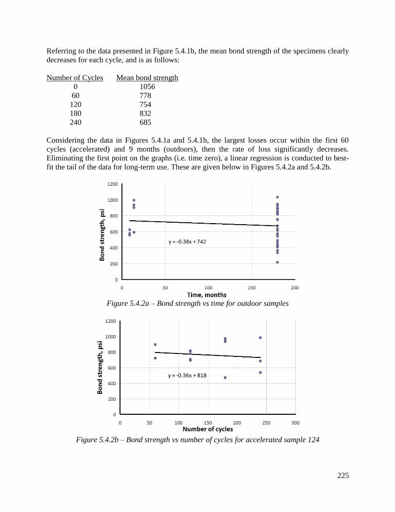
225
Referring to the data presented in Figure 5.4.1b, the mean bond strength of the specimens clearly
decreases for each cycle, and is as follows:
Number of Cycles Mean bond strength
0 1056
60 778
120 754
180 832
240 685
Considering the data in Figures 5.4.1a and 5.4.1b, the largest losses occur within the first 60
cycles (accelerated) and 9 months (outdoors), then the rate of loss significantly decreases.
Eliminating the first point on the graphs (i.e. time zero), a linear regression is conducted to best-
fit the tail of the data for long-term use. These are given below in Figures 5.4.2a and 5.4.2b.
Figure 5.4.2a – Bond strength vs time for outdoor samples
Figure 5.4.2b – Bond strength vs number of cycles for accelerated sample 124

226
For the accelerated data, the resulting regression line becomes: b=818-0.36c, where b is bond
strength and c is number of cycles. For the outdoor samples, the line becomes: b=742-0.38t,
where t is time in months.
To evaluate the long-term acceleration factor, the time and number of cycles required for the
same loss of strength are related. For example, referring to the regression line for the accelerated
samples, a loss of 100 psi of strength (i.e. b=718 psi) can be found to be 278 cycles. Similarly,
for the outdoor samples, it requires 263 months, or 22 years of exposure, for the same loss of
strength (b=642).
The long-term acceleration factor is therefore estimated to be 278 cycles / 22 years =
approximately 12.7 cycles per year.
A similar short-term acceleration factor can be found by using the same process that was used to
develop the long term factor, but now only the initial loss of strength (i.e. at time zero and at the
first 60 cycles) is considered.
For the outdoor specimens, the best-fit regression line between the 0 month and the 9 – 14 month
data is: b = 1003 -19t. For the accelerated specimens, the relationship describing the loss of
strength from time 0 to 60 cycles is: b = 1056 - 4.62c. This results in an estimated short-term
acceleration factor of approximately 207 cycles / 48 months = 4.3 cycles / month = 52
cycles/year (valid for about the first year of exposure).
These acceleration factors may thus be used in future work efforts to estimate bond degradation
without the need for long-term outdoor tests. However, as preliminary estimates for acceleration
factors based on limited data sets and exposure conditions, the values requires refinement with
additional testing. As noted earlier in this chapter, both indoor and outdoor test samples made
during this project continue to be studied in the long-term at Wayne State University.
Using the acceleration factors or the regression fit to the outdoor weathering data directly, long-
term capacity loss can be approximated. In particular, for the outdoor specimens, assuming an
initial strength of 1003 psi, bond strength at the end of the first-year loss is expected to be b =
1003 - 19(12)) = 775 psi, which represents a proportional reduction to 775/1000 = 0.775. In 50
years, for example, the expected bond strength (assuming an initial starting value of 742 psi, per
the regression equation) = 742 - 0.38(49x12) = 519 psi, or an expected additional proportional
reduction to 519/742 = 0.70, which represents a total expected 50 year reduction to 0.775x0.70.
= 0.54 or 54%.
Based on these results, the expected bond strength reduction factor is given below:
Time (years) Reduction factor
10 0.73
25 0.66
50 0.54
75 0.42

227
Possible refinements in this estimate can be made with future testing. As noted above, additional
specimens have been saved for this purpose, and continue to be subjected to outdoor and
accelerated weathering. Any necessary adjustments to the acceleration factor, and resulting
recommendations for environmental reduction factors, will be made available as additional
testing is conducted in future years.
5.4.2 Testing of structural samples
Two types of structural testing are conducted; flexural and confinement. As noted, it was not
possible to obtain the desired failure mode for the shear-strengthened specimens. Flexural
samples include accelerated BASF samples 101 and 102 and identical BASF samples 103 and
104 as control samples. Sample dimensions and flexural test set-up are provided in Section
5.3.5. Three confinement samples were also used; two accelerated and one control. BASF
samples 119 and 120 were accelerated for 60 cycles. The use of this small number of samples
stems from a desire to save as many samples as possible for future use, where longer-term data
are more valuable.
5.4.2.1 Flexural testing
As shown in Figure 5.3.14, the 16” x 4.3” x 4.1” strengthened beams were tested as simply
supported over a 14 in span and loaded at the middle of the span according to ASTM C 293. The
load was applied monotonically using a high–capacity MTS testing machine. Test data is
recorded up to the sample failure. Four beam samples were tested: samples 101 and 102
(accelerated) and samples 103 and 104 (indoor control samples).
Figure 5.4.3 shows a plot of the applied load vs. displacement of accelerated (101 and 102) and
control (103 and 104) beam samples. Test results are presented in Figures 5.4.4-5.4.7.
Accelerated samples (101 and 102) primarily exhibited peeling and debonding failures while the
failure mode of the control beam samples (103 and 104) appears to be combined with shear..
Table 5.4.3 presents the maximum recorded load during testing and the failure mode. Results
reveal that conditioning for only 60 cycles has a significant impact, altering both load carrying
capacity (30% reduction) as well as failure mode.
Table 5.4.3 – Results of accelerated and control flexural beam sample testing
Sample type Sample No. Max. Load, lbs Average/type Failure Mode
Accelerated Beam 101 1301
1412 Peeling
Beam 102 1522 Debonding/peeling
Control Beam 103 1624
2026 Shear/peeling
Beam 104 2427 Shear/debonding

228
Figure 5.4.3 – Load vs displacement for accelerated (101, 102) and control (103, 104) beams
Figure 5.4.4a – Set up of accelerated sample 101
Figure 5.4.4b –Accelerated sample 101 initial cracking
0
1000
2000
3000
4000
5000
6000
7000
8000
9000
0 0.02 0.04 0.06 0.08 0.1 0.12 0.14 0.16
Beam 103
Beam 104
Displacement, in
Mid
-sp
an lo
ad,

229
Figure 5.4.4c –Accelerated sample 101 initial cracking
Figure 5.4.4d –Accelerated sample 101 peeling failure
Figure 5.4.4e –Accelerated sample 101 failure plane
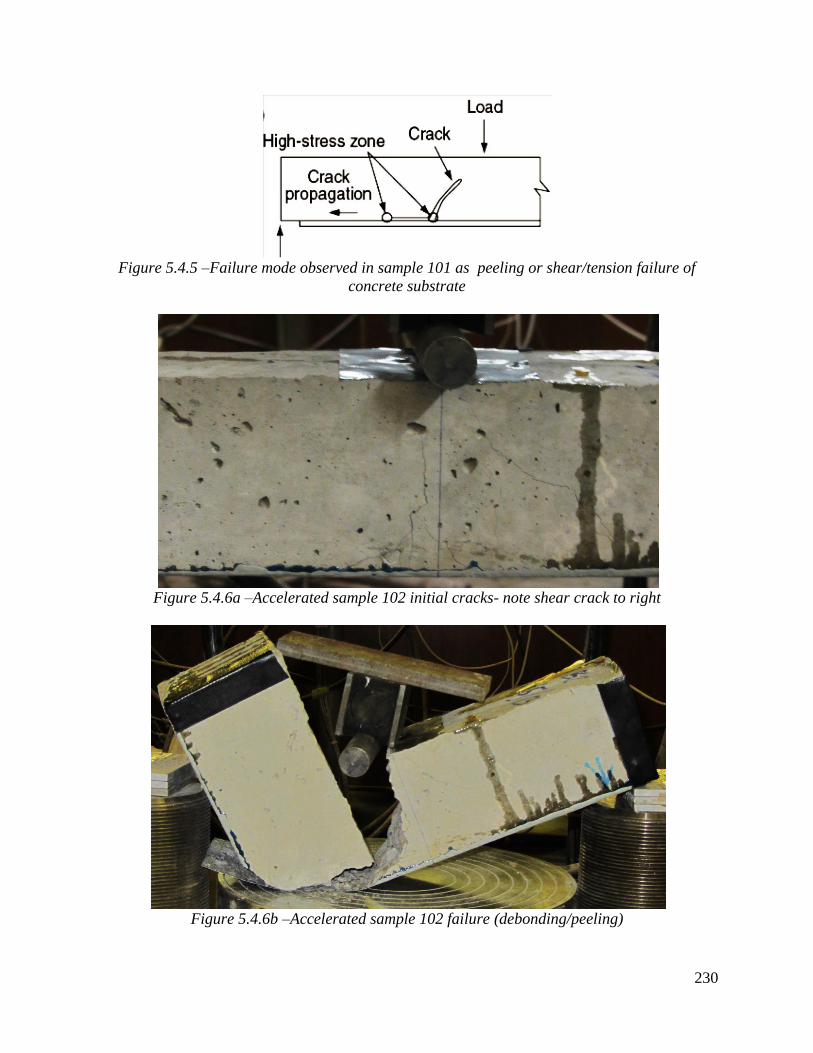
230
Figure 5.4.5 –Failure mode observed in sample 101 as peeling or shear/tension failure of
concrete substrate
Figure 5.4.6a –Accelerated sample 102 initial cracks- note shear crack to right
Figure 5.4.6b –Accelerated sample 102 failure (debonding/peeling)

231
Figure 5.4.7a –Control sample 103 initial hairline cracks (flexure and shear cracks)
Figure 5.4.7b –Control sample 103 shear crack
Figure 5.4.7c –Control sample 103 failure (shear/peeling)

232
Figure 5.4.8a –Control sample 104 initial flexure cracking
Figure 5.4.8b –Control sample 104 progressive cracking
Figure 5.4.8c –Control sample 104 (shear/debonding)

233
5.4.2.2 Confinement testing
Three 4 in x 8 in cylinders were confined using MBrace CF130. Two of the three cylinders
(samples 119 and 120) were conditioned in Tenney environmental chamber for 60 cycles. The
remaining (sample 121) is a control sample maintained in indoor temperature and humidity. The
control sample failed prematurely during testing due to a deficiency at the lower end of the
cylinder causing the concrete to crumble and unwrap the FRP fabric in a domino effect with the
unwrapping travelling upward as the test progressed. The axial load capacity of the control
sample is therefore severely reduced and no meaningful comparison can be made with the
accelerated samples.
However, the accelerated sample testing produced close results between the two samples.
Sample number 119 failed due to FRP failure at the sample mid-section, with a failure load of
141 kips, corresponding to an ultimate compressive strength of 11.2 ksi. Confined sample
number 120 failed due to FRP failure at mid-section as well. Failure load for sample 120 was
133 kips, corresponding to an ultimate compressive strength of 10.6 ksi. Figures 5.4.9-5.4.12
present compressive loads and compressive strengths of accelerated samples, in addition to
photos showing the progressive damage of samples during compressive testing.
Figure 5.4.9 –Compressive strengths of accelerated confined samples 119 and 120, and failed
control sample 121.
0
20000
40000
60000
80000
100000
120000
140000
160000
0 0.05 0.1 0.15 0.2 0.25 0.3
Column 119 Column 120 Column 121 Displacement, in
Co
mp
ress
ive
load
, lb
s

234
Figure 5.4.10 – Confinement sample 121 FRP failure due to lack of end confinement at the
bottom prompting FRP to unravel upward
Figure 5.4.11 –Confinement sample 119 failure due to FRP rupture
Figure 5.4.12 –Confinement sample 120 failure due to FRP rupture

235
5.4.2.3 Summary
Of the structural-level specimen tests conducted, only the flexural specimens provided suitable
results. However, the flexural test results do appear to correspond reasonably well to the pull-off
test results. Figure 5.4.13 replots the accelerated test data (small circles; blue) along with the
flexural tests (large circles; red). On the figure, the flexural test data in Table 5.4.3 are
normalized such that the highest strength control specimen is equated to the highest strength
pull-off specimen, with the remaining three flexural test results proportionally decreased. As
shown on the figure, the normalized flexural test results follow the pull-off test trend closely.
Thus, the corresponding rate of strength reduction at the bond level appears reasonably
correlated to that at the structural failure mode level.
Figure 5.4.13 – Bond strength for pull-off specimens and flexural tests (larger symbols)

236
CHAPTER 6: FIELD TESTS
6.1 Introduction
To assess the pull-off strength of a relatively long-term FRP application, testing of adhesive
bond was conducted on carbon-wrapped columns (numbers 2 and 6; see Figure 6.1) located
beneath an existing bridge (#S09 and S10 of 23152) on west-bound I-96 over Lansing Road in
Lansing, Michigan. The free-standing columns are located on the south/west-bound side of
Lansing Road between the bridge piers and abutment. The tested columns were wrapped with
Masterbuilders MBrace CF130 CFRP in July, 1999. Pull-off sample dollies ware installed on
August 18, 2014 and tested on August 21, 2014. Work was conducted in accordance with
standard installation and test procedures recommended by the test equipment manufacturer. In
this case, 20 mm test dollies were installed using Loctite 907-Hysol Epoxi-Patch adhesive. A
total of 33 dollies were installed on all sides of the two columns, with 4 dollies per face, except
for face number 4 of column 2, where 5 dollies were installed due to the presence of visible
corrosion on the concrete surface (see Figure 6.2). To ensure dollies maintain in contact with the
column surface, rubber elastic membranes were taped to secure the dollies in position until the
adhesive bond was fully developed (Figure 6.3).
Figure 6.1 - Test columns
Figure 6.2 - Test sample location

237
Figure 6.3 - Secured test dollies
Test samples were designated with 3-digit numbers indicating column and face. For example,
sample 621 represents a sample used on column 6, face 2, and number 1 (of 4) on that particular
column face.
6.2 Dolly Installation and Testing
Field work took place on two days; Monday 8/18/14 (installation) and Thursday 8/21/14 (pull-
off testing). Site work on Monday involved the installation of 33 dollies on columns 6 and 2.
The installation process involved cleaning the column surfaces where test dollies were to be
installed; roughening the base surfaces of the dollies using abrasive pads to enhance their
adhesion; applying epoxy to the base of the dollies; then securing the dollies in place to allow the
epoxy to cure by the use of a taped elastic membrane (Figures 6.3 and 6.4).
Figure 6.4 - Test dollies installed on column 2, face 4

238
To allow the epoxy adhesive sufficient time to develop full strength as recommended by the
manufacturer, pull-off testing was conducted three days after installation. The following
procedure was used to prepare samples for testing in accordance with manufacturer’s
recommendations and in conformance to ASTM D4541 (2002):
1. Remove tape and rubber membranes to expose the dollies (Figure 6.5).
2. Core around the base of the dollies to just cut through the carbon strengthening wrap
using a 22 mm diamond coring bit and a drill guide (Figure 6.6). Care was taken not to
cut into the concrete surface, which can influence test results.
3. Conduct adhesion testing with a PosiTest AT-A Automatic Adhesion Tester and record
test data (Figure 6.7).
Figure 6.5 – Removal of tape and elastic membrane to expose dollies for testing
Figure 6.6 – Coring around dollies for proper adhesive bond testing

239
Figure 6.7 –Adhesive bond testing using PosiTest AT-A Automatic Adhesion Tester
6.3 Test Results
Test results are presented in Tables 6.1-6.8, while specimen failure surfaces are given in Figures
6.8 and 6.9. As seen in the tables, there is significant variation in test results, with mean overall
bond strength of 668 psi and mean coefficient of variation (COV) of 0.29 (with range from 0.14-
0.44 per column face). Several failure modes were observed, including concrete, FRP interface,
and combined concrete/FRP interface failures. This variation in failure mode contributes to the
large variation in pull-off strength. However, the majority were concrete failures, indicating the
bond strength was greater than the concrete strength (in pull-off tension) in most cases. In three
cases (samples 634, 644, and 224), the epoxy adhering the dolly to the FRP failed (called
"adhesive" failures in the tables). These results were included, however, as they were within the
strength range of the concrete and FRP failure modes, and represent the lower bound of possible
strength for those particular test cases.
Studying the failure surfaces of the non-concrete failure cases, two reasons were uncovered that
contributed to failure of the adhesive and/or FRP. The first is that the FRP was not fully
saturated with epoxy in all cases. This can be seen most clearly in the case of sample 623,
which had zero pull-off strength as there was practically no epoxy in the FRP at the test location,
as shown in Figure 6.10. The second case was that of air bubbles present in the failure surface.
This was seen throughout multiple samples (212, 612, 232, and 233), as shown in Figure 6.11.
The results of these tests were considered in development of the environmental factors, as
discussed in Chapter 5.

240
Table 6.1 - Column 6, Face 1 test results and failure modes
Sample
Adhesive
Bond
Strength,
psi
Average,
psi
Standard
Deviation
(COV)
Failure
Mode
611 881
796 121
(0.15)
Conc./FRP
612 616 Conc./FRP
613 834 Conc./FRP
614 851 Conc./FRP
Table 6.2 - Column 6, Face 2 test results and failure modes
Sample
Adhesive
Bond
Strength,
psi
Average,
psi
Standard
Deviation
(COV)
Failure
Mode
621 1032
843 180
(0.21)
conc.
622 825 conc.
623 0* FRP
624 673 conc./FRP
*Not included in calculations. Sample fell off upon completion of coring; no pull-off test possible.
Table 6.3 - Column 6, Face 3 test results and failure modes
Sample
Adhesive
Bond
Strength,
psi
Average,
psi
Standard
Deviation
(COV)
Failure
Mode
631 854
650 194
(0.30)
conc.
632 410 conc.
633 747 conc.
634 588* adhesive
Table 6.4 - Column 6, Face 4 test results and failure modes
Sample
Adhesive
Bond
Strength,
psi
Average,
psi
Standard
Deviation
(COV)
Failure
Mode
641 573
548 159
(0.29)
conc.
642 376 FRP*
643 491 conc.
644 753 adhesive
*Evidence of air bubbles.

241
Table 6.5 - Column 2, Face 1 test results and failure modes
Sample
Adhesive
Bond
Strength,
psi
Average,
psi
Standard
Deviation
(COV)
Failure
Mode
211 465
389 144
(0.37)
Conc.
212 335 Conc./FRP*
213 541 Conc.
214 215 Conc.
*Evidence of air bubbles.
Table 6.6 - Column 2, Face 2 test results and failure modes
Sample
Adhesive
Bond
Strength,
psi
Average,
psi
Standard
Deviation
(COV)
Failure
Mode
221 854
800 112
(0.14)
conc.
222 892 conc.
223 638 Conc./FRP*
224 816 adhesive
*Primarily concrete failure
Table 6.7 - Column 2, Face 3 test results and failure modes
Sample
Adhesive
Bond
Strength,
psi
Average,
psi
Standard
Deviation
(COV)
Failure
Mode
231 894
693 275
(0.40)
conc.
232 365 Conc./FRP*
233 566 Conc./FRP*
234 945 conc.
*Evidence of air bubbles.
Table 6.8 - Column 2, Face 4 test results and failure modes
Sample
Adhesive
Bond
Strength,
psi
Average,
psi
Standard
Deviation
(COV)
Failure
Mode
241 405
624 275
(0.44)
conc.
242 424 conc./FRP
243 925 conc.
244 442 conc.
245 924 conc.

242
Figure 6.8 - Column 6 samples after testing

243
Figure 6.9 - Column 2 samples after testing

244
Figure 6.10 –Lack of adhesive bond due to lack of epoxy saturation of sample 623

245
Figure 6.11 –Presence of air bubbles in failure surface of select samples

246
CHAPTER 7: COMPARISON DESIGN
Although the comparison of design provisions in Chapter 3 concerned hypothetical members, in
this Chapter, an existing ACI-based column strengthening design provided by MDOT is
compared to an alternative design using AASHTO provisions. Based on the design
specifications provided, the column and FRP are assumed to have the properties given in Section
7.1.
7.1. Design Assumptions
7.1.1 Column
Original column section dimensions: b = 42’’, h = 84’’; gross area Ag = 3528 in2
As required by ACI, column edges are assumed to be rounded to a minimum radius of = 0.5 in
Total area of steel reinforcement: Ast = 34.36 in2, with yield stress fy = 60 ksi
Concrete compressive strength = 5 ksi
7.1.2 FRP reinforcement
Thickness, tf = 0.04 in
Failure strength, ffu = 340 ksi
Modulus of elasticity, Ef = 23000 ksi
Failure strain, εfu = 0.0147 in/in
Number of layers n = 5
7.1.3 Additional assumptions
ACI 440.2R (ACI Section 12.1.2) states that the provisions provided are not recommended for
columns with a side aspect ratio of h/b greater than 2.0, or face dimension h or b exceeding 36 in,
unless testing demonstrates the effectiveness of the provisions for these cases. As the column
dimensions exceed these limits, it is assumed that the ACI provisions were verified to be
applicable to the column.
As the environmental reduction factor was not explicitly used in the original ACI design, it is
assumed that this factor was accounted for in the provided FRP reinforcement data, which was
reported to have been obtained from laboratory testing.
The original design uses an efficiency factor κε=0.58. However, ACI specifies this factor to be
κε=0.55 (ACI Section 2.1 and in ACI design examples). Therefore, it is assumed that κε=0.55 for
this analysis.
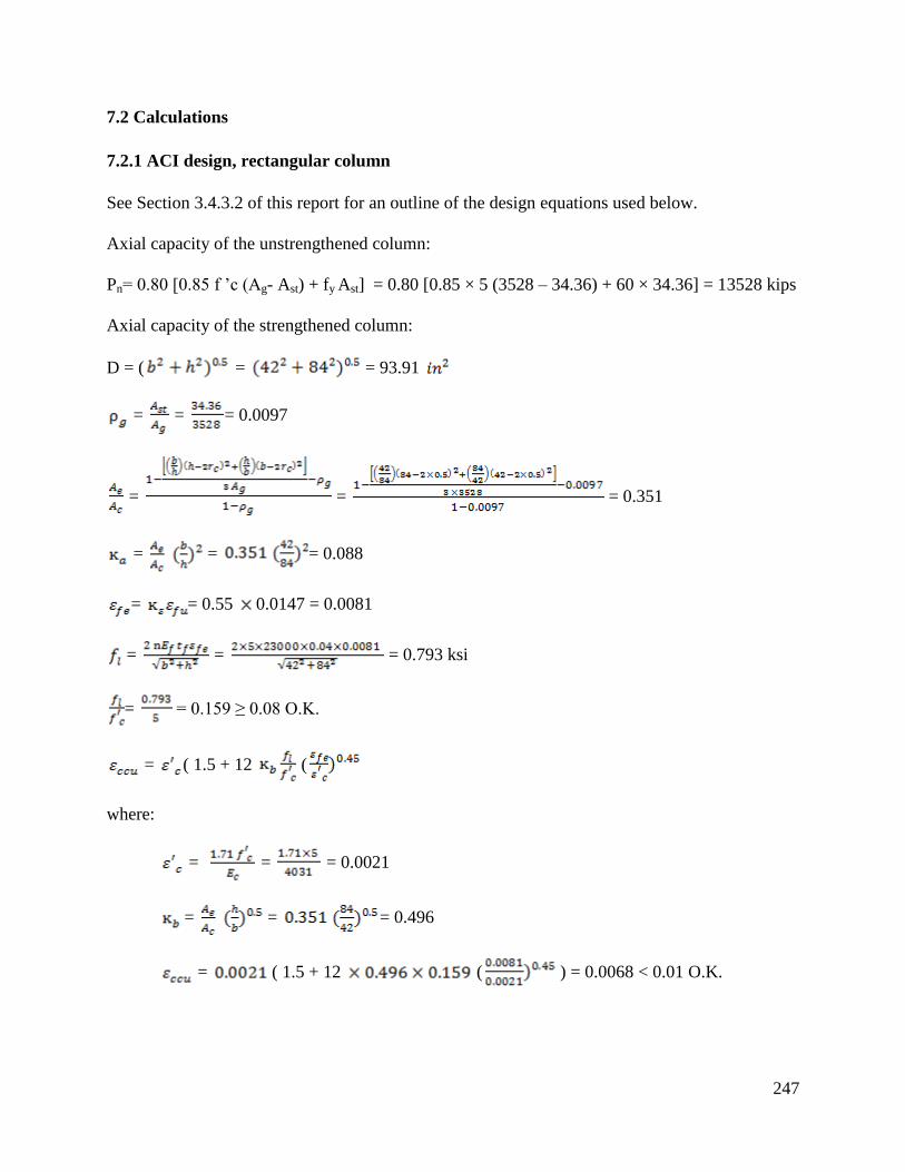
247
7.2 Calculations
7.2.1 ACI design, rectangular column
See Section 3.4.3.2 of this report for an outline of the design equations used below.
Axial capacity of the unstrengthened column:
Pn= 0.80 [0.85 f ’c (Ag- Ast) + fy Ast] = 0.80 [0.85 × 5 (3528 – 34.36) + 60 × 34.36] = 13528 kips
Axial capacity of the strengthened column:
D = ( = = 93.91
= = = 0.0097
= = = 0.351
= = = 0.088
= = 0.55 0.0147 = 0.0081
= = = 0.793 ksi
= = 0.159 ≥ 0.08 O.K.
= ( 1.5 + 12 (
where:
= = = 0.0021
= = = 0.496
= ( 1.5 + 12 ( ) = 0.0068 < 0.01 O.K.

248
= = = 5.218 ksi
Pnc = 0.8[0.85 f’cc (Ag - Ast) + fy Ast] = 0.8[0.85×5.218(3528 – 34.36) + 60 ×34.36] = 14045 kips
This produces a change in capacity of: ΔPn = = = 3.8 %
7.2.2 ACI design, modified column
As an option presented in the original design, the FRP can be applied around a near-circular steel
shell (in plan) which is structurally linked to the column. This allows use of the much more
efficient shape factors κa and κb =1.0 for circular sections rather than the greatly reduced factors
required for rectangular sections. This option is presented below.
Axial capacity of the strengthened column:
D = ( = = 93.91
= = = 0.0097
=
=
=
= 0.55
= = 0.55 0.0147 = 0.0081
= = = 0.793 ksi
= = 0.159 ≥ 0.08 O.K.
= = = 7.486 ksi
= (1.5 + 12 (

249
where:
= = = 0.0021
= (1.5 + 12 ( ) = 0.0105 < 0.01 N.G.
= = 236.76 ksi
= = 5 + (236.76 0.01) = 7.37 ksi
Pnc = 0.8[0.85 f’cc (Ag - Ast) + fy Ast] = 0.8[0.85×7.37 (3528 – 34.36) + 60 ×34.36] = 19158 kips
This produces a change in capacity of: ΔPn = = = 42 %
7.2.3 AASHTO design, rectangular column
See Section 3.4.3.1 of this report for an outline of the design equations used below.
7.2.3.1 Column with confinement pressure limitation imposed
Axial capacity of the unstrengthened column:
Pn= 0.80 [0.85 f ’c (Ag- Ast - Aps) + fy Ast - Aps ( fpe – Ep εcu)]
= 0.80 [0.85 5 (3528 - 34.36 - 0) + 60 34.36 - 0] = 13528 kips
FRP reinforcement strength at a strain of 0.004:
Nfrp= = 3.70 kip/in
fl = = = 0.57 ksi
However, per AASHTO Article 5.3.2.2, the confinement pressure must be no less than 600 psi.
Therefore, revise design to ensure fl = 0.6 ksi.
Set fl = 0.6 ksi and check adequacy:
f = 0.60 ksi ≤ = ( ) = 1.33 ksi O.K.
Nfrp = = = 19.38 kip/ in

250
Required number of plies for fl = 0.6 ksi : n = = = 5.24
Therefore, a minimum of 6 layers is required to meet the minimum confinement pressure.
Axial capacity of the strengthened column (with 6 layers):
fl = = = 0.69 ksi
f’cc = f’c (1 + 2 ) = 5 ( 1+ 2 ) = 6.38 ksi
Pn = 0.8 [0.85 f’cc (Ag - Ast) + fy Ast] = 0.8 [0.85 × 6.38 (3528 - 34.36) + 60 ×34.36] = 16806 ksi.
This produces a change in capacity of: ΔPn = = = 24%
7.2.3.2 Column with confinement pressure limitation eliminated
For comparison, the confinement pressure limitation is removed, and 5 layers are used as with
the ACI design.
Axial capacity of the unstrengthened column:
Pn= 0.80 [0.85 f ’c (Ag- Ast - Aps) + fy Ast - Aps ( fpe – Ep εcu)]
= 0.80 [0.85 5 (3528 - 34.36 - 0) + 60 34.36 - 0] = 13528 kips
FRP reinforcement strength at a strain of 0.004.
Nfrp= = 3.70 kip/in
fl = = = 0.57 ksi
f = 0.57 ksi ≤ = ( ) = 1.33 ksi O.K.
Nfrp = =
= 18.4 kip/ in
Required number of plies for fl = 0.57 ksi : n = =
= 5
Axial capacity of the strengthened column (with 5 layers):

251
fl = =
= 0.57 ksi
f’cc = f’c (1 + 2 ) = 5 ( 1+ 2
) = 6.14 ksi
Pn = 0.8 [0.85 f’cc (Ag - Ast) + fy Ast] = 0.8 [0.85 × 6.14 (3528 - 34.36) + 60 ×34.36] = 16236 ksi.
This produces a change in capacity of: ΔPn = =
= 20%
7.2.4 AASHTO design, modified column
7.2.4.1 Modified column with confinement pressure limitation imposed
Axial capacity of the unstrengthened column:
Pn= 0.80 [0.85 f ’c (Ag- Ast - Aps) + fy Ast - Aps ( fpe – Ep εcu)]
= 0.80 [0.85 5 (3528 - 34.36 - 0) + 60 34.36 - 0] = 13528 kips
FRP reinforcement strength at a strain of 0.004:
Nfrp= = 3.70 kip/in
fl = = = 0.256
However, per AASHTO Article 5.3.2.2, the confinement pressure must be no less than 600 psi.
Therefore, revise design to ensure fl = 0.6 ksi.
Set fl = 0.6 ksi and check adequacy:
f = 0.60 ksi ≤ = ( ) = 1.33 ksi O.K.
Nfrp = = = 43.35 kip/ in
Required number of plies for fl = 0.6 ksi: n = = = 11.71
Therefore, a minimum of 12 layers is required to meet the minimum confinement pressure.
Axial capacity of the strengthened column (with 12 layers):

252
fl = = = 0.61 ksi
f’cc = f’c (1 + 2 ) = 5 ( 1+ 2 ) = 6.22 ksi
Pn = 0.8 [0.85 f’cc (Ag - Ast) + fy Ast] = 0.8 [0.85 × 6.22 (3528 - 34.36) + 60 ×34.36] = 16426 ksi.
This produces a change in capacity of: ΔPn = = = 21 %
7.2.4.2 Modified column with confinement pressure limitation eliminated
For comparison, the confinement pressure limitation is removed, and 5 layers are used as with
the ACI design.
Axial capacity of the unstrengthened column:
Pn= 0.80 [0.85 f ’c (Ag- Ast - Aps) + fy Ast - Aps ( fpe – Ep εcu)]
= 0.80 [0.85 5 (3528 - 34.36 - 0) + 60 34.36 - 0] = 13528 kips
FRP reinforcement strength at a strain of 0.004:
Nfrp= = 3.70 kip/in
fl = = = 0.256
f = 0.256 ksi ≤ = ( ) = 1.33 ksi O.K.
Nfrp = =
= 18.5 kip/ in
Required number of plies for fl = 0.256 ksi: n = =
= 5
Axial capacity of the strengthened column (with 5 layers):
fl = =
= 0.256 ksi
f’cc = f’c (1 + 2 ) = 5 ( 1+ 2
) = 5.51 ksi
Pn = 0.8 [0.85 f’cc (Ag - Ast) + fy Ast] = 0.8 [0.85 × 5.51 (3528 - 34.36) + 60 ×34.36] = 14740 ksi.
253
This produces a change in capacity of: ΔPn = =
= 9%
7.3 Summary
As was shown in Chapter 3 (Section 3.4.4), for the same number of layers, ACI predicts larger
capacity increases for strengthening circular columns, while AASHO predicts larger capacity
increases for strengthening square columns.
Using 5 layers of FRP, the ACI design produced a capacity increase of 4% for the rectangular
column and 42% for the modified (circular) column. Similarly, in the AASHTO procedure, if
the minimum confinement strain requirement of 0.6 ksi is not enforced, 5 layers produces a 9%
increase for the rectangular column and a 20% increase for the modified column. Imposing the
confinement strain provision in AASHTO results in a requirement for 6 layers but provides a
24% increase in capacity for the rectangular column. For the modified column, however,
imposing the confinement strain provision requires 12 layers and only provides a 21% increase
in capacity.

254
CHAPTER 8: RECOMMENDATIONS
8.1 Analysis and Design Recommendations
8.1.1 Criteria for recommendations
Most of the codes reviewed have reasonable coverage of the major design and analysis areas
(flexure, shear, confinement). To guide selection of appropriate provisions, the following
primary criteria were considered:
1) Accuracy. It is essential that a recommended provision accounts for the phenomenon that it
attempts to address with sufficient accuracy. In general, this can be established with adequate
documentation in the code commentary, to demonstrate theoretical soundness and/or convincing
experimental evidence for empirically-based provisions. Documentation may include references
to appropriate technical papers, reports, or other published sources, most of which are included
in the literature review section of this report. As shown in earlier sections of this document, the
reviewed codes contain varying levels of documentation for their recommendations.
2) Format compatibility. From a practical point of view, it is important that recommended
provisions are compatible with existing bridge design and analysis procedures used by MDOT.
This is particularly important when considering strength reduction factors that modify
expressions for capacity. Such factors may have been developed for building loads, for example,
which have different levels of uncertainty than traffic loads. Similarly, manufacturing and
environmental factors may reflect conditions that are not representative of those in Michigan.
3) Clarity and ease of use. Often, provisions produce similar outcomes, but achieve the outcome
with different procedures, equations, and processes. Clearly, a balance must be drawn between
accuracy and ease of use. As this report concerns recommendations for design and evaluation, a
large increase in complexity that provides a minimal gain in accuracy may not be appropriate.
Clarity and ease of use can be evaluated is in terms of the procedures and models used, and even
the symbols and nomenclature used in the relevant expressions. Clarity also concerns similarity
to the existing methods that designers are familiar with.
8.1.2 General recommendation and discussion
Based on the criteria considered above, it is recommended that the AASHTO guidelines
(AASHTO Guide Specification for the Design of Bonded FRP Systems for Repair and
Strengthening of Concrete Bridge Elements) are used as the base analysis and design document,
with some recommended modifications, as discussed below. The AASHTO Guide covers most
areas of concern with good documentation of accuracy, and results calculated from the AASHTO
provisions generally fall with the range of outcomes of the other codes considered. Moreover,
the document is specifically written for bridge structures, and is directly compatible with the
AASHTO LRFD design provisions. The format, notation, and procedures within are also
familiar to MDOT engineers. A brief summary of the reasoning for recommending the
AASHTO provisions is discussed below. Refer to Chapter 3 of this report for additional detail.

255
Strengthening limits for fire endurance. ACI 440.2R provides strengthening limitations to allow
a structure to maintain a minimum specified strength if the external FRP strengthening system is
weakened in a fire. The use of this expression, however, requires evaluation of existing
structural capacity at high temperatures, which introduces complexity that may not be desirable.
Although AASHTO does not directly address this issue, AASHTO does provide a general
strengthening limit expression when FRP is considered. As discussed in Section 3.2.2, this
existing provision provides a strengthening limit outcome similar to that presented by ACI.
Therefore, the existing AASHTO expression is recommended without modification.
FRP strain limits. To prevent debonding, AASHTO specifies that the FRP strain may not exceed
0.005 less initial strain (for flexure). AASHTO adds a second strain condition to ensure ductile
behavior post steel yielding. AASHTO stipulates that the ultimate FRP strain equals 2.5 times
FRP strain at the point of steel yielding. These strain limit requirements are slightly more
conservative than some other codes (see Section 3.2.4 of this report and Figures 3.2.4 and 3.2.5),
but are deemed reasonable for reinforced concrete structures. However, as discussed below,
these may not be suitable for prestressed concrete girders.
Strength reduction factors for FRP. The majority of codes use a FRP strength reduction factor
close to 0.85 as indicated in Table 3.2.10 and discussed in Section 3.2.5. Some codes such as
TR55 adopt a more detailed procedure to account for different FRP materials, manufacturing
processes, and exposure conditions to produce a combined factor for specific cases. This
approach offers flexibility, but unfortunately, most of the values recommended are
undocumented or rely on manufacturer test data that may not follow common standards or
regulations. The common global value adopted by AASHTO of 0.85 is based the work by Okeil
et al. (2007) that is based on reliability analysis and accounting for the brittle nature of CFRP.
Due to the lack of information to justify a more detailed system, and as the AASHTO-specified
value is similar to that adopted by other codes, it is recommended for use.
Serviceability, service load limits, creep rupture and fatigue limits. The AASHTO serviceability
limits are 0.80 fy for steel; 0.36 f'c for concrete; and 0.80 ffu for CFRP. These values are similar to
those adopted by ACI, except for the FRP limit since AASHTO has no considerations for an
environmental reduction factor which is built in the ACI factor of 0.55ffu. Both ACI and
AASHTO reference the work of Yamaguchi et al. (1997) and Malvar (1998) as a basis for
fatigue limits. No other codes offer a complete set of serviceability limits. AASHTO fatigue
limits are comprehensive as well, with strain limits given for concrete, steel, and FRP, and are
recommended.
FRP end peeling. End peeling limits vary from a constant value specified by TR55, an
expression by ACI relating the shear force to concrete shear resistance (as a function of section
geometry and concrete compressive strength), and expressions by AASHTO that account for
FRP thickness, adhesive properties and concrete compressive strength. As shown in Figures
3.2.15 and 3.2.16, the AASHTO peeling limits compare closely to those of CNR. The work of
Naaman et al. (1999) is the basis for the limits adopted by AASHTO. This work specifically
considered environmental conditions similar to those in Michigan, as discussed in Section 3.2.7,
and is considered to be most appropriate for MDOT bridges.

256
Development length. The expression for development length presented by AASHTO is
somewhat different from that of the other codes; it is substantially more sensitive both to f’c as
well as the amount of FRP provided, as shown in Section 3.2.9. However, the AASHTO
expression was developed by Naaman et al. (1999) and specifically considered Michigan
environmental conditions. It is therefore recommended for use on this basis.
Shear and confinement strengthening. Variations in shear and confinement strengthening
provisions are minimal among the different codes. Based on this similarity, there is no
theoretically compelling reason to deviate from the AASHTO provisions. However, due to the
AASHTO requirement that a minimum confinement pressure of 0.6 ksi is met (see Table 3.4.3),
AASHTO may often require a larger amount of FRP than theoretically necessary to increase
capacity. Therefore, two alternatives are recommended for consideration of confinement
strengthening: the AASHTO provisions as well as the ACI provisions. The latter is
recommended as it may be more economically feasible than the AASHTO approach for some
columns. In particular, as ACI does not specify a minimum required confinement pressure, it
may achieve the same strengthening result as AASHTO but with less FRP material.
8.1.3 Recommended modifications to AASHTO provisions
Although the AASHTO provisions are generally recommended, some shortcomings in the
AASHTO guidelines have been identified. To address these shortcomings, the following
modifications are suggested:
8.1.3.1 Environmental reduction factors
AASHTO provides no specific environmental reduction factors. Rather, a minimum assumed
interface shear strength is provided ( = 0.065 ), which is also used to evaluate peeling (eq.
3.2.37) as well as development length (eq. 3.2.50). Therefore, the reduction factor below should
be applied to the interface shear strength of the system, , the value of which is obtained from
the manufacturer or from appropriate experimental testing as noted in section 8.2.4.2. Based on
the experimental phase of this project (Chapter 5), the following Michigan-specific reduction
factors for CFRP interface bond strength are recommended (linear interpolation is permitted):
Time (design years) Reduction Factor
10 0.73
25 0.66
50 0.54
75 0.42
These values are to be multiplied by the determined for the specific FRP system (not the
value of 0.065 provided by AASHTO, which is likely much lower than the actual ). It
should be emphasized that the reduction factor is applied to only and not directly to the
section capacity in the form of an overall strength reduction factor.

257
As detailed in Chapter 5, a 15-year reduction factor was determined experimentally from
measured reductions in bond strength of CFRP wrap exposed to Michigan weather, while shorter
and longer term reduction factors were determined by extrapolation with best-fit linear
regression models.
Multiple-year reduction factors are presented since it may make sense to apply a reduction factor
corresponding to the anticipated remaining service life of the component to which the FRP is
applied. However, if uncertain, this time should be conservatively estimated.
Although long-term reduction factors are large, if common epoxy strengths and appropriate
surface preparation and installation techniques are used, as in accordance with the
recommendations of this chapter, it is likely that no environmental reductions in capacity will
occur in most cases. This is because the interface shear strength assumed by AASTHO is very
low ( = 0.065 ), and most FRP installations are expected to have initial values greater
than twice this amount. Thus, even applying a large, long-term reduction factor for 50-75 years
would result in a design shear strength greater than the minimum specified by AASHTO,
resulting in a potential increase in peeling strength (eq. 3.2.37) and decrease in allowable
development length (eq. 3.2.50).
8.1.3.2 Flexural design when considering compression failures
Although tension failures are clearly desired, in many cases it is not possible to meaningfully
strengthen with FRP and maintain a tension-controlled section. This is particularly so for
prestressed concrete sections, but is not directly addressed in AASHTO. In the case of a
compression controlled section, it is recommended that in the capacity analysis, the AASTHO-
specified FRP strain limit (at ultimate capacity) should correspond to a maximum concrete
compressive strain in the girder of 0.003. If the resulting FRP strain is less than 0.005, the FRP
reinforcement strength per unit width, , should be calculated based on the FRP strain
calculated at concrete compressive failure, not 0.005.
8.1.3.3 Initial strain for prestressed sections
For the strengthening analysis of prestressed concrete sections, the initial strain at the bottom
of the beam (FRP/concrete interface) must be calculated. Although not addressed in AASHTO,
this expression can be theoretically derived and is given in ACI, which is recommended for use
(ACI Eq. 10-18):
=
) +
(8.1)
where:
εpi = initial strain level in prestressed steel reinforcement, in/in (mm/mm)
Pe = effective force in prestressing reinforcement (after allowance for all prestress losses), lb (N)
Ap = area of prestressed reinforcement in tension zone, in2 (mm
2)
Ep = modulus of elasticity of prestressing steel, psi (MPa)

258
e = eccentricity of prestressing steel with respect to centroidal axis of member at support, in
(mm)
r = radius of gyration of a section, in (mm)
8.1.3.4 Strength reduction factors and ductility provisions considering prestressed sections
To ensure ductility, AASHTO limits specify that the strain developed in the FRP reinforcement
at section ultimate capacity must be equal to or greater than 2.5 times the strain in the FRP
reinforcement at the point where the centroid of steel tension reinforcement yields. With a
maximum useable strain of 0.005 at the FRP reinforcement/concrete interface, the maximum
effective strain developed in the FRP reinforcement is , where εbo is the initial
tensile strain at the bottom concrete surface as a result of the moment due to dead load (the
existing tensile strain prior to FRP installation). When the FRP is applied, the steel will have
some initial strain due to dead load moment (εd). Since the FRP is bonded to the outside of the
beam, it is placed further away from the neutral axis in the section than the steel. Therefore, the
FRP will have a minimum strain value of εy-εd when the steel yields, where εy is steel yield
strain. Following the AASHTO provisions, at ultimate flexural capacity, strain in the FRP must
be greater than the minimum possible value of 2.5(εy - εd). For prestressed beams, the steel
effective prestrain (εp) must also be considered, such that the strain in the FRP at ultimate
flexural capacity must be greater than 2.5(εy - εd – εp). However, for the high-grade steel used for
prestressing, εy is large, and the value of 2.5(εy - εd - εp) may exceed the allowable FRP strain
limit of 0.005 - εbo. This limitation will not allow any flexural FRP strengthening to be applied
to prestressed beams in many cases. Reasonable changes in the concrete constitutive model does
not alter this result. ACI provisions solve this problem by allowing such sections to be
strengthened, but to account for the possible loss in ductility, the section strength is penalized
with a lower resistance factor. However, for the practical cases of prestressed concrete girders
investigated, it was found that the ACI approach often leads to high requirements of FRP
reinforcement as well as a resistance factor of 0.65. The former occurs because the ACI
debonding limit, which limits the usable strain in the FRP (eq. 3.2.8), is a function of the amount
of FRP applied; as the amount of FRP is increased to meet flexural demand, this strain limit
decreases. It was found that the resulting value is often lower than the value of 0.005 specified
with the AASHTO provisions. Moreover, as FRP area is increased, strain in the prestressing
steel at failure generally decreases, thus lowering resistance factor, often to 0.65. Therefore,
direct use of the ACI strengthening provisions with prestressed griders was also found to be
impractical in many cases. Therefore, an alternative approach is recommended for
consideration, based on a modification of the existing AASHTO procedure.
This approach utilizes the AASHTO FRP strain limit addressed in Section 8.1.2. For
consistency, the same methodology is recommended for both non-prestressed as well as
prestressed sections, with appropriate adjustments in strain limits. This approach combines
AASHTO and ACI limits and reduction factor concepts to produce a more practical
strengthening procedure for some cases. For non-prestressed sections, the resistance factor for
flexural capacity for concrete beams with FRP strengthening is recommended to be taken as:

259
005.0005.0
)(25.065.0
5.215.1
25.065.0
min
tsy
sy
syt
FRPyFRPuFRPyFRPu
for
for
(8.2)
where:
εt = strain in the lowest layer (i.e. furthest away from the compression side of the beam) of steel
at ultimate capacity, where ultimate capacity is limited by either (whichever occurs first)
concrete crushing, FRP rupture, or FRP debonding (at an assumed maximum interface strain of
0.005 given by AASHTO)
εFRPu = strain in the FRP at ultimate capacity
εFRPy = strain in the FRP when steel yields
The above factor is to be applied to the entire flexural capacity expression, including steel and
FRP-based capacity components. In addition, the FRP portion of capacity is further reduced by
the additional resistance factor given as:
FRP
6.038.0 FRP
FRP
(8.3)
Note that practically, due to the usable FRP strain limit specified by AASHTO of 0.005, = 0.90
cannot be achieved due to the requirement of εt ≥ 0.005. However, in most cases, if maximum
FRP strain is set to 0.005, εt will only be slightly less than this value, resulting in between
0.85-0.90.
For prestressed concrete members (using 250-270 ksi prestress steel), the following is
recommended:
013.0010.0010.0013.0
)010.0(25.065.0
5.215.1
25.065.0
min
ps
ps
FRPyFRPuFRPyFRPu
for
for
(8.4)

260
where:
εps = The prestressing steel strain (at steel centroid) at ultimate capacity. The same FRP
reduction factor as above is applied to the FRP portion of resistance.
εps = εpe +
( 1 +
) + εpnet ≤ 0.035 (3.5.5)
εpe =
(3.5.6)
εpnet =
(3.5.7)
Note that practically, due to the usable FRP strain limit specified by AASHTO of 0.005,
εps ≤ 0.010 and thus = 0.65. However, the above equations retain validity if the AASHTO
FRP strain limit of 0.005 is adjusted to a new value. Increasing this value will allow an increase
in the strength reduction factor for prestressed members beyond 0.65.
In most cases, this approach will provide a resistance factor that is very close (slightly
conservative) to that specified by AASHTO if AASHTO ductility criteria are met. If AASHTO
criteria are not met, beam strengthening is allowed but with a reduced resistance factor similar to
the ACI approach as a function of beam ductility.
Note that, to determine the most appropriate resistance factors and associated strain limits, a
structural reliability analysis of FRP-strengthened prestressed concrete girders, subjected to
Michigan bridge loads, is needed. However, this analysis is beyond the scope of this report.
Therefore, with the recognition that the existing provisions were not specifically developed for
strengthening prestressed concrete bridge girders, the recommended procedure may be a
reasonable alternative to consider until desired reliability or revised guidelines results become
available. Some design examples using the recommendations are given in Appendix B.
8.2 Installation, QC, and Maintenance Recommendations
For all sources examined, there is a nearly universal suggestion or requirement to follow the FRP
system manufacturer’s recommendations. Therefore, it is recommended that:
1) The installer is required to provide documentation of manufacturer recommendations for
installation, QC, and maintenance, as available, and that these recommendations are followed.
Deviation from these recommendations are to be made only for compelling reasons, and should
have approval of the design engineer (who should have extensive experience with FRP
strengthening of bridge structures), and MDOT. The proposed deviation should be accompanied
with sufficient documentation and/or justification, preferably with quantitative analysis and/or
experimental test data.

261
2) If the manufacturer does not provide recommendations in a particular instance, the following
guidelines are recommended. In all cases, it is suggested the manufacturer is consulted for
comment on the provisions before use.
A checklist of inspection items following the recommendations below is given in Appendix C,
while suggested changes to the existing MDOT Provisions for FRP strengthening are given in
Appendix D.
8.2.1 Shipping, storage, and handling
8.2.1.1 Shipping
As AASHTO has no specific shipping recommendations, in general, the ACI shipping guidelines
are recommended. In particular, packaging, labeling, and shipping for thermosetting resin
materials are to be controlled by the Code of Federal Regulations 49 (CFR 49), in which some
FRP system materials may be classified as corrosive, flammable, or poisonous in Subchapter C
(CFR 49). As such, FRP system constituent materials are to be packaged and shipped in a
manner that conforms to all applicable federal and state packaging and shipping codes and
regulations. The following additional provisions are suggested:
It is the duty of the contractor and supplier to ensure that the packaging and shipping methods
used do not negatively impact material properties and performance.
All FRP components must be shipped with their respective SDSs.
All components of the FRP system are to be inspected upon delivery to the construction site, and
the use of opened or damaged containers should only proceed with written authorization by the
project Engineer.
8.2.1.2 Storage
Although AASHTO provides no storage guidelines, ACI Article 5.2 offers the most complete
coverage of storage and disposal of expired materials (Article 1.2), and these provisions are
recommended in general, with the following additional comments.
All FRP system components must be stored in the original factory-sealed, unopened packaging
with labels identifying the manufacturer, brand name, system identification number and date.
Proper storage of FRP components is in a clean, dry area, sheltered from direct sunlight, which is
well ventilated and temperature controlled within 50°–75°F (10°–24°C). Catalysts and initiators
(e.g., peroxides) should be stored separately.
As possible, components stored on the jobsite should be periodically inspected in accordance
with the inspection checklist presented in Appendix C; components that have been stored in a
condition different from that stated above are to be rejected.

262
Of particular concern are reactive curing agents, hardeners, initiators, catalysts, and cleaning
solvents which have special safety-related requirements, and are to be stored in securely sealed
containers in a manner recommended by OSHA. As resins are also flammable, fire precautions
should be observed and storage quantities kept within limits prescribed by fire regulations.
The manufacturer is to provide a recommended shelf life within which the properties of the
resin-based materials should continue to meet or exceed the stated performance, and the
contractor must follow these time limits.
Any component material that has exceeded its shelf life, has deteriorated, or has been damaged
or otherwise contaminated should not be used. Care must be taken to avoid laminate and other
preformed material damage due to bending or improper stacking. FRP materials deemed
unusable should be disposed of in a manner acceptable to state and federal environmental control
regulations.
8.2.1.3 Handling
ACI Article 5.3 provides the most complete coverage of safe handling of FRP materials as
compared to other codes. ACI is therefore generally recommended for use, with the following
additional comments.
Information regarding proper storage, handling, and mixing resin components and potential
hazards should be made available at the construction site.
Product hazard labels and associated SDSs are to be read and understood by those working with
these products. CFR 16, Part 1500 (2009), regulates the labeling of hazardous substances and
includes thermosetting-resin materials. Such labeling guidelines should be followed.
Disposable suits and gloves resistant to resins and solvents should be used for handling fiber and
resin materials, where gloves should be discarded after each use. Safety glasses or goggles
should be used when handling resin components and solvents, and surfaces should be covered as
needed to protect against contamination and resin spills.
Respiratory protection, such as dust masks or respirators, should be used when fiber fly, dust, or
organic vapors are present, or during mixing and placing of resins. The workplace in which
composite materials are prepared and installed should be well ventilated; in poorly ventilated
areas, the use of respiratory protection with a fresh air supply is recommended.
Uncontrolled reactions, including fuming, fire, or violent boiling, may occur in containers
holding a mixed mass of resin; therefore, such containers should be monitored.
As cleanup can involve flammable solvents, appropriate safety precautions are suggested. All
waste materials are to be disposed of as prescribed by the prevailing environmental authority.
It is the contractor's responsibility to ensure that all components of the FRP system at all stages
of work conform to governing environmental and safety regulations.

263
All FRP components, but especially fiber sheets, must be handled with care to protect them from
damage and to avoid misalignment or breakage of the fibers; excessive bending, crushing and
other sources of mechanical damage to the fibers must be avoided. Higher modulus fibers are
particularly susceptible to such damage. After cutting, sheets should be either stacked dry with
separators, or rolled gently at a radius no tighter than 12 in (305 mm). Special care should be
taken to avoid material contact with water, dust or other contaminants.
8.2.2 Manufacturer and contractor qualification
For manufacturer and contractor qualification, AASHTO refers to NCHRP 609, which gives
relatively comprehensive qualification requirements as compared to other sources. NCHRP 609
is thus recommended as a qualification guide, with the following summary of these
recommendations, as well as additional comments.
FRP application must be performed by a contractor specifically trained in accordance with the
installation procedures specified by the manufacturer. These procedures may differ from one
system to another, and thus general knowledge of FRP installation is of itself not sufficient.
The proposed manufacturer may be pre-qualified for each FRP system to be installed, after
providing the following information to a qualified engineer for review and consideration:
System data sheets and SDS for all components of the FRP system;
Documentation of a minimum of 5 years’ experience with the FRP system, or 25 documented
similar field applications with acceptable reference letters from respective owners;
Documentation of test data sets from an independent agency verifying the mechanical
properties, aging and environmental durability of the proposed FRP system, and;
Documentation of the availability of a comprehensive hands-on training program for each
FRP system that can be taken by the staff of the contractor/applicator.
MDOT may further opt to require the manufacturer to provide samples of the components, as
well as of the complete FRP system for in-house or independent testing prior to qualification.
The training program conducted by the manufacturer should provide hands-on experience with
surface preparation and installation of the specific FRP system which is to be installed.
Additionally, it is recommended that:
MDOT may further opt to require that the contractor demonstrate competency by an actual
demonstration of surface preparation and installation.
The contractor must provide a detailed statement of the method which will be used to install the
composites as well as an assessment of the risks (failing to meet system performance
requirements as well as health and construction hazards) involved. This should include
discussion of the procedure which will be used to minimize these risks. The contractor should
further provide description of a plan that will be used to maintain an environment on-site that is
suitable for the successful use of structural adhesives. Note that many of these items are typical
requirements for the contractor-submitted QC plan.
264
8.2.3 Installation
Most codes reviewed provided similar recommendations. Provisions provided by ACI are
generally most complete and are recommended, with some additional provisions from AASHTO
and other codes, as detailed below.
8.2.3.1 Temperature, humidity, and moisture considerations
Primers, saturating resins, and adhesives should generally not be applied to cold or frozen
surfaces, which can affect bond as well as rate of curing, and the presence of frost or ice crystals
may be detrimental to the bond between the FRP and the concrete. In particular, ambient air and
concrete surface temperature should be 50° F (10° C) or more; the concrete surface temperature
should be at least 5° F (3° C) higher than the actual dew point; and atmospheric relative humidity
should be less than 85%. A non-contaminating heat source can be used to raise the ambient and
surface temperatures during installation if needed.
During application of epoxy, work should be scheduled to avoid air and surface temperatures
exceeding 90° F (32° C). If necessary, then the work should be supervised by a person
experienced in applying epoxy under such conditions. Epoxy systems formulated for elevated
temperatures are available, and should be considered as well (see ACI 530R-93). It is also
recommended not to install FRP when the concrete surface is heavily exposed to sunlight.
Adhesives should not be applied to damp or wet surfaces with surface humidity greater than
10%, unless they have been formulated for such applications. Substrate humidity can be
evaluated with a mortar hygrometer or other quantitative means. Moreover, FRP systems should
not be applied to concrete surfaces that are subject to condensation, moisture vapor transmission,
or water ingression, unless such issues are clearly addressed by the system design and the resin
systems are specifically formulated for use in such conditions. ACI Standard 503.4 (2003)
provides additional moisture content requirements. Note that the transmission of moisture vapor
from a concrete surface through the uncured resin materials typically appears as surface bubbles
and can compromise the bond between the FRP system and the substrate. Condensation or other
moisture on the resin surface before initial hardening, indicated by whitening, the area should be
wiped with solvent or the effected portion of primer or smoothing agent removed with
sandpaper.
8.2.3.2 Equipment
All equipment should be clean, in good operating condition, and accessible for inspection by the
project engineer. Note that some FRP systems recommend or require specific equipment for
application, such as resin impregnators, sprayers, lifting/positioning devices, and winding
machines. The contractor is to have qualified personnel sufficiently trained to install and operate
such system-specific equipment, such as by training and/or certification from the FRP system
manufacturer, if available. All materials, and supplies, and personal protective equipment should
be available in sufficient quantities to allow safe construction continuity and quality assurance.

265
8.2.3.3 Substrate repair
The surface on which the FRP system is to be applied should be free of loose and unsound
materials; unfit existing conditions may require repair. The quality of the substrate can be
checked with testing. Compressive strength should not be less than 2.2 ksi (15 N/mm2), and the
concrete surface must have a minimum tensile strength of 220 psi (1.5 MPa), as measured by a
pull-off tension test in accordance with ASTM D4541 (2002). For concrete surfaces that require
repair, general methods are provided in ACI 546R (2004) and ICRI 03730 (2008). However, the
concrete surfaces must be repaired or reshaped in accordance with the original section.
Before any epoxy or putty-based products are applied for repair, and all contaminants that could
interfere with the bond should be removed. The concrete surface preparation should be
inspected and approved by the project engineer before such repairs. If cementitious materials are
used for repair, they should be allowed to sufficiently cure (i.e. when it is expected to have
reached its minimum specified compressive strength) reach before further surface preparation. If
corrosion-related concrete deterioration is detected, the cause of the corrosion should be
addressed, and the associated deterioration repaired before application of the FRP system.
To repair cracks, those wider than 0.010 in (0.3 mm) should be pressure injected with epoxy
before FRP installation, in accordance with ACI 224.1R (2007). Cracks of smaller width may
require resin injection or sealing to prevent corrosion of existing reinforcement. ACI 224.1R
(2007) provides additional crack-width limitations based on different exposure conditions.
If there is uncertainty in the best approach, a trial run of the surface preparation process should
be conducted to determine an effective technique for the FRP system to be used, and approved
by the project engineer.
8.2.3.4 Surface smoothness
For contact-critical applications such as confinement (i.e. those in which loss of bond between
the concrete and FRP is not critical, but contact between the surfaces must be maintained), the
surface preparation should guarantee a continuous contact between the concrete and the FRP
confinement system. After repair (if needed), the concrete surface should be prepared to a
minimum concrete surface profile (CSP) 3, as defined by ICRI surface profile chips, and
localized out-of-plane variations, including form lines, should not exceed 1/32 in (1 mm).
Localized variations can be removed by grinding, or can be smoothed over using resin-based
epoxy if variations are small. It is best that epoxy materials are applied in thin layers to build up
to the desired flatness. Bug holes and voids should be filled with resin-based putty. However,
before application of any fillers, the surface must be appropriately cleaned to ensure bond of the
repair materials. The maximum size allowed for small depressions is shown in Table 8.2.1.
Table 8.2.1 – Maximum depth of depressions on the concrete surface
Type of FRP Max. depth for length
of 12 in (0.3 m), in
Max. depth for length of
80 in (2.0 m), in
Plates 0.16 in (4.0 mm) 0.40 in (10.0 mm)
Plates ( ) 0.08 in (2.0 mm) 0.24 in (6.0 mm)
Sheets 0.08 in (2.0 mm) 0.16 in (4.0 mm)

266
Rectangular cross-sections should have corners rounded to a minimum radius of at least 0.5-1.4
in (13-35 mm). This applies for corners both horizontally and vertically oriented. Chamfered
corners are not recommended as a substitute for rounded corners. Larger radii should be used if
forming and bonding the FRP to the member corner becomes difficult, which may occur as the
thickness and stiffness of the FRP material used increases. Rough corners should be smoothed
with epoxy or putty. Inside corners and concave surfaces may be difficult for FRP application,
may require special attention to ensure that bond is achieved between the FRP and the concrete.
8.2.3.5 Surface cleanliness
Before application of the FRP, the concrete surface should be cleaned to remove any dust,
laitance, oils, dirt, or any other bond-inhibiting material. Even new concrete should be cleaned to
remove mold release agents and curing membranes.
Various cleaning techniques can be effective, including wet, dry, and vacuum-abrasive blasting;
high-pressure washing, with or without emulsifying detergents, and using biocides (where
necessary); steam cleaning alone or in conjunction with detergents; and, for smaller areas,
mechanical wire brushing or surface grinding. However, the use of some impact methods such as
needle gunning and bush hammering may be too aggressive and are to be carefully monitored, as
they and may cause micro-cracks and/or an irregular concrete texture.
Washing techniques may be ineffective in some cases, and can simply spread contaminants
further; surface cleanliness should be carefully checked. If solvent-based and sodium hydroxide-
based products are used, they must be completely removed from the surface. Vacuum dry-
blasting is recommended over "open" blasting, the former of which is safer for workers and the
environment. After cleaning, the surface should be protected from contamination prior to FRP
installation if necessary. The concrete surface preparation should be inspected and approved by
the project engineer before application of the FRP.
8.2.3.6 Resin mixing
Resin components should be mixed at the proper temperature, proportions and the appropriate
time until there is a uniform and complete mixing of components that is free from trapped air.
For accurate mix proportioning, pre-batched quantities of resins and hardeners are
recommended. As resin components are often contrasting colors, full mixing is usually achieved
when color is uniform and streaks are eliminated; the mixed result should be visually inspected
for this condition. Resin mixing should be in quantities sufficiently small to ensure that all mixed
resin can be used within its pot life; adhesive remaining at the end of the specified pot life must
be discarded. Strict adherence to the epoxy pot life and operating temperature range during
installation is necessary to avoid negatively impacting the quality of installation.
Correspondingly, advanced planning is crucial.
8.2.3.7 Application of FRP systems
All materials, including primer, putty, saturating resin and fibers, should be part of the same
system. If the use of primer is required of the FRP system, it should be uniformly applied to all

267
surfaces of the concrete where the FRP system is to be placed. Primer should have sufficiently
low viscosity to penetrate the surface of the concrete substrate. In particular, it is recommended
that higher viscosity resins are limited to plates, and special care is taken to ensure full saturation
of FRP fabrics. Once applied, the primer should be protected from dust, moisture, and other
contaminants, and allowed to cure before applying the FRP. It should be checked visually and by
touch to make sure it is cured and that there is no dust or moisture on the surface.
For FRP installation, a working diagram matching the actual structure should be prepared based
on the design. The diagram should clearly identify the reference point for attachment, the overlap
splice positions, and the number of plies to be attached.
For wet layup systems, which are typically installed by hand using dry fiber sheets and a
saturating resin, the resin should be applied uniformly to all prepared concrete surfaces where the
system is to be placed, then the reinforcing fibers gently pressed into the resin. Note that dry
fabrics can be directly applied to the resin-saturated concrete surface without adhesive being
applied to the fabric, but for wet fabric systems, the resin must be applied to the fabric before it
is installed. Resin with sufficient quantity and sufficiently low viscosity should be applied to
achieve full saturation of the fibers. A hand-held foam roller or brush can be used to apply the
bonding adhesive to the concrete surface or resin, as required; an impregnation machine can also
be used to apply resin to the fabric for wet fabric systems. Entrapped air between layers should
then be released or rolled out before the resin sets. In doing so, it is recommended to work the
FRP materials parallel to the fibers, proceeding in one direction from the center or from one
extremity and to avoid any backward and forward movements. After attaching the continuous
fiber sheets, an inspection should be done visually or through sounding to verify the absence of
lift, swelling, peeling, slackness, wrinkles, and voids in the epoxy resin impregnation.
When using pre-cured systems such as surface bonded plates, the pre-cured laminate surfaces to
be bonded should be properly prepared. This may involve application of light abrasion and
cleaning. No additional treatment is required for materials with an additional peel ply which,
upon removal, exposes a clean surface with the appropriate roughness. The mixed adhesive is
then to be applied to the concrete bonding area by hand, using plastering techniques. The
thickness of the adhesive should be maintained from 0.04-0.08 in (1-2 mm). The adhesive layer
should be applied to the plates to form a slightly convex profile across the plate. Extra thickness
along the center-line helps to reduce the risk of void formation. Stacking multiple layers of FRP
plate is usually not permitted, except for the overlapping portion of prefabricated L-shaped
stirrups. At intersections of FRP plates, care should be exercised to minimize curvature;
grooving the concrete for the layer underneath is sometimes used to allow full contact between
the plate and the concrete surface.
A protective finish compatible with the proposed system that provides ultraviolet light protection
should be applied when the surface of the FRP material has sufficiently cured and has been
cleaned. Alternatively, protection can be achieved by applying a plaster or mortar layer
(preferably concrete-based) to the installed system. The protective coating may include a
wearing layer for protection against abrasive conditions as well, but such a layer is not to be
considered as structural reinforcement.

268
If required for fire protection, intumescent panels or the application of protective plasters may be
used. In both cases, the degree of fire protection provided is to be specified, as a function of the
panel/plaster thickness. The panels, generally based on calcium silicates, are to be applied
directly on the FRP system, provided that fibers will not be cut during their installation. The
protection system proposed must be approved by the engineer.
The contractor is to provide a certificate of compatibility of the protective system and the FRP
system, prepared by the manufacturer, and the contractor is to provide a guarantee for the
performance of the proposed protection system for the expected exposure conditions. Once
applied, a minimum of 24 hours should be allowed for the protective coating to dry.
When FRP material is used to wrap the base of a reinforced concrete column that is in contact
with the ground, the wrapping should extend a minimum of 20 in (500 mm) below the ground
surface to prevent water and air infiltration.
When using continuous fiber strands, the use of a machine to wind the strands, to control the
winding interval, tension and speed, is recommended. In this case, it must be verified that the
strand winding interval is appropriate; the strand winding tension is constant; the strand winding
speed is appropriate; the strands are thoroughly impregnated with resin; that the resin has been
suitably mixed and applied; and that the impregnation resin is cured thoroughly.
If carbon fiber is used and there is potential for direct contact between the carbon and existing
steel reinforcement, insulating material should be installed to prevent galvanic corrosion.
8.2.3.8 Alignment
The ply orientation and stacking sequence must be specified in the design prior to installation.
Materials should be handled such that correct fiber straightness and orientation are preserved.
Moreover, kinks, folds, waviness, or other forms of substantial material malformation must be
reported for evaluation, as well as angle deviations greater than 5 degrees.
8.2.3.9 Multiple plies and lap splices
When multiple plies are used, it must be verified the resin shear strength is sufficient to transfer
the shearing load between plies, and the bond strength between the concrete and FRP system is
sufficient. The former can be verified with representative specimen test results (i.e. shear or
flexure) provided by the manufacturer/installer. However, the project engineer may limit the
maximum number of consecutive layers allowed, and/or restrict the installation period between
successive layers. When several superposed layers of are used, care must be taken not to move or
otherwise disturb the preceding layers where the resin has not set. If an interruption of the FRP
system lay-up process occurs, inter-layer surface preparation such as cleaning or light sanding
may be required. All plies must be fully impregnated with resin.
Lap splices may be used, provided that they are staggered, unless otherwise approved by the
project engineer. Lap splice details, including required lap length, should be based on testing.
Specific guidelines on lap splices are given in ACI Chapter 13. In the absence of manufacturer

269
requirements, a minimum lap splice length of 8 in (200 mm) is recommended. If only one layer
of FRP sheet is used within a lap or splice, it is recommended to elongate the overlap splice
length and to attach one more layer of FRP over the splice section. When more than one layer is
used, the overlap splices should not be placed at the same section, since this reduces the overlap
splice strength. Overlap splices should not be placed at locations subjected to large bending
moments.
8.2.3.10 Curing
Ambient-cure resins may take several days to reach full cure, and temperature fluctuations can
retard or accelerate curing time. The cure status of installed plies should be verified to be
sufficient before placing subsequent plies, and the installation of successive layers should be
halted if there is a curing anomaly. Successive layers of saturating resin and fibers should be
placed before the complete cure of the previous layer; if previous layers have cured to an
advanced degree, interlayer surface preparation, such as light sanding or solvent application, may
be required.
A minimum curing time of 24 hours should be allowed before further work is performed, unless
the curing process is accelerated by heating. For the entire curing duration, the temperature must
be maintained above the minimum required curing temperature; condensation on the surface
must be prevented; and chemical contamination from gases, dust or liquid sprays must be
prevented. Mechanical stresses on the FRP should be minimized during curing. Before the initial
setting of the impregnation resin, the surface should be protected with vinyl sheets from rain,
dust, excessive sunlight, high humidity, and sudden climatic changes, as necessary. If temporary
shoring is used, the FRP system should be fully cured before the shoring is removed.
8.2.4 Inspection
The completeness and quality of inspection procedures for different stages of work vary among
the standards reviewed. ISIS inspection procedures are in general recommended to help assess
the exiting concrete surface condition and determine the repair method needed, if any. The ISIS
inspection procedure to verify the quality of the concrete surface repair prior to FRP application
is also recommended. AASHTO and ACI have similar inspection procedures to monitor the
quality of the FRP installation. These procedures are reasonably detailed and discuss
documentation, sample collection, the use of witness panels, and applicable testing. The
AASHTO procedures are ultimately recommended for this purpose. Finally, the inspection
procedure to be used at the completion of the installation as presented by ISIS is recommended,
due to its comparative completeness. A summary of these recommended provisions, with
additional suggestions, is provided below.
Inspection should be conducted by or under the supervision of the project engineer or a qualified
inspector knowledgeable of FRP systems and installation procedures. In general, the inspector
should look for compliance with the design drawings and project specifications, with details
discussed below.

270
Note that two types of specifications are feasible; descriptive or performance. In a descriptive-
focused specification, the engineer specifies the length, width, orientation, installation sequence
and other requirements of a particular, selected FRP material, and perhaps acceptable
equivalents. In a performance-focused specification, the engineer specifies requirements in term
of strength, stiffness, or other necessary properties and characteristics, and the contractor is
responsible for selecting an appropriate FRP system and submitting it for approval. Either type
of specification is acceptable, provided that sufficient quantitative analysis and /or test data is
provided to demonstrate that the required performance requirements will be met with the
proposed strengthening plan.
The time and effort spent on inspection is expected to reasonably correlate with the importance
level of the structure, as well as the size and complexity of the strengthening scheme. Also of
consideration is how critical is the consequence of non-satisfactory system performance.
Moreover, the extent of the inspection may be influenced in part by what is initially uncovered.
For example, the identification of one or several flaws in the beginning of the inspection phase,
or of a systematic error in application, should lead to a more detailed and extensive scrutiny of
the system.
However, this is not to suggest that some structures are to be inspected more casually than
others. Rather, some strengthening schemes, by nature of their construction, will inherently
require more inspection effort. For example, section 8.2.4.4 (see below) recommends that the
number of witness panels constructed varies with the size of the strengthened area. In any case,
the extent of the planned inspection effort should be influenced by the factors noted in the
paragraphs above.
8.2.4.1 Quality assurance and control program
FRP material suppliers, installation contractors, and other relevant parties associated with the
FRP strengthening project are to maintain and submit for review a comprehensive quality
assurance (QA) and quality control (QC) program. Quality assurance (QA) is achieved through a
set of inspections, measurements, and applicable tests to document the acceptability of the
surface preparation and the installation of FRP, and the quality control (QC) should cover all
aspects of the strengthening project, and will depend on the size and complexity of the project.
All materials used should be manufactured under an approved quality scheme (for example, such
as ISO 9000), and conform to a relevant specification or international standard. In addition, the
traceability of all materials should be ensured. All external or independent testing to determine
material properties should be carried out in approved laboratories in accordance with relevant
standards or by the manufacturer under an approved quality scheme. The types and frequency of
testing should be stated in the quality plan. A minimum of one sample should be taken at the
start and finish of each production run.
8.2.4.2 Material inspection
The FRP manufacturer is to provide documentation demonstrating that the proposed system
meets all design requirements such as (but not limited to) tensile strength, type of fibers and
resin, durability, resistance to creep, bonding to substrate, and glass transition temperature.

271
Independent test results, performed according to the QC test plan for the FRP constituent
materials and laminates, are required. Test results may include parameters such as tensile
strength, glass transition temperature, gel time, pot life, as well as the adhesive shear strength.
Note this last value is needed to apply the environmental reduction factors recommended in
Section 8.1.3.1.
When material is first received, the FRP, primer, smoothing agent, impregnation resin, and other
materials should be inspected for quality and damage. Inspection of materials should be done in
accordance with the quality assurance sheet, test results, or other relevant documents issued by
the manufacturer. If the materials have suffered damage during shipment, storage at the site, or
during construction, they should be rejected or tested to confirm quality.
When received from the supplier, all materials should be accompanied by a certificate of
identification and conformity to appropriate standards. Accurate records should be maintained of
all materials used (e.g. delivery notes, batch numbers) and, when required, the ambient
conditions (e.g. temperature, relative humidity). Visual checks should be carried out to ensure
that the material is as specified.
The storage condition of the materials is to be inspected as well, as discussed earlier in these
recommendations.
8.2.4.3 Inspection of concrete substrate
The concrete surface should be inspected and tested before application of the FRP material. The
inspection should include an examination for completeness of restoration work, processing of
corner angles, primer coating, surface smoothness, protuberances, holes, cracks, corners, and
other imperfections and characteristics. Pull-off tests should be performed to determine the
tensile strength of the concrete for bond-critical applications, as discussed earlier in these
recommendations. The degree of surface dryness, including the potential for condensation,
should be verified in accordance with the criteria established by the FRP manufacturer.
8.2.4.4 Inspections during installation
During construction, special care should be taken to keep all records on the quantity of mixed
resin during a one-day period, the date and time of mixing, the mixture proportions, and
identification of all components, ambient temperature, humidity, and other factors that may
affect resin properties. These records should also identify the FRP sheets used each day, their
location on the structure, the ply count and direction of application, and all other relevant
information. This information is useful even if witness panels are tested for acceptance. This is
because it is possible that witness panel tests may be found satisfactory even though the
manufacturer's requirements for installation are not met. Such a finding may suggest the
possibility of long-term durability problems with the installation, even though the initial quality
appears satisfactory.
As specified by the project engineer, witness panels are to be manufactured on site and applied
on equivalent concrete surfaces using the same preparation and installation procedures as used

272
on the structure. Ideally, the witness areas are in the form of additional strengthening areas
applied on the actual structure of size of at least 2-5 ft2, but not less than 0.5% of the overall area
to be strengthened. Witness areas are to be strengthened at the same time of the main FRP
installation, and are as uniformly distributed on the structure as possible. The panels are to be
kept under the same conditions as the strengthened structure for future testing and evaluation,
and fabricated and tested according to a predetermined sampling plan. It is generally
recommended that at least some witness panels are constructed for all strengthening installations.
During the installation of the FRP system, daily inspection should be conducted and should note,
as applicable:
Date and time of installation;
Ambient temperature; relative humidity, and general weather observations;
Surface temperature of concrete;
Surface dryness per ACI 503.4 (2003);
Surface preparation methods and resulting profile using the ICRI-surface-profile-chips;
Qualitative description of surface cleanliness;
Type of auxiliary heat source, if applicable;
Widths of cracks not injected with epoxy;
Fiber or precured laminate batch number(s) and approximate location in structure;
Batch numbers, mixture ratios, mixing times, and qualitative descriptions of the appearance
of all mixed resins, including primers, putties, saturants, adhesives, and coatings mixed for
the day;
Observations of progress of resin cure;
Conformance with installation procedures;
Pull-off test results: bond strength, failure mode, and location;
FRP properties from tests of field sample panels or witness panels, if required;
Location and size of any delaminations or air voids;
General progress of work;
Level of resin curing, in accordance with ASTM D2582 (2009); and
Adhesion strength.
The FRP system should be further inspected with particular attention to attachment position,
orientation and alignment, laminate thickness, waviness, lifting, peeling, slackness, wrinkles,
overlap splice length, number of plies, and quantity of the resin coating. If wound on site, FRP
strands are to be inspected for winding position, winding interval, winding tension and winding
speed, and that fibers are thoroughly impregnated with resin.
8.2.4.5 Project completion
At project completion, a record of all inspections and test results related to the project should be
retained. It should include a summary assessment of any problems identified and repairs, on-site
bond tests, anomalies, as well as all test results from designated testing facilities.

273
8.2.5 Evaluation and acceptance
Evaluation is covered thoroughly in ACI Article 7.2 (see Section 3.3.1 of this document), while
Chapter 14 of ACI discusses specification requirements and submittals required by the
contractor. FRP sample specification requirements are also provided in NCHRP 609, which
expand on the requirements stated in Chapter 14 of ACI. AASHTO covers acceptance criteria
scope and detail level well. Thus, the evaluation procedures presented by ACI and acceptance
criteria presented by AASHTO, supplemented with NCHRP 609, together offer a thorough,
compatible, and complementary treatments of this topic, and are recommended. These
procedures, together with additional suggestions from other standards, are summarized below.
FRP systems should be evaluated and accepted or rejected based on conformance to the design
drawings and specifications. In general, items that were inspected require evaluation. A
summary of most critical issues is given below.
8.2.5.1 Materials
As noted earlier in the recommendations, for evaluation and acceptance, the contractor is
required to submit evidence of acceptable QC FRP system manufacturing procedures. This
should at least include the specifications for raw material procurement, quality standards for the
final product, in-process inspection and control procedures, test methods, sampling plans, criteria
for acceptance or rejection, and record keeping standards. Some acceptable test results are given
later in this section. For those not specified, including material and bond properties, unless the
project engineer has reason to specify otherwise, no additional specific limitations are
recommended, provided that the required design values are met.
The contractor also must provide information describing the fiber, matrix, and adhesive systems
to be used that is sufficient to define their engineering properties. Descriptions of the fiber
system should include the fiber type, percent of fiber orientation in each direction, and fiber
surface treatments. The matrix and the adhesive should be identified by their commercial names
and the commercial names of each of their components, along with their weight fractions with
respect to the resin system.
Further, the contractor is to submit test results that demonstrate that constituent materials and the
composite system are in conformance with the physical and mechanical property values
stipulated by the engineer. These tests are to be conducted by a testing laboratory approved by
the engineer. For each property value, the batches from which test specimens were drawn are to
be identified and the number of tested specimens from each batch, and the mean, minimum, and
maximum value, as well as the coefficient of variation, must be reported. The minimum number
of tested samples is 10. In accordance with the QC test plan, test results may include tensile
strength, elastic modulus, an infrared spectrum analysis, glass transition temperature, gel time,
pot life, and adhesive shear strength, among other parameters relevant to the project. Tensile
testing should follow a standard procedure, such as that described by ASTM D3039 (2008).
For FRP systems such as pre-cured and machine-wound systems, that do not lend themselves to
the fabrication of small, flat witness panels, the engineer can require test panels or samples
provided by the manufacturer.

274
For bond-critical applications, tension adhesion testing of cored samples (on the structure, after
installation) should be conducted using a standard method such as that described in ACI 530R
(2005), ASTM D4541 (2002), ASTM D7234 (2012), or the method described by ACI 440.3R
(2004), Test Method L.1. Successful tension adhesion strengths should exceed 200 psi (1.4 MPa)
and exhibit failure of the concrete substrate. Lower strengths or failure between the FRP system
and concrete or between plies should be reported to the engineer. Care should be taken to avoid
coring in high stress or splice areas. The tested areas must be repaired unless they are located in
areas where the FRP is unstressed. As noted above, sampling frequency may be influenced by
the size, complexity, and importance of the project, among other factors.
In-place load testing can also be used to confirm the installed behavior of the FRP-strengthened
member. For major structures, it may be appropriate to install instrumentation prior to the
strengthening to assess the structural response before and after strengthening.
Once the above information is gathered, the composite material system as well as the adhesive
system are to be evaluated for conformance to the requirements that follow. It is assumed that the
test specimens were cured under conditions equivalent to those during installation. Ideally, these
tests are performed on witness panel samples created for all strengthening projects. However, if
the project engineer approves, previous test results of an identical FRP system may be
considered for evaluation.
1. The characteristic value of the glass transition temperature of the composite system,
determined in accordance with ASTM D4065 (2012), should be at least 40oF higher than the
maximum design temperature, defined in Section 3.12.2.2 of the AASHTO LRFD Bridge Design
Specifications (2012). The characteristic value of the tensile failure strain in the direction
corresponding to the highest percentage of fibers must not be less than 1% if the tension test is
conducted according to ASTM 3039 (2008).
2. The mean and coefficient of variation of the moisture equilibrium content, as determined in
accordance with ASTM D 5229/D 5229M (2010), must not be greater than 2% and 10%,
respectively. A minimum sample size of 10 should be used to calculate these values.
3. After conditioning in the various environments listed below, the characteristic value of the
glass transition temperature, determined in accordance with ASTM D4065 (2012), and that of
tensile strain, determined in accordance with ASTM D3039 (2008), of the composite in the
direction of interest, is to retain 85% of the required values given in item 1), above. The
conditioning environments are as follows:
Water: Samples shall be immersed in distilled water having a temperature of 100 ± 3°F (38 ±
2°C) and tested after 1,000 hours of exposure.
Alternating ultraviolet light and condensation humidity: Samples shall be conditioned in an
apparatus under Cycle 1-UV exposure condition according to ASTM G154 (2012) Standard
Practice. Samples shall be tested within two hours after removal from the apparatus.
Alkali: The sample shall be immersed in a saturated solution of calcium hydroxide (pH ~11)
at ambient temperature of 73 ± 3oF (23 ± 2
oC) for 1000 hours prior to testing. The pH level
shall be monitored and the solution shall be maintained as needed.

275
Freeze-thaw: Composite samples shall be exposed to 100 repeated cycles of freezing and
thawing in an apparatus meeting the requirements of ASTM C666 (2008).
4. If impact tolerance is stipulated by the engineer, impact tolerance should be determined
according to ASTM D7136 (2007).
5. When adhesive material is used to bond the FRP reinforcement to the concrete surface, the
following requirements are to be met:
After conditioning in the environments noted in item 3), the characteristic value of the glass
transition temperature of the adhesive material, determined in accordance with ASTM D
4065 (2012), must be at least 40oF higher than the maximum design temperature as defined
in Section 3.12.2.2 of AASHTO LRFD Bridge Design Specifications (2012).
Before conditioning, the concrete-FRP interface (resin) shear strength is to be at least (0.065
)/RF, where RF is the reduction factor given in section 8.1.3.1 of this chapter, for the
anticipated number of design years (f'c in ksi). After conditioning, the bond strength as well
as the concrete-FRP interface (resin) shear strength are to be at least 0.065 (ksi).
If specified in the project, for verification of fire safety, a test specimen with the same protective
coating as the actual structure should be manufactured and subjected to combustion tests. During
the combustion test, ignition, the generation of gases, harmful surface deformation, and changes
in the quality and strength of the FRP and laminates after the fire are to be studied according to
the level of fire safety required.
8.2.5.2 Cure
The relative cure of FRP systems can be evaluated by laboratory testing of witness panels or
resin-cup samples using ASTM D3418 (2003) and ASTM D2583 (2007). The relative cure of the
resin can also be evaluated on the project site by physical observation of resin tackiness and
hardness of work surfaces or retained resin samples. The FRP system manufacturer should be
consulted to determine the specific resin-cure verification requirements.
It should be evaluated whether moisture will collect at the bond lines between the concrete and
epoxy adhesive before the epoxy has time to cure. This may be checked by taping a 4 x 4 ft (1 x
1 m) polyethylene sheet to the concrete surface. If moisture collects on the underside of the sheet
before the time required to cure the epoxy, then before application of the adhesive, the concrete
should be allowed to dry sufficiently to prevent the possibility of a moisture barrier forming
between the concrete and epoxy per ACI 530R-05 (2005).
8.2.5.3 Orientation, placement, and thickness
Installation within specified placement tolerances including width and spacing, corner radii, and
lap splice lengths should be evaluated, as well as fiber and pre-cured-laminate orientation and
waviness. Misalignment of more than 5 degrees (approximately 1 in/ft [80 mm/m]) from that
276
specified is generally not acceptable without further evaluation, and should be reported to the
project engineer.
Cured thickness and/or number of plies used should be verified. Small core samples, typically
0.5 in (13 mm) in diameter, may be taken to visually ascertain the cured laminate thickness or
number of plies; however, taking samples from high stress or splice areas should be avoided.
These cores may be those used for adhesion testing. The cored hole can generally be filled and
smoothed with a repair mortar or the FRP system putty. However, if required, a 4 to 8 in (100 to
200 mm) overlapping FRP sheet patch of equivalent plies may be applied over the filled and
smoothed core hole immediately after taking the core sample.
8.2.5.4 Delamination
The cured FRP system should be evaluated for delaminations or air voids between multiple plies
or between the FRP system and the concrete. Inspection methods should be capable of detecting
delaminations as small as 2 in2 (1300 mm
2), and may include acoustic sounding (hammer
sounding), ultrasonics, and thermography. Delamination size, location, and quantity relative to
the overall application area should be considered in the evaluation. For wet layup systems, the
need for delamination repair depends on the size and number of delaminations. Small
delaminations less than 2 in2 (1300 mm
2) are permissible as long as the delaminated area is less
than 5% of the total laminate area and there are no more than 10 such delaminations per 10 ft2 (1
m2). Delaminations exceeding these limits are to be repaired by either resin injection or ply
replacement, depending on delamination size. Large delaminations, greater than 25 in2 (16,000
mm2), should be repaired by selectively cutting away the affected sheet and applying an
overlapping sheet patch of equivalent plies with appropriate overlap length. Delaminations less
than 25 in2 (16,000 mm
2) may be repaired by either resin injection or ply replacement. For
precured FRP systems, each delamination should be evaluated and repaired in accordance with
the instructions of the engineer. Upon completion of repairs, the laminate should be re-inspected
to verify that the repair was properly accomplished.
8.2.6 Maintenance and repair
A maintenance program involves periodic inspection and testing to identify any damage,
degradation, or deficiencies to the FRP strengthening system and to make any necessary repairs.
A maintenance assessment is made from test data as well as observations, and may include
recommendations to help slow down degradation and propose repairs.
AASHTO provides a comprehensive reference list of ACI, ISRI, NCHRP documents dealing
with the necessary evaluation criteria for repair as well as post repair evaluation. ACI is one of
the listed references which offers a brief, but concise account of inspection and assessment,
repair of the strengthening system, and repair of surface coatings (ACI Chapter 8). JSCE Article
9.3 offers some coverage of repair techniques as well (Article 4.2.4). As ACI Chapter 8 is also
implicitly included in AASHTO, this, in addition to some of the provisions given by JSCE
Article 9.3 for repair techniques (Article 4.2.4 of this document) are generally recommended,
with a summary of these provisions and additional suggestions given below.

277
8.2.6.1 Maintenance Inspections
To verify the long-term performance of the FRP system, a general inspection is recommended at
least once a year, while a detailed inspection is recommended at least once every 6 years.
A general (visual) inspection primarily consists of a surface inspection. The inspector looks for
changes in color, signs of crazing, cracking, delamination/debonding, peeling, blistering,
deflection, or evidence of other deterioration, in addition to local damage due to impact or
surface abrasion and other damage and anomalies. Signs of concrete deterioration in the form of
cracking or steel reinforcement corrosion should also be reported. The condition of the FRP
protective layer, if any, should also be inspected.
Other inspection methods such as ultrasonic, acoustic sounding (hammer tap), or thermographic
tests should be used to identify signs of progressive delamination. Although acoustic sounding is
recommended for a general inspection, more accurate and time-consuming techniques may be
reserved for a detailed inspection.
A detailed inspection should attempt to more accurately quantify the performance and condition
of the FRP system. Most signs of FRP degradation, including debonding, can be determined with
the test methods noted above. However, adhesive bond strength must be evaluated by puIl-off
tests on the control specimens, and should be carried out as part of a detailed inspection. As
noted earlier in these recommendations, to quantify the performance of the FRP strengthening
system during inspection, and in particular, bond strength, it is recommended that additional
areas of the strengthened structure, away from the regions that were strengthened, are also
bonded with the FRP system for future testing at the time of installation. Alternatively, FRP can
be bonded to long-term witness panels that are stored near the structure, to be inspected and
tested as part of the inspection regime.
8.2.6.2 Repair
The causes of any damage or deficiencies detected during inspections should be identified and
addressed before performing any repairs or maintenance.
The method of repair should depend on the cause of damage, the type of material, the form of
degradation, and the level of damage. Even minor damage should be repaired, including
localized FRP laminate cracking or abrasions that may affect the structural integrity of the
laminate.
For cracking, wearing, and abrasion, patching should be used. Here, FRP patches are bonded
over the damaged area. The FRP patches should possess the same characteristics as the material
in place, such as fiber orientation, volume fraction, strength, stiffness, and overall thickness.
Minor delaminations over small areas that include swelling, peeling, and lifting, can be repaired
by resin injection.
For major damage, such as peeling and debonding of large areas, the defective material should
be removed to an extent that material on the periphery of the repair is fully bonded. There is

278
little information available about effective methods of FRP removal. However, a technique that
has been successfully used involves first cutting the FRP fabric into pieces of manageable size
with an appropriate tool such as an angle grinder, then peeling the sheets from the concrete
surface with a crowbar or similar prying tools (conversations with Fyfe, 2014). Since the
adhesion strength of the resin is often greater than that of the concrete surface itself, the concrete
surface may peel off with the FRP sheet. This will then require repair of the substrate and re-
smoothing the surface, as described in Sections 8.2.3.3 and 8.2.3.4. An FRP patch can then be
installed that allows for adequate overlap between the new and old materials. The use of
chemicals to facilitate FRP sheet removal which may penetrate and damage the concrete surface
is not recommended, as the extent of such damage may be difficult to detect and this may cause
future bond problems. Due to the lack of standard procedures guiding FRP removal, it is
recommended that the contractor submit his plan for FRP removal to the project engineer for
approval.
When serious deterioration or deterioration over a wide area is observed, additional FRP
upgrading should be performed. In such cases, the existing FRP should be removed and the
upgrading plan reexamined.
If the surface protective coating is to be replaced, the FRP should be further inspected for
structural damage or deterioration once the coating is removed.
Specific repair techniques for concrete are well-documented. The following additional guides are
recommended for identifying and repairing such damage:
NCHRP Report 609: Recommended Construction Specifications Process Control Manual for
Repair and Retrofit of Concrete Structures Using Bonded FRP Composites
ACI 201.1R: Guide for Making a Condition Survey of Concrete in Service
ACI 224.1R: Causes, Evaluation, and Repair of Cracks in Concrete
ACI 364.1R-94: Guide for Evaluation of Concrete Structures Prior to Rehabilitation
ACI 503R: Use of Epoxy Compounds with Concrete
ACI 546R: Concrete Repair Guide
International Concrete Repair Institute (ICRI) ICRI 03730: Guide for Surface Preparation
for the Repair of Deteriorated Concrete Resulting from Reinforcing Steel Corrosion
International Concrete Repair Institute (ICRI) ICRI 03733: Guide for Selecting and
Specifying Materials for Repairs of Concrete Surfaces

279
REFERENCES
AASHTO LRFD Bridge Design Specifications, Customary U.S. Units, third edition, Publication
Code LRFDUS-3, AASHTO, Washington, DC, 2004.
AASHTO Guide Specifications for Design of Bonded FRP Systems for Repair and
Strengthening of Concrete Bridge Elements, 2014.
AASHTO LRFD Bridge Design Specifications, 5st ed. American Association of State Highway
and Transportation Officials, Washington, D.C., 2010.
AC 125. Acceptance Criteria for Concrete and Reinforced and Unreinforced Masonry
Strengthening Using Externally Bonded Fiber-Reinforced Polymer (FRP) Composite
Systems, International Code Council, 2010.
ACI 201.1R-08, Guide for Conducting a Visual Inspection of Concrete in Service, 2008
ACI 201.2R-08, Guide to Durable Concrete, 2008.
ACI 224.1R, Causes, Evaluation, and Repair of Cracks in Concrete Structures, 2007.
ACI 318-11. Building Code Requirements for Structural Concrete and Commentary, American
Concrete Institute, Farmington Hills, MI, 2011.
ACI 364.1R-94, Guide for Evaluation of Concrete Structures Prior to Rehabilitation, 1994.
ACI 440.2R-08. Guide for the Design and Construction of Externally Bonded FRP Systems for
Strengthening Concrete Structures. American Concrete Institute, Farmington Hills, MI,
2008.
ACI 440.3R-04. Guide Test Methods for Fiber-Reinforced Polymers (FRPs) for Reinforcing or
Strengthening Concrete Structures. American Concrete Institute, Farmington Hills, MI,
2004.
ACI 440R-07. Report on Fiber-Reinforced Polymer (FRP) Reinforcement for Concrete
Structures. American Concrete Institute, Farmington Hills, MI, 2007.
ACI 503.4, Standard Specification for Repairing Concrete with Epoxy Mortars, American
Concrete Institute, Farmington Hills, MI, 2003.
ACI 503R, Use of Epoxy Compounds with Concrete, American Concrete Institute, Farmington
Hills, MI, 1998.
ACI 530-05, Building Code Requirements for Masonry Structures, American Concrete Institute,
Farmington Hills, MI, 2005.
ACI 546R, Concrete Repair Guide, American Concrete Institute, Farmington Hills, MI, 2004.
ACI SP-215. Field Applications of FRP Reinforcement: Case Studies. American Concrete
Institute, Farmington Hills, MI, 2003.
Aiello, M. A.; Galati, N.; and Tegola, L. A., 2001, "Bond Analysis of Curved Structural
Concrete Elements Strengthened using FRP Materials, " Fifth International Symposium
on Non-Metallic (FRP) Reinforcement for Concrete Structures (FRPRCS-5), Cambridge-
Thomas Telford, London, pp. 680-688.
Akers, S.A.S. and Studinka, J.B. “Ageing behaviour of cellulose fibre cement composites in
natural weathering and accelerated tests.” Int. J. Cem. Comp. & Ltwt. Concr. 11(2), pp.
93-97, 1989.
American National Standards Institute (ANSI), Z-129.1, Hazardous Industrial Chemicals
Precautionary Labeling, 2010.
Ansley et al, “Thermo-mechanical Durability of Carbon Fiber Reinforced polymer Strengthened
Reinforced Concrete Beams.” Final Report, Florida DOT, Project No. BD550-06, 2009.
280
Araki, N., Matsuzaki, Y., Nakano, K., Kataoka, T., and Fukuyama, H. (1997). “Shear capacity of
retrofitted rc members with continuous fiber sheets.” Non-Metallic (FRP) Reinforcement
for Concrete Structures, Japan Concrete Institute, 1, 515-522.
Arduini, M. et al. II confinamento passivoo di elementi compressi in calcestruzzo con fogli di
material composito, Industria Italiana Del Cementa, 1999.
Arduini, M., and Nanni, A., 1997, "Behavior of Pre-Cracked RC Beams Strengthened with
Carbon FR.P Sheets," Journal of Composites in Construction, V. 1, No. 2, pp. 63-70.
ASTM C666 / C666M, Standard Test Method for Resistance of Concrete to Rapid Freezing and
Thawing, 2008.
ASTM D2582, Standard Test Method for Puncture-Propagation Tear Resistance of Plastic Film
and Thin Sheeting, 2009.
ASTM D2583-07, Standard Test Method for Indentation Hardness of Rigid Plastics by Means of
a Barcol Impressor, 2007.
ASTM D3039/D3039M-08, Standard Test Method for Tensile Properties of Polymer Matrix
Composite Materials, 2008.
ASTM D3418, Standard Test Method for Transition Temperatures and Enthalpies of Fusion and
Crystallization of Polymers by Differential Scanning Calorimetry, 2003.
ASTM D4065 – 12, Standard Practice for Plastics: Dynamic Mechanical Properties:
Determination and Report of Procedures, 2012.
ASTM D4541, Standard Test Method for Pull-Off Strength of Coatings Using Portable Adhesion
Testers, 2002.
ASTM D5229/D5229M, Standard Test Method for Moisture Absorption Properties and
Equilibrium Conditioning of Polymer Matrix Composite Materials, 2010.
ASTM D7136/D7136M, Standard Test Method for Measuring the Damage Resistance of a
Fiber-Reinforced Polymer Matrix Composite to a Drop-Weight Impact Event, 2007.
ASTM D7234 – 12, Standard Test Method for Pull-Off Adhesion Strength of Coatings on
Concrete Using Portable Pull-Off Adhesion Testers, 2012.
ASTM E632-82. Standard Practice for Developing Accelerated Tests to Aid Prediction of the
Service Life of Building Components and Materials. ASTM, West Conshohocken, PA,
1996.
ASTM G154, Standard Practice for Operating Fluorescent Ultraviolet (UV) Lamp Apparatus for
Exposure of Nonmetallic Materials, 2012.
Bank, L.C., Gentry, T.R., Thompson, B.P., and Russell, J.R. “Model Specification for
Composites for Civil Engineering Structures.” Transportation Research Record 1814,
Transportation Research Board of the National Academies, Washington, D.C. 2002.
Bank, L.C., Puterman, M., and Katz, A. “The effect of material degradation on bond properties
of FRP reinforcing bars in concrete.” ACI Materials Journal, 95(3), pp. 132-143, 1998.
Belarbi, A., Bae, S-W, Ayoub, A., Kuchma, D., Mirmiran, A., and Okeil, A. Design of FRP
Systems for Strengthening Concrete Girders in Shear, NCHRP Report 678,
Transportation Research Board, Washington, D.C., 2011.
Bisby, L. A.; Green, M. F.; and Kodur, V. K. R.. "Fire Endurance of Fiber-Reinforced Polymer-
Confined Concrete Columns," AC! Structural Journal, V. 102, No. 6, Nov.-Dec., pp. 883-
891, 2005.
Bizindavyi, L.and Neale K. W. “Transfer Length and Bond Strengths for Composite Bonded to
Concrete, ASCE Journal of Composites for Construction, Vol. 3, No. 4, November, pp.
153-160, 1999.

281
Blaschko, M., Niedremeier, R., Zilch, K., “Bond Failure Modes of Flexural members
Strengthened with FRP.” Proceedings of the Second International Conference on
Composites in Infrastructure, ICCI’98, Department of Civil Engineering and Engineering
Mechanics, University of Arizona, Tucson, Arizona, 1998, Vol. 1, pp 315-327.
Bousias, S.; Triantafillou, T.; Fardis, M.; Spathis, L.; and O'Regan, B. "Fiber-Reinforced
Polymer Retrofitting of Rectangular Reinforced Concrete Columns with or without
Corrosion," ACI Structural Journal, V. 101, No. 4, July-Aug., pp. 512-520, 2004.
Bousselham, A. and Chaallal, O. "Behavior of Reinforced Concrete T-Beams Strengthened in
Shear with Carbon Fiber-Reinforced Polymer--An Experimental Study", ACI Structural
Journal; May/Jun, Vol. 103 Issue 3, 2006.
Brosens, K. and Van Gemert, D. “Anchorage design for externally bonded carbon fiber
reinforced polymer laminates”, Proceedings of Fourth International Symposium on FRP
Reinforcement for Concrete Structures, Baltimore, USA, 635-645, 1999.
BS 1881-207, Testing concrete. Recommendations for the assessment of concrete strength by
near-to-surface tests, 1992.
Buyukozturk, O, Hearing, B. “Failure behaviour of precracked concrete beams retrofitted with
FRP.” J Compos Construct; 2(3), pp. 138-144, 1998.
CAN/CSA S806-02, Design and construction of building structures with fibre-reinforced
polymers, 2002.
Carey, S. A., and Harries, K. A., "Axial Behavior and Modeling of Small-, Medium-, and Large-
Scale Circular Sections Confined with CFRP Jackets," ACI Structural Journal, V. 102,
No. 4, July-Aug., pp. 596-604, 2005.
Carolin, A. and Taljsten, B. “Experimental study of strengthening for increased shear bearing
capacity”, ASCE J. Comp. Constr., 9(6), 488-496, 2005.
CEB-FIP. Externally Bonded FRP Reinforcement for RC Structures. Technical Report Bulletin
14, International Federation for Structural Concrete, Geneva, Switzerland, 2001.
CECS-146 Technical Specification for Strengthening Concrete Structures with Carbon Fiber
Reinforced Polymer Laminates, Code of Federal Regulations (CFR), 2003.
Chaallal, O., and Shahawy, M., "Performance of Fiber-Reinforced Polymer-Wrapped Reinforced
Concrete Column under Combined Axial-Flexural Loading," AC! Structural Journal, V.
97, No. 4, July-Aug., pp. 659-668, 2000.
Chajes, M., Januszka, T.F., Mertz, D.R., Thomson, T.A., and Finch, W.W. “Shear strengthening
of reinforced concrete beams using externally applied composite fabrics.” Structural
Journal, ACI, 92(3), pp. 295-303, 1995.
Chen, JF, Yuan, H, Teng, JG. “Debonding failure along a softening FRP-to-concrete interface
between two adjacent cracks in concrete members.” J Engng Struct, 29(2), pp. 259-270,
2007.
Choi. H.T., West, J.S., Soudki,K.A. “Analysis of the Flexural Behavior of Partially Bonded FRP
Strengthened Concrete Beams”, Journal of composites for construction, July/August, pp.
375-286, 2008.
CNR-DT 200/2004, Guide for the Design and Construction of Externally Bonded FRP Systems
for Strengthening Existing Structures, 2004.
Co Mite EURO-International Du Beton. CEB-FIP Model Code 1990, Thomas Telford, London,
437 pp, 1993.
Meier, U. "Bridge Repair with High Performance Composite Materials," Material and Technic,
V.4, pp. 125-128.(in German), 1987.

282
Nanni, A.; Bakis, C. E.; Boothby , T. E.; Lee, Y. J.; and Frigo, E. L.. "Tensile Reinforcement by
FRP Sheets Applied to RC, " 9C/1-8, ICE 97 International Composites Exposition,
Nashville, TN, Jan., pp. 9C/1-8, 1997.
CSA-S6-06, Canadian Highway Bridge Design Code, 2006.
Cuninghame, J. R., Jordan, R. W. And Assejev, A. Fibre reitiforced plastic strengthening of
bridge supports to resist vehicle impact, Unpublished Project Report, Transport Research
Laboratory, Crowthome, 1 999.
Davalos et al, “Comprehensive Study on Using Externally Bonded FRP Composites for the
Rehabilitation of Reinforced Concrete T-Beam Bridges.”, Journal of Infrastructure
Systems, Volume 18, Issue No. 2, ASCE, 2012.
De Lorenzis, L., and Tepfers, R., "Comparative Study of Models on Confinement of Concrete
Cylinders with Fiber-Reinforced Polymer Composites," Joumal of Composites for
Construction, ASCE, V. 7, No. 3, pp. 219-237, 2003.
De Lorenzis, L.; Lundgren, K.; and Rizzo, A., "Anchorage Length of Near-Surface-Mounted
FRP Bars for Concrete Strengthening-Experimental Investigation and Numerical
Modeling," ACI Structural Journal, V. 101, No. 2, Mar.-Apr., pp. 269-278, 2004.
Demers, M., and Neale, K., "Confinement of Reinforced Concrete Columns with Fibre
Reinforced Composites Sheets-An Experimental Study," Canadian Journal of Civil
Engineering, V. 26, pp. 226-241, 1999.
Deniaud, C., and Cheng, J. J. R., "Shear Behavior of Reinforced Concrete T-Beams with
Externally Bonded Fiber-Reinforced Polymer Sheets," ACI Structural Journal, V. 98, No.
3, May-June, pp. 386-394, 2001.
Deniaud, C., and Cheng, J. J. R., "Reinforced Concrete T-Beams Strengthened in Shear with
Fiber Reinforced Polymer Sheets," Journal of Composites in Construction, ASCE, V. 7,
No. 4, pp. 302-310, 2003.
Denton, S. R., Christie, T. J. C. and Powell, S. M., “The Development of Design Charts for
Column Strengthening Using FRP in Bridge management: inspection, maintenance,
Assessment and Repair,” Proceedings of Fourth International Conference, University of
Surrey, 2000. Ryall, M. J., Parke, G. A. R. and Harding, J. E. (Eds). Thomas Telford,
2000.
Desayi, P. and Krishnan, S. “Equation for the stress-strain curve of concrete.” Journal the
American Concrete Institute 61(3): 345-350, 1964.
Dutta PK. “A theory of strength degradation of unidirectional fiber composites at low
temperature.” Proceedings of Advanced Materials Conference, Smith, F.W., ed., Golden,
CO, pp. 647-62, 1989.
Dutta PK. “Low temperature compressive strength of glass-fiber reinforced polymer
composites.” Proceedings of the 11th International Conference on Off-shore Mechanics
and Arctic Engineering, Calgary, Canada, 1992.
Dutta P.K., and Hui, D. “Low temperature and freeze-thaw durability of thick composites.”
Composite Part B: Engineering, 27(3-4), pp. 371-379, 1996.
Eamon, C., Jensen, E., Grace, N., and Shi, X. “Life Cycle Cost Analysis of Alternative Bridge
Reinforcement Materials for Bridge Superstructures Considering Cost and Maintenance
Uncertainties.” ASCE Journal of Materials in Civil Engineering, 2012.
Elarbi, A. Durability Performance Of Frp Strengthened Concrete Beams And Columns Exposed
To Hygrothermal Environment, PhD Dissertation, Department of Civil and
Environmental Engineering, Wayne State University, Detroit, MI, 2011.

283
El-Maaddawy, T.; Chahrour, A.; and Soudki, K. A., "Effect of FRP-Wraps on Corrosion Activity
and Concrete Cracking in Chloride-Contaminated Concrete Cylinders,", 2006.
Elnabelsy, G., and Saatcioglu, M., "Seismic Retrofit of Circular and Square Bridge Columns
with CFRP Jackets," Advanced Composite Materials in Bridges and Structures, Calgary,
AB, Canada, 8 pp. (CD-ROM), 2004.
El-Tawil, S., Ogunc, C., Okeil, A. M., and Shahawy, M. “Static and Fatigue Analyses of RC
Beams Strengthened with CFRP Laminates,” Journal of Composites for Construction,
ASCE, Vol. 5, No. 4, pp. 258-267, 2011.
Khalifa, A., W.J. Gold, A. Nanni, and M.I. Abdel Aziz, "Contribution of Externally Bonded FRP
to Shear Capacity of Flexural Members," ASCE-Journal of Composites for Construction,
Vol. 2, No.4, , pp. 195- 203, 1998.
Fardis, M. N. And Khalili, H. H., FRP-encased concrete as a structural material, Magazine of
Concrete Research, Vol. 34, No. 121, pp 191-201, 1982.
FIB Technical Report Bulletin 14, “Externally bonded FRP reinforcement for RC structures”,
published in Europe (fib, CEB-FIP), 2001.
Funakawa, I.; Shimono, K.; Watanabe, T.; Asada, S.; and Ushijima, S. "Experimental Study on
Shear Strengthening with Continuous Fiber Reinforcement Sheet and Methyl
Methacrylate Resion," Third International Symposiiun on Non-Metallic (FRP)
Reinforcement for Concrete Structures (FRPRCS-3), V. 1, Japan Concrete Institute,
Tokyo, Japan, pp. 475-482, 1997.
Galati,N., Nanni, A., Dharani, L.R., Focacci, F., Aiello, M.A. “Thermal effects on bond between
FRP rebars and concrete.” Composites: Part A, 37(8), pp. 1223–1230, 2006.
GangaRao, H. V. S., and Vijay, P. V., "Bending Behavior of Concrete Beams Wrapped with
Carbon Fabric," Journal of Structural Engineering, V. 124, No. 1, pp. 3-10, 1998.
Garden, H. N., “The Strengthening of Reinforced Concrete Members Using Externally Bonded
Composite Materials.” Doctoral Thesis, University of Surrey, August 1997.
Gibson, R.F. “Principles of Composite Material Mechanics.” Mc-Graw-Hill Press, 1994.
Green, M.; Bisby, L.; Beaudoin, Y.; and Labossiere, P., "Effects of Freeze-Thaw Action on the
Bond of FRP Sheets to Concrete," Proceedings of the First International Conference on
Durability of Composites for Construction, Sherbrooke, QC, Canada, Oct., pp. 179-190,
1998.
Haramis, J. "Freeze-Thaw Durability of Polymeric Composite Materials for Use in Civil
Infrastructure," Ph.D. Dissertation, Dept. of Civil Engineering, Virginia Polytechnic
Institute and State University, 2003.
Harichandran, R.S. and Baiyasi, M.I. "Repair of Corrosion-Damaged Columns using FRP
Wraps," MDOT Research Report RC-1386, 2000.
Harries, K. A., and Carey, S. A., "Shape and 'Gap' Effects on the Behavior of Variably Confined
Concrete," Cement and Concrete Research, V. 33, No. 6, pp. 881-890, 2003.
Hassan, T., and Rizkalla, S., "Investigation of Bond in Concrete Structures Strengthened with
Near Surface Mounted CFRP Strips," Journal of Composites for Construction, ASCE, V.
7, No. 3, pp. 248-257, 2003.
Haynes, L. “An investigation of bond between concrete and externally bonded carbon fiber
reinforced plastic plates,” M.S. special report submitted to the faculty of the School of
Civil Engineering in partial fulfillment of the requirements of the degree of Master of
Science in Civil Engineering, Georgia Institute of Technology, Atlanta, Georgia, 1997.

284
Helbling, C., Abanilla, M., Lee, L., and Karbhari, V.M. “Issues of variability and durability
under synergistic exposure conditions related to advanced polymer composites in the
civil infrastructure.” Composites: Part A, 37(8), pp. 1102–1110, 2006.
HITEC, Evaluation Plan for FRP Composite Systems for Concrete Structure Repair and
Strengthening. Final Report, Highway Innovative Technology Evaluation Center,
Washington, D.C., 2001.
Hollaway, LC., and Head, PR. “Advanced polymer composites and polymer in the civil
infrastrucure.” Elsevier Press, 2001.
Holzenkämpfer,P. Ingenieurmodelle des verbundes geklebter bewehrung für betonbauteile.
Dissertation, TU Braunschweig (In German), 1994.
Hoppel, C. P. R., Bogetti, T. A. And Gillespie, J. W. Design and analysis of composite wraps for
concrete columns, Journal of Reinforced Plastics and Composites, Vol. 1 6, No. 7, pp
588-602, 1997.
Hormann, M., Seible, F., Karbhari, V. And Seim, W. Preliminary structural tests for
strengthening of concrete slabs using FRP composites, Report No. TR- 98/13, University
of California at San Diego, 1998.
Howie, I. And Karbhari, V. M. Effect of tow sheet composite wrap architecture on strengthening
of concrete due to confinement: I - Experimental studies, Journal of Reinforced Plastic
and Composites, Vol. 1 4, No. 9, pp 1 008-1030, 1995.
Ibrahim, A.M. and Mahmood, M.S., “Finite Element Modeling of Reinforced Concrete Beams
Strengthened with FRP Laminates,” European Journal of Scientific Research, Vol 30,
No.4, pp.526-541, 2009.
ICRI 03733 (International Concrete Repair Institute), Guide for Selecting and Specifying
Materials for Repairs of Concrete Surfaces, 2009.
International Concrete Repair Institute (ICRI) 03730, Guide for Surface Preparation for the
Repair of Deteriorated Concrete Resulting from Reinforcing Steel Corrosion, 2008.
ISIS Canada. Strengthening Reinforced Concrete Structures with Externally-Bonded Fibre
Reinforced Polymers (FRPs), Manual No. 4, ISIS Canada, K.W. Neale (Ed.), Université
de Sherbrooke, Sherbrooke, Canada, 2002.
ISIS, FRP Rehabilitation of Reinforced Concrete Structures, Design manual 4 version 2, March
2008
ISO (TC71/SC6N), Non-conventional strengthening of concrete - Test methods-Part 1: Fiber
strengthened polymer (FRP) bars and grids, 2003.
Iacobucci, R.; Sheikh, S.; and Bayrak, O., "Retrofit of Square Concrete Columns with Carbon
Fiber-Reinforced Polymer for Seismic Resistance," ACI Structural Journal, V. 100, No.
6, Nov.-Dec., pp. 785-794, 2003.
JCI. Continuous Fiber Reinforced Concrete, Technical Report TC952, Japan Concrete Institute,
Tokyo, Japan, 1998.
Jones, R., Swamy, R. N., and Charif, A. “Plate separation and anchorage of reinforced concrete
beams strengthened with epoxy-bonded steel plates,” The Structural Engineer, Volume
66, No. 5, pp. 85-94, 1998.
JSCE. Recommendation for Design and Construction of Concrete Structures Using Continuous
Fiber Reinforcing Materials, Concrete Engineering Series, No. 23, 325 pp. Japan Society
of Civil Engineers, , Tokyo, Japan, 1997.
JSCE. Recommendations for Upgrading of Concrete Structures with Use of Continuous Fiber
Sheets, Japan Society of Civil Engineers, Tokyo, Japan, 2001.

285
JSCE, Test Method for continuous fiber sheets, Japan Society of Civil Engineers, Tokyo, Japan,
2000.
JSCE-E 531, Test Method for Tensile Properties of Continuous Fiber Reinforcement Materials,
Japan Society of Civil Engineers, Tokyo, Japan, 1995.
JSCE-E 542, Test Method for Overlap Splice Strength of Continuous Fiber sheets, Japan Society
of Civil Engineers, Tokyo, Japan, 2000.
Karbhari, V. and Howie, I., “Effect of Composite Wrap Architecture on Strengthening of
Concrete Due to Confinement: II-Strain and Damage Effects.” Journal of Reinforced
Plastics and Composites, Vol. 16, No. II, Technomic Publishing Co., Inc., Lancaster, PA,
pp. 1039-1063, 1997.
Karbhari, VM. “E-glass/Vinylester composite in aqueous environments: effects on short-beam
shear strength.” Journal of Composites for Construction, ASCE, 8(2), pp. 148-156, 2004.
Karbhari V.M, Chin, J.W, Hunston, D., Benmokrane, B., Juska, T., Morgan, R., Lesko, J.J.,
Sorathia, U., and Reynaud, D. “Durability gap analysis for fiber-reinforced polymer
composites in civil infrastructure.” Journal of Composites for Construction, ASCE, 7(3),
pp. 238-247, 2003.
Karbhari, V.M., Eckel, D.A., and Tunis, G.C. “Strengthening of concrete column stubs through
resin infused composite wraps.” J. of Thermoplastic Composite Materials, 6, pp. 92-107,
1993.
Karbhari, V.M, Pope, G. “Impact and flexure properties of glass/vinyl ester composites in cold
regions.” Journal Cold Region Engineering, ASCE, 8(1), pp. 1-20, 1994.
Karbhari, V.M, Rivera J, Zhang J. “Low-temperature Hygrothermal Degradation of Ambient
Cured E-glass/Vinyl ester Composites.” Journal of Applied Polymer Science, 86, pp.
2255-2260, 2002.
Karbhari, V.M., Rivera, J. and Dutta, P.K. “Effect of Short-Term Freeze-Thaw Cycling on
Composite Confined Concrete.” Journal of Composites for Construction, ASCE, 4(4), pp.
191-197. 2000.
Katz, A., Berman, N., and Bank, L.C., “Effect of high temperature on the bond strength of FRP
rebars.” ASCE Journal of Composites for Construction, Vol. 3, No. 2, pp. 73-81, 1999.
Khalif A, A., William, J., Nanni, A. And Abdel Aziz, M. l. Contribution of externally bonded
FRP to shear capacity of RC flexural members, Journal of Composites for Construction,
American Society of Civil Engineers, Vol. 2, No. 4, November 1998, pp 195-202.
Khalifa, A.; Alkhrdaji, T.; Nanni, A.; and Lansburg, S., "Anchorage of Surface-Mounted FRP
Reinforcement," Concrete lntemational, V. 21, No. 10, Oct., pp. 49-54, 1999.
Khalifa, Ahmed, Gold, William J., Nanni, A., and Abdel Aziz, M.I. “Contribution of Externally
Bonded FRP to Shear Capacity of FRP Members,” ASCE Journal of Composites for
Construction, Vol 2, No. 4, pp. 195-202, 1998.
Khan, M., “Bridge and Highway Structure Rehabilitation and Repair.” ISBN: 978-0071545921,
2010.
Kotynia, R., "Strain Efficiency of Near-Surface Mounted CFRP-Strengthened Reinforced
Concrete Beams," International Conference on Composites in Construction, Lyon, July
11-13, 2005.
Kulkarni, A., and Gibson, R.F. “Nondestructive characterization of effects of temperature and
moisture on elastic moduli of vinyl ester resin and E-glass/vinyl ester composite.” CD
Proceeding of The American Society for Composites 18th Annual Conference, CRC
Press., 2003.

286
Labossiere, P., Neale, K.W., Demers, M., and Picher, F. “Repair of reinforced concrete columns
with advanced composite materials confinement.” in Repair and Rehabilitation of the
Infrastructure of the Americas, 153-165, H.T. Toutanji (ed.), University of Puerto Rico,
1995.
Lam, L., and Teng, J., "Design-Oriented StressStrain Model for FRP-Confined Concrete,"
Construction and Building Materials, V. 17, pp. 471-489, 2003.
Lam, L., and Teng, J., "Design-Oriented StressStrain Model for FRP-Confined Concrete in
Rectangular Columns," Journal of Reinforced Plastics and Composites, V. 22, No. 13, pp.
1149-1186, 2003.
Leung, CKY, Tung, WK. “Three-parameter model for debonding of FRP plate from concrete
substrate.” J Engng Mech, 132(5), pp. 509-518, 2006.
Lillis Tone, D. Non-ferrous compositely reitiforced concrete columns, PhD Thesis submitted to
the University of Southampton, 2000.
Lillis Tone, D. and JOLLY, C. K. An innovative form of reinforcement for concrete columns
using advanced composites, The Structural Engineer, Vol. 78, No. 23/24, 5 December
2000.
Lopez, M. M., Naaman A.E. Concrete Cover Failure or Tooth type failure on RC beams
strengthened with FRP laminates, Proceedings of the Sixth International Symposium on
Fiber Reinforced Polymer (FRP) for Reinforced Concrete Structures (FRPRCS-6). pp.
317-326, 2003.
Lord, H.W. and Dutta, P.K. “On the design of polymeric composite structures for cold regions
applications.” Journal of Reinforced Plastics and Composites, 7(5), pp. 435-458, 1988.
Ludovico, D., Nanni, A., Prota, A., and Cosenza, E. “Repair of bridge girders with composites:
experimental and analytical validation.” ACI Structures Journal, 102(5), pp. 639-648,
2005.
Maeda, T. et al. A study on bond mechanism of carbon fibre sheet, Proceedings of the Third
Symposium on Non- Metallic (FRP) Reiriforcement for Concrete Structures, Japan
Concrete Institute, 1997, Vol. 1 , pp 279-286.
Malek, A.; Saadatmanesh, H.; and Ehsani, M. “Prediction of Failure Load of R/C Beams
Strengthened with FRP Plate Due to Stress Concentrations at the Plate End,” ACI
Structural Journal, Volume 95, No. 1, pp. 142-152, 1998.
Mallick, P., “Fiber-Reinforced Composites- Materials, Manufacturing, and Design.” Third
Edition, ISBN: 0849342058, 2007.
Malvar, L. “Durability of Composites in Reinforced Concrete,” Proceedings of the First
International Conference on Durability of Composites for Construction, Aug.,
Sherbrooke, Canada, pp. 361-372, 1998.
Malvar, L.; Warren, G.; and Inaba, C. "Rehabilitation of Navy Pier Beams with Composite
Sheets," Second FRP International Symposium on Non-Metallic (FRP) Reinforcement
for Concrete Structures, Ghent, Belgium, Aug., pp. 533-540, 1995.
Mander, J. B., Priestly, M. J. N. and Park, R. “Theoretical stress-strain model for confined
concrete”, ASCE Journal of Structural Engineering, Vol. 114, No. 8, pp 1804-1826,
1998.
Matthys, S. and Triantafillou, T. ”Shear and Torsion Strengthening with Externally Bonded FRP
Reinforcement”. Composites in Construction: pp. 203-212, 2001.
Meier U. “Bridge Repair with High Performance Composite Materials”, Material and Technik
Vol. 4, pp.125, 1987.

287
MDOT. “Highway Bridge Report”, http://www.michigan.gov/documents/mdot/
HighwayBridgeReport- County12-2011_373718_7.pdf, June 29, 2012. Accessed
November, 2012.
Meier, U. “Strengthening of structures using carbon fiber/epoxy composites.” Construct Building
Mat; 9(6), pp. 341-351, 1995.
Meier, U., and Kaiser, H. "Strengthening of Structures with CFRP Laminates," Advanced
Composite Materials in Civil Engineering Structures, ASCE Specialty Conference, pp.
224-232, 1991.
Memmott, J., “Highway Bridges in the United States—an Overview.” Special Report, USDOT,
Bureau of Transportation Statistics (BTS), Research and Innovative Technology
Administration (RITA), 2007.
Memon, M., and Sheikh, S. "Seismic Resistance of Square Concrete Columns Retrofitted with
Glass Fiber-reinforced polymers". ACI structural journal; 102 (5), pp. 774-783, 2005.
Mertz, D., Chajes, M., Gillespie, J., Kukich, D, Sabol, S, Hawkins, N., Aquino, W., and Deen, T.
Application of Fiber Reinforced Polymer Composites to the Highway Infrastructure,
NCHRP Report 503, Transportation Research Board, Washington, D.C., 2003.
Mertz, D.R., Gillespie, Jr. J.W. “Rehabilitation of steel bridge girders through the application of
advanced composite materials.” Transportation Research Board, Washington, DC., 1996.
Miller, T.C., Chajes, M.J., Mertz, D.R., Hastings, J.N. “Strengthening of a steel bridge girder
using CFRP plates.” J Bridge Eng, 6(6), pp. 514–22, 2001.
Mirmiran, A., Shahawy, M., Nammi, A., and Karbhari, V. Bonded Repair and Retrofit of
Concrete Structures Using FRP Composites, NCHRP Report 514, Transportation
Research Board, Washington, D.C., 2004.
Mirmiran, A., Shahawy, M., Samaan, M., El Echary, H., Mastrapa, J.C. and Pico, O. “Effect of
column parameters on FRP-confined concrete.” J. Composites for Construction, ASCE
2(4):175-185, 1998.
Mo, Y.L., Yeh, Y-K., and Hsieh, D.M. “Seismic retrofit of hollow rectangular bridge columns.”
J. Compos. for Constr., 8(1), pp. 43-51, 2004.
Monti, G., Santinelli, F. and Liotta, M. A. “Shear strengthening of beams with composite
materials”, Proceedings of the International Conference on FRP Composites in Civil
Engineering – CICE 2004, Ed. R. Seracino, Adelaide, Australia, 569-577, 2004.
Monti, G., Santinelli, F., and Liotta, M.A. Mechanics of shear FRP-strengthening of RC beams.
ECCM 11, Rhodes, Greece, 2004.
Mosallam, A.; Chakrabarti, R.; Sim, S.; and Elasnadedy, H., "Seismic Response of Reinforced
Concrete Moment Connections Repaired and Upgraded with FRP Composites,"
Innovative Systems for Seismic Repair and Rehabilitation of Structures, Proceedings,
SRRS2 Conference, A. Mosallam, ed., Fullerton, CA, Mar. 20-21, pp. 59-72, 2000.
Mu, B., Wu, H.C., Yan, A., Warnemuende, K., Fu, G., Gibson, R.F., and Kim, D.W., “ FEA of
complex bridge system with FRP composite deck.” Journal of Composites for
Construction, 10(1), pp. 79-86, 2006.
Naaman, A. E. and Lopez, M. “Repair and strengthening of reinforced concrete beams using
CFRP Laminates”, Michigan Department of Transportation, Report No. RC-1372., April
1999.
Nanni, A, "Composites: Coming on Strong", Concrete Construction, vol. 44, p. 120, 1999.
Nanni, A., "FRP Reinforcement for Bridge Structures," Proceedings, Structural Engineering
Conference, The University of Kansas, Lawrence, KS, March 16, 2000.

288
Nanni, A. “Strengthening of impact-damaged PC girder.” Concrete Repair Bulletin, 17(3), pp.
16-20, 2004.
Nanni, A., and Bradford, N., "FRP Jacketed Concrete under Uniaxial Compression,"
Construction and Building Materials, V. 9, No. 2, pp. 115-124, 1995.
Nanni, A., and Gold, W., "Strength Assessment of External FRP Reinforcement," Concrete
International, V. 20, No. 6, June, pp. 39-42, 1998.
Nanni, A., Bakis, C. E., Boothby, T. E., Frigo, E. L., and Lee, Y.-J., "Tensile Reinforcement by
FRP Sheets Applied to RC," Proc. Intl. Composites Expo '97, Soc. Plastics Engineers,
New York, pp. 9C.1-9C8, 1997.
Nanni, A., Norris, M.S., and Bradford, N.M. “Lateral confinement of concrete using FRP
reinforcement.” ACI SP 138, Fiber Reinforced Plastic Reinforcement for Concrete
Structures, pp. 193-209, 1992.
NCHRP Report 609, “Recommended Construction Specifications and Process Control Manual
for Repair and Retrofit of Concrete Structures Using Bonded FRP Composites”,
Transportation Research Board, Washington, DC, 2008.
Neubauer, U. And Rostasy, F. S. Design Aspects of Concrete Structures Strengthened with
Externally Bonded CFRP Plates,” ECS Publications, Concrete and Composites,
Proceedings of 7th International Conference on Structural Faults and Repair, Edinburgh,
Vol. 2, pp 109-118, 1997.
Niu, and Wu, ZS. “Analytical modeling on debonding failure of FRP-strengthened RC flexural
structures.” The Third International Conference on Composites in Infrastructures (CD-
ROM), 1990.
Nosho, K. J., "Retrofit of Rectangular Reinforced Concrete Columns using Carbon Fiber," MS
thesis, University of Washington, Seattle, WA, 194 pp, 1996.
Nowak, A.S. “Calibration of LRFD Bridge Design Code.” NCHRP 368, Washington, D.C.,
Transportation Research Board, 1999.
Nowak, A.S., Sanli, A., Kim, S., Eamon, C., and Eom, J. "Development of a Guide for
Evaluation of Existing Bridges, Part II," Report UMCEE 98-13 for MDOT, University
of Michigan, 1998.
Nowak, A. S., and Szerszen, M. M., "Calibration of Design Code for Buildings (ACI 318): Part
I-Statistical Models for Resistance," ACI Structural Journal, V. 100, No. 3, May-June,
pp. 377-382, 2003.
Obaidat, Y.T., Heyden, S., and Dahlblom, O., “The effect of CFRP and CFRP/concrete interface
models when modeling retrofitted RC beams with FEM,” Composite Structures 92, pp
1391–1398, 2010.
Oehlers D. J. and Seracino R. Design of FRP and Steel Plated RC Structures, Elsevier Science
Publishers, Etc., Oxford, UK, 2004.
Okeil, A. M., Bingol, Y., and Alkhrdaji, T., "Analyzing Model Uncertainties for Concrete Beams
Flexurally Strengthened with FRP Laminates," Proceedings of the Transportation
Research Board 86th Annual Meeting, Jan. 21-25, Washington, DC, 15 pp. (CD-ROM),
2007.
Ouyang, Z. and Wan, B., “Numerical Simulation of Bond Deterioration between CFRP Plate and
Concrete in Moisture Environment”, in Proc. 3rd Inter. Conf on FRP Composites in Civil
Engineering, Miami, pp.395-398, 2006.

289
Pellegrino, C., and Modena, C., 2002, "Fiber Reinforced Polymer Shear Strengthening of
Reinforced Concrete Beams · with Transverse Steel Reinforcement," Journal of
Composites in Construction, ASCE, V. 6, No. 2, pp. 104-111, 2002.
Pesic, N. and Pilakoutas, K., “Concrete beams with externally bonded flexural FRP-
reinforcement: analytical investigation of debonding failure.” Composites Part B:
Engineering, 34 (4), 2003.
Pessild, S., Harries, K. A., Kestner, J., Sause, R., and Ricles, J. M. "The Axial Behavior of
Concrete Confined with Fiber Reinforced Composite Jackets," Journal of Composites in
Construction, ASCE, V. 5, No. 4, pp. 237-245, 2001.
Picher, F., Rochette, P. and Labossiere, P., “Confinement of cylinders and short concrete
columns with ACM,” Saadatmanesh, H. and Ehsani, M.R. (Eds), Proceedings of the First
International Conference on Composite Infrastructures, University of Tucson, Arizona,
USA, January, pp 829-841, 1996.
Priestley, M.; Seible, F.; and Calvi, G., “Seismic Design and Retrofit of Bridges”, John Wiley
and Sons, New York, 704 pp, 1996.
Probability Concepts in Engineering, Ang, H-S and Tang, W.H. John Wiley & Sons, NJ, 2007.
Reed, C. E.; Peterman, R. J.; and Rasheed, H. A. "Evaluating FRP Repair Method for Cracked
Prestressed Concrete Bridge Members Subjected to Repeated Loadings (Phase l),"
KTRAN Report No. K-TRAN: KSU-01-2, Kansas Department of Transportation,
Topeka, KS, 106 pp, 2005.
Richart, F. E., Brandtzaeg, A., and Brown, R. L. “A study of the failure of concrete under
combined compressive stresses.” Technical Report Bulletin No. 185, Engineering
Experiment Station, University of Illinois, Urbana, 1928.
Ritchie, P.; Thomas, D.; Lu, L.; and Conneley, G., "External Reinforcement of Concrete Beams
Using Fiber Reinforced Plastics," AC! Structural Journal, V. 88, No. 4, July-Aug., pp.
490-500, 1991.
Ritter, W. “Die Bauweise Hennebique,” Schweizerische, Bauzeitung, Vol. 33, No. 7 pp. 59–61,
1899.
Rivera, J., and Karbhari, V.M. “Cold-temperature and simultaneous aqueous environment related
degradation of carbon/vinylester composites.” Composites, Part B, 33(1), pp. 17-24,
2002.
Rizkalla, S., Dawood, M., David Schnerch, D. “Development of a carbon fiber reinforced
polymer system for strengthening steel structures.” Composites: Part A, 39, pp. 388–397,
2008.
Roberts, T. M. “Approximate analysis of shear and normal stress concentrations in the adhesive
layer of plated RC beams, The Structural Engineer, Volume 67, No.12/20 June, pp. 229-
233, 1989.
Rocca, S.; Galati, N.; nd Nanni, A. "Experimental Evaluation of FRP Strengthening of Large-
Size Reinforced Concrete Columns," Report No. UTC-142, University of Missouri-Rolla,
MO, 2006.
Rocca, S.; Galati, N.; and Nanni, A. "Review of Design Guidelines for FRP Confinement of
Reinforced Concrete Columns of Noncircular Cross Sections," Journal of Composites for
Construction, ASCE, V. 12, No. 1, Jan.-Feb., pp. 80-92, 2008.
Rosenboom, 0. A., and Rizkalla, S. H., "Behavior of Prestressed Concrete Strengthened with
Various CFRP Systems Subjected to Fatigue Loading,” Journal of composites for
construction, ASCE, Nov.-Dec., 2006.

290
Saadatmanesh, H.; Ehsani, M. R.; and Jin, L., "Seismic Strengthening of Circular Bridge Pier
Models with Fiber Composites," ACI Structural Journal, V. 93, No. 6, Nov.-Dec., pp.
639-647, 1996.
Saadatmanesh, H., Ehsani, M.R. and Li, M.W. “Strength and ductility of concrete columns
externally reinforced with fiber composite straps.” ACI Structural Journal, 91(4), pp.
434-447, 1994.
Saafi, M., Houssam, A., Toutanji and Zongjin Li. “Behaviour of concrete columns confined with
fibre reinforced polymer tubes”, ACI Materials Journal, Vol. 96, No. 4, pp 500-509,
1999.
Samaan, M., Mirmiran, A. and Shaha Wy, M. “Model of concrete confined by fibre composites”,
ASCE Journal of Structural Engineering, Vol 24, No. 9, pp 1025-1031, 1998 .
Sato, Y., Ueda, T., Kakuta, Y., and Tanaka, T. “Shear reinforcing effect of carbon fiber sheet
attached to side of reinforced concrete beams.” Advanced Composite Materials in
Bridges and Structures, M. M. El-Badry, ed., 621-627, 1996.
Sause, R.; Harries, K. A.; Walkup, S. L.; Pessiki, S.; and Rides, J. M., "Flexural Behavior of
Concrete Columns with Carbon Fiber Composite Jackets," ACI Structural Journal, V.
101, No. 5, Sept.-Oct., pp. 708-716, 2004.
Seible, F., Priestley, M.J.N., Hegemier, G.A., and Innamorato, D. “Seismic retrofit of RC
columns with continuous carbon fiber jackets.” J. Compos. for Constr., 1(2), pp. 52–62,
1997.
Sharif, A.; Al-Sulaimani, G.; Basunbul, I.; Baluch, M.; and Ghaleb, B. "Strengthening of Initially
Loaded Reinforced Concrete Beams Using FRP Plates," AC! Structural Journal, V. 91,
No. 2, Mar.-Apr., pp. 160-168, 1994.
Sharaf, M. H.; Soudki, K. A; and Van Dusen, M., "CFRP Strengthening for Punching Shear of
Interior Slab-Column Connections," Journal of Composites for Construction, ASCE, V.
10, No. 5, pp. 410-418, 2006.
Sheikh,S .,a nd Yau,G. " Seismic Behavior of Concrete Columns Confined with Steel and Fiber-
Reinforced Polymers," ACI Structural Joumal, V. 99, No. 1, Jan.-Feb., pp. 72-80, 2002.
Staton, J. and Knauff, J., “Performance of Michigan’s Concrete Barriers.” Research Report R-
1498, MDOT, Materials Section, Construction and Technology Division, 2007.
Tabatabai et al, “Rehabilitation techniques for concrete bridges.” Technical Report, Wisconsin
Highway Research Program, Wisconsin DOT, 2005.
Taljsten, B. “Strengthening of concrete prisms using the plate-bonding technique.” International
Journal of Fracture; 82(3), pp. 253-266, Kluwer Academic Publishers, Printed in the
Netherlands, 1996.
Tavakkolizadeh, M., Saadatmanesh, H. “Strengthening of steel–concrete composite girders using
carbon fiber reinforced polymer sheets.” J Struct Eng, 129(1), pp. 30–40, 2003.
TCS. Design Guidance for Strengthening Concrete Structures Using Fiber Composite Materials,
Technical Report TR-55, the Concrete Society, Berkshire, United Kingdom, 2000.
Telang, N., Dumlao, C., Mehrabi, A., Ciolko, A., and Gutierrez, J. “Field Inspection of In-
Service FRP Bridge Decks”, NCHRP Report 564, Transportation Research Board,
Washington, D.C., 2006.
Teng, J. G.; Lu, X. Z.; Ye, L. P.; and Jiang, J. J. "Recent Research on Intermediate Crack
Induced Debonding in FRP Strengthened Beams," Proceedings of the 4th International
Conference on Advanced Composite Materials for Bridges and Structures, Calgary, AB,
Canada, 2004.

291
Teng, J. G.; Smith, S. T.; Yao, J.; and Chen, J. F. "Intermediate Crack Induced Debonding in RC
Beams and Slabs," Construction and Building Materials, V. 17, No. 6-7, pp. 447-462,
2001.
Teng, T. G., Chen, J. F., Smith, S. T., and Lam, L.. “FRP Strengthened RC Structures”, John
Wiley & Sons, Ltd, Chichester, UK, 2002.
The Highways Agency, “Strengthening concrete bridge supports using fibre reinforced plastics.”
draft Interim Advice Note. In preparation.
Thériault, M. and Neale, K.W. “Design equations for axially loaded reinforced concrete columns
strengthened with fibre reinforced polymer wraps, Canadian Journal of Civil
Engineering, 27(5): 1011-1020, 2000.
Thomsen, H., Spacone, E., Limkatanyu, S. and Camata, G. “Failure Mode Analyses of
Reinforced Concrete Beams Strengthened in Flexure with Externally Bonded Fiber-
Reinforced Polymers.” Journal of Composites for Construction, 8. pp. 123–131, 2004.
Todeschini, C.E., Bianchini, A.C. and Kesler, C.E. “Behavior of concrete columns reinforced
with high strength steels.” ACI Journal 61(6):701-716, 1964.
Toutanji, H."Stress-Strain Characteristics of Concrete Columns Externally Confined with
Advanced Fiber Composite Sheets," ACI Materials Journal, V. 96, No. 3, May-June, pp.
397-404, 1999.
Toutanji, H.A., and Balaguru, P. “Effects of freeze-thaw exposure on performance of concrete
columns strengthened with advanced composites.” ACI Materials Journal, 96(5), pp. 605-
610, 1999.
Triantafillou, T. C. “Shear strengthening of reinforced concrete beams using epoxy-bonded FRP
composites”, ACI Structural Journal, 95(2), 107-115, 1998.
Trianttafillou, T. C. Shear strengthening of rein-forced concrete beams using epoxy bonded FRP
composites, ACI Structural/Journal, Vol. 95, No. 2, 1998, pp 1 07-1 1 5.
USDOT, FHWA, “2010 Status of the Nation's Highways, Bridges, and Transit: Conditions and
Performance.” Federal Highway Administration, Washington, DC, 2010.
USDOT, FHWA, “National Bridge Inspection Standards.” 23 CFR part 650, FHWA Docket No.
FHWA 2001-8954, Federal Highway Administration, Washington, DC, 2001.
USDOT- FHWA, National Bridge Inspection Standards (NBIS) , Federal Register, Vol. 69, No.
239, December 14, 2004.
Val, D. “Reliability of fiber-reinforced polymer-confined reinforced concrete columns.” J.
Struct. Engrg. ASCE 129(8), pp. 1122-1130, 2003.
Vija Y, P. V., Kumar, S. V. and Gangarao, H. V. S. “Design of carbon sheet wrapped concrete
beams.” West Virginia University, 1996.
Walker, R. and Karbhari, V.M. “Durability based design of FRP jackets for seismic retrofit.”
Composites and Polycon 2006, American Composites Manufacturers Association, St.
Louis, MO., 2006.
Wan, B., Petrou, M.F. and Harries, K.A. “Effect of the presence of water on the durability of
bond between CFRP and concrete", Journal of Reinforced Plastics and Composites.”
25(8), pp. 875-890, 2006.
Wang, Y. C., and Restrepo, J. I., "Investigation of Concentrically Loaded Reinforced Concrete
Columns Confined with Glass Fiber-Reinforced Polymer Jackets," ACI Structural
Journal, V. 98, No. 3, May-June, pp. 377-385, 2001.

292
Williams, B. K., Bisby, L. A., Kodur, V. K. R., Green, M. F., and Chowdhury, E. "Fire
Insulation Schemes for FRP-Strengthened Concrete Slabs," Composites, Part A, No. 37,
pp. 1151-1160, 2006.
Wipf et al, “Evaluation of Appropriate Maintenance, Repair and Rehabilitation Methods for
Iowa Bridges.” Final Report, Iowa DOT Project TR-429, 2003.
Wu, H.C., Fu, G., Gibson, R.F., Warnemuende, K., Yan, A., Anumandla, V. “Durability testing
of FRP material in low temperature weathering condition,” in CD Proc. 21st Annual
Technical Conference, American Society of Composites, Dearborn, MI, 2006.
Wu, H.C., Fu, G., Gibson, R.F., Yan, A., Warnemuende, K., and Anumandla, V. “Durability of
FRP Composite Bridge Deck Materials under Freeze-Thaw and Low Temperature
Conditions.” Journal of Bridge Engineering, 11(4), pp. 443-451, 2006.
Wu, H.C., Fu, G., Yan, A., Warnemuende, K., and Gibson, R.F. “Gobal-local FE analysis of
FRP sandwich deck.” CD Proceeding of 4nd International Conference on Advanced
Composite Materials in Bridges and Structures, 2004.
Yamaguchi, T.; Kato, Y.; Nishimura, T.; and Uomoto, T. “Creep Rupture of FRP Rods Made of
Aramid, Carbon and Glass Fibers,” Third International Symposium on Non-Metallic
(FRP) Reinforcement for Concrete Structures (FRPRCS-3), V. 2, Japan Concrete
Institute, Tokyo, Japan, pp. 179-186, 1997.
Yan, A. “Durability of glass fiber/vinyl ester composites as bridge deck subject to low
temperature weathering conditions.” Ph.D. Dissertation, Department of Civil and
Environmental Engineering, Wayne State University, Detroit, MI., 2005.
Yao, J. “Debonding failures in RC beams and slabs strengthened with FRP plates,” Ph.D. Thesis,
The Hong Kong Polytechnic University, Hung Hom, Kowloon, Hong Kong, 2004.
Youssef, M. N., "Stress Strain Model for Concrete Confined by FRP Composites," PhD
dissertation, University of California-Irvine, Irvine, CA, 310 pp, 2003.
Zureick, A-H, Ellingwood, B., Nowak, A., Mertz, D., and Triantafillou, T., “Recommended
Guide Specification for the Design of Externally Bonded FRP Systems for Repair
Strengthening of Concrete Bridge Elements,” NCHRP Report 655, Transportation
Research Board, Washington, D.C., 2010
293
APPENDIX A: NOMENCLATURE
Note: with most codes, for design purposes, FRP properties such as FRP thickness frpt may be
calculated based on the single-layer and minimum resin parameters (i.e. using the fiber
thickness), or as a composite unit with thickness including the resin. In either case, related
material properties such as modulus of elasticity, tensile strength and strain at failure must also
be calculated in a manner consistent with which approach is taken.
A.1 AASHTO
Af ,Afrp = effective area of FRP reinforcement for shear-friction (in2)
gA = gross area of column section (in2)
hA = area of one leg of the horizontal reinforcement (in2)
sA = area of nonprestressed tension reinforcement (in2)
'
sA = area of compression reinforcement (in2)
stA = total area of longitudinal steel reinforcement (in2)
vfA = area of steel reinforcement required to develop strength in shear friction (in2)
b = width of rectangular section (in)
frpb = width of the FRP reinforcement (in.)
vb = effective shear web width (in)

294
wb = girder width (in)
C = clamping force across the crack face (kips)
c = depth of the concrete compression zone (in)
gD = external diameter of circular column (in)
d f ,d frp = effective FRP shear reinforcement depth (in)
sd = distance from extreme compression surface to the centroid of nonprestressed tension reinforcement (in)
vd = effective shear depth (in)
aE = modulus of elasticity of adhesive (ksi)
cE = modulus of elasticity of the concrete (ksi)
E f , E frp = modulus of the FRP reinforcement in the direction of structural action
cf = stress in concrete at strain εc (ksi)
'
cf = 28 - day compression strength of the concrete (ksi)
'
ccf = compressive strength of confined concrete (ksi)
frpuf = characteristic value of the tensile strength of FRP reinforcement (ksi)

295
= ultimate confinement pressure due to FRP strengthening (ksi)
peelf = peel stress at the FRP reinforcement concrete interface (ksi)
sf = stress in the steel tension reinforcement at development of nominal flexural resistance (ksi)
'
sf = stress in the steel compression reinforcement at development of nominal flexural resistance (ksi)
yf = specified yield stress of steel reinforcement (ksi)
yff = yield strength of steel reinforcement for shear-friction (ksi)
aG = characteristic value of the shear modulus of adhesive (ksi)
h = depth of section (in); overall thickness or depth of a member (in)
TI = moment of inertia of an equivalent FRP transformed section, neglecting any contribution of concrete in tension (in4)
ak = a coefficient that defines the effectiveness of the specific anchorage system
ek = strength reduction factor applied for unexpected eccentricities
2k = multiplier for locating resultant of the compression force in the concrete
dL = development length (in)
ul = unsupported length of compression member (in)

296
rM = factored resistance of a steel-reinforced concrete rectangular section strengthened with FRP reinforcement externally bonded to the beam tension surface (kip-in)
uM = factored moment at the reinforcement end-termination (kip-in)
bN = FRP reinforcement strength per unit width at a tensile strain of 0.005 (kips/in)
e
frpN = effective strength per unit width of the FRP reinforcement (kips/in)
)(, rN wfrp = tensile strength of a closed (wrapped) jacket (kips/in)
sN = FRP reinforcement strength per unit width at a tensile strain of 0.004 (kips/in)
utN = the characteristic value of the tension strength per unit width of the FRP reinforcement (kips/in)
rP = factored axial load resistance (kips)
r = girder corner radius (in)
vs = spacing of FRP reinforcement (in)
frpT = tension force in the FRP reinforcement (kips)
rT = the factored torsion strength of a concrete member strengthened with an externally bonded FRP system (kip-in)
at = thickness of the adhesive layer (in)

297
frpt = thickness of the FRP reinforcement (in).
cV = the nominal shear strength provided by the concrete (kips)
frpV = the nominal shear strength provided by the externally bonded FRP reinforcement (kips)
niV = nominal shear-friction strength (kips)
pV = component of the effective prestressing force in the direction of applied shear (kips)
rV = factored shear strength of a concrete member strengthened with an externally bonded FRP system (kips)
sV = nominal shear strength provided by the transverse steel reinforcement (kips)
uV
= factored shear force at the reinforcement end-termination (kips)
frpw = total width of FRP reinforcement (in)
y = distance from the extreme compression surface to the neutral axis of a transformed section, neglecting any contribution of concrete in tension (in)
= angle between FRP reinforcement principal direction and the longitudinal axis of the member; angle between the shear-friction reinforcement and the shear plane (°)
1 = ratio of average stress in rectangular compression block to the specified concrete compressive strength
uv = effective shear stress (ksi); see AASHTO LRFD 5.8.2.9

298
c = strain in concrete
frp = strain in FRP reinforcement
ut
frp = characteristic value of the tensile failure strain of the FRP reinforcement
o = the concrete strain corresponding to the maximum stress of the concrete stress-strain curve
= coefficient of friction
= strain limitation coefficient that is less than unity
a = Poisson’s ratio of adhesive
a = characteristic value of the limiting shear stress in the adhesive (ksi)
int = interface shear transfer strength (ksi)
frp = resistance factor for FRP component of resistance

299
A.2 ACI 440.2R 08
= cross-sectional area of concrete in compression member, in2 (mm2)
= cross-sectional area of effectively confined concrete section, in2 (mm2)
= area of FRP external reinforcement, in2 (mm2)
= area of transverse FRP U-wrap for anchorage of flexural FRP reinforcement
= area of FRP shear reinforcement with spacing s, in2 (mm2)
= gross area of concrete section, in2 (mm2)
= area of prestressed reinforcement in tension zone, in2 (mm2)
= area of nonprestressed steel reinforcement, in2 (mm2)
= area of i-th layer of longitudinal steel reinforcement, in2 (mm2)
= total area of longitudinal reinforcement, in2 (mm2)
= smaller cross-sectional dimension for rectangular FRP bars, in (mm)
b = width of compression face of member, in (mm)
= short side dimension of compression member of prismatic cross section, in (mm)
= larger cross-sectional dimension for rectangular FRP bars, in (mm)
= web width or diameter of circular section, in (mm)
= environmental reduction factor

300
c = distance from extreme compression fiber to the neutral axis, in (mm)
D = diameter of compression member of circular cross section, in (mm)
d = distance from extreme compression fiber to centroid of tension reinforcement, in (mm)
= effective depth of FRP flexural reinforcement, in (mm)
= effective depth of FRP shear reinforcement, in (mm)
= distance from centroid of i-th layer of longitudinal steel reinforcement to geometric centroid of cross section, in (mm)
= distance from extreme compression fiber to centroid of prestressed reinforcement, in
(mm)
D = diagonal distance of prismatic cross section (diameter of equivalent circular column),
in (mm) =
= slope of linear portion of stress-strain model for FRP-confined concrete, psi (MPa)
= modulus of elasticity of concrete, psi (MPa)
= tensile modulus of elasticity of FRP, psi (MPa)
= modulus of elasticity of prestressing steel, psi (MPa)
= modulus of elasticity of steel, psi (MPa)
= eccentricity of prestressing steel with respect to centroidal axis of member at support, in (mm)

301
= eccentricity of prestressing steel with respect to centroidal axis of member at midspan, in (mm)
= compressive stress in concrete, psi (MPa)
= specified compressive strength of concrete, psi (MPa)
= mean ultimate tensile strength of FRP based on a population of 20 or more tensile tests per ASTM D3039, psi (MPa)
= square root of specified compressive strength of concrete
= compressive strength of confined concrete, psi (MPa)
= compressive strength of unconfined concrete; also equal to 0.85
, psi (MPa)
= compressive stress in concrete at service condition, psi (MPa)
= stress level in FRP reinforcement, psi (MPa)
= design stress of externally bonded FRP reinforcement, psi (MPa)
= design stress of externally bonded FRP reinforcement, psi (MPa)
= effective stress in the FRP; stress level attained at section failure, psi (MPa)
= stress level in FRP caused by a moment within elastic range of member, psi (MPa)
= design ultimate tensile strength of FRP, psi (MPa)
= ultimate tensile strength of the FRP material as reported by the manufacturer, psi
(MPa)
= maximum confining pressure due to FRP jacket, psi (MPa)
= stress in prestressed reinforcement at nominal strength, psi (MPa)
= specified tensile strength of prestressing tendons, psi (MPa)
= stress in nonprestressed steel reinforcement, psi (MPa)

302
= stress in the i-th layer of longitudinal steel reinforcement, psi (MPa)
= stress level in nonprestressed steel reinforcement at service loads, psi (MPa)
= specified yield strength of nonprestressed steel reinforcement, psi (MPa)
h = overall thickness or height of a member, in (mm)
= long side cross-sectional dimension of rectangular compression member, in (mm)
= member flange thickness, in (mm)
= moment of inertia of cracked section transformed to concrete, in4 (mm4)
= moment of inertia of uncracked section transformed to concrete, in4 (mm4)
= ratio of depth of neutral axis to reinforcement depth measured from extreme compression fiber
= modification factor applied to to account for concrete strength
= modification factor applied to to account for wrapping scheme
= stiffness per unit width per ply of the FRP reinforcement, lb/in (N/mm);
= active bond length of FRP laminate, in (mm)
= development length of near-surface-mounted (NSM) FRP bar, in (mm)
= development length of FRP system, in (mm)
= cracking moment, in-lb (N-mm)
= nominal flexural strength, in-lb (N-mm)
= ontribution of FRP reinforcement to nominal flexural strength, lb-in (Nmm)
= contribution of prestressing reinforcement to nominal flexural strength,
lb-in (N-mm)

303
= contribution of steel reinforcement to nominal flexural strength, lb-in (N-mm)
= service moment at section, in-lb (N-mm)
= service moment at section beyond decompression, in-lb (N-mm)
= factored moment at a section, in-lb (N-mm)
n = number of plies of FRP reinforcement
= modular ratio of elasticity between FRP and concrete =
= modular ratio of elasticity between steel and concrete =
= effective force in prestressing reinforcement (after allowance for all prestress losses), lb (N) = nominal axial compressive strength of a concrete section, lb (N)
= mean tensile strength per unit width per ply of FRP reinforcement,
lb/in (N/mm)
= ultimate tensile strength per unit width per ply of FRP reinforcement, lb/in
(N/mm); =
= nominal strength of a member
= nominal strength of a member subjected to elevated temperatures
associated with a fire r = radius of gyration of a section, in (mm)
= radius of edges of a prismatic cross section confined with FRP, in (mm)
= dead load effects
= live load effects
= glass-transition temperature, )

304
= wet glass-transition temperature, )
= tensile force in prestressing steel, lb (N)
= nominal thickness of one ply of FRP reinforcement, in (mm)
= nominal shear strength provided by concrete with steel flexural reinforcement, lb (N) = nominal shear strength provided by FRP stirrups, lb (N)
= nominal shear strength, lb (N)
= nominal shear strength provided by steel stirrups, lb (N)
= width of FRP reinforcing plies, in (mm)
= distance from centroidal axis of gross section, neglecting reinforcement, to extreme bottom fiber, in/in (mm/mm) = vertical coordinate within compression region measured from neutral axis
position. It corresponds to transition strain , in (mm)
= multiplier on fc′ to determine intensity of an equivalent rectangular stress
distribution for concrete
= longitudinal coefficient of thermal expansion, in/in/°F (mm/mm/°C)
= transverse coefficient of thermal expansion, in/in/°F (mm/mm/°C)
= ratio of depth of equivalent rectangular stress block to depth of the neutral axis = strain level in concrete substrate developed by a given bending moment
(tension is positive), in/in (mm/mm)
= strain level in concrete substrate at time of FRP installation (tension is positive), in/in (mm/mm) = strain level in concrete, in/in (mm/mm)
= maximum strain of unconfined concrete corresponding to
, in/in (mm/mm); may be taken as 0.002.

305
= ultimate axial compressive strain of confined concrete corresponding to 0.85fcc′ in a lightly confined member (member confined to restore its concrete design compressive strength), or ultimate axial compressive strain of confined concrete corresponding to failure in a heavily confined member.
= strain level in concrete at service, in/in (mm/mm)
= concrete tensile strain at level of tensile force resultant in post-tensioned flexural members, in/in (mm/mm)
= ultimate axial strain of unconfined concrete corresponding to 0.85fco ′ or maximum usable strain of unconfined concrete, in/in (mm/mm), which can occur at 0.85fc′ or 0.003, depending on the obtained stress-strain curve
= strain level in the FRP reinforcement, in/in (mm/ mm)
= debonding strain of externally bonded FRP reinforcement, in/in (mm/mm)
= effective strain level in FRP reinforcement attained at failure, in/in (mm/mm)
= mean rupture strain of FRP reinforcement based on a population of 20 or
more tensile tests Per ASTM D3039, in/in (mm/mm)
= ultimate rupture strain of FRP reinforcement, in/in (mm/mm)
= effective strain in prestressing steel after losses, in/in (mm/mm)
= initial strain level in prestressed steel reinforcement, in/in (mm/mm)
= net strain in flexural prestressing steel at limit state after prestress force is
discounted (excluding strains due to effective prestress force after losses), in/in (mm/mm)
= strain in prestressed reinforcement at nominal strength, in/in (mm/mm)
= strain level in nonprestessed steel reinforcement, in/in (mm/mm)
= strain corresponding to yield strength of nonprestressed steel
reinforcement, in/in (mm/mm)

306
= net tensile strain in extreme tension steel at nominal strength, in/in (mm/mm)
= transition strain in stress-strain curve of FRPconfined concrete, in/in
(mm/mm)
= strength reduction factor
= efficiency factor for FRP reinforcement in determination of (based on
geometry of cross section) = efficiency factor for FRP reinforcement in determination of (based on
geometry of cross section)
= bond-dependent coefficient for shear
= efficiency factor equal to 0.55 for FRP strain to account for the difference between observed rupture strain in confinement and rupture strain determined from tensile tests
= FRP reinforcement ratio
= ratio of area of longitudinal steel reinforcement to cross-sectional area of a
compression member (As /bh)
= ratio of nonprestressed reinforcement
= standard deviation
= average bond strength for NSM FRP bars, psi (MPa)
= FRP strength reduction factor
= 0.85 for flexure (calibrated based on design material properties)
= 0.85 for shear (based on reliability analysis) for three-sided FRP U-wrap or two-sided strengthening schemes = 0.95 for shear fully wrapped sections

307
A.3 ISIS
Symbol Description S6-06 S806-02
a depth of an equivalent rectangular stress block, mm a
AFRP area of cross-section of an FRP bar, plate, sheet
or tendon, mm2
AFRP AF
Ag gross area of section, mm2 Ag
Ap area of pre-stressing tendons in tension zone, mm2 Aps
Aps total area of steel tendons, mm2
As area of steel tension reinforcement, mm2 As As
A's area of compression steel reinforcement, mm A's A's
Asf area of tension steel reinforcement which equilibrates the compression force in the slab
portion of a T-section, mm2
Asj area of intermediate longitudinal steel reinforcement
placed on the sides of the element, mm2
Asw remaining area of tension steel reinforcement in a T-
section, mm2
area of shear steel reinforcement perpendicular to the axis of a member within a distance s , mm2
b width of a rectangular section, mm b b
effective width of compression face of member, mm
width of FRP shear reinforcement measured perpendicular to the longitudinal axis of the element, mm
effective web width within depth dv , mm
width of web of a T-section, mm
c distance from extreme compression face to neutral axis, mm
c c
c' distance from the neutral axis to the position where the compression strain is
in the concrete, mm
distance from extreme compression face to neutral axis for balanced conditions, mm
compressive resultant force from the concrete stressed lower than
, N
compressive resultant force from the confined concrete, N

308
compressive resultant force from the concrete in the slab portion of a T-section, N
compressive resultant force from the compression steel, N
compressive resultant force from the concrete in the web portion of a T-section, N
d effective depth of a reinforced concrete component, being the distance from the extreme compression face to the centroid of the tension steel reinforcement, mm
d d
D dead load, N D D
d ' distance from extreme compression face to the centroid of compression steel reinforcement, mm
effective shear depth for FRP, calculated similar to dv for steel reinforcement in accordance with Clause 8.9.1.5 of CSA S6-06, or the distance from extreme compression fibre to centroid of tension FRP reinforcement, mm
diameter of a circular column or equivalent diameter of a rectangular column, mm
D
d sj distance from extreme compression face to the position of intermediate steel reinforcement, mm
dv S6-06: the effective shear depth for internal steel, as defined in Clause 8.9.1.5 of CSA S6-06, mm
dv
Ec modulus of elasticity of concrete, MPa Ec Ec
Ef modulus of elasticity of the fibres, MPa
modulus of elasticity of FRP, MPa
EI flexural stiffness of the element, N.mm2 EI
modulus of elasticity of the resin matrix, MPa
modulus of elasticity of steel tendons, MPa
modulus of elasticity of steel, MPa
F live load capacity factor F
compression stress in concrete, MPa
specified compressive strength of concrete, MPa
compressive strength of confined concrete, MPa
cracking strength of the concrete, MPa
tensile strength of the fibres, MPa

309
tensile stress in a given direction, generally the fibre direction, of a FRP, MPa
specified tensile strength of an FRP bars, plates, sheets, or tendons, MPa
confinement pressure due to FRP strengthening at the ULS, MPa
tensile strength of the resin matrix, MPa
stress in prestressed steel reinforcement when stress in the surrounding concrete is zero, MPa
specified tensile strength of prestressing steel, MPa
tensile stress in steel reinforcement, MPa
compressive stress in steel reinforcement, MPa
effective stress in the prestressing steel after losses, MPa
resultant force from the intermediate steel, N
specified yield strength of steel reinforcement, MPa
h overall thickness of a component, mm
lateral dimension of the cross-section in the direction considered, mm
longer dimension of a column, mm
h h
slab thickness, mm
height of FRP bonded on the lateral side of the member, mm
k effective length factor for compression elements k
concrete strength factor as defined in Clause 16.11.3.2 of CSA S6-06
a non-dimensional factor as defined in Clause 16.11.3.2 of CSA S6-06
confinement coefficient
strength reduction factor applied for unexpected eccentricities
confinement parameter
bond reduction coefficient for externally-bonded FRP stirrups
L width of shear wall, mm
unsupported length of a flexural member measured from centre to centre of supports, m
L L

310
live load, N
minimum required anchorage length for externally-bonded FRP beyond the point where no strengthening is required, mm
effective anchorage length of external FRP shear reinforcement, mm
clear span of flexural member, mm
unsupported length of a compression member, mm
value of the smaller end moment at the ULS due to factored loads acting on a compression member, to be taken as positive if the member is bent in single curvature and negative if it is bent in double curvature, N.mm
value of the larger end moment at the ULS due to factored loads acting on a compression member, always taken as positive, N.mm
factored moment at a section, N.mm
factored flexural resistance of a section in bending, N.mm
resisting moment corresponding to slab portion of a T-section, N.mm
resisting moment corresponding to web portion of a T-section, N.mm
factored axial load normal to the cross-section occurring simultaneously with Vf , N
axial dead load, N
axial earthquake load, N
factored axial load at a section at the ULS, N
axial live load, N
factored axial load resistance, N
factored axial resistance of a section in compression with minimum eccentricity, N
factored axial load resistance at zero eccentricity of the unconfined section, N
r radius of gyration of gross cross-section, mm r
s spacing of steel shear reinforcement measured parallel to the longitudinal axis of the member, mm
s s

311
spacing of externally-bonded FRP bands on concrete for shear strengthening measured along the axis of the member or unit width (i.e., 1.0) of a continuous FRP shear reinforcement, mm
equivalent crack spacing parameter, mm
total thickness of externally-bonded FRP plates or sheets, mm
tensile resultant force from the longitudinal FRP, N
tensile resultant force from the longitudinal FRP bonded on the tension face, N
resultant force from the longitudinal FRP subjected to tension and bonded on the sides of the section, N
glass transition temperature, °C
wet glass transition temperature, °C
tensile resultant force from the tension steel, N
factored shear resistance attributed to the concrete, N
volumetric ratio of fibres within the FRP
factored shear force at the section, N
factored shear resistance provided by FRP shear reinforcement, N
volumetric ratio of resin matrix within the FRP
factored shear resistance provided by the component in the direction of the applied shear of all the effective prestressing forces; positive if resisting the applied shear, N
factored shear resistance, N
factored shear resistance provided by steel shear reinforcement, N
width of FRP sheet measured perpendicular to the direction of main fibres, mm
depth of an equivalent rectangular stress block, mm
ratio of average stress in rectangular compression block to the specified concrete compressive strength
load factor for dead load
load factor for live load

312
angle of inclination of steel tendon force to the longitudinal axis of the member
angle of inclination of the transverse reinforcement to the longitudinal axis of the member
θ
ratio of the depth of rectangular compression block to the depth of the neutral axis
factor to account for the shear resistance of cracked concrete
design lateral drift ratio
additional concrete stress due to confinement, MPa
strain in concrete
initial strain in concrete
strain in concrete at
strain in concrete at
ultimate compressive strain of concrete
initial tensile strain at the location of FRP before applying FRP
strain in FRP reinforcement
effective strain in FRP
maximum permitted tensile strain in FRP flexural strengthening system
ultimate strain of FRP
tensile strain in tension steel reinforcement
compressive strain in compression steel reinforcement
initial tensile strain in tension steel reinforcement
initial compressive strain in compression steel reinforcement
tensile strain in intermediate steel reinforcement
longitudinal strain
yield strain of steel
resistance factor for concrete
resistance factor for FRP

313
mass density of concrete, kg/m
λ parameter depending on the density of concrete λ
θ angle of inclination of the principal diagonal compressive stress to the longitudinal axis of the member
θ
linear dead load, kN/m
linear live load, kN/m

314
A.4 CNR-DT 200/2004
General notation
(.)c = value of quantity (.) for concrete
(.)cc = value of quantity (.) for confined concrete
(.)d = design value of quantity (.)
(.)f = value of quantity (.) for the fiber-reinforced composite
(.)k = characteristic value of quantity (.)
(.)mc = value of quantity (.) for confined masonry
(.)R = value of quantity (.) as resistance
(.)s = value of quantity (.) for steel
(.)S = value of quantity (.) as demand
Uppercase Roman Letters
Ac = area of concrete cross-section, net of steel reinforcement
Af = area of FRP reinforcement
Afw = area of FRP shear reinforcement
Al = overall area of longitudinal steel reinforcement
Asw = area of one stirrup leg
As1 = area of steel reinforcement subjected to tension
As2 = area of steel reinforcement subjected to compression
Ec = Young’s modulus of elasticity of concrete
Ef = Young’s modulus of elasticity of FRP reinforcement
Efib = Young’s modulus of elasticity of fiber itself

315
Em = Young’s modulus of elasticity of matrix
Es = Young’s modulus of elasticity of steel reinforcement
Fmax,d = design value of the maximum tensile force transferred by FRP reinforcement to the concrete support Fpd = design value of the maximum anchorage force transferred by FRP reinforcement bonded on a masonry structure in the presence of a force perpendicular to the bonded surface area Ga = shear modulus of adhesive
Gc = shear modulus of concrete
Io = moment of inertia of cracked and un- strengthened reinforced concrete section
I1 = moment of inertia of cracked and FRP-strengthened reinforced concrete section
Ic = moment of inertia of transformed section If = moment of inertia of FRP reinforcement about its centroidal axis, parallel to
the beam neutral axis
MRd = flexural capacity of FRP-strengthened member
MSd = factored moment
Mo = bending moment acting before FRP strengthening
M1 = bending moment applied to the RC section due to loads applied after FRP strengthening
NRcc,d = axial capacity of FRP-confined concrete member
NRmc,d = axial capacity of FRP-confined masonry
NSd = factored axial force
Pfib = weight fraction of fibers
Pm = weight fraction of the matrix

316
Tg = glass transition temperature of the resin
Tm = melting temperature of the resin
TRd = torsional capacity of FRP-confined concrete member
TRd,f = FRP contribution to the torsional capacity
TRd,max = torsional capacity of the compressed concrete strut
TRd,s = steel contribution to the torsional capacity
TSd = factored torsion
Tx = Yarn count in x direction
Vfib = volumetric fraction of fibers
VRd = shear capacity of FRP-strengthened member
VRd,ct = concrete contribution to the shear capacity
VRd,max = maximum concrete contribution to the shear capacity
VRd,s = steel contribution to the shear capacity
VRd,f = FRP contribution to the shear capacity
VRd,m = masonry contribution to the shear capacity
VSd = factored shear force
Lowercase Roman Letters
bf = width of FRP reinforcement
d = distance from extreme compression fiber to centroid of tension reinforcement
fbd = design bond strength between FRP reinforcement and concrete (or masonry)
fbk = characteristic bond strength between FRP reinforcement and concrete (or masonry)

317
fc = concrete compressive strength (cylindrical)
fccd = design strength of confined concrete
fcd = design concrete compressive strength
fck = characteristic concrete compressive strength
fctm = mean value of concrete tensile strength
ffd = design strength of FRP reinforcement
ffdd = design debonding strength of FRP reinforcement (mode 1)
ffdd,2 = design debonding strength of FRP reinforcement (mode 2)
ffed = effective design strength of FRP shear reinforcement
ffk = characteristic strength of FRP reinforcement
ffpd = design debonding strength of FRP reinforcement
fmk = characteristic compressive strength of masonry
= characteristic compressive strength of masonry in the horizontal direction
fmcd = characteristic compressive strength of FRP-confined masonry
fmd = design compressive strength of masonry
= design compressive strength of masonry in the horizontal direction
fmtd = design tensile strength of masonry
fmtk = characteristic tensile strength of masonry
fmtm = mean value of the tensile strength of masonry
fvd = design shear strength of masonry
fvk = characteristic shear strength of masonry
fy = yield strength of longitudinal steel reinforcement

318
fyd = design yield strength of longitudinal steel reinforcement
fywd = design yield strength of transverse steel reinforcement
fl = confining lateral pressure
fl,eff = effective confining pressure
h = section depth
keff = coefficient of efficiency for confinement
kH = coefficient of efficiency in the horizontal direction
kV = coefficient of efficiency in the vertical direction
= Coefficient of efficiency related to the angle of fibers respect to the longitudinal axis
lb = bond length
le = optimal bond length
pb = distance between layers of bars in the confinement of masonry columns
pf = spacing of FRP strips or discontinuous FRP U-wraps
s = interface slip
sf = interface slip at full debonding
tf = thickness of FRP laminate
wf = width of FRP laminate
x = distance from extreme compression fiber to neutral axis
Uppercase Greek Letters
= characteristic value of specific fracture energy
= design value of specific fracture energy

319
Lowercase Greek Letters
= safety coefficient for fabric stiffness
= safety coefficient for fabric strength
= partial factor for materials
= partial factor for resistance models
= concrete strain on the tension fiber prior to FRP strengthening
= concrete strain on the compression fiber
= design ultimate strain of confined concrete
= concrete strain on the compression fiber prior to FRP strengthening
= ultimate strain of concrete in compression
= strain of FRP reinforcement
= design strain of FRP reinforcement
= reduced design strain of FRP reinforcement for confined members
= characteristic rupture strain of FRP reinforcement
= maximum strain of FRP reinforcement before debonding
= ultimate compressive strain of confined masonry
= ultimate compressive strain of masonry
= strain of tension steel reinforcement
= strain of compression steel reinforcement
= design yield strain of steel reinforcement
η = conversion factor
= Poisson’s ratio of fibers

320
= Poisson’s ratio of matrix
= fiber density
= matrix density
= stress in the concrete
= stress in FRP reinforcement
= stress in tensile steel reinforcement
= stress normal to masonry face acting on the bonded surface area between FRP reinforcement and masonry
= equivalent shear stress at the adhesive-concrete interface
= curvature at ultimate
= curvature at yielding

321
A.5 TR- 55
= area of FRP
= area of effectively anchored additional FRP tensile reinforcement
= area of FRP shear reinforcement
= area of tensile steel reinforcement
= area of compression steel reinforcement
b = width of section
= width of adhesive layer
= width of plate
= beam width or plate spacing for solid slab
D = diameter of column
d = effective depth of section
d’ = effective depth of compression steel
= effective depth of FRP shear reinforcement
= modulus of elasticity of concrete
= modulus of elasticity of FRP
= design elastic modulus of FRP
= characteristic elastic modulus of FRP
= initial tangent modulus of concrete
= secant modulus of concrete
= post-crushing tangent modulus
= modulus of elasticity of steel
322
= hop modulus of FRP
= tensile force in FRP
= tensile force in steel reinforcement
= compressive force in steel reinforcement
= confined concrete compressive strength
= design confined concrete compressive strength
= characteristic confined concrete compressive strength = + 4.1 × 0.85 / R
= characteristic compressive cylinder strength of concrete 0.85
= unconfined concrete compressive strength
= tensile strength of concrete = 0.18 (
= characteristic compressive cube strength of concrete
= design tensile strength of FRP
= ultimate design tensile strength of FRP
= characteristic tensile strength of FRP
= mean tensile strength of FRP
= intercept of post-crushing tangent modulus with the stress axis = ( - ) / ( - )
= confinement pressure
= characteristic tensile strength of steel reinforcement
= compressive strength of steel reinforcement
G = dead load
h = overall depth of member
= second moment of area of existing concrete equivalent transformed cracked section
= second moment of area of strengthened concrete transformed cracked section
323
= factor, defined in Equation 6.21
= effective bond length
= anchorage length
= maximum anchorage length
M = design ultimate moment
= additional required moment capacity
= moment capacity of existing beam
= design resistance moment of strengthened section
= balanced moment of resistance
= service moment based on unfactored permanent loads
= ultimate moment
Q = live load
R = radius of column
= spacing of FRP strips
= characteristic bond failure force
= ultimate bond failure force
= thickness of FRP
= ultimate shear force at the plate end
= shear resistance of concrete
= shear resistance of existing member
= shear resistance of FRP
= shear resistance of links
= maximum shear resistance of member

324
= shear resistance of strengthened member
= shear force due to ultimate loads
= design shear force
= maximum permissible shear stress
= width of FRP shear reinforcement strips
= effective width of FRP
= depth of neutral axis of existing member
z = lever arm
= modular ratio of steel to concrete
= modular ratio of FRP to concrete
β = angle between FRP and the longitudinal axis of the member = 45 or 90
= partial safety factor for adhesive
= partial safety factor for concrete
= partial safety factor for modulus of elasticity of FRP
= partial safety factor for FRP
= partial safety factor for strength of FRP
= partial safety factor for manufacture of FRP
= partial safety factor for steel
= axially confined concrete strain
= ultimate axial confined concrete strain = / (1 +
)
= final tensile strain of concrete
= initial compressive strain of concrete due to

325
= initial tensile strain of concrete due to
= ultimate compressive strain of (unconfined) concrete = 0.0035
= effective FRP strain
= characteristic failure strain of FRP
= design ultimate strain of FRP
= yield strain of steel = 0.002
= poisson’s ratio for concrete = 0.2
= FRP shear reinforcement ratio
τ = longitudinal shear stress

326
APPENDIX B: DESIGN EXAMPLES
The following examples illustrate the recommended design procedures presented in Chapter 8:
Example 1: Flexural strengthening of a reinforced concrete girder (modified AASHTO)
Example 2: Flexural strengthening of prestressed concrete girder (modified AASHTO)
Example 3: Shear strengthening with 2-sided wrap (AASHTO)
Example 4: Shear strengthening with U-wrap (AASHTO)
Example 5: Axial strengthening of a confined circular column (AASHTO procedure)
Example 6: Axial strength of a confined square column (AASHTO procedure)
Example 7: Axial strength of a confined circular column (ACI procedure)
Example 8: Axial strength of a confined circular column (ACI procedure)
Note:
The following abbreviations are used for document references:
AASHTO: AASHTO Guide Specifications for Design of Bonded FRP Systems for Repair and
Strengthening of Concrete Bridge Elements, 1st Ed. (2014)
LRFD: AASHTO LRFD Bridge Design Specifications (2012)
NCHRP: NCHRP Report No. 655 (2010)
ACI: 440.2R, Guide for the Design and Construction of Externally Bonded FRP Systems (2008)

327
B1 Flexural strengthening of a simply supported cast in-place reinforced concrete girder
This example illustrates the flexural strengthening of a reinforced concrete T-beam with an
externally bonded CFRP system to accommodate higher loading.
Geometry and material properties:
Bridge span= 55 feet
Concrete compression strength, f’c= 4 ksi
Reinforcing steel yield strength, fy= 60 ksi
Steel reinforcement = 10 # 10 (As= 12.70 )
Effective flange width, = 72 in
Ultimate tensile strain in the FRP reinforcement,
= 0.0167
Strength in the FRP reinforcement at 1.67% strain, Pfrp= 3.57 kips/in
Shear modulus of the adhesive, = 160 ksi
Glass transition temperature = F
New nominal loads for Strength I Limit State: MDC= 540 kip-ft, MDW = 50 kip-ft, ML+I=1075
kip-ft
New nominal loads for fatigue limit state: ML+I= 550 kip-ft
Factored shear force at the reinforcement end-termination, = 150 kips
Figure B1 – Beam section

328
Step 1:
Determine if the FRP reinforcement material is in compliance with AASHTO Section 2.2.4.1,
which specifies that the glass transition temperature must be higher than the maximum design
temperature by F.
The maximum design temperature, T Max Design, is determined from Article 3.12.2.2 of the
AASHTO LRFD Bridge Design Specifications for the location of the bridge (Michigan):
T Max Design = F
T Max Design + F = F + F = F < Tg = F
Step 2:
Establish the linear stress-strain relationship of the FRP reinforcement based on the design
assumptions specified in article of 3.2 of the AASHTO and compute the tensile strength
according to a strain value of 0.005.
Nb =
(3.57) = 1.07 kip / in
Step 3:
Neglecting the possible contribution of steel in the compression zone to flexure strength, the
depth of the concrete compressive stress block is:
a=
=
= 3.11 in
Since a < hf = 10in, the stress block is within the flange and calculation is correct.
The depth of neutral axis c =
=
= 3.66 in
Strain in the tension steel is:
=
0.003 = 0.033
Since ε s = 0.033 >
=
= 0.0021, the assumption that the tension steel yielded is correct.
Mn = As fy (d-
)
Mn = 12.70 × 60 (43.6 -
) = 32038 kip- in
since ≥ 0.005, phi = 0.9.
Mn = 0.9 × 32038 kips- in = 28834 kip-in = 2403 kip-ft

329
Step 4:
Determine if the existing beam requires strengthening.
The factored moment for Strength I limit state is:
Mu =1.25 MDC + 1.5 MDW + 1.75 M L+I = 1.25 × 540 + 1.5 × 50 + 1.75 × 1075 = 5094 kip-ft =
2631 kip-ft
Since < Mu, the beam requires strengthening.
Step 5:
For a preliminary estimate of the amount of FRP reinforcement necessary, the following
approximation is used:
Tension force required of FRP, T frp
=
= 57 kips
Number of layers of FRP required, n=
=
= 2.96
Try 3 layers, for which Tfrp= n = 3 1.07 18= 57.7 kips
Step 6:
Compute the factored flexural resistance of the strengthened T-beam.
By trial and error, the depth of the neutral axis can be determined from strain compatibility and
force equilibrium.
Guess c = 7.36 in
Strain in concrete = εc =
=
× 0.005 = 9 × (where 0.005 is the assumed FRP
limiting strain)
Modulus of concrete = Ec= 57 = 57 = 3605 ksi
Since < 0.003, use the parabolic concrete stress block model:
ε0=
= =
= 0.0019 (NCHRP 3.2)
=
= 0.48
β2=
=
= 0.43 (NCHRP 3.3)
Compression force in the concrete:
Cc= 0.9 f ’c c = 0.9 4 0.43 7.36 72= 820 kips

330
Strain in the steel:
εc =
=
9 × = 4.92 × > εy =
= 0.00207
Tension force in steel:
Ts = As fy= 12.7 60= 762 kips
Tension force in the FRP reinforcement:
Tfrp= n Nb bfrp= 3 1.07 18= 57.7 kips
Total tension force:
T=Tfrp+ Ts = 57.72 + 762= 820 kips
Since equilibrium of the force is satisfied (T = 819 ≈ C = 820), the neutral axis position is
correct.
If T ≠ C, a new guess for the neutral axis is required.
Step 7:
Determine the initial strain resulting from the service dead load
Modular ratio =
=
= 8.04
Assuming that the neutral axis lies within the flange of the T-section, the depth of the neutral
axis can be computed from:
YN =
) =
) = 9.79 in
Since YN < tf , the assumption is correct.
Cracked moment of inertia, =
+ n As –
=
+ 8.04 12.70
– =139241
Initial tensile stress at the bottom concrete surface, =
=
= 1.94 ksi
At the time of installation of the externally bonded FRP, the dead load initial strain at the bottom
surface of the beam is: =
=
= 5.39 ×
Step 8:
Calculate resistance factor and the design moment capacity
Mr= ( [ Asfs (ds-k2 C ] + frp (h- k2 C) )

331
With k2=
= 1 -
= 0.35 (NCHRP 3.5)
Per recommendations in Section 8.1.3.4:
Where strain in the FRP at steel yield is:
=
(
– =
=
( - 5.39 × = 0.0018
The ratio of FRP ultimate strain to strain at steel yield is:
= 2.81
This exceeds the minimum required value of 2.5 as specified by AASHTO. If this ratio < 2.5,
the design is not valid.
Strain in the bottom layer of steel at ultimate capacity is: =
(
=
0.005 =
0.0047
= 0.65 +
= 0.87
Per recommendations in Section 8.1.3.4, the additional reduction factor to the FRP contribution
to moment capacity is:
= 0.38 × 0.87 + 0.6 = 0.932
The final moment capacity of the strengthened section is:
Mr = 0.87 [12.7 60 (43.6- 0.35 7.36) + 0.932 57.72 (48 - 0.35 7.36)]
= 29463 kip-in= 2445 kip-ft
Mr= 2455 kip-ft < Mu= 2631 kip-ft
Since Mr < Mu, the strength is insufficient. Solutions are to increase the strength of FRP, the
number of layers, or width of FRP (as feasible).
Increasing the number of layers to n=7, following the above procedure, the location of neutral
axis and Mr can be found as:

332
c=7.71 inch and Mr= 2683 kip-ft > Mu= 2631 kip-ft, which is sufficient capacity.
Step 9:
Compute required development length.
Development length required: Ld=
=
= 57.56 in= 4.8 ft
Step 10:
Check fatigue limit state.
For the fatigue load combination: 0.75 ML+I = 0.75 × 550 = 412.5 kip-ft = 4950 kip-in
Cracking moment, =
where:
= 0.24 = 0.24 = 0.48 ksi
= 310417 in4
= 30.68 in
= 0.48
= 4857 kip-in
= 4857 kip-in 4950 kip-in O.K
Strain in the concrete, steel reinforcement, and FRP reinforcement, respectively, due to the
fatigue load combination:
εc =
=
= 1.22 < 0.36
= 0.36
= 4
εs =
=
= 4 < 0.8 = 0.8 1.66
εfrp =
=
= 4.56 < ɳ
= 0.8 ( 0.0167) =
0.013
Step 11:
Check reinforcement end termination peeling
Mu = 810 kip- ft
Vu = 150 kips

333
Shear modulus of FRP, =
=
= 163 ksi
Moment of inertia of beam section including FRP (use transformed section), = 16616
Peeling stress, fpeel = τav [ (
)
]1/4
where:
Average shear stress at FRP/concrete interface, τav = [ Vu +
Mu ]
τav = [ 150 +
810 ]
= 2.36 ksi
fpeel = 1.83 [ (
)
]1/4
= 1.29 ksi
Since fpeel > limit, mechanical anchors at the FRP reinforcement is required.

334
B2 Flexural strengthening of a simply supported prestressed concrete girder
This example illustrates the flexural strengthening of a PC I-beam with an externally bonded
CFRP system to accommodate higher loading.
Geometry and material properties:
Concrete compressive strength of the deck,
Modulus of elasticity, = 57 = 57 = 3605 ksi
New nominal loads for Strength I Limit State:
MDC = 1700 kip-ft , MDW = 200 kip-ft and M L+I = 1525 kip-ft
Precast Beam (AASHTO-Type IV):
Concrete compressive strength,
Pre-tensioning Strands:
Area of one tendon, = 0.153
Diameter = 0.5 in
Total area of the 26 strands,
Ultimate stress,
Yield strength, = 0.9
Modulus of elasticity,
Initial pre-tensioning at service limit state,
Factor related to the type of strands, k = 2
(LRFD 5.7.3.1.1-2)
FRP Reinforcement:
Shop-fabricated carbon fiber/ epoxy composite plates
Plate thickness, tf = 0.039 in
Tensile strain in the FRP reinforcement at failure, = 0.013
Tensile strength in the FRP reinforcement at 1 % strain, P frp = 9.3 kips / in
Glass transition temperature, Tg = F
Geometric Properties:
Total height including deck slab, hT = 64 in

335
Flange thickness, hf = 9 in
Effective width of the Flange, beff = 96.38 in
Internal shear reinforcement = #3 at 12 in spacing
The distance from the extreme compression fiber to the center of gravity of the strands at the
midspan, dp = 57.62 in
Figure B2 – Beam section
Step 1:
Determine if the FRP reinforcement material is in compliance with AASHTO Section 2.2.4.1,
which specifies that the glass transition temperature must be higher than the maximum design
temperature by F.
The maximum design temperature, T Max Design, is determined from Article 3.12.2.2 of the
AASHTO LRFD Bridge Design Specifications for the location of the bridge (Michigan):
T Max Design = F
T Max Design + F = F + F = F < Tg = F
Step 2:
Neglecting the possible contribution of steel in the compression zone to flexural strength, the
depth of the neutral axis is:
(LRFD 5.7.3.1.1-4)
The depth of concrete compressive block:

336
Since a < hf, the stress block is within the flange and the calculation of a is correct.
= ( -
) (LRFD 5.7.3.2.2-1)
The above equation is simplified from (LRFD 5.7.3.2.2-1) because no compression
reinforcement or mild tension reinforcement is considered and the section behaves as a
rectangular section.
= (1 – k
) (LRFD 5.7.3.1.1-1)
= 270 (1 – 0.28
= 265 ksi
=
= 59074 kip-in = 4923 kip-ft
= 1 59074 kip-in = 59074 kip-in = 4923 kip-ft
Step 3:
Determine if the beam requires strengthening.
The factored moment for Strength I limit state is:
Mu =1.25 MDC + 1.5 MDW + 1.75 M L+I = 1.25 × 1700 + 1.5 × 200 + 1.75 × 1525 = 5094 kip-ft
= 61128 kip- in
Since < Mu, the beam requires strengthening.
Step 4:
Determine the initial strain resulting from the service dead load per recommendations in Section
5.2.2.3:
=
) +
where:
Radius of gyration, r = 22.04 in
Effective prestressing strain, = 773 ksi
Eccentricity of prestressing force, e = 36.68 in
Gross moment of inertia, Ig = 768283 in4
Cross-sectional area, Acg = 1674
Distance from extreme bottom fiber to the section centroid, yb = 43.06 in
=
) +
= -2.3

337
Step 5:
Establish the linear stress-strain relationship of the FRP reinforcement based on the design
assumptions specified in article 3.2 of AASHTO and compute the tensile strength according to a
strain value of 0.005.
Nb =
(9.3) = 4.65 kip / in
Step 6:
Compute the factored flexural resistance of the strengthened I-beam. By trial and error the depth
of the neutral axis can be determined from strain compatibility and force equilibrium.
Guess c = 12.22 in
Strain in concrete, εc =
=
× 0.005 = 0.0012 (where 0.005 is the assumed FRP
limiting strain).
Since εc < 0.003, use the parabolic concrete stress block model:
ε0=
=
= 0.0019 (NCHRP 3.2)
=
= 0.64
β2=
=
= 0.54 (NCHRP 3.3)
Compression force in the concrete:
Cc= 0.9 f’c β2 c be +
Cc = 0.9 × 4 × 0.54 × 9 × 96.38 + 0.9 × 5 × 0.54 × 3.22 × 20 + 0.28 × 3.98 ×
= 1855 kips
Tension force in the FRP reinforcement:
Guided by step 5 in Example 1 and through trial and error, it is found that 7 plies are required to
accommodate the ultimate moment.
Tfrp= n Nb bfrp = 7 4.65 24 = 781 kips
Tension force in the prestressed steel:
Tps = = 3.98 270 = 1074 kips
Total tension force:
T = Tfrp + Tps = 781 + 1074 = 1855 kips

338
Since equilibrium of the force is satisfied (T = 1855 = C = 1855), the neutral axis position is
correct. If T ≠ C, a new guess for the neutral axis is required.
Step 7:
Calculate resistance factor and the design moment capacity per recommendations in Section
8.1.3.4:
where:
εps = εpe +
( 1 +
) + εpnet ≤ 0.035
εpe =
=
= 0.0068
εpnet =
=
× 0.005 = 0.0044
εps = 0.0068 +
( 1 +
) + 0.0044 = 0.0117
The strain in the FRP at the point where the prestressing steel yields is:
-
=
=
= 0.0085
- (-2.3 ) = 0.0099
= 0.005 ≤
0.0099. Thus, = 0.65 and frp = 0.85
The final moment capacity of the strengthened section per recommendations in Section 5.1.4 is:
Mr= ([Apsfps (dp-k2 c] + frp Tfrp (h- k2 c))
where:
k2=
= 1-
= 0.36 (NCHRP 3.5)
fps = ( 1- k
) = 270 ( 1- 0.28
) = 266 ksi

339
Mr = 0.65 ( [ 3.98 266 (57.62 – 0.36 12.54] + 0.85 781 (64 - 0.36 12.54) ) = 62329
kip-in = 5194 kip-ft
Mr = 5194 kip-ft > Mu = 5094 kip-ft O.K

340
B3 Shear strengthening of a prestressed concrete beam using 2-sided wrap
This example illustrates the shear strengthening of a PC I-beam with a 2-sided CFRP system.
Note that the process and results are identical if a 3-sided (U-wrap) system that otherwise has the
same configuration, is applied.
General Properties:
Bridge span = 42 feet
Concrete compressive strength of the deck,
Modulus of elasticity, = 57 = 57 = 3605 ksi
Factored shear force to resist, Vu = 150 kips
Precast Beam (AASHTO-Type IV):
Concrete compressive strength,
Pre-tensioning Strands:
Area of one tendon, = 0.153
Diameter = 0.5 in
Total area of the 26 strands,
Ultimate stress,
Modulus of elasticity,
Factor related to the type of strands, k = 2
(LRFD 5.7.3.1.1-2)
Internal Steel Shear Reinforcement:
Yield strength,
Modulus of elasticity,
FRP Reinforcement:
Thickness, tf = 0.0065 in
Failure strength, ffu = 550 ksi
Modulus of elasticity, Ef = 33000 ksi
Failure strain, εfu = 0.0167 inch/inch
Geometric Properties:
Total height including deck slab, hT = 64 in
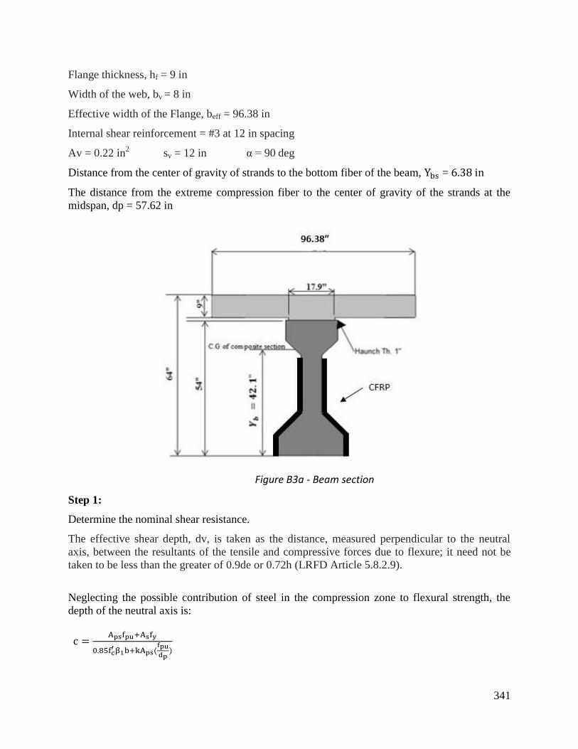
341
Flange thickness, hf = 9 in
Width of the web, bv = 8 in
Effective width of the Flange, beff = 96.38 in
Internal shear reinforcement = #3 at 12 in spacing
Av = 0.22 in2 sv = 12 in α = 90 deg
Distance from the center of gravity of strands to the bottom fiber of the beam, =
The distance from the extreme compression fiber to the center of gravity of the strands at the
midspan, dp = 57.62 in
Figure B3a - Beam section
Step 1:
Determine the nominal shear resistance.
The effective shear depth, dv, is taken as the distance, measured perpendicular to the neutral
axis, between the resultants of the tensile and compressive forces due to flexure; it need not be
taken to be less than the greater of 0.9de or 0.72h (LRFD Article 5.8.2.9).
Neglecting the possible contribution of steel in the compression zone to flexural strength, the
depth of the neutral axis is:

342
The depth of concrete compressive block:
Since a < hf, the stress block is within the flange and the calculation is correct.
= effective depth from the extreme compression fiber to the centroid of the tensile force in the
tension reinforcement =
Check governing case of dv:
dv1 =
dv2 =
dv3 =
dv = max (56.01 , 51.85 , 46.08) = 56.01 in
The nominal shear resistance provided by the concrete, , is calculated in accordance with
LRFD Eqn. 5.8.3.3-3 as:
= 0.0316 β bv dv
For this example, the simplified method is followed (θ = 45 degrees and β=2). However, the
iterative AASHTO LRFD Sectional Method could also be used if desired.
The nominal shear resistance provided by the internal steel reinforcement is :
(LRFD 5.8.3.3-4)
The nominal shear resistance provided by the vertical component of prestressing strands is Vp=0
(this example assumes straight strands; harped or draped strands will have a Vp component).
The nominal shear resistance of the member is:
Step 2:
Check whether strengthening is required.
Strength reduction factor for shear: = 0.9

343
Vn = 112.5 kips < Vu-crit = 150 kips. Therefore, the beam requires strengthening.
Step 3:
Selection of FRP strengthening scheme.
Figure B3b – FRP reinforcement scheme
A 2-sided (non-continuous) configuration is used without an anchorage system. The FRP sheets
will be applied at 90 degrees with respect to the longitudinal axis of the girder. Note that the
following calculation to determine FRP shear resistance for the 2-sided scheme is identical for a
U-wrap scheme.
Assume one layer of FRP is sufficient nf = 1
Width of FRP sheets Wf= 8 inch
Center-to-center spacing of FRP sheets Sf = 12 inch
Orientation of FRP sheets αf = 90 degrees
Effective depth of FRP sheets df = dp - hf
df= 57.62 - 9= 48.62 inch
Check if the selected spacing (12 in) is acceptable: Shear stress in concrete is:
Vu =
=
= 0.38 ksi (LRFD 5.8.2.9-1)
Maximum spacing of FRP strips:
Smax =
0.125 f’c = 0.125 × 5 = 0.63 ksi
Since Vu = 0.38 ksi < 0.63 ksi, Smax = min (0.8 dv , 24)
= min (0.8 × 56.01, 24)= 24 in 12 in < 24 in; the selected spacing is acceptable.

344
Step 4:
Determine FRP shear resistance, Vfrp
The FRP reinforcement ratio is:
=
(AASHTO 4.3.2-2)
=
= 1.083 ×
The FRP strain reduction factor for side bonding or U-wrap without anchorage is:
0.066 ≤ Rf = 3 (ρf × Ef) ≤ 1.0 (AASHTO 4.3.2-5)
= 3 = 0.27
The effective strain εfe =Rf εfu ≤ 0.004
εfe = 0.27 0.0167 = 0.0046
The effective strain is thus taken as 0.004.
Vfrp = ρf Ef εfe bv df (Sin(αf) + Cos (αf)) (AASHTO 4.3.2-1)
Vfrp= 1.083 × × 33000 × 0.004 × 8 × 48.62 (Sin (90) + Cos (90)) = 56 kips
Step 5:
Determine the design shear resistance of the member.
Vn-total = (Vc + Vp + Vs) + frp Vfrp (AASHTO 4.3.1-1)
= 0.9 (63 + 0 + 62) + (0.85 × 56) = 160 kips
Vn-total = 160 kips > Vu-crit = 150 kips. Thus, one layer of FRP is sufficient.
Step 6:
Check maximum FRP shear reinforcement limitations.
Vn ≤ 0.25 f’c bv dv + Vp (AASHTO 5.8.3.3-2)
Vn = Vc + Vs + Vfrp = 63+ 62 + 56 = 181 kips ≤ 0.25 × 5 × 8 × 56.01 + 0 = 560 kips
Thus, the web crushing failure limit is O.K.

345
B4 Shear strengthening of a T-beam using U-Wrap
This example illustrates the shear strengthening of a T-beam with a U-wrap system.
General Properties:
Concrete compressive strength,
Modulus of elasticity = 57 = 57 = 3122 ksi
Factored shear force to resist, Vu = 200 kips
Internal Steel Shear Reinforcement:
Yield strength,
Modulus of elasticity,
FRP Reinforcement:
Thickness, tf = 0.0065 in
Failure strength, ffu = 550 ksi
Modulus of elasticity, Ef = 33000 ksi
Failure strain, εfu = 0.0167 inch/inch
Geometric properties:
Beam height, hT = 48 inch.
Width of the web, 18 inch
Effective flange width, = 54 in
Tensile reinforcement = 10#11, A s = 15.60 in2
Internal shear reinforcement = #4 at 12 in spacing
Av = 0.40 in2 sv = 12 in α = 90⋅deg
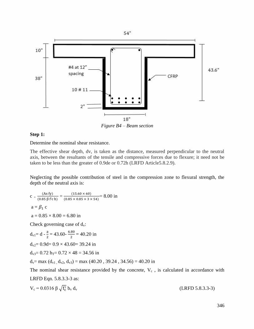
346
Figure B4 – Beam section
Step 1:
Determine the nominal shear resistance.
The effective shear depth, dv, is taken as the distance, measured perpendicular to the neutral
axis, between the resultants of the tensile and compressive forces due to flexure; it need not be
taken to be less than the greater of 0.9de or 0.72h (LRFD Article5.8.2.9).
Neglecting the possible contribution of steel in the compression zone to flexural strength, the
depth of the neutral axis is:
c =
=
= 8.00 in
a = c
a = 0.85 × 8.00 = 6.80 in
Check governing case of dv:
dv1= d -
= 43.60-
= 40.20 in
dv2= 0.9d= 0.9 × 43.60= 39.24 in
dv3= 0.72 hT= 0.72 × 48 = 34.56 in
dv= max (dv1 , dv2, dv3) = max (40.20 , 39.24 , 34.56) = 40.20 in
The nominal shear resistance provided by the concrete, Vc , is calculated in accordance with
LRFD Eqn. 5.8.3.3-3 as:
Vc = 0.0316 β bv dv (LRFD 5.8.3.3-3)

347
For this example, the simplified method is followed: (θ = 45 degree) and (β=2). However, the
iterative AASHTO LRFD Sectional Method could also be used if desired.
The nominal shear resistance provided by the internal steel reinforcement is :
(LRFD 5.8.3.3-4)
The nominal shear resistance provided by the vertical component of prestressing strands is Vp=0
((this example assumes straight strands; harped or draped strands will have a Vp component).
The nominal shear resistance of the member is:
Step 2:
Check whether strengthening is required.
Strength reduction factor for shear = 0.9
Vn = 143 kips < Vu-crit = 200 kips. Therefore, the beam requires strengthening.
Step 3:
Selection of FRP strengthening scheme.
A U-wrap (continuous) configuration is used without an anchorage system at the ends of the
sheets. The FRP sheets will be applied at 90 degrees with respect to the longitudinal axis of the
girder.
Note that the following calculation to determine the FRP shear resistance for the U-Wrap without
anchorage is identical for a side bonding scheme without anchorage.
Assume one layer of FRP is sufficient nf = 1
Orientation of FRP sheets αf = 90 degrees
Effective depth of FRP sheets df = d - hf = 33.60 inch

348
Step 4:
Determine FRP shear resistance, Vfrp
The FRP reinforcement ratio is:
=
(AASHTO 4.3.2-2)
=
= 7.22 × 10
FRP strain reduction factor for U-Wrap without anchorage or side bonding is:
0.088 ≤ Rf = ≤ 1.0 (AASHTO 4.3.2-5)
4 × (7.22 × 10 × 33000) = 0.36
The effective strain εfe = Rf εfu
εfe = 0.36 × 0.0167 = 0.006
Vfrp = ρf Ef εFe bv df (Sin(αf) + Cos (αf)) (AASHTO 4.3.2-1)
Vfrp= 7.22 × 10 × 33000 × 0.006 × 18 × 33.60 (Sin (90) + Cos (90)) = 86 kips
Step 5:
Determine the design shear resistance of the member:
Vn-total = (Vc + Vp + Vs) + frp Vfrp (AASHTO 4.3.1-1)
= 0.9 (79 + 0 + 80) + (0.85 × 86) = 216 kips
Vn-total = 216 kips > Vu-crit = 200 kips. Thus, one layer of FRP is sufficient.
Step 6:
Check maximum FRP shear reinforcement limitations
Vn ≤ 0.25 f’c . bv . dv + Vp (AASHTO 5.8.3.3-2)
Vn = Vc + Vs + Vfrp = 79+ 80 + 86 = 245 kips ≤ 0.25 × 3 × 18 × 40.20 + 0 = 542 kips
Thus, the web crushing failure limit is O.K.

349
B5 Axial Strengthening of a confined circular column
This example illustrates the confinement strengthening of a circular column.
Column properties:
Column height = 24 ft
Column diameter= 28 in
Compressive concrete strength, f ’c = 4 ksi
Spiral spacing= 12 in
Vertical reinforcement, Ast = 12 # 8
Pu = 1800 kips
FRP Reinforcement:
Thickness, tf = 0.013 in
Failure strength, ffu = 550 ksi
Modulus of elasticity, Ef = 33000 ksi
Failure strain, εfu = 0.0167 inch/inch
Tensile strength of a single layer FRP reinforcement at 1.67% strain, Pfrp= 7.14 kips/in/ply
Figure B5 – Column section
Step 1:
Determine the axial strength of the column and check if it requires strengthening.
Ag=
=
= 615 in
2
Pn= 0.85 [0.85 f ’c (Ag- Ast - Aps) + fy Ast - Aps ( fpe – Ep εcu)] (LRFD 5.7.4.4-2)

350
Pn= 0.85 [0.85 × 4 (615- 9.48 - 0) + 60 × 9.48 - 0] = 2233 kips
Pr= Pn = 0.75 × 2233 = 1675 kips (LRFD 5.7.4.4-1)
Pr = 1675 kips < P u= 1800 kips. Therefore, the column requires strengthening.
Step 2:
Compute the FRP reinforcement strength at a strain of 0.004. Note that the limit for confinement
in AASHTO is different from that for flexure (see section 3.4.2.2.2 of this report).
Nfrp=
= 1.71 kip/in
Step 3:
Determine the required confined concrete strength.
Pr = 0.85 [0.85 f’cc (Ag- Ast) + fy Ast] ≥ Pu (AASHTO 5.3.1-1)
From which:
f’cc ≥
–
– =
–
– = 4.38 ksi
f’cc = f’c (1 + 2
) ≥ 4.38 ksi (AASHTO 5.3.2.2-1)
= 4 (1 + 2
) ≥ 4.38, therefore ≥ 0.19 ksi
As per article 5.3.2.2 of AASHTO, the confinement pressure shall be greater or equal to 600 psi
but less than that specified in equation 5.3.3.3-2 as follows:
f = 0.6 ksi ≤
= (
= 1.14 ksi O.K.
Nfrp =
=
= 12.92 ksi/in (AASHTO 5.3.2.2-2)
Required number of plies: n =
=
= 7.56
Try 8 layers. The column axial strength is computed as follows:
f =
= 0.65
= 0.64 ksi
f = 0.64 ≤
= 1.137 ksi O.K.
f’cc = f’c (1 + 2
) = 4 ( 1+ 2
) = 5.28 ksi

351
Pr = 0.85 [ 0.85 f’cc (Ag - Ast) + fy Ast] ≥ Pu
= 0.85 [ 0.85 × 5.28 (615 – 9.48) + 60 × 9.48 ] = 2793 ksi.
Pr= Pn = 0.75 × 2793 = 2095 kips > Pu = 1800 kips.
Thus, the selected number of layers are sufficient.

352
B6 Axial Strengthening of a square column
Column properties:
Column height = 24 ft
Column dimension = 28’’ by 28’’
Compressive concrete strength = 4 ksi
Transverse reinforcement = #3 bars at 12 in
Vertical reinforcement = 12 # 8 bars
Pu= 2100 kips
FRP Reinforcement:
Thickness, tf = 0.013 in
Failure strength, ffu = 550 ksi
Modulus of elasticity, Ef = 33000 ksi
Failure strain, εfu = 0.0167 inch/inch
Figure B6 – Column section
Step 1:
Compute the axial strength of the column.
Pn= 0.80 [0.85 f ’c (Ag- Ast - Aps) + fy Ast - Aps ( fpe – Ep εcu)] (LRFD 5.7.4.4-3)
Pn= 0.80 [0.85 4 (784 - 9.48 - 0) + 60 9.48 - 0] = 2562 kips
Pr= Pn = 0.75 2562 = 1922 kips (LRFD 5.7.4.4-1)

353
Step 2:
Compute the FRP reinforcement strength at a strain of 0.004. Note that the limit for confinement
in AASHTO is different from that for flexure (see section 3.4.2.2.2 of this report).
Nfrp=
= 1.71 kip/in
Step 3:
Compute the required confined concrete strength.
Pr = 0.80 [0.85 f’cc (Ag- Ast) + fy Ast] ≥ Pu (AASHTO 5.3.1-2)
From which:
f ’cc ≥
–
– =
–
– = 4.45 ksi
f’cc = f ’c (1 + 2
) ≥ 4.45 ksi (AASHTO 5.3.2.2-1)
= 4 (1 + 2
) ≥ 4.45, therefore fl ≥ 0.23 ksi
As per article 5.3.2.2 of AASHTO, the confinement pressure shall be greater or equal to 600 psi
but less than that specified in equation 5.3.3.3-2 as follows:
f = 0.60 ksi ≤
= (
) = 1.33 ksi O.K.
Nfrp =
=
= 12.92 kip/ in
Required number of plies: n =
=
= 7.56
Try 8 layers. The column axial strength is computed as follows:
fl =
=
= 0.64 ksi
f’cc = f’c (1 + 2
) = 4 ( 1+ 2
) = 5.27 ksi
Pn = 0.8 [0.85 f’cc (Ag - Ast) + fy Ast] ≥ Pu
= 0.8 [0.85 × 5.27 (784 – 9.48) + 60 ×9.48] = 3231 ksi.
Pr= Pn = 0.75 × 3231= 2423 kips > Pu = 2100 kips
Thus, the selected number of layers are sufficient.

354

355
B7 Axial Strengthening of a confined circular column (ACI procedure)
Column properties:
Column height = 24 ft
Column diameter= 28 in
Compressive concrete strength, f ’c = 4 ksi
Spiral spacing= 12 in
Vertical reinforcement, Ast = 12 # 8
Pu = 1800 kips
FRP Reinforcement:
Thickness, tf = 0.013 in
Failure strength, ffu = 550 ksi
Modulus of elasticity, Ef = 33000 ksi
Failure strain, εfu = 0.0167 inch/inch
Tensile strength of a single layer FRP reinforcement at 1.67% strain, Pfrp= 7.14 kips/in/ply
Figure B7 - Dimensions of the column
Step 1:
Determine the axial strength of the column.
Pn= 0.85 [0.85 f ’c (Ag- Ast) + fy Ast]
Pn= 0.85 [0.85 × 4 (615 – 9.48) + 60 × 9.48] = 2233 kips
Pr= Pn = 0.75 × 2562 = 1675 kips
Pr = 1675 kips < P u= 1800 kips. Therefore, the column requires strengthening.

356
Step 2:
Compute the design FRP material properties.
for CFRP equals 0.85 for exterior exposure (bridges and piers).
= 0.85 550 = 468 ksi
= = 0.85 0.0167 = 0.0142
Step 3:
Determine the required maximum compressive strength of confined concrete, .
=
=
= 4.38 ksi
Step 4:
Determine the maximum confining pressure due to FRP jacket, .
and for circular cross section can be taken as 1.0.
= 0.12 ksi
Step 5:
Determine the required number of plies.
n =
= = 0.55 0.0142 = 0.0078
n =
= 0.50
Try 1 layer.
=
=
= 0.24 ksi
Checking the minimum confinement ratio:
=
= 0.06 which is not equals or greater than 0.08.

357
Thus, try 2 layers:
=
=
= 0.48
=
= 0.12 ≥ 0.08 O.K.
Step 6:
Verify that the ultimate axial strain of the confined concrete, ≤ 0.01.
= (1.5 + 12
(
Where:
=
=
= 0.0019
= (1.5 + 12 (
) = 0.008 < 0.01 O.K.
Step 7:
Determine the column axial strength.
=
= = 5.50 ksi
Pn = 0.8 [0.85 f’cc (Ag - Ast) + fy Ast]
= 0.85 [0.85 × 5.50 (615 – 9.48) + 60 ×9.48] = 2890 kips
Pr= Pn = 0.75 3289 = 2167 kips ≥ 1800 kips
Thus, the selected number of layers are sufficient.
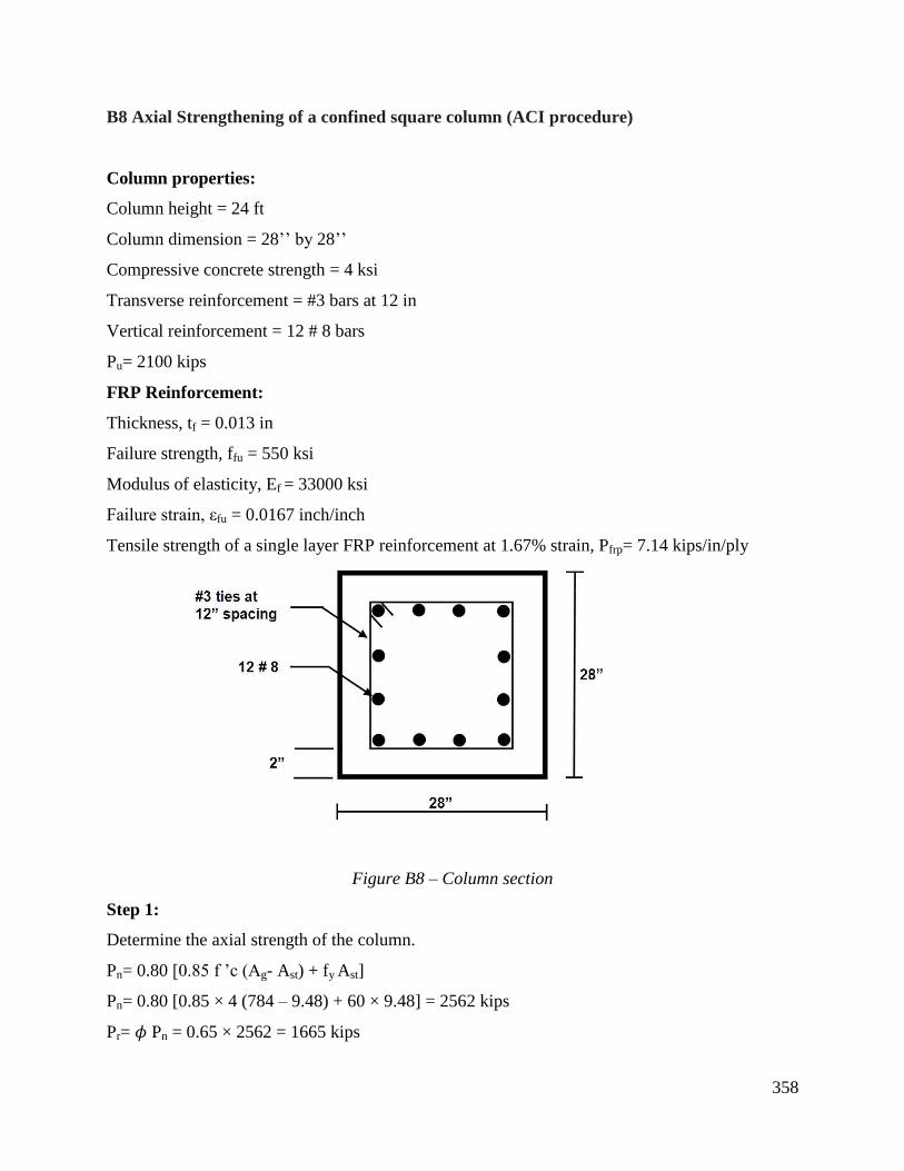
358
B8 Axial Strengthening of a confined square column (ACI procedure)
Column properties:
Column height = 24 ft
Column dimension = 28’’ by 28’’
Compressive concrete strength = 4 ksi
Transverse reinforcement = #3 bars at 12 in
Vertical reinforcement = 12 # 8 bars
Pu= 2100 kips
FRP Reinforcement:
Thickness, tf = 0.013 in
Failure strength, ffu = 550 ksi
Modulus of elasticity, Ef = 33000 ksi
Failure strain, εfu = 0.0167 inch/inch
Tensile strength of a single layer FRP reinforcement at 1.67% strain, Pfrp= 7.14 kips/in/ply
Figure B8 – Column section
Step 1:
Determine the axial strength of the column.
Pn= 0.80 [0.85 f ’c (Ag- Ast) + fy Ast]
Pn= 0.80 [0.85 × 4 (784 – 9.48) + 60 × 9.48] = 2562 kips
Pr= Pn = 0.65 × 2562 = 1665 kips

359
Pr = 1665 kips < P u= 2100 kips. Therefore, the column requires strengthening.
Step 2:
Compute the design FRP material properties.
= 0.85 for exterior exposure (bridges and piers).
= 0.85 550 = 468 ksi
= = 0.85 0.0167 = 0.0142
Step 3:
Determine the required maximum compressive strength of confined concrete, .
=
=
= 5.27 ksi
Step 4:
Determine the maximum confining pressure due to FRP jacket, .
=
=
=
= 0.373
=
=
= 0.373
= 1.09
Step 5:
Determine the required number of plies.
n =
= = 0.55 0.0142 = 0.0078
n =
= 6.45

360
Try 7 layers.
=
=
= 1.18 ksi
Checking the minimum confinement ratio:
=
= 0.295 ≥ 0.08 O.K.
Step 6:
Verify that the ultimate axial strain of the confined concrete, ≤ 0.01.
= (1.5 + 12
(
Where:
=
=
= 0.0019
=
=
= 0.373
= (1.5 + 12 (
) = 0.0076 < 0.01 O.K.
Step 7:
Determine the column axial strength.
=
= = 5.38 ksi
Pn = 0.8 [0.85 f’cc (Ag - Ast) + fy Ast]
= 0.8 [0.85 × 5.38 (784 – 9.48) + 60 ×9.48] = 3289 kips
Pr= Pn = 0.65 3289 = 2137 kips ≥ 2100 kips
Thus, the selected number of layers are sufficient.

361
APPENDIX C: INSPECTION CHECKLIST
General
Are “As-Built” plans being updated to reflect field revisions?
Contractor submittal and training
Has Contractor submitted Quality Control Plan and SDSs?
Has Contractor submitted installing crew qualifications?
Has Contractor submitted documentation of measuring and testing equipment current
calibration?
Are the site staff members properly trained and informed regarding technical inspection and
testing requirements?
Are the site staff members properly trained on emergency and accident procedures?
Materials qualifications/acceptance submittals
Are the following items completed:?
Material properties test results based on a minimum of 10 samples per test.
Fiber properties including tensile strength (determined per ASTM D3039 and not be less that
1%), modulus, and strain.
The mean and coefficient of variation of the moisture equilibrium content, determined per
ASTM D 5229, and are not greater than 2% and 10%, respectively.
Epoxy properties to be evaluated include epoxy tensile strength, modulus, infrared spectrum
analysis, glass transition temperature, gel time, pot life, and adhesive shear strength.
The glass transition temperature is determined per ASTM D4065 and is at least 40oF higher
than the maximum design temperature (see Section 3.12.2.2 of the AASHTO LRFD Bridge
Design Specifications).
After conditioning as specified below, the glass transition temperature and tensile strain, is to
retain 85% of the required values. The conditioning environments are:
Water: Samples are immersed in distilled water having a temperature of 100 ± 3°Fand
tested after 1,000 hours of exposure.
Alternating UV and humidity: Samples are conditioned under Cycle 1-UV exposure per
ASTM G154, and tested within two hours after removal.
Alkali: Samples are immersed in calcium hydroxide (pH ~11) at ambient temperature for
1000 hours prior to testing.
Freeze-thaw: Samples are exposed to 100 repeated cycles of freezing and thawing per
ASTM C666.
If impact tolerance is stipulated by the engineer, it is determined per ASTM D7136.
Daily inspection during installation should include the following test measurements:
Ambient temperature; relative humidity, and general weather observations;

362
Surface temperature of concrete;
Surface dryness per ACI 503.4;
Level of resin curing in accordance with ASTM D2582;
Adhesion strength to exceed 200 psi;
Are the submitted sample results from certified mill analyses and third-party labs?
Have all materials met acceptance requirements?
Have all materials not meeting acceptance requirements properly disposed?
Specific minimum limits required by MDOT are included in Table 1:
(Note: the recommendations in this report do not require any of the specific values given in
Table 1, as long as the values listed above and all design requirements are met)
Table 1 – Strengthening system components minimum properties
Properties Minimum
Values ASTM Test Method
Fiber Fiber tensile modulus 33,000,000 psi D3039
Tensile strain at failure 1.3% D4018
Composite sheet Ultimate tensile strength 3,300 lbs/in D3039
Tensile strain at failure 1.3%
Sheet stiffness 189,000 lbs/in
Resin Tensile strength 9,000 psi D 638
Elongation at break 4.0% D 638
Modulus of elasticity 7 days 390,000 psi D 638
Flexural strength 6,700 psi D 790
Shear strength 14 days 3,500 psi D 732
Deflection temperature 47 C D 648
Water absorption 0.03%
Are the following design parameters clearly listed on the structural engineering submittals for
a non-prestressed beam flexural strengthening project? Note: depending on specific design
application, not all of the following parameters may be needed:
Concrete compressive strength of precast beam,
Modulus of elasticity of concrete,
Reinforcing steel yield strength,
Steel reinforcement area,
Modulus of elasticity of steel,
Internal shear reinforcement and its spacing, FRP
Plate/sheet thickness,
Ultimate tensile strain in the FRP at failure,
Tensile strength in the FRP at ultimate strain,
Glass transition temperature,
Shear modulus of the adhesive,
Modulus of elasticity of fiber,
Total height of beam including deck slab,
Flange thickness,
Effective width of the flange,
Bridge span length,
Distance from extreme comp. fiber to steel centroid,
New nominal loads for fatigue limit state,
Shear force at reinforcement end-termination,
New load capacity needed

363
In the case of prestressed concrete beam designed for flexural strengthening, the following
parameters may be added to the above list:
Concrete compressive strength of the deck,
Area of prestress tendons,
Diameter of tendons,
Initial pre-tensioning at service limit state,
Yield strength,
Ultimate stress,
Type of strands,
Dist. from extreme comp. fiber to strand centroid.
When designing for shear strengthening of a nonprestressed member, the following
parameters may be needed:
Concrete compressive strength of precast beam,
Modulus of elasticity of concrete,
Reinforcing steel yield strength,
Steel reinforcement area,
Modulus of elasticity of steel,
Internal shear reinforcement and its spacing,
FRP plate/sheet thickness,
Ultimate tensile strain in the FRP at failure,
Tensile strength in the FRP at ultimate strain,
Modulus of elasticity of FRP,
Tensile strength of FRP at ultimate strain,
Orientation of FRP sheets,
Width of FRP sheets,
Center-to-center spacing of FRP sheets,
Total height of beam including deck slab,
Flange thickness,
Effective width of the Flange,
Bridge span length,
Dist. from extreme comp. fiber to steel centroid,
Effective depth of FRP sheets,
Width of the web,
New shear capacity needed
When designing for shear strengthening of a prestressed member, the following parameters
may be added to the above list:
Concrete compressive strength of the deck,
Area of prestress tendons,
Diameter of tendons,
Initial pre-tensioning at service limit state,
Yield strength of tendons,
Ultimate stress of tendons,
Type of strands,
Effective depth from extreme comp. fiber to
centroid of reinforcement.
Design parameters required for column wrapping (confinement) include:
Concrete compressive strength,
Reinforcing steel yield strength,
Steel reinforcement area,
Tie or spiral spacing,
Area of strands,
Initial pre-tensioning at service limit state,
Modulus of elasticity of strands,
FRP sheet thickness,
Ultimate tensile strain of the FRP
Modulus of elasticity of FRP
Tensile strength of FRP at ultimate strain,
Column geometry,
Column height,
Ultimate axial load to resist.

364
FRP Shipping, storage, and handling
Do packages received include SDS?
Were packages inspected upon delivery for damage?
Are FRP systems stored in accordance with manufacturer’s guidelines?
Are catalysts and initiators stored separately?
Are chemical components securely sealed per OSHA?
Are flammable resins stored in accordance with fire regulations?
Are expired materials disposed of in accordance with environmental control regulations?
Are hazardous materials such as thermosetting resins properly labeled?
Are SDSs accessible to all at project site? Are they read and understood by personnel
handling hazardous materials?
Is proper gear (suits, gloves, dust masks, respirators, etc.) available for handling resins,
solvents and fiber materials?
Is the resin mixing area well ventilated?
Are waste materials disposed in accordance with environmental regulations?
Removal and restoration of defective surfaces prior to concrete placement
Have the perimeters of existing spalls been identified and saw cut to a minimum depth of
0.75 in to prevent feathered edges?
Are cracks within concrete greater than 0.01 in spaced closer than 1.5 in, and cracks wider
than 1/32 in epoxy injected?
After removal of all defective areas, did Contractor inspect and clean the substrate from any
dust, laitance, grease, oil, curing compounds, wax, impregnations, foreign particles and other
bond-inhibiting materials?
Has all exposed steel been sandblasted clean prior to concrete placement?
Did the Contractor apply a bonding and reinforcement protection to all exposed
reinforcement and concrete surface prior to concrete placement?
Inspection of surface preparation prior to FRP application
Have all inside and outside corners and sharp edges been rounded or chamfered to a
minimum radius of 1/2 in?
Is restored concrete surface smooth and uniform with a maximum out of plane deviation <
1/32 in?
Are all voids with diameters larger than 1/2 in and depressions greater than 1/16 in filled and
cured?
Have all cracks in the concrete wider than 0.01 in spaced closer than 1.5 in and cracks wider
than 1/32 in been filled using pressure injection of epoxy?
Was the surface checked and cleaned of any dust, laitance, grease, oil, curing compounds,
wax, impregnations, surface lubricants, paint coatings, stains, foreign particles, weathered
layers and any other bond-inhibiting materials?

365
Has the substrate concrete compressive strength checked to be 2.2 ksi or greater, and tensile
strength to be 220 psi or greater?
Application conditions
Is the ambient temperature and temperature of concrete surface within the range of 50°F-
90°F?
Are the contact surfaces completely dry at the time of installation of FRP system?
Does the weather forecast predict dry conditions or potential rain? If rain is imminent, stop
application till dry conditions are assured.
Installation of wet lay-up systems
Are field data including temperature, surface condition, and relevant field observations being
documented?
Are witness panels prepared with a size of at least 300 – 775 in2, but not less than 0.5% of the
overall area to be strengthened?
Is the resin mixed in quantities sufficiently small to ensure its use within manufacturer
recommended pot life?
Is the excess resin disposed of when exceeded its pot life, or when it begans to generate heat
or show signs of increased viscosity?
Are the ambient and concrete surface temperatures as specified in the contract drawings and
recommended by the manufacturer?
Is the excess primer disposed of when it exceeds its pot life?
Is the putty, if necessary, applied as soon as the primer becomes tack-free or until non-sticky
to the fingers?
Are the surfaces of primer and putty protected from dust, moisture and other contaminants
before applying the FRP system?
Is the fiber sheet placed properly and pressed gently onto the wet saturant?
Is any entrapped air between fiber sheet and concrete released?
Is rolling conducted in the fiber direction for unidirectional fiber sheets?
Is sufficient saturant applied on top of the fiber sheet as overcoat to fully saturate the fibers?
Are lap splice lengths as specified in the contract drawings, but at least 8 in?
Is there any deviation in fiber alignment more than 5°?
Is the FRP system protected as necessary until it is fully cured?
Identification of defective work
Are voids or air encapsulation (pockets) found between the concrete and the layers of primer,
resin and/or adhesive, and within the composite itself? (per existing MDOT guidelines, voids
with a size of 0.25 – 2.5 in2 must be repaired).
Are delaminations larger than 2 in2 (1300 mm
2) detected (using acoustic sounding,
ultrasonic, or thermography)? If more than 10 such delaminations were detected in 10 ft2,
were they repaired?

366
Are there any wrinkling or buckling of fiber, fiber tows, or discontinuities due to fracture of
the fibers?
Are there any resin-starved areas or areas with non-uniform impregnation/wet-out?
Are there any cracks, blisters or peeling of the surface coating?
Is there any under-cured or incompletely cured polymer?
Are there any incorrectly placed reinforcement configurations?
Post-installation quality control tests
Were the following QC tests completed?:
Perform surface inspection for any swelling, bubbles, voids or delaminations after at least 24
hours of initial resin cure. If advanced equipment is unavailable, perform an acoustic tap test
with a hard object to identify delaminated areas by sound. Mark all voids and assess the size
of each to determine if repair is needed.
Perform direct pull-off test according to ASTM D4541, ASTM D7234, or the method
described by ACI 440.3R (2004), Test Method L.1. Successful tension adhesion strengths
should exceed the greatest of 200 psi or 0.065 ksi, and exhibit failure of the concrete
substrate.
Repair areas after bonding tests according to the procedures established in the contract
drawings and specifications.
Long-term maintenance inspections
Were the following inspections completed?:
An annual general inspection, primarily visual in nature. In the annual inspection, the
inspector looks for changes in color, signs of crazing, cracking, delamination/debonding,
peeling, blistering, deflection, or evidence of other deterioration, in addition to local damage
due to impact or surface abrasion.
A detailed inspection at least once every 6 years, where the inspection attempts to more
accurately quantify the performance and condition of the FRP system. Pull-off testing and
test evaluation for debonding and FRP degradation are performed as part of detailed testing.

367
APPENDIX D: MODIFICATIONS TO EXISTING MDOT SPECIFICATIONS
The following text provides recommended changes to the MDOT Special Provisions for FRP
Flexural and Shear Strengthening Systems and Column Wrapping. The recommendations that
follow are not meant to be a specification. Rather, the purpose is to identify conflicts, if any,
between the existing provisions and the recommendations presented in Chapter 8 of this report,
as well as to fill any gaps in the existing provisions that may be addressed in this report. Issues
in the existing specifications that are not directly addressed or contradicted by the
recommendations of Chapter 8 are not altered.
Therefore, the first recommendation that applies to all existing documents is to incorporate the
recommendations of Chapter 8. As inspection is not discussed in detail in the provisions,
Chapter 8.2.4 of the report may be particularly useful. Some specific points are provided below.
D.1 MDOT Special Provision for Column Wrapping with FRP Sheets
1) Article b.1 (page 2): Revise as follows (refer to Report Section 8.2.1.1 for additional
detail): List of all materials and manufacturers, with material safety data sheets and
shipping, storage and handling requirements.
2) Article b.8 (page 2): Add the following (see Report Sections 8.2.4.1 and 8.2.5): The
contractor (installer) is required to submit a QA/QC plan. Manufacturer and contractor
qualifications are to be verified in accordance with the provisions in NCHRP Report 609.
3) Article c. (page 2). Revise as follows: Apply FRP to the columns shown on the plans, in
accordance to the number of layers specified. Each individual layer of FRP must meet
the material requirements.
4) Article c (page 3): The construction details provided can be supplemented by the
description in Section 8.2.3 of the Report, especially with Article 8.2.3.1.
5) Article c (page 3): Replace the clause: “Repair delaminations larger than 0.25 square
inches” with the Report recommendation in Section 8.2.5.4, which states the following:
For wet layup systems, the need for delamination repair depends on the size and number
of delaminations. Small delaminations less than 2 in2 (1300 mm
2) are permissible as
long as the delaminated area is less than 5% of the total laminate area and there are no
more than 10 such delaminations per 10 ft2 (1 m
2). Delaminations exceeding these limits
are to be repaired by either resin injection or ply replacement, depending on
delamination size. Large delaminations, greater than 25 in2 (16,000 mm
2), should be
repaired by selectively cutting away the affected sheet and applying an overlapping sheet
patch of equivalent plies with appropriate overlap length. Delaminations less than 25 in2
(16,000 mm2) may be repaired by either resin injection or ply replacement.
368
D.2 MDOT Special Provision for FRP Flexural Strengthening System
1) Repeat numbers (1); (2); (4); (5) from Section D.1.
2) Additional detail on pull-off testing and required minimums are provided in Section
8.2.5.1 of the report.
D.3 MDOT Special Provision for FRP Shear Strengthening System
1) Repeat numbers (1); (2); (4); (5) from Section D.1.
2) Article c (page 2): The first paragraph states a maximum gap of one inch between FRP
shear strips is allowed. This is in contradiction to the recommended AASHTO FRP
design provisions, which are as follows:
where dv is the effective shear depth (in) and vu the shear stress (ksi), as defined in
AASHTO LRFD section 5.8.2.9.