Range of Products - Pantron Sensor Technology - Sensors ... · KFS KKF TKFD MKF INR IF 5 clean air...
24
clean air solutions Range of Products Filter Systems and Accessories
Transcript of Range of Products - Pantron Sensor Technology - Sensors ... · KFS KKF TKFD MKF INR IF 5 clean air...

c l ea n a
i r s o l u
t i on s
Range of ProductsFilter Systems and Accessories

2 KKF TKFD MKF INR IF INR20 TKFVA MKFVA INRVA IFVA
c l e a n a i r s o l u t i o n s
KFS
Extraction unit A B C D
KFS 30–80 230/50–60 100 250x250x400
A Air Volume max. (m³/h)B Power Input (kW)
C Engine power (W)D Dimensions (mm)
KFS
KFS – the little one with the big performance
• very compact and integrable into machinery equipment
• high quality suction fan for conti-nuous operation
• automatic filter monitoring via differential pressure
• suitable for 19“ rack mounting
Applications:
•Small welding and marking lasers
•Soldering fumes•Adhesive vapours
3KFS KKF TKFD MKF INR IF INR20 TKFVA MKFVA INRVA IFVA
c l e a n a i r s o l u t i o n sKKF
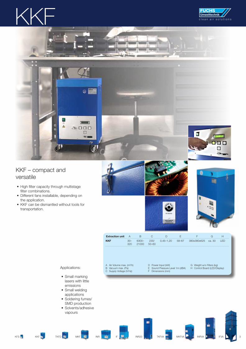
KKF – compact and versatile
•High filter capacity through multistage filter combinations.
•Different fans installable, depending on the application.
•KKF can be dismantled without tools for transportation.
Applications:
•Small marking lasers with little emissions
•Small welding applications
•Soldering fumes/SMD production
•Solvents/adhesive vapours
Extraction unit A B C D E F G H
KKF 30– 6300– 230/ 0,45–1,20 58–67 380x380x625 ca. 30 LED 320 21000 50–60
A Air Volume max. (m³/h)B Vacuum max. (Pa)C Supply Voltage (V/Hz)
D Power Input (kW)E Sound Pressure Level 1m (dBA)F Dimensions (mm)
G Weight w/o Filters (kg)H Control Board (LED/Display)

4 KFS KKF TKFD MKF INR IF INR20 TKFVA MKFVA INRVA IFVA
TKFD
TKFD – comparable performance as the MKF but even more compact
•High filter capacity through integrated preli-minary separator.
• Ideal in confined spaces - installable under work tops or integratable in machines.
Applications:
•Marking lasers•Small welding
applications•Small laser
trimming (foils, synthetic material)
•Soldering fumes/SMD production
• Fine particles/fumes•Solvents/adhesive
vapours
Extraction unit A B C D E F G H
TKFD 30– 6300– 230/50–60 0,45–1,20 56–67 490x380x620 ca. 30 LED/ 335 21000 Display
A Air Volume max. (m³/h)B Vacuum max. (Pa)C Supply Voltage (V/Hz)
D Power Input (kW)E Sound Pressure Level 1m (dBA)F Dimensions (mm)
G Weight w/o Filters (kg)H Control Board (LED/Display)
c l e a n a i r s o l u t i o n s

5KFS KKF TKFD MKF INR IF
c l e a n a i r s o l u t i o n s
INR20 TKFVA MKFVA INRVA IFVA
MKF – the classic filter unit from the Fuchs Umwelttechnik range
•Compact and versatile.•High filter capacity through multistage
filter combinations.•Different fans installable, depending on
the application.•MKF can be dismantled without tools
for transportation.
Applications:
•Marking lasers •Welding/Cutting
applications•Soldering fumes/multi-
ple workplaces• Fine particles/fumes•Solvent vapours
MKF
Extraction unit A B C D E F G H
MKF 30– 3600– 230/50–60 0,40–1,30 57–67 660x380x825 ca. 32 LED/ 625 21000 Display
A Air Volume max. (m³/h)B Vacuum max. (Pa)C Supply Voltage (V/Hz)
D Power Input (kW)E Sound Pressure Level 1m (dBA)F Dimensions (mm)
G Weight w/o Filters (kg)H Control Board (LED/Display)

6 KFS KKF TKFD MKF INR IF INR20 TKFVA MKFVA INRVA IFVA
TKFVA
TKFVA – preliminary separator in a compact size
• For the preliminary separation of large dust volumes.
•Extremely compact.•High filter capacity, additional capacity rapid-
ly implementable if required.•Special clamping system optimises seal
tightness.•Operator and maintenance friendly
Applications:
•Small welding, cutting and marking lasers
• for dry fumes from metal processing
Extraction unit A B C D E F H
TKFVA103 280 7700 230/50–60 0,55 62 750x400x1205 LED
TKFVA108 200 21000 230/50–60 0,95 62 750x400x1205 LED
A Air Volume max. (m³/h)B Vacuum max. (Pa)C Supply Voltage (V/Hz)
D Power Input (kW)E Sound Pressure Level 1m (dBA)F Dimensions (mm)
G Weight w/o Filters (kg)H Control Board (LED/Display)
c l e a n a i r s o l u t i o n s

7KFS KKF TKFD MKF INR IF
c l e a n a i r s o l u t i o n s
INR20 TKFVA MKFVA INRVA IFVA
MKFVA – no dust, no fumes – the midsize preliminary separator
• For the preliminary separation of large dust volumes.
•Compact dimensions.•High filter capacity, additional capacity easily
implementable if required.•Special clamping system optimises seal
tightness.•Operator and maintenance friendly
MKFVA
Applications:
•Welding lasers•Cutting lasers•Central extraction
Extraction unit A B C D E F H
MKFVA102 415 11000 230/50–60 1,30 65 700x660x1450 LED
MKFVA103 320 12500 230/50–60 1,20 64 700x660x1450 LED
MKFVA08 450 660x550x1560 Display
MKFVA10/11 450 660x550x1560 Display
A Air Volume max. (m³/h)B Vacuum max. (Pa)C Supply Voltage (V/Hz)
D Power Input (kW)E Sound Pressure Level 1m (dBA)F Dimensions (mm)
G Weight w/o Filters (kg)H Control Board (LED/Display)

8 KFS KKF TKFD MKF INR IF INR20 TKFVA MKFVA INRVA IFVA
INR – the large filter capacity is achieved by a multistage filter combination
•With integrated preliminary separator.•Also designed to handle oil or emulsion
mist.•Different fans are possible depending on
the application.• INR can be easily installed anywhere
since the filtered air remains in the room – this dispenses with installation of waste air ducts, minimises costs and increases health safety and environmental protec-tion.
• INR can be dismantled without tools for transportation.
INR
Applications:
•Marking and engraving lasers
•Cutting and welding lasers
•Soldering and weld-ing fumes
• Fine particles/fumes•Solvents and adhe-
sive vapours•Oil mist, emulsion
mist
Extraction unit A B C D E F H
INRTW270 100–320 12500 230/50–60 1,20 59 680x590x970 Display
INRTW540 100–640 12500 230/50–60 2,40 65 680x590x970 Display
INRM0810 810 2200 400V/50 0,55 58 680x590x970 Display
A Air Volume max. (m³/h)B Vacuum max. (Pa)C Supply Voltage (V/Hz)
D Power Input (kW)E Sound Pressure Level 1m (dBA)F Dimensions (mm)
G Weight w/o Filters (kg)H Control Board (LED/Display)
c l e a n a i r s o l u t i o n sc l e a n a i r s o l u t i o n s

9KFS KKF TKFD MKF INR IF
c l e a n a i r s o l u t i o n s
INR20 TKFVA MKFVA INRVA IFVA
IF – for 1, 2 or more extraction points
•Very low noise.•Suitable for one or several extraction
points.•Different fans are possible depending on
the application.• The very large filter capacity is achieved
by a multistage filter combination.•Range of different air flow rates.• The filtered air can be recirculated in the
room – this dispenses with installation of waste air ducts, minimises costs and increases health safety and environmen-tal protection.
• Ideal for the rapid equipping of existing workplaces.
IF
Applications:
•Marking and engraving lasers
•Cutting and welding lasers
•Soldering and welding fumes
• Fine particles and fumes
•Solvents and adhe-sive vapours
•Oil mist, emulsion mist
Extraction unit A B C D E F G H
IF 1 1450 2230 400/50 1,10 65 950x670x1450 120 Display
IF 2 1700 2910 400/50 1,50 68 950x670x1450 125 Display
IF 3 2200 3000 400/50 1,50 70 950x670x1450 130 Display
A Air Volume max. (m³/h)B Vacuum max. (Pa)C Supply Voltage (V/Hz)
D Power Input (kW)E Sound Pressure Level 1m (dBA)F Dimensions (mm)
G Weight w/o Filters (kg)H Control Board (LED/Display)

10 KFS KKF TKFD MKF INR IF INR20 TKFVA MKFVA INRVA IFVA
INR20 – for mobile or stationary applications
•Very low noise.•With integrated preliminary separation
system.•Also designed to handle oil or emulsion
mist.•Different air flow rates.•Very high quality standard, not only for
sporadic applications but also for conti-nuous duty.
• The filtered air can be recirculated in the room – this dispenses with installation of waste air ducts, minimises costs and increases health safety and environmen-tal protection.
•Highly suitable for one or several extrac-tion points.
INR20
Applications:
•Marking and engraving lasers
•Cutting and welding lasers
•Soldering and welding fumes
• Fine particles; fumes•Solvents and adhe-
sive vapours•Oil mist, emulsion
mist
Extraction unit A B C D E F G H
INR20260 100–320 12500 230/50–60 1,20 58 660x670x2100 120 Display
INR20810 810 2200 400/50 0,55 58 660x670x2100 135 Display
INR20540 540 14000 400/50 2,60 62 660x670x2100 130 Display
INR22200 2220 3000 400/50 1,50 68 660x670x2100 145 Display
INR21700 1700 2910 400/50 1,10 58 660x670x2100 138 Display
INR21380 100–1500 5000 400/50 2,20 70 660x670x2100 142 Display
INR20690 100–1000 5100 400/50 1,10 62 660x670x2100 135 Display
INR20520 100–640 12500 230/50–60 2,40 60 660x670x2100 126 Display
INR20830 100–830 11000 230/50–60 2,60 62 660x670x2100 126 Display
A Air Volume max. (m³/h)B Vacuum max. (Pa)C Supply Voltage (V/Hz)
D Power Input (kW)E Sound Pressure Level 1m (dBA)F Dimensions (mm)
G Weight w/o Filters (kg)H Control Board (LED/Display)
c l e a n a i r s o l u t i o n s

11KFS KKF TKFD MKF INR IF
c l e a n a i r s o l u t i o n s
INR20 TKFVA MKFVA INRVA IFVA
INRVA – the XL-size preliminary separator
• For the preliminary separation of extra large dust volumes.
•Compact dimensions.•High filter capacity, additional capacity
easily implementable if required.•Special clamping system optimises seal
tightness.•Operator and maintenance friendly
INRVA
Applications:
•Dust separation•Cutting and welding
lasers•Welding fumes
Extraction unit A B C D E F H
INRVA05 1680 16000 400V/50 1,2 67 900x660x2220 Display oder 230/50–60 – 4,0
INRVA10 2500 12500 400V/50 1,2 70 1200x660x2500 Display oder 230/50–60 – 7,5
A Air Volume max. (m³/h)B Vacuum max. (Pa)C Supply Voltage (V/Hz)
D Power Input (kW)E Sound Pressure Level 1m (dBA)F Dimensions (mm)
G Weight w/o Filters (kg)H Control Board (LED/Display)

12 KFS KKF TKFD MKF INR IF INR20 TKFVA MKFVA INRVA IFVA
IFVA – the big XXL-size preliminary separator
• For the preliminary separation of very large dust volumes.
•High efficiency despite compact dimen-sions.
•High filter capacity, easy to expand with additional capacity.
•Special clamping system optimises seal tightness.
•Operator and maintenance friendly
IFVA
Extraction unit A B C D E F H
IFVA 2800 8600 400V/50 2,2 69 1480x950x3900 Display oder 230/50–60 – 5,0
A Air Volume max. (m³/h)B Vacuum max. (Pa)C Supply Voltage (V/Hz)
D Power Input (kW)E Sound Pressure Level 1m (dBA)F Dimensions (mm)
G Weight w/o Filters (kg)H Control Board (LED/Display)
Applications:
•Dust separation•Cutting and welding
lasers•Welding fumes
c l e a n a i r s o l u t i o n s

13
c l e a n a i r s o l u t i o n sThe Coanda Effekt
The extractor tip must be positioned as close to the sur-face as possible.
The Coanda Effekt
When the extractor opening is positioned close to a flat sur-face, it has a limited capacity to extract excess room air that is unsoiled by fumes or vapor. As a result, a vacuum builds up be-tween the surface and the extracted air. This is why the air tries to “adhere“ to the surface. This is a type of ejector effect which is called the Coanda or adhesion effect. The distance between the place where soiling takes place and the extractionshield can be lengthened by utilizing this effect.
c l e a n a i r s o l u t i o n s

14
Suction Nozzles
MKF RSDF MKF RSDR
MKF SD35
MKF SD15
MKF SD 20
Effective extraction needs suitable collection
•precisely accurate, central, wide or as extraction cabinet
• sophisticated aero dynamics and optimal flow combined with simulation software are essential for developing perfect collection systems
• extraction nozzles, extraction unit and extraction power need to be harmonized
c l e a n a i r s o l u t i o n s

15
c l e a n a i r s o l u t i o n s
MKF MH 300
c l e a n a i r s o l u t i o n sExtraction Accessories
MKF SD10
MKF AB
MKF TR
MKF AH
MKF RDMKF TK
Extraction arm diam. 50 or 75 for wall mounting
Transparent pipe with slid MKF ARR
AS AH
MKF APL1

16
REGULATIONS, RULES AND MEASURES
The Hazardous Substances Ordinance (GefStoffV), basic legislative framework
Duty to investigateAccording to section16, the employer must perform investigations to ascertain if hazardous substances are present in the work-place. Welding fumes, soldering fumes and fumes arising fromlaser use must always be considered to be hazardous, the same applying to solvent vapours and vapours released by plastics.General duty of protectionThe “general duty of protection” referred to in section17 is the le-gal duty of the employer to take the necessary measures to meet currently valid health and safety regulations in the workplace.Duty to monitorThere is no completely reliable way of preventing the release of one or more hazardous substances into the air at the workplace when welding, cutting and related procedures are being per-formed; this also applies to laser emissions, solder fumes and solvent vapours.
Section 18 “Duty to monitor” requires the employer to determine whether concentrations are below the MAK (maximum workplace concentration) or the TRK (technical guide concentration) or whether the trigger threshold has been exceeded.Priority of safety measuresSection 19 “Priority of safety measures”, after taking into account the state of the art for the measures to reduce or eliminate haz-ards, gives the following priorities:• Work-process design to prevent the release
of hazardous substances• Detection of hazardous substances in the areas
where they arise• Ventilation measures• Personal safety equipment
Regulations relating to recycled air
General requirementsSection 4 Ventilation equipment, par. 2 of UVV VBG 15 states: Extracted air may only be returned to work and traffic areas after adequate removal of substances that are hazardous to health.According to the instructions that specify how this requirement is to be implemented, “adequate removal” is defined to be a con-centration that does not exceed ¼ of the MAK.
Recycled air in relation to carcinogens and other emissionsIf welding fumes contain carcinogenic components, say, nickel compounds or chromates, and it is not possible to release ex-haust air directly into the open air for operational reasons, therequirements stated in TRGS560 “Technical regulations relating
to hazardous substances – recycled air containing carcinogens” must be fully complied with. Consequently, the concentration ofhazardous substances in the recycled, cleaned air shall not ex-ceed a tenth of the TRK.Tips on implementationOperators can use both mobile dust removers and systems under central control to comply with regulations.Only a regime of regular checks can ensure that extraction sys-tems for hazardous substances are operating effectively in the long term. Factory legislation stipulates annual inspection by anauthorised inspector which must be documented in a log book.The legislative basis for the approval authority for waste air extraction
Information c l e a n a i r s o l u t i o n s

17
c l e a n a i r s o l u t i o n sInformation
Terminology
MAK value(maximum workplace concentration)The purpose of MAK values is to safeguard the health of workers at the workplace. They are defined as the maximum permissible concentration of a substance (gas, vapour or suspension) that will not lead to health impairments in the long-term.TRK value(technical guide concentration)The Committee on Hazardous Substances instituted by the Federal Ministry for Employment and Social Security specifies TRK values for carcinogens and suspected carcinogens for which no MAK value exists. The risk of impairments to health is reduced by observing TRK-values, but does not mean that no health risk exists. MAK and TRK values are listed in TRGS 900 and are re-issued annually. MAK and TRK values are referred to as “air limits”.Trigger thresholdThe trigger threshold is exceeded, if it cannot be demonstrated that the air limit is met. In the case of split air limits, the lower value applies, if special stipulations have not been made (TRGS 101). If the trigger threshold has been exceeded, additional
measures must be taken to safeguard health, e.g. medical exami-nation at the workplace (GefStoffV and UVV VBG 100).).
Extracting hazardous substances directly at the point of origin and efficiently filtering themwith our compact filter devices.As our extraction systems are precisely tailored to requirements, effective hazardous substance removal is possibleTechnical and economic advantages:• Smaller pipe diameters and short pipe lengths mean minimal
installation costs• Compact ventilators and filter technology• Detection elements can be individually configured and are
easy to handle• Hazardous substances are eliminated well before they can
be inhaled by the user.• Great acceptance by users ensures a high level of effective-
ness• Minimal costs resulting from reduced intake of fresh air
(reduction in heating costs)
German federal immissions legislation
Technical Instructions on Air Quality Control (TA-Luft)
According to section 22 “Duties of the operators of systems which do not require approval” in the Federal Immissions Law, harmful environmental effects which can be avoided by state-of-the-art easures must be prevented and if they cannot be elimi-nated, they must be minimised as far as possible.The technical instructions on air quality (TA-Luft) can be used to determine the state of the art. In this context, the main require-ments of TA-Luft are:
Total dustEmissions in the form of dust in waste gas shall not exceed a concentration of 0.05 g/m³• at a mass flow rate greater than 500 g/h nor a concentration
of 0.15 g/m³ • at a mass flow rate less than or equal to 500 g/h.
Inorganic substances in dust formThe inorganic substances in dust form referred to below shall in total not exceed the following waste air concentrations by mass even if several substances from the same class or classes II and III are present:Class II:Cobalt and its compounds, indicated by “Co”, nickel and its com-
pounds, indicated by “Ni”, at a• mass flow rate of 5 g/h or more than 0.001 g/m³Class III:Chromium and its compounds, indicated by “Cr”, at a• mass flow rate of 25 g/h or more than 0.005 g/m³
Hazard assessmentTechnical directive on hazardous substances (TRGS)If it is not possible to guarantee the absence of hazardous sub-stances at MAK or TRK levels in the workplace, then, according to TRGS 402 “Determination and assessment of concentrations of hazardous substances in the air at the workplace”, the con-centration of the hazardous substances must be determined and assessed. This is done by means of workplace analyses and, if necessary, by control measurements.Data on the time and space distribution of the hazardous subs-tances is used to determine whether the limits have been met. This information is derived from measurements in the workplace or from reliable calculations. The following can be used to obtain this information:• Results already obtained from one’s own measurements or
empirical data from third parties• Measurement results obtained from comparable systems or
activities• Reliable calculations

18
FILTER TECHNOLOGY FOR LASER EMISSIONS –TESTED BY THE HANNOVER LASER CENTRE
The company Fuchs Umwelttechnik GmbH has set itself the task of continuously investing in the further devel-opment of extraction and filter technology. This means that our filtering equipment is constantly being further
developed and improved in all areas. It also means that filtering equipment which has been further developed must be put to the test again and again in order to ensure that it fulfils the legally stipulated safety and quality requirements. These are the criteria we set ourselves!
For this reason, Fuchs Umwelttechnik has its equipment regu-larly tested by the Hannover Laser Centre. These series of tests are designed to show how high the separation power of Fuchs Umwelttechnik filtering equipment is. After all, this separation power, specific to the filtering equipment, is the guarantee that the filtering equipment is safe to use in all situations specified.
The filtering equipment and high-quality filter technology must suit each other. This means that the filters inserted into the equipment must fit precisely and sit tightly in the housing to prevent leakages. If this is not the case, the result can be disastrous: the pollut-
ants, which should actually be filtered out, will leak out into the exhaust air. This is very dangerous because the pollutant danger is concealed. In such cases, however, the service life of the filters used is very high – considerably higher than in “leak-proof” filter/housing combinations. A false saving!
The following summary shows the separation power of Fuchs Umwelttechnik filtering equipment.
The laser was chosen as the emission source because the emissions caused by inscription, welding or cutting lasers, for example, are composed of very fine particles and gases.
Plastic foils and chrome nickel metal were treated by the laser. The resulting emissions were extracted and filtered by our equip-ment.
All the tests are practice-oriented, i.e. inscribing, removing and cutting were the methods used. In the following pages, you can learn about the impressive results of these tests.
1. Inscribing acrylate foil by laser beam
Filter MKF 103 in combination with pre-separation system MKFVA 10
Summary of the results
The tests conducted to determine the features of the emissions caused by inscribing acrylate foil material by means of laser beams show a wide range of different emission components. Apart fromthe numerous substances with different chemical and physical fea-tures, the fineness of the resulting particle emissions places heavy demands on the filter technology.
The filter MKF 103 / MKFVA 10 from Fuchs Umwelttechnik GmbH was used to separate the emissions caused when acrylate foil is inscribed by laser. The filtration efficiency
achieved by this filter on the acrylate foil not only meets all statutory requirements and limits but also exceeds them by a considerable margin.
The tests on the loss of pressure caused when high particle ele-ments are separated, show that the filter elements used achieve a high separation power. However, the strongly adhesive features of the particle emissions caused by the laser treatment of plastic ma-terials, in combination with the fine-grained nature of the particles, lead to a constant, almost linear rise in the loss of pressure.
Information c l e a n a i r s o l u t i o n s
19
c l e a n a i r s o l u t i o n s
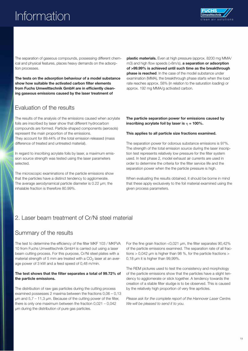
The separation of gaseous compounds, possessing different chem-ical and physical features, places heavy demands on the adsorp-tion processes.
The tests on the adsorption behaviour of a model substance show how suitable the activated carbon filter elements from Fuchs Umwelttechnik GmbH are in efficiently clean-ing gaseous emissions caused by the laser treatment of
plastic materials. Even at high pressure (approx. 8200 mg MMA/m3) and high flow speeds (>8m/s), a separation or adsorption of >99.99% is achieved until such time as the breakthrough phase is reached. In the case of the model substance under examination (MMA), the breakthrough phase starts when the load rate reaches approx. 58% (in relation to the saturation loading) or approx. 192 mg MMA/g activated carbon.
Evaluation of the results
The results of the analysis of the emissions caused when acrylate foils are inscribed by laser show that different hydrocarbon compounds are formed. Particle-shaped components (aerosols) represent the main proportion of the emissions. They account for 89.44% of the total emission released (mass difference of treated and untreated material).
In regard to inscribing acrylate foils by laser, a maximum emis- sion source strength was tested using the laser parameters selected.
The microscopic examinations of the particle emissions show that the particles have a distinct tendency to agglomerate. The average aerodynamical particle diameter is 0.22 μm; the inhalable fraction is therefore 80.99%.
The particle separation power for emissions caused by inscribing acrylate foil by laser is η = 100%.
This applies to all particle size fractions examined.
The separation power for odorous substance emissions is 97%.The strength of the total emission source during the laser inscrip-tion test represents relatively low pressure for the filter system used. In test phase 2, model exhaust air currents are used in order to determine the criteria for the filter service life and the separation power when the the particle pressure is high.
When evaluating the results obtained, it should be borne in mind that these apply exclusively to the foil material examined using the given process parameters.
2. Laser beam treatment of Cr/Ni steel material
Summary of the results
The test to determine the efficiency of the filter MKF 103 / MKFVA 10 from Fuchs Umwelttechnik GmbH is carried out using a laser beam cutting process. For this purpose, Cr/Ni steel plates with a material strength of 5 mm are treated with a CO2 laser at an aver-age power of 3 kW and a feed speed of 0,48 m/min.
The test shows that the filter separates a total of 99.72% of the particle emissions.
The distribution of raw gas particles during the cutting process examined possesses 2 maxima between the fractions 0,06 – 0,13 μm and 5,7 – 11,3 μm. Because of the cutting power of the filter,there is only one maximum between the fraction 0,021 – 0,042 μm during the distribution of pure gas particles.
For the fine grain fraction <0,021 μm, the filter separates 90,42% of the particle emissions examined. The separation rate of all frac-tions > 0,042 μm is higher than 98 %, for the particle fractions > 0,18 μm it is higher than 99,99%.
The REM pictures used to test the consistency and morphology of the particle emissions show that the particles have a slight ten-dency to agglomerate or stick together. A tendency towards thecreation of a stable filter sludge is to be observed. This is caused by the relatively high proportion of very fine aprticles.
Please ask for the complete report of the Hannover Laser Centre. We will be pleased to send it to you.
Information

20
FILTRATION EFFICIENCY FOR SMOKE AND FINE DUST
Particle filtration efficiency Suspended matter filter
Category Class S → H14 in compliance with new DIN EN1822
Filtration efficiency 99.995% as per DIN EN1822
(99.999% as per previous DIN 24184)
Particle size distribution 0.021 – 0.3 μm
Types of pollutant Filters fungi, spores, toxic fumes and dust
Occupational TLV (occupational threshold Exceeds less than 5% of permissible value
limit value) as prescribed by law
Quality certificates for Laserzentrum (Laser Centre) Hannover examination report,
Fuchs Umwelttechnik suspended matter filter BIA test certificate, test report by Werkarztzentrum Westfalen Mitte
(Central Westphalia Factory Clinic). Detailed report is available on request
Information c l e a n a i r s o l u t i o n s
21
c l e a n a i r s o l u t i o n sc l e a n a i r s o l u t i o n s
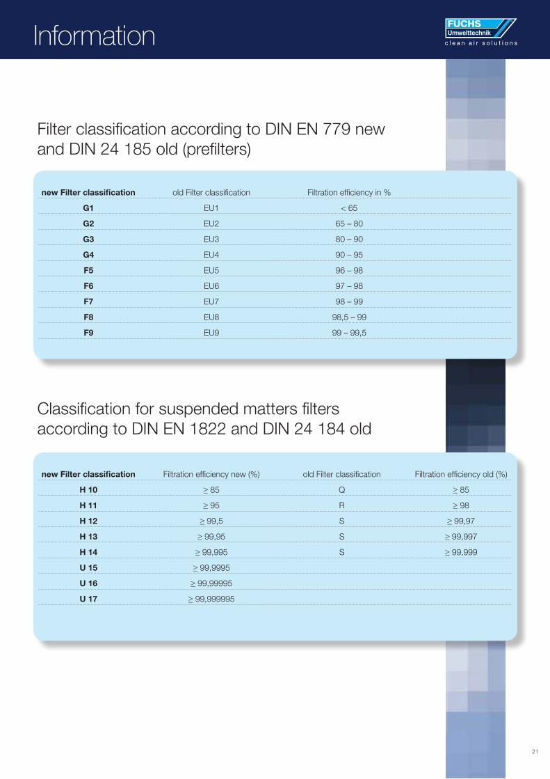
Filter classification according to DIN EN 779 newand DIN 24 185 old (prefilters)
Classification for suspended matters filters according to DIN EN 1822 and DIN 24 184 old
new Filter classification old Filter classification Filtration efficiency in %
G1 EU1 < 65
G2 EU2 65 – 80
G3 EU3 80 – 90
G4 EU4 90 – 95
F5 EU5 96 – 98
F6 EU6 97 – 98
F7 EU7 98 – 99
F8 EU8 98,5 – 99
F9 EU9 99 – 99,5
new Filter classification Filtration efficiency new (%) old Filter classification Filtration efficiency old (%)
H 10 ≥ 85 Q ≥ 85
H 11 ≥ 95 R ≥ 98
H 12 ≥ 99,5 S ≥ 99,97
H 13 ≥ 99,95 S ≥ 99,997
H 14 ≥ 99,995 S ≥ 99,999
U 15 ≥ 99,9995
U 16 ≥ 99,99995
U 17 ≥ 99,999995
Information

22
Information c l e a n a i r s o l u t i o n s

23
c l e a n a i r s o l u t i o n sc l e a n a i r s o l u t i o n sInformation
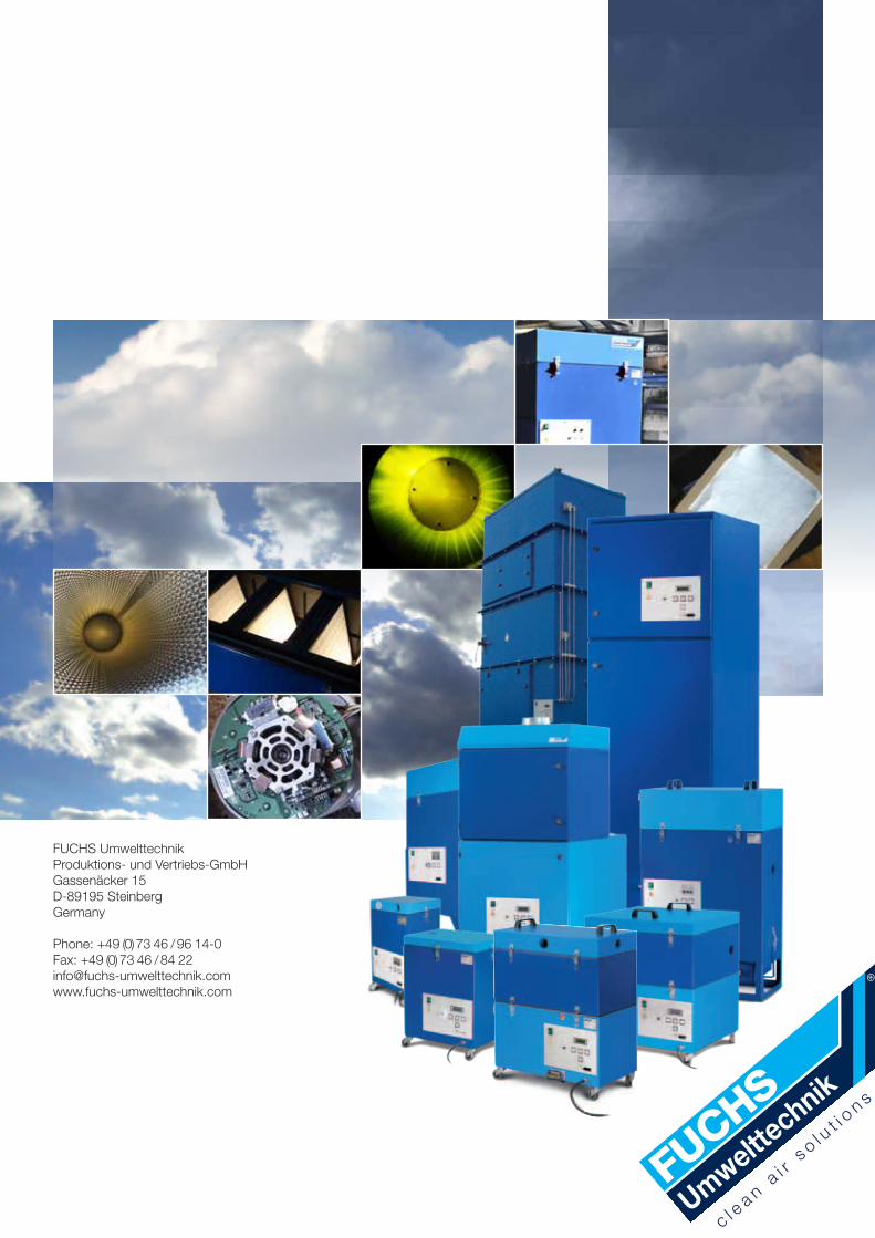
FUCHS Umwelttechnik Produktions- und Vertriebs-GmbH Gassenäcker 15 D-89195 SteinbergGermany
Phone: +49 (0) 73 46 / 96 14-0 Fax: +49 (0) 73 46 / 84 22 [email protected]
c l ea n a
i r s o l u
t i on s