RAIL SURFACE TREATMENT - Chalmers
68
Department of Mechanics and Maritime Sciences CHALMERS UNIVERSITY OF TECHNOLOGY Gothenburg, Sweden 2019 RAIL SURFACE TREATMENT GRINDING AND MILLING – COMPETING OR COMPLEMENTARY TECHNOLOGIES Master’s thesis in Materials Engineering Erika Steyn
Transcript of RAIL SURFACE TREATMENT - Chalmers

Department of Mechanics and Maritime Sciences CHALMERS UNIVERSITY OF TECHNOLOGY Gothenburg, Sweden 2019
RAIL SURFACE TREATMENT GRINDING AND MILLING –
COMPETING OR COMPLEMENTARY TECHNOLOGIES Master’s thesis in Materials Engineering
Erika Steyn


MASTER’S THESIS IN MATERIALS ENGINEERING
RAIL SURFACE TREATMENT
GRINDING AND MILLING –
COMPETING OR COMPLEMENTARY TECHNOLOGIES
Erika Steyn
Department of Mechanics and Maritime Sciences
Division of Dynamics
CHARMEC
CHALMERS UNIVERSITY OF TECHNOLOGY
Göteborg, Sweden 2019

RAIL SURFACE TREATMENT
GRINDING AND MILLING –
COMPETING OR COMPLEMENTARY TECHNOLOGIES
Erika Steyn
© Erika Steyn, 2019-06-05
Master’s Thesis 2019:20
Department of Mechanics and Maritime Sciences
Division of Dynamics
CHARMEC
Chalmers University of Technology
SE-412 96 Göteborg
Sweden
Telephone: + 46 (0)31-772 1000
Cover:
HSG train developed by Vossloh and CRCCE for use on Chinese railways - HSG is
described in Section 4.2 [1]
Department of Mechanics and Maritime Sciences
Göteborg, Sweden 2019-06-05

CHALMERS, Mechanics and Maritime Sciences, Master’s Thesis 2019:20 I
RAIL SURFACE TREATMENT
GRINDING AND MILLING –
COMPETING OR COMPLEMENTARY TECHNOLOGIES
Master’s thesis in Materials Engineering
Erika Steyn
Department of Mechanics and Maritime Sciences
Division of Dynamics
CHARMEC
Chalmers University of Technology
Abstract
Railway maintenance programs worldwide use rail grinding to combat surface defects
such as corrugations and rolling contact fatigue. However, emerging technologies
including variations on rail grinding and rail milling are gaining interest in the railway
maintenance industry. Limited academic literature is available on these alternative
surface treatment methods. This thesis work investigates supporting literature on rail
grinding and milling technologies, and provides insight into the working principles,
impact on the rail surface and the application possibilities for each technology.
Recommendations are made on the most suitable technology for various maintenance
activities and current best practices are discussed. It has been found that conventional
rail grinding dominates current practices, but technologies such as rail milling and high
speed grinding are becoming increasingly popular on high density networks as in China
and Germany. These methods are shown to have unique characteristics that can be used
to improve railway maintenance strategies by complementing current practices.
Key words:
Rail grinding, rail milling, railway maintenance, surface treatment, surface defects,
rail maintenance strategies, thermomechanical effects
II CHALMERS, Mechanics and Maritime Sciences, Master’s Thesis 2019:20
YTBEHANDLING AV RÄLER
SLIPNING OCH FRÄSNING –
KONKURRERANDE ELLER KOMPLETTERANDE METODER
Examensarbete inom Materialteknik
Erika Steyn
Institutionen för Mekanik och maritima vetenskaper
Avdelningen för Dynamik
CHARMEC
Chalmers tekniska högskola
Sammanfattning
Över hela världen tillämpas slipning för att åtgärda ytdefekter på räler. Typiska
ytdefekter är korrugering och rullkontakutmattning. Det finns dock intresse för ett flerta
nya ytbehandlingstekniker. Dessa inkluderar såväl utveckling av slipmetoder som
fräsning. Det finns dock få vetenskapliga utvärderingar av dessa alternativa
ytbehandlingsmetoder. Detta examensarbete undersöker den litteratur som finns om
slipning och fräsning. Det ger även en översikt över principerna för de olika metoderna,
beskriver hur de påverkar rälsytan och anger vilka möjliga tillämpningar som finns för
metoderna. Rapporten ger rekommendationer om mest lämplig teknik för olika typer
av underhållsarbeten och diskuterar nuvarande användning av de olika metoderna. Det
visar sig att konventionell rälslipning idag är den dominerande tekniken, men att
intresset för tekniker såsom fräsning och höghastighetsslipning ökar. Detta gäller
speciellt starkt trafikerade linjer i Kina och Tyskland. Dessa nya metoder har visat sig
ha unika egenskaper som kan användas för att förbättra järnvägsunderhållet genom att
komplettera nuvarande metoder.
Nyckelord:
Rälsslipning, fräsning av räl, järnvägsunderhåll, ytbehandling, ytdefekter, strategier
för järnvägsunderhåll, termomekaniska effekter

CHALMERS, Mechanics and Maritime Sciences, Master’s Thesis 2019:20 III
Contents
Abstract ............................................................................................................................................ I
Sammanfattning........................................................................................................................... II
Contents ........................................................................................................................................ III
Preface ............................................................................................................................................. V
Acronyms ..................................................................................................................................... VI
1 Introduction.............................................................................................................................. 1
2 Background ............................................................................................................................... 2
2.1 Rolling stock ..................................................................................................................... 2
2.2 Railway track design ..................................................................................................... 2
2.3 Rail profile ......................................................................................................................... 3
2.4 Rail material ..................................................................................................................... 4
2.5 Rail inspection and testing .......................................................................................... 6
2.6 Rail surface defects ........................................................................................................ 7
3 Maintenance strategies ......................................................................................................11
3.1 Preparative maintenance ..........................................................................................11
3.2 Corrective maintenance .............................................................................................11
3.3 Transitional maintenance .........................................................................................11
3.4 Preventive (cyclic) maintenance ............................................................................12
3.5 Special maintenance ....................................................................................................13
4 Grinding as surface treatment method ........................................................................15
4.1 Conventional grinding ................................................................................................15
4.2 High speed grinding ....................................................................................................18
4.3 High efficiency deep grinding ..................................................................................19
4.4 Abrasive belt grinding ................................................................................................19
5 Milling as surface treatment method ............................................................................21
6 Key phenomena.....................................................................................................................24
6.1 Material removal ..........................................................................................................24
6.2 Surface quality ...............................................................................................................26
6.3 Metallurgical effects ....................................................................................................26
7 Maintenance by grinding and/or milling ....................................................................29
7.1 Criteria for optimised selection ..............................................................................30
7.2 Preparative machining ...............................................................................................31
7.3 Preventive cycle (no visible surface damage) ...................................................31
7.4 Remedial action for corrugations ...........................................................................31

IV CHALMERS, Mechanics and Maritime Sciences, Master’s Thesis 2019:20
7.5 Remedial action for head checks ............................................................................32
7.6 Rail reprofiling ...............................................................................................................33
8 Global strategies ...................................................................................................................35
8.1 Sweden .............................................................................................................................36
8.2 North America ...............................................................................................................38
8.3 Australia ...........................................................................................................................41
9 Conclusions .............................................................................................................................44
10 Future work ............................................................................................................................45
Appendix A: Sweden .....................................................................................................................46
Appendix B: North America .......................................................................................................47
Appendix C: Australia ...................................................................................................................49
Appendix D: Rail transport goals .............................................................................................52
References ........................................................................................................................................53

CHALMERS, Mechanics and Maritime Sciences, Master’s Thesis 2019:20 V
Preface
This Master’s thesis was carried out between January and June 2019 at the Dynamics Division of the Department of Mechanics and Maritime Sciences, Chalmers University of Technology, Sweden. The work is part of the activities within the National Centre of Excellence in railway mechanics, CHARMEC. It focusses on the feasibility and application of rail grinding and rail milling as surface treatment technologies for railways. I was fortunate to work in a department with a wealth of knowledge, but I want to thank particularly my supervisors, Professor Anders Ekberg and Doctor Björn Paulsson, whose insight, guidance and patience have been invaluable to me. Also, Professor Elena Kabo, who acted as examiner, and was always willing to give some clarity or insight to motivate me to do my best. I have learnt so much from this team, and I hope to be fortunate enough to work with them again in future. Further, I want to thank everyone that provided invaluable information into industry and research practices, with a special thanks to Matthias Asplund (Trafikverket) and Doctor Hengyu Wang and his team at Southwest Jiaotong University. This thesis has been produced during my scholarship period at Chalmers University of Technology, which was made possible through my Swedish Institute scholarship. Finally, a special thanks to my family – altyd my hart se punt. Göteborg June 2019 Erika Steyn

VI CHALMERS, Mechanics and Maritime Sciences, Master’s Thesis 2019:20
Acronyms
AAC Association of American Railroads AREMA American Railway Engineering and Maintenance-of-Way Association ARTC Australian Rail Track Corporation BNSF Burlington Northern Santa Fe Railroad CEN European Committee for Standardization CER Community of European Railway and Infrastructure Companies CN Canadian National Railway CPR Canadian Pacific Railway CRCCE China Railway Construction Corporation subsidiary DIN Deutsches Institut für Normung (German national organization for
standardization) EN European Norm (European standard) FRA Federal Railroad Association FTA Federal Transit Administration HEDG High efficiency deep grinding HSG High speed grinding IM Infrastructure manager JIS Japanese Industrial Standard JSA Japanese Standards Association MFL Magnetic flux leakage mgt Million gross tons (imperial; 1 US ton = 0,907 tonne) MGT Million gross tonnes (metric ton) mph Miles per hour NDT Non-destructive testing NRC National Research Council of Canada RAC Railway Association of Canada RCF Rolling Contact Fatigue RMS Root mean square (also rms) TAL Tonne axle load (Australian terminology) TEN-T Trans-European Transport Network UIC IRS Union Internationale des Chemins de fer (UIC) International Railway
Solution (IRS)

CHALMERS, Mechanics and Maritime Sciences, Master’s Thesis 2019:20 1
1 Introduction
Rail surface treatment with grinding and/or milling significantly improves rail surface quality. Combined with proper lubrication practices, inspection and maintenance, it can extend rail life by more than 100 % [2, 3]. This is particularly beneficial from an economic point of view, since track related costs represent 50–60 % of a typical railway’s maintenance and renewal expenditure [4]. In 2016 the average annual maintenance and renewal cost in Western Europe was estimated to be about €50 000 per kilometre of conventional track [5]. Figure 1 shows how planning, design and construction are the predominant influences on the total cost of a railway for the first few years. Maintenance will determine the total cost over the remainder of the railway life up until rail replacement. This also demonstrates how more efficient maintenance practices could increase the economic rail life.
Figure 1: Influence of maintenance on cumulative total costs (adapted from [5])
Rail surface treatment is typically used to improve the surface quality by removing surface defects and to optimise the wheel—rail contact conditions through rail head reprofiling. Grinding and milling are the surface treatment methods currently preferred in practice; however, rail grinding dominates both in operational use and in supporting research. The focus of this thesis is to establish the capabilities and limitations of these surface treatment methods, and variations thereof, in order to better support the choice of method used. The current global best practices are also evaluated to determine possible areas of improvement. For the purpose of this project, the standard case will be considered as 1435 mm gauge continuous welded Vignole rail with a 60E1 profile and made from standard R260 and R260Mn rail grades. Wherever differentiation is required, conventional mixed traffic will be taken as the baseline for this research. The influence on special rail components, such as switches and crossings, is only briefly considered.

2 CHALMERS, Mechanics and Maritime Sciences, Master’s Thesis 2019:20
2 Background
2.1 Rolling stock
Rolling stock is typically divided into passenger or freight stock, and railways can be distinguished according to the traffic type(s) carried – either as dedicated lines, or mixed traffic. Deterioration of a track is largely dependent on the type of traffic and the extent of track usage. The accumulated tonnage, or the total tonnage borne by the track in a specific timeframe, is therefore an important factor when planning track maintenance. Additionally, dynamic loads as influenced by travel speed, train load and track geometry should also be considered [6]. The load limit for each line is defined according to the UIC line classification in UIC Leaflet 700 [7], although allowed train lengths and load limitations on specific lines are largely regulated by country specific standards. For instance, in Sweden the standard train length limit is currently 630 m; however, the aim is to increase this to at least 750 m in order to meet the TEN-T guidelines [8]. The minimum requirements for freight lines on the core European network, according to the TEN-T guidelines, are that it can handle rolling stock with a minimum length of 740 m and in excess of 22,5 ton axle load, whilst allowing for a line speed of 100 km/h [9].
2.2 Railway track design
The railway track could be divided into the superstructure, consisting of rails, fasteners, sleepers and ballast, and the sub-ballast layer(s) as shown in Figure 2 [6]. Special track components, such as switches and crossings, are included in the railway to lend a specific functionality. Railway track design is based on the operational requirements, such as the intended loading and the operational environment, which includes the foundation conditions and weather conditions. However, track design should also take rail maintenance into consideration [10].
Figure 2: Railway track components (from [6])
Rail is arguably the single most important track component. The main purposes of the rail are to support and guide rolling stock wheels whilst resisting the various

CHALMERS, Mechanics and Maritime Sciences, Master’s Thesis 2019:20 3
loads imposed on it and providing a smooth running surface. The wheel—rail interface and the contact forces are well defined in literature [10–12].
2.3 Rail profile
To ensure optimal wheel—rail contact conditions and to minimise rail wear, a target profile optimised for the specific track and the dominating traffic should be introduced as soon as possible after rail installation. It should also be maintained during the life of the rail; however, the target profile could change over the life of the rail. Optimising the rail profile extends the rail life by reducing contact stresses, which results in the reduction of wear and surface defect formation [13]. Different profiles can be employed on the same track, depending on the geometry; the optimal profile for a tangent track could differ significantly from a high rail in a curve. Therefore, rail profiles need to be evaluated and adapted for the track geometry and applied loads, whilst considering the track maintenance strategies used [12–14].
Figure 3: Rail profile 60E1 (From [15])
In Europe, as-rolled profiles for new rails are standardised according to EN13674. Swedish railways typically use the 50E3 profile (previously BV50) and the 60E1 profile (previously UIC 60), which is shown in Figure 3. These as-rolled profiles are generally also used as target profiles for track reprofiling; however,

4 CHALMERS, Mechanics and Maritime Sciences, Master’s Thesis 2019:20
specialised profiles can be used to minimise fatigue damage such as excessive wear or head checking. These specialised profiles differ between countries, but there are drives to standardise them across Europe [13, 15, 16]. Some research suggests that target profiles should be adapted during the lifetime of the rail to optimise rail life [17]. This strategy is preferred on lines with uniform traffic; therefore, on heavy haul lines it is often beneficial to allow the rail profile to develop according to the traffic it carries [16]. As rails and wheels wear, the contact area changes and high stress conditions may develop, which could decrease wheel life by up to 50 % [18,19]. It is argued that wear and the resultant rail surface damage, can be managed by shifting the contact band. One approach to this is referred to as pummelling [19]. On the other hand, mixed (and passenger) traffic tracks have much higher demands on safety and the wheel–rail contact forces differ significantly to that on heavy haul tracks. The different vehicles under mixed traffic conditions typically do not relate to the same profile. Therefore, mixed traffic tracks are commonly maintained to a standard profile [13]. Rail profiling can be performed with surface treatment methods such as grinding and milling (an example is shown in Section 5), depending on the maintenance strategy and the amount of material removal called for [14]. Heavier rails should have a longer lifetime, as there is more material that can be removed before replacement is required [10].
2.4 Rail material
Table 1: Chemical composition and mechanical properties of standard rail grades (R260 and R260Mn) (based on data in [15])
R260 R260Mn Chemical composition [% by mass] Carbon (C) 0,60/0,82 0,53/0,77 Silicon (Si) 0,13/0,60 0,13/0,62 Manganese (Mn) 0,65/1,25 1,25/1,75 Phosphor (P) max. 0,030 0,030 Sulphur (S) 0,008/0,030 0,008/0,030 Chromium (Cr) max. 0,15 0,15 Aluminium (Al) max. 0,004 0,004 Vanadium (V) max. 0,030 0,030 Nitrogen (N) max. 0,010 0,010 Oxygen (O) max.(a) 20 20 Hydrogen (H) max. (a) 2,5 2,5 Mechanical properties Tensile strength (Rm) min. [MPa] 880 880 Min. elongation [%] 10 10 Centre line running surface hardness [HBW] 260/300 260/300 (a) Unit: 10-4 % (ppm)

CHALMERS, Mechanics and Maritime Sciences, Master’s Thesis 2019:20 5
Rail grades are standardised globally, although different designations are used in different regions [20]. In Europe, EN 13674 specifies seven standard grades of pearlitic steel with a variety of characteristics. The different grades are distinguished based on hardness, composition and whether they are heat treated. R260/R260Mn are both pearlitic steels; however, the EN 13674 standard allows for some ferrite to be present at grain boundaries – no increased hardness constituents, such as martensite, are allowed. The chemical composition and mechanical properties as specified for these two grades are given in Table 1 [15].
When evaluating rail grades, it is important to consider the material in terms of hardness and ductility, but also from a maintenance point of view – looking at properties such as wear resistance, weldability and the probability of manufacturing defects to be present [10]. Rail grades R260 and R260Mn are almost identical, with the main difference being the manganese content. Manganese, along with silicon, is considered a good solid solution strengthener for ferrite – in pearlite, it reduces the interlamellar spacing, which alone will result in significant increases in yield strength. Consequently, R260Mn can have a lower carbon content, whilst maintaining the same strength values as R260 [21]. Carbon content should be optimised to ensure sufficient strength for the duration of the rail life. Both too little or too much carbon can result in increased rolling contact fatigue (RCF) [22]. Higher carbon content provides a harder rail surface which is more wear resistant; however, this increases the risk of martensite forming during rail surface treatment, such as grinding or milling. Martensite formation results in a more brittle surface and a decrease in ductility of the rail material. Harder rails also require better profile precision (see Section 6.3) and increased grinding power. Generally, rail life can be extended by using premium (harder) rails [4, 23, 24]. To avoid having a too high carbon content, alloying elements are added to increase rail strength and to obtain a desired microstructure. Limited amounts of silicon and vanadium can be added – both are grain refiners and solid solution strengtheners which increases the toughness, ductility and yield limit of the steel [25]. Vanadium is limited as it increases the ductile-brittle-transition-temperature of the material. Chromium is added to achieve a fully pearlitic structure and increases the hardening capacity of the steel; however, it can limit rail weldability [21, 25, 26]. EN 13674 has explicit requirements with regards to the hydrogen and oxygen content of a new material. Both these elements increase the risk of (subsurface initiated) rolling contact fatigue. Oxygen is removed to limit the amount of non-metallic inclusions (oxides), which can cause subsurface rolling contact fatigue. Excessive hydrogen in turn can cause hydrogen embrittlement that can result in subsurface cracks. The alloy composition will however determine the extent to which hydrogen and oxygen may negatively influence the material properties [15].

6 CHALMERS, Mechanics and Maritime Sciences, Master’s Thesis 2019:20
2.5 Rail inspection and testing
Rail maintenance programs aim at minimising traffic disturbances whilst keeping maintenance costs to a minimum and maintaining track safety. Non-destructive testing (NDT) can be used to detect defects at an early stage and to understand the deterioration of the rail. This enables railways to efficiently schedule future maintenance activities and to gather data to optimise predictive maintenance strategies [12].
The choice of detection method and testing technology used often depends on the available maintenance windows. This will determine the speed of detection and accessibility required, as well as the extent of damage allowed before maintenance needs to be performed. Several detection methods are used in practice with varying levels of operator involvement; however, in all cases the detected defect data needs to be verified and interpreted by a qualified operator. In most instances, visual inspection is used in conjunction with technologies such as ultrasonic, induction and eddy current testing [12, 27]. In practice, inspection of shallow cracks (using technologies such as eddy current) are primarily executed for economic benefits, as it can be used to specify maintenance which subsequently improves rail life. Inspections for long cracks (using technologies such as ultrasonic testing) on the other hand is performed primarily for safety reasons. In the following sections, common inspection methods used to detect surface and subsurface cracks are described.
Visual and manual inspection
Visual inspection can be used to detect, characterise and monitor surface defects. Manual inspection methods such as dye penetrant testing and magnetic particle testing [28], as well as automated camera systems can be used to supplement visual inspection results [27, 29]. For rails, this is generally a time consuming method with low accuracy, as many defects are overlooked [30].
Ultrasonic testing
Ultrasonic testing is arguably the most widely used method for detecting and characterising both internal and external rail defects; however, accuracy for detecting surface-breaking defects are lower. Early stage defects at various angles throughout the rail head can be detected [12]. However, it is typically more applicable for deeper defects, as a minimum detection depth of at least 2 mm applies (depending on the specific method use). Specialised handheld equipment is used for special track components such as switches and to verify defects identified by inspection trains before deciding on maintenance actions. Ultrasonic trains have been used since the 1960’s and are used to efficiently inspect entire rail networks at a high measuring speed. Currently, possible inspection speeds are reported up to 100 km/h [11, 27, 30].

CHALMERS, Mechanics and Maritime Sciences, Master’s Thesis 2019:20 7
Induction
Also called magnetic flux leakage (MFL) testing. Induction is often used as a supplement to technologies such as ultrasonic testing. An induced magnetic field is passed through the rail head – when a surface anomaly is present, it will cause a distortion in the current flow. Evaluation of the test results requires a high level of operator involvement [12, 27]. Eddy current
Pulsed eddy currents can detect most shallow RCF defects with high accuracy. Typical feedback includes the defect location and some defect characteristics, such as the extent or quantity. Various types of sensors on both handheld and train mounted equipment are being used in industry [27]. It is also being introduced on maintenance machines as a quality control tool. Defect detection limitations
The condition of the scanned rail surface can significantly influence the NDT results. A poor surface quality can result in false or inaccurate scanning data, and consequently underlying defects can be missed. The surface quality can be influenced by external factors such as excessive lubrication or debris on the rail; however, faulty measurements are more likely due to surface defects such as corrugation or a network of shallow head checks [12].
2.6 Rail surface defects
The wheel—rail interface is susceptible to develop surface defects that can be detrimental to rail safety and rail life, and it is often a major cause for rail maintenance and replacement. The identification and classification of rail surface defects are well understood [12, 29–31], and various organisations globally are responsible to ensure industry wide consensus on the causes and handling of these defects. For the purpose of this project, the classification according to UIC IRS 70712 will take precedence. In this section, some defects are described to highlight the classification, causes and the management thereof, as applicable to this project. The specific defects discussed are those that can typically be managed with rail surface treatment such as rail grinding or rail milling. In some instances, defects can only be corrected through reprofiling or corrective surface treatment if detected early enough. If the defect is too deep or too severe, the only possible remedial action is rail replacement. Some examples of where UIC IRS 70712 suggests surface treatment as remedial action for early stage defects are:
- Squats – UIC IRS Code 127 or 227 (depending on location); see Figure 4. Preventive maintenance can reduce the occurrence of these defects.

8 CHALMERS, Mechanics and Maritime Sciences, Master’s Thesis 2019:20
Corrective action can be taken if detected early enough – in these cases, milling or deep grinding are recommended as potential actions [29].
- Wheel burns – UIC IRS Code 2252; see Figure 5. Wheel burns can be removed by grinding if the damage is slight [29].
- Long grooves, UIC IRS Code 2212 (Figure 6), and lines, UIC IRS Code 2213 (Figure 7) can be remedied through reprofiling, if not too deep [29].
- Flaking – see Figure 8. UIC IRS Code 2221. Flaking is very similar to spalling but is typically found near the gauge corner. It is shallow and can be removed by reprofiling [29].
Figure 4: Squats (code 227) (from [29])
Figure 5: Wheel burns (code 2252) (from [29])
Figure 6: Long grooves (code 2212) (from [29])
Figure 7: Lines (code 2213) (from [29])
Figure 8: Flaking (code 2221) (from [29])
Other surface defects can be managed as part of a railway’s management plan. The following subsections describe the defects that can be successfully removed with surface treatment, such as grinding or milling. Rail corrugation
UIC IRS Code 2201: Short-pitch corrugation UIC IRS Code 2202: Long-pitch corrugation

CHALMERS, Mechanics and Maritime Sciences, Master’s Thesis 2019:20 9
Rail corrugation is a form of rail wear, where the running surface is worn in an irregular wave-like pattern much like corrugated plate. The depressions could be more or less pronounced with varying wavelengths. Short-pitch corrugations, as shown in Figure 9, can be distinguished through the bright ridges and dark hollows and can be found on any system. On the other hand, long-pitch corrugations as seen in Figure 10, are more prevalent on the inside stretch of curves and on heavy haul lines [12, 29].
Figure 9: Short-pitch corrugation (from [29])
Figure 10: Long-pitch corrugation (from [29])
Corrugation can be detected through visual inspection, as well as acoustic testing, acceleration and profile measurements. The UIC IRS 70712 recommendation is to grind or mill (for long-pitch corrugation) the rail surface, if it is called for as part of the rail maintenance program. Machining is also recommended when corrugation could damage the rolling stock running gear, reduce passenger comfort or if it is detrimental to the environment (due to high noise levels) [29]. Head checks
UIC IRS Code 2223
Figure 11: Gauge side head checking and flaking (from [12])
Head checks are small, transverse surface cracks more commonly found on the gauge corner of high rails in curves; however, it is also found on straight lines and switches. Several cracks develop in parallel and in close proximity. Figure 11 shows an example of gauge side head checking and flaking. Detection can be through visual inspection, ultrasound and eddy current testing. Head checks should be removed before they propagate downwards into the rail,

10 CHALMERS, Mechanics and Maritime Sciences, Master’s Thesis 2019:20
as this could result in a rail break. The recommended remedial actions are reprofiling as prevention and rail grinding to remove cracks. Rail milling is suggested as an alternative for deeper cracks; however, this is dependent on the railway’s maintenance strategy [12, 29]. Spalling
UIC IRS Code 2211
Spalling is a form of surface initiated rolling contact fatigue similar to head checks. Less severe cases are often rather considered as a light case of flaking. A network of shallow cracks form on the top of the rail surface due to high contact stresses and parent metal is displaced from the running surface, as shown in Figure 12. Therefore, it is most commonly found in areas of high contact stress, such as low rails in sharp curves.
Figure 12: Spalling on the rail head surface (from [29])
Spalling cracks results in metal loss or delamination and do not propagate deeper into the rail head. Typically it can be identified by visual inspection and, if detected early enough, remedied using surface treatment methods such as grinding or milling [12, 29].

CHALMERS, Mechanics and Maritime Sciences, Master’s Thesis 2019:20 11
3 Maintenance strategies
Rail maintenance strategies aim to optimise the economic rail life within the limitations of available track maintenance time, while ensuring safe operations. Surface treatment methods that remove running surface material, such as grinding and/or milling (so-called artificial wear treatment), are here employed to remove surface defects and maintain rail profiles [12]. In principle, the intent is to replace a rail only once metal removal is no longer a possible option.
3.1 Preparative maintenance
Preparative maintenance is performed as soon as a new rail is integrated into the existing infrastructure. The aim is to provide a smooth running surface free from mill scale. Optimal initial conditions are further ensured by removing any rust or surface damage caused during the construction process and by introducing a target profile as described in Section 2.3 [13, 24]. On the Swedish network, material removal with this strategy is between 0,2 mm and 0,3 mm [32].
3.2 Corrective maintenance
Corrective (or reactive) maintenance is a remedial activity to address critical rail surface defects detected during rail inspections. This type of maintenance typically results in a considerable amount of metal removal (between 0,5 mm and 6 mm). Simultaneously, the work hardened surface of the rail head is removed, which means a new work hardened surface will need to be built up by the operational traffic after artificial wear treatment. The intent with corrective maintenance is to remove all or as much of the surface defects as possible; however, this process can take a lot of time which is not always feasible on an operational track. In these instances the aim is to reduce the size of the defects as much as possible – maintenance activities can then be planned to remove the remaining damage [12, 24].
3.3 Transitional maintenance
Transitional maintenance here refers to the interim strategy used to change from a corrective to a preventive maintenance strategy. The rail surface is machined during transitional maintenance in order to remove all surface damage [24]. This can be done either in a major campaign or more gradually (preventive–gradual maintenance).

12 CHALMERS, Mechanics and Maritime Sciences, Master’s Thesis 2019:20
In preventive-gradual maintenance, all surface damage is not removed at once. This maintenance process is a performed at slower rates than preventive maintenance cycles. In order to start the gradual transition, frequent shallow machining passes is used. This is gradually changed to less frequent passes with higher cut depths. As the metal removal is increased, the artificial wear pattern is optimised until all surface defects are removed and a desired profile is machined. After this the preventive maintenance strategy can be implemented [12, 24].
3.4 Preventive (cyclic) maintenance
Preventive rail grinding was introduced in Canada by the National Research Council (NRC) in the 1980’s as a rail maintenance strategy to maximise rail life by managing RCF [33]. Today, the preventive maintenance strategy (as illustrated in Figure 13) is generally considered to be the most beneficial strategy for RCF management [34].
Figure 13: An ideal maintenance program as proposed by ProRail (The Netherlands) (from [34])
The strategy aims at removing material at more frequent intervals. This allows for the management of rail surface defects while maintaining the surface quality and rail profile. Defects are removed early on, therefore, the defect size and rate of propagation is reduced, which prevents defects from becoming a risk to rail safety. Longitudinal irregularities such as corrugation are also mitigated through artificial wear treatment such as rail grinding and/or milling. This is beneficial both to ride comfort and controlling noise levels [12, 24]. Machining according to a preventive strategy is tailored for different rail sections. Sections more prone to develop RCF, such as sharp curves, are scheduled more frequently than tangent track [12]. By removing less material at a regular frequency, the rail life is significantly increased on standard rail grades. In theory, premium heat treated rails need surface treatment less frequently; however, a higher profile precision is required due to the lower amount of wear [35]. As less material is removed, machining can be performed at higher speeds, which is crucial for high density rail networks.

CHALMERS, Mechanics and Maritime Sciences, Master’s Thesis 2019:20 13
On the BNSF railway in North America, a comparison between corrective and preventive grinding on a heavily curved track section showed that the corrective grinding strategy required 59 % more time than needed for the preventive strategy (see Table 2) [36]. In addition, applying a preventive strategy allows for detailed scheduling of maintenance and ultimate replacement of the track. Finally, performing preventive maintenance reduces the occurrence of critical defects that may create risk for rail breaks [12, 24, 31]. Table 2: Comparison of track posession time for preventive and corrective grinding maintenance on the BNSF railroad, USA (adapted from [36])
Preventive Corrective
Curve passes per cycle 1 4
Cycles per year 4 1
Grinding speed 9,6 km/h 9,6 km/h
Travel speed 16 km/h 16 km/h
Time to reverse direction n/a 0,75 min per pass
Grinding time per cycle 70 min 362 min
Travel time per cycle 34 min 300 min
Total track time per cycle 104 min 662 min
Number of 2 hr windows per cycle 1 6
Number of 2 hr windows per year 4 6
Total track time per year 416 min 662 min (+ 59 %)
Contrary to corrective maintenance (grinding and/or milling), the work hardened surface layer is usually not removed during preventive maintenance. Therefore, the rail surface is generally more resistant against plastic deformation and subsequent development of RCF defects. A preventive maintenance strategy can be optimised to maximise rail life, improve rail surface quality and to decrease wear rate (of both operation and maintenance activities) and maintenance cost [24, 31].
3.5 Special maintenance
In some special cases the required grinding does not fall strictly within the scope of the above strategies. For instance, rail reprofiling as described in Section 2.3 can be done as part of a preventive strategy; however, for some rails it could be required less frequently, therefore it is not necessarily made part of the regular track maintenance strategy.

14 CHALMERS, Mechanics and Maritime Sciences, Master’s Thesis 2019:20
Surface treatment to reduce noise (acoustic surface treatment) can also be considered as a special category. This is usually done on a need-basis for environmental reasons in order to reduce noise pollution [24]. Switches and crossings
Switches and crossings have complex geometries (see Figure 14 and [6]) and typically higher forces act on these components than on the rest of the rail. Consequently, maintenance of these components is more complex [37]. Large production machines can typically not be used; therefore, special maintenance slots with either smaller or handheld machines need to be incorporated into the railway’s maintenance program [36]. However, currently surface treatment equipment manufacturers are introducing larger production machines capable of performing switch maintenance [38, 39]. There are some considerations that should be kept in mind with regards to switch grinding, such as [38–40]:
• Specialised equipment is required; alternatively, handheld machines should be used.
• Maintenance programs often require only switches on the main line to be ground, unless maintenance is also required on the secondary line.
• Grinding operations on check rails (guard rails) can change the connection between that and the rail – in these cases adjustment of the guard rails after grinding might be required.
• The contact band on high and low rails in switches can be tailored respectively in order to reduce the amount of wear in the switch.
• When grinding switches, a rail length (as determined by the relevant rail maintenance program) before and after the switch must be included to ensure for a smooth transition. This length of rail should be defined in the corresponding maintenance instructions.
Figure 14: Turnout components (from [41])

CHALMERS, Mechanics and Maritime Sciences, Master’s Thesis 2019:20 15
4 Grinding as surface treatment method
Rail grinding has been used as a rail surface treatment method since the early 1900’s to clean the head surface. However, in the 1980’s Australian heavy haul railways started applying it to remedy RCF defects and to maintain rail head profiles. Rail grinding has developed to become an inherent part of preventive rail maintenance programs. With the development of the method, rail grinding equipment have also been improved significantly – today, rail grinding is performed globally with automated grinders that can be programmed with predetermined grinding patterns. It has been proven to be an efficient means of extending rail life by decreasing the rate of defect development. Consequently, the cost of maintenance is also reduced [12, 24, 37]. Rail grinding is a process of artificially induced wear with the intent of removing the surface layer of the rail head in order to achieve the desired profile and remove any surface damage. The amount of metal removal is a much-researched field. A metal removal rate that results in a balance between removed material and crack initiation is often referred to as the magic wear rate [16, 24, 31]. The material removal can however be achieved in several ways.
4.1 Conventional grinding
Conventional rail grinding refers to the process currently most commonly used. In principle the grinding process is based either on rotating or longitudinally oscillating stones [11]. Most rail grinding machines in operation today are equipped with several rotating grinding wheels [12, 17]. The number of wheels significantly influences the capacity of the grinder. Smaller machines using 8 to 24 wheels can be used for specialised or occasional grinding, for instance when grinding new welds. Larger machines, with up to 120 grinding stones, are used for production grinding and are often capable of successfully reprofiling a track with a single pass [12, 37]. The grinding wheel arrangement directly affects the efficiency of the grinding process. Each grinding stone creates a facet on the rail head at a different angle, as shown in Figure 15. The character of the facet depends on the position of the stone and the extent of metal removal. The angle at which a grinding stone is placed in relation to the rail head, determines the position and extent of contact between the grinding wheel and the rail head. Despite the grinding wheels being on the order of 90 mm wide, no single grinding facet is wider than 20 mm [17, 37]. The obtained rail profile and surface finish is dependent on the width of these facets. By increasing the number of facets, the rail profile can be matched more accurately. The amount of grinding facets can be increased either by performing several grinding passes or by increasing the number of grinding stones, which both increase the cost. In order to minimise the required maintenance time, it is

16 CHALMERS, Mechanics and Maritime Sciences, Master’s Thesis 2019:20
more efficient to increase the number of stones as on the larger production-grinders [12, 17, 37].
Figure 15: Grinding motor angle positions on rail head (from [37])
Figure 16: Standard rail grinding pattern distribution achieved by a grinding train (adapted from [37])
Detailed rail grinding patterns are developed as part of the rail maintenance program; however, there are several standard rail grinding patterns, like the one in Figure 16 [12, 17, 37]. In Zarembski’s The Art and Science of Rail Grinding, several specialised patterns are described – for instance patterns tailored for specific rails or to address heavy corrugation [37]. A grinding pattern entails more than just the positioning of the grinding stones. Rather it refers to the distribution of facets, which is influenced by several other factors, including the amount of material removed, the contact area between

CHALMERS, Mechanics and Maritime Sciences, Master’s Thesis 2019:20 17
grinding stone and rail head, the applied pressure and the grinding speed [17]. In practice, conventional grinding trains have grinding wheel surface speeds of up to 50 m/s [24]. Here, train operating speeds are considered typically between 2 km/h and 20 km/h, although some manufacturer data suggests possible speeds of up to 32 km/h [43]. With the development of high speed grinding (HSG, see Section 4.2), conventional grinders are being adapted to grind over a wider speed range, effectively combining the conventional and high speed grinding techniques into the same technology. The speed of the grinding operation is of particular importance, as it does not only affect the parameters of the process, but also the required length of maintenance slots, which in turn affects the economic feasibility of rail grinding as a maintenance technique.
Figure 17: Wheel rail grinding (from [42])
Grinding wheels can have either cylindrical or end face-contact with the rail surface, as shown in Figure 17. The abrasive wear from grinding stones can be characterised and quantified to give an understanding of the contact mechanics involved and to determine the grinding ratio [17]. In essence, the metal removal area and consequently the grinding productivity, is determined by the grinding wheel position, the amount of force applied on the rail head, the motor power and the grinding speed [37]. Increasing grinding speed can result in decreased material removal; however, this can be compensated for by increasing the pressure (force on rail head) and motor power [12, 17, 42]. Grinding at high power and low speed, especially with coarse grinding stone grits, will result in a higher surface roughness of the rail head [12, 44]. This can be controlled by the composition of the grinding stones. The material removal rate is also affected by the grinding stone composition. Grinding stones are generally made of abrasive grit bonded by resin. Both the grit characteristics, such as material, dimensions and number of active grains, and the nature of the bonding will determine the grinding capacity or characteristics, and the life of the stone. Aloxite (Al2O3), or aluminium(III)oxide, is often used in grinding stones, due to its hardness, strength and low cost [23]. The grit characteristics directly impacts the pressure distribution on the rail surface. This ultimately influences the efficiency of the grinding operation. Larger abrasive grains will result in increased material removal and an increase in surface roughness [12, 17].

18 CHALMERS, Mechanics and Maritime Sciences, Master’s Thesis 2019:20
4.2 High speed grinding
High speed grinding (HSG) is a specialised rail grinding method developed in Germany primarily to prevent rolling contact fatigue and corrugation. The grinding wheel surface speed in HSG is classified as anything exceeding 50 m/s (the maximum speed for conventional grinding) – typically somewhere between 60 m/s and 80 m/s [24, 45]. High speed grinding trains are currently capable of reaching operating speeds of 26 km/h and higher [37, 46]. This is especially beneficial on high-density rail networks with high operational speeds or on specific lines with short maintenance windows for preventive maintenance. High speed grinding is a rotational grinding technique as shown in Figure 18. The grinding stones can be set up to form a rigid unit – effectively working as a single file on the rail surface. This results in smaller metal chips being produced during the grinding operation. A metal removal depth of around 0,05 mm (at 26 km/h) to 0,15 mm per pass is currently reported in literature. It should be noted that higher grinding speeds result in lower material removal per pass – at speeds of around 60 km/h, it is estimated that at least three grinding passes are required to remove 0,1 mm material [47]. Grinding facets are minimised or eliminated entirely. Thus, HSG can be considered as a fast, controlled process for light grinding maintenance [24, 47].
Figure 18: High speed grinding method (Vossloh) (from [47])
Current research conducted in China [45] is aimed at further increasing the operational speed for HSG. Figure 19 shows the ground surfaces obtained at different grinding speeds – this test rig is capable of grinding at wheel speeds of up to 120 km/h. The technology is also being tested in HSG trains with successful test runs at speeds up to 60 km/h. This is supported by claims from HSG train manufacturers of possible operating speeds of up to 80 km/h [47, 48]. In these studies it has been found that HSG often results in better surface qualities (but lower removal rates) than conventional grinding, which will result in improved wheel—rail interaction [45].

CHALMERS, Mechanics and Maritime Sciences, Master’s Thesis 2019:20 19
Figure 19: Test rid and surface quality after HSG at different operational speeds (from [45])
HSG is gaining interest in industry – it is widely used in Germany but has been investigated on other networks including Denmark, Switzerland, China and Sweden. The Automain and IN2TRACK projects highlight some advantages of HSG, including a possible reduction of 67 % in track possession time when using HSG and twin HSG instead of conventional grinding [24, 47, 49]. However, scientific evidence, especially on the achievable amount of material removal at higher speeds, is still lacking.
4.3 High efficiency deep grinding
High efficiency deep grinding (HEDG) is claimed to be an improvement on HSG in that it allows for a deeper cut at the same (or higher) working speeds, therefore resulting in improved material removal rates [24]. Theoretically, a drawback of higher grinding speeds is the temperature increase at the rail surface. An increased grinding depth should increase the surface temperature since it relates to a larger metal removal energy. However, the HEDG process is optimised in the sense that it combines high speed and high cutting depth. The working speed (vehicle operational speed) as well as grinding wheel speed of this process is comparable to that of HSG. This changes the thermal behaviour of the working surface: the high wheel speed results in high contact surface temperature, which in turn allows for increased material removal (in essence, due to the softening of the material). Due to the high wheel speed, the grinding chip is removed rapidly. With the fast chip removal and passing of grinding equipment, the heat should be removed before significant heat transfer into the rail occurs [24]. Although HEDG has not yet been field tested, it could be considered as a potential extension of preventive rail reprofiling operations.
4.4 Abrasive belt grinding
Abrasive belt rail grinding is a relatively new technique considered for rail maintenance. It is argued [42] that it can more efficiently remove surface material, whilst grinding temperature and consumable use is decreased. Consequently grinding cost is reduced, and negative thermomechanical effects on the rail head are limited [42].

20 CHALMERS, Mechanics and Maritime Sciences, Master’s Thesis 2019:20
In this process, the contact wheel is covered by an elastic rubber band layer that pushes a removable abrasive belt (the consumable for this process) against the working surface. The properties of the rubber band can cause variations in the contact area, which complicates the contact mechanics – in essence, the contact between the wheel and rail surfaces can be considered as the contact between two cylinders as shown in Figure 20 [42]. This technique has only been tested in experimental setup, but research suggests that it can in future be used as an alternative to conventional rail grinding [42].
Figure 20: Abrasive belt contact state [42]

CHALMERS, Mechanics and Maritime Sciences, Master’s Thesis 2019:20 21
5 Milling as surface treatment method
Rail milling is marketed as a rail surface treatment process that can significantly improve the material removal rate and surface quality of a rail [50]. It has been used for less than a decade and is not yet commonly used in industry. Although rail milling has been gaining interest in the research community, especially within Germany and China, there are still few scientific studies on the performance of rail milling and the effect on the rail steel [51–53].
Figure 21: Working principle of rail milling
(from [50])
Figure 22: Chip formation in rail milling (adapted from
[39])
Rail milling is a form of peripheral milling, where the cutter axis is parallel to the workpiece, as shown in Figure 21 [50]. Material is removed by climb (down) milling as shown in Figure 22 [39], where the cutter rotates with the feed. The chip is of a maximum width at the start of the cut and decreases in width as the cutter rotates. This allows for heat to dissipate within the chip, and minimal heat transfer to the rail. Chips are removed behind the cutter and a clean shear plane once the chip is removed, results in less friction and an extended tool life [54]. In essence, rail milling technology combines the climb milling and planing1 techniques. The resulting technology allows for higher amounts of material removal, whilst adding the capability of accurately machining towards predetermined rail profiles by cutting several facets simultaneously [50]. Milling trains are typically equipped with two or three cutter-heads, installed in units as shown in Figure 23. Metal chips are removed through suction lines into chip containers, leaving little or no debris on the line. This makes the rail milling process very suitable for work in tunnels and on bridges. Apart from the milling units, the trains are usually also equipped with fine grinding units to remove any facets and polish the rail after milling is completed. Rail milling machines typically operate only in one direction [49, 50].
1 Planing is a manufacturing process where the tool moves in a straight line and produces a plane (flat) surface on the workpiece.

22 CHALMERS, Mechanics and Maritime Sciences, Master’s Thesis 2019:20
Figure 23: Milling cutter unit under train [50]
Figure 24: Mobile milling tool [39]
A single cutter head is on the order of 600 mm to 1400 mm and is fitted with cartridges on which tool inserts (blades) of different sizes and orientations are mounted, as shown in Figure 24. The different heads can be adjusted independently during machine operation. When the tool inserts are worn, either a single insert, a cartridge (consisting of about six or seven inserts) or the entire cutter head can be replaced [39, 49–51]. The insert material is typically a hard alloy that has a good wear resistance, high temperature resistance and good corrosion resistance. A surface coating such as Titanium Aluminium Nitride (TiAlN) is typically applied to improve the properties of the cutter. This will also reduce diffusion and chemical reaction between the tool and the rail during high temperature operations. It also provides a low coefficient of friction [51]. The influence of milling speed on the cutting force and cutting temperature has been investigated. Similar as in rail grinding, the cutter power directly impacts tool wear, surface quality and the precision and stability of the cutting assembly on the milling train. An increase in milling velocity up to a saturation level of 1200 rev/min resulted in an increase in cutting force. This is advantageous for high-speed milling operations, as it indicates reduced power consumption at high speeds. Consequently, the productivity and efficiency of the rail milling train is improved. During the milling process, high temperatures are generated in the contact area, which can negatively influence the process efficiency as well as the tool condition. As with rail grinding, higher production speeds allow for faster removal of the cutting chips and consequently reduces the size of the heat affected zone in front of the tool and thermal stresses due to the increased temperature gradient. Although the temperatures are not considered to be detrimental to the rail head, it does impact the tool life – the high temperature reduces the tool hardness and strength, which could negatively impact the tool performance and wear resistance, as well as the resultant surface quality [51]. Rail milling is currently considered as a high material removal, low speed technology. It is used less than rail grinding in industry – in general it is preferred for corrective maintenance and activities that require high material removal. However, the surface quality after rail milling is proven to be higher than current industry standards require, with typical roughness levels between 3 and 5 µm

CHALMERS, Mechanics and Maritime Sciences, Master’s Thesis 2019:20 23
[49, 50]. It has also been shown to be capable of accurately reprofiling a rail with a single pass – Figure 25 shows an example of a milling reprofiled rail [39]. The technology has high potential for improvement. Continuous advances allow rail milling to currently be used for material removal of as little as 0,2 mm. Some manufacturers also claim that successful maintenance of switches and crossings is possible [39, 50].
Figure 25: Plastically deformed rail head (above); Target rail profile obtained through rail milling (below)
(from [39])
24 CHALMERS, Mechanics and Maritime Sciences, Master’s Thesis 2019:20
6 Key phenomena
6.1 Material removal
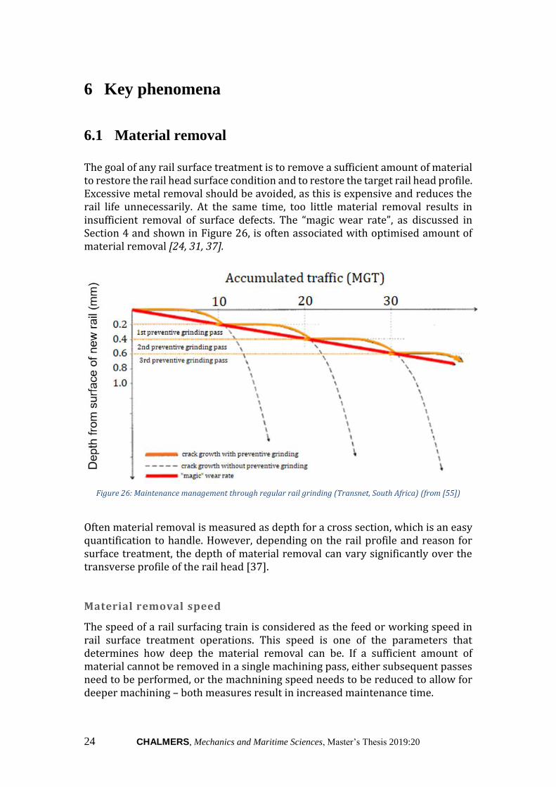
The goal of any rail surface treatment is to remove a sufficient amount of material to restore the rail head surface condition and to restore the target rail head profile. Excessive metal removal should be avoided, as this is expensive and reduces the rail life unnecessarily. At the same time, too little material removal results in insufficient removal of surface defects. The “magic wear rate”, as discussed in Section 4 and shown in Figure 26, is often associated with optimised amount of material removal [24, 31, 37].
Figure 26: Maintenance management through regular rail grinding (Transnet, South Africa) (from [55])
Often material removal is measured as depth for a cross section, which is an easy quantification to handle. However, depending on the rail profile and reason for surface treatment, the depth of material removal can vary significantly over the transverse profile of the rail head [37]. Material removal speed
The speed of a rail surfacing train is considered as the feed or working speed in rail surface treatment operations. This speed is one of the parameters that determines how deep the material removal can be. If a sufficient amount of material cannot be removed in a single machining pass, either subsequent passes need to be performed, or the machnining speed needs to be reduced to allow for deeper machining – both measures result in increased maintenance time.

CHALMERS, Mechanics and Maritime Sciences, Master’s Thesis 2019:20 25
Machining at too high speeds can lead to machining vibration (also called “chatter”) or surface blemishes on the rail surface, leaving an undesirable surface quality. However, too low speeds can result in surface damage due to increased heat input, such as “blueing” or martensite formation (see Section 6.3) [37]. It can also cause gouging of the rail head, which is a form of excessive metal removal resulting in a jagged or rough surface. However, gouging is not common in peripheral grinding operations [56]. The optimal material removal rate will be determined by the specific surfacing technology used. As described in previous sections, most conventional rail grinding trains currently operate at speeds up to about 15 km/h to 20 km/h, whilst high speed grinders can typically reach speeds in excess of 26 km/h [37, 46, 47]. Rail milling machines currently operate at speeds up to 3 km/h [57–59]. Material removal depth
Typically, an increase in speed reduces the depth of material that can be removed by grinding or milling. Therefore, it is often required to do several grinding passes in order to remove a sufficient amount of material. Milling, on the other hand, is slower but can be used to remove more material. A comparison of approximate cutting depths as specified in literature is shown in Table 3. Table 3: Approximate material removal depth at different feed rates (compiled from data in [37, 39, 46, 50, 57, 59])
Speed (km/h) Depth (mm) (a)
Conventional grinding (b)
2,5 0,4 – 0,5 3 0,3 – 0,4 12 0,13 – 0,18
HSG (c) 19 – 26 0,05 to 0,15
Milling (d) 1,2 1,5 2 – 3 0,5 – 1
(a) For a constant speed, the depth depends significantly on the power of the equipment – increased power allows for a deeper cut at a constant speed
(b) For a 1440 horsepower grinding train with 96 grinding stones (c) Based on literature [37, 46]. In industry, HSG trains can operate at speeds up to
80 km/h, with material removal of less than 0,05 mm per pass [47] (d) Taken from equipment data sheets [57–59]
On the other hand, there are also some limitations to the minimum depth of material removal. With high speed grinding it is currently possible to remove as little as 0,05 mm metal in a single pass, whereas milling is typically limited to about 0,2 mm minimum metal removal (depending on the equipment) [24, 59].

26 CHALMERS, Mechanics and Maritime Sciences, Master’s Thesis 2019:20
6.2 Surface quality
Surface roughness due to rail grinding is influenced by several factors, such as the working speed, grinding stone rotational speed, tool characteristics (such as grit size) and motor power and pressure. In addition, the grinding facet size will significantly influence the macrogeometry (macro-roughness) of the resulting rail surface. Table 4 shows an example of acceptable facet widths for a preventive grinding strategy [37]. Table 4: Example of acceptable facet widths for a preventive grinding strategy (from [37])
Facet width Lower gauge corner (+45° to +15°)
[mm]
Mid-gauge corner (+16° to +6°)
[mm]
Contact band (+6° to 0°)
[mm] Heavy Haul 5 8 12 Passenger 4 7 10
Rail micro surface roughness (micro-roughness) is an indication of the condition of the rail head after surface treatment. Surface roughness can be improved (reduced) by reducing the grinding depth or the grinding speed [60]. It is important to obtain an optimised rail surface finish. Too rough surfaces promotes crack initiation and causes increased rail noise and vibration [42]. However, the smoother the required surface, the higher the maintenance costs. The dimensional and shape requirements for rails, including the required surface roughness values, are given in DIN 13231-3. This is similar to the guidelines followed in North America and China [37, 42, 60]. Grinding techniques used in practice typically result in an average surface roughness (Ra) varying from less than 1 μm to over 12 μm [37]. DIN 13231-3 limits the maximum average roughness (Ra) to 10 μm. The ten-point mean roughness (Rz), giving an average of the ten peak values (five highest and five lowest measurements) is limited to 25 µm [60, 61]. It should be noted that some studies suggest that a too fine surface roughness could negatively impact train braking [42].
As described in Section 5, rail milling is typically a climb (down) milling process. Using this technique, the chip thickness is at a maximum at the start of the cut (see Figure 22), resulting in a better surface finish [54]. During the Stage 2 Strabag trials performed by Network Rail (UK) [62], it was concluded that the achieved rail surface finish was superior to that achieved by rail grinding practices. Rail milling equipment manufacturers claim that it is possible to obtain a surface finish of less than 3 µm [50, 57].
6.3 Metallurgical effects
As discussed in previous sections, machining can result in surface damage due to the related heat input. Decreasing the machining speed or increasing the material

CHALMERS, Mechanics and Maritime Sciences, Master’s Thesis 2019:20 27
removal depth can both significantly increase the heat input at a specific cross section on the rail head. Surface treatment techniques should be optimised to limit the thermal effects on the rail suface to maintain the metal properties and limit thermal stresses. High heat input on the rail surface results in microstructural changes in the surface layer material. Due to the nature of the rail grinding process, heat is induced locally and in a thin material layer. When not carefully controlled, this can result in surface damage or microstructural changes, such as “blueing” or martensite formation, due to the high temperature gradients as the material cools down quickly. Figure 27 shows the types of thermal damage that can occur during grinding [23, 37].
Figure 27: Possible thermal damage due to grinding and the relative temperatures at which it occurs (from
[63])
Normally when steel is exposed to oxygen, a very thin oxidation layer forms on the surface. Blueing (or oxidation burn) is the phenomenon where this thin oxide film changes colour as the rail is heated. The colour of the oxide film reflects the temperature to which the rail surface was heated. The characteristic ‘blue’ colour appears around 300 °C. It is mainly observed as a discolaration of the rail. Although not detrimental in itself, the discoloured oxide film indicates that the rail surface has been exposed to elevated temperatures, which could result in other forms of thermal damage. Figure 28 shows how heating steel test pieces to different elevated temperatures affects the colour [63].
Figure 28: Steel tempering colours at different exposure temperatures: (A) normalised; (B) as-quenched; (C)
176 °C; (D) 204 °C; (E) 227 °C; (F) 260 °C; (G) 282 °C; (H) 310 °C; (I) 343 °C; (J) 388 °C (from [63])

28 CHALMERS, Mechanics and Maritime Sciences, Master’s Thesis 2019:20
If the rail is heated to above the martensite transformation temperature (around 700 °C depending on the steel), a martensite layer, or white etching layer, can form on the rail surface [53]. Martensite is a hard and brittle microstructure that is less-densely packed, which results in residual tensile stress below the martensitic layer. Because of the brittleness of martensite, this layer can easily break – it is therefore inclined to defect formation and propagation in the rail surface, and should be limited or avoided [63, 64]. Some studies have indicated the negative effects of grinding at too high power (abusive grinding) in terms of martensite formation and the resulting reduction in rail life [23]. High efficiency deep grinding (HEDG) shows promise in removing sufficient material whilst not allow heat transfer into the rail head – effectively the heat is removed with the grinding chip [24]. Similarly, the down-milling process is designed to reduce friction involved and thus have lower heat transfer at the contact surface [54]. Harder rail grades
Although harder rail grades are not the main focus of this study, it should be noted that the dominating metallurgical effects on these grades differ significantly from that of R260/R260Mn. Harder rail grades are typically heat treated to provide a surface that is more wear resistant. Rails made from these grades often require less frequent grinding during the rail life; however, a better profile match must be ensured, as the increased wear resistance of high-hardness rails does not allow for wear-in of the rail. Grinding operations on hardened rail grades require more diligent control in order to avoid martensite formation and pertinent introduction of residual stresses that may in turn result in an increase in rail surface defects [23].

CHALMERS, Mechanics and Maritime Sciences, Master’s Thesis 2019:20 29
7 Maintenance by grinding and/or milling
Table 5 gives a comparison of the basic operating parameters for the rail grinding and milling processes. Table 5: Overview of characteristics of rail grinding and rail milling (compiled from data in [37, 39, 46, 57–59])
Rail grinding Rail milling
Maximum working speed 15 km/h for conventional
grinding
26 km/h for HSG (a)(b)
3 km/h
Material removal (depth) at
a single pass at low speed
Up to 0,5 mm with conventional
grinding at 2,5 km/h (a)
Up to 1,5 mm at
1,2 km/h
Material removal (depth) at
a single pass at higher speed
Can be less than 0,05 mm with
HSG at 26 km/h (a)
0,5 mm at 3km/h
Minimum possible material
removal
0,05 mm or less (c) 0,2 mm (d)
Surface roughness Varying from less than 1 μm to
over 12 μm (a)
Less than 3 µm is
possible
(a) Grinding stone configuration significantly influences surface roughness,
achievable working speed and material removal depth.
(b) See Section 4.2. HSG has been field tested up to speeds of 80 km/h, with some
studies currently investigating speeds up to 120 km/h. However, current
scientific research only supports metal removal depth data for grinding speeds
up to about 26 km/h. Higher speeds will result in less material removal per pass.
(c) It is difficult to control depth per pass at shallower cut depths.
(d) Minimum cutting depth is limited by the cutter capabilities. In practice it is noted
that cutting depths lower than 0,6 mm could result in lower surface quality [32].
Figure 13 (Section 3.4) shows an optimal maintenance program as proposed by ProRail in the Netherlands [34]. From theory it is possible to provide guidelines for the best choice of technology to achieve such a program. Here, the choice of surface treatment technology depends on several aspects, including:
- The available track access slots will affect the choice of technology. In addition, available resources, such as available equipment, should also be considered. It is important to note that rail surface treatment equipment currently available on the market, can make use of more than one rail treatment technique. For instance, rail grinders can now grind at speeds both from the conventional and high-speed ranges (combining conventional grinding and HSG) [48, 65]. Rail milling machines also typically have some grinding units to smooth out facets left by the milling unit;
- Purpose of surface treatment. A preventive maintenance cycle requires less material removal, whereas corrective maintenance will typically require a higher amount of material removal. Further, acoustic surface treatment has significantly different objectives;

30 CHALMERS, Mechanics and Maritime Sciences, Master’s Thesis 2019:20
- Amount of material removal required. Depending on the extent and nature of surface defects, different amounts of material needs to be removed. This is also dependant on the purpose of the suface treatment – rail reprofiling will require more material to be removed than, for example, correcting early stage corrugations (per cross section);
- Environmental considerations. This includes factors such as dust removal and fire prevention requirements;
- Track geometry, such as cant or curves, should be considered when selecting the surfacing equipment to be used. Special consideration should be given for switches and crossings when evaluating equipment capabilities.
Based on these aspects and the theoretical capabilities of current surface treatment technology, recommendations can be made to achieve sufficient rail surface quality within an optimum schedule. These recommendations are described in this section and summarised in Table 6. Economical, logistical and statutory aspects are not considered, but should be taken into account when evaluating feasibility for a specific railway. It is essential to keep in mind that factors such as location (proximity to where equipment is kept), standing time and weather conditions could influence maintenance cost. Therefore, each case should be evaluated considering the recommended methods as well as these other influences. For example, if rail milling is recommended as a more suitable method based on the rail condition on a track that carries frequent traffic, it could be more economical to perform several grinding passes inbetween regular traffic, rather than a single milling pass.
7.1 Criteria for optimised selection
The choice of rail surface treatment technology involves a balance between maximising economic rail life, obtaining sufficiently good rail surface conditions and the available time for maintenance. To optimise each of these deliverables, some limitations must be considered:
- Maintenance time must be minimised. If all defects cannot be removed in a single time slot, multiple maintenance windows are required;
- The machining efficiency decreases with every pass; therefore, the amount of machining passes must be limited. Zarembski describes possible causes of machining efficiency decrease as the increase in individual facet width or increased rail hardness (work hardened surface) [37];
- The reverse time of equipment between machining passes must be considered. For rail grinding this is given as approximately 45 seconds [36]. Rail milling machines typically have a working direction; therefore, time to change vehicle direction must be taken into consideration;
- Equipment limitations/developments must be taken into consideration, for instance depending on the specific equipment selected, the minimum material removal depth with rail milling falls between 0,2 and 0,3 mm.

CHALMERS, Mechanics and Maritime Sciences, Master’s Thesis 2019:20 31
Some milling equipment on the other hand is capable of removing up to 10 mm with side milling, and up to 4,5 mm on the running surface. Using this equipment could significantly reduce the time required for high metal removal activities [39].
7.2 Preparative machining
Preparative machining is primarily intended to remove the mill scale layer on a new rail. This layer is typically between 0,1 mm and 0,15 mm deep [37]. A single grinding pass (conventional or high speed) can be used to remove 0,25 mm material at working speeds between 12 and 20 km/h from 1 km of rail within 5 minutes. Grinding at speeds exceeding 20 km/h can be less efficient, as more than one grinding pass would be required to remove sufficient material. Rail milling is typically limited to a minimum metal removal depth of 0,2 and 0,3 mm depending on the specific equipment. It is also a much slower technique and is therefore not ideal for preparative maintenance where a small amount of material needs to be removed from the entire new rail.
7.3 Preventive cycle (no visible surface damage)
Zarembski [37] suggests that very light preventive grinding passes, with material removal of about 0,05 mm, can prevent surface defects from forming. The interval for maintenance should be based on operation requirements on the specific track). With the high speed capabilities of rail grinding, minimal material can be removed in very short maintenance windows. A single HSG pass at 26 km/h can remove 0,05 mm of metal from the suface of 1 km track in less than 3 minutes. As very little metal removal is required, grinding at a speed of at least 12 km/h is ideal. The efficiency of HSG at very high speed should be evaluated on a case-by-case basis. Higher speed may allow for grinding trains to operate on a network without any traffic interruptions – in theory, this could eliminate the requirement for dedicated maintenance windows. However, the amount of material removal decreases with an increase in speed. Currently the amount of material removal for speeds far exceeding 26 km/h has not yet been proven. It is however claimed that a high-speed grinder operating at 60 km/h can remove up to 0,1 mm material in three passes [47].
7.4 Remedial action for corrugations
Here, corrugation is distinguished based on depth. Freight lines can be maintained according to the recommendations by Zarembski [37] that states that grinding should be planned when half the corrugations on a rail section is between

32 CHALMERS, Mechanics and Maritime Sciences, Master’s Thesis 2019:20
0,125 mm and 0,25 mm deep. It is also suggested that 80 % of all corrugation should be less than 0,05 mm after grinding. On mixed traffic lines with higher speed, loss of contact can occur when short corrugation exceeds a depth of 0,1 mm.
- Corrugation at very shallow depths (around 0,05 mm) can be addressed with a single HSG pass. Milling is not an option, due to the limitations on minimum material removal depth;
- Corrugation with a maximum depth of 0,25 mm: conventional grinding at a speed between 10 and 12 km/h can remove 0,25 mm material in one pass. Grinding at higher speeds can also be sufficient; however, this would require more passes. Rail milling is not recommended as a rule, as it would depend on the specific amount of material to be removed and specific equipment used – if the removal depth is less than 0,2 mm, rail milling cannot currently be considered;
- Severe heavy-axle shortwave corrugation can have depths exceeding 1,5 mm [37]. Intermediate speed grinding (between 8 and 15 km/h) can be used to remove sufficient material within 6 to 10 grinding passes. However, milling would be more suitable as a deeper cut can be made. Milling at a low speed of 1,2 km/h can remove all such corrugation sufficiently.
7.5 Remedial action for head checks
Head checks are typically measured in terms of crack length. Zarembski [37] classifies cracks on freight lines as light (shorter than 10 mm), moderate (10 – 19 mm), heavy (20 – 29 mm) or severe (longer than 30 mm) and suggests preventive maintenance when crack depth is less than 2,6 mm (corresponding to a 10 mm crack at an angle of 15° with the surface). Although low speed grinding would be sufficient to remedy such headchecks, rail milling would be recommended to reduce maintenance time. Sufficient material can then be removed in 2 to 3 low speed (1,2 – 2 km/h) milling passes. In contrast, Figure 26 showed how early removal of headchecks (around 0,2 mm) can significantly improve rail life. Rail grinding at 8 km/h can remove this amount of material in a single pass. It should be noted that high traffic tracks could require much earlier removal of head checks (at shallower depths than 0,2 mm). On the other hand, more severe head checks will need corrective maintainance. Although deeper cracks can be detected, it is considered that standard measurement probes can determine crack depth up to 6 mm with high accuracy [66]. In order to remove 6 mm of material, a high number of rail grinding passes (even at low speeds) would be required. This is not considered feasible from an economical point of view. A better alternative is to perform several low speed rail milling passes. However, due to the low speed of milling, it would take more than 3 hours to complete machining of 1 km of track. From a maintenance point of view it is therefore highly recommended to ensure surface treatment is performed before crack depth exceeds 4 mm. This is also in accordance to findings that cracks tend to deviate into transverse growth at a depth of about 4 mm [67].

CHALMERS, Mechanics and Maritime Sciences, Master’s Thesis 2019:20 33
7.6 Rail reprofiling
During rail reprofiling, varying amounts of material can be removed from different points on the rail cross section. In standard preventive reprofiling operations, around 0,25 mm of material can be removed on average (at each point on the rail head), whereas corrective reprofiling can require a material removal depth of up to 1,27 mm [37]. It is not possible to provide a standard recommendation for rail reprofiling, as each worn rail profile needs to be evaluated against the target profile. The amount of material to be removed will also differ depending on the location on the cross section. For instance, it could be necessary to remove more material on the gauge corner, whilst almost no material removal is required on the field corner. Therefore, a general recommendation can be as follows:
- For (almost) uniform material removal accross the cross section, rail grinding as recommended in Table 6 would be more efficient in terms of maintenance time;
- Milling is recommended for cases where little to no material needs to be removed from the running surface or field corner, but significant material removal is necessary on the gauge side. For example, plastic flow can result in lips up to 12 mm. Currently, rail milling equipment has the capacity to remove significantly higher volumes of material through side milling – some equipment is rated to be able to remove between 7 mm and 10 mm material per pass on the gauge corner [39].

34 CHALMERS, Mechanics and Maritime Sciences, Master’s Thesis 2019:20
Table 6: Recommendations for use of surface treatment techniques
Approx. metal removal
Grinding Milling Recommended method
Preparative machining (Section 7.2)
0,25 mm (a) 1 pass between 12 and 20 km/h Not recommended (b) Grinding (c)
Preventive cycle (Section7.3)
0,05 mm 1 pass at speed of at least 12 km/h Not applicable (b) Grinding (c)
Corrugation (Section 7.4)
0,05 mm (light) 1 pass at 26 km/h (up to 0,15 mm metal removal in a single pass at 20 km/h)
Not applicable (b) HSG
0,25 mm (d) 1 pass at speed between 10 and 12 km/h Not recommended (b) Grinding (e) 1,5 mm (heavy) Up to 10 passes at speed of about 12 km/h 1 pass at low speed (1,2 km/h) Milling
Head checks (Section 7.5)
0,2 mm 1 pass conventional grinding at 8 – 10 km/h; Alternatively, 2 passes at speeds between 12 and 20 km/h with up to 0,15 mm metal removal in a single pass at 20 km/h
1 pass at high speed (above 3 km/h)
Grinding (e)
2,6 mm 6 to 8 low speed (2,5 km/h) passes with material removal of about 0,5 mm each
2 to 3 passes at speeds between 1,2 and 2 km/h
Milling
Up to 6 mm Not recommended. High number of grinding passes makes this not economically feasible.
4 to 6 passes at speeds between 1,2 and 2 km/h
Milling
Rail profiling (Section 7.6)
0,25 mm 1 to 2 passes at speeds between 8 and 19 km/h 1 pass at high speed (above 3 km/h) (f)
Grinding (c) or milling (g)
1,27 mm
6 to 10 passes at speeds between 10 and 19 km/h 1 pass at low speed (1,2 km/h) (f) Grinding (c) or milling (g)
(a) Considered a maximum required depth. (b) (Possibly) Less than minimum material removal capacity. (c) Conventional or high speed grinding. (d) Scheduled grinding to be performed when corrugations are between 0,125 mm and 0,25 mm. (e) Conventional grinding. (f) Only if material removal at all points exceed 0,2 mm. (g) To be determined on case-by-case basis depending on difference between profile and target profile (see Section 7.6).

CHALMERS, Mechanics and Maritime Sciences, Master’s Thesis 2019:20 35
8 Global strategies
Globally there are approximately 1,3 million kilometers of rail of which about 1 million km is shared between twenty countries. USA has the largest rail network, followed by China and Russia – these are also the leading markets in cargo rail traffic. Australia has the heaviest axle loads (up to 40 tonnes), whereas China and Japan have the largest passenger rail markets [68]. In this section maintenance programs for Sweden, North America and Australia are discussed in detail with focus on rail surface treatment. An overview of the technologies used in some other countries is given in Table 7. Table 7: Global overview of technology use
Approx.
network
length (km)
[68]
Dominating
traffic
Dominating
technologies
Notes
Australia
(Section 8.2)
33 221 Freight Grinding &
milling
Predictive maintenance
strategy
Germany [47] 43 468 Mixed,
dedicated
high speed
lines
Grinding
(HSG) &
milling
About 75 % of
Deutsche Bahn
maintenance consists
of preventive grinding
(typically HSG)
India [88] 68 525 Mixed Grinding (at
speeds up to
20 km/h)
Mainly following a
preventive-gradual
strategy
Israel* [89] 1 250 Mainly
passenger
(mixed)
Grinding &
milling
IM: Israel Railways LTD
Japan [90,91] 27 311 Passenger Grinding
(including
HSG) & milling
Condition based
maintenance
North
America
(Section 8.3)
Canada:
59 634
USA:
293 500
Freight Grinding (HSG
& milling are
gaining
popularity)
Preventive strategy
South Africa
[92,93]
20 986 Freight Grinding
IM: Transnet
Maximum grinding
speed: 4 – 11 km/h
Sweden
(Section 8.1)
9 676 Mixed Grinding
(some milling)
Mainly preventive
maintenance strategy
* Although Israel has a comparatively small network, the technical specifications in
place suggests a high level of understanding and investment in rail maintenance

36 CHALMERS, Mechanics and Maritime Sciences, Master’s Thesis 2019:20
8.1 Sweden
Sweden has a rail network of about 9 676 km standard gauge track, mainly serving mixed traffic. Trafikverket, the Swedish Transport Administration, is responsible for the maintenance of railways in Sweden. Maintenance is performed according to several maintenance strategies as described in TDOK 2014:0485. Requirements and parameters for grinding operations are set out in TDOK 2014:0074. Preparative maintenance
Preparative grinding is performed on new rails to ensure oxide removal, removal of manufacturing defects and to obtain a correct initial profile. It also ensures a smooth surface after construction, the removal of damage and/or uneven surfaces due to weld seams [69]. It is recommended that all new rails and switches in the main line are ground as soon as possible after construction but within one year or 5 MGT. This requirement is not applicable for inserts or short rail lengths [40]. Table 8: Criteria to determine the need for grinding (Sweden) (from [40])
Defect Depth at which grinding is required Short-pitch corrugation > 0,07 mm Long-pitch corrugation > 0,3 mm Small scale head checks
Shorter than 10 mm (can be completely removed with standard maintenance grinding)
Intermediate head checks
Between 12 mm and 15 mm (intent is to improve the wheel–rail contact on the rail, rather than completely removing the cracks)
Rail profile Grinding is required when there is a notable deviation in the contact band – recommended width of the contact area is approximately 25 mm
Preventive maintenance
Preventive grinding is scheduled for recurring intervals depending on the track geometry, type of traffic and the track quality. It is intended to correct the rail profile whilst sufficiently removing surface defects and/or irregularities such as corrugations, and to minimise track noise and vibrations. The schedule for preventive maintenance on a track depends on the presence of head check defects and corrugation, and the general condition of the head profile (particular focus on geometry and surface roughness). The criteria defining when grinding is required, are shown in Table 8 [40].
Grinding to remove corrugation is based on the depth, whilst for head checks it is based on the amount and severity of cracking – the rule is to grind before the crack length exceeds 15 mm [40]. Trafikverket has developed guidelines for the grinding

CHALMERS, Mechanics and Maritime Sciences, Master’s Thesis 2019:20 37
frequency required on the Swedish rail network as shown in Table 9. However, the actual schedules used for each line are tailored to allow for the specific conditions of that track. Factors such as the speed, type of traffic and rail grade must be taken into consideration. Although R260 is the standard rail grade used in Sweden, there are exceptions where harder rail grades are installed [40]. Table 9: Proposal on rail grinding frequency on the Swedish rail network (based on [40])
22,5 ton axle load and under
25 ton axle load and over
Curves with a radius of 500 m and less 30 MGT 15 MGT
Curves with a radius of more than 500 m 40 MGT 20 MGT
Tangent track 70 MGT 70 MGT
Corrective grinding
Corrective grinding entails higher amount of material removal and is performed to restore the rail profile and provide a smooth running surface in order to extend rail life [40]. According to Trafikverket’s strategy definitions, grinding is classified as corrective if it exceeds a specific number of passes, depending on the vehicle used, as shown in Table 10 [69]. When the defect size and nature is such that it is not economically feasible to be removed by preventive grinding, corrective grinding is the preferred alternative. Short-pitch corrugation deeper than 0,2 mm, deeper head checks and surface damage are typical such cases. Corrective grinding is also used for reprofiling when a large number of grinding passes are required to obtain the target profile. In some cases, it is not practically possible or economically feasible to remove the defects entirely. In these cases, corrective grinding is employed to reduce the defects as much as possible and to adapt the wheel–rail contact in order to minimise the contact forces [40]. Table 10: Number of grinding passes on the Swedish rail network (from [69])
Grinding train(s) Minimum amount of grinding passes
Amount of grinding passes after which operation is classified as corrective
RR16 PD 6 N/A RR 16M-6/MS 5 N/A RR 24M and RR 24MB 3 8 RPS 32, RR 40 MF and URR 48-4 3 7 RR 48 M 1 5
Milling is not currently included in Trafikverket’s specifications; however, it is considered as an alternative for cases where rail grinding is insufficient, for instance where more than 1,5 mm material needs to be removed [32].

38 CHALMERS, Mechanics and Maritime Sciences, Master’s Thesis 2019:20
Special grinding
Specialised grinding is performed when the rail profile to be obtained differs from the standard profiles used. Asymmetrical grinding, where one rail is subjected to more material removal than the other, is one such example. This is often considered an optimal strategy for curves with a radius smaller than 600 m [40]. Acceptance criteria
The surface roughness after machining should be 10 μm (Ra) and the size of grinding facets must be within the allowable limits given by EN 13231-3:2012 [69, 71]. More details on the acceptance criteria for rail machining is given in Appendix A. A minimum of 0,2 mm material removal is required, regardless of the longitudinal or transverse profiles. The number of grinding passes given in Table 10 must be performed to ensure the minimum required metal removal [69]. Train requirements
Grinding trains used in tunnels longer than 1,5 km must have equipment for removal of grit or other waste products. As far as possible, all trains used should be equipped with this.
8.2 North America
The North American railway is a highly integrated system – consequently, the rail management systems for the United States of America and Canada are generally aligned. Transport Canada and the U.S. Federal Railroad Administration (FRA) work in conjunction to ensure that regulations are enforced in order to safely maintain a good quality network [72]. Canada
Canada has a predominantly standard gauge rail network with 59 634 km of track, of which 11 995 km are intercity passenger rails and 244 km of rail sections terminate in the United States. Freight traffic operates on most of the network, and includes intermodal goods, minerals, fuels and chemicals, agriculture and coal. Freight traffic constitues 89 % of the Canadian rail operating revenue. In 2017 maintenance-of-way and structures was about 20 % of the total rail operating expenses – this amounted to almost C$2 billion [73].

CHALMERS, Mechanics and Maritime Sciences, Master’s Thesis 2019:20 39
Canadian National Railway (CN) and Canadian Pacific Railway (CPR) are the two main operators of freight traffic, while VIA Rail is the main operator for regional passenger traffic [74]. Apart from heavy axle loads, the Canadian rail network also operates over difficult terrain and in extreme weather conditions. Canadian railways are generally maintained in line with the specifications also used in the USA. Altered rail profiles tailored according to worn wheel profiles are typically used. A predominantly predictive maintenance strategy is used for rail surface treatment [33]. CPR increased the allowable rail head wear from 25 % to up to 40 % head loss by combining a preventive maintenance strategy with improved rail profiles and rail grades. On this network preventive grinding in sharp curves is performed at intervals of 25 MGT [75, 76]. United States of America
The United States of America (USA) is the largest rail network in the world, with approximately 293 500 km of standard gauge track – about 225 000 km of this carries freight traffic [68, 77]. Typically the US railways are maintained according to a preventive maintenance strategy (also referred to as predictive maintenance in some literature) under regulation of the FRA. BNSF Railroad
The Burlington Northern Santa Fe Railroad is the largest freight railroad in North America. This 54 700 km rail network stretches accross the USA from Chicago to San Francisco (West Coast), and from Southern Canada to Mexico City, Mexico. It is a heavy haul line on which rail grinding has been used since the 1960’s. Originally on a corrective grinding strategy, this network was transitioned to a preventive maintenance strategy in the 1990’s through a tailored preventive-gradual ginding strategy developed by Canada’s National Research Council [78]. Allowable limits for track surface deviations
Condition monitoring and defect management depends on the classification of each track. Track condition monitoring and allowable wear limits are discussed in more detail in Appendix B. The limits for track surface deviations are dependent on the rail operator, the line speed and on whether speed is enforced by train control systems. Guidelines for corrugation, as well as engine burns, squats and shelling are provided in the FTA Pocket Guide – a summary is given in Table 11. Treatment of head checks is not explicitly described; however, it is stated that head checks should be addressed according to the general remedial action for wear. Untreated head checks is considered to result in detailed fractures, for which the proposed treatment is also provided in Table 11. In instances where corrugations reoccur in less than six months, the rail inspection and grinding schedule should be re-evaluated. This could also be necessary for cases where high noise levels should be remedied which could relate to corrugation depths less than that specified in the guidelines of Table 11 [79, 80].

40 CHALMERS, Mechanics and Maritime Sciences, Master’s Thesis 2019:20
Table 11: Remedial guidelines for corrugations, engine burns and detail fractures on North American railways (compiled from data in [79, 80])
Speed limit Condition(a) Actions
Co
rru
gati
on
Depth ≤0,381 mm Track speed Green None
Depth between 0,381 mm and 0,762 mm
Track speed Yellow Schedule rail grinding if 50 % of corrugation is within 0,381 – 0,508 mm deep – surface to be ground until 80 % of the corrugation is less than 0,127 mm deep.
Depth > 0,762 mm
24,14 km/h (15 mph)
Red Replace rail when 50 % of the corrugation is deeper than 0,762 mm or when individual anomalies exceed 1,27 mm
En
gin
e b
urn
(c)
Size ≤ 0,762 mm (b) Track speed Green None Size between 0,762 mm and 1,27 mm (b)
Track speed Yellow None
Size >1,27 mm (b)
24,14 km/h (15 mph)
Red Schedule rail grinding. Replace rail when individual anomalies exceed 1,905 mm
Det
ail f
ract
ure
(d)
5–70 % rail head cross-sectional area weakened (b)
48 km/h (30 mph) without joint bars; Up to 100 km7h with joint bars
Red Restricted speeds until further inspection completed
70–100 % rail head cross-sectional area weakened (b)
Determined by qualified personnel
Red Continuous inspection until rail replacement is done or further action is decided on
100 % or higher Rail head cross-sectional area weakened (b)
24,14 km/h (15 mph)
Black Replace rail
(a) See definitions in Appendix B (b) Engine burn size given as longest dimension (length). (c) Alternative classification is given as a percentage of rail head cross sectional area
weakened as provided above for detail fractures. (d) Head checking is to be treated as detail fractures unless the specific maintenance
specifications require otherwise.
Rail milling is not explicitly mentioned in North American railway maintenance manuals; however, there are media reports indicating that rail milling equipment are being manufactured for this railway. This could result in alterations in the existing maintenance strategies [81].

CHALMERS, Mechanics and Maritime Sciences, Master’s Thesis 2019:20 41
8.3 Australia
The Australian rail network consists of an estimated 33 221 route kilometres of varying gauges. Gauge standardisation is currently a focus for this network, which results in large sections of rail being renewed. Australia has the heaviest axle loads (up to 40 tonnes) and the longest trains (2,5 km or more) in the world [82]. Freight traffic constitutes the majority of the Australian railway, with dedicated networks for commodities such as iron ore, coal and grain. Non-urban passenger traffic typically does not have a dedicated network, but rather shares track with the urban passenger trains and with freight trains on the national network. In general, the infrastructure managers are moving towards a predictive maintenance strategy, with online track quality monitoring and real-time maintenance [83]. Rail management is generally performed according to the Australian Rail Track Corporation (ARTC) Track and Civil Code of Practice. As an example, rail defects in South Australia, Western Australia and Victoria are managed according to Code General Appendix ETG-01-02 (see Appendix C). Rail defects are remedied based on the type of track. In cases where rails are a mixture of type A and B (see Appendix C for classification), the track is individually assessed to determine the appropriate response plan. Rolling contact fatigue is assessed based on the location and extent of damage, as well as the extent of impact on the efficiency of rail testing (detection limitations as discussed in Section 2.5). The required remedial actions are not prescribed by this code. Rather, track managers are referred to current literature on RCF defects [84]. The Rail Reprofiling Standard for Plain Track (ETM-01-02) details the maintenance approaches used on the Australian rail network. It should be noted that the objectives of rail reprofiling in this standard refer to a wider range of rail maintenance, and includes reprofiling as defined in European literature, but also rail surface treatment to remedy surface defects and improve surface conditions [85]. The strategies employed by the Australian railways are very similar to that used in the rest of the world [85]:
• Preparative or “new rail profiling” is performed on new rails, and profiling must be done within the first 10 MGT of operation.
• Corrective, or defect profiling, is intended to correct more severe rail defects.
• Preventive, or cyclic profiling, is scheduled maintenance intended to maintain the rail head profile, manage surface defects and to maintain a good surface quality. Profiling is considered in the preventive regime when cross sectional metal removal is less than 20 mm2. When higher amounts of metal are removed, it is considered as either transitional or corrective profiling.
• “Previously profiled rail profiling” is used to describe the process of reprofiling a track to obtain a target profile.

42 CHALMERS, Mechanics and Maritime Sciences, Master’s Thesis 2019:20
Both rail grinding and rail milling is considered as acceptable surface treatment methods on the ARTC network. Selection of the method should be based on the cost efficiency for the required amount of metal removal and environmental risks that can be dependent on season or specific locations [85].
Allowable wear limits
The ARTC Track and Civil Code of Practice provides acceptable wear limits and guidelines to mitigate rail wear based on the rail type and dominant traffic [86]. These wear limits and new-rail dimensions are shown in Appendix C. The severity of the rail wear is judged on the location with the highest material loss, rather than as an average value. Mandatory mitigation actions as described in Section 1.4.11 of the Track and Civil Code of Practice need to be taken as soon as any of the tolerances are exceeded. As one of the additional recommended actions for sections worn beyond the limits, rail grinding is proposed to maintain the rail surface profile [86]. Table 12: Maintenance limits for discontinuities in existing welded track (from [86])
Factor Optimum maintenance limit
Normal maintenance limit
Peak in running surface 1 mm (a) 2 mm (a)
Dip in running surface 0,5 mm (a) 2 mm (a)
Gauge widening due to change in rail 0,5 mm (a) 2 mm (a)
Gauge narrowing due to change in rail 0,5 mm (a) 2 mm (a)
Vertical deviations in rail running surface (ramp angle)
8 milliradians 10 milliradians
Vertical step in rail running surface 1 mm (b) 2 mm (b)
Horisontal step in rail running surface 1 mm (b) 2 mm (b)
(a) Over any 1 m section of rail (b) Over any 100 mm section of rail
Table 12 shows the size limit for some rail discontinuities at which rail surface maintenance is required. Once a defect reaches the optimal maintenance limit, no remedial action is required; however, the optimal maintenance limit represents best practice for applying maintenance actions. Once the normal maintenance limit is reached, defects can start to significantly influence track quality and pose safety risks. Rail breaks or cracks are considered as gaps in the running rail. For gaps less than 30mm in length, assessment by a competent worker is required in order to determine the required remedial action. Longer gaps (between 30 mm and 100 mm) requires supervision during train crossing – traffic should be ceased if the gap exceeds 100 mm [86].

CHALMERS, Mechanics and Maritime Sciences, Master’s Thesis 2019:20 43
Rail profiling acceptance criteria
The acceptance criteria for rail grinding is given in Section 1.7.5.8 of the General Appendix to the ARTC. Some criteria are briefly described below. A more extensive description is provided in Appendix C:
• Rail grinding facets may not exceed 4 mm on the gauge corner, 7 mm on the field corner and 10 mm within 10 millimetres of the contact band [85].
• The average rail surface roughness after machining must be less than 15 μm Ra. However, this is reduced to 10 μm Ra within 5 km of any residential areas [85, 87].
• Remedial action, such as rail reprofiling, should be taken to reduce the gauge face angle (see Figure 30) to within the acceptable limits if it exceeds 26° over any 2 m rail section [86].
• Rail reprofiling, regardless if it is done as part of corrective or preventive maintenance, must result in a profile that is within 0,2 mm of the target profile on the contact band and 0,4 mm outside the contact band [86].
Each profiling cycle must result in at least 0,2 mm metal removal from the contact band on the running surface; therefore it is required to take rail profile measurements before and after all profiling treatments [85]. Train requirements
Rail profiling trains must be equipped with dust removal systems that allows for complete dust aspiration and a water reservoir for firefighting purposes. For rail grinding, specific firefighting chase vehicles must be used; however, for rail milling a case specific risk assessment must be used to determine the additional firefighting requirements [85].

44 CHALMERS, Mechanics and Maritime Sciences, Master’s Thesis 2019:20
9 Conclusions
Surface treatment methods are proven to extend the economic rail life whilst maintaining surface quality. Grinding is currently the preferred method of surface treatment in practice and still dominates research, whilst there is little available literature on rail milling. The following are the main conclusions from this study:
• Rail grinding is an established rail surface treatment technology and continuous development in the field ensures that it remains a relevant and effective technology to use.
• High speed grinding is a developing technology that can benefit railway maintenance programs if incorporated correctly into the applied maintenance strategies. Field tests have been successful, and the method is widely used in industry.
• Other variations on rail grinding, such as high efficiency deep grinding (HEDG) and abrasive belt grinding may have potential to change the field of rail maintenance. However, more scientific knowledge and field testing would be required before these can be introduced into maintenance programs.
• Rail milling is efficient for cases where high material removal (in excess of 1 mm) is required. Based on current capabilities, rail milling is considered a valuable complement to rail grinding in maintenance programs.
Currently, rail grinding and rail milling are complementing technologies that could further optimise maintenance and result in significant cost and schedule benefits. This report contains recommended guidelines for selection between these techniques. These should be applied under consideration of local conditions as discussed.

CHALMERS, Mechanics and Maritime Sciences, Master’s Thesis 2019:20 45
10 Future work
A major drawback for selection of surface treatment technology currently is the lack of credible research rather than available technologies. Major advances are being made in rail grinding and rail milling, and projects like Automain and Shift2Rail are invaluable in improving and sharing the scientific knowledge on these technologies. The following open questions were identified during the course of this study:
• Limited literature is available on the capabilities of high speed grinding at working speeds exceeding 26 km/h.
• Limited literature is available on high efficiency deep grinding and abrasive belt grinding. There have also not yet been any field tests done on these methods A better understanding of the possible advantages of these variations on grinding is needed before they can be introduced into maintenance programs.
• There is a need for more research and field testing on rail milling. Current limitations, such as the minimum required material removal and operational speed, restrict the efficiency of this technology. If these limitations can be addressed, the potential use of rail milling in rail maintenance programs can be significantly increased.
• There is a substantial need for a better understanding of how the rail surface is influenced by rail grinding and milling.
• Local regulations will need to be reviewed in future to accommodate new technologies, especially HSG and rail milling.

46 CHALMERS, Mechanics and Maritime Sciences, Master’s Thesis 2019:20
Appendix A: Sweden
Acceptance criteria for rail maintenance
The required surface finish of a rail depends on the quality classification of the line, which is based on the maximum speed – class A for lines over 120 km/h, and class B for lines up to 120 km/h. The surface roughness is measured on the running surface at least once a day during grinding operations [69]. Before and after any surface treatment operation, the longitudinal and transverse rail profiles are measured. Table 13 shows the acceptance limits for the longitudinal profile. In essence this corresponds to the acceptable amount of corrugation [69]. Table 13: Acceptable limits for corrugation amplitudes after grinding on the Swedish rail network [69]
Wavelength (mm) 30 – 300 300 – 1000 Acceptable amplitude, top to top (mm) Max 0,02 Max 0,1* Allowable number of individual measures exceeding the acceptable amplitude per 100 m ground rail
Max 50 Max 20
* For reused rails: max 0,3 mm
The transverse profile is measured at maximum intervals of 1 km (denser measurements are typically made). For conventional tracks, the allowable tolerances for the reprofiled rail is given in Table 14. Table 14: Acceptable tolerance after reprofiling of a conventional track on the Swedish rail network [71]
Minimum proportion of measurements within acceptable limits
+0,0 mm / -0,6 mm
+0,0 mm / -1,0 mm
+0,5 mm / -1,2 mm
Quality class A 80 % 100 % 100 % Quality class B (including reused rails) - 80 % 100 % NOTE: Malmbanan iron ore line (heavy haul) has different allowable tolerances. In this case, 80 % of the measurements must be within a tolerance of ±0,5 mm and all measurements should fall within a tolerance of ±0,7 mm.
All plastic material flow must be removed during rail surface treatment. If grinding leads to the formation of facets on the rail profile, the size of these are required to be limited as mandated by EN 13231-3:2012 [71]. However, the maximum allowed facet width on the gauge side is 4 mm, whilst on the contact band (about 10 mm from the rail centre line) the maximum allowed facet width is 10 mm. In the area between the gauge side and contact band, facets may have a maximum width of 7 mm [69].
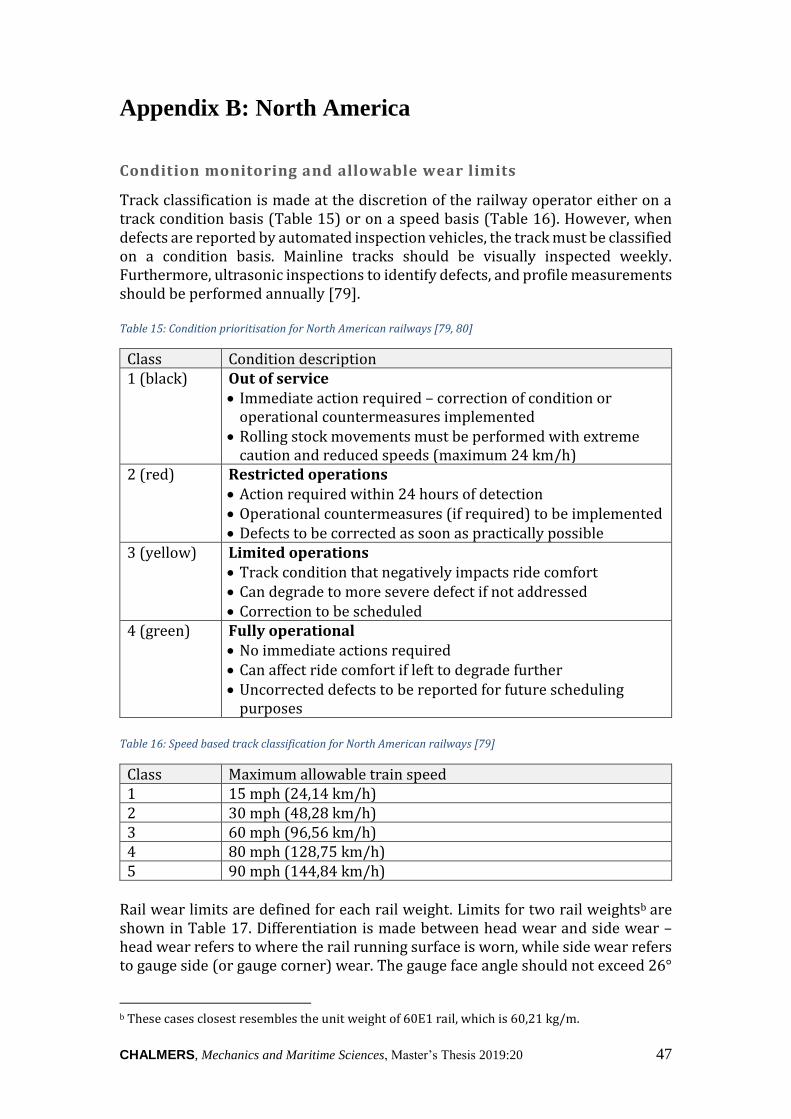
CHALMERS, Mechanics and Maritime Sciences, Master’s Thesis 2019:20 47
Appendix B: North America
Condition monitoring and allowable wear limits
Track classification is made at the discretion of the railway operator either on a track condition basis (Table 15) or on a speed basis (Table 16). However, when defects are reported by automated inspection vehicles, the track must be classified on a condition basis. Mainline tracks should be visually inspected weekly. Furthermore, ultrasonic inspections to identify defects, and profile measurements should be performed annually [79]. Table 15: Condition prioritisation for North American railways [79, 80]
Class Condition description 1 (black) Out of service
• Immediate action required – correction of condition or operational countermeasures implemented
• Rolling stock movements must be performed with extreme caution and reduced speeds (maximum 24 km/h)
2 (red) Restricted operations • Action required within 24 hours of detection • Operational countermeasures (if required) to be implemented • Defects to be corrected as soon as practically possible
3 (yellow) Limited operations • Track condition that negatively impacts ride comfort • Can degrade to more severe defect if not addressed • Correction to be scheduled
4 (green) Fully operational • No immediate actions required • Can affect ride comfort if left to degrade further • Uncorrected defects to be reported for future scheduling
purposes Table 16: Speed based track classification for North American railways [79]
Class Maximum allowable train speed 1 15 mph (24,14 km/h) 2 30 mph (48,28 km/h) 3 60 mph (96,56 km/h) 4 80 mph (128,75 km/h) 5 90 mph (144,84 km/h)
Rail wear limits are defined for each rail weight. Limits for two rail weightsb are shown in Table 17. Differentiation is made between head wear and side wear – head wear refers to where the rail running surface is worn, while side wear refers to gauge side (or gauge corner) wear. The gauge face angle should not exceed 26°
b These cases closest resembles the unit weight of 60E1 rail, which is 60,21 kg/m.

48 CHALMERS, Mechanics and Maritime Sciences, Master’s Thesis 2019:20
[80]. Where only running surface wear is seen, the allowable limits are lower than in cases where both running surface and gauge side wear is present. Wear also causes deviation in the track gauge, which is limited according to Table 18. Table 17: Recommended head and side wear limits (CWR) [80]
Rail weight
Green Yellow Red Black Head wear only
[mm]
Head and side wear
[mm]
Head wear only
[mm]
Head and side wear
[mm]
Head wear only
[mm]
Head and side wear
[mm]
Head wear only
[mm]
Head and side wear
[mm] 132 lb (59,87 kg)
19,1 33,3 22,2 34,9 25,4 41,3 25,4 41,3
136 lb (61,69 kg)
28,6 41,3 30,2 41,3 31,8 44,5 31,8 44,5
Table 18: North American track gauge limits [79]
Track class
Priority Operating speed Deviation from design*
Min Max 1 1 ≤15mph (24,14 km/h) -½ in
(-12,7 mm) +1½ in (+38,1 mm)
2 & 3 2 16 to 60mph (25,75 to 96,56 km/h) -½ in (-12,7 mm)
+1¼ in (+31,8 mm)
4 & 5 3 61 to 90mph (98,17 to 144,84 km/h) -⅜ in (-9,5 mm)
+¾ in (+19,1 mm)
* Operation is not allowed when loaded gauge deviation is less than -½ in or more than +1½ in.

CHALMERS, Mechanics and Maritime Sciences, Master’s Thesis 2019:20 49
Appendix C: Australia
Track classification
Table 19 shows how the Code General Appendix (ETG-01-02) used in South Australia, Western Australia and Victoria classifies heavy tracks (47 kg rail and higher). Type A corresponds to higher risk rails, with generally more stringent remedial actions; case B is the base case [84]. Table 19: Australian track classification [84]
Type A Type B Line type Multiple main tracks Single main track Track alignment Curve radius ≤ 600 m Curve radius > 600 m or
straight Rail support system Sleeper and fastening
system supplying rail restraint equivalent to dog spiked and rail anchored track
Sleeper and fastening system supplying rail restraint equivalent to concrete, steel or timber sleepered track with resilient fasteners
Passenger volumes Average >1000 passengers per day
Average ≤1000 passengers per day
Allowable wear limits
Recorded track inspections measuring the rail profile wear at an interval of maximum 10 m are scheduled for at least once in 6 months on heavy haul lines and once a year on other lines. However, patrol inspections are typically performed on a weekly basis to identify unusual rail wear or other defects that require urgent attention [86].
Figure 29: Measurements for calculating percentage of head loss [86]
The ARTC Track and Civil Code of Practice differentiates between top and side wear in order to establish acceptable wear limits as shown in Table 20. Rail wear is mitigated using risk-based control limits – depending on the rail type and dominant traffic, the allowable rail wear limits differs. The risk is calculated based

50 CHALMERS, Mechanics and Maritime Sciences, Master’s Thesis 2019:20
on the percentage loss of rail head area, while the re-rail limits are defined in terms of the remaining height of the rail head as shown in Figure 29. Table 21 shows the dimensions for new rail sections [86]. Table 20: Rail wear limits on the Australian rail network [86]
Risk control limits Re-rail limits
Allowable percentage
loss of head area [%]
Top wear only
(where <10mm
side wear has
occurred)
Combined top & side wear
(where >10mm side wear
has occurred)
Rail type
(AS)
Load
limits
(TAL)
With less
than
10 mm
wear on
gauge
side
With
over
10 mm
wear on
gauge
side
Remaining
height limit
(mm)
Remaining
height limit
(mm)
Remaining
height limit
(mm)
47 kg/m ≤25 32 % 32 % 24 24 55
25 - 32 - - - - -
50 kg/m ≤25 45 % 32 % 21 21 50/46*
25 - 32 45 % 32 % 21 21 50/46*
53 kg/m ≤25 35 % 35 % 21 23 50/46*
25 - 32 35 % 32 % 23 23 50/46*
60 kg/m ≤25 45 % 40 % 20 24 46
25 - 32 45 % 34 % 24 24 46
* The extended side wear limit (46 mm) can be used if it is confirmed that all risk factors
(Track and Civil Code of Practice Section 1.4.11) were considered and satisfactorily controlled.
These wear locations must be ultrasonically inspected at a maximum frequency of 6 MGT.
When the risk control limit is exceeded, the inspection and maintenance approach is adjusted, additional safety measures (like reduced speed limits) are implemented and it is classified as defects. Once the risk control limit is reached, wear measurements should be taken at a maximum interval of 10 MGT to monitor the rail whilst rail replacement is scheduled [86]. Table 21: New rail dimensions for Australian railways [86]
Rail type New rail head area (mm2) Full height (mm) at 16 mm
47AS 2 548 37
50AS 2 710 39
53AS 2 721 39
60AS 2 999 44
Rail profiling acceptance criteria
The General Appendix to the ARTC Track & Civil Code of Practice (Section 1.7.5.8) describes the acceptance criteria for rail grinding as follows:
• Corrugation: the longitudinal roughness must be measured within a wavelength of 150 mm to 1500 mm. The standard deviation over any rail

CHALMERS, Mechanics and Maritime Sciences, Master’s Thesis 2019:20 51
section of 5 m may not exceed 0,1 mm RMS. Table 22 shows the acceptable percentage of longitudinal irregularities for a reprofiled rail [85].
• No dipped or peaked welds may exceed 0,5 mm in any 1 m section. • All welds in sections where ballast disturbances are seen, must be treated. • There may be no more than 5 impacts of 30 m/s2 or higher per track
kilometre. Table 22: Corrugation tolerances in terms of maximum allowable percentage exceeding irregularities [85]
Wavelength range (mm)
10 – 30 30 – 100 100 – 300 300 – 1000 1000 – 1500
≥53 kg rail 5 % 5 % 5 % 10 % No requirement <53 kg rail 5 % 5 % 5 % 10 % 10 %
Additionally, there is visual acceptance criteria with regards to the rail grinding facets. These facets may not exceed 4 mm on the gauge corner, 7 mm on the field corner and 10 mm within 10 millimetres of the contact band. Furthermore, the facet width over any 100 mm rail section may not vary with more than 25 %. After profiling, the average rail surface roughness may not exceed 15 μm Ra; however within 5 km of residential areas this is reduced to 10 μm Ra [85, 87].
Figure 30: Schematic showing the gauge face angle [94]
Gauge side wear must be monitored to ensure that the gauge face angle (as shown in Figure 30) is within tolerance – excessive wear increases the risk of derailment. For the Australian network, the gauge face angle may not exceed 26° over any 2 m rail section; however, anything above 24° should be reported. Remedial action, such as rail reprofiling, should be taken to reduce the gauge face angle to within the acceptable limits [86]. Rail reprofiling, regardless if it is done as part of corrective or preventive maintenance, must result in a profile that is within 0,2 mm on the contact band of the target profile and 0,4 mm outside the contact band. In order to verify this, the cross sectional rail head profile must be measured after rail profiling at intervals of 20–25 m to an accuracy of 0,1 mm. The allowable tolerances on the profile measurements are shown in Table 23 [85, 87]. Table 23: Rail profile tolerances for Australian railways [85]
In contact zone Outside contact zone 90 % of values below 0,25 mm below 0,45 mm 95 % of values below 0,30 mm below 0,50 mm 98 % of values below 0,35 mm below 0,55 mm

52 CHALMERS, Mechanics and Maritime Sciences, Master’s Thesis 2019:20
Appendix D: Rail transport goals
The EU Commission’s 2011 Transport White Paper has several goals concerning rail transport. The expectation is that mobility should be improved whilst maintaining the EU sustainability targets. This can only be achieved by upgrading the capacity of transport systems throughout Europe for passenger and freight transport, especially for longer distance travel. The 2030 target is to shift 30 % of road traffic over 300 km to other suitable transport modes. By 2050 rail is expected to be the preferable mode of medium-distance travel. This entails a dense rail network between the European Member States. Apart from several administrative and legal obstacles, significant infrastructure development will be required to obtain these goals. Consequently, rail safety will be a major concern and it will be essential to ensure uniform control over the safety certification and maintenance of the single European railway area. EU-funded research is aimed at improving systems for European rail traffic management and rail information systems, and the Commission has committed to develop a common approach with regards to noise and local pollution costs on such a single network by 2020 [70].

CHALMERS, Mechanics and Maritime Sciences, Master’s Thesis 2019:20 53
References
1. Vossloh [Internet]. [accessed 2019 May 12]. Available from: https://www.vossloh.com/en/press/media-and-downloads/press-photos/
2. Lundmark J. Rail grinding and its impact on the wear of wheels and rails. Licenciate thesis. Luleå University of Technology; 2007. 88 pp
3. Zarembski AM. Rail grinding as part of rail maintenance strategy. Railw Track Struct. 2008; vol 104, no 6, pp 55–58
4. Ekberg A and Paulsson B (Eds). INNOTRACK. Concluding technical report. 2014. 148 pp
5. Jovanovic S. Maintenance - the key driver of railway infrastructure costs. SEETO Transport Infrastructure Forum, Transport: A driver of growth [Internet]. Sarajevo; 2016. 43 pp
6. Andersson E, Berg M and Stichel S. Rail Vehicle Dynamics. Stockholm: Railway Group KTH; 2014
7. UIC Leaflet 700 OR. Classification of lines - Resulting load limits for wagons. UIC; 2004. 28 pp
8. CER. Working group report on longer trains - Facts & experiences in Europe. 2016. 81 pp
9. Union guidelines for the development of the trans-European transport network [Internet]. Vol. 348. European Parliament Report REG 1315/2013. 2013. 128 pp
10. Kutz M. Railway track design. Handbook of Transportation Engineering, Volume II: Applications and Technologies, Second Edition, Chapter 20. McGraw Hill Professional, Access Engineering; 2011. 22 pp
11. Esveld C. Modern Railway Track. MRT-Productions; 2014. 723 pp
12. FRA. Track inspector rail defect reference manual. Off Railr Safety, US Dep Transp. Vol 2, July 2015. 71 pp
13. INNOTRACK. D4.5.5 – Guidelines for management of rail grinding. 2006. 20 pp
14. INNOTRACK. D4.5.3 – Fields of improvement in grinding practices as input for LCC evaluations. 2009. 17 pp
15. CEN. EN 13674-1: Railway applications. Track. Rail. Part 1: Vignole railway rails 46kg/m and above. 2002. pp. 107
16. INNOTRACK. D4.5.2 – Target profiles. 2008. 10 pp
17. Liu Y, Yang T, He Z and Li J. Analytical modeling of grinding process in rail profile correction considering grinding pattern. Arch Civ Mech Eng. 2018; vol 18, pp 669–78
18. Tournay HM and Mulder JM. The transition from the wear to the stress

54 CHALMERS, Mechanics and Maritime Sciences, Master’s Thesis 2019:20
regime. Wear. 1996; vol 191, no 1–2, pp 107–12
19. Smith RE and Kalousek J. A design methodology for wheel and rail profiles for use on steered railway vehicles. Wear. 1991; vol 144, pp 329–42
20. INNOTRACK. D4.1.5 – Definitive guidelines on the use of different rail grades. 45 pp
21. Sahay SS, Mohapatra G and Totten GE. Overview of pearlitic rail steel: accelerated cooling, quenching, microstructure, and mechanical properties. J ASTM Int. 2009; vol 6, no 7. 26 pp
22. Olivares O, Garcia CI and Hernández FCR. Metallurgy of high-carbon steels for railroad applications. J South African Inst Min Metall. 2013; vol 113, February, pp 15–7
23. Steenbergen M. Rolling contact fatigue in relation to rail grinding. Wear. 2016; vol 356–357, pp 110–21
24. IN2TRACK. D3.3 – Enhanced inspection, maintenance and operation of track. 2019. 118 pp
25. Ekberg A and Sotkovszki P. Anisotropy and rolling contact fatigue of railway wheels. Int J Fatigue. 2001; vol 23, no 1, pp 29–43
26. Polevoy E and Temlyantsev M. Rational chemical composition and heat treatment models of rails made from E76HF steel using the heat of rolling heating. IOP Conf Ser Mater Sci Eng. 2016; vol 150, no 012030. 8 pp
27. INNOTRACK. D4.4.1 – Rail inspection technologies. 2008. 43 pp
28. Magel E. Validation of Electromagnetic Walking Stick Rail Surface Crack Measuring Systems. US Department of Transportation Report DOT/FRA/ORD-16/23. 2016. 62 pp
29. UIC IRS 70712 - Rail defects. 1st Edition. UIC IRS VII - Way and Works. 2018. 118 pp
30. Sperry Rail Service (compiled by). Rail Defect Manual [Internet]. Michael Sol Collection; 1968. 43 pp
31. Magel EE. Rolling contact fatigue: a comprehensive review. FRA. 2011. 132 pp
32. Personal communication regarding planning of MSc thesis on grinding. Asplund. 2019.
33. Sroba P, Caldwell R, Kalousek J and Harris R. Using predicted defects to manage grinding. Railw Track Struct. 2009; June, pp 53–6
34. Schöch W and Stock R. Strategic rail reprofiling. 11th International Contact Mechanics Conference (CM2018), Delft. Delft, The Netherlands; 2018. 49 slides
35. FRA. Rail profile grinding on high-hardness premium rail at the facility for accelerated service testing. US Department of Transportation; Research results report RR08-19; 2008. 4 pp
36. Sroba P and Roney M. AREMA Committee 4, Sub Committee 9. Rail

CHALMERS, Mechanics and Maritime Sciences, Master’s Thesis 2019:20 55
grinding best practices. Canada; 2003. 63 pp
37. Zarembski AM. The art and science of rail grinding. 1st Edition. Omaha: Simmons-Boardman Books; 2005. 420 pp
38. Transit/switch grinders, RGHC Series catalogue [Internet]. Harsco Rail; 2018.
39. Rail Technology Catalog [Internet]. Linsinger Maschinenbau GmbH; 2018
40. Westerberg M. TDOK 2014:0485. Slipning av räler och spårväxlar. Trafikverket; 2015. 10 pp
41. INNOTRACK. D3.1.5 – Recommendation of, and scientific basis for, optimisation of switches & crossings – part 1 Identifying and Understanding Core S&C Issues. 30 pp
42. Zhe H, Jianyong L, Yueming L, Meng N and Wengang F. Investigating the effects of contact pressure on rail material abrasive belt grinding performance. Int J Adv Manuf Technol. 2017; vol 93, pp 779–86
43. RG400 series rail grinder catalogue [Internet]. Loram Maintenance of Way, Inc.
44. Lin B, Zhou K, Guo J, Liu QY and Wang WJ. Influence of grinding parameters on surface temperature and burn behaviors of grinding rail. Tribol Int [Internet]. 2018; vol 122, no February, pp 151–62
45. Wang H. Grinding and milling. (2019-03-04). Personal communication with Björn Paulsson
46. Zarembski AM and Hagan B. Effectiveness of high speed rail grinding on metal removal and grinding productivity. AREMA Railway Interchange. 2011. 53 pp
47. Bremsteller J. Presentation on high speed grinding. Ceske Budejovice: Vossloh; 2013
48. High speed grinding train (HSG-2) Catalogue [Internet]. Vossloh; 2019
49. AUTOMAIN. D4.1 – Improvements analysis for high performance maintenance and modular infrastructure. 2013. 65 pp
50. Hartleben D. Mobile schienenbearbeitung in gleisen und weichen mittels drehhobeln. EI-Eisenbahningenieur. 2013; September, pp 1–6
51. Pan C, Zhang J, He Y, Xia H and Wang B. Simulation study on high-speed milling performance of rail U71Mn material. Proc 3rd Int Conf Electr Inf Technol Rail Transp. 2017; vol 483, pp 967–74
52. Kubin W, Daves W and Stock R. Analysis of Rail Milling As a Rail Maintenance Process : Simulations and Experiments. Proceedings of the 11th International Conference on Contact Mechanics and Wear of Rail/wheel Systems, CM 2018. Delft, The Netherlands; 2018. pp. 480–6
53. Stock R, Kubin W, Daves W and Six K. Advanced maintenance strategies for improved squat Mitigation. Proceedings of the 11th International Conference on Contact Mechanics and Wear of Rail/wheel Systems, CM 2018. Delft, The Netherlands; 2018. pp. 932–7

56 CHALMERS, Mechanics and Maritime Sciences, Master’s Thesis 2019:20
54. Conventional milling VS Climb milling [Internet]. Technical Resources. Harvey tool company; 2017
55. Fröhling R and Mark T. Wheel-rail interaction: maintenance design. Presentation. Transnet; 2010. 25 slides
56. Singleton R, Marshall M, Lewis R and Evans G. Rail Grinding for the 21st century - taking a lead from the aerospace industry. Proc IMechE Part F J Rail Rapid Transit. 2013; vol 229, no 5, pp 457–65
57. High performance milling train (HPM) catalogue [Internet]. Vossloh; 2019
58. Hartenstein M. Compact miller targets a mix of applications. Railway Gazette International. 2018, Aug. pp 50–2
59. High performance rail milling machine (HSM) catalogue [Internet]. Schweerbau; 2018
60. Uhlmann E, Lypovka P, Hochschild L and Schröer N. Influence of rail grinding process on rail surface roughness and surface layer hardness. Wear. 2016; vol 366–367, pp 287–93
61. JSA. JIS B 0601: Surface roughness. 2001. 3 pp
62. Evans G. STRABAG Rail milling RRV stage 2 trials 2011. Sponsor ’s report nr PA05 _ 04868. 2012. 79 pp
63. Mackenzie DS. Metallurgical reasons for grinding cracks and their detection. gearsolutions.com. 2017; May, pp 1–4
64. Smith WF and Hashemi J. Foundations of Materials Science and Engineering. Fourth Edition. McGraw Hill; 2006. 223 pp
65. High speed grinding machine (HSG-city) datasheet [Internet]. Vossloh; 2019
66. Meierhofer M and Pohl R. Head check measurement - a fully-operational system on a rail grinder. World congress on railway research, Montreal Canada. 2006. 7 pp
67. Ekberg A and Kabo E (Eds). Surface fatigue initiated transverse defects and broken rails – an international review. Chalmers University of Technology; CHARMEC. 2014. 24 pp
68. The World Factbook [Internet]. Central Intelligence Agency. [accessed 2019 May 16]. Available from: https://www.cia.gov/library/publications/the-world-factbook/rankorder/2121rank.html
69. Frick A (UHabv). TDOK 2014:0074. Teknisk specifikation för slipning av räler och spårväxlar. Vol. 2.0. Travikverket; 2014. 20 pp
70. European Commission. White Paper on transport — Roadmap to a single European transport area — Towards a competitive and resource-efficient transport system. Luxembourg; 2011. 32 pp
71. CEN. EN 13231-3: Railway applications. Track. Acceptance of works. Acceptance of reprofiling rails in track. 2012. 39 pp

CHALMERS, Mechanics and Maritime Sciences, Master’s Thesis 2019:20 57
72. Canadian Pacific [Internet]. 2019 [accessed 2019 Apr 23]. Available from: www.cpr.ca/en/safety/rail-regulations
73. Rail trends. RAC Annual report on the performance of Canada’s railway industry. 26th Edition. Ottawa: RAC; 2018. 38 pp
74. Rail Transportation, Government of Canada [Internet]. 2012 [accessed 2019 Apr 23]. Available from: http://www.tc.gc.ca/
75. DeVries R, Sroba P and Magel E. Preventive grinding moves into the 21st century on Canadian Pacific Railway. Proceedings of the AREMA 2001 Annual Conference. Chicago, Il.; 2001. 15 pp
76. Magel E and Sroba P. Managing the wheel–rail interface: the Canadian experience. Wheel-Rail-242. 2009. 17 pp
77. Freight rail works for America. Information leaflet. AAR; 2017. 2 pp
78. Stanford J, Magel E and Sroba P. Transitioning from corrective to preventive rail grinding on the BNSF railroad. Confronting the Barriers of Heavy Haul Rail Technology: Proceedings, 7th International Heavy Haul Conference. National Research Council Canada; 2001. 10 pp
79. Rail Transit Fixed Structures Inspection and Maintenance Working Group. Rail Transit Track Inspection and Maintenance. Washington; Report APTA RT-FS-S-002-02, Rev. 1. 2017. 97 pp
80. FTA. Pocket Guide: compilation of rail transit industry best practices for track inspection and maintenance. U. S. Department of Transportation; 2010. 128 pp
81. Sweeney S. Companies pledge to deliver rail milling machine to North America by the end of 2019 [Internet]. [accessed 2019 Apr 29]. Trains. 2018. May. Available from: https://trn.trains.com/news/news-wire/2018/05/01-company-pledges-to-deliver-rail-milling-machine-to-north-america-by-the-end-of-2019
82. Heavy haul, intermodal and freight rail report. Australian Trade Commission; 2013. 40 pp
83. Avery R. Trainline 6 Statistical report of the Department of Infrastructure, Regional Development, and Cities. Canberra, Australia: Australian Railway Association; 2018. 168 pp
84. ARTC - Track and Civil Code of Practice -Section 1: Rail - General Appendix Management of Rail Defects. ETG-01-02. Australian Rail Track Corporation Ltd; 2013. 10 pp
85. ARTC - Track and Civil Code of Practice . Rail Reprofiling Standard for Plain Track. ETM-01-02. Australia: Australian Rail Track Corporation Ltd; 2015. 29 pp
86. ARTC - Track and Civil Code of Practice -Section 1: Rail. Australia: Australian Rail Track Corporation Ltd; 2016. 43 pp
87. ARTC - Track and Civil Code of Practice -Section 1: Rail - General Appendix. ETG-01-01. Australia: Australian Rail Track Corporation Ltd; 2011. 12 pp
88. Mundrey J. Indian railway tracks – a track engineering compendium. 5th

58 CHALMERS, Mechanics and Maritime Sciences, Master’s Thesis 2019:20
Edition. Wingler F, editor. India: Drwingler railroad modelling & consutancy; 2018. 644 pp
89. Technical Specification for Grinding Service by Railbound Vehicle. Israel Railways LTD; Report No. E-06-0004. 2015. 36 pp
90. Takikawa M. Innovation in Railway Maintenance utilizing Information and Communication Technology (Smart Maintenance Initiative ). Japan Railw Transit Rev. 2016;, no 67, pp 22–35
91. Railway in Sweden and Japan – a comparative study. Memorandum of cooperation report (2014:12). Transport Analysis; Report 2014:12. 2014. 80 pp
92. Aveng Rail [Internet]. Transnet Rail Profiling Pamphlet. p 1
93. Alexander Forbes Risk Services. Annual Contract Works and Public Liability - Insurance Policy. 2006. 25 pp
94. Government of South Australia - TransAdelaide Infrastructure Services. CP-TS-961. Code of Practice - Train system [CP2]. Transadelaide Infrastructure Services. 2008. 58 pp