Radio Exp nter - Iet LabsNEW T ESTING INSTRUMENTS FOR THE RAD IO SERVICE LABORATORY IN its exhibi t...
8
TheG Exp VOL. IV, No. I Radio nter J UNE, 1929 PR ODUCT1 0N T ES TI NG OF AU D lO -FRE Q. UENCY AMl' L1 FlERS 'By ART H UR E. THIESSEN H O\\'EVER mueh engineering de- vdopmcnt the manufacturer of an audio-frequency ampli_ fier expends on its design, there remains the problem of comparing the perform_ ance of the quantitr-produced unit with that of the laboratory model. Wit hout rigorous i nspectioll some defective units are likely to reach the user, which makes necessary expensive replacements and breeds ruinous ill ..... ill. Some manufacturers check the com- ponent parts l>efore assembly and follow this with a supplementary "trv·it-and-see.if.it-works" test. This, is only partially satisfactory because errors in assembly may still creep in and because any kind of a tTial inspection requires highly-com- petent, specially-trained inspectors if the tests are to mean anything. Even then, it is doubtful whether any listen- ing test can be relied upon to detect small abnormalities in the performance of a high-quality amplifier under pro- duction conditions. When preparing to manufacture their new radio receivers, the Victor Talking Machine Company realized the importance of thorough inspection and the limitations of the usual methods. T hey asked the General Radio Company to build suitable test equipment, and the engineering de- partments of the twO organizations collaborated on the design of the audio- frequency amplifier t.est set that is described here. It makes possible a speedy and accurate test and is capaule of operation by an inspector with no special training. The most imponanr characteristics of an amplifier's performance are its ability to show the required amount of gain or amplification over the de- sired frequency range and to deliver the required amOUllt oj power without overloading. It was decided that the test of the Victor Company's amplifiers should include an accurate measure- ment of both these quantities. T he method chosen for making the test for gain is based upon one some- times used for making measurements in the laboratory. Figure I shows it in schema tic form .. <\ n oscilla tor opera ting at the test frequency supplies energy through a calibrated attenuation net- work to the amplifier, in the output circuit of which is connected a suitable load and a meter for measuring the voltage drop across it. The network is adjusted until the voltage across the load is equal to that measured across [ • J IET LABS, Inc in the GenRad tradition 534 Main Street, Westbury, NY 11590 www.ietlabs.com TEL: (516) 334-5959 • (800) 899-8438 • FAX: (516) 334-5988
Transcript of Radio Exp nter - Iet LabsNEW T ESTING INSTRUMENTS FOR THE RAD IO SERVICE LABORATORY IN its exhibi t...

TheG Exp
VOL. IV, No. I
Radio nter
J UNE, 1929
PRODUCT10N T ESTING OF AU DlO-FREQ.UENCY AMl'L1FlERS
'By ART H UR E. THIESSEN
H O\\'EVER mueh engineering devdopmcnt the manufacturer of an audio-frequency ampli_
fier expends on its design, there remains the problem of comparing the perform_ ance of the quantitr-produced unit with that of the laboratory model. Without rigorous i nspectioll some defective units are likely to reach the user, which makes necessary expensive replacements and breeds ruinous ill ..... ill.
Some manufacturers check the component parts l>efore assembly and follow this with a supplementary "trv·it-and-see.if.it-works" test. This, ho\~'ever, is only partially satisfactory because errors in assembly may still creep in and because any kind of a tTial inspection requi res highly-competent, specially-trained inspectors if t he tests are to mean anything. Even then, it is doubtful whether any listening test can be relied upon to detect small abnormalities in the performance of a high-quality amplifier under production conditions.
When preparing to manufacture their new radio receivers, the Victor Talking Machine Company realized the importance of thorough inspection and the limitations of the usual methods. T hey asked the General
Radio Company to build suitable test equipment, and the engineering departments of the twO organizations collabora ted on the design of the audiofrequency amplifier t.est set that is described here. It makes possible a speedy and accurate test and is capaule of operation by an inspector with no special training.
The most imponanr characteristics of an amplifier's performance are its ability to show the required amount of gain or amplification over the desired frequency range and to deliver the required amOUllt o j power without overloading. I t was decided that the test of the Victor Company's amplifiers should include an accurate measurement of both these quantities.
T he method chosen for making the test for gain is based upon one sometimes used for making measurements in the laboratory . Figure I shows it in schema tic form .. <\ n oscilla tor opera ting at the test frequency supplies energy through a calibrated attenuation network to the amplifier, in the output circuit of which is connected a suitable load and a meter for measuring the voltage drop across it . T he network is adjusted until the voltage across the load is equal to that measured across
[ • J
IET LABS, Inc in the GenRad tradition
534 Main Street, Westbury, NY 11590 www.ietlabs.com
TEL: (516) 334-5959 • (800) 899-8438 • FAX: (516) 334-5988

, TilE GE'I:'EkAL RADIO EXPt: RIMES"TER
th e input terminal s of the network. Then , if all the terminal impedances between units in the circui t h3\'e been properlr matched,· the gain of the amplifier is equal to the attenuation or loss in the network. The comple te gain-frequenc}' characteristic is obtained by repeating this measurement at as many [cst frequencies as necessary.
FrCIiJlE J. Outline chart and power level di~i!r~m for the gain_musuring ~thod u~ed in the amrJilier relll 5(',. All impMnnces an: :&$Sumed
10 be matched
The overload-level tes t is also based upon a laboratory method for determining where further increases in rhe input of the amplifier fail to produce proportional increases in the power out pu t. The overload level is th e ra tio (expressed in decibels) of this power output to the standa rd reference le\'el or normal test outputt of 50 milliwarts.
The audio test panel s as construcred are shown in the schematic diagram of Figure 2. A Hartle}' oscillator delivers voltages at each of fi ve selected frequencies (-+0 , 100, 400, 2500, and 6500 cycles) covering the audio-fn:quency band. At each of these (re-
"This r«juircmenr makes nectS$Rty th~ im_ ped~nC'C Z. If the oscillator outpu t vult age I.e maintained conMMlt a~ Jhown by the "olt_ mcter, the net .... ork bcha"cs :u though it .... ere working OUt of a power source of con~tant in. ternal clccltomotive fon:e :lnd internal im_ ~anC'C Z. 5.!e K. S. J ohnson, 'fr<4ns".ilSi~n Cirrui/J jllr 'fr/(phon;c COlflmll";tlIlirm (New York: I). Van Nostrand Co., 19z5), Chap, .. r VI II , in particular.
t I. R. E. Standard. Stc rfIU Boo~ ~j tk Inmtulr oj Radio £"l;IIurs (Kcw York, 'g!rj),
p. '07·
quencies the voltage o( the oscill ator is made the same by an adju stment of the respective feedback resistances.
From the s tandpoint of the in. ~pector using the test ~et , it is desirable that rhe power Outpu t o ( th e ampl ifi er rn:. constant at everr one of the test frequen cies, in spite uf the (act that the amplifier gain is different for each one. Thcn it is only necessary for him to notc whClher or not the load voltmeter devi;nes from a fixed value marked upon the dial in order to tell whether or not the amplifier is up to standard. This is accomplished by inserting enough attenuation ahead of the amplifier to make the output the same at each frequency. Th is is the function of the compen sation network shown in Figure '2. Both the frequency change and the throwing in of the proper compensation network are made by means o( the large hand· wheel at the le(t of the panel shown in Figure 3 .
An alternating-current--Operated vacuum-tube voltmeter is used to measure th e voltage across the load and to check occasionally the out pu t voltage ofothe oscillator. It is suffi ciently sen. sitive to indicate deviations of am· plifier gain from normal hy as little as aile or two decibels. T he voltmeter is the olle ill the center of the panel.
The input and output network s (or making the overload_level test are controlled by the other hand-w heel. As its pointer is moved from left to right ill ten successive steps, an at· tenuation of two decibels per step is inserted ahead of the ampli fier, and, simultaneollslv, the same amount is removed frOl~ the output circuit. So long as the amplifier is operating below its overload level, the reading of th e voltme ter remains fixed, but, when overload occurs, furt her increases of in put fail to produce proportional increases in the output power. Thus, t.he overload level is indicated wh en the
IET LABS, Inc in the GenRad tradition
534 Main Street, Westbury, NY 11590 www.ietlabs.com
TEL: (516) 334-5959 • (800) 899-8438 • FAX: (516) 334-5988

VOL. l V, No. I .1
I:u:;uu; z. Schematic diagram of t"e Te~1 pand for m~king npid mcasurements of gam and overload lel'cl in mmpliliers
output voltage begins to drop off as the test switch is advanced.
In testing an amplifier under working conditions, it is merely necessary to connect it to the test panel by means of a set of fl exi ble leads. \\'ith the over· load. level swi tch set at zero the gain test is mad e at each of the five test frequencies, and. if the reading of the output voltmeter does lIot deviate from standard by more than a specified tolerance, the amplifier has been shown to have a gain. frequency characteristic like that of the laboratory model. The next step is to set the frequency control at some point - 400 cycles, for example - and to ad vance the over· load-level switch until th e output volt· 3ge begins to fall off. The sening of the switch where thi s occurs indicates in decibels the overload level of the am· plifier referred to the reference level.
FtOI:I.E.1. The audio. amplifier test "t as built by the Genera] I(~ dio Compan) for the Viclor Talking Machinc Company
At the extreme lower right of the panel, next to the toggle switch for controlling the power supply to the test set, may be seen two key switches. One o( these throws the voltmeter from the amplifier output circuit to the out· put o( the oscillator for checking its voltage.
Since the audio amplifier is in. tended ior use in conjunction with a phonograph pi ck up (low impedance) as well as the detector tube of the radio receiver, its input circuit has a low. as well as a high-i mpedance winding. Gain and o\'erload·level tests are nude for each winding, and the second key switch makes the necessary internal changes in the test panel.
By means of this extremely rapid check practically all or the possible errors in constrllction will have been shown up. \\'hen the fir st production.
IET LABS, Inc in the GenRad tradition
534 Main Street, Westbury, NY 11590 www.ietlabs.com
TEL: (516) 334-5959 • (800) 899-8438 • FAX: (516) 334-5988

THE GEN"ERAi. R ADID EXPERIMEsn:1t
built amplifiers were being tested, several were found to ha\'e a sub-normal amount of gain in the middle of the frequency band. Checking them upon the elaborate laboratory gainmeasuring set proved that the test panels were operating correctly, but the trouble could not be traced to any fault in the amplifier until it was <.ii~ co\'ere<.i that the lower-grade wax used for impregnating the poWer transformers had been in advertently used in the inter-stage coupling transformers. It is highly probable that a simple listening test would not have found the trouble, ret the accident is one that could happ·en in any assembly plant.
13 )' the use of the General Radio Company's test panels, the Victor Company makes its production with great speed and accuracy and with a conse(luently low unit cost of test. The an!ragc time necessar~ for a complete check is about one minUTe, and the amount of deviation from standard is held to a tolerance of one and one. half decibels. This test compares favorabh in llccuracv with the more elaborate laboratory rneasurcl11cnts re<]uiring considerably more time, equip-
ment, and technical skill. Such high accuracy is justified, for th(:re is no excuse for the manufacturer making heavy ill\'estments in r(:search and quali·[)' materials unless he is sure that th(: finished amplifier is as good as the approved laboratory model.
I n addition to the check lIpon the completed amplifier, all of the com· ponent raw materials are tested before assembly. All input, interstage, and output coupling transformers are inserred in amplifiers of known excellence which are then tested on the test panel. If the amplifier shows normal performance, th(: transformers are shown to be satisfactory.
Ten of these amplifier test panels have been bu ilt for the Victor Company and five more are now in process.
The flexibility of the test se t makes it adaptable for use with almost any audia-frequency amplifier, and it mar be readih' altered to take care of such changes ;n the design of the amplifier that may be made after production has begun. Tht: method of working out the problem is gellt:ral enough to showdefinitelr that laboratory methods c~n successfully be applied to prod uction tests.
F[(ll;lUt ~. Four o( the six audio.amplifier test p:lnelJ as used by the Victor ComP;InY fOl" nl:lking production inspection tesu 011 completed amplifiers
IET LABS, Inc in the GenRad tradition
534 Main Street, Westbury, NY 11590 www.ietlabs.com
TEL: (516) 334-5959 • (800) 899-8438 • FAX: (516) 334-5988
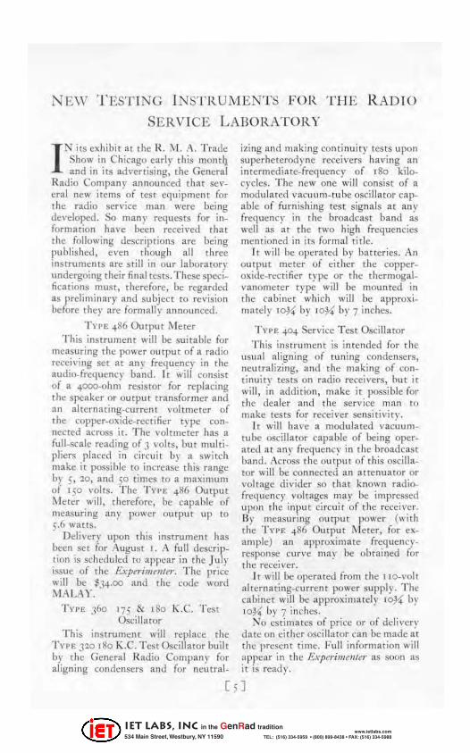
NEW T EST ING INSTR UMENTS FOR T HE R AD IO
SERVICE LABORATORY
I N its ex hibi t at rhe It . i\ 1. A. T rade Show in Chicago earlr rhis mondl and in its ad\'ertising, the General
Radio Compan~' announced that several new items of tcSt equipment (or the radio service man weTe being developed. So Illan)" requests for in_ formation have been recei\'ed that the following descriptions arc being published, even though all three insrrulllelHs atC sti ll in our laboratory undergoing their final tests. These specifications must, therefore, be regarded as preliminary and subject ro revision before they arc formally announced.
1'",,£ .. 86 Omput ~'I eter
This instrument will be suitable for measuring the power output of a tlldio receiving set at any frequency in the audiO-frequenq' band. I t will consist of a -+ooo-ohrn resistor for replacing the speaker or output transformer and all alternating-current voltmeter of the copper-Oxide-reetifier type connected across if. The \·olrmeter has a full-scale reading of 3 volts, but multipliers placed in circuit by a switch make it possible to increase this range b) 5, 20, and 50 times to a m3)(imum of 150 \'olts. The '1'",'£ 486 OutpU t ~"' eter will, therefore, be capable of measuring any power output up to 5.6 waus.
Delivery upon this inStrwl1enl has been set for August I. A fuJI description IS scheduled to appear in the J uly issue of the E.\·pu;mtnln·. The pricl:" will be ~34.00 and the code word MA LA,Y.
T YPE 360 175 & ISO K.C. T est OscillittOr
Th is instrument will replace the TYPE 320 180 K .C. T estOscilJator built by the General Radio Company for aligning condensers and for neutral-
izing and mak ing continuity tests upon superheterod yne receivers having an intermediate_frequency of 180 kilocycles. T he new one will consist of a modulated vacuum-tube osci lla tor capable of furni shing test signals at an~' frequenc~' in the broadcast band as well as at the t\\'O high freq uencies mentioned in its form al title.
I t will be operated by batteri es. An outpu t meter of either l he copperoxide-rectifier type or the thermogalvanometer type will be mounted in rhe cabinet which wi ll be approxi_ mately 10~ by l OX" by 7 inches.
T nI'. 404 Service T est OscilJaror
This instrument is intended for the IIsunl aligning of tuning condensers, neutralizing, and the making of cont inuity tests on radio receivers, bu t it will, in addition, make it possible for the dealet and the service man to make tests for receiver sensitivity.
I t will ha\·e a modulated vactlumtube oscillator capable of being operated at an)" frequency in the broadcast tJand. Across the Outpu t of this oscillator will be connected an attenuator or voltage divider so that known radiofrequency voltagcs may be. impressed upon the input ci rcuit of the receiver. By measuring output power (with the T\'PE 486 Output ~ l erer, for example) an appro)(im:n c frequencyresponse cun'c may be obtnined for the receiver.
It will be operated from the II D-voh alternating-t'u rrent power supply. The cabinet will be appro)(;mately loy.' by 1O~ by 7 inches.
::-.10 estimates of price or of deli\"er~' date all either osci llator can be made;1,[ the present time. Ful l information will appea r in the /!..\'perimeIiJer as soon as it is ready.
[ll
IET LABS, Inc in the GenRad tradition
534 Main Street, Westbury, NY 11590 www.ietlabs.com
TEL: (516) 334-5959 • (800) 899-8438 • FAX: (516) 334-5988

DIRECT-CURRENT AMPLIFI ER D ESIGN
~y C H AR LE S E. \NORTHEN
XMEANS of magnifying the inren_ sity of slowly_varying voltage pulses ;s often needed in ex
perimental work. Amplifiers for television and for vacuum_tube volt_ meters must respond to low frequencies and to direct current (zero cycles per second), but the usual types of audio... frequency amplifiers are not suitable because they do not operate effect ively at frequencies much below '25 cycles per second.
Although there is nothing partictllady new about a direct-current amplifier, we are describing here one 01 twO stages built by the General Radio Company, because it presents an in_ teresting example of amplifier design (see Figure I). It was to be used in conjunction with all electrocardiograph, an instrument used by the medical prafession in the study of heart action. During the heart beat potential differences of the order of a few milli\'olts appear between active and inactive heart muscle. These voltages are applied to the input of an amplifier and
passed on to :an Einthoven (srring_ type) galvanometer for recording . .. From the schematic diagram of Figure 2 it mar be seen that this amplifier is of the resist:allce-coupled type in which the grids of the v:aCUltm tubes are held at the proper operating potential by means of batteries inste:ad of the usual blocking condensers and grid leaks. With no signal voltage applied across the input terminals, each tube is operating at a suitable point on the linear portion of its grid_voltage plate_current characteristic. A voltage applied to the grid of the first tube causes a change in its place current which, in turn, produces a change in the voltage drop across the plate resistor HI and alters the grid bias of the second tube. Thi s prorluces a change in the plate current of the second tube and a change in the voltage across the output circui t. .'\ scheme for balancing out the stead y plate current of the second tube in the output circuit is provided. I t will be described latet.
If the proper operating points have
/ ,
, A "
• ,
, l"
,," , ~ .. ~ 1 " , • ,-;-
• r-o. , ~, .' " ... ~" , A •
":.~." • , " .. ~~« ..
~ @ ~ ~ '" 0;> -" FIGURE f. A fWO-stage dirccl_currcnt amplifier, a piece of special equipment buill by
the General Radio Company
[6 J
IET LABS, Inc in the GenRad tradition
534 Main Street, Westbury, NY 11590 www.ietlabs.com
TEL: (516) 334-5959 • (800) 899-8438 • FAX: (516) 334-5988

TIIF. GE N E RAl. RAmo E XP ERI!oIENTER )
<.
FICUll£ l . Circuit diagram of the direct.eurrcnt aml'lifier of Flcu~£ I
been chose n, the change in plate voltage in each tube is greater than rhe grid vol tage change. The amount of this amplification depends upon the value of plate resistors used as well as upon the operating poi nts chosen. The over-all ampl ification will, in general, be less than the product of th e amplification factors of the tubes. It should also be noticed that successi ve voltage changes are out of phase by 180 degrees. If the change on the grid of the first tube be in a posi tive direction, that on the second grid is in the nega_ tive direction. Th is fact might be an important consideration when deciding whether an amplifier should consis t of an even or an odd number of stages.
The considerations involved in th e design of a di rect-current amplifier can be better understood by means of the graphic analysis o( Figure 3. This analysis holds onl}' (or small values o( applied voltage on tubes hiased to operate on the linear portions of their characteristics. The grid-vol tage-platecurrent characteristics are pl otted as shown, that of the second tube being to the right o( and ahove the first. If the two operating points are A and C, lines drawn (rom these points perpendicular to the axes will intersect at B.
For a given value of RI, the drop across it is I R}R,. Through S , then, draw a line in tersecting the voltage
axis at an angle eq ual to ,
tan -I _ . R,
From the geome try of the figure it is chen evident thac the dis tance subtended by this line on the voltage axis is eq ual to I fJl) RI • Since this gives the grid o( th e second tube too large ;\ nega ti,'e bias, the battery £: suppli es enough positi ve bias to hring the grid to the selected operating poi nt. !leferring again to the d iagram, it may be seen that E,- l fJI)R,=E".. T his gra_ phic analysis makes it possible to stud ), the effect o( changing the values of the batteriesando( RI • I t isextrcmelyuseful in designing di rect-current amplifiers.
I n order that no current shall Row in the output circuit except when a voltage is appli ed [Q the input, the steady plate current in the second tube
$(:(I)ND
/ I - , ,
i!j ~< • I ,
''0.
nu, / >Ok I
, I • I , -..;t.'. I j ~ I ,
~r~ .... • Flouu: J. Graphic ilRlIlrsis for " t .... ()..slagt!
direct-eurrcnl anlriifier
is balanced out. !leferri ng to Figure 2,
the balancing resistor R2 is made equal to the plate resistance o( the second tuhe , and the balanci ng battery E~ is made equal to the battery E~. Under th ese conditions, no voltage appears across the output ci rcuit unl ess one is applied to the inpu t . . -\ 7.ero..center galvanometer is provided in the instrument (or indica ting the balance condi tion.
IET LABS, Inc in the GenRad tradition
534 Main Street, Westbury, NY 11590 www.ietlabs.com
TEL: (516) 334-5959 • (800) 899-8438 • FAX: (516) 334-5988

r- IISC ELLANY
W ITlI thi s number, t he fir st of Volume IV , t he General Radio £.v:perime11ler appears in a new
format. The new page is only one.ha lf as large as the old one (6 inches by 9 inches instead of 9 inches by 1'2 inches) , but doubling the number of pages makes it possible to include as much material as before.
" Wit h an input of r 5 db at 30 cycles the inductor motor moves a ten_i nch cone one-eighth inch." (11) " ' n all [of the author's] loud-speaker response cur ves, the sou nd in tcnsi n ' in db was plotted against frequenc)','"
T he decibel is. b)' defini tion, a measu re of a ratio between two
amount:> of power, Besides making it easier to handle. the sm aller size brings the E'\'perimcn/er more n early into un iformity with other publicatiolls which the reader keeps for reference.
' 0 other radical changes ei ther in the editorial or the distribution policies :uc co n tern plated. There is no sub. scri ption fet:. and we ask only that our reader!; express a desi r e to co ntinue
CONTR IBUTORS
BOTH contributon to this issue of the E1rperimenter
are members of the General Radio Company's Engineering Department:
ARTHUR E. THIESSEN , Bachelor of Engineering. Johns Hopkins Univenity, 1926. 1926- 1928. Bell Telephone Laboratories, Inc. 1928 to date, E ngineering Department, General Radio Company.
CHARLES E. WORTHEN. Bachelor of Science, Massachusetts Institute of TechIlology, 1928. 1928 to date, Engineering Department, General Radio Company.
the number of decibel s correspondi~g to a power ratio being given by db =
[ 0 logl"", where,. is the ra tio. O\}\'iollsl y. specifying a power input or an intensi ty of sound in decibels is as devoid of meaning as the sta tement that t he power inpu t to a motor is 95 per cent. We admit, however, th a t" decibel" does so un d more ImpreSSIve.
I t is possi ble, of
upon the mailing li st by returning the {'atd sen t out once each year. TI, is year's card witt go out sometime duri ng the summer.
course, to express 311
amount of power as so many decibels "abO\'e" or "below" a specified amount of power called the zero or reference level, but so many different reference levels are in use that it is alwavs well to state which one is being us~. I n~ elud ing it takes onl)' a little more dfort on the part of the author and greatly minimizes t he chance of misleadi ng the reader.
• • • • T he following excerpts Irom recent
issues of one of the popular magazines a rouse us sufficientl), to suggest t ha t their editors encourage contri butors to show more respect for the decibel: (a)
T he General Radio E1rperimenter is published monthly to furn ish useful infonnation about the radio and electrical laboratory apparatus manufactured by the General Radio Company. I t is sent without charge to interested persons. Requests should be addressed to the
GENERAL RADIO COMPANY CAMBRIOOE A, M ASSACH USI'!:TTS
[ 8 ]
IET LABS, Inc in the GenRad tradition
534 Main Street, Westbury, NY 11590 www.ietlabs.com
TEL: (516) 334-5959 • (800) 899-8438 • FAX: (516) 334-5988