

Radar Theory for Area Approach Radar Controllers
37
description
Radar Theory for Area/Approach Radar Controllers
Transcript of Radar Theory for Area Approach Radar Controllers

RRaaddaarr TThheeoorryy FFoorr AArreeaa //AApppprrooaacchh CCoonnttrroolllleerr
ZZUULLFFIIQQAARR AALLII MMIIRRAANNII
SSeenniioorr EElleeccttrroonniiccss EEnnggiinneeeerr
CCiivviill AAvviiaattiioonn AAuutthhoorriittyy –– PPaakkiissttaann

TABLE OF CONTENTS
1.1 Introduction
1.2 Basic Principles : Radio waves Radio wave propagation Radio wave characteristics Velocity, Time and Distance relationship Microwaves Radio System Basics
1.3 Radar : Principle of Operation Range determination in Radar Types of Radar
o CW Radar o FM Radar o Doppler Radar o Pulse Radar
Standard Radar Frequencies and Wave Length 1.4 Basic Pulse Radar System
1.5 Types of ATC Radar : Primary Radar Secondary Radar
1.6 Use of Radar:
1.7 Standard Radar Frequencies and Wave Length
1.8 Primary Radar : Primary Radar Construction: General Block Diagram System Operation Primary Radar Indicator Evaluation of Radar Echoes to Identify Targets Moving Target Indicator (MTI)
1.9 Main Characteristics of Primary Radar : Pulse Repetition Frequency Strikes per scan Scan Rate Beam Width Pulse Width Range Resolution Sensitivity Time Control (STC) Blind Speed

1.10 Radar Equation
1.11 Factors Affecting Radar Performance
1.12 Secondary Radar: Secondary Radar SSR Composition Principle Of Operation Operating Frequencies Interrogation Modes of Transmission Reply (from Transponder) Code nomenclature
1.13 SSR Mode – S
1.14 Comparison of Primary and Secondary Radars
1.15 Radar Display System General System Configuration Functions of RDS Components System Inputs received from radar head Modern Radar Display system
1.16 Siting of radars

RRaaddaarr TThheeoorryy ffoorr AArreeaa//AApppprrooaacchh RRaaddaarr CCoonnttrroolllleerrss
1/33
1.1 Introduction RADAR is an acronym for RAdio Detection And Ranging. As it was originally conceived, radio waves were used to detect the presence of a target and to determine its distance or range. Before RADAR could be born, scientists first needed to understand the principles of radio waves. British physicist James Clerk Maxwell developed equations governing the behaviour of electromagnetic waves in 1864. Inherent in Maxwell‟s equations are the laws of radio-wave reflection, and these principles were first demonstrated in 1886 in experiments by the German physicist Heinrich Hertz. In 1887, he found that radio waves could be transmitted through different materials. Some materials reflected the radio waves. He developed a system to measure the speed of the waves. The data he collected, and the information he uncovered, encouraged further scientific investigation of radio. Experiments of Maxwell and Hertz were the foundation for the development of radio communication, and, later, RADAR. Some years later a German engineer Chistian Huelsmeyer proposed the use of radio echoes in a detecting device designed to avoid collisions in marine navigation. The first successful radio range-finding experiment occurred in 1924, when the British physicist Sir Edward Victor Appleton used radio echoes to determine the height of the ionosphere, an ionized layer of the upper atmosphere that reflects longer radio waves. The first practical radar system was produced in 1935 in England by Sir Robert Watson-Watt (a Scottish origin physicist) By the 1940s, and the outbreak of World War II, the first useful RADAR systems were in place. Germany, France, Great Britain, and the United States all used RADAR to navigate their ships, guide their airplanes, and detect enemy craft before they attacked. After the close of World War II, radar assumed a major role in civil aviation.
RRaaddaarr TThheeoorryy ffoorr AArreeaa//AApppprrooaacchh RRaaddaarr CCoonnttrroolllleerrss
2/33
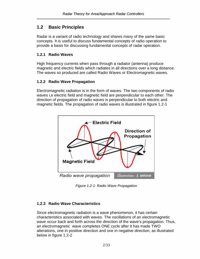
1.2 Basic Principles Radar is a variant of radio technology and shares many of the same basic concepts. It is useful to discuss fundamental concepts of radio operation to provide a basis for discussing fundamental concepts of radar operation. 1.2.1 Radio Waves High frequency currents when pass through a radiator (antenna) produce magnetic and electric fields which radiates in all directions over a long distance. The waves so produced are called Radio Waves or Electromagnetic waves. 1.2.2 Radio Wave Propagation Electromagnetic radiation is in the form of waves. The two components of radio waves i,e electric field and magnetic field are perpendicular to each other. The direction of propagation of radio waves is perpendicular to both electric and magnetic fields. The propagation of radio waves is illustrated in figure 1.2-1
Figure 1.2-1: Radio Wave Propagation
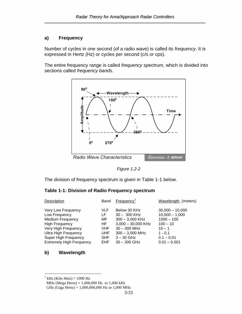
1.2.3 Radio Wave Characteristics Since electromagnetic radiation is a wave phenomenon, it has certain characteristics associated with waves. The oscillations of an electromagnetic wave occur back and forth across the direction of the wave's propagation. Thus, an electromagnetic wave completes ONE cycle after it has made TWO alterations, one in positive direction and one in negative direction, as illustrated below in figure 1.2-2
RRaaddaarr TThheeoorryy ffoorr AArreeaa//AApppprrooaacchh RRaaddaarr CCoonnttrroolllleerrss
3/33
a) Frequency Number of cycles in one second (of a radio wave) is called its frequency. It is expressed in Hertz (Hz) or cycles per second (c/s or cps). The entire frequency range is called frequency spectrum, which is divided into sections called frequency bands.
Figure 1.2-2
The division of frequency spectrum is given in Table 1-1 below. Table 1-1: Division of Radio Frequency spectrum Description Band Frequency
1 Wavelength (meters)
Very Low Frequency VLF Below 30 KHz 30,000 – 10,000 Low Frequency LF 30 – 300 KHz 10,000 – 1,000 Medium Frequency MF 300 – 3,000 KHz 1000 – 100 High Frequency HF 3,000 – 30,000 KHz 100 – 10 Very High Frequency VHF 30 – 300 MHz 10 – 1 Ultra High Frequency UHF 300 – 3,000 MHz 1 - 0.1 Super High Frequency SHF 3 – 30 GHz 0.1 – 0.01 Extremely High Frequency EHF 30 – 300 GHz 0.01 – 0.001
b) Wavelength
1 kHz (Kilo Hetz) = 1000 Hz
MHz (Mega Hertz) = 1,000,000 Hz or 1,000 kHz
GHz (Giga Hertz) = 1,000,000,000 Hz or 1,000 MHz

RRaaddaarr TThheeoorryy ffoorr AArreeaa//AApppprrooaacchh RRaaddaarr CCoonnttrroolllleerrss
4/33
The distance that a radio wave travels in the time of one cycle is called its wavelength. It is expressed in meters. c) Amplitude The size of the wave form, measured from the mean to the crest or trough is known as amplitude of the signal. d) Velocity The rate of change of position per unit of time is called velocity. It is the product of the number of cycles per second (Hertz) and the wavelength. Radio waves travel at the speed as of the light i,e 186,000 miles/sec or 300,000 km/sec or 162,000 NM/sec. 1.2.4 Velocity, Time and Distance relationship These four radio wave characteristics, as given above, are connected one with the other and obey the Law of Motion, which states: Distance = Velocity x Time
Since f
1T , therefore, the above formula may be expressed as :
Wavelength (in meters) = Velocity (in m per sec) x Time for One cycle (seconds)
f
1cx=ly symbolical 1
f
c= d simplifiewhich 2
As velocity is a constant it therefore follows that given the wavelength, the frequency can be calculated or conversely, given the frequency, the wavelength can be calculated, since if:
f
c = 3
c = f then 4
Where „c‟ is the velocity of the light (or radio waves), „f‟ is frequency in Hz (or cycles per second) and „‟ is the wavelength in meters.
RRaaddaarr TThheeoorryy ffoorr AArreeaa//AApppprrooaacchh RRaaddaarr CCoonnttrroolllleerrss
5/33
1.2.5 Examples a) Frequency 6250 KHz, find wavelength:
f
c = 5
6250
300000 = 6
meters 48 = 7
b) Frequency 118.1 MHz, find wavelength:
f
c = 8
m 2.54 = 118.1
300 = 9
In these two examples it is convenient to use a modified constant according to whether the frequency is expressed in KHz or MHz. c) Wavelength 1500 M, find frequency:
C = F 10
1500
103x = f
8
11
f = 200,000 Hz or 200 KHz d) Wavelength 10 CM (a common radar wavelength), find frequency:
c = f 12
0.1
103x = f
8
13
1
103x = f
9
14
f = 3,000 MHz

RRaaddaarr TThheeoorryy ffoorr AArreeaa//AApppprrooaacchh RRaaddaarr CCoonnttrroolllleerrss
6/33
Figure 1.2-3: Radar frequencies and microwaves in frequency spectrum
RRaaddaarr TThheeoorryy ffoorr AArreeaa//AApppprrooaacchh RRaaddaarr CCoonnttrroolllleerrss
7/33
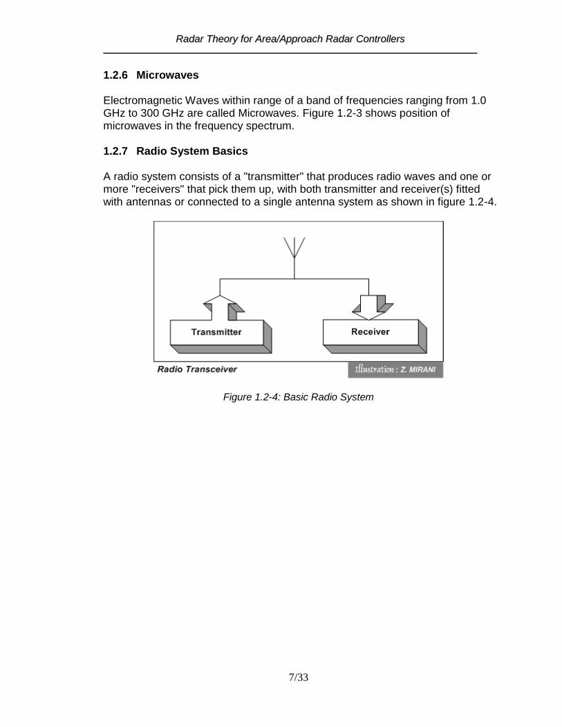
1.2.6 Microwaves Electromagnetic Waves within range of a band of frequencies ranging from 1.0 GHz to 300 GHz are called Microwaves. Figure 1.2-3 shows position of microwaves in the frequency spectrum. 1.2.7 Radio System Basics A radio system consists of a "transmitter" that produces radio waves and one or more "receivers" that pick them up, with both transmitter and receiver(s) fitted with antennas or connected to a single antenna system as shown in figure 1.2-4.
Figure 1.2-4: Basic Radio System

RRaaddaarr TThheeoorryy ffoorr AArreeaa//AApppprrooaacchh RRaaddaarr CCoonnttrroolllleerrss
8/33
1.3 Radar 1.3.1 Principle of Operation Radar is a method whereby radio waves are transmitted into the air in a specific direction and are received when they are reflected by an object in the path of the beam. RANGE in RADAR is determined by measuring the time, radio wave takes, from radiation to return of its echo; whereas DIRECTION is determined from the position of antenna at the time of reception of signal. 1.3.2 Range determination in Radar The distance of an object from a Radar station is called “slant range” or simply “range”. Range in Radar is determined by an expression given below.
Range = 2
x t c
Where „c‟ is speed of radio waves and „t‟ is the time elapsed from transmission of radio waves to the reception of echo. Example If total time elapsed, from transmission of radio waves to the reception of echo, is 1000 microseconds. Velocity of radio waves is constant and given as 161,800 NM per second. Then
Range = 2
µ 1000 x 161,800
Range = 80.9 or 81 NM Time elapsed from transmission to reception of radio waves to travel for one nautical mile or simply range time for one nautical mile is Time = 2 x 1 NM / 161,800 NM per sec = 12.36 microseconds Therefore, range of a target can also be determined by dividing the time elapsed from transmission of radio waves to the reception of echo by range time of one NM. Range = 1000 microseconds / 12.36 microseconds
= 80.9 NM or 81 NM

RRaaddaarr TThheeoorryy ffoorr AArreeaa//AApppprrooaacchh RRaaddaarr CCoonnttrroolllleerrss
9/33
1.3.3 Types of Radar
There are various techniques used in radar systems to detect the objects by using radio waves. 1.3.3.1 CW Radar Continuous wave radar (CW radar) continually transmits energy in the direction of the target and receives back reflection of the continuous wave. A continuous wave radar can provide velocity information by comparing the differences in the transmitted and received waves and making use of the Doppler effect. 1.3.3.2 FM Radar CW radar cannot determine target range because it lacks the timing mark necessary to allow the system to time accurately the transmit and receive cycle and convert this into range. To overcome this deficiency CW radars make use of FM, hence, called FM CW Radar. 1.3.3.3 Doppler Radar Doppler radar is basically CW radar that allows the speed of a target to be measured using the Doppler effect. When a signal from a radar is scattered by a target, its frequency is changed in proportion to the speed of the target. By measuring this change in frequency, a doppler radar is able to infer the target's speed. Doppler RADAR can detect the location and intensity of storms (reflectivity), the speed and direction of wind (velocity), and the total accumulation of rainfall (storm total). 1.3.3.4 Pulse Radar A pulse radar transmits pulses of short duration of RF energy. The time delay of reflections (or echo) of these pulses is measured and converted into distance to that target. 1.4 Basic Pulse Radar System The major components of a pulse radar are the transmitter, the antenna system, the receiver and the display as shown in the figure 1.4-1. Pulses of RF energy are transmitted in a particular direction by radar transmitter. A portion of this energy is reflected by the objects, which comes into the path of the radar radiation, and collected by the radar receiver. The range information is calculated by using delay time of the received signal. This range information is

RRaaddaarr TThheeoorryy ffoorr AArreeaa//AApppprrooaacchh RRaaddaarr CCoonnttrroolllleerrss
10/33
displayed on the Radar Scope along with bearing of the object, which is determined from direction of antenna at the time of reception of echo. 1.5 Types of ATC Radar 1.5.1 Primary Radar It provides “Range and Bearing” information to the Air Traffic Control Center. It does not need cooperation of the aircraft for it depends upon reflection of the radio waves transmitted by the system itself. 1.5.2 Secondary Radar It provides “identification and altitude” information to ground ATC. It works with cooperation of the aircraft. The information produced by the Secondary Radar is therefore function of both ground equipment and airborne equipment.
Figure 1.4-1: Basic radar system
RRaaddaarr TThheeoorryy ffoorr AArreeaa//AApppprrooaacchh RRaaddaarr CCoonnttrroolllleerrss
11/33
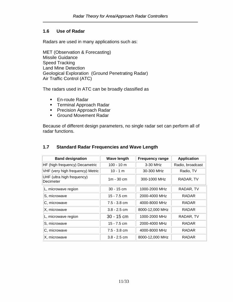
1.6 Use of Radar Radars are used in many applications such as: MET (Observation & Forecasting) Missile Guidance Speed Tracking Land Mine Detection Geological Exploration (Ground Penetrating Radar) Air Traffic Control (ATC) The radars used in ATC can be broadly classified as
En-route Radar Terminal Approach Radar Precision Approach Radar Ground Movement Radar
Because of different design parameters, no single radar set can perform all of radar functions. 1.7 Standard Radar Frequencies and Wave Length
Band designation Wave length Frequency range Application
HF (high frequency) Decametric 100 - 10 m 3-30 MHz Radio, broadcast
VHF (very high frequency) Metric 10 - 1 m 30-300 MHz Radio, TV
UHF (ultra high frequency) Decimeter
1m - 30 cm 300-1000 MHz RADAR, TV
L, microwave region 30 - 15 cm 1000-2000 MHz RADAR, TV
S, microwave 15 - 7.5 cm 2000-4000 MHz RADAR
C, microwave 7.5 - 3.8 cm 4000-8000 MHz RADAR
X, microwave 3.8 - 2.5 cm 8000-12,000 MHz RADAR
L, microwave region 30 - 15 cm 1000-2000 MHz RADAR, TV
S, microwave 15 - 7.5 cm 2000-4000 MHz RADAR
C, microwave 7.5 - 3.8 cm 4000-8000 MHz RADAR
X, microwave 3.8 - 2.5 cm 8000-12,000 MHz RADAR

RRaaddaarr TThheeoorryy ffoorr AArreeaa//AApppprrooaacchh RRaaddaarr CCoonnttrroolllleerrss
12/33
1.8 Primary Radar 1.8.1 Construction Practical Primary Radar system is composed of following essential components.
a) Timer or Synchronizer b) Modulator c) Transmitter d) Antenna e) Duplexer or TR switch f) Receiver and g) Indicator or Radar Scope
Figure 1.8-1: Block diagram of Primary Radar System
RRaaddaarr TThheeoorryy ffoorr AArreeaa//AApppprrooaacchh RRaaddaarr CCoonnttrroolllleerrss
13/33
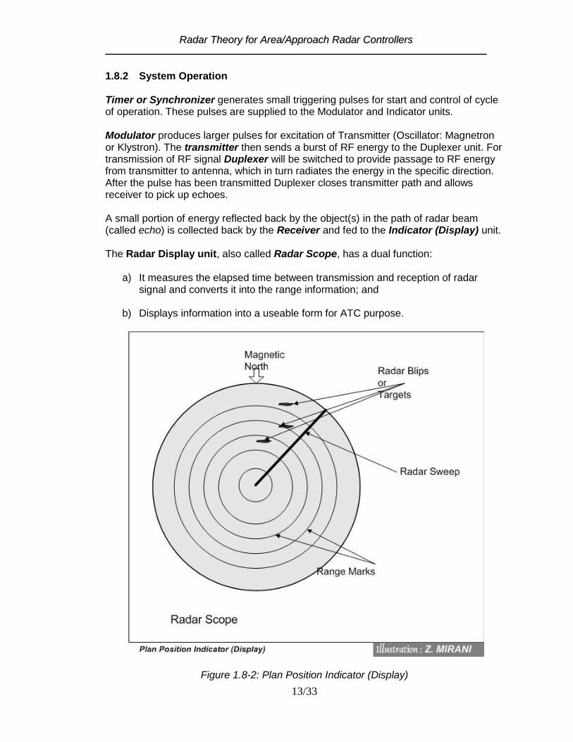
1.8.2 System Operation Timer or Synchronizer generates small triggering pulses for start and control of cycle of operation. These pulses are supplied to the Modulator and Indicator units. Modulator produces larger pulses for excitation of Transmitter (Oscillator: Magnetron or Klystron). The transmitter then sends a burst of RF energy to the Duplexer unit. For transmission of RF signal Duplexer will be switched to provide passage to RF energy from transmitter to antenna, which in turn radiates the energy in the specific direction. After the pulse has been transmitted Duplexer closes transmitter path and allows receiver to pick up echoes. A small portion of energy reflected back by the object(s) in the path of radar beam (called echo) is collected back by the Receiver and fed to the Indicator (Display) unit. The Radar Display unit, also called Radar Scope, has a dual function:
a) It measures the elapsed time between transmission and reception of radar signal and converts it into the range information; and
b) Displays information into a useable form for ATC purpose.
Figure 1.8-2: Plan Position Indicator (Display)

RRaaddaarr TThheeoorryy ffoorr AArreeaa//AApppprrooaacchh RRaaddaarr CCoonnttrroolllleerrss
14/33
1.8.3 Primary Radar Indicator
Information made available by the primary radar may be presented to an operator in a number of ways. The presentation on an indicator showing all targets within range that are detected as the antenna rotates is called a Plan Position Indicator (PPI). Cathode ray Tube (CRT) is found suitable to be used as PPI to display radar information as close as the real situation. It makes interpretation of radar easier than other types of indicator. In PPI the scanning (sweep) starts from the center of the screen and moves outward. The distance between the center and the circumference of the screen represents the maximum range at which the radar is required to provide coverage. When the spot reaches the edge of the screen, it returns to the center extremely fast to start the next scan. This action is known as „Flyback‟. To display the range of an object, the spot starts its sweep as the pulse is transmitted (by the antenna) and a „blip‟ is shown at the time when „echo‟ of the transmitted signal is received. The sweep is arranged to rotate in steps with the rotation of the radar antenna, to show the bearing of the objects appearing in the path of the radar beam. Radar Echo is the signal received (reflected) from an object that appears in the path of the radar beam. Radar Blip is a visual indication on a display of a signal reflected from an object. Range Marks appears as concentric rings with their center at the beginning of the time base. Each range mark corresponds to a specified distance from the center of the scope say 5, 10, 15, 20, 25 and so on. The range mark generator produces a series of regularly spaced pulses at intervals corresponding to the range marks. Video map is presentation of useful information (such as airways, reporting points, boundaries etc) on a radar scope.
1.8.4 Evaluation of Radar Echoes to Identify Targets
Targets are distinguished with respect to the following factors:
Target Velocity Target Intensity and Fluctuations Behavior Relative To Other Targets
RRaaddaarr TThheeoorryy ffoorr AArreeaa//AApppprrooaacchh RRaaddaarr CCoonnttrroolllleerrss
15/33
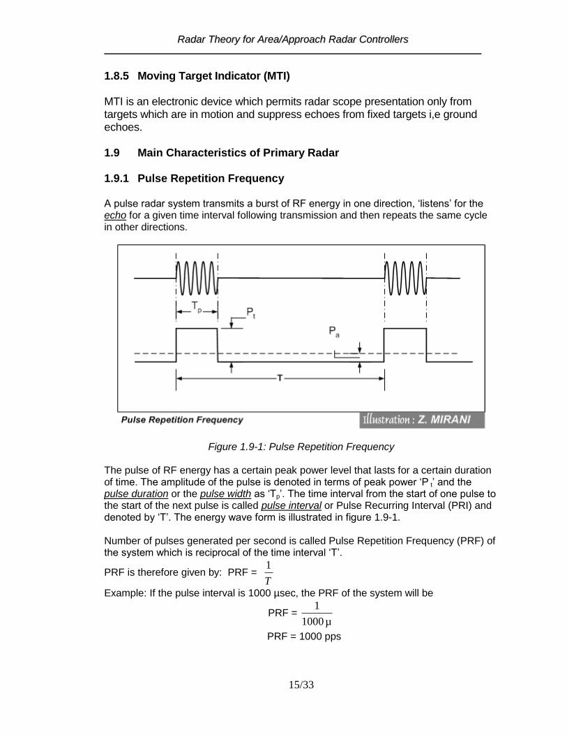
1.8.5 Moving Target Indicator (MTI) MTI is an electronic device which permits radar scope presentation only from targets which are in motion and suppress echoes from fixed targets i,e ground echoes. 1.9 Main Characteristics of Primary Radar 1.9.1 Pulse Repetition Frequency A pulse radar system transmits a burst of RF energy in one direction, „listens‟ for the echo for a given time interval following transmission and then repeats the same cycle in other directions.
Figure 1.9-1: Pulse Repetition Frequency The pulse of RF energy has a certain peak power level that lasts for a certain duration of time. The amplitude of the pulse is denoted in terms of peak power „P t‟ and the pulse duration or the pulse width as „Tp‟. The time interval from the start of one pulse to the start of the next pulse is called pulse interval or Pulse Recurring Interval (PRI) and denoted by „T‟. The energy wave form is illustrated in figure 1.9-1. Number of pulses generated per second is called Pulse Repetition Frequency (PRF) of the system which is reciprocal of the time interval „T‟.
PRF is therefore given by: PRF = T
1
Example: If the pulse interval is 1000 µsec, the PRF of the system will be
PRF = µ 1000
1
PRF = 1000 pps

RRaaddaarr TThheeoorryy ffoorr AArreeaa//AApppprrooaacchh RRaaddaarr CCoonnttrroolllleerrss
16/33
When pulses are transmitted at a high rate, the receiver listening time between pulses for return echoes is reduced as well as the corresponding distance to which the energy can travel and return. The maximum working range required of a radar is specified when deciding the function of the radar. Relationship between maximum (theoretical) range of a radar and its PRF is given by:
meters 2xPRF
103x = range ltheoritica .
8
Max 15
The above relationship indicates that any increase in the PRF will reduce the maximum
range, and a lower PRF will increase it.
1.9.2 Strikes per scan When an echo returns from a target, the CRT spot brightens at the appropriate range and bearing. One "bright up", however, is insufficient to be seen by the human eye. As the beam sweeps through the target, more pulses "strike" it and return, causing multiple bright up of the spot. This makes the echo visible to the eye as a "blip". The number of strikes can be calculated by the formula given below.
RPMx6
PRFBeamwidthx = strikesof No. 16
The number of strikes per scan is always quoted as a whole number, i.e.: if, for instance,
a result of 11.8 is yielded by the above formula it would be assumed as 12.
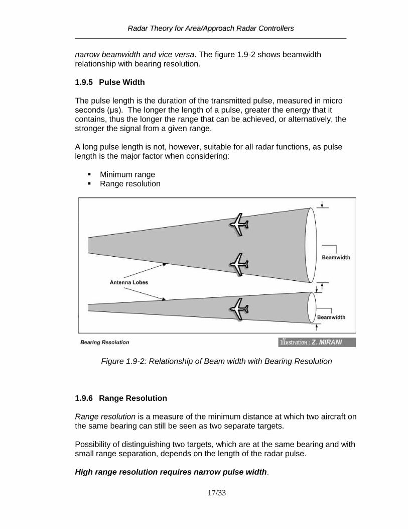
1.9.3 Scan Rate Scan Rate is usually quoted in revolutions per minute (RPM). The scan rate controls the rate of renewal of displayed information - i.e higher the scan more rapid will be the rate of renewal of information. A rapid rate of renewal of information is particularly required for the short-range approach functions, and is of less importance for the longer range area and TMA functions. It can be stated, in general, that the longer the working range, the lower the scan rate acceptable. 1.9.4 Beam Width The beamwidth controls the Bearing Resolution of a radar, which is measured as the minimum separation distance at which two aircraft at the same range can be seen as two separate targets. High azimuth or bearing resolution requires a
RRaaddaarr TThheeoorryy ffoorr AArreeaa//AApppprrooaacchh RRaaddaarr CCoonnttrroolllleerrss
17/33
narrow beamwidth and vice versa. The figure 1.9-2 shows beamwidth relationship with bearing resolution. 1.9.5 Pulse Width The pulse length is the duration of the transmitted pulse, measured in micro seconds (μs). The longer the length of a pulse, greater the energy that it contains, thus the longer the range that can be achieved, or alternatively, the stronger the signal from a given range. A long pulse length is not, however, suitable for all radar functions, as pulse length is the major factor when considering:
Minimum range Range resolution
Figure 1.9-2: Relationship of Beam width with Bearing Resolution 1.9.6 Range Resolution Range resolution is a measure of the minimum distance at which two aircraft on the same bearing can still be seen as two separate targets. Possibility of distinguishing two targets, which are at the same bearing and with small range separation, depends on the length of the radar pulse.
High range resolution requires narrow pulse width.

RRaaddaarr TThheeoorryy ffoorr AArreeaa//AApppprrooaacchh RRaaddaarr CCoonnttrroolllleerrss
18/33
1.9.7 Sensitivity Time Control (STC) The receiver echo pulse power is strongly dependent upon the distance to the target. In order to have same brightness on the PPI for echoes at all distances, echoes at long distances must be amplified more than echoes at short distances. The receiver of radar, therefore, has Sensitivity Time Control (STC), which is distance dependent amplification. 1.9.8 Blind Speed Cancellation of echoes from fixed targets is made on the basis of comparison of echoes on pulse to pulse basis. Only targets whose distance to the radar is changed are separated this way. In cases where radar cannot measure speed of a target, will suppress it assuming as a fixed target. Such type of problem with pulse to pulse MTI is called Blind Speed. Targets with specific speed in relation to PRF will be suppressed. This problem is solved through varying PRF called staggering. 1.10 Radar Equation Other important operating characteristics of radar are its transmitted power and wavelength (or frequency). The strength of an echo from a target varies directly with the transmitted power. The wavelength is important in the detection of certain types of targets such as those composed of many small particles. When the particles are small relative to the wavelength, their detectability is greatly reduced. Thus drizzle is detectable by short wavelength (0.86 cm.) radars but is not generally detectable by longer (23 cm.) wavelength radars. Maximum range in radar depends on various factors and is given by
Rmax = 42 Pr(min)16
ArPtG meters
Where „R‟ is maximum radar range, Pt is transmitted power, G is power gain of the antenna, is echoing area of the target, Ar is absorbing area of the antenna and Pr is
received power. It can be observed from the above equation that doubling the transmitted power will result in increase of 19% range and in order to double the range transmitter power is required 16 fold increase.
Substituting value of Ar from equation
4
2GAr , we obtain
Rmax = 43
22
Pr(min)64
PtG meters

RRaaddaarr TThheeoorryy ffoorr AArreeaa//AApppprrooaacchh RRaaddaarr CCoonnttrroolllleerrss
19/33
It can be noticed that wavelength has been introduced into the equation. Increase in range can easily be achieved by increasing antenna gain for a given wavelength by applying this new relationship instead of the transmitted power.
1.11 Factors Affecting Radar Performance
1. The power of transmitter 2. The frequency of the transmitter 3. Noise generated within the receiver 4. The sensitivity of the receiver External 5. The time interval between pulses and pulse width. 6. The shape and dimensions of the radar beam 7. The size and shape of the object and the material of which it is made
8. Radio Frequency Interference (caused by radiation of spurious and/or undesired radio frequency signals from other non-associated electronic equipment, such as navigational aids, data processing computers, voice communication systems, other radars, and from more common sources, such as ignition and electric motor control systems)
9. Noise caused by natural phenomenon (eg. by Thundering, Lightening) 10. Signals reflected by natural phenomenon (eg. Precipitation: snow, rain, mist,
clouds with high humidity) 11. Distant ground returns and "Angels” (eg. Returns from Insects, Birds, different
local developments at terrain, sea and ocean ) 12. The curvature of the earth 13. Returns from the side and back lobes
RRaaddaarr TThheeoorryy ffoorr AArreeaa//AApppprrooaacchh RRaaddaarr CCoonnttrroolllleerrss
20/33
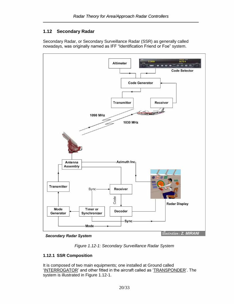
1.12 Secondary Radar Secondary Radar, or Secondary Surveillance Radar (SSR) as generally called nowadays, was originally named as IFF “Identification Friend or Foe” system.
Figure 1.12-1: Secondary Surveillance Radar System 1.12.1 SSR Composition It is composed of two main equipments; one installed at Ground called „INTERROGATOR‟ and other fitted in the aircraft called as „TRANSPONDER‟. The system is illustrated in Figure 1.12-1.

RRaaddaarr TThheeoorryy ffoorr AArreeaa//AApppprrooaacchh RRaaddaarr CCoonnttrroolllleerrss
21/33
1.12.3 Principle Of Operation The interrogator transmits a series of pulses with specific time intervals, as standardized by ICAO, over a directional antenna. The pulses are received by the Transponder, which after fixed time delay responds with a series of pulses which are coded with information about identity and altitude of the aircraft. 1.12.4 Operating Frequencies 1030 MHz is used as the carrier frequency of the interrogation and 1090 MHz is used as the carrier frequency of the reply transmission. 1.12.5 Interrogation The interrogation consists of two transmitted pulses designated as P1 and P3. A control pulse P2 is transmitted following the first interrogation pulse P1. The interval between P1 and P3 determines the mode of interrogation and shall be as follows: Mode A 8 ±0.2 microseconds Mode C 21 ±0.2 microseconds. The interval between P1 and P2 shall be 2.0 microseconds. The duration of pulses P1, P2 and P3 shall be 0.8 plus or minus 0.1microsecond. 1.12.6 Modes of Transmission Six different combinations of interrogation pulses are standardized, each having a specific meaning. These combinations are termed as MODES in SSR system. The Figure 1.12-2 shows the position of P1, P2 and P3 pulses for each mode of interrogation. Mode A: to elicit transponder replies for identity and surveillance. Mode C: to elicit transponder replies for automatic pressure-altitude transmission and
surveillance. Inter-mode: a) Mode A/C/S all-cal l: to elicit replies for surveillance of Mode A/C transponders and
for the acquisition of Mode S transponder. b) Mode A/C-only all-call: to elicit replies for surveillance of Mode A/C transponders;
Mode S transponder does not reply. Mode S: a) Mode S-only all-call: to elicit replies for acquisition of Mode S transponders. b) Broadcast: to transmit information to all Mode S transponders. No replies are
elicited.

RRaaddaarr TThheeoorryy ffoorr AArreeaa//AApppprrooaacchh RRaaddaarr CCoonnttrroolllleerrss
22/33
c) Selective: for surveillance of, and communication with, individual Mode S
transponders. For each interrogation, a reply is elicited only from the transponder uniquely addressed by the interrogation.
Figure 1.12-2: Modes of Interrogation in SSR 1.12.7 Reply (from Transponder) In reply to interrogation in Mode-A and Mode-B information of identity, which is set by the pilot, is sent to the ground interrogator. On an interrogation in Mode-C, the coded information from altimeter (pressure-altitude) is transmitted to the ground station without involvement of an action of the pilot. The reply function employ a signal comprising two „framing pulses‟ spaced 20.3 microseconds as the most elementary code. Transponder reply format is shown in Figure 1.12-3. The reply of transponder contains two types of pulses: (a) Frame pulses F1 and F2 (b) Combination of Information pulses

RRaaddaarr TThheeoorryy ffoorr AArreeaa//AApppprrooaacchh RRaaddaarr CCoonnttrroolllleerrss
23/33
Information pulses are spaced in increments of 1.45 microseconds from the first framing pulse. The designation and position of these information pulses is illustrated in the following figure. Note The position of the “X” pulse is specified only as a technical standard to safeguard possible future use.
Figure 1.12-3: Transponder Reply Format 1.12.8 Code nomenclature The combination of A, B, C and D pulses, as shown in figure above, allows 4096 codes. The range of codes, in ABCD format, is from 0000 to 7777. Note: The digits 8 and 9 are not used in the code system because each „ABCD” pulse group contains only three pulses which allow transmission of only three binary digits (bits) in each group. There are maximum eight (decimal) counts possible with three (binary) digits or bits which are represented from 0 through 7 (in decimal system). Decoding Reply Pulses In Mode-A and Mode-B information of identity, which is set by the pilot, is sent to the ground interrogator. On an interrogation in Mode-C, the coded information from altimeter (pressure-altitude) is transmitted to the ground station without involvement of an action of the pilot. Reply to mode A and B interrogation The sequence of the pulses (binary digits or bits) of the reply code is given below in accordance with their weight. The A4 pulse of group A is the most significant bit and D1 is the least significant bit. A4 A2 A1 B4 B2 B1 C4 C2 C1 D4 D2 D1 Taking example of one group of pulses, we notice that there may be seven possible combinations of the three pulses as given below. The three pulses, therefore, can count as follows:

RRaaddaarr TThheeoorryy ffoorr AArreeaa//AApppprrooaacchh RRaaddaarr CCoonnttrroolllleerrss
24/33
A4 A2 A1 Count (in Decimal) 0 0 0 0 0 0 1 1 0 1 0 2 0 1 1 3 1 0 0 4 1 0 1 5 1 1 0 6 1 1 1 7 0 and 1 in a pulse position denotes absence or presence of a pulse, respectively. Example: If the reply pulses A4 A2A1 B4 B2 B1 C4C2C1 D4D2D1 received by SSR ground component are 110010100101 (respectively) , the SSR code sent by the aircraft is 6 2 4 5. Reserved Codes The following Mode A codes are reserved for special purposes: Code 7700: to provide recognition of an aircraft in an emergency. Code 7600: to provide recognition of an aircraft with radio communication failure. Code 7500: to provide recognition of an aircraft which is being subjected to unlawful interference. Mode A code 2000 is reserved to provide recognition of an aircraft which has not received any instructions from air traffic control units to operate the transponder. Mode A code 0000 should be reserved for allocation subject to regional agreement, as a general purpose code. Replies to mode C interrogation: In Mode C automatic transmission of pressure-altitude is made by the transponder. Pressure altitude is reported in 100 feet increments. The altitude information (pulses) are automatically generated through analog-to-digital converter connected to a pressure altitude data source in the aircraft.

RRaaddaarr TThheeoorryy ffoorr AArreeaa//AApppprrooaacchh RRaaddaarr CCoonnttrroolllleerrss
25/33
1.13 SSR Mode – S Mode S is a new type of secondary radar which is also based on the use of a transponder on board the aircraft, responding to interrogations from ground station (called interrogator). The dialogue between a conventional secondary radar and a conventional transponder uses two modes, A and C. Mode S (selective) is an improvement in conventional secondary radar. It is compatible with normal SSR, operating at the same frequencies (1030/1090 MHz). Its selectivity is based on identification of the aircraft by it‟s 24-bit address, which acts as it‟s technical telecommunications address. In addition, Mode S can be used to exchange longer and more varied data. To do this, Mode S transmissions between the station and the transponder use highly sophisticated 56 or 112 bit formats called frames that fall into 3 main categories:
56-bit surveillance formats 112 bit communication formats with a 56-bit data field, which are in fact
extended surveillance formats (Uplink COMM-A's and Downlink COMM-B's) 112 bits communication formats with an 80-bit data (uplink COMM-D's downlink
COMM-D's)
Figure 1.13-1: SSR Mode S – Specific Data Link Configuration

RRaaddaarr TThheeoorryy ffoorr AArreeaa//AApppprrooaacchh RRaaddaarr CCoonnttrroolllleerrss
26/33
1.13.1 Mode S data link
There are two types of Mode S data link, one called "specific" and the other one "interoperable".
To simplify, we can say that in “specific” type of operation, the ground station and the transponder know the type of information contained in the data fields; whereas in "interoperable" both ground and airborne stations can exchange any type of data they want.
The specific data link is more closely linked to the Mode S (Surveillance) system. This, in particular, is used for highly optimized "aircraft data collection" using the COMM-B frames. It works the following way.
The transponder contains series of 256 buffers of 56 bits each, in which information concerning the flight and aircraft status are stored and permanently refreshed. Each buffer, identified by an order number, contains data of a precise nature formatted according to a predetermined code. The transponder is, thus, considered as a multiple mailbox in which the aircraft system places its flight data (without knowing whether or not anyone will pick them up) whereas on the other side, the ground station reads the data completely asynchronously.
Mode S "basic" selective surveillance only requires the use of Mode S ground sensors and airborne Mode S transponders, as shown in figure 1.13-1
Figure 1.13-2: Mode S data link sub-network
RRaaddaarr TThheeoorryy ffoorr AArreeaa//AApppprrooaacchh RRaaddaarr CCoonnttrroolllleerrss
27/33
The interoperable data link allows ground-to-air data exchange using Mode S as a packet switching data transmission network. The messages (in the form of packets) sent from the station to the transponder (or vice-versa), are cut into pieces to separate the data and address fields. The extracted data fields are,then, reconstituted and routed to the desired destination (addressee).
Interoperable services, therefore, need supplementary equipment on both sides, called respectively Ground and Airborne Data Link Processors. Figure 1.13-3 shows Mode S data link sub-network.
The interoperable services allow the integration of Mode S sub-networks in the Aeronautical Telecommunication Network (A.T.N.) – future global communication service, which allows ground, air-ground and avionics data sub-networks to inter-operate for the specified aeronautical applications.
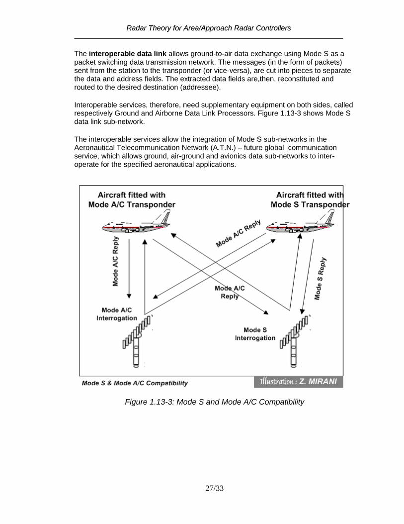
Figure 1.13-3: Mode S and Mode A/C Compatibility
RRaaddaarr TThheeoorryy ffoorr AArreeaa//AApppprrooaacchh RRaaddaarr CCoonnttrroolllleerrss
28/33
1.14 Comparison of Primary and Secondary Radars
PSR SSR
1 The response is independent of
target cooperation 2 Power requirement : High 3 Response depends upon size and
type (material) of target 4 Position of target is closest to its
actual position (better bearing accuracy as compared to SSR)
5 Only Bearing and Range of target
is displayed 6 Weather and Stationary objects
(mountains, high rise buildings etc can be seen)
1 Cooperation of the target (Pilot) is
required for response 2 Power requirement : Less 3 Response is independent of target
size and material 4 Bearing accuracy is not as good
as of PSR 5 Identification and altitude
information of target is provided 6 Display of weather and stationary
not provided
1.15 Radar Display System Radar Display System performs the following main functions:
1. Reception of Raw Videos and Synthetic (Processed) data from Radar heads 2. Radar Track processing 3. Radar and Flight Plan data processing 4. Data Distribution to various peripherals 5. Display/Representation of information
A typical architecture of a modern ATC system is given below in Fig: 3-7 1.15.1 General System Configuration Radar Display system comprises of
1. Radar Tracking Processor 2. Radar Data and Flight Plan Processor 3. Interfacing elements 4. Signal and Data Distribution Network 5. Display (Visualization) Unit(s)

RRaaddaarr TThheeoorryy ffoorr AArreeaa//AApppprrooaacchh RRaaddaarr CCoonnttrroolllleerrss
29/33
Figure 1.15-1: Components of a General Radar Display System
1.15.2 Functions of RDS Components Radar Tracking Processor performs the following main functions:
Associates the plots supplied by the radar which corresponds to the same aircraft
Calculate the flight path of the aircraft
Construct a definitive „track‟ defining the position, direction and speed of the aircraft
A radar „track‟ is displayed as the present and past positions of the aircraft. Secondary radar track also indicates aircraft identification code or call sign, flight level, speed and the type of the aircraft.

RRaaddaarr TThheeoorryy ffoorr AArreeaa//AApppprrooaacchh RRaaddaarr CCoonnttrroolllleerrss
30/33
Radar Data and Flight Plan Processor performs
Mono or multi radar data processing
Flight plan processing In multi radar processing, it is possible that a same target is detected by several radars. Multi radar processor in that case ensures display of one track per target (aircraft). Flight plan processing involves
The use of repetitive flight plans (data base)
Strip printing
Input and modification of flight plan on visual display unit (radar scope)
Automatic allocation of SSR codes
Correlation of radar track data with flight plan data Signal and Data Distribution Network Radar Video Signals & Data and Flight Plan data are distributed through a network comprising standard communication links. Manufacturers of ATC systems provide customized data and signal distribution units in may cases though standard data and signal distribution equipments can also be used. Display/Visualization Unit (or Radar scope as generally called), mainly, comprises
A processing unit
Input device(s) such as Keyboard, Track ball etc
A display screen (monitor) A display processing unit generates radar and synthetic images on a Plan Position Indicator. To perform this function it
Stores digital data received from Radar & Flight Plan data processor and data from various peripherals
Executes the software program to process the received data
Groups information to be displayed
Converts digital data into analog signals
1.15.3 System Inputs received from radar head
1. Video Signals (Raw Video, as some times called) including
Processed Video
Normal Video
Weather map 2. Azimuth increment (typical value 4096 per antenna revolution) 3. North Signal 4. Synthetic data (Radar Tracks and Plots)
RRaaddaarr TThheeoorryy ffoorr AArreeaa//AApppprrooaacchh RRaaddaarr CCoonnttrroolllleerrss
31/33
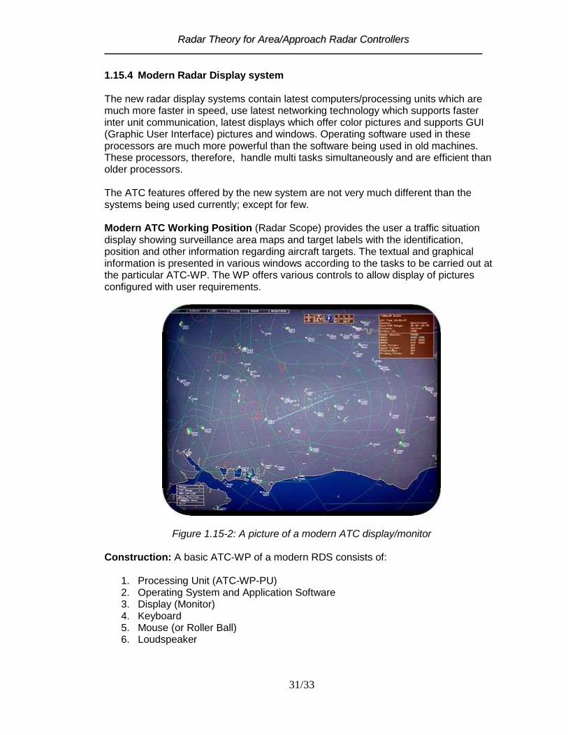
1.15.4 Modern Radar Display system The new radar display systems contain latest computers/processing units which are much more faster in speed, use latest networking technology which supports faster inter unit communication, latest displays which offer color pictures and supports GUI (Graphic User Interface) pictures and windows. Operating software used in these processors are much more powerful than the software being used in old machines. These processors, therefore, handle multi tasks simultaneously and are efficient than older processors. The ATC features offered by the new system are not very much different than the systems being used currently; except for few. Modern ATC Working Position (Radar Scope) provides the user a traffic situation display showing surveillance area maps and target labels with the identification, position and other information regarding aircraft targets. The textual and graphical information is presented in various windows according to the tasks to be carried out at the particular ATC-WP. The WP offers various controls to allow display of pictures configured with user requirements.
Figure 1.15-2: A picture of a modern ATC display/monitor Construction: A basic ATC-WP of a modern RDS consists of:
1. Processing Unit (ATC-WP-PU) 2. Operating System and Application Software 3. Display (Monitor) 4. Keyboard 5. Mouse (or Roller Ball) 6. Loudspeaker

RRaaddaarr TThheeoorryy ffoorr AArreeaa//AApppprrooaacchh RRaaddaarr CCoonnttrroolllleerrss
32/33
The loud speaker is also used in some systems to provide an audible alarm, which is triggered by aircraft emergency (e.g 7700, 7600, 7500), Air-route Deviation or system alarms. Windows and Icons Windows are used for input of alphanumeric data and for display of important information. Some windows can be minimized to icons when not in use. Types of windows used are:
1. Input windows 2. Pop up windows (system alarm, Special Code Alert and alarm/alert
acknowledgement) 3. Operator messages 4. Pop up window to notify the input of non valid values and incorrect input action 5. Picture In Picture (PIP) window showing selected portion of the total display
area 6. Tabular Data window displays system status information 7. Target Information
Aircraft labels and symbols:
Color of the normal label can be one and the alarm color can be other (red fro example)
There is selection of Font size and Type
The label may consist of four lines; L1: Call sign or SSR Code, L2: Flight level or altitude and Aircraft Type‟ L3: Ground Speed and L4: Short Note (when full label selected)
Display Colors: Separate colors are available for various elements of display. Figure 1.15-2 shows a modern ATC display/monitor picture that is very much similar to a computer monitor.

RRaaddaarr TThheeoorryy ffoorr AArreeaa//AApppprrooaacchh RRaaddaarr CCoonnttrroolllleerrss
33/33
1.16 Siting of radars Effect of Ground The presence of the Earth's surface is a factor of great importance in radar aerial design and in the siting of radar because of its influence on vertical coverage. Waves are reflected which are either in phase or out of phase with direct radiation and by either combining with or canceling direct radiation causes lobes in the required direction. Remember in shorter wavelengths the signals combine better giving a much better low coverage than the longer wavelengths. Factors in siting The following factors need consideration when the site for a radar head is being planned: a) The distance between the displays and the head- limitations of remote linking. b) Elevation of the site - High ground - screening aspect of adjoining buildings, etc. c) Height of the aerial above ground level - ground reflections - lobes. d) Ground itself - flat - sloping - grass - concrete - what effect will type of surface have
on pulses which will be reflected. e) Aerial proximity to runways, etc. - obstruction - SRA for as many runways as possible. f) Domestic matter - access roads - power supplies, etc. Vertical coverage obtained is directly affected by (b), (c) and (d) above. It may also be varied in the equipment by changes in Aerial tilt - Frequency, etc. Remote Display Sites The radar data (tracks, plots), video (normal, processed, weather) and other signals (such as north signal, increment) may be transmitted to a remote display site by a) Telephone Lines b) Co-axial Cables c) Radio Microwave Links and Repeaters d) Satellite Links


![GROUND PENETRATING RADAR · Basic Theory Applications]]]]] ... GROUND PENETRATING RADAR GPR Data Examples - Buried Utilities and Voided Ground 5 400MHz radar data collected over a](https://static.fdocuments.us/doc/165x107/5f3ab6b6b6e1027e763ea1d4/ground-penetrating-radar-basic-theory-applications-ground-penetrating-radar.jpg)