QUESTAR STEP ZOOM 182 TELESCOPE SURVEILLANCE SYSTEM SOFWARE SETUP
35
_________________________________________________________________________________________________________________ SZ182 SOFTWARE SETUP AND USERS MANUAL NOVEMBER 1 1999 1 QUESTAR STEP ZOOM 182 TELESCOPE SURVEILLANCE SYSTEM SOFWARE SETUP AND OPERATION INSTRUCTION MANUAL Questar Corporation P.O. Box 59, Route 202 New Hope, Pennsylvania 18938, USA For Technical and Service Support Call Telephone 215-862-5277, FAX 215-862-0512 To Order Call 800-247-9607 Email: [email protected] WWW: questar-corp.com
Transcript of QUESTAR STEP ZOOM 182 TELESCOPE SURVEILLANCE SYSTEM SOFWARE SETUP
_________________________________________________________________________________________________________________SZ182 SOFTWARE SETUP AND USERS MANUAL NOVEMBER 1 1999 1
QUESTAR STEP ZOOM 182 TELESCOPE
SURVEILLANCE SYSTEM
SOFWARE SETUP AND OPERATIONINSTRUCTION MANUAL
Questar Corporation
P.O. Box 59, Route 202
New Hope, Pennsylvania 18938, USA
For Technical and Service Support Call
Telephone 215-862-5277, FAX 215-862-0512
To Order Call 800-247-9607
Email: [email protected]: questar-corp.com

_________________________________________________________________________________________________________________SZ182 SOFTWARE SETUP AND USERS MANUAL NOVEMBER 1 1999 2
TABLE OF CONTENTSSetup computer, install software
and operation manual
Table of Contents
1. Introduction 3
2. Installation and Setup 32.1 Program Installation 3
3. Console Window 43.1 Status Bar 53.2 Menu Bar 63.3 Video Window 7
4. Control Forms 74.1 Camera Control Form 74.2 Pan Controls Form 84.3 Scope Control Form 64.4 System Control Form 12
5. Setup Forms 165.1 Configuration Setup Form 125.2 Pan Calibration Setup Form 20
6. View 216.1 Compass 216.2 GoTo 22
7. Console INI setting and configuration 237.1 Changing COM ports 237.2 Enable other hardware 23
8. Multi-Console Installation and Setup 248.1 Multi-Console Configuration 24
9. Setup Recording Sheet 25
10. Debug Windows 29
11. Warning messages 3011.1 Pressure and voltage 3011.2 Sunshutter activated 31

_________________________________________________________________________________________________________________SZ182 SOFTWARE SETUP AND USERS MANUAL NOVEMBER 1 1999 3
12. User Information 3212.1 Telescope Field of view 3212.2 Estimating Target Size 3312.3 Distance and Speed 3412.4 System Communication Layout 35
This document provides a description of the Installation, Setup, and Use of the ‘QuestarSZ-182 Console program’. For purposes of readability, the ‘Questar SZ-182 Consoleprogram’ will be referred to as the ‘Console program’ through the remainder of thisdocument. This guide assumes at least a working knowledge in the use of a PersonalComputer (PC) running Windows 95, 98 or NT. In addition, this guide also assumes thereader understands the basic capabilities and accessories available on the Questar SZ-182Scope and Pan systems. If this unit was purchased with a computer the software will beinstalled and tested prior to shipment. The software can be installed from the set of 3installation discs or CD-ROM provided. As with all installations of software please exitany programs that are currently running. Failure to do so may cause setup errors.
Program InstallationTo install the Console program, the user selects the following from the Windows Startmenu;
Start >Run…
When the Run form is displayed, the user types in the filename “a:\setup.exe” and clicksthe “OK” button. If a CD version is provided please make appropriate drive letter changeor use the browse button.
From this point, the installation process is simply a matter of reading the prompts andresponding by clicking form buttons and changing discs to proceed through theinstallation process. In order to install the program using predefined file locations andprogram configuration parameters, the setup process requires no user typed responses andshould take no longer than 5 minutes. In most instances the program will have to restartthe computer for new drivers and system changes to take effect. The default installationdirectory is C:\Program Files\SZ-182 Console.
After the installation process has completed, the Console program is configured as theQuestar SZ 182 Main Console and has default settings in the Questar Console .INI file.Each unit generally has different options and internal settings that will have to be set bythe user. Questar will ship a custom Console .INI file that will replace the default file,the user must copy this file manually after the installation is completed. The Questar
Introduction
Installation and Setup
_________________________________________________________________________________________________________________SZ182 SOFTWARE SETUP AND USERS MANUAL NOVEMBER 1 1999 4
Console program is also set to default for a stand alone single control PC using PC COMPORT # 1 to communicate with the SZ182 and other Questar hardware. Please refer tosection 7 to change COM port if this is required due to a conflict with another device. Ifyour computer is equipped with an internal RS422 communication card, card portsshould be setup to be COM3 and or COM4 and the Questar.Ini file should be modified asin section 7. See RS 422 card instructions for more detailed information. To run thisprogram, the user selects the following from the Windows 95
Starting the Console Program
To activate the Questar Console program, the operator selects the following from theWindows Start menu
Start menu;
Start >Programs >
Questar SZ-182 Console > Q-Console >
Additional Setup
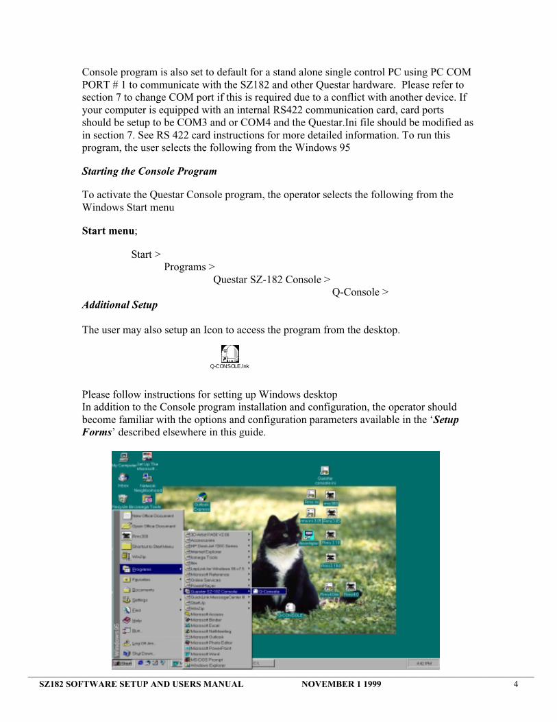
The user may also setup an Icon to access the program from the desktop.
Please follow instructions for setting up Windows desktopIn addition to the Console program installation and configuration, the operator shouldbecome familiar with the options and configuration parameters available in the ‘SetupForms’ described elsewhere in this guide.
Q-CONSOLE.lnk

_________________________________________________________________________________________________________________SZ182 SOFTWARE SETUP AND USERS MANUAL NOVEMBER 1 1999 5
When the Console program is activated, the operator is presented with a display calledthe Console Window, which initially fills the Windows Desktop. The Console Windowprovides the work area for all other control and setup forms, which are can be activatedand displayed. Current program status is displayed in the Status Bar located at thebottom of the Console window. All control and setup forms can be activated by the usingthe Menu Bar located along the top of the Console window some forms can be activatedby clicking on the bottom bar displayed information.
Status BarThe Status Bar is located at the bottom of the Console window and provides informationon general processing status, Pan unit Azimuth and Elevation positions, Scope unit filterand lens selections, Enclosure pressure, SZ182 temperature and SZ182 voltage. It alsoshows if the SZ182 and Pan units are online and actively communicating with theConsole program (dark numbers). If the numbers gray then the units are off line ortemporarily handling data received from the host computer. In addition, the Pan / TiltControl form can be activated by double-clicking either the Az or El portions of theStatus Bar. Likewise, double-clicking either the Lens or Filter portions of the Status Barcan activate the Scope Control form. The status bar may change depending on equipmentpurchased.
Console Windows
Menu Bar
Status Bar
COMM ACTIVEPAN UNIT ON LINE
COMM ACTIVESZ182 ONLINE
_________________________________________________________________________________________________________________SZ182 SOFTWARE SETUP AND USERS MANUAL NOVEMBER 1 1999 6
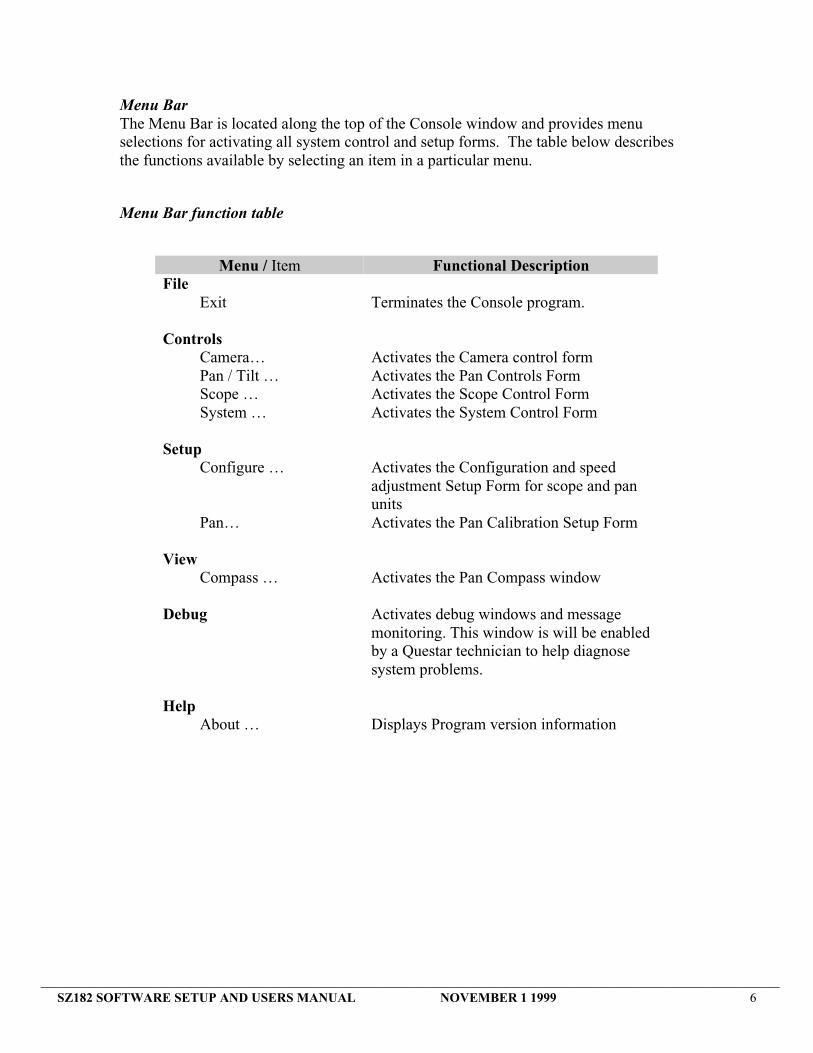
Menu BarThe Menu Bar is located along the top of the Console window and provides menuselections for activating all system control and setup forms. The table below describesthe functions available by selecting an item in a particular menu.
Menu Bar function table
Menu / Item Functional DescriptionFile
Exit Terminates the Console program.
ControlsCamera… Activates the Camera control formPan / Tilt … Activates the Pan Controls FormScope … Activates the Scope Control FormSystem … Activates the System Control Form
SetupConfigure … Activates the Configuration and speed
adjustment Setup Form for scope and panunits
Pan… Activates the Pan Calibration Setup Form
ViewCompass … Activates the Pan Compass window
Debug Activates debug windows and messagemonitoring. This window is will be enabledby a Questar technician to help diagnosesystem problems.
HelpAbout … Displays Program version information

_________________________________________________________________________________________________________________SZ182 SOFTWARE SETUP AND USERS MANUAL NOVEMBER 1 1999 7
Camera Control FormThe Camera Control form provides for the selection of the camera you want to use andcamera internal control via RS 232 control if camera is equipped and controllable andwas purchased as an upgrade. Day, Night and or if equipped a third camera (auxiliary)can be selected. The selection of cameras will depend on camera purchased and availableto user. Optional control settings for performance levels for the currently active cameracan be selected and adjusted to improve camera performance if that function is available.The current finder is a standard 1/3 “ format CCD that is active at all times. It is a fixedfocus finder with an internal AGC circuit. The Camera Control form is shown below.Un-highlighted group areas mean that this option or function is not installed or supported.
Control Forms
SELECTS A CAMERAAND DISPLAYSCURRENT CAMERAIN USE.
SHOWS THAT OPTIONALCAMERA FUNCTIONS ARENOT AVAILBLE

_________________________________________________________________________________________________________________SZ182 SOFTWARE SETUP AND USERS MANUAL NOVEMBER 1 1999 8
Pan Controls FormThe Pan Controls form provides for the control of the Pan/Tilt unit including directionalcontrol, setting and selecting Azimuth and Elevation presets, moving to HOME position,moving directly to a position based on Range/Bearing (GOTO), and SETUP to adjustvelocity and acceleration. Pan position displayed information may not be accurate untilthe system is setup and calibrated to its local environment (reference position) see SetupPan forms. The Pan Controls form is shown below.
The Pan/Tilt buttons provide directional controls for moving left, right, up and down.The Pan/Tilt buttons with a single arrow are used for normal movement. One left mouseclick on the button will start the motion until the stop button is pressed. Multiply clickson one of these buttons will accelerate Pan unit in the direction indicated by the arrowuntil the user clicks on stop, pan unit reaches a limit or decelerates to a stop by repeatedquick clicking on the opposing direction button. Movement will always continue at thisfinal velocity until the “Stop” button is clicked or the Pan unit reaches a limit. ThePan/Tilt buttons with the double arrows are used for “warping” type motion. When thesebuttons are clicked, the pan unit will accelerate to a predefined final velocity in thedirection indicated by the arrow. Movement will continue until the “Stop” button isclicked or the Pan unit reaches a limit. The final velocity and acceleration is determinedby the velocity and acceleration selected by user. Please refer to Velocity andacceleration settings.
The Presets buttons are provided for setting and selecting up to five (5) Azimuth andElevation pairs. When a Set button is clicked, the current Azimuth and Elevationpositions are saved and indicated on the Preset button located to the left of the Set button.When the Preset button is clicked, the Pan unit will be positioned at the Azimuth andElevation indicated on the button. The Set button will save position and store in CPURam.
ONE PRESS TO FAST SPEED
ONE PRESS TO START MOTIONMULTIPLE PRESSES TO RAMP SPEEDUP.
PRESSINGTHESEBUTTONSWILLMOVE TODISPLAYEDPRESETPOSITON
PRESSING THISBUTTON WILLSET OR RESETAND STORE THECURRENT PANPOSITON

_________________________________________________________________________________________________________________SZ182 SOFTWARE SETUP AND USERS MANUAL NOVEMBER 1 1999 9
The HOME button provides for the one step positioning of the Pan unit to a previouslydefined Azimuth and Elevation position. This position is set differently and is generallyuses as a specific reference position that the system can be moved to check systemaccuracy. It also can be the most commonly used position. The Home position actuallygives the user a sixth preset position. The home position is defined by using the PanControl Setup Pan form that is described under the Section “Setup Forms” below. As youcan see this position can not be changed as in the Presets above. It requires you to moveto a different form. You generally will enter this position when you calibrate the Pan/ Tiltunit at initial startup.
The GoTo button provides for the quick positioning of the Pan unit based on a operatordefined Bearing (degrees), Range (meters) or elevation angle entry. When the GoTobutton is clicked, a dialog box asking for Bearing and Range is displayed to the operator.See View selection later in this document for more information about GoTo.
The Setup button provides a method of activating the Pan Control Setup form, whichallow the user to change velocity and acceleration settings. See Section “Setup Forms”.
The Console window below shows the some of the forms described above. Please reviewthe Setup form section 5 for a better under standing of system control and function.
SLOW FAST

_________________________________________________________________________________________________________________SZ182 SOFTWARE SETUP AND USERS MANUAL NOVEMBER 1 1999 10
Scope Control FormThe Scope Control form provides for the control of the Scope Automatic Light Control(ALC) manual and auto, Focus, Parfocal, Lens, Filter selection and Lens Cap control.The Scope Control form is shown below.
The ALC Controls provide for the options selection of either Automatic or Manual ALC.While in Manual ALC the left and right arrow buttons are used to control the light level.When the buttons are depressed by holding down the left mouse button, the ALC willopen or close in the direction indicated by the arrows (Lighter or Darker) until the mousebutton is released. The level meter provides a relative indication of the current light levelneutral density selected. If you purchased the optional Automatic light control module thefollowing control function will be available to the user.
When the Auto mode is selected the light and dark button are used to set the automaticfunction threshold of light and darkness video level on an electronic circuit built into theSZ182 electronic package. The auto mode will automatically adjust to varying lightconditions to keep the video system from over or under exposing. This keeps user inputto a minimum so the user can do other functions. The user can vary the sensitivitythreshold by holding down the light or dark buttons. When you select the manual modethe threshold settings are saved and will be used again when you switch back to auto.There will be certain conditions that cause a constant oscillation of density filters, if this
FINE FOCUS CLICK
MEDIUM FOCUSCLICK
COARSE FOCUS DRAG
OPENS NEUTRAL DENSITY FILTERSAND LIGHTENS AUTOMATIC THRESHOLD
CLOSES NEUTRAL DENSITY FILTERSAND DARKENS AUTOMATIC THRESHOLD
DENSITY INDICATORLEVEL METER
CLICK TO TURNON/OFFX = PARFOC ON

_________________________________________________________________________________________________________________SZ182 SOFTWARE SETUP AND USERS MANUAL NOVEMBER 1 1999 11
occurs and is distracting to the user then click manual button to hold current densityposition.
The Focus controls provide for fine and coarse adjustment of the Scope focus. Clickingor holding the left mouse button down on the arrows on the slide bar gives the operatorvery fine adjustment of the focus. Clicking between the arrow and the indicator bar givesa quicker (medium) focus adjustment. The operator can also drag the indicator to anyposition within the slide bar to obtain coarse adjustment of the focus.
The ‘Set ParFoc’ button saves the current focus position for the currently selected Lens.The user can select any Lens and focus position and then save this combination bypressing set. Only one focus position can be stored for each lens. Pressing the set willover write previous data stored. The most common use of this function is to store infinityfocus settings for each lens. The ‘Parfoc On’ check box indicates the current status ofParFocalization, and allows the operator to turn Parfocalization on or off. WhenParFocalization is turned on, the focus position saved for each Lens is displayed belowand to the left of each Lens option. When you turn on Parfoc the focus will automaticallymove to the stored focus position of Lens that is currently selected. When Parfoc is “On”the stored position under the lens is P0000 then there is no stored data. Manual focus isalways available using the focus buttons as described above. If you want to return to astored focus position just turn Parfoc Off then On.
The Lens and Filter options provide for display of current settings and allow the operatorto select different combinations of Lens/Filter pairs. With ParFocalization turned on, theselection of a Lens option will also automatically move the focus to the previously savedfocus position indicated below and to the left of the Lens option. The Current lens selectis also shown on the bottom Status bar. Remember also that you can turn on the ScopeControl form by double clicking on these displayed values.
The descriptions of each of the Lens / Filter options can be configured by the operator byactivating the ‘Configuration Setup Form’ described elsewhere in this guide. The usercan change the names of these items or enable or disable. Please refer to Software set andConsole .INI file shipped with each unit. Please be aware that changing these settings willnot change actual hardware installed by Questar. It will only change what is displayed.
The Lens Cap button opens or closes the SZ182 Lens cap if it is installed and configuredfor your system. The activation button will determine the Lens cap position. If the buttondisplays OPEN then the cap is closed. If this button or text is gray then the function isnot available or has been disabled.
_________________________________________________________________________________________________________________SZ182 SOFTWARE SETUP AND USERS MANUAL NOVEMBER 1 1999 12
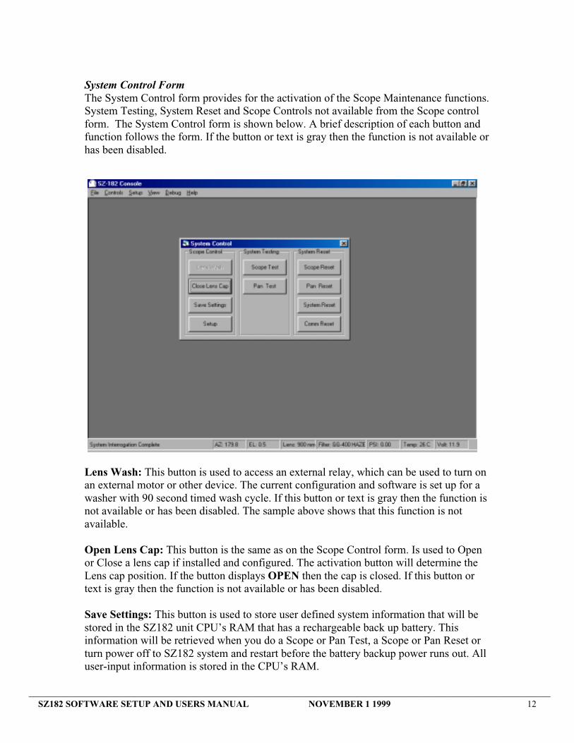
System Control FormThe System Control form provides for the activation of the Scope Maintenance functions.System Testing, System Reset and Scope Controls not available from the Scope controlform. The System Control form is shown below. A brief description of each button andfunction follows the form. If the button or text is gray then the function is not available orhas been disabled.
Lens Wash: This button is used to access an external relay, which can be used to turn onan external motor or other device. The current configuration and software is set up for awasher with 90 second timed wash cycle. If this button or text is gray then the function isnot available or has been disabled. The sample above shows that this function is notavailable.
Open Lens Cap: This button is the same as on the Scope Control form. Is used to Openor Close a lens cap if installed and configured. The activation button will determine theLens cap position. If the button displays OPEN then the cap is closed. If this button ortext is gray then the function is not available or has been disabled.
Save Settings: This button is used to store user defined system information that will bestored in the SZ182 unit CPU’s RAM that has a rechargeable back up battery. Thisinformation will be retrieved when you do a Scope or Pan Test, a Scope or Pan Reset orturn power off to SZ182 system and restart before the battery backup power runs out. Alluser-input information is stored in the CPU’s RAM.

_________________________________________________________________________________________________________________SZ182 SOFTWARE SETUP AND USERS MANUAL NOVEMBER 1 1999 13
The following is stored when the user presses the Save Settings button.
Scope unit stored information includes: DefaultParfocal focus positions for each lens P0000Parfoc ON/OFF offFocus current position farLens and Filter current positions 900 and openVelocities and Accelerations 3/4ALC ON/OFF off
This button does not store Pan information. The Pan unit stores this information whenthe user saves or Sets any placement position. These buttons are Set Home, Preset Setand Reference Position Set. The Pan unit stored information includes:
Pan unit stored information includes: DefaultReference Position and Calibration noneHome _ travelPresets left limit, down limitVelocities and Accelerations _, 1/4
Battery backup: Both Pan and Scope units are equipped with internal batteries that arerecharged when unit has power. Battery backup power should last for approximately 48hrperiod if the batteries are fully charged. If the system is not turned back on within thisperiod all above information will be lost and hard coded CPU default settings will beused. The battery back up condition is monitored and checked when a TEST is initiated.During this test the CPU looks for stored data in the backup RAM. If there is no storeddata present or it is corrupted then the battery may be bad. There must be storedinformation in this RAM or this test will mark BATTERY – Fail. Refer to aboveparagraph for how to save information.
Setup: This button opens the Configuration Setup Form. This form allows the user tochange or enable certain system functions. All motor velocities and acceleration profileare set from this form. It also displays system address information and current Lens andFilter descriptions. See Configuration Form for more detailed information.
Scope and Pan Test: Pressing these buttons will initiate a SZ182 or a Pan self testsometimes referred to as a BIT (Built In Test). It will test all basic function and reportback a status. During this test all motors and limits will be tested. This test will return theSZ182 to its user-defined settings as determined by stored information in the CPU’sRAM. Refer to Save Settings above. The italicized information will be the placement ofunits after the test is completed. If information is corrupt or not available, it will usedefaults. These tests do not need to be used unless you suspect a problem with either theSZ182 or the Pan unit. During any Test or Reset the unit under test will not be accessibleuntil the test is completed. The tests and or resets could last as long as 2 or 5 minutesdepending on installed components. The display below is a sample of what will be

_________________________________________________________________________________________________________________SZ182 SOFTWARE SETUP AND USERS MANUAL NOVEMBER 1 1999 14
displayed during the test. It will display Testing, Pass, Fail or N/A., if your system is notconfigured or does not have the appropriate hardware it will display N/A. Please note thatthere are two windows for each BIT test displayed for demonstration purposes only. Theyare testing and the completed. When this test is running the screen will update as the testsare completed. If certain functions fail they will be disabled and unavailable to user forcontrol during system use. If a fail is displayed the system may need repair. Please referto system failure and trouble section 10.
Scope and Pan Reset: These buttons will start a built in reset function for the itemselected. It has similar function to tests above but has more error correction value. Resetwill try and correct errors with SZ182 or Pan unit. It will access the CPU’s Ram data thenrestore unit to correct stored values and startup positions. As with the BIT the italicizedinformation will be the placement of units after the reset is completed. If information iscorrupt or not available, it will use defaults. This test should be done if a failure isdetected during the Test function. This test will cause a hardware reset and limit to limitexcursion on reset items.
Comm reset: This button will initiate a communications reset from PC to CPU’s onSZ182 and Pan unit it will also remove bad data and reestablish communication and askfor an individual status update form each unit. It will remove corrupted information andtry and establish a Comm Link between PC and external devices. Communicationsbetween devices is always active as long as SZ182 or Pan unit has power. The PC andConsole program will always try and establish a Comm link to external devices. Whenthe external device is turned on it will go through a hand shaking routine. The PC and

_________________________________________________________________________________________________________________SZ182 SOFTWARE SETUP AND USERS MANUAL NOVEMBER 1 1999 15
Console software will acknowledge and then bottom status display bar will becomeactive (Dark Numbers) see sample below. There is no display box. Use this if you havetrouble with communication link between console and system or your bottom statusdisplay is not responding or updating to commands. Closing Console program andrestarting program has a similar effect. The Console program will initiate a system searchfor devices and initialize and establish communications between Console program anddevices.
Communication to SZ182 and Pan unit must be active in order to send and receive anycontrol information from Console to external devices. If you can control external devices(TX) but your display is inactive or none responsive there must be corrupted data beingreceived (RX) by the Console program. Conversely if you are receiving (RX) updatedinformation but can not control external devices, then there must be corrupted data beingtransmitted (TX) by the Console program. If a Comm reset or a program restart does notestablish an active Comm link then there is a communication problem. Possible problemsare the following: external device may not be turned on, the PC COM port is notconfigured correctly in the console.INI file, the PC COM port may not be active or thereis a break or high noise level in the RS422 communication lines between PC and externaldevice.
System reset: This button is used to reset system and clear battery RAM. Be ware thatthis reset button will erase all user defined and stored information that is present in theboth the SZ182 and Pan units CPU’s RAM and restore factory default settings. Thisbutton should only be used when the system has been corrupted to point where all otherTests and Resets fail to recover the units.
COMMUNICATIONS ACTIVEPAN UNIT PRESENT
NO COMMUNICATIONSZ182 NOT PRESENT,LOST COMM LINK, BADDATA IN BUFFERS

_________________________________________________________________________________________________________________SZ182 SOFTWARE SETUP AND USERS MANUAL NOVEMBER 1 1999 16
Video WindowThe Video window, if this option has been activated, is located within the Consolewindow. This window provides real-time video from the Scope camera through the ITIframe-grabber board installed in the Console PC. This window can be sized, zoomed,and moved within the Console window. This window is only available when the Videooption has been integrated activated.
Configuration Setup FormThe Configuration Setup form provides for the status and selection of multiple Scope/Panunits (if available), setup of scope and pan unit accelerations and velocities, setting thedescriptions and availability of Lens and Filters. The enabling of optional equipmentsuch the Sun Sensor, Camera Switcher options, Temperature Control options is alsoavailable from this menu. Clicking on the item tab will allow switching between Pan andScope. Clicking the OK or APPLY button will save the changes. Motor speed andvelocity changes will not take effect while a motor is moving. They will become effectiveon the next motion. The Configuration Setup form is shown below.
Setup Forms
EXTERNAL DEVICE ADDRESSAND STATUS
SLOWER
FASTER
AIR CONDITIONER ANDHEATER CONTROL AREA
SUN SENSOR WARNINGDISPLAY
_________________________________________________________________________________________________________________SZ182 SOFTWARE SETUP AND USERS MANUAL NOVEMBER 1 1999 17
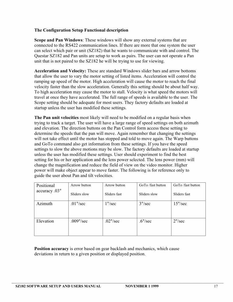
The Configuration Setup Functional description
Scope and Pan Windows: These windows will show any external systems that areconnected to the RS422 communication lines. If there are more that one system the usercan select which pair or unit (SZ182) that he wants to communicate with and control. TheQuestar SZ182 and Pan units are setup to work as pairs. The user can not operate a Panunit that is not paired to the SZ182 he will be trying to use for viewing.
Acceleration and Velocity: These are standard Windows slider bars and arrow bottomsthat allow the user to vary the motor setting of listed items. Acceleration will control theramping up speed of the motor. High acceleration will cause the motor to reach the finalvelocity faster than the slow acceleration. Generally this setting should be about half way.To high acceleration may cause the motor to stall. Velocity is what speed the motors willtravel at once they have accelerated. The full range of speeds is available to the user. TheScope setting should be adequate for most users. They factory defaults are loaded atstartup unless the user has modified these settings.
The Pan unit velocities most likely will need to be modified on a regular basis whentrying to track a target. The user will have a large range of speed settings on both azimuthand elevation. The direction buttons on the Pan Control form access these setting todetermine the speeds that the pan will move. Again remember that changing the settingswill not take effect until the motor has stopped and told to move again. The Warp buttonsand GoTo command also get information from these settings. If you have the speedsettings to slow the above motions may be slow. The factory defaults are loaded at startupunless the user has modified these settings. User should experiment to find the bestsetting for his or her application and the lens power selected. The lens power (mm) willchange the magnification and reduce the field of view on the video monitor. Higherpower will make object appear to move faster. The following is for reference only toguide the user about Pan and tilt velocities.
Positionalaccuracy .03°
Arrow button
Sliders slow
Arrow button
Sliders fast
GoTo /fast button
Sliders slow
GoTo /fast button
Sliders fast
Azimuth .01°/sec 1°/sec 3°/sec 15°/sec
Elevation .009°/sec .02°/sec .6°/sec 2°/sec
Position accuracy is error based on gear backlash and mechanics, which causedeviations in return to a given position or displayed position.

_________________________________________________________________________________________________________________SZ182 SOFTWARE SETUP AND USERS MANUAL NOVEMBER 1 1999 18
Lens/ Filter Setup: The user does have the ability to rename these to suite their need.Questar supplies a custom configuration and Consule.INI file for each system shipped.Please remember to keep a backup copy of this file to resort system to Questar suppliedsetting. The descriptions listed are actual hardware Questar installed into the systemwhen purchased. The user can disable a specific Lens or Filter if he decides not to use it.When it is disabled the system will skip that selection and not allow the user to access itfrom the Scope Control form.
Sun Sensor: This button will enable or disable the Console program to be notified by theexternal optional hardware that the Sun Sensor is activated. When the sun sensor isactivated the video main system will momentarily go blank and a window message willappear to notify the user if this button is checked. When the sun shutter opens themessage will disappear. The sun sensor system is set up to close off the optical path infront of the main camera if it detects too much sunlight to keep the main camera frombeing damaged. The finder camera does not have this protection. The sensitivity isfactory set to engage when the scope unit is in close proximity to the sun approximately±4°. This option is an internally controlled system that has not user input or override.The only way to open the shutter when closed is to move scope unit away from sun. Ifyou did not purchase this option then you should not click this option. It may cause thewarning windows to pop up by mistake. See warning message section later in thismanual.
Camera Switcher: This button will enable the Console program to control a thirdcamera or a switching stage if the hardware is installed in the SZ182 system. It mayactivate the Auxiliary camera control button depending on installed hardware. If thehardware is not installed this button will not function even if it looks active on theCamera control form.
Temperature Control: Temperature control is and optional software and or hardwareupgrade. You must purchase the hardware in order to have control from this area. TheSZ182 enclosure must be outfitted with the Peltier AC and or AC/Heating unit to havethe ability to change enclosure temperatures.
Enable/Disable button will enable the user to activate SZ182 CPU on board temperaturecontrol and allow the user to enter values to turn on the air conditioner and heater unitinside the SZ182 unit. If you Disable CPU control, the air conditioner and heater unitwill work from its own built-in protection thermostat. The current hardware temperaturesettings are 35° C to turn on air conditioner unit and 10° C to turn on heater unit.
Hi: will let the user set values from 29 to 34 ° C. When the internal temperature reachesthis value the air conditioner will turn. It will stay on until the internal temperature islowered 2 ° C from the turn on setting.
Lo: will let the user set values from 11 to 16° C. When the temperature raises 2 ° C theheater will turn off.

_________________________________________________________________________________________________________________SZ182 SOFTWARE SETUP AND USERS MANUAL NOVEMBER 1 1999 19
Temperature Control setting should be set once and only adjusted if required. Allinternal electronics are rated at least to 50°C.
Please refer to Setup and Install hardware manual and the specific data book for thePeltier air conditioner and heater unit if you need more specifics about this unit.

_________________________________________________________________________________________________________________SZ182 SOFTWARE SETUP AND USERS MANUAL NOVEMBER 1 1999 20
Setup Pan Control FormThe Pan Control Setup form provides for the setup of the Pan unit Reference Position,Home Position, and Scope Altitude (height above sea level in meters). The Pan ControlSetup form is shown below. Access this via the Setup drop down menu and click on Pan
The Reference Position is used to determine a known reference point for calibrating thePan unit to its actual compass location. When the ‘Set…’ button is clicked in theReference Position, the following form is displayed;

_________________________________________________________________________________________________________________SZ182 SOFTWARE SETUP AND USERS MANUAL NOVEMBER 1 1999 21
You will now need to open the Pan control form to position Pan unit. Move the Pan unituntil you have acquired your known target. Center the target on your monitor and zoomup to medium power say 2400mm. Reposition Pan unit to center target on monitor. Nowenter the compass Azimuth and elevation information and save to set. Azimuth values aredegree headings from a compass, which range from 0 to 359.9 degrees. Elevation valuesare from –15 to + 15 degrees. There are many ways to calibrate Pan unit. The moreaccurately you calibrate the unit the better position display information you will get. Ifthere is no known target, you will have to calibrate the Pan unit with a precision compassand precision level or inclinometer. The procedure is as follows:
Move Pan unit to mid points in azimuth and elevation between limits, this position willpoint the viewing end of the SZ182 away from the pan power cable and place the SZ182close to horizontal. This does not have to be exact. Generally on first power up the Panunit will move to mid points if there is no stored information in RAM. Refer to Pan unitinstallation instructions for viewing area setup and placement.
Go out to Pan unit and take position information manually. Use the compass to get areference azimuth position in degrees. The viewing end of the SZ182 is where the scopewill be pointing. You will need to determine this direction in relationship to a compassheading. If the SZ182 is pointing east the azimuth will be 90. If pointing south it will be180. West =270, North = 0
Use a level or inclinometer to determine tilt angle in + or – degrees. If the viewing end ofSZ182 is tilting up or above level then the angle will be a (+) tilt degree. Conversely if itis pointing down to ground then it will be a (–) tilt angle.
Record all information and then enter data into above setup screen and click save. Afteryou do this, the Pan unit will calibrate its positional information to coincide with the datathat was entered. Your bottom status display bar will now show you where you arelooking. It should be the information you just entered. Now, the user should find alandmark or a target such as a building by moving the Pan unit until it is displayed on themonitor. Record the displayed information from the bottom status display and save forfuture use. Please use the page at rear of this manual to record your data.
This information can be used to setup Pan unit if the RAM is erased or becomescorrupted. You would move Pan unit to display the landmark on monitor and then followPan unit setup procedures above. Enter the azimuth and elevation information into thesetup screens and the system will be calibrated. In most cases this position will be set toHome.

_________________________________________________________________________________________________________________SZ182 SOFTWARE SETUP AND USERS MANUAL NOVEMBER 1 1999 22
The Home Position is used to provide a one step method for moving the Pan unit to apreferred Azimuth and Elevation. When the ‘Set…’ button is clicked in the HomePosition Setup it will store this position as Home. The following form is displayed.
Home can be any point that you desire but may be a point of importance (landmark) toverify pointing and reposition accuracy. If you set home in this fashion you will be ableto verify Pan accuracy by just pressing the Home button on the Pan control form. Homeposition will also become the startup position for Pan Test and Pan Reset.
The Scope Altitude (height above sea level in meters) is used as a reference point whenthe Pan Controls form ‘GoTo’ function is used to position the Scope based on Bearingand Range to a target. When the ‘Set…’ button is clicked in the Scope Altitude group,the following form is displayed. Enter the appropriate information and then save.
All the above settings and entered information can be changed by the user at any time.Once this information is changed it will change all related positional displays. The Pantest and reset will not effect this information. This information will only be removedwhen “System Reset” button is used in the System control form or the battery backupRAM has been lost.

_________________________________________________________________________________________________________________SZ182 SOFTWARE SETUP AND USERS MANUAL NOVEMBER 1 1999 23
Compass: Is a visual GUI compass display that tells you where the SZ182 is pointing orviewing. The above Pan setup forms have now oriented the scope to a compass heading ifyou have set the reference position. If you move the pan unit the compass will move andupdate to follow actual motion. This is useful reference tool to assist the user in getting ageneral idea of where he is looking.
Compass functional tools: These tools are available as an upgrade on some units. Theywill allow the user to drag and drop the directional pointer or point to a location and clickto move pan unit. Placing the mouse pointer on the compass will display a position youwant it to move to, click the mouse to move. This is a similar function as GoTo but not asaccurate.
View
MOUSE POINTER ANDPOSITION DISPLAY

_________________________________________________________________________________________________________________SZ182 SOFTWARE SETUP AND USERS MANUAL NOVEMBER 1 1999 24
GoTo: This is very useful function and can be used to point the system at a target if youknow the targets compass location and range (distance). If the user were using a radarsystem he would just enter the information from his radar into the appropriate boxes andclick GoTo. The Pan unit will move the system to the correct location and the target willnow be on the video screen. From this same screen the user can also adjust position bychanging entered information by small amounts. If the user only wants to changeelevation he could click on the angle button and then change displayed angle setting, thenpress GoTo. As shown above the User has the ability to have multiple active windows tocontrol the Pan Unit.
The GoTo screen can also be used to determine Compass heading and range to a target.If the user finds a target while moving the Pan unit, he can open the GoTo screen and theinformation will be displayed.
GoTo accuracy is based on the information that the user entered in the Pan Setupwindows. It uses this information to triangulate range (distance), angle and bearing(compass heading). The internal calculator uses standard 90-degree triangle informationand does the calculation for you. Range will display Horizontal when the target is atinfinity, meaning the elevation angle is 0 and that the elevation is parallel to the ground.The following diagram depicts the basic concept.
Distance- Range
Scope Height
Infinity
S
- Degree
+ Degree

_________________________________________________________________________________________________________________SZ182 SOFTWARE SETUP AND USERS MANUAL NOVEMBER 1 1999 25
Console INI file: The Console software uses this file when the user starts the QuestarSZ182 Console program. This file sets up program displayed information, COM port andenable some hardware function. The most important function in this file is the setup ofCOM port. This port is how the software will communicate with the SZ182 and Pan unit.
Changing COM port: The installation software will automatically install Consolesoftware and support drivers to control communication. These drivers will supportWindows 95, 98 and NT. The installation process will set the COM port to COM 1,which is the most common port available. You will have to check your computer todetermine if this port is available. Some older systems use this port to control the mouse.If this is the case you will have to modify the .INI settings to change to next availableCOM port. See the following sample to demonstrate this change.All the user has to do is change “Port=1” to the port that is available on your PC. Theother settings should not be changed unless you are directed to do so by Questar.
[DataComm]Modem=0Port=1 ;;;( 1,2,3,4)Mode=9600,N,8,1Protocol=KermitDialingTimeout=25MaxReSend=5FailMax=1TimeOut=200
Enable hardware and equipment: There are many lines of information within this filethat will change as you change configurations within the program itself. They will changewhen you close the Console program automatically. Refer back to Configuration menufor user information input. Questar recommends that no other settings be changed. Allcorrect information pertaining to your system is contained in the Custom .INI file shippedwith your unit. Changing settings may adversely effect the function of your system.
Console INIsetup

_________________________________________________________________________________________________________________SZ182 SOFTWARE SETUP AND USERS MANUAL NOVEMBER 1 1999 26
Multi-Console ConfigurationThe Console program is capable of running as either the Main Console to the Questar SZ-182 Scope and Pan system, or as a Subordinate Console in a Multi-Console configurationas pictured below.
Main Console
Main Console
COM 1 COM 2
Subordinate Console 1
Subordinate Console 1
COM 1 COM 2
Subordinate Console 2
Subordinate Console 2
COM 1 COM 2
Subordinate Console 8
Subordinate Console 8
COM 1 COM 2
Null Modem Cable Null Modem Cable Null Modem Cableto Scope / Pan Units
After the installation process has completed, the Console program is configured as theMain Console. In order to designate the PC as a Subordinate Host in a Multi-Consoleconfiguration another step must be performed to complete the installation and setupprocess. The “Console Configuration Utility” program will be provided for this purposeso it can be loaded onto the PC if this upgrade was purchased. To run this program, theuser selects the following from the Windows.
Start menu;
Start >Programs >
Questar SZ-182 Console >Console Configuration Utility
Once the Console Configuration Utility program is started, the user is presented with thefollowing form;
Multi-Consolesetup

_________________________________________________________________________________________________________________SZ182 SOFTWARE SETUP AND USERS MANUAL NOVEMBER 1 1999 27
The user then selects either the “Main Console” or “Subordinate Console” options. If the“Subordinate Console” option is selected, then the user must select a Host number by theusing the arrow buttons. Once this is done, the user clicks on the “Save” button tocomplete the configuration of the Console program.

_________________________________________________________________________________________________________________SZ182 SOFTWARE SETUP AND USERS MANUAL NOVEMBER 1 1999 28
Setup Information Record sheet
Setup Information for Pan Unit
Landmark Description: _________________________________
Azimuth: ____________________________________
Elevation: ___________________________________
Altitude: ____________________________________
Range: _____________________________________
Setup Information for SZ182 Lens and Filter Display
Lens #1: __________________ Filter #1: __________________
Lens #2: __________________ Filter # 2: _________________
Lens # 3: _________________ Filter #3: __________________
Lens #4: __________________ Filter #4: __________________
Lens #5: ___________________ Filter #5: ____________________
_________________________________________________________________________________________________________________SZ182 SOFTWARE SETUP AND USERS MANUAL NOVEMBER 1 1999 29
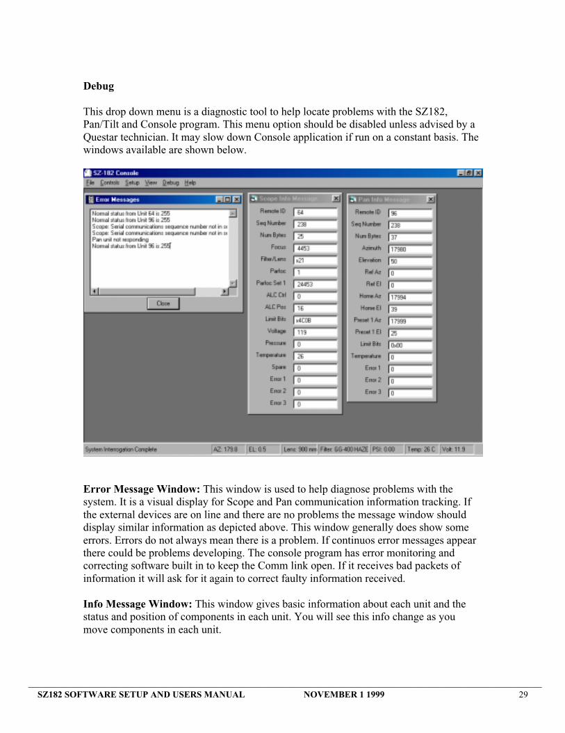
Debug
This drop down menu is a diagnostic tool to help locate problems with the SZ182,Pan/Tilt and Console program. This menu option should be disabled unless advised by aQuestar technician. It may slow down Console application if run on a constant basis. Thewindows available are shown below.
Error Message Window: This window is used to help diagnose problems with thesystem. It is a visual display for Scope and Pan communication information tracking. Ifthe external devices are on line and there are no problems the message window shoulddisplay similar information as depicted above. This window generally does show someerrors. Errors do not always mean there is a problem. If continuos error messages appearthere could be problems developing. The console program has error monitoring andcorrecting software built in to keep the Comm link open. If it receives bad packets ofinformation it will ask for it again to correct faulty information received.
Info Message Window: This window gives basic information about each unit and thestatus and position of components in each unit. You will see this info change as youmove components in each unit.

_________________________________________________________________________________________________________________SZ182 SOFTWARE SETUP AND USERS MANUAL NOVEMBER 1 1999 30
Warning Message Windows
The SZ182 Scope has several warning messages to alert the user that may effectoperation. The warning message windows must be closed to continue operation of thesystem. Clicking on the X button will close the warning message and allow the user toproceed with operation of the unit. These messages will reappear at predefined timeintervals to remind the user to correct the problem if it still needs attention. The followingare examples of messages and a brief description of function.
Pressure Warning:This message is to advise the user that the enclosure pressure is low. It will reappearevery couple of hours until the enclosure is pressurized back to more than .1psi. Thiswindow must be closed in order to proceed with any other control function. The Scopeand Pan will then function properly. This warning is only to advise the user to schedule aservice to check and pressurize the enclosure. The pressure inside the enclosure willchange hourly depending on the temperature outside and inside the enclosure. Thegeneral rule is a .02 psi variation / 1° C change in inside temperature. An increase intemperature will increase pressure while a decrease in temperature will decrease pressure.The enclosure is equipped with a pressure relief valve that will prevent the enclosurefrom over pressurization. This valve is factory set to .5 psi. The pressure sensor inside theSZ182 will display up to 1.0 psi. Please refer to the setup and install hardware manual forinformation about the enclosure pressurization and the pressure system.
Voltage Warning:This message is to advise the user that the SZ182 scope unit 12 VDC power supply isoutside of usual tolerances and may be experiencing some problem. It will reappear every30 minutes until the power is within normal specification. This window must be closed inorder to proceed with any other control function. The Scope and Pan will then functionproperly. The SZ182 scope unit will function properly from 10 VDC to 13.0 VDCregulated 6.5 AMP low noise power supply.
The pan unit power is not monitored.
Please refer to Setup and install hardware manual for more information on powersupplies and system power requirements. Both power supplies are fuse protected and mayrequire replacement if power fails.

_________________________________________________________________________________________________________________SZ182 SOFTWARE SETUP AND USERS MANUAL NOVEMBER 1 1999 31
Sun Shutter Activated:
Sun Shutter Activated:This message is to advise the user that the sun sensor system has activated. When thismessage appears, the SZ182 on board hardware has sensed that the unit is in closeproximity to the sun and will activate a shutter to close down the optical light path to themain camera. This will block the image to the main camera and make the video image goblank until it opens. The user has no control over this function if the hardware is installed.The only way to open the shutter is to move the SZ182 away from the bright object,which is illuminating the sensing unit. It will reappear every time the SZ182 is pointedtoward the bright object. You may disable the message by un-clicking the Sun Sensorbox in the Configure Setup area but you will not disable the hardware if you purchasedthis option. The sun sensor system does not effect the SZ182 finder system. The findersystem is always active if your have this option. It is a separate camera from the mainsystem camera.
Please consult the Setup and Install Hardware manual for more information about theSZ182 finder system.

_________________________________________________________________________________________________________________SZ182 SOFTWARE SETUP AND USERS MANUAL NOVEMBER 1 1999 32
USER INFORMATIONThe following information is meant to help the user and give a perspective to what isdisplayed on the video monitor. It is only meant as a guide and not information will be100% accurate.
Field Of ViewThe chart below will give a rough estimate of actual field of view seen on the videomonitor while using the SZ182 scope. The numbers to the right side are the lensselections available form the Scope Control form. The top numbers are distance inmeters. The numbers just under the distance is the camera chip size. You will have toknow what chip size is in the camera that is installed in the SZ182 unit. The numberunder the chip size is the approximate field width in meters. Please note the 200mm is theapproximate EFL of the finder system.
STEP ZOOM FIELD OF VIEWS (METERS)
75 METERS 1000 metersSZ-182
1/3CCD 1/2 CCD 2/3CCD 1" CCD FINDER 1/3CCD 1/2 CCD 2/3CCD 1" CCD FINDER200MM 1.84 24.50900MM 0.40 0.53 0.74 1.48 5.33 7.11 9.89 19.78
1450MM 0.25 0.33 0.46 0.92 3.31 4.41 6.14 12.282400MM 0.15 0.20 0.28 0.56 2.00 2.67 3.71 7.424000MM 0.09 0.12 0.17 0.33 1.20 1.60 2.23 4.456000MM 0.06 0.08 0.11 0.22 0.80 1.07 1.48 2.97
1500 METERS 5000 METERSSZ-182
1/3CCD 1/2 CCD 2/3CCD 1" CCD FINDER 1/3CCD 1/2 CCD 2/3CCD 1" CCD FINDER200MM 36.75 122.50900MM 8.00 10.67 14.67 29.67 26.67 35.56 48.89 98.89
1450MM 4.97 6.62 9.10 18.41 16.55 22.07 30.34 61.38 2400MM 3.00 4.00 5.50 11.13 10.00 13.33 18.33 37.08 4000MM 1.80 2.40 3.30 6.68 6.00 8.00 11.00 22.25 6000MM 1.20 1.60 2.20 4.45 4.00 5.33 7.33 14.83
10,000 METERS 20,000 METERSSZ-182
1/3CCD 1/2 CCD 2/3CCD 1" CCD FINDER 1/3CCD 1/2 CCD 2/3CCD 1" CCD FINDER200MM 245.00 490.00900MM 53.33 71.11 97.78 197.78 106.67 142.22 195.56 395.56
1450MM 33.10 44.14 60.69 122.76 66.21 88.28 121.38 245.522400MM 20.00 26.67 36.67 74.17 40.00 53.33 73.33 148.334000MM 12.00 16.00 22.00 44.50 24.00 32.00 44.00 89.006000MM 8.00 10.67 14.67 29.67 16.00 21.33 29.33 59.33
THE ABOVE NUMBER ARE IN METERS

_________________________________________________________________________________________________________________SZ182 SOFTWARE SETUP AND USERS MANUAL NOVEMBER 1 1999 33
Example: Approx. distance 5000m, chip size 2/3, the lens selected is 2400mm. Fieldsize would be approx. 18.3m
Using the chart above you can determine approximate size of object. Point the SZ182 atan object. If you know the distance then select the distance in meters from the chartabove. You can use an estimate for most purposes. You should know the camera chipsize. You would read down the column under the chip size and distance to determinefield width. You would then be able to estimate the target size by how much width thetarget fills up across the screen.
The target now fills about 1/3 of the video monitor across. You know from the chartabove that the field width is 18.3m. 1/3 of 18.3 meters is approximately 9 meters. Youknow that the target is about 9 meters wide.
The sample picture above depicts a target at 75 meter, 900mm lens, 2/3 CCD sensor anda target size of 10” x 12” (.25 X .3 m). The target is less than _ the field of .74m which isapproximately .37m.

_________________________________________________________________________________________________________________SZ182 SOFTWARE SETUP AND USERS MANUAL NOVEMBER 1 1999 34
Target Speed and Distance:
The chart below will give a rough estimate of target speed versus distance as seen on thevideo monitor while using the SZ182 scope. The numbers to the left side are distances totarget. The right is the linear speed of a target assuming the pan is rotating at a slowspeed. The colored lines represent the travel distance of a target in one (1) minute. Youshould now be able to refer back to the field of view chart to get an estimate of thedifferent lens selections and relative speed of target based on the Pan speed.
Approximate slowrotation speed.01degree/sec
10(16)
8(12.8
6(9.6)
4(6.4)
2 (3.2)
1 (1.6)
Distance in miles(meters)
Target speed inMPH, mile/hour (K/h)
.39 mph (.6)
.78 mph (1.2)
1.56 mph (2.5)
2.34 mph (3.7)
3.90 mph (6.2)
3.12 mph (5)
TRAVEL DISTANCE INMETERS INONE MINUTE
103
83
61
41
20
10
_________________________________________________________________________________________________________________SZ182 SOFTWARE SETUP AND USERS MANUAL NOVEMBER 1 1999 35
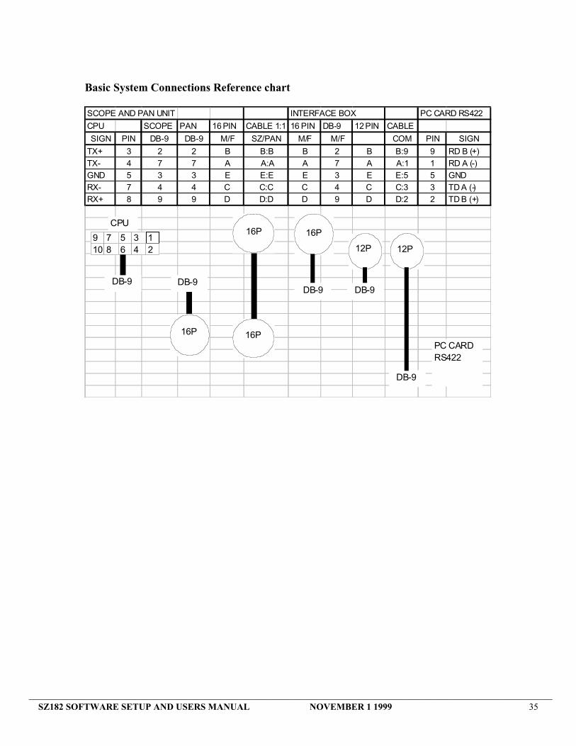
Basic System Connections Reference chart
SCOPE AND PAN UNIT INTERFACE BOX PC CARD RS422
CPU SCOPE PAN 16 PIN CABLE 1:1 16 PIN DB-9 12 PIN CABLE
SIGN PIN DB-9 DB-9 M/F SZ/PAN M/F M/F COM PIN SIGN
TX+ 3 2 2 B B:B B 2 B B:9 9 RD B (+)TX- 4 7 7 A A:A A 7 A A:1 1 RD A (-)GND 5 3 3 E E:E E 3 E E:5 5 GNDRX- 7 4 4 C C:C C 4 C C:3 3 TD A (-)RX+ 8 9 9 D D:D D 9 D D:2 2 TD B (+)
DB-9
16P 16P
16P 16P
DB-9 DB-9
12P9 710 8
56
34
12
DB-9
CPU
12P
DB-9
PC CARDRS422