Q196 Generation Interconnection - OATI · PDF file · 2015-04-22Please note that...
14
Q196 Generation Interconnection Interconnection Facilities Study Results APS Contract No. 52773 By Arizona Public Service Company Transmission Planning April 22, 2015 [Version 1]
Transcript of Q196 Generation Interconnection - OATI · PDF file · 2015-04-22Please note that...
Q196 Generation
Interconnection
Interconnection Facilities Study Results
APS Contract No. 52773
By
Arizona Public Service Company Transmission Planning
April 22, 2015
[Version 1]
Q196 Facilities Study APS Contract No. 52773
Page i
Q196 FACILITIES STUDY - TECHNICAL REVIEW
TABLE OF CONTENTS
Contents 1. Introduction ............................................................................................................................................ 3
2. Q196 Interconnection Facilities ............................................................................................................. 5
3. Cost Estimates ....................................................................................................................................... 7
3.1. Summary of Construction Time Estimates at the POI ......................................................................... 10
4. Request For Transmission Service ...................................................................................................... 12
5. Power Factor Requirements ................................................................................................................ 12
5.1 Reactive Support ................................................................................................................................. 12
Q196 Facilities Study APS Contract No. 52773
Page ii
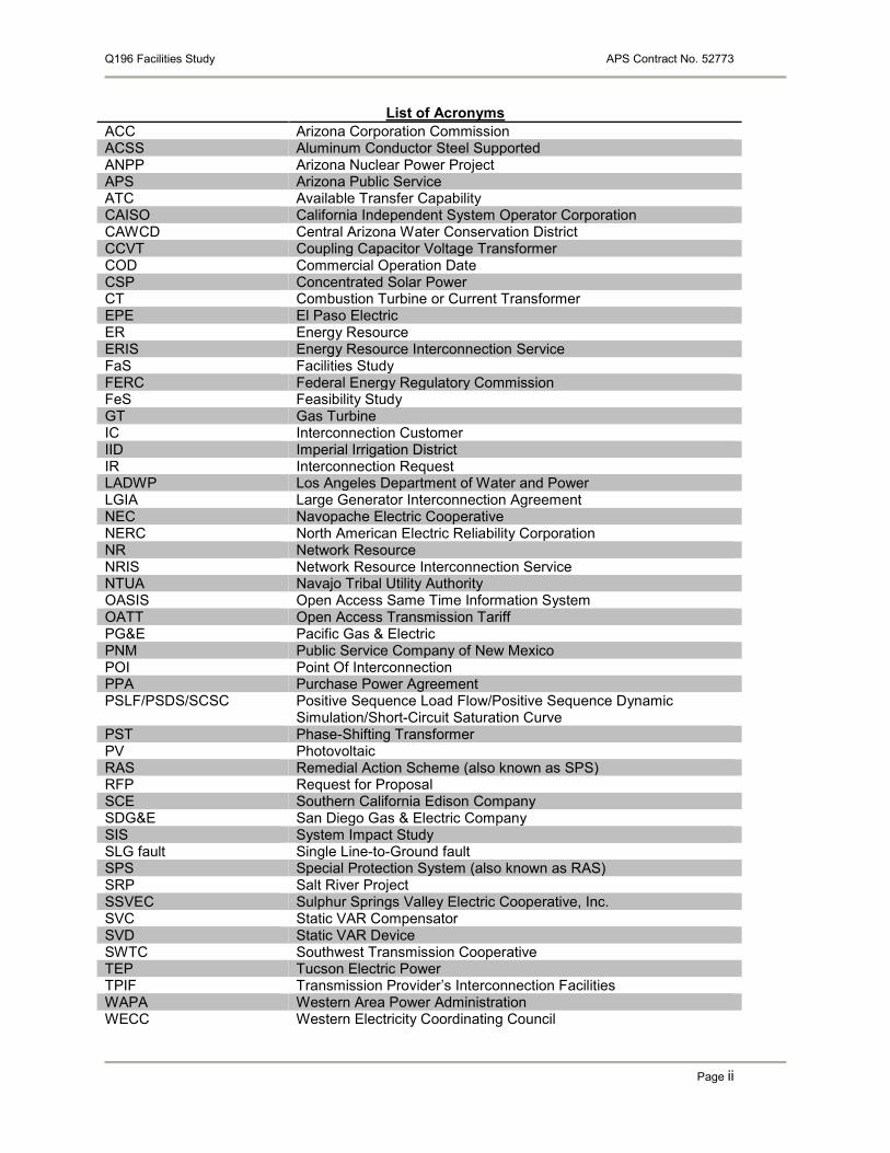
List of Acronyms
ACC Arizona Corporation Commission ACSS Aluminum Conductor Steel Supported ANPP Arizona Nuclear Power Project APS Arizona Public Service ATC Available Transfer Capability CAISO California Independent System Operator Corporation CAWCD Central Arizona Water Conservation District CCVT Coupling Capacitor Voltage Transformer COD Commercial Operation Date CSP Concentrated Solar Power CT Combustion Turbine or Current Transformer EPE El Paso Electric ER Energy Resource ERIS Energy Resource Interconnection Service FaS Facilities Study FERC Federal Energy Regulatory Commission FeS Feasibility Study GT Gas Turbine IC Interconnection Customer IID Imperial Irrigation District IR Interconnection Request LADWP Los Angeles Department of Water and Power LGIA Large Generator Interconnection Agreement NEC Navopache Electric Cooperative NERC North American Electric Reliability Corporation NR Network Resource NRIS Network Resource Interconnection Service NTUA Navajo Tribal Utility Authority OASIS Open Access Same Time Information System OATT Open Access Transmission Tariff PG&E Pacific Gas & Electric PNM Public Service Company of New Mexico POI Point Of Interconnection PPA Purchase Power Agreement PSLF/PSDS/SCSC Positive Sequence Load Flow/Positive Sequence Dynamic
Simulation/Short-Circuit Saturation Curve PST Phase-Shifting Transformer PV Photovoltaic RAS Remedial Action Scheme (also known as SPS) RFP Request for Proposal SCE Southern California Edison Company SDG&E San Diego Gas & Electric Company SIS System Impact Study SLG fault Single Line-to-Ground fault SPS Special Protection System (also known as RAS) SRP Salt River Project SSVEC Sulphur Springs Valley Electric Cooperative, Inc. SVC Static VAR Compensator SVD Static VAR Device SWTC Southwest Transmission Cooperative TEP Tucson Electric Power TPIF Transmission Provider’s Interconnection Facilities WAPA Western Area Power Administration WECC Western Electricity Coordinating Council

Q196 Facilities Study APS Contract No. 52773
Page 3
1. Introduction
Arizona Public Service Company (APS) performed this Generator Interconnection Facilities Study (FaS) in response to a 161 MW hybrid wind/solar photo-voltaic interconnection request by the Interconnection Customer (IC). The IC originally submitted a 360.80 MW interconnection request that was reduced to 161 MW, with 101 MW of wind production and 60 MW for Solar. The Customer is listed in APS’s Active Generator Interconnection Queue as queue number 196 (Q196). The purpose of the study is to provide cost and construction schedule estimates for the facilities needed to interconnect the IC’s proposed 161 MW hybrid wind/solar photo-voltaic generation facility into the jointly owned Navajo Southern Transmission System (NSTS) Moenkopi – Cedar Mountain 500kV line. The generation facility would be located on the Moenkopi – Cedar Mountain line approximately 26 miles from the Moenkopi substation. APS retained Utility System Efficiencies (USE) to perform the technical analysis portion of this FaS. The Interconnection Customer submitted an interconnection request to APS, which was accepted on May 5, 2011 and has already completed a System Impact Study. This Project is a FERC jurisdictional large interconnection request. The IC’s orginally requested Commercial Operation Date for Q196 was November 1, 2012. The Interconnection Customer submitted a revised requested Commercial Operation Date, as per the Facilities Study Agreement for Q196 for November 1, 2015. The IC’s requested date to have the interconnection initially energized in order to take back feed power is October 1, 2015. The projected construction duration for Q196 is 30 months. Due to the original in-service and commercial operation dates not being able to be met, APS will utilize the first available dates as shown in the construction milestones found in table 2 below. Please note that the Commercial Operation Date must be within the seven (7) years of the APS acceptance of the Interconnection Customer’s Interconnection Request. All reasonable efforts will be used by APS to meet the Interconnection Customer’s proposed project dates. The IC has requested interconnection along the Moenkopi – Cedar Mountain 500 kV line. The Point of Interconnection (POI) for this project will therefore be at the tap on the Moenkop – Cedar Mountain 500 kV line. For this specific interconnection request only, the NSTS owners have decided to allow the usage of a tap to the Moenkopi – Cedar Mountain 500 kV line. The owners expressly states that the usage of a tap for this interconnection does not set precedent for any future proposed interconnections. No new interconnection will be allowed to degrade the protection scheme for any NSTS facilities. The IC has chosen to interconnect with the Energy Resource Interconnection Service option. Delivery of the Q196 output beyond the POI would be on an “as-available” basis only. The delivery of the Q196 output would be subject to the firm or non-firm transmission capacity that may be available when a Transmission Service Request is made. Figure 1 shows a general depiction of the EHV system around Q196’s proposed POI.

Q196 Facilities Study APS Contract No. 52773
Page 4
Figure 1. Transmission System in the Q196 vicinity
Disclaimer Nothing in this report constitutes an offer of transmission service or confers upon the Interconnection Customer (“IC”) any right to receive transmission service. APS and other interconnected utilities may not have the Available Transmission Capacity to support the interconnection described in this report. It should also be noted that all results for the FaS are highly dependent upon the assumed topology and timing of new projects in the vicinity of the interconnection, which are subject to change.
Moenkopi 500 kV
34.5 kV
500 kV
26 miles 30 miles
R=0.002 X=0.080
0.690 kV
R=0.0076 X=0.0570
Pmax=100.8 MW Qrange=+/-48.83 MVAR
R=0.0076 X=0.0570
0.288 kV
R=0.0076 X=0.0570
Pmax=15 MW Qrange=+/-4.93 MVAR
0.288 kV
Pmax=15 MW Qrange=+/-4.93 MVAR
0.288 kV
Pmax=15 MW Qrange=+/-4.93 MVAR
0.288 kV
Pmax=15 MW Qrange=+/-4.93 MVAR
Cedar Mountain 500 kV

Q196 Facilities Study APS Contract No. 52773
Page 5
2. Q196 Interconnection Facilities In order to connect the Q196 project, facilities will be required for substation, line work, communications, land, and siting. The facilities required include:
Substation – Installation of a new 500 kV switchyard for a single breaker tap on the 500 kV Cedar Mountain – Moenkopi line. The switchyard will consist of:
o (1) 3 pole 500 kV breaker o (2) 500 kV switches o (1) 500 kV single phase SSVT o (1) single pole 500 kV breaker o (1) single pole 500 kV switch o (1) single pole 500 kV CT o (1) control house and associated relays, batteries, and chargers o (1) pad mount station power transformer feed from customer transformer tertiary o (1) diesel generator o (1) site security monitoring equipment o Associated structures / bus supports / fence
Station power will be provided by a 500 kV SSVT, with backup station power from customer transformer tertiary and standby generator. New relays will need to be installed at Moenkopi and Cedar Mountain to support new 3-point relaying.
Line work – materials, structures and construction activities needed to do the line drop from the Moenkopi – Cedar Mountain line tap to the new 500 kv switchyard.
Communications – Substation communications for high voltage substations requires two physically diverse communication paths. There will be one microwave path and one fiber optic path with fiber on the 500 kv line from Q196 to the Cedar Mountain substation. The communications costs for the Q196 project has been deemed network upgrades as these costs are required for the revised line protection schemes to function. The communications costs are on the transmission system and therefore beyond the POI. Thus the communications perform a network function and are deemed network upgrades rather than transmission provider’s interconnection facilities.
Relays – Work needed to replace the existing relays (L1, L2, L3) at Moenkopi and Cedar Mountain to support the 3 point relaying that will be required for the tapped interconnection.
Land – There would need to be land acquired for a substation site north of the 500 kV corridor near Valle, Arizona. Five (5) acres of land would be needed for the substation from the surrounding private and State-owned lands. Potential studies or permits that would need to be acquired includes title reports, appraisals, and environmental studies. Property purchase could range from 6 to 12 months. If condemnation is necessary the property purchase could be up to 2 years.
Siting – A certificate of Environmental Compatibility (CEC) will be required to interconnect the switchyard with the Moenkopi – Cedar Mountain 500 kV line. Completing the CEC will require cooperative efforts from both customer and APS and the CEC process is likely to take 8 to 12 months.
The total cost for the facilities required to interconnect the Q196 project is $9,270,719.

Q196 Facilities Study APS Contract No. 52773
Page 6
Figure 2 is a one-line diagram of the proposed configuration and interconnection of Q196’s project. In Figure 2, the Moenkopi – Cedar Mountain 500 kV line shown in black are the existing facilities. Figure 2 also depicts the Customer’s Interconnection Facilities which are shown in green. In Figure 2, the facilities shown in red are the Transmission Provider’s Interconnection Facilities (TPIF). APS will operate and maintain all the facilities shown in red up to the first structure outside of the substation fence, at which point the IC would pick-up ownership and responsibility for the line. Ownership of the TPIF shall be held by the Navajo Project Participants in proportion to their ownership in the Moenkopi – Cedar Mountain 500 kV transmission line. The IC is responsible for providing the full cost for the TPIF.
Figure 2. New Q196 Switchyard one-line
Q196 Facilities Study APS Contract No. 52773
Page 7
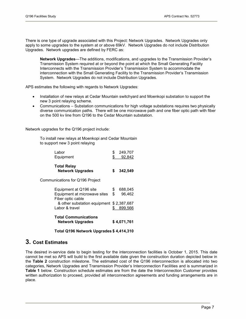
There is one type of upgrade associated with this Project: Network Upgrades. Network Upgrades only apply to some upgrades to the system at or above 69kV. Network Upgrades do not include Distribution Upgrades. Network upgrades are defined by FERC as:
Network Upgrades—The additions, modifications, and upgrades to the Transmission Provider’s Transmission System required at or beyond the point at which the Small Generating Facility Interconnects with the Transmission Provider’s Transmission System to accommodate the interconnection with the Small Generating Facility to the Transmission Provider’s Transmission System. Network Upgrades do not include Distribution Upgrades.
APS estimates the following with regards to Network Upgrades:
Installation of new relays at Cedar Mountain switchyard and Moenkopi substation to support the new 3 point relaying scheme.
Communications – Substation communications for high voltage substations requires two physically diverse communication paths. There will be one microwave path and one fiber optic path with fiber on the 500 kv line from Q196 to the Cedar Mountain substation.
Network upgrades for the Q196 project include: To install new relays at Moenkopi and Cedar Mountain to support new 3 point relaying Labor $ 249,707 Equipment $ 92,842 Total Relay Network Upgrades $ 342,549 Communications for Q196 Project Equipment at Q196 site $ 688,045 Equipment at microwave sites $ 96,462 Fiber optic cable & other substation equipment $ 2,387,687 Labor & travel $ 899,566 Total Communications Network Upgrades $ 4,071,761 Total Q196 Network Upgrades $ 4,414,310
3. Cost Estimates The desired in-service date to begin testing for the interconnection facilities is October 1, 2015. This date cannot be met so APS will build to the first available date given the construction duration depicted below in the Table 2 construction milestone. The estimated cost of the Q196 interconnection is allocated into two categories, Network Upgrades and Transmission Provider’s Interconnection Facilities and is summarized in Table 1 below. Construction schedule estimates are from the date the Interconnection Customer provides written authorization to proceed, provided all interconnection agreements and funding arrangements are in place.

Q196 Facilities Study APS Contract No. 52773
Page 8
Interconnection construction costs and timelines were estimated for Q196 based on the approximate location described above. These good faith non-binding cost estimates are applicable only to the APS system. This study reviewed all capacity, construction, flicker, protection and communications requirements to interconnect this FERC-jurisdicitional generation project. NERC (North American Reliability Corporation) requires that generation facilities provide a primary and secondary (back-up) communications path for data and control. This study does not specifically address any requirements for the Interconnection Customer Generating Facilities. However, the Interconnection Customer shall comply with all APS requirements for a generator operating in parallel with APS’s electrical system. Assumptions: The following assumptions were utilized in compiling the cost estimates for Q196:
I) Site Civil will include grounding, foundations and conduit only Land and civil engineering will be performed by the IC
II) Design Full scope of work attained Engineering and design activities will be performed by contractor Once drawing package is IFC, no drawings will need to be updated (i.e. modifications from other construction/maintenance activities which occur following issue of package)
III) Construction A mobile transformer will not be needed All substation construction and P&C activities will be performed by APS crew Per diem was added Will need to rent equipment, such as manlift; therefore, add equipment rental costs Account for some personnel going to Substation during construction or possible design. APS construction crew will be comprised of a 4-person crew, working 10 hour days, 4 days per week; no overtime APS P&C crew for wiring will be comprised of a 2-person crew, working 10 hour days, 4 days per week; no overtime
IV) P&C P&C will stay after the construction crews are done to finish all wiring and will put station in service
V) Exclusions Any construction outside of substation wall/fence is not included in this estimate. (i.e. overhead, underground, communications, etc…)

Q196 Facilities Study APS Contract No. 52773
Page 9
Table 1. Cost Estimates for Q196 - POI
Equipment Description Network Upgrades Transmission Provider's Interconnection Facilities
Q196 Substation Work $0 $3,556,433
Q196 Line Work $0 $ 925,476
Relay – Cedar Mountain, Moenkopi
$ 342,549 $ 0
Communications $4,071,761 $ 0
Siting $0 $ 352,000
Land $0 $ 22,500
Subtotal $4,414,310 $4,856,409
Grand Total $9,270,719
All Network Upgrade costs are subject to repayment in accord with FERC rules. It will be the responsibility of the interconnection customer to work with each of the NSTS owners individually to determine the specifics of how, if, when and under what circumstances the allocated share of Network Upgrades will be repaid. Costs for these Network Upgrades are estimated to be $4.41M. The estimate for the Transmission Provider’s Interconnection Facilities is $4.86M, none of which is subject to refund. The total estimated cost for the interconnection is $9.27M. Figure 2 identifies additions that are needed for the interconnection request. The owners of the NSTS are the United States of America (“US”), Arizona Public Service Company (“APS”), Department of Water and Power for the City of Los Angeles(“LADWP”), Nevada Power Company (“NVE”), Salt River Project Agricultural Improvement and Power District (“SRP”), and Tucson Electric Power Company (“TEP”). The ownership percentages for the Navajo Southern Transmission System Moekopi – Cedar Mountain 500kV line are: APS: 24.7% SRP: 38.3% *SRP for U.S: 23.7% TEP: 13.3% * SRP holds title for the use and benefit of the United States. Network Upgrades are typically repaid by APS via transmission service credits over a twenty year period. Any amount remaining at the end of the twenty years are repaid to the Interconnection Customer, including such interest as defined by FERC. PLEASE NOTE: The cost estimates exclude Interconnection Customer costs associated with obtaining permits, easements or income tax or other tax effect and and the cost associated with any Interconnection Customer-owned equipment required for the interconnection of the generators, including protective relaying and a visible open utility disconnect switch. In addition to the construction costs described above, there will be annual operation and maintenance expenses. The estimated cost of annual operation and maintenance expenses is as follows: Common Equipment/ Line Inspections - $3,000 annually
- Two inspections per year

Q196 Facilities Study APS Contract No. 52773
Page 10
- Relay maintenance (estimated at every 4-6 years) - Weed abatement spraying (estimated at 2 times per year)
Breaker Maintenance - $6,000 each time for:
- Overhaul (estimated once every 6 years) Additional actual costs will be charged for:
- Emergency maintenance and repair work such as breaker failure-to-close
3.1. Summary of Construction Time Estimates at the POI
The IC’s requested date to energize the interconnection facilities to receive back feed power is December 1, 2016. Table 2 is a preliminary design and construction timeline. Table 2 estimates that it will take approximately 30 months in order to site, certificate, design, permit, procure, and construct the required facilities to interconnect the Q196 project; putting the earliest possible date for the IC’s project to be energized at 30 months from the date all the appropriate agreements are signed and funded. Due to the original in-service and commercial operation dates not being able to be met, APS will utilize the first available dates as shown in the construction milestones found below. High level interconnection construction cost estimates for the facility interconnection are tabulated above. Construction schedule estimates are from the date the Interconnection Customer provides written authorization to proceed, provided all interconnection agreements and funding arrangements are in place.
Table 2. Q196 Construction Time Estimates at POI
LGIA
Milestones
This Milestone table represents APS’s best effort at targeting a high level construction and In-Service schedule per Interconnection Customer’s requested In-Service Date. Please note that the Commercial Operation Date must be within the seven (7) years of the APS acceptance of the Interconnection Customer’s Interconnection Request. This Schedule and its projected In-Service Date are subject to change due to potential issues with weather, permitting and other required criteria and activities which may cause unforeseen timing delays. Upon commencement of Project, a construction schedule will be negotiated and adjusted accordingly. This Milestone Table represents APS’s Standard Option as defined in 5.1.1 of this LGIA.
MILESTONE RESPONSIBLE
PARTY
DATE
LGIA Signed & Filed at FERC: Generator interconnect agreement signed and
filed at FERC subject to Federal Regulatory requirements.
Both Parties 04/01/2015
LGIA Funded: Customer’s Submittal of Provision of Security (Article 5.5.3 and
Article 5.6.4).
Interconnection
Customer
04/15/2015
Kick-off Meeting Both Parties 04/20/2015
Notice to Proceed: Customer to provide APS with written authorization to
proceed with design and procurement of materials (Article 5.5.2).
Interconnection
Customer
04/27/2015
APS Engineering: APS begin engineering activities. APS 05/04/2015
ROW Acquisition: APS to secure Right Of Way for Overhead Line Route APS 08/03/2015

Q196 Facilities Study APS Contract No. 52773
Page 11
Materials: APS begin procurement of materials. APS 07/06/2015
Site Information: Substation site Topo, Geotech, and Soil Resistivity sent to
APS.
Interconnection
Customer
06/08/2015
Civil Information: Civil grading/drainage and site access plan submittal to APS Interconnection
Customer
06/08/2015
APS acceptance of Civil Submittal: APS acceptance of civil grading/drainage
site plan submittal after final civil site plan submittal (APS requires unrestricted
and adequate site access)
APS 07/06/2015
Environmental Compliance: Interconnection Customer complete all required
Environmental and Archaeological Surveys and provide copy to APS.
Interconnection
Customer
05/04/2015
Civil Construction: Interconnection Customer begin site below grade
construction of APS and IC interconnection substation (“site prep”)
Interconnection
Customer
05/02/2016
Site Acceptance of Civil Construction: Interconnection Customer submit
certified site as-built drawings of below grade construction and certified
documents showing that site was built to APS Specifications
Interconnection
Customer
07/01/2016
Land Transfer: Interconnect Customer ensures land transfer and easements are
complete (if applicable)
Interconnection
Customer
01/04/2016
Notice to Proceed with Construction: Customer to provide APS with written
authorization to proceed with construction of facilities (Article 5.6.3).
Interconnection
Customer
04/04/2016
APS Overhead Line Construction: APS to begin construction of Overhead
Line
APS 08/01/2016
APS Substation Construction: APS begin interconnection substation
construction
APS 08/01/2016
APS Communications Construction: Complete communications and other
activities required for APS Substation
APS 07/07/2017
Operating Agreement: APS and Interconnection Customer execute the APS
standard Operating Agreement at least 90 days prior to synchronization
Both Parties 08/04/2017
Outage Window: APS outage for substation cut-in (Subject to change based on
System Conditions)
APS 10/01/2017
to
11/01/2017
Installation and Proving Relays: Complete line/relay work for substation cut-in APS 10/06/2017
Metering: Metering installed, tested and released for use Both Parties 10/06/2017
Inspection Test Report Submitted and Acknowledged: Customer to provide
APS with written test report when testing and inspection is complete. APS to
acknowledge that written test report has been received (Article 2.1)
Both Parties 10/13/2017
In-Service/Back Feed: APS substation cut-in complete and released to APS
Operations for IC to obtain back feed power
APS 10/27/2017
Initial synchronization: The date upon which the Generating Facility is initially
synchronized and upon which Trial Operation begins.
Both Parties 11/03/2017
Commercial Operation: Interconnection Customer Commercial Operation Date
(C.O.D.)
Interconnection
Customer
11/17/2017

Q196 Facilities Study APS Contract No. 52773
Page 12
4. Request For Transmission Service Transmission service was not studied in the Facilities Study. Such a request is required to be made through the APS OASIS site to the APS Transmission Services Trading Group or the other NSTS participants’ OASIS site and is outside the scope of the generator Interconnection Request study process.
5. Power Factor Requirements The APS Open Access Transmission Tariff (OATT) policy regarding power factor requires all Interconnection Customers, with the exception of wind generators, to maintain an acceptable power factor (typically near unity) at the Point of Interconnection (POI), subject to system conditions. The APS OATT also requires Interconnection Customers to be able to achieve +/- 0.95 power factor at the POI, with the maximum "full-output" VAR capability available at all outputs. Furthermore, APS requires Interconnection Customers to have dynamic voltage control (operational time of less than 5 seconds) and maintain the voltage as specified by the transmission operator within the limitation of +/- 0.95 power factor, as long as the Project is online and generating. If the Project’s equipment is not capable of this type of response, a dynamic reactive device will be required. APS has the right to disconnect the Project from the power grid if system conditions dictate the need to do so in order to maintain system reliability. The method for determining whether or not the generator meets these requirements is to first record the pre-project POI bus voltage. Next, model the generator with zero reactive capabilities at full output. Any shunt devices are turned off. Two synchronous condensers are added to the case with infinite reactive capability. One is at the terminal bus of the unit regulating the bus voltage to 1.0 pu. The other is one bus away from the POI regulating the POI to the pre-project voltage level. The amount of plant losses can be determined by recording the MVAR flow at the POI and adding that to the sum of the synchronous condenser output. Based on the maximum output of the plant, determine the minimum reactive capabilities required to meet the +/-0.95 power factor range. The sum of the two numbers determines the maximum amount of reactive support the project must provide.
5.1 Reactive Support
The project is required to meet the minimum power factor capability under all operating conditions. Three scenarios were analyzed that model the possible operating conditions. The project must be able to achieve +/-0.95 power factor at the point of interconnection when only the wind portion is online, only solar portion is online, and the wind and solar portion are both at full output. All Wind No Solar Power Factor Capability (100.8 MW) The project satisfies the minimum power factor requirement when only the wind portion of the project is operating. The wind turbines online at 101 MW require a minimum of +/-33.2 MVAR capability at the POI to meet the +/-0.95 power factor requirement. The calculated plant losses are 14.4 MVAR. The aggregated wind turbine dynamic capability is +/-48.83 MVAR. This results in 34.43 MVAR of capability at the POI. No additional reactive support is required to offset the internal plant losses and meet the APS power factor requirement. All Solar No Wind Power Factor Capability (60 MW) The project does not satisfy the minimum power factor requirement when only the solar portion of the project is operating. The solar inverters online at 60 MW require a minimum of +/-19.72 MVAR capability at the POI to meet the +/-0.95 power factor requirement. The calculated plant losses are 7.1 MVAR. The aggregated solar inverter dynamic capability is +/-19.72 MVAR. This results in 12.62 MVAR’s of capability at the POI. An additional +/-7.1 MVAR of reactive support is required to offset the internal plant losses and meet the APS power factor requirement. The deficiency can be made up by switched capacitor banks.

Q196 Facilities Study APS Contract No. 52773
Page 13
Full Solar Full Wind (60 MW + 100.8 MW)
The project does not satisfy the minimum power factor requirement when the solar portion of the project is operating at full output (60 MW) and the wind portion operating at full output (100.8 MW). The combined output of 160.8 MW requires a minimum of +/-52.85 MVAR capability at the POI to meet the +/-0.95 power factor requirement. The calculated plant losses are 29.9 MVAR. The aggregated wind turbine and solar inverter dynamic capability is +/-68.55 MVAR. This results in 38.65 MVAR’s of capability at the POI. An additional +/-14.2 MVAR of reactive support is required to offset the internal plant losses and meet the APS power factor requirement. The deficiency can be made up by switched capacitor banks. The worst case scenario for this project is when the solar and wind are at full output. Therefore, as shown above, the project needs to add a minimum of 14.2 MVAR of reactive support to meet the APS minimum power factor requirement for all operating conditions. Smaller step sizes will make the caps more useful under a wide range of operating conditions.