PVC Resins Division POTTSTOWN. PENNSYLVANIA · 2020-02-03 · bcm landfill closure plan prepared by...
68
Occidental Chemical Corporation PVC Resins Division POTTSTOWN. PENNSYLVANIA 'DLL AUGUST 1984 For Submission to The Pennsylvania Department of Environmental Resources BCM Betz«Converse-Murdoch*lnc. Engineers, Planners and Scientists ARI00268
Transcript of PVC Resins Division POTTSTOWN. PENNSYLVANIA · 2020-02-03 · bcm landfill closure plan prepared by...

Occidental Chemical CorporationPVC Resins Division POTTSTOWN. PENNSYLVANIA
'DLL
AUGUST 1984
For Submission toThe Pennsylvania
Department of Environmental Resources
BCM Betz«Converse-Murdoch*lnc.Engineers, Planners and Scientists
ARI00268
BCM
LANDFILL CLOSURE PLAN
PREPARED BY BCM EASTERN INC.
FOR
OCCIDENTAL CHEMICAL CORPORATIONPVC RESINS DIVISION
POTTSTOWN, PENNSYLVANIA
AND
SUBMISSION TOTHE PENNSYLVANIA DEPARTMENT OF ENVIRONMENTAL RESOURCES
BCM PROJECT NO. 00-4064-01
AUGUST 1984
PREPARED BY:
M-MARY M. KINGENGINEER II
.,__.„,.,_ C • V ML, 1 Ur A r « C «V PROJECT MANAGER
APPROVED BY:
RICHARD J. GRZYWINSKI, P.t.VICE PRESIDENT
BCM EASTERN INC.ONE PLYMOUTH MEETING MALL
PLYMOUTH MEETING, PENNSYLVANIA 19462

CONTENTS
APPLICATION FOR PERMIT FOR SOLID WASTE DISPOSALAND/OR PROCESSING FACILITIES
1.0 INTRODUCTION 1
2.0 BACKGROUND AND PREVIOUS LANDFILL PRACTICES 5
2.1 Description of Landfill 52.2 Completed Landfill Waste Description 52.3 PADER Facility Permit History 6
3.0 SITE INVESTIGATION 7
3.1 Completed Landfill Area Site Visit 73.2 Surface Runoff/Run-on 73.3 Grade and Slopes 93.4 Soil Cover 93.5 Vegetation 103.6 Erosion-Prone Areas 103.7 Facility Access 113.8 Leachate Seeps 11
3.8.1 Synopsis of June Field Trip and Observations 11on Leachate
3.8.2 Synopsis of August Field Trip Observations 12on Leachate
3.9 General Aesthetics 12
4.0 GROUNDWATER HYDROGEOLOGY, WATER QUALITY, AND-MONITORING 13
4.1 Bedrock Geology 134.2 Surficial Materials 134.3 Evaluation of Previous Studies 144.4 Evaluation of Existing Monitoring Wells 17
4.4.1 Rock Wells 174.4.2 Shallow Wells 18
4.5 Monitoring Well Recommendations for theCompleted Landfill 19
4.5.1 Monitoring Well Locations 194.5.2 Monitoring Well Sampling Frequency and 20
Analysis Parameters
n ftR!OQ27G

CONTENTS (Continued)
4.6 Monitoring Well Recommendations for the Active Landfill 21
4.6.1 Monitoring Well Locations 214.6.2 Monitoring Well Sampling Frequency and 23
Analysis Parameters
5.0 FINAL CLOSURE PLAN 26
5.1 Landfill Closure Requirements 265.2 Final Closure Plan Details 275.3 Landfill Closure Work Schedule 32
APPENDICES
Appendix 1 List of Plant WastesAppendix 2 PADER Permits IssuedAppendix 3 Water Quality Data - April 1976Appendix 4 PADER Chemical Analysis Report Forms; Quarterly and AnnuallyAppendix 5 PADER Correspondence (October 1975 and July 1976)
TABLES
Table 1 Closed Landfill Parameters (Annual Sampling) 22Table 2 Active Landfill Parameters (Quarterly Sampling) 24Table 3 Active Landfill Parameters (Annual Sampling) 25Table 4 Landfill Closure Plan - Projected Work Schedule 33
FIGURES
Figure 1 Plant Location 2Figure 2 Facility Plan - Completed Landfill Area 3Figure 3 Completed Plan - Active Landfill Area 4Figure 4 Completed Landfill Areas A and B 8Figure 5 Topographic Plan of the Completed and Active At end
Landfill Areas of reportFigure 6 Well Location Map 16Figure 7 Surface Water Control 28Figure 8 Final Cover 29Figure 9 Proposed Final Contours At end
of reportFigure 10 Final Cover and Liner Section Detail 30
111 SRIQ027!
APPLICATION FOR PERMIT FOR SOLID
WASTE DISPOSAL and/or PROCESSING FACILITIES
FORM NO. 1
PHASE NO. 1
IVSR100272
ER-SWM-4:1/84 COMMONWEALTH OF PENNSYLVANIADEPARTMENT OF ENVIRONMENTAL RESOURCES
OM» PnpiMd; BUREAU OF
6/30/84 APPLICATION FOR PERIand/or PRt
SOLID WASTE MANAGEMENT '
V1IT FOR SOLID WASTE DISPOSAL)CESSING FACILITIES
MPAItTMfNT USf OW.Y _ fl10 » Form No. 1 ^HPHASE NO. 1 ~
1. Applicant (Name and Address)
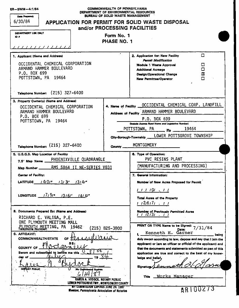
OCCIDENTAL CHEMICAL CORPORATIONARMAND HAMMER BOULEVARDP.O. BOX 699POTTSTOWN, PA 19464
Telephone Number: (215) 327-6400
3. Property Owner(s) (Name and Addrass)OCCIDENTAL CHEMICAL CORPORATIONARMAND HAMMER BOULEVARDP.O. BOX 699POTTSTOWN, PA 19464
Telephone Number: (215) 327-6400
4. Name of Fac
Address of F
2. AppUcation for: New Facility OPermit Modification
Module 1 Waste Approval DAdditional Acreage DDesign/Operational Change SINew Permittee/Operator D
-roty OCCIDENTAL CHEMICAL CORP. LANDFILL. n ARMAND HAMMER BOULEVARD
P.O. BOX 699
POTTSTOWN, PA an 19464CHy-6orough
CAtintv
.Tn«n .P LOWER POTTSGROVE TOWNSHIP
MONTGOMERY M
5. U.S.G.S. Map Location of FacilityT M,r.N.m. PHOENIXVILLE QUADRANGLEM.PNun,h« AMS 58fi4 II NE-SERIES V831Center of Facility:
LATITUDE /4/0/° /1/3/' /3/4/*
LONGITUDE /7/5/« /3/6/' /4/4/'
8. Documents Prepared By: (Name and Address)
RICHARD E. VALIGA, P.E.ONE PLYMOUTH MEETING MALL£$hWMIrE:TING» PA -19462 (215) 825-3800
9. AFFIDAVIT: \ ACOMMONWEALTH/STATE OP ' ClJ j{ JLJfJjOLA~ 0 —
COUNTY OP 7 * WCL ffHfi. LbC *
Sworn and subscribed to bafdra ma th!» ..SL.ijL
'' £A*JL*L^ 711 fcUd-M-JL__• v NCfTMY njtUC „ • U My rniftcniMliJ tipX!
.- 7 Wi£MA.H"YOOCK. NOTARY PUBLIC. . lOWERPOTTS6ROreTWP..MONTGOIIERy COUNTY
6. Type of Operation: ^PVC RESINS PLANT
(MANUFACTURING AND PROCESSING)
7. General Information:
Number 'of New Acres Proposed for Permit
/ / / /O/ . / /
Total Acres of the Property/ /2/6/7/ . / /
Number of Previously Permitted Acres/ / /2/3/ . / /
PRINT OR TYPE Name to be Signed: _ ,_ n /0 .Data: // 31/84
, Kenneth H. Garner h-1duly sworn according to law, depose and say that 1 (am theapplicant) or (am an officer or official of the applicant) and
application are true and correct to the bast of my know-ledge and belief /? j
Thto Worlds Manacrer
. • .- «r uuinissiun IXPIRES JUKE a iss?1 ———————————— 9 o i (^ ft J> > '4 ——. ' «*mbtr. Pinnsyivinii Assodation of Hotiriw Rti I U U £ / w

1.0 INTRODUCTION
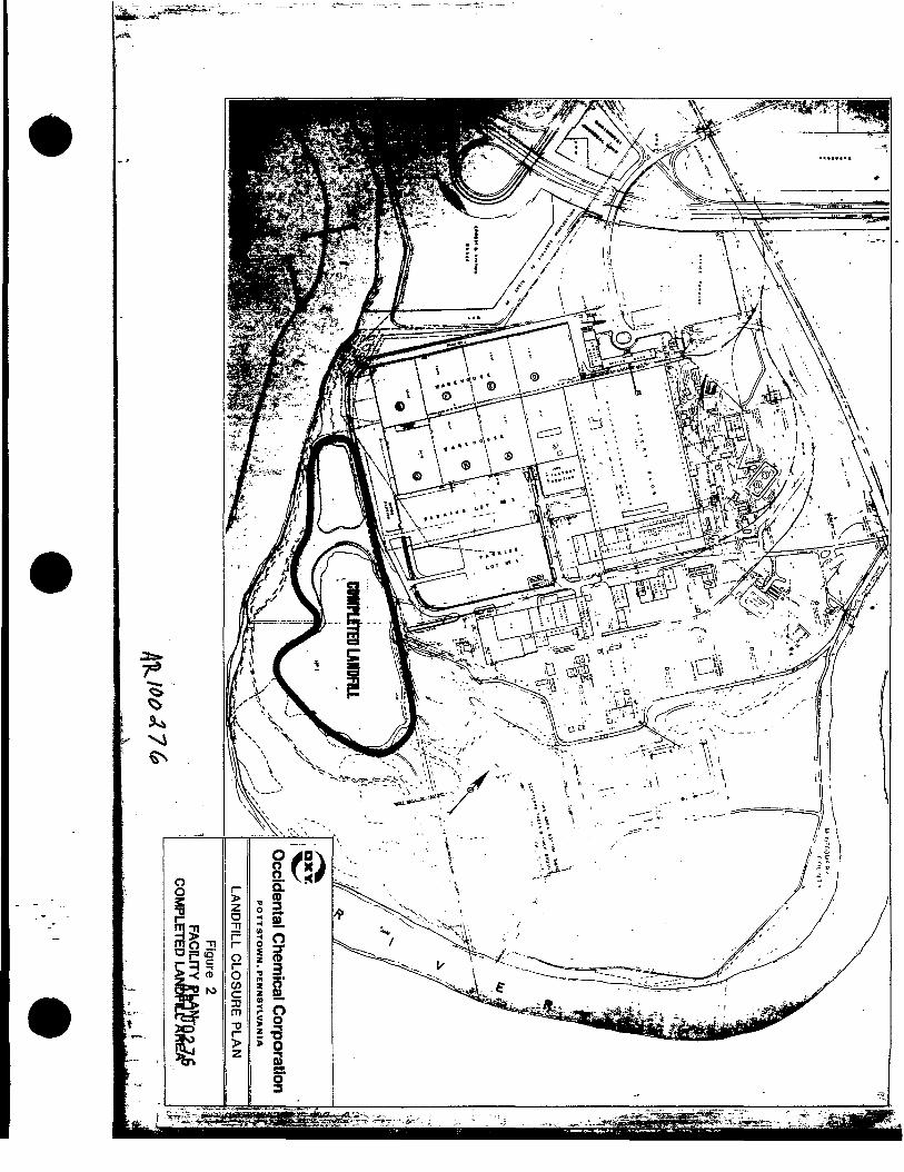
Occidental Chemical Corporation's (Occidental) PVC Resins Division plantis located approximately 3 miles southeast of the Borough of Pottstown inMontgomery County, Pennsylvania. The Schuylkill River forms the western,southern, and eastern boundaries of the plant site (see Figure 1). Thetopography of the site is characteristically flat where the actual manu-facturing facilities are located, then slopes towards the river. Theslope increases along the river bank.
The Occidental site consists of approximately 267 acres, which includes42 acres of manufacturing, office, and outdoor storage areas, and 33 acresof inactive manufacturing/storage building space. Paved parking areas,roadways, and open land comprise the remaining acreage. Two wastewaterlagoons, four inactive sludge-filled earthen lagoons, and two landfillareas (one completed and one active) are located in the western and south-ern portions of the site between the river and the manufacturing areas(see Figures 2 and 3).
Occidental purchased the facility from the Firestone Tire and Rubber Com-pany (Firestone) on December 3. 1980. Firestone operated the Pottstownplant since 1945, originally leasing it and subsequently purchasing itfrom the Defense Plant Corporation.
During the 40 years of active manufacturing at this facility, severaltypes of industrial wastes were generated and disposed onsite in a land-fill adjacent to the existing plant facilities. Fly ash, carbon black,tire plant wastes, wood pallets, paper, cardboard, PVC sludge, and PVCscraps were generated during the Firestone operation. No records existof the wastes produced during previous manufacturing operations. Occi-dental operates only the PVC facility, generating all of the above-men-tioned wastes, with the exception of tire plant waste and carbon black.
Occidental retained BCM Eastern Inc. (BCM) to develop a closure plan andgroundwater monitoring program for the completed landfill area. BCM hasdeveloped this plan in support of Occidental's intent to close the land-fill in accordance with the Pennsylvania Department of Environmental Re-sources (PADER) regulatory requirements.
-1-

BCM Engineers, Planners and Scientists
>"5
oCOO§09
OCCIDENTALCHEMICAL CORP
i«o.,,.i z A ! flft!OOZ75F'aureli LOCATION MAP

'/ : ! V*X--: *-S. ' I "/W lT:\-

BCM
2.0' BACKGROUND AND PREVIOUS LANDFILL PRACTICES
2.1 DESCRIPTION OF LANDFILL
The total area dedicated to landfill is 23 acres and is permitted underPADER Permit No. 300001. The present active portion is approximately 6acres and will continue to be operated by Occidental.
The completed landfill encompasses approximately 17 acres, and was devel-oped in the original sloping area of the western and southern edge of thepresent active landfill. The approximate elevation of the landfill peri-meter, which parallels the river, is 25 to 30 feet above the present riverplain.
Disposal in the completed landfill area ceased around 1978. Since thattime, a thin soil cover has been emplaced and cover vegetation establishedin most areas. No additional wastes have been disposed of in this areasince its completion.
2.2 COMPLETED LANDFILL WASTE DESCRIPTION
The plant site was originally owned by the Defense Plant Corporation andoperated by the Jacobs Aircraft Engine Company. The property was leasedto Firestone in 1945 and subsequently sold to Firestone in April 1950.No landfill operating records are available from the Jacobs AircraftEngine operation, however, it is believed that manufacturing wastes weredisposed in the completed landfill area. It is speculated that thesewastes included metal turnings, engine parts, and other associated manu-facturing and office wastes.
From 1945 until November 1980, Firestone used this landfill for the dis-posal of tire plant and PVC manufacturing wastes. Tire manufacturing be-gan in 1945 and ceased in 1980. PVC manufacturing began in 1947. Thepossibility exists that off-specification raw materials may have beendisposed in the landfill. These waste materials are listed in Appendix 1.No records of wastes deposited in the landfill existed until the 1970s.
Since 1980, Occidental has used the active landfill for the disposal ofPVC manufacturing wastes, PVC sludge, PVC scraps, wood, cardboard, officewastes, and fly ash.
-5-

BCM
2.3 PAPER FACILITY PERMIT HISTORY
The initial application for a permit to operate a solid waste disposalfacility was submitted by Firestone to the Pennsylvania Department ofHealth, Housing, and Environmental Control on April 6, 1970. On August 6,1973, a permit for solid waste disposal was issued by the PADER (PermitNo. 300001). This permit covered all of the completed areas indicated onFigure 2, including the landfill operations performed by the Jacobs Air-craft Engine Company and Firestone.
In 1974, Firestone proposed operating an experimental pilot plant to studythe removal of S02 from oil-fired boilerhouse flue gas. This pilotplant generated calcium sulfite, calcium sulfate, and sodium sulfatewastes. The PADER initially prohibited Firestone from using the existinglandfill for disposal of these wastes. As a result, on December 11, 1974,Firestone applied for a permit to expand the existing permitted landfillto accommodate the new wastes, along with existing wastes. The permit wasgranted on September 1, 1977, and covered the area entitled "active land-fill" on Figure 3, along with an area to the west of the completed land-fill which was used for the disposal of $63 waste products.
On March 13, 1981, an application was filed with the PADER to change thename of the permittee from the Firestone Tire and Rubber Company to HookerChemicals and Plastics Corporation (Hooker). This request was amended byan application submitted on September 3, 1982, to change the permitteefrom Hooker to Occidental. The PADER issued a revised permit on January10, 1983, reflecting the name change of the applicant to Occidental Chem-ical Corporation. This latest permit (No. 300001) still requires that alltechnical features of the former permit be in effect.
-6-
HR100278

BCM
3.0 SITE INVESTIGATION
3.1 COMPLETED LANDFILL AREA SITE VISIT
Site visits to the completed landfill area were made by BCM personnel ontwo separate occasions, mid-June and mid-August 1983. The purpose ofthese visits was to establish existing site conditions at the completedlandfill area. Physical and hydrogeological features were examined alongthe entire perimeter and landfill surface. Monitoring wells were locatedand inspected from the surface. Due to heavy rains that occurred in thespring and early summer, it was decided to undertake two field inspectionsto determine the depth of water in the monitoring wells and the existenceof any leachate seeps.
The following features of the completed landfill were examined:
- Surface water runoff/run-on- Grade and slopes- Soil cover- Vegetation- Erosion-prone areas- Access- Leachate seeps/springs- Condition of observation/monitoring wells- General aesthetics
3.2 SURFACE RUNOFF/RUN-ON
Surface water from two sources - direct precipitation and runoff from ad-jacent, upslope. areas - will affect the surface areas of the completedlandfill. A substantial section of the manufacturing plant area, includ-ing much of the paved parking lot and the large warehouse facility is apotential source of runoff to the completed landfill. Stormwater fromthese areas is for the most part collected and conveyed under the land-fill in one location and around it in a second location. A 27-inch storm-water main is located northwest of landfill area "B" (see Figure 4). The1963 warehouse roof and floor drains, along with a portion of the upperaccess road areas, drain to this outlet, which discharges onto the bankof the Schuylkill River.
-7-
HRIQ0279
BCM BQy stern|nc>Engineers, Planners and Scientists
One Plymouth Meeting • Plymouth Meeting, PA 19462 • Phone: (215) 825-3800
August 2, 1984
Mr. Wayne LynnRegional Solid Waste ManagerDepartment of Environmental Resources1875 New Hope StreetNorristown, PA 19401
Subject: PADER Permit No. 300001Occidental Chemical CorporationArmand Hammer BoulevardPottstown, PA 19464BCM Project No. 00-4064-01
Dear Mr. Lynn:
BCM Eastern Inc. (BCM) was retained by Occidental Chemical Corporation(Occidental) to develop, in accordance with Pennsylvania Department ofEnvironmental Resources Regulations, a ^evised closure plan for the solidwaste landfill located at Occidental's Pottstown facility. •
As this revised closure plan will result in a modification to Occidental'sexisting Solid Waste Disposal Facility Permit (No. 300001), Form No. 1,Phase No. 1 (Application for Permit For Solid Waste Disposal and/or Pro-cessing Facilities) has been completed and is attached to the ClosurePlan.
The landfill was originally operated by Firestone Tire and Rubber Company(Firestone) until Occidental purchased the facility in 1980. During theFirestone operation, wastes from the tire manufacturing and PolyvinylChloride Resins facility were disposed along with fly ash and officewastes. Firestone ceased the tire manufacturing operation in 1980, andfrom the time of purchase until the present, Occidental has operated onlya PVC Resins manufacturing and processing plant.
The revised closure plan reflects a change over the currently approvedplan, in that a 20 mil - PVC liner system will be utilized as a cap,along with additional monitoring wells and different groundwater analysesparameters.
A Member Firm of Betz«Converse»Murdoch»lnc.
ftBiQ0280

BCM
OCCIDENTAL CHEMICAL COMPANY -2- AUGUST 2, 1984
It is acticipated that upon review and approval of the proposed closureplan, Occidental would proceed to implement the plan on the current com-pleted landfill areas in the Spring of 1985.
The enclosed landfill closure plan is hereby submitted for your review.Should you have any questions, please do not hesitate to contact me.
Richard E.Section ManagerResiduals Management Group
/dmdEnclosurecc: J.A. King, Occidental
D.J. Henry, OccidentalG.B. Markert, Firestone


BCM
Most of the drainage from parking lots 3 and 4, all of the roof and floordrains in the 1955 warehouse, and portions of the resin production facil-ity runoff goes to a 60-ifich stormwater main, which is located under thecenter of the landfill in area "A." Since the bulk of the precipitationfalling on the site next to the landfill is diverted under it, the prin-cipal source of surface water on the completed landfill would be directprecipitation.
The present upper surface of the completed landfill is quite flat, withonly a few areas where precipitated water can accumulate and run off.There is evidence of such occurrences along isolated portions of the land-fill, particularly where vehicular traffic has made ruts in the sideslopes.
There appears to be no major problem with erosion on the surface, however,some side slopes will need to be recontoured to obviate potential erosion.
3.3 GRADE AND SLOPES
The majority of the completed landfill surface is very flat (<2 percentslope), with moderately steep (25 to 30 percent) side slopes. In area "B"of the landfill (see Figure 4), located across from the 1955 warehouse,there are side slopes up to 60 percent.Flat areas will maximize percolation of precipitation into the landfill,which is not desirable. Therefore, a re-adjustment of grade will benecessary in many cases to provide proper drainage of precipitation fromthe site surface. Also, a minimum 2-percent grade must be maintained onthe surface area of the landfill, to meet the provisions of the approveddesign plans. Where steep slopes exist, provisions will be made in theclosure design to reduce the slope to within 20 to 30 percent.
3.4 SOIL COVER
The depth of soil cover present on the completed landfill is somewhatvariable, but generally inadequate for proper closure. There are manyplaces where waste materials (tires, PVC fragments, etc.) are exposed atthe surface. On the side slopes, this problem exists to a lesser degree.The side slope of area "B" has a considerable amount of exposed materialas a result of erosion and soil excavation.
It will be necessary to obtain additional soil cover for the completedlandfill to provide the 2-foot depth of soil cover required by PADERregulations and the approved plans for the facility. As discussed in
-9-
HRI00283

BCM
Section 3.2, additional soil will be required to meet the approved per-mitted final contour design elevations. The specific recommendations re-garding additional soil requirements are discussed in the closure planpresented in Section 6.0.
3.5 VEGETATION
The vegetative cover varies considerably over the completed site. The topsurface is seeded annually, but the combination of thin-to-nonexistentsoil cover and exposed waste results in sparse growth and a poor permanentcover.
The side slopes around most of the completed landfill have considerablevegetative growth, including portions covered by well established standsof crown vetch, shrubs, and scattered small trees. In general, the sideslopes are well vegetated.
In area MB," a portion of the fill (approximately 25 feet by 200 feet) atthe' western end of the completed landfill across from the warehouse ischaracterized by extremely steep slopes, little vegetation, and consider-able exposed waste material. The flat portions of area "B" contain sul-fate-bearing sludges mixed with fly ash. Some of these wastes have workedtheir way to the surface in solution, where they evaporated and crystal-lized, or were never covered properly with soil. These small areas (100to 200 square feet) are barren.
3.6 EROSION-PRONE AREAS
The upper surface, or area "A," of the completed landfill is uniformlyflat. Consequently, there is little or no problem with erosion over mostof this area. It is around the periphery slope areas that the greatestpotential for erosion exists (see Figure 5 at the end of this report).Near the western portion of the completed landfill is an access road thatdivides areas "A" and UB." There is evidence of erosion on, and immedi-ately adjacent to, this road.
The steep side slope of area "B," across from the warehouse, also showssigns of erosion, due to the lack of sufficient vegetative cover. Therest of the side slopes around the completed landfill show only slighterosion. The closure plan will require significant contouring/slope ad-justment to meet the final contour elevations, and these potential erosionproblem areas will be properly addressed.
-10-
ARI0028**

3.7 FACILITY ACCESS
Access to the facility is very limited. The completed and active landfillareas are bounded by the plant/warehouse facilities on one side and theSchuylkill River on the remaining sides. A cyclone fence also borders theplant warehouse perimeter to further restrict access. Entry to the land-fill areas is provided only through a gate on the side of the landfillfacing the manufacturing areas.
3.8 LEACHATE SEEPS
Leachate seeps in the completed landfill area have occurred in severallocations on the side slopes and at the base of the fill. The side slopesof the completed landfill were inspected by BCM personnel on two occa-sions, in mid-June and mid-August 1983. Weather conditions preceding thefirst inspection included one of the wettest spring seasons on record,with frequent and heavy precipitation into late May and early June. TheAugust inspection was conducted after more than 1-1/2 months of extremelyhot and dry weather.
3.8.1 Synopsis of June Field Trip Observations on Leachate
No actual flowing leachate seeps were observed, but several areas hadyellow-orange stained soils, marking the presence of seepage zones. Someof these seepage zones (soils) were only slightly wet on the surface.These were not common along the edge of the landfill, but seemed to beassociated with topographic features at the top surface of the landfill,i.e., a shallow depression on the landfill surface was usually accompaniedby a seep or stained soil zone on the side slope or base. Only minorleachate seeps were found, in spite of the heavy spring rains that re-sulted in greater than average rainfall for the first half of the year(more than 11 inches above the average).
The landfill base and side slopes were inspected from an access road whichparallels much of the landfill. Only a few leachate seeps originatingfrom either the base or side slopes were noted. These locations wereidentifiable as landfill leachate seeps, due to the yellow-orange dis-coloration of the soil surface. At no location did the discoloration ex-tend across the access roadway, which is approximately 6 to 8 feet wide.It appeared from the soil stains that the peak leachate flow was not suf-ficient to extend surficially beyond 2 to 4 feet from the base of thelandfill. As there was no evidence of heavy or widespread leachate flow,these leachate seeps appear to have had only a minor impact, if any, onsurface water runoff.
-11-
ARI00285
BCM
3.8.2 Synopsis of August Field Trip and Observations on Leachate
No wet spots or leachate seeps were found in any of the completed land-fill areas examined, including the entire base of the slopes around thecompleted landfill section. The 60-inch stormwater sewer main that flowsbeneath the landfill was inspected. Some staining was observed at theoutfall, however, since this main conveys runoff from the plant site, in-cluding the parking lots, it is difficult to accurately pinpoint thesource. The pipe was totally dry at the time of BCM's inspection. Theoutfall from the pipe had created a small "plunge pool," which was theonly standing water observed on the site. The water was clear, but thebottom sediment had a slight yellowish color. There also was a slightsheen on the water, which was probably due to small amounts of oil residuefrom the parking lot and plant roadway areas.
3.9 GENERAL AESTHETICS
The existing completed landfill soil cover lacks consistency of depth andslope, and is too thin in most areas. There are several locations wherewaste materials such as tires, rubber fragments, and PVC sheeting materialare exposed at the surface. Consequently, the quantity and quality ofvegetation is poor. The side slopes of the main portion of the completedlandfill vary in appearance. In area "B," the upper slopes across fromthe warehouse are excessively steep, and there is considerable exposureof waste materials on these barren slopes.
The lower slopes of area "A" are thinly vegetated, with tires and otherdebris on the surface. This condition decreases the vitality of thevegetative cover, and increases surface water infiltration into the land-fill. Along the side slopes are a few small stands of young trees thatwill need to be removed, since these deep-rooted plants contribute to in-creased surface water infiltration. The side slopes of area "A" areapproximately 30 percent, while the top surface is nearly level.
Much of the remaining land outside of the plant and landfill areas isfloodplain area along the Schuylkill River meander. Between the landfilland the river, most of the upstream portion of this floodplain is heavilywooded with black walnut, oak, sycamore, beech, and wild cherry. Thiswooded area provides an excellent "screen" between the river and the en-tire plant site. On various field inspections in the area, BCM personnelsaw numerous deer tracks and waterfowl.
-12-
HRIG0286

4.0 GROUNDWATER HYDROGEOL06Y, WATER QUALITY, AND MONITORING
4.1 BEDROCK GEOLOGY
The plant site occupies virtually the entire inside portion of a meanderon the Schuylkill River. The geologic units comprising the site are theBrunswick Formation with interbedded Lockatong. These units are sedimen-tary in origin, and eons ago were tilted about 12 to 15 degrees to thenorth-northwest by uplifting processes. Longwill and Wood (1965) describethe units as follows:
Brunswick Formation - red shale and siltstone, with a few sand-stone beds
Lockatong Formation - dark-gray massive argillite and subordinateplaty dark-gray mudstone and black shale
Since both units have poor primary porosity (intergranular openings withinthe rock), groundwater transport is dependent on the secondary porosity(cracks and bedding planes). Weathering of the shale in the upper 200feet of these units typically results in a development of a low-permeabil-ity zone between the surface recharge area and the groundwater pumpingzone below the weathered zone. Consequently, wells properly emplaced inthe Brunswick typically exhibit initial high yield, then drop off incapacity as the readily available water in the deep zone is removed.After that time, the well capacity is dependent on recharge that can seepthrough the low-permeability zone above, plus what moves in laterally atdepth. The anisotropic (nonuniform) nature of the secondary porositylimits the area that can contribute flow to a pumping well.
4.2 SURF 1C IAL MATERIALS
The site surface materials have been substantially altered by constructionactivity at the site since the early 1940's. There has been both cut andfill, thus characterization of soil depths and nature of the materials isdifficult. The prevalence of water-rounded fragments, even in the soilswell above the present floodplain, indicates that the Schuylkill Riveronce flowed at a higher elevation than at present. The Montgomery CountySoil Survey shows a predominance of Raritan soils, or "made-land" fromRaritan soils, which are described in the soil survey as soils derivedfrom old stream sediments or terraces, which may contain as much as 10percent gravel.
-13-
flRI00287

BCMThe lowest elevations adjacent to the river are more recent floodplaindeposits, as evidenced by the coal dust contents. The coal is a resultof upstream mining activity from the mid-1800s to the mid-1900s.
The groundwater flow in the floodplain and terrace deposits is quite dif-ferent than the flow in the, underlying rock units. The floodplain iscomposed of rather permeable sediments, silty sands, and gravels. Thus,the water table is controlled by the level of water in the river.
The terrace deposits on the plant site do not appear to underlie the com-pleted landfill area, except along the inside boundary. The distributionof waste materials at the landfill area indicates that the wastes werebrought to the edge of the terrace deposit and placed over the lowerfloodplain. The level of these wastes gradually extended over the flood-plain to the level of the terrace. An observation well that had beenaugered through the waste material (OW-23) came out into floodplain de-posits at the same elevation as the floodplain adjacent to the landfill.The terrace deposits on the plant site have been extensively reworkedduring construction activity, but can be characterized generally as agravelly clay-loam. The permeability varies considerably over the site,and is proportionate to the clay content. The completed landfill shouldhave no impact on the terrace deposits, since the terrace materials aregenerally all upgradient of the landfill materials.
4.3 EVALUATION OF PREVIOUS STUDIES
The former owner and operator of the plant, Firestone Tire and RubberCompany, had contracted an engineering firm to conduct an investigationinto "the areal extent and chemical nature" of the groundwater potentiallyaffected by the landfill. The conclusions from this investigation werethat a limited zone of affected groundwater existed immediately around thelandfill, that the zone did not appear to be spreading, and that if con-trol were necessary at some future time, it could be accomplished withinthe shallow alluvial groundwater system.
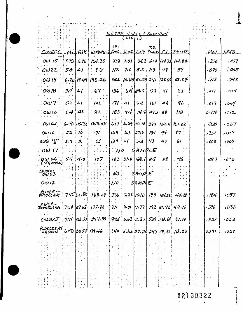
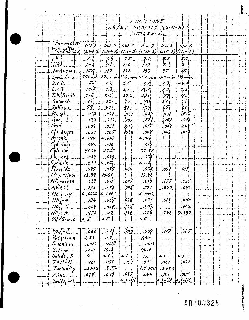
The evaluation presented to the former owner was largely based on a setof water quality samples collected in April 1976, following the installa-tion of several observation wells in March 1976. These data from thePhase I report entitled "Hydrogeologic Analyses of Existing and ProposedLandfill and Sludge Lagoon Sites" prepared for Firestone by Martin andMartin, Inc. are presented in Appendix 3. This datum was reviewed by BCMhydrogeolegists and chemical engineers, and the following alternativedata evaluation and conclusions were developed.
-14-

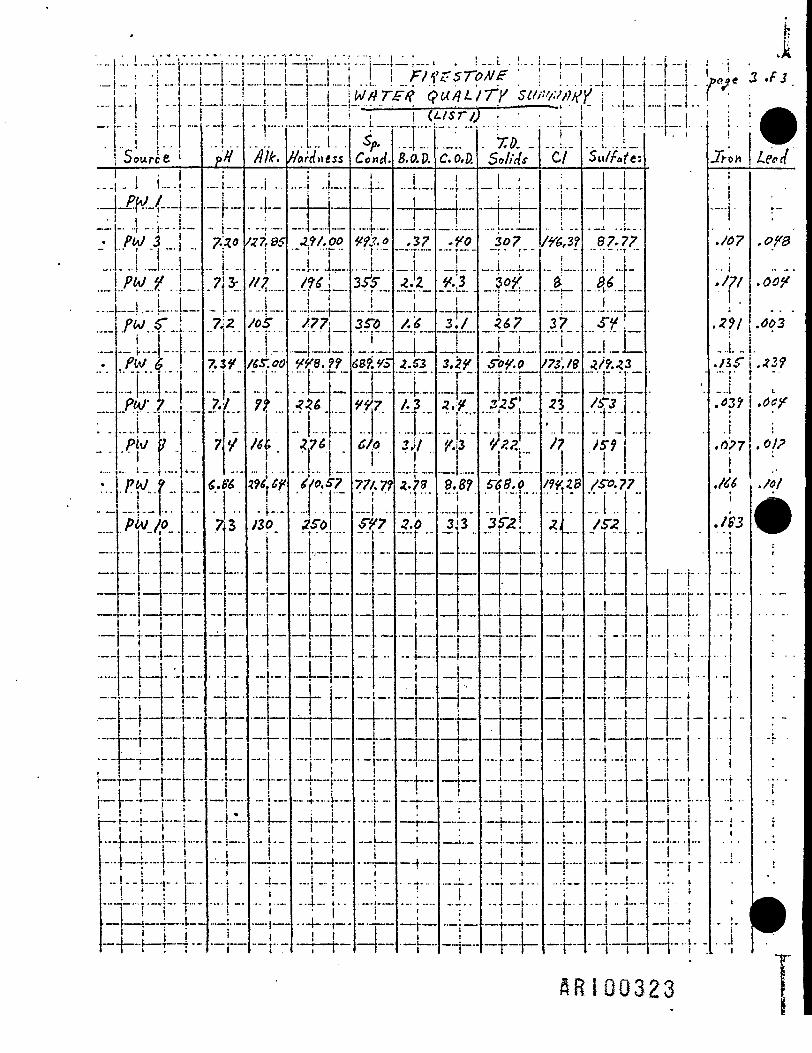
The datum was grouped according to location with respect to the landfilland depth, providing seven shallow wells immediately adjacent to the land-fill; two a short distance into the floodplain; two deeper, so-called rockwells; two process water wells (deep) situated close to the landfill; andfour process water wells (deep) located away from the landfill (see Figure6). Samples of Schuylkill River water also were collected and analyzedat that time. The analyses that were performed included pH, alkalinity,hardness, specific conductance, biochemical oxygen demand (BOD), chemicaloxygen demand (COD), total dissolved solids (TDS), chloride, sulfate,iron, and lead.
The most useful chemical analyses are specific conductance, COD, and TDS.With only one exception, all the BOD data are less than 10 mg/1, anddrawing valid inferences as to cause-and-effect using this parameter atthose low levels is impossible. Much of the other data appear to be quitescattered, with little on which to base solid, supportable cause-and-effect relationships. The deeper wells (observation rock wells and pro-cess wells) show a statistical correlation coefficient (R<?) of 0.79 be-tween sulfate and specific conductance. When the shallow wells are in-cluded, however, the R^ drops to 0.285. The deep wells show a higheraverage sulfate concentration than the shallow wells.
The mean and standard deviation (N-l) of the deeper wells (10 samples) are131 and 50 mg/1 of sulfate, respectively, while the shallow wells (8 sam-ples) show 75 and 20 ppm of sulfate, respectively. River samples takenon that same day contained 44 parts per million (ppm) of sulfate upstreamof the site and 49 ppm downstream. These results are considered equal,with the difference attributed to variability in sampling and analyticalmethods. The process wells located closest to the completed landfill,PW-9, 6, and 8, exhibited the highest sulfate levels (151, 219, and 159ppm, respectively).
It appears that the landfill is situated on a portion of the potentialrecharge area of the water being pumped from the process wells. However,the zone of reduced permeability that occurs between the surface and thepumping zone of the process wells allows only a portion of the groundwaterthat has passed through the landfill to reach the pumping zone. The re-mainder of the groundwater will remain in the permeable floodplain de-posits. The movement of the near-surface water in the floodplain obvi-ously is tied closely to the level of the Schuylkill River, such that thedirection of groundwater flow will alternate to and from the landfill.
The shallow observation wells, located close to the landfill, indicateminor and episodic groundwater impact from the landfill. This likely isdue to a combination of events, including:
-15-
HRIOG289

C z SL "i* Ji -^ VJ • oo >
"" I 5 is° r|3i n|l§ ^ISs-& > X °|2m O uO i Oar-E 3 5Sm5 ™ _Cn O=rd O=>m o H _. r-Z rj « >z>z >2z2 o o <r"ffl 2 -<®zo -taaO m 0313
="• ;2 5 2S 5 22 S? zP

1. Dilution of any chemical constituents
2. Low production and release of soluble constituents from thelandfill due to its position above the water table
3. Drawdown of groundwater from the landfill by process wellpumping
The facility's current Pennsylvania Solid Waste Disposal Permit (No.30001) states that the "process wells will continue in operation to pro-vide the necessary groundwater withdrawal in order to manipulate the watertable in a manner that precludes escape of pollutants at all times." Thisstipulation is based on a belief that the groundwater passing through thelandfill, and presumably dissolving soluble constituents during that pas-sage, is pulled into the deep water supply zone of the bedrock by thedrawdown of the pumping process wells. The validity of this assumptionis doubtful, due to the presence of the low permeability zone in the bed-rock, and the high permeability of the floodplain materials.
It is more likely that the nature of the materials disposed in the land-fill have resulted in rapid through-flow of precipitation, and a low rateof leachate production. Dilution in the floodplain deposits probablyfurther diminishes the concentration of any constituents which are ex-tracted from the landfill by infiltrating precipitation. The fraction ofgroundwater in the floodplain deposits that is induced to flow through thelow permeability zone to the process well pumping zone is unknown, but ispresumed to be minimal.
4-4 EVALUATION OF EXISTING MONITORING WELLS
Well data provided by Occidental were compiled and examined to determinethe suitability of the existing monitoring well system at the completedlandfill site, namely, wells OW 1, 2, 5, 6, 9 through 15, 23, and 24(refer to Figure 6). The evaluation of these wells was based on two par-ameters - water level measurement and water quality monitoring.
V4.4.1 Rock Wells
Observation wells 1 and 2 were drilled to depths greater than 115 feetfrom the surface. Wells were cased from the surface to depths of 30 to45 feet, and are open or uncased rock holes below. The depth of standingwater in the wells range from 95 to 110 feet. Thus, they are suitablefor the intended purpose, which is to provde an indication of the waterquality in the deeper portions of the aquifer. The absolute elevation ofthe bottom of the holes (mean sea level (msl)), is 0 feet for OW-2 and
-17-
fiR!0029

BCM
+18 feet for OW-1. By way of comparison, the pump settings of the processwater and potable water wells are at depths ranging from -73 feet to -195feet msl. Thus, the rock wells are not sampling water from the same zonefrom which the pumping wells draw. Since the purpose of the open rockwell is to monitor the presence of chemicals potentially released from thelandfill, the open-hole construction, which has no casing except in theupper part of the hole, provides an adequate integrated composite of thezone in which the hole is open.
4.4.2 Shallow Wells
Observation wells 5 through 26 were installed in March 1976, to permit themonitoring of the shallow water zone around the periphery of the landfillsite. The wells were installed by means of a hollow-stem auger. Theauger drilled holes through the overburden, and approximately 6 to 12inches into bedrock. The wells were constructed of either 2-inch or1-1/4-inch PVC casing and screen. Fine gravel was poured in the annularspace between the screen and augered hole. The remainder of the annularspace was filled in above the screen with clay, concrete, and cuttings.A protective steel locking cap was installed over the PVC casing.
An evaluation of the usefulness of OW-5 through 26 (11 total shallow wellsin the completed landfill area) was performed using the data on waterlevels collected in 1982, and field-checking done in 1983. The depth ofstanding water in the well and four categories of usefulness were deter-mined, as follows:
1. Acceptable - 4 feet or more of water depth2. Marginal - 2 to 4 feet, varying by season3. Poor - 0 to 4 feet, varying with season4. Unacceptable - 0 to 2 feet, all seasons low
Based on these criteria, there are six acceptable, one marginal, threepoor, and one unacceptable. The problems with the four poor-to-unaccept-able wells appear to be derived from the method of installation, whichnecessitated stopping at bedrock. Apparently, there was a high watertable over much of the site in March 1976, which showed a zone of satura-tion at higher elevations than is usually found during the drier seasons.This is quite typical of the soils formed on the type of bedrock geologyat this site.
The result is that during part or all of the year, four of the shallowobservation wells are incapable of monitoring the shallow water tablezone. With the noted exceptions, most of the shallow wells which coverthe completed landfill area are in the acceptable category.
-18-

The two most important problem wells are OW-23 and OW-24. Well OW-23 wasinstalled through the landfill to a depth of 37 feet below the surface.The surveyed elevation of the top casing was 161.87 feet msl, thus thebottom of the hole is at approximately 125 feet. Recently constructedtopographic maps show the floodplain elevation to be 125 (+5) feet. Sincethe completed landfill was put on the floodplain, OW-23 was installed intothe underlying floodplain deposits. The well log on OW-23 reports thatfine sand, silt, and some roots were encountered.
The lack of water in OW-23 precludes sampling to ascertain water quality.However, the fact that there is no water at the depth of the landfillbottom is important knowledge in itself, indicating that the landfill isnot saturated and that the potential for leachate production is conse-quently greatly diminished.
Observation well OW-24, is located on the river floodplain, and is thewesternmost well monitored for the completed landfill, and as such, is animportant data point for a continuing monitoring program. The problem isthat only 1 foot or less of water is found in the well during dry seasons,making collection of representative water samples difficult. Removal ofthree volumes of water is probably insufficient given the depth, and wait-ing for water levels to recover would take too much time.
4.5 MONITORING WELL RECOMMENDATIONS FOR THE COMPLETED LANDFILL
4.5.1 Monitoring Well Locations
There are more wells present in the completed landfill area than arenecessary to properly monitor the landfill. BCM recommends that the fol-lowing existing wells be retained on any future schedule of groundwaterquality monitoring:
- Rock well OW-1 and well OW-12- Well OW-25- Rock well OW-2 and well OW-9- Well OW-24 (to be replaced)- Well OW-27 (new upgradient well to be drilled)- Well OW-6*- Well OW-14* (damaged well; to be redrilled
*Also included in active site monitoring program
Wells OW-1 and 12 and OW-2 and 9 are together because they are "couplets,"i.e., wells drilled immediately adjacent to each other, but sampling dif-ferent depths. Wells OW-25 and 6 are shallow wells that monitor portionsof the landfill perimeter (see Figure 6).
-19-
BCM
In addition to the existing wells discussed above, three additional wellsshould be located in the upper saturated zone under the landfill, to en-able sampling . This includes the northeasterly (OW-14A) and the north-westerly (OW-24A) perimeter locations. Also, monitoring of the shallowwater zone in the extreme upstream (northwesterly) portion of the property(OW-27) is necessary to develop a clear upgradient sampling point. BCMbelieves that these three additional monitoring wells should suffice tocomplete a comprehensive monitoring program. Two would be replacementwells to OW-24 and OW-14, drilled to a depth of 30 to 35 feet. The thirdwould be an a new well near the northwestern edge of the completed land-fill area "B" (OW-27), drilled at least 10 feet into the saturated zonebelow the water table (50 to 60 feet) (see Figure 6).
This would result in nine monitoring wells at the completed landfill site.However, wells OW-14 and OW-6 would actually be monitored as part of the"active landfill" monitoring program. Data from OW-14 and OW-6 would beincluded in submission to the PADER regarding the "completed landfill"area monitoring program.
Although the present landfill permit (copy contained in Appendix 2) re-quires monitoring of OW-5, 6, 7, and 8, this requirement should be modi-fied as follows:
- Well OW-25 monitors essentially the same general areas asOW-5, therefore, OW-25 is preferred
- Well OW-6 is recommended for continued monitoring for boththe closed and active landfill areas
- Well OW-7 is recommended for monitoring the active landfillarea, as discussed in Section 4.6.
- Well OW-8 is a shallow monitoring well; however, it does notmonitor the water quality of the landfill, since it is locatedin the northeastern corner of the property approximately 1,000feet from the active landfill area, and approximately 1,800feet from the completed landfill area. According to the PADERregulation, Chapter 75.38, (b)(7)(i), General Standards forIndustrial and Hazardous Waste Disposal Sites," monitoringpoints shall not be located in excess of 500 feet of the per-mitted area."
4.5.2 Monitoring Well Sampling Frequency and Analysis Parameters - Com-pleted Landfi 1T
The recommended sampling frequency of the monitoring wells for the com-pleted landfill area is once per year, since past quarterly and annualanalyses have not indicated any reason to maintain greater sampling fre-quency. This sampling should begin after the closure of the landfill areais completed.
-20-
RR10029U

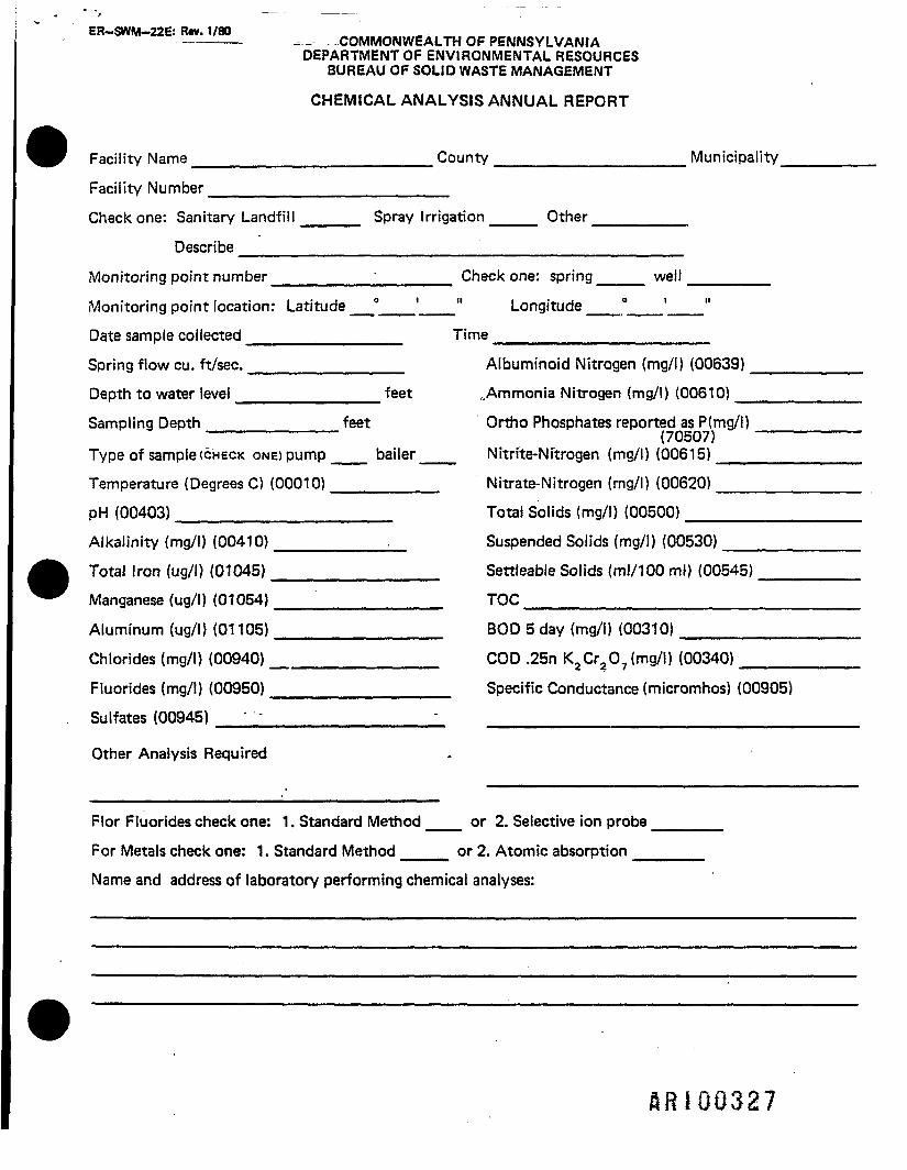
Parameters to be analyzed in the annual sampling program for the completedlandfill are listed in Table 1. Although these parameters differ from thepresent PADER annual chemical analysis requirements (see Appendix 4), theymore adequately reflect the parameters of potential input from depositedwastes. This is substantiated from previous years of monitoring for thefollowing parameters:
- Manganese- Aluminum- Fluorides- Albuminoid nitrogen- Ammonia nitrogen- Orthophosphates- Nitrite-nitrogen- Suspended solids- Settleable solids
Therefore, it is recommended that these nine parameters not be includedin the annual analysis of the completed landfill.
4.6 MONITORING WELL RECOMMENDATIONS FOR THE ACTIVE LANDFILL
4.6.1 Mon i torIng We!1 Locations
To adequately monitor the active landfill area, the following existingmonitoring wells are recommended:
- OW-19- OW-7- OW-22- Rock well - OW-3- OW-14- OW-6
It appears that all of these existing wells are in adequate condition andin the proper location to provide the desired level of monitoring (seeFigure 6). A possible exception is monitoring well OW-19, which had arange of 2.5 to 5 feet of static water in measurements taken during 1981and 1982. This is a marginally acceptable well, and any sustained staticwater levels below 3 feet would warrant its replacement.
Monitoring well OW-14 is recommended for relocation/replacement, due tothe inability to obtain samples year round. Wells OW-14 and OW-6 are alsoincluded in the monitoring program for the completed landfill, as previ-ously discussed.
-21-

TABLE 1
PARAMETERS FOR ANALYSISANNUAL WELL SAMPLING PROGRAM
COMPLETED LANDFILL
PRIMARY DRINKING WATER STANDARDS
BariumCadmi urnHexavalent chromiumMercuryLeadSeleniumSilver
SECONDARY DRINKING WATER STANDARDS
PHTotal ironSulfatesTotal dissolved solidsChloridesZincManganese
DUE TO LANDFILL CONSTITUENTS
NickelTrivalent chromium •NitratesAlkalinityBOD (Biochemical oxygen demand)COD (Chemical oxygen demand)TOC (Total organic carbon)Specific conductanceTemperaturePhenolTOX (Total organic halogens)VoA (if TOX 50 ug/1 or more)TrichloroethyleneVinyl chloride monomerTrans-l,2-dichloroethylene
-22-
SRI00296
BCM
4.6.2 Monitoring Well Sampling Frequency and Analysis Parameters - ActiveLandfill
The recommended sampling and analysis frequency of these wells is quart-erly, with analysis of an expanded parameters list annually. The para-meters for the quarterly analysis required by the PADER are as follows(see Appendix 4):
- pH- Alkalinity- Total iron- Sufates- Total solids- Chlorides- BOD (Biochemical oxygen demand)- COD (Chemical oxygen demand)- Specific conductance
Occidental is proposing that temperature (recorded in field), totalorganic carbon (TOC), and total organic halogens (TOX), will also beanalyzed as part of the quarterly sampling program. Table 2 details thefinal listing of parameters for quarterly analysis.
For the annual sampling program, the PADER requires that 21 parameters beanalyzed (see Appendix 4). The list includes the nine parameters listedfor the quarterly analysis, as well as the following:
- Temperature- Manganese- Aluminum- Fluorides- Albuminoid nitrogen- Ammonia nitrogen- Orthophosphates- Nitrite-nitrogen- Suspended solids- Settleable solids- Total organic carbon- Nitrate nitrogen
As previously discussed in Section 4.5.2, the parameters of manganese,aluminum, fluorides, albuminoid nitrogen, ammonia nitrogen, orthophos-phates, nitrite-nitrogen, suspended solids, and settleable solids are in-appropriate parameters for the wastes being deposited. It is recommendedthat these parameters not be analyzed for the annual analysis program.The following parameters listed in Table 3 are recommended as the annualchemical analysis reporting requirement.
-23-ftRIGQ297

BCM
TABLE 2
PARAMETERS FOR ANALYSISQUARTERLY WELL SAMPLING PROGRAM
ACTIVE LANDFILL
SECONDARY DRINKING WATER STANDARDS
PHTotal ironSulfatesChlorides
DUE TO LANDFILL CONSTITUENTS
AlkalinityTotal sol idsBOD (Biochemical oxygen demand)COD (Chemical oxygen demand)Specific conductanceTemperatureTOC (Total organic carbon)TOX (Total organic halogens)
-24-

TABLE 3
PARAMETERS FOR ANALYSESANNUAL WELL SAMPLING PROGRAM
ACTIVE LANDFILL
PRIMARY DRINKING HATER STANDARDS
BariumCadmiumHex aval en t chromiumMercuryLeadSelenium
SECONDARY DRINKING WATER STANDARDS
PHTotal ironSulfatesTotal dissolved solidsChloridesZinc
DUE TO LANDFILL CONSTITUENTS
Trivalent chromiumSod i urnNitratesAlkalinityBODCODTOC (Total organic carbon)Specific conductanceTemperaturePhenolTOX (Total organic halogens)VoA (if TOX 50 ug/1 or more)TrichloroethyleneVinyl chloride monomerTrans dichloroethylene
-25-
BCM
5.0 LANDFILL CLOSURE PLAN ALTERNATIVES
5.1 LANDFILL CLOSURE REQUIREMENTS
Closure requirements for a completed industrial waste landfill facilitywill vary, due to specific site conditions. Minimum closure requirementsfor the completed Occidental landfill area are set forth in the engineer-ing design plans submitted to the PADER under the existing permit. Theseapproved plans set forth a maximum slope requirement for the surface andsides of the landfill, and are incorporated into this closure plan. Inaddition, a final minimum soil cover of 2 feet over the wastes is speci-fied.
The present permit requirement of groundwater pumping and treatment ofplant process (deep) wells to influence the groundwater table near thelandfill, in order to control migration of potential pollutants, signifi-cantly influences the technical methodology of closure. As previouslydiscussed in Sections 4.1, 4.2, and 4.3, it is believed that the plantprocess deep wells have virtually no influence on any potential pollutantsemanating from the landfill area. Should the landfill monitoring wellsdetect shallow groundwater degradation, a much more appropriate responsewould be to use wells located much closer to the landfill site (seeAppendix 5).
Since it has been established that the bottom of the landfill is notwithin the saturated groundwater zone, the potential impact of the land-fill on groundwater is due primarily to surface water infiltration. As aresult, two primary factors become important:
1. Maintaining sufficient slope to convey precipitation orother surface waters off the landfill surface as quickly aspossible.
2. Preventing infiltration of surface waters by installing animpermeable barrier above the surface of the waste materi-als.
This will further ensure that infiltration will not ultimately form leach-ate, which could enter the groundwater system.
With reference to the field investigations previously discussed, theexisting completed landfill area is deficient in the following featureswhich are necessary for closure:
-26-

BCM
1. Sufficient grade to provide a 2-percent slope over the en-tire existing completed area
2. Lack of a uniform 2-foot final soil cover layer
3. Lack of sufficient side slope maintenance to control erosion
4. Lack of a uniform vegetative cover5. Lack of an impervious barrier above the surface of the waste
to prevent surface water infiltrationTaking these factors into account, a closure plan was developed. The con-cept for the plan was based on utilizing the existing contours of thelandfill surface and minimizing the amount of infiltrating water.
5.2 FINAL CLOSURE PLAN DETAILS
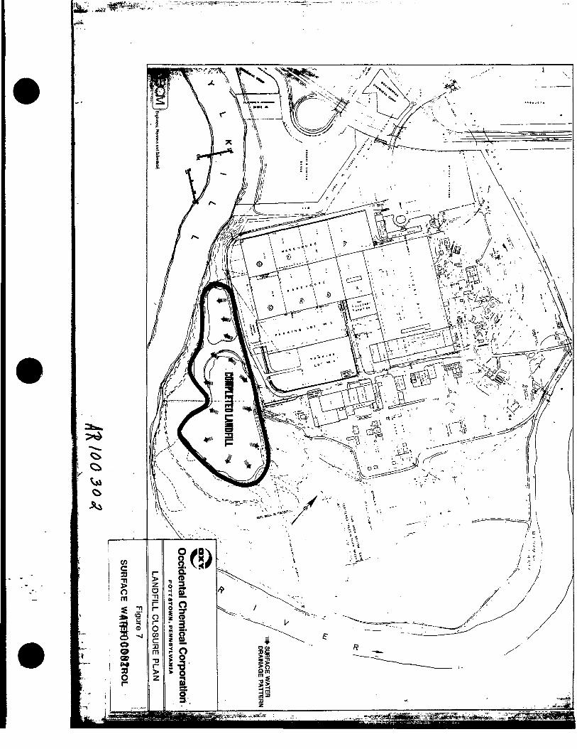
Following BCM's recommendation, Occidental has chosen to use an impervioussynthetic liner system. On the completed landfill top surface, the exist-ing contours will be used to direct surface runoff water towards the sideslopes of the fill (see Figure 7). Soil obtained from offsite sourceswill be used to provide a 2-percent slope over the landfill surface (seeFigure 8). In areas of small depressions, 6 to 24 inches of soil may berequired to obtain the required slope (see Figure 9 at end of report).In other areas, the existing soil cover will be sufficient. The soil usedfor this operation will be classified as clean fill, and will contain nolarge rocks or coarse fragments. This is to prevent potential tearing ofthe PVC material which will be placed over the soil cover.
Following the establishment of the desired slope, a 20-mil-thick PVC linerwill be placed over the entire top surface of the landfill (refer toFigure 10). The PVC liner will essentially prevent the movement of sur-face water into the landfill. The liner material can be manufactured insheets as large as 100 by 400 feet. It is recommended that Occidental buyfrom a PVC manufacturer, which also provides installation services, to en-sure proper placement of the liner. The liner sheets should be bondedtogether by chemical sealant to prevent water infiltration between theliner sheets.
After the liner is installed, a porous soil material layer will be placeddirectly on top of the liner. This will provide a discharge route to theside slopes for water which percolates through the surficial soil cover.The depth of this layer will be determined by the permeability of thematerial used.
-27-


11k«"•1. d• •ss6O
1I• NM
"3CO
?1O
?!I?01 (0
LU
CO
0
<DatOCOO£+-0
1To
1ou0u
/-k
nxv.^ Occidental C
FOTT
tT
z
iCO3o_l_l\L.o<u

BCM
The final soil cover will then be placed over the permeable materiallayer. The depth of this soil layer will be at least 6 inches, to allowvegetative growth. Section 75.24 of the Pennsylvania Solid Waste Regula-tions stipulates the final cover material as follows:
"Final cover shall be soils that fall within the United StatesDepartment of Agriculture (USDA) textural classes of sandy loam,loam, sandy clay loam, silty clay loam, and silt loam. All otherfinal cover materials must be approved by the Department. Thesoil must compact well, not crack excessively when dry, and sup-port a vegetative cover. The coarse fragment content, particlesnot passing the No. 10 mesh sieve (2 mm), shall not exceed 60percent by volume."
A seedbed will be prepared after the soil cover is emplaced and finalgrading has been completed. A recommended perennial seed mixture, con-sisting mainly of grasses, fescues, and wildflowers will be obtained fromthe Montgomery County Soil Conservation Service and submitted to the PADERfor final approval before application. Liming and fertilization recom-mendations also will be followed.
The PADER requirement of 2 feet of soil cover to "cap" the landfill willbe achieved by the above-outlined plan. The depth of each layer will beas follows:
Layer 1 - Contouring soil cover 6 to 24 inchesLayer 2 - 20-mil PVC liner systemLayer 3 - Permeable material 6 to 12 inchesLayer 3 - Final soil cover 6 to 12 inches
Due to the slope of the sidewalls of the landfill, water will move at amuch higher rate than will water on the top surface of the landfill.Therefore, infiltration of significant amounts of precipitation into theside slopes is not a major concern. For this reason, PVC liner materialwill not be emplaced over the landfill side slopes. Also, the linerplaced on the side slopes could contribute to instability of the overlyingcover soil. Thus, the proposed closure plan for the landfill sidewallswill consist only of the removal of small trees and bushes, the recontour-ing of any swales or runoff depressions, and the placement of approxi-mately 12 to 24 inches of soil cover, there is an average of 6 to 12inches of soil cover presently on the landfill sidewalls.In the northwest corner of the landfill across from the warehouse, wherethe slope of the sidewall exceeds the maximum 3:1 ratio, a terrace-typegrading plan will be implemented. One terrace, approximately 10 feet
-31-

wide with a 1-percent slope, will be constructed midway up the sidewall.Additional soil cover will be necessary to meet the 30-percent slopeallowance. By terracing steep sidewalls, the amount of fill material re-quired can be decreased. Final grading and seeding of the sidewalls willbe done in a similar manner, as on the top surface of the landfill.
5.3 LANDFILL CLOSURE WORK SCHEDULE
Table 4 details the projected work schedule and estimated time requirementfor the previously detailed closure plan. Assuming the closure plan issubmitted to the PADER in August 1984, final closure approval should begranted by January 15, 1985. Final bid specifications and documents wouldthen be prepared, and contracts should be secured by March 15, 1985.Thus, actual closure activities could commence on April 1, 1985, andweather permitting, would be completed in early October 1985.
-32-
U R IO

BCM
TABLE 4
LANDFILL CLOSURE PLANPROJECTED WORK SCHEDULE
EstimatecTask DuratJ
Work/Task Description (Weeks)
Submit final closure plan to PADERand obtain comments 15
Receive PADER comments and prepareresponses 2
Obtain PADER approval 6
Prepare final bid specifications 4
Obtain bids and contracturalagreements 4
Initiate closure actives (clearing,fill and grading, liner installation,final soil cover emplacement andgrading, seeding) 26
i Estimated Scheduleion (Month)
Initiate
Aug. 2, 1984
Nov. 15
Dec. 1
Jan. 15
Feb. 15
April
Complete
Nov. 15, 1984
Dec. 1
Jan. 15, 1985
Feb. 15
March 15
Oct. 1
-33-
HRI00307
BCM
APPENDIX 1
TYPICAL ITEMS CONTAINED IN THE LANDFILL
ft! 19!

TYPICAL ITEMS CONTAINED IN THE LANDFILL
Tire - inert rubber
Friction fabric - fabric impregnated with rubber - inert cloth and rubber
Refiner waste - material screened from rubber -inert rubber
Bladders and bladder scrap - inert rubber
Bags, paper, from pigments
Flashing - inert rubber
Carbon black - inert, fine carbon
Rags, cleanup, from machinery - inert fabric, possibly oily, carbon black
Polyethylene - inert
Boxes, wood paste board - paper - paper cups inert
Polyvinyl chloride film or granular - inert polymer
Cans, miscellaneous - inert
Tire buffing - inert
Miscellaneous compounding agents or dust connected with cleanup or bags orspills. Includes sulfur, zinc oxide. All water-insoluble. Inert aslong as handled properly.
Starch, clay, talc - inert BOD
Synthetic polymer fabrics - inert
Fly ash - from boilers - inert
Lagoon waste - calcium carbonate, calcium hydroxide, resins, rubber - somesoluble material in resin waste, such as methocel, emulsifier, wettingagent, all small quantities
Pallets, wood - inert
Oil/water emulsions
S02 sludgeButadiene styrene latex coagulum
Wastewater treatment sludge
Floor and roadway sweepings
Metal banding and strappings
Fiber drums - inert
BCM
APPENDIX 2
PADER PERMITS ISSUED
A R I 0 0 3 1 i
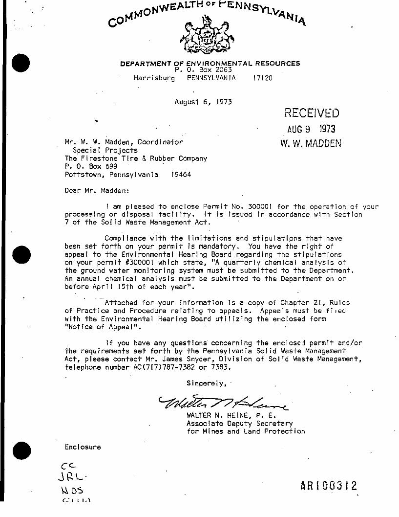
DEPARTMENT OF ENVIRONMENTAL RESOURCESP. 0. Box 2063
Harrisburg PENNSYLVANIA 1 7120
August 6, 1973RECEIVED
• . AUG9 1973Mr. W. W. Madden, Coordinator W. W. MADDEN
Special ProjectsThe Firestone Tire & Rubber CompanyP. 0. Box 699Pottstown, Pennsylvania 19464
Dear Mr. Madden:
I am pleased to enclose Permit No. 300001 for the operation of yourprocessing or disposal facility. It is issued in accordance with Section7 of the Solid Waste Management Act.
Compliance with the limitations and stipulations that havebeen set forth on your permit is mandatory. You have the right ofappeal to the Environmental Hearing Board regarding the stipulationson your permit #300001 which state, "A quarterly chemical analysis ofthe ground water monitoring system must be submitted to the Department.An annual chemical analysis must be submitted to the Department on orbefore April I5th of each year".
Attached for your information is a copy of Chapter 21, Rulesof Practice and Procedure relating to appeals. Appeals must be fiiedwith the Environmental Hearing Board utilizing the enclosed form"Notice of Appeal".
If you have any questions concerning the enclosed permit and/orthe requirements set forth by the Pennsylvania Solid Waste ManagementAct, please contact Mr. James Snyder, Division of Solid Waste Management,telephone number AC (717)787-7382 or 7383.
Sincerely,
WALTER N. HEINE, P. E.Associate Deputy Secretaryfor Mines and Land Protection
Enclosure
AR I 003 I 2c..: 11 i . \

DEPARTMENT Ot- HUS*1/J<»1A l_l I V I I Wi imwi i I u i
Land Protection^PERMIT
FOR
SOLID Y/ASTE DISPOSAL AND/OR PROCESSING FACILITYNo. 300001
Under the provisions of Act241,The Pennsylvania Solid Waste Management Act.a permitfor a solid
waste dfsposal and/or processing facility located at (Municipality Lower________Pottsgrove Township____jn fte county of ____Montgomery___________
is granted to (applicant) The Flrestone Tire & Rubber Company____________
(address) P. 0. Box 699, Pottstown. Pennsylvania 19464____:____
this permit is applicable to the facility named as Firestone Landfill___________
.and described as:Firestone LandfiI I
Latitude 40° 07' 05|: NLongitude 75° 30' 00!: W
This permit will expire _____ ———______________ ; however, it isEnvironmental Resources
subject to prior revocation or suspension by the Secretary of HsaJiWor any violation of the law under
which it is issued or for any violation of the rules and regulations authorized thereunder or for non-
compliance of any stipulations or limitations listed below.
A quarterly chemical analysis of the ground water monitoring systemmust be submitted to the Department.
An annual chemical analysis must be submitted to the Department on orbefore April 15th of each year.
DATE ISSUEDAssociate Deputy Secretary for Mines and Land
THIS PERMIT IS NON-TRANSFERABLE ProtectionDepartment of CnvironrnnntnI Rc-sourra |' |
rv\ i «-\

-...*-«,««v. t/,4 COMMONWEALTH OF PENNSYLVANIADEPARTMENT OF ENVIRONMENTAL RESOURCES
BUREAU OF LAND PROTECTIONPermitFor
Solid Waste Disposal and/or Processing Facility
Permit No. J00001 ^ ,__Date Issued ""$"£? 1 197TDate Expired ___________
Under the provisions of Act 241, The Pennsylvania Solid Waste Management Act, P.L. #788,a permit for a solid waste disposal and/or processing facility at (municipality) Lower___
Potts grove Township______ in the County of ____Montgomery______is granted to (applicant) Firestone Tire & Rubber'Company_____________(address) ________ P. 0. Box 699__________________________
_____Pottstown, Pennsylvania 19464_____________This permit is applicable to the facility named as Fires'tone ..Landfill__________________________________________ and described as:
FIRESTONE LANDFILL(expansion)
Latitude 40° 13' 34" NLongitude 75° 36' 44" W
This permit is subject to modification, amendment and supplement by the Departmentof Environmental Resources and is further subject to revocation or suspension by theDepartment of Environmental Resources for any violation of the applicable laws or the rulesand regulations adopted thereunder, for failure to comply in whole or in part with theconditions of this permit and the provisions set forth in the application no. 300001____which is made a part hereof, or for causing any condition inimical to the public health,safety or welfare.
7\ A f A /?>d
FOR THE DEPARTMENT OFENVIRONMENTAL RESOURCES
THIS PERMIT IS NON-TRANSFERABLEPage _L_ of _1_ '

»LP-aj,i«Ev. t/74 COMMONWEALTH OF PENNSYLVANIADEPARTMENT OF ENVIRONMENTAL RESOURCES
BUREAU OF LAND PROTECTIONPermitFor
Solid Waste Disposal and/or Processing Facility
Permit No. 300001Date Issued SFP 1 1Q77Hato Pvnirorl *'*•>/ IDate Expired
1. This permit is granted to Firestone Tire & Rubber Company for the operationof an industrial solid waste disposal facility in accordance with the appli-cation dated December 12, 1974, operational plans, design plans and othersupporting data submitted in September, 1975, October, 1975, January, 1977and Apr.il, 1977. This permit is for additional acreage and is a supplementto Permit No. 300001 issued in August, 1973.
2. The existing previously permitted landfill area shall be covered, gradedand seeded as per Firestone's original solid waste disposal site plans.
3. Monitoring Wells #5, #6, #8 and 120 shall continue to be monitored on aquarterly and annual basis with the chemical analyses submitted to the
• Department within the presently established reporting periods.. •.
4. Within sixty (60) days of the date of this permit, Firestone shall providethe Department with a statement insuring that the process wells will con-tinue in operation to provide the necessary ground water withdrawal inorder to manipulate the water table in a manner that precludes escape ofpollutants at all times. In addition, this statement must provide assuranceto the Department that any pollutants withdrawn from the process wells beproperly treated, discharged or disposed of, as per Department standards.The statement must be signed by a responsible official of the company andalso bear the company's official seal.
If the above-referenced statement cannot be provided, Firestone must ex-pedite detailed design and implementation of alternate leachate collectionand treatment systems as proposed in pages 12 .to 14 of the Martin & MartinReport, dated September, 1975, revised October, 1975. Design and imple-mentation schedule must be approved by the Department.
5. If routine well monitoring shows a trend of increasing degradation ofwater quality, Firestone'will be responsible for implementing alternativeReport C0llect1on and treatment systems as proposed in the Martin 4 Martin
THIS PERMIT IS NON-TRANSFERABLE ' ar» tD ? * 1 "« »Page _f_ of •*

•CI-*»,H«V. t/74 COMMONWEALTH OF PENNSYLVANIADEPARTMENT OF ENVIRONMENTAL RESOURCES
BUREAU OF LAND PROTECTIONPermitFor
Solid Waste Disposal and/or Processing Facility
Permit No.Date IssuedDate Expired
if implementation of additional ground water flow manipulative measuresbeyond those already in existence become necessary, a program of highfrequency sampling and analysis will have to be maintained in orderto effectively evaluate the comprehensiveness of the remedial abate-ment measures^
THIS PERMIT IS NON-TRANSFERABLEPage _3_ of _1_ . RRIQQ316

SWM-a: R«v. 9/80 COMMONWEALTH OF PENNSYLVANIADEPARTMENT OF ENVIRONMENTAL RESOURCES
BUREAU OF SOLID WASTE MANAGEMENT
PermitFor
Solid Waste Disposal and/or Processing FacilityFORM NO. 8
Permit No. 300001Date Issued _•_Date Expired*
Under the provisions of the Pennsylvania Solid Waste Management Act of July 7, 1980,Act 97 a permit forTa soUd waste disposal and/or processing facility at (municipality)____________________ in the County of Montgomery__________ jsgranted to (applicant) Occidental Chemical Corporation______________________(address) Armand Hammer Boulevard. P. 0. Box 699. Fottstown, PA 19464
This permit is applicable to the facility named as Occidental Chemical CorporationLandfill_______;________;______ and described as:
Occidental Chemical Corporation Landfill
Latitude 40°13'34"
Longitude 75°36I44"
This permit is subject to modification, amendment and supplement by the Departmentof Environmental Resources and is further subject to revocation or suspension by theDepartment of Environmental Resources for any violation of the applicable laws or the rulesand regulations adopted thereunder, for failure to comply in whole or in part with the
300001conditions of this permit and the provisions set forth in the application no. _________which is made a'part hereof, or for causing any condition inimical to the public health,safety or welfare. .
See attachment for waste limitations and/or special W (T LUIAVO fl J- H
FOR THE DEPARTMENT OFENVIRONMENTAL RESOURCES
V41
THIS PERMIT IS NON-TRANSFERABLE
Page_J_ of _3_ ftR|Q03i7 I

ER-SWNWA-5/79 COMMONWEALTH OF PENNSYLVANIADEPARTMENT OF ENVIRONMENTAL RESOURCES
BUREAU OF SOLID WASTE MANAGEMENT
PermitFor
Solid Waste Disposal and/or Processing FacilityFORM NO. 8
Permit No. _____300001Date Issued . 1/10/glDate Expired ._______
1 This solid waste permit is reissued to the Occidental Chemical ^" Corporation based upon application No. 300001 which was received in the
Norristown Regional Office of the Department of Environmental Resourceson June 28, 1982. This permit is for continued operation of anindustrial or residual solid waste disposal facility in accordance withthe original application dated December 12, 1974, other supporting datasubmitted in September of 1975, October 1975, January 1977 and^April 1977. This permit replaces previous permits issued to FirestoneTire and Rubber Company on August 6, 1973 and for an expansion of thisfacility on September 1, 1977. These two previous permits are herebyrevoked.
2 Nothing in this permit shall be construed to supercede, amend, orauthorize violation of, the provisions of any valid and applicablelocal law, ordinance, or regulation, provided that said local lawordinance, or regulation is not pre-empted by the Pennsylvania SolidWaste Management Act, the Act of July 7, 1980, Act 97, 35 P.S.6018.101. et seq.
3 All areas on this site which have been filled to capacity shall becovered, graded and seeded as per Firestone's original.solid wastedisposal site plan.
4. ' Monitoring wells 5, 6, 8 and 20 shall continue to be monitored on aquarterly and annual basis with the chemical analyses submitted to the
• Department within the presently established reporting period.
5 Any pollutants withdrawn from the process wells on the site* must beproperly treated, discharged or disposed of as per Department stan-dards if this is found to be necessary. There must be a statementprovided by Occidental Chemical Company stating that these processwells will continue in operation to provide the necessary groundwaterwithdrawal in order to manipulate the water table in a manner thatprecludes escape of pollutants at all tiroes. This statement must besigned by a responsible official of the company and also bear thecompany's official seal.
V41.1
THIS PERMIT IS NON-TRANSFERABLE
Page 2 of _3_

ER SWM-8A-5/79 COMMONWEALTH OF PENNSYLVANIADEPARTMENT OF ENVIRONMENTAL RESOURCES
BUREAU OF SOLID WASTE MANAGEMENT
PermitFor
Solid Waste Disposal and/or Processing FacilityFORM NO. 8
Permit No. ____?nnnniDate Issued .1/10/83Date Expired
6. If routine well monitoring shows a trend of increasing degradation ofwater quality, Occidental Chemical Company will be responsible forimplementing alternative leachate collection and treatment systems asproposed in the original Martin and Martin report dated September 1975and revised in October 1975.
7 The Surety bond dated November 9, 1982 between the Occidental ChemicalCorporation and the Department in the amount of $122,500 is herebyapproved as part of this permit. This bond shall be updated within90 days of the promulgation of new Chapter 75 Solid Haste ManagementRules and Regulations.
V41/.2
THIS PERMIT IS NON-TRANSFERABLE
Page 3 of 3

APPENDIX 3
WATER QUALITY DATA - APRIL 1976

I Of/
7-7?
^ u 7.4*
/3
//
..
in, a79
6-0
2"2.10
/") .
22 .73
Mo.
ne/.
NO
7.73
0.70
hol
,73
. .Sfl
O.40
316.0
T.D.Sot 'OS
3.18Fsx/jicpe.f/rf-•~1 *t~i . i -•* . • <~ i
177270
l«f.
Mo,
d/
/.3J
51
50.11
BO. .00
/<?/. 5V
5-3
bo.7l
tt.Sl,
m\
T/?OA/ L£AT)'.
.073
05$
.026
,031 \*U
•
OuJ IS
OVft
n i
b.ou/z.OttJttf '
f.t10
A
67
763.47
•77.3?
fflM
77Z.
320.
ir/7
l.5\
hO
A/a/83
A/0
fJO
334
3/7
7.S*
b-OI
-C..-42:
3.06
SI-C&
39. /«/
3.3
10.10
W.S7
3V/
ni
IW
/a?.
V/
397
eA/T
ir
JLL..S/2V. 73
vf
ItSIM
r//, 72
317 n't Ai
' jy.4E4If5
fv
tol.90!
I/S. 23
.273
.OSI
,021
.23?
• 351/
•027
3.577
ftR100322
tAii
— r-i " i
.1.. ! !..! Source '
-I•
_._
—
—
• —
....
pi',
'pi
">{
pi
"><
_
T ——
t:£-L
.. _ i I !! ' i_J.....; _ ..i.! ! t
-•! -•'Vf_/-._ .._.
i
/r:i":
' TJ...
£
:f:v/o
1!__1
_.j_.L . '.ii .l_j_ITrr
._.
i ~ ,
~
1-........_
i: ~("~i L._ ii •;—•} — -
•...I..... _, 'i 1
: 1 jL.U..1 i-i' r^ ;
?Hi!
_j._
7*o
7J3-|. ...
7\Z
??**.
7.1
7J
t
7,3
__*, _._.
1
|"T
t.... .&. .
i..).:..
i
t
i<
I
T ' "--;-" -; ir;'i i \ F/\— — j — • •••-•* •-'•• • -• •
A)k...:\ .,
27,9511
i/OSf
\
'Ai •i«*j*
/3ii
-i......
...|
— —
•>
...
.,_._._
— —
i._ i
ii ,
jUQLlTY '.
___!.... L_ .. I <us. . t. ..
i 1
Ji
--
?/.'"....K
£70
i
_
£'
.•?•
^
/
,2
—
J_..
f6.
7f
....
-
/«».5-7
^
- —
l4.._„i
...
— . -
_.,
ir—i~~~i "
L. 1 _1 i
— j —— 1 "—
1 !.4..;.....4-._._.
i i
4>.Centt-
i. ,.4..
...4..-.
i
3?0
V7.
a*
77/.791
??7.
— .—
±-
i
5. A ft
I
;j7i
i..i2.S3~_ .
\I
—— T "
1j
1:_ i . _ .
i
\ _ _ _ _
\
— \—i
i
i
r/y) !
C. 0,Ri
4¥0
<S"l!>-
! ""t
3.>
2.•*
f'
8,
y
38?!
-
—
-:
3
. —
._.
i
— — - -
— j....
...— I —
..J._l>tf/"/.V
(
. r.D. .Solids
}d;
'V••'
i
—— i
o?t
\oy.
kf>7_]_..!.„
1
tl'"i !^...
— •—^
-
— -
.. —
—H1
—
—
4_._i i
-i1i —T
!••-,.._
i
c/ii
|
il"37
~"~*3./?
/??
;:
r
.._
-!••••i
:•
ii
t1
, . _ (_..
!iL
i
Suffa\
_r_;._i ..87.7
" • ~ "T
1
rr
*'
76
..Vi
\„_
-'?
A
• -
—
—
r
i--
—
_.
r •--
_.,
7L
3_
7
—
...
._,
_
i
1_ !—i i--H-j -j_L..i i
(J
r . I
1 — . I
__l.
1 i1.._._.] ........_. i
JJ
44J.." ' ;t
4-i--.
po. e .
:i1
JfroH
i
./67
•r.y & /» f /
,1..US',., r,t...
,f>?7
./a
.ini
• r
i• i
. — 4 .
t
3. .fl
§
.00?
.003
.zz?_ .
L
.01?
./of
r
\
^
.v-T--.{.-.-.|-rK I :-.; 1-..I. i | . i . . . •• i i . - l . i-
.....1 . ? DUALITY. SUMMARY-
1 • I;Wv{ <•//? rv't
..»>. L 4..L$/*.' 4..
1 *. . .1
ia/4<;»«I I
. .(List 3)
or/
.o/t
A***-j
.(>#?..
, 5773/6 ..|J..Ui.
._j_-.;.
(Lht- 3)
.L..
'3)
-
\ \\ '
•a
* »_ i _« ; . . ^»* i . -»tr\ i > i _ . L*. .
t I i I I I ' ~...sa...
..00*1
.*?o,l
.0018
/
-t-h- ; IL T
.,.i/ i.
..|J {-.;..,.•^-H-tvi-
i
..... . ...i
...!. .1_ - - -I -
[ 1 I I I.LI..-S...L i! i '_. ... ..L. L. .i i • • • ... .i...;.] :
• i i : i s, , I ': ? '• !. . _t .. i
i l l ! ; 'I ..
.... {. _ ,. i ... t ,.i ! >

APPENDIX 4
PADER CHEMICAL ANALYSES REPORT FORMS;
QUARTERLY AND ANNUALLY

5R-SWM-22D: Rtv. 1/80 COMMONWEALTH OF PENNSYLVANIA- —— —— - DEPARTMENT OF ENVIRONMENTAL RESOURCES
BUREAU OF SOLID WASTE MANAGEMENT
SANITARY LANDFILLCHEMICAL ANALYSIS QUARTERLY REPORT
Facility Name __________________________ County _______________ Municipality
I.D. Number___________________
Monitoring point number ____;____________ Check one: spring ___ well ______
Monitoring point location: Latitude ° '__" Longitude ° '__"
Date sample collected ____________ Time _________________
Spring flow cu. ft/sec. ____________ Sulfates (mg/l) (00945)
Depth to water level ___________ feet Total Solids (mg/l) (00500)
Sampling Depth __________ feet Chlorides (mg/l) (00940)
Type of sample (CHECK oNEjpump __ bailer __ BOD 5 day (mg/l) (00310)
pH (00403) _________________ COD .25n K2Cr20? (mg/l) (00340)
Alkalinity (mg/l) (00410) ____________ Specific Conductance(Micromhos) (00095) ________
Total Iron (ug/l) (01045)
For metals check one: 1. Standard method ___ or 2. Atomic absorption
Name and address of laboratory performing chemical analyses:
ER SWMw22£* Rw 1/90" • __JL_L—— _____ COMMONWEALTH OF PENNSYLVANIA
DEPARTMENT OF ENVIRONMENTAL RESOURCESBUREAU OF SOLID WASTE MANAGEMENT
CHEMICAL ANALYSIS ANNUAL REPORT
Facility Name
Facility NumberCheck one: Sanitary Landfill Spray
County Municipality
Irrigation Other
DescribeMonitoring point number
Monitoring point location: Latitude ° 'Date sample collectedSpring flow cu. ft/sec.
Depth to water level feetSampling Depth feet
Type of sample (CHECK ONE) pump bailerTemperature (Degrees C) (00010)
pH (00403)Alkalinity (mg/l) (00410)
Total Iron (ug/l) (01045)Manganese (ug/I) (01054)
Aluminum (ug/l) (01105)Chlorides (mg/l) (00940)Fluorides (mg/l) (00950)
Check one: spring well
LongitudeTime
Albuminoid Nitrogen (mg/l) (00639)..Ammonia Nitrogen (mg/l) (00610)
Ortho Phosphates reported as P(mg/l)(/UbU/1)
Nitrite-Nitrogen (mg/l) (00615)Nitrate-Nitrogen (rng/l) (00620)Total Solids (mg/l) (00500)Suspended Solids (mg/l) (00530)Settleable Solids (ml/100 ml) (00545)TOGBOD 5 day (mg/l) (00310)COD .25n K,Cr,07(mg/l) (00340)
Specific Conductance (micromhos) (00905)Sulfates (00945)
Other Analysis Required
Flor Fluorides check one: 1 . Standard MethodFor Metals check one: 1. Standard Method
-
or 2. Selective ion probeor 2. Atomic absorption
Name and address of laboratory performing chemical analyses:
HRIG0327

APPENDIX 5
PADER CORRESPONDENCE(October 1975 and July 1976)
SRI 00328

RECEIVEDDEPARTMENT OF ENVIRONMENTAL RESOURCES GOT 2 O 1975
NORRISTOWN ADDRESS: 1875 New Hope Street w wNorristown, Pennsylvania 19401 W. W.
Mr. William J. Madden, Coordinator October 24, 1975Special ProjectsFirestone Plastics CompanyChemical DivisionP. 0. Box 699Pottstown, Penna. 194&4
Re: Expansion of Existing Firestone LandfillID #300001
Dear Mr. Madden:
The following comments were developed by the technical staff of this office fromtheir review of your October 2, 1975 submission and subsequent discussions fromour conference of October 14, 1975:
1. Indications from the most recent hydrogeologic investigations at said siteare that the composite sphere of influence from the plant process wells issuch that it inhibits movement or possibly re-directs groundwater movementin the immediate area to the plant process wells. If this indeed is thecase the conclusion to be reached is that any leachate from the existing orproposed landfill and the sludge lagoons will, be directed into the plant wells,thereby avoiding discharge to the S'chuylkill River.
2. The current information by itself is not an end to this problem - considerablemore detailed information is needed in specific areas, such as:
a. More information and survey work will need be performed in thearea adjacent to and between newly installed wells OW3 and OW4to determine their hydraulic connection with the plant processwells. At present their location or connection with the com-'posite pumping cone of depression is still questionable.
b. As indicated in the report and discussed in the meeting a series ofshallow wells will be constructed, placed and developed so as toyield information pertaining to the current water quality in theareas of the landfill, lagoon and newly proposed landfill.
c. As discussed these same wells are to be used to determine the
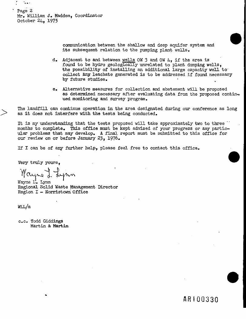
Page 2Mr. William J. Madden, CoordinatorOctober 24, 1975
communication between the shallow and deep aquifer system andits subsequent relation to the pumping plant wells.
d. Adjacent to and between wells OW 3 and OW 4T if the area isfound to be hydro geologically unrelated to plant dumping wells,the possibility of installing an additional large capacity well to'collect any leachate generated is to be addressed if found necessaryby future studies.
e. Alternative measures for collection and abatement will be proposedas determined necessary after evaluating data from the proposed contin-ued monitoring and survey program.
The landfill can continue operation in the area designated during our conference as longas it does not interfere with the tests being conducted.
It is my understanding that the tests proposed will take approximately two to threemonths to complete. This office must be kept advised of your progress or any partic-ular problems that may develop. A final report must be submitted to this office forour review on or before January 23, 19?6.
If I can be of any further help, please feel free to contact this office.
Very truly yours,
If CUy a J. l jAvWayne L. LynnRegional Solid Waste Management DirectorRegion I - Norristowri Office
WLL/m
c.c. Todd GiddingsMartin & Martin
ARIOQ330

DEPARTMENT OF ENVIRONMENTAL RESOURCES1875 New Hope Street
Norristown, Pennsylvania 19401 //£>*215 631-2413 J'
*
23. 1976 .Mr. William J. Madden, CoordinatorSpecial ProjectsFirestone Plastics CompanyChemical DivisionP.O. Box 699Pottstown, PA 19464 • Re: Expansion of Existing Firestone Landfill
ID #300001Dear Mr. Madden:
The following comments and recommendations were developed during our June 29, 1976meeting held in this office.
1. On-going hydrogeologic investigations have revealed two groundwater flowsystems, one flowing in the accumulated alluvium atop bedrock and a deepaquifer restricted to the underlying bedrock. The most recent datacollected indicates no to little hydraulic communication between the shallowand deep ground water flow systems. ____ _____________This finding indicates that any leachate emanating from the landfill orP.V.C. waste lagoons does not, as previously thought, become drawn intothe plant process wells composite cone of depression. ________
As a result of these and other findings, Firestone wishes to propose theunlined expansion of the existing fill in the area between the existingfill and unlined waste lagoons with the potential for the installationand utilization of a leachate collection system if and when it becomesnecessary as dictated by water quality analysis on newly installed, carefullyconstructed peripheral monitoring wells. The current contention andjustification for such a system is one of containment based on the •hydrogeologic findings that:
a) The existing landfill is not at field capacity and is in essencedry.
b) There is little hydraulic gradient in the shallow flow system.
c) The alluvial sediments have a slow lateral permeability.
d) Chemical data recently obtained from the new monitoring wellstend to indicate that contamination has not yet reached thosepoints.

EPA REGION IIISUPERFUND DOCUMENT MANAGEMENT SYSTEM
DOC IDPAGE n A& 1 00 32 2^
IMAGERY COVER SHEETUNSCANNABLE ITEM
SITE NAME Cospcrci'h°
OPERABLE UNIT
ADMINISTRATIVE RECORDS- SECTION VOLUME
REPORT OR DOCUMENT TITLE !>/«
•far ficMtll^l^Lg Oket c Cbsp /
DATE OF DOCUMENT
DESCR1PTON OF IMAGERY /vy - / a eX. z>eab/He+vftufre n
NUMBER AND TYPE OF IMAGERY ITEM(S) /
EPA REGION IIISUPERFUND DOCUMENT MANAGEMENT SYSTEM
DOC IDPAGE # -fl~ Io0'b'23'2>
IMAGERY COVER SHEETUNSCANNABLE ITEM
SITE NAME @£ c* d-t f* ** O if?-* ?*? £-<**-£ C sp .
OPERABLE UNIT
ADMINISTRATIVE RECORDS- SECTION_^T_VOLUME A
REPORT OR DOCUMENT TITLE £&*<£. OCo rf, PJ t• "£TPS~
O - M C c»rf. -PW H -Kvis:.*.
DATE OF DOCUMENT
DESCRIPTON OF IMAGERY fnQsrt, 5 *T° peqraf/ • / i
^ p/^•A/I *r
NUMBER AND TYPE OF IMAGERY ITEM(S) __ /_ o \/t <i t*t Mag -

EPA REGION IIISUPERFUND DOCUMENT MANAGEMENT SYSTEM
DOC IDPAGE #
IMAGERY COVER SHEETUNSCANNABLE ITEM
SITE NAME
OPERABLE UNIT
ADMINISTRATIVE RECORDS- SECTION / VOLUME
REPORT OR DOCUMENT TITLE P /a
DATE OF DOCUMENT
DESCRIPTON OF IMAGERY
NUMBER AND TYPE OF IMAGERY ITEM(S).