Purification and separation of carbon nanocapsules as a magnetic carrier for drug delivery systems
7
Purification and separation of carbon nanocapsules as a magnetic carrier for drug delivery systems Sunghoon Kim * , Etsuro Shibata, Ruslan Sergiienko, Takashi Nakamura Institute of Multidisciplinary Research for Advanced Materials, Tohoku University, 1,1 Katahira, 2-Chome, Aobaku, Sendai 980-8577, Japan ARTICLE INFO Article history: Received 11 March 2008 Accepted 1 May 2008 Available online 28 June 2008 ABSTRACT Nanoparticles of iron carbides wrapped in multilayered graphitic sheets (carbon nanocap- sules) were synthesized by electric plasma discharge in an ultrasonic cavitation field in liquid ethanol. The as-prepared material contained carbon nanocapsules but also included impurities such as amorphous carbon, graphite balls and flakes. These impurities must be removed to allow the development of applications for the carbon nanocapsules and, it is necessary to develop a suitable purification method to obtain samples of monodispersed carbon nanocapsules. Two purification methods were used. The first used a hydrogen per- oxide solution and acid etching to remove the amorphous carbon and iron particles. These impurities were easily oxidized and dissolved in the solution and the graphite layers of the carbon nanocapsules were not damaged. The second used magnetic separation using per- manent magnets to remove the graphite balls and flakes. Here, centrifugation was applied to separate the purified carbon nanocapsules around 100–200 nm in size. Ó 2008 Elsevier Ltd. All rights reserved. 1. Introduction Magnetic nanoparticles of pure metals such as Fe, Co and Ni are used as materials in various fields of magnetism. The main difficulty using pure metals arises from their instability towards oxidation in air, which become easier as the metal size becomes smaller. One approach to chemical stabilization is the formation of protective shells around the nanoparticle surface, which thus prevent the reaction of oxygen with the surface atoms [1,2]. Indeed, magnetic nanoparticles coated with protective shells are widely used in technological applications such as in the transport of anticancer drugs [3], and in magnetic recording materials [4] and have great potential in in vivo bio- medical applications such as in the contrast enhancement of magnetic resonance imaging (MRI) [5–9]. The carbon coating of metals presents an effective protection method against environmental degradation and has excellent adhesive bond- ing with the surface of the metal particles. Such carbon shells are airtight and protect the entrapped materials from oxida- tion, and they are generally known as ‘‘carbon nanocapsules’’. Such nanocapsules are proposed as a new approach of the magnetic carriers for the administration of drugs and vac- cines. One of the prospective medical applications of carbon nanocapsules can be the drug delivery to the specified targets which is controlled by a magnetic field [11–13]. The sizes of carbon nanocapsules are generally smaller than those of cells (10–100 lm), viruses (20–450 nm), proteins (5–50 nm) or genes (2 nm wide and 10–100 nm long) [10]. This means that these nanocapsules can ‘get close’ to a biological entity of interest. The targeted drug delivery using magnetic particles and an external magnetic field imposes several requirements on the adsorbent particles. The particles themselves must be biologically inert and biodegradable. Moreover, they must also have a high sorption capacity for the drug, and the rate of drug desorption in an organism needs to be slow so that the high concentration of the cytostatic drug can be maintained in the tumor area for a prolonged period of time. Since the 0008-6223/$ - see front matter Ó 2008 Elsevier Ltd. All rights reserved. doi:10.1016/j.carbon.2008.05.027 * Corresponding author: Fax: +81 22 217 5214. E-mail address: [email protected] (S. Kim). CARBON 46 (2008) 1523 – 1529 available at www.sciencedirect.com journal homepage: www.elsevier.com/locate/carbon
-
Upload
sunghoon-kim -
Category
Documents
-
view
215 -
download
3
Transcript of Purification and separation of carbon nanocapsules as a magnetic carrier for drug delivery systems
C A R B O N 4 6 ( 2 0 0 8 ) 1 5 2 3 – 1 5 2 9
. sc iencedi rec t . com
ava i lab le a t wwwjournal homepage: www.elsevier .com/ locate /carbon
Purification and separation of carbon nanocapsulesas a magnetic carrier for drug delivery systems
Sunghoon Kim*, Etsuro Shibata, Ruslan Sergiienko, Takashi Nakamura
Institute of Multidisciplinary Research for Advanced Materials, Tohoku University, 1,1 Katahira, 2-Chome, Aobaku, Sendai 980-8577, Japan
A R T I C L E I N F O
Article history:
Received 11 March 2008
Accepted 1 May 2008
Available online 28 June 2008
0008-6223/$ - see front matter � 2008 Elsevidoi:10.1016/j.carbon.2008.05.027
* Corresponding author: Fax: +81 22 217 5214E-mail address: [email protected]
A B S T R A C T
Nanoparticles of iron carbides wrapped in multilayered graphitic sheets (carbon nanocap-
sules) were synthesized by electric plasma discharge in an ultrasonic cavitation field in
liquid ethanol. The as-prepared material contained carbon nanocapsules but also included
impurities such as amorphous carbon, graphite balls and flakes. These impurities must be
removed to allow the development of applications for the carbon nanocapsules and, it is
necessary to develop a suitable purification method to obtain samples of monodispersed
carbon nanocapsules. Two purification methods were used. The first used a hydrogen per-
oxide solution and acid etching to remove the amorphous carbon and iron particles. These
impurities were easily oxidized and dissolved in the solution and the graphite layers of the
carbon nanocapsules were not damaged. The second used magnetic separation using per-
manent magnets to remove the graphite balls and flakes. Here, centrifugation was applied
to separate the purified carbon nanocapsules around 100–200 nm in size.
� 2008 Elsevier Ltd. All rights reserved.
1. Introduction
Magnetic nanoparticles of pure metals such as Fe, Co and Ni
are used as materials in various fields of magnetism. The
main difficulty using pure metals arises from their instability
towards oxidation in air, which become easier as the metal
size becomes smaller. One approach to chemical stabilization
is the formation of protective shells around the nanoparticle
surface, which thus prevent the reaction of oxygen with the
surface atoms [1,2].
Indeed, magnetic nanoparticles coated with protective
shells are widely used in technological applications such as
in the transport of anticancer drugs [3], and in magnetic
recording materials [4] and have great potential in in vivo bio-
medical applications such as in the contrast enhancement of
magnetic resonance imaging (MRI) [5–9]. The carbon coating
of metals presents an effective protection method against
environmental degradation and has excellent adhesive bond-
ing with the surface of the metal particles. Such carbon shells
er Ltd. All rights reserved
.u.ac.jp (S. Kim).
are airtight and protect the entrapped materials from oxida-
tion, and they are generally known as ‘‘carbon nanocapsules’’.
Such nanocapsules are proposed as a new approach of the
magnetic carriers for the administration of drugs and vac-
cines. One of the prospective medical applications of carbon
nanocapsules can be the drug delivery to the specified targets
which is controlled by a magnetic field [11–13]. The sizes of
carbon nanocapsules are generally smaller than those of cells
(10–100 lm), viruses (20–450 nm), proteins (5–50 nm) or genes
(2 nm wide and 10–100 nm long) [10]. This means that these
nanocapsules can ‘get close’ to a biological entity of interest.
The targeted drug delivery using magnetic particles and an
external magnetic field imposes several requirements on
the adsorbent particles. The particles themselves must be
biologically inert and biodegradable. Moreover, they must also
have a high sorption capacity for the drug, and the rate of
drug desorption in an organism needs to be slow so that the
high concentration of the cytostatic drug can be maintained
in the tumor area for a prolonged period of time. Since the
.
1524 C A R B O N 4 6 ( 2 0 0 8 ) 1 5 2 3 – 1 5 2 9
particles must be electively controlled by the applied mag-
netic field, both their magnetic properties and their dispersity
and agglomeration degree are important.
In this study, the carbon nanocapsules prepared by electric
plasma discharge in an ultrasonic cavitation field of liquid
ethanol, usually include impurities of the exposed metals
and other forms of carbon such as amorphous carbon, graph-
ite balls and flakes. Also, the electric plasma discharge meth-
od synthesizes particles with a wide size distribution. Thus,
the synthesized carbon nanocapsules are required to be puri-
fied to efficiently remove the impurities and control the size
distribution of the nanoparticles by a size-selection process
to be effective for further technological applications.
One of the conventional techniques for removing amor-
phous carbon involves the thermal or plasma cleaning with
Ox (x � 2) [13], while another technique concerns the treat-
ment with a toxic gas such as halogen [14]. However, these
techniques attack the graphite shell as well as amorphous
carbon, and may also require the disposal of hazardous sub-
stances. So, in this study, we have conducted a selective-oxi-
dation method using hydrogen peroxide, which is one of the
most safest and effective methods [15,16] for removing amor-
phous carbon, followed by acid treatment to remove the me-
tal impurities. Then, magnetic separation was conducted in
order to remove graphite balls and flakes, and centrifugation
was used to separate carbon nanocapsules around 100–
200 nm in size.
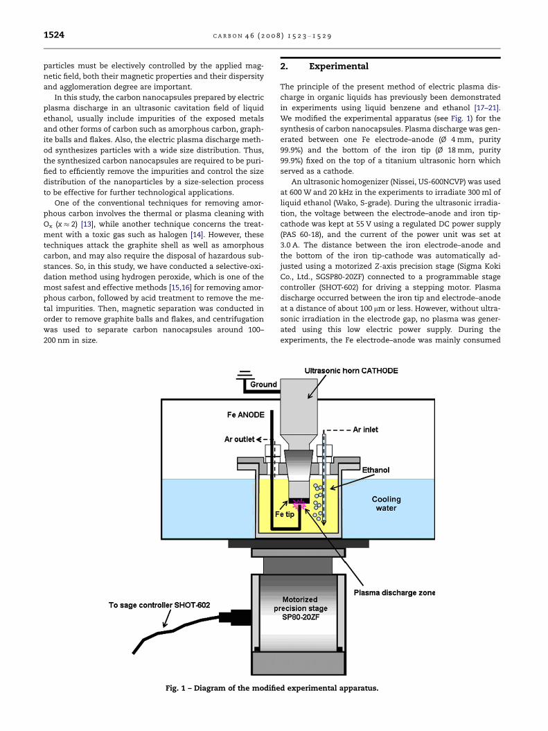
Fig. 1 – Diagram of the modifie
2. Experimental
The principle of the present method of electric plasma dis-
charge in organic liquids has previously been demonstrated
in experiments using liquid benzene and ethanol [17–21].
We modified the experimental apparatus (see Fig. 1) for the
synthesis of carbon nanocapsules. Plasma discharge was gen-
erated between one Fe electrode–anode (Ø 4 mm, purity
99.9%) and the bottom of the iron tip (Ø 18 mm, purity
99.9%) fixed on the top of a titanium ultrasonic horn which
served as a cathode.
An ultrasonic homogenizer (Nissei, US-600NCVP) was used
at 600 W and 20 kHz in the experiments to irradiate 300 ml of
liquid ethanol (Wako, S-grade). During the ultrasonic irradia-
tion, the voltage between the electrode–anode and iron tip-
cathode was kept at 55 V using a regulated DC power supply
(PAS 60-18), and the current of the power unit was set at
3.0 A. The distance between the iron electrode–anode and
the bottom of the iron tip-cathode was automatically ad-
justed using a motorized Z-axis precision stage (Sigma Koki
Co., Ltd., SGSP80-20ZF) connected to a programmable stage
controller (SHOT-602) for driving a stepping motor. Plasma
discharge occurred between the iron tip and electrode–anode
at a distance of about 100 lm or less. However, without ultra-
sonic irradiation in the electrode gap, no plasma was gener-
ated using this low electric power supply. During the
experiments, the Fe electrode–anode was mainly consumed
d experimental apparatus.
C A R B O N 4 6 ( 2 0 0 8 ) 1 5 2 3 – 1 5 2 9 1525
by thermal evaporation. The glass vessel was cooled in a
water bath and an argon gas flow was directed into the vessel
to maintain an inert atmosphere.
After the experiment, the synthesized carbonaceous pow-
der was separated from the liquid ethanol by centrifugation
and vacuum evaporation. A 200 mg sample of the as-prepared
powder was treated in 200 ml of 25% hydrogen peroxide
(Wako) solution refluxed at 90 �C for 40 h. After the hydrogen
peroxide treatment, the purified powder was separated by
centrifugation from the remaining hydrogen peroxide and
etched in 15% HCl solution for 4 h at room temperature to re-
move iron oxide particles. Finally, the purified carbon nano-
capsules were washed with distilled water five times, and
dried at 40 �C for 24 h in a vacuum oven.
The purified sample was dispersed in 50 ml of ethanol
solution by ultrasonic homogenization for 10 min. The graph-
ite balls and flakes were easily removed by magnetic separa-
tion [22,23]. The magnetic separator design includes the
application and travel of a permanent magnet near the wall
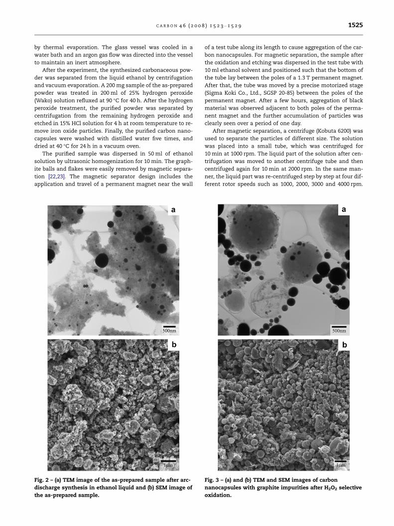
Fig. 2 – (a) TEM image of the as-prepared sample after arc-
discharge synthesis in ethanol liquid and (b) SEM image of
the as-prepared sample.
of a test tube along its length to cause aggregation of the car-
bon nanocapsules. For magnetic separation, the sample after
the oxidation and etching was dispersed in the test tube with
10 ml ethanol solvent and positioned such that the bottom of
the tube lay between the poles of a 1.3 T permanent magnet.
After that, the tube was moved by a precise motorized stage
(Sigma Koki Co., Ltd., SGSP 20-85) between the poles of the
permanent magnet. After a few hours, aggregation of black
material was observed adjacent to both poles of the perma-
nent magnet and the further accumulation of particles was
clearly seen over a period of one day.
After magnetic separation, a centrifuge (Kobuta 6200) was
used to separate the particles of different size. The solution
was placed into a small tube, which was centrifuged for
10 min at 1000 rpm. The liquid part of the solution after cen-
trifugation was moved to another centrifuge tube and then
centrifuged again for 10 min at 2000 rpm. In the same man-
ner, the liquid part was re-centrifuged step by step at four dif-
ferent rotor speeds such as 1000, 2000, 3000 and 4000 rpm.
Fig. 3 – (a) and (b) TEM and SEM images of carbon
nanocapsules with graphite impurities after H2O2 selective
oxidation.
1526 C A R B O N 4 6 ( 2 0 0 8 ) 1 5 2 3 – 1 5 2 9
After centrifugation, each sample was put into a vacuum oven
at 40 �C for 4 h.
The structure, morphology and size distribution of the
purified and separated carbon nanocapsules were evaluated
by 300 kV transmission electron microscopy (TEM) (JEOL,
JEM-3010) and field emission scanning electron microscopy
(FE-SEM) (JEOL, JSM-7000 F). The TEM and FE-SEM observa-
tions allowed us to determine the structure of the carbon
nanocapsules and the overall morphology of the samples.
Some of the observed nanocapsules were examined by means
of selected area electron diffraction (SAED) patterns and an
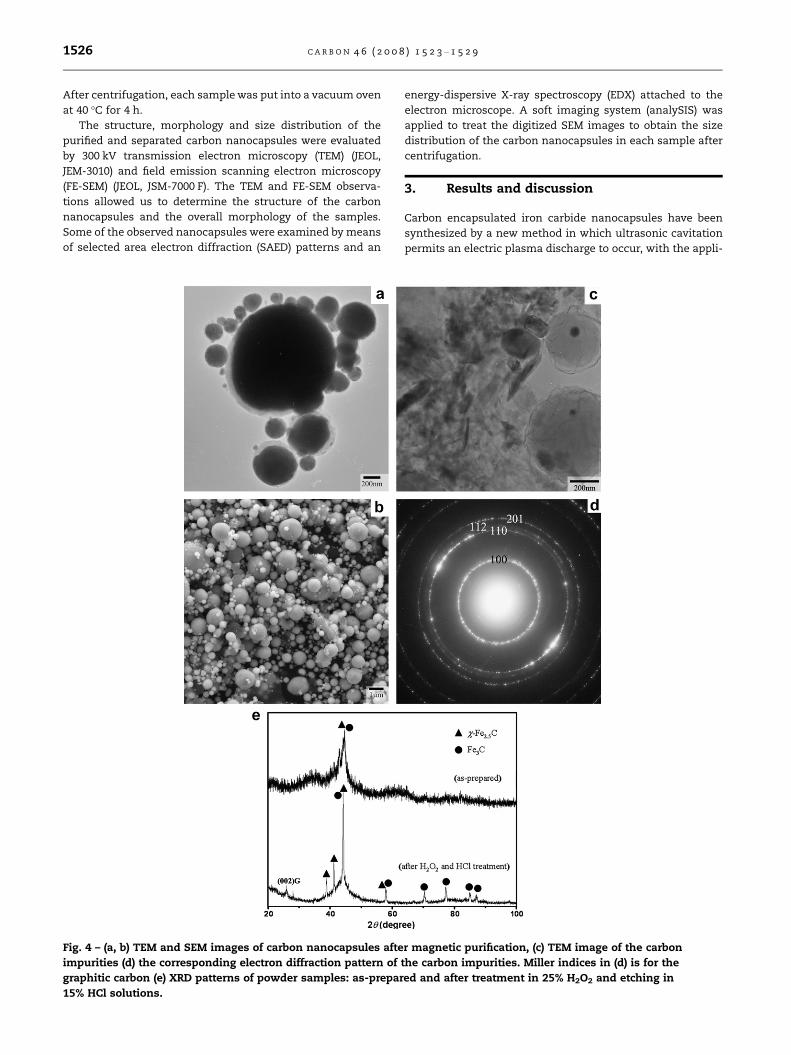
Fig. 4 – (a, b) TEM and SEM images of carbon nanocapsules afte
impurities (d) the corresponding electron diffraction pattern of
graphitic carbon (e) XRD patterns of powder samples: as-prepar
15% HCl solutions.
energy-dispersive X-ray spectroscopy (EDX) attached to the
electron microscope. A soft imaging system (analySIS) was
applied to treat the digitized SEM images to obtain the size
distribution of the carbon nanocapsules in each sample after
centrifugation.
3. Results and discussion
Carbon encapsulated iron carbide nanocapsules have been
synthesized by a new method in which ultrasonic cavitation
permits an electric plasma discharge to occur, with the appli-
r magnetic purification, (c) TEM image of the carbon
the carbon impurities. Miller indices in (d) is for the
ed and after treatment in 25% H2O2 and etching in
C A R B O N 4 6 ( 2 0 0 8 ) 1 5 2 3 – 1 5 2 9 1527
cation of a relatively low level of electric power even in insu-
lating ethanol [19,20]. TEM and SEM images revealed interest-
ing structural characteristics of the synthesized carbon
nanocapsules. Fig. 2a indicates that the spherical carbon
nanocapsules of the as-prepared sample ranged from as
small as 5 nm to as large as 1000 nm in diameter as already
shown in previous works [19,20]. A raw material, as shown
in Fig. 2a, was surrounded by amorphous carbon as impuri-
ties, graphite balls and also smaller carbon nanocapsules.
These amorphous carbon and graphite impurities came from
the thermal decomposition of ethanol by arc discharging. Fig.
2b shows a typical SEM image of raw material shown in Fig.
2a. Most of the carbon nanocapsules were covered by amor-
phous carbon impurities.
The morphological changes induced by the hydrogen per-
oxide and acid etching treatment are evident in the TEM and
SEM images, as shown in Fig. 3a and b. A comparison between
Figs. 2 and 3 show that the amorphous carbon and exposed
iron particles were mostly removed after the first purification
treatment with the hydrogen peroxide and acid solution. This
purification technique using hydrogen peroxide may have the
advantages of limited damage to the graphite shell and softer
reactions when compared with the previous acid purification
methods [23]. The TEM and SEM images in Fig. 3a and b re-
vealed other impurities such as large graphite balls and
graphite flakes, because this reaction did not remove graphite
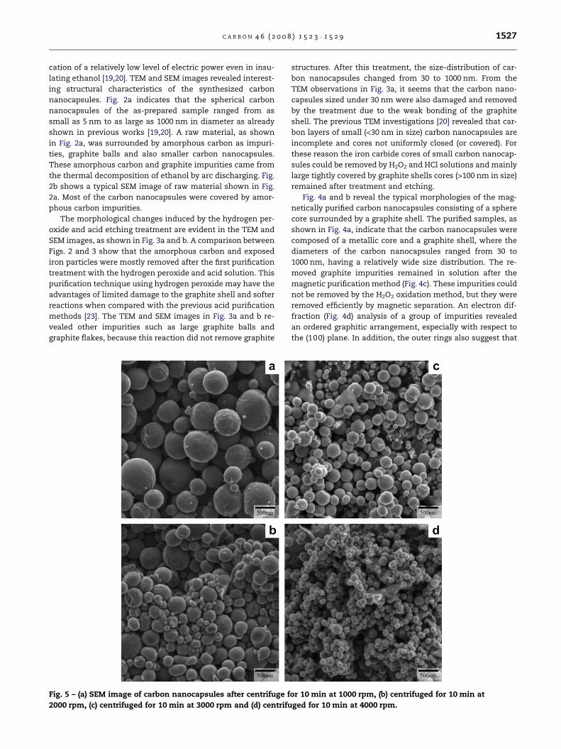
Fig. 5 – (a) SEM image of carbon nanocapsules after centrifuge f
2000 rpm, (c) centrifuged for 10 min at 3000 rpm and (d) centrifu
structures. After this treatment, the size-distribution of car-
bon nanocapsules changed from 30 to 1000 nm. From the
TEM observations in Fig. 3a, it seems that the carbon nano-
capsules sized under 30 nm were also damaged and removed
by the treatment due to the weak bonding of the graphite
shell. The previous TEM investigations [20] revealed that car-
bon layers of small (<30 nm in size) carbon nanocapsules are
incomplete and cores not uniformly closed (or covered). For
these reason the iron carbide cores of small carbon nanocap-
sules could be removed by H2O2 and HCl solutions and mainly
large tightly covered by graphite shells cores (>100 nm in size)
remained after treatment and etching.
Fig. 4a and b reveal the typical morphologies of the mag-
netically purified carbon nanocapsules consisting of a sphere
core surrounded by a graphite shell. The purified samples, as
shown in Fig. 4a, indicate that the carbon nanocapsules were
composed of a metallic core and a graphite shell, where the
diameters of the carbon nanocapsules ranged from 30 to
1000 nm, having a relatively wide size distribution. The re-
moved graphite impurities remained in solution after the
magnetic purification method (Fig. 4c). These impurities could
not be removed by the H2O2 oxidation method, but they were
removed efficiently by magnetic separation. An electron dif-
fraction (Fig. 4d) analysis of a group of impurities revealed
an ordered graphitic arrangement, especially with respect to
the (100) plane. In addition, the outer rings also suggest that
or 10 min at 1000 rpm, (b) centrifuged for 10 min at
ged for 10 min at 4000 rpm.
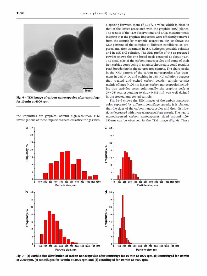
Fig. 6 – TEM image of carbon nanocapsules after centrifuge
for 10 min at 4000 rpm.
1528 C A R B O N 4 6 ( 2 0 0 8 ) 1 5 2 3 – 1 5 2 9
the impurities are graphite. Careful high-resolution TEM
investigations of these impurities revealed lattice fringes with
Fig. 7 – (a) Particle size distribution of carbon nanocapsules after
at 2000 rpm, (c) centrifuged for 10 min at 3000 rpm and (d) cent
a spacing between them of 3.38 A, a value which is close to
that of the lattice associated with the graphite (002) planes.
The results of the TEM observations and SAED measurements
indicate that the graphite impurities were efficiently removed
from the sample by magnetic separation. Fig. 4e shows the
XRD patterns of the samples at different conditions: as-pre-
pared and after treatment in 25% hydrogen peroxide solution
and in 15% HCl solution. The XRD profile of the as-prepared
powder shows the one broad peak centered at about 44.5�.The small size of the carbon nanocapsules and some of their
iron carbide cores being in an amorphous state could result in
peak broadening in the as-prepared sample. The sharp peaks
in the XRD pattern of the carbon nanocapsules after treat-
ment in 25% H2O2 and etching in 15% HCl solutions suggest
that, treated and etched carbon powder sample consist
mainly of large (>100 nm in size) carbon nanocapsules includ-
ing iron carbides cores. Additionally, the graphite peak at
2h = 26� (corresponding to d002 = 0.342 nm) was well defined
in the treated and etched sample.
Fig. 5a–d shows the SEM images of the carbon nanocap-
sules separated by different centrifuge speeds. It is obvious
that the sizes of the carbon nanocapsules and their distribu-
tions decreased with increasing centrifuge speeds. The nearly
monodispersed carbon nanocapsules sized around 100–
150 nm can be observed in the TEM image (Fig. 6). These
centrifuge for 10 min at 1000 rpm, (b) centrifuged for 10 min
rifuged for 10 min at 4000 rpm.
C A R B O N 4 6 ( 2 0 0 8 ) 1 5 2 3 – 1 5 2 9 1529
carbon nanocapsules are covered with a graphite shell around
5–8 nm in thickness and these purified nanocapsules are con-
sidered to be enough for use in further medical applications.
Fig. 7a–d shows the size distributions of the purified carbon
nanocapsules after each change in centrifuge speed. They
were measured and estimated from the SEM images as shown
in Fig. 5a–d. Centrifugation at 1000 rpm resulted in the widest
particle size distribution from 200 nm to 1200 nm. With
increasing centrifuge speed, the average size decreased and
the size distribution became narrower, as already confirmed
by the SEM images. After centrifuging for 10 min at
4000 rpm, the size of the carbon nanocapsules was around
100–200 nm, and the size distribution became sharper as
shown in Fig. 7d.
4. Conclusions
Carbon encapsulated iron carbide nanocapsules have been
synthesized by a new method in which ultrasonic cavitation
permits an electric plasma discharge to occur, with the appli-
cation of a relatively low level of electric power even in insu-
lating ethanol. The carbon encapsulated iron carbide
nanoparticles, ranging from 5 to 1000 nm in diameter, were
produced using an arc-discharge apparatus. Their crystalline
cores are spherical in shape, and surrounded by tightly
wrapped graphitic layers. Amorphous carbon impurities were
removed by H2O2 treatment, while the exposed iron particle
impurities were eliminated by 15% HCl solution. The graphite
impurities were easily removed by magnetic separation. After
magnetic separation, a centrifuge was used to obtain nearly
monodispersed particles around 100–200 nm in size after cen-
trifuging for 10 min at 4000 rpm. Finally, this study presents
for the first time a novel results to purify and separate carbon
nanocapsules of around 100–200 nm in size.
R E F E R E N C E S
[1] Dong XL, Zhang ZD, Jin SR, Sun WM, Zhao XG, Li ZJ, et al.Characterization of Fe–Ni(C) nanocapsules synthesized by arcdischarge in methane. J Mater Res 1999;14(5):1782.
[2] Wu W, Zhu Z, Liu Z, Xie Y, Zhang J, Hu T. Preparation ofcarbon-encapsulated iron carbide nanoparticles by anexplosion method. Carbon 2003;41(2):317.
[3] Kuznetsov AA, Filippov VI, Kuznetsov OA, Gerlivanov VG,Dobrinsky EK, Malashin SI. New ferro-carbon adsorbents formagnetically guided transport of anti-cancer drugs. J MagnMagn Mater 1999;194(1–3):22.
[4] Hanayama M, Ideno T. Magnetic recording medium. Jpn.Patent JP 06-152793.
[5] Carpenter EE. Iron nanoparticles as potential magneticcarriers. J Magn Magn Mater 2001;225(1–2):17.
[6] Umagai M, Imai Y, Nakamura T, Yamasaki Y, Sekino M, UenoS, et al. Iron hydroxide nanoparticles coated withpoly(ethylene glycol)-poly(aspartic acid) block copolymer as
novel magnetic resonance contrast agents for in vivo cancerimaging. Colloid Surf B: Biointerfaces 2007;56(1–2):174–81.
[7] Artemov D. Molecular magnetic resonance imaging withtargeted contrast agents. J Cell Biochem 2003;90(3):518–24.
[8] Schmitz SA. Iron-oxide-enhanced MR imaging ofinflammatory atherosclerotic lesions. Fortschr Rontgenstr2003;175:469–76.
[9] Kroft LJ, de Roos A. Blood pool contrast agents forcardiovascular MR imaging. J Magn Reson Imaging1999;10(3):395–403.
[10] Pankhurst QA, Connolly J, Jones SK, Dobson J. Applications ofmagnetic nanoparticles in biomedicine. J Phys D: Appl Phys2003;36:167–81.
[11] Tartaj P, Morales MD, Veintemillas-Verdaguer S, Gonzalez-Carreno T, Serna CJ. The preparation of magneticnanoparticles for applications in biomedicine. J Phys D: ApplPhys 2003;36:R182–97.
[12] Couvreur P, Gref R, Andrieux K, Malvy C. Microencapsulationpeptide and protein drugs delivery system. Colloid Surf B:Biointerfaces 2005;41(2):117–20.
[13] Park YS, Choi YC, Kim KS, Chung DC, Bae DJ, An KH, et al.High yield purification of multiwalled carbon nanotubes byselective oxidation during thermal annealing. Carbon2001;39(5):655–61.
[14] Hou PX, Bai S, Yang QH, Liu C, Cheng HM. Multi-steppurification of carbon nanotubes. Carbon 2002;40(1):81–5.
[15] Choi WK, Park SG, Takahashi H, Cho TH. Selective oxidationof single-walled carbon nanotubes using carbon dioxide.Carbon 2003;41(6):1221–30.
[16] Delzeit LD, Delzeit CJ. Carbon nanotube purification. USPatent 6972056 B1.
[17] Shibata E, Sergiienko R, Suwa H, Nakamura T. Synthesis ofamorphous carbon particles by an electric arc in theultrasonic cavitation field of liquid benzene. Carbon2004;42(4):885–901.
[18] Sergiienko R, Shibata E, Suwa H, Nakamura T, Akase Z,Shindo D. Synthesis of amorphous carbon nanoparticles andcarbon encapsulated metal nanoparticles in liquid benzeneby an electric plasma discharge in ultrasonic cavitation field.Ultrason Sonochem 2006;13(1):6–12.
[19] Sergiienko R, Shibata E, Akase Z, Suwa H, Nakamura T,Shindo D. Carbon encapsulated iron carbide nanoparticlessynthesized in ethanol by an electric plasma discharge in anultrasonic cavitation field. Mater Chem Phys 2006;98(1):34–8.
[20] Sergiienko R, Shibata E, Akase Z, Suwa H, Nakamura T,Shindo JD. Synthesis of Fe-filled carbon nanocapsules by anelectric plasma discharge in an ultrasonic cavitation field ofliquid ethanol. Mater Res 2006;21:2524–33.
[21] Sergiienko R, Shibata E, Akase Z, Shindo D, Nakamura T.Formation and characterization of graphite-encapsulatedcobalt nanoparticles synthesized by electric discharge in anultrasonic cavitation field of liquid ethanol. Acta Materialia2007;55(11):3671–80.
[22] Wiltshire JG, Li LJ, Khlobystov AN, Padbury CJ, Briggs GAD,Nicholas RJ. Magnetic separation of Fe catalyst from single-walled carbon nanotubes in an aqueous surfactant solution.Carbon 2005;43(6):1151–5.
[23] Thien-Nga L, Hernadi K, Ljubovic E, Garaj S, Forro L.Mechanical purification of single-walled carbon nanotubebundles from catalytic particles. Nano Lett2002;2(12):1349–52.