Published by Institution of Permanent Way Engineers · PDF filePublished by Institution of...
309
Transcript of Published by Institution of Permanent Way Engineers · PDF filePublished by Institution of...
Vinod
Placed Image

Published by Institution of Permanent Way Engineers (India)
Published Jan, 2005
Papers compiled by Technical Committee, IPWE(I), New Delhi, India
Designed & produced by Concept Graphic, Noida
Opinion expressed by Authors in the Technical Papers are not necessarily the opinion ofIPWE(India)
PREFACE
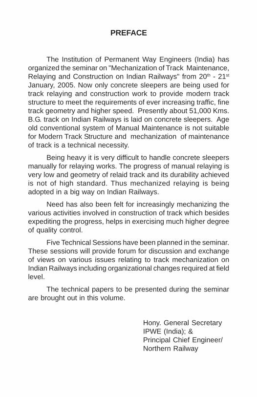
The Institution of Permanent Way Engineers (India) hasorganized the seminar on "Mechanization of Track Maintenance,Relaying and Construction on Indian Railways" from 20th - 21st
January, 2005. Now only concrete sleepers are being used fortrack relaying and construction work to provide modern trackstructure to meet the requirements of ever increasing traffic, finetrack geometry and higher speed. Presently about 51,000 Kms.B.G. track on Indian Railways is laid on concrete sleepers. Ageold conventional system of Manual Maintenance is not suitablefor Modern Track Structure and mechanization of maintenanceof track is a technical necessity.
Being heavy it is very difficult to handle concrete sleepersmanually for relaying works. The progress of manual relaying isvery low and geometry of relaid track and its durability achievedis not of high standard. Thus mechanized relaying is beingadopted in a big way on Indian Railways.
Need has also been felt for increasingly mechanizing thevarious activities involved in construction of track which besidesexpediting the progress, helps in exercising much higher degreeof quality control.
Five Technical Sessions have been planned in the seminar.These sessions will provide forum for discussion and exchangeof views on various issues relating to track mechanization onIndian Railways including organizational changes required at fieldlevel.
The technical papers to be presented during the seminarare brought out in this volume.
Hony. General SecretaryIPWE (India); &Principal Chief Engineer/Northern Railway
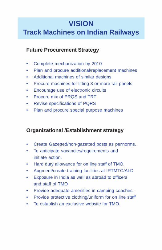
VISIONTrack Machines on Indian Railways
Future Procurement Strategy
• Complete mechanization by 2010• Plan and procure additional/replacement machines• Additional machines of similar designs• Procure machines for lifting 3 or more rail panels• Encourage use of electronic circuits• Procure mix of PRQS and TRT• Revise specifications of PQRS• Plan and procure special purpose machines
Organizational /Establishment strategy
• Create Gazetted/non-gazetted posts as pernorms.• To anticipate vacancies/requirements and
initiate action.• Hard duty allowance for on line staff of TMO.• Augment/create training facilities at IRTMTC/ALD.• Exposure in India as well as abroad to officers
and staff of TMO• Provide adequate amenities in camping coaches.• Provide protective clothing/uniform for on line staff• To establish an exclusive website for TMO.

Infrastructural Set up
• Create stabling sidings with working platform• Adequate communication facilities• Adequate number of camping coaches• Set up mobile repair vans
Working and Maintenance Strategy
• Set up divisional depot• Set up/upgrade zonal depot• Set up new POH workshop at SC• Need based maintenance policy for machines other
than tampers• Incorporate SOD below rail levels• Aim at excellent overhauling output• Switch over to unit exchange system
Spare parts management Strategy
• Develop drawing specifications andacceptance tests for procurement
• Exchange information on LPR quarterly• To have rate contracts with OEMs
THE INSTITUTION OF PERMANENT WAY ENGINEERS (INDIA)Governing Council
PresidentS.P. S. Jain,
Member Engineering, Railway BoardVice President
Budh Prakash,Addl. Member, Civil Engg., Railway Board
Hony. Genl. Secretary and Chairman Northern Railway CentreShri S. K. Vij,
Principal Chief Engineer, Northern RailwayHony. Treasurer
R K Gupta,Executive Director/Track (MC), Railway Board
Chairman of Zonal Centres1. C. K Narsimhan Principal Chief Engineer, Central Railway, Mumbai2. B. B. Saran Principal Chief Engineer, Eastern Railway. Kolkala3. A K Gupta Chief Engineer, East Central Railway, Hajipur4. S. K. Vij Principal Chief Engineer, Northern Railway, New Delhi5. Onkar Singh Chief Engineer, North Eastern Railway, Gorakhpur6. R. Ramanathan Chief Engineer, North East Frontier Railway, Guwahati7. K. K. Sharma Chief Engineer, North Western Railway, Jaipur8. D.C. Mitra Principal Chief Engineer, Southern Railway, Chennai9. R. K. Goyal Principal Chief Engineer, South Central Railway, Secunderabad10. Rajat Mitra Principal Chief Engineer, South Eastern Railway, Kolkata11. A. K. Goel Principal Chief Engineer, Western Railway, Mumbai12. K. Gangopadhyaya Chief Engineer, East Coast Railway, Bhubaneshwar13. R. N. Verma Principal Chief Engineer, North Central Railway, Allallabad14. P. Sriram Principal Chief Engineer, South Western Railway, Hubli15. Parth Sarathi Chief Engineer, West Central Railway, Jabalpur16. D.D. Devangan Chief Engineer, South East Central Railway, Bilaspur17. Anirudh Jain Executive Director(Track), RDSO, Lucknow18. Shiv Kumar Director, lRICEN, Pune
Executive Director, IPWEK. P .Singh
Executive Secretaries, IPWE1) H. L. Suthar 2) S.D. Sharma
CO-ORDINATION & VENUE SETUP COMMMITTEE
Convener Sh. Pankaj Jain,Chief Track EngineerNorthern Railway,Baroda House, New Delhi
Co-Convener Sh.T. Gupta,Chief Engineer/Const./CentralNorthern Railway,Kashmere Gate, Delhi
Member Secretary Sh.K.K.Miglani, Dy.CE/TONorthern Railway,Baroda House, New Delhi
Members Sh. V. K. Bali, Dy.CE/TMC/LineNorthern Railway,
Sh. D. P. Lal, Dy.CE/TPNorthern Railway,
Sh. R. B. Rai, Sr.DEN/Estate/DLINorthern Railway,
Sh. Rajbir Singh, DEN/E/DLINorthern Railway,
Sh. N. K. Kohli, XEN/TRNorthern Railway,
Sh. S. C. Gupta, AEN/DOT
Sh. O. P. Singh, AEN/Horticulture
Sh. S. P. Singh, SE/P.Way/Safety
Sh. V. K. Kataria, PWI/USFD/RF
Sh. Vipin Chhibbar, Suptd./DOT
NATIONAL TECHNIAL SEMINAR ON MECHANISATION
OF TRACK MAINTENCE, RELAYING & CONSTRUCTION
ON INDIAN RAILWAYS

TECHNICAL & SOUVENIR COMMITTEE
Convener Sh. Alok Ranjan,Chief Engineer/P&DNorthern Railway,Baroda House, New Delhi
Co-Convener Sh. S.N.Singh,Chief Engineer/TMCNorthern Railway,Baroda House, New Delhi
Sh. Anurag Sharma,Chief Engineer/C/NWNorthern Railway,Kashmere Gate, Delhi
Member Secretary Sh.Sunil Bhasker, Dy.CE/P&DNorthern Railway,Baroda House, New Delhi
Members Sh. R. C. Gupta, Dy.CE/TMMNorthern Railway,Baroda House, New Delhi
Sh. N. S. Negi, Dy.CE/MISNorthern Railway,Baroda House, New Delhi
Sh.Anjum Parvez,Dy.CE/C/TKJNorthern Railway
Sh. Mohd. Isha, XEN/P&DNorthern Railway
HOSPITALITY COMMITTEE
Convener Sh. Lalit Kapur,Chief Engineer/TSPNorthern Railway,Baroda House, New Delhi
Co-Convener Sh. A.K.Verma,Chief Engineer/C/NorthNorthern Railway,Kashmere Gate, Delhi
Member Secretary Sh.B.K..Gupta, Dy.CE/TS-IINorthern Railway,Baroda House, New Delhi
Members Sh. R. B. Rai, Sr.DEN/EstateNorthern Railway
Sh. S. S. Niyogi, TSO-INorthern Railway
Sh. B. K. Sharma, TSO/ IVNorthern Railway
Sh. Rajbir Singh, DEN/EstateNorthern Railway
Sh. O. P. Deshwal, AEN/Insp.
Sh. G. P. Sharma, PWI/TS

INVITATION COMMITTEE
Convener Sh. H.K.Jaggi,Chief Bridge Engineer
Northern Railway,Baroda House, New Delhi
Co-Convener Sh. Y.P. Singh,Chief Engineer/C/EastNorthern Railway,Kashmere Gate, Delhi
Member Secretary Sh. P.S..Gupta, Dy.CE/BDNorthern Railway,Baroda House, New Delhi
Members Sh. D. R. Dhingra, Dy.CE/Br.HQNorthern Railway
Sh. Ashok Kumar, Dy.CE/Const./PTNRNorthern Railway
Sh. Pankaj Gupta, XEN/Br. DesignNorthern Railway
Sh. D. K. Gulani, ABE/Design

ACCOMMODATION & TRANSPORT COMMITTEE
Convener Sh. Ashok Gupta,Chief Engineer/MRTSNorthern Railway,Baroda House, New Delhi
Co-Convener Sh. M.S.Rana,Chief Engineer/C/NENorthern Railway,Kashmere Gate, Delhi
Member Secretary Sh. S. P. Mahi,Sr.DEN/C/DLINorthern Railwayss
Members Sh. B. B. S. Tomar, Secy./Pr.CENorthern Railway
Sh. Jagtar Singh, Dy.CE/LandNorthern Railway
Sh. Anurag, Sr.DEN/I/DLINorthern Railway
Sh. Arun Shrivastava, Sr.DEN/V/DLINorthern Railway
Sh. R. B. Rai, Sr.DEN/Estate/DLINorthern Railway
Sh. R. N. Singh, Dy.CE/C/S.E.RoadNorthern Railway
Sh. S. P. Singh, XEN/LandNorthern Railway
Sh. Deep Sharma, AEN/NDLS
Sh. Ravneesh, AEN/Insp.
Sh. Suhel Ahmed, PWI/NDLS
Sh. Dinesh, IOW/MRTS
RECEPTION COMMITTEE
Convener Sh. Ved Pal, CE/GChief Engineer/GNorthern Railway,Baroda House, New Delhi
Co-Convener Sh. B.D.Garg,Chief Engineer/C/NorthNorthern Railway,Kashmere Gate, Delhi
Member Secretary Sh.Mudit Bhatnagar Sr.DEN/II/DLINorthern Railway, Delhi
Members Sh. A. K. Singh, Sr.DEN/III/DLINorthern Railway,
Sh. V. K. Gupta, DY.CE/WNorthern Railway,
Sh. Vinay Singh, Dy.CE/Const./Shivaji BridgeSh. Arjun Lal, XEN/G
Sh. D. N. Thakur, DEN/DEE
Sh. Bhagwan Malik, AEN/DLI
Sh. G. L. Meena, AEN/E/NDLS
Sh. Sanjay Puri, IOW/NDLS
Sh. Trehan, IOW/E/NZM
EXHIBITION & CULTURAL COMMITTEE
Convener Sh. S.N.Singh,Chief Engineer/TMCNorthern Railway,Baroda House, New Delhi
Co-Convener Sh. M.R.Choudhary,Chief Engineer/C/NCNorthern Railway,Kashmere Gate, Delhi
Member Secretary Sh. V. K.Bali, Dy.CE/TMC/LineNorthern Railway, Delhi
Members Sh. Arun Kr. Singh,Dy.CE/TMC/HQ, Northern RailwaySh. Rajendra Prasad, Dy.CE/TS-INorthern Railway
Sh. Y. K. Bhatnagar,Dy.CE/Br.Line/LPNRNorthern Railway
Sh. A. K. Nanda, Sr.DEN/IV/DLINorthern Railway
Sh. R. K. Sood, DEN/Track/DLINorthern Railway
Sh. Aamir Hamza, XEN/TMC/LineNorthern Railway
Sh. V. K. Singh, AENs/TMC
Sh. Mahender Kamra, AEN/Estate
Sh. Sunil Kumar, IOW/S.P. Road
SESSION – I
Theme: TRACK MAINTENANCE AND CONSTRUCTION:PLANNING AND UTILISATION OF MACHINES.
S.N. Title Authors
1. Safety in working of Rajat Mitra, Pr.CE/SER.Track machines – An overview. R. K. Srivastava, Dy.CE/TM/SER.
2. Role of Small Track Machines in Surendra Kumar, ED/TM/RDSO.Track Maintenance and Laying. A.K. Chakraborty, SE/TM/RDSO.
3. Planning and deployment of two T.V. Mahaganapathy,BCMs on same line and in single SSE/P.Way/Ambur./S.Rly.block section.
4. Planning and deployment of Rajesh Agarwal,Track Machines. Sr.DEN/HQ/Ratlam/WR
5. Role of small track machines in Narender Kumar, Dir/TM/RDSOconstruction of Track. B. P. Awasthi, Dir./TM/RDSO.
6. Planning, Utilisation and S. K. Singh, ARE/TM/RDSO,performance of on-track D.S. Prajapati, JE/Engg.-I/TM/RDSO.machines on Indian Railways.
National Technical Seminaron
Mecanisation of Track Maintenance,Relaying & Construction
on Indian Railways
Vinod
Placed Image
Vinod
Placed Image

SESSION – II
Theme: MECHANISATION OF TRACK MAINTENANCE ANDCONSTRUCTION : RECENT TRENDS ANDDEVELOPMENT.
S.N. Title Authors
1. Improving inherent Track R. K. Verma,Quality by Improved methods Sr. Prof./IRICEN/PAof Ballast compaction.
2. Complete Switch Maintenance. G. Robert Newman,Harsco Track Technologies,USA.
3. New Technologies to survey Ing. Rainer Wenty,and upgrade high capacity GM, Mktg & Tech saleslines. Plasser & Theurer, Austria.
4. Electronics Monitoring Alok Tiwari,System of Patrolling. Sr.DEN/Central/SBC/WC Rly
5. The role of rail grinding in Stuart L – Grassieimproving safety of the Consultant,Railway. Loram Maintenance of Way Inc
Vinod
Placed Image
Vinod
Placed Image
SESSION – III
Theme: MECHANISATION OF TRACK:INNOVATION AND CASE STUDIES.
S.N. Title Authors
1. 3X Tamper – B.Deva Singh,Modification on SCR. CTE/S.C. Rly.
2. Development of cost effective B.D. Sen, AEN/TMC/E.Rly.conveyor belt rivets and joining S. K. Sinha, SE/TMC/E.Rly.of open belts replacing endlessconveyors for FRM and BCM.
3. Precision Top table surfacing Mukesh Kumar,with track stabilization using Dy.C.E./Track Machinesthe Dynamic Track Stabilizer. E.C. Rly.
4. Mechanised Production & H.K. Jaggi, CBE/N. Rly.laying of Blanket Material S.K. Raina, ED/QA/RDSOin Railway embankment. P.K. Gupta, Dy.CE/Con./N.Rly.
5. Mechanised Track renewal Rajesh Prasad,by PQRS during night hours, Sr.DEN/C/SDAH/E.Rly.without power block and by A. K. Mishra,using contractor’s portal at AEN/Renaghat/E.Rly.base in Sealdah division.
6. Experience in use of Rail V.K. Bali,grinding machine on N. Railway. Dy.CE/TMC/Line/N. Rly.
7. Method to increase the Devinder Kumar,productivity of Ballast Sr.DEN(W)/CKP/S.E. Rly.cleaning machine.
Vinod
Placed Image
Vinod
Placed Image
SESSION – IV
Theme: MECHANISATION OF TRACK : CASE STUDIES.
S.N. Title Authors
1. Renewal of Diamond Crossing Sitesh Kumar Singh,layout by T-28 machine Sr.DEN/II/HWH/E.Rly.– A field experience.
2. Design Lining on busy routes. Ashish Agarwal, .ADEN/DRD/W.RRoopesh Gadekar,JE (P.way)/PLG/W.R.
3. T-28: Renewal of turnout, Sunil Gupta,rectification/ shifting of Sr.DEN(C),Ranchi/S.E.Rlycross overs (A case study)and suggestions.
4. Laying of diamond crossing Vivek Kumar Gupta,on PSC sleepers using Secretary to GM/C. Rly.T-28 machine on Indian Railways.
Vinod
Placed Image
Vinod
Placed Image

SESSION – V
Theme: MECHANISATION OF TRACK :ORGANISATIONAL ISSUES.
S.N. Title Authors
1. Future strategies for manpower J. C. Parihar, CTE/N.F. Rly.planning with adoption of Yogesh Wadhwa,mechanised maintenance Dy.CE/TD/NF Rlyof track. Baldev Singh,
DEN-I/Rangiya/N.F. Rly.
2. Three tier track maintenance G.C. Jain, Sr. DEN/HQ/BVP.system on Pipavav Railway V. K. MishraCorporation Ltd. SSE/P.Way/MMU/W.C. Rly.
3. Mechanised Maintenance of Amith Garg,track in Bangalore division Sr. D.E.N./Coord./Bangalore.– a unique concept.
4. Mechanisation of Track A. K. Chakraborty,Maintenance – Can it be S.E./TM/RDSO.optimised by mobilemechanised unit (MMU).
5. Track Maintenance on J. S. Mundrey,Indian Railways Formerly Advisor,– The missing Links. Civil Engg., Rly. Board.
Vinod
Placed Image
Vinod
Placed Image
1
SAFETY IN WORKING OFTRACK MACHINES- AN OVERVIEW
RAJAT MITRA*R.K.SRIVASTAVA**
SYNOPSIS
Mechanization of almost all activities related to laying,maintenance and renewal of track have come of age and we envisagecomplete mechanization of track maintenance in near future. Ourfocus have been mainly on improving utilization of track machinesand in this pursuit of improving utilization of track machines, safetyin working of track machine took a back seat. It is high time thatsafety in track machine working is given same importance as for it’sutilization so that system of working of track machines could be placedon sound footing. To identify the issues related to safety in trackmachines working, the author has gone in to the details of all thecases of accidents of track machines whether reported or not, whichhappened on S. E. railway during last ten years and areas which needsystem improvement to ensure safe working of track machines, havebeen discussed in this paper.
1.0 INTRODUCTION
Any working practice or activity related to working of trackmachines which has the potential of causing an accident within themeaning of accident defined in Accident manual is to be treated asunsafe working practice. Accident as defined in Accident manualnarrates that “Any occurrence which does or may affect the safety ofthe railway, its locomotion, rolling stock, permanent way, passengersor servants or which affects the safety of others or which does or maycause delays to trains or loss to the railway, is termed as an accident”.Keeping in view this definition of accident in mind, the author hasgone in to details of all the cases of accidents of track machines onS. E. Railway which have happened during the last 10 years andreasons of accident have been analyzed to identify unsafe workingpractices and suggestions have been made to eliminate these unsafeworking practices by improving the system of working of trackmachines.
* PCE/SER**Dy.CE/TM, SER

2
2.0 CASES OF ACCIDENT OF TRACK MACHINES OVERS. E. RAILWAY DURING THE PERIOD OF LAST 10 YEARS
All the cases of accident of track machines whether reported orunreported, have been taken in to consideration for the purpose ofsubject study. These cases of accidents have been listed below asper the classification of accident given in Accident Manual:
Sl. No. Accident Class ofAccident
I Collision of track machines with trackmachines/other vehicles A
II Averted Collision of track machines CIII Derailment of track machines BIV Accident caused by infringement
during working of track machines -V Failure of machines in block section
resulting in to disruption of traffic(for more than 4 hrs). H
VI Cases of run over of workmen atmachine site or knocked down by atrain at machine site. M
VII Cases of machine staff suffering injuryduring working & maintenance of trackmachines. P
Few specific cases under each type of accident of track machinesas classified above, have been described in the following paras:
2.1 Collision of Track Machines with Track Machines / otherVehicles
It is seen from the cases of collision of track machines that inall the cases of collision except one case, either BRM or DGS wasinvolved. Though all the cases of collision did not entail any majorinjury to staff or damage to machine but it is pertinent to deliberate oneach case of collision to understand the system failure behind it andthus, to prevent any disaster in future.
3
In one case, DGS machine while working between stationsGhunghuti – Badhwabara, Dn line of BSP division, collided with TowerWagon working in the same block section. Operator of this machineleft the machine unmanned without applying parking brake. There beingdown gradient, DGS rolled down and collided with Tower Wagon,causing injury to TW staff. It was found during enquiry that a mechanicof BCM was operating DGS for which he was not having the requisitecompetency certificate.
BRM machine while working between stations Talaburu –Kendposi, Dn line of CKP division, collided with Ballast cleaningmachine as operator of Ballast Regulating machine could not controlthe movement of machine. It was found during enquiry that a mechanicwas operating BRM machine for which he was not having the requisitecompetency certificate.
DGS while working between NMP – GKL of KGP division, collidedwith DUOMATIC machine because operator of DGS machine couldnot control the speed of machine well in time. It was found duringenquiry that operator was not having requisite knowledge andcompetency for operation of DGS.
CSM and DGS while working between Gangaghat – Gondiasection of NGP division, DGS collided with CSM because operator ofDGS could not control the machine well in time. It was found duringenquiry of this accident that a technician was operating DGS machine.
In all the above cases of collision, either DGS or BRM wasinvolved in the collision and reasons were same i.e non availability ofcompetent staff to operate these machines. It is a fact that machinelike BRM/DGS are generally operated by Technicians and other lowercategory staff due to shortage of manpower in track machineorganization. BRM and DGS not being a main machine in a group ofmachines working together, full complement of staff is not deputed onthese machines to save manpower. This thinking has proved counterproductive to safe working of machines. To avoid such accidents infuture, it is necessary that full complement of staff is posted not onlyin important machines but on all track machines.
In one case of collision, two CSMs were permitted to workbetween Contai Road and Bakhrabad stations of KGP division. Whilereturning to the base station after completion of work, one CSM hadto stop at home signal which was in ‘ON” position. Other CSM, which
4
was running behind, could not maintain the requisite distance due torestricted visibility and collided with CSM waiting at home signal. Thelesson learnt is that wherever machines are working in a group, realtime communication among machine operators must be available tosafeguard against such eventualities.
2.2 Cases of Averted Collision of Track Machines
There are few cases of averted collision but reasons behind thesecases of averted collision are quite revealing. Few specific cases ofaverted collision, have been described in following paras:
UNIMAT while working between Uluberia and Phuleswar stationsof KGP division, was to return back to Uluberia station after completionof block time. As the return movement of UNIMAT from site to Uluberiawas a Non-signal movement, machine was waiting at advance starterfor Pilot-In by station Staff. Cabin man waved signal to machine operatorallowing him to enter in to the station. At the same time, one passengertrain started from down loop towards advance starter of middle linecrossing through DN main line. On the face of approaching train,machine operator who had started moving towards DN M/L, stoppedjust start of passenger train. Driver of passenger train appliedemergency brake and collision was very narrowly averted. It was foundduring accident enquiry that starter signal to DN loop could be takenoff for the passenger train because the track machine was in non-track circuit portion between Advance starter and starter at that pointof time. The lesson learnt is that machine operator must insist forPilot In/Out memo whenever he has to make a non-signal movementor pass the signal at danger.
In one case of averted collision, traffic block was given betweenBagnan and Birshibpur station for working of 5 track machines. Thelast machine could not leave the station along with other four machinesbecause it developed some problem after crossing starter signal. After20 minutes, one passenger train was given starter signal for movementfrom DN Loop to middle line (It was a three line section i.e. UP, DN &Middle). By that time, the fifth machine which got stuck up betweenstarter and advance starter on DN main line, had also started movingtowards DN main. Collision of this machine with passenger train wasaverted by timely application of brake by operator of the machine aswell as by driver of the passenger train. Enquiry of this averted accidentrevealed that ASM on duty assumed that all the machines must have
5
entered in to block section of DN Main line but he did not verify thesame through porter. As the machine was stuck up between starterand advance starter in a non-track circuit portion, the ASM did notface any problem in taking off signal of DN loop starter. The lessonlearnt is that whenever machines are allowed to move in group from astation, ASM must ensure that all machines which are permitted formovement in a block section, have cleared the last stop signal. In theevent of any machine not being able to leave station immediately behindother machines which have already left, the paper block ticket of thatmachine should be taken back and machine should be brought backto a secure line from where it can leave only after getting fresh authorityfor movement from ASM of the station. Also, if operator of the machinefinds the he is not in a position to leave the station within reasonabletime, he should immediately advise the same to the station master.
One case of averted collision happened when CSM was returningto ADL station in right direction after working between SEL – ADL,DN/Line. Home signal was given for reception of a train on middle toDN M/Line but operator of the machine misunderstood the signal asthrough given for reception of machine on DN M/Line. However, collisionwas averted very narrowly by timely application of brake by operatorof the machine. The lesson learnt is that whenever a track machine isworking in a multiple line section, Road learning of the operator mustbe ensured.
In one case of averted collision, which happened on Garpos –Tangarmunda DN/Line of CKP division, CSM entered in this blocksection that was already occupied by a train. Section controller hadgiven order no. for imposition of traffic block after passage of this trainbut the machine was allowed to enter in to this section for workingassuming that by the time machine reaches the location of worksite,train will reach the station at other end. Incidentally, that train did notclear the section and a rear collision of machine with train was avertedby timely application of brake by operator of the machine. Accidentenquiry of this case revealed that ASM and PWI agreed to allow themachine in Block section to get more time for machine working. Thelesson learnt is that machine should be allowed to enter in the blocksection only after ensuring that last train has cleared the block sectionbefore imposition of block,
6
2.3 Derailment of Track Machines
In this part, few cases of derailment have been discussed whichhave taught lessons in improving the safety in working of trackmachines.
There are few cases of UNIMAT derailment on point becausepoint was not clamped after removing stretcher bar for machine packingsince points do open up during lifting & tamping operation. It has tobe made sure by machine operator and P. Way supervisor that pointis clamped before tamping.
There are cases of PQRS portal derailment due to poor conditionof AT at site. It is generally found that AT at site is not laid properlywhich not only affect the quality of renewed track but also causessuch derailment. Though, these derailments have not caused any injuryto staff or damage to machine, it resulted in to major bursting of block(i.e. line remain blocked for traffic for more than 4 hrs.)
There are few cases of derailment of gantry of TRT in which onecase of derailment of gantry, failure of bridge rail at location of invertedU joint caused the derailment and other case happened due to liftingof bridge rail at one end due to failure of locking pin. To prevent suchderailments, it has been made a part of daily maintenance of TRT toinspect the bridge rail at the location of U joint and locking pin for anycrack and wear.
During working of Ballast Regulating Machine, one joggledfishplate lying in the ballast came over railhead along with ballast andderailed the Ballast regulating machine. Therefore, it has to be madesure that no such obstructive materials exist in the ballast profilezone of track before working of track machines.
There are few cases of derailment of track machines duringshunting operation. All these cases of derailment of track machinesduring shunting operation happened because point was not clamped(Non interlocked points). No short cut should be permitted in shuntingoperation of track machines to prevent such derailment.
There is one case of machine derailment in which machinederailed because the operator did not remove skid before startingmovement of the machine.

7
2.4 Cases of accident caused by infringement during machineworking
There are few cases in which waste conveyor of BCM had hit theOHE mast and in all these cases, safety rod to protect the wasteconveyor from such structures like OHE mast/signal post by timelystopping the movement of machine, was not used. It has to be insistedthat machine staff use all safety devices to protect the machine fromsuch damage.
There is one case of such accident in which ballast guide plateof chain trough of SBCM, opened up during lifting of chain troughwhile closing the machine working. This opening of ballast guide platewas caused due to breakage of yoke connecting the actuator forcontrolling the movement of this plate. This ballast guide plate in raisedcondition caused infringement to moving dimension on adjacent line.It hit the leg of a person sitting on the footboard of an EMU train,which was passing on the adjacent track at the same time. The lessonlearnt from this accident, is that operator of machine should makesure that there is no train on adjacent line while operating any part ofthe machine which may cause infringement to adjacent lines.
2.5 Cases of breakdown of machines which resulted in tobursting of block for more than 4 hrs.
There are few cases of PQRS failure and T-28 failure, whichcaused major bursting of block. It revealed during enquiry thatemergency system of these machines were not in working order inone case of PQRS failure and T-28 failure. In other case of PQRS andT-28 failure, machine staff were not aware as how to use emergencysystem for winding up the machine to clear the section. The lessonlearnt from these accidents is that emergency system of all trackmachines, must remain functional and the same to be checked beforetaking any track machine for block working and machine In-charge toorganize a mock drill to train each and every staff of machine aboutthe use of emergency system.
2.6 Case of run over of workmen at machine site or knockeddown by a train causing serious injury
There is no case of run over but few cases of injury, whichhappened because machine staff could not hear the sound of the
8
train coming on adjacent line. The system of remote control hooterand actuation of hooter through Walkie-Talkie set will eliminate thistype of accident to a greater extent.
2.7 Cases of machine staff suffering injury during working /maintenance of track machines
There is good number of such cases in which staff sustainedinjury during operation/maintenance of machines. All these cases areattributable to lack of self-disciple and lack of use of safety devices/protective clothing while operating or maintaining the machine. Thoughmachine staffs have been provided with Helmet, Industrial grade Boot,dust protector and sound insulator, its usage by machine staff is notmuch. Most of the cases are of leg injury and in all these cases,machine staff was wearing “Chappal” which hardly protects the feetand prevent imbalance of body on slippery surface. The discipline onusage of these protective clothings and devices must be insisted uponmachine staff.
3.0 SUGGESTIONS
1) For movement and working of track machine at a station,which is not fully track circuited (Home to advance starteron double line/multiple line and advance starter at advancestarter in single line), occupation of track by machineshould be physically verified by station staff before allowingtrain movement.
2) Utilization and safety of machines like BRM and DGS mustnot be neglected over other important machines like BCM,CSM etc to ensure effective utilization and safe working ofthese important machines.
3) For Non-signal movement of machine, operator must seekPilot In/Out memo from the station. No such practice ofrelaying signal through body gesticulation should beaccepted as authority for movement of machine in to thestation.
4) Operator of machine must not move the machine over apoint and crossing when it has not been clamped if it is sorequired like for hand operated points. Also, operator of

9
UNIMAT should tamp Point & Crossing only after ensuringthat point has been clamped after removing the stretcherbars.
5) No track machine should be allowed in to a block section ifits’ emergency system is not in working order. Functioningof emergency system should be checked daily as a part ofdaily maintenance of machine.
6) Each machine site should be equipped with the hooterarrangement which can be operated remotely or throughWalkie-Talkie system, to relay audible warning well inadvance to all the staff working near machine, in case ofdouble and multiple line sections.
7) On a multiple line section or sections having special workingprinciple like twin single system, machine operator mustbe given road learning before allowing him to work in thatsection.
8) No machine staff should be allowed to perform duly withoutwearing Helmet and Shoes. Loss of manpower due to IODcases is a big financial loss to the system.
9) Devices in track machine to protect the machine fromdamage during its working, must remain functional and tobe used regularly which is generally bypassed by themachine operator.
10) Operator of track machine must ensure that necessarytrack protection on adjacent running line is availablewhenever such unit of the machine like wings of BRM, Chaintrough of BCM and FRM, are extended during working as itmay cause infringement to adjacent running lines,
Vinod
Placed Image
ROLE OF SMALL TRACK MACHINES IN TRACKMAINTENANCE AND LAYING
Surendra Kumar*,A.K.Chakraborty**
SYNOPSIS
Indian Railways is in transition stage regarding track maintenanceand laying practices. Demand for higher speed passenger traffic andheavy axle load compels to reduce track down time for maintenance.Presently the maintenance of track is done by manual as well asmechanized way. Due to changed socio-economic scenario, manualworks of maintenance and laying are no longer desirable and shouldbe replaced by mechanized methods. Use of more and moremachines, makes the maintenance and laying practice more efficientand quality oriented. This paper deals with deployment of small trackmachines, their functional aspects and latest innovations in this field.
1.0 INTRODUCTION
With upgraded track structure, track maintenance and layingpractices are becoming different as compared to that of earlier times.Concrete sleepers with elastic fastenings and higher rail section ofupgraded metallurgy need mechanised track maintenance and layingpractice. With this type of track structure, manual practice of work isbecoming almost impossible. Higher UTS rails and pre-stressed concretesleepers are prohibited from manual handling. Like wise packing ofconcrete sleeper track is to be done by mechanized way only. Althoughsmall track machines were developed more than a decade ago but non-acceptability of these machines hindered switching over to the mechanizedmaintenance practice. In this paper the design and functional aspects ofsome more commonly used small track machines alongwith few latestinnovations in this field has been covered in brief.
* Executive Director/TM, Track Machine and Monitoring Directorate, RDSO, Lucknow.** Section Engineer/Engg./TM, Track Machine and Monitoring Directorate, RDSO, Lucknow

2.0 DEPLOYMENT OF SMALL TRACK MACHINE IN TRACKMAINTENANCE ACTIVITIES
S.N. Type of work Activities invo- Type of STM that Remarkslving STM may be
deployed
1. Through i) Lifting, aligning & i) TRALIS / Mech or For aligningPacking correction of X- Hyd. Track jack. turn outs,(concrete level highersleeper track) ii) Renewal of ii) Heavy duty hydraulic capacity
damaged/ jammed extractor for TRALISfastenings jammed ERC. (as mentioned
iii) Spacing/ squaring iii) Hydraulic sleeper in para 6-b)of sleepers spacer.
iv) Packing of sleeper iv) Off-track tamperswith Hyd. Or Mech.Track Jack.
2. Repair to rail i) Rail cutting for i) a. Abrasive rail cutterfracture changing. b. Rail drilling machine(involving rail ii) Closure rail ii) Weld trimmerchanging) preparation iii) Rail profile weld grinder
iii) Welding of closurerai l .
iv) Finishing of weldedjoint.
3. Destressing of i) Cutting of closure i) Saw type rail cutterLWR /Abrasive rail cutter.
ii) Removal of fitting ii) Hyd. Extractor foriii) Rail tensioning jammed ERCs (if
(when destressing jammed ERCs exist).is done below td.) iii) Hydraulic Rail Tensor.
iv) Welding of closure. iv) Weld Trimmer.v ) Finishing of welded v ) Rail Profile
joint. Weld Grinder.
4. Adjustment of i) Pulling back of Hydraulic Rail Creepgap in SWR/ rails/ panels adjuster.Single rail fishplated track
5. Picking up i) Lifting of track i) Hyd ./ Mech. Trackslacks ii) Packing of sleepers lifting jack.
ii) Off-track tampers.
6. Correction of i) De-hogging of rail Hydraulic Rail jointhogged joints. ends. straightened.
7. Screening of i) Manual opening Semi-mechanisedshoulder ballast of ballast & ballast cleaner(during overhauling screening./remaining workof deep screeningleft over by BCM)

8. Re-alignment Slewing TRALIS For aligningof curve turn outs,
highercapacityTRALIS (asmentioned inpara 6-b)
9. Pulling back of Pulling back Hydraulic rail creeprails in fish adjuster.plated track
3.0 DEPLOYMENT OF SMALL TRACK MACHINES IN TRACK LAYING WORKS
S.N. Type of work Activities involving Type of STM that may RemarksSTM be deployed
1 . Laying of rail Pairing and butting Powered rail haulingon plain track on cess. s y s t e m
2 . Sleeper i) Unloading of sleeper i) jib crane attachable(concrete) ii) Carrying of concrete to BFR/BRHchanging on sleeper in case of ii) Attachment for railplain track. scattered renewal of dolly for transportation
sleeper in such of concrete sleeper.locations wheresleepers cannotbe unloaded.
3 . Welding of rails i) Making gap for i) Rail creep adjusterfor conversion welding. ii) Weld Trimmerof SWR/single ii) Weldingrails to LWR iii) Finishing of iii) Rail profile weldwelded joints grinder.
4 . Leading released Carrying released Rail Dollyrails rails/rail pieces for
rail changing site tonearest depot/stacking area.

4.0 SOME COMMONLY USED SMALL TRACK MACHINES
4.1 Hydraulic Rail Tensor
Main Features:
A hydraulically operated robust and rugged rail tensioningequipment
Pulling force – 70t, pushing force- 30t, hydraulic stroke – 300mm
Overall weight is 375 kg and maximum weight of heaviest partis 115 kg
Usefulness:
For Tensioning of rail during destressing of LWR when railtemperature is less than td.
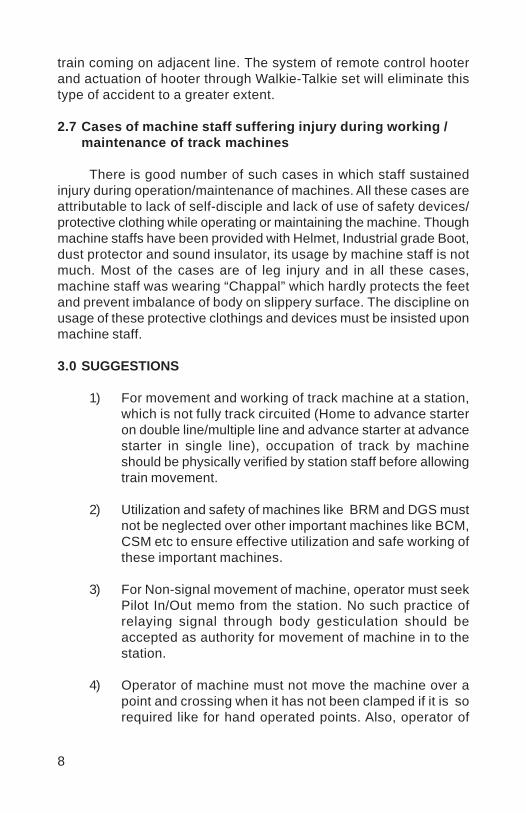
4.2 Weld Trimmer Power Pack version
Main Features:
A hydraulically operated trimming equipment powered byseparate power packShearing force upto 18 t is exerted on red hot weld.Trims the left over metal of the weld within the very short time of2 to 3 minutes
Usefulness:
Trimming of left over material of the weld during welding of rails.
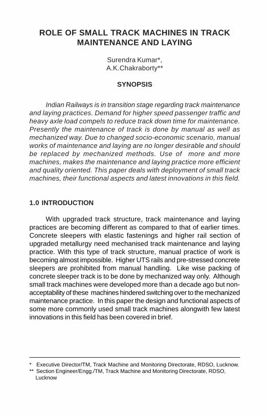
4.3 TRALIS (Track Lifting cum slewing device)
Main Features:
Hydraulically operated, state of art equipment for lifting andslewing of track simultaneously.Vertical Jack capacity – 10 t (15t for higher version), lateral jackcapacity – 5t (7.5 t for higher version)Vertical Jack lifting capacity- 80 mm (120mm for higher version),Slewing capacity – 50 mm on either side (150mm on eitherside for higher version)
Usefulness:
Correction of alignment of track/turnoutRe-alignment of curve
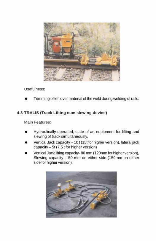
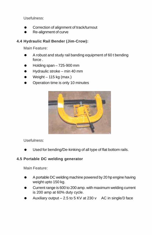
4.4 Hydraulic Rail Bender (Jim-Crow):
Main Feature:
A robust and study rail banding equipment of 60 t bendingforce .Holding span – 725-900 mmHydraulic stroke – min 40 mmWeight – 115 kg (max.)Operation time is only 10 minutes
Usefulness:
Used for bending/De-kinking of all type of flat bottom rails.
4.5 Portable DC welding generator
Main Feature:
A portable DC welding machine powered by 20 hp engine havingweight upto 150 kg.Current range is 600 to 200 amp. with maximum welding currentis 200 amp at 60% duty cycle.Auxiliary output – 2.5 to 5 KV at 230 v AC in single/3 face

Usefulness:
Very useful for reconditioning of worn out points andcrossings in situ.
4.6 Electronic Toe Load Measuring Device
Main Feature:
A handy device for measurement of toe load of ERC at site.Load cell capacity – 2000kg at – 50 C to +700C operatingtemperature.Display 8 or 16 character Alphanumeric.Weight – upto 10 kg
Usefulness:
Used to measure the toe load of elastic rail clips in service.
5.0 LESS POPULAR SMALL TRACK MACHINES WHICH AREEQUALLY USEFUL
5.1 Portable Shoulder Ballast Compactor :
Main Feature:
The compactor is powered by 3 to 3.5 hp engine (petrol/kerosene)Overall weight – 75 kgClimbing ability – Gradients and undulations up to 20%slope.
Usefulness:
Used for compaction of track ballast in crib and shoulder portionof Track.
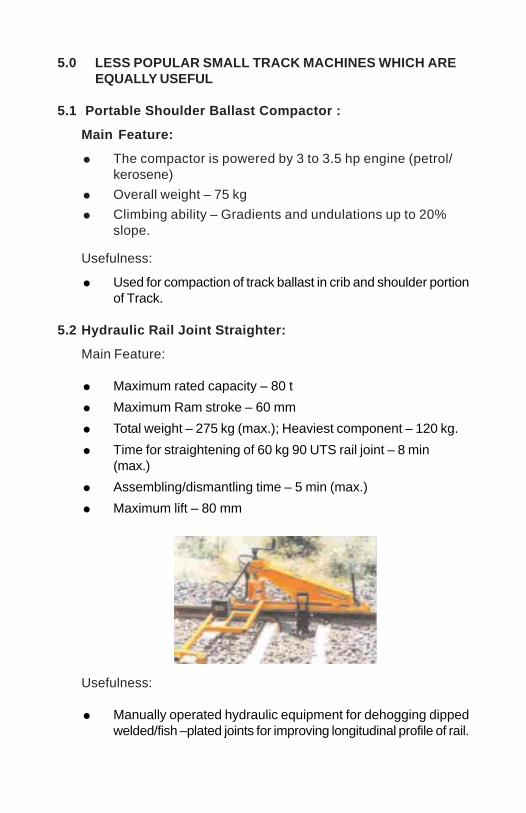
5.2 Hydraulic Rail Joint Straighter:
Main Feature:
Maximum rated capacity – 80 tMaximum Ram stroke – 60 mmTotal weight – 275 kg (max.); Heaviest component – 120 kg.Time for straightening of 60 kg 90 UTS rail joint – 8 min(max.)Assembling/dismantling time – 5 min (max.)Maximum lift – 80 mm
Usefulness:
Manually operated hydraulic equipment for dehogging dippedwelded/fish –plated joints for improving longitudinal profile of rail.

5.3 Powered Rail Hauling System:
Main Feature:
Weight of complete unit -190 kg
Engine capacity – 6 HP (Min.) at 1500 rpm
Fuel Tank capacity of engine – 4 lit. (min)
Mean rope hauling speed – 2-3 m/min.
Usefulness:
Pairing and butting edges of long welded rails (10/20 rail panels).
Hauling heavy material, structures, equipment duringconstruction, accidents, derailments etc.
5.4 Hydraulic Sleeper Spacer
Main Feature:
A light weight ( 14 kg) hydraulic equipment with rated capacityof 8 t.
Spacing capacity –125 mm + 75 mm (screw extension)
Operation time – 5 to 7 min.

Usefulness:
Used for re-spacing/ squaring of sleepers.
6.0 AVAILABILITY OF MANUFACTURERS AND SUPPLIERS:
For all the above mentioned machines, there are severalapproved vendors for each item cleared by Railway Board. Theapproved vendors are supplying the machines to zonal railways. Theapproved list of manufactures and suppliers of Small Track Machines&P-way measuring tools is issued time to time by Railway Board.
7.0 LATEST INNOVATIONS
7.1 Heavy duty hydraulic extractor for jammed ERC:
One model of 10 t capacityof the extractor was developedlong ago and is still available butnow a days, 10 t load isinsufficient and in the field it isobserved that average load of 12tto 17t is required to removemoderate to heavily jammedERCs. The weight of existingmodal is around 35 kg. In view

of this, higher capacity (30t) extractor has been successfully evolved.Technical features of the equipment are as follows:
(i) Maximum Pushing force : 25t to 30 t (pressure release valve tobe set to release between 29t and 30 t)
(ii) Hydraulic stroke (Max.) : 40 mm to 50 mm
(iii) Weight without oil & : 30 kg (Max.)J-hooks
(iv) Fixing/Removing time : 05 Minutes (Max.)
(v) Extraction time : Depends upon the extent of jammingand generally it is less than 7 min.
(vi) Pressure pin size : Taper (22 mm Ø x 19 mmØ), length95 mm, 100 mm and 105 mm.(Different lengths are required foroverdriven, correctly driven andunder driven ERCs.)
Prototypes of such high capacity extractor have been successfullytested in field for removing jammed ERCs. Some of the field trialobservations are given below:
Field trial details of hydraulic ERC extractor (higher capacity):
i) Location: Dn Main Line at KM 211/22-20 & 211/02-32 nearAsansol Station.
ii) Sample No. 01
Vinod
Placed Image
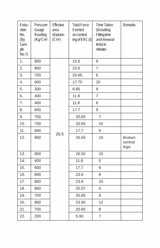
Extra- Pressure Effective Total Force Time Taken Remarksction Gauge area Exerted (IncludingNo. Reading of piston on central Fitting time(By (Kg/ Cm2 (Cm2) leg of ERC (t) and removalSam- time) inple minutesNo.1)1. 800 23.6 9
2. 800 23.6 7
3. 700 20.65 6
4. 600 17.70 10
5. 300 8.85 8
6. 400 11.8 7
7. 400 11.8 6
8. 600 17.7 9
9. 700 20.65 7
10. 700 20.65 10
11. 600 17.7 6
12. 900 29.5 26.55 10 Brokencentrallegs.
13. 900 26.55 10
14. 400 11.8 5
15. 600 17.7 6
16. 800 23.6 8
17. 800 23.6 10
18. 850 25.07 5
19. 700 20.65 8
20. 800 23.60 12
21. 700 20.65 8
22. 200 5.90 7
29.5

Extra- Pressure Effective Total Force Time Taken Remarksction Gauge area Exerted (IncludingNo.(By Reading of piston on central Fitting timeSam- (Kg/ Cm2 (Cm2) leg of ERC (t) and removalple time) inNo.1) minutes
1. 600 17.7 6
2. 300 8.85 6
3. 400 11.8 8
4. 400 11.8 7
5. 300 8.85 6
6. 800 23.6 10 Heavilyjammed
7. 900 26.55 7
8. 800 23.6 8
9. 850 25.07 8
10. 700 20.65 6
11 700 20.65 10
12. 600 17.7 6
13. 600 17.7 8
14. 800 23.6 10
15. 850 25.07 7
16. 600 17.7 10
17. 400 11.8 6
18. 800 23.6 7
19. 600 17.7 10
20. 400 11.80 12
21. 600 17.70 7
22. 600 17.70 7
23. 400 11.80 8
24. 400 11.80 6
25. 800 23.60 7
29.5
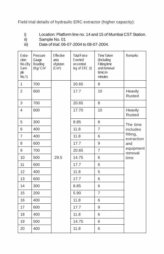
Field trial details of hydraulic ERC extractor (higher capacity):
i) Location: Platform line no. 14 and 15 of Mumbai CST Station.ii) Sample No. 01iii) Date of trial: 06-07-2004 to 08-07-2004.
Extra- Pressure Effective Total Force Time Taken Remarksction Gauge area Exerted (IncludingNo.(By Reading of piston on central Fitting timeSam- (Kg/ Cm2 (Cm2) leg of ERC (t) and removalple time) inNo.1) minutes
1 700 20.65 8
2 600 17.7 10 HeavilyRusted
3 700 20.65 8
4 600 17.70 10 HeavilyRusted
5 300 8.85 8 .
6 400 11.8 7
7 400 11.8 6
8 600 17.7 9
9 700 20.65 7
10 500 29.5 14.75 6
11 600 17.7 6
12 400 11.8 5
13 600 17.7 6
14 300 8.85 6
15 200 5.90 7
16 400 11.8 6
17 600 17.7 9
18 400 11.8 6
19 500 14.75 6
20 400 11.8 6
The timeincludesfitting,extractionandequipmentremovaltime
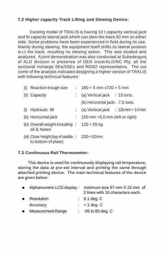
7.2 Higher capacity Track Lifting and Slewing Device:
Existing model of TRALIS is having 10 t capacity vertical jackand 5t capacity lateral jack which can slew the track 50 mm on eitherside. Some problems have been experienced in field during its use.Mainly during slewing, the equipment itself shifts its lateral positionw.r.t the track, resulting no slewing action. This was studied andanalyzed. A joint demonstration was also conducted at Subedergunjof ALD division in presence of DEN track/ALD/NC Rly, all thesectional incharge SEs/SSEs and RDSO representative. The outcome of the analysis indicated designing a higher version of TRALISwith following technical features:
(i) Reaction trough size : 180 + 5 mm x720 + 5 mm
(ii) Capacity : (a) Vertical jack : 15 tons.
(b) Horizontal jack : 7.5 tons.
(i) Hydraulic lift : (a) Vertical jack : 120 mm + 5.0 mm
(b) Horizontal jack : 150 mm +5.0 mm (left or right)
(iv) Overall weight including : 120 + 05 kgoil & hoses
(vi) Close Height (top of saddle : 230+ 02mmto bottom of plate)
7.3 Continuous Rail Thermometer:
This device is used for continuously displaying rail temperature,storing the data at pre-set interval and printing the same throughattached printing device. The main technical features of the deviceare given below:
Alphanumeric LCD display : minimum size 97 mm X 22 mm of2 lines with 16 characters each.
Resolution : 0.1 deg. CAccuracy : + 1 deg. CMeasurement Range : -05 to 85 deg. C
7.4 Train Speed Recorder
Train Speed Recorder is a device for measurement of speed ofthe passing train in both double and single line track. The instrumentcan be preset at any desired speed upto 200 kmph and the print outwill mark all speeds above the preset speed as ‘ excess speed’. Themain technical features of the recorder are given below:
i) Range of Speed : 01 to 200 kmphii) Traffic condition : Bi-directional on double lines.iii) Mode of speed : Repetitive speed measurement on
Measurement passage of atleast every fourthwheel set.
iv) Tolerance of speed : 01% for all speeds.measurement
v) Calendar and time : High stability crystal based realrecorder time clock to drive calendar & time
with an accuracy of 1 micro sec.vi) Weight of the instrument : Maximum 20 kg (Approx.)
including battery, cable etc.
8.0 CONCLUSION
Track maintenance and laying require right type of machine,trained manpower and acceptability of mechanised way of trackmaintenance and laying works. With modern track structure, there isno other option but to switch over to mechanised maintenance & layingpractices. Counseling/training of the users at the grass root level,solving the field problems, proper maintenance and repairinginfrastructure at divisional level are the key points to enhance theacceptability of mechanised system of maintenance and laying oftrack.
Vinod
Placed Image

1
PLANNING AND DEPLOYMENT OF TWO BCMsON SAME LINE AND IN SINGLE BLOCK SECTION
T.V. MAHAGANAPATHY *
SYNOPSIS
Deep screening is one of the regular track maintenanceactivities to be done once in 10 years. In PSC sleeper track it isessential to deploy BCM for deep screening work for ensuringquality and high progress. Even though the BCM gives moreprogress than the manual deep screening in normal conditions,the traffic density and availability of line blocks, compelled us tothink about deploying more than one track machine in a singleblock section. The deep screening work by BCM involves impositionof speed restrictions in addition to line block requirement. Tomaximize the utilization of speed restrictions and line blocks, twoBCMs were deployed for ballast cleaning work in the same blocksection in SSE/P.Way/Ambur section. The experience gained isbrought out in this technical paper.
* SSE/P.Way/Ambur
(A) PLANNING
1.0 ASSESSMENT OF BALLAST REQUIREMENT
1 m length of track was deep screened at every 1 km and quantityof ballast deficient was computed. The deficiency was 0.6 to 0.65cum per meter length of track.
2.0 PLANNING OF SIMULTANEOUS ACTIVITIES
Following activities were planned and executed simultaneously1. Isolation of LWR2. BCM working3. Destressing4 Replacement of broken sleepers.5. Recoupment of missing fastenings.6 Ensuring Zero missing fittings.
2
7. Painting of liner seat8. Shifting of liner seat.
3.0 PRELIMINARY WORKS FOR DEPLOYING LARGE SCALEON TRACK MACHINES
3.1 Foot by foot survey was conducted prior to deploying BCM.
3.2 Fixed structures likely to infringe cutter movement are notedand MCD for cutter chain diagram was prepared.
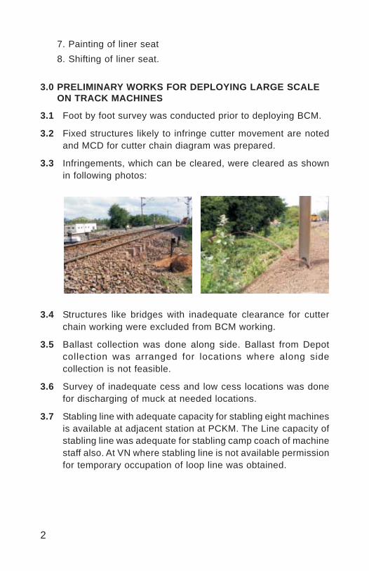
3.3 Infringements, which can be cleared, were cleared as shownin following photos:
3.4 Structures like bridges with inadequate clearance for cutterchain working were excluded from BCM working.
3.5 Ballast collection was done along side. Ballast from Depotcollection was arranged for locations where along sidecollection is not feasible.
3.6 Survey of inadequate cess and low cess locations was donefor discharging of muck at needed locations.
3.7 Stabling line with adequate capacity for stabling eight machinesis available at adjacent station at PCKM. The Line capacity ofstabling line was adequate for stabling camp coach of machinestaff also. At VN where stabling line is not available permissionfor temporary occupation of loop line was obtained.
3
3.8 There was difficulty in getting water, power supply, and toileteffluent disposal to camp coach. To overcome this problem
i) A temporary water tank was erected near stabling line.
ii) A vacant quarter was allotted as rest house formachine staff.
3.9 Diesel stockyard was created near stabling line.
3.10 Watch man was arranged at stabling site for round the clockguarding of machines and materials.
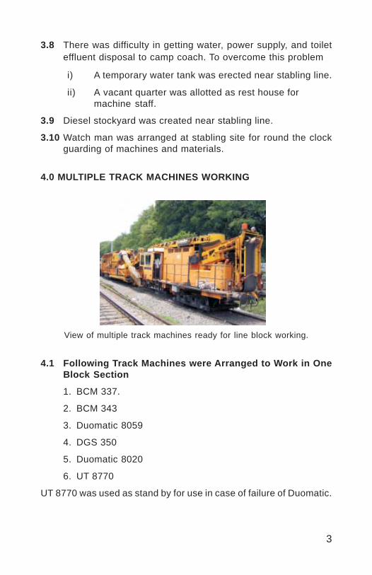
4.0 MULTIPLE TRACK MACHINES WORKING
4.1 Following Track Machines were Arranged to Work in OneBlock Section
1. BCM 337.
2. BCM 343
3. Duomatic 8059
4. DGS 350
5. Duomatic 8020
6. UT 8770
UT 8770 was used as stand by for use in case of failure of Duomatic.
View of multiple track machines ready for line block working.
4
S.No Activities Requirementof JE/SE
1 Tamper two machines 12 BCM two machines 23 Welding 14 De stressing 15 Casual renewal of sleepers 1
& Other activitiesTotal 6
5.0 REQUIREMENTS OF SUPERVISORS
The minimum requirement of JE/SE is difficult to provide.Presently work sites are managed with 50% of requirements. If fullrequirement of JE/SE are provided there is scope for furtherimproving quality.
6.0 OTHER ACTIVITIES
6.1 Removal of guard rails and check rails
6.2 Obstructions such as cables, joggled FP removal
6.3 Portable welding plant for reconditioning of Track Machine tools
6.4 Checking of parameters during tamping and BCM working
7.0.CONTRACT FOR BCM WORKING
Contract for BCM working was awarded with following provisions.
1. Screening of ballast left out by BCM at shoulder portions
2. De-stressing
3. Rail cutting
4. Hole drilling
5. BCM line block working
6. Welding
7. Post tamping work
5
(B) DEPLOYMENT OF BCMS
8.0 BCM WORKING – PRE REQUISITES.
Following were ensured for deployment of BCM1. Minimum ballast cushion 250 mm. This requirement was
already achieved during cushioning work. Hence no lifting oftrack was done.
2. Foot by foot survey to assess width of ballast, cess width, landavailability for waste disposal.
3. Survey and plotting of longitudinal profile and re alignment ofcurve
4. Gas cutting and welding plant for reconditioning tamping, BCMtools and cutting and removing obstructions.
5. Peg marking of final levels6. Signal rod, cables likely to infringe BCM cutters shifted
temporarily.7. Approaches to bridges that cannot be screened by the machine
screened manually.8. Opening of LC programmed.9. Sleeper’s fastenings intact.10. Special precautions for disposing soil while working in cutting
and station yards.11. A trench of 30 cm depth and one metre width should be made
for lowering cutter bars duly re-spacing of sleepers.
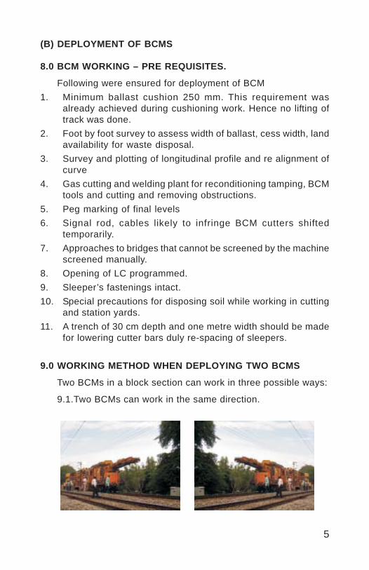
9.0 WORKING METHOD WHEN DEPLOYING TWO BCMS
Two BCMs in a block section can work in three possible ways:
9.1.Two BCMs can work in the same direction.
6
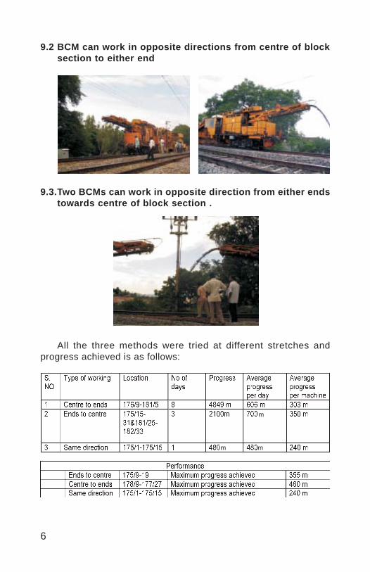
9.2 BCM can work in opposite directions from centre of blocksection to either end
9.3.Two BCMs can work in opposite direction from either endstowards centre of block section .
All the three methods were tried at different stretches andprogress achieved is as follows:
m
m m

7
10.0 ADVANTAGES AND DISADVANTAGES OF DIFFERENTMETHODS OF WORKING
10.1 Advantages of BCM working in Same Direction
a) Work was done with single work caution with overlapping speedrestrictions. Pre decided output was achieved.
b) Effective supervision and control was possible as all machinesare working in close proximity.
c) No confusion to drivers in observing speed restriction as itwas single overlapping speed restrictions in a block section.
d) Length of caution and engineering time loss were least
e) Work can be done with single tamping machine
10.2 Disadvantages of BCM working in Same Direction
a) During failure of BCM progress of two days works gettingaffected due to programmed progress could not be achievedon that date and BCM has to be deployed for screening previousday left out work
b) Shifting of cutter chain to be done daily.
c) Optimum utilization of rear BCM is not possible.
10.3 Disadvantages of BCM working in Opposite Direction:
a) Work was commenced with a single caution. As the workprogresses it becomes two work cautions with over lappingspeed restrictions.
b) On completion of each days work distance between BCMincreases requiring independent supervisors for each set ofmachines.
c) Length of caution increased.
d) Two work cautions in the same block section caused confusionto some goods train drivers while observing second cautiondue to over lapping of train formation in both the cautions.
10.4 Advantage of BCMs working in Opposite Direction:
Optimum utilization of both the BCMs is possible from the secondday onwards.

8
11.0 ACTIVITIES AND SPEED RESTRICTIONS
11.1 During the entire period of work railtemperature was recorded and it was460 to 480 and within temperature range oftd +100 C to td-200C (td=460; range oftemperature 260 to 560)
11.2. Operation During Traffic Block
a) Lowering of cutter bar

9
b) When the machine starts working one person should movewith the machine to watch for obstructions to cutter chain.
c) Immediate stopping of machine in case of obstruction to cutterchain for taking corrective actions.
d) Screening to be stopped 30 minutes before expiry of trafficblock to permit closing and clearing within the block time.
e) If the machine stopped moving during work closing of cleanballast out let to be ensured to avoid heaping up of screenedballast at one place.
f) Safety switches provided to sense the mast to be kept on toavoid waste disposing conveyer hitting against electrical mast.
g) Safety helmet and mask to be worn by all staff working withmachine.
h) While closing work 5 sleeper spaces are left without ballast, tobe filled with ballast manually.
i) Checking vertical and lateral clearances before clearing lineblock.
j) Posting of watchman at cutter bar location.
k) One round of tamping along with DTS after BCM speed can beraised to 30 kmph.
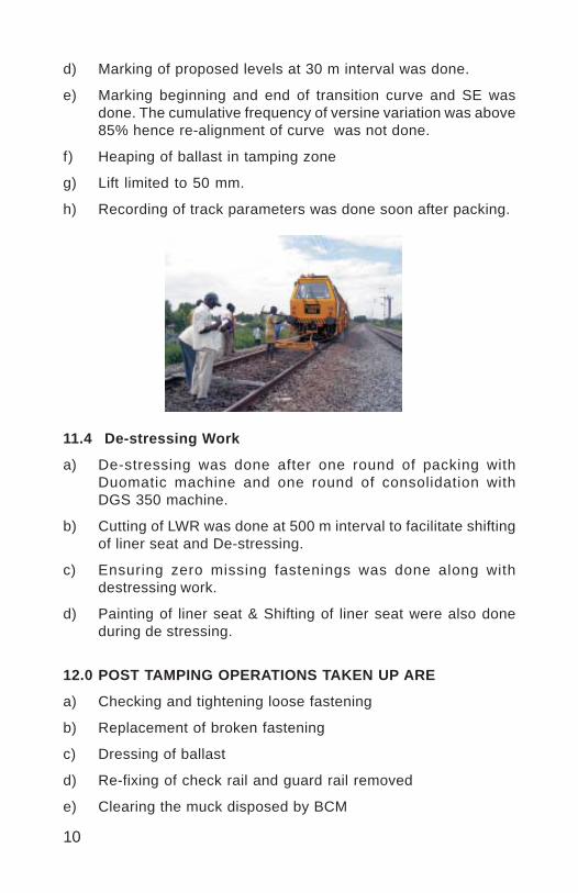
11.3 Rear Packing and DTS Working
a) Availability of adequate ballast at shoulder and crib for 20 mmlift was ensured.
b) Training out of ballast for locations where along side collectionwas not feasible was done.
c) Squaring of sleepers and spacing adjustments was done soonafter BCM working.
10
d) Marking of proposed levels at 30 m interval was done.
e) Marking beginning and end of transition curve and SE wasdone. The cumulative frequency of versine variation was above85% hence re-alignment of curve was not done.
f) Heaping of ballast in tamping zone
g) Lift limited to 50 mm.
h) Recording of track parameters was done soon after packing.
11.4 De-stressing Work
a) De-stressing was done after one round of packing withDuomatic machine and one round of consolidation withDGS 350 machine.
b) Cutting of LWR was done at 500 m interval to facilitate shiftingof liner seat and De-stressing.
c) Ensuring zero missing fastenings was done along withdestressing work.
d) Painting of liner seat & Shifting of liner seat were also doneduring de stressing.
12.0 POST TAMPING OPERATIONS TAKEN UP ARE
a) Checking and tightening loose fastening
b) Replacement of broken fastening
c) Dressing of ballast
d) Re-fixing of check rail and guard rail removed
e) Clearing the muck disposed by BCM
11
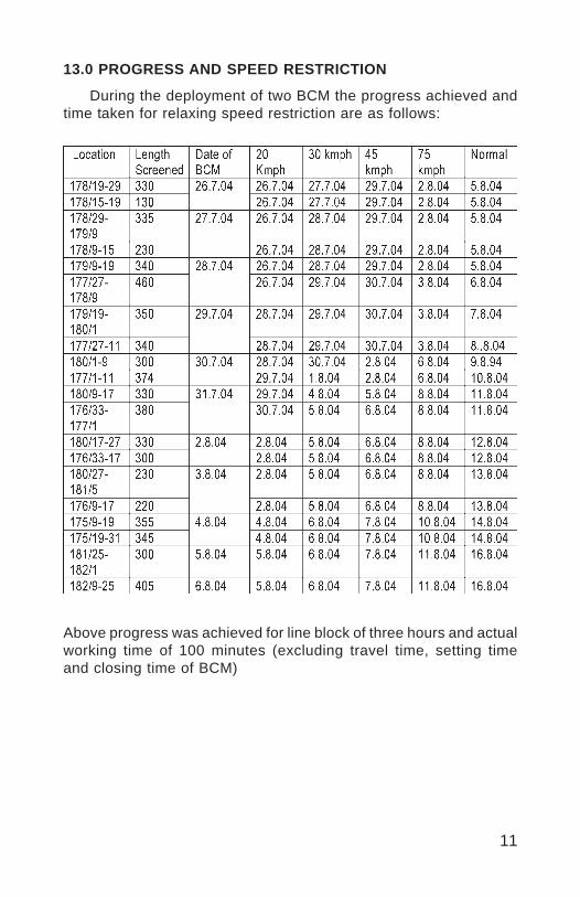
13.0 PROGRESS AND SPEED RESTRICTION
During the deployment of two BCM the progress achieved andtime taken for relaxing speed restriction are as follows:
Above progress was achieved for line block of three hours and actualworking time of 100 minutes (excluding travel time, setting timeand closing time of BCM)
12
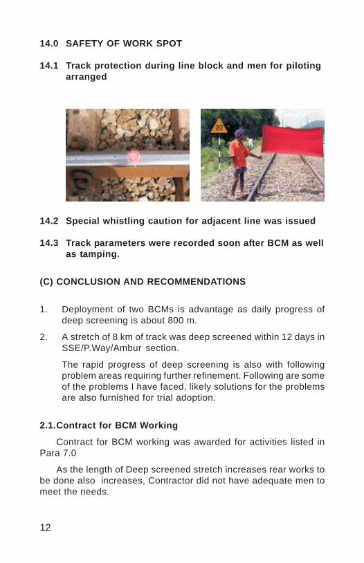
14.0 SAFETY OF WORK SPOT
14.1 Track protection during line block and men for pilotingarranged
14.2 Special whistling caution for adjacent line was issued
14.3 Track parameters were recorded soon after BCM as wellas tamping.
(C) CONCLUSION AND RECOMMENDATIONS
1. Deployment of two BCMs is advantage as daily progress ofdeep screening is about 800 m.
2. A stretch of 8 km of track was deep screened within 12 days inSSE/P.Way/Ambur section.
The rapid progress of deep screening is also with followingproblem areas requiring further refinement. Following are someof the problems I have faced, likely solutions for the problemsare also furnished for trial adoption.
2.1.Contract for BCM Working
Contract for BCM working was awarded for activities listed inPara 7.0
As the length of Deep screened stretch increases rear works tobe done also increases, Contractor did not have adequate men tomeet the needs.
13
The normal process of termination of contract does not work forline block activities, as termination of contract will affect BCMworking.
To tackle such a situation the probability of selecting twocontractors for track works can be considered. If L1 & L2contractor are selected in case of failure of L1 contractor,L2 contractor can be deployed to take up the left out works.
There can be a special condition stating that in case of failureof L1 contractor during the execution of work the work will begot done by L2 contractor at short notice, risk amount will berecovered from L1 contractor, so that progress of works will notbe affected on grounds of termination and risk tender procedures.Currency of L1 & L2 contractors will be same. Agreement forL2 contractor to be drawn duly mentioning that he is wait listedcontractor and shall be ready to take up the work at short noticeduring the currency period.
2.2.Execution of Welding Works
Presently SKV welding needs are met through two ways.
Track welding contract executed by portion manufacturing firmitself.
SKV Welding done by departmental authorized welders withportions supplied to railways by manufacturer.
For works like BCM number of joints to be welded is about 10welds for each km of track. As need for welding is less it is difficultto fix track welding contract executed by portion manufacturingfirm. Hence welding needs are met by SKV Welding done bydepartmental authorized welders with portions supplied to railwaysby manufacturer.
Problems faced in this type of welding are that it is difficult toensure quality of consumables including portions. Added to thisproblem due to the practice of first in first out method older portionsand consumables are sent to welding works, keeping new supplyintact.
Present method of first in first out is a serious threat to qualitywelds due to prolonged storage of consumables including portion.
14
To over come this problem we can try execution of weldingworks through works contractor, with portion and consumablespurchased from authorized manufacturers by works contractorhimself duly hiring qualified staff from portion manufacturer orrailways, so that fresh portions and consumables can be usedfor work and long storage of welding portions by field officialscan be avoided.
2.3 Transporting Diesel from P.Way Depot to Work Spots
Presently diesel for the requirements of track machine istransported from P.Way depot to base depot by zonal contractagreements. There is also loss of diesel during transit due to spillageand leakage.
To over come this problem the probability of fixing contractorfor transporting diesel from oil Company to various base depotsof division on demand can be considered.
2.4 Screening of Ballast left out by BCM on Shoulder Side:
Instead of the method of screening the ballast left by BCM onshoulder side manually under the contract, provisions may bemade for removing the ballast from shoulder and putting intocenter of track before actual BCM work as a pre-block activity
Alternatively BRM can be made as one of the machines workingalongwith BCM
Vinod
Placed Image

1
PLANNING & DEPLOYMENT OF TRACK MACHINES.
RAJESH AGARWAL*
SYNOPSIS
The perennial problems of vacancies of Gang Men and theircontinuously increasing age profile is leading to reduction in efficiencyof manual maintenance of track. The track structure has becomeheavier. The deployment of track machines has become inevitable.The amalgamation of Track Machines Organization with open lineP.Way set-up and their co-herent working has become the need ofthe time. Proper infrastructure for repair of Track Machines, basicneeds of Track machine staff and maintaining their motivation levelare of utmost impotence for achieving high productivity. This papertouches upon various factors, which have helped in achieving theabove goal.
1.0 INTRODUCTION
The introduction of Track Machines has helped to maintain thetrack geometry. The machine organization has been developed as aseparate setup within engineering department. The cadre of staff uptosupervisory level is deferent. This is necessary due to expertiserequired for operating and maintenance of machine. These machineshave to maintain the track structure. This track structure is directlyunder the control of P.Way supervisor. Hence, there are two streamsof staff working for the common goal. At times the disputes betweenthe two organizations are inevitable. These problems have to be keptunder check by proper management at higher levels.
2.0 CONVENTIONAL MAINTENANCE & TRACK STRUCTURE
The problems with manual maintenance system adopted in thepast are well known. The role of this manual maintenance has changed.This manual maintenance of track depends upon availability andphysical ability of Gangmen. The ban on recruitment of men power formany years has withered away the manual maintenance gangs.
*Sr. Divisional Engineer (HQ), Western Railway, RATLAM
2
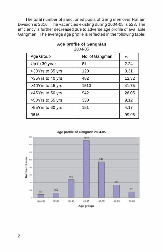
The total number of sanctioned posts of Gang men over RatlamDivision is 3616. The vacancies existing during 2004-05 is 528. Theefficiency is further decreased due to adverse age profile of availableGangmen. The average age profile is reflected in the following table:
Age profile of Gangman2004-05
Age Group No. of Gangman %
Up to 30 year 81 2.24
>30Yrs to 35 yrs 120 3.31
>35Yrs to 40 yrs 482 13.32
>40Yrs to 45 yrs 1510 41.75
>45Yrs to 50 yrs 942 26.05
>50Yrs to 55 yrs 330 9.12
>55Yrs to 60 yrs 151 4.17
3616 99.96
3
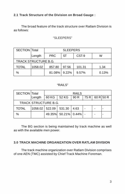
2.1 Track Structure of the Division on Broad Gauge :
The broad feature of the track structure over Ratlam Division isas follows:
“SLEEPERS”
SECTION Total SLEEPERS
Length PRC ST CST-9 W
TRACK STRUCTURE B.G.
TOTAL 1058.02 857.80 97.56 101.31 1.34
% 81.08% 9.22% 9.57% 0.13%
“RAILS”
SECTION Total RAILSLength 60 KG 52 KG 90 R 75 R 60 R 50 R
TRACK STRUCTURE B.G.
TOTAL 1058.02 522.09 531.30 4.63 - - -
% 49.35% 50.21% 0.44% - - -
The BG section is being maintained by track machine as wellas with the available men power.
3.0 TRACK MACHINE ORGANIZATION OVER RATLAM DIVISION
The track machine organization over Ratlam Division comprisesof one AEN (TMC) assisted by Chief Track Machine Foreman.
4
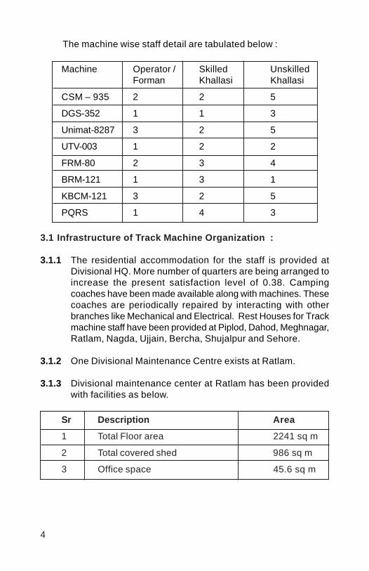
The machine wise staff detail are tabulated below :
Machine Operator / Skilled UnskilledForman Khallasi Khallasi
CSM – 935 2 2 5
DGS-352 1 1 3
Unimat-8287 3 2 5
UTV-003 1 2 2
FRM-80 2 3 4
BRM-121 1 3 1
KBCM-121 3 2 5
PQRS 1 4 3
3.1 Infrastructure of Track Machine Organization :
3.1.1 The residential accommodation for the staff is provided atDivisional HQ. More number of quarters are being arranged toincrease the present satisfaction level of 0.38. Campingcoaches have been made available along with machines. Thesecoaches are periodically repaired by interacting with otherbranches like Mechanical and Electrical. Rest Houses for Trackmachine staff have been provided at Piplod, Dahod, Meghnagar,Ratlam, Nagda, Ujjain, Bercha, Shujalpur and Sehore.
3.1.2 One Divisional Maintenance Centre exists at Ratlam.
3.1.3 Divisional maintenance center at Ratlam has been providedwith facilities as below.
Sr Description Area
1 Total Floor area 2241 sq m
2 Total covered shed 986 sq m
3 Office space 45.6 sq m
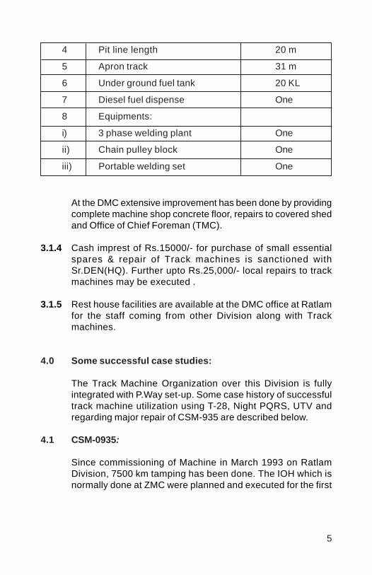
5
4 Pit line length 20 m
5 Apron track 31 m
6 Under ground fuel tank 20 KL
7 Diesel fuel dispense One
8 Equipments:
i) 3 phase welding plant One
ii) Chain pulley block One
iii) Portable welding set One
At the DMC extensive improvement has been done by providingcomplete machine shop concrete floor, repairs to covered shedand Office of Chief Foreman (TMC).
3.1.4 Cash imprest of Rs.15000/- for purchase of small essentialspares & repair of Track machines is sanctioned withSr.DEN(HQ). Further upto Rs.25,000/- local repairs to trackmachines may be executed .
3.1.5 Rest house facilities are available at the DMC office at Ratlamfor the staff coming from other Division along with Trackmachines.
4.0 Some successful case studies:
The Track Machine Organization over this Division is fullyintegrated with P.Way set-up. Some case history of successfultrack machine utilization using T-28, Night PQRS, UTV andregarding major repair of CSM-935 are described below.
4.1 CSM-0935:
Since commissioning of Machine in March 1993 on RatlamDivision, 7500 km tamping has been done. The IOH which isnormally done at ZMC were planned and executed for the first
6
time on Western Railway in any DMC at Ratlam. Followingmain repairing works were performed:
i) Replacement of Tamping bank.
ii) Replacement of Machine Engine
iii) Reconditioning of Important accessories like lifting unit,Satellite beam, Bogie wheels & feeler rods etc.
iv) Cleaning and pressure testing of hydraulic oil coolers andEngine radiator.
v) Recharging of hydraulic equmelator by N2 gas and refittingthe same.
vi) Replacement of Hydraulic and pneumatic hoses.
vii) Complete painting of the machine.
All these above works were carried out with limited resourcesand within a very short time that is of 10 days. The failure rates of thismachine have decreased. The time that would have been lost inmovement of machine to and fro Ratlam and ZMC at Valsad was alsosaved. The Performance of machine during last four years is as follows:
Year 2000-01 2001-02 2002-03 2003-04
Tamping done in km 731 902 945 927
4.2 Point & Crossing laying Machine (T-28)
Ratlam Division used one set (2 Nos.) of T-28 machine during2003-04 and 64 turnouts were laid. The machine was used in differentmanner for switch laying, complete turnout laying, simultaneous twoswitch laying etc. during day and night traffic blocks depending uponthe site condition.
Working of machine required preparation and preliminaryarrangement for smooth execution and proper laying. Some importantpoints are as under:
i) Selection of location for out side linking of switch/turnoutaccording to feasibility for T-28 machine working,transportation of switch/turnout to be replaced etc.
ii) Unloading of PRC sleepers, switch and crossing at properplace.
7
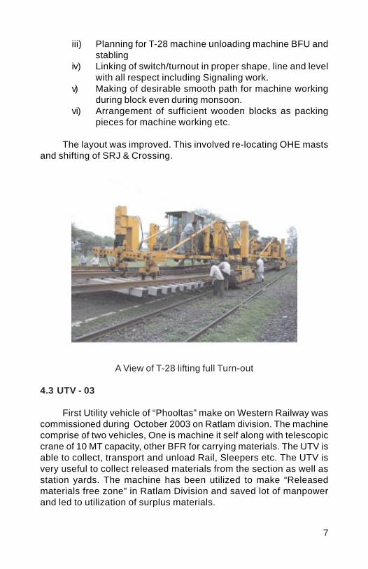
iii) Planning for T-28 machine unloading machine BFU andstabling
iv) Linking of switch/turnout in proper shape, line and levelwith all respect including Signaling work.
v) Making of desirable smooth path for machine workingduring block even during monsoon.
vi) Arrangement of sufficient wooden blocks as packingpieces for machine working etc.
The layout was improved. This involved re-locating OHE mastsand shifting of SRJ & Crossing.
A View of T-28 lifting full Turn-out
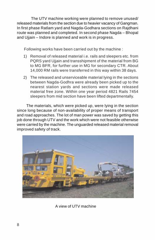
4.3 UTV - 03
First Utility vehicle of “Phooltas” make on Western Railway wascommissioned during October 2003 on Ratlam division. The machinecomprise of two vehicles, One is machine it self along with telescopiccrane of 10 MT capacity, other BFR for carrying materials. The UTV isable to collect, transport and unload Rail, Sleepers etc. The UTV isvery useful to collect released materials from the section as well asstation yards. The machine has been utilized to make “Releasedmaterials free zone” in Ratlam Division and saved lot of manpowerand led to utilization of surplus materials.
8
The UTV machine working were planned to remove unused/released materials from the section due to heavier vacancy of Gangman.In first phase Ratlam yard and Nagda-Godhara sections on Rajdhaniroute was planned and completed. In second phase Nagda – Bhopaland Ujjain – Indore is planned and work is in progress.
Following works have been carried out by the machine :
1) Removal of released material i.e. rails and sleepers etc. fromPQRS yard Ujjain and transshipment of the material from BGto MG BFR, for further use in MG for secondary CTR. About14,000 RM rails were transferred in this way within 38 days.
2) The released and unserviceable material lying in the sectionsbetween Nagda-Godhra were already been picked up to thenearest station yards and sections were made releasedmaterial free zone. Within one year period 4821 Rails 7454sleepers from mid section have been lifted departmentally.
The materials, which were picked up, were lying in the sectionsince long because of non-availability of proper means of transportand road approaches. The lot of man power was saved by getting thisjob done through UTV and the work which were not feasible otherwisewere carried by the machine. The unguarded released material removalimproved safety of track.
A view of UTV machine

9
4.4 PQRS Night working
In Ratlam-Nagda and Ujjain-Bhopal section primary renewals ofPSC 52 Kg. Track with 60 Kg. PSC were sanctioned and in Ujjain-Dewas-Indore (IDU) secondary TSR with released 52 kg PSC sleeperswere sanctioned. Both the renewals were planned simultaneously withPQRS. The released panels of the primary CTR track were planned tobe used directly on the secondary CTR locations through PQRSworking at both the place. In IDU section even a two hours trafficblock is not possible in day time due to heavy rush of passengertrains. Hence, night working of PQRS was the only option. Planningof the work was as under:
(1) PQRS working on Primary renewal site in day and secondaryrenewal site in night were planned. The PQRS rake in as it iscondition from primary renewal site was planned to be shifteddirectly to the secondary renewal site.
(2) At secondary renewal site only PQRS working was plannedin night and other preparatory and post works were plannedin day time.
(3) For night working of PQRS sufficient lighting arrangementwith four sets of generators, eight high power halogen lamps,along with one complete as spare were planned. One portablelight set for portals movement was also planned.
32 km secondary TSR was executed through night working ofPQRS successfully in IDU section of Ratlam division. While executionof the night working of PQRS following activities were monitoredvigorously.
i) Working of different groups of machine staff, P. waysupervisor and contractor supervisors & labour.
ii) Movement of rake
iii) Site preparation for day and night work.
iv) PQRS yard working.v) P. way material feeding.
(4) Movement of the rake was planned on the same day to thesecondary site for night PQRS working. Second day rake wasplanned for unloading of secondary released materials andloading of new panels for primary CTR. This way for day and

10
night PQRS two day blocks and two night blocks each weekwere planned and executed. The direct use of primary siterelease track panels saved lot of activities and hence savedlot of revenue
5.0 THE FINAL RESULT
5.1 The improvements effected thro’ better management of Trackmachine has ultimately resulted in maintaining the trackgeometry to a good level of acceptability. The 3 year TGI valuesof Rajdhani route over the division are as follows:
Comparative TRC result for last 3 years on GDA-Ratlam-NADSection
Section Line Sept’ 2002 Sept’ 2003 Sept’ 2004
TGI CTR TGI CTR TGI CTR
DIVISION DN 102 89 94 77 97 82
UP 98 84 95 80 106 88
5.2 The successful utilization of T-28 has enabled provision of Fan-shaped PRC layouts at all way-side stations on Rajdhani route.The panel interlocking on Indore-Dewas-Ujjain section could becompleted using T-28 for laying PRC turnouts. The sectionalspeed is now increased from 75 KMPH to 100 KMPH in singleline section.
5.3 The scattered material lying on the cess has been removedincreasing the safety from miscreants. The same material hasbeen used for yards and MG sections in secondary works.
5.4 The continued PQRS has helped in completing the scope ofPQRS in Ratlam division. Now, according to feasibility, CTRthrough PQRS of loop lines of the stations is being done.

11
6.0 CONCLUSION
The management problem of integrated work involving trackmachine organization and P.way staff needs human touch andarrangement of basic needs of TMC. Once these items are takencare of, the desired result automatically pour in. The time spent inimproving the facilities is worth and is better utilized than time spentin fire fighting. The enhanced productivity and low failure rates areproof in themselves for above premise.
Vinod
Placed Image
1
ROLE OF SMALL TRACK MACHINES INCONSTRUCTION OF TRACK
NARENDER KUMAR*B.P.AWASTHI*
SYNOPSIS
Due to growing traffic and introduction of heavier track structures,faster and more efficient methods of track maintenance andconstruction are needed to be evolved. Track relaying/constructionby TRT, PQRS involves huge investment and these machines arecostly assets. There is a wide gap between manual construction andrelaying/construction of track by TRTs/PQRS. Though relaying/construction is not desirable by manual means, better quality andprogress of track construction can be achieved if Small TrackMachines are extensively used on construction/relaying projects. Theuse of Small Track Machines is quite economical and is essential forquality and safety as well.
1.0 GENERAL
In the changed socio-economic scenario, role of Small TrackMachines has increased for quality maintenance and construction oftrack. Thirty three types of Small Track Machines have been developedon Indian Railways. These Small Track Machines/tools can beeffectively used for day to day maintenance, laying and constructionof track, thereby reducing the manual labour content.
Objective of this paper is
To bring out the causes of poor usage of Small Machines,
Action to be taken for improving the present position,
To introduce the P-Way engineers to some of the Small TrackMachines which can be extensively used to achieve betterquality / progress of track construction.
To evaluate economy in usage of small track machines.
* Director/Track Machine
2
Introduction of these machines would help in development of skilled/semi-skilled labour, availability of which will be better than unskilledlabour presently being employed by the contractors on trackconstructionprojects. This will reduce the dependence on unskilledlabour.
1.1 Causes of Poor Usage of Small Machines
Poor acceptability of small track machines in field is caused byso many factors. Experience of IR personnel on Small Track Machinesis limited due to:
a) No or improper training,b) Non-availability of proper system of procurement of
consumables.c) No facility for transportation of small machines andd) Improper maintenance system.e) Human nature of non accepting a new practice over an old one.
1.2 Action to be taken for Improving the Present Position:
Following immediate steps must be taken to overcome the abovefactors:
a) Designing system for procurement of Small Machines and theirconsumables.
b) Proper training at the time of supply of machine.c) Practical solution for transportation of man and small machine.d) Proper maintenance system.
All railways have been instructed to compulsorily arrangetraining by the manufacturer at the time of supply of machines. Apositive step has already been taken by introduction of small trackmachine manual which is under approval. The manual will addressthe other problems by evolving a system of procurement of machinesconsumables and their maintenance. The problem of transportationof Small Machines is being tackled through development of Rail cumRoad Vehicle, which is under trial. Other alternatives available on worldrailways are also needed to be looked into. Contractors doing thetrack construction work can also be asked to procure and deploySmall Track Machines for all activities which can be mechanized.Railway Board vide letter no. 2003/Track-III/TK/6 dated 06-08-2003has circulated the accepted recommendation of committee on use ofSmall Track Machines elaborating guidelines regarding conditions for
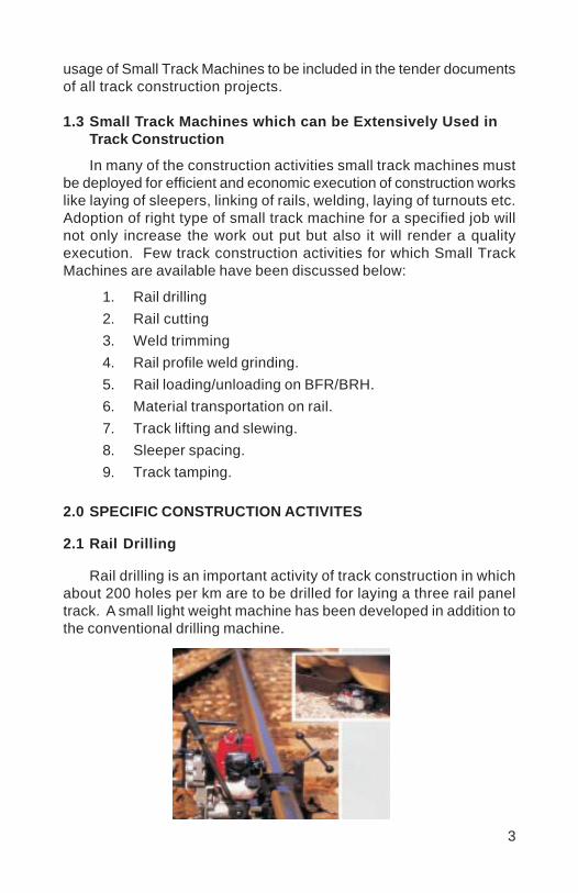
3
usage of Small Track Machines to be included in the tender documentsof all track construction projects.
1.3 Small Track Machines which can be Extensively Used inTrack Construction
In many of the construction activities small track machines mustbe deployed for efficient and economic execution of construction workslike laying of sleepers, linking of rails, welding, laying of turnouts etc.Adoption of right type of small track machine for a specified job willnot only increase the work out put but also it will render a qualityexecution. Few track construction activities for which Small TrackMachines are available have been discussed below:
1. Rail drilling2. Rail cutting3. Weld trimming4. Rail profile weld grinding.5. Rail loading/unloading on BFR/BRH.6. Material transportation on rail.7. Track lifting and slewing.8. Sleeper spacing.9. Track tamping.
2.0 SPECIFIC CONSTRUCTION ACTIVITES
2.1 Rail Drilling
Rail drilling is an important activity of track construction in whichabout 200 holes per km are to be drilled for laying a three rail paneltrack. A small light weight machine has been developed in addition tothe conventional drilling machine.

4
This machine makes hole by cutting only the perimeter of thehole (core cutting) rather than cutting and removing complete materialof the hole (Conventional drilling). Power pack is a two stroke, petroldriven engine or single phase, electric driven engine. Holes are madewith broach cutters of desired diameter. The time taken to drill a holein the web of 60 kg 90 UTS rail is about 30-40 seconds, weight of themachine is less than 20 kg. Machine is a bit costly as presently it isbeing imported. Only one man is required for its transportation /handling/lifting and drilling holes as against 3-4 persons for an ordinarymechanized drilling machine weighing about 65 kg. So cost recoveryis quite fast due to saving in manpower.
2.2. Rail Cutting
Rail cutting becomes an important construction activity wheresecond hand released rails are used.
Two types of machines are in use, namely, (i) Saw type and (ii)Disc type.
2.2.1 Saw type rail cutting machine
Saw type rail cutting machine is an engine driven sawing machineweighing upto 70 kg and can give a perfect cut in rails of any sectionfrom 60 R to 60 kg section. The engine is air cooled, petrol start andkerosene run having 2 to 3 HP rating at 3000 to 4000 rpm. The timetaken to cut a rail section depends upon the rail metallurgy and bladequality and ranges from 10 min to 20 min. The machine can easily behandled by two men (one skilled and one unskilled). The machinecan be rolled to the work spot either on cess or on rail by the wheelsfitted to the trolley of the machine.
The machine is economical for track construction works as it canwork continuously.
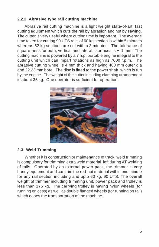
5
2.2.2 Abrasive type rail cutting machine
Abrasive rail cutting machine is a light weight state-of-art, fastcutting equipment which cuts the rail by abrasion and not by sawing.The cutter is very useful where cutting time is important. The averagetime taken for cutting 90 UTS rails of 60 kg section is within 5 minuteswhereas 52 kg sections are cut within 3 minutes. The tolerance ofsquare-ness for both, vertical and lateral, surfaces is + 1 mm. Thecutting machine is powered by a 7 h.p. portable engine integral to thecutting unit which can impart rotations as high as 7000 r.p.m. Theabrasive cutting wheel is 4 mm thick and having 400 mm outer diaand 22.23 mm bore. The disc is fitted to the power shaft, which is runby the engine. The weight of the cutter including clamping arrangementis about 35 kg. One operator is sufficient for operation.
2.3. Weld Trimming
Whether it is construction or maintenance of track, weld trimmingis compulsory for trimming extra weld material left during AT weldingof rails. Operated by an external power pack, the trimmer is veryhandy equipment and can trim the red-hot material within one minutefor any rail section including and upto 60 kg, 90 UTS. The overallweight of trimmer including trimming unit, power pack and trolley isless than 175 kg. The carrying trolley is having nylon wheels (forrunning on cess) as well as double flanged wheels (for running on rail)which eases the transportation of the machine.

6
The power pack unit comprises of a hydraulic pump (withdirectional controls) coupled with an air cooled petrol / diesel enginehaving minimum continuous rating of 3 HP. The weld trimmer is easilyhandled by two men (one skilled and one unskilled).
2.4.Rail Profile Weld Grinding
The finishing of rail weld after trimming is efficiently done by railprofile weld grinder. The rail profile weld grinder is a compact grindingmachine powered by an in-built air cooled engine (petrol start, kerosenerun) / electric motor and total weight is within 80 kg. Electricallydriven grinder weighs only 33 kg. Cup-shaped grinding stones areused to grind the weld profile and the machine has top and side guiderollers, which enable the grinder to tilt upto 900 deflection for grindingtop and faces of the rail head. For operation of the machine one manis sufficient. Grinding time is about 15 minutes, which depends uponthe quantity of left over material after trimming.
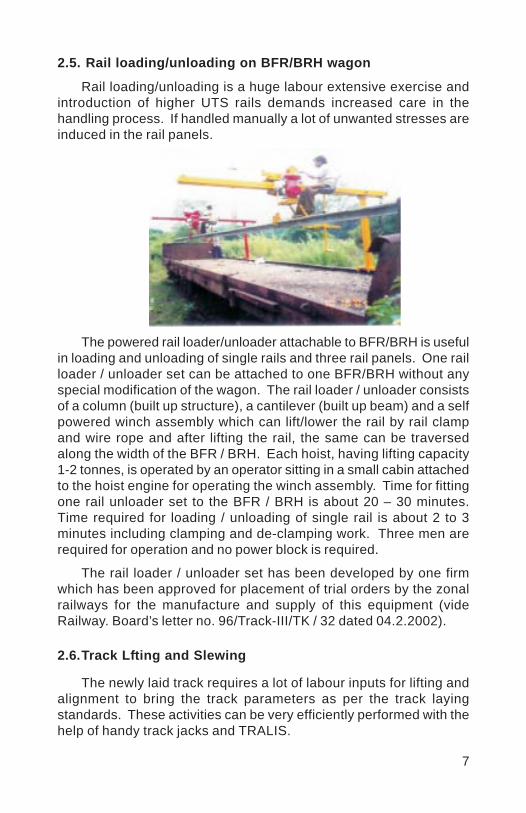
7
2.5. Rail loading/unloading on BFR/BRH wagon
Rail loading/unloading is a huge labour extensive exercise andintroduction of higher UTS rails demands increased care in thehandling process. If handled manually a lot of unwanted stresses areinduced in the rail panels.
The powered rail loader/unloader attachable to BFR/BRH is usefulin loading and unloading of single rails and three rail panels. One railloader / unloader set can be attached to one BFR/BRH without anyspecial modification of the wagon. The rail loader / unloader consistsof a column (built up structure), a cantilever (built up beam) and a selfpowered winch assembly which can lift/lower the rail by rail clampand wire rope and after lifting the rail, the same can be traversedalong the width of the BFR / BRH. Each hoist, having lifting capacity1-2 tonnes, is operated by an operator sitting in a small cabin attachedto the hoist engine for operating the winch assembly. Time for fittingone rail unloader set to the BFR / BRH is about 20 – 30 minutes.Time required for loading / unloading of single rail is about 2 to 3minutes including clamping and de-clamping work. Three men arerequired for operation and no power block is required.
The rail loader / unloader set has been developed by one firmwhich has been approved for placement of trial orders by the zonalrailways for the manufacture and supply of this equipment (videRailway. Board’s letter no. 96/Track-III/TK / 32 dated 04.2.2002).
2.6.Track Lfting and Slewing
The newly laid track requires a lot of labour inputs for lifting andalignment to bring the track parameters as per the track layingstandards. These activities can be very efficiently performed with thehelp of handy track jacks and TRALIS.

8
2.6.1 Hydraulic track jack
Hydraulic track jack is a very handy and simple hydraulicequipment for lifting track upto 80 mm at a stretch. The weight isonly 13.5 kg (maximum) and is easy to operate and handle. It can lifta load upto 15 tonnes vertically with maximum close height is 166mm + 3 mm. It can easily be handled by one man. The jack is non-infringing type and can be released instantaneously on the face of anapproaching train.
2.6.2 Hydraulic track lifting-cum-slewing device (TRALIS)
Lifting and slewing of track can simultaneously be done withthis equipment. TRALIS is a hydraulic equipment and comprisesof one lifting and one slewing jack (double acting) fixed together.The jack assembly is operated by an external hand pump. Thedirectional control of the hydraulic oil is also actuated throughD.C. valves attached as integral part of the pump. The vertical liftof the jack is 80 mm with 10 t load whereas capacity of horizontaljack is 5 t and it can traverse upto 100 mm (50 mm on eitherside). Overall weight of the equipment is within 60 kg. Theequipment can easily be handled by two men.

9
Now a 15T higher version of TRALIS has been developed and isunder trial order; The salient features are:
Vertical lift : 120 mmHorizontal traverse : 150 mm on either sideVertical jack capacity : 15 tHorizontal jack capacity : 7.5 tThis higher version is more suitable for construction projects.
2.7. Transportation of Material on Rails
A newly developed self propelled light weight trolley with traileris very useful for construction sites for carrying small track machinesand P.Way materials like fittings & fastenings etc. Overall weight ofthe system is 330 kg (160 kg + 170 kg trolley) and payload capacityis 1000kg (trailer – 700 kg + trolley 300 kg). The trolley, powered bypetrol/diesel engine is having seating capacity for five persons (front3 + rear-2) and can run at a speed upto 20 km/h. One manufacturerhas been approved by Railway Board for trial of this trolley with trailerby railways. The trolley can be lifted by four men.
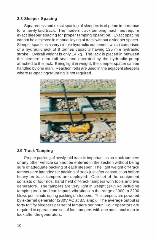
10
2.8 Sleeper Spacing
Squareness and exact spacing of sleepers is of prime importancefor a newly laid track. The modern track tamping machines requireexact sleeper spacing for proper tamping operation. Exact spacingcannot be achieved in manual laying of track without a sleeper spacer.Sleeper spacer is a very simple hydraulic equipment which comprisesof a hydraulic jack of 8 tonnes capacity having 125 mm hydraulicstroke. Overall weight is only 14 kg. The jack is placed in betweenthe sleepers near rail seat and operated by the hydraulic pumpattached to the jack. Being light in weight, the sleeper spacer can behandled by one man. Reaction rods are used in the adjacent sleeperswhere re-spacing/squaring is not required.
2.9 Track Tamping
Proper packing of newly laid track is important as on-track tampersor any other vehicle can not be entered in the section without beingsure of adequate packing of each sleeper. The light weight off-tracktampers are intended for packing of track just after construction beforeheavy on track tampers are deployed. One set of the equipmentconsists of four nos. hand held off-track tampers with tools and twogenerators. The tampers are very light in weight (14.5 kg includingtamping tool) and can impart vibrations in the range of 900 to 2200blows per minute during packing of sleepers. The tampers are poweredby external generator (230V AC at 8.5 amp). The average output isforty to fifty sleepers per set of tampers per hour. Four operators arerequired to operate one set of four tampers with one additional man tolook after the generators.

11
2.10 Activities performed by common power pack
Presently, emphasis is on development of one common powerpack for all the machines which usually perform at a work site.Electrically driven Rail drilling, Rail cutting, weld trimming and Railprofile grinding machines with a common power pack for welding siteshave already been developed. For the same activities hydraulicmachines with a hydraulic common power pack are being developedfor Indian Railways.
3.0 ECONOMICS OF SMALL TRACK MACHINES
Per unit cost has been calculated for each activity discussedabove and has been compared with manual unit cost of the activityand has been tabulated below. It clearly reveals that inspite of initialcost investment in Small Tack Machines, the unit cost of each activityis cheaper if mechanized, as compared to manual cost. And aboveall quality of work output is much superior.
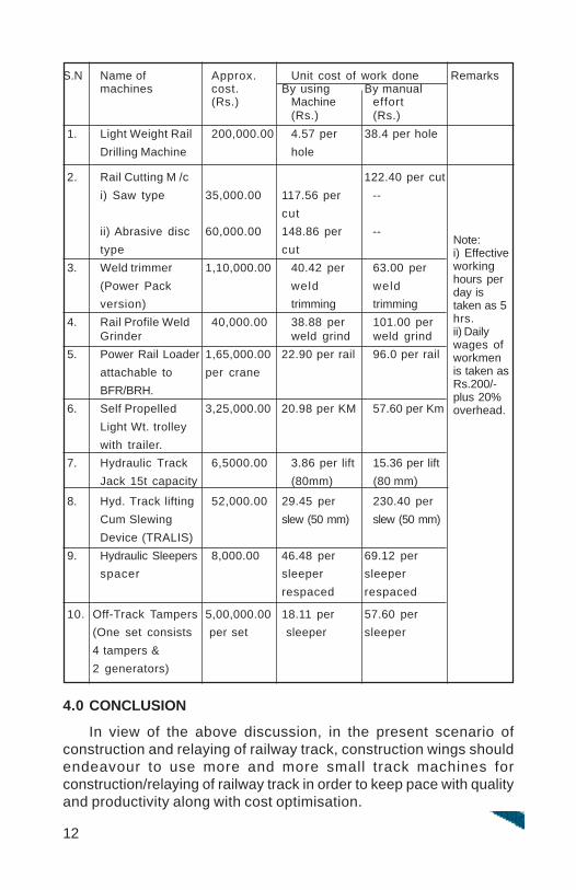
12
S.N Name of Approx. Unit cost of work done Remarksmachines cost. By using By manual
(Rs.) Machine effort(Rs.) (Rs.)
1. Light Weight Rail 200,000.00 4.57 per 38.4 per holeDrilling Machine hole
2. Rail Cutting M /c 122.40 per cuti) Saw type 35,000.00 117.56 per --
cutii) Abrasive disc 60,000.00 148.86 per --type cut
3. Weld trimmer 1,10,000.00 40.42 per 63.00 per(Power Pack weld weldversion) trimming trimming
4. Rail Profile Weld 40,000.00 38.88 per 101.00 perGrinder weld grind weld grind
5. Power Rail Loader 1,65,000.00 22.90 per rail 96.0 per railattachable to per craneBFR/BRH.
6. Self Propelled 3,25,000.00 20.98 per KM 57.60 per KmLight Wt. trolleywith trailer.
7. Hydraulic Track 6,5000.00 3.86 per lift 15.36 per liftJack 15t capacity (80mm) (80 mm)
8. Hyd. Track lifting 52,000.00 29.45 per 230.40 perCum Slewing slew (50 mm) slew (50 mm)Device (TRALIS)
9. Hydraulic Sleepers 8,000.00 46.48 per 69.12 perspacer sleeper sleeper
respaced respaced
10. Off-Track Tampers 5,00,000.00 18.11 per 57.60 per(One set consists per set sleeper sleeper4 tampers &2 generators)
4.0 CONCLUSION
In view of the above discussion, in the present scenario ofconstruction and relaying of railway track, construction wings shouldendeavour to use more and more small track machines forconstruction/relaying of railway track in order to keep pace with qualityand productivity along with cost optimisation.
Note:i) Effectiveworkinghours perday istaken as 5hrs.ii) Dailywages ofworkmenis taken asRs.200/-plus 20%overhead.
Vinod
Placed Image

1
PLANNING, UTILIZATION AND PERFORMANCE OFON-TRACK MACHINE ON INDIAN RAILWAY
S.K.SINGH*D.S.PRAJAPATI**
SYNOPSIS
On Track machine is a costly sophisticated but effective systemof track maintenance for modern track structure. Now it has a greatimportance for track Engineers. Proper and meticulous planning fordeployment of track machines, its proper utilization can result betterperformance of the machines and thereby a good quality of trackstandards. There are no. of problems related to effective utilizationof the track machine. In this paper effort has been made to explorevarious ways and means for effective planning, utilization and ensurebetter qualitative output by on track machines.
1.0 INTRODUCTION
Indian Railway is the largest means of transportation managed bya single management in the world. With the use of heavier trackstructure, increased sleeper density, enhanced train speed and trafficdensity, the time for track maintenance is reducing rapidly day byday. Traffic density which was 7.45 million units in 1970-71 has nowincreased to 16.85 million units in 2001-02. Meaning thereby, thework which is presently being done by means of manual method hasto be done by the track machines that too in lesser time. Moreovernumber of staff which was 15.453 lakhs in 2001-02 has been reducedto 14.719 in 2002-03. Therefore no any option is left except to go formechanised maintenance. On Indian Railway there are two types oftrack machine
a) Large/On-track machineb) Small Track Machine
Since on Track machine will be used only in traffic block, thereforeplanning utilization and its performance monitoring needs to be verycarefully examined during day to day working in the actual field.
* Assistant Research Engineer/TM , RDSO, Lucknow** Jr.Engineer/Engg-I/TM, RDSO, Lucknow
2
2.0 PLANNING FOR DEPLOYMENT OF MACHINE:
Working of all types of machines shall be managed and controlledby Zonal Railways at head quarter level. Based upon the maintenanceneeds, track renewable needs, availability of blocks, an annualrequirements of the machine shall be prepared taking into considerationrequirement of construction organization over Zonal Railway. Detailplanning shall be based on chapter-5 of Indian Railway track machinemanual –2000. Moreover following aspects must be taken intoconsideration while planning for deployment of track machines.
2.1 Base Depot LocationBase depot of the track machine shall be centrally located inthe section where actual work is to be carried out. It will reducethe transit time to /from work place. All basic facilities shall bemade available at the base depot location. A typical layout forbase depot shall be as per IRTM Manual – 2000.
2.2 Loco requirement and Loco Power availabilityThere are some machines which needs loco for working duringblock or for base depot work. While planning the requirement oftrack machine for a zonal railway, a MOU shall be signed amongengineering department and power control etc. at division/ headquarter level. This MOU shall be circulated to all divisions atthe time of circulating annual planning of on track machine. Anychange in MOU shall be approved by Divisional Railway Managerat the division level and by GM at zonal railway head quarterlevel. Proper co-ordination among the senior officers at division/headquarter level is required for proper control over such issues.
2.3 Block requirement and availabilityDepending upon previous year performance for different types oftrack machine work, block requirement shall be prepared fordifferent works. Availability of block shall be monitored effectivelyfor proper work output. Non availability of block or block refusalshall be viewed seriously. Post block work shall be properlywitnessed by a responsible official.
2.4 Necessity of BallastFoot by foot survey for ballast shortage shall be carried out bySE/P-way of each section and it should be verified by respectiveAEN of the section. At times, it is seen that quantity of ballastis not sufficient for proper working of track machines. In such
3
case speed restriction is to be imposed for want of ballast as atemporary measure. It may also cross the limit of the speedrestriction as per allowance given for engineering department atdivision level. Since ballast feeding takes a lot of time, thereforeindent for ballast shall be placed at proper time giving extramargin of time so that activities of track machine working is nothampered.
2.5 Speed Restrictions - While drafting the annual requirement ofdifferent track machine, engineering officials must have anexercise that speed restriction in his jurisdiction should notexceed the time frame allowed at division/head quarter level.Speed restriction chart shall be available with SE/P-way /AENlevel for ready reference.
2.6 Output of Individual Machine – After each block, output ofthe individual track machine shall be properly monitored at divisionlevel so that future requirement for deployment of machines canbe undertaken. Deployment of Gangs after work shall be ensuredas per requirement.
2.7 Effective availability of MachineEffective utilisation of machine shall be monitored properly takinginto account time allowance for periodical maintenance/ IOH/POH during that year for any particular track machine. Theproductivity and the utilization of machine is joint responsibilityof the division concerned as well as the track machineorganization. The role of track machine organization is to maketheir machine available in prefect working order for doing variousmaintenance work. The arrangement of traffic block and its properout put as well as effective utilization is the responsibility ofdivision concerned.
2.8 Priority/Target for completion of project/worksDepending upon the requirement given by the division andavailability of the machine, the priorities and targets shall befixed at the zonal head quarter level and annual deploymentprogramme of track machine shall be circulated to all divisionsin advance. All divisions should carefully plan the man power/consumables/etc. for proper utilization of machine during trafficblock. Once the programme of deployment of track machine isissued by headquarter, the division shall deploy the track machineaccordingly.
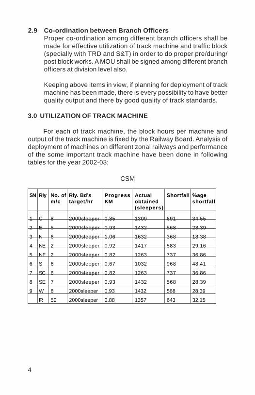
4
2.9 Co-ordination between Branch OfficersProper co-ordination among different branch officers shall bemade for effective utilization of track machine and traffic block(specially with TRD and S&T) in order to do proper pre/during/post block works. A MOU shall be signed among different branchofficers at division level also.
Keeping above items in view, if planning for deployment of trackmachine has been made, there is every possibility to have betterquality output and there by good quality of track standards.
3.0 UTILIZATION OF TRACK MACHINE
For each of track machine, the block hours per machine andoutput of the track machine is fixed by the Railway Board. Analysis ofdeployment of machines on different zonal railways and performanceof the some important track machine have been done in followingtables for the year 2002-03:
CSM
SN Rly No. of Rly. Bd’s Progress Actual Shortfall %agem/c target/hr KM obtained shortfall
(sleepers)
1 C 8 2000sleeper 0.85 1309 691 34.55
2 E 5 2000sleeper 0.93 1432 568 28.39
3 N 6 2000sleeper 1.06 1632 368 18.38
4 NE 2 2000sleeper 0.92 1417 583 29.16
5 NF 2 2000sleeper 0.82 1263 737 36.86
6 S 6 2000sleeper 0.67 1032 968 48.41
7 SC 6 2000sleeper 0.82 1263 737 36.86
8 SE 7 2000sleeper 0.93 1432 568 28.39
9 W 8 2000sleeper 0.93 1432 568 28.39
IR 50 2000sleeper 0.88 1357 643 32.15
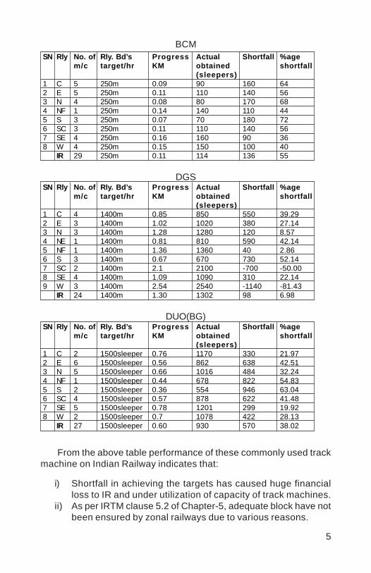
5
SN Rly No. of Rly. Bd’s Progress Actual Shortfall %agem/c target/hr KM obtained shortfall
(sleepers)1 C 5 250m 0.09 90 160 642 E 5 250m 0.11 110 140 563 N 4 250m 0.08 80 170 684 NF 1 250m 0.14 140 110 445 S 3 250m 0.07 70 180 726 SC 3 250m 0.11 110 140 567 SE 4 250m 0.16 160 90 368 W 4 250m 0.15 150 100 40
IR 29 250m 0.11 114 136 55
DGSSN Rly No. of Rly. Bd’s Progress Actual Shortfall %age
m/c target/hr KM obtained shortfall(sleepers)
1 C 4 1400m 0.85 850 550 39.292 E 3 1400m 1.02 1020 380 27.143 N 3 1400m 1.28 1280 120 8.574 NE 1 1400m 0.81 810 590 42.145 NF 1 1400m 1.36 1360 40 2.866 S 3 1400m 0.67 670 730 52.147 SC 2 1400m 2.1 2100 -700 -50.008 SE 4 1400m 1.09 1090 310 22.149 W 3 1400m 2.54 2540 -1140 -81.43
IR 24 1400m 1.30 1302 98 6.98
DUO(BG)SN Rly No. of Rly. Bd’s Progress Actual Shortfall %age
m/c target/hr KM obtained shortfall(sleepers)
1 C 2 1500sleeper 0.76 1170 330 21.972 E 6 1500sleeper 0.56 862 638 42.513 N 5 1500sleeper 0.66 1016 484 32.244 NF 1 1500sleeper 0.44 678 822 54.835 S 2 1500sleeper 0.36 554 946 63.046 SC 4 1500sleeper 0.57 878 622 41.487 SE 5 1500sleeper 0.78 1201 299 19.928 W 2 1500sleeper 0.7 1078 422 28.13
IR 27 1500sleeper 0.60 930 570 38.02
From the above table performance of these commonly used trackmachine on Indian Railway indicates that:
i) Shortfall in achieving the targets has caused huge financialloss to IR and under utilization of capacity of track machines.
ii) As per IRTM clause 5.2 of Chapter-5, adequate block have notbeen ensured by zonal railways due to various reasons.
BCM
6
iii) Poor performance of these important track machines may bedue to :
Optimal traffic block not granted.Lack of pre block works in the sections.Un-planned deployment of track machinesBrake down of the track machines
It is clear that all most all track machines are under utilisedcompared to target fixed by Railway Board. After analysis, it has beenfound that some measures are to be adopted to ensure the trafficblock as per IRTM. We must understand that traffic blocks are costlyfor railway system, hence a method is required to be evolved to ensurethe utilization of track machine in a most economical way.
4.0 PERFORMANCE OF TRACK MACHINES
Performance of the track machines will greatly depend upon theup-keep of the machine. Attention must be given to following aspectswhile carrying out the regular inspection of the machine by open lineofficials. These are necessarily required for getting best out put fromany track machine. Some following important aspect for commonlyused track machines shall be kept into consideration.
4.1 In case of Tamping Machines
Quality of pre tamping work.Squeezing pressure required for the workPSC sleeper 110-120 kg/cm2
ST sleeper 100-110 kg/cm2
CST 9 sleeper 90-100 kg/cm2
Vibration motor pressure.Condition of tamping tool.Setting of tamping depth.Squeezing time- 0.4 to 0.6 second.Track parameters after tamping.Out put of the machine.Proper functioning of brakes/horn/light.
7
4.2 In case of Ballast Cleaning Machines
Minimum 250 mm of ballast cushion (caked+clean).Obstruction by OHE and S&T department to be removed.Arrangement of proper quantity of ballast.Four hour traffic block for effective utilization of machine.Provision of LWR manual to be followed:All level crossing to be opened in advance.Gas cutting equipment to be made available on themachine.Complete and tight fittings to hold rail with sleeper.Proper functioning of brakes/horn/light.Proper ramp at start and closing at the time of day’s work.Depth of cut as per site condition.
4.3 In case of Dynamic Track Stabilizer
Frequency range to be selected within 32 to 37 Hz.Pressure variation range shall be 60-80 bar.Effective load range 230-290 KN.To be used after tamping machine work.Complete and tight fittings to hold rail with sleeper.Adequate quantity of track ballast.Working temperature of ZF Gear Box.Ensure proper functioning of brakes/horn/light.
5.0 Performance/productivity can be increased by getting work doneby any track machines with minimum expenditure on theoperation and maintenance of the track machine. Following pointneeds to be considered for improving the productivity:
i) Logical deployment/ suitable grouping of machines.ii) Availability of traffic block.iii) Reducing brake down time .iv) Timely spare parts management.v) Control over expenditure.vi) Technical competence and working environment.

8
vii) Welfare of officials working with track machines.viii) Providing Walkie-talkie set for easy communication with
engineering control.ix) Obeying proper maintenance schedule as per IRTM.x) Maintenance of brake down register with its remedial
measures.
6.0 CONCLUSION
On track machines are highly cost intensive but efficient meansfor maintenance of modern high speed track. IR should not purchaseany non-compatible machine. Its deployment should be logical andonly need based. We can not afford losses of traffic block and thesecostly machines since IR is investing crores of Rupees towards trackmachine for betterment of track. In order to ensure safety we shouldmake our track world class with proper understanding of need forprocurement, planning and deployment of track machines.
At last but not the least, a few points for consideration to all ofus for the sake of IR betterment are:
a) Are all the manuals made for accident enquiries only.b) Are we obeying the clauses of IRPWM/IRTM.c) Is traffic block is only responsible for poor out put of track
machine.d) Can we increase work out put of track machines.e) Do we need different types of machines for similar work.f) Requirement of separate control for engineering department
for all divisions is necessary.g) Do we need improvement in working atmosphere of tamping
machine officials.h) Are we doing justice to the work assigned to us.
Vinod
Placed Image
1
IMPROVING INHERENT TRACK QUALITYBY
IMPROVED METHOD OF BALLAST COMPACTION
R.K.VERMA*
SYNOPSIS
This paper brings out the shortcomings in the present practiceof ballast compaction on new lines/doublings and suggests animproved method, which would reduce track maintenance cost andgive a better ride. This applies to track renewal/deep screening sites,too.
1.0 INTRODUCTION:
Homogeneously compacted formation and ballast are importantfactors for the durability of the track geometry. While detailedspecifications for the compaction of the earthwork are available onthe Indian Railways (IR), no details are available for the compaction ofthe ballast bed. In the absence of such a specification, differentpractices of ballast compaction are being followed on zonal railways.
In this paper, the author has brought out the shortcomings in thepresent practice of ballast compaction, being followed on zonalrailways. He has also discussed the practice, being followed abroadand its advantages. Finally, the author has suggested the laying downof a detailed specification, on lines similar to the one being followedabroad. This will reduce the frequency of maintenance tamping, extendthe ballast life and ensure good ride.
2.0 INHERENT TRACK SHAPE:
It has been observed, that the track appears to have an inherentshape, which remains with it throughout its life. This inherent shapeappears to have been introduced into the track at the time of its originalconstruction. Achieving subsequent changes in this inherent shapeis very difficult. The reason for this shape is largely attributed to theshape of the rail and the profile of the supporting ballast bed.
* Sr. Professor, Indian Railways Institute of Civil Engineering, PUNE – 411 001
2
For short wavelengths of less than 5m, the stiffness of the railcompared to that of the ballast bed is high, resulting in, the rail,imprinting its shape onto the ballast bed. For longer wavelengths, thestiffness of the ballast bed is high compared to that of the rail, resultingin, the ballast bed, imprinting its shape onto the rail.
A comparison of the longitudinal rail levels of a track before routinemaintenance (i.e. tamping, levelling and lining) and subsequent to theroutine maintenance, after the passage of certain traffic, would indicatethat these profiles are virtually identical, i.e. the track inherits its presentgeometry from the long term geometry, associated with the previousmaintenance cycle.
3.0 INHERENT TRACK QUALITY
From the foregoing para, it also follows that the track has an‘Inherent Quality’. It has been observed that:
i) Track has an inherent quality, which is determined during theearly part of its life. It is a function of the quality of the componentsfrom which the track was constructed, as well as, the smoothnessand the compactness of the supporting ballast bed.
ii) Track having a good inherent quality requires little maintenanceand track having a poor inherent quality requires muchmaintenance.
Clearly, the two major factors responsible for the ‘Inherent Shape’,i.e. the shape of the rail and the profile of the supporting ballast bed,need special attention at the time of track construction. Rails shouldbe straight and the ballast bed should be free from longitudinal andcross level faults, as far as possible.
4.0 SHORTCOMINGS IN THE PRESENT PRACTICE OF BALLASTCOMPACTION
The general practice being followed by zonal railways is,compaction by a few passes of light rollers/material trains and tampingmachines. Such a method does not give a homogeneously compactedbed, as the compaction is carried out by crushing/squeezing action,which acts locally and also damages the stones. Even if vibratoryrollers are used, it is not effective, as explained in para 5. Therefore,subsequent loadings due to the traffic loads, cause uneven settlement
3
of the ballast bed, resulting in the development of long wavelengthfaults, in a short period. This requires correction by tamping machines,but, no matter how many times the track is tamped, it deteriorates,acquiring the same shape, i.e. the ‘Inherent Shape’, which is not gooddue to inhomogeneous compaction.
Another shortcoming is, inadequate compaction of crib/shoulderballast. This results in poor lateral stability of the track against thermalforces of LWR/CWR and lateral forces due to vehicles. This leads tothe development of lateral misalignments, which could be severe athigh speeds/on sharp curves.
5.0 IMPROVED METHOD:
The uniformity of compaction and the homogeneity of the ballastare of great importance because they have a considerable influenceon the uniformity of the remaining settlements and thus, the durabilityof the track geometry. This can be achieved by means of a dynamictrack stabiliser (DTS), which carries out force-free spatial (volumetric)compaction.
The tests carried out abroad reveal that ballast compaction withhorizontal oscillations is seven times more efficient than that withvertical oscillations. The DTS works on this principle. It vibrates thetrack in lateral direction combined with a vertical load for controlledsettlement. With the machine’s maximum vertical load of 240 kN,this produces a ballast compression of 0.08 N/mm2. This isconsiderably lower than the permissible ballast compression of around0.3 N/mm2. Therefore, the compacting effect of DTS is termed asforce-free spatial compaction. The ballast stones re-arrangethemselves more closely together and that, without any damage. Thecontact surfaces between the stones are much larger and morefrequent, as also, between the ballast and the sleepers.
The effectiveness of the compacting equipment decreases withdepth. This indicates the necessity of insertion of the ballast in layers.The ideal combination considered, is tamping and compaction by DTS,in layers of 70-100 mm thickness. Inhomogeneities of the ballast bedare shown up immediately by the DTS. Any inhomogeneities are, thensmoothened out by ballasting, tamping and compaction by DTS, inthe procedure for the next layer of ballast. Correct ballasting beforeevery tamping cycle is of course important.
4
On German Federal Railway’s high speed lines, ballastcompaction with the DTS is carried out with full vertical load (automaticlevelling device switched off) on the last but one tamping pass (toplayer of ballast). The following operating parameters are chosen:
120 kN vertical load/rail
33 Hz working frequency
1 km/h working speed.
On the last tamping pass with the residual lifts, the DTS is workedwith the automatic levelling device switched on. The working speed ofthe machine is raised to 1.2-2 km/h.
On the British Railways, the line is opened with a full speed of200 km/h after track renewal works, in a traffic block of 48 hrs., byadopting a similar method.
6.0 RECOMMENDATIONS:
Trials should be conducted on the IR to frame a detailedspecification for carrying out ballast compaction in layers, as describedbriefly above. When this specification will be adopted on new lines/doublings, track renewal/deep screening sites (depending on thefeasibility of traffic block), a track with good inherent quality will beproduced, which will need less maintenance and give a good ride.
Vinod
Placed Image

1
* President, M/s Harsco Track Technologies, USA
COMPLETE SWITCH MAINTENANCE
G. ROBERT NEWMAN*
SYNOPSIS
This paper is written to describe the newest and most efficienttechnologies for switch maintenance.
Complete maintenance of switches, crossovers, or points andcrossings includes grinding, ballast cleaning, and surfacing. Althoughmost mainline tampers now can surface a switch efficiently, grindingand ballast cleaning are essential elements of switch maintenancethat are often neglected. Efficient machines that can clean ballastin switches and machines that can properly grind switches for correctwheel to rail interface contact are needed.

2
1.0 SWITCH COMPONENTS
The basic components of a switch are as follows:1. Sleepers2. Ballast3. Track parts unique to the switch
a. Frogb. Pointsc. Linkaged. Etc.4. Rail5. Rail to sleeper fasteners
2.0 MAINTENANCE PRACTICES
Maintenance practices for the components that support the trainin the switch are described. These components need regularmaintenance to provide a smooth and safe ride for the train.Specifically, this paper will explain the latest technology to maintainswitches. These technologies include:
1. Ballast cleaning to maintain a solid foundation for the switch2. Grinding to extend the life and safety of the running switch
components3. Tamping to maintain surface quality
3.0 BALLAST CLEANING
In ballast cleaning projects the switches are often neglectedbecause large high production ballast cleaners are not well suitedto cleaning the ballast in switches. Switches have very longsleepers to bear the weight of the train on the mainline and theturnout. These sleepers can be up to 7 or 8 meters in length.Adjusting the high production ballast cleaner’s cutting bar to thislength is time consuming and difficult. In some cases the length ofthe bar must be adjusted twice during the cutting process. Thisisnot the efficient use of such a machine.
In many cases it is decided to skip switches rather than cleanthem in a ballast cleaning project, but now there is a newer type ofmachine that is designed specifically to clean the ballast in switches.This machine has the ability to cut into a switch and cut out of the
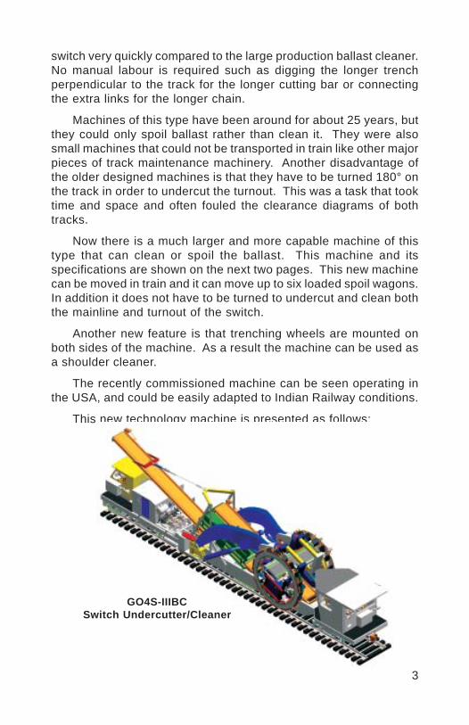
3
switch very quickly compared to the large production ballast cleaner.No manual labour is required such as digging the longer trenchperpendicular to the track for the longer cutting bar or connectingthe extra links for the longer chain.
Machines of this type have been around for about 25 years, butthey could only spoil ballast rather than clean it. They were alsosmall machines that could not be transported in train like other majorpieces of track maintenance machinery. Another disadvantage ofthe older designed machines is that they have to be turned 180° onthe track in order to undercut the turnout. This was a task that tooktime and space and often fouled the clearance diagrams of bothtracks.
Now there is a much larger and more capable machine of thistype that can clean or spoil the ballast. This machine and itsspecifications are shown on the next two pages. This new machinecan be moved in train and it can move up to six loaded spoil wagons.In addition it does not have to be turned to undercut and clean boththe mainline and turnout of the switch.
Another new feature is that trenching wheels are mounted onboth sides of the machine. As a result the machine can be used asa shoulder cleaner.
The recently commissioned machine can be seen operating inthe USA, and could be easily adapted to Indian Railway conditions.
This new technology machine is presented as follows:
GO4S-IIIBCSwitch Undercutter/Cleaner
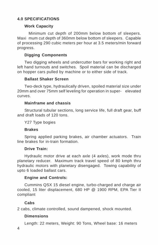
4
4.0 SPECIFICATIONS
Work Capacity
Minimum cut depth of 200mm below bottom of sleepers.Maxi mum cut depth of 360mm below bottom of sleepers. Capableof processing 290 cubic meters per hour at 3.5 meters/min forwardprogress.
Digging Components
Two digging wheels and undercutter bars for working right andleft hand turnouts and switches. Spoil material can be dischargedon hopper cars pulled by machine or to either side of track.
Ballast Shaker Screen
Two-deck type, hydraulically driven, spoiled material size under20mm and over 75mm self leveling for operation in super- elevatedcurves.
Mainframe and chassis
Structural tubular sections, long service life, full draft gear, buffand draft loads of 120 tons.
Y27 Type bogies
Brakes
Spring applied parking brakes, air chamber actuators. Trainline brakes for in-train formation.
Drive Train:
Hydraulic motor drive at each axle (4 axles), work mode thruplanetary reducer. Maximum track travel speed of 80 kmph thruhydraulic motors with planetary disengaged. Towing capability ofupto 6 loaded ballast cars.
Engine and Controls:
Cummins QSX 15 diesel engine, turbo-charged and charge aircooled, 15 liter displacement, 680 HP @ 1900 RPM, EPA Tier IIcompliant
Cabs2 cabs, climate controlled, sound dampened, shock mounted.
Dimensions
Length: 22 meters, Weight: 90 Tons, Wheel base: 16 meters

5
5.0 Grinding:
As explained in section III ballast cleaning of switches with highproduction machines is difficult. In a similar situation, with highproduction rail grinders, it is not possible to grind switches. Railgrinding programs to increase rail life are common with most majorrailways world wide, but grinding switches is not as common.Machines specifically designed for grinding switches have beenavailable for about 17 years.
A modern switch and crossing grinder is shown in the picture onthe next page. This machine has 20 grinding stones, and cancompletely grind switches at 0° - 75° to the gauge side and 0° - 45°on the field side. This includes grinding the frog and the gauge sideof the running rail at guard rails.
The picture below shows the most important safety reason togrind rail and switches. The picture at left shows the wheel to railcontact point close to the gauge face. This is a dangerouscondition since it can cause gauge corner cracking and eventuallycatastrophic rail failure. With proper profile grinding the correctwheel to rail contact pattern is shown after grinding in the pictureto the right.
Wheel to Rail Interface onGauge Corner
Wheel to Rail Interface awayfrom Gauge Corner (ProperContact)
Another reason for grinding switches is to remove surface defectsthat could also cause catastrophic rail failure. An example of surfacedefect before and after grinding is shown:
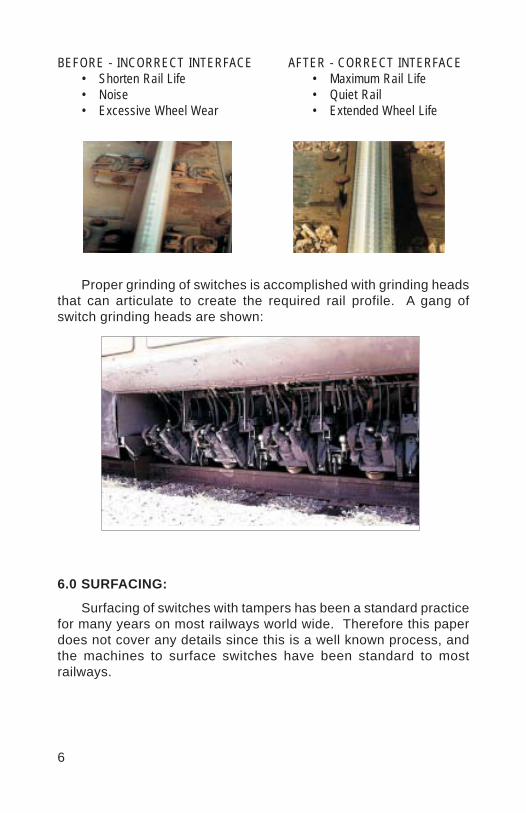
6
BEFORE - INCORRECT INTERFACE• Shorten Rail Life• Noise• Excessive Wheel Wear
AFTER - CORRECT INTERFACE• Maximum Rail Life• Quiet Rail• Extended Wheel Life
Proper grinding of switches is accomplished with grinding headsthat can articulate to create the required rail profile. A gang ofswitch grinding heads are shown:
6.0 SURFACING:
Surfacing of switches with tampers has been a standard practicefor many years on most railways world wide. Therefore this paperdoes not cover any details since this is a well known process, andthe machines to surface switches have been standard to mostrailways.
7
7.0 SUMMARY:
With the latest technology switch ballast cleaning and switchgrinding have become feasible with methods that require little timeon the track.
It is expected that these latest technologies will do for switchballast cleaning and switch grinding what the switch tamper did forsurfacing switches. In other words, it is expected that switch ballastcleaning and switch grinding will become common place for majorworld railways. The result is safer, quieter, and smoother ridingrailways.
8.0 CONCLUSION:
New machines are now available to efficiently grind switchesand also to clear ballast in switches. The switch grinders arespecifically designed to maintain the correct wheel to rail contactinterface for all running surfaces of the switch including the stockrail, points, and frog. Regarding ballast cleaning in switches, amachine designed specifically to clean ballast in switches is notbeing developed. When considering the cost to replace switches,including the time required for track occupancy, these new machinesworking in a properly planned program, have a fast payback in termsof safety and elimination of switch replacement cost.
Vinod
Placed Image
1
NEW TECHNOLOGIES TO SURVEY AND UPGRADEHIGH CAPACITY LINES
ING. RAINER WENTY *
SYNOPSIS
The term “High Capacity Line” cannot be unambiguously beassigned to a certain mode of traffic. It covers a wide range fromheavy haul freight traffic over densely used lines with mixed traffic tolines especially designated to high speed traffic. The term “High SpeedTraffic” again does not define an exact speed range, it depends onlocal conditions how this term Is defined. But whenever the speed orcapacity of a line is increased, the application of appropriate trackmaintenance and upgrading procedures is very important to enableoptimal and efficient use of the lines.
The continuous development and improvement of trackmaintenance machines has led to a series of designs for allapplications, that not only fulfil the high accuracy demands of highspeed railroads but also provide cost effective solutions. Either byincreasing the working speed or by implementing technologies thatsave precious raw materials Investment In high-tech machines withhigh-tech units is worthwhile. The output of the machines for tracklaying and maintenance is far greater than before and intelligent controlcircuits are being used increasingly. This has decisive effects on thework result and on the cost-effective performance of the jobs. Thefocus is always on the long-term effect of a maintenance operationand at the same time optimisation of the costs. Cheap methods,which do not fulfil these demands, cause resulting costs not only forthe operating department but also for the maintenance departmentwhich far exceed the original savings.
1.0 INTRODUCTION
The term “High Capacity Line” cannot be unambiguously beassigned to a certain mode of traffic. It covers a wide range fromheavy haul freight traffic over densely used lines with mixed traffic tolines especially designated to high speed traffic. The term “High SpeedTraffic” again does not define an exact speed range, it depends on
* General Manager Marketing and Technical Sales, Plasser & Theurer, Austria, Vienna

2
local conditions how this term is defined. But whenever the speed orcapacity of a line is increased, the application of appropriate trackmaintenance and upgrading procedures is very important to enableoptimal and efficient use of the lines.
The track maintenance technologies are developed continuouslyin order to meet the demands of high performance railway traffic.Investment in high-tech machines with high-tech units is worthwhile.The output of the machines for track laying and maintenance is fargreater than before and intelligent control circuits are being usedincreasingly. This has decisive effects on the work result and on thecost-effective performance of the jobs. The focus is always on thelong-term effect of a maintenance operation and at the same timeoptimisation of the costs. Cheap methods, which do not fulfill thesedemands, cause resulting costs not only for the operating departmentbut also for the maintenance department which far exceed the originalsavings.
2.0 HIGH SPEED TRAFFIC
2.1 Characteristics of High Speed Lines
High speed traffic is set up for the rapid connection ofconurbations. It is characterised on the one hand by the maximumspeed, but more important is, to achieve an unchanged high speedover a maximum of the route. On upgraded lines this is often realizableonly with the use of tilting train technology.
Generally high speed traffic is divided into three categories:
Speed up to 200 kmph.Speed from >200 to 300 kmph.Very high speed over 300 kmph.
During a 24 hour day, high speed lines very often have only certainperiods with very dense passenger traffic so that windows for additionalfreight traffic are available.
The permanent way for such routes must have a precise geometry,very narrow tolerances must be kept in the millimetre range. Routesfor tilting trains in addition require an exact compliance of the geometryof the transition curves to avoid maladjustment of the coach bodyinclination. In spite of the high demands on the track it must beconstructed and maintained in a low-cost way to safeguard the
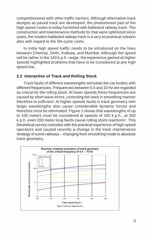
3
competitiveness with other traffic carriers. Although alternative trackdesigns as paved track are developed, the predominant part of thehigh speed routes is today furnished with ballasted railway track. Theconstruction and maintenance methods for that were optimized sinceyears, the modern ballasted railway track is a very economical solutionalso with regard to the life-cycle costs.
In India high speed traffic needs to be introduced on the linesbetween Chennai, Delhi, Kolkata, and Mumbai. Although the speedwill be rather in the 160 k.p.h. range, the experience gained at higherspeeds highlighted problems that have to be considered at any highspeed line.
2.2 Interaction of Track and Rolling Stock
Track faults of different wavelengths stimulate the car bodies withdifferent frequencies. Frequencies between 0.5 and 10 Hz are regardedas critical for the rolling stock. At lower speeds these frequencies arecaused by short wave errors, correcting the track in smoothing mannertherefore is sufficient. At higher speeds faults in track geometry withlarger wavelengths also cause considerable dynamic forces andtherefore must be eliminated. Figure 1 shows that wavelengths of upto 100 meters must be considered at speeds of 160 k.p.h., at 350k.p.h. even 200 meter long faults cause rolling stock reactions1. Thistheoretical survey coincides with the practical experience of high-speedoperators and caused recently a change in the track maintenancestrategy of some railways – changing from smoothing mode to absolutetrack geometry.

4
2.3 Absolute Track Geometry
On high speed lines deviations of track geometry from targetposition have to be kept to a minimum. High speed railways thereforeuse absolute reference systems for track geometry.
2.3.1 Austria, Germany
With the introduction of combined levelling- lining- tampingmachines in 1960, the general trend was to do smoothing trackcorrection only. It appeared very soon, that the tracks moved awayfrom the original position, and transition points were shifted. Thisresulted in loss of ride comfort and in increased rail stresses. From1972 onwards, in Austria and Germany therefore fixed reference pointswere established on monuments or catenary masts. The position ofthe track is defined in relation to the fixed points and the versines inbetween (figure 2,3), the target values are saved in the general trackdatabase.
2.3.2 France
The usual track correction method on high speed lines in Franceis to use a relative measuring base considering wavelengths of up to
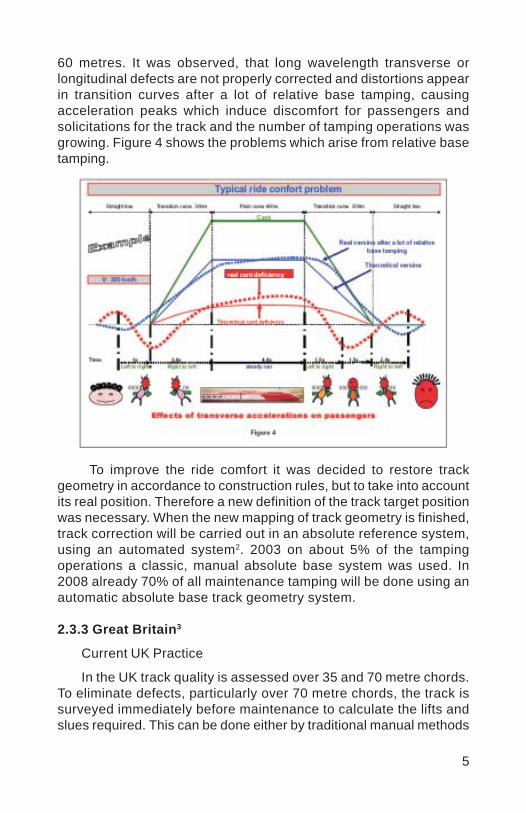
5
60 metres. It was observed, that long wavelength transverse orlongitudinal defects are not properly corrected and distortions appearin transition curves after a lot of relative base tamping, causingacceleration peaks which induce discomfort for passengers andsolicitations for the track and the number of tamping operations wasgrowing. Figure 4 shows the problems which arise from relative basetamping.
To improve the ride comfort it was decided to restore trackgeometry in accordance to construction rules, but to take into accountits real position. Therefore a new definition of the track target positionwas necessary. When the new mapping of track geometry is finished,track correction will be carried out in an absolute reference system,using an automated system2. 2003 on about 5% of the tampingoperations a classic, manual absolute base system was used. In2008 already 70% of all maintenance tamping will be done using anautomatic absolute base track geometry system.
2.3.3 Great Britain3
Current UK Practice
In the UK track quality is assessed over 35 and 70 metre chords.To eliminate defects, particularly over 70 metre chords, the track issurveyed immediately before maintenance to calculate the lifts andslues required. This can be done either by traditional manual methods
6
(measuring levels and versines with surveying equipment) or by thetamping machine with its track measuring trolleys and on-boardcomputer. A ‘smoothing’ or new design is calculated to eliminate theirregular top and line, ensuring that any tight structure, six-foot orOLE clearances are taken into account, and the maintenance tampand line is executed. Track geometry today, therefore, is maintainedto a quality measure and not always by continual reference to theoriginal design. Furthermore, as other railways have discovered, incalculating the lifts and slues to produce high quality, it is inevitablethat there will have to be a compromise to the datum plate offsetdimension if a complete re-survey has not been carried out.
Upgrading the West Coast Main Line
The line from London to Glasgow is the most heavily used mixedtraffic route in Britain. In 1997 a commercial contract was struckbetween Railtrack, the owner of the infrastructure, and Virgin Trainsthe new Franchisee for passenger trains on the route, to upgrade theline to 140mph and introduce ‘Pendolino’ tilting trains.
The track design policy for the upgrading project includes therequirement to register the ‘as built’ design on datum plates, fixedpredominately to OLE masts at intervals of 40 – 50 metres. Maintainingtrack geometry on a railway running 125mph tilting trains requires theurgent attention to minor discrete faults, particularly on high cantdeficiency curves, to prevent growth of the geometry defect and retainpassenger comfort. Therefore some form of Track Machine Guidanceseemed a logical requirement to be included in the emerging trackmaintenance policy in the spring of 2002.
Decision Point - EM-SAT
In March and April 2002 visits were made to Austria and Switzerlandto look at the two systems and in May, following a review with interestedparties from the UK rail industry, the West Coast project teamcommenced the development of a pilot using the Austrian systemdeveloped by Plasser and Theurer. Two EM-SAT machines (figure 5)were purchased. This system was chosen as it is compatible toPlasser and Theurer’s ALC tamping machine guidance software fittedto the majority of the UK track maintenance contractor’s tampingmachine fleet.

7
The Benefits:
There are many significant benefits to be gained. For the WCMLit is considered that these are:
The provision of configuration control of track design
The improvement in productivity of tamping machines as theneed to do a geometry measuring run is eliminated
Track geometry can be maintained to within +/-10mm ofdesign, consistently
The provision of baseline track design data to maintenanceengineers enabling them more accurately to monitor trackgeometry and plan maintenance
The provision of a survey base leading to the automation oftrack design
A reduction in the number of unrelated track improvementschemes
A reduction in the number of physical track surveys forrenewals
A reduction in the number of staff having to work on theinfrastructure
The opportunity to have software compatibility between EM-SAT survey data, existing on-track machine guidance softwareand track design software.
The mitigation of rolling contact fatigue on the rail head bythe control of long wave alignment.
8
2.3.4 Norway4
In 1999 the first tilting trains took up regular service in parts ofNorway’s railway network. Soon afterwards there was an incident:the wheel set axle of the powered front bogie of a tilt-bodied trainbroke.
Measuring runs were made on the line between Oslo andTrontheim. The test programme identified greater stresses generatedby certain categories of track geometry flaws at critical cross-sectionsof the measured wheel set axle in stretches of line with space-constrained layouts. These narrow layouts were characterised by smallradii with or without trackside points of constraint. Geometry flawswere mainly curvature changes in full curves. This resulted in the axlebeing subject to massive transverse displacement. Full curves withpoints of constraint and additional track geometry defects in level andalignment created enhanced stresses and strains. The measuredresults revealed that there was a close correlation between higherstresses at critical axle cross-sections and track geometry defects(i.e. changed curvature in tight curves). A similarly strong correlationwas observed for additional geometry flaws in level and alignment incombination with points of constraint.
It appears to be necessary that track maintenance operationsachieve a standard compliant quality of track position so that trackgeometry as a whole (rather than track position) is able to sustain therequired speeds.
2.4 Substructure
The ballast and the substructure form the basis for a stable trackand long lasting track geometry. Especially long wave errors can onlybe eliminated and avoided, if ballast bed and substructure havesufficient strength. Increase in line capacity very often demands ballastand subgrade rehabilitation, as the lines were not designed for higherloads and speeds.
3.0 TRACK MAINTENANCE
On high capacity tracks, the necessary maintenance must beensured, as for any other production plant. Production breaks formaintenance of catenary, signaling installations, rails and fasteningsand the track geometry should be scheduled so that the customerdoes not change to other traffic carriers due to unexpected production
9
breakdowns or delays. In these production breaks, it is of courseadvisable to bundle the various maintenance jobs to be performed.
New tracks must be serviced accordingly from the outset. Neglectof the maintenance in the initial phase of service life will cause inherentfailures that cannot be compensated later.
3.1 New Technologies
Track maintenance technologies are further developed continuallyin order to meet the requirements of high-capacity rail traffic. It isworthwhile investing in high-tech machines with sophisticated workunits. Machines for track maintenance have become more efficientand are increasingly equipped with intelligent controls. This hasdecisive effects on the work results and on the cost-efficientperformance of the tasks. The long-term effect of a maintenancemeasure together with optimisation of the costs stands at the forefront.
Some of the latest developments and trends are:
3.1.1 Track survey
Before any efficient and precise track maintenance work can becarried out, a track survey of the actual geometry measuring the leveland the alignment of the track has to be done. In the past extensivemanual track survey with sighting instruments was involved for thisjob.
If the track should be restored to design geometry or new designthe data of the database must be made available in the track. In curves.
The EM-SAT (figure 5) track survey car enables fully mechanisedmeasurement of the actual track geometry using a laser referencechord. It consists of a main machine with the computer system andthe laser receiver and an auxiliary trolley (“satellite”) which carriesthe laser transmitter. Measurements are taken in a cyclic sequence:the machine moves forward along the laser beam and deviations fromthe target geometry are measured and recorded. Every 50 to 150metres it has to stop at a fixed point and then the laser satellitetrolley is moved forward again. The working speed of the machine is8 km/h. While the average measuring speed (including all stops) is2.5 km/hr and besides the displacement and lifting values,superelevation and gauge faults can also be measured.
10
The recorded data and the calculated correction values aredisplayed on the computer screen in a similar manner as on the ALCscreen of the Tamping machine computer and can be reprocessedon-board or off-board if necessary. Electronic transmission of data toa tamping machine equipped with the ALC automatic guiding computerguarantees highest precision and at the same time prevents anytransmission faults which can occur in manual measuring.
The experience of DB-AG (German Railway) is: accuracy of1 mm, measuring speed of 1.5 to 2.6 km/hr and cost reduction ofEURO 3.- per metre of measured track.
The EM-SAT is not only used for track geometry survey whenpreparing for tamping of the track, it is also used on track relayingand rehabilitation sites and for the acceptance of newly built tracks. Itcan also be used to establish a track geometry database where thesedata are unknown.
3.1.1.1 Satellite-supported track surveying
Maintaining the fixed points is labour intensive and therefore quitecostly. Furthermore, when checking their position it is often foundthat their position has changed in the range of some centimetres. Themanual measurement of the track position in relation to the referencepoints slows down the measuring speed and is also a source ofinaccuracy and further costs.
For building new lines and for the survey of existing lines withregard to their general layout, the application of the satellite-supportedGlobal Positioning System is already standard technology. The latestdevelopment now is to use it also for the control of track geometry inconjunction with track maintenance.
11
From 1993 to 1995, the Geodetic Institute of the TechnicalUniversity Graz and the Research and Testing Department of Plasser& Theurer studied in a joint research project the possible uses ofGPS for track surveying. The objective was to answer the questionwhether GPS could achieve a similar accuracy to laser reference chordmeasuring methods.
The answer to this question was definitely negative. The highestabsolute alignment accuracy achievable with differential GPS isapproximately ± 6 mm. The accuracy in level is worse by a factorbetween 1.5 and 2. GPS is not precise enough to be used instead ofa laser reference chord measuring system. The requirements in termsof track correction values to guide tamping machines are about1 mm.
On the other hand the absolute accuracy of EM-SATmeasurements using a laser chord is better than 1 mm. To determinethe chord position and hence the actual and target track geometry ina co-ordinate system, fixed points are necessary which have thedrawbacks mentioned above.
GPS provides an elegant method of replacing fixed points. Theachievable accuracy in line of ± 6 mm and ± 9 to 12 mm in level isfully sufficient for these purposes.
The calibration of a fixed point (spacing and height) using spanmeasuring methods induces costs of € 130 (plus track safety costs)per measurement. This clearly demonstrates the savings potential ofthe combined use of EM-SAT and GPS (figure 6).
3.1.1.2 Combination of EM-SAT and GPS
The geographic information system (program) used for the mappingof the tracks is Geo++®-GNBAHN, which is a system for kinematicaltrack measuring5. It allows the complete recording of the trackgeometry, i.e. the three-dimensional track coordinates, thesuperelevation as well as the track gauge with high accuracy andhigh spatial density in one operation in real-time. GNBAHN wasdeveloped in co-operation with DB Netz AG and has already beenused successfully on many tracks of the DB Netz AG (figure 7).
12
The EM-SAT main machine is equipped with a GPS measuringdevice: a GPS antenna is mounted on the roof of the machine. Theantenna’s exact geometric position relative to the wheel points touchingthe rail is calibrated and recorded. Additionally, a GPS receiver of thelatest generation (simultaneous reception of Navstar and Glonasssatellites), which is linked to a computer for data recording, is mounted.The GNBAHN program for kinematical track measuring is installed onthe computer. A non-contact gauge measuring and superelevationmeasuring device provides the antenna’s relative position to the rail atall times. Additionally the main vehicle is fitted with the non-contactdistance measuring unit, which accurately measures the distancebetween the satellite trolley and the main vehicle, once the latter ishalted. This enables the relation between the curvature of the track,the laser reference chord data and the GPS co-ordinates to beestablished. On at least one calibrated reference point (at a distanceof 4 km for example), a GPS reference receiver is located and equippedwith a notebook for data recording. Both systems (reference receiverand rover) are linked to each other via radio.
While the satellite trolley is moving forward, the GPS receiverdata are received and stored on the notebook. The system operateson-line in real time, but off-line processing of the measured data isrecommended, as the EM-SAT continues to work with undiminishedquality even if the radio connection is interrupted. Not until the end ofa measuring period are all the collected data put together to calculatethe absolute track geometry co-ordinates and track correction values.

13
3.1.1.3 Use of the combined EM-SAT - GPS system
Simultaneous measuring of the actual track with laser referencechords and GPS makes it possible to store the laser reference chord(working in a local co-ordinate system) in the absolute WGS84 system(World Geodetic System 1984) , and thus to transform the highaccuracy relative laser reference chord data into absolute coordinates(WGS84).
Once the target position of the track is defined by its WGS84co-ordinates, the combined system is able to measure the deviationof the track from the target values at any time. Any point on the track,where GPS data is obtained, may be used as a fixed point. Therewould no longer be a need for defined fixed points - these could befreely chosen (figure 8)
On unmarked track, track coordinates with a very high internalaccuracy and an accuracy in the order of 1 cm at the chord endpoints are obtained. These provide an excellent basis for the layout ofa line or for line improvements by the surveying engineer. Using thecombined EM-SATGPS system has enormous saving potentialcompared to geodetic measuring methods.
EM-SATs equipped with a GPS measuring device are currently inoperation on the Austrian Federal Railways and on the German Railway.
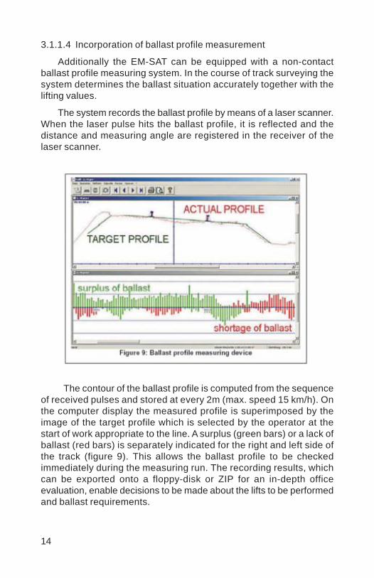
14
3.1.1.4 Incorporation of ballast profile measurement
Additionally the EM-SAT can be equipped with a non-contactballast profile measuring system. In the course of track surveying thesystem determines the ballast situation accurately together with thelifting values.
The system records the ballast profile by means of a laser scanner.When the laser pulse hits the ballast profile, it is reflected and thedistance and measuring angle are registered in the receiver of thelaser scanner.
The contour of the ballast profile is computed from the sequenceof received pulses and stored at every 2m (max. speed 15 km/h). Onthe computer display the measured profile is superimposed by theimage of the target profile which is selected by the operator at thestart of work appropriate to the line. A surplus (green bars) or a lack ofballast (red bars) is separately indicated for the right and left side ofthe track (figure 9). This allows the ballast profile to be checkedimmediately during the measuring run. The recording results, whichcan be exported onto a floppy-disk or ZIP for an in-depth officeevaluation, enable decisions to be made about the lifts to be performedand ballast requirements.
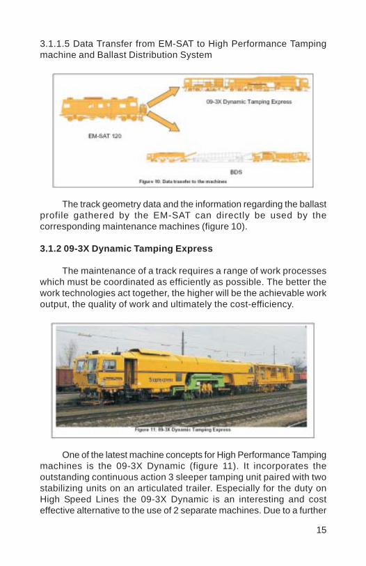
15
3.1.1.5 Data Transfer from EM-SAT to High Performance Tampingmachine and Ballast Distribution System
The track geometry data and the information regarding the ballastprofile gathered by the EM-SAT can directly be used by thecorresponding maintenance machines (figure 10).
3.1.2 09-3X Dynamic Tamping Express
The maintenance of a track requires a range of work processeswhich must be coordinated as efficiently as possible. The better thework technologies act together, the higher will be the achievable workoutput, the quality of work and ultimately the cost-efficiency.
One of the latest machine concepts for High Performance Tampingmachines is the 09-3X Dynamic (figure 11). It incorporates theoutstanding continuous action 3 sleeper tamping unit paired with twostabilizing units on an articulated trailer. Especially for the duty onHigh Speed Lines the 09-3X Dynamic is an interesting and costeffective alternative to the use of 2 separate machines. Due to a further
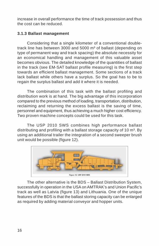
16
increase in overall performance the time of track possession and thusthe cost can be reduced.
3.1.3 Ballast management
Considering that a single kilometer of a conventional double-track line has between 3000 and 5000 m³ of ballast (depending ontype of permanent way and track spacing) the absolute necessity foran economical handling and management of this valuable assetbecomes obvious. The detailed knowledge of the quantities of ballastin the track (see EM-SAT ballast profile measuring) is the first steptowards an efficient ballast management. Some sections of a tracklack ballast while others have a surplus. So the goal has to be toregain the surplus ballast and add it where it is needed.
The combination of this task with the ballast profiling anddistribution work is at hand. The big advantage of this incorporationcompared to the previous method of loading, transportation, distribution,reclaiming and returning the excess ballast is the saving of time,personnel and equipment, thus achieving a much higher cost efficiency.Two proven machine concepts could be used for this task.
The USP 2010 SWS combines high performance ballastdistributing and profiling with a ballast storage capacity of 10 m³. Byusing an additional trailer the integration of a second sweeper brushunit would be possible (figure 12).
The other alternative is the BDS – Ballast Distribution System,successfully in operation in the USA on AMTRAK’s and Union Pacific’strack as well as Latvia (figure 13) and Lithuania. One of the uniquefeatures of the BDS is that the ballast storing capacity can be enlargedas required by adding material conveyor and hopper units.
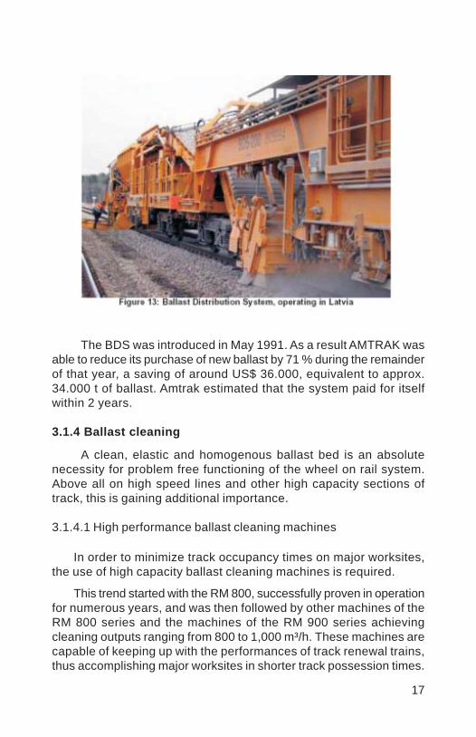
17
The BDS was introduced in May 1991. As a result AMTRAK wasable to reduce its purchase of new ballast by 71 % during the remainderof that year, a saving of around US$ 36.000, equivalent to approx.34.000 t of ballast. Amtrak estimated that the system paid for itselfwithin 2 years.
3.1.4 Ballast cleaning
A clean, elastic and homogenous ballast bed is an absolutenecessity for problem free functioning of the wheel on rail system.Above all on high speed lines and other high capacity sections oftrack, this is gaining additional importance.
3.1.4.1 High performance ballast cleaning machines
In order to minimize track occupancy times on major worksites,the use of high capacity ballast cleaning machines is required.
This trend started with the RM 800, successfully proven in operationfor numerous years, and was then followed by other machines of theRM 800 series and the machines of the RM 900 series achievingcleaning outputs ranging from 800 to 1,000 m³/h. These machines arecapable of keeping up with the performances of track renewal trains,thus accomplishing major worksites in shorter track possession times.
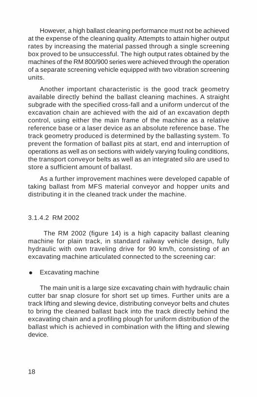
18
However, a high ballast cleaning performance must not be achievedat the expense of the cleaning quality. Attempts to attain higher outputrates by increasing the material passed through a single screeningbox proved to be unsuccessful. The high output rates obtained by themachines of the RM 800/900 series were achieved through the operationof a separate screening vehicle equipped with two vibration screeningunits.
Another important characteristic is the good track geometryavailable directly behind the ballast cleaning machines. A straightsubgrade with the specified cross-fall and a uniform undercut of theexcavation chain are achieved with the aid of an excavation depthcontrol, using either the main frame of the machine as a relativereference base or a laser device as an absolute reference base. Thetrack geometry produced is determined by the ballasting system. Toprevent the formation of ballast pits at start, end and interruption ofoperations as well as on sections with widely varying fouling conditions,the transport conveyor belts as well as an integrated silo are used tostore a sufficient amount of ballast.
As a further improvement machines were developed capable oftaking ballast from MFS material conveyor and hopper units anddistributing it in the cleaned track under the machine.
3.1.4.2 RM 2002
The RM 2002 (figure 14) is a high capacity ballast cleaningmachine for plain track, in standard railway vehicle design, fullyhydraulic with own traveling drive for 90 km/h, consisting of anexcavating machine articulated connected to the screening car:
Excavating machine
The main unit is a large size excavating chain with hydraulic chaincutter bar snap closure for short set up times. Further units are atrack lifting and slewing device, distributing conveyor belts and chutesto bring the cleaned ballast back into the track directly behind theexcavating chain and a profiling plough for uniform distribution of theballast which is achieved in combination with the lifting and slewingdevice.
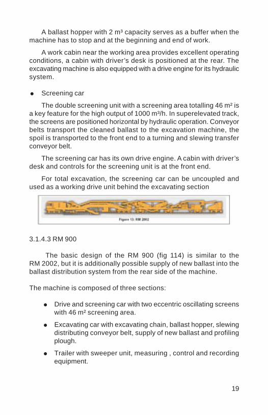
19
A ballast hopper with 2 m³ capacity serves as a buffer when themachine has to stop and at the beginning and end of work.
A work cabin near the working area provides excellent operatingconditions, a cabin with driver’s desk is positioned at the rear. Theexcavating machine is also equipped with a drive engine for its hydraulicsystem.
Screening car
The double screening unit with a screening area totalling 46 m² isa key feature for the high output of 1000 m³/h. In superelevated track,the screens are positioned horizontal by hydraulic operation. Conveyorbelts transport the cleaned ballast to the excavation machine, thespoil is transported to the front end to a turning and slewing transferconveyor belt.
The screening car has its own drive engine. A cabin with driver’sdesk and controls for the screening unit is at the front end.
For total excavation, the screening car can be uncoupled andused as a working drive unit behind the excavating section
3.1.4.3 RM 900
The basic design of the RM 900 (fig 114) is similar to theRM 2002, but it is additionally possible supply of new ballast into theballast distribution system from the rear side of the machine.
The machine is composed of three sections:
Drive and screening car with two eccentric oscillating screenswith 46 m² screening area.
Excavating car with excavating chain, ballast hopper, slewingdistributing conveyor belt, supply of new ballast and profilingplough.
Trailer with sweeper unit, measuring , control and recordingequipment.
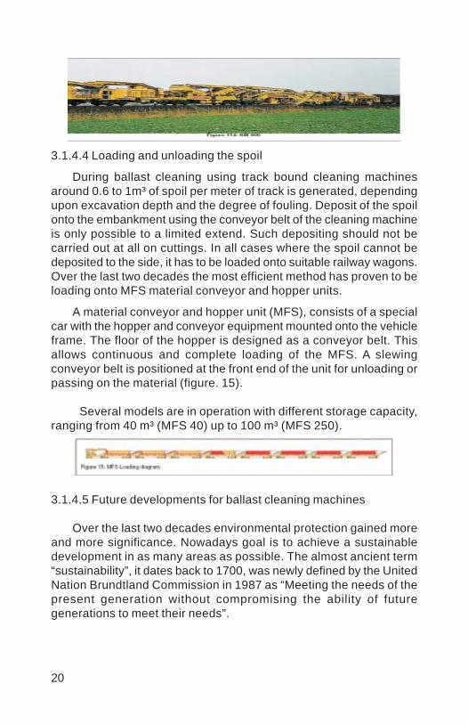
20
3.1.4.4 Loading and unloading the spoil
During ballast cleaning using track bound cleaning machinesaround 0.6 to 1m³ of spoil per meter of track is generated, dependingupon excavation depth and the degree of fouling. Deposit of the spoilonto the embankment using the conveyor belt of the cleaning machineis only possible to a limited extend. Such depositing should not becarried out at all on cuttings. In all cases where the spoil cannot bedeposited to the side, it has to be loaded onto suitable railway wagons.Over the last two decades the most efficient method has proven to beloading onto MFS material conveyor and hopper units.
A material conveyor and hopper unit (MFS), consists of a specialcar with the hopper and conveyor equipment mounted onto the vehicleframe. The floor of the hopper is designed as a conveyor belt. Thisallows continuous and complete loading of the MFS. A slewingconveyor belt is positioned at the front end of the unit for unloading orpassing on the material (figure. 15).
Several models are in operation with different storage capacity,ranging from 40 m³ (MFS 40) up to 100 m³ (MFS 250).
3.1.4.5 Future developments for ballast cleaning machines
Over the last two decades environmental protection gained moreand more significance. Nowadays goal is to achieve a sustainabledevelopment in as many areas as possible. The almost ancient term“sustainability”, it dates back to 1700, was newly defined by the UnitedNation Brundtland Commission in 1987 as “Meeting the needs of thepresent generation without compromising the ability of futuregenerations to meet their needs”.
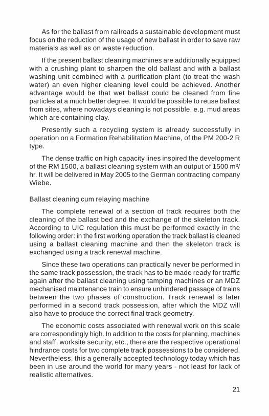
21
As for the ballast from railroads a sustainable development mustfocus on the reduction of the usage of new ballast in order to save rawmaterials as well as on waste reduction.
If the present ballast cleaning machines are additionally equippedwith a crushing plant to sharpen the old ballast and with a ballastwashing unit combined with a purification plant (to treat the washwater) an even higher cleaning level could be achieved. Anotheradvantage would be that wet ballast could be cleaned from fineparticles at a much better degree. It would be possible to reuse ballastfrom sites, where nowadays cleaning is not possible, e.g. mud areaswhich are containing clay.
Presently such a recycling system is already successfully inoperation on a Formation Rehabilitation Machine, of the PM 200-2 Rtype.
The dense traffic on high capacity lines inspired the developmentof the RM 1500, a ballast cleaning system with an output of 1500 m³/hr. It will be delivered in May 2005 to the German contracting companyWiebe.
Ballast cleaning cum relaying machine
The complete renewal of a section of track requires both thecleaning of the ballast bed and the exchange of the skeleton track.According to UIC regulation this must be performed exactly in thefollowing order: in the first working operation the track ballast is cleanedusing a ballast cleaning machine and then the skeleton track isexchanged using a track renewal machine.
Since these two operations can practically never be performed inthe same track possession, the track has to be made ready for trafficagain after the ballast cleaning using tamping machines or an MDZmechanised maintenance train to ensure unhindered passage of trainsbetween the two phases of construction. Track renewal is laterperformed in a second track possession, after which the MDZ willalso have to produce the correct final track geometry.
The economic costs associated with renewal work on this scaleare correspondingly high. In addition to the costs for planning, machinesand staff, worksite security, etc., there are the respective operationalhindrance costs for two complete track possessions to be considered.Nevertheless, this a generally accepted technology today which hasbeen in use around the world for many years - not least for lack ofrealistic alternatives.

22
The combination of ballast cleaning and track renewal in onemachine has already been discussed for some time. Above all, therailway administrations want such a technology because the associatedsaving potentials would be enormous.
RU 800 S A machine revolutionises line renewal
Now the answer is here: Plasser & Theurer is designing the RU800 S, a continuous action ballast bed cleaning and track renewaltrain. This machine combines the two working operations of ballastbed cleaning and track renewal in one single machine. This makes itpossible to perform the renewal of sections of track in only one trackpossession, with all the associated technological, logistic and aboveall economic advantages. It will be supplied to the Austrian ContractorSwietelsky in May 2005 (figure 16).
3.1.5 Formation rehabilitation
Not only the rise in axle loads and train speeds, but also theconstruction of tracks on formations with low bearing capacity andneglected drainage will lead to formation failure6. Göbel-Lieberenz-Richter from Dresden, Germany7, see defects in the bearing capacityof the formation as the prototype of formation failures by which mudpockets are created which further on by the presence of water lead topumping of slurry. The whole track becomes vulnerable to frost andlooses its horizontal and vertical stability. Defects in the bearingcapacity are caused by an increase in loads and speeds on existinglines, but also by deferred ballast cleaning and blocked drainage. Itcan be prevented by placing a blanket material between the ballastand the formation. A typical attrition and mud pumping spot is shownin figure 17.
The first indication of formation failure is the necessity of frequenttrack tamping and very quick return of ballast fouling after trackundercutting and ballast cleaning. Track geometry recording cars withthe ADA 2 analysing system made by Plasser & Theurer can deliverquality indices for the formation. The formation index is calculated onan empiric basis and uses the twist based on l6 meters.
Today different methods are applied for formation rehabilitationand protection, but it has been found that the application of a correctly
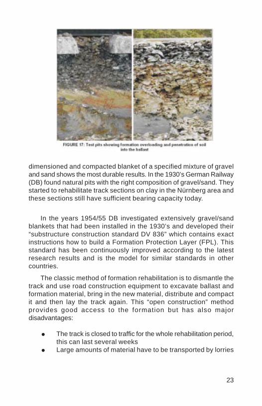
23
dimensioned and compacted blanket of a specified mixture of graveland sand shows the most durable results. In the 1930’s German Railway(DB) found natural pits with the right composition of gravel/sand. Theystarted to rehabilitate track sections on clay in the Nürnberg area andthese sections still have sufficient bearing capacity today.
In the years 1954/55 DB investigated extensively gravel/sandblankets that had been installed in the 1930’s and developed their“substructure construction standard DV 836” which contains exactinstructions how to build a Formation Protection Layer (FPL). Thisstandard has been continuously improved according to the latestresearch results and is the model for similar standards in othercountries.
The classic method of formation rehabilitation is to dismantle thetrack and use road construction equipment to excavate ballast andformation material, bring in the new material, distribute and compactit and then lay the track again. This “open construction” methodprovides good access to the formation but has also majordisadvantages:
The track is closed to traffic for the whole rehabilitation period,this can last several weeksLarge amounts of material have to be transported by lorries
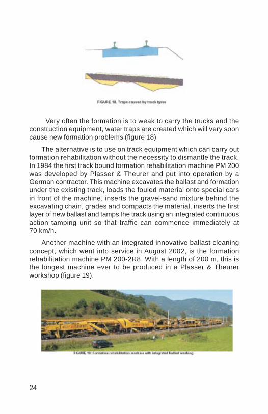
24
Very often the formation is to weak to carry the trucks and theconstruction equipment, water traps are created which will very sooncause new formation problems (figure 18)
The alternative is to use on track equipment which can carry outformation rehabilitation without the necessity to dismantle the track.In 1984 the first track bound formation rehabilitation machine PM 200was developed by Plasser & Theurer and put into operation by aGerman contractor. This machine excavates the ballast and formationunder the existing track, loads the fouled material onto special carsin front of the machine, inserts the gravel-sand mixture behind theexcavating chain, grades and compacts the material, inserts the firstlayer of new ballast and tamps the track using an integrated continuousaction tamping unit so that traffic can commence immediately at70 km/h.
Another machine with an integrated innovative ballast cleaningconcept, which went into service in August 2002, is the formationrehabilitation machine PM 200-2R8. With a length of 200 m, this isthe longest machine ever to be produced in a Plasser & Theurerworkshop (figure 19).
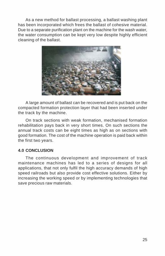
25
As a new method for ballast processing, a ballast washing planthas been incorporated which frees the ballast of cohesive material.Due to a separate purification plant on the machine for the wash water,the water consumption can be kept very low despite highly efficientcleaning of the ballast.
A large amount of ballast can be recovered and is put back on thecompacted formation protection layer that had been inserted underthe track by the machine.
On track sections with weak formation, mechanised formationrehabilitation pays back in very short times. On such sections theannual track costs can be eight times as high as on sections withgood formation. The cost of the machine operation is paid back withinthe first two years.
4.0 CONCLUSION
The continuous development and improvement of trackmaintenance machines has led to a series of designs for allapplications, that not only fulfil the high accuracy demands of highspeed railroads but also provide cost effective solutions. Either byincreasing the working speed or by implementing technologies thatsave precious raw materials.
26
LITERATURE:
1 Haigermoser, Dr. Dipl.Ing. Andreas: Demands of rolling stockon track quality, paper delivered to working committee trackof ÖVG on 2004-11-08
2 Le Bihan, André: Track geometry maintenance on high speedlines – SNCF’s experience, ÖVG Conference “Optimising theWheel/Rail System – Quality, Cost Efficiency, Financing”, 14.-16. September, Salzburg, Austria
3 Spoors, Richard: Introduction of fixed point based geometryon British tracks, ÖVG Conference “Optimising the Wheel/Rail System – Quality, Cost Efficiency, Financing”, 14.-16.September, Salzburg, Austria
4 Gåsemyr, Hallstein; Ly, Jon N; Müller, Roland: Recent findingsin vehicle-track interaction, ÖVG Conference “Optimising theWheel/Rail System – Quality, Cost Efficiency, Financing”,14.-16. September, Salzburg, Austria
5 Wübbena, Gerhard; Lahr, Bodo; Marx, Lothar; Lichtberger,Bernhard: GPS satelliteassisted track surveying on GermanRail, Rail Engineering International, 2003/4, p. 13…16
6. Selig, Ernest T;. Waters, John M.: Track Geotechnology andSubstructure Management.Thomas Telford Services Ltd,London, 1994. pp. 10.9-10.19
7 Göbel, Claus; Lieberenz, Klaus; Richter, Frank: DerEisenbahnunterbau (The Railway Formation). German Railway(DB)-Fachbuch No 8-20, Eisenbahn Fachverlag, Heidelberg-Mainz, 1996. pp. 164-173
8 Beilhack, Fred: Planumsverbesserungsmaschine der zweitenGeneration (Formation Rehabilitation Machine of the SecondGeneration) PM 200-2 R, ETR EisenbahntechnischeRundschau.–. No 4/2004, pp. 225-228
Vinod
Placed Image

1
ELECTRONICS MONITORING SYSTEM OFPATROLLING
ALOK TIWARI*
* Sr. DEN/Central/Bangalore, SW Railway
1.0 INTRODUCTION
In Indian Railways, Keyman patrolling of railway track is a vitalactivity, which ensures safety of travelling public and train servicesat large. With its vast network of railway tracks, spread over thecountry and with more than 63,000 route km of track, thecontinuous vigil of the railway track has its own importance.Keyman is of vital importance, because he is the nominated guardof the track all the times to ensure safety of the train operation.There are number of incidents, where alert keyman has avertedseveral untoward incidents and thus saved lot of lives. With thelatest technology developments, an attempt is made for introducingthe electronic surveillance system in track patrolling.
2.0 PRESENT SYSTEM
At present, the keyman of a particular gang walks over hisentire beat length (about 6 km on each line in double line and about12 km in single line) per day for checking the conditions of track toensure safe passage of trains. After completing his beat lengthinspection, he will carry out the programmed works as set in hisdiary. His presence will be checked during trolley inspection, Footplate/LV /IC inspections by higher officials.
SYNOPSIS
Patrolling of track by keyman & patrolman is a vital activity.However except patrol chart there is no foolproof methodavailable to check that the keyman/patrolman has actually done thepatrolling of the track in the section. With development of technologyin electronics it is possible to check this.
A new Electronic Monitoring System has been developed&introduced in Bangalore-Mysore section of Bangalore Division inSouth Western Railway. The paper describes the system in detail &its advantages and cost benefits.
2
3.0 DRAW BACKS IN EXISTING SYSTEM
The existing monitoring of track patrolling is not fool proofand is prone to errors and is very difficult to cross check. It is mainlydepending on the sincerity of the individual doing keyman patrolling.During inspections, the presence of keyman is noted, but the existingsystem does not ensure, whether, the keyman covered entire beat& if so, what time? Availability of keyman & patrolling of beat isnecessary in Indian Railway system, more particularly, when lawand order problems are increasing day by day. With increase of antisocial activities, it is utmost necessary to ensure that keyman doespatrolling regularly every day, round the year. There is no accurateand cost effective system available so far for better surveillance ofthe keyman patrolling system.
4.0 E–TRACKING:
To over come the above said draw backs, the system ofE- tracking is developed and introduced in Bangalore – Mysoresection of Bangalore division in South Western Railway.
After many round of discussion, M/S Techmech Engineers/Bangalore was engaged to develop Electronics MonitoringSystem. This was installed on experimental basis for a length ofone gang beat in Bangalore – Salem. The system was continuouslychecked for about one and half year and the performance was foundsatisfactory. This system was found to be useful for better monitoringthe keyman patrol and also night patrolling. After field trials, theE-tracking system is now implemented in Bangalore – Mysore sectionof South Western Railway.
The system consists of concealed passive tags fixed along sidethe track at specified locations and hand held proximity readerswith interface facilities with mobile printer and PC connectivity. Thereader is powered by a self contained rechargeable and theocation identifier, without any need for power source. The tag isweather proof and can be embedded under cement plaster toprevent pilferage.
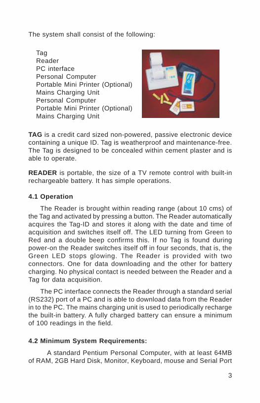
3
TagReaderPC interfacePersonal ComputerPortable Mini Printer (Optional)Mains Charging UnitPersonal ComputerPortable Mini Printer (Optional)Mains Charging Unit
TAG is a credit card sized non-powered, passive electronic devicecontaining a unique ID. Tag is weatherproof and maintenance-free.The Tag is designed to be concealed within cement plaster and isable to operate.
READER is portable, the size of a TV remote control with built-inrechargeable battery. It has simple operations.
4.1 Operation
The Reader is brought within reading range (about 10 cms) ofthe Tag and activated by pressing a button. The Reader automaticallyacquires the Tag-ID and stores it along with the date and time ofacquisition and switches itself off. The LED turning from Green toRed and a double beep confirms this. If no Tag is found duringpower-on the Reader switches itself off in four seconds, that is, theGreen LED stops glowing. The Reader is provided with twoconnectors. One for data downloading and the other for batterycharging. No physical contact is needed between the Reader and aTag for data acquisition.
The PC interface connects the Reader through a standard serial(RS232) port of a PC and is able to download data from the Readerin to the PC. The mains charging unit is used to periodically rechargethe built-in battery. A fully charged battery can ensure a minimumof 100 readings in the field.
4.2 Minimum System Requirements:
A standard Pentium Personal Computer, with at least 64MBof RAM, 2GB Hard Disk, Monitor, Keyboard, mouse and Serial Port
The system shall consist of the following:
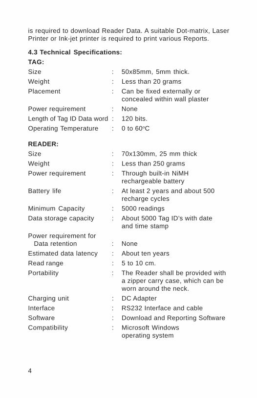
4
is required to download Reader Data. A suitable Dot-matrix, LaserPrinter or Ink-jet printer is required to print various Reports.
4.3 Technical Specifications:TAG:Size : 50x85mm, 5mm thick.Weight : Less than 20 gramsPlacement : Can be fixed externally or
concealed within wall plasterPower requirement : NoneLength of Tag ID Data word : 120 bits.Operating Temperature : 0 to 60oC
READER:Size : 70x130mm, 25 mm thickWeight : Less than 250 gramsPower requirement : Through built-in NiMH
rechargeable batteryBattery life : At least 2 years and about 500
recharge cyclesMinimum Capacity : 5000 readingsData storage capacity : About 5000 Tag ID’s with date
and time stampPower requirement for
Data retention : NoneEstimated data latency : About ten yearsRead range : 5 to 10 cm.Portability : The Reader shall be provided with
a zipper carry case, which can beworn around the neck.
Charging unit : DC AdapterInterface : RS232 Interface and cableSoftware : Download and Reporting SoftwareCompatibility : Microsoft Windows
operating system

5
INTERFACE UNIT:Size : 80x52mm & 30 mm thickWeight : Less than 50 gramsPower requirement : NoneCable ends : 9 pin D Shell and RJ11
CHARGING UNIT:Size : 80x48mm, 50 mm thickWeight : Less than 100 gramsInput Voltage : 230 V ACOutput Voltage : 12 V DCCurrent : 250 milli Amps
OPTIONAL ACCESSORIES:Portable PrinterTechnical Specifications for Portable printer.Size : PortableWeight : Less than 500 grmsPower requirement : Dual option to work on batteries
and AC MainsBattery Type : RechargeablePrinter Type : Dot matrixInterface compatibility : Interfaces with Reader through
RS232 to print Reader DataPaper Size : Standard 57mm width
plain paper rollsPrint speed : 15 CPSCapability : Prints Reader ID, Tag ID,
Individual IDDate and time of recordings
5.0 BRIEF MANUFACTURING AND TESTING PROCEDURESA single board is used for the reader and for the interface unit.
These boards are double-sided Plate through Hole boards. 80 % of theelectronic components are Surface Mount Devices and do not haveany lead wires. The populated PCBs are soldered. The microprocessoris loaded with embedded software. The PCB is assembled inside theenclosure. The real time clock is reset and calibrated.
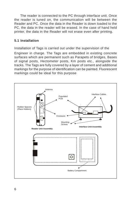
6
The reader is connected to the PC through interface unit. Oncethe reader is tuned on, the communication will be between theReader and PC. Once the data in the Reader is down loaded to thePC, the data in the reader will be erased. In the case of hand heldprinter, the data in the Reader will not erase even after printing.
5.1 Installation
Installation of Tags is carried out under the supervision of theEngineer in charge. The Tags are embedded in existing concretesurfaces which are permanent such as Parapets of bridges, Basesof signal posts, Hectometer posts, Km posts etc., alongside thetracks. The Tags are fully covered by a layer of cement and additionalmarkings for the purpose of identification can be painted. Fluorescentmarkings could be ideal for this purpose
Rubber Spacers(Place Holders)
PopulatedPCB
Enclosure
Reader Unit AssemblyInterface Unit Assembly
Interface Cables
MountingScrews
Antenna
Battery Compartment
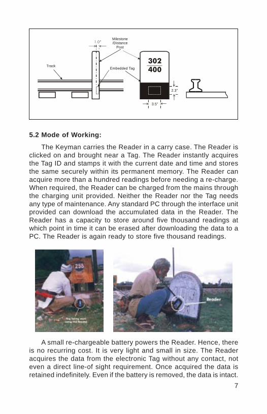
7
5.2 Mode of Working:
The Keyman carries the Reader in a carry case. The Reader isclicked on and brought near a Tag. The Reader instantly acquiresthe Tag ID and stamps it with the current date and time and storesthe same securely within its permanent memory. The Reader canacquire more than a hundred readings before needing a re-charge.When required, the Reader can be charged from the mains throughthe charging unit provided. Neither the Reader nor the Tag needsany type of maintenance. Any standard PC through the interface unitprovided can download the accumulated data in the Reader. TheReader has a capacity to store around five thousand readings atwhich point in time it can be erased after downloading the data to aPC. The Reader is again ready to store five thousand readings.
A small re-chargeable battery powers the Reader. Hence, thereis no recurring cost. It is very light and small in size. The Readeracquires the data from the electronic Tag without any contact, noteven a direct line-of sight requirement. Once acquired the data isretained indefinitely. Even if the battery is removed, the data is intact.
Track Embedded Tag
Milestone/Distance
Post1.0”
302400
3.5”
2.3”

8
The outer casing is made from a superior engineering plastic-ABS.Thus it needs no painting or any other maintenance.
The Reader has a capacity to store about 5000 readings. Thiscan be printed out in the field itself by using a small field printer.Any standard PC through the interface cable provided can generatemore comprehensive reports.
5.3 Reports
Data reporting software is provided with the system. Thissoftware enables the Administrator to generate reports either of theentire range of data stored in the computer database or selectivelybetween any two user specified dates. The stored data can also beexported to any other standard computer formats. Thus the reportingsoftware provides a very powerful tool for the management to check,control and manage the track patrolling and hence track integrityand passenger safety. A second provision allows for downloadingof data in raw format directly to a portable field printer without theneed for a computer. This offers an ideal solution for scrutiny bythe PWI during his inspections of the track and key-men.
5.4 Print outs
Extracts of live data from the field show the following:
Date of patrol – the actual date on which the key-manchecked the trackTime of patrol - the actual time of day when thekey-man checked the trackLocation ID - the actual location on the track whichthe key-man had traversedName of the person who did the Patrol for the givendate
The results are reliable and the field people cannot tamper them.The print outs can be taken for different options, such as locationwise, date wise, Reader ID wise, Personnel ID wise. Summaryreports, consolidated reports, list of locations and unvisited pointsetc can be obtained from the PC. The print out from the portableprinter will give date, time, reader ID and tag ID. It can be printed inascending order or descending order. It is very friendly without anycomplications. Print out of key man & security patrolling are shownin Annexure I & II.
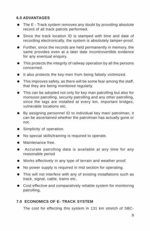
9
6.0 ADVANTAGES
The E - Track system removes any doubt by providing absoluterecord of all track patrols performed.
Since the track location ID is stamped with time and date ofrecording electronically, the system is absolutely tamper-proof.
Further, since the records are held permanently in memory, thesame provides even at a later date incontrovertible evidencefor any eventual enquiry.
This protects the integrity of railway operation by all the personsconcerned.
It also protects the key-men from being falsely victimized.
This improves safety, as there will be some fear among the staff,that they are being monitored regularly.
This can be adopted not only for key man patrolling but also formonsoon patrolling, security patrolling and any other patrolling,since the tags are installed at every km, important bridges,vulnerable locations etc,
By assigning personnel ID to individual key man/ patrolman, itcan be ascertained whether the patrolman has actually gone ornot.
Simplicity of operation.
No special skills/training is required to operate.
Maintenance free.
Accurate patrolling data is available at any time for anyreasonable period
Works effectively in any type of terrain and weather proof.
No power supply is required in mid section for operating.
This will not interfere with any of existing installations such astrack, signal, cable, trains etc,
Cost effective and comparatively reliable system for monitoringpatrolling,
7.0 ECONOMICS OF E- TRACK SYSTEM
The cost for effecting this system in 131 km stretch of SBC-
10
MYS section is only about Rs.2.44 lakhs or Rs. 1862 per km oftrack. When compared with the monitoring of safety related keyman patrolling, this amount is meagre. There is no recurringexpenditure involved, since the tags are fixed permanently. Theprocurement of software is also one time exercise. There is nomaintenance expenditure, except to keep the readers in workingcondition, which may be about Rs.500 per Reader. This works outto about Rs.12,000 per year for 24 Readers, which is very marginal.
8.0 CONCLUSION
This E tracking system has been implemented in full SBC- MYSsection of South Western Railway and the results are verysatisfactory. Among the systems available at present for bettermonitoring of track patrolling, E- tracking will definitely better others.
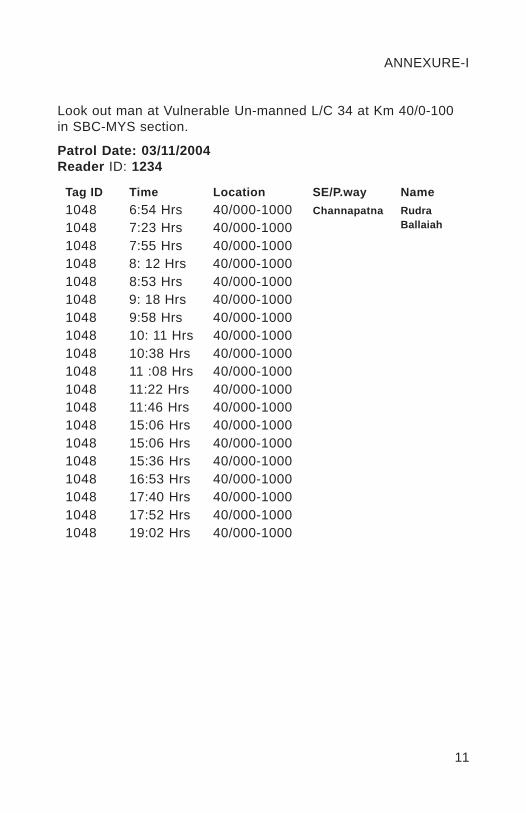
11
ANNEXURE-I
Look out man at Vulnerable Un-manned L/C 34 at Km 40/0-100in SBC-MYS section.
Patrol Date: 03/11/2004Reader ID: 1234
Tag ID Time Location SE/P.way Name1048 6:54 Hrs 40/000-1000 Channapatna Rudra1048 7:23 Hrs 40/000-1000 Ballaiah
1048 7:55 Hrs 40/000-10001048 8: 12 Hrs 40/000-10001048 8:53 Hrs 40/000-10001048 9: 18 Hrs 40/000-10001048 9:58 Hrs 40/000-10001048 10: 11 Hrs 40/000-10001048 10:38 Hrs 40/000-10001048 11 :08 Hrs 40/000-10001048 11:22 Hrs 40/000-10001048 11:46 Hrs 40/000-10001048 15:06 Hrs 40/000-10001048 15:06 Hrs 40/000-10001048 15:36 Hrs 40/000-10001048 16:53 Hrs 40/000-10001048 17:40 Hrs 40/000-10001048 17:52 Hrs 40/000-10001048 19:02 Hrs 40/000-1000
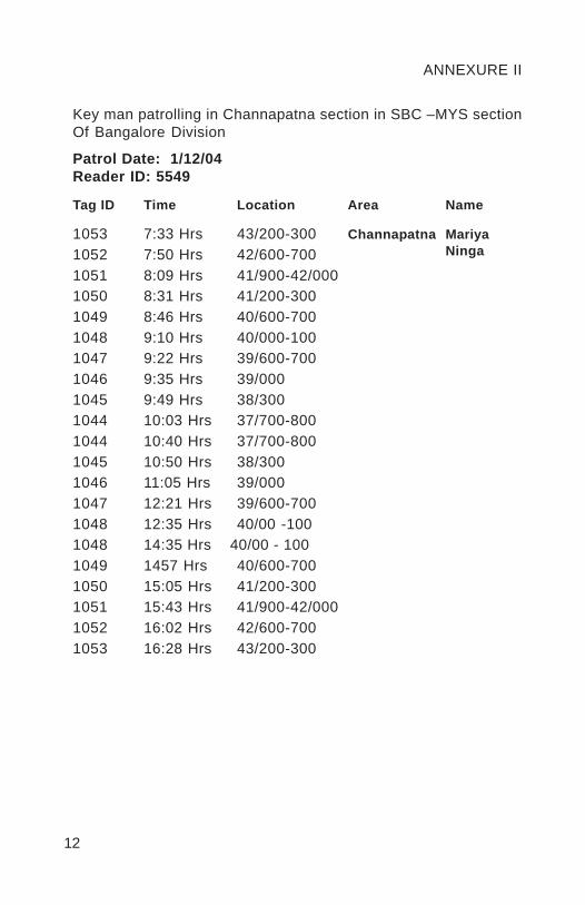
12
ANNEXURE II
Key man patrolling in Channapatna section in SBC –MYS sectionOf Bangalore Division
Patrol Date: 1/12/04Reader ID: 5549
Tag ID Time Location Area Name
1053 7:33 Hrs 43/200-300 Channapatna Mariya1052 7:50 Hrs 42/600-700 Ninga
1051 8:09 Hrs 41/900-42/0001050 8:31 Hrs 41/200-3001049 8:46 Hrs 40/600-7001048 9:10 Hrs 40/000-1001047 9:22 Hrs 39/600-7001046 9:35 Hrs 39/0001045 9:49 Hrs 38/3001044 10:03 Hrs 37/700-8001044 10:40 Hrs 37/700-8001045 10:50 Hrs 38/3001046 11:05 Hrs 39/0001047 12:21 Hrs 39/600-7001048 12:35 Hrs 40/00 -1001048 14:35 Hrs 40/00 - 1001049 1457 Hrs 40/600-7001050 15:05 Hrs 41/200-3001051 15:43 Hrs 41/900-42/0001052 16:02 Hrs 42/600-7001053 16:28 Hrs 43/200-300
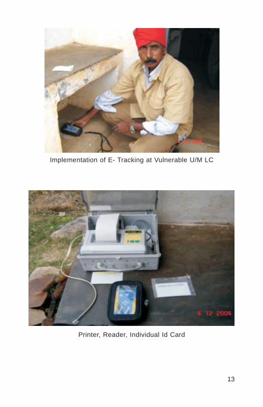
13
Implementation of E- Tracking at Vulnerable U/M LC
Printer, Reader, Individual Id Card

14
Embedding Tag in Km Post Embedding Tag in Pedestal
Embedding Tag Clicking of Reader Near Tag
Vinod
Placed Image
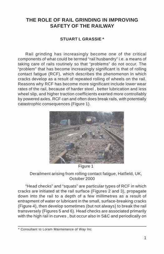
1
THE ROLE OF RAIL GRINDING IN IMPROVINGSAFETY OF THE RAILWAY
STUART L GRASSIE *
Rail grinding has increasingly become one of the criticalcomponents of what could be termed “rail husbandry” i.e. a means oftaking care of rails routinely so that “problems” do not occur. The“problem” that has become increasingly significant is that of rollingcontact fatigue (RCF), which describes the phenomenon in whichcracks develop as a result of repeated rolling of wheels on the rail.Reasons why RCF has become more significant include lower wearrates of the rail, because of harder steel , better lubrication and lesswheel slip, and higher traction coefficients exerted more controllablyby powered axles. RCF can and often does break rails, with potentiallycatastrophic consequences (Figure 1).
Figure 1
Derailment arising from rolling contact fatigue, Hatfield, UK,October 2000
“Head checks” and “squats” are particular types of RCF in whichcracks are initiated at the rail surface (Figures 2 and 3), propagatedown into the rail to a depth of a few millimetres as a result ofentrapment of water or lubricant in the small, surface-breaking cracks(Figure 4), then develop sometimes (but not always) to break the railtransversely (Figures 5 and 6). Head checks are associated primarilywith the high rail in curves , but occur also in S&C and periodically on
* Consultant to Loram Maintenance of Way Inc

2
the gauge corner in straight track where trains “hunt”. Squats areassociated primarily with straight track and gentle curves.
When a rail breaks as a result of RCF, it is not uncommon forthere to be multiple breaks, since the RCF cracks exist at intervals ofonly a few centimetres or so on the rail surface. A multiple break ofthis type can result in loss of a section of rail e.g. Figure 1.The derailment that occurred at Hatfield in the UK in 2000 is a wellpublicised example of such consequences in which there were 4fatalities, and the British railway system was brought to its knees asthe extent and severity of RCF became recognised.
Figure 2 “Head checks” highlighted on a rail surface; trainstravelling from right to left

3
Figure 3 Cross section through a head check (such as that inFigure 2)
Routine reprofiling of rails, most commonly by grinding, is themost effective treatment currently known and used for RCF. Thetreatment is effective for two reasons in particular:
(1) Because it provides a means of controlling the wear rate of therail, so that small cracks are removed before they propagateuncontrollably into the rail;
(2) Because the transverse profile of the rail can be modified tomove the wheel away from critical areas in which contactstresses would be high and cracks initiated more readily.
Figure 4
Initial propagation of RCF crack as a result of “hydraulicentrapment”
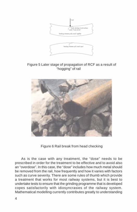
4
Figure 5 Later stage of propagation of RCF as a result of“hogging” of rail
Figure 6 Rail break from head checking
As is the case with any treatment, the “dose” needs to beprescribed in order for the treatment to be effective and to avoid alsoan “overdose”. In this case, the “dose” includes how much metal shouldbe removed from the rail, how frequently and how it varies with factorssuch as curve severity. There are some rules of thumb which providea treatment that works for most railway systems, but it is best toundertake tests to ensure that the grinding programme that is developedcopes satisfactorily with idiosyncrasies of the railway system.Mathematical modelling currently contributes greatly to understanding
5
the mechanism of crack development and the influences upon this,but it is not yet (and may never be) sufficiently sophisticated to allowa grinding strategy to be developed for a particular railway.
Grinding has at least two further influences on development anddetection of RCF, and accordingly on safety of the railway.
By removing irregularities, dynamic loads are reduced. Thebending waves in the rail that result from dynamic loading arecritical in the later stages of crack propagation (Figure 5).
The ultrasonic waves used in non-destructive testing (NDT)are reflected by surface cracking. If there are sufficiently severesurface cracks, it is impossible to inspect the rail reliably forinternal defects. By grinding the rail and removing surfacecracks, the rail can be inspected more reliably and thereforemore safely.
Fatigue cracks can (and often do) develop also in the bogie. Onmetro systems in particular, the dynamic loads arising from corrugationare often associated with premature failure of components, such asbolts, brake gear and even the bogie frame itself. Such failures canalso have catastrophic consequences: it is not unknown for tractionmotors to fall off and for brake gear to become lodged in points, therebypreventing their movement.
The success of rail grinding as a treatment of RCF, therebycontributing to a safer railway, is not only physically reasonable buthas also been widely demonstrated.
This can be achieved also with an overall cost saving. For example,the costs of rail grinding, rail replacement and the overall cost areshown in Figure 7 for a line in Sweden that carries primarily iron ore[1]. In 1997 routine grinding of the track commenced to give a high railprofile that relieved the area in which cracking typically occurred, givingrise to a dramatic and almost immediate reduction in rail defects andbroken rails.
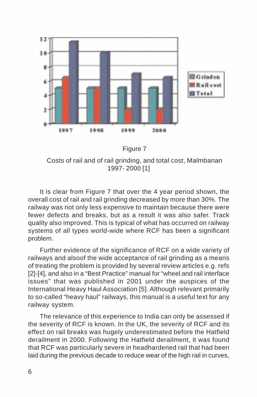
6
Figure 7
Costs of rail and of rail grinding, and total cost, Malmbanan1997- 2000 [1]
It is clear from Figure 7 that over the 4 year period shown, theoverall cost of rail and rail grinding decreased by more than 30%. Therailway was not only less expensive to maintain because there werefewer defects and breaks, but as a result it was also safer. Trackquality also improved. This is typical of what has occurred on railwaysystems of all types world-wide where RCF has been a significantproblem.
Further evidence of the significance of RCF on a wide variety ofrailways and alsoof the wide acceptance of rail grinding as a meansof treating the problem is provided by several review articles e.g. refs[2]-[4], and also in a “Best Practice” manual for “wheel and rail interfaceissues” that was published in 2001 under the auspices of theInternational Heavy Haul Association [5]. Although relevant primarilyto so-called “heavy haul” railways, this manual is a useful text for anyrailway system.
The relevance of this experience to India can only be assessed ifthe severity of RCF is known. In the UK, the severity of RCF and itseffect on rail breaks was hugely underestimated before the Hatfieldderailment in 2000. Following the Hatfield derailment, it was foundthat RCF was particularly severe in headhardened rail that had beenlaid during the previous decade to reduce wear of the high rail in curves,

7
and which had not been ground since installation (despite strongrecommendations being made to this effect by British Rail Researchthroughout the 1980s and into the early 1990s e.g. refs [6] and [7]).
A rough guide to the likely contribution of RCF to breaks anddefects in curves can be obtained by examining how many more railbreaks occur in the high rail of curves than in the low rail, regardlessof the cause that has been noted. The possible influence of corrugationand railhead irregularities on fatigue damage to bogies, traction motorsand brake gear can similarly be assessed only from a review of recordsand experience. Whether or not rail defects go undetected becausethey are “shielded” by RCF can also be determined only be examiningexperience on IR itself. A start could be made with this just by reviewingthe standards critically to determine the actions to be taken if railscannot be inspected with conventional NDT equipment.
India Railways would be an unusual if not unique system if railgrinding had no role to play in improving safety of the network bytreating RCF and corrugation, and thereby reducing rail defects, breaksand fatigue problems more generally. It is strongly recommended thatrecords and experience within IR be reviewed to ascertain whetherthere is a problem that could be treated by this means, and if so whatis its magnitude. The reward for this could be a railway that is notonly safer but also less expensive to maintain. Ignorance maysometimes be bliss, but peace of mind on a railway is more likely toarise from knowing not only the magnitude of a problem but also thatit is being treated satisfactorily.

8
REFERENCE
1 Grassie SL, Nilsson P, Bjurstrom K, Frick A and Hansson L-G, Alleviation of rolling contact fatigue on Sweden’s Malmbanan,Wear, 2002, 253, pp42-53
2 Grassie SL and Kalousek J, “Rolling contact fatigue:characteristics, consequences and treatments”, Procs of 6thInternational Heavy Haul Railways Conf., Cape Town, 1997,pp381-404
3 Cannon D, Edel K-O, Grassie SL and Sawley KJ, “Rail defects– an overview”, Fatigue and Fracture of Engineering Materialsand Structures, special issue on wheel / rail interface, 2003,26, pp865-886
4 Magel E, Roney M, Kalousek J and Sroba P, “The blending oftheory and practice in modern rail grinding”, Fatigue andFracture of Engineering Materials and Structures, special issueon wheel / rail interface, 2003, 26, pp921-929
5 “Guidelines to best practices for heavy haul railway operations:wheel and rail interface issues”, Intnl Heavy Haul Association,May 2001
6 Clayton P and Allery MBP, “Metallurgical aspects of surfacedamage problems in rails”, Canadian Metall Q., 1982, 21, pp31-46
7 Frederick CO, “Future rail requirements”, in JJ Kalker et al(eds), “Rail quality and maintenance for modern railwayoperation”, Kluwer Academic Publishers, Netherlands, 1993,pp 3-14
Vinod
Placed Image

1
3X TAMPER- MODIFICATIONS ON SCR
B. DEVA SINGH*
SYNOPSIS
Problems were encountered in the tamping units of 3X Tempersleading to frequent breakdowns on S.C. Railway. Field engineers werereluctant to utilise the machine as performance was uncertain. Expertsof OEM have carried out modifications, but they have resulted only insome temporary improvement and the problems persisted to a greatextent. Problems were studied in house by SCR personnel andmodification in hydraulic circuit was carried out which lead to drasticreduction in failure, thereby substantially improving both program andreliability.
S.C. Railway has also developed several spares required foroverauling of Temping unit indigeneously leading to substantial savings.The paper describes the modification in hydraulic circuit carried outon S.C. Railway and spares developed indigeneously.
1.0 INTRODUCTION
1.1 Packing of track is the mostimportant act iv i ty of t rackmaintenance. Indian Railwaysstarted mechanised maintenanceof track in the Sixt ies withUniversal Tamper (UT), which wascapable of tamping one sleeperat a time.
In view of ever increasing trafficand gradual reduction of time slot between two trains, Duomaticmachines, capable of tamping two sleepers at a time wereintroduced. Gradually 09-32 series continuous action machine(CSM) were introduced in the Nineties.
1.2 09-3x series continuous tamper, capable of tamping threesleepers at a time, was introduced in S.C.Railway during August2000.
* Chief Track Engineer, South Central Railway, Secunderabad
2
2.0 SPECIAL FEATURES OF 3X TAMPER
2.1 Special Features of 3X Tamper over 09-32 Series CSM are:
It is capable of tamping three sleepers at a time. It can also beused for tamping single sleeper at a time.
3X Tamper is equipped with laser system for correcting thealignment on straight track. The transmitter (Laser Gun) ismounted on a trolley, which is to be placed on the track duringtraffic block according to the requirement. The receiver (LaserReceiver) is a splash proof unit fixed with the screws on thechassis of the machines under the front cabin. The receiverreceives the signals from the laser gun and feeds the same tothe control unit of the machine. Normally a distance of 250-300meters is selected between the transmitter and the receiver.
The machine is highly powerful and capable of lifting/slewing thetrack upto 150mm irrespective of ballast resistance.
The rated progress of tamping is 1.6 km per effective hour.
3.0 PERFORMANCE ON S.C.R.
3.1 In order to get best output in a traffic block there was harmonyamong traffic and engineering officials with an understanding thatthe blocks must be made available to the machine as and whenrequired. Temporary single line (TSL) working were introduced onGroup ‘A’ routes to give longer blocks. The results were rewardingand highest records of tamping were set where in best progress perday of 19 kms and best progress per month of 250 km were achieved.
4.0 PROBLEMS OF TAMPIMG UNITS
4.1 Experience on SCR: Initial enthusiasm apart, there werefrequent problems in the tamping units in early stages itself.The machine was not available for blocks quite often due tofrequent breakdowns. Even though Service Engineers of OriginalEquipment Manufacturer (OEM) attended the machine very oftenduring warranty, there was little improvement. The failurescontinued to an extent that some of field engineers were reluctantto utilise the machine, as the performance was uncertain.Meanwhile the issue was taken up with M/s Plasser (India).Teams comprising several experts of OEM were deputed to the
3
machine. The personnel of OEM carried out several modificationsto the hydraulic system at different times. Though there used tobe some improvement temporarily, the problems persisted to agreat extent. Following instances of major failures happened onthe machine Over a period of about two years:
Tamping Units: 45 instances TOTAL failures: 51
Tamping unit and related hydraulic circuit accounted for 90% ofthe total failures.
4.2 Experience on Other Zonal Railways: The experience on otherzonal railways was not any different either. The experts ofM/s Plasser & Theurer, Austria visited the 3X-Tampers deployedin NR, WR & SER who made a report on the failures.
“A general conclusion, which can be drawn from this reportis that the machines have been used intensively, probably morethan comparable machines elsewhere in the world, however, thatthe effort to achieve a high production is not matching the effortfor adequate maintenance. According to the readings for tampinghead insertions, engine hours and mileage done, the distancesworked by these machines within 2 to 2½ years corresponds to1700 to 2200 km of track treated, respectively to 850.000 to1.150.000 tamping head insertions. In their environmentmachines usually are overhauled annually (during the winterseason) but in any case after 400.000 latest 600.000 tampinghead insertions. On the machines visited, absolutely necessaryrepairs had been carried out, however, on none of them anygeneral overhaul had been done.”
In view of the excessive use on the one hand and lackingadequate overhaul on the other, some of the units are in a reallyrun-down condition and it has to be expected that they will shortlybe beyond economical repair.
5.0 ANALYSIS OF FAILURES
5.1 A critical analysis of failure suggests that the conclusion israther simplistic and tend to put a heavy financial burden onthe user for trouble free working of the machine. True, timelyoverhaul is necessary which, as indicated, corresponds to800-1200 kms and 9-10 months period at expected output. It isnoteworthy in this context that the cost of overhauling thetamping unit with OEM spares is estimated to the tune of

4
Rs.1.5 crore. The unit cost of tamping on this count alone worksout to Rs.1.5 lakh per km, which is prohibitively costly.
5.2 Credible explanation is not available for the incessant failures,which hindered proper utilisation of the machine right frombeginning when the systems were new. Further, the type offailures/breakages was unprecedented as there has been a longexperience of 10 years with CSM tamping units. The remedy,therefore, seemed too elusive. The attentions given by the OEMwere found lacking in content in the wake of results. The tampingunit and related hydraulic circuit were studied in terms of causeand effect.
6.0 HYDRAULIC CIRCUIT OF 3X MACHINE
6.1 The tamping units of 3X tamper are provided with 4 units withprovision to tamp 3 sleepers at a time. Small squeezing cylinderswith reduced piston stroke pack the middle sleepers. This is toensure foul free movement of adjoining small squeezing cylinders’piston assemblies.
6.2 Normally the squeezing cylinders operate on differentialpressures. Rod side pressure is high since the effective area onwhich the pressure applied is less. Piston side pressure is lowbut applied over a larger area to obtain desired force. This pressureis continuously applied to prevent internal movement of pistonassembly inside the cylinder barrel due to vibration of tampingunit and this is known as counter pressure.
6.3 In CSM each sleeper is packed with a pair of one big and onesmall squeezing cylinder. Latter is known as closing cylinderdue to its lesser linear stroke. In this system the squeezing anddisplacement of ballast for packing under the sleeper is donelargely by big squeezing cylinder. However the role of smallsqueezing cylinder is mainly to prevent escaping of packed ballastfrom small arm side and this action is known as closing.
6.4 But in case of 3x tamper the center sleeper in each set of3 sleepers, is packed on both sides by small squeezing cylinders.
i) So it becomes essential that in the brief squeezing time, fulland positive packing is done under middle sleeper on parwith adjoining sleepers packed by big squeezing cylinders.This phenomenon necessitates operation of full stroke invery small period of time by small squeezing cylinders. To
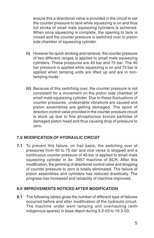
5
ensure this a directional valve is provided in the circuit to setthe counter pressure to tank while squeezing is on and thusfull stroke of small male squeezing cylinders is achieved.When once squeezing is complete, the opening to tank isclosed and the counter pressure is switched over to pistonside chamber of squeezing cylinder.
ii) However for quick stroking and retrieval, the counter pressureof two different ranges is applied to small male squeezingcylinders. These pressures are 40 bar and 75 bar. The 40bar pressure is applied while squeezing is on and 75 bar isapplied when tamping units are lifted up and are in non-tamping mode.
iii) Because of this switching over, the counter pressure is notconsistent for a movement on the piston side chamber ofsmall male squeezing cylinder. Due to these fluctuations ofcounter pressures, undesirable vibrations are caused andpiston assemblies are getting damaged. The spool ofdirection control valve provided in the counter pressure circuitis stuck up due to fine phosphorous bronze particles ofdamaged piston head and thus causing drop of pressure tozero.
7.0 MODIFICATION OF HYDRAULIC CIRCUIT
7.1 To prevent this failure, on trail basis, the switching over ofpressures from 40 to 75 bar and vice versa is stopped and acontinuous counter pressure of 40 bar is applied to small malesqueezing cylinder in 3x- 3957 machine of SCR. After thismodification, the jamming of directional control valve and droppingof counter pressure to zero is totally eliminated. The failure ofpiston assemblies and cylinders has reduced drastically. Theprogress has increased and reliability of machine improved.
8.0 IMPROVEMENTS NOTICED AFTER MODIFICATION
8.1 The following tables gives the number of different type of failuresoccurred before and after modification of the hydraulic circuit.The machine under went tamping unit overhauling (withindigenous spares) in base depot during 3-2-03 to 10-3-03.

6
8.2 Type and number of failures before and after modification ofhydraulic circuit over a period of two months in 3x- 3957 areenumerated in the table below. Due to reduction in failures perhour progress of tamping has escalated to higher levels andmonthly progress has further increased.
Type of failures Before After Remarks
a) Cover plate 5 0 Failures nilbolts shearing
b) Piston head 12 4 Reducedbolts shearing
c) Bush and piston 9 2 Reducedbreakage
d) Seals and 8 4 Reduced‘O’ ring failures
e) Male squeezing 3 1 Reducedcylinder failures
f) 35 bar pressure 15 0 Failures nildropping to zero.
Total failures 52 12 Significantimprovement
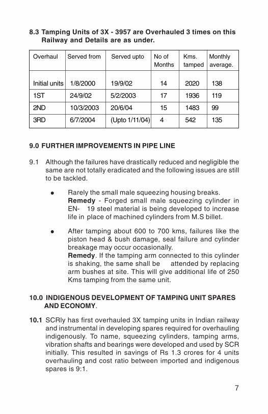
7
8.3 Tamping Units of 3X - 3957 are Overhauled 3 times on thisRailway and Details are as under.
Overhaul Served from Served upto No of Kms. Monthly Months tamped average.
Initial units 1/8/2000 19/9/02 14 2020 138
1ST 24/9/02 5/2/2003 17 1936 119
2ND 10/3/2003 20/6/04 15 1483 99
3RD 6/7/2004 (Upto 1/11/04) 4 542 135
9.0 FURTHER IMPROVEMENTS IN PIPE LINE
9.1 Although the failures have drastically reduced and negligible thesame are not totally eradicated and the following issues are stillto be tackled.
Rarely the small male squeezing housing breaks.Remedy - Forged small male squeezing cylinder inEN- 19 steel material is being developed to increaselife in place of machined cylinders from M.S billet.
After tamping about 600 to 700 kms, failures like thepiston head & bush damage, seal failure and cylinderbreakage may occur occasionally.Remedy. If the tamping arm connected to this cylinderis shaking, the same shall be attended by replacingarm bushes at site. This will give additional life of 250Kms tamping from the same unit.
10.0 INDIGENOUS DEVELOPMENT OF TAMPING UNIT SPARES AND ECONOMY.
10.1 SCRly has first overhauled 3X tamping units in Indian railwayand instrumental in developing spares required for overhaulingindigenously. To name, squeezing cylinders, tamping arms,vibration shafts and bearings were developed and used by SCRinitially. This resulted in savings of Rs 1.3 crores for 4 unitsoverhauling and cost ratio between imported and indigenousspares is 9:1.
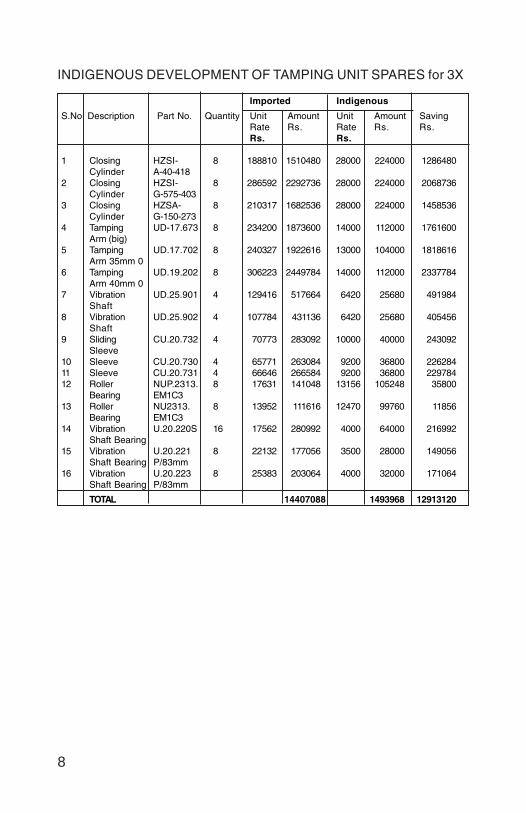
8
INDIGENOUS DEVELOPMENT OF TAMPING UNIT SPARES for 3X
Imported Indigenous
S.No Description Part No. Quantity Unit Amount Unit Amount SavingRate Rs. Rate Rs. Rs.Rs. Rs.
1 Closing HZSI- 8 188810 1510480 28000 224000 1286480Cylinder A-40-418
2 Closing HZSI- 8 286592 2292736 28000 224000 2068736Cylinder G-575-403
3 Closing HZSA- 8 210317 1682536 28000 224000 1458536Cylinder G-150-273
4 Tamping UD-17.673 8 234200 1873600 14000 112000 1761600Arm (big)
5 Tamping UD.17.702 8 240327 1922616 13000 104000 1818616Arm 35mm 0
6 Tamping UD.19.202 8 306223 2449784 14000 112000 2337784Arm 40mm 0
7 Vibration UD.25.901 4 129416 517664 6420 25680 491984Shaft
8 Vibration UD.25.902 4 107784 431136 6420 25680 405456Shaft
9 Sliding CU.20.732 4 70773 283092 10000 40000 243092Sleeve
10 Sleeve CU.20.730 4 65771 263084 9200 36800 22628411 Sleeve CU.20.731 4 66646 266584 9200 36800 22978412 Roller NUP.2313. 8 17631 141048 13156 105248 35800
Bearing EM1C313 Roller NU2313. 8 13952 111616 12470 99760 11856
Bearing EM1C314 Vibration U.20.220S 16 17562 280992 4000 64000 216992
Shaft Bearing15 Vibration U.20.221 8 22132 177056 3500 28000 149056
Shaft Bearing P/83mm16 Vibration U.20.223 8 25383 203064 4000 32000 171064
Shaft Bearing P/83mm
TOTAL 14407088 1493968 12913120

9
11.0 CONCLUSION
Retentivity of packing after modification.
It is doubted that this modification may affect the packing forceand retentivity. In small squeezing cylinder, the packing is doneby piston rod stroking inside the cylinder body. So by keepingthe counter pressure to 40 bar the original hydraulic circuitryconditions of tamping unit as designed remain same duringtamping operation and does not change the force applied on thearm or vibration RPM or stroke length of the piston into thecylinder while squeezing. This aspect was examined and it wasfound that the squeezing pressure, vibration and stroking of pistonrod remains same before and after modification.
3X-tamper costing Rs 7 Cr needs to be utilized properly formaking best use of traffic block and return on investment. Whiletimely overhaul is necessary, the problems encountered in theinitial stages needs to be addressed adequately by the OEM.As the basic problem of tamping unit persisted, innovative ideaswere used to modify the hydraulic circuit of the 3X- tamper. Themachine has since been working satisfactorily
Vinod
Placed Image

1
DEVELOPMENT OF COST EFFECTIVECONVEYOR BELT RIVETS AND JOINING OFOPEN-END BELTS REPLACING ENDLESS
CONVEYORS FOR FRM AND BCM
B.D.SEN*S. K. SINHA**
SYNOPSIS
The existing arrangement of conveyor belts in FRM and BCMposes lot of problems during their replacement. Eastern Railway hascarried out some modifications in the design which has madereplacement during maintenance much easier and cost effective. Thepaper describes the modifications carried out by Eastern Railway toachieve above objectives.
1.0 INTRODUCTION
Shoulder ballast cleaning & Ballast cleaning machine is animportant maintenance machine being used to keep the clean ballastbed for railway track and this is done mainly by Plasser makeFRM-80 & BCM RM-80 machine in Indian Railways. The existing designof conveyor belt in use in FRM & BCM has lot of problems. WhileFRM uses open ended & endless conveyor belt, BCM uses only endlessconveyor belt. Changing both of these type conveyor belt duringreplacement is difficult. Eastern Railway, to overcome this problemhas done certain modification in the existing arrangement making thereplacement during maintenance more cost effective & lesscumbersome .The paper deals with the modification done by EasternRailway to achieve this objective.
2.0 THE EXISTING DESIGN OF OPEN ENDED CONVEYOR BELT
This type of conveyor belt is in use only in FRM-80. FRMexcavates unclean ballast & carries it over to the screen mesh andafter screening, the cleaned ballast is fed into the track and differentspoil is discharged away from the track. Four types of conveyor belts
* AEN/TMC/E.Rly** SE/TMC/E Rly
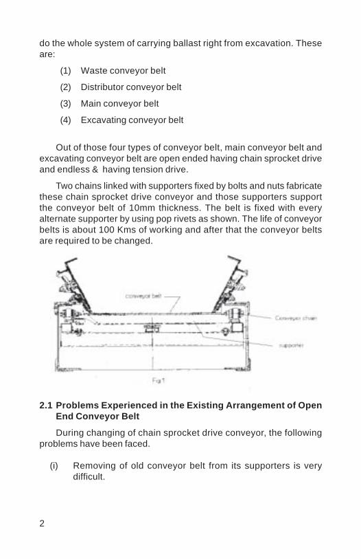
2
do the whole system of carrying ballast right from excavation. Theseare:
(1) Waste conveyor belt
(2) Distributor conveyor belt
(3) Main conveyor belt
(4) Excavating conveyor belt
Out of those four types of conveyor belt, main conveyor belt andexcavating conveyor belt are open ended having chain sprocket driveand endless & having tension drive.
Two chains linked with supporters fixed by bolts and nuts fabricatethese chain sprocket drive conveyor and those supporters supportthe conveyor belt of 10mm thickness. The belt is fixed with everyalternate supporter by using pop rivets as shown. The life of conveyorbelts is about 100 Kms of working and after that the conveyor beltsare required to be changed.
2.1 Problems Experienced in the Existing Arrangement of OpenEnd Conveyor Belt
During changing of chain sprocket drive conveyor, the followingproblems have been faced.
(i) Removing of old conveyor belt from its supporters is verydifficult.

3
(ii) Removing of old pop rivets from its supporters is trouble some.
(iii) To fix up new conveyor belt, it is required to be riveted withsupporters in new locations as the pop rivets can not be usedin the existing some locations. By using pop rivets, onesupporter becomes perforated for rivet holes.
(iv) Pop rivet is costly and not widely available.
(v) Requires special riveting gun, special drilling mechanism andhand drill machine.
(VI) Requires special skill for drilling and riveting.
2.2 Modification as done by E.Rly.
To overcome the above problems, Eastern Railway found a solutionby developing a simple designed rivet and washer replacing pop rivetequipped by OEM. It is very convenient to fix up and the life of suchrivet is not less than pop rivet. A simple designed rivet and washer isdeveloped as shown below
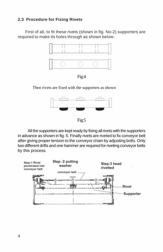
4
2.3 Procedure for Fixing Rivets
First of all, to fit these rivets (shown in fig. No-2) supporters arerequired to make its holes through as shown below:
Fig:4
Then rivets are fixed with the supporters as shown
Fig:5
All the supporters are kept ready by fixing all rivets with the supportersin advance as shown in fig. 5. Finally rivets are riveted to fix conveyor beltafter giving proper tension to the conveyor chain by adjusting bolts. Onlytwo different drifts and one hammer are required for riveting conveyor beltsby this process.

5
2.4 Advantages of This Alternative Method
i) Removing of supporters from damaged conveyor belt is easierfor its reuse.
ii) Removing of old rivets from supporter is easier.
iii) New rivets can be fitted in same locations of holes. So nofurther perforation takes place in supporters and that’s whythe life of supporters becomes more than double .
iv) Modified designed rivets are too cheap in comparison to poprivets and it is easy to manufacture by simple turning operationin lathe machine.
v) No need of special rivet gun, special drilling attachment, drillmachine and special skill.
vi) Machine down time is less to change conveyor belts thanthat of pop riveting.
vii) Alternative method of conveyor belt riveting with modified rivetsis cost effective.
2.5 Cost Analysis
Total No. of rivets required for one complete change =1300 Nos.
(A) Cost of one pop rivet =Rs 3400 (A) Cost of one modified rivetTotal cost of rivets =Rs 44,200/- = Rs 3.00
Total cost of rivets =3900/-
(B) Cost of supporters (B) NIL25% of total supporters are Total cost = A+B = Rs 3900/-rejected in case of pop rivetingcost of new supporters @ Rs 947/-(OEM’S AMC rate) =110 x 947/- =Rs 1,04,170/-Total cost = A+B = Rs 1,48,370/-
The above comparison clearly reveals that by adopting alternativeprocess of riveting conveyor belts Rs- 1,44,470/- can be saved in everychange.
6
3.0 REPLACEMENT OF END LESS CONVEYOR BELTS(TENSION DRIVE) BY OPEN END CONVEYOR BELTS USINGCOLD VULCANIZING METHODS
3.1 Present Arrangement
There are several sizes of end less conveyor belts used in severalconveying system in BCM and FRM.
Four endless conveyor belts of BCM are:
(1) Distributor conveyor/ Feeder conveyor = 02 Nos(2) Main conveyor = 01 No(3) Waste conveyor/ disposal conveyor = 01 No
And three conveyors of FRM are:
(1) Distributor conveyor/ feeder conveyor = 02 Nos(2) Waste conveyor/ disposal conveyor = 01 No
A great extent of technical difficulties arises during procurementof these conveyor belts because of endless and different sizes. Evensame type of belts of same type of machine differs in length inrespect of different machine. So each type of belt for each particularmachine is required to be kept in store to meet the demand at theearliest. This involves lots of investment, increases inventory andmoreover in case of long storing the quality of the materialdeteriorates as these are rubber items .
Secondly, fitment of endless conveyors is very difficult, so manydismantling works are involved in wearing of these conveyors and ittakes a lot of time with hard working. So down time of the machine ishigh approximately two to three days for one change.
All above problems arise due to its endless ness. So to avoid allproblems Eastern Railway has adopted to use open end conveyorbelts and made them endless by using cold vulcanizing method.Initially, open end conveyor belts are put in its position in machine atsite without any dismantling jobs and then open ends are madeendless by using cold vulcanizing method only in 24 hours, the coldvulcanizing joints give 100% strength, so down time can be reducedto 1/3rd of the normally taken .

7
3.2 Cold Vulcanizing and its Process :
It is a new concept of conveyor belt repairing, joining maintenance.
A specially formulated cold vulcanizing solution joins the beltswith some preparation within 3 to 4 hours down time. These are somereputed companies products available in market.
Mainly the vulcanizing solution is having two parts, one is basesolution and other is hardener. These two solutions are required to bemixed in certain ratio by weight as directed by the respectivemanufacturer. Generally the vulcanizing solution is available in 4 litresor 5 litres minimum pack with 4 to 5 bottles of hardener containingcertain weight of hardener.
Generally one bottle of hardener is mixed with one litre of basesolution. Pot life is normally one hour and curing time is 10 minutesin between coats subjected to humidity in the atmosphere. Two coatsare preferred and its coverage area is 6 to 7 Sq.Mt. per litre.
Details of effective geometry of joining conveyor belt by using coldvulcanizing solution are as follows:
W = Width of the belt, SL= Splice length = W/2 for 3 ply conveyor.L = Total Length of over lap = 1.6 W
8
3.3 Advantages of Using Cold Vulcanizing Solution:
(1) Procurement of end less conveyor of several sizes is notrequired.
(2) Fewer inventories.(3) Less investment in cenveyor belt head.(4) Less down time by higher productivity.(5) Less manpower.(6) Simple and easy job.
4.0 CONCLUSION:
Process of alternative rivets and riveting process is easier & doesnot require any rivet gun, special drilling arrangement, hand drillmachine and special skill. Moreover, this process does not damagesupporters. Overall it is cost effective. Also by adopting latesttechnology for joining conveyor belts, lot of problems related to joiningconveyor belt are eliminated. Cold vulcanizing process also reducesdown time to 1/3rd approximately. This process has been tested inBCM-321 & FRM-1873 which is currently working in Eastern Railway.
Vinod
Placed Image

1
PRECISION TOP TABLE SURFACING WITH TRACKSTABILIZATION USING THE DYNAMIC TRACK
STABILIZER
MUKESH KUMAR*
SYNOPSIS
The Dynamic Track Stabilizing machine has been in use, in theIndian Railways for over 10 years now but largely remains anunderutilized and often an ignored machine. The utility of this machineis commonly confined to faster relaxation of speed restrictions aftertrack maintenance, renewals and routine maintenance operations.
The inherent capabilities of this machine, is never exploited toits full potential and its importance gets belittled before other machineslike the fast track tampers and BCMs. Little it is known, that thismachine is also equipped with the same proportional leveling systemwhich forms the basis of working of the Tampers, in as much as thatthis machine can even be used for leveling of the track even after theTampers have done their job; and with greater precision and enhancedstability.
1.0 INTRODUCTION
With the advent of PSC sleepers ‘On-Track Tampers’ have becomethe mainstay of mechanized track maintenance. Restoration andcorrection of geometric parameters of the track is required after trackrenewals, ballasting and as routine maintenance. While this task isperformed by the tampers, the function of DTS is relegated to the secondaryrole of stabilization of track to ensure faster relaxation of SpeedRestrictions.
The fact that coupled together with the obvious benefits of mechanizedstabilization, the track geometry can be further ‘fine-tuned’ to perfectionis never realized. That this machine shall be equipped with a leveling
*Dy.CE/Track Machines,East Central Railway

2
system also forms part of the contract, under which this machine ispurchased. Even the benefits of stabilization with DTS are seldom givencare.
This paper endeavors to not only show-case the DTS as a machinemeant for precision top – table surfacing but also to reiterate and underlinethe importance of controlled track stabilization.
2.0 PRECISION TOP TABLE SURFACING
That the DTS can improve Track Geometry in general and achievedesign mode finishing of the track with cross level as per the inputs is notmuch known. The Dynamic Track Stabilizer comes with the sameproportional leveling system which is employed by the tampers. Unlikethe tampers the leveling chords are not distinctly visible but are providedunder the main deck and with the same arrangements of the front, middleand rear feeler rods and pendulums as in the tampers.
Whereas the tampers work on the general principle of ‘lifting thetrack to corrected geometry’, the DTS ‘settles the track to the correctedgeometry’ under controlled dynamic loading. The machine is equipped tofunction both in automatic and design mode apart from the constantpressure mode.
2.1 Variable or Automatic Mode:
This machine is invariably used in this mode. Working in this modethe machine reduces the errors of longitudinal level by a factor of 0.5 inaccordance with the ‘machine-ratio’ but the cross level values are copiedas they are. The settlement value can be pre-selected and is just like the‘general lift’ input given in the tampers but of course opposite in nature.
The cross level selector is switched in automatic mode. The frontpendulum reads the cross level of the track as left by the leading tamper.This becomes the target cross level value for the middle feeler rods. Thisis achieved through a distance encoder and time delay circuit, where thismeasured reading is transferred to the middle feeler rods in the actualworking area of the stabilizing units.
These cross level inputs are fed into the lowering circuit of the rail,opposite the basic rail. While the pre - selected settlement value is for thebasic rail the signals of the super elevated rail overrides the pre - selectedvalue for the other rail.
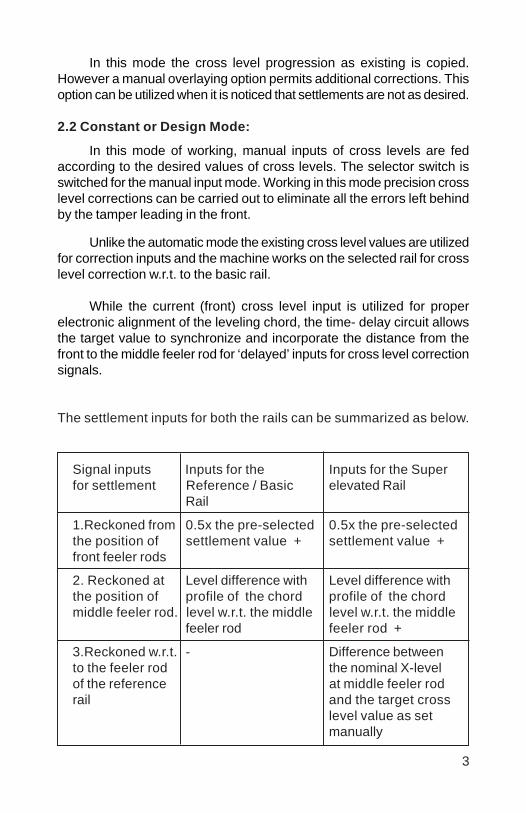
3
In this mode the cross level progression as existing is copied.However a manual overlaying option permits additional corrections. Thisoption can be utilized when it is noticed that settlements are not as desired.
2.2 Constant or Design Mode:
In this mode of working, manual inputs of cross levels are fedaccording to the desired values of cross levels. The selector switch isswitched for the manual input mode. Working in this mode precision crosslevel corrections can be carried out to eliminate all the errors left behindby the tamper leading in the front.
Unlike the automatic mode the existing cross level values are utilizedfor correction inputs and the machine works on the selected rail for crosslevel correction w.r.t. to the basic rail.
While the current (front) cross level input is utilized for properelectronic alignment of the leveling chord, the time- delay circuit allowsthe target value to synchronize and incorporate the distance from thefront to the middle feeler rod for ‘delayed’ inputs for cross level correctionsignals.
The settlement inputs for both the rails can be summarized as below.
Signal inputs Inputs for the Inputs for the Superfor settlement Reference / Basic elevated Rail
Rail
1.Reckoned from 0.5x the pre-selected 0.5x the pre-selectedthe position of settlement value + settlement value +front feeler rods
2. Reckoned at Level difference with Level difference withthe position of profile of the chord profile of the chordmiddle feeler rod. level w.r.t. the middle level w.r.t. the middle
feeler rod feeler rod +
3.Reckoned w.r.t. - Difference betweento the feeler rod the nominal X-levelof the reference at middle feeler rodrail and the target cross
level value as setmanually

4
Monitoring of the corrected cross level values is possible with thedigital display of the values of the rear pendulum. However to achievedesign mode functioning a comprehensive understanding of the interplayof the following parameters is necessary.
Amount of the pre-selected settlement, which also governsthe vertical loading pressure.The vertical loading pressureThe servo current for flow valves for both the railsThe ‘Gain’ given in the potentiometers for both the railsThe vibrating frequencySpeed of working.
(The loading pressure determines the settlement at both andultimate correction of track geometry. The loading pressure isdependant upon the pre-selected settlement, the gain given and thecurrents from the ‘transducers’. The servo current is also indicative ofthe vertical loading pressure).
Basically the control over desired settlement is through the ‘Gain’for both the rails. If desired settlements are not achieved or if thecross level corrections are not being achieved then of course the‘settlement’ can be reduced.
This however is depends upon the looseness of ballast structureand height of the preceding lift given by the tamper.
Following settings can be adopted to achieve design mode working.
Settlement 10 mmLoading pressure 60- 80 bar‘Gain’ 50 %Frequency 30 – 35 HzSpeed ‘matching with the tamper’Super elevation inputs as desired for the curve/
straight trackNote:
However it should be borne in mind that the design mode working/correction of track parameters is only limited to ‘Fine- tuning’ or ‘precisionworking’. The range of correction is thus restricted within the achievablesettlement range of the track, which at the maximum is 20 – 25 mm.Cross level corrections within +/- 6 mm from the existing super elevationcan be possibly carried out with proper machine settings.

5
A typical lifting and lowering sequence of track leading to restoration ofthe original rail level with final round done in ‘precision mode’.
Maintenance Change in Balance level Remarksoperations level (mm) of Rail Top
(mm)
Before commen- 0 Starting levelcement of work before screening
-Expected lowering - 100 Deep Screeningdue to screening by BCM-BCM lift input + 80-Expected settlement - 20
- 40 - 40
-Lift given in initial +40 DTS working inround of tamping automatic mode-Expected Settlement - 20 with leveling-Settlement by DTS - 20 - 40 switched off
0
-Lift given in 1st DTS working inround of tamping constantafter ballasting + 50 pressure-Expected Settlement - 15 working mode-Settlement by DTS - 20
+ 15 - 25
-Lift given in 2nd + 50 DTS working inround of tamping automatic mode-Expected Settlement - 15 with leveling-Settlement by DTS - 20 switched on
+ 15 - 10
-Lift given in final + 25 DTS working inround of tamping design mode-Expected Settlement - 5 -Settlement by DTS - 10
+ 10 0 Final Level

6
During the entire operations care as regards DTS should be takenregarding
Unforeseen standstills of the machine.Foreseen standstills of the machineStabilization of tracks adjacent to buildingsStabilization of track over bridgesStabilization of track in tunnels (prohibited)
2.3 Case Study
CSM 923 and DTS 347 worked in DN Mainline Raghunathpur andTurigang stations of Danapur Division of ECR on 29.07.2004. Stabilizationby DTS with a manual overlay of 2 mm cross level input was tried inbetween kms 634/ 22 and 634/ 20. Stabilization in Design mode withCross Level input as ‘0’ was tried in between kms 634/ 20 and 634/ 18.
The comparative results can be seen in this table
Operation Xls taken at every 5th sleeper1st Xls after tamping 2L 2L 0 2L 4L 0 0 0 2L 2L 4L 4L 2L 2Ltrial by CSM between
634 / 22 - 20
Xls after Stabilization 2L 2L 2L 0 2L 2L 0 0 0 2L 2L 2L 0 0with DTS with amanual overlayof 2R
2nd Xls after tamping 2L 0 0 2R 4R 0 0 2L 2L 4L 2L 0 2R 2Rtrial by CSM between
634 / 20 – 18
Xls after Stabilization 0 0 0 0 2R 0 0 0 0 0 2L 0 0 0with DTS in Designmode (xl = 0)
The degree of corrections carried out in both the trails is graphicallydepicted in the following diagrams where the quality of top table surfacingdone in design mode of surfacing can be appreciated.

7
3.0 STABILIZATION
3.1 Need For Stabilization:
The DTS is used as the very name suggests stabilizing thecorrected track. The unavoidable reduction of the track’s resistanceto lateral displacement after the tamping requires speed reductionsuntil the track has settled again under the impact caused by the loadof a certain number of passing trains.
Settlement of the track is achieved artificially or by traffic loading,which occurs due to the movement and the rearrangement/realignment ofthe ballast stones. The resulting reduction in voids governs the degree ofconsolidation of the ballast and the settlement of the track.
3.2 Adverse Effect of Rolling Stock
Over unstable ballast structure, contrary to the DTS, rolling stockacts very differently on the permanent way,
By introduction of uneven settlements.
By magnifying some of the inherent defects in track geometry.
This leads to a rapidly progressive deterioration of the trackgeometry. On loose ballast the traffic loading causes high forces actingon the touching points and edges of the ballast stones, resulting incrushing. There then occurs a disproportionately high amount of the
8
fine granulates, which needless to mention impair drainagecharacteristics and effective ballast cushion.
3.3 Adverse Effects Caused By Tampers
Tampers work on the principle of elevating the track to correctedgeometry. In the process an inherent stability is introduced in thetrack structure by way of.
Orientation of the aggregates becomes unstable (longerdimension tending to be in upward direction).The consolidated structure of the ballast is completely shakenup.Track lifting introduces more voids between the sleepers, inwhich the compacted ballast tend to loosening up withpassage of traffic.The sleeper to ballast contact surface is disturbed.
There is reduction in surface to surface contact in the ballastwhich causes high concentration of stresses and faster deteriorationof the aggregates.
3.4 Advantages of Stabilization
The Dynamic Track Stabilizer works on the principle of controlledsettlement of the track to corrected geometry. The existing instabilitiesintroduced by action of tamping are removed as the sleepers are rubbeddown into the ballast bed whilst plastic state of ballast is achievedunder forced vibrations.
With the “controlled” settlement by uniform dynamic action onlyaround 30 % maximum of the forces occurring due to the traffic loadare transmitted and therefore the ballast is not unduly stressed. Theadverse affects caused by the tampers and subsequent damagecaused by rolling stock is minimized.
The benefits of the controlled, dynamic stabilization can besummarized as:
Elimination of the uneven initial settlements which are causedby the uneven impact of passing trains.Conservation of the corrected track geometry.
9
Building up of a homogeneous structure of the ballast bed,Raising the resistance to lateral displacement and therebyeliminating chances of misalignment.Enhancing safety against track bucklingLonger service life of the track.Faster relaxation of the speed restrictions.
4.0 RECOMMENDATIONS
Proper upkeep and calibration of the machine is necessary if themaximum utilization of the machine is desired. It is also importantthat the rail level profile is meticulously maintained so that the liftingand lowering of the track following runs of tampers and DTS can bemonitored to work out the proper inputs for achieving the desiredresults. After all the DTS needs a certain range of cushion ofunconsolidated ballast to achieve the desired track parameter.
Secondly an in-depth understanding of the functioning of thismachine is required without which the control parameters governingthe inputs given to the machine cannot be judiciously worked with.
5.0 CONCLUSION
The utility of DTS is an established fact beyond doubt. A trackstructure with a lasting ‘top- table surface’, finished to the finest levelsand formed over a consolidated bed of stabilized ballast is preciselywhat we need and the most effective way, would be to utilize the DTSto its full potential.
References:
1. The technology of Dynamic Track Stabilization by M/s Plasser&Theurer
2. DTS operating manual3. Catalogued electrical drawings of DTS4. Indian Railway Track Machines Manual
Vinod
Placed Image

1
* Chief Bridge Engineer, N.Railway** Executive Director/QA,RDSO*** Dy. CE/(Con), N. Railway
H.K.JAGGI* S.K.RAINA**
P.K.GUPTA***
MECHANISED MANUFACTUREAND
LAYING OF BLANKET IN RAILWAY EMBANKMENTS
SYNOPSIS
Almost all the existing formations of Railways were constructedmany decades ago without any consideration of soil strength. Dueto phenomenal increase in the axle loads, traffic and speed of trainsin recent years, large lengths of existing formations are showingsigns of distress/instability. Improvement in top layer of railwaysub-grade by providing suitably designed sub-ballast layer, calledblanketing is therefore essential to withstand higher stresses.
Specification of blanketing material have been laid down byRDSO. Experience has shown that required material conformingto these specifications is not available in natural form at most of theplaces. Non-availability of blanketing material as per requiredspecifications has become a bottleneck in completion of a numberof projects of new lines & doublings.
Work of new line from Chandigarh to Ludhiana was taken upfor execution during the year 2000. On detailed survey of the areait was found that none of the natural material available in the vicinityof the project conforms to the specifications of blanketing material.Trials were made for obtaining blanketing material by blending twoor more natural materials. This was also found to be unsuccessfulas uniform blending was not possible by manual mixing andmechanical mixing would not be economically viable. After all theefforts to get material of consistent specifications turned futile, aninnovative method of manufacturing blanketing material bymechanical crushing of stones was tried. After a number of trialswith different combination of sieves and crushing pressures, it waspossible to mechanically produce blanketing material as perspecifications. This has been successfully laid over about 40 kmsof track on Chandigarh – Ludhiana new line.
2
This paper mainly deals with the method of manufacturing ofblanketting material, trials conducted during manufacturing ofblanketting materials and the procedure of laying and compaction.Results of compaction and gradation curves of different trials arealso being discussed.
1.0 INTRODUCTION
Almost all the existing formations on core routes wereconstructed many decades ago without any design considerationof soil strength. Due to phenomenal increase in the axle loads,traffic and speed of trains in recent years, large lengths of existingformations are showing signs of distress/instability. Lengths of suchstretches are likely to increase in future with introduction of heavieraxle loads. Improvement in top layer of Railway sub-grade byproviding suitably designed sub-ballast layer/Blanketting is essentialto withstand higher stress.
Blanket is a layer of adequate thickness of selected granularmaterial laid between ballast & subgrade.
2.0 ROLE OF BLANKET LAYERS
Following are the main functions of the blanket layer
1. Improving the bearing capacity by modifying the stiffness andachieving a better distribution of transmitted loads on the sub-grade soil, thus preventing ballast penetration into theformation.
2. Reduction of induced stresses on the top of sub-grade to atolerable level.
3. To prevent mud pumping, and fouling of ballast by upwardmigration of fine particles from the sub-grade.
4. To prevent damage of sub-grade by ballast.
5. Shedding surface water from the ballast and draining awayfrom the sub-grade.
6. Protection of sub-grade against erosion and climatic variation.

3
3.0 CHARACTERISTIC OF BLANKET LAYER
1. Should be impervious enough to drain out rainwater falling overit to prevent softening of subgrade soil.
2. Should be reasonably pervious to allow full dissipation of porepressure within the blanket.
3. Should have sufficient strength to withstand the trainloadwithout appreciable plastic deformation and there should beno heaving under repetitive loading.
4. Should be easily compacted to have minimum plasticdeformation and should not get eroded during rains.
5. Should not cause mud pumping under repetitive loading.
4.0 SPECIFICATIONS OF BLANKETTING MATERIAL.
Specifications of blanket material on Indian Railways wereinitially issued as per “Guidelines of Earthwork – 1987” by RDSO.These specifications are as below:
1. No skip grading to be allowed.
2. The blanket material should be coarse, granular and from hardrock.
3. The material should have small quantity of fines. If the finesare plastic, the percentage of fines i.e. particles up to 75microns, can be up to 5%. If fines are non-plastic, these canbe up to 12%.
4. Uniformity coefficient (D60/D10), in no case should be less than4. Preferably, it should be more than 7.
5. The coefficient of curvature (D230 /D60 x D10), to be within 1 & 3.
In addition to above specifications, gradation curve of thematerial should lie between two enveloping curves as shown inAnnexure I.
Specifications of blanket material for Indian Railways havenow been included in para 4.3.4 of “Guidelines of Earthworkin Railway Projects No. "GE G-1, July-2003". Two sets ofenveloping curves for blanket material have been covered inthese specifications. One of these curves is almost identical to

4
the enveloping curve given in the “Guidelines of earthwork-1987”, while other curve is for coarser blanket material.
5.0 RDSO STUDIES OF 2000-2001
During 2000-2001, RDSO carried out suitability tests on morethan 150 naturally occurring soil types. As reported in Report no:GE-37 in May 2001, it was concluded that only 22 out of 150expected blanket materials passed the required specifications. Only33% of the other samples were close to the specifications, while45% of these were totally unsuitable. Hence, if a project site is notlocated close to the source of naturally occurring blanket material,machine manufacturered i.e. crushed rock material could be theonly desirable alternative.
6.0 SUITABILITY OF MATERIAL FOR BLANKETTING
6.1 The most natural choice for Blanket material is river bed whichis mostly coarse sand mixed with various size of boulders.However following are main difficulties encountered in usingriver bed material for Blanketting.
a) INCONSISTENCY:
Material varies widely and it is difficult to meet thespecifications especially coefficient of curvature whichshould be between 1 & 3.
b) ERODABILITY:
Generally this material is prone to erosion resulting intoserious damage to embankment during rainy season.Confinement of this material by providing clayey soil onboth sides and sand / boulder drains has been tried but itis difficult and time consuming process.
c) AVAILABILITY.
Most of the time, this material is not available near toprojects which increases the cost substantially.
6.2 Blanketting with moorum has been tried at a number of placesbut availability and erosion - proneness of this material areserious problems.
6.3 Due to non availability of the blanket material conforming tospecifications in natural form, various methods of blending of

5
different materials have been tried. However, these have alsonot been found very successful as it is very difficult to achieveuniform blending with manual mixing. Mechanical mixing leadsto very high cost.
7.0 CHANDIGARH-LUDHIANA NEW B.G. RAIL LINK PROJECT
The work of new B.G. Rail Line from Chandigarh to Ludhianawas taken up for execution during the year 2000.
7.1 Selection Of Blanketing Material
7.1.1 Natural material
On detailed survey of the area, it was found that none of thenatural materials available in the vicinity of the project conforms tothe specification of blanketing material.
Samples from river bed material near Burj-Kotiyan werecollected and particle size distribution (PSD) was checked. It wasfound that the naturally occurring river bed material is only partlysuitable, and could be made fit for use by blending with some othermaterial. Since no other sand/gravel type material was availablefrom nearby rivers, this option was not feasible.
7.1.2 Highway subgrade
Different materials being used for construction of Highways werealso examined. Sub base of granular material duly compacted ofapprox. 30 cm thickness is being laid in National Highway and otherimportant roads over the sub grade.
In the construction of National Highways in the vicinity ofChandigarh, material for Granular Sub base is being obtained frombed of river Ghaggar.
As per specification of MOST, the material to be used for thework shall be natural sand, moorum, gravel crushed stone orcombination thereof depending upon the grading required. Materiallike crushed slag, crushed concrete, brick metal and Kankar maybe allowed only with the specific approval of the Engineer. Thematerial shall be free from organic or other deleterious constituents,conform to one of the three grading ( given by MOST) given in thefollowing table.

6
7.1.3 The set of enveloping curves (shown in Annexure-I) as per“Guidelines for earthwork 1987” issued by RDSO was the criterionfor passing of blanket material for Chandigarh Ludhiana B.G. RailLink. Grading of Blanket material for Railway work as per this setof enveloping curves has been compared with gradings of granularsub base of national Highway (As discussed in para 7.1.2 above) inannexure II, III & IV. Comparison of the important parameters ofCu (Coefficient of uniformity) and Cc (coefficient of curvature) ofthe material permitted for granular sub base and material forblanketing is as under:
Item Granular sub-base of roads Requirementof Blanketmaterial.
Grading I Grading II Grading III
Range of 25 to 350 30 to 43 15 to 40 > 7coefficient ofuniformity
Co-efficient of 4.02/1.36/1.94 1.09/0.73/1.07 0.56/0.54/0.76 1 to 3curvature of lefthand curve/ave--rage curve/righthand curve
Sieve Designation Percent by weight passing the sieve
Grading 1 Grading II Grading III
90 mm 100 100 100
63 mm 90-100 90-100 90-100
37.5 mm 75-95 78-100 82-100
22.4 mm 65-90 68-99 75-100
5.6 mm 39-72 44-91 53-100
600 micron 14-38 16-56 22-68
75 micron 0-20 0-25 0-30

7
It is observed from the above table that none of the grading ofgranular sub base completely fits into the specification of blanketingmaterial as it is not possible to achieve the value of coefficient ofcurvature. Moreover function of the granular sub base is differentthan blanketing material as granular sub base is enclosed on allsides and therefore not susceptible to erosion, though method ofspreading and compacting of granular sub base is identical tospreading and compacting of blanketing material.
7.2 Blanket Material by Mechanical Crushing of Stones
After all the attempts to obtain natural material for blankettingfailed, option to manufacture blanket material by artificial meanswas explored. In view of the availability of crushers within areasonable distance from the project alignment, it was decided totry machine crushed blanket material . Easiest method tomanufacture blanket material was considered to be one whichinvolved only one operation. 2/3 crushers near River Ghaggar invi l lage Burj Kotian near Chandigarh were requisit ioned tomanufacture required blanket material by crushing of stones.Before starting the manufacture of the material, analysis of differentcombination of crusher dust and 10mm stone grit was carried out.Both these materials are available in plenty at crushers. Graphicalrepresentation of these results vis-a-vis enveloping curve ofblanketting analysis is shown in Annexure V. Values of variousparameters for different combinations of crusher dust and 10mmstone grit are as under.
Sam Colour Ratio D60 D30 D10 Cu Cc Fine-ple -nessNo.
Gradat Crus 10mm-ion -her stoneCurve dust grit
1 Red 30 70 6.35 1.55 0.11 57.73 3.44 8.04
2 Green 40 60 5.40 0.70 .075 72.00 1.21 10.72
3 Purple 50 50 3.45 0.37 .055 62.73 0.72 13.40
4 Yellow 60 40 1.98 0.26 0.046 43.04 0.74 16.08
5 Blue 70 30 1.50 0.18 0.038 39.47 0.56 18.76
8
From above, it can be seen that coefficient of uniformity couldbe achieved in all 5 different combinations. However, coefficient ofcurvature was achieved only when 10 mm stone grit and crusherdust was mixed in the ratio of 60:40.
Initial trials were done on the crusher site of M/s. Bathinda StoneCrusher, Burj Kotian. Screening of crusher dust during theproduction of 10mm stone grit was stopped and the sample of10mm stone grit mixed with crusher dust was taken. The samewas got tested from M/s. Uppal Lab in Chandigarh. This samplewas found to contain 39% 10mm stone grit and 61% crusher dustand its co-efficient of uniformity was found to be 67.6 and coefficientof curvature was found as 0.52. However, it was observed thatproduction of blanket material with 10mm stone grit and crusherdust in the ratio of 60:40 should be possible by adjustments ofcrusher jaws, changing the combination of sieves and by usingdifferent sizes of raw material.
Only minor relaxation required in the specification was that thegradation curve will cross the enveloping curve on right hand sideby a slight margin.
First contract for carrying out blanketting for CDG – LDH B.G.Rail Link was awarded to M/s. Amarnath Aggarwal ConstructionCompany, Panchkula. During the transportation of the material, itwas observed that there is a possibility of segregation of crusherdust and stone grit if the material is transported in dry condition.Therefore, transportation of the material in wet condition was donewhich has been found to be very successful. This wet material isdirectly laid on the site and can be compacted with combination ofvibratory roller and static roller. This makes the whole operationvery quick and easy. However, transportation of the material in wetcondition adds to the cost slightly.
7.3 Procedure for Execution
The material is being transported in wet condition from crushersite directly to the embankment. Compaction is being doneimmediately after receipt of material as the operation of wateringcan be saved. Testing of the material is done by taking samplefrom the finished bed of blanketting. Since there is a possibility ofa little segregation of material, samples for checking the parametersare being obtained from four places and then mixed thoroughly.
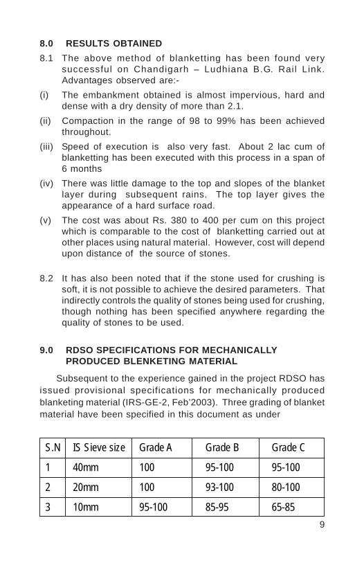
9
8.0 RESULTS OBTAINED8.1 The above method of blanketting has been found very
successful on Chandigarh – Ludhiana B.G. Rail Link.Advantages observed are:-
(i) The embankment obtained is almost impervious, hard anddense with a dry density of more than 2.1.
(ii) Compaction in the range of 98 to 99% has been achievedthroughout.
(iii) Speed of execution is also very fast. About 2 lac cum ofblanketting has been executed with this process in a span of6 months
(iv) There was little damage to the top and slopes of the blanketlayer during subsequent rains. The top layer gives theappearance of a hard surface road.
(v) The cost was about Rs. 380 to 400 per cum on this projectwhich is comparable to the cost of blanketting carried out atother places using natural material. However, cost will dependupon distance of the source of stones.
8.2 It has also been noted that if the stone used for crushing issoft, it is not possible to achieve the desired parameters. Thatindirectly controls the quality of stones being used for crushing,though nothing has been specified anywhere regarding thequality of stones to be used.
9.0 RDSO SPECIFICATIONS FOR MECHANICALLYPRODUCED BLENKETING MATERIAL
Subsequent to the experience gained in the project RDSO hasissued provisional specifications for mechanically producedblanketing material (IRS-GE-2, Feb’2003). Three grading of blanketmaterial have been specified in this document as under
S.N IS Sieve size Grade A Grade B Grade C
1 40mm 100 95-100 95-100
2 20mm 100 93-100 80-100
3 10mm 95-100 85-95 65-85

10
S.N IS Sieve size Grade A Grade B Grade C
4 4.75 mm 92-99 70-92 43-70
5 2 mm 65-90 46-65 22-46
6 600 micron 33-50 22-33 08-22
7 425 micron 28-40 18-28 05-18
8 212 micron 16-27 10-16 00-10
9 75 micron 00-12 00-10 00-08
Material of grade A in above table is almost similar tospecifications of blanket material given in “Guidelines of earthwork-1987”. Grade B and Grade C are for coarser materials.
10.0 COST ASPECTS
Cost analysis of production of blanket material at Chandigarhshows that the material can be produced with a nominal additionalcost. There is generation of 40mm-65 mm ballast as the mainproduct, which is usable in railways/road works. Blanket materialbecomes available as a by-product. If crushing of stones is donein an appropriate ratio which avoids wastage of quarry dust, thecost of production can be reduced further.
11.0 CONCLUSION
It is obvious that mechanically produced material makes verygood blanket material, which can be easily transported, easilyspread and easily compacted, to the desired levels. One can expectto achieve the best desired properties. Moreover, its production isfinancially viable, considering the consistency of results and speedof execution.

11
12.0 RECOMMENDATIONS
Based on the experience gained in executing the blanketingwork on Chandigarh-Ludhiana B.G. Rai l Link, fol lowingrecommendations are made:
(i) Specifications of blanketting should contain the specificationsof stone to be used which can be similar to stone being usedfor ballast.
(ii) This method of manufacturing blanket material by usingcrushed stones should be universally adopted as it ensuresthe consistency of quality of embankment.
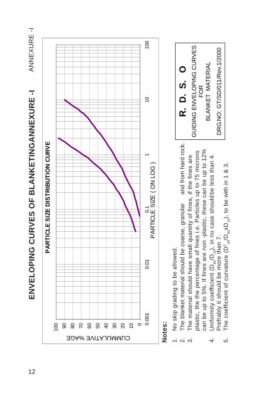
12
Not
es:
1.N
o sk
ip g
radi
ng to
be
allo
wed
.2.
The
blan
ket m
ater
ial s
houl
d be
coa
rse,
gra
nula
ran
d fro
m h
ard
rock
.3.
The
mat
eria
l sho
uld
have
sm
all q
uant
ity o
f fin
es, i
f the
fine
s ar
epl
astic
, the
the
perc
enta
ge o
f fin
es i.
e. P
artic
les
up to
75
mic
rons
can
be u
p to
5%
. If f
ines
are
non
-pl
astic
, the
se c
an b
e up
to 1
2%4.
Uni
form
ity c
oeffi
cien
t (D
60/D
10),
in n
o ca
se s
houl
dbe
less
than
4.
Pre
frab
ly it
sho
uld
be m
ore
than
7.
5.Th
e co
effic
ient
of c
urva
ture
(D
2 30/D
60xD
10),
to b
e w
ith in
1 &
3.
R.
D.
S.
OG
UID
ING
EN
VE
LOP
ING
CU
RV
ES
FOR
BLA
NK
ET
MAT
ER
IAL
DR
G.N
O: G
T/S
D/0
11/R
ev.1
/200
0
ENVE
LOPI
NG
CU
RVE
S O
F B
LAN
KET
ING
AN
NEX
UR
E -I
AN
NE
XU
RE
-I
PAR
TICL
E S
IZE
DIS
TRIB
UTIO
N C
URV
E
0102030405060708090100 0.
001
0.01
0.1
110
100
PA
RTI
CLE
SIZ
E (
ON
LO
G )
CUMMULATIVE %AGE
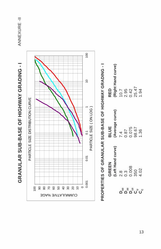
13
GR
AN
ULA
R S
UB
-BA
SE O
F H
IGH
WAY
GR
AD
ING
- I
AN
NE
XU
RE
-II
PRO
PER
TIES
OF
GR
AN
ULA
R S
UB
-BA
SE O
F H
IGH
WAY
GR
AD
ING
- I
GR
EEN
BLU
ER
ED(L
eft H
and
curv
e)(A
vera
ge c
urve
)(R
ight
Han
d cu
rve)
D60
2.8
7.4
10.7
D30
0.3
0.87
2.95
D10
0.00
80.
075
0.42
CU
350
98.6
725
.47
CC
4.02
1.36
1.94
PA
RTI
CLE
SIZ
E D
ISTR
IBU
TIO
N C
UR
VE
0102030405060708090100 0.
001
0.01
0.1
110
100
PA
RTI
CLE
SIZ
E (
ON
LO
G )
CUMMULATIVE %AGE

14
GR
AN
ULA
R S
UB
-BA
SE O
F H
IGH
WAY
GR
AD
ING
- II
AN
NE
XU
RE
-III
PRO
PER
TIES
OF
GR
AN
ULA
R S
UB
-BA
SE O
F H
IGH
WAY
GR
AD
ING
- II
GR
EEN
BLU
ER
ED(L
eft H
and
curv
e)(A
vera
ge c
urve
)(R
ight
Han
d cu
rve)
D60
0.75
3.5
10.4
5D
300.
120.
375
1.95
D10
0.01
750.
055
0.34
CU
42.8
663
.64
30.
73C
C1.
090.
731.
07
PA
RTI
CLE
SIZ
E D
ISTR
IBU
TIO
N C
UR
VE
0102030405060708090100 0.
001
0.01
0.1
110
100
PA
RTI
CLE
SIZ
E (
ON
LO
G )
CUMMULATIVE %AGE
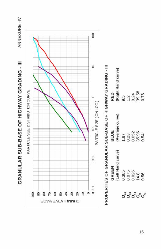
15
PRO
PER
TIES
OF
GR
AN
ULA
R S
UB
-BA
SE O
F H
IGH
WAY
GR
AD
ING
- III
GR
EEN
BLU
ER
ED(L
eft H
and
curv
e)(A
vera
ge c
urve
)(R
ight
Han
d cu
rve)
D60
0.38
51.
879.
5D
300.
075
0.23
1.2
D10
0.02
60.
052
0.24
CU
14.8
35.9
639
.58
CC
0.56
0.54
0.76
GR
AN
ULA
R S
UB
-BA
SE O
F H
IGH
WAY
GR
AD
ING
- III
AN
NE
XU
RE
-IV
PA
RTI
CLE
SIZ
E D
ISTR
IBU
TIO
N C
UR
VE
0102030405060708090100 0.
001
0.01
0.1
110
100
PA
RTI
CLE
SIZ
E (
ON
LO
G )
CUMMULATIVE %AGE

16
CR
USH
ER D
UST
& 1
0 m
m S
TON
E G
RIT
( C
OM
BIN
ED)
AN
NE
XU
RE
-V
Col
our
of c
urve
Rat
ioC
rush
er d
ust
10m
m s
tone
grit
Red
3070
Gre
en40
60P
urpl
e50
50Ye
llow
6040
Blu
e70
30
PA
RTI
CLE
SIZ
E D
ISTR
IBU
TIO
N C
UR
VE
0102030405060708090100 0.
001
0.01
0.1
110
100
PA
RTI
CLE
SIZ
E (
ON
LO
G )
CUMMULATIVE %AGE
Vinod
Placed Image
1
MECHANISED TRACK RENEWAL BY PQRS DURINGNIGHT HOURS, WITHOUT POWER BLOCK AND
BY USING CONTRACTOR’S PORTAL AT BASE INSEALDAH DIVISION OF EASTERN RAILWAY
RAJESH PRASAD*
A. K. MISHRA**
SYNOPSIS
PQRS method is a semi - mechanised method of re-laying trackand is extensively used all over in Indian Railways. Sealdah divisionbasically comprises of Suburban sections where the corridor blockshave been stipulated during night hours. More than 200 Track Km.of various sub-urban sections is overdue for renewal. Because ofsuburban traffic, blocks are being made available during night hours.In order to increase efficiency of the PQRS, we have usedContractor’s portal at base as a part of the works contract and effortswere also made for undertaking the work without power block as perstanding order of Chief Engineer and Chief Electrical Engineer ofEastern Railway. The experience of the work done has beendescribed in the paper.
1.0 INTRODUCTION
In view of heavy track structure to cater the requirement of heavyaxle loads mechanised renewal has almost become a necessity. Thisis more so when availability of block is only during night and speedyrenewal is required due to worn out track structure of Sealdah division.Due to this, mechanised track renewal by PQRS during night hourswithout power block and by using contractor’s portal at Base inSealdah Division has been adopted and in spite of many constraintslike availability of limited block period, non availability of sufficientnumber of BFRs, availing blocks only during night hours and otherdifficulties relating to operating department, maximum progress of10.10 Km. in Dec‘04 was achieved. The rationale behind usingcontractor’s portals at base will be explained later in the paper.
*Sr. Divisional Engineer(Co-Ordination), E. Rly./SDAH**AEN / RHA, E. Rly. Ranaghat.
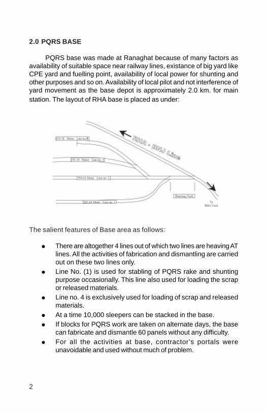
2
2.0 PQRS BASE
PQRS base was made at Ranaghat because of many factors asavailability of suitable space near railway lines, existance of big yard likeCPE yard and fuelling point, availability of local power for shunting andother purposes and so on. Availability of local pilot and not interference ofyard movement as the base depot is approximately 2.0 km. for mainstation. The layout of RHA base is placed as under:
The salient features of Base area as follows:
There are altogether 4 lines out of which two lines are heaving ATlines. All the activities of fabrication and dismantling are carriedout on these two lines only.Line No. (1) is used for stabling of PQRS rake and shuntingpurpose occasionally. This line also used for loading the scrapor released materials.Line no. 4 is exclusively used for loading of scrap and releasedmaterials.At a time 10,000 sleepers can be stacked in the base.If blocks for PQRS work are taken on alternate days, the basecan fabricate and dismantle 60 panels without any difficulty.For all the activities at base, contractor’s portals wereunavoidable and used without much of problem.

3
3.0 WHY CONTRACTOR’S PORTAL AT BASE ?
Contractor had employed his own 2 no. of portals at base. Theseportals were very sturdy and less prone to break downs. These werevery effective too.
The Portal was very innovative in design to handle higher loads withvery low fuel consumption of around 3-4 litres/hour.
3.1 Benefits of using Contractor’s Portals at Base.
As per agreement we paidto Contractor for fabrication ofone panel and loading it into BFRhaving a length of 12.60 m.(Panels used in the division were12.6 to 13.20 m long).
a. Unloading of PSC sleepers - 7.50x21 = Rs. 157.5.b. Spreading of PSC sleeper - 7.00x21 = Rs. 147.0c. Linking of PSC sleeper - 24.50x12.6 = Rs. 308.7d. Loading of panel into BFR - 20.50x12.6 = Rs. 258.3
Total Rs. 871.50 per panel
So total Cost of fabricaion, handeling and loading of one panel isRs. 871.50.If we use departmental portals, cost per panel would be morethan the double i.e. Rs. 1700/- per panel as per the following.Average cost of maintaining 2 portals per month.
= Rs. 210830 x 2 (approx)= Rs. 421660/-
Cost of 15 no. labourers required for each panel= 15 x 100 x 30.
Total cost = 421660 + 90000 = Rs. 511660/-Average no. of panels per month 342So cost per panel
= Rs. 5,11,660/342= Rs. 1496.08 per panel.
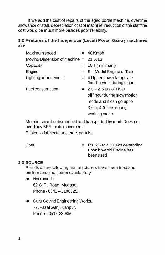
4
If we add the cost of repairs of the aged portal machine, overtimeallowance of staff, depreciation cost of machine, reduction of the staff thecost would be much more besides poor reliability.
3.2 Features of the Indigenous (Local) Portal Gantry machinesare
Members can be dismantled and transported by road. Does notneed any BFR for its movement.Easier to fabricate and erect portals.
Cost = Rs. 2.5 to 4.0 Lakh dependingupon how old Engine hasbeen used
3.3 SOURCEPortals of the following manufacturers have been tried andperformance has been satisfactory
Hydromech62 G. T . Road, Megasol.Phone - 0341 – 3100325.
Guru Govind Engineering Works.77, Fazal Ganj, Kanpur.Phone – 0512-229856
Maximum speed = 40 KmphMoving Dimension of machine = 21’ X 13’Capacity = 15 T (minimum)Engine = S – Model Engine of TataLighting arrangement = 4 higher power lamps are
fitted to work during night.Fuel consumption = 2.0 – 2.5 Lts of HSD
oil / hour during slow motionmode and it can go up to3.0 to 4.0 liters duringworking mode.
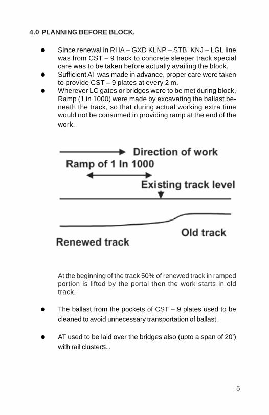
5
4.0 PLANNING BEFORE BLOCK.
Since renewal in RHA – GXD KLNP – STB, KNJ – LGL linewas from CST – 9 track to concrete sleeper track specialcare was to be taken before actually availing the block.Sufficient AT was made in advance, proper care were takento provide CST – 9 plates at every 2 m.Wherever LC gates or bridges were to be met during block,Ramp (1 in 1000) were made by excavating the ballast be-neath the track, so that during actual working extra timewould not be consumed in providing ramp at the end of thework.D
At the beginning of the track 50% of renewed track in rampedportion is lifted by the portal then the work starts in oldtrack.
The ballast from the pockets of CST – 9 plates used to becleaned to avoid unnecessary transportation of ballast.
AT used to be laid over the bridges also (upto a span of 20’)with rail clusters..

6
5.0 PQRS WORK DURING BLOCK
5.1 Since PQRS work was also done without power blocks specialprecautions were to be taken.
.5.2 Proper earthing and bending were ensured as per. Joint circulars
issued by CE & CEE. But on isolated days having rainy nights orovercast weather we thought it fit to avail power blocks.
5.3 The track had concrete sleepers interlaced in few locations. Whilelifting the existing panels. The pandrols were opened so thatconcrete sleepers are left at their position and removed from trackbefore laying new panels.
5.4 Wooden sleepers interlaced were also released in the same waybut these wooden sleepers were kept in the next tray to be carriedto the base.
5.5 Since the RHA – GXD is a double line track Mechanical hooter witha man was provided at the site. The hooter was placed at least 600m from the actual spot of work. So that an approaching of , the mancould blow the hooter and the men on work could be alerted. Apartfrom hooter one moveable whistle board with luminous paint wasalso provided on the other track in the direction of approachingtrain.
5.6 At the end of the work, site in-charge ensures track parameterswithin limit & records G & XL and certificate in the track parameterregister regarding safety of the track and block is cancelled.
5.7 Two cylinders of gas (one of DA & other of oxygen) were alwayskept ready at the site with a cutting torch to be utilized in case ofemergency.
5.8 Released rails after rail renewal next day of the block were trolleyedand kept in the converted panel tray so that they could directly bebrought to base with the released panels.

7
6.0 ADVANCE PLANNING
6.1 Existing fitting surveys were carried out with the contractor for properaccountal of released materials and avoid disputes with contractorregarding returns of released materials.
6.2 Initial L – section were taken and proposed level were also markedon each mast and other permanent structures.
6.3 LWR plans were prepared and got approved.
6.4 Sufficient quantity of ballast was ensured to be available duringPQRS work.
6.5 Deep screening is planned after PQRS manually and at certainlocation by BCM.
7.0 WORKING WITH OR WITHOUT POWER BLOCK
KNJ – LGL section is non – electrified section so power block wasnot required but in other section due to requirement of power, good amountof margin used to be wasted besides affecting the adjoining secions.
Following bonding diagram used to be followed.
8
As such PQRS work without power block became therequirement. All bonds, discharge rods, to be transported, carried,connected and disconnected by Engg. staff as per directive of TRDsupervisor/skilled staff. The details of bonding diagrams is as under:
PQRS working zone is ABCD.
Bonds 1,2,3,4,5 and 6 are to be connected before openingrail at ABCD.
Bonds 7,8,9,10 are to be connected before putting the portalon auxiliary track.
Bonds 13,14 are to be connected by Engg. staff for earthlingPQRS portal with auxiliary track before lifting the portal fromBFR and reloading on BFR.
Bonds 11 and 12 are to be connected, if the beat of PQRS ismore than 300 m.
In this connection joint guide lines of Engineering and Electrical(TRD) have been issued by CE and CEE vide letter no. W 520/2/3/12/Pt. 8 dt. 9.02.90. The instructions were having following restrictions.
Confined to day light only.To be avoided in inclement weather i.e rains, fog etc.High humidity to be avoided.Not applicable to under over line structures such as FOB, ROB,flyover, through gide.
But few traffic blocks without prior blocks were taken during nighthours also and it is confirmed that with sufficient precautions it canbe done.
8.0 POST RENEWAL WORKS
Deep screening, LWR conversion, cess repairs etc. are commonitems normally undertaken after renewal. In the division, girders of smallbridges e.g Bridge no. 115, 116, 118 etc. of RHA-GXD section havingspan of 20’ or less, were replaced by slabs manually during the shadowblocks using derricks erected at site.

9
9.0 WORKING DURING NIGHT HOURS
The corridor blocks provided in various sections planned forrenewal are
RHA – GDX section – 4 hrs. (00.00 to 4.00 hrs.).KLNP – STB section – 3 hrs. (02.15 to 05.15 hrs.).
So it was necessary to provide adequate lighting over the wholestretch where blocks are planned. 2 Diesel driven generators with oneno. of stand by are placed centrally having capacity of 5.0 to 7.5 KVAwith tubelights placed at an interval of 20 m. The provision of adequatelight used to be the part of the agreement and no extra money used tobe paid to the contractor.
The biggest disadvantage of old CST-9 track is falling of pots duringrenewal by PQRS which could endanger the safety of men working atsite. To eliminate this problem it was necessary to provide adequatefittings to the CST-9 besides providing adequate lighting arrangementsat the renewal site.
·
10
10.0 CONCLUSION
Mechanisation of track works both in field of renewal andmaintenance has become absolutely necessary and unavoidable inpresent context of Civil Engineering.
The key words in the topic of paper are night blocks, without powerblock and Contractor’s portal.
The features about night working of PQRS, trials made for renewalwithout power block and using Contractor’s Portal at base have beendeliberated in this technical paper with a hope that it would be fruitful tothe field staff of other places.
Vinod
Placed Image

1
EXPERIENCE IN USE OF RAIL GRINDING MACHINEON
NORTHERN RAILWAY
V.K.BALI*
SYNOPSIS
“Rail is the single most valuable asset. The rail/wheel interfaceis a sophisticated subject because of the huge cost involved infrequent rail renewals. Typical problems encountered on heavily loadedlines include shelling, side wear, plastic flow, low welds, corrugationand fatigue.
Rail grinding is considered the single most effective maintenancepractice to control surface conditions, restore profile and avoidpremature renewal of rails.”
1.0 INTRODUCTION
The life of rails is reduced due to fatigue, excessive side wear,development of gauge corner flaws and corrugation. Rail Profile getscontinuously changed under the passage of traffic by rail/wheelprocess, which can be reduced by rail grinding. The ground profile ofthe rail controls the location where wheels will run over the rail. Alsothe wheel guidance capability of the ground rail profile determines thelocation and extent of the interfacial contact pressure & the wheelsliding reactions on the rail.
The main reason for rail failure on the heavy density route isrolling contact fatigue i.e. development of surface and sub surfacecracks in the rail head which arise largely as a result of high points.Grinding is thought to be one of the treatments to be given to rail fortreatment of these defects and is considered essential for high wearresistance rails.
2.0 RAIL GRINDING MEANS
a) Re-shaping of the railhead to a predesigned profile to obtaina proper rail wheel contact.
b) Removal of fatigue metal from the railhead.
*Dy.C.E./TMC/Line/N.RLY
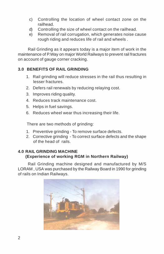
2
c) Controlling the location of wheel contact zone on therailhead.
d) Controlling the size of wheel contact on the railhead.e) Removal of rail corrugation, which generates noise cause
rough riding and reduces life of rail and wheels .
Rail Grinding as it appears today is a major item of work in themaintenance of P.Way on major World Railways to prevent rail fractureson account of gauge corner cracking.
3.0 BENEFITS OF RAIL GRINDING
1. Rail grinding will reduce stresses in the rail thus resulting inlesser fractures.
2. Defers rail renewals by reducing relaying cost.3. Improves riding quality.4. Reduces track maintenance cost.5. Helps in fuel savings.6. Reduces wheel wear thus increasing their life.
There are two methods of grinding:
1. Preventive grinding - To remove surface defects.2. Corrective grinding - To correct surface defects and the shape
of the head of rails.
4.0 RAIL GRINDING MACHINE(Experience of working RGM in Northern Railway)
Rail Grinding machine designed and manufactured by M/SLORAM , USA was purchased by the Railway Board in 1990 for grindingof rails on Indian Railways.
3
The SALIENT FEATURES OF RAIL GRINDING MACHINE SX-11 areas under :
This machine has been designed & manufactured by M/s. LORAM,USA, the details of which are as under:
1. Model : SX - 112. Number of stones : 163. Date of commissioning : 17 th May 19904. Engine : Cummins KTTA19P
700 HP Double TurboEngine
5. Speed on own Power : 60 KMPH6. Speed in Train Formation : 40 KMPH7. Grinding Speed : 1 to 6 kmph.8. Fuel consumption on own power : 60 lts./hr.9. Fuel consumption while working : 90 – 100 lts./hr.10. Water tank capacity : 800 gallons , to take
Care of Fire hazards.11. Spark guards : For arresting dust and
Sparks.12. Staff required : 7 Nos.
5.0 UTILIZATION OF RAIL GRINDING MACHINE
The machine worked on KK Line on South Eastern Railway from1990 to 1998, when it became defective on account of seizure of theEngine. The machine was recommissioned in December 2002.
Thereafter as per orders of Railway Board , the machine wasshifted to Northern Railway due to serious problem of Gauge CornerCracking in rails having been detected on Ambala-Ludhiana section .
6.0 GAUGE CORNER CRACKING ON AMBALA-LUDHIANASECTION
There had been large number of fractures and also detection ofrails having gauge corner flaws on Ambala- Ludhiana Section of Ambala

4
Division as under:
Year Total length of Total number Incidence oftrack both on of defective defective railsup and down rails detected per 100 Km.line of rails
1999-2000 194 50 25.77
2000-2001 194 89 45.87
2001-2002 194 194 100.00
2002-2003 194 229 118.00
This high incidence of development of defective rails had forcedpremature replacement /renewal of rails even when these had notcovered 50% of the life .
This was a cause of concern for the safety of traffic as such inaddition to frequent testing of rails by USFD in this section, it was feltthat grinding of rails on this section may help in reduction indevelopment of gauge corner flaws .As such the rail grinding machineavailable on S.E.Railway was decided to be shifted to this sectionand it is working since Nov. ‘2003.
Ambala- Ludhiana section
Track Structure UP Line LWR Track of 60Kg 90 UTS rails onPSC sleepers with M+7 density and 300 mmballast cushion.
DN Line LWR Track of 52 Kg. 90 UTS rails onPSC sleepers with M+7 density and 300 mmballast cushion .
7.0 PROCEDURE FOR WORKING OF RGM
1. A mini profiler (owned by RDSO) is used to measure pre grindingrail profile.
2. The angles of various grinding stones are being kept on trialerror method, as there is no scientific method of setting ofstones to give a particular rail profile.
3. After grinding to check whether the contact band has beenshifted to center or not, yellow paint is applied on rail head and

5
the width and location of contact band is recorded after passageof a train.
4. The ground profile is then measured by mini profiler & is superimposed on the pre ground profile of rail to see results achieved.
5. The post grinding profile is checked by using template also.
8.0 PROGRESS OF RAIL GRINDING ACHIEVED SINCECOMMISSIONING OF THE MACHINE
On South Eastern Railway
Length of track grinded : 195 Kms.
Length of track grinded in passes in Kms. : 2942 Kms.
On Northern Railway
Year Section Total Length Passes in Km.Block Hrs. of track
grindedin Km .
Nov.2003 UMB-LDH 186.05 43.541 285.859-Mar. 2004
Apr.2004 UMB-LDH 107.00 27.01 162.17-Nov. 2004
Total 293.08 70.62 448.06
i) The progress of the machine at present is 6 to 7 kms permonth.
ii) The availability of blocks so far has been 1.70 hrs. per day .Efforts are being made to enhance block availibity to improvethe progress of the costly machine.
iii) Presently the grinding of rails is being done on 60 Kg. rails onUP line between Rajpura-Sirhind to remove rolling contactFatigue as also to attend to rails having wheel burns . Scabbingand roaring of rails defectes to improve running .
iv) Preventing grinding of rails is being done basically to bringthe wheel/rail contact band to center of rail table . Five to ten
6
passes of grinding of rails are being given to bring the rail/wheel contact band to center of rail table.
9.0 ACHIEVEMENTS
By using the preventing grinding, the contact band on railhead is shifted to the non-gauge face side by about 20 mmi.e the contact band gets reduced from 55-60 mm to 35-45mm, which leads to:
a) Shifting of load directly to the web and thereby reducing theeccentric loads.
b) The shifting of contact band reduces tendency of flow of metalon railhead.
c) Shifting of contact band to center of rail table and reduction inits width is a favorable situation against developing gaugecorner fatigue and cracks in rail surface.
d) The progress being less the section has not been fully covered.However since USFD testing is being done every two monthswhatever defects (GCF) get generated they are detected andremoved. However since contact band is shifted to center thegeneration of these defects is definitely getting delayed .
e) Wheel burn marks are reduced thus resulting in lesserhammering action on the rails which otherwise could haveresulted in fracture. This reduction in hammering action alsoresults in lesser maintenance effort.
f) The dip in cupped welds gets reduced to some extent thusresulting in improved riding quality.
g) However it is noticed that post-grinding surface is quite roughat some locations which may be due to improper angle of thestones having been set and scratches are left on top of railtable.
10.0 MONITORING OF THE WORKING OF RAIL GRINDINGMACHINE
a) The target profile has been provided by RDSO for 52 Kg railand the target profile for 60 Kg is under process of finalization.

7
b) RDSO has prescribed a Performa for recording pre and postgrinding results and this is to be submitted to RDSO everymonth.
c) The data is analyzed by the RDSO.
11.0 COST ANALYSIS OF GRINDING OF RAILS
i) With present level of output, the cost of preventing grinding ofrails is coming out to be Rs. 78000/- per track km of railswithout CRF .
ii) Efforts are being made to enhance block availibilty for themachine to increase the progress thus in turn bringing downthe cost of grinding .
12.0 ASSISTANCE REQUIRED FROM RDSO
RDSO’s help is needed in:
a) Deciding the modules for preventive (maintenance) grindingof rails.
b) Target profile of 52 Kg and 60 Kg rails. The target profile for52 kg rail given by RDSO stipulates grinding of rail up to 2.8mm which is too much as such needs review.
c) Grinding of rails as per the target profile given by RDSO for52 Kg.rail was thought to be excessive as such only surfacegrinding of rails is being done to bring the rail wheel contactband to the center of rail head.
13.0 ANNUAL MAINTENANCE CONTRACT
i) The AMC with the representative of the OEM i.e. M/s VandanaInternational, New Delhi is in the final stages of finalization.
ii) However due to the fact that the machine is of very old modelthere is some difficulty in procurement of spares which alsoaffects the out put of the machine .
8
14.0 SOME OF THE OTHER PROBLEMS IN THE MACHINE AREAS UNDER:
i) There is no system of measuring the rail profile before grindingas well as post grinding of rails .
ii) The computer of the RGM fails frequently because of vibrations.
iii) The tempature of hydraulic oil in the machine rises above1000 C because the capacity of the hydraulic Tank is 465gallons where as the total discharge of the pumps is 800GPM. The matter has already been referred to the OEM.
iv) This rise in temp. causes bursting of hydraulic Hoses andseals quite frequently and thus stoppage of machine working.
v) Hydraulic radiator is fitted on top of the machine as such inOHE section It is difficult to clean it every day.
vi) The hydraulic transmission of working does not getdisconnected during traveling mode.
vii) The dust/iron particles get collected on the various parts ofmachine and are safety hazard for the staff operating themachine and also cause fire in the adjoining fields.
15.0 DEVELOPMENT OF RAIL GRINDERS WORLD OVER
1. Large grinders machines have been developed by variousmachines manufacturers, which have grinding stones e.g. upto 120 nos.
2. These grinders are capable of grinding switches as well .
3. The grinding speed is upto 15 kmph
4. These high capacity rail grinders have modern features likemeasurement of pre and post rail profiles, automatic settingof grinding stones to desired angles for grinding.
5. They are capable of removing corrugation and surface defectsand can restore proper profile in a single pass.
6. These rail grinders have improved spark controls and dustcollection Systems.
7. These also have foam fire suppression system.
9
16.0 CONCLUSION
1. Use of RGM on UMB-LDH section has helped in reducing thewidth of contact band and also in shifting it to the center ofrail table which will avoid eccentric loads.
2. This is also expected to help in reduction in gauge cornercracks , flow of Metal, corrugation and wheel burns
17.0 RECOMMENDATIONS
1. Rail grinding should be adopted on all high speed routes .
2. Newly developed Rail Grinding Machines with higher numberof grinding stones e.g. up to 120 available world over need tobe procured for use on Indian Railways to achieve the correcttarget profile of rails and to enhance the life of rails.
Vinod
Placed Image
1
METHODS TO INCREASE THE PRODUCTIVITY OFBALLAST CLEANING MACHINE
DEVINDAR KUMAR
SYNOPSIS
BCM machines were provided to CKP Division in the financialyear 2003-04 and subsequently continued in 2004-05. As per the jointM.O.U. signed by COM & PCE the out put of 0.1 km per gross blockhour was stipulated for ballast cleaning machine. It was targetedthat a block of 4 hrs. per day in a single spell or two blocks of 2-1/2hrs. per day will be granted to achieve the desired out put. It was inthis backdrop the machine was deployed in CKP Division. Initiallythe machine was deployed in TATA-CKP section and effective out putof 9 to 10 km were being achieved. The machine was shifted betweenTATA-JSG section in the month of October-03. It was also mentionedin the M.O.U. that length of speed restriction at the work site shouldnot exceed 2.5 km, consisting of 0.5 km for 20 kmph, 0.75 km for 50kmph & 1.25 km for 75 kmph.
With this constraint the BCM work was started and a great dealof co-ordination amongst various departments was set up. Machinestaff was motivated, field staff also put in concerted effort, whichresulted in a highest ever out put of 20.17 km in the history of IndianRailways in the month of November-03, while working in Dn. line ofJSG-ROU section. Similar performance was achieved continuouslyfor 3 months at an average out put of 19 to 20 km per month.
This has prompted me to write this technical paper for sharingmy experience with the readers regarding methods adopted, whichresulted in fantastic performance of BCM machine.
It is worthwhile to mention that with the experience gained in theyear 2003-04, excellent progress of 21.56 km have been achieved bythe same machine in May-2004 in the section of DEN(South)/CKP inbetween section RKSN-DPS.
* Sr. Divl. Engineer (West), Chakradharpur, SE Railway
2
1. INTRODUCTION
1.1 Demands on the Ballast Bed
A clean, elastic and homogeneous ballast bed is an essentialfoundation for the smooth functioning of the wheel-on-railsystem. The ballast bed has a considerable influence on theservice life and the quality of the track geometry andsubsequently the cost-eff iciency of the overall trackmaintenance.
A well-functioning ballast bed has to fulfill the following tasks:
most uniform transmission of the ballast pressure on thesubgrade,
great resistance to longitudinal and lateral displacementsof the sleepers,
easy restoration of the track geometry after its alteration(tamping and lining work),
assurance of the track elasticity to reduce the dynamicforces,
good permeability of water and air to assure a long servicelife of the sleepers and to preserve the bearing strength ofthe subgrade.
Subsequently the subgrade formation has to possess thefollowing quality features:
Adequate strength to absorb and distribute the dynamicforces.
Stability and to prevent fine particles from penetrating theballast. The sub-grade must be level and have a cross fallof 1:30 to 1:40 so that water falling on the ballast is drainedoff.
1.2 Fouling of the Ballast Bed
The desired properties of the ballast bed defined by the ballaststructure will be lost if the quantity of fine particles in the ballastbed is much greater than the permissible proportion. On newballast the permissible proportion of fine grain is normally 3 to5% of the total weight of the ballast specimen. (Normally ballast
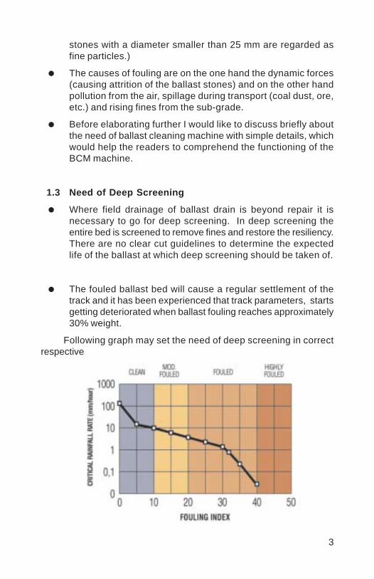
3
stones with a diameter smaller than 25 mm are regarded asfine particles.)
The causes of fouling are on the one hand the dynamic forces(causing attrition of the ballast stones) and on the other handpollution from the air, spillage during transport (coal dust, ore,etc.) and rising fines from the sub-grade.
Before elaborating further I would like to discuss briefly aboutthe need of ballast cleaning machine with simple details, whichwould help the readers to comprehend the functioning of theBCM machine.
1.3 Need of Deep Screening
Where field drainage of ballast drain is beyond repair it isnecessary to go for deep screening. In deep screening theentire bed is screened to remove fines and restore the resiliency.There are no clear cut guidelines to determine the expectedlife of the ballast at which deep screening should be taken of.
The fouled ballast bed will cause a regular settlement of thetrack and it has been experienced that track parameters, startsgetting deteriorated when ballast fouling reaches approximately30% weight.
Following graph may set the need of deep screening in correctrespective

4
It can be seen clearly that a completely fouled ballast bed doesnot prompt any drainage and there is unequal pressure distribution ascan be seen from the figure below:-
1.4 Method of Correction in Track Parameters in Older Times
In older times when track parameters were deteriorated to aconsiderable extent then a method called “Measure ShovelPacking” was adopted to correct the track parameters in whichcrushed stone chips of size varying from 10 to 20mm were insertedat rail seat. But in this method the main draw back was that itcaused a consideration reduction of the track resistance to lateraldisplacement. Hence the track was not getting stabilized aftertamping. Moreover, this method was not suitable for track wherespeed was more than 100 kmph.
In the above paragraph I have discussed briefly about the need of theballast cleaning. It is emphasized that to achieve an excellent per-formance manually ballast cleaning is not suitable. Hence mechani-cal ballast cleaning is the only solution.
2.0 REQUIREMENT OF MECHANISED BALLAST CLEANING ANDOTHER PRE-REQUISITES
To achieve a qualitative out put from the Ballast CleaningMachine, vis-à-vis the clean ballast cushion and suitable sloped subgrade, BCM should have the following features :-
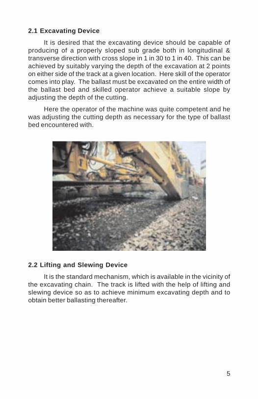
5
2.1 Excavating Device
It is desired that the excavating device should be capable ofproducing of a properly sloped sub grade both in longitudinal &transverse direction with cross slope in 1 in 30 to 1 in 40. This can beachieved by suitably varying the depth of the excavation at 2 pointson either side of the track at a given location. Here skill of the operatorcomes into play. The ballast must be excavated on the entire width ofthe ballast bed and skilled operator achieve a suitable slope byadjusting the depth of the cutting.
Here the operator of the machine was quite competent and hewas adjusting the cutting depth as necessary for the type of ballastbed encountered with.
2.2 Lifting and Slewing Device
It is the standard mechanism, which is available in the vicinity ofthe excavating chain. The track is lifted with the help of lifting andslewing device so as to achieve minimum excavating depth and toobtain better ballasting thereafter.
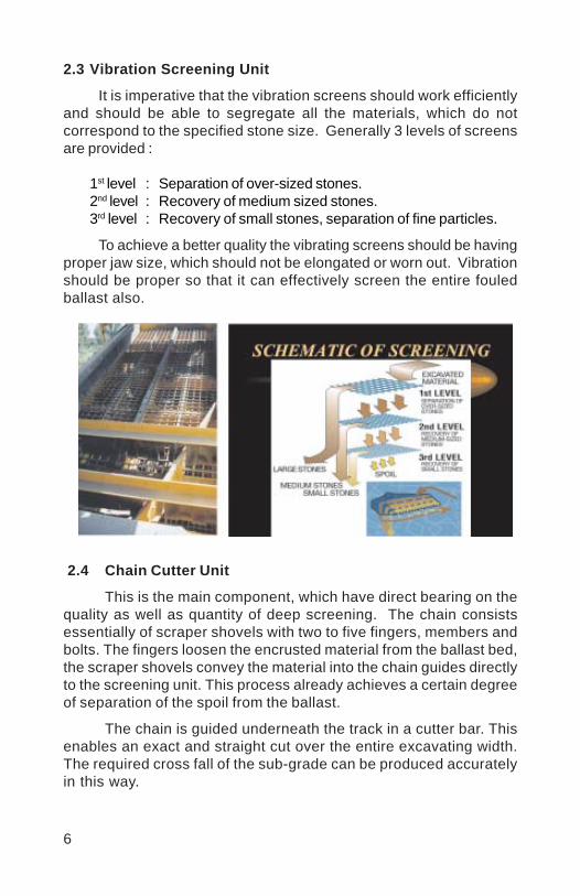
6
2.3 Vibration Screening Unit
It is imperative that the vibration screens should work efficientlyand should be able to segregate all the materials, which do notcorrespond to the specified stone size. Generally 3 levels of screensare provided :
1st level : Separation of over-sized stones.2nd level : Recovery of medium sized stones.3rd level : Recovery of small stones, separation of fine particles.
To achieve a better quality the vibrating screens should be havingproper jaw size, which should not be elongated or worn out. Vibrationshould be proper so that it can effectively screen the entire fouledballast also.
2.4 Chain Cutter Unit
This is the main component, which have direct bearing on thequality as well as quantity of deep screening. The chain consistsessentially of scraper shovels with two to five fingers, members andbolts. The fingers loosen the encrusted material from the ballast bed,the scraper shovels convey the material into the chain guides directlyto the screening unit. This process already achieves a certain degreeof separation of the spoil from the ballast.
The chain is guided underneath the track in a cutter bar. Thisenables an exact and straight cut over the entire excavating width.The required cross fall of the sub-grade can be produced accuratelyin this way.
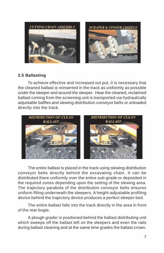
7
2.5 Ballasting
To achieve effective and increased out put, it is necessary thatthe cleaned ballast is reinserted in the track as uniformly as possibleunder the sleeper and around the sleeper. Hear the cleaned, reclaimedballast coming from the screening unit is transported via hydraulicallyadjustable baffles and slewing distribution conveyor belts or unloadeddirectly into the track.
The entire ballast is placed in the track using slewing distributionconveyor belts directly behind the excavating chain. It can bedistributed there uniformly over the entire sub-grade or deposited inthe required zones depending upon the setting of the slewing area.The trajectory parabola of the distribution conveyor belts ensuresuniform filling underneath the sleepers. A height-adjustable profilingdevice behind the trajectory device produces a perfect sleeper bed.
The entire ballast falls into the track directly in the area in frontof the rear bogie.
A plough grader is positioned behind the ballast distributing unitwhich sweeps off the ballast left on the sleepers and even the railsduring ballast cleaning and at the same time grades the ballast crown.

8
2.6 Transport of Spoil
During ballast cleaning machine heavy quantity of spoils aregenerated which is necessary to be dumped at a suitable location sothat it cannot fall on the track again. To transport the spoil a conveyorbelt is provided in the machine to transport the spoil at a suitablelocation safely at a distance of approximately 4 metres from the centerline of the track. In case of cutting, difficulty may be faced for disposalof spoil when the cutting depth is more. Here generally all the sidedrains become choked hence it is necessary that side drains arecleaned promptly to avoid re-fouling of the ballast. In cutting if suitablehoppers can also placed on the adjacent track, in case of double line,than transporting of spoils is possible at the same time, but for thisOHE block is also needed on both lines.
2.7 Efficient and Skilled Machine Staff
Efficient and skilled machine staff is a desired and very importantpre-requisite as any incremental out put is only possible when theoperator is able to adjust the condition of the machine according tothe ballast bed condition promptly.
With this brief pre-requisite of BCM and its staff, I would nowlike to elaborate various points, which were taken care of.
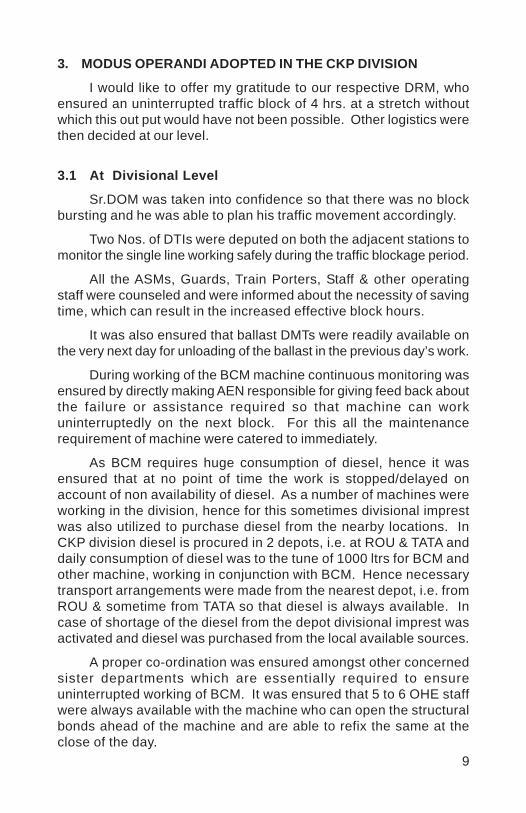
9
3. MODUS OPERANDI ADOPTED IN THE CKP DIVISION
I would like to offer my gratitude to our respective DRM, whoensured an uninterrupted traffic block of 4 hrs. at a stretch withoutwhich this out put would have not been possible. Other logistics werethen decided at our level.
3.1 At Divisional Level
Sr.DOM was taken into confidence so that there was no blockbursting and he was able to plan his traffic movement accordingly.
Two Nos. of DTIs were deputed on both the adjacent stations tomonitor the single line working safely during the traffic blockage period.
All the ASMs, Guards, Train Porters, Staff & other operatingstaff were counseled and were informed about the necessity of savingtime, which can result in the increased effective block hours.
It was also ensured that ballast DMTs were readily available onthe very next day for unloading of the ballast in the previous day’s work.
During working of the BCM machine continuous monitoring wasensured by directly making AEN responsible for giving feed back aboutthe failure or assistance required so that machine can workuninterruptedly on the next block. For this all the maintenancerequirement of machine were catered to immediately.
As BCM requires huge consumption of diesel, hence it wasensured that at no point of time the work is stopped/delayed onaccount of non availability of diesel. As a number of machines wereworking in the division, hence for this sometimes divisional imprestwas also utilized to purchase diesel from the nearby locations. InCKP division diesel is procured in 2 depots, i.e. at ROU & TATA anddaily consumption of diesel was to the tune of 1000 ltrs for BCM andother machine, working in conjunction with BCM. Hence necessarytransport arrangements were made from the nearest depot, i.e. fromROU & sometime from TATA so that diesel is always available. Incase of shortage of the diesel from the depot divisional imprest wasactivated and diesel was purchased from the local available sources.
A proper co-ordination was ensured amongst other concernedsister departments which are essentially required to ensureuninterrupted working of BCM. It was ensured that 5 to 6 OHE staffwere always available with the machine who can open the structuralbonds ahead of the machine and are able to refix the same at theclose of the day.

10
Signal Dept. was also taken into confidence and necessarysignal staff were provided with the machine to take care of any signalrequirement, specially nearer to the station where lot of junction boxand wires are there. They removed all the infringements well in advanceand the same was refixed at the time of closing of the work so thatminimum interruption to the traffic is caused.
4 machines were deployed simultaneously including BCMmachine so as to achieve increased out put. These machines were –(1) BCM, (2) BRM, (3) Duomatic & (4) DGS. These machines weremarshelled together and were sent in the same block section at atime, which also resulted in simultaneous operations of ballastregulation, packing and consolidation. The BRM machine was ableto regulate the ballast behind the BCM machine, for the same day’sas well as previous day’s work. Here Duomatic 8055 was very efficientand it was possible to tamp the same days work and previous dayswork also. It became possible to open the traffic at 30 kmph insteadof 20kmph on the same day after closing of the work, whichsubstantially reduced the time loss.
3.2 At Field Level
3.2.1 Item taken care of before Block
All the rail posts like TPTC, SEJ, LWR and other boards wereremoved well in advance as this could have infringed the workingportion of the BCM. It is worthwhile to point out that during working ina particular block section we encountered the rail posts, which wereburied at the center of the track. These rail posts were probably laidfor initial laying of the track. When these were encountered duringone of the block, the entire length of the track, where BCM wasdeployed, was surveyed and it was seen that in various block sectionsthese rail posts were at a considerable height and could have infringedthe cutter chain. Hence these were cut by gas well in advance.
All L.C. gates & their check rails were opened in advance.
All the deficient & defective fittings like pendrol clips, liners andother fittings were recouped as any deficiency or defective fittingsmight cause dropping of the sleeper at the time of lifting of the trackduring working. Once the concrete sleeper gets dropped, aconsiderable time of approx. 10 to 15 minute is lost, which results inloss of out put.
11
In JSG-ROU section most of the platforms are rail level. Hencethere are two options either to leave the platform area or to open therail level platform so that work can be carried out in yards also. Henceall the PCC blocks of rail level platform were removed and yard’s mainlines were also deep screened.
Crib and shoulder ballast of one sleeper in advance was openedbefore taking of the block as a considerable time is lost while placingthe chain and cutter at the start of the work. Due to this we achieveda saving of at least 10 min. and cutter was placed in advance and itwas fixed promptly with the chain at the time of block. In case ofcurves, super-elevation was written on every 5th sleeper so that operatorof the BCM can easily see and adjust the working accordingly.
A survey of critical implantation was also carried out and all theOHE implantation was listed and location where the chances ofinfringement was there, were identified so that special precautionscan be taken at those locations.
All the bridge approaches were also opened well in advance.Here it is worthwhile to point out that generally bridges are there inevery block section hence considerable time is lost while starting thework on other side of the bridge on the next day. Here a 2nd cutter barwas arranged and it was placed by opening shoulder and crib ballastbefore closing of the previous day’s work. This also resulted inconsiderable time saving on the next day’s block.
As the effective out put entirely depends upon the skill of theoperator and other staff hence every effort was made to make themachine staff comfortable and motivated.
It was ensured that routine maintenance of the machine wascarried out well in time before taking up of the block so that machinework continued uninterruptedly.
Traction Dept. also deployed 5 to 6 staff so as to open thestructural bonds well in advance and this was refixed before closingof the block.
Signal Dept. also deployed their necessary staff so as to takecare of the interruption to signal installations like - junction boxes,axle counters etc.
One PWM each was also stationed with walkie-talkie on boththe adjacent stations. They co-ordinated with the staff of Operatingand other Departments so that machines are properly marshelled andready before granting block. They also ensured that points are properly
12
set so that minimum time is wasted for despatching of the machineafter granting block. Similarly they also ensured that points are againreset to receive the machine at the closing of the work and time lossis avoided. We experienced that at least 20 to 30 min. were saved bythis co-ordination amongst the staff, which resulted in more effectiveblock.
3.2.2 During block operation, following items were takencare of
PWI ensured that 60 to 70 competent personnel are availablewith BCM and other machine to take care of various items during theblock work. This labour forces along with supervisors ensured thatworking portion of the track is cleared from all the infringements, allthe missing fittings were getting recouped, all the track parameterswere safe after working of the BCM machine. It is to point out thatthis labour force was highly essential as sometimes very small andsilly mistakes are committed and assistance is required immediately.So the assistance was provided promptly, which resulted in saving ofthe time loss.
Although ballast regulator distributes ballast evenly after screeningstill ballast has to be drawn manually below rail seat so as to keeptrack properly aligned and leveled. Sufficient man power was providedjust behind BCM, which continued the ballast insertion during theoperation of the BCM so that ballast may not remain scanty.
Similarly sufficient man power was kept along with Duomaticmachine to draw out the ballast from the adjacent lines so thatDuomatic can tamp the work of the same day. Here it is worthwhile tomention that after initial tamping track was opened with a speed of 30kmph instead of 20 kmph, which resulted in considerable saving oftime loss.
Sufficient man power was kept for various miscellaneous workslike squaring of sleeper, recoupment of fittings, renewal & fixing ofcheck rail of L.C., making up of surface of L.C. so that the minimumback work is left at the time of closing of the work, as all these items,if lagging far behind, will affect the out put & safety.
A gang was also formed to pick up the slack manually for thelast stretch of deep screening, which is approximately 40metres asDuomatic was not able to tamp the last stretch of the track.
Similarly all pre-tamping and post tamping readings were takenand rectification was done within the block day.

13
As pointed out earlier great deal of effort was made by the Divisionto ensure that regular ballast DMT, sufficient to cater to one day work,is made available before the start of the next day’s work. For this theactivities were expedited at the ballast depot which was at a distanceof approx. 50 kmph from the work site. It was ensured that the emptyrake is placed on same day. It is loaded within the minimum possibletime and loaded rake is taken out from the depot and is available atthe adjacent station before morning of the next day. Before takingBCM block this ballast rake was moved by taking a block of 1 & 1-1/2 hrs. so that it could unload the ballast on the previous day’s work.
3.2.3 Post Work
As pointed out in the previous paras PWI ensured that theminimum back work is left behind and all the post machine work iscarried out on the same day itself. It was ensured that guard rail ofbridges, check rail of L.C., resetting of PCC blocks of L.C. were fixedon the same day after BCM work.
All the structural bonds, wires, junction box etc. were also fixedon the same day to provide minimum interruption to the traffic.
As pointed out a qualitative tamping work was taken from theDuomatic and it was possible to open the track at 30 kmph, whichhas also resulted in less time loss.
It is very important to point out that in a gross block of 4 hrs.generally net effective block of 2 hrs. 50 min. is available as 1 hrs. 10min. is generally wasted in pre & post machine movements. But bytaking of the precautions and with better co-ordination we were ableto achieve a net effective block of 3 hrs. 15 min. on an average.Interruption to the working were also kept to the minimum possible.
Generally the maximum out put of the BCM machine was 400cum per hour, means approx. a progress of 200 to 300 metres of deepscreening per hour. If all these precautions and co-ordinating effortswere not taken then an average out put of 400 to 600 metres was onlypossible in a 4 hrs. block period. But we were able to achieve amaximum out put of 300 to 350 metres per effective block hour and onan average a daily out put of 800 metres. per day was achieved. Thusin a month of 30 days, if the work is done daily, an out put of 24 kmcan be achieved. However, one day’s rest in a week is generallyrequired to rejuvenate the staff. Hence 4 to 5 days were kept off in amonth and a maximum out put of 20.17 Km. was achieved in themonth of November 03.
14
Same performance was maintained and a progress of 19 kmapprox. in next two months was achieved.
With the experience gained from the machine in the year 2003,CKP Division ensured the highest ever progress of 21.56 km. in themonth of May-2004 in the section of DEN(South)/CKP.
4. CONCLUSION
4 hrs. block at a stretch is highly essential to increase theeffective out put.
Great deal of co-ordination is required amongst officers atDivisional level and ground level staff in the field level.
Various logistics required for the machine should be keptprepared in advance to achieve minimum interruption of theblock and to save time loss during the block.
Post BCM work is also very essential and sufficient contractsshould be available in hand to handle post BCM work like -cleaning of haunch ballast & cleaning of the muck & cess.
At the end it is emphasized that nothing is impossible for thehuman, only strong will and hard work is required.
Vinod
Placed Image
1
RENEWAL OF DIAMOND CROSSING LAYOUT BYT-28 MACHINE - A FIELD EXPERIENCE
SITESH KR. SINGH1
SYNOPSIS
Renewal of Diamond Crossing wooden layouts in Burdwan stationyard of Howrah Division, Eastern Railway by Fan shaped layoutsmanually was a daunting task for the Engineers. There is large numberof signal rods as well as running track on either side of these diamondcrossings. To execute the work within corridor block of 3 – 4 hourswas not feasible manually. Hence, the work was planned by the useof T-28 machine with innovative technique. The article describes thescheme of actual execution of the work using T-28 machine.
1.0 INTRODUCTION
Burdwan is an important junction station at Km 106/21-23 onHowrah – Asansol quadruple G. C. route via Chord line as well asMain line section of Eastern Railway under Howrah Division. Thisstation yard has 14 sets of Diamond crossings on passenger runninglines. These points were laid on wooden layout with 90R rails of 1962.These were required to be renewed with Fan shaped layouts sleeperswith 60 kg rails. It was not possible to execute this work manuallywithin 3-4 hours of corridor traffic block due to large number of signalrods as well heavy busy traffic on all lines of this quadruple suburbansection. There is space constraint to keep long fan shaped sleepersin between tracks. Considering the limitation there was no option butto execute the work by T-28 machine. As the work was being done forthe first time using T-28 machine, the main job was to do necessaryadjustments in lifting arrangement of T-28 machine, proper balance ofweight, minimum infringement to adjacent tracks during crawlermovement and within minimum traffic block.
2.0 LIMITATION OF OPTIONS
It was not possible to use conventional method of renewal ofsleepers manually. Due to large number of rod operated points &crossings, adequate space was not available for stacking of Fan shapedsleepers near Diamond crossings. Burdwan station yard being on heavy
* Sr DEN/II/ HWH
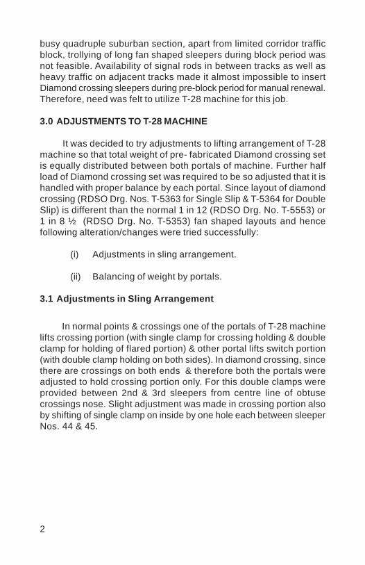
2
busy quadruple suburban section, apart from limited corridor trafficblock, trollying of long fan shaped sleepers during block period wasnot feasible. Availability of signal rods in between tracks as well asheavy traffic on adjacent tracks made it almost impossible to insertDiamond crossing sleepers during pre-block period for manual renewal.Therefore, need was felt to utilize T-28 machine for this job.
3.0 ADJUSTMENTS TO T-28 MACHINE
It was decided to try adjustments to lifting arrangement of T-28machine so that total weight of pre- fabricated Diamond crossing setis equally distributed between both portals of machine. Further halfload of Diamond crossing set was required to be so adjusted that it ishandled with proper balance by each portal. Since layout of diamondcrossing (RDSO Drg. Nos. T-5363 for Single Slip & T-5364 for DoubleSlip) is different than the normal 1 in 12 (RDSO Drg. No. T-5553) or1 in 8 ½ (RDSO Drg. No. T-5353) fan shaped layouts and hencefollowing alteration/changes were tried successfully:
(i) Adjustments in sling arrangement.
(ii) Balancing of weight by portals.
3.1 Adjustments in Sling Arrangement
In normal points & crossings one of the portals of T-28 machinelifts crossing portion (with single clamp for crossing holding & doubleclamp for holding of flared portion) & other portal lifts switch portion(with double clamp holding on both sides). In diamond crossing, sincethere are crossings on both ends & therefore both the portals wereadjusted to hold crossing portion only. For this double clamps wereprovided between 2nd & 3rd sleepers from centre line of obtusecrossings nose. Slight adjustment was made in crossing portion alsoby shifting of single clamp on inside by one hole each between sleeperNos. 44 & 45.
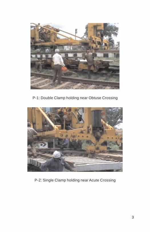
3
P-1: Double Clamp holding near Obtuse Crossing
P-2: Single Clamp holding near Acute Crossing
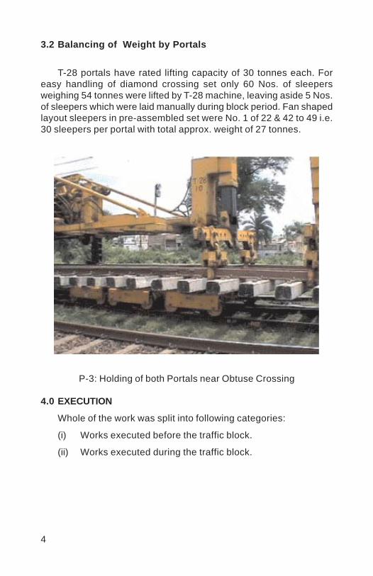
4
3.2 Balancing of Weight by Portals
T-28 portals have rated lifting capacity of 30 tonnes each. Foreasy handling of diamond crossing set only 60 Nos. of sleepersweighing 54 tonnes were lifted by T-28 machine, leaving aside 5 Nos.of sleepers which were laid manually during block period. Fan shapedlayout sleepers in pre-assembled set were No. 1 of 22 & 42 to 49 i.e.30 sleepers per portal with total approx. weight of 27 tonnes.
P-3: Holding of both Portals near Obtuse Crossing
4.0 EXECUTION
Whole of the work was split into following categories:
(i) Works executed before the traffic block.
(ii) Works executed during the traffic block.

5
4.1 Works Executed before the Traffic Block
(i) Assembly of new turnout
New turnout was assembled with complete fittings. Suitablelocations were chosen in the yard so that there was minimuminfringement of OHE mast or signal post for trollying of fabricated setto site of work.
(ii) Signaling work
All pre-block work of signaling was completed in assembled turnout.
P-4: View of completed Signaling works
(iii) Sleeper Nos. 50 to 54
These end sleepers were trollied in advance to suitable locationsas near to Diamond crossing to be renewed as possible.
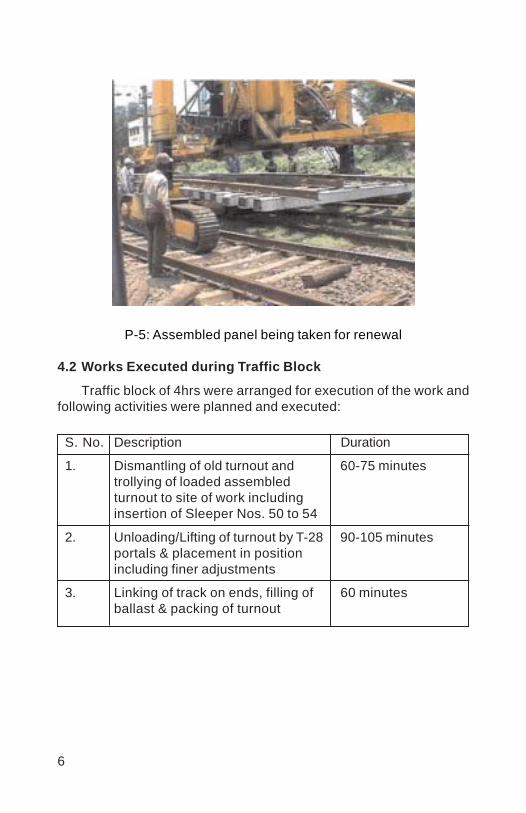
6
P-5: Assembled panel being taken for renewal
4.2 Works Executed during Traffic Block
Traffic block of 4hrs were arranged for execution of the work andfollowing activities were planned and executed:
S. No. Description Duration
1. Dismantling of old turnout and 60-75 minutestrollying of loaded assembledturnout to site of work includinginsertion of Sleeper Nos. 50 to 54
2. Unloading/Lifting of turnout by T-28 90-105 minutesportals & placement in positionincluding finer adjustments
3. Linking of track on ends, filling of 60 minutesballast & packing of turnout

7
P-5: Linking of track in progress
5.0 PROBLEMS FACED & SOLUTION
Following problems were encountered during execution of thiswork:
At many locations lock bars were housed between runningrail & check rails opposite acute crossing nose. This problemwas overcome by providing ‘U’ Clips in place of check blocksto allow passage of lock bars.
Rods run obstructed free movement of portal crawlers.Sufficient wooden blocks were provided to safeguard signalrods.
Infringement of long Diamond crossing sleepers with concretesleepers of adjacent tracks. Taking accurate measurementsin advance to foresee necessary adjustments/shiftingminimized this problem.

8
P-6: Sleeper Nos. 50 to 54 inserted manually
Movement of loaded motorized trollies over enroute Diamondcrossings. Adequate precautions need to be taken whilenegotiating such locations.
Corridor blocks were available mostly during nighttime &hence adequate lighting arrangement required particularlynear portal wheels. Each portal was provided with independentgenerators for proper lighting below portal under frame.
Intermittent failure in working of T-28 portal or its motorizedtrolley. Ensuring fitness of machines, provision of gas cuttersand adequate manpower is essential.

9
P-7: Train passing over renewed Diamond Crossing
6.0 RECOMMENDATION
In view of the successful execution of Diamond crossing renewalby T-28 machine, it is recommended to utilize T-28 machine moreconveniently for this work. The above adjustments facilitate better loadbalance by portals, speedier renewal, less chance of traffic block burst,cheaper in cost and better quality work.
Vinod
Placed Image

1
DESIGN LINING ON BUSY ROUTES
ASHISH AGRAWAL *ROOPESH GADEKAR **
SYNOPSIS
Good riding depends mostly upon the alignment of the track.TRC has given very heavy weightage to alignment than otherparameters of the track. Generally the alignment between two goodpoint is not perfect. Sometimes this is distinctly visible on the trackor there are slight error in the alignment, not apparently visible on thetrack. In recent past many methods have been developed to measurethe slew required on the track. We are interested in working with themethod that can be used on busy routes (Automatic Block Section).For this purpose we have used the tools developed by Mr. S. K. Gupta,Mr. Malkhan Singh and Mr. R. Solanki described in their paper“Innovative Equipments & Tools for Track Maintenance.” This methoddoes not require traffic blocks for measuring the slews required forthe track. This paper explains how to achieve the design lining onbusy routes by using the track machine effectively in day as well asnight.
1.0 INTRODUCTION
The perfect alignment in the field can be achieved with the helpof design lining. The design lining requires the measurement of slewbetween two good points. There are different methods developed inthe past to measure the slew required for perfect alignment on thefield.
The method described in IRTMM uses 40metre chord for takingslew measurement. In our opinion this does not give the correct pictureof al ignment of the f ield. The second method used byShri S. K. Pathak, SR. DEN (Co.) Nagpur, H. S. Chaturvedi,ADEN Warora, B. K. Jha, ADEN, Betul, Atul Deshpande, JE.(W)Nagpur, of Nagpur Division of Central Railway. They have used rangingrods & theodolite for the measurement of slew. This method requiresthe availability of traffic block as the setting of theodolite can not bedisturbed during measurement of slews. The other method used by
* Ashish Agrawal, ADEN DRD, Western Railway** Roopesh Gadekar, JE(P-Way) PLG, Western Railway
2
Mohd. Shamim, AEN/Surat & G. P. Sisodia, SSE (PW) NVS describein the paper Viseur-Mire Aided Design Alignment of Track. Thelimitation of this method is viseur has small range of visibility.
We have used the tools & equipment developed byShri. S. K. Gupta, Shri. Malkhan Singh and Shri. R. Solanki of Kotadivision. This method does not require traffic blocks and can be usedon busy routes. The following equipments are used in this method.
1) Theodolite.2) Scale Sliding Table (SST) : This is a table fixed on which
theodolite slides laterally at any required distance fromreference.
3) Satellite : is a teethed graduated scale to read the value ofslews.
4) Target : is set at other good point and has got a red verticalcentral line passing to zero point (chord point) towardstheodolite.
5) VHF Set : 3 Nos.
We have developed tools & equipment based on the paper writtenby them for the measurement of slews on field.
2.0 SURVEY OF THE TRACK:
This method requires four persons with PWI. The advantage ofthis method is that it can be worked on track without taking trafficblock.
The step by step procedure of this method is as follows :
i) Identification of two Good points (correct alignment) : This ismost important point of the survey. Whole survey dependsupon identification of good points. The thedolite available withus is of the range of 400 – 500 mtrs. Good points available onthe track are L.C., Bridges, Tangent Points of curves, P&Cetc. If two good points are available within the range of thedolitethen the survey becomes easier, but if not then problem arises.Solution of this problem depends upon the experience andcorrectness of PWI conducting the survey as he has to choosegood points with the available data and track structure visible.The survey fails if PWI takes good point on incorrect alignments.
3
After finding the good point,SSt is fixed at one good point andtarget on the other good point. Coincide the target with the verticalhair line of thedolite.
The satellite is designed in such a way that if we place the satellitein between SST & target, it gives us the designed slew along withdirection required at that location of the track with reference to SST &target (good points). As per opinion of sectional PWI, he may takethe readings of satellite on every 30th or 20th sleeper and finally distributeon alternate sleepers, showing the direction of slew. This is to notethat taking reading and writing it on the sleeper may be done at thesame time to avoid repetition of work. The daily progress ofmeasurement of slew on the field is 2km.
3.0 WORKING OF TAMPING MACHINE:
The slews are available at alternate sleepers on the field. It isimportant to note, at this stage that the sectional PWI should himselfaccompany in front cabin of the machine. If two VHF sets are availablethen that will be helpful. Generally one can easily see the value ofslew written on the sleeper with white paint while feeding the datafrom the front cabin. It simply requires seeing the data & feeding itinto the front cabin. Moreover this is to mention here that we couldeasily see the slew written on the sleeper at night also. Personstanding in front of the machine can also read the value of slew writtenon the sleeper & with the help of VHF set he can communicate withthe PWI sitting in front cabin.
Our sectional PWIs have used the innovative method for feedingthe slews sitting in the front cabin without seeing every time on thesleeper. They have made the paper rolls in which they have writtenthe slews required on every alternate sleeper. From the front cabinthey start working at one point where they check the reading on thepaper rolls with the value written on the sleeper at field. If these twovalues match then they start feeding the values of slews in the frontcabin. They check the value of slew written on the paper roll with thevalue of slew on the sleeper on every 20th sleeper. This system reducesthe field work as it doesn’t require writing the slew on every alternatesleeper. Moreover in the night this is very useful as it causes veryless strain on the person sitting in front cabin. However the PWI hasto check the reading on every 20th sleeper with the field data. Weworked both during day as well as in night successfully.

4
4.0 FIELD & GRAPHICAL ANALYSIS
4.1 At Boisar station the distance between track and platform copinghas increased to the value of 1910mm causing serious trouble tothe passengers. With the help of design lining the track has beenslewed to the correct alignment (1680mm), resulting into thepermissible distance between track and platform coping. Thisrequired slewing of track by more than 200mm. To achieve slew of200mm, inner shoulder ballast was cleared and the help of OHEstaff taken simultaneously.
4.2 Track between 83 Km. To 101 km. Tamped in design modeachieving slew upto 150mm.
4.3 Normally the slew upto 20 to 40 mm can be easily obtained in thefield with the help of machine. However if the slew required ismore than 50mm then the portion of shoulder ballast should becleared to accommodate required slew. As per IRTMM, heavyslewing normally is to be done in steps of not more than 50 mm.That has been followed while doing our machine tamping.
Graphical representation of value of TGI from Dec. 03 toSept. 04 have been Plotted & following conclusions have beenmade:
1) The machine tamping in smoothening mode has been donein Jan & Feb 04 from km. 92 to 102 along with lifting. Theimprovement in TGI in March 2004 in Comparison to Dec.2003 was 7.54 for up line. However after design tamping inJuly & Aug. 2004 the improvement in TGI in Sept. 2004 was23.3. This shows that improvement in value of TGI after designtamping is 3 times better than in smoothening mode.
2) The value of TGI from km 92 to 102 drops down to value of71.9 in June 2004 from value 78.63 in March 2004. This showsthat retaintivity of tamping is very less in smoothening mode.Moreover there is very less improvement of alignment of trackin smoothening mode. Hence value of TGI do not retain forlong time in smoothening mode.
3) The value of TGI in Sept. 2004 for km 92 to 102 is after 1½month design tamping. This shows that once we do tampingin design mode then retaintivity of TGI is much more asalignment of the track has improved to the designed values.
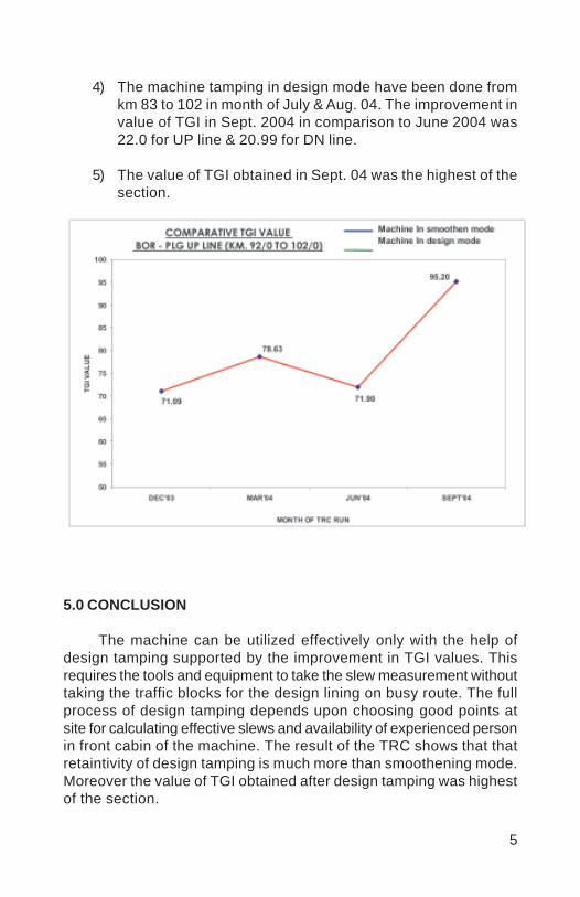
5
4) The machine tamping in design mode have been done fromkm 83 to 102 in month of July & Aug. 04. The improvement invalue of TGI in Sept. 2004 in comparison to June 2004 was22.0 for UP line & 20.99 for DN line.
5) The value of TGI obtained in Sept. 04 was the highest of thesection.
5.0 CONCLUSION
The machine can be utilized effectively only with the help ofdesign tamping supported by the improvement in TGI values. Thisrequires the tools and equipment to take the slew measurement withouttaking the traffic blocks for the design lining on busy route. The fullprocess of design tamping depends upon choosing good points atsite for calculating effective slews and availability of experienced personin front cabin of the machine. The result of the TRC shows that thatretaintivity of design tamping is much more than smoothening mode.Moreover the value of TGI obtained after design tamping was highestof the section.

6
Reference:
1. Indian Railway Permanent Way Manual 19862. Indian railway Track Machine Manual 20003. “Viseur – Mire Aided Design Alignment of Track” by Mohd.
Shamim, AEN/SURAT, G. P. Sisodia, SSE(P-way)/NVS,Western Railway.
4 “Notable Improvements In Track Geometry Parameters OnNagpur Division Of Central Railway ,” October 2002,Publishedby IPWE.
5. “Innonative Equipments and Tools For Track Maintenance”2000,Published by Indian Railway Institute Of CivilEngineering, Pune.
Vinod
Placed Image

1
T-28 : RENEWAL OF TURNOUTS, RECTIFICATION/SHIFTING OF CROSSOVERS (A CASE STUDY) AND
SUGGESTIONS
SUNIL GUPTA*
SYNOPSIS
This paper shows steps involved in mechanized renewal ofturnouts using T-28 machine along with its advantages & limitations.Also, the highly advantageous use of T-28 in correction and shiftingof crossovers is discussed with a case study of Nekurseni yard ofKharagpur Division. Suggestions are given for further mechanization& improvement.
Key words
T-28, PSC, fanshaped, block, turnout, crossover, jib crane, portal,assembly, cess, SR, SRJ, TNC, ANC, HOC.
1.0 INTRODUCTION
Before proliferation of PSC sleepers as a high performance substituteof CST-9, IRS, STO & Wooden sleepers, most of the track renewal andmaintenance work in Indian Railways used to be labour intensive. Buteven Indian Railways had to go for mechanization of track renewal &maintenance to overcome the only draw back with PSC sleeper i.e. itsheavy weight. Also, mechanization was attractive because PSC sleepershave much better amenability to machine working due to its uniform andregular geometrical shape.
With the development PSC sleepers for turnouts came the need forhandling PSC turnouts with machine.
2.0 MANUAL RENEWAL OF PSC TURNOUTS
Renewal of turnouts with PSC sleepers is also done manually. Theproblems encountered in manual renewal are as follows:
Difficulty in handling heavy turnout sleepers weighing upto550 kg.Long duration of work due to slow progress of work in a phased
* Sr. DEN/Co-ord/Ranchi S.E. Rly.
2
manner like manual TSR.Disruption to the traffic for a longer period by way of speedrestriction.Difficulty is ensuring good quality of layout regarding sleeperspacing, welding, etc as the work is done in-situ.Safety at work site is required to be ensured for a longer durationas all work is done in situ.
Most of these shortcomings are overcome in mechanised renewalof turnouts using T-28 machine.
3.0 MECHANISED RENEWAL OF TURNOUTS USING T-28MACHINE
The stages involved in mecahnised renewal of turnouts can bebroadly put in following five groups:
(i) Advance planning.(ii) Assembly preparation.(iii) Pre block preparation.(iv) Block working for renewal.(v) Post renewal activities.
3.1 Advance Planning
The following aspects need to be taken care of:
MOU with Operating department for availing traffic blocks.Identification/Preparation of location on cess where the layoutcan be assembled. The location should be such that thereshould be no infringement to T-28 portals when it moves withthe new assembly. Obstructions due to masts and S&T gears,rods etc should be minimum & a plan should be chalked out tonegotiate the unavoidable obstructions.Availability of full compliment of material including requirednumber of glued joints.Survey and Measurement of geometry of existing layout.Calculations to check for any discrepancy in existing layoutwhich may need to be rectified during renewal.In case shifting of SRJ/ANC is necessary a joint survey shouldbe conducted with S&T and TRD departments to ensure

3
simultaneous preparation and corrective action by them.3.2 Assembly Preparation
The activities involved are:
Spreading of sleepers on a stage sequentially as per cumulativespacing from SRJ.Checking of mid and quarter point ordinates of curved stockrail and tongue rail and rectification where required.Fixing of all bearing plates of switch portion, fixing of switch,lead rails of appropriate length, crossing, check rails, etc.Welding.Checking of throw & setting of switch for both normal & reversemovement.
Precautions
Grooved rubber pads should be pasted to the sleepers withglue.All the four joints ahead & behind crossing should be gapless.Correct length of lead rails should be ensured.Proper driving of ERCs with liners in position should be ensuredto avoid falling of sleeper due to twist in the assembly duringlifting & movement by portals.
3.3 Pre-Block Preparations
3.3.1 Site preparation
Deepscreening of turnout including approach track, if due, shouldbe so planned that it is completed one day in advance of plannedblock for renewal.Reference points like proposed SRJ, ANC, etc. should bemarked at site.If required, approach track should be lifted with provision ofproper ramp so that it can be matched with the level of theturnout after renewal with minimum effort.Crib ballast should be opened up and 20 kmph imposed, only
4
one day in advance.Based on proposed location of SRJ, including rectificationinvolved if any, cutting of rails should be completed one day inadvance.In case shifting of SRJ is involved, a new foundation may berequired for rodding arrangement for point operation, in case ofmechanised interlocking. This should be completed in advancein consultation with S&T branch.One gas cutting equipment with sufficient gas in cylinder shouldbe arranged to clear obstructions, if any encountered, duringdismantling or preparation of bed.In case track centre is less than 5.0 m, there is a possibility ofsleeper No.81, 82, 83/52, 53, 54 of the new assemblyoverlapping with the existing sleepers on adjacent track. Actualsite measurements should be taken in advance and sleepersof the adjacent track may be re-spaced, if required.
3.3.2 Machine preparation
The machine should be in good working condition. All itsmovements should be checked for proper functioning.Adequacy of fuel, hydraulic oil & track machine staff should beensured.Adequate number of wooden blocks should be available tofacilitate negotiating of crawlers over S&T and electrical gearswithout damaging them.Before block is imposed, the portals should be ready over thenew assembly with clamps in position to lift it and move.(fig-1)
3.3.3 Other preparation
Block programme should be finalized in consultation with S&Tbranch and confirmed at least 24 hrs in advance to ensureavailability of S&T staff at site for block work.TRD department should also be informed if there is major shiftingof ATS/ANC.A caution order should be imposed on the adjacent line fordriver of passing trains to OES & BLW.

5
3.4 Block Working for Renewal
Jumpers should be provided as per site conditions beforecausing a discontinuity in track with electric traction.As soon as traffic block is imposed, track should be protectedas per extant provisions.The existing turnout is dismantled.The ballast bed is leveled properly to accommodate extrathickness of PSC sleepers.Shifting of the new turnout assembly with portals can startsimultaneously and reach as near as possible to the positionin which it is to be laid. So that only longitudinal movement isbalance. As latest movement is more tedious & time consuming.After preparation of bed, the new turnout assembly is laid inposition and continuity of track effected by fish plating thejoints.(fig-2)Visible kinks, if any, are eliminated with one portal using thealigning hook attachments. The other portal meanwhile clearsthe site.(fig-3)Ballast is put back and one round of packing done to maketrack fit for traffic.After checking gauge & XL and ensuring that there is noinfringement block can be cancelled.
3.5 Post Renewal Activities
All measurements of the turnout to be checked & rectified ifdisturbed during laying.SRJ to be welded at the earliest with insertion of GJ whererequired.Availability of all fittings to checked and ensured once again.Ballasting & three rounds of packing.Segregating & stacking released Pway material.

6
4.0 ADVANTAGES OF MECHANISED WORKING
Almost all the drawbacks associated with manual renewal ofturnouts are overcome in mechanised working using T-28. Theadvantages are as follows:
The heavy PSC turnout sleepers can be handled using Jib Cranefor preparation of assembly. Difficulty, if any, in manual handlingduring assembly of the layout does not affect traffic as thework is not done in situ.Duration of in situ working is reduced substantially from about50 hrs to only 3 hours.Disruption to traffic, by way of SR, is minimized from about 14days to 9 days.Convenience of cess working can give very good quality ofrenewal in terms of sleeper spacing, layout geometry and betterquality of welding.Duration for ensuring safety at work site reduces from 50 hrs to3 hrs.Mismatches or shortage in material, if any encountered, canbe sorted out in advance during preparation of assembly oncess.S&T working for changing/fixing FPL etc is much moreconvenient and peaceful as it can be done in advance on cess.
4.1 Limitations of Mechanized working
Problems encountered in T-28 working are as follows:
Sufficient and appropriate space is not available at all sites forthe new turnout assembly. In such cases, the assembly hasto be done in some over run line, sand hump, etc thus affectingoperations.In yards with mechanical interlocking, it is quite cumbersomefor the portals to negotiate over the S&T rodding arrangement.In spite of all precautions, if some S&T gears are damaged,operations may get affected.In case of breakdown of machine, which is not rare, therepercussion on punctuality may be severe. Because, afterhaving dismantled the old turnout it is not possible to put thenew turnout in position manually during the planned block period.
7
5.0 UTILISATION OF T-28 FOR RECTIFICATION/SHIFTING OFCROSSOVERS
Situations do arise where the crossover length needs to becorrected by shifting one or both the turnouts, for improving thealignment.Also there are cases where the CSL of a line is to be increasedby shifting a turnout or a complete cross-over.
In such cases T-28 can be used very advantageously.
5.1 Case study:-Crossover Rectification in NSI yard
5.1.1 Problem
There was a severe kink in the south end crossover in NSIyarand manual rectification was quite difficult since both pointshad already been renewed with PSC fanshaped layouts.
5.1.2 Brief particulars
The south end crossover of NSI yard between UP & DN mainline, comprised of Pt.No.S5S and S5N, both 1 in 12 with PSCfanshaped layout.Point No.S5S is on straight track on UP line while Pt.No.S5Non a ½° curve on DN line.As can be seen in fig.4, the track centre to centre distancebetween UP and DN line varies from 5.02 m at ATS of Pt.No.S5Sto 7.12 m at ATS of Pt.No.S5N.
5.1.3 Crossover calculations:
From measurement of track centre to centre distanceat every 1 m, the average track centre was determinedas 5.95 m.Theoretical TNC to TNC= D Cot α α α α α − G Cot ααααα/2
= 5.955 x 12-1.673 Cot ααααα /2= 31.31 m
Theoretical ANC to ANC= (TNC to TNC) - 2x0.186= 30.93 m
Actual ANC to ANC = 33.190 mExcess X-over length = 33.19-30.93 = 2.25 m

8
Thus it was clear that the X-over length was required to be reducedby 2.25 m to eliminate the kink.
5.1.4 Decision
Considering that Pt.No.S5S on UP line was on straight trackand other site conditions, it was decided to shift this point by 2.25 mtowards KGP to reduce the X-over length. It was decided to carry outthe shifting with T-28 machine to avoid the time and manpower requiredto do it manually.
5.1.5 Pre-block activities
Casting of a new foundation for S&T rodding arrangement forpoint operation.Removal of Crib ballast without disturbing the cushion.Cutting of rails in main line & cross over behind HOC atappropriate location to accommodate shifting of X-over by2.25 m and providing joggled fish plates.Marking reference points for the new proposed location of SRJ& ANC.Imposition of 20 kmph temporary speed restriction.
5.1.6 Activities during block
Removing rails & sleepers behind HOC for 2.322 m length.Lifting of complete assembly of turnout No.S5S by T-28machine.Levelling of ballast bed for laying the turnout assembly at thenew shifted position.Laying of the turnout assembly at the new position as perreference points marked earlier.Making the track fit for passage of traffic.
5.1.7 Result
The turnout was shifted in a traffic block of only 1:30 hrs withdeployment of only 40 men (for bed preparation). The amount of timeand labour required for shifting a PSC fanshaped layout manually istoo obvious to be elaborated.
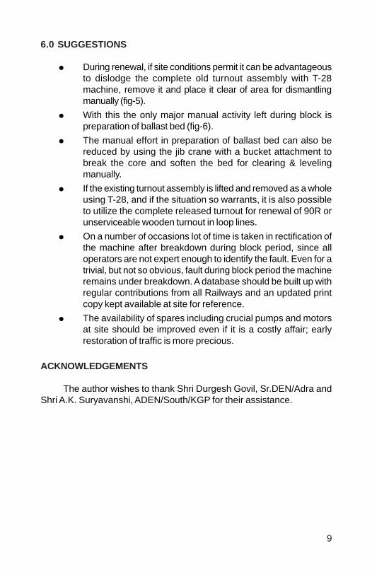
9
6.0 SUGGESTIONS
During renewal, if site conditions permit it can be advantageousto dislodge the complete old turnout assembly with T-28machine, remove it and place it clear of area for dismantlingmanually (fig-5).With this the only major manual activity left during block ispreparation of ballast bed (fig-6).The manual effort in preparation of ballast bed can also bereduced by using the jib crane with a bucket attachment tobreak the core and soften the bed for clearing & levelingmanually.If the existing turnout assembly is lifted and removed as a wholeusing T-28, and if the situation so warrants, it is also possibleto utilize the complete released turnout for renewal of 90R orunserviceable wooden turnout in loop lines.On a number of occasions lot of time is taken in rectification ofthe machine after breakdown during block period, since alloperators are not expert enough to identify the fault. Even for atrivial, but not so obvious, fault during block period the machineremains under breakdown. A database should be built up withregular contributions from all Railways and an updated printcopy kept available at site for reference.The availability of spares including crucial pumps and motorsat site should be improved even if it is a costly affair; earlyrestoration of traffic is more precious.
ACKNOWLEDGEMENTS
The author wishes to thank Shri Durgesh Govil, Sr.DEN/Adra andShri A.K. Suryavanshi, ADEN/South/KGP for their assistance.

10
Fig-1T-28 portals in clamped position over the new assembly
Fig-2Laying the new assembly in position

11
Fig-3Aligning the new assembly after laying
Fig-4Sketch of south end crossover of NSI yard
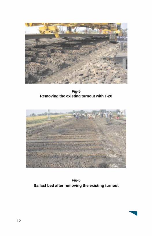
12
Fig-5Removing the existing turnout with T-28
Fig-6Ballast bed after removing the existing turnout
Vinod
Placed Image
1
LAYING OF DIAMOND CROSSING ONPSC SLEEPERS USING T-28 MACHINE ON
INDIAN RAILWAYS
VIVEK KUMAR GUPTA*
SYNOPSIS
Maintenance of Turnouts and cross overs which are essentialadjuncts of track structure has been a challenge to P-way Engineers.These special layouts need more than routine attention especiallyafter introduction of modern track structure consisting of concretesleepers, elastic fastenings and mechanized maintenance practices.Mumbai Division of Central Railway took the lead and DiamondCrossings on PSC layouts was laid using T-28 machine first time onIndian Railways on 10.01.2002. Author in this paper discussesvarious considerations while planning to replace the existing speciallayout laid on wooden sleepers with PSC sleepers and also givesdetails of problems encountered, remedial measures etc.
1.0 INTRODUCTION
Turn outs and cross over are essential adjuncts of a trackstructure, which are provided to permit the rolling stock to pass fromone line to another. The existence of these special layouts aremandatory due to consideration of change over from one line toanother. They are also considered to be weak link in the track owingto special characteristics such as difficult geometry, configuration,layout and maintainability. Improvement in the turnout design andgeometry has been a problematic area for railway track Engineerdue to safety and riding comfort considerations.
2.0 T-28 BASIC CHARACTERISTICS:
Indian Railways have procured points and crossings changingmachines manufactured by M/s. Ameca of Italy for laying of turnoutson PSC sleepers. It consists of 2 nos. self propelled portal cranes,2 sets of motorized/non motorized rail trollies and a jib crane. Theportal crane permits adjustments of span and height and can beworked on crawler chains.
* Secretary to GM, Central Railway
2
3.0 GENERAL DETAILS OF A DIAMOND CROSSING
A square crossing is formed when the tracks cross one anotherat right angle. The square crossings are to be avoided whereverpossible since the gaps in the running rails for wheel flanges beingopposite to each other cause severe jolting to vehicles resulting inrapid wear of the crossings and also damage to rolling stock onaccount of the heavy impact.
A Diamond crossing where the angle of the inter-section is lessthan the right angle is laid whenever track crossing becomesinescapable. A long flat diamond especially curved one is not adesirable feature in track as this type of layouts is very much apt toderailment since gaps at elbow of the obtuse crossings, which isexcessive in flat diamonds, may permit wheel to turn and take thewrong side of the nose. Similarly, if the angle of the intersection ofdiamond crossing is very acute, the possibility of derailment becomesgreater since the noses of the 2 obtuse crossings are nearly oppositeto each other and excessive gaps at elbow causes a perceptibledrop of the wheels running over a diamond. Indian Railways trackmanual, therefore, specify that diamond crossings should notnormally be flatter or less acute than 1 in 8½.
4.0. REQUIREMENT OF MINIMUM TRACK CENTERS TOACHIEVE GEOMETRICALLY GOOD LAY OUT OF ACROSS OVER
Indian Railways have stipulated to have 1 in 12 turnouts on allpassenger running lines, because of lesser angular crossings andhigher lead radius. For obtuse crossings, the requirement is,however, different as discussed in para 3.0 above. It is not desirableto have flatter diamond. The requirement of 1 in 12 turnout forcross overs and 1 in 8½ for diamond brings a contradiction in thedesirable features of a change over point. It therefore, becomesmandatory to design change over points with 1 in 12 on both endsand 1 in 8½ in between.
The need to have a junction of 1 in 12 and 1 in 8½ lay outrequires minimum track centers between two parallel tracks to havea good geometry. To have connecting curve of the radius of 1 in 8½turn out (232.32 m), minimum track centers required is 4.815 m.This is minimum track center requirement for achieving theoreticallycorrect geometry of a lay out. If the track centers are less than4.815 m, it becomes indeterminate solution and impossible to lay across over of different crossing angle between the tracks.

3
5.0 MECHANISED RELAYING OF DIAMOND CROSSING-VIS-MANUAL RELAYING:
Mechanised laying of track is superior to manual relaying inmany ways. Apart from better quality in terms of proper spacing,squaring of sleepers, ensuring adequate ballast cushion below thebottom of sleepers, it also ensures proper handling of rails andsleeper components.
Above aspects are still more important for laying of turn outsand specials such as diamond crossings etc. Over a period of time,due to the tendency of creep, the original track geometry getsdisturbed from its original position. The problem is more acute incases of multiple lines where making corrections at one particularspot would mean changes in the entire layout of the area. Diamondcrossing connects 3 lines and it is practically impossible to manuallyimprove the geometry of the layout of the 3 lines simultaneously.With the help of T-28 machines, it is possible to tackle the entirelayout and make necessary corrections in connecting curves betweenthe turnout and diamond crossing. Track centers between twoadjoining lines are very important and a small variation/error/changein track center gets amplified 12 times while calculating the overalllength of turnout. Since making connection would mean shifting ofentire assembly, it is possible only by mechanised means. It is,therefore, a must to replace existing special layouts like diamondcrossing using mechanised means only to affect any improvementin geometry of area deteriorated over a long passage of time.
6.0 PLANNING AND EXECUTION OF WORK OFREPLACEMENT BY T-28:
Figure 1
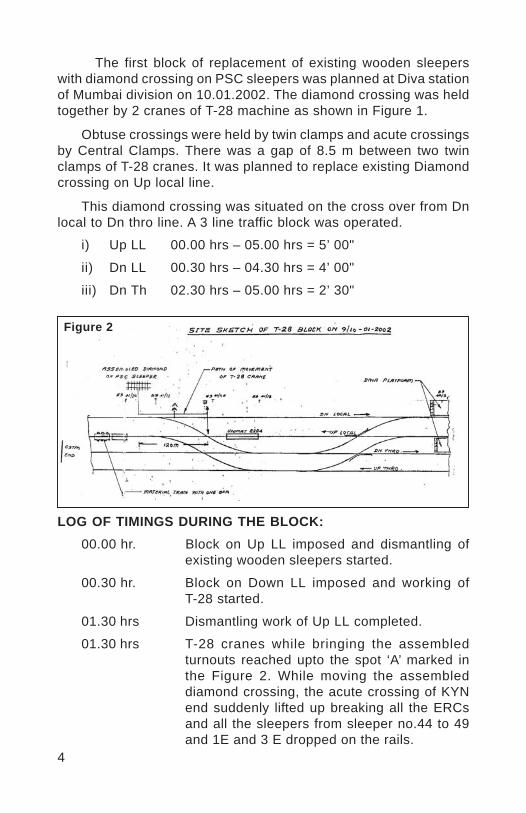
4
The first block of replacement of existing wooden sleeperswith diamond crossing on PSC sleepers was planned at Diva stationof Mumbai division on 10.01.2002. The diamond crossing was heldtogether by 2 cranes of T-28 machine as shown in Figure 1.
Obtuse crossings were held by twin clamps and acute crossingsby Central Clamps. There was a gap of 8.5 m between two twinclamps of T-28 cranes. It was planned to replace existing Diamondcrossing on Up local line.
This diamond crossing was situated on the cross over from Dnlocal to Dn thro line. A 3 line traffic block was operated.
i) Up LL 00.00 hrs – 05.00 hrs = 5’ 00"
ii) Dn LL 00.30 hrs – 04.30 hrs = 4’ 00"
iii) Dn Th 02.30 hrs – 05.00 hrs = 2’ 30"
LOG OF TIMINGS DURING THE BLOCK:00.00 hr. Block on Up LL imposed and dismantling of
existing wooden sleepers started.
00.30 hr. Block on Down LL imposed and working ofT-28 started.
01.30 hrs Dismantling work of Up LL completed.
01.30 hrs T-28 cranes while bringing the assembledturnouts reached upto the spot ‘A’ marked inthe Figure 2. While moving the assembleddiamond crossing, the acute crossing of KYNend suddenly lifted up breaking all the ERCsand all the sleepers from sleeper no.44 to 49and 1E and 3 E dropped on the rails.
Figure 2
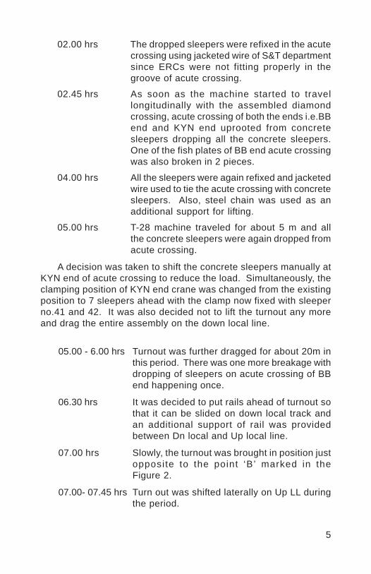
5
02.00 hrs The dropped sleepers were refixed in the acutecrossing using jacketed wire of S&T departmentsince ERCs were not fitting properly in thegroove of acute crossing.
02.45 hrs As soon as the machine started to travellongitudinally with the assembled diamondcrossing, acute crossing of both the ends i.e.BBend and KYN end uprooted from concretesleepers dropping all the concrete sleepers.One of the fish plates of BB end acute crossingwas also broken in 2 pieces.
04.00 hrs All the sleepers were again refixed and jacketedwire used to tie the acute crossing with concretesleepers. Also, steel chain was used as anadditional support for lifting.
05.00 hrs T-28 machine traveled for about 5 m and allthe concrete sleepers were again dropped fromacute crossing.
A decision was taken to shift the concrete sleepers manually atKYN end of acute crossing to reduce the load. Simultaneously, theclamping position of KYN end crane was changed from the existingposition to 7 sleepers ahead with the clamp now fixed with sleeperno.41 and 42. It was also decided not to lift the turnout any moreand drag the entire assembly on the down local line.
05.00 - 6.00 hrs Turnout was further dragged for about 20m inthis period. There was one more breakage withdropping of sleepers on acute crossing of BBend happening once.
06.30 hrs It was decided to put rails ahead of turnout sothat it can be slided on down local track andan additional support of rail was providedbetween Dn local and Up local line.
07.00 hrs Slowly, the turnout was brought in position justopposite to the point ‘B’ marked in theFigure 2.
07.00- 07.45 hrs Turn out was shifted laterally on Up LL duringthe period.
6
07.55 hrs Block on Dn Local cleared and material trainstanding at Home Signal of Dn local admitted.
08.00 -09.00 hrs Adjustment in the alignment of turnout wascarried out and T-28 cranes taken ahead afterunclamping at KYN end.
09.30 hrs T-28 cranes taken out between Up LL and DnThru’ lines.
09.55 hrs Track given fit after attending the alignmentand fixing of acute crossing etc.
7.0 PROBLEMS ENCOUNTERED AND PROBABLE CAUSE OFFAILURES.
As discussed in para 6.0 above, while moving the assembleddiamond crossing on cess, fa i lure in form of suddendisproportionate lifting of acute crossing of one end occurred whicheventually resulted in breaking up of all the ERCs and falling downof sleeper no.44 to 49, 1E, 2E and 3E. The sleepers werereassembled and another attempt was made to carry the assembleddiamond crossing to the position. However, second attempt alsofailed and acute crossings of both ends lifted higher than the obtusecrossing ends and sleepers dropped. The work then had to becarried out by manually shifting the sleepers ahead and placingthem in position.
This type of failure was not anticipated and the reasons for thefailures were analyzed in detail. The total length of the diamondcrossing was about 37 metres which was matching with the lengthof turn out which can be tackled with a set of T-28 cranes(2 nos).The design of diamond crossing consist of 2 obtuse crossings and2 acute crossings with sleeper no.41 upto 54 being the same as of1 in 8½ turn out as per RDSO design no. T-4867. There are,however, two such sets as against the one in simple 1 in 8½ turnout. The central 41 sleepers are different and specially designedfor obtuse crossing. The clamping position of the diamond crossingwas planned as of simple turn out with central clamp tied nearacute crossing and twin clamps near the obtuse crossing.
The failure of this arrangement occurred most probably due torigidity of the layout as a whole. Obtuse crossing being CMS,offered lot of resistance against rotat ional movement ofunsynchronized T-28 cranes movement. There was no way that
7
both T-28 cranes (which work independently) could be synchronizedfor longitudinal or lateral movement of the assembly on the cess.The movement of assembly on crawler chains of the T-28 machine,resulted in uneven load distribution on various components ofassembly. Diamond crossing assembly, when moved as a completelayout by the T-28 cranes with the twin clamps, holding the structurenear the obtuse crossing, formed a framed structure having highmodulus of elasticity and permitting lesser deflection. It could notabsorb unsynchronized movement and uneven load distribution. Theend clamps holding acute crossing portion worked independentlywith excessive amplitudes eventually resulting in breaking up ofERCs and dropping down of sleepers.
8.0 LAYING WITH MODIFIED ARRANGEMENT.
After analyzing the various reasons for the failures, it wasdecided to modify the clamping and balancing position of thediamond crossings. Additional clamping and balancing points wereintroduced as given in figure 3.
Figure 3
The main features of the modified arrangements were as under:
i) The diamond crossing was divided into 2 portions with oneportion holding one acute crossing and 2 obtuse crossing andanother portion only one acute crossing.
ii) Additional rail pieces with PSC sleepers were joined to makeit workable with T-28 cranes.
8
iii) A special clamp was provided near the heel of the acutecrossing. The clamp was fabricated using 100 lb doubleheaded rail pieces of 4.75 metres long joined together by 6connecting bolts of 31 mm dia x 275 mm long.
iv) The gripping chains provided with machines were also usedto balance the layout and provided midway. These chains werevery useful in maintaining the balance of the layout as anassembly.
v) The travel of cranes from the point of assembly to the actualpoint of placement was kept minimum and also groundundulations were made up to avoid uneven load distributionon the assembly.
With the above methodology, diamond crossings could beeasily tackled using T-28 cranes.
9.0 CONCLUSION:
Availability of PSC sleeper layouts for various specials shouldbe used in the right perspective in the endeavour to achieve perfectgeometry of these specials. The maintainability and reliability ofthese layouts with CMS crossing and PSC sleepers is very high ascompared to conventional wooden layouts. However, utmost careis required to lay these specials geometrically correct, for whichproper study of the various parameters and constraints are required.
Vinod
Placed Image
1
FUTURE STRATEGIES FORMANPOWER PLANNING WITH ADOPTION OF
MECHANISED MAINTENANCE OF TRACK
J. C. PARIHAR*YOGESH WADHWA**BALDEV SINGH***
SYNOPSIS
Traditionally, maintenance of track has been a manpower-orientedactivity. With the introduction of more and more track machines anddue to heavier track structure, the scope of manual efforts isdiminishing day by day. An attempt has been made through this paperto analyse mechanisation vis-à-vis manpower by taking a live exampleof various maintenance activities undertaken in the section ofSr. Section Engineer (P. Way) on N F Railway.
1.0 PRESENT SCENARIO
The manpower for maintenance of track is worked out on the basisof the Gang strength formula evolved by the special committee. Thecommittee has given weightage to the ETKM and other factors. Theother factors include the traffic density factor, formation factor, thealignment factor and the rainfall factor. The values allotted to thesefactors are fixed by the committee, which limits the scope of theformula and does not provide for the fewer inputs required by today’strack. The today’s track caters for a larger number of high-speed trainsfor passenger traffic and the goods trains running at a speed upto100 Kmph. In the near future, these loads, speeds and the number oftrains are going to increase further and, therefore, the scene hasundergone a complete change since the evolution of the SpecialCommittee Formula.
On the other hand, the inputs have also undergone vast variationby way of deployment of track machines in a big way, the trackstructure with higher UTS and poundage rails laid over concretesleepers including the concrete sleeper turnouts, increased ballastcushion and larger size of ballast. The difficult to maintain ST sleeper
* Chief Track Engineer, NF Rly** Dy. Chief Engineer/TD, NF Rly*** Divisional Engineer/I,Rangiya, NF Rly
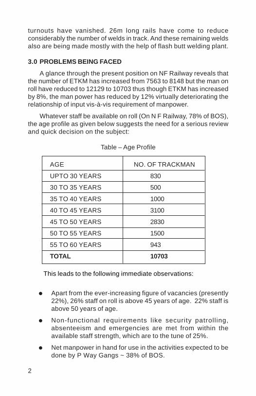
2
turnouts have vanished. 26m long rails have come to reduceconsiderably the number of welds in track. And these remaining weldsalso are being made mostly with the help of flash butt welding plant.
3.0 PROBLEMS BEING FACED
A glance through the present position on NF Railway reveals thatthe number of ETKM has increased from 7563 to 8148 but the man onroll have reduced to 12129 to 10703 thus though ETKM has increasedby 8%, the man power has reduced by 12% virtually deteriorating therelationship of input vis-à-vis requirement of manpower.
Whatever staff be available on roll (On N F Railway, 78% of BOS),the age profile as given below suggests the need for a serious reviewand quick decision on the subject:
Table – Age Profile
AGE NO. OF TRACKMAN
UPTO 30 YEARS 830
30 TO 35 YEARS 500
35 TO 40 YEARS 1000
40 TO 45 YEARS 3100
45 TO 50 YEARS 2830
50 TO 55 YEARS 1500
55 TO 60 YEARS 943
TOTAL 10703
This leads to the following immediate observations:
Apart from the ever-increasing figure of vacancies (presently22%), 26% staff on roll is above 45 years of age. 22% staff isabove 50 years of age.
Non-functional requirements l ike security patroll ing,absenteeism and emergencies are met from within theavailable staff strength, which are to the tune of 25%.
Net manpower in hand for use in the activities expected to bedone by P Way Gangs ~ 38% of BOS.

3
3.0 THE ISSUE
This problem cannot be sorted out through conventional processof recruitment because:
Recruitment procedures lay stress on education orientedselection procedure. The higher education is not conducivefor manual labour.
Educated new recruits would not prefer to work in P WayGangs.
Through this system of recruitment, though, we would becollecting a workforce of literate personnel oriented towardswhite-collar jobs. The requirement of track maintenance wouldnot be addressed.
Thus, without any material benefits, the system will be financiallyoverburdened due to fresh recruitments if wide-ranging changes arenot made in the recruitment policy. The effect of this situation is thatthe track maintenance activity is put to backseat to be able to facethe routine constraints with available resources. Resultantly, the CivilEngg. Deptt. of Railways is having large force of unskilled workersyet under-equipped to keep pace with the growing demands of thecompetitive world of transport systems of today.
4.0 POSSIBLE REMEDIES
We as a Railway system, the biggest of its kind in the World,have to grow, advance and prove our safety and growth record to standin competition with other modes of transport. Fifteen years back, therewas virtually paralyzed road transport system and negligible air trafficin the country but the enormous growth of these sectors is posingthreats. To achieve this, we have to find workable solution to thisissue, which can be possible with the following policy decisions:
(i) Minimize the labour intensive departmental activities – doingmaximum works with the machines for better quality andprecision and off loading the non-safety items to the trade.
(ii) Review the gang strength formula to accommodate thisimperative need – reduce this strength in lieu of machinesand the contractual agencies and 20% of the balance berecruited through ITI qualified personnel. The recruitment ofITI qualified candidates will provide the opportunity to have

4
technically qualified persons out of multiskilled pool of trainedpersonnel.
(iii) Reduce the over age of the people as the working on trackrequires lot of physical exertion which people above 45 yearsof age can not give. For this, attractive avenues can be openedfor going to other departments requiring lesser physicalexertion in doing their duties.
(iv) There is huge burden of patrolling on track because of adverselaw & order situation and climatic conditions in the N.F.Region. This activity can be offloaded by patrolling with amodified wagon attached to light engine and having the facilityof online monitors. This will minimize the requirement ofmanpower and provide better reliability and security. In aphased manner, service road along the embankment can bemade and security patrolling can be introduced through theseservice roads.
Besides these, there are other ways to address this problem:
1. Accept the present level of staff availability and planmaintenance through other means like regular manpowersupply contracts with proper conditions to ensure availabilityof staff of right age group and regular item rate contracts fordifferent activities of routine works; and
2. Use of more and more machines to minimize dependence onmanual labour – more skilled (ITI trained) personnel will benecessary for running these machines / mechanisation.
5.0 PROVISIONS OF SPECIAL COMMITTEE FORMULA
The gang strength shall depend more, than what is anticipatedand provided for in the Special Committee Formula, on GMT carried,Track Profile, Speeds and Climatic Factors. The Special CommitteeFormula provides for constant value factors for these important aspectsof track maintenance. For example, Traffic Density factor of 1.4 forheavily worked suburban or ghat sections / sections where annualtraffic density is more than 20 Million GTK per kilometer and over. Forall curves above 1.5°, same value of alignment factor is applicable forequal length of curved alignment though the effort required for upkeepof such curves varies largely. Similarly, the weightage for climaticfactors varies between 0.10 and 0.20, which does not provide adequaterelief towards the requirement of manpower to meet such situations.
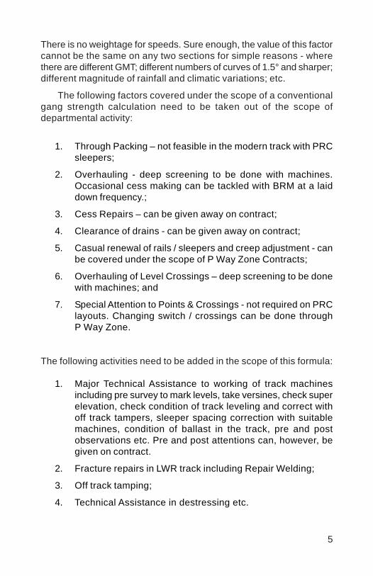
5
There is no weightage for speeds. Sure enough, the value of this factorcannot be the same on any two sections for simple reasons - wherethere are different GMT; different numbers of curves of 1.5° and sharper;different magnitude of rainfall and climatic variations; etc.
The following factors covered under the scope of a conventionalgang strength calculation need to be taken out of the scope ofdepartmental activity:
1. Through Packing – not feasible in the modern track with PRCsleepers;
2. Overhauling - deep screening to be done with machines.Occasional cess making can be tackled with BRM at a laiddown frequency.;
3. Cess Repairs – can be given away on contract;
4. Clearance of drains - can be given away on contract;
5. Casual renewal of rails / sleepers and creep adjustment - canbe covered under the scope of P Way Zone Contracts;
6. Overhauling of Level Crossings – deep screening to be donewith machines; and
7. Special Attention to Points & Crossings - not required on PRClayouts. Changing switch / crossings can be done throughP Way Zone.
The following activities need to be added in the scope of this formula:
1. Major Technical Assistance to working of track machinesincluding pre survey to mark levels, take versines, check superelevation, check condition of track leveling and correct withoff track tampers, sleeper spacing correction with suitablemachines, condition of ballast in the track, pre and postobservations etc. Pre and post attentions can, however, begiven on contract.
2. Fracture repairs in LWR track including Repair Welding;
3. Off track tamping;
4. Technical Assistance in destressing etc.
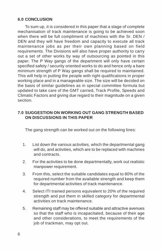
6
6.0 CONCLUSION
To sum up, it is considered in this paper that a stage of completemechanisation of track maintenance is going to be achieved soonwhen there will be full compliment of machines with the Sr. DEN /DEN and they will have freedom and capacity to execute all trackmaintenance jobs as per their own planning based on fieldrequirements. The Divisions will also have proper authority to carryout a set of other works by way of outsourcing as pointed in thispaper. The P Way gangs of the department will only have certainspecified safety / security oriented works to do and hence only a bareminimum strength of P Way gangs shall be required to maintained.This will help in putting the people with right qualifications in properworking place and in a manageable size. The size will be decided onthe basis of similar guidelines as in special committee formula butupdated to take care of the GMT carried, Track Profile, Speeds andClimatic Factors and giving due regard to their magnitude on a givensection.
7.0 SUGGESTION ON WORKING OUT GANG STRENGTH BASEDON DISCUSSIONS IN THIS PAPER
The gang strength can be worked out on the following lines:
1. List down the various activities, which the departmental gangwill do, and activities, which are to be replaced with machinesand contracts.
2. For the activities to be done departmentally, work out realisticmanpower requirement.
3. From this, select the suitable candidates equal to 80% of therequired number from the available strength and keep themfor departmental activities of track maintenance.
4. Select ITI trained persons equivalent to 20% of the requiredstrength and put them in skilled category for departmentalactivities on track maintenance.
5. Remaining staff may be offered suitable and attractive avenuesso that the staff who is incapacitated, because of their ageand other considerations, to meet the requirements of thejob of trackman, may opt out.
7
6. Deploy the machines for all the activities identified to be donewith machines in such a manner that the machines areavailable to all the units of track maintenances on the Railwaysto meet their requirement realistically in view of the work load,traffic density, climatic conditions and block availability. Inaddition, keep some machines as stand by to cater to therequirement of emergencies, break down and other unforeseenthings.
7. Make it a system that the contracts for contractual activitiescan be finalized smoothly and systematically on a regularbasis.
Vinod
Placed Image
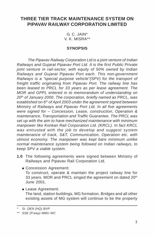
1
THREE TIER TRACK MAINTENANCE SYSTEM ONPIPAVAV RAILWAY CORPORATION LIMITED
G. C. JAIN*V. K. MISRA**
SYNOPSIS
The Pipavav Railway Corporation Ltd is a joint venture of IndianRailways and Gujarat Pipavav Port Ltd. It is the first Public Privatejoint venture in rail-sector, with equity of 50% owned by IndianRailways and Gujarat Pipavav Port each. This non-governmentRailways is a “special purpose vehicle”(SPV) for the transport offreight traffic originating from Pipavav Port. The railway line hasbeen leased to PRCL for 33 years as per lease agreement. TheMOR and GPPL entered in to memorandum of understanding on20th of January 2000. The corporation, briefly named as PRCL, wasestablished on 6th of April 2003 under the agreement signed betweenMinistry of Railways and Pipavav Port Ltd. In all five agreementswere signed for – Concession, Lease, construction, Operation &maintenance, Transportation and Traffic Guarantee. The PRCL wasset up with the aim to have mechanized maintenance with minimummanpower like Konkan Rail Corporation Ltd. (KRCL). In fact KRCLwas entrusted with the job to develop and suggest systemmaintenance of track, S&T, Communication, Operation etc. withutmost economy. The manpower was kept bare minimum unlikenormal maintenance system being followed on Indian railways, tokeep SPV a viable system.
* Sr. DEN (HQ) BVP** SSE (P.way) MMU WC
1.0 The following agreements were signed between Ministry ofRailways and Pipavav Rail Corporation Ltd.
Concession Agreement:To construct, operate & maintain the project railway line for33 years. MOR and PRCL singed the agreement on dated 20th
June 2001.
Lease Agreement:The land, station buildings, MG formation, Bridges and all otherexisting assets of MG system will continue to be the property

2
of IR These assets have been made available to the SPV onlease basis at a pre specified rental after considering capital-at-charge at historical cost.
Construction Agreement:To construct the project line on the cost basis as applicable tointer-department for Railways.
Operation and Maintenance (O&M) Agreement:To operate and maintain the efficiency project l ine forconcession agreement period for seamless operation,enhancing and smooth operation of freight traffic.
Transportation and Traffic Guarantee:It guarantees to PRCL the rolling stock from WR & rail cargofrom GPPL.
2.0 MAINTENANCE SYSTEMUnder the O&M agreement signed between Ministry ofRailways and PRCL, the following infrastructures are coveredfor maintenance:
1. Track (3 tier track maintenance)2. S&T (mobile maintenance)3. Communication (mobile maintenance)4. Operation (by Western Railway)5. Medical (by Western Railway)6. Security (by Western Railway)
Out of the above infrastructure maintenance, the Authors aretrying to highlight the maintenance system adopted in regardto track maintenance by adopting 3 tier track maintenancesystem as contained in IRPWM under para 203(1) (CS 53 dated24/04/2000).
3.0 3-TIER TRACK MAINTENANCEThe track structure consists of 52kg 90 UTS rails laid on 60kgPRC sleepers with M+7 density. Ballast cushion of 300 mm isprovided. Curved switches of 1 in 12 & 1 in 8 ½, 52kg on PRCsleepers have been provided on the entire route. All Points &crossings are panel interlocked. LWR track is provided in allpermitted locations.
Track is one of the most important components for any Railwaysystem. Choice of track components affects degree ofmaintenance required during service. Keeping this aspect in
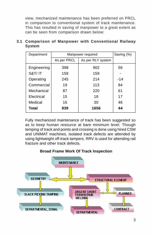
3
view, mechanized maintenance has been preferred on PRCLin comparison to conventional system of track maintenance.This has resulted in saving of manpower to a great extent ascan be seen from comparison drawn below:
3.1 Comparison of Manpower with Conventional RailwaySystem
Fully mechanized maintenance of track has been suggested soas to keep human resource at bare minimum level. Thoughtemping of track and points and crossing is done using hired CSMand UNIMAT machines, isolated track defects are attended byusing lightweight off-track tampers. RRV is used for attending railfracture and other track defects.
Broad Frame Work Of Track Inspection
MAINTENANCE
SLACK PICKING TAMPING
DEPARTMENTAL, ZONAL
STRUCTURAL ELEMENT
URGENT SHORT TERM REPAIR WELDING
PLANNED
DEPARTMENTAL CONTRACT
GEOMETRY
Department Manpower required Saving (%)
As per PRCL As per RLY system
Engineering 398 902 56S&T/ IT 159 159 -Operating 245 214 -14Commercial 19 113 84Mechanical 87 220 61Electrical 15 18 17Medical 16 30 46Total 939 1656 44
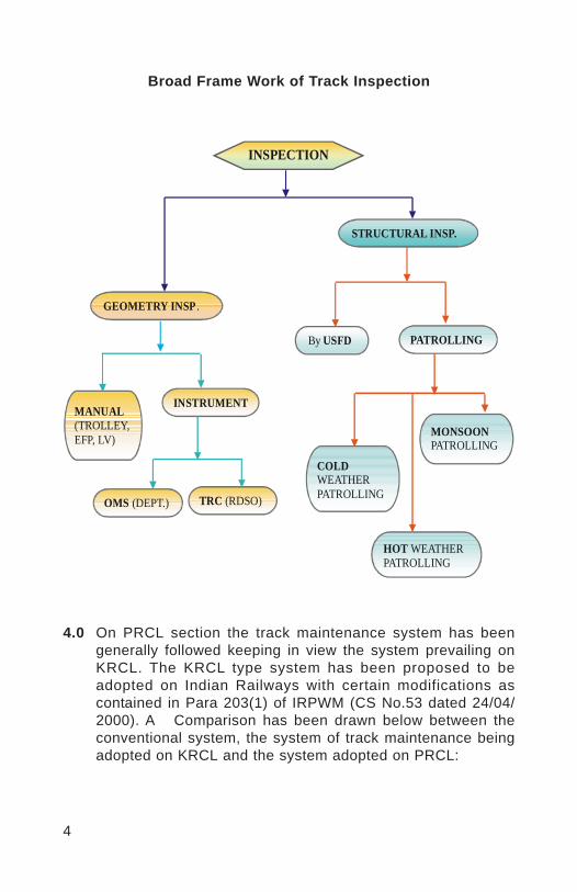
4
INSPECTION
GEOMETRY INSP .
STRUCTURAL INSP.
MANUAL (TROLLEY, EFP, LV)
INSTRUMENT
By USFD PATROLLING
OMS (DEPT.) TRC (RDSO)
COLD WEATHER PATROLLING
HOT WEATHER PATROLLING
MONSOON PATROLLING
Broad Frame Work of Track Inspection
4.0 On PRCL section the track maintenance system has beengenerally followed keeping in view the system prevailing onKRCL. The KRCL type system has been proposed to beadopted on Indian Railways with certain modifications ascontained in Para 203(1) of IRPWM (CS No.53 dated 24/04/2000). A Comparison has been drawn below between theconventional system, the system of track maintenance beingadopted on KRCL and the system adopted on PRCL:
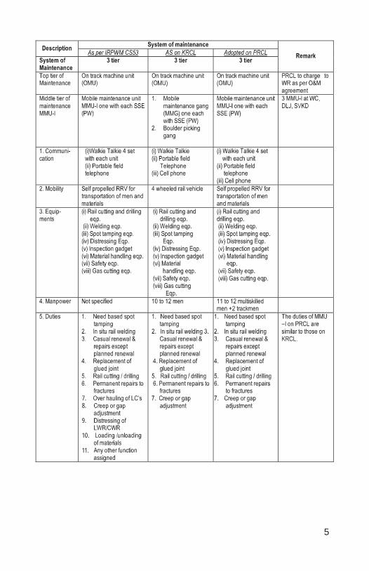
5
7.8.
9.
10.
11.
6
5.0 VARIOUS LEVELS OF TRACK MAINTENANCE:
The track maintenance has been divided into 3-tier system
Tier I - On track machines:Looking to traffic density, it will be necessary to deploy CSM,Unimat, BRM once in two years. Western Railway will providethe track machines required for the maintenance as requiredunder the O&M agreement.
Tier II - Mobile maintenance units:
The Mobile Maintenances Units comprise of two units. Unit-Ihas been provided with each Sectional Engineer (P. way) andcovers a length of approx. 80 to 90 Kms. This unit is basicallyprovided with a Rail-cum-Road vehicle (RRV). This RRV canmove on track as well as on road. It can be off tracked within5 minutes in midsection on level crossings and with specialarrangement at other places by exchanging private numberunder special instructions. RRV is equipped with welding set,small track machines for urgent repairs, 2 Nos. rail pieces of6.5 Mtrs./glued joints for replacement incase of rail fracture,casual renewal of rails in emergencies and transportation ofP way materials like all maintenance equipment, fittings, scrap.This unit is named as MMU-I.
Unit No. 2 named as MMU II ; This is kept under Senior SectionEngineer (P. Way-Workshop) and under direct control of ADEN.This unit is provided with one mini truck. This unit has 8 menmostly artisan staff. This unit is aimed to repair the small trackmachines at site in emergencies and failures. In case of majorrepair of small track machines, the MMU-II unit transports thesame to the workshop of the Sr. Sectional Engineer (P. wayWorkshop). After major repairs, the small track machines aretransported back to the Section Engineer for use at site.
Tier III - Mobile maintenance gangs (MMGs):
These are basically DTM gangs having jurisdiction of 21 to 23kms. There are 12 trackmen in each MMG, headed by oneP.way Supervisor (PWS). Works like picking up slacks, weedingout grass, making up ballast profile etc. is done by MMGs. TheMMGs are using push trollies for day-to-day movement in thesection, however motor trollies with trailers are being procured.Motor trollies with trailers will run in corridor blocks for daily

7
movement of gangs in section for maintenance. Motor trollieswith trailers will be off loaded at site of work and placed ontrack after attending the work site by exchange of privatenumber and code words.
6.0 P. Way organization:
The entire 262 km length of PRCL has been entrusted tothree Senior Section Engineer (P. Way) and one SSE (W). EachSenior Section Engineer (P. Way) is supported by SectionEngineer (MMU) and two sectional SEs/JEs. Each SE/JE hastwo Mobile Maintenance Gangs (MMGs). Each MMG has onePermanent Supervisor and 12 trackmen. It has a beat of approx22 km each. Track safetymen with a beat of approx 7 km areprovided separately. Organization chart is shown below. EachSenior Section Engineer (P. Way) and Section Engineer (MMU)has approx 87 kms of single line track under his control.
ADEN
SSE (P.WAY)
SSE (P.WAY)
SSE (P.WAY)
JE(P.WAY)
JE(P.WAY)
SE(P.WAY) MMU I
SSE (P.WAY) MMU II
SE(W)
JE(P.WAY)
JE(P.WAY)
SE(P.WAY) MMU I
JE(P.WAY)
JE(P.WAY)
SE(P.WAY) MMU I
MMG 1+12
MMG 1+12
MMG 1+12
MMG 1+12
MMU I gang
MMG 1+12
MMG
MMG 1+12
MMG 1+12
MMG 1+12
MMU I gang
MMG 1+12
MMG 1+12
MMG 1+12
MMG 1+12
MMU I gang
MMU II gang
8
7.0 Outsourcing activity
Since the manpower on PRCL is bare minimum certain activitiessimilar to those on KRCL have been permitted by Railway Boardfor letting out on contracts:
i. Cess repair by earthwork.ii. Loading, unloading and dressing of ballast.iii. Over hauling of level crossing.iv. Casual renewal of rails and sleepers except in case of
rail fracture and it’s welding.v. Greasing of ERCs.vi. Deep and shallow screening.vii. Cleaning of drains.viii. Distressing of LWRs.ix. Pre and post tamping attentions.x. Track renewals.xi. Attending works at site of accident.xii. Cleaning waterways of bridges.xiii. Weeding out grass and clearing of bushes.xiv. Transportation of materials from depot to site of work.xv. Painting of hectometer posts, curve, P&C, SEJ, Indication
boards etc.xvi. Casual changing of rubber pads and other fittings.xvii. Minor Cess repairs.xviii. Cleaning of crib ballast for effective drainage.xix. Any other unforeseen activity not covered in the scope of
MMU/ MMG.
8.0 SYSTEM OF MONSOON, SUMMER, WINTER PATROLLING:
The PRCL is located under temperature Zone III as such thetrackmen of MMGs are used for carrying out monsoon, winter,summer patrolling. No additional manpower is needed forpatrolling, stationary watchman at vulnerable locations.
9.0 INSPECTION SCHEDULE:
The inspection schedules laid down on Indian railways are notfollowed on PRCL. Railway Board has approved the followinginspection schedules for PRCL.
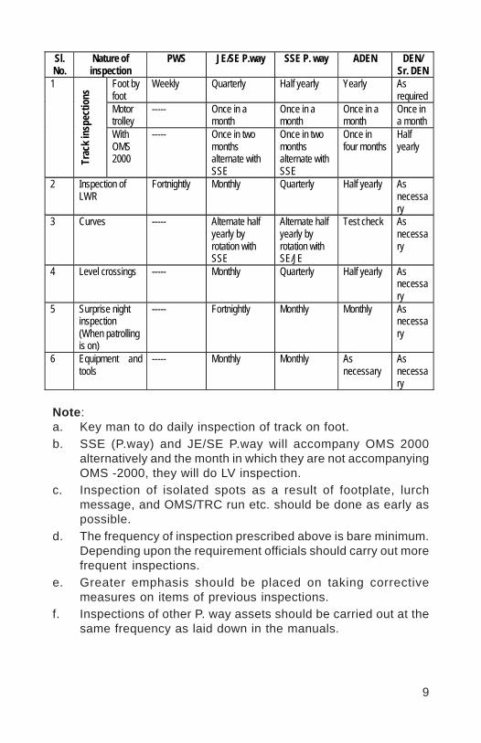
9
Sl. No.
Nature of inspection
PWS JE/SE P.way SSE P. way ADEN DEN/ Sr. DEN
Foot by foot
Weekly Quarterly Half yearly Yearly As required
Motor trolley
----- Once in a month
Once in a month
Once in a month
Once in a month
1
Trac
k ins
pect
ions
With OMS 2000
----- Once in two months alternate with SSE
Once in two months alternate with SSE
Once in four months
Half yearly
2 Inspection of LWR
Fortnightly Monthly Quarterly Half yearly As necessary
3 Curves ----- Alternate half yearly by rotation with SSE
Alternate half yearly by rotation with SE/JE
Test check As necessary
4 Level crossings ----- Monthly Quarterly Half yearly As necessary
5 Surprise night inspection (When patrolling is on)
----- Fortnightly Monthly Monthly As necessary
6 Equipment and tools
----- Monthly Monthly As necessary
As necessary
Note:a. Key man to do daily inspection of track on foot.b. SSE (P.way) and JE/SE P.way will accompany OMS 2000
alternatively and the month in which they are not accompanyingOMS -2000, they will do LV inspection.
c. Inspection of isolated spots as a result of footplate, lurchmessage, and OMS/TRC run etc. should be done as early aspossible.
d. The frequency of inspection prescribed above is bare minimum.Depending upon the requirement officials should carry out morefrequent inspections.
e. Greater emphasis should be placed on taking correctivemeasures on items of previous inspections.
f. Inspections of other P. way assets should be carried out at thesame frequency as laid down in the manuals.
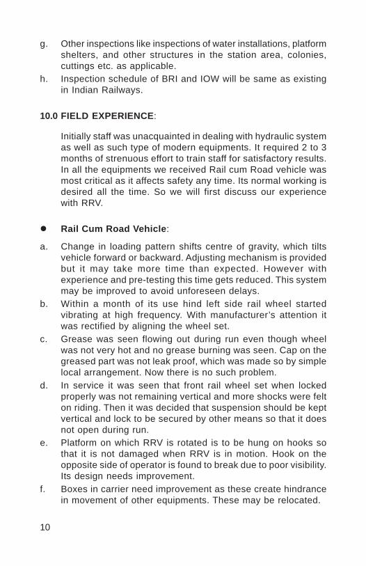
10
g. Other inspections like inspections of water installations, platformshelters, and other structures in the station area, colonies,cuttings etc. as applicable.
h. Inspection schedule of BRI and IOW will be same as existingin Indian Railways.
10.0 FIELD EXPERIENCE:
Initially staff was unacquainted in dealing with hydraulic systemas well as such type of modern equipments. It required 2 to 3months of strenuous effort to train staff for satisfactory results.In all the equipments we received Rail cum Road vehicle wasmost critical as it affects safety any time. Its normal working isdesired all the time. So we will first discuss our experiencewith RRV.
Rail Cum Road Vehicle:
a. Change in loading pattern shifts centre of gravity, which tiltsvehicle forward or backward. Adjusting mechanism is providedbut it may take more time than expected. However withexperience and pre-testing this time gets reduced. This systemmay be improved to avoid unforeseen delays.
b. Within a month of its use hind left side rail wheel startedvibrating at high frequency. With manufacturer’s attention itwas rectified by aligning the wheel set.
c. Grease was seen flowing out during run even though wheelwas not very hot and no grease burning was seen. Cap on thegreased part was not leak proof, which was made so by simplelocal arrangement. Now there is no such problem.
d. In service it was seen that front rail wheel set when lockedproperly was not remaining vertical and more shocks were felton riding. Then it was decided that suspension should be keptvertical and lock to be secured by other means so that it doesnot open during run.
e. Platform on which RRV is rotated is to be hung on hooks sothat it is not damaged when RRV is in motion. Hook on theopposite side of operator is found to break due to poor visibility.Its design needs improvement.
f. Boxes in carrier need improvement as these create hindrancein movement of other equipments. These may be relocated.

11
Overall performance of RRV is very satisfactory. RRV can beon tracked in less than 15 minutes off tracked in 5-7 minutes.Its truck portion is very reliable. Reliability of other parts maybe improved with experience.
Pandrol clip applicator cum extractor:
Pandrol cl ip appl icator cum extractor is designed byShri V K Misra SSE/MMU/WC under the able guidance ofSr. DEN (HQ)/BVP Shri G C Jain the presenter to reduce impactload on Pandrol clips. Pandrol clips can be applied with thisequipment by one man with max. 30 kg force (by body wt.).Weight of equipment is 6 kg and can be reduced further. It canapply Pandrol clip at the same speed as by hammer withoutdamaging pandrol clip. It can also extract pandrol clip that arenot jammed heavily.
Clip Extraction stage 1 Clip Extraction stage 2
11.0 CONCLUSION:
The mechanized track maintenance by 3-tier system of trackmaintenance is effective and economical. However, the systemcan work only when full complement of small track machinesfor day-to-day maintenance are available. For this the mobileworkshop plays a very important role and its effectiveness isthe pivotal of the entire track maintenance organization. In casethe small track machines are not maintained on day-to-day basisthe maintenance under the system may prove failure.
Vinod
Placed Image
1
MECHANISED MAINTENANCE OF TRACK INBANGALORE DIVISION - A UNIQUE CONCEPT
AMITH GARG*
SYNOPSIS
The mechanised maintenance of track on KRCL pattern hasbeen adopted on the Bangalore division of South Western Railwayon the newly constructed line from Dharmavaram to Penakonda viaPuttaparthy (the abode of SAI BABA).
The Railway Safety Review Committee 1998 has recommendedthe adoption of KRCL pattern of mechanized track maintenance overthe entire IR. This has been accepted by the Ministry of Railways.However, it has been adopted for the first time only in Bangaloredivision.
The Section engineer has been provided with a mobilemaintenance vehicle (RMV) and a party of Multiskilled men and has ajurisdiction of 50km. These staff are trained for operation of RMV,welding, rail cutting and drilling machines, operation of off tracktampers and other skilled jobs.
The system of mechanised maintenance adopted by KRCL andtransplanted as it is in Bangalore division on a small section is workingvery satisfactorily.
1.0 INTRODUCTION
Of the 63000 route km of track in the Indian Railways, only 52kmcan be strictly classified as track which is being maintained adoptingmechanised maintenance in its literary and true sense. Reference isto be made to the prescriptions of I.R.P.Way Manual Correction Slipno. 53 dated 24.4.2000 and no. 67 dated 24.4.2001.
The mechanised maintenance of track was adopted on theBangalore division of South Western Railway on the newly constructedline from Dharmavaram to Penakonda via Puttaparthy (the abode ofSAI BABA). The system has been virtually transplanted as it is fromthe system of maintenance, which has been tried on Konkan Railwayfor the last six years successfully.
* Sr DEN/Coord/Bangalore, SW Rly
2
Railway Safety Review Committee 1998: recommended that “ IRshould work quickly towards adopting the pattern of track maintenanceestablished by KRC where each gang has been provided with a mobilemaintenance vehicle and has a jurisdiction of 40km. Complete switchover to machine maintenance should be made a mission area, to begiven priority on par with any other activity connected with track.”
The Ministry of Railways accepted the recommendation. Haveany steps been taken to achieve this goal is a moot point.
It was thought that the traditional system of manual maintenanceshall not be applicable for track on concrete sleepers with modernfeatures. A new approach was attempted for mechanised maintenanceon the KRCL keeping in mind the geographical peculiarities of thesystem and the modern track structure adopted.
The widely held but misplaced conception is that packing byon-track tampers is mechanised maintenance.
2.0 PRESCRIPTIONS OF IR PWAY MANUAL
2.1 Extract from CS no. 67
Para 1408 (1): (a) : Concrete sleeper track should be maintainedby heavy duty on track tampers.
For spot attention/slack picking, multi purpose tampers and offtrack tampers shall be used. Where off track tampers are not available,as an interim measure, the packing may be done with the help ofcrow bars/beaters duly taking care that the concrete sleepers are notdamaged.
2.2 Extract from CS no. 53 :
Para 203 (1): The track should be maintained either by conventionalsystem of maintenance or by 3 tier system of maintenance.
3.0 OBSERVATIONS:
It is clear that a PRC sleeper track should be maintained adoptingmechanised maintenance. However, only the first step of themechanised maintenance system has been used all over the IR whereas steps 2 & 3 related to MMU’s and mobile gangs have beencompletely ignored.

3
The bigger issue that needs attention is that even though:
1. Mechanisation of track maintenance started 30 years back withthe import of tamping machines.
2. Concrete sleepers are the byword in track relaying andconstruction. This year 1 Crore concrete sleepers shall beproduced.
3. 52/60kg rails, fan shaped layouts, thick web switches etc arelaid on nearly 40,000 km of track.
4. Enormous social changes like unwillingness to do manual labour,unwillingness to live in far flung areas, increase in the averageage of trackmen to nearly 50 years, heavy track structure etc.
5. The inbuilt weaknesses of manual system of track maintenanceare well known.
no planned action has been taken to put in place a well structuredsystem of track maintenance based on mechanised methods.
3.1 As per para 228 of IRPWay Manual
3-tier system of track maintenance
3-tier system of track maintenance shall be adopted onsections nominated for mechanised track maintenance.
This shall consist of the following 3 tiers of track maintenance:1. On track machines (OMU)2. Mobile Maintenance Unit ( MMU)3. Sectional gangs
The Mobile maintenance units shall comprise of two groups.
1. MMU-1: One for each PWl section2. MMU-2: One for each subdivision
MMU-1 shall be a Rail cum road vehicle with a PWl in-chargewith a jurisdiction of 40-50km double line and 90-100km single line forvarious works including need based spot tamping and in-situ railwelding.
MMU-2 shall be a road vehicle based unit with eachsubdivision for reconditioning of turnouts and minor repairs to theequipments of MMU.
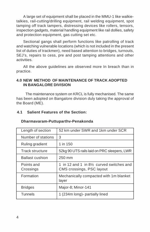
4
A large set of equipment shall be placed in the MMU-1 like walkie-talkies, rail-cutting/drilling equipment, rail welding equipment, spottamping off track tampers, distressing devices like rollers, tensors,inspection gadgets, material handling equipment like rail dollies, safetyand protection equipment, gas cutting set etc.
Sectional gangs shall perform functions like patrolling of trackand watching vulnerable locations (which is not included in the presentlist of duties of trackmen), need based attention to bridges, turnouts,SEJ’s, repairs to cess, pre and post tamping attentions and otheractivities.
All the above guidelines are observed more In breach than inpractice.
4.0 NEW METHOD OF MAINTENANCE OF TRACK ADOPTEDIN BANGALORE DIVISION
The maintenance system on KRCL is fully mechanised. The samehas been adopted on Bangalore division duly taking the approval ofthe Board (ME).
4.1 Salient Features of the Section:
Dharmavaram-Puttuparthv-Penakonda
Length of section 52 km under SWR and 1km under SCR
Number of stations 3
Ruling gradient 1 in 150
Track structure 52kg 90 UTS rails laid on PRC sleepers, LWR
Ballast cushion 250 mm
Points and 1 in 12 and 1 in 8½ curved switches andCrossings CMS crossings, PSC layout
Formation Mechanically compacted with 1m blanketlayer
Bridges Major-8; Minor-141
Tunnels 1 (234m long)- partially lined
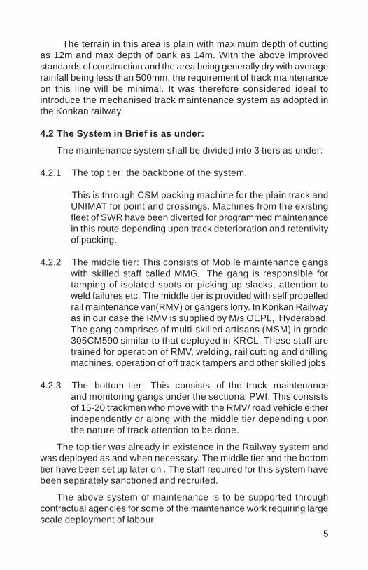
5
The terrain in this area is plain with maximum depth of cuttingas 12m and max depth of bank as 14m. With the above improvedstandards of construction and the area being generally dry with averagerainfall being less than 500mm, the requirement of track maintenanceon this line will be minimal. It was therefore considered ideal tointroduce the mechanised track maintenance system as adopted inthe Konkan railway.
4.2 The System in Brief is as under:
The maintenance system shall be divided into 3 tiers as under:
4.2.1 The top tier: the backbone of the system.
This is through CSM packing machine for the plain track andUNIMAT for point and crossings. Machines from the existingfleet of SWR have been diverted for programmed maintenancein this route depending upon track deterioration and retentivityof packing.
4.2.2 The middle tier: This consists of Mobile maintenance gangswith skilled staff called MMG. The gang is responsible fortamping of isolated spots or picking up slacks, attention toweld failures etc. The middle tier is provided with self propelledrail maintenance van(RMV) or gangers lorry. In Konkan Railwayas in our case the RMV is supplied by M/s OEPL, Hyderabad.The gang comprises of multi-skilled artisans (MSM) in grade305CM590 similar to that deployed in KRCL. These staff aretrained for operation of RMV, welding, rail cutting and drillingmachines, operation of off track tampers and other skilled jobs.
4.2.3 The bottom tier: This consists of the track maintenanceand monitoring gangs under the sectional PWI. This consistsof 15-20 trackmen who move with the RMV/ road vehicle eitherindependently or along with the middle tier depending uponthe nature of track attention to be done.
The top tier was already in existence in the Railway system andwas deployed as and when necessary. The middle tier and the bottomtier have been set up later on . The staff required for this system havebeen separately sanctioned and recruited.
The above system of maintenance is to be supported throughcontractual agencies for some of the maintenance work requiring largescale deployment of labour.
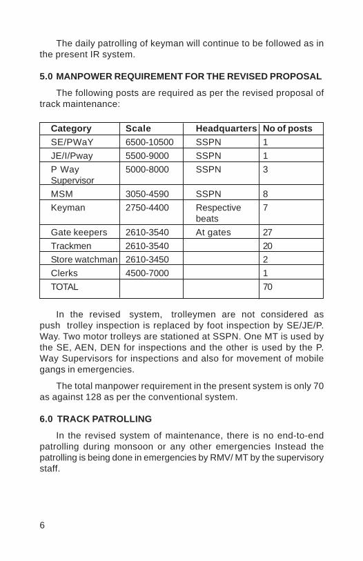
6
The daily patrolling of keyman will continue to be followed as inthe present IR system.
5.0 MANPOWER REQUIREMENT FOR THE REVISED PROPOSAL
The following posts are required as per the revised proposal oftrack maintenance:
Category Scale Headquarters No of postsSE/PWaY 6500-10500 SSPN 1JE/I/Pway 5500-9000 SSPN 1P Way 5000-8000 SSPN 3SupervisorMSM 3050-4590 SSPN 8Keyman 2750-4400 Respective 7
beatsGate keepers 2610-3540 At gates 27Trackmen 2610-3540 20Store watchman 2610-3450 2Clerks 4500-7000 1TOTAL 70
In the revised system, trolleymen are not considered aspush trolley inspection is replaced by foot inspection by SE/JE/P.Way. Two motor trolleys are stationed at SSPN. One MT is used bythe SE, AEN, DEN for inspections and the other is used by the P.Way Supervisors for inspections and also for movement of mobilegangs in emergencies.
The total manpower requirement in the present system is only 70as against 128 as per the conventional system.
6.0 TRACK PATROLLING
In the revised system of maintenance, there is no end-to-endpatrolling during monsoon or any other emergencies Instead thepatrolling is being done in emergencies by RMV/ MT by the supervisorystaff.
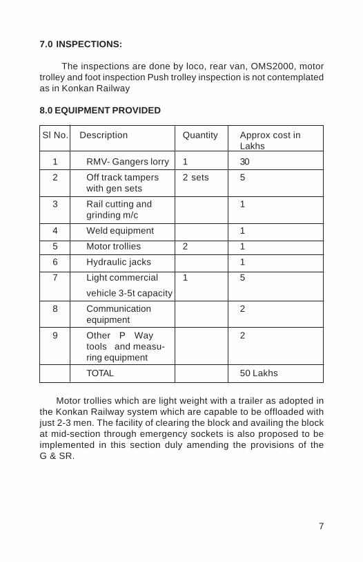
7
7.0 INSPECTIONS:
The inspections are done by loco, rear van, OMS2000, motortrolley and foot inspection Push trolley inspection is not contemplatedas in Konkan Railway
8.0 EQUIPMENT PROVIDED
Sl No. Description Quantity Approx cost inLakhs
1 RMV- Gangers lorry 1 30
2 Off track tampers 2 sets 5with gen sets
3 Rail cutting and 1grinding m/c
4 Weld equipment 1
5 Motor trollies 2 1
6 Hydraulic jacks 1
7 Light commercial 1 5
vehicle 3-5t capacity
8 Communication 2equipment
9 Other P Way 2tools and measu-ring equipment
TOTAL 50 Lakhs
Motor trollies which are light weight with a trailer as adopted inthe Konkan Railway system which are capable to be offloaded withjust 2-3 men. The facility of clearing the block and availing the blockat mid-section through emergency sockets is also proposed to beimplemented in this section duly amending the provisions of theG & SR.

8
9.0 COMMUNICATION FACILITY:
As the maintenance is based on mobile gangs, effectivecommunication is essential for the supervisors. In addition to therailway facility to all supervisors, mobile communication like walkie-talkie for the supervisory staff with a central VHF station at SSPNcovering the entire range from PKD to DMMM has been provided
10.0 EXPERIENCE AND CONCLUSION:
The Section Engineers / P. Way are extremely satisfied with theworking of this system. There are demands from almost all sectionsthat similar practice should be adopted in their sections too. TheSEs/P. Way are more confident in attending the routine maintenanceworks which have become more organised and the chaos whichnormally prevails when emergencies are attended has virtuallyvanished.
The system of mechanised maintenance adopted by KRCL andtransplanted as it is in Bangalore division on a small section is workingvery satisfactorily. It is essential that the issue of improved andadvanced maintenance practices is discussed at all levels and themechanised system of track maintenance is adopted in the IR in itstrue spirit and substance.
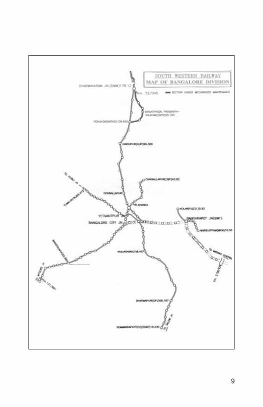
9
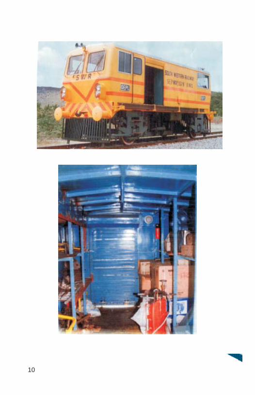
10
Vinod
Placed Image
1
MECHANISATION OF TRACK MAINTENANCECAN IT BE OPTIMIZED BY
MOBILE MECHANISED UNIT (MMU)
A.K.CHAKRABORTY*
SYNOPSIS
Indian Railways is facing a growing demand for higher speedpassenger traffic and heavy freight trains. Therefore, it is essentialto make efforts for optimizing the track maintenance practices toensure safe and comfortable travelling for men and material. OnIndian Railways, the maintenance of track is done simultaneouslyby machines and manual methods. In order to evolve an economicaland suitable track maintenance practice, the time has come toundertake steps for optimized maintenance of track. This paperdeals with the activities, work involvement, output and possibilitiesof Mobile Mechanised Unit ( MMU ) as a step in the right directionfor optimization of track maintenance practices.
1. INTRODUCTION
Track maintenance practice is basically changing in nature. Inlate eighties, the world Railway system was going through a periodof renaissance. New high speed lines were laid in Europe, Japanand USA. On Indian Railways , the introduction of concrete sleeperswith elastic fastenings and 90 UTS rails proved to be a remarkableimprovement in track structure. Before such modernization of track,the conventional track was being maintained mainly by manualmethods and in some important areas track machines weredeployed , although these areas could not be considered as fullymechanized track maintenance zone. The track mechanizationprocess started on Indian Railways, about 30 years ago. Presentlyover 370 on-track machines of various types are deployed in IndianRailways for laying and maintenance of track.
Various small track machines are also being used formaintenance purpose. Usage of all these machines makes themaintenance system speedier and efficient. But so far optimization
* Section Engineer/Track Machine Cell,Track Machine and Monitoring Directorate, RDSO,Lucknow.
2
of track maintenance is concerned, a systematic and planned wayof track maintenance work is required which involves optimumefforts to be exercised for maintenance of track.
Area of track maintenance work may be broadly classified as :
1. Maintenance work by heavy on- track machines (OMU)2. Maintenance work by small track machines (MMU)3. Maintenance work by manual effort.
A fresh strategy for deployment of machines and manpowerfor optimum track maintenance is necessary to cater to thechanges in track technology accompanied by phenomenalincrease in traffic density and changed socio-economic conditionsof trackmen. Mobile mechanized unit is the most importantmachinery of mechanized track maintenance system. In thefollowing paragraph, the role of the MMU and the equipment ofthe MMU has been described emphasizing the importance of Rail-cum-Road vehicle (RCRV).
2. MMU ORGANISATION
The mobile maintenance unit consists of two group :
i) Group-I
Each PWI’s section of 40 to 50 Km of double lined track shallbe covered by Group-I. The headquarters of this group shallcoincide with that of the PWI/Incharge. The functions of this groupare :
a) Needbased spot tamping
b) In-situ rail welding.
c) Casual renewals and repairs except planned renewal.
d) Overhauling of level crossing.
e) Replacement of glued joints.
f) Rail cutting, drilling & chamfering.
g) Permanent repairs to fractures.
h) Creep or gap adjustment involving use of machines.
i) Destressing of LWR track.
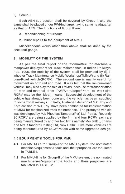
3
ii) Group-II
Each AEN-sub section shall be covered by Group-II and thesame shall be placed under PWI/Incharge having same headquarteras that of AEN. The functions of Group II are :
a. Reconditioning of turnouts
b. Minor repairs to the equipment of MMU.
Miscellaneous works other than above shall be done by thesectional gangs.
3. MOBILITY OF THE SYSTEM
As per the final report of the ‘Committee for machine &manpower deployment for Track Maintenance’ in Indian Railways,Feb, 1995, the mobility of the system shall be provided by (i) 8-wheeler Track Maintenance Mobile Workshop(TMMW) and (ii) Rail-cum-Road vehicle(RCRV). The second one is mainly useful formovement on both rail and road. It was felt that the rail-cum-roadvehicle may also play the role of TMMW because for transportationof men and material from PWI/Store/depot/ Yard to work site,RCRV may be the ideal means. Successful development of thevehicle has already been done and the vehicle has been suppliedto some zonal railways. Initially, Allahabad division of N.C. Rly andKota division of W.C.Rly have been nominated for implementationof MMU for mechanized track maintenance. The prototype vehiclewas developed by M/s Phooltas Tampers(Pvt) Ltd, Patna. Recently30 RCRV are being supplied by the firm and four RCRV each arebeing manufactured by another two firms namely M/s BHEL, Jhansiand M/s. Standard Costing Ltd, New Delhi. Five more vehicles arebeing manufactured by DCW/Patiala with some upgraded design.
4.0 EQUIPMENT & TOOLS FOR MMU
4.1 For MMU-I i.e for Group-I of the MMU system the nominatedmachines/equipment & tools and their purposes are tabulatedin TABLE-I.
4.2 For MMU-II i.e for Group-II of the MMU system, the nominatedmachineries/equipment & tools and their purposes aretabulated in TABLE-2.

4
TABLE-ILIST OF SMALL TRACK MACHINES FOR TRACK
MAINTENANCE WORK (FOR MMU-I WITH EACH PWI)SN Work Machine Qty.
1. Need based spot tamping with lifting and lining.
i. Off track hand held tampers with generator. ii. Hyd./Mech. Lifting jack. iii. Hyd. Track lifting cum slewing device.
1 Set 4 Sets 2 Sets
2. In-Situ rail welding i. Rail welding equipment. ii.Weld trimmer iii.Rail profile Weld Grinder.
2 Sets 1 Set 1 Set
3. Casual renewals and repairs except planned renewal.
i.Rail cutting machine (Abrasive/saw type) ii.Rail drilling machine iii. Track lifting jacks (hydraulic/mech.) iv. Various track tools like crow bars, beaters, rake ballast, rail tongue etc.
Already mentioned for other works
4. Overhauling of Level Crossing
i. Track lifting jack ( hyd./Mech. ) ii. Hyd. Track lifting cum slewing device. iii. Off track hand held tampers with Generator. iv. Various track tools like crow bars, beaters, rake ballast, rail tongue etc.
Already mentioned for other works
5. Replacement of Glued Joint i. Rail cutting machine (Abrasive/Saw type). ii. Rail drilling machine. iii. Rail welding equipment. iv.Weld trimmer for LWR/CWR v.Rail profile Weld Grinder.
Already mentioned for other works
6. Rail cutting/Drilling and Chamfering.
i. Rail cutting machine (Abrasive & Saw type). ii. Rail drilling machine. iii. Chamfering Kit.
1 No. each 1 No. 1 Set
7. Permanent repair to fracture
i. Rail cutting machine (Abrasive/Saw type). ii. Rail drilling machine. iii. Rail welding equipment. iv.Weld trimmer v.Rail profile Weld Grinder. vi Hyd.rail tensor.
Alrady mentioned for other works
8. Creep or gap adjustment i.Rail creep adjuster. ii.Gap gauge.
1 Set 1 No.
9. Destressing of LWR/CWR i. Rail cutting machine (Abrasive/Saw type). ii. Rail drilling machine. iii. Rail welding equipment. iv.Weld trimmer v.Rail profile Weld Grinder. vi Hyd.rail tensor. vii. Destressing rollers. viii. Wooden mallet.
As mentioned for other works 2 Sets 1 Complete set for destressing 3 Kms.
10. Material Handling (Loading and Unloading of materials)
i.Rail dolly. ii. Monorail wheel barrow
6 Nos. 2 Nos.
11. Inspection Gadgets: (For inspection and measurement of track parameters and components).
1. Gauge cum level. 2. Rail thermometer. 3. P-Way Inspection Kit 4. Vernier Caliper 5. Micrometer
1 No. 1 No. 1 No. 1 No. 1 No.
12. Safety and Protection 1.Warning System 2. Red Banner Flag 3. Red Hand Signal Flag 4.Green Hand Signal Flag 5.Detonators
1 Set 2 Nos. 2 Nos. 2 Nos. 1 Pack (10 nos.)
13. Communication Equipment 1.Walkie Talkie 2.Portable field telephone
4 Sets 1 set
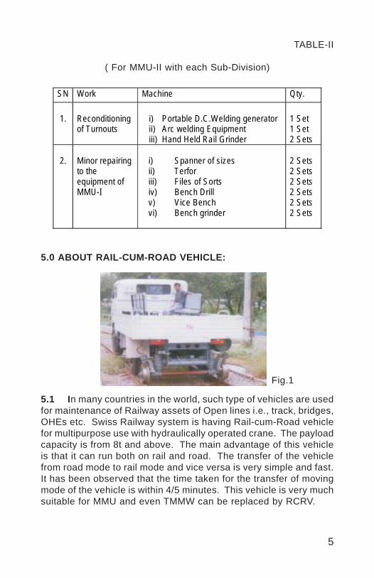
5
TABLE-II
( For MMU-II with each Sub-Division)
SN Work Machine Qty.
1.
Reconditioning of Turnouts
i) Portable D.C.Welding generator ii) Arc welding Equipment iii) Hand Held Rail Grinder
1 Set 1 Set 2 Sets
2.
Minor repairing to the equipment of MMU-I
i) Spanner of sizes ii) Terfor iii) Files of Sorts iv) Bench Drill v) Vice Bench vi) Bench grinder
2 Sets 2 Sets 2 Sets 2 Sets 2 Sets 2 Sets
5.0 ABOUT RAIL-CUM-ROAD VEHICLE:
5.1 In many countries in the world, such type of vehicles are usedfor maintenance of Railway assets of Open lines i.e., track, bridges,OHEs etc. Swiss Railway system is having Rail-cum-Road vehiclefor multipurpose use with hydraulically operated crane. The payloadcapacity is from 8t and above. The main advantage of this vehicleis that it can run both on rail and road. The transfer of the vehiclefrom road mode to rail mode and vice versa is very simple and fast.It has been observed that the time taken for the transfer of movingmode of the vehicle is within 4/5 minutes. This vehicle is very muchsuitable for MMU and even TMMW can be replaced by RCRV.
Fig.1
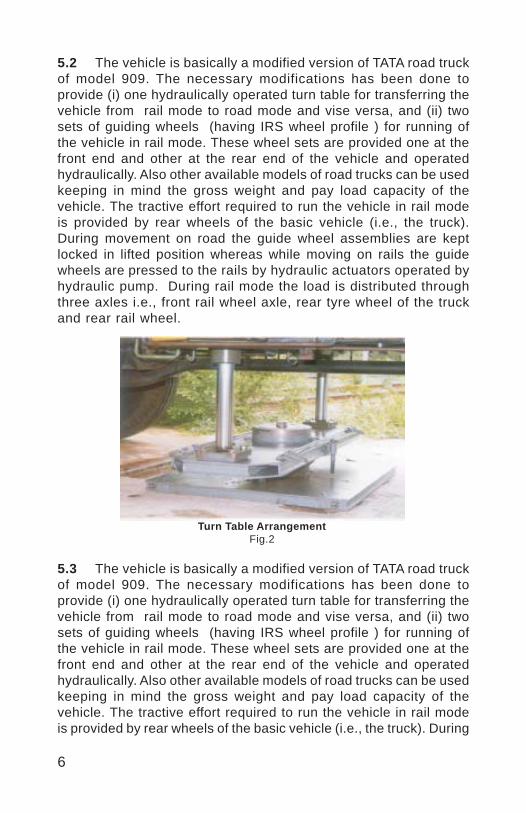
6
5.2 The vehicle is basically a modified version of TATA road truckof model 909. The necessary modifications has been done toprovide (i) one hydraulically operated turn table for transferring thevehicle from rail mode to road mode and vise versa, and (ii) twosets of guiding wheels (having IRS wheel profile ) for running ofthe vehicle in rail mode. These wheel sets are provided one at thefront end and other at the rear end of the vehicle and operatedhydraulically. Also other available models of road trucks can be usedkeeping in mind the gross weight and pay load capacity of thevehicle. The tractive effort required to run the vehicle in rail modeis provided by rear wheels of the basic vehicle (i.e., the truck).During movement on road the guide wheel assemblies are keptlocked in lifted position whereas while moving on rails the guidewheels are pressed to the rails by hydraulic actuators operated byhydraulic pump. During rail mode the load is distributed throughthree axles i.e., front rail wheel axle, rear tyre wheel of the truckand rear rail wheel.
Turn Table ArrangementFig.2
5.3 The vehicle is basically a modified version of TATA road truckof model 909. The necessary modifications has been done toprovide (i) one hydraulically operated turn table for transferring thevehicle from rail mode to road mode and vise versa, and (ii) twosets of guiding wheels (having IRS wheel profile ) for running ofthe vehicle in rail mode. These wheel sets are provided one at thefront end and other at the rear end of the vehicle and operatedhydraulically. Also other available models of road trucks can be usedkeeping in mind the gross weight and pay load capacity of thevehicle. The tractive effort required to run the vehicle in rail modeis provided by rear wheels of the basic vehicle (i.e., the truck). During

7
movement on road the guide wheel assemblies are kept locked inlifted position whereas while moving on rails the guide wheels arepressed to the rails by hydraulic actuators operated by hydraulic pump.During rail mode the load is distributed through three axles i.e., frontrail wheel axle, rear tyre wheel of the truck and rear rail wheel.
Rear rail wheel assemblyFig.3
Load distribution with sprung load of 7700 Kg (in loaded condition)
Front rail wheel Front tyre wheel Rear tyre wheel Rear rail wheel
(in Rail mode)Fig. 4
5.4 The main technical features of the vehicle are:i) Overall length : 7250 mm
ii) Gross weight : 9.0 t
iii) Pay load capacity : 3.5 t
iv) Basic vehicle : TATA model 909 truck
v) Speed : 60 kmph on rail and 80 kmph on road
vi) Seating Arrangement : 1+2 at driver’s cab and 4 at driver’sback cabin, 4 at loading platform’sseat.
2.451

8
The vehicle is suitable for transporting small track machines,materials and workmen to the work site within a short time. For thisreason, the vehicle is also useful for emergency repair of trackslike in case of rail fracture, buckling etc. For fast restoration of trafficafter derailment-damage, RCRV can be a better tool.
6.0 IMPORTANT FUNCTIONS:
6.1 One of the most important functions of the MMU system isspot tamping. The spot tamping is a part of directed trackmaintenance (DTM). As and where required, the isolatedportions of the track can be effectively attended to improvecertain parameters like unevenness, cross level and alignmentby using hand held off track tampers. With the use of suchtampers concrete sleeper / flat bottom sleeper track can betamped with an average progress of 40 to 50 sleepers perhour. During tamping, correction of lateral alignment, verticalprofile and cross level can be done by using hydraulic tracklifting and slewing device (TRALIS). All these equipment arehaving approved vendors and are already being used by zonalrailways.
6.2 A recent development of common electrical power pack foroperation of rail drilling machine, rail cutting machine ( bothsaw type and abrasive disc type ), weld trimmer and rail profileweld grinding machine makes these machines lighter in weightand operator-friendly. These machines are supposed to bekept in RCRV. On the other hand, the common power packwill considerably reduce the maintenance works as the primemovers of these machines are electrical motors in place ofindividual I.C. Engines.
7.0 PRESENT SCENARIO:
7.1 Railway Board decided to implement MMU initially on twodivisions i.e., Allahabad division of N.C..Rly. and Kota divisionof W.C. Rly.
7.2 Vide Railway Board’s letter no. 88/Track-III/TK/18 Vol. III Pt.dated 23.2.02 constituted MMU implementation committeecomprising of Director/IRICEN Pune, PCE/NCR, CE/Co-ord/WCR, CTE/WR & EDTM/RDSO.
9
7.3 The committee of implementation of MMU on Indian RailwaysPassed some important recommendations at the meeting heldon 25.8.04 at New Delhi. Some important conclusion arereproduced below:
(i) Review of Exprerience on KTT & ALD Division (MMU-I with RCRV)
As per the details of using the MMU on the two divisions followingwas observed:
(a) On ALD Division the line capacity utilization on A’ Route is approx120%, however the same is little less than 100% on KTT Division.Board have been monitoring the progress on monthly basis, inspite of this, the total utilization RCRV based MMU-I on ALDDivision has been only of the order of 30%, of which about 10%only has been on rail. Sr. DEN/C/ALD explained that they find itmore practical to use road truck for movement of men, materialand equipment rather than RCRV due to very heavy down timefor the same and due to RCRV’s limitation of movement on railon paper line clear. In a over saturated section like Allahabaddivision movement of RCRV is just not practical. Use of RCRVon rail i.e. 10% of 30% which is only about 3% of the time.Assuming that the design features of RCRV could be improvedand down time controlled, even then the use of RCRV on rail isnot likely to increase significantly and thus it will continue to workpredominantly as a road vehicle.
On KTT Division the utilization has been better. Total utilizationon KTT Division is of the order of 65%-70%, of which the useon rail has been about 30%, i.e. 70%*30% = 21% overall.However the KTT Division has also reported about excessivedown time and its limitation of movement on rail.
(b) The duties assigned to MMU-I indicate that the maximumworkload of transporting Small Track Machines (STMs), handlingnew/released track material and man power are assigned to it.Therefore, reliable transportation for MMU-I is one of the keyissues for ensuring success of this system. Experience gainedon the use of Rail-cum-Road Vehicle (RCRV) on Kota Divisionand Allahabad Division highlighted some limitations of RCRV.These have been summarized below:
10
Various problems experienced by Kota and Allahabad Divisionin implementing MMU are briefly given below:
(i) Track circuiting and axle counter problems – Response ofRCRV in Track circuiting area is however improved but theaxle counter doesn’t count the axles of RCRV. The solution ofproviding 710 mm dia. solid wheel by Technical committeeRDSO seems to be impractical in as much as to accommodatesuch big diameter wheels under the chassis of road vehicle.
(ii) Infringement at Level crossings – During on-tracking/off-tracking, infringement on adjacent track on double line sectionwill require 5-10 minutes block up and down lines. On busyroutes, this becomes a big constraint in effective utilization ofRCRV during maintenance block period.
(iii) Pay Load & Seating Capacity – MMU-I has been assignedduties which need transportation of man, material andmachines. For works like casual renewals, overhauling of levelcrossings, fracture repairs etc. new material like sleepers, railsare required in addition to T&P, small machines and manpower. Thus, pay load limit of 3.5 tonnes of present RCRVwill not meet the requirement. In addition to this, seating spacefor required numbers of P.way man/technicians is also notavailable on RCRV. Loading/unloading of material is one ofthe duties assigned to MMU-I. Limited pay Load capacity of3.5 tonnes of RCRV will becomes a constraint. Increase inpay load capacity of RCRV will make the unit unwieldy. Withthis constraint, this vehicle can carry only about 4-6 workers,who may not be adequate to even unload the machinery andmaterial from the RCRV, let alone carry out the work at side.
Conclusion of the committee meeting: Looking into the problemsfaced with RCRV, the committee is of the opinion that transportationseparately by rail and road is a superior alternative. Fortransportation by rail, a self-propelled 8-wheeler unit with a longplatform, driving cab, a crane (of about 2.5 T capacity) and covered/open space will be much satisfactory arrangement.
Recommendations of the committee: Continuing with three tierstrack maintenance system on sections nominated for mechanizedmaintenance, each SSE (P.Way) may have two MMUs with sameduty list as proposed below. One MMU shall use self propelled 8-wheeler rail bound unit called Track Maintenance Mobile Workshop(TMMW)’. TMMW will have a long platform, driving cab, a crane
11
and covered/ open space for carrying man, material and equipmentto work sport. The design of such vehicle may be adopted suitably.
Following duty list of MMUs is proposed:
(i) Need based spot tamping.
(ii) In-situ rail welding.
(iii) Casual renewal and repair except planned renewals.
(iv) Replacement of glued joints.
(v) Rail cutting/drilling/chamfering.
(vi) Permanent repair to fractures.
(vii) Creep or gap adjustments involving use of machines.
(viii) Reconditioning of turnouts.
(ix) Minor repair of equipment of MMUs.
(x) Loading/unloading of material used in carrying out aboveassigned works.
(xi) Any other functions assigned.
8.0 CONCLUSION:
Implementation of MMU in most of the sections of IndianRailways is necessary. The time has come to opt for full fledgedmechanized track maintenance system. Manual maintenance hasbecome a herculean task and also the present average age of gangmen is in between 40 to 55 years which jeopardize the manualmaintenance system. At the same time it is essential to deploy theright maintenance practice with optimum effort.
Vinod
Placed Image

1
TRACK MECHANIZATION ON INDIAN RAILWAYS –THE MISSING LINKS
J.S. MUNDREY*
* Formerly Adviser, Civil Engineering, Railway Board, India.
In rail transport, Permanent Way constitutes the mostimportant part of the infrastructure, as it provides the permanentpath for rolling stock, transporting passenger and goods.
Indian Railways, in the last three decades have taken manyimportant initiatives for upgrading their track structure. Over 45,000km of track is now laid with concrete sleepers. Almost a millionconcrete sleepers are being laid every year on Indian Railways,which include sleepers on turnouts, level crossings, curves, bridgeapproaches etc.
Concrete sleepers can be best maintained with heavy on-tracktamping machines. Over the years, Indian Railways have acquireda large fleet of track machines for carrying out track maintenanceand renewal works. It is rather a paradox that a railway system,which can take pride in having the most modern, sophisticated andhighly productive track machines, in large number, also carries aburden of over two lakhs ill-equipped gangmen, who continue to workin the manner and with the same tools as used by their predecessorsalmost a century age. This is happening on account of the fact thatfor many of the track operation, Indian Railways, have not been ableto find an efficient and cost effective solution for mechanizedexecution of works.
The productivity of track machines is also required to befurther optimized by removing the bottlenecks coming in theirimproved performance.
The paper makes an in-depth analysis of the process of trackmechanization on Indian Railway. Steps that can be taken to carryout all track works, efficiently and economically by equipping trackmaintenance gangs with appropriate machines, have beensuggested. Hopefully with the new thrust on track mechanization,Indian Railways will be able to find a mechanized cost effectivesolution for execution of all track works, hither to being donemanually by the sectional gangs.
2
1.0 INDIAN RAILWAYS AND ITS TRACK STRUCTURE
Indian Railways with a route kilometerage of over 63,000kilometers and track kilometerage of over 1.1 lakh kilometers, isone of the largest networks in the railway world. Indian Railwayscarry out yearly track renewals of over 4,000 km, which is morethan the total track kilometerage of some of the smaller railwaysystems, like Bangladesh, Srilanka, Thailand or Malaysia.
Track structure on Indian Railways is being modernized on afast pace. The new track structure consists of heavy 60 kg/52 kg,90 UTS, continuously welded rails, laid on concrete sleepers withelastic fastening systems. Adequate ballast cushion, 30 to 35 cmdeep, is provided on all track renewals and on new constructions.Special care is being taken for the mechanical compaction of thesub-grade.
Out of 62000 km of broad gauge track, more than 45,000 km iswith long welded rails and concrete sleepers. The yearly productionof concrete sleepers is reaching a startling figure of over one crore.Turnout are being provided with concrete bearers. Over 15000turnouts are already laid with concrete sleepers. Concrete sleepershave been designed for almost all locations, including levelcrossings, curves, platform lines and for heavy axle-load high-density routes.
All track materials are being manufactured indigenously. Bhilairail rolling mill has now started rolling 65 m long rails. Jindal Steel& Power Ltd (JSPL) has put up a modern state of the art rail-rolling mill producing high quality rails of 120 m length. The millhas been equipped to weld rails into longer length of up to 480 m,by having an integrated flash butt welding plant. The rails areproposed to be transported, straight from the rolling mill to thetrack relaying sites, there-by saving large sums of money, normallyspent in rail handling. In addition the new system will avoiddamage to the rails, occurring during their handling at flash buttwelding plants/track laying sites.
By all standards, Indian Railway track structure comparesfavourably well with the best of the track on similar lines on theworld railway systems.

3
2.0 PRESENT SYSTEM OF TRACK MAINTENANCE,CONSTRUCTION AND RENEWAL.
Track maintenance system on Indian Railways is characterizedwith the existence of age-old sectional gangs having a jurisdictionof 6 to 10 km. On some sections, old two units of the sectionalgangs have been combined together to have longer beats withincreased gang strength. These sectional gangs still carry out mostof their track works with hand tools, which have changed little inthe last hundred years of railways existence.
Track maintenance of heavy track structure consisting ofconcrete sleepers and long welded rails is generally carried outwith the help of on-track tamping machines. These machines, whichlift, level, align and tamp the track all automatically, are deployedon a laid down schedule. The sectional gangs help in the workingof the tamping machines, in all their pre-tamping and post tampingoperations.
New track construction, are still being carried out by manualgangs, except that for tamping operations, on-track tampingmachines are sometimes employed by borrowing them from theopen line maintenance organizations. For track renewals, varioustypes of track renewal equipments are in use. They are in the formof PQRS units and track renewal trains (TRT).
For the renewal of points and crossings, T-28 cranes are beingdeployed to the extent available.
For deep screening ballast cleaning machines have beenpurchased. There are a few shoulder ballast cleaners also workingon Indian Railways.
While periodical tamping of modern concrete sleeper track hasmostly been taken over by on-track tamping machines, the positionin respect to deep screening of ballast and track renewals is farfrom satisfactory. Only 40% of the deep screening work is beingdone by machines, rest is done manually. The position is equallybad with track relaying, only 45% is done with the mechanizedequipment.
The work carried out by manual gangs is not only timeconsuming but of poor quality affecting the service life of the track.Track work is strenuous, hazardous, unsafe, in-compatible with theemerging social trends and thus is carried out very reluctantly bythe present day gangmen.
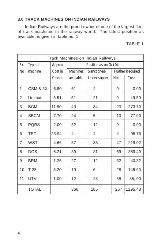
4
3.0 TRACK MACHINES ON INDIAN RAILWAYS
Indian Railways are the proud owner of one of the largest fleetof track machines in the railway world. The latest position asavailable, is given in table no. 1
TABLE-1
Track Machines on Indian RailwaysSr. Type of Approx Position as on Oct 04No machine Cost in Machines Sanctioned/ Further Required
Crores available Under supply Nos Cost
1 CSM & 3X 6.80 61 2 0 0.00
2 Unimat 5.51 51 21 9 49.59
3 BCM 11.90 40 34 23 273.70
4 SBCM 7.70 24 5 10 77.00
5 PQRS 2.00 32 12 0 0.00
6 TRT 23.94 4 4 4 95.76
7 WST 4.66 57 35 47 219.02
8 DGS 5.21 39 31 69 359.49
9 BRM 1.26 27 12 32 40.32
10 T 28 5.20 19 6 28 145.60
11 UTV 1.00 12 23 35 35,.00
TOTAL 366 185 257 1295.48
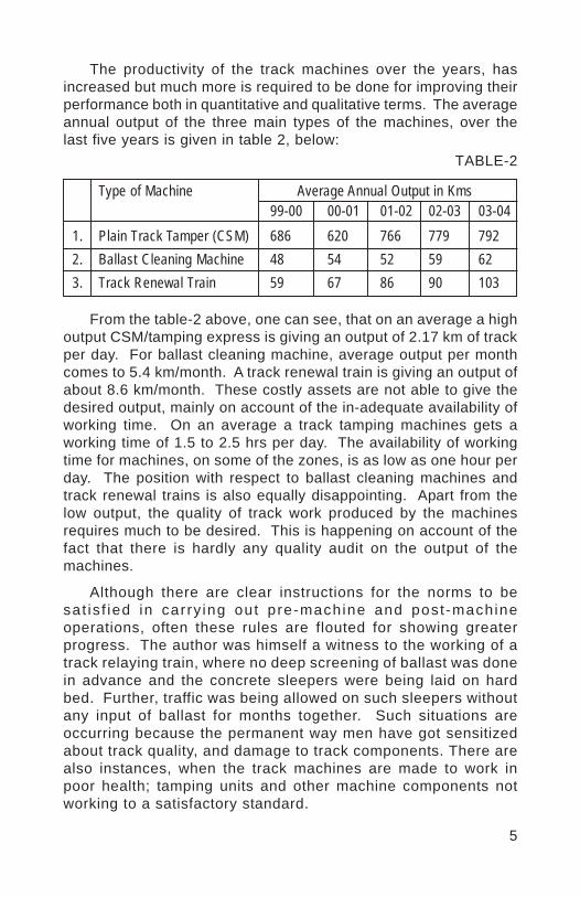
5
TABLE-2
From the table-2 above, one can see, that on an average a highoutput CSM/tamping express is giving an output of 2.17 km of trackper day. For ballast cleaning machine, average output per monthcomes to 5.4 km/month. A track renewal train is giving an output ofabout 8.6 km/month. These costly assets are not able to give thedesired output, mainly on account of the in-adequate availability ofworking time. On an average a track tamping machines gets aworking time of 1.5 to 2.5 hrs per day. The availability of workingtime for machines, on some of the zones, is as low as one hour perday. The position with respect to ballast cleaning machines andtrack renewal trains is also equally disappointing. Apart from thelow output, the quality of track work produced by the machinesrequires much to be desired. This is happening on account of thefact that there is hardly any quality audit on the output of themachines.
Although there are clear instructions for the norms to besat is f ied in carry ing out pre-machine and post -machineoperations, often these rules are flouted for showing greaterprogress. The author was himself a witness to the working of atrack relaying train, where no deep screening of ballast was donein advance and the concrete sleepers were being laid on hardbed. Further, traffic was being allowed on such sleepers withoutany input of ballast for months together. Such situations areoccurring because the permanent way men have got sensitizedabout track quality, and damage to track components. There arealso instances, when the track machines are made to work inpoor health; tamping units and other machine components notworking to a satisfactory standard.
The productivity of the track machines over the years, hasincreased but much more is required to be done for improving theirperformance both in quantitative and qualitative terms. The averageannual output of the three main types of the machines, over thelast five years is given in table 2, below:
Type of Machine Average Annual Output in Kms99-00 00-01 01-02 02-03 03-04
1. Plain Track Tamper (CSM) 686 620 766 779 7922. Ballast Cleaning Machine 48 54 52 59 623. Track Renewal Train 59 67 86 90 103
6
4.0 MEASURES TO OBTAIN BETTER QUALITY OUTPUT FORTRACK MACHINES
For improving the performance of these costly assets, some ofthe measures that can be taken are:
(a) Independent quality audit of the working of the machine.
(b) Systematic study for increasing the output of the track machine.In Europe it is quite common to introduce single line working forimproving the machine output. Most of the double lines inEurope have the provision of introducing single line working asand when required. Such provision should be made in all thedoubling works being done on Indian Railways.
(c) Study of the system being adopted by advanced countries toobtain better quality standards. The deployment of EM-SAT tracksurvey car and DGS machines along with the tamping machinesare the systems to be studied. On American rai l -roadconsiderable savings in ballast has been achieved by usingproper technology of ballast management deploying ballastdistribution system, consisting of ballast measuring and profilingmachines, ballast sweeper and pick up units and MFS machines.
5.0 SECTIONAL GANGS AND THEIR PERFORMANCE
While Indian Railways distinguish themselves in acquiringthe latest, state of the art, sophisticated and highly productivetrack maintenance machines in large number, they also sufferfrom the stigma of carrying the burden of over two lakhs ill-equipped gang men with low or no productivity. These menand women, continue to work in the manner and with the tools,as were used by their forefathers almost a century ago. Thisis happening on account of the fact that for many of the trackoperations, Indian Railways have not been able to find aneff ic ient and cost effect ive solut ion for their mechanizedexecution. At Annexure-1 is given the list of the task generallyperformed by sectional gangs on Indian Railways:
The productivity of the gangmen in carrying out these tasks isquite low. The quality is equally bad, particularly when they arerequired to do packing of heavy concrete sleeper of plain track orat switches and crossings.

7
6.0 FARMING OUT OF TRACK WORK TO OUTSIDE AGENCIES
The experiences all over the world have shown that privateagencies are able to achieve a higher degree of efficiency in theirperformance including the track works. Railways are thus farmingout the track work to contractors, with positive results. Beforefarming out of the work to the contractors, however, followingpre-requisites must be taken care of, to get the desired benefits.(a) The rai lway administrat ion should have ful l technical
knowledge of the work to be farmed out.(b) The quality and quantity of output should be measurable.(c) There should be visible indication of achieving higher
productivity, improved efficiency and economy with theemployment of contractors.
(d) The magnitude, duration and the other technical requirementsshould be such as to enable the contractors to invest in theright type of machinery.
(e) The rates should be remunerative, taking into account theworking hazards and the risks involved.
(f) The contractors should be treated as a partner in progress,rather than the agency to be exploited.
Some of the track works, where out side agencies have beensuccessfully deployed on world railway system or can be employedon Indian Railways, are given Annexure-II:
7.0 TRACK MECHANIZATION ON ADVANCED RAILWAYSYSTEMS
Track mechanization on advanced railway systems is associatedwith the following measures taken by them:
Track is improved and strengthened to have a uniformmaintainability all through its length. This requires the trackon turnouts, curves and other vulnerable locations to besuitably strengthened. The track is welded continuouslythrough the turnouts. Increased ballast depth and highersleeper densities are often adopted at critical locations.
Unstable formations are treated to improve their maintainability.
Rail grinding is another important measures taken, whereverrail surface irregularities induce undesirable track vibration.
8
With these measures tamping cycle on many of the heavydensity high-speed routes is of the order of four to five years. Spotattention is rarely needed in between the tamping cycles. Whereverrequired, spot maintenance machines, Unimat sprinters, aredeployed, which have the capability of bringing up the trackgeometry to a level almost at par with that obtained with the standardtrack maintenance machines.
Often, there are no sectional gangs. Permanent Way Inspectorshaving long jurisdiction of 200 to 300 track kilometers, have fullymechanized, emergency track maintenance units, under theircommand, for the rectification of rail/weld fractures or meetings otheremergencies, mostly travelling on rail-mounted track maintenancecars. Normal daily patrolling of track has been dispensed with. Instormy weather, patrol specials are organized, for ensuring trainsafety.
The determination of locked-up stress in continuously weldedrails and radar mapping of the unstable banks and cuttings, areother examples of employing new technologies for ensuring tracksafety.
Indian Railway shall have to follow that direction, to bring thedesired level of economy, efficiency and safety in their trackmaintenance operations.
8.0 PILOT TRIAL SECTIONS FOR COMPLETE MECHANIZATIONOF GANG WORK
The concept of having pilot trial lengths, before large scaleadoption of any new technology, is the right way to avoid pitfalls. Fortrack mechanization, some trials are going on. Doubts have alreadystarted cropping up, about the proposed system. Such attempts wouldnot succeed, unless all the issues involved in the process ofmechanization, are properly addressed. Some of them are:
(a) Listing of all the track maintenance items that the sectionalgangs are doing manually. For each item, a mechanizedsolution has to be evolved. The mechanized working couldalso be progressed in stages, depending upon the availabilityof machines.
(b) For each item, the time required for their execution is to beworked out and the duration of traffic blocks needed to bespecified.

9
(c) Availability of track machines, their operating and maintainingrequirements are to be studied. Transport of men and materialsto the site of work has to be properly taken care of.
(d) Training of trackmen has to be worked out in great details.Whether, the requirement of semi-skilled and skilled workmenis to be met with by fresh recruitment or by training of existinggang men is to be determined. The re-deployment of surplusunskilled labour shall have to be thought of.
(e) Promotion aspect of the trackmen, working in variouscategories should be decided in advance.
(f) A foolproof maintenance system of small, medium/big trackmachines shall have to be evolved.
(g) In all this exercise, the trade union shall have to be taken intoconfidence.
The above list is only illustrative and not exhausted.
In the present railway hierarchy the decision on most of theabove items rests at the Railway Board’s level. This indicates thatthe responsibility for mechanization shall have to be taken directby the Railway Board, as otherwise, the present trials which areonly half hearted approach, will not succeed.
In a green field situation of Konkan Railway whatever progresscould be achieved in the mechanization of track maintenance gangs,was only possible with the direct involvement of the ManagingDirector. Similar approach would be needed to make any tangibleprogress in the mechanization of gangs.
9.0 MECHANIZATION IN THE CONSTRUCTION OF NEWLINES/DOUBLINGS
Presently, although, some good degree of mechanization hasbeen achieved in the preparation of sub-grade by adopting modernsoil compaction technologies and by introducing blanketing material,the track construction work is mostly being done manually. This isresulting in damage to the track components in the very beginningof their life and at the same time, creating track irregularities, whichare difficult to be rectified at any later stage.
While road building in India has shown tremendous resilience inthe adoption of state of art technologies, Indian Railways are left farbehind in deploying modern machines for their new track construction.
10
Main problem has arisen on account of the type of constructioncontracts that are being awarded. Modern track laying machineswill only come when the contracts awarded have in their contentsthe work of such magnitude that could justify the acquisition of costlytrack construction equipment. This will happen when the topmanagement at the Railway Board’s level takes a firm decision onthis issue. The Railway Board will have to issue orders for adoptingfull mechanization in track construction work and also approve themethodologies that will be employed for this purpose. Once this isdone at Railway Board’s level, rest will follow.
It may be desirable if one of the Directorates in the RailwayBoard is made responsible for track mechanization. It should begiven sufficient authority and responsibility for setting up fullymechanized track maintenance units, first in the trial lengths thenall over the country. This Directorate will also take decision regardingthe type and extent of mechanization that will be adopted for newtrack construction.
10.0 CONCLUSIONS AND RECOMMENDATIONS
i. Indian Railway’s standards of modern track structure consistingof heavy higher UTS, continuously welded rails laid on concretesleepers with elastic fastening system are almost at par withthe world standard for similar categories of lines.
ii. The indigenous manufacture of over one crore concretesleepers every year, the rolling of 120 m long rails, furtherwelded into 480 m lengths, have few parallels, any where onthe world railways.
iii. While Indian Railways are the proud owner of a large fleet ofmodern track machines. They also carry with them over twolakhs of ill-equipped untrained gang men working in thesectional gangs.
iv. A lot of strenuous work of deep screening of ballast and trackrelaying on I.R. is done manually with poor productivity andlow quality standards.
v. The output of track machines on Indian Railways is low mainlyon account of the non-availability of adequate traffic blocks.The quality output is also not at par with the world railways.
vi. For improving quality output, independent technical audit ofthe working of the track machines is required to be introduced.
11
vii. The deployment of track machines in advanced railway systemshould be studied to see as to how they are achieving betterquality output, greater efficiency and economy from their trackmachines.
viii. The use of EM-SAT track survey car, deployment of DGS alongwith tamping machines, and employing ballast measuring,distribution and profiling system, may be considered, as hasbeen adopted on some of the world railways.
ix. For the mechanization of sectional gangs, detailed study ofthe items of track work being done by them and the way it canbe mechanized has to be made.
x. For achieving greater efficiency, economy and better qualitytrack works which can be off-loaded to outside agencies shouldbe identified and action taken accordingly.
xi. For making a headway in the mechanization of track gangs,the responsibility of this task shall have to be taken at theRailway Board’s level. One of the Directorates in the RailwayBoard working under the watchful eyes of MemberEngineering, should perform this function.

12
ANNEXURE-1
Task generally performed by sectional gangs(a) Rectification of rail/weld fractures and de-stressing of LWR
tracks.(b) Attention to slacks/bad spots, generally on the approaches
to bridges, level crossings and turnouts.(c) Packing of glued joints, welded joints.(d) Attention to switch expansion joint (SEJ).(e) Minor rectification of alignment.(f) Assistance to heavy track machines for pre-tamping and
post-tamping operations.(g) Casual renewal of track components.(h) Shoulder cleaning of ballast not carried out by shoulder
ballast cleaner.(i) Boxing of ballast disturbed by cattle/pedestrians.(j) Loading, leading, unloading of materials for casual renewals.(k) Manual ultrasonic testing of rails.(l) Lubrication of elastic rail clips.(m) Hot weather patrolling.(n) Monsoon patrolling.(o) Manning caution and speed restriction boards.(p) Tree cutting for improved visibility.(q) Lubrication of rails.(r) Re-surfacing of switches and crossings.(s) Bridge timber renewals.(t) Pre-monsoon attention to drains/waterways.(u) Pulling back of creep.(v) Attention to level crossings.(w) Cleaning of garbage from drains and removal of litter from
track.(x) Other unspecified tasks, such as removal of run over cattle
etc from tracks.
13
ANNEXURE-II
Works that can be off-loaded to outside agencies
(a) Periodic deployment of heavy on-track machines.(b) Track renewal works.(c) Ballast input, regulating and reprofiling.(d) Carrying out formation rehabilitation work.(e) Overhauling of level crossings.(f) Cutting/building up of the cess.(g) Attention to drains.(h) Garbage removal from track.(i) Removal of boulders, etc.(j) De-weeding operations.(k) Shallow screening of ballast/deep screening of ballast.(l) Labour for de-stressing of rails.(m) Gap adjustment in SWR, if any.(n) Welding of rails.(o) Reconditioning of switches and crossings.(p) Assistance in the restoration of track affected by slips,
breaches, accidents etc.(q) Any other track work which can be quantified and quality
controlled.
Vinod
Placed Image