
pub088-004-00_0199
40
Publication - S420E Issue 1.0 January 1999 © PROCESS FIELD BUS
description
RotorK
Transcript of pub088-004-00_0199

Publication - S420E Issue 1.0 January 1999
©
PROCESS FIELD BUS

Profibus DP Module - Publication S420E Issue 1.0 2 of 40
©
PROCESS FIELD BUS
As we are continually developing our products their design is subject to change without notice. The contents of this document are copyright and must not be reproduced without the written permission of Rotork Controls Ltd.
C

Profibus DP Module - Publication S420E Issue 1.0 3 of 40
©
PROCESS FIELD BUS
Contents: 1 Introduction 2 Module Properties 2.1 Mechanical Properties 2.2 Electrical Properties 2.3 Operation and Storage 3 Fitting the Profibus DP Module 3.1 IQ Actuator 3.2 AQ/Q Actuator 3.3 Replacing or Fitting a Profibus DP Module 4 RS485 2 Wire Connections 5 Output & Input Signals 5.1 Output Data 5.2 Digital Status Inputs 5.3 Digital Diagnostic Inputs 5.4 Analogue Input Registers 5.5 Data Exchanged During Parameterisation 5.6 Data Exchanged During Configuration 6 Profibus DP Module Power-Up Process 7 Changeable Variables 8 Programming a Profibus DP Module with a Setting Tool 9 Maintenance and Repair Appendix GSD File Actuator Wiring Diagrams Module + Remote Board, (200-600) Basic Module, (200-700)
Related documents: EN 50170, Profibus Specification - PNO order nr: 0.032 Installation Guideline for Profibus –DP/FMS - PNO order nr: 2.112

Profibus DP Module - Publication S420E Issue 1.0 4 of 40
©
PROCESS FIELD BUS
1. INTRODUCTION Throughout this manual the Profibus DP Module will simply be referred to as the Module The Rotork Profibus Module conforms to the Decentralised Periphery, (DP), version of the Profibus specification. It can be fitted into the IQ, AQ or Q range of actuators and communicates to the Profibus DP master using a 2 wire RS485 serial highway. The Module forms an integral part of the actuator in which it is housed, within the main double sealed electrical housing of the actuator. The electrical housing need never be opened once the actuator leaves the assembly plant. All adjustments to the settings for the Module may be made via the Infra-red link using the actuator setting tool or communicator, (when fitted into an IQ), or via the RS485 highway, (for all actuator types). The Module circuits do not impinge on the actuator control electronics, the actuator itself remains fully self protecting. The Module performs the tasks of RS485 interface, actuator data collection and the issuing of actuator commands. A Profibus DP master may command an actuator fitted with the Module to open, stop, close, perform an ESD operation or move to a set position. Additionally, digital and analogue status information relating to the actuator is available for the host to read. The IQ can be fitted with additional option cards, e.g. an I/O board which make available four digital relay outputs and as many as six auxiliary digital inputs and / or a datalogger card which records historical data about the actuator.
���� ��
�����
Motor
HandwheelElectricalCompartment
Terminal Cover Local Controls
Local Controls Terminal Cover
Terminal Cover
Handwheel
ElectricalCompartment
ElectricalCompartment
Fig 1: The IQ, AQ & Q Actuator

Profibus DP Module - Publication S420E Issue 1.0 5 of 40
©
PROCESS FIELD BUS
2. PROFIBUS DP MODULE PROPERTIES 2.1 Mechanical Properties
The Module comprises of a single printed circuit board that fits inside the actuator electrical housing. In an IQ it connects to the main board of the actuator by a multipin connector which, due to its physical shape, may only be fitted in the correct polarisation. The actuator internal wiring harness has connections to the Module for RS485 serial highway connection via the actuator terminal bung, the isolated supply voltages for the Module and the remote auxiliary inputs. These connectors are polarised to prevent incorrect connection. The Module connects either directly to the main PCB or indirectly through the Data Logging Module when the Data Logger option is fitted to the actuator. In an AQ or Q it connects to the main board of the actuator via an interface PCB. This is to allow conversion of the 16 SIL, (on Q range) and 16 DIL, (on AQ range), connector on the main board to the 48 way connector on the Module. There are no option boards available with the AQ and Q actuators. The actuator internal wiring harness has connections to the Module for RS485 serial highway connection via the actuator terminal bung and the isolated supply voltages for the Module.
Fig 2: The Profibus DP Module – IQ, (above) and the AQ/Q, (below)
Connector
Processor
Software version

Profibus DP Module - Publication S420E Issue 1.0 6 of 40
©
PROCESS FIELD BUS
2.2 Electrical Properties The Module processor circuits connect directly to the main processors of the actuator. The Module does not sit in the main control path for the actuator and does not affect the actuator control integrity. The Module processor is controlled by a program stored internally. The processor is located on the Module board and marked as shown on the diagram, (figure 2). The software version is indicated on the label fitted to the processor. Additionally the circuit includes a non-volatile EEPROM that is used to store parameter settings that contain information about the Module settings. The RS485 interface electronics is also on the Module board. The communications interface circuits are fully isolated from the Module processor and actuator electronics. 2.3 Operation and Storage The Module is designed to be stored in the actuator and operated within the same environment as the actuator. The constraints are: Operating temperature: -40oC to +70oC Storage temperature: -50oC to +85o C Relative Humidity: 5% to 95% (<50oC) non-condensing

Profibus DP Module - Publication S420E Issue 1.0 7 of 40
©
PROCESS FIELD BUS
3. FITTING THE MODULE 3.1 IQ Actuator The Module is factory fitted inside the IQ actuator. It is located as indicated in figure 3. The Module has seven cable loom connectors, (SK2 to SK8), as well as a connector, (SK1), for plugging directly into the main board. Where a Data Logger board is fitted to the actuator then the Module plugs into the Data Logger board instead of the main board. SK2 connects the power Module 24 V dc to the Module SK3 connects the terminal bung connections to the Module SK5 + SK4 connect the Module to the remote board SK2 when the main board drives the relays R1 to R4 SK5 + SK7 connect the Module to the remote board SK2 when the Module is used to drive relays R1 to R4 SK6 carries the main control signals to/from the main board SK6 SK8 connects the Module to the data logger SK2
3.1.1 Remote Input Board The standard basic IQ actuator with Module is built to wiring diagram 200-700, (ref. page 36). This build does not include the Remote Input Board which supports the auxiliary digital inputs and outputs. When specifically requested this board can be fitted to enable the Remote Auxiliary Input signals to be passed to the Module as well as providing the Module with facility of 4 volt free outputs. 3.1.2 Fitting a Remote Input Board The procedure is similar to fitting a Module. First make the actuator electrically safe, then remove the electrical housing cover. The wiring harness will already have connectors to permit the Remote Input Board wiring to be connected. Place the board in the correct position and fit the wiring loom connectors, as shown in wiring diagram 200-600, ref. page 35. Re-assemble the actuator and test the input functions. The Module parameters for the remote input functions will require setting.
Module Data logger Module
Alternate PositionNormal Position
Pow er Module
Fig 3: Positions of IQ PCB’s
Pow er Module
Remote Input PCB Module
Fig 4: Position of Remote Input Board

Profibus DP Module - Publication S420E Issue 1.0 8 of 40
©
PROCESS FIELD BUS
3.2 AQ/Q Actuator The Module is factory fitted inside the AQ/Q actuators in the location as indicated in figure 5.
AQ/Q Interface PCB socket explanation SK1 - 48 way connector to connect to Profibus DP Module 48 way connector. SK2 - 16 way SIL connector to connect to Q range 16 way option socket. SK3 - 16 way DIL connector for loom from AQ option socket 6. SK4 - Position feedback potentiometer connection. SK5 - Limit switch connector, (OAS/CAS). When fitted in an AQ or Q range actuator, the Profibus DP Module uses only three of its connectors; SK1 connects directly onto SK1 of the Interface PCB . SK2 connects the power Module 24 V dc to the Module SK3 connects the terminal bung connections to the Module
Fig 5: Q/AQ actuator - Profibus Module
Module located in this region
Fig 6: Outline diagrams for Profibus DP Module and AQ Interface PCB
1
1
1
Rotork 42668-01POSITION FOR SERIAL No.
BAR CODE LABEL
1PL1
SK4
approx. 200mm
C3
C1C2
SK1
D1
D2
R1 R3
R4 R6
R8R9
SK3
SK2
D3C4
R11
U1

Profibus DP Module - Publication S420E Issue 1.0 9 of 40
©
PROCESS FIELD BUS
3.3 Replacing or Fitting a Profibus DP Module The Module can be replaced or fitted only in a suitable environment. The actuator must be made electrically safe before opening any covers. The electrical housing cover should be removed and the existing Module carefully unplugged from its connector. Once removed from the main connector the wiring loom connectors should be removed. The replacement board is fitted in the reverse order to removal. If the operation is to fit a Module for the first time then the correct wiring looms must be added to the internal wiring harness according to the above description. Once fitted the actuator should be re-assembled and the Module parameters set.
Fig 7: Location of Profibus DP Module on Q Range
Q range MainPCB assembly
Interface PCB
Profibus DPModule
��������������������������������������������������������������������
������������������������������������������������������������������������������������������
��������������
��������������
����������������
AQ MountingBracket
SK6
Interface PCB
���������������������������������������������������������������������������������Profibus
DP
������������������������������������������������������������������������������������������������������������������
AQ Main PCBAssembly
Fig 8: Location of Profibus DP Module on AQ Range

Profibus DP Module - Publication S420E Issue 1.0 10 of 40
©
PROCESS FIELD BUS
4. RS485 2 WIRE CONNECTIONS The Module uses a half duplex, multi-point, serial communications standard using a balanced pair of wires as defined in the Electronics Industry Association standard, (EIA-485), for RS485. The Module can communicate to a host system using its RS485 interface and operates in 2 wire mode. The system set up is as shown below in fig 9.
The addresses can be in any order and up to 32 devices, (including the host), can be connected without the need for repeaters, (assuming maximum highway length is not exceeded). The speed of the highway is related to its length, and the maximum highway length, using repeaters, is ten times the maximum segment length, (see table 1 overleaf). There are separate connections on the actuator terminal bung for two independent RS485 highways. This allows the actuator to have single fault, dual redundancy, for the communications highway. Termination resistors, 220 Ohms and signal conditioning resistors, 390 Ohms, are recommended to be fitted, i.e. links LK5 – 8 set to “TERM“, at each end of the RS485 highway in order to balance the lines and to avoid signal reflection. These resistors can be selected, along with signal conditioning resistors, via jumpers fitted onto the Module PCB, (see figure 10 overleaf). These resistors should only be fitted at the ends of the highway, all other modules should have links LK5 – 8 set to “PARK”. The default position for these links is “PARK”. However, the only way of identifying whether the links are fitted or not is to remove the electronics cover and check the Profibus module.
PLC
Actuator address 1 Actuator address 2 Actuator address n
32 devices max per segment, (i.e. without repeaters)
Fig 9: Profibus DP - Host to actuator RS485 highway layout

Profibus DP Module - Publication S420E Issue 1.0 11 of 40
©
PROCESS FIELD BUS
Notes: 1/ Maximum expansion is done with nine repeaters in a row 2/ Table assumes bus line type A, as specified in EN 50170, is used
Baudrate Max segment length
Max highway length
9.6 k 1200 m 10,000 m
19.2 k 1200 m 10,000 m
93.75 k 1200 m 10,000 m
187.5 k 1000 m 10,000 m
500 k 400 m 4,000 m
1500 k 200 m 2,000 m
VP 5V
TxD/RxD -P
TxD/RxD -N
DGND
390 Ohms
220 Ohms
390 Ohms
To/from Profibus card
To/from Profibus card
Terminal Bung
24 (27)
26 (28)
LK7 / LK8
Park
Term
LK5 / LK6
Link settings for line termination resistors or park position.
Table 1: Baud rate versus distance comparison
Fig 10: Line Termination Abbreviations used; VP 5V - Supply voltage of the terminating resistance-P. (P5V) DGND - Data ground (reference potential to 5V) TxD/RxD-P - Transmission data/receive data - positive TxD/RxD-N - Transmission data/receive data - negative

Profibus DP Module - Publication S420E Issue 1.0 12 of 40
©
PROCESS FIELD BUS
5. INPUT AND OUTPUT SIGNALS The following section describes the inputs and outputs of the Module, when operating in normal data exchange mode, plus the possible uses of the remote actuator inputs. In all cases feedback data is considered to flow from the actuator to the host PLC and command data is considered to flow in the reverse direction, i.e. inputs are feedback signals and outputs are commands. (For details of the parameterisation and configuration processes see section 6). Note that the Module can only report information if the actuator is powered on.
After the satisfactory acceptance of both the Parameter and Configuration telegrams the slave and master enter a data exchange mode, where data is cyclically transferred between Master and Slave. See table 2 for details of the user data.
Note: A register is 2 bytes, (16 bits), i.e. IDATA1 & IDATA2 is one register and IDATA 3 & DIAGR1 is another. For TORQUE, POSITN & RAWPOS, the Module transfers data using the Lo byte only, (the Hi order byte is reserved). With the TEMPER register the value is sent as a signed 16 bit integer. If a fault has occurred and the master requests a diagnostic from a slave it returns the following user information:
The version of software within the Profibus DP module is sent as part of the Diagnostics message. It comes in the form ‘N’, ‘*’, ‘*’, ‘*’, - (where ** is the version number.)
��
OUTPUTS - COMMANDS (e.g. OPEN, CLOSE)
INPUTS - FEEDBACK SIGNALS (e.g. CENTRE COLUMN MOVING)
PLCFig 11: Input and Output Data Directions
1st byte sent
ACTCON Reserved POS_DV
User data received by Slave in the Data Exchange telegram
Last byte sent Reserved O_STAT Reserved
Table 2: Data sent & received in Data Exchange mode
User data sent by Slave in the Data Exchange telegram
1st reg sent Last reg sent IDATA1 / IDATA2 IDATA3 / DIAGR1 TORQUE POSITN RAWPOS TEMPER
User data sent by Slave in the Extended Diagnostics telegram
1st byte sent Last byte sent DIAGR0 SW Ver - part 1 SW Ver - part 2 SW Ver - part 3 SW Ver - part 4
Table 3: Data sent in Extended Diagnostics mode

Profibus DP Module - Publication S420E Issue 1.0 13 of 40
©
PROCESS FIELD BUS
5.1 Output Data 5.1.1 Actuator Control - ACTCON The information that is sent from the Master to the Slave includes the actuator control bytes, ACTCON and POS_DV. Byte ACTCON is used to operate the actuator as shown in table 4. The actuator can be operated in two modes, positioning and set commands. For running the actuator from limit to limit, operation using the set commands is preferred. When running to positions in between the limits, the preferred method is using the positioner mode. The positioner has priority over the other signals in the ACTCON byte, so when entering new set command data, ensure that the positioner bit is reset to zero, if it is not required. When an Open / Close or ESD command is received by the Module it creates the necessary remote signal to drive the actuator in the direction required. The main PCB decides the direction of ESD. Operation continues until the limit has been reached or a new ACTCON value has been received. Therefore, to ensure the actuator reaches the originally desired position, the signal needs to be present until that position. Actuator position information is received during each data exchange communication. An ESD command via the Profibus highway will override both the local control and the auxiliary input remote commands. However, it will not override local stop. 5.12 Actuator Position Control - POS_DV When the ACTCON byte is set to enable positioner mode, the Profibus DP module will attempt to position the actuator to the value set in the POS_DV byte. The scaling factor utilised is 0% = 00 and 100% = FF. When the actuator reaches the desired position the Module stops it and drops out of positioning mode. There will be a certain amount of inertia in the actuator that may cause the desired position to be overrun. To prevent this, a deadband is put around the desired position. For example, for a deadband of 5%, the actuator will be stopped once the position is within 5% of the desired position the actuator inertia will then bring it closer to the desired position. (The deadband value is one of the parameters that can be configured by the customer during the parameterisation process). The AQ actuator has a “slow speed” capability, which allows it to slow down when it comes within 10% of the deadband around the set point. Therefore, when using an AQ, the deadband can be set to a lower value in order to give a more accurate positioning capability.
A failsafe feature of the actuator is “action on loss of signal”, also configured during the parameterisation process. If the action on loss of signal is set to position the actuator, it will run toward the position set in LOSPOS, (see section 5.5), using the positioner mode. Its actual stopping position will be dependent on the deadband tolerance configured. If limited range positioning is being used then the actuator will be positioned within the range set by POSMIN and POSMAX
Bits 7-3 Bit 2 Bit 1 Bit 0 Action
0 0 0 0 STOP (Stay Put)
0 0 0 1 CLOSE
0 0 1 0 OPEN
0 0 1 1 ESD
0 1 X X Positioner Mode
Table 4: ACTCON byte contents (X = any value)

Profibus DP Module - Publication S420E Issue 1.0 14 of 40
©
PROCESS FIELD BUS
5.1.3 Actuator Output Relay Configuration - O_STAT - (only available on the IQ) When the IQ has a Remote Board fitted, the customer has the ability to utilise its four configurable output relays, (by connecting SK5 and SK7 on the Module to SK2 on the Remote Board - see section 3.1). The relay control signals, from the Main board, are fed to the Module and either directly sent to the relay PCB or, using data sent by the master, (using O_STAT), the Module recreates it own control signals, (see table 5). To energise a relay a logic “1” needs to be sent and conversely to de-energise a relay a logic “0” has to be transmitted. e.g. To energise relays 3 and 2 the O_STAT byte contents will be 06 (hex). Bits 7–3 Bit 3 Bit 2 Bit 1 Bit 0 Fuction
0 X X X 0 De-energise relay 1
0 X X X 1 Energise relay 1
0 X X 0 X De-energise relay 2
0 X X 1 X Energise relay 2
0 X 0 X X De-energise relay 3
0 X 1 X X Energise relay 3
0 0 X X X De-energise relay 4
0 1 X X X Energise relay 4
Table 5: O_STAT byte contents, relay number versus bit number relationship (X = any value)
Profibus DP Module - Publication S420E Issue 1.0 15 of 40
©
PROCESS FIELD BUS
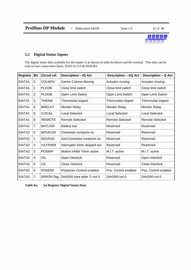
5.2 Digital Status Inputs The digital status data available for the master is as shown in table 6a below and 6b overleaf. This data can be read as four consecutive bytes, IDATA1/2/3 & DIAGR1.
Register Bit Circuit ref. Description – IQ Act Description – AQ Act Description – Q Act
IDATA1 0 COLMOV Centre Column Moving Actuator moving Actuator moving
IDATA1 1 PLCOB Close limit switch Close limit switch Close limit switch
IDATA1 2 PLOOB Open Limit Switch Open Limit Switch Open Limit Switch
IDATA1 3 THERM Thermostat tripped Thermostat tripped Thermostat tripped
IDATA1 4 MRELAY Monitor Relay Monitor Relay Monitor Relay
IDATA1 5 !LOCAL Local Selected Local Selected Local Selected
IDATA1 6 !REMOTE Remote Selected Remote Selected Remote Selected
IDATA1 7 BATLOW Battery low Reserved Reserved
IDATA2 0 MOVECW Clockwise contactor on Reserved Reserved
IDATA2 1 MOVEAC Anti-Clockwise contactor on Reserved Reserved
IDATA2 2 !VLFPWM Interrupter timer stopped act Reserved Reserved
IDATA2 3 POSMIF Motion Inhibit Timer active M.I.T. active M.I.T. active
IDATA2 4 OIL Open Interlock Reserved Open Interlock
IDATA2 5 CIL Close Interlock Reserved Close Interlock
IDATA2 6 POSENF Positioner Control enabled Pos. Control enabled Pos. Control enabled
IDATA2 7 ERROR flag DIAGR0 (see table 7) not 0 DIAGR0 not 0 DIAGR0 not 0
Table 6a: 1st Register Digital Status Data

Profibus DP Module - Publication S420E Issue 1.0 16 of 40
©
PROCESS FIELD BUS
N.B. IDATA3 is always 00 for AQ/Q actuators or IQ actuators with no remote board fitted. (See section 6 for parameterisation process description).
Register Bit Circuit ref. Description – IQ Act Description – AQ Act Description – Q Act
IDATA3 0 S1 Relay S1 status Reserved Reserved
IDATA3 1 S2 Relay S2 Status Reserved Reserved
IDATA3 2 S3 Relay S3 Status Reserved Reserved
IDATA3 3 S4 Relay S4 Status Reserved Reserved
IDATA3 4 !RMAIN2 Remote Maintain / Aux input 3 Reserved Reserved
IDATA3 5 !RCLOSE2 Remote Close / Aux input 2 Reserved Reserved
IDATA3 6 !ROPEN2 Remote Open / Aux input 1 Reserved Reserved
IDATA3 7 !TBPESD2 Remote ESD / Aux input 4 Reserved Reserved
DIAGR1 0 IFEDLG Datalogger interface (SK8) error, (IQ only)
Reserved Reserved
DIAGR1 1 IFEIOB Remote board interface (SK4,5,7) error, (IQ only)
Reserved Reserved
DIAGR1 2 MMRLYF Relay drive from Remote Module, (IQ only)
Reserved Reserved
DIAGR1 3 GOPOSF Positioner moving actuator Positioner moving actuator
Positioner moving actuator
DIAGR1 4 ESD485 RS485 ESD command received RS485 ESD command received
RS485 ESD command received
DIAGR1 5 AUXCTL AUX control input active, (IQ only)
Reserved Reserved
DIAGR1 6 CHAACT Channel 1 / 2 active Channel 1 / 2 active Channel 1 / 2 active
DIAGR1 7 CH2ACT Slave address enabled Slave address enabled Slave address enabled
Table 6b: 2nd Register Digital Status Data

Profibus DP Module - Publication S420E Issue 1.0 17 of 40
©
PROCESS FIELD BUS
5.2.1 Centre Column Moving –IQ / Actuator Moving on AQ & Q The actuator senses any movement of its centre column whether this is generated by a manual (hand) operation or by the action of the motor. Whenever the centre column is in motion this bit is set to a logic 1. 5.2.2 Close Limit Switch / Open Limit Switch There are two data bits relating to the actuator set positions for open and close positions. These limit positions may be set within the actual valve stroke. When a torque seating valve is closing, the actuator will stop when the seat is reached and the rated torque has been delivered, independent of the closed limit switch setting. The position limit switch must be set slightly before the torque off position so as to ensure that the position is correctly reported. The data relating to position is maintained even though the position itself has been passed through. When the actuator has reached the closed or open limit the respective bit will be set to a logic 1 5.2.3 Thermostat tripped The actuator motor is protected by a thermostat, if the temperature of the motor windings rises above the thermostat trip value, the thermostat contact will open and this bit will be set. There are no adjustments for the temperature at which the thermostat trip operates. The motor will be stopped if the thermostat trips. Only once the motor has cooled down and the thermostat has reset itself can a new Remote, Host or Local command to move the actuator Open or Closed be actioned. The ESD command may be set to override the thermostat. The bit will remain set at logic 1 until the motor cools down and the thermostat resets itself. 5.2.4 Monitor Relay The actuator includes a composite signal for some alarms referred to as the Monitor Relay. This bit will be set to logic 1 if the actuator selector is in Local or Local Stop (not in Remote) or if the thermostat trips. The actuator also monitors the main supply and if any phase is lost the monitor relay bit is set. Communications with the Module unit will then be lost if the actuator is single phase, or if the phase associated with the control circuits is lost on a three phase actuator. 5.2.5 Local Selected The actuator has a 3 position switch for selecting Remote, Local Stop or Local Control. The switch passes from Remote to Local, or Local to Remote, through the Local Stop position. When the actuator local control switch is fully in the Local position then this bit is set to logic 1. This data bit is not present when the actuator control switch is in the Local Stop or Remote positions. The bit is present as long as the switch is in the Local position and it will clear only when the switch is returned to the Remote or Local Stop position. 5.2.6 Remote Selected This data bit is similar to the Local selected bit in that when the actuator local control switch is fully in the Remote position then this bit is set to logic 1. This data bit is not present when the actuator control switch is in the Local Stop or Local Control positions. The bit is present as long as the switch is in the Remote position and it will clear only when the switch is returned to the Local Stop or Local Control position.

Profibus DP Module - Publication S420E Issue 1.0 18 of 40
©
PROCESS FIELD BUS
5.2.7 Battery Low - (only available on the IQ) The IQ actuator is fitted with a battery that is used to power the circuits used to keep track of the valve position when the actuator mains power is switched off. This battery is used only when the actuator has no power feed and the valve is actually moved. The condition of the battery is monitored at all times and a signal generated if the battery power is low. The Module reports the condition of the battery as a logic 1 when the battery voltage falls below a critical value. 5.2.8 Clockwise Contactor On / Anti-clockwise Contactor On - (only available on the IQ) There are two data bits relating to which one of the internal contactors is energised. If the contactor which causes the actuator to run in the clockwise direction is energized then “Clockwise Contactor On” is set to logic 1. Likewise if the contactor to run the actuator anti-clockwise is energized then “Anti-clockwise Contactor On will be set to logic 1. These signals will be reported whenever the contactor energises regardless of whether the command was issued from the host system, the local control knob or the remote pushbuttons that can be fitted. These signals provide indication only that a contactor is energised. Assuming that the actuator is functioning normally, the motor will also be running, however, these bits do not provide a true indication of this. Note: These signals provide no indication that the motor is rotating. 5.2.9 Interrupter Timer - (only available on the IQ) This feature gives automatic pulsed operation of a valve to reduce the effective speed of travel. The timer can be configured to operate over a percentage of travel in the opening and closing directions and the length of each ON and OFF pulse is configurable in the range 1 to 99 seconds using the setting tool. (Using a communicator, much wider timing range can be configured, i.e up to 4 ½ hours). If for example, the interrupter timer has been set and the actuator is travelling closed, during the periods when the actuator is not moving due to the interrupter timer, this bit will be set to logic 1. 5.2.10 MIT (Motion Inhibit Time) active Motion Inhibit Time is the time that the actuator inhibits motor operation, after it has stopped, in order to prevent the actuator exceeding its rated starts per hour. This bit is set after the positioner reaches the required position and has stopped. It stays active for the MIT time during which the positioner outputs are disabled. 5.2.11 Open / Close Interlocks- (only available on the IQ) Interlocks provide a means of inhibiting an actuator from opening or closing, even when commanded to do so, until a “safe to move” signal is applied via the interlock input, thus preventing an illegal valve movement. These two bits reflect the state of the interlock inputs and are only available if the Remote Input Board is fitted. When the interlock facility is enabled a hard wired signal needs to be applied to the correct terminal, in addition to the control signal, before the actuator moves in the required direction. The two interlock inputs also appear as Module input status bits, with the bit being set when the input is energised. If the interlock facility is turned off, the “interlock” signals can be used for reporting two additional digital general status inputs, via the Module, to the host system.

Profibus DP Module - Publication S420E Issue 1.0 19 of 40
©
PROCESS FIELD BUS
5.2.12 Position Control Enabled If the actuator is operating in positioning mode, this bit will be set. 5.2.13 Error, (DIAGR not 0) Upon detection of a Module fault this bit will be set. A diagnostic request is needed to determine the cause of this error. 5.2.14 S1 to S4 - (only available on the IQ) The logical four contacts S1 to S4 can be configured to make or break for one of the following functions, (see publication E170E - IQ Installation Instructions), and will be reported as logic 1 for made; - Closed limit - Open limit - Intermediate position indication - Torque trip in mid travel - Actuator closing - Actuator opening - Actuator output rotating - Motor stalled - Battery low - Hand operation - Blinker - Torque trip opening - Torque trip closing - Torque trip any position Note that the Actuator closing and opening signals give a true indication of actuator travel. The Clockwise and Anticlockwise contactor bits, (5.2.8), only indicate which contactor has been energized. (If only the clock and anticlockwise bits are used, knowledge of how the actuator has been set up is needed before actuator opening or closing can be determined). 5.2.15 AUX Inputs 1 to 4 - (only available on the IQ) The Auxiliary inputs may report as a logic 1 or 0 for the input contact being a closed circuit. The decision as to whether a 1 or 0 is reported is made by the setting of the relevant data bit in the invert mask, (settable with either the setting tool or communicator). Bits 0-3 relate to inputs AUX 1 - 4. If the bit in the mask is set to 0 then the data reported is a logic 0 when the contact source is closed, if the mask bit is set to 1 then a closed contact source is reported as a 1. The Auxiliary inputs may be also be used as a secondary control point for the actuator in which case they are designated as 'Remote Open', ' Stop/Maintain', 'Remote Close' and 'ESD' signals. In order to invoke the use of these signals as 'remote command inputs' the invert mask bits 4-7 must be set to '1' for the inputs being used. Note that by using both invert mask bit 0 and bit 4 set to '1' results in Aux 1 being used as a 'Remote Open' command - a closed contact causes the actuator to run open.

Profibus DP Module - Publication S420E Issue 1.0 20 of 40
©
PROCESS FIELD BUS
5.2.16 Datalogger Interface Error - (only available on the IQ) When there is an error with the Module to Datalogger interface, either Module SK8 or Datalogger SK2, or the associated loom, this bit will be set. 5.2.17 Remote Board Interface Error - (only available on the IQ) When there is an error with the Module to Remote Board interface, either Module SK5 & 4 to Remote Board SK2 or Module SK5 & 7 to Remote Board SK2, or the associated looms, this bit will be set. 5.2.18 Relay drive from the Remote Board - (only available on the IQ) This bit, when set, indicates that the output relays are being driven from external pushbuttons via the Remote Board. 5.2.19 Positioner moving actuator This bit, when set, indicates that the position controller is moving the actuator. 5.2.20 RS485 ESD command received If an ESD command has been received via RS485 highway, this bit will be set. 5.2.21 Aux control I/P active - (only available on the IQ) This bit, when set, indicates that an auxiliary input, (enabled for control), is active. 5.2.22 Channel 1 / 2 active This bit, when set = 1, indicates that the Module is communicating via channel 1. When = 0, communications is via channel 2. 5.2.23 Slave address enabled This bit, when set, indicates that the Module is able to be re-addressed.

Profibus DP Module - Publication S420E Issue 1.0 21 of 40
©
PROCESS FIELD BUS
5.3 Digital Diagnostic Inputs The digital diagnostic data available for the master is as shown in table 3. This data is transmitted in response to a diagnostics request. ( Bits 0 - 7 contain the data as shown in table 7). Along with this data, the version of software fitted in the COP processor is also returned. It comes as a set of ASCII characters in the form; “N”, “*”, “*”, “*”, where * * * indicates the version number. Comments; Bits 0 to 7 generate the “error” bit in the digital status register. Bit 0 - When set, indicates an EEPROM timeout has occurred. Bit 1 - When set, indicates that a checksum error has occurred with the settings of the address, loss of signal position and ProfFlags2. Bit 2 - When set, indicates that a checksum error has occurred with the settings of the motion inhibit time or deadband. Bit 3 - When set, indicates that a checksum error has occurred with the settings one or more of the following; minimum and maximum position, the optional digital input settings, the action on loss of signal and its associated time delay. When set, this bit will also inhibit control of the actuator. Bit 4 - This bit indicates whether the module has been reset after being powered on or has been reset by the watchdog. Bit 5 - The main board interface error indicates a problem with SK6 or its associated loom. Bit 6 - When set this indicates a problem with one of the connectors or looms on the Module. Bit 7 - Reserved
Register Bit Name Description
DIAGR0 0 EE_ERR EEPROM timeout error
DIAGR0 1 SM1ERRF Checksum number 1 error
DIAGR0 2 SM2ERRF Checksum number 2 error
DIAGR0 3 SM3ERRF Checksum number 3 error (control inhibit)
DIAGR0 4 WDOGRF Processor watchdog recovery
DIAGR0 5 IFEMNB Main Board interface (SK6) error
DIAGR0 6 SM4ERRF Checksum number 4 error
DIAGR0 7 Reserved
Table 7: Digital Diagnostic Data

Profibus DP Module - Publication S420E Issue 1.0 22 of 40
©
PROCESS FIELD BUS
5.4 Analogue Input Registers There are an additional four registers of analogue data that are sent from the slave to the master, (in addition to the three digital input registers). Bits 0 - 7 of register, TORQUE, POSITN & RAWPOS contain the data, bits 8 - 15 contain “00”.The TEMPER register contains a signed 16 bit integer value. 5.4.1 TORQUE - Torque Feedback - (only available on the IQ) Data relating to the current value of torque being developed by the actuator is available from the Module. Whilst the actuator motor is stationary this signal will remain as the last value measured. When the motor is running the signal will be in the range 0-120%, with a 1% resolution. There are no ranging adjustments required for the signal as it is pre-calibrated by the actuator settings, the signal is a percentage of rated actuator torque. On power up this will be set to 50% as no valid actuator torque will have been measured. The value sent from the Module to the Master will be in the range 0000 – 00FF hex. Where 00 corresponds to 0% and FF corresponds to 120%. The AQ and Q actuators will always return a value of 0000. 5.4.2 POSITN - Scaled Position Feedback – (available with all IQ’s and with positioning AQ and Q range actuators) The Profibus DP actuators always include an internal continuous valve position monitor. The data about the valve's position is fed to the Module for onward transmission as a Valve position feedback signal (0-100%) with a resolution of 1.0%. There are no ranging adjustments required for the signal as it is pre- calibrated by the limit switch settings of the actuator itself. Usually the actuator will be forward acting and the 0% value will correspond to the Close limit switch setting and 100% to the Open limit switch setting. In some cases the actuator itself may be configured so as to be reverse acting, 0% equal to fully open, under this configuration mode the Module will automatically modify its reported data to align with the revised setting of the actuator. The 0% reading will be returned when the actuator is Open. If the valve is torque seating then the torque off point position should be set very close to the limit switch setting so as to minimise the actual position error. Because of the actuator’s ability to scale itself over a range different from the end of travel positions, the value reported via this register may not be the same as the actuators true position. (see limited range position setting in section 5.5) The value sent from the Module to the Master will be in the range 0000 –00FF hex. Where 0000 corresponds to 0% and 00FF corresponds to 100%. When no limited range positioning is used, this will correspond to the actuator closed and open limits. However, when limited range positioning is used, 0000 corresponds to the lower limit and 00FF corresponds to the upper limit.
Register Description
TORQUE Calculated Torque
POSITN Scaled Position
RAWPOS Raw Position
TEMPER Temperature
Table 8: Analogue Input Registers

Profibus DP Module - Publication S420E Issue 1.0 23 of 40
©
PROCESS FIELD BUS
5.4.3 RAWPOS - Un-scaled Position Feedback – (available with all IQ’s and with positioning AQ and Q range actuators) Unlike POSITN which gives a position feedback scaled over the range configured in POSMIN and POSMAX, this register contains the true actuator position relative to its closed and open limits. The value sent from the Module to the Master will be in the range 0000 – 00FF hex. Where 00 corresponds to actuator closed and FF corresponds to actuator open 5.4.4 TEMPER - Actuator Internal Temperature This value relates to the temperature of the Module PCB in degrees centigrade. The value returned to the master is a signed, unscaled, 16 bit number as follows; 0000 - 0 °C 0001 to 7FFF - 1 to 32767 °C 8000 to FFFF - -32767 to –1 °C In reality, the temperature reading will never go outside the actuator temperature range.

Profibus DP Module - Publication S420E Issue 1.0 24 of 40
©
PROCESS FIELD BUS
5.5 Data Exchanged During Parameterisation There are various items that need to be set up during the parameterisation process. These need only to be set up once, but if there were a requirement to change them at a later date, the master can send an updated parameterisation telegram.
5.5.1 POSALS - Action on loss of signal This specifies what action the actuator will take after it has determined that there is no traffic on either of its highway inputs. The traffic on the highway has to be valid messages specifically addressed to the Module, otherwise, the timeout counter will decrement. Upon receipt of a valid message the counter resets to the value stored in DPSLTO. To determine a loss of signal, the Module scans the last port that was working, using all of the baud rates specified in the GSD file - see appendix. After a pre-determine timeout, (set in DPSLTO), it will then check its other port for traffic, again trying all baud rates. If it has no success, it will try the first port again. After following the above procedure, if the Module has been unable to detect any traffic, it will perform the action specified in this register. The action to be performed is determined by the value of bits 0 - 2, as shown in table 10. All other register bits are ignored. The default setting for this register is turn off action on loss of signal The default setting for this register is “OFF”, i.e. bit 0 = 0
Register Description
POSALS Action on loss of signal
POSMIN Limited range position - 0% position
POSMAX Limited range position - 100% position
POSDBD Positioner deadband
POSMIT Positioner motion inhibit timer
AUXMSK Auxiliary mask
LOSPOS Loss of signal position
DPSLTO Signal Loss Timeout
Table 9: Parameterisation Registers
Bit 15-3 Bit 2 Bit 1 Bit 0 Fuction
0 X X 0 Turn off action on loss of signal
0 X X 1 Turn on action on loss of signal
0 0 0 X Go to open limit
0 0 1 X Go to closed limit
0 1 0 X Stay put
0 1 1 X Go to position determined by LOSPOS reg-
Table 10: POSALS Register Contents (X = any value)

Profibus DP Module - Publication S420E Issue 1.0 25 of 40
©
PROCESS FIELD BUS
5.5.2 POSMIN / POSMAX - Limited range positioning, 0% position / 100% position It is possible to make the position data reported, (POSITN), relate to a reduced span of actual valve travel. In this mode the position data relates to a reduced portion of the valve stroke. This is sometimes used where the valve is required to have a 0% position (or 100% position) that is not the same as fully closed and fully open, (e.g. see fig 12 below). To make the actuator take note of limited range position reporting it is necessary to set the POSMIN and POSMAX to a value in the range 00 - FF, where 00 is the closed limit and FF is the open limit. Any position data reported will always be scaled over the range determined by POSMIN and POSMAX The default is always 100% reporting of position from the fully open to the fully closed limit positions, i.e. 0000 = closed limit, 00FF = open limit
5.5.3 POSDBD - Positioner Deadband The control algorithm used for the Module unit positioner is proportional only. The Module runs the actuator to the desired position then stops it and drops out of positioning mode. As the actuator and valve combination will have some inertia it is possible that the desired position may be 'overrun'. To prevent this from happening there is a Deadband setting whereby once the actuator enters the deadband the motor will be stopped. For example a 5% deadband will cause the motor to be stopped once the actual position is within 5% of the desired position. The inertia will then bring the actual position nearer to the desired position. It is important to set the deadband such that the actuator does not overrun the control point. 5.5.4 POSMIT - Positioner Motion Inhibit Timer The setting of the Motion Inhibit Timer is the period that must elapse between the actuator stopping and then restarting, during positioner mode operation. This idle period will prevent the actuator motor exceeding its rated starts per hour. The default value for this register is 05, corresponding to 5 seconds. 5.5.5 AUXMSK - Mask for Remote Auxiliary Control Inputs - (IQ option only) Provided the remote board is fitted, some or all of the four auxiliary input signals may be used as remote control inputs to operate the actuator. For the OPEN, CLOSE and STOP inputs to be actioned the actuator selector switch must be set in Remote, However, for ESD the actuator can be either in Local or Remote. The function of the four inputs are predefined when they are used as control inputs as shown overleaf. Note that a mixture of control inputs and data reporting inputs is acceptable. Control inputs are either maintained or momentary contact closures, depending on the setting of the STOP/MAINTAIN input, and the Module and actuator control circuit translates the input into a command to move the valve.
CLOSED OPEN
VALVE STROKE
0% 100%
Position-Minimum Setting Position-Maximum Setting
Reported Position
! !
Fig 12: Limited Range Position Reporting

Profibus DP Module - Publication S420E Issue 1.0 26 of 40
©
PROCESS FIELD BUS
AUX 1 - REMOTE OPEN AUX 2 - REMOTE CLOSE AUX 3 - REMOTE STOP/MAINTAIN AUX 4 - EMERGENCY SHUT DOWN The Auxiliary Input Configuration Mask must be enabled for the desired function to be set into the actuator. When this is suitably set the Remote Auxiliary Inputs will be Remote Auxiliary Control inputs. These controls override any existing host system command or Position control action except for a host system ESD command. The 8 data bits in the mask relate to the function and contact sense of the inputs. The 4 most significant bits relate to the use of the inputs for actuator control, if a '1' is put in the mask in the appropriate position the that input is enabled as an actuator control input, if a '0' is placed in the mask then the input becomes a reported signal only. The 4 least significant bits relate to the sense of the input. A '1' placed in the appropriate bit makes a contact closure achieve the action or be reported as a '1' on the data communications. A '0' placed in the bit inverts the signal and makes a contact opening achieve the action or be reported as a '1', (see table 11).
AUX 1 Bit 0 0 Report closed contact input as ‘0’, action as control input if enabled
1 Report closed contact input as ‘1’, action as control input if enabled
AUX 2 Bit 1 0 Report closed contact input as ‘0’, action as control input if enabled
1 Report closed contact input as ‘1’, action as control input if enabled
AUX 3 Bit 2 0 Report closed contact input as ‘0’, action as control input if enabled
1 Report closed contact input as ‘1’, action as control input if enabled
AUX 4 Bit 3 0 Report closed contact input as ‘0’, action as control input if enabled
1 Report closed contact input as ‘1’, action as control input if enabled
AUX 1 Bit 4 0 Disable AUX 1 as ‘OPEN’ command
1 Enable AUX 1 as ‘OPEN’ command
AUX 2 Bit 5 0 Disable AUX 2 as ‘CLOSE’ command
1 Enable AUX 2 as ‘CLOSE’ command
AUX 3 Bit 6 0 Disable AUX 3 as ‘STOP/MAINTAIN’ input, all remote inputs always push to run mode
1 Enable AUX 3 as ‘STOP/MAINTAIN’ command
AUX 4 Bit 7 0 Disable AUX 4 as ‘ESD’ command
1 Enable AUX 4 as ‘ESD’ command
Table 11: Auxiliary Mask Settings

Profibus DP Module - Publication S420E Issue 1.0 27 of 40
©
PROCESS FIELD BUS
The auxiliary input mask takes the form as shown in table 12:
Example 1
Example 2
Example 3 Key: Enable = 1 to enable the input as a Remote Control Input. Invert = 1 for a normally open input contact to achieve this action. Example 1: Remote auxiliary control ESD input contact, opening to cause an ESD, with the actuator set to be push to run, (no connection need be made to the AUX 3, (Stop/Maintain), input). Example 2: Remote auxiliary control ESD input contact input, opening to cause ESD, remote Open and Close inputs where a closing contact causes the actuator motion, all motion to be “push to run” mode. Example 3: Remote auxiliary control ESD input contact , closing to cause ESD, remote Open and Close inputs where a closing contact causes the actuator motion, all motion in “push to run” mode, AUX 3 input utilised for a contact input that reports its state over the RS485 highway, when the AUX 3 contact is closed a ‘1’ is reported. The default setting for this register is 0F, (hex) 5.5.4 LOSPOS - Loss of signal position If POSALS has been set to position, on loss of signal, i.e. bits 1 & 2 = 11, then this register determines the position that the actuator will be sent to. Values in the range 0000 = 0% and 00FF = 100% are permitted. However, if limited range positioning is used, the LOSPOS value will also be scaled by the same factor. The default value for this register is 00 5.5.5 DPSLTO - Signal Loss Timeout The number in this register, is the length of time, in seconds, that the Module will wait before it determines that there is no valid messages for itself on its RS485 port. The default value for this register is 00FF, (hex) = 255 seconds
MSB LSB
Bit 7 Bit 6 Bit 5 Bit 4 Bit 3 Bit 2 Bit 1 Bit 0
Enable AUX 4 (ESD)
Enable AUX 3 (Stop/ Maintain)
Enable AUX 2 (CLOSE)
Enable AUX 1 (OPEN)
Invert AUX 4
Invert AUX 3
Invert AUX 2
Invert AUX 1
1 1 0 0 0 1 X X
1 0 1 1 0 X 1 1
1 0 1 1 1 1 1 1
Table 12: Auxiliary Mask Examples

Profibus DP Module - Publication S420E Issue 1.0 28 of 40
©
PROCESS FIELD BUS
5.6 Data Exchanged During Configuration The configuration data sets up the amount of data that is transferred during the data exchange process. The length of the user data sent between the master and the slave is the same irrespective of what type of Rotork actuator the Module is fitted to. The config data can contain an extra variable containing flags to confirm what options are fitted. Table 13 shows the user information available during the configuration process.
Description Flag Default
IQ Actuator 0 = yes 1 = no
0, yes
Datalogger Fitted 0 = no 1 = yes
0, no
Table 13: User Data Flags

Profibus DP Module - Publication S420E Issue 1.0 29 of 40
©
PROCESS FIELD BUS
6. PROFIBUS DP MODULE POWER-UP PROCESS On power-up the Module monitors a communications channel, looking for a baud rate. As there are two channels to communicate over, the first channel tested is the one saved in variable ProfFlags2, extracted from the EEPROM on power up. If communications are not established after a set period of time, DPSLTO, the other channel is tested. If communications are not established here, the Module tries the first channel again. Finally, if communications are not established after the set period of time the action on loss of signal, if enabled, is actioned. The value of the variable POSALS determines whether the action is enabled and what action is to be taken. The choice of actions are Stayput, Open, Close or the position set up in variable LOSPOS. The state machine for the start-up process is shown below in figure 13 Power On All Rotork Profibus DP Modules are supplied configured to a default address of 126 - unless an address is specified at the time of ordering. This address may only be used for commissioning purposes, i.e. it cannot be used to exchange user data. Only in the power on state can the Module accept a “set-slave-address” telegram from a class 2 master, to enable it to change it’s address. The Module then stores the address in its EEPROM. (If the module is mounted in an IQ actuator the address can be configured by using a Rotork IQ Setting Tool or by using a Rotork Communicator, via the infra red link).
Configuration OK
Parameterisation OK
Power on
Wait forParameterisation
Wait forConfiguration
Data Exchange
Check config notOK
Set param notOK
Check data
Check data
Figure 13: The state machine of a Profibus DP slave
Set slave address

Profibus DP Module - Publication S420E Issue 1.0 30 of 40
©
PROCESS FIELD BUS
Wait for Parameterisation Details of the complete telegram for parameters can be found in EN50170 After a channel has been selected and a baud rate negotiated (the bus will run at the highest speed of the slowest device) the Module will wait for a parameterisation telegram from the Master. Whilst waiting the Module rejects all other types of telegram. The telegram contains the user information shown in table 14, which sets up a number of variables required for actuator operation. The default values will be sent if no change is required. The response from the Module to a parameterisation telegram is E5, (hex). It will not report a parameterisation error until the master issues a request for diagnostic data that is correctly accepted. For an explanation of the register contents see section 5.5
Wait for Configuration The next telegram expected from the master is configuration, which sets up what data is exchanged in the data exchange mode. The Module checks that this telegram is as expected. The Rotork Slave receives three 16 bit registers of data from the master and will reply with seven 16 bit registers of data, therefore the configuration telegram will contain the following data:
ConfSpId - special identifier to indicate user data included in the telegram ConfOp - value required for six bytes of output data, (three registers) ConfUs - User data, default value = 00, i.e. fitted to an IQ actuator. (see table 13) ConfIp - value required for 12 bytes of data, (six registers) Acknowledgement of the configuration telegram is “E5” (hex). If the Module discovers discrepancies when it compares the information with the GSD file, it will discard the configuration data and report the incorrect configuration to the master when asked for diagnostics later. The slave is then no longer ready for user data communication. After the satisfactory acceptance of both the Parameter and Configuration telegrams the slave and master enter a data exchange mode, where data is cyclically transferred between master and Slave. The data transferred is described in sections 5.1 to 5.4.
1st byte sent
RESERVED POSALS POSMIN POSMAX POSDBD POSMIT AUXMSK LOSPOS
User data sent from master to Module in Parameterisation telegram
Last byte sent
DPSLTO
Table 14 - User Parameter data
User data sent from master to Module in Configuration telegram
1st byte sent Last byte sent
ConfSpId = 81 (hex) ConfOp = 05 (hex) ConfIp = 1B (hex) ConfUs = 00
Table 15 - User Configuration data

Profibus DP Module - Publication S420E Issue 1.0 31 of 40
©
PROCESS FIELD BUS
7 CHANGEABLE VARIABLES Table 16 shows the variables that can be changed within the Profibus DP Module, and what can be used to change them. The AQ and Q actuator variables can only be modified by a DP master.
Notes: DP Master = These settings can be altered by the DP master. C = IQ Communicator S = IQ Setting Tool - The settings that can be set using the setting tool require the use of the Pakscan and Folomatic menus, see the IQ Installation manual, E170E.
Variable Name
Description Range Default Changeable using
IQ Setting tool menu
POSALS
Positioner action on loss of signal.
Bit 0 – On / Off Bit 1 & 2 – 00 = Hi 01 = LOW 10 = SP 11 = Position
off DP Master IQ - C, S
FF / FA
POSMIN Positioner minimum position (scaled)
00 - FF hex, (C,DP) 0 - 100, (S) (0-100%)
00 (0%)
DP Master IQ - C, S
FL
POSMAX Positioner maximum position (scaled)
00 - FF hex, (C,DP) 0 - 100, (S) (0-100%)
FF hex 100 (100%)
DP Master IQ - C, S
FH
POSDBD See 7.1
Positioner deadband 00 – FF hex (0 - 9.9% S, 0 - 25.5% C,DP)
32 hex (5%)
DP Master IQ - C,S
FD
POSMIT Positioner motion in-hibit time
00 – FF hex (0 – 255s)
5 DP Master IQ - C,S
FT
AUXMSK Auxiliary input con-figuration mask
00 – FF hex 0F DP Master IQ - C,S
PF
LOSPOS Action on loss of sig-nal position
00 - FF hex (0%-100%)
00 DP Master IQ - C
DPSLTO Signal Loss Timeout 00 - FF hex (0 - 255 s)
FF hex 255 secs
DP Master IQ - C
ACTCON Actuator Control Reg-ister
N/A DP Master IQ - C
POS_DV Positioner position re-quired
00 - FF (0-100%)
N/A DP Master IQ - C
O_STAT Relay status under bits 0-3 set pattern. DP Master
ProfFlags2 See 7.2
Status flags - 03 (hex) IQ - C,S PB
Table 16 - Changeable variables

Profibus DP Module - Publication S420E Issue 1.0 32 of 40
©
PROCESS FIELD BUS
7.1 Positioner Deadband Using the IQ Setting Tool, the positioner deadband can only be set from 0 to 9.9%. This is due to the IQ setting menu that it uses. Using the Profibus and IQ Communicator the deadband can be set from 0 - 25.5%, but a deadband higher than 9.9% will show as “??” when scrolling through the IQ setting menu. 7.2 ProfFlags2 The IQ Setting Tool menu, “PB” is the baud rate menu for Pakscan. The Profibus DP module uses this menu for displaying to the user which channel the Module is transmitting over, and whether the master has been granted permission to change the Module address. See table 17 for details of the register bits.
Setting Tool “PB” Display
Module address change
Communicating on channel?
ProfFlags2 value
01 Disabled 2 0
03 Disabled 1 1
06 Enabled 2 2
12 Enabled 1 3
Table 17 - ProfFlags2 Options

Profibus DP Module - Publication S420E Issue 1.0 33 of 40
©
PROCESS FIELD BUS
8.0 PROGRAMMING A PROFIBUS DP MODULE WITH A SETTING TOOL This section relates to a Profibus DP Module that is fitted in an IQ actuator. (Configuration of an AQ or Q actuator can only be done via a master). This section outlines the steps needed to programme the parameters listed below using an IQ Setting Tool. Note that the Setting Tool can only be used to programme the Module when the actuator selector knob is set to the local control position. To change any of the following parameters it is essential for the actuator to be in “setting mode” rather than “viewing mode”. (For further information on setting up an IQ actuator see the IQ Installation Instructions Manual E170E). - Address - ProfFlags2 setting - Auxiliary Input Mask - (available only when a remote board is fitted). - Minimum Position - Maximum Position - Motion Inhibit Timer - MIT Deadband - Action on loss of RS485 signal The above options are all available via the “secondary function settings” within the setting tool options menus.
Figure 14: Secondary Function Settings

Profibus DP Module - Publication S420E Issue 1.0 34 of 40
©
PROCESS FIELD BUS
Address / ProfFlags2 / Auxiliary Mask These options are all programmable via the Pakscan option menu, however, from a safety point of view, it is advisable to change these parameters only when the master is not connected. Using the menu on the previous page select the Pakscan option [OP], and set it to “[on ]”. Address change The address is able to be changed in the [PA ] screen which is reached by pressing the down arrow. Using the “+” and “-” keys allows the address to be changed. Once the correct address has been selected, press enter. The display will blink to confirm that it has received and accepted the new setting, unless address changes have been disabled bby ProfFlags2. ProfFlags2 change The ProfFlags2 setting is able to be changed in the [PB ] screen which is reached by pressing the across arrow . Using the “+” and “-” keys allows the value to be changed between, 01, 03, 06 and 12 - see table 17 for details). Once the correct setting has been selected, press enter. The display will blink to confirm that it has received and accepted the new setting. Auxiliary input mask change The auxiliary input mask is able to be changed in the [PF ] screen which is reached by pressing the across arrow . Using the “+” and “-” keys allows the mask to be changed. Once the correct mask has been selected, press enter. The display will blink to confirm that it has received and accepted the new setting.
Minimum Position / Maximum Position / Motion Inhibit Timer / MIT Deadband / Action on loss of RS485 signal These options are all programmable via the Folomatic option menu. Using the menu on page 46 select the Folomatic option [OF ] and set it to “[on ]”. The first item that needs to be checked is the Folomatic feedback setting. Press the across arrow until the [0I ] screen is reached. The display should be set to [HI ], indicating that 0% is displayed as 0% and 100% is displayed as 100%. (If the display is set to [LO ] the Modbus positioning function will not operate). Minimum position change Press the down arrow to reach the Folomatic set up displays and then the across arrow until the [FL ] screen is reached. This allows the minimum position to be entered, “[ ][ ]“ = valve closed, “[ = = ]” = valve open and “[01 ]” to “[99 ]” = percent open. Select the correct value and press enter, the display will blink to confirm that it has received and accepted the new setting. Maximum position change Press the across arrow once and the [FH ] screen will appear. This allows the maximum position to be entered, (similar to the minimum position above). Select the correct value and press enter, the display will blink to confirm that it has received and accepted the new setting.
[OP ] [on ] down arrow! [PA ] across [PB ] across [PF ] [01 ] arrow [96 ] arrow [FF ]
Figure 15: Setting Menus for baud rate, address and auxiliary mask

Profibus DP Module - Publication S420E Issue 1.0 35 of 40
©
PROCESS FIELD BUS
MIT deadband change Press the across arrow once and the [fd ] screen will appear. Use the “+” or “-” key to select the deadband from 00 to FF, corresponding to 0% to 25.5% of setpoint signal. Select the correct value and press enter, the display will blink to confirm that it has received and accepted the new setting. MIT change Press the across arrow once and the [ft ] screen will appear. Use the “+” or “-” key to select the deadband from 00 to 99, corresponding to 0 to 99 seconds. Select the correct value and press enter, the display will blink to confirm that it has received and accepted the new setting. Action on loss of RS485 signal There are two screens to be checked when setting this function. Press the across arrow once and the [FA ] screen will appear. If the actuator is to go to go to a set position or to stay put on detection of a loss of RS485 signal, set the value to [on ] using the + or - key. If a loss of signal is to have no effect on the actuator then the option [of ] should be selected, using the + or - key. Once the correct value has been chosen press enter and the display will blink to confirm that it has received and accepted the new setting. If [on ] has been chosen, press the across arrow once and the [ff ] screen will appear. Using the + or - key select either [lo ], which will send the actuator to the 0% set point, or [sp ] which will cause the actuator to stop where it is, or [hi ] which will cause the actuator to move to the 100% position. Once the correct value has been chosen press enter and the display will blink to confirm that it has received and accepted the new setting. Using the Setting Toool, it is not possible to set the positioner value to any value other than open or closed. If the Module has been set to a position by the Communicator, for example, the IQ will display “??”, when it reaches this screen.
Figure 16: Setting Menus for Minimum Position, Maximum Position, Motion Inhibit Timer, MIT Deadband and Action on loss of RS485 signal [0F] across [0l] [0N ] arrow [Hl] down arrow [fl ] across [fh ] across [fd] across [ft] across [FA ] across [FF ] [ ] [ ] arrow [==] arrow [50 ] arrow [50 ] arrow [ 0F] arrow [L0 ]

Profibus DP Module - Publication S420E Issue 1.0 36 of 40
©
PROCESS FIELD BUS
9. MAINTENANCE AND REPAIR There is no periodic service requirement for the Module. Repairs should not be attempted on the Module. Any failure should be rectified by replacing the Module with new compatible device. Static sensitive and CMOS devices are used in the Module. It is therefore mandatory to observe anti-static precautions when handling or working on a Module. The Module may be stored for a period of up to 10 years in clean conditions.

Profibus DP Module - Publication S420E Issue 1.0 37 of 40
©
PROCESS FIELD BUS
GSD file for Rotork Profibus DP Module ; GSD file for Rotork Profibus DP module - Version 1 ; ; October 1998 ; ; For a detailed description of the Rotork ProfiBus DP module see ; Rotork Document S420E - ProfiBus DP Module Technical Manual ; #Profibus_DP ; Vendor_Name = "Rotork Controls Ltd" Model_Name = "Actuator DP Interface" Revision = "1.01" Ident_Number = 0x073A Protocol_Ident = 0 Station_Type = 0 FMS_supp = 0 Hardware_Release = "42580/82-**" Software_Release = "N1**" ; ; Supported Transmission rates ; 9.6_supp = 1 93.75_supp = 1 187.5_supp = 1 19.2_supp = 1 500_supp = 1 1.5M_supp = 1 12M_supp = 0 MaxTsdr_9.6 = 60 MaxTsdr_19.2 = 60 MaxTsdr_93.75 = 60 MaxTsdr_187.5 = 60 MaxTsdr_500 = 100 MaxTsdr_1.5M = 150 MaxTsdr_12M = 800 ; ; Slave Information ; Redundancy = 1 Repeater_Ctrl_Sig = 1 24V_Pins = 0 Freeze_Mode_supp = 1 Sync_Mode_supp = 1 Auto_Baud_supp = 1 Set_Slave_Add_supp = 1 User_Prm_Data_Len = 9 ; ; Parameter data: ; Special byte for SPC3, POSALS, POSMIN, POSMAX, POSDBD, POSMIT, AUXMSK, LOSPOS, DPSLTO User_Prm_Data = 0x00, 0x00, 0x00, 0xFF, 0x32, 0x05, 0x0F, 0x00, 0xFF Min_Slave_Intervall = 1 Modular_Station = 0 Max_Module = 2 Max_Input_Len = 12 ;12 bytes of data slave to master Max_Output_Len = 6 ;6 bytes of data master to slave Max_Diag_Data_Len = 12 ;5 bytes of User diagnostics ; ; Module Information ; Module = "IQ module" 0x81, 0x05, 0x00, 0x1b ;12 Inputs, 6 Outputs EndModule Module = "AQ/Q module" 0x81, 0x05, 0x01, 0x1b ;12 Inputs, 6 Outputs EndModule

Profibus DP Module - Publication S420E Issue 1.0 38 of 40
©
PROCESS FIELD BUS

Profibus DP Module - Publication S420E Issue 1.0 39 of 40
©
PROCESS FIELD BUS

Profibus DP Module - Publication S420E Issue 1.0 40 of 40
©
PROCESS FIELD BUS
Rotork Controls Ltd Rotork Controls Inc Bath, England 19, Jet View Drive BA1 3JQ Rochester tel: (01225) 733200 New York 14624 fax: (01225) 333467 USA http://www.rotork.com tel: (716) 328 1550 [email protected] fax: (716) 328 5848