PSZ 19:16 (Pind. 1/07) UNIVERSITI TEKNOLOGI...
25
PSZ 19:16 (Pind. 1/07) DECLARATION OF THESIS / UNDERGRADUATE PROJECT PAPER AND COPYRIGHT Author’s full name : MOHAMMAD JOSHANI Date of birth : 19 JANUARY 1981 Title : NONLINEAR FINITE ELEMENT ANALYSIS OF STEEL-CONCRETE COMPOSITE SLABS USING EXPLICIT DYNAMICS PROCEDURE Academic Session : 2009/2010 - 2 I declare that this project report is classified as: I acknowledged that Universiti Teknologi Malaysia reserves the right as follows: 1. The thesis is the property of Universiti Teknologi Malaysia. 2. The Library of Universiti Teknologi Malaysia has the right to make copies for the purpose of research only. 3. The Library has the right to make copies of the project report for academic exchange. SIGNATURE (NEW IC NO. / PASSPORT NO.) NAME OF SUPERVISOR Date: 28 MARCH 2010 Date: 14 APRIL 2010 NOTES : * If the thesis is CONFIDENTIAL or RESTRICTED, please attach with the letter from the organisation with period and reasons for confidentiality or restriction. UNIVERSITI TEKNOLOGI MALAYSIA √ CONFIDENTIAL (Contains confidential information under the Official Secret Act 1972)* RESTRICTED (Contains restricted information as specified by the organization where research was done)* OPEN ACCESS I agree that my thesis to be published as online open access (full text) A12205237 DR. REDZUAN ABDULLAH Certified by: SIGNATURE OF SUPERVISOR
Transcript of PSZ 19:16 (Pind. 1/07) UNIVERSITI TEKNOLOGI...

PSZ 19:16 (Pind. 1/07)
DECLARATION OF THESIS / UNDERGRADUATE PROJECT PAPER AND COPYRIGHT
Author’s full name : MOHAMMAD JOSHANI Date of birth : 19 JANUARY 1981 Title : NONLINEAR FINITE ELEMENT ANALYSIS OF STEEL-CONCRETE COMPOSITE SLABS USING EXPLICIT DYNAMICS PROCEDURE Academic Session : 2009/2010 - 2 I declare that this project report is classified as: I acknowledged that Universiti Teknologi Malaysia reserves the right as follows:
1. The thesis is the property of Universiti Teknologi Malaysia. 2. The Library of Universiti Teknologi Malaysia has the right to make copies for the purpose
of research only. 3. The Library has the right to make copies of the project report for academic exchange.
SIGNATURE (NEW IC NO. / PASSPORT NO.) NAME OF SUPERVISOR
Date: 28 MARCH 2010 Date: 14 APRIL 2010
NOTES : * If the thesis is CONFIDENTIAL or RESTRICTED, please attach with the letter from the organisation with period and reasons for confidentiality or restriction.
UNIVERSITI TEKNOLOGI MALAYSIA
√
CONFIDENTIAL (Contains confidential information under the Official Secret Act 1972)*
RESTRICTED (Contains restricted information as specified by the organization where research was done)*
OPEN ACCESS I agree that my thesis to be published as online open access (full text)
A12205237 DR. REDZUAN ABDULLAH
Certified by:
SIGNATURE OF SUPERVISOR

Fakulti Kejuruteraan Awam
Universiti Teknologi Malaysia
PENGESAHAN PENYEDIAAN SALINAN E-THESIS
…………………………………...………………………..................................................
.............................................................................................................................................
Ijazah : .........................................................................................
Fakulti : ......................................................................................
Sesi pengajian : ......................................................................................
Saya ....................................................................................................................................
(HURUF BESAR)
No Kad Pengenalan .................................... mengaku telah menyediakan salinan e-thesis
sama seperti tesis asal yang telah diluluskan oleh panel pemeriksa dan mengikut
panduan penyediaan Tesis dan Disertasi Elektronik (TDE), Sekolah Pengajian
Siswazah, Universiti Teknologi Malaysia, March 2010.
................................................................. .........................................................
(Tandatangan pelajar) (Tandatangan penyelia sebagai saksi)
Alamat tetap:
................................................................... Penyelia: ...................................................
...................................................................
................................................................... Fakulti: ......................................................
...................................................................
Tarikh: ...................................................... Tarikh: ....................................................
Judul tesis:
UTM(FKA)-1/02
A12205237
MOHAMMAD JOSHANI
Master of Engineering (Civil – Structure)
Fakulti Kejuruteraan Awam
2009/2010
DR. REDZUAN ABDULLAH
Fakulti Kejuruteraan Awam
NONLINEAR FINITE ELEMENT ANALYSIS OF STEEL-CONCRETE
COMPOSITE SLABS USING EXPLICIT DYNAMICS PROCEDURE
Nota: Borang ini yang telah dilengkapi hendaklah dikemukakan kepada FKA bersama penyerahan CD.
28 MARCH 2010 14 APRIL 2010

“I hereby declare that I have read this project report and in my opinion
this report is sufficient in terms of scope and quality for the award of
the degree of Master of Engineering (Civil – Structure).”
Signature : _________________________
Name of Supervisor : DR. REDZUAN ABDULLAH
Date : _____14 APRIL 2010_______

NONLINEAR FINITE ELEMENT ANALYSIS OF STEEL-CONCRETE
COMPOSITE SLABS USING EXPLICIT DYNAMICS PROCEDURE
MOHAMMAD JOSHANI
A project report submitted in partial fulfillment of the
requirements for the award of the degree of
Master of Engineering (Civil-Structure)
Faculty of Civil Engineering
Universiti Teknologi Malaysia
APRIL 2010

ii
I declare that this project report entitled “Nonlinear Finite Element Analysis of Steel-
Concrete Composite Slabs using Explicit Dynamics Procedure” is the result of my own
research except as cited in the references. This project has not been accepted for any
degree and is not concurrently submitted in candidature of any other degree.
Signature : _____________________
Name of Writer : MOHAMMAD JOSHANI
Date : ____28 MARCH 2010 _

iii
TO MY BELOVED MOTHER AND FATHER
FOR THEIR ENDLESS LOVE AND SUPPORT
iv
ACKNOWLEDGEMENT
First and foremost, I would like to express my sincerest gratitude and
appreciation to my supervisor, Dr. Redzuan Abdullah for his worthwhile guidance
throughout this project. His wide knowledge and his expert advice during the period I
have been carrying out this research, has been of great value for me. His invaluable
comments, kind consideration, encouragement and supports have provided a good basis
for the present thesis.
The author would like to express his deepest gratitude to his parents for their
support and encouragement and for working so hard to give him a good education.

v
ABSTRACT
Composite slab construction using permanent cold-formed steel decking has
become one of the most economical and industrialized forms of flooring systems in
modern building structures. Structural performance of the composite slab is affected
directly by the horizontal shear bond phenomenon at steel-concrete interface layer.
This study utilizes 3D nonlinear finite element quasi-static analysis technique
through explicit dynamics procedure to analyze the shear bond damage and fracture
mechanics of the composite slabs. Cracking of the plain concrete over the
corrugated steel deck has been modeled considering the mixed modes fracture
mechanisms by means of concrete damaged plasticity model available in ABAQUS
software version 6.9. The interface layer damage was simulated with cohesive
elements presented in ABAQUS software considering three modes of fracture.
Cohesive fractures properties such as fracture energy and initiation stress have been
derived from horizontal shear stress versus end slip curves which were extracted
from bending test of a series of small scale specimens. The proposed model is
verified through comparison with experimental data which demonstrated that the
results of the numerical analyses match with valid experimental results. Therefore
these calibrated and validated models can predict the structural response of steel-
concrete composite slabs. This will reduce the cost of empirical works which in
accordance with present design specifications are mandatory in order to investigate
the behavior and load bearing capacity of such structural systems.

vi
ABSTRAK
Pembinaan papak rencam dengan menggunakan deck keluli terbentuk sejuk yang
kekal merupakan salah satu jenis sistem papak yang paling ekonomi bagi struktur
bangunan moden. Prestasi struktur bagi papak rencam dipengaruhi secara langsung
oleh fenomena ikatan ricih mengufuk di antara muka keluli dan konkrit. Dalam
kajian ini, analisis ‘quasi-static’ unsur terhingga 3D yang menggunakan prosedur
‘explicit dynamics’ telah dijalankan bagi menilai kerosakan ikatan ricih mengufuk
dan mekanik retakan pada papak rencam. Retakan pada konkrit di atas dek keluli
beralun telah dimodelkan dengan mengambil kira mekanik retakan dengan mod
tergabung. Model kemusnahan plastic yang terdapat dalam perisian ABAQUS telah
diguna dengan mengambil kira tiga mode retakan. Kemusnahan pada antara muka
keluli dan konkrit telah dimodel dengan unsur ‘cohesive’. Sifat retakan ‘cohesive’
seperti tenaga retakan dan tegasan pemula telah diterbitkan daripada geraf tegasan
ricih mengufuk lawan gelangsaran hujung yang diambil daripada ujian lenturan
bersaiz kecil. Model analisis yang dicadangkan dalam kajian ini disahkan
kejituannya dengan mebuat perbandingan antara hasil analisis dengan data ujikaji.
Hasilnya, model analisis ini boleh diguna untuk menilai gerak balas struktur papak
rencam. Hal ini boleh mengurangkan kerja ujikaji yang dahulunya mesti dilakukan
untuk menentukan kelakuan sebenar dan kebolehtanggungan beban system papak
rencam.

vii
TABLE OF CONTENTS
CHAPTER TITLE PAGE
DECLARATION ii
DEDICATION iii
ACKNOWLEDGEMENT iv
ABSTRACT v
ABSTRAK vi
TABLE OF CONTENTS vii
LIST OF TABLES x
LIST OF FIGURES xi
LIST OF APPENDICES xx
NOMENCLATURES xxi
I INTRODUCTION 1
1.1 Introduction to Steel-Concrete Composite Slabs 1
1.2 Problem Statement 8
1.3 Aim of Study 10
1.4 Objectives of Study 10
1.5 Scopes of Study 11
1.6 Organization and Outline of Thesis 12
II LITERATURE REVIEW 13
2.1 Introduction 13
2.2 Fracture Mechanics and NFEA 14

viii
2.2.1 Fracture Modes 16
2.2.2 Composite Slab Behavior with Respect
to Fracture Mechanics
17
2.3 Simulation of Composite Slabs 19
2.4 Explicit Dynamics Procedure 21
2.5 Introduction to Cohesive Fracture Theory 22
2.5.1 Concept of Cohesive Zone Model 24
2.5.2 Inter-layer Damage Modeling using
Cohesive Element
26
2.5.3 Cohesive Elements and Insertion
Algorithms
26
2.5.4 Cohesive Element Formulation
2.5.5 Traction Separation Law, TSL
28
30
2.5.6 Interfacial Material Properties 31
2.5.7 Interface Debonding Initiation and
Propagation
32
2.5.7.1 Constitutive Equations for
Interface Damage
32
2.5.7.2 Mixed-mode Debonding
Criterion
34
2.5.7.3 Damage Evolution Law
Implementation
36
2.6 Damaged Plasticity Model for Concrete 42
2.6.1 Post-failure Stress-Strain Relation 46
2.6.2 Fracture Energy Cracking Criterion 47
2.6.3 Defining Compressive Behavior
48
III METHODOLOGY 50
3.1 Introduction 50
3.2 Development of the FE model 51
ix
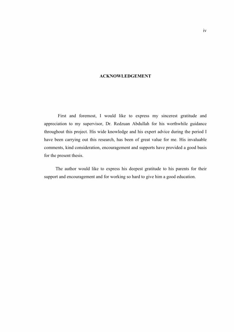
3.2.1 Models geometry and characterization 51
3.2.2 Finite Element Mesh Generation 57
3.2.3 Concrete Properties Definition 60
3.2.4 Steel Properties Definition 64
3.2.5 Interface Layer Properties Definition 65
3.2.6 Boundary Conditions 68
IV RESULTS AND DISCUSSION 70
4.1 Introduction 70
4.2 Case A (3VL16-4-7.5 composite Slab) 73
4.3 Case B (3VL16-8-7.5 composite Slab) 91
4.4 Case C (3VL16-10-7.5 composite Slab) 107
4.5 Case D (3VL16-12-5 composite Slab) 117
4.6 Case E (3VL16-14-5 composite Slab) 128
V CONCLUSIONS & RECOMMENDATIONS 141
5.1 Conclusions 141
5.2 Recommendations 144
REFERENCES 145
BIBLIOGRAPHY 150
Appendices A - B
159-
164
x
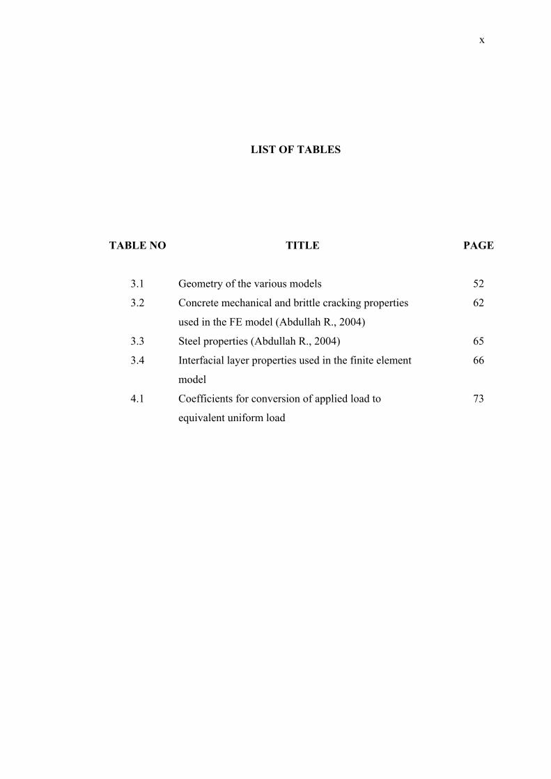
LIST OF TABLES
TABLE NO TITLE PAGE
3.1 Geometry of the various models 52
3.2 Concrete mechanical and brittle cracking properties
used in the FE model (Abdullah R., 2004)
62
3.3 Steel properties (Abdullah R., 2004) 65
3.4 Interfacial layer properties used in the finite element
model
66
4.1 Coefficients for conversion of applied load to
equivalent uniform load
73

xi
LIST OF FIGURES
FIGURE NO TITLE PAGE
1.1 Configuration of a typical steel-concrete composite
slab with trapezoidal decking.
2
1.2 Illustration of an open rib type of composite slab. 2
1.3 Typical Trapezoidal and Re-entrant deck profiles. 4
1.4 Examples of trapezoidal deck profiles: (Left side) Up
to 60 mm deep; (Right side) Greater than 60 mm
deep
5
1.5 Typical forms of interlock in composite slabs 7
2.1 Visualization of general modes of fracture 17
2.2 Steel-concrete composite slab collapse modes. 18
2.3 Application of cohesive zone elements along bulk
element boundaries
23
2.4 Cohesive stresses are related to the crack opening
width (w).
25
2.5 Variation of cohesive stress with respect to the crack
opening displacement in the process zone.
26
2.6 Stress distribution and cohesive crack growth in
mode-I opening for concrete.
29
2.7 Forms of the TSL: a) cubic, b) constant, c)
Exponential, d) Tri-linear
30
2.8 Debonding damage model 31
2.9 Constitutive strain softening equations 32

xii
2.10 (a) Visualization of the process zone at the crack tip,
and definition of displacement jump δ and cohesive
tractions t. (b) Example of mode I cohesive law:
Rose-Smith-Ferrante universal binding law.
34
2.11 Power law form of the shear retention model. 36
2.12 Mode mix measures based on traction 38
2.13 Linear damage evolution. 39
2.14 Illustration of mixed-mode response in cohesive
elements.
40
2.15 Fracture energy as a function of mode mix. 41
2.16 Tensile stress-elongation curves for quasi-brittle
material.
43
2.17 FPZ in Quasi-brittle (concrete). 43
2.18 Response of concrete to uniaxial load in tension (a)
and compression (b).
44
2.19 Illustration of the definition of the cracking strain
used for the definition of tension stiffening data.
46
2.20 Post-failure stress-displacement curve. 47
2.21 Fracture energy illustration. 48
2.22 Definition of the compressive inelastic (or crushing)
strain used for the definition of compression
hardening data.
49
3.1 Geometry of beam corresponding to 3VL16-4-7.5
composite slab.
53
3.2 a) Isometric view of test setup b) Details at supports 54
3.3 Small Scale specimens before concrete casting 55
3.4 Pour stop at the end section of small scale beams 55
3.5 Configuration of the small scale test setup 56
3.6 Picture of a full-scale composite slab specimen 56
3.7 Schematic view of composite slab with trapezoidal
decking (VULCRAFT)
57
3.8 Mesh pattern for 3VL16-4-7.5 composite deck slab 57
3.9 Mesh pattern for 3VL16-8-7.5 composite deck slab 58
xiii
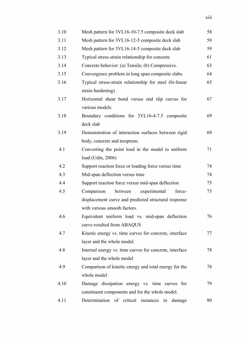
3.10 Mesh pattern for 3VL16-10-7.5 composite deck slab 58
3.11 Mesh pattern for 3VL16-12-5 composite deck slab 59
3.12 Mesh pattern for 3VL16-14-5 composite deck slab 59
3.13 Typical stress-strain relationship for concrete 61
3.14 Concrete behavior: (a) Tensile; (b) Compressive. 63
3.15 Convergence problem in long span composite slabs. 64
3.16 Typical stress-strain relationship for steel (bi-linear
strain hardening)
65
3.17 Horizontal shear bond versus end slip curves for
various models
67
3.18 Boundary conditions for 3VL16-4-7.5 composite
deck slab
69
3.19 Demonstration of interaction surfaces between rigid
body, concrete and neoprene.
69
4.1 Converting the point load in the model to uniform
load (Udin, 2006)
71
4.2 Support reaction force or loading force versus time 74
4.3 Mid-span deflection versus time 74
4.4 Support reaction force versus mid-span deflection 75
4.5 Comparison between experimental force-
displacement curve and predicted structural response
with various smooth factors.
75
4.6 Equivalent uniform load vs. mid-span deflection
curve resulted from ABAQUS
76
4.7 Kinetic energy vs. time curves for concrete, interface
layer and the whole model.
77
4.8 Internal energy vs. time curves for concrete, interface
layer and the whole model
78
4.9 Comparison of kinetic energy and total energy for the
whole model
78
4.10 Damage dissipation energy vs. time curves for
constituent components and for the whole model.
79
4.11 Determination of critical instances in damage 80

xiv
evolution process of 3VL16-4-7.5 composite slab
4.12 Damage status in the concrete and in the cohesive
interface layer when the mid-span displacement is
equal to 2.3mm.
82
4.13 Exhibition of crack development paths in the right
side of the small scale beam tested at Virginia Tech
(Abdullah, 2004).
82
4.14 Damage status in the concrete and in the cohesive
interface layer when the mid-span displacement is
equal to 4.9 mm.
83
4.15 Damage status in the concrete and in the cohesive
interface layer when the mid-span displacement is
equal to 10 mm.
85
4.16 Exhibition of major crack due to slip failure in the
left side of the small scale beam tested at Virginia
Tech (Abdullah, 2004)
85
4.17 Illustration of Major crack due to slip failure at the
right side of the small scale specimen tested at
Virginia Tech (Abdullah, 2004)
86
4.18 Depiction of longitudinal end slip resulted from
analysis with ABAQUS
86
4.19 Von Mises stress contour in whole of the specimen
when time is equal to 0.03 second
87
4.20 (Second picture) Contour of longitudinal shear bond
stress along the length of the composite slab when the
damage status in the interface layer is exhibited with
the first upper picture.
88
4.21 Longitudinal Shear stress vs. time for six random
elements as shown in previous figure.
89
4.22 Variation of end slip according to time for 3VL16-4-
7.5 composite slab.
89
4.23 Longitudinal Shear bond stress vs. end slip 90
4.24 Contour of displacement in direction 2 for 3VL16-4- 90

xv
7.5 composite slab with scale factor allocated equal
by 3.
4.25 Picture of end slip for 3VL16-4-7.5 composite slab
(Abdullah, 2004)
91
4.26 Support reaction force or applied loading force versus
time curve.
92
4.27 Mid-span deflection versus time indicating loading
rate.
93
4.28 Support reaction force or applied loading force versus
mid-span deflection.
93
4.29 Comparison between experimental force-
displacement curve and predicted structural response
94
4.30 Kinetic energy vs. time curves for concrete, interface
layer and the whole model.
94
4.31 Internal energy vs. time curves for concrete, interface
layer and the whole model.
95
4.32 Comparison of kinetic energy and total energy for the whole model.
96
4.33 Damage dissipation energy vs. time curves for
constituent components and for the whole model.
96
4.34 Steps of Damage in Concrete and Interface according
to equivalent uniform load graph.
98
4.35 Damage status in the concrete and in the cohesive
interface when the mid-span displacement is equal to
8.5 mm.
99
4.36 Crack maps for specimen 3VL16-8-7.5 (Abdullah,
2004)
100
4.37 Exhibition of crack development paths in the left side
of the small scale beam tested at Virginia Tech
(Abdullah, 2004)
101
4.38 Damage status in the concrete and in the cohesive
interface when the mid-span displacement is equal to
24 mm.
102
4.39 Picture of longitudinal displacement of the model 103

xvi
which shows that the red color region near the bottom
flange has slipped and displaced to left
4.40 Von Mises stress contour in whole of the specimen at
a certain time.
104
4.41 (Second picture) Contour of longitudinal shear bond
stress along the length of the composite slab.
105
4.42 Longitudinal Shear stress vs. time for some random
elements as shown in previous figure.
105
4.43 Horizontal shear stress versus end slip 106
4.44 Picture of end slip of 3VL16-8-7.5 composite slab 106
4.45 Contour of displacement in direction 2 for steel
decking of 3VL16-8-7.5 composite slab with scale
factor
107
4.46 Buckling shape of steel decking at final stages of
loading tested at Virginia Tech (Abdullah, 2004).
107
4.47 Support reaction force versus time graph. 108
4.48 Mid-span deflection versus time indicating loading
rate.
109
4.49 Support reaction force versus mid-span deflection
graph.
109
4.50 Comparison between experimental force-
displacement curve and predicted structural response
110
4.51 Kinetic energy vs. time curves for concrete, interface
layer and the whole model.
110
4.52 Internal energy vs. time curves for concrete, interface
layer and the whole model.
111
4.53 Comparison of kinetic energy and total energy for the
whole model.
112
4.54 Damage dissipation energy vs. time curves for
concrete, interface layer and the whole model.
112
4.55 Steps of Damage in Concrete and Interface according
to applied uniform load vs. mid-span deflection
graph.
113

xvii
4.56 Damage status in the concrete and in the cohesive
interface when the mid-span displacement is equal to
12 mm.
114
4.57 Picture of longitudinal displacement of the model. 115
4.58 Von Mises stress contour in whole of the specimen at
a certain time step.
115
4.59 Longitudinal Shear stress vs. time for some random
elements at interface layer.
116
4.60 Longitudinal Shear bond stress vs. end slip curve. 116
4.61 Configuration of test set-up for 3VL16-12-5
Composite Slab
117
4.62 Mid-span deflection versus time indicating loading
rate.
117
4.63 Support reaction force versus mid-span deflection
graph.
118
4.64 Equivalent uniform load vs. mid-span deflection
curve resulted from ABAQUS in comparison with
experimental tests.
118
4.65 Kinetic energy vs. time curves for concrete, interface
layer and the whole model.
119
4.66 Internal energy vs. time curves for concrete, interface
layer and the whole model.
120
4.67 Comparison of kinetic energy and total energy for the
whole model.
121
4.68 Damage dissipation energy vs. time curves for
concrete, interface layer and the whole model.
121
4.69 Steps of Damage in Concrete and Interface according
to equivalent uniform load graph.
122
4.70 Damage status in the concrete and in the cohesive
interface when the mid-span displacement is equal to
33 mm.
123
4.71 Picture of crack development paths in the concrete
body
124
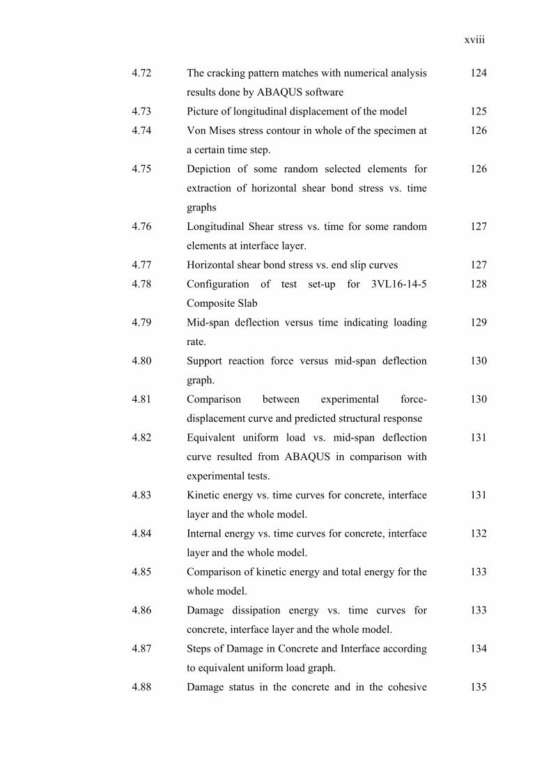
xviii
4.72 The cracking pattern matches with numerical analysis
results done by ABAQUS software
124
4.73 Picture of longitudinal displacement of the model 125
4.74 Von Mises stress contour in whole of the specimen at
a certain time step.
126
4.75 Depiction of some random selected elements for
extraction of horizontal shear bond stress vs. time
graphs
126
4.76 Longitudinal Shear stress vs. time for some random
elements at interface layer.
127
4.77 Horizontal shear bond stress vs. end slip curves 127
4.78 Configuration of test set-up for 3VL16-14-5
Composite Slab
128
4.79 Mid-span deflection versus time indicating loading
rate.
129
4.80 Support reaction force versus mid-span deflection
graph.
130
4.81 Comparison between experimental force-
displacement curve and predicted structural response
130
4.82 Equivalent uniform load vs. mid-span deflection
curve resulted from ABAQUS in comparison with
experimental tests.
131
4.83 Kinetic energy vs. time curves for concrete, interface
layer and the whole model.
131
4.84 Internal energy vs. time curves for concrete, interface
layer and the whole model.
132
4.85 Comparison of kinetic energy and total energy for the
whole model.
133
4.86 Damage dissipation energy vs. time curves for
concrete, interface layer and the whole model.
133
4.87 Steps of Damage in Concrete and Interface according
to equivalent uniform load graph.
134
4.88 Damage status in the concrete and in the cohesive 135

xix
interface when the mid-span displacement is equal to
40 mm.
4.89 Cracks developed in the laboratorial test of 3VL16-
14-5 Composite Slab
136
4.90 Crack maps for specimen 3VL16-14-5 composite slab
136
4.91 Picture of longitudinal displacement of the model. 137
4.92 Von Mises stress contour in whole of the specimen
when mid-span deflection is equal to 4cm.
138
4.93 Depiction of some random selected elements for
extraction of horizontal shear bond stress vs. time
graphs.
138
4.94 Longitudinal Shear stress vs. time for some random
elements at interface layer.
139
4.95 Longitudinal Shear bond stress vs. end slip curve. 139
4.96 Picture of end slip for 3VL16-14-5 composite slab
(Abdullah, 2004)
140

xx
LIST OF APPENDICES
APPENDIX TITLE PAGE
A Mixed mode fracture 159
B Comparison between experimental results and
numerical results with various smooth factors for
various composite slabs.
161

xxi
NOMENCLATURES
b Unit width of slab
d Midspan displacement
dd Depth of profiled steel deck
ds Steel deck depth
E Modulus of elasticity / Young’s modulus
E11 Modulus of elasticity in longitudinl direction
E22 Modulus of elasticity in transverse direction (2-axis)
E33 Modulus of elasticity in transverse direction(3-axis)
Ec Modulus of elasticity of concrete
Es Modulus of elasticity of steel deck
f′c Concrete compressive strength
Fy Minimum yield strength of steel sheeting
Fu Ultimate strength of steel sheeting
G12 Stiffness modulus in plane 1-2
G13 Stiffness modulus in plane 1-3
G23 Stiffness modulus in plane 2-3
hc Concrete cover depth above deck top flange
ht Total slab thickness
L Total slab span
Ls Shear span
M Bending moment
P Point load
t Steel sheeting thickness
tc Concrete thickness

xxii
U1 Movement in axis 1
U2 Movement in axis 2
U3 Movement in axis 3
UR1 Rotation movement in axis 1
UR2 Rotation movement in axis 2
UR3 Rotation movement in axis 3
w Uniform load
υ Poisson’s ratio
δ Vertical deflection
τ Shear bond stress