
PS1550 Brochure GB
12
FAULT TOLERANT POWER SUPPLIES FAULT TOLERANT POWER SUPPLIES FOR MISSION CRITICAL APPLICATIONS PROCESS AUTOMATION
description
ps 1550
Transcript of PS1550 Brochure GB

FAULT TOLERANT POWER SUPPLIESFAULT TOLERANT POWER SUPPLIESFOR MISSION CRITICAL APPLICATIONS
PROCESS AUTOMATION

PROCESS AUTOMATION
Company Presentation 3
PS1550 System Overview 4-5
Mission Critical Power Supply 6
PS1550 Terminations Option and Block Diagram 7
PS1550 Technical Specifications 8
Ordering Information and Dimensions 9
KFA6-STR-1.24.500 10
KFA6-STR-1.24.4 11

COMPANY PRESENTATION
Now that Pepperl+Fuchs has built up a world-leading position with end users andcontrol system manufacturers for conventional interface devices for intrinsicallysafe explosion protection, we are using these established sales paths for newproduct families.
Confirming our strong tradition of power supply manufacturer, this brochuredescribes our high integrity 24 V power supply for powering intrinsic safetycabinets, field instrumentation and conditioning systems. The power supplysystem PS1550 is particularly suitable for critical applications such as EmergencyShutdown and Fire & Gas protection systems.
Finally, the recently acquired display and operating terminal (HMI) from the EXTECbrand will enable us to enter the field of diagnosis and configuration platforms forfield bus technology, whilst our level control products cover the field devicerequirements to round off our overall strategy.
Our target industries are involved in chemicals and pharmaceuticals, petrochemicals, and other areas involving waste water treatment and power technology. In all industrial areas Pepperl+Fuchs is both a supplier and partner for endusers, control system manufacturers, system integrators and engineering contractors.
Your pathway to precision and performanceThe Process Automation division of the Pepperl+Fuchs Group, of whichPepperl+Fuchs Elcon is a 100% daughter company, is today the undisputedmarket leader in all three World markets – America, Europe and Asia – when itcomes to components for intrinsically safe explosion protection.

4
PS1550 System Overview
Fault Tolerant
Both the ac supply and 24 Vdc output can beconfigured with redundant n+1 modules formission critical applications.
Full Alarm Monitoring
All critical functions are automaticallymonitored and indicated by LED’s and alarmrelay outputs.
Hot Swappable ModulesAll modules are hot swappable on-line,ensuring your 24 Vdc is available at all times.
High Power Output!
Up to 36 Amps @ 24 Vdc is
available and all modules load share and automatically
adjust to the load.

5
Front Panel Test Jacks
Output modules include LED indicators and testjacks for current and voltage output calibration.
Choice of Mounting
19” Rack with front or rear flanges formounting.
Tagging
Provided on the front of every module.
Integral Cooling FansThree cooling fans with LED indicators are monitored by the internal alarm system.

6
Mission Critical Power Supply
PS 1550 System
A 4U High 19” rack mounting system, with integral cooling fans, a choice of 3 alternate plug-in output termination modules, 2 Supply (1550/LM) Line Modules and up to 6 (1550/PM) Power Modules.
Each Power Module provides 6 Amps at 24 Vdc.
Using 2 Line Modules and a n+1 Power Module strategy, the PS 1550 provides a unique mission critical capability.
High Output With Full Redundancy
� Maximum output of 36 Amps at 24 Vdc nominal per rack using six 1550/PM Power Modules.
� Fully redundant configuration provides 30 Amps at 24 Vdc, with n+1 (1550/PM) Power Module and two (1550/LM)Line Module failure strategy.
� With a fully redundant strategy the system is tolerant to theloss of 1 Supply Line and 1 Line Module or one or more PowerModules.
� Load sharing across all Power Modules ensures that the load is supplied evenly on failure of a Power Module withautomatic adjustment to the present load.
� Mixed AC/DC input capability permits battery back-up without the need for a UPS.
� Unlike current fold back designs the PS 1550 supplies fulloutput (60 Amps total) in a short circuit, instantly clearing afaulty fuse to avoid voltage spikes affecting other units on thesame supply bus.
Self Monitoring � Under permanent ( > 10 sec.) overload, the output is
automatically disconnected to prevent a cable fire.
A short pulse transmitted every 10 seconds will restart theoutput automatically when the fault is removed, to avoid on-site manual restart procedures.
Integral Alarm Monitoring
� All critical functions are automatically monitored andindicated by LEDs and relay outputs.
� Output integrity is maintained even in the event of loss of:
- Supply line.
- Line Module.
- Power Module.
- Cooling fan module.
� Alarm monitoring provides a contact ouput for:
- Low voltage on supply lines.
- Low voltage on output bus.
- Power Module overload, with LED indication.
- Power Module low output.
- Power Module internal fault.
- Power Module temperature limit protection, to prevent destructive failures.
- Failure of one of the three integral fans, LEDs indicate which fan has failed.
� Two relay outputs are provided for users to set and/or alarmfunctions.
Hot Swappable Plug-in Modules
� Modular load sharing design including “Hot Swappable”modules with self detection and signalling of faults,minimizes servicing and maximises MTTR (Mean Time ToRepair).
� Easy upgraded while on-line, by plugging in extra PowerModules.

PS1550 Terminations Option and Block Diagram
7
Input and Optional Output Terminations
� Plug-in termination options. 1550/TB-IN is mandatory, select a 1550/TB-OUT option to suit your output termination requirements.
1550/TB-IN AC input terminationmodule, for dual independently isolatedpower inputs and alarm outputs.
1550/TB-OUT Output termination modulewith 16 pairs of 2.5mm2,4 Amp rated terminals.
1550/TB-OUT 4/20 Optionaloutput termination module, with 4 pairs of 6 mm2, 20 Amp rated terminals.
1550/TB-OUT 60 Optional output terminationmodule, provides 1 pair of 60 Amp rated terminals.
Power Module# 5
FAN 1OK
LINE 1 ON
AC/DCSUPPLYLINE 2
AlarmContacts# 1
LINE FILTERS
INPUT/ALARMTERMINATION
MODULE
ALARM
ALARMOUT ON
OVERLOAD
OUT ON
OVERLOAD
OUT ON
OVERLOAD
OUT ON
OVERLOADFaultOutput
LINE VOLTAGE BUS
OUTPUT BUS
Power Module# 1
Power Module# 2
Power Module# 6
Line Module # 1
Line Module # 2(Redundant)
AlarmContacts# 2
AC/DCSUPPLYLINE 1
+
24 VdcOUT
OUTPUTTERMINATION
MODULE
1550/TB-OUT
1
16
1
16
(# 3 / # 4)
ISOLATEDFROMEACHOTHER
+24 V
0 V
FAN FAULT DETECTION
FAN 2OK
FAN 3OK
1550/LM
1550/LM
1550/TB-IN
1550/PM 1550/PM 1550/PM 1550/PM
LINE 2 ON
+
24 Vdc OUT
OPTION OUTPUTTERMINATION
MODULE
1550/TB-OUT4/20
1
4
1
4
+24 V
0 V
+
24 Vdc OUT
OPTION OUTPUTTERMINATION
MODULE
1550/TB-OUT60
1
1
+24 V
0 V
OUTPUT TERMINAL OPTIONS
~~
~~LoadSharing
POWER ON
POWER ON
PS1550 - Block Diagram
Order Information
8
PS1550 Technical Specifications
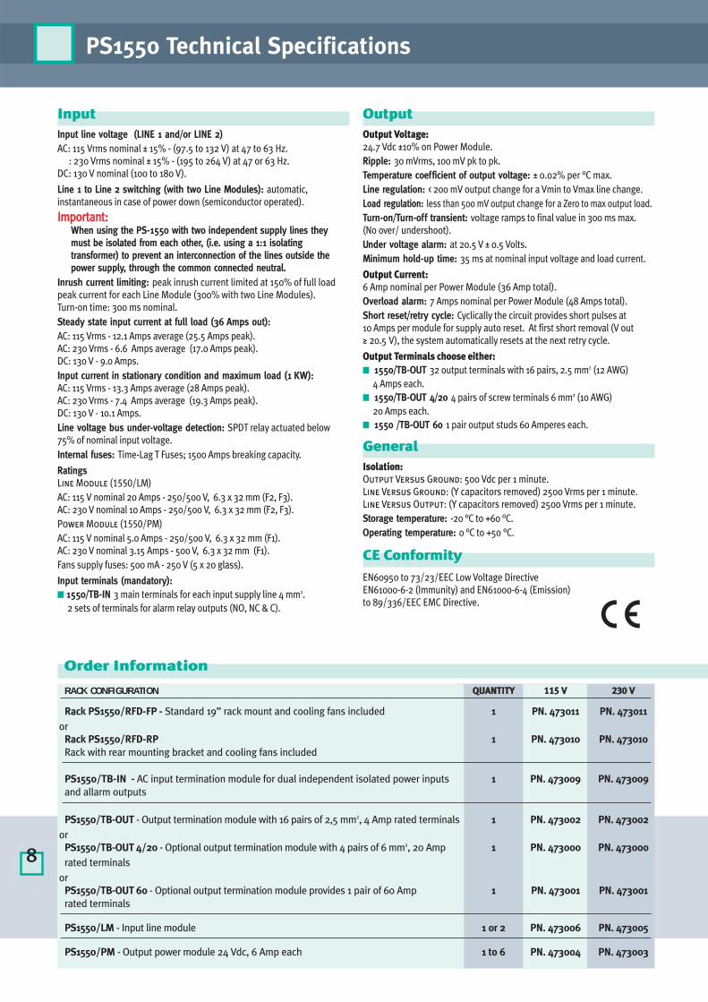
InputInput line voltage (LINE 1 and/or LINE 2)AC: 115 Vrms nominal ± 15% - (97.5 to 132 V) at 47 to 63 Hz.
: 230 Vrms nominal ± 15% - (195 to 264 V) at 47 or 63 Hz.DC: 130 V nominal (100 to 180 V).
Line 1 to Line 2 switching (with two Line Modules): automatic,instantaneous in case of power down (semiconductor operated).
IImmppoorrttaanntt:: When using the PS-1550 with two independent supply lines theymust be isolated from each other, (i.e. using a 1:1 isolatingtransformer) to prevent an interconnection of the lines outside thepower supply, through the common connected neutral.
Inrush current limiting: peak inrush current limited at 150% of full loadpeak current for each Line Module (300% with two Line Modules). Turn-on time: 300 ms nominal.Steady state input current at full load (36 Amps out): AC: 115 Vrms - 12.1 Amps average (25.5 Amps peak).AC: 230 Vrms - 6.6 Amps average (17.0 Amps peak).DC: 130 V - 9.0 Amps. Input current in stationary condition and maximum load (1 KW): AC: 115 Vrms - 13.3 Amps average (28 Amps peak).AC: 230 Vrms - 7.4 Amps average (19.3 Amps peak).DC: 130 V - 10.1 Amps.Line voltage bus under-voltage detection: SPDT relay actuated below75% of nominal input voltage.Internal fuses: Time-Lag T Fuses; 1500 Amps breaking capacity.
Ratings Line Module (1550/LM)AC: 115 V nominal 20 Amps - 250/500 V, 6.3 x 32 mm (F2, F3).AC: 230 V nominal 10 Amps - 250/500 V, 6.3 x 32 mm (F2, F3).Power Module (1550/PM)AC: 115 V nominal 5.0 Amps - 250/500 V, 6.3 x 32 mm (F1).AC: 230 V nominal 3.15 Amps - 500 V, 6.3 x 32 mm (F1).Fans supply fuses: 500 mA - 250 V (5 x 20 glass).
Input terminals (mandatory): � 1550/TB-IN 3 main terminals for each input supply line 4 mm2.
2 sets of terminals for alarm relay outputs (NO, NC & C).
OutputOutput Voltage:24.7 Vdc ±10% on Power Module.Ripple: 30 mVrms, 100 mV pk to pk.Temperature coefficient of output voltage: ± 0.02% per °C max.Line regulation: < 200 mV output change for a Vmin to Vmax line change.Load regulation: less than 500 mV output change for a Zero to max output load.Turn-on/Turn-off transient: voltage ramps to final value in 300 ms max. (No over/ undershoot).Under voltage alarm: at 20.5 V ± 0.5 Volts.Minimum hold-up time: 35 ms at nominal input voltage and load current.
Output Current: 6 Amp nominal per Power Module (36 Amp total). Overload alarm: 7 Amps nominal per Power Module (48 Amps total).Short reset/retry cycle: Cyclically the circuit provides short pulses at10 Amps per module for supply auto reset. At first short removal (V out≥ 20.5 V), the system automatically resets at the next retry cycle.
Output Terminals choose either: � 1550/TB-OUT 32 output terminals with 16 pairs, 2.5 mm2 (12 AWG)
4 Amps each. � 1550/TB-OUT 4/20 4 pairs of screw terminals 6 mm2 (10 AWG)
20 Amps each. � 1550 /TB-OUT 60 1 pair output studs 60 Amperes each.
GeneralIsolation:Output Versus Ground: 500 Vdc per 1 minute.Line Versus Ground: (Y capacitors removed) 2500 Vrms per 1 minute.Line Versus Output: (Y capacitors removed) 2500 Vrms per 1 minute.Storage temperature: -20 °C to +60 °C.Operating temperature: 0 °C to +50 °C.
CE Conformity
EN60950 to 73/23/EEC Low Voltage Directive EN61000-6-2 (Immunity) and EN61000-6-4 (Emission) to 89/336/EEC EMC Directive.
RACK CONFIGURATION QQUUAANNTTIITTYY 111155 VV 223300 VV
Rack PS1550/RFD-FP - Standard 19” rack mount and cooling fans included 1 PN. 473011 PN. 473011or
Rack PS1550/RFD-RP 1 PN. 473010 PN. 473010Rack with rear mounting bracket and cooling fans included
PS1550/TB-IN - AC input termination module for dual independent isolated power inputs 1 PN. 473009 PN. 473009and allarm outputs
PS1550/TB-OUT - Output termination module with 16 pairs of 2,5 mm2, 4 Amp rated terminals 1 PN. 473002 PN. 473002or
PS1550/TB-OUT 4/20 - Optional output termination module with 4 pairs of 6 mm2, 20 Amp 1 PN. 473000 PN. 473000rated terminals
orPS1550/TB-OUT 60 - Optional output termination module provides 1 pair of 60 Amp 1 PN. 473001 PN. 473001rated terminals
PS1550/LM - Input line module 1 or 2 PN. 473006 PN. 473005
PS1550/PM - Output power module 24 Vdc, 6 Amp each 1 to 6 PN. 473004 PN. 473003

9
Ordering Information and Dimensions
��������
Typical Example
PS1550 Dimensions: mm (inches)

� 230 V AC / 115 V AC mains nominalvoltage.
� 24 V DC output voltage. � Max. output current 500 mA.� No ground connection required.� Removable terminal and Power rail.
Order information: Part Number 046544.
PS Range -KFA6-STR-1.24.500 - DIN Rail Power Supply
10
ApplicationThe DIN Rail power supply, for small applications, is fully compatible withK-System Power Rail.The output voltage of the power supply is regulated and remains stableregardless of the power supply size and the load current.
Specification
Power Suppy
Connection Type: Terminals 14, 15.
Rated Operational voltage Ue: 90 … 253 V AC, 48 … 63 Hz.
Output
Connection Type: Power Rail or terminals 7 (+), 8 (-).
Voltage: 24 V ± 0.5 V.
Current: 500 mA at 60 °C, permanent short-circuit protection (electronically).
Galvanic Isolation
Power supply/Output: safe isolation acc. to DIN VDE 0106, designisolation voltage 253 Veff.
Ambient Conditions
Ambient temperature: -20 … 60 °C (253 … 333 K).
Mechanical specifications
Weight: approximate 140 g.
KFA6-STR-1.24.500 replaces type STR300 and KFA*-STR-1.26.600.
KFA6-STR-1.24.500KFA6-STR-1.24.500
Green LED: Power supply
Removable Terminals
Power Supply
Output Power rail
green
14 15
7 (+) 8 (-)
+ -
Module Dimensional Drawing
20 115
100
Schematic

� UL approval.� 230 V AC / 115 V AC mains nominal
voltage.� Output current max. 4 A.� Output voltage on: green LED.� Error message: flashing red LED.� Removable terminals and Power Rail.
Order information: Part Number 054270.
11
PS Range -KFA6-STR-1.24.4 - DIN Rail Power Supply
KFA6-STR-1.24.4KFA6-STR-1.24.4
Fuse carrier
green LED
indicates
output
voltage,
flashing red
indicates
that a fault
exists
Output
Power supply
Power rail
L1
4(-) 6(-)
2 13
N
4 AT
Dimensional Drawing
Primary Secondary
PE L1 N + -
103.
5
14088
99
14088
99
DeratingPower output
Ambienttemperature
%100
60 70˚C
75
Current limit characteristics
Outputcurrent
automatic re-start
4.6 A
V
24
16
Schematic
ApplicationUniversal input DIN Rail power supply for medium sized applications. The output voltage of the supply is fully regulated and remains stable tosatisfy the required load. This supply is fully compatible with our K-Systempower rail, DIN rail powering system.
Specification
Power SupplyConnection type: Terminals 2 (L1), 3 (N).Rated operational voltage Ue: 92 … 265 V AC, 47 … 63 Hz.Rated operational current: 1.2 A at 230 V AC.Contact loading: 230 V AC / < 30 A / cosj = 0.6 … 0.5 capacitive proximitysensors.Failure override time: > 75 ms / 230 V AC; 5 ms / 115 V AC.
OutputConnection type: Terminals 4 (+), 6 (-).Voltage: 23.28 … 24.72 V DC.Current: 0 ... 4 A, Power Rail limiting by means of fuse 4 AT, Typ. 4.6 A.Ripple: < 100 mVss.Efficiency: typ. 87 %. Overvoltage protected: < 28 V DC.
Galvanic IsolationPower supply / Output: For AC 253 V design isolation voltage.
Ambient ConditionsAmbient temperature: -20 … 60 °C (253 … 333 K).
Mechanical SpecificationsWeight: Approximate 800 g.Construction type: Housing 140 x 88 x 103.5 mm.Mounting: Clamping element for snap-mounting on top hat rail as perDIN EN 50022-35.Connection: Connection possibilities self-opening instrument terminals,max. conductor csa 2 x 2.5 mm2.
Electromagnetic compatibilitySafety: Accord. to VDE 0805 / EN 60 950.Radio-interference supression: Accord. to VDE 0875 part 11, EN 55 011class B.Electrostatic discharge: Accord. to IEC 801-2.Contact discharging: 8 kV.Air discharging: 15 kV.Electromagnetic fields: Accord. to IEC 801-3, 10 V/m.Burst IEC - Input: 4 kV; output/capacitively coupled: 2 kV.Surge IEC 801-5 - Asymmetrical: L, N -> PE 4 kV; symmetrical: L -> N 2 kV.

PROCESS AUTOMATION – PROTECTING YOUR PROCESSFor half a century, Pepperl+Fuchs have been continually providing new stimuli for the world of automation. The company is alsosetting standards in quality and innovative technology. We develop, produce and distribute electronic sensors and interfacemodules on a global scale. By means of our world-wide presence and our high flexibility in production and customer servicewe are able to individually offer complete solutions – right where you need us. We know what we are talking about –Pepperl+Fuchs have established a good reputation in supplying the world’s biggest offer of industrial sensor technology for alarge scale of applications. Our signals move the world.
Mannheim
Twinsburg
Singapore
www.pepperl-fuchs.com
Subject to reasonable modifications due to technical advances • Copyright PEPPERL+FUCHS ELCON • Printed in Italy • Part. No. 475208 06/06 04
Worldwide HeadquartersPepperl+Fuchs GmbH68307 Mannheim · GermanyTel. +49 621776-0e-mail: [email protected]
USA HeadquartersPepperl+Fuchs Inc. · 1600 Enterprise ParkwayTwinsburg, Ohio 44087 · USATel. +1 330 4253555 · Fax +1 330 4254607e-mail: [email protected]
Asia pacific HeadquartersPepperl+Fuchs Pte Ltd. · P+F Building18 Ayer Rajah Crescent · Singapore 139942Company Registration No. 199003130ETel. +65 67799091 · Fax +65 68731637e-mail: [email protected]
South and East Europe HeadquartersPepperl+Fuchs Elcon Srlvia delle Arti e Mestieri, 4 - 20050 Sulbiate (Mi) · ItalyTel. ++39 039 6292 1 · Fax ++39 039 6292 240e-mail: [email protected]