Proses Manufaktur II - · PDF fileProses Manufaktur II ... Milling a sculptured surface with...
47
Mesin Milling Proses Manufaktur II Sumber: Manufacturing Engineering and Technology Oleh: Serope Kalpakjian
Transcript of Proses Manufaktur II - · PDF fileProses Manufaktur II ... Milling a sculptured surface with...

Mesin Milling Proses Manufaktur II
Sumber: Manufacturing Engineering and Technology Oleh: Serope Kalpakjian

2
Proses dengan
Mesin Milling
Mesin milling merupakan mesin perkakas dengan mata potong banyak (multi points tools),
Jenis mesin milling: horizontal milling & vertical milling.
Vertical milling
Horizontal milling

3
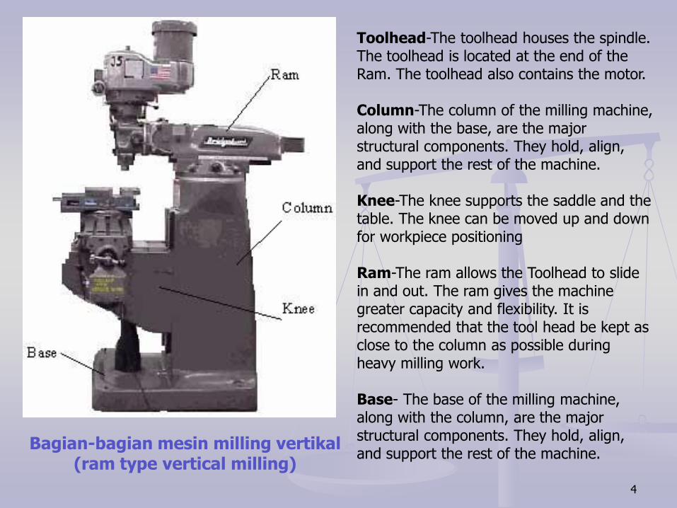
Motor-The motor supplies the power to the spindle. Toolhead-The toolhead houses the spindle. The toolhead is located at the end of the Ram. The toolhead also contains the motor. Column-The column of the milling machine, along with the base, are the major structural components. They hold, align, and support the rest of the machine. Table-Holds and secures the workpiece for machining. Saddle-The saddle it attached to the knee. The saddle provides the in and out, or Y axis travel of the table. Knee-The knee supports the saddle and the table. The knee can be moved up and down for workpiece positioning
Bagian-bagian mesin milling vertikal
4
Toolhead-The toolhead houses the spindle. The toolhead is located at the end of the Ram. The toolhead also contains the motor. Column-The column of the milling machine, along with the base, are the major structural components. They hold, align, and support the rest of the machine. Knee-The knee supports the saddle and the table. The knee can be moved up and down for workpiece positioning Ram-The ram allows the Toolhead to slide in and out. The ram gives the machine greater capacity and flexibility. It is recommended that the tool head be kept as close to the column as possible during heavy milling work. Base- The base of the milling machine, along with the column, are the major structural components. They hold, align, and support the rest of the machine.
Bagian-bagian mesin milling vertikal (ram type vertical milling)

5
Clamps: The knee, table and saddle all come equipped with clamps. The clamps are used to maintain the position of their respective components. All of the clamps should be locked when machining, except the clamp for the axis that is moving. Handles: The table and saddle handles are used to position the part with respect to the tool. Oiler: The oiler feeds lubricant, under pressure, to the knee, table, and the saddle. Always give the oiler "one shot" before you begin operating the machine. Knee Crank-The knee crank is used to raise and lower the knee.
Bagian-bagian mesin milling vertikal

6
Prinsip kerja mesin milling http://www.nmri.go.jp/eng/khirata/metalwork/milling
In the milling machine, a rotating tool cuts a material,
Cutting tool: a drill or an end-mill is used,
The table of the milling machine can be adjusted accurately at the x (side direction), y (toward operator direction) and z (vertical direction).

7
C-frame vertical milling

8
Horizontal milling
9
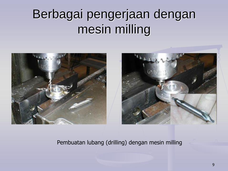
Berbagai pengerjaan dengan
mesin milling
Pembuatan lubang (drilling) dengan mesin milling

10
Berbagai pengerjaan dengan
mesin milling
Meratakan permukaan dengan mesin milling.

11
Berbagai pengerjaan dengan
mesin milling
Memotong salah satu sisi benda kerja

12
Cara memegang atau mencekam benda
kerja

13
Cara memegang atau
mencekam benda kerja

14
Squaring

15
Important Elements for Milling Operation http://www.nmri.go.jp/eng/khirata/metalwork/milling
In the case of the milling process, the rotating speed (putaran pahat), the cutting depth (depth of cut) atau kedalaman pemotongan) and feed rate (sending speed ) are very important.

16
Parts Made with Machining Processes
Figure 24.1 Typical parts and shapes that can be produced
with the machining processes described in this chapter.

17
Milling Cutters and Milling Operations
Figure 24.2 Some basic types of milling cutters and milling operations. (a) Peripheral
milling. (b) Face milling. (c) End milling. (d) Ball-end mill with indexable coated-carbide
inserts machining a cavity in a die block. (e) Milling a sculptured surface with an end mill,
using a five-axis numerical control machine. Source: (d) Courtesy of Iscar. (e) Courtesy
of The Ingersoll Milling Machine Co.

18
Milling Operations
Figure 24.3 (a) Schematic illustration of conventional milling and climb milling. (b) lab-
milling operation showing depth-of-cut, d; feed per tooth, f; chip depth-of-cut, tc; and
workpiece speed, v. (c) Schematic illustration of cutter travel distance, lc, to reach full
depth-of-cut.

19
Face-Milling Operation
Figure 24.4 Face-milling operation showing (a) action of an insert in face
milling; (b) climb milling; (c) conventional milling; (d) dimensions in face milling.
The width of cut, w, is not necessarily the same as the cutter radius.

20
Summary of Peripheral Milling Parameters
and Formulas

21
Face-Milling Cutter with Indexable
Inserts
Figure 24.5 A face-milling cutter with
indexable inserts. Source: Courtesy of
Ingersoll Cutting Tool Company.

22
Effect of
Insert Shape
on Feed
Marks on a
Face-Milled
Surface
Figure 24.6 Schematic illustration of the effect of insert shape on feed marks on a face-
milled surface: (a) small corner radius, (b) corner flat on insert, and (c) wiper, consisting of
small radius followed by a large radius which leaves smoother feed marks. (d) Feed marks
due to various insert shapes.

23
Face-Milling Cutter
Figure 24.7 Terminology for a face-milling cutter.

24
Effect of Lead Angle on Undeformed Chip
Thickness in Face Milling
Figure 24.8 The effect of the lead angle on the undeformed chip thickness in face
milling. Note that as the lead angle increases, the chip thickness decreases, but
the length of contact (i.e., chip width) increases. The edges of the insert must be
sufficiently large to accommodate the contact length increase.
25
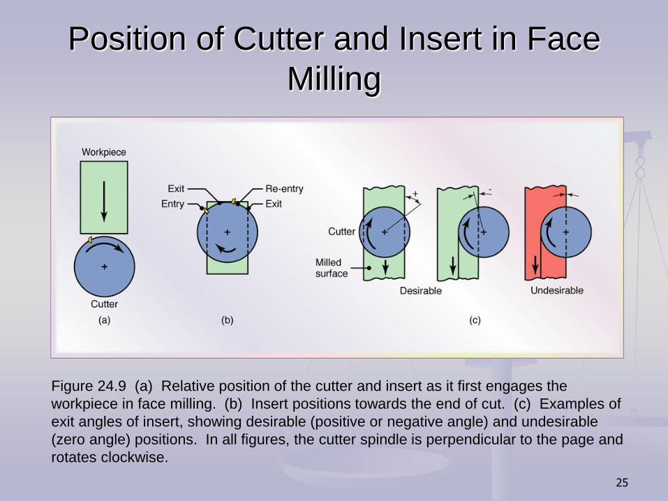
Position of Cutter and Insert in Face
Milling
Figure 24.9 (a) Relative position of the cutter and insert as it first engages the
workpiece in face milling. (b) Insert positions towards the end of cut. (c) Examples of
exit angles of insert, showing desirable (positive or negative angle) and undesirable
(zero angle) positions. In all figures, the cutter spindle is perpendicular to the page and
rotates clockwise.
26
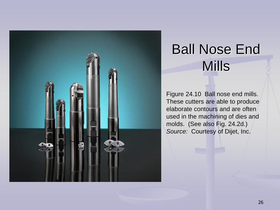
Ball Nose End
Mills
Figure 24.10 Ball nose end mills.
These cutters are able to produce
elaborate contours and are often
used in the machining of dies and
molds. (See also Fig. 24.2d.)
Source: Courtesy of Dijet, Inc.

27
Cutters
Figure 24.11 Cutters for (a) straddle milling, (b) form
milling, (c) slotting, and (d) slitting with a milling cutter.
28
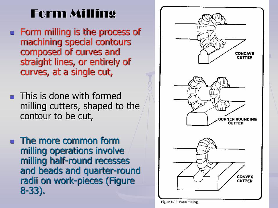
Form Milling
Form milling is the process of machining special contours composed of curves and straight lines, or entirely of curves, at a single cut,
This is done with formed milling cutters, shaped to the contour to be cut,
The more common form milling operations involve milling half-round recesses and beads and quarter-round radii on work-pieces (Figure 8-33).

29
Straddle Milling
When two or more parallel vertical surfaces are machined at a single cut, the operation is called straddle milling.
Straddle milling is accomplished by mounting two side milling cutters on the same arbor, set apart at an exact spacing.
Two sides of the work-piece are machined simultaneously and final width dimensions are exactly controlled.

30
Gang Milling
Beberapa pahat digunakan sekaligus untuk mendapatkan profil tertentu.
Gang milling is the term applied to an operation in which two or more milling cutters are mounted on the same arbor and used when cutting horizontal surfaces.
All cutters may perform the same type of operation or each cutter may perform a different type of operation
31
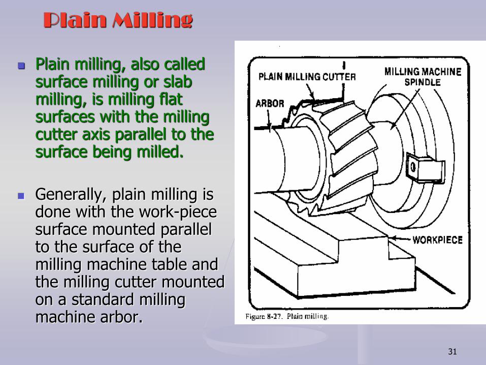
Plain Milling
Plain milling, also called surface milling or slab milling, is milling flat surfaces with the milling cutter axis parallel to the surface being milled.
Generally, plain milling is done with the work-piece surface mounted parallel to the surface of the milling machine table and the milling cutter mounted on a standard milling machine arbor.
32
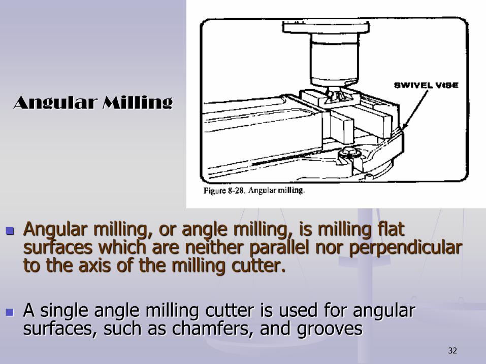
Angular Milling
Angular milling, or angle milling, is milling flat surfaces which are neither parallel nor perpendicular to the axis of the milling cutter.
A single angle milling cutter is used for angular surfaces, such as chamfers, and grooves
33
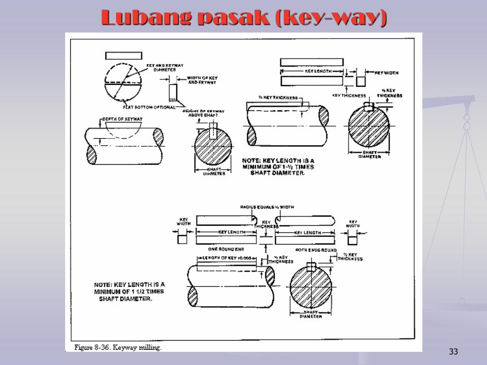
Lubang pasak (key-way)
34
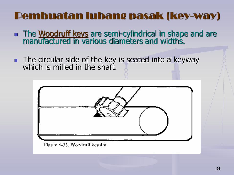
Pembuatan lubang pasak (key-way)
The Woodruff keys are semi-cylindrical in shape and are manufactured in various diameters and widths.
The circular side of the key is seated into a keyway which is milled in the shaft.
35
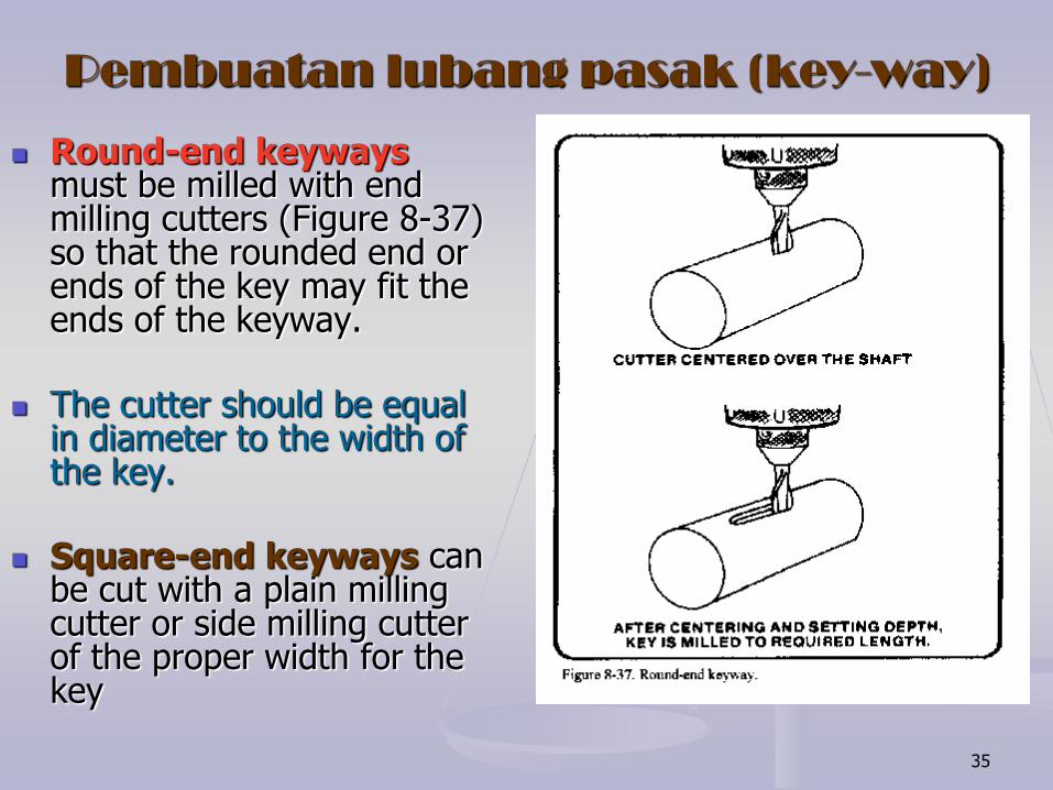
Pembuatan lubang pasak (key-way)
Round-end keyways must be milled with end milling cutters (Figure 8-37) so that the rounded end or ends of the key may fit the ends of the keyway.
The cutter should be equal in diameter to the width of the key.
Square-end keyways can be cut with a plain milling cutter or side milling cutter of the proper width for the key
36
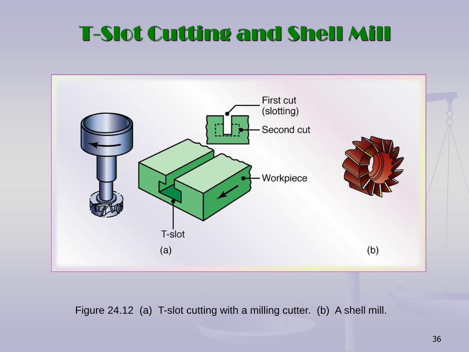
T-Slot Cutting and Shell Mill
Figure 24.12 (a) T-slot cutting with a milling cutter. (b) A shell mill.

37
Pasak bintang (splines)
Splined shafts and fittings are generally cut by bobbing and broaching on special machines.
However, when spline shafts must be cut for a repair job, the operation may be accomplished on the milling machine in a manner similar to that described for cutting keyways.

38
Milling Cutter

39
Milling Cutter

40
Fly Cutter Fly cutting, which is also called single point milling, is one of the most versatile (serba bisa) milling operations,
It is done with a single-point cutting tool shaped like a lathe tool bit. It is held and rotated by a fly cutter arbor,
You can grind this cutter to almost any form that you need, as shown in Figure 8-34.

41
General Recommendations for Milling Operations

42
Troubleshooting Guide for Milling
Operations
43
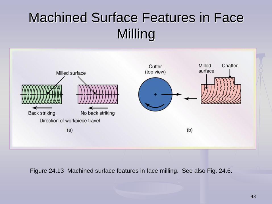
Machined Surface Features in Face
Milling
Figure 24.13 Machined surface features in face milling. See also Fig. 24.6.
44
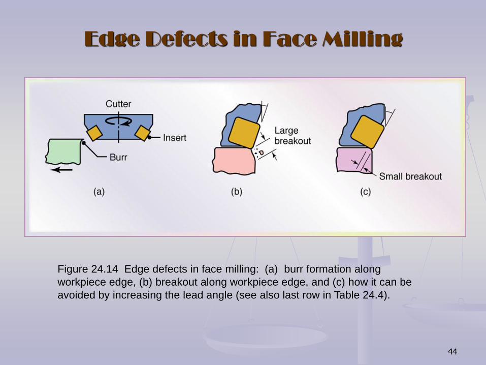
Edge Defects in Face Milling
Figure 24.14 Edge defects in face milling: (a) burr formation along
workpiece edge, (b) breakout along workpiece edge, and (c) how it can be
avoided by increasing the lead angle (see also last row in Table 24.4).

45
Column-and-Knee Type Milling
Machines
Figure 24.15 Schematic illustration of (a) a horizontal-spindle column-and-
knee type milling machine and (b) vertical-spindle column-and-knee type
milling machine. Source: After G. Boothroyd.
46
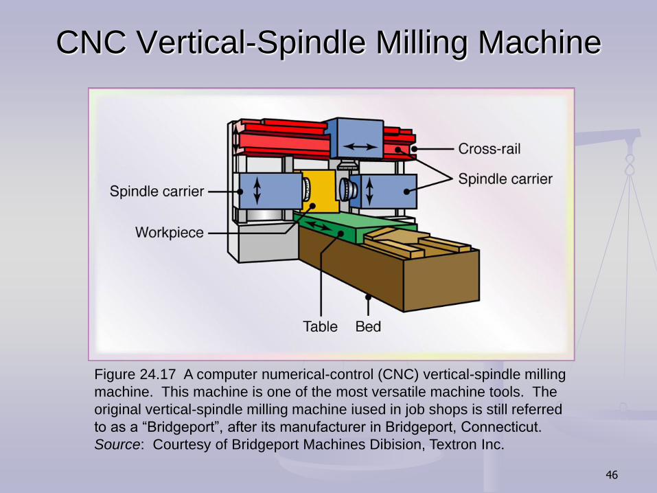
CNC Vertical-Spindle Milling Machine
Figure 24.17 A computer numerical-control (CNC) vertical-spindle milling
machine. This machine is one of the most versatile machine tools. The
original vertical-spindle milling machine iused in job shops is still referred
to as a “Bridgeport”, after its manufacturer in Bridgeport, Connecticut.
Source: Courtesy of Bridgeport Machines Dibision, Textron Inc.

47
Five-Axis Profile Milling Machine
Figure 24.18 Schematic illustration of a five-axis profile milling machine. Note that
there are three principal linear and two angular movements of machine components.