PROJECTS: MOUSEBOT MOUSEY THE JUNKBOT
14
PROJECTS: MOUSEBOT www.makezine.com/02/mousebot 96 Make: Volume 02 Photography by Kirk von Rohr Set up: p.99 Make it: p.100 Use it: p.109 With a few spare parts, you can turn an old computer mouse into an amusing little robot. >> MOUSEY THE JUNKBOT By Gareth Branwyn
Transcript of PROJECTS: MOUSEBOT MOUSEY THE JUNKBOT

PROJECTS: MOUSEBOT www.makezine.com/02/mousebot
96 Make: Volume 02
Ph
oto
gra
ph
y b
y K
irk
vo
n R
oh
r
Set up: p.99 Make it: p.100 Use it: p.109
With a few spare parts, you can turn an old computer mouse into an amusing little robot. >>
MOUSEY THE JUNKBOT By Gareth Branwyn

97Make:
MOUSEY THE JUNKBOT By Gareth Branwyn This project turns an analog computer
mouse into a robot that’ll delight friends and wow workmates down on the cube farm. Mousey’s behavior is fittingly mouse-like. It scoots quickly across the floor, thanks to lively little motors. And when the critter crashes into anything, it speeds off in the opposite direction.
The robot’s “brains” are an ingenious hack based on an audio operational amplifier (op-amp), an 8-pin chip that’s normally used to drive answering machine speakers and other lo-fi equipment. Following Randy Sargent’s pioneering design (see page 102), Mousey repurposes this chip to boost light-sensor input to motor-powerable levels. The result is simple, fast-reacting analog circuitry that fits inside a mouse case.
Gareth Branwyn writes about the intersection of technology and culture for Wired and other publications, and is a member of MAKE's Advisory Board. He is also "Cyborg-in-Chief" of Streettech.com.
THE FINE ART OF MAKING “FRANKENMICE”

98 Make: Volume 02
www.makezine.com/02/mousebotPROJECTS: MOUSEBOT
Illu
stra
tion
by
Tim
my
Ku
cyn
da
INSIDE MOUSEYHow a mild-mannered computer mouse becomes a fast, freewheeling photon-hog.Analog (non-optical) mice pick up movements of the ball with two axles that turn gear-like wheels. The teeth rotate between IR emitters and recep-tors that capture the flickering shadows to read
horizontal and vertical directions and speeds. Reverse-biasing the diode emitters
turns them into Mousey’s “eyes.”
Randy Sargent’s Herbie (below) was the first LM386-based bot. It finished last in the 1996 Robothon’s line-following race, but went on to spawn many descendent designs.
Mousey’s bumper (from one of its buttons) empties a capacitor-full of current across a relay, temporarily crossing the motors’ volt-ages and throwing Mousey into reverse.
The eyes’ light difference is amplified and tapped into the circuit between the two motors, wired in series. As one motor draws less power, the other uses more, steering the bot.

99Make:
SET UP. Visit makezine.com/02/mousebot for source list.
First, you’ll need an analog (non-optical) mouse to cannibalize for its case and several parts inside. If you don’t have an old mouse or two gathering dust, ask friends and colleagues. Otherwise, you can buy a new, super-cheap model such as the Kensington ValueMouse, which costs $10 and has enough space to fit all of your components inside. The big-ger and more symmetrical the mouse, the easier the build will be. “Handed” mice with asymmetrical, curved bodies present problems.
MATERIALS:
Mouse case [A]
2 Light sensorsFrom mouse
SPST touch switch From mouse
Double-pole, double-throw (DPDT) 5-volt relay [B]From analog modem, or Solarbotics #RE1
LM386 audio operational amplifier (op-amp) [C]From answering machine, speakerphone, intercom, etc., or Solarbotics #LM386
2 Small 4.5 VDC motors [D] From motorized toys, or Solarbotics #RM1A / Mabu-chi FF-030-PN
SPST toggle switch [E]Solarbotics #SWT2
2N3904 or PN2222NPN-type transistor [F]Solarbotics #TR3904/TR2222
Light-emitting diode (LED) [G]
2 Spools of 22 to 24-gauge stranded hook-up wire [H] Ideally, 1 black and 1 red
4 Pieces of 22-gauge, solid-core hook-up wire [I] Ideally, 2 red and 2 black,6½" long
9V battery [J]
9V battery snap [K]
1k to 20k resistor [L]
1k resistor [M]
10µF to 100µF electrolytic capacitor [N]
Rubber band or other tire-making material [O] Small piece of plastic [P]At least ¼" x 2½" of hard, springy, thin plastic, like .030" Plasticard stock,or an old credit card
Piece of Velcro or two-way tape (optional)
TOOLS:
Phillips screwdriverFor disassembling mouse
Dremel toolWith bits and cutting discs
Needlenose pliers
Digital multimeter (DMM)
X-ACTO/hobby knife
Soldering iron
Solder sucker ordesoldering bulb
Wire cutters/wire snips
Breadboard, hook-up wire
Superglue, epoxy, orother contact cement
Poster putty, electrical tape, cellophane tape
Ruler
Protective goggles, mask
The other components can be scavenged, or purchased from an electronics retailer. For the motors and other specialty parts, we recommend Dave Hrynkiw’s Solarbotics (solarbotics.com) as an excellent source. Where available, we’ve listed Solarbotics parts numbers for components, and they now offer a complete mousey kit for about $20 (without the mouse).
For an electronic symbols key, see page 113.
I
H
G
N
JA
L
MF
C
E
K
B
DO
P

PROJECTS: MOUSEBOT www.makezine.com/02/mousebot
100 Make: Volume 02
2. PERFORM AN ALIEN MOUSE AUTOPSY Once you have a suitable candidate, remove
all of the mechanics and electronics. Unhook the mouse cable from its plug-type connector, pop out the scroll wheel (if it has one), and then pry out the PCB (printed circuit board). Set these parts aside. Then use your Dremel and cut-off wheel to hollow out the case, removing all of the plastic mounts and partitions inside, except for any screw post(s) that hold the case together. Do the same for the top half, although you may want to leave the mounts that hold the buttons in place. Note: Plastic dust is nasty stuff, so work on news-paper and wear goggles and a mask.
BUILD YOUR ROBOT MOUSE
MAKE IT.
1. MOUSEY’S CIRCUITRY IS FREEFORMED
This means that we’ll solder the parts to each other without a circuit board, building everything up right inside
the mouse case. But before we do this, we’ll need to prep the case and install the motors, and then breadboard the circuitry separately to make sure everything works.
Before unholstering your Dremel tool, you’ll need to determine if the mouse has enough space inside. Unscrew the mouse case and eyeball it to make sure that it will hold the two DC motors and a 9-volt battery. Screws may be hiding under little nylon feet or tape strips on the bottom of the mouse. Save these bits so you can put them back at the end of the build; they’ll help reduce friction.
3. ADD THE POWER SWITCH The last piece of preparatory bodywork is
adding the power switch, a large toggle placed rear topside so it looks like a tail. Find an appropriate mouse-tail location, then drill a hole in the case big enough for the switch. If the switch has a threaded bushing and two nuts, take one nut off, insert the bushing up through the hole, and then tighten the nut back down onto the outside of the case. In some cases, a plastic screw post interferes with the tail area. If so, you can cut out the post and reconnect the top and bottom halves with tape or glue.
The top of our mouse case with its toggle “tail” installed.
Mouse case and parts that need to fit inside.
Cleared-out mouse case.
Battery
Battery Snap
Relay
Motors
LM386
Transistor
Capacitor
Resistor
Bump Switch
Whisker
START>> Time: A Day Complexity: Medium
Illu
stra
tion
s by
Mar
k Fr
auen
feld
er
101Make:
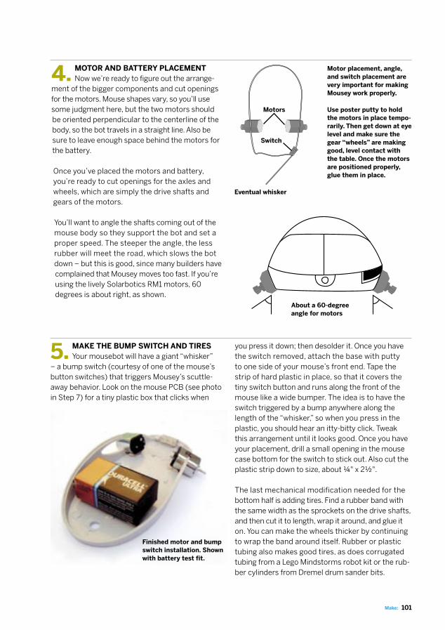
4. MOTOR AND BATTERY PLACEMENT Now we’re ready to figure out the arrange-
ment of the bigger components and cut openings for the motors. Mouse shapes vary, so you’ll use some judgment here, but the two motors should be oriented perpendicular to the centerline of the body, so the bot travels in a straight line. Also be sure to leave enough space behind the motors for the battery.
Once you’ve placed the motors and battery, you’re ready to cut openings for the axles and wheels, which are simply the drive shafts and gears of the motors.
You’ll want to angle the shafts coming out of the mouse body so they support the bot and set a proper speed. The steeper the angle, the less rubber will meet the road, which slows the bot down − but this is good, since many builders have complained that Mousey moves too fast. If you’re using the lively Solarbotics RM1 motors, 60 degrees is about right, as shown.
5. MAKE THE BUMP SWITCH AND TIRES Your mousebot will have a giant “whisker”
− a bump switch (courtesy of one of the mouse’s button switches) that triggers Mousey’s scuttle-away behavior. Look on the mouse PCB (see photo in Step 7) for a tiny plastic box that clicks when
Motor placement, angle, and switch placement are very important for making Mousey work properly.
Use poster putty to hold the motors in place tempo-rarily. Then get down at eye level and make sure the gear “wheels” are making good, level contact with the table. Once the motors are positioned properly, glue them in place.
Finished motor and bump switch installation. Shown with battery test fit.
you press it down; then desolder it. Once you have the switch removed, attach the base with putty to one side of your mouse’s front end. Tape the strip of hard plastic in place, so that it covers the tiny switch button and runs along the front of the mouse like a wide bumper. The idea is to have the switch triggered by a bump anywhere along the length of the “whisker,” so when you press in the plastic, you should hear an itty-bitty click. Tweak this arrangement until it looks good. Once you have your placement, drill a small opening in the mouse case bottom for the switch to stick out. Also cut the plastic strip down to size, about ¼" x 2½".
The last mechanical modification needed for the bottom half is adding tires. Find a rubber band with the same width as the sprockets on the drive shafts, and then cut it to length, wrap it around, and glue it on. You can make the wheels thicker by continuing to wrap the band around itself. Rubber or plastic tubing also makes good tires, as does corrugated tubing from a Lego Mindstorms robot kit or the rub-ber cylinders from Dremel drum sander bits.
Eventual whisker
Motors
Switch
About a 60-degree angle for motors
102 Make: Volume 02
www.makezine.com/02/mousebotPROJECTS: MOUSEBOT
9V- +
3904
LM 386
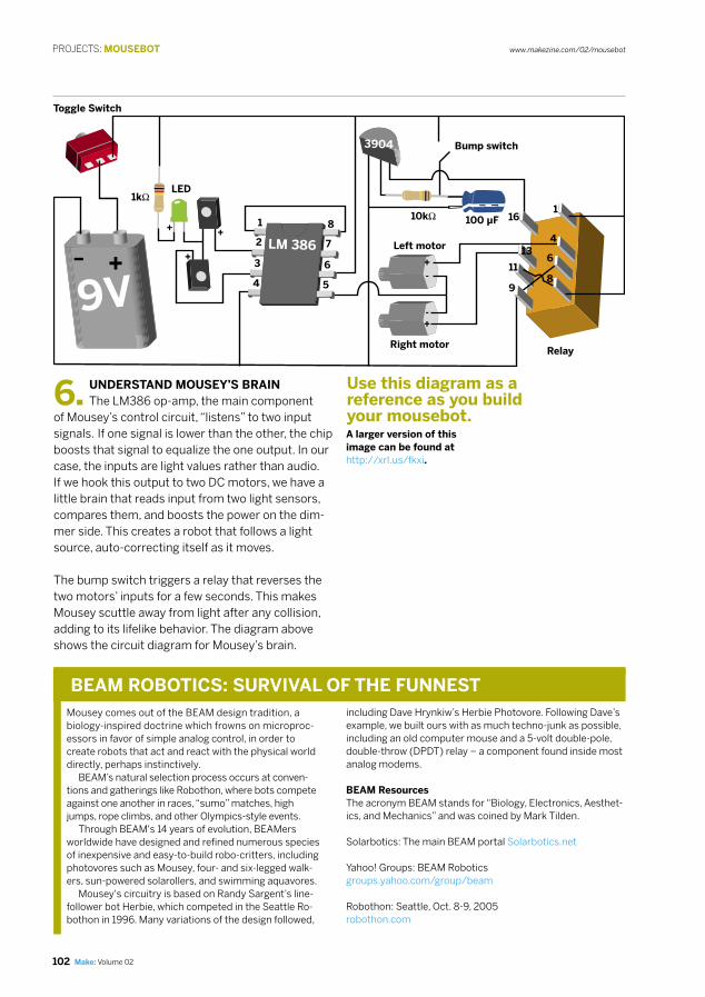
6. UNDERSTAND MOUSEY’S BRAIN The LM386 op-amp, the main component
of Mousey’s control circuit, “listens” to two input signals. If one signal is lower than the other, the chip boosts that signal to equalize the one output. In our case, the inputs are light values rather than audio. If we hook this output to two DC motors, we have a little brain that reads input from two light sensors, compares them, and boosts the power on the dim-mer side. This creates a robot that follows a light source, auto-correcting itself as it moves. The bump switch triggers a relay that reverses the two motors’ inputs for a few seconds. This makes Mousey scuttle away from light after any collision, adding to its lifelike behavior. The diagram above shows the circuit diagram for Mousey’s brain.
A larger version of this image can be found at http://xrl.us/fkxi.
including Dave Hrynkiw’s Herbie Photovore. Following Dave’s example, we built ours with as much techno-junk as possible, including an old computer mouse and a 5-volt double-pole, double-throw (DPDT) relay − a component found inside most analog modems.
BEAM ResourcesThe acronym BEAM stands for “Biology, Electronics, Aesthet-ics, and Mechanics” and was coined by Mark Tilden.
Solarbotics: The main BEAM portal Solarbotics.net
Yahoo! Groups: BEAM Roboticsgroups.yahoo.com/group/beam
Robothon: Seattle, Oct. 8-9, 2005robothon.com
BEAM ROBOTICS: SURVIVAL OF THE FUNNESTMousey comes out of the BEAM design tradition, a biology-inspired doctrine which frowns on microproc-essors in favor of simple analog control, in order to create robots that act and react with the physical world directly, perhaps instinctively. BEAM’s natural selection process occurs at conven-tions and gatherings like Robothon, where bots compete against one another in races, “sumo” matches, high jumps, rope climbs, and other Olympics-style events. Through BEAM's 14 years of evolution, BEAMers worldwide have designed and refined numerous species of inexpensive and easy-to-build robo-critters, including photovores such as Mousey, four- and six-legged walk-ers, sun-powered solarollers, and swimming aquavores. Mousey's circuitry is based on Randy Sargent’s line-follower bot Herbie, which competed in the Seattle Ro-bothon in 1996. Many variations of the design followed,
Toggle Switch
1kΩLED
Bump switch
100 µF10kΩ
RelayRight motor
Left motor
+-
-+
+16
1
4
6
8
13
11
9
+
+
5
8
7
6
4
1
2
3
Use this diagram as a reference as you build your mousebot.

103Make:
8. GIVE MOUSEY EYESTALKS Our IR emitters only have two stubby little
pins coming out. We need to give Mousey some optic nerves − eyestalks that jut from the front of its body. These not only look cool, but also allow you to adjust Mousey’s sensitivity to light by bending the stalks around.
First we need to determine which pin on each emitter is positive and which is negative. Set your digital multimeter to Diode Check mode, and touch the probes to each pin. If the read-out is “OL” (no connection), reverse the probes. When connected correctly, you should get a reading of about 1V, with the red probe indicating the anode (or positive) pin. If your DMM doesn’t have Diode Check, look for a positive voltage of about 0.6V when the red probe is on the anode.
To create the stalks, cut four 6½" pieces of 22-gauge, solid-core hook-up wire. If you have red and black, cut two of each color. Solid core is better than stranded in this case, because it makes stiffer stalks
A pair of IR emitters will serve as your robot’s eyes. Note their likely location on the mouse’s PCB.
Our finished eyestalks, ready to shed some light on our control circuit.
7. CREATE MOUSEY’S EYES For Mousey’s eyes, we can
use the mouse’s own two IR emit-ters, a.k.a. phototransistors. During normal computer mousing, these shine infrared through the mouse’s perforated encoder wheels, which is then received by photodetectors on the other side.
Like many fundamental devices, these emitters can work as both transmit-ters and receivers. As receivers, they’re more robust and less special-ized than the mouse’s dedicated in-ternal photoreceivers, and this makes them a better choice for Mousey’s eyes to the outside world. On most mice, the emitters are clear plastic boxes with a tiny dome protruding from one face, while the detectors are solid black.
Find the clear emitters and desolder them from the PCB. You are now the proud owner of a pair of robot eyeballs.
that hold their shape when you mold them.
Solder the red wire to the cathode (-) pins on the emitters and the black wires to the anode (+) pins. The colors are switched because we're reverse-bias-ing the diodes; with current flowing in the normal direction, additional electrons excited by light in the diode's junction get lost in the flow, but with current trickling the opposite way, the difference is more noticeable, making the circuit more sensitive. When the wires are soldered in place, twist them together and strip some of the jacket off of the other ends.
Switches
IR emitters

PROJECTS: MOUSEBOT www.makezine.com/02/mousebot
104 Make: Volume 02
9. HOOK UP THE OP-AMP With all of your electronic components in
hand, we’re ready to breadboard. Here are the steps to install the op-amp chip and main control circuit:
9a. Install the LM386 chip across the trench on your breadboard. With all ICs, pins are numbered coun-ter-clockwise around, starting at the little dimple.
9b. Connect tie-points for Pins 1 and 8 together with a piece of hook-up wire. These two pins control the op-amp’s gain; by connecting them with a jumper, we’re increasing the circuit’s sensitivity to the input.
9c. Connect the eyestalks by taking the black wires from each and connecting them to tie points for Pins 2 and 3 (the op-amp’s inputs). Connect the red wires together by plugging them into a node about
five or six rows left of the chip. Our horizontally oriented board is organized with +/- power supply at top/bottom and all chips facing left. Translate accordingly for different breadboard layouts.
9d. Plug the negative lead of an LED (the shorter end) into the node with the two red eyestalk wires, and the positive lead into a new node on the oppo-site side of the trench. Then take a 1k-ohm resistor and plug one end into the LED’s positive node, and the other end into the positive/upper power bus. These components constitute a sensitivity-boosting subcircuit originally developed by Wilf Rigter.
9e. Finish this part of your circuit by connecting the power pin of the LM386 (Pin 6) to the positive power bus, and the ground (Pin 4) to the lower/neg-ative bus. We’ll connect the battery later.
The first part of Mousey’s brain: sensors and main control circuit.
10. CREATE THE RUNAWAY CIRCUIT If we hooked up Mousey’s motors and
battery at this point, it would simply chase a light source. Now we’ll make it more interesting by add-ing Mousey’s whisker-triggered “fear” reflex. To cre-ate the runaway circuit, we need the bump switch you already pulled, a 5V DPDT relay, a transistor, and a simple timer consisting of a capacitor and a resistor. When the switch is triggered, the transis-tor enables the runaway circuit, where the capaci-tor powers Mousey’s motors in reverse. When the capacitor has fully discharged a few seconds later, the transistor switches motor control back to the regular, light-following circuit.
The resistance and capacitance determine the rate and amount of current discharged, and you can play with different resistor and cap values until you find the runaway behavior you want. Try resistors in the 1k- to 20k-ohm range, and capacitors in the 10- to 100-microfarad range. With both, the higher the value, the longer the discharge time. We used a 10k-ohm resistor and a 100-microfarad capacitor, which gave about 8 seconds of fast backing up. Here are the steps for breadboarding the runaway circuit:
10a. The relay’s pins are spaced apart widely, so we’ll refer to pins by their breadboard locations. Plug in the relay about six nodes to the right of the LM386, or 1-16 (although the relay actually has only eight pins).

105Make:
10b. Cross a wire from Pin 8 to Pin 11 and another from Pin 6 to Pin 9. These two wires will reverse the motor connections when the relay is engaged.
10c. Plug the capacitor's positive lead into an un-used row just left of the relay, and the cathode to the negative power bus. On electrolytic caps, the cath-ode is usually marked with a stripe or (-) symbol.
10d. Plug in one end of the higher-ohm resistor to connect with the capacitor anode, and jump the other end over the trench to a new node on the other side.
10e. Spread the transistor’s pins and plug it in with the flat side facing the trench, above the relay, such that the center pin (base) connects to the resistor lead, the left pin (emitter) is in an unused node, and the right pin (collector) connects to Pin 16 of the relay.
10f. Plug one hook-up wire into the bottom resistor and capacitor node, somewhere between the two, and a second wire up to the positive power bus. Bend the tips of the wires so they can touch, but keep them separated. These wires will act as the
bump switch when you touch them together. We’re being lazy and assuming that the switch works, but you can hook the wires up to it to make sure.
10g. Run two wires to connect Pin 1 and Pin 8 on the relay with the top/positive power bus. Connect Pin 9 to the negative bus. Finally, connect the transistor’s left pin (emitter) to the bottom/negative bus. This connects the relay and transistor to power.That’s it — look over your cool robot brain!
11. CONNECT THE MOTORS AND POWER Now we’re ready to connect the motors
and power and see if it all works. Take the right motor and connect its negative terminal to Pin 5 of the LM386 chip and its positive terminal to Pin 13 on the relay. Take the left motor and connect its negative to Pin 5 of the chip, and positive to Pin 4 on the relay. On many motors, the positive terminal is marked with a dimple or a (+) symbol.
Finally, connect the 9V battery to the board via a bat-tery snap or clips, recalling that the battery’s “outie” snap is its negative pole. Your breadboard should look like the image at right, and the motors should run. If so, congratulations! Get yourself a flashlight and start having fun moving the beam around Mousey’s light sensors, noticing the speed changes. Then touch the switch wires together, hear the relay click, and see the motors reverse their direction.
If all did not go well, check that everything’s where it should be, with the capacitor, resistors, and transis-tor in the proper holes and power running in the right direction. Some breadboards split their power
Our breadboard with control chip, timer, and relay circuits installed.
Finished breadboard circuit with motors and power attached.
busses into multiple segments; in this case, you need to connect the battery to each occupied seg-ment of the power bus, or else wire them together. Use a fresh battery, and probe around with the multimeter to make sure that the right amount of power is getting where it should. If the eyes don’t work, check the eyestalk solder joins, and if neces-sary, swap the eyeballs out for another set from another old mouse. Some definitely work better than others.
Bump switch leads Power + -
Motors -
Left motor +
Right motor +

106 Make: Volume 02
www.makezine.com/02/mousebotPROJECTS: MOUSEBOT
12. FREEFORM MOUSEY’S CONTROL CIRCUIT Now that we have a light-hungry robot brain, we need to install it in our mouse body so that it can
feed (cue Night of the Living Dead sound effects here). In general, we’ll want to use a lighter wire, such as stranded 22-gauge, to tuck into the case and put less stress on the solder joints.
Before soldering, test fit all the parts inside your case, starting with the battery, motors, and bump switch. Then position the other components around these. The resistor/LED sensitivity-booster circuit will fit against the top half. As you arrange, check that the case still closes, and leave some headroom for the wires. When you’re happy with your arrangement, empty the case and install the battery using two-way tape, Velcro tape, or poster putty. That way, you can replace it when Mousey gets that run-down feeling.
13. INSTALL THE RELAY To prepare the relay for installation, put it
in “dead bug mode” (on its back), and solder short lengths of solid-core wire to the bottom four pins (the switch pins) in an X configuration, as shown.
13a. Solder the transistor’s collector (the right pin when you’re looking at the flat side with the pins pointing down) to the top-left coil pin on the relay, Pin 16 on the breadboard. Solder a 4" piece of black wire (denoting negative) to the transistor’s emitter. This will connect to Pin 4 of the IC and negative power.
13b. Solder a short red wire connecting the top and bottom pins on the relay’s right side, Pins 1 and 8. Solder a 2" black (negative) wire onto the bot-tom-left pin, Pin 9, and then a 3" red wire onto the bottom-right, Pin 8.
14. CONNECT THE SWITCH COMPONENTS
With the relay close to the front, we can chain together the timer resistor, capacitor, and bump switch without needing additional wires. As with the relay, we’ll attach components “out of body” first, for easier soldering.
14a. Solder a 4" black wire to the capacitor’s nega-tive lead (which should be marked).
14b. Using a multimeter on your 3-pin bump switch, determine which side pin connects with the middle pin when you click, and clip off the other side pin.
14c. Solder the cap’s positive lead to the remaining side pin of the bump switch, and solder one end of the timer resistor to the same pole.
13c. Glue the relay into the case, in dead bug mode, and allow it to dry before soldering anything else to it. We glued ours between the motors.
13d. Using red wire, solder the left motor’s positive terminal to the second pin down on the right side (Pin 4 on the breadboard), and solder the right motor’s positive to the opposite pin on the relay, Pin 13.
To left motor +
To Pin 4 on IC (power -)
To timer resistor
To right motor +
To Pin 4 on IC (power -)
Bump switch
To Pin 1 on relay (power +)
- +
To timer transistor
14d. Solder a 2" red lead to the middle bump switch pin, and then glue the switch into the body, through the hole you cut earlier.
14e. Solder a lead between the transistor's middle pin and the free end of the timer resistor.
To Pin 6 on IC (power +)
107Make:
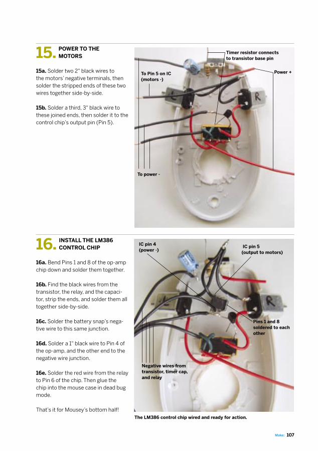
15. POWER TO THE MOTORS
15a. Solder two 2" black wires to the motors’ negative terminals, then solder the stripped ends of these two wires together side-by-side.
15b. Solder a third, 3" black wire to these joined ends, then solder it to the control chip’s output pin (Pin 5).
The LM386 control chip wired and ready for action.
16. INSTALL THE LM386 CONTROL CHIP
16a. Bend Pins 1 and 8 of the op-amp chip down and solder them together.
16b. Find the black wires from the transistor, the relay, and the capaci-tor, strip the ends, and solder them all together side-by-side.
16c. Solder the battery snap’s nega-tive wire to this same junction.
16d. Solder a 1" black wire to Pin 4 of the op-amp, and the other end to the negative wire junction.
16e. Solder the red wire from the relay to Pin 6 of the chip. Then glue the chip into the mouse case in dead bug mode.
That’s it for Mousey’s bottom half!
Power +
Pins 1 and 8 soldered to each other
Negative wires from transistor, timer cap, and relay
To power -
To Pin 5 on IC(motors -)
Timer resistor connects to transistor base pin
IC pin 5(output to motors)
IC pin 4(power -)

108 Make: Volume 02
www.makezine.com/02/mousebotPROJECTS: MOUSEBOT
17. INSTALL MOUSEY’S EYES
17a. The buttons on most computer mice are separate, semi-attached pieces of plastic. To give Mousey’s eyes a solid foundation, glue the buttons down, wait until dry, and then drill small holes in Mousey’s lid to thread the eyestalks through.
17b. Thread about 1¾" of stalk through each hole. On the inside, trim the two red wires so that they just overlap against the underside of the lid, then solder them together. Run the black wires back along the inside and bend them down where the op-amp is located (but don’t solder them yet).
17c. Make the sensitivity booster circuit by cutting a 1" piece of red wire, and soldering one end to the 1k-ohm resistor and the other end to the LED’s anode.
17d. Connect the booster by soldering the free end of the resistor to the middle pole of the toggle switch and the LED cathode to the junction of the two red eyestalk wires.
17e. Mark where the LED sits, gently bend it aside,
Finished insides of mouse top with eyestalk place-ment, sensitivity booster, and power switch.
18. IT’S ALL ABOUT CONNECTIONS We almost got bot! Now install the front
whisker and make the final connections between power, the switch, and the control chip. There’s no photo of these final steps, because they happen in-side a semi-closed mouse. But you’re such a circuit-hackin’ fool by now that you don’t need us anymore.
18a. Solder the black eyestalk wires to Pins 2 and 3 on the LM386.
18b. Solder the red battery wire to either of the side poles of the toggle switch.
18c. Solder a red wire from the toggle’s center pole to Pin 6 of the IC, or to either Pin 1 or Pin 8 of the re-lay. Solder another red lead from the unconnected bump switch pin to one of these same locations.
18d. Cover all exposed leads and junctions with electrical tape to prevent shorts. Then glue or
loosely tape your plastic “whisker” to the bumper switch, so that it clicks on impact.
18e. Finally, snap in the battery, and screw or tape the two mouse halves back together. Then put Mousey on the floor, switch it on, and watch it go.
Congratulations! It’s a slightly anxious, light-seeking robot.
and drill a hole in the case for the LED to poke out of (unless it can already come up through the scroll wheel slot). Push the LED through and hold it in place with electrical tape.
To Pins 2 and 3 of IC
Sensitivity booster subcircuit
FINISH X
NOW GO USE IT »

109Make:
ENJOY YOUR ROBOT MOUSE
USE IT.
RESOURCES This project is adapted from my book Absolute Beginner’s Guide to Building Robots. You can find schematics and installation instructions for additional Mousey hacks on my robot page at Street Tech, streettech.com/robotbook. More cool hardware hacks live in Dave Hrynkiw’s Junkbots, Bugbots & Bots on Wheels. To find other ideas for hacking your Mousey, and other LM386-based bots, Google “robot +LM386,” “herbie +LM386,” and “Randy Sargent +robot.” To learn more about DC motors, and see a dis-sected version of the motor used in this project, see http://xrl.us/fkxh.
MOUSEY GAMESIf all went well, Mousey the Junkbot's behavior will be apparent once you flip its tail. The robot should zoom away and eventually hone in on the brightest area in the room. It works best if you limit Mousey's surroundings to just one source of illumination − one light or sun-soaked window. Here are some other fun experiments: Put Mousey in the hallway and close all doors except one. Make the open room as bright as pos-sible, and see if Mousey eventually scuttles in there. Try orienting Mousey in different starting positions. Tune Mousey's light sensitivity by bending the eyestalks. Move the stalks farther apart, closer together, and bent in different directions until you get the steering you’re looking for. Use a flashlight to lure Mousey around. This will drive pets insane! But be careful; agitated pets will attack your robot and try to rip its components out.
TROUBLESHOOTING A WAYWARD MOUSEYIf you turn on Mousey and nothing happens (cue laughing clarinet, “Wha-wha-WHAAAA”), or if it acts strangely, turn it off immediately. Something went wrong with the build. Here are a few things to check: First, ask yourself the tech-support alpha ques-tion: is it plugged in? Make sure that the battery is new, the battery snap is well-seated, and its positive and negative wires are properly connected. Then make sure that bare wires, pins, and solder joints are not making unauthorized contact with one another. One sign that you may have such a short circuit is if the battery gets warm. Next, double-check all solder connections against the instructions. Besides being in the right places, they should all be fat, shiny, healthy-looking joins. Use the multimeter to check resistances, and resol-der anything suspicious. If Mousey frantically spins in a tight circle, you've probably hooked the motors up incorrectly. Reverse
the wires that connect to the motor on the side that's going backwards. If it's a broader circle, the motors might be wired correctly, but just not level with each other. If so, re-glue the motors so they're symmetrical and make sure the tires are the same size. If Mousey's always heading backwards, swap the wiring on both motors.