Herbie the Mousebot - Solarbotics the... · Herbie the Mousebot is a very speedy light-seeking...
20
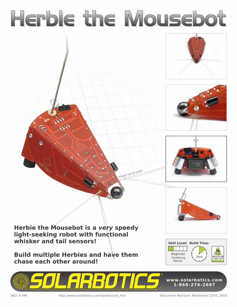
(Soldering Req’d) www.solarbotics.com 1-866-276-2687 RoHS COMPLIANT Document Revision: November 22nd, 2010 SKU: K HM Build Time: 2hrs Skill Level: Beginner http://www.solarbotics.com/products/k_hm/ Herbie the Mousebot is a very speedy light-seeking robot with functional whisker and tail sensors! Build multiple Herbies and have them chase each other around! Image not to scale Herbie the Mousebot Herbie the Mousebot
Transcript of Herbie the Mousebot - Solarbotics the... · Herbie the Mousebot is a very speedy light-seeking...
(SolderingReq’d)
www.solarbotics.com1-866-276-2687
RoHSCOMPLIANT
Document Revision: November 22nd, 2010SKU: K HM
Build Time:
2hrs
Skill Level:
Beginner
http://www.solarbotics.com/products/k_hm/
Herbie the Mousebot is a very speedy light-seeking robot with functional whisker and tail sensors!
Build multiple Herbies and have them chase each other around!
Image not to scale
Herbie the MousebotHerbie the MousebotHerbie the Mousebot
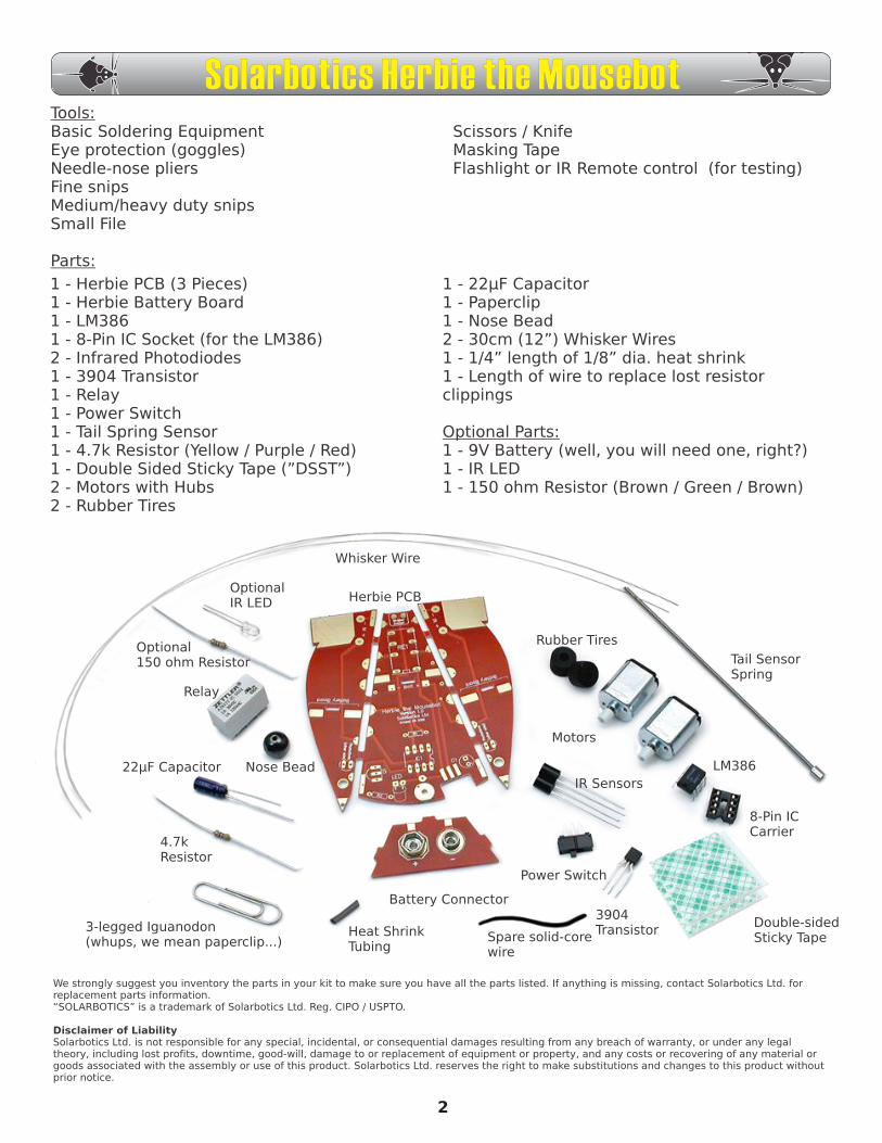
1 - Herbie PCB (3 Pieces)1 - Herbie Battery Board1 - LM3861 - 8-Pin IC Socket (for the LM386)2 - Infrared Photodiodes1 - 3904 Transistor1 - Relay1 - Power Switch1 - Tail Spring Sensor1 - 4.7k Resistor (Yellow / Purple / Red)1 - Double Sided Sticky Tape (”DSST”)2 - Motors with Hubs2 - Rubber Tires
1 - 22µF Capacitor1 - Paperclip1 - Nose Bead2 - 30cm (12”) Whisker Wires1 - 1/4” length of 1/8” dia. heat shrink1 - Length of wire to replace lost resistor clippings
Optional Parts:1 - 9V Battery (well, you will need one, right?)1 - IR LED1 - 150 ohm Resistor (Brown / Green / Brown)
We strongly suggest you inventory the parts in your kit to make sure you have all the parts listed. If anything is missing, contact Solarbotics Ltd. for replacement parts information.“SOLARBOTICS” is a trademark of Solarbotics Ltd. Reg. CIPO / USPTO.
Disclaimer of LiabilitySolarbotics Ltd. is not responsible for any special, incidental, or consequential damages resulting from any breach of warranty, or under any legal theory, including lost profits, downtime, good-will, damage to or replacement of equipment or property, and any costs or recovering of any material or goods associated with the assembly or use of this product. Solarbotics Ltd. reserves the right to make substitutions and changes to this product without prior notice.
Tools:Basic Soldering EquipmentEye protection (goggles)Needle-nose pliersFine snipsMedium/heavy duty snipsSmall File
Parts:
Scissors / KnifeMasking TapeFlashlight or IR Remote control (for testing)
Whisker Wire
Herbie PCB
Battery Connector
Relay
Nose Bead22µF Capacitor
4.7kResistor
3-legged Iguanodon(whups, we mean paperclip...)
3904Transistor
Power Switch
IR Sensors
Rubber Tires
Motors
LM386
8-Pin ICCarrier
Tail SensorSpring
Double-sidedSticky TapeSpare solid-core
wire
Heat ShrinkTubing
OptionalIR LED
Optional150 ohm Resistor
Solarbotics Herbie the Mousebot
2
Background:Many, many moons ago, Randy Sargent was in a pickle. Not literally (yuck), but more of an uncomfortable position of not having a robot to bring to the 1996 Seattle Robothon “Line Follower” contest.
Would you believe the robot he cobbled up out of spare parts the night before the competition actually won?!?
No, neither would we.
It actually ended up in last place, but it still impressed the heck out of everybody with how simple and effective it was. And by using a chip in a very bizarre way, it has very high “cool-hack” scores. The “Herbie” circuit was then released on the Web, and Randy’s super-simple robot was being built all over the world. It’s been featured in “Make” Magazine, and the books “Absolute Beginners Guide to Building Robots”, and “Junkbots, Bugbots, and Bots on Wheels”. Being very simple, quick, and affordable, “Herbie” continues to be a favorite project for junkbot builders.
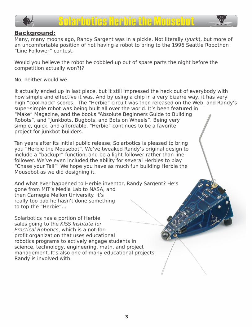
Ten years after its initial public release, Solarbotics is pleased to bring you “Herbie the Mousebot”. We’ve tweaked Randy’s original design to include a “backup!” function, and be a light-follower rather than line-follower. We’ve even included the ability for several Herbies to play “Chase your Tail”! We hope you have as much fun building Herbie the Mousebot as we did designing it.
And what ever happened to Herbie inventor, Randy Sargent? He’s gone from MIT’s Media Lab to NASA, and then Carnegie Mellon University. It’s really too bad he hasn’t done something to top the “Herbie”...
Solarbotics has a portion of Herbie sales going to the KISS Institute for Practical Robotics, which is a not-for-profit organization that uses educational robotics programs to actively engage students in science, technology, engineering, math, and project management. It’s also one of many educational projects Randy is involved with.
3
Solarbotics Herbie the Mousebot
X
X
Soldering - The Essentials:The most important skill needed to successfully construct your device is soldering. Soldering is melting a special metal (called, um..., “solder”) between two components to make an electrical connection. We can also use solder like glue, to build things out of metals.
You must make sure to use electrical solder, and not plumbers solder, which is used for piping and really isn’t good for electronics.
Much like you, solder likes to go where it’s the warmest (this is why Florida is so popular). The trick to successful soldering is to make the parts hot, and the melting solder will run there. If you don’t heat up the parts first, the solder will find the hottest thing around - your soldering iron, and not your parts! Do not melt solder to the tip of your iron and try to smear it onto the parts, as it just won’t work. You’re a roboticist, not a painter!
Successful soldering is generally a 4 step process:
X
4
Solarbotics Herbie the Mousebot
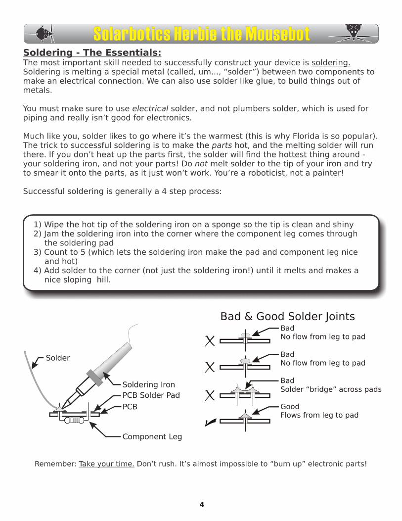
Solder
Soldering Iron
PCB Solder Pad
PCB
Component Leg
Remember: Take your time. Don’t rush. It’s almost impossible to “burn up” electronic parts!
BadNo flow from leg to pad
Good Flows from leg to pad
BadSolder “bridge” across pads
BadNo flow from leg to pad
Bad & Good Solder Joints
1) Wipe the hot tip of the soldering iron on a sponge so the tip is clean and shiny2) Jam the soldering iron into the corner where the component leg comes through
the soldering pad3) Count to 5 (which lets the soldering iron make the pad and component leg nice
and hot)4) Add solder to the corner (not just the soldering iron!) until it melts and makes a
nice sloping hill.
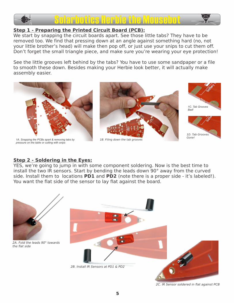
Step 1 - Preparing the Printed Circuit Board (PCB):We start by snapping the circuit boards apart. See those little tabs? They have to be removed too. We find that pressing down at an angle against something hard (no, not your little brother’s head) will make then pop off, or just use your snips to cut them off. Don’t forget the small triangle piece, and make sure you’re wearing your eye protection!
See the little grooves left behind by the tabs? You have to use some sandpaper or a file to smooth these down. Besides making your Herbie look better, it will actually make assembly easier.
1A. Snapping the PCBs apart & removing tabs bypressure on the table or cutting with snips
1B. Filing down the tab grooves
1C. Tab GroovesBad!
1D. Tab Grooves Gone!
Step 2 - Soldering in the Eyes:YES, we’re going to jump in with some component soldering. Now is the best time to install the two IR sensors. Start by bending the leads down 90° away from the curved side. Install them to locations PD1 and PD2 (note there is a proper side - it’s labeled!). You want the flat side of the sensor to lay flat against the board.
2B. Install IR Sensors at PD1 & PD2
2A. Fold the leads 90° towardsthe flat side
2C. IR Sensor soldered in flat against PCB
5
Solarbotics Herbie the Mousebot
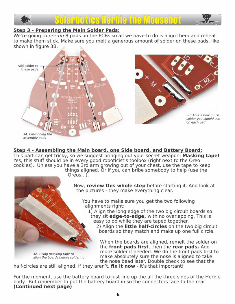
Add solder tothese pads
3A: Pre-tinning the assembly pads
3B: This is how muchsolder you should useon each pad
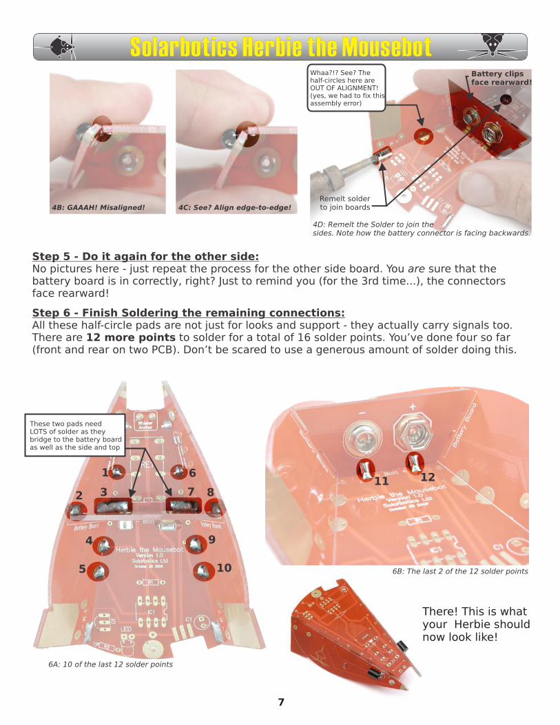
4A: Using masking tape to align the boards before soldering
6
Step 3 - Preparing the Main Solder Pads:We’re going to pre-tin 8 pads on the PCBs so all we have to do is align them and reheat to make them stick. Make sure you melt a generous amount of solder on these pads, like shown in figure 3B.
Solarbotics Herbie the Mousebot
Step 4 - Assembling the Main board, one Side board, and Battery Board:This part can get tricky, so we suggest bringing out your secret weapon: Masking tape! Yes, this stuff should be in every good roboticist’s toolbox (right next to the Oreo cookies). Unless you have a 3rd arm growing out of your chest, use the tape to keep
things aligned. Or if you can bribe somebody to help (use the Oreos...).
Now, review this whole step before starting it. And look at the pictures - they make everything clear.
You have to make sure you get the two following alignments right:
1) Align the long edge of the two big circuit boards so they sit edge-to-edge, with no overlapping. This is easy to do while they are taped together.
2) Align the little half-circles on the two big circuit boards so they match and make up one full circle.
When the boards are aligned, remelt the solder on the front pads first, then the rear pads. Add more solder if needed. We do the front pads first to make absolutely sure the nose is aligned to take the nose bead later. Double check to see that the
half-circles are still aligned. If they aren’t, fix it now - it’s that important!
For the moment, use the battery board to just line up the all the three sides of the Herbie body. But remember to put the battery board in so the connectors face to the rear. (Continued next page)
4B: GAAAH! Misaligned! 4C: See? Align edge-to-edge!
Whaa?!? See? Thehalf-circles here areOUT OF ALIGNMENT!(yes, we had to fix thisassembly error)
4D: Remelt the Solder to join thesides. Note how the battery connector is facing backwards.
Battery clipsface rearward!
Remelt solderto join boards
Step 5 - Do it again for the other side:No pictures here - just repeat the process for the other side board. You are sure that the battery board is in correctly, right? Just to remind you (for the 3rd time...), the connectors face rearward!
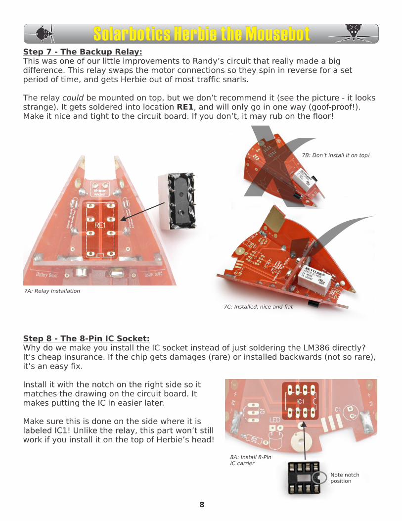
Step 6 - Finish Soldering the remaining connections:All these half-circle pads are not just for looks and support - they actually carry signals too. There are 12 more points to solder for a total of 16 solder points. You’ve done four so far (front and rear on two PCB). Don’t be scared to use a generous amount of solder doing this.
These two pads needLOTS of solder as theybridge to the battery boardas well as the side and top
1
2 3
6
5
87
9
10
4
11 12
There! This is what your Herbie should now look like!
6A: 10 of the last 12 solder points
6B: The last 2 of the 12 solder points
7
Solarbotics Herbie the Mousebot
Step 7 - The Backup Relay:This was one of our little improvements to Randy’s circuit that really made a big difference. This relay swaps the motor connections so they spin in reverse for a set period of time, and gets Herbie out of most traffic snarls.
The relay could be mounted on top, but we don’t recommend it (see the picture - it looks strange). It gets soldered into location RE1, and will only go in one way (goof-proof!). Make it nice and tight to the circuit board. If you don’t, it may rub on the floor!
7A: Relay Installation
7B: Don’t install it on top!
7C: Installed, nice and flat
Step 8 - The 8-Pin IC Socket:Why do we make you install the IC socket instead of just soldering the LM386 directly? It’s cheap insurance. If the chip gets damages (rare) or installed backwards (not so rare), it’s an easy fix.
Install it with the notch on the right side so it matches the drawing on the circuit board. It makes putting the IC in easier later.
Make sure this is done on the side where it is labeled IC1! Unlike the relay, this part won’t still work if you install it on the top of Herbie’s head!
8A: Install 8-PinIC carrier
Note notchposition
8
Solarbotics Herbie the Mousebot
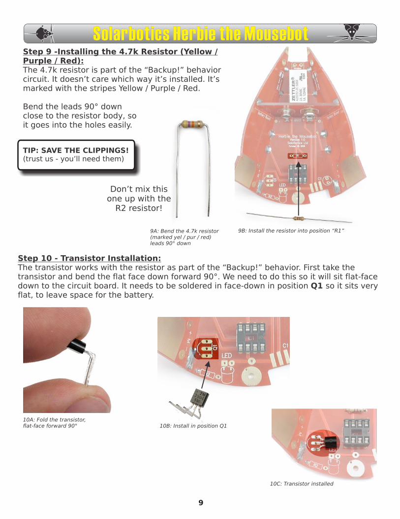
Step 9 -Installing the 4.7k Resistor (Yellow / Purple / Red):The 4.7k resistor is part of the “Backup!” behavior circuit. It doesn’t care which way it’s installed. It’s marked with the stripes Yellow / Purple / Red.
Bend the leads 90° down close to the resistor body, so it goes into the holes easily.
TIP: SAVE THE CLIPPINGS! (trust us - you’ll need them)
9A: Bend the 4.7k resistor(marked yel / pur / red) leads 90° down
9B: Install the resistor into position “R1”
Step 10 - Transistor Installation:The transistor works with the resistor as part of the “Backup!” behavior. First take the transistor and bend the flat face down forward 90°. We need to do this so it will sit flat-face down to the circuit board. It needs to be soldered in face-down in position Q1 so it sits very flat, to leave space for the battery.
10A: Fold the transistor,flat-face forward 90° 10B: Install in position Q1
10C: Transistor installed
Don’t mix thisone up with the
R2 resistor!
9
Solarbotics Herbie the Mousebot
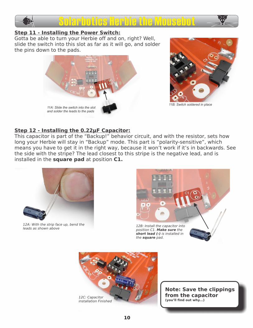
Step 11 - Installing the Power Switch:Gotta be able to turn your Herbie off and on, right? Well, slide the switch into this slot as far as it will go, and solder the pins down to the pads.
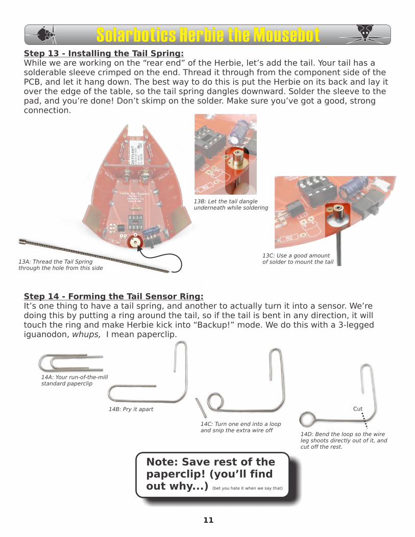
Step 12 - Installing the 0.22µF Capacitor:This capacitor is part of the “Backup!” behavior circuit, and with the resistor, sets how long your Herbie will stay in “Backup” mode. This part is “polarity-sensitive”, which means you have to get it in the right way, because it won’t work if it’s in backwards. See the side with the stripe? The lead closest to this stripe is the negative lead, and is installed in the square pad at position C1.
11A: Slide the switch into the slot and solder the leads to the pads
11B: Switch soldered in place
12A: With the strip face up, bend theleads as shown above
12B: Install the capacitor intoposition C1. Make sure theshort lead (-) is installed inthe square pad.
12C: Capacitor installation Finished
Note: Save the clippingsfrom the capacitor(you’ll find out why...)
10
Solarbotics Herbie the Mousebot
13A: Thread the Tail Springthrough the hole from this side
13B: Let the tail dangleunderneath while soldering
13C: Use a good amountof solder to mount the tail
Step 13 - Installing the Tail Spring:While we are working on the “rear end” of the Herbie, let’s add the tail. Your tail has a solderable sleeve crimped on the end. Thread it through from the component side of the PCB, and let it hang down. The best way to do this is put the Herbie on its back and lay it over the edge of the table, so the tail spring dangles downward. Solder the sleeve to the pad, and you’re done! Don’t skimp on the solder. Make sure you’ve got a good, strong connection.
Step 14 - Forming the Tail Sensor Ring:It’s one thing to have a tail spring, and another to actually turn it into a sensor. We’re doing this by putting a ring around the tail, so if the tail is bent in any direction, it will touch the ring and make Herbie kick into “Backup!” mode. We do this with a 3-legged iguanodon, whups, I mean paperclip.
14A: Your run-of-the-millstandard paperclip
14B: Pry it apart
14C: Turn one end into a loopand snip the extra wire off
14D: Bend the loop so the wireleg shoots directly out of it, andcut off the rest.
Note: Save rest of thepaperclip! (you’ll findout why...) (bet you hate it when we say that)
Cut
11
Solarbotics Herbie the Mousebot

Step 15 - Mounting the Tail Spring Ring:Lay your new ring over the tail spring so the spring is in the middle. You’re doing this so you can see where to bend the wire 90° downward so that it goes into the pad just beside the tail spring.
After you make the bend, insert the wire into the hole so the ring stands about 9mm (3/8”) above the PCB, solder it in, and clip it off so there’s 6mm (1/4”) left underneath (for adjusting).
If you’re out of Oreos to bribe your helper, use some masking tape to hold it at the right height while you solder it in.
15A: Lay ring over spring, and notewhere you have to fold the wire down tomeet the solder pad
15B: Use masking tapeto hold the wire at the9mm (3/8”) while yousolder it in.
9mm(3/8”)
Step 16 - Preparing the Motors:Slide the black rubber tires onto the white plastic hubs on your motors. Don’t push them up too far - rubbing is bad! Find your square of double-sided sticky tape (”DSST”) and half and quarter it.
STOP! WAIT! Don’t do ANYTHING until you read this first: Wipe the motors and PCB mounting spot with alcohol or window cleaner - it makes the DSST stick much better.
Put the motors down in front of you so the white spots are nearest to each other. Put the DSST on the flat part, up near the rear of the motor. Get this part wrong, and your Herbie will love spinning in circles!
16A: Slide the rubber tire onto themotor’s white hub
White spots close!
Tape on clean motor
surface!
16B: DSST stuck on the motors 16C:Solder on wire clippings
12
Peel the backing off one side of the DSST and push it onto one motor hard. Before you do it on the other motor, make sure that with the white dots side-by-side the DSST is on the upper surface of both motors. Then take your clippings, and solder them straight-up on each of the motor posts
Solarbotics Herbie the Mousebot
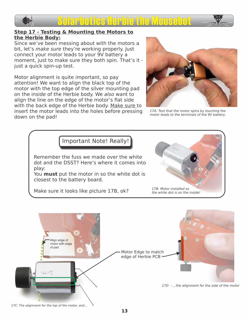
Step 17 - Testing & Mounting the Motors to the Herbie Body:Since we’ve been messing about with the motors a bit, let’s make sure they’re working properly. Just connect your motor leads to your 9V battery a moment, just to make sure they both spin. That’s it - just a quick spin-up test.
Motor alignment is quite important, so pay attention! We want to align the black top of the motor with the top edge of the silver mounting pad on the inside of the Herbie body. We also want to align the line on the edge of the motor’s flat side with the back edge of the Herbie body. Make sure to insert the motor leads into the holes before pressing down on the pad!
Align edge of motor with edge of pad
Motor Edge to match edge of Herbie PCB
17C: The alignment for the top of the motor, and...
17D : ...the alignment for the side of the motor
Important Note! Really!
Remember the fuss we made over the white dot and the DSST? Here’s where it comes into play:You must put the motor in so the white dot is closest to the battery board.
Make sure it looks like picture 17B, ok? 17B: Motor installed so the white dot is on the inside!
17A: Test that the motor spins by touching the motor leads to the terminals of the 9V battery.
13
Solarbotics Herbie the Mousebot
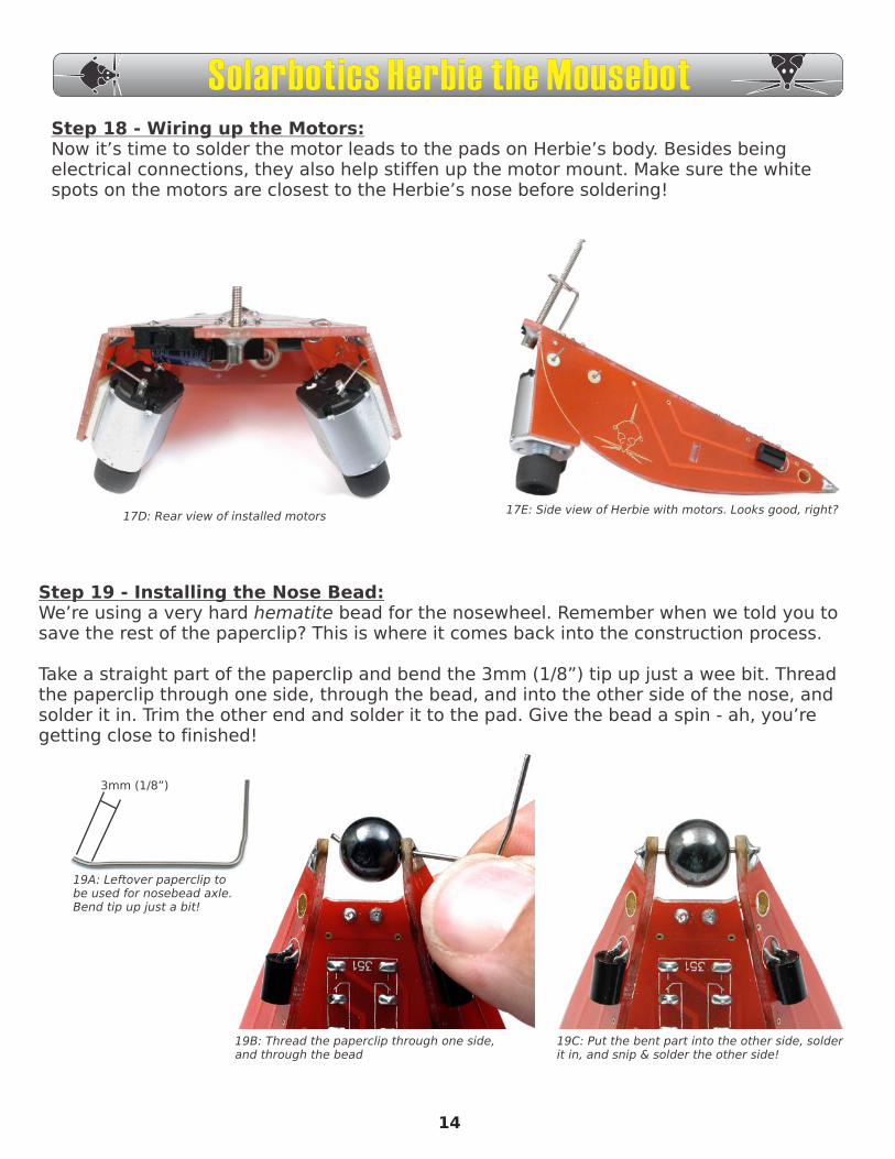
Step 19 - Installing the Nose Bead:We’re using a very hard hematite bead for the nosewheel. Remember when we told you to save the rest of the paperclip? This is where it comes back into the construction process.
Take a straight part of the paperclip and bend the 3mm (1/8”) tip up just a wee bit. Thread the paperclip through one side, through the bead, and into the other side of the nose, and solder it in. Trim the other end and solder it to the pad. Give the bead a spin - ah, you’re getting close to finished!
3mm (1/8”)
19A: Leftover paperclip tobe used for nosebead axle.Bend tip up just a bit!
19B: Thread the paperclip through one side,and through the bead
19C: Put the bent part into the other side, solderit in, and snip & solder the other side!
Step 18 - Wiring up the Motors:Now it’s time to solder the motor leads to the pads on Herbie’s body. Besides being electrical connections, they also help stiffen up the motor mount. Make sure the white spots on the motors are closest to the Herbie’s nose before soldering!
17D: Rear view of installed motors17E: Side view of Herbie with motors. Looks good, right?
14
Solarbotics Herbie the Mousebot
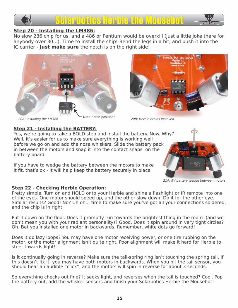
Step 20 - Installing the LM386:No slow 286 chip for us, and a 486 or Pentium would be overkill (just a little joke there for anybody over 30...). Time to install the chip! Bend the legs in a bit, and push it into the IC carrier - Just make sure the notch is on the right side!
20A: Installing the LM386Note notch position!
20B: Herbie brains installed
Step 21 - Installing the BATTERY:Yes, we’re going to take a BOLD step and install the battery. Now. Why? Well, it’s easier for us to make sure everything is working well before we go on and add the nose whiskers. Slide the battery pack in between the motors and snap it into the contact snaps on the battery board.
If you have to wedge the battery between the motors to make it fit, that’s ok - it will help keep the battery securely in place.
21A: 9V battery wedge between motors
Step 22 - Checking Herbie Operation:Pretty simple. Turn on and HOLD onto your Herbie and shine a flashlight or IR remote into one of the eyes. One motor should speed up, and the other slow down. Do it for the other eye. Similar results? Good! No? Uh oh... time to make sure you’ve got all your connections soldered, and the chip is in right.
Put it down on the floor. Does it promptly run towards the brightest thing in the room (and we don’t mean you with your radiant personality)? Good. Does it spin around in very tight circles? Oh. Bet you installed one motor in backwards. Remember, white dots go forward!
Does it do lazy loops? You may have one motor receiving power, or one tire rubbing on the motor, or the motor alignment isn’t quite right. Poor alignment will make it hard for Herbie to steer towards light!
Is it continually going in reverse? Make sure the tail-spring ring isn’t touching the spring tail. If this doesn’t fix it, you may have both motors in backwards. When you hit the tail sensor, you should hear an audible “click”, and the motors will spin in reverse for about 3 seconds.
So everything checks out fine? It seeks light, and reverses when the tail is touched? Cool. Pop the battery out, add the whisker sensors and finish your Solarbotics Herbie the Mousebot!
15
Solarbotics Herbie the Mousebot
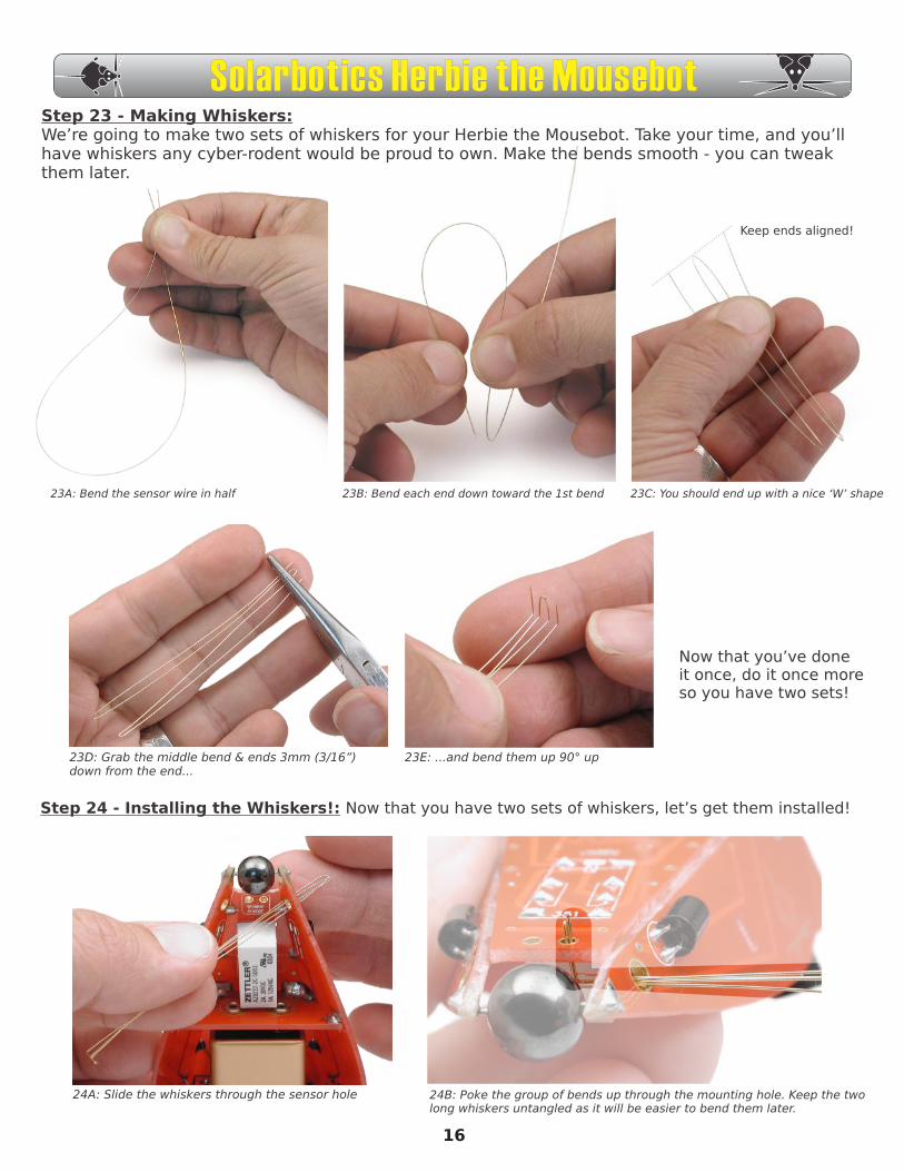
Step 23 - Making Whiskers:We’re going to make two sets of whiskers for your Herbie the Mousebot. Take your time, and you’ll have whiskers any cyber-rodent would be proud to own. Make the bends smooth - you can tweak them later.
23A: Bend the sensor wire in half 23B: Bend each end down toward the 1st bend 23C: You should end up with a nice ‘W’ shape
23D: Grab the middle bend & ends 3mm (3/16”)down from the end...
23E: ...and bend them up 90° up
Step 24 - Installing the Whiskers!: Now that you have two sets of whiskers, let’s get them installed!
Now that you’ve done it once, do it once more so you have two sets!
24A: Slide the whiskers through the sensor hole 24B: Poke the group of bends up through the mounting hole. Keep the twolong whiskers untangled as it will be easier to bend them later.
Keep ends aligned!
16
Solarbotics Herbie the Mousebot
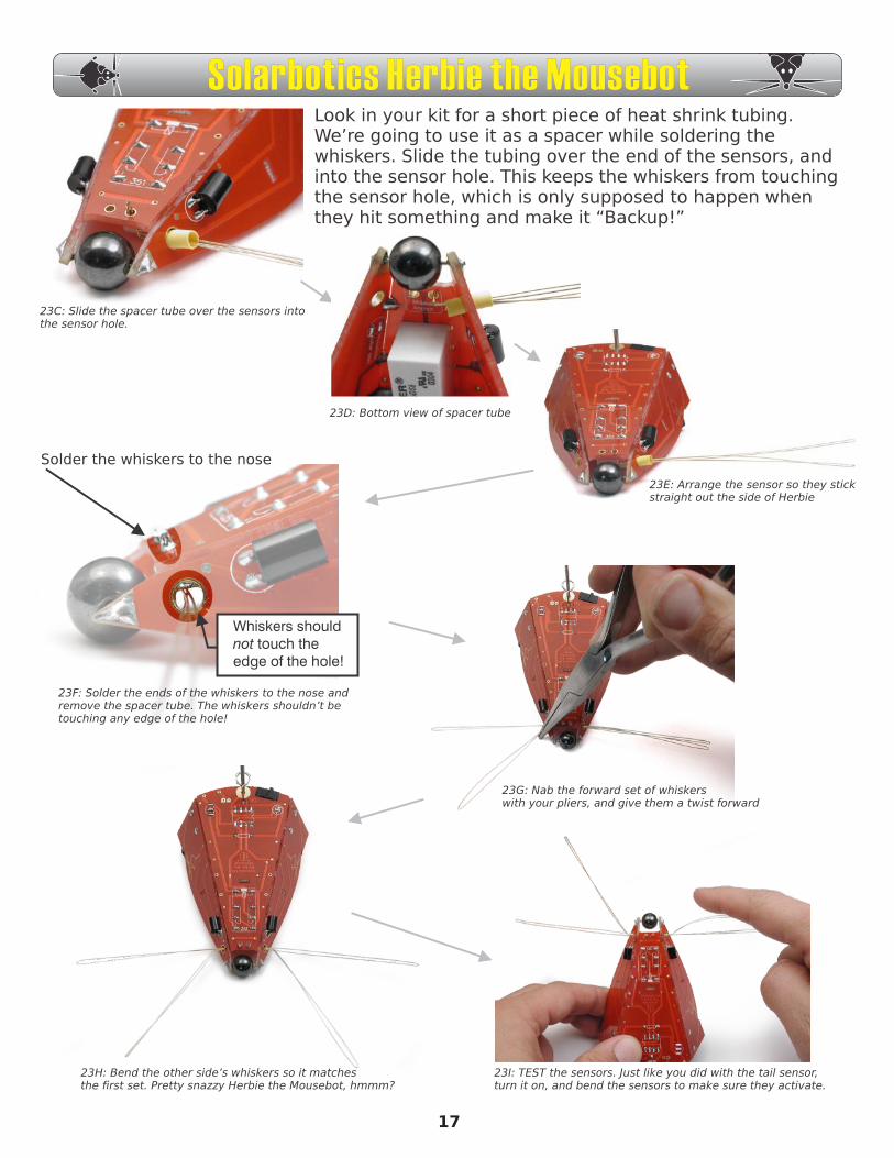
23C: Slide the spacer tube over the sensors intothe sensor hole.
23D: Bottom view of spacer tube
23E: Arrange the sensor so they stickstraight out the side of Herbie
23F: Solder the ends of the whiskers to the nose and remove the spacer tube. The whiskers shouldn’t be touching any edge of the hole!
Solder the whiskers to the nose
23G: Nab the forward set of whiskerswith your pliers, and give them a twist forward
23H: Bend the other side’s whiskers so it matchesthe first set. Pretty snazzy Herbie the Mousebot, hmmm?
23I: TEST the sensors. Just like you did with the tail sensor,turn it on, and bend the sensors to make sure they activate.
17
Look in your kit for a short piece of heat shrink tubing. We’re going to use it as a spacer while soldering the whiskers. Slide the tubing over the end of the sensors, and into the sensor hole. This keeps the whiskers from touching the sensor hole, which is only supposed to happen when they hit something and make it “Backup!”
Solarbotics Herbie the Mousebot
Whiskers should not touch the edge of the hole!
Troubleshooting!The Solarbotics Herbie the Mousebot is a pretty straightforward device, so let’s step through the list and hopefully we’ll find your problem. If not, give us a call, and we’ll be happy to work with you to fix it.
1. “Nothing is happening!” - Even without the chip, Herbie should do something, so there must be a problem with power. Make sure you have the soldered the power tabs on the battery board to the main board. They’re located directly underneath the battery snaps (see step 6, photo 6B!). Oh, and did you remember to turn it on? It should turn on with the switch moved towards the tail.
2. “Herbie is spinning really fast!” - This usually means one of the motors is installed backwards. Pick Herbie up, and feel each motor spin. Unless if it’s in “Backup!” mode, the wheels should be trying to push Herbie forward. When you’ve found which motor is in backwards, the easiest fix is to just cross-wire the motor connections to the PCB. It’s much easier than prying the motor out and turning it around.
3. “Herbie is spinning in wide circles!” - This happens when either one of the motors isn’t working very well, so check to see that the rubber didn’t creep up to rub against the motor. Or the motor shaft may be gunked up with loose hair causing it to slow down. Or one of the motors is way out of alignment. As long as both motors are mounted in pretty much the same way, Herbie will be perfectly happy. If one is wacky, it’ll do donuts!
4. “Why is Herbie always running in reverse?” - One of two reasons: 1) Both motors were installed backwards (see problem 2 to fix), or 2) The “Backup!” circuit is stuck on. Listen closely when you turn Herbie on - do you hear a “click”? If so, that’s the relay turning on, which means either your tail spring sensor or your whiskers are making contact with the touch rings. Check each and make sure that the whiskers/tail do not touch the rings that surround them. If this isn’t the case, make sure you didn’t accidently make a solder bridge from the tail spring to the tail ring (see step 13, picture 13A!).
5. “Herbie isn’t responding to anything - it just runs straight!” - Betcha the LM386 chip is in backwards, or missing!
6. “My dog chewed on Herbie, and now it’s acting strange...” - Well, wouldn’t you? What you’re seeing is dog drool affecting the circuitry. Wipe off the top of Herbie with a paper towel and some glass cleaner or alcohol, and let it dry. Herbie will recover just fine!
7. “My cat is rubbing her eye...” - As cute as Herbie is, it isn’t a pet toy. Don’t let Herbie poke your pets!
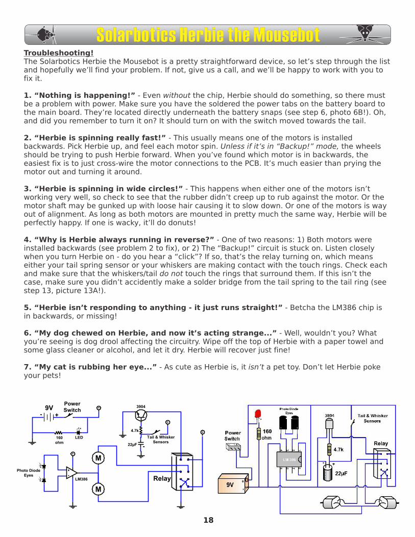
M
M
+
+
+
Relay
+
+
-
9V
160ohm
LED
Photo DiodeEyes
LM386
Tail & WhiskerSensors
22µF -
4.7k
PowerSwitch
3904
18
Solarbotics Herbie the Mousebot
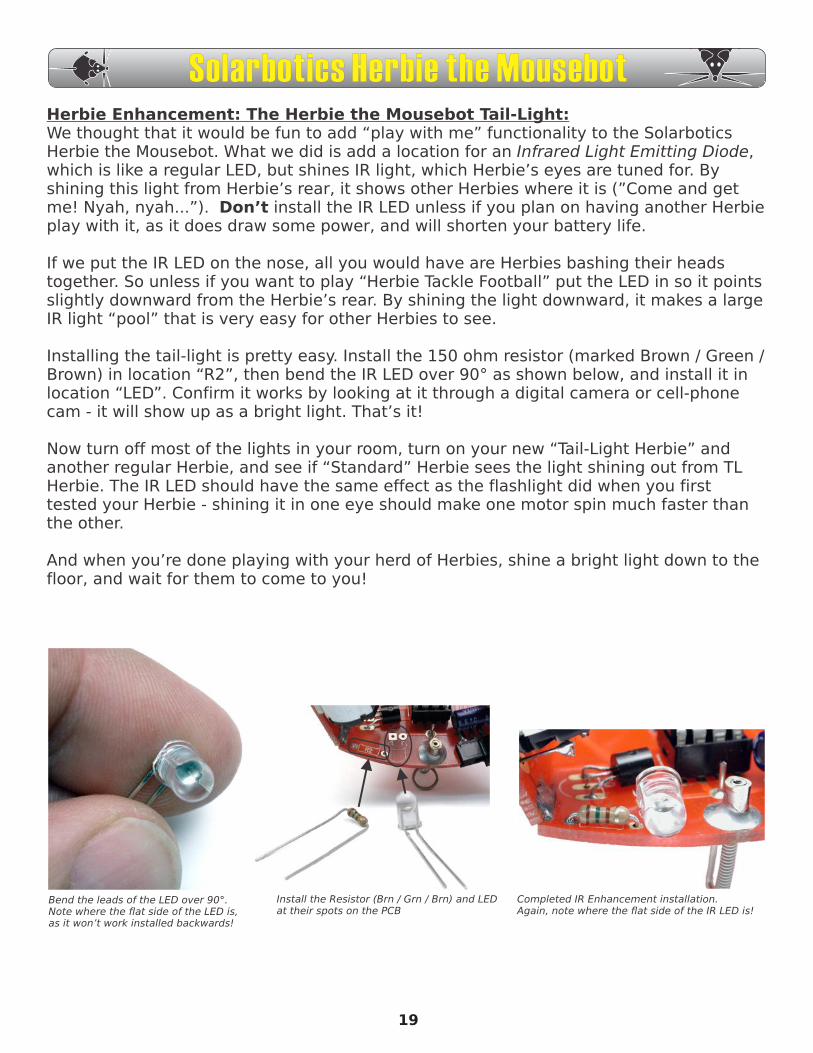
Herbie Enhancement: The Herbie the Mousebot Tail-Light:We thought that it would be fun to add “play with me” functionality to the Solarbotics Herbie the Mousebot. What we did is add a location for an Infrared Light Emitting Diode, which is like a regular LED, but shines IR light, which Herbie’s eyes are tuned for. By shining this light from Herbie’s rear, it shows other Herbies where it is (”Come and get me! Nyah, nyah...”). Don’t install the IR LED unless if you plan on having another Herbie play with it, as it does draw some power, and will shorten your battery life.
If we put the IR LED on the nose, all you would have are Herbies bashing their heads together. So unless if you want to play “Herbie Tackle Football” put the LED in so it points slightly downward from the Herbie’s rear. By shining the light downward, it makes a large IR light “pool” that is very easy for other Herbies to see.
Installing the tail-light is pretty easy. Install the 150 ohm resistor (marked Brown / Green / Brown) in location “R2”, then bend the IR LED over 90° as shown below, and install it in location “LED”. Confirm it works by looking at it through a digital camera or cell-phone cam - it will show up as a bright light. That’s it!
Now turn off most of the lights in your room, turn on your new “Tail-Light Herbie” and another regular Herbie, and see if “Standard” Herbie sees the light shining out from TL Herbie. The IR LED should have the same effect as the flashlight did when you first tested your Herbie - shining it in one eye should make one motor spin much faster than the other.
And when you’re done playing with your herd of Herbies, shine a bright light down to the floor, and wait for them to come to you!
Bend the leads of the LED over 90°.Note where the flat side of the LED is, as it won’t work installed backwards!
Install the Resistor (Brn / Grn / Brn) and LED at their spots on the PCB
Completed IR Enhancement installation.Again, note where the flat side of the IR LED is!
19
Solarbotics Herbie the Mousebot
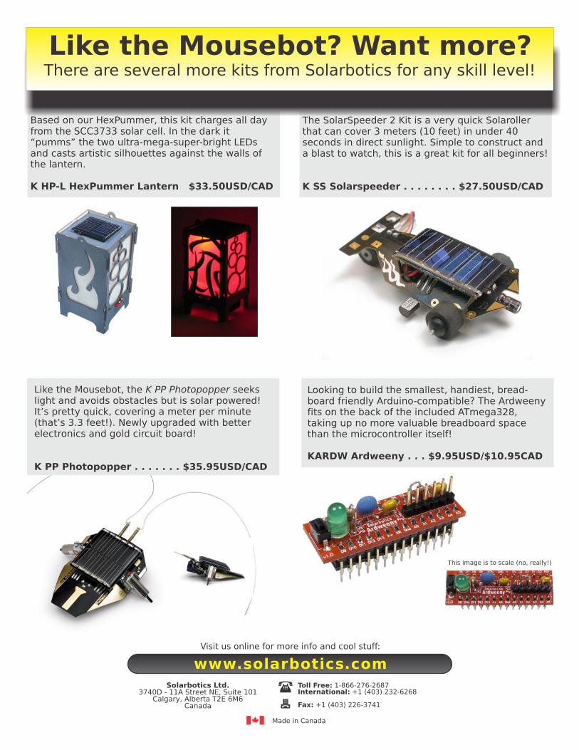
Based on our HexPummer, this kit charges all day from the SCC3733 solar cell. In the dark it “pumms” the two ultra-mega-super-bright LEDs and casts artistic silhouettes against the walls of the lantern.
K HP-L HexPummer Lantern $33.50USD/CAD
The SolarSpeeder 2 Kit is a very quick Solaroller that can cover 3 meters (10 feet) in under 40 seconds in direct sunlight. Simple to construct and a blast to watch, this is a great kit for all beginners!
K SS Solarspeeder . . . . . . . . $27.50USD/CAD
Like the Mousebot, the K PP Photopopper seeks light and avoids obstacles but is solar powered! It’s pretty quick, covering a meter per minute (that’s 3.3 feet!). Newly upgraded with better electronics and gold circuit board!
K PP Photopopper . . . . . . . $35.95USD/CAD
Like the Mousebot? Want more?There are several more kits from Solarbotics for any skill level!
Looking to build the smallest, handiest, bread-board friendly Arduino-compatible? The Ardweeny fits on the back of the included ATmega328, taking up no more valuable breadboard space than the microcontroller itself!
KARDW Ardweeny . . . $9.95USD/$10.95CAD
This image is to scale (no, really!)
Solarbotics Ltd.
3740D - 11A Street NE, Suite 101Calgary, Alberta T2E 6M6
Canada
Toll Free: 1-866-276-2687International: +1 (403) 232-6268
Fax: +1 (403) 226-3741
Made in Canada
Visit us online for more info and cool stuff:
www.solarbotics.com