Project Report -...
13
Project Report Project Name: Wireless water level indicator. Submitted by: 13-02-05- 004-Symoon Hasan 13-02-05- 016-Md. Faisal Karim 13-02-05-029-A.N.M Nazeb Hasan Introduction: The Water Level Indicator employs a simple mechanism to detect and indicate the water level in an overhead tank or any other water container. The main objective of this project is to develop an embedded system, which is a wireless water level indicator by using RF. Using this system, you can remotely monitor the water level of an overhead tank that is placed up to 50 metres away. The system features an RF transmitter receiver pair, doing away with the need to run wires from the roof to ground. The transmitter is placed near the tank with sensors inside the tank to monitor the level of water. The sensed level is streamed wirelessly through the RF transmitter. This is received by the receiver unit placed remotely and decoded to indicate the water level on an LCD. Instrument:
-
Upload
trinhquynh -
Category
Documents
-
view
221 -
download
5
Transcript of Project Report -...

Project Report
Project Name: Wireless water level indicator.
Submitted by:
13-02-05- 004-Symoon Hasan
13-02-05- 016-Md. Faisal Karim
13-02-05-029-A.N.M Nazeb Hasan
Introduction:
The Water Level Indicator employs a simple mechanism to detect and indicate the water level
in an overhead tank or any other water container. The main objective of this project is to
develop an embedded system, which is a wireless water level indicator by using RF. Using this
system, you can remotely monitor the water level of an overhead tank that is placed up to 50
metres away. The system features an RF transmitter receiver pair, doing away with the need to
run wires from the roof to ground. The transmitter is placed near the tank with sensors inside
the tank to monitor the level of water. The sensed level is streamed wirelessly through the RF
transmitter. This is received by the receiver unit placed remotely and decoded to indicate the
water level on an LCD.
Instrument:

RF modules TX433 and RX433
HC-SR04 Ultrasonic Sensor
Copper wire
Encoder [HT12E] & Decoder [HT12D]
Lcd Display 2 X 16
Breadboard
LED
Jumper wires
Arduino uno
Resistor(33k & 1M)
Circuit Diagram:


Image view:

Working Principles:
First we connected the ultrasonic sensor with the arduino.Then we collected data by using ultrasonic
sensor.These measured data were stored in encoder.Then it were carried by RF transmitter and
received by RF receiver.After this,the received data were placed in the decoder.Then these data were
shown in LCD display.
Ultrasonic Sensor:
Ultrasonic sensors emit short, high-frequency sound pulses at regular intervals. These propagate in the
air at the velocity of sound. If they strike an object, then they are reflected back as echo signals to the
sensor, which itself computes the distance to the target based on the time-span between emitting the
signal and receiving the echo. As the distance to an object is determined by measuring the time of flight
and not by the intensity of the sound, ultrasonic sensors are excellent at suppressing background
interference.

RF Module with Encoder & Decoder:
A general RF communication block diagram is shown below. Since most of the
encoders/decoders/microcontrollers are TTL compatible, most of the inputs by the user will be given in
TTL logic level. Thus, this TTL input is to be converted into serial data input using an encoder or a
microcontroller. This serial data can be directly read using the RF Transmitter, which then performs ASK
(in some cases FSK) modulation on it and transmit the data through the antenna.
In the receiver side, the RF Receiver receives the modulated signal through the antenna, performs all
kinds of processing, filtering, demodulation, etc and gives out a serial data. This serial data is then
converted to a TTL level logic data, which is the same data that the user has input.
The most popular serial encoder/decoder used is the HT12D-HT12E pair. Their description is given
below. It’s okay if you don’t understand what is written there. Just make sure you go through the pin
configurations and the circuit implementation.
The HT12E Encoder ICs are series of CMOS LSIs for Remote Control system applications. They are
capable of Encoding 12 bit of information which consists of N address bits and 12-N data bits. Each
address/data input is externally trinary programmable if bonded out.

HT12E Pin
The HT12D Decoder ICs are series of CMOS LSIs for remote control system applications. This ICs are
paired with each other. For proper operation a pair of encoder/decoder with the same number of
address and data format should be selected. The Decoder receive the serial address and data from its
corresponding encoder, transmitted by a carrier using an RF transmission medium and gives output to
the output pins after processing the data.
LCD PIN DTAILS:
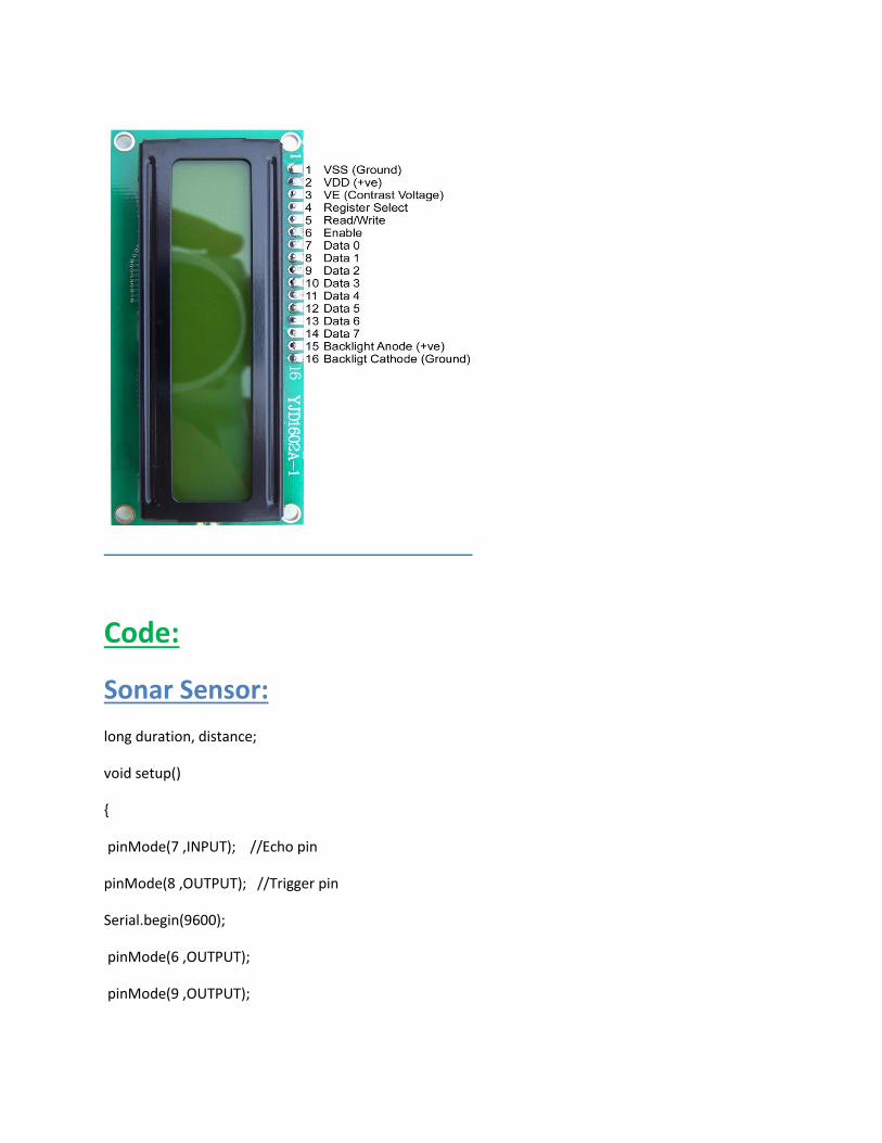
Code:
Sonar Sensor:
long duration, distance;
void setup()
{
pinMode(7 ,INPUT); //Echo pin
pinMode(8 ,OUTPUT); //Trigger pin
Serial.begin(9600);
pinMode(6 ,OUTPUT);
pinMode(9 ,OUTPUT);

pinMode(10 ,OUTPUT);
pinMode(13 ,OUTPUT);
}
void loop()
{digitalWrite(8, LOW);
delayMicroseconds(2);
digitalWrite(8, HIGH);
delayMicroseconds(10);
digitalWrite(8, LOW);
duration = pulseIn(7, HIGH);
distance = duration/58.2;
Serial.println(distance);
delay(500);
if (distance<20&&distance>15)
{digitalWrite(6, HIGH);
digitalWrite(9 , LOW);}
if (distance<30&&distance>25)
{digitalWrite(10, LOW);
digitalWrite(6 , LOW);
digitalWrite(9, HIGH);
}

if (distance<40&&distance>35)
{digitalWrite(13, LOW);
digitalWrite(10, HIGH);
digitalWrite(9 , LOW);
}
if (distance<50&&distance>45)
{
digitalWrite(13, HIGH);
digitalWrite(10 , LOW);
}
}
Lcd Display:
#include <LiquidCrystal.h>
LiquidCrystal lcd(12, 11, 5, 4, 3, 2);
void setup() {
lcd.begin(16, 2);
pinMode(13 ,OUTPUT);
pinMode(6,OUTPUT);
pinMode(9 ,OUTPUT);
pinMode(10,OUTPUT);
Serial.begin(9600);
lcd.print("lcd on");
}
void loop() {

if (digitalRead(13) == HIGH)
{lcd.clear();
lcd.setCursor(0, 0);
lcd.print("Remainig space above 45 cm");
}
if (digitalRead(6) == HIGH)
{lcd.clear();
lcd.setCursor(0, 0);
lcd.print("Remainig space above 15 cm");
}
if (digitalRead(9) == HIGH)
{lcd.clear();
lcd.setCursor(0, 0);
lcd.print("Remainig space above 25 cm");
}
if (digitalRead(10) == HIGH)
{lcd.clear();
lcd.setCursor(0, 0);
lcd.print("Remainig space above 35 cm");
}
}
Troubleshooting:
130205029:
1.I got a problem to upload the code,it happened because port was not selected.

2.When water level increased Led was on.but when water level decreased led did not respond
serially.then I noticed that I did not write the code properly.When one pin was high,other pin had to be
low.
130205004:
1.In setup I did not use 1M ohm in Encoder.But it was necessary for the setup.
2.At first Sonar sensor did not work.then I found that in void setup I wrote
pinMode(7 ,OUTPUT); //Echo pin
It had to be pinMode(7 ,INPUT);
130205016:
1.Lcd was not working as I did not connect the digital pin correctly.and also for the loose connection of
Pot.
2.Lcd did not show the level as I did not use lcd.clear();
Before every lcd.print();
Water Level Indicator Project Circuit Features:
1.Easy installation.
2.Low maintenance.
3.Compact elegant design.
4.The Automatic water level controller ensures no overflows or dry running of pump there by saves
electricity and water. Avoid seepage of roofs and walls due to overflowing tanks.
5.Fully automatic, saves man power.
6.Consume very little energy, ideal for continuous operation.
7.Automatic water level controller provides you the flexibility to decide for yourself the water levels for
operations of pump set.
8.Shows clear indication of water levels in the overhead tank.
Discussion:
Though water level indicator is a simple project,it has great significance.We can prevent water from
being wasted by using it.We can also avoid seepage of roofs and walls due to overflowing tanks.As it is
fully automatic,we can save man power by using water level indicator.It consumes low power,so it saves
electricity.Though we faced some troubleshooting during the making of this project,we overcame it by
the help of our course teacher.We can also add some further improvement in this project.We are

planning to add buzzer in our project.By adding buzzer we can know about the water level without
monitoring the LCD display.