
Project Name: Northwest Hospital – OR Renovations Bid ... - NWH OR Bid Pack 2/Submitt… ·...
51
Project Name: Northwest Hospital – OR Renovations Bid Package #2 B&H Project #: 9790 B&H Purchase Order #: 9790-20493 Date: 02-11-2014 Contractor: Brown & Heim, Inc. Supplier: Broadway Electric Items Submitted: Fire Alarm Equipment And Floor Plans Specification Number: 16721 – Fire Alarm And Detection Brown & Heim Reviewed by: Brandon Jachimski Brown & Heim Reviewed on: 02-11-2014 Notes:
Transcript of Project Name: Northwest Hospital – OR Renovations Bid ... - NWH OR Bid Pack 2/Submitt… ·...

Project Name: Northwest Hospital – OR Renovations Bid Package #2 B&H Project #: 9790 B&H Purchase Order #: 9790-20493 Date: 02-11-2014 Contractor: Brown & Heim, Inc. Supplier: Broadway Electric Items Submitted:
Fire Alarm Equipment And Floor Plans Specification Number:
16721 – Fire Alarm And Detection Brown & Heim Reviewed by: Brandon Jachimski Brown & Heim Reviewed on: 02-11-2014 Notes:
SimplexGrinnell NW Hospital OR Renovation PHASE 2_ 975156020 sub.doc
DATE: February 7, 2014 SALESMAN: Richard Seabrease III PROJECT: OR Renovation(PHASE 2) Northwest Hospital Center 5401 Old Court Road Randallstown, MD 21133 PROJECT NO.: 565-428970 / 975156020 (Fire Alarm System Add)
INSTALLING CONTRACTOR: Brown & Heim Inc. 3620 Commerce Dr. #714 Baltimore, MD 21227
Reviewed By:
PROJECT ENGINEER SALESPERSON
THE INFORMATION CONTAINED WITHIN IS PROPRIETARY AND SHALL
NOT BE DUPLICATED, USED, OR DISCLOSED TO OTHERS FOR PROCUREMENT OR OTHER PURPOSES, EXCEPT AS AUTHORIZED BY
CONTRACT, OR WITH WRITTEN PERMISSION OF SIMPLEXGRINNELL
705 Digital Drive, Suite N Linthicum, MD 21090 TEL: (410) 401-2160 FAX: (410) 401-2161
SimplexGrinnell NW Hospital OR Renovation PHASE 2_ 975156020 sub.doc
TABLE OF CONTENTS SECTION 1 SUPPORT AND SCHEDULING - SimplexGrinnell Support Sheet - SimplexGrinnell Technical Installer Support Sheet - Scheduling Information - Warranty SECTION 2 SYSTEM DESCRIPTION - Bill of Materials SECTION 3 Data Sheets SECTION 4 INSTALLATION NOTES - Wire Information Chart - Wire Information Distance Charts - Setting The Addressable Devices
- Drawings Disclaimer - Drawings

SimplexGrinnell NW Hospital OR Renovation PHASE 2_ 975156020 sub.doc
SECTION
1

SimplexGrinnell NW Hospital OR Renovation PHASE 2_ 975156020 sub.doc
SIMPLEXGRINNELL SUPPORT TEAM
FOR QUESTIONS RELATING TO THE QUOTATION AND CHANGES OR ALTERATIONS TO THE SCOPE OF WORK:
Richard Seabrease Electronic Systems Sales Representative FOR QUESTIONS RELATING TO THIS SUBMITTAL OR ABOUT EXPEDITING / SCHEDULING EQUIPMENT:
Chris Bennett Project Engineer Sandy Hamlett Building Systems Secretary
FOR INFORMATION AND SCHEDULING OF ON SITE WORK BY SIMPLEXGRINNELL:
Rhonda Dunn Operations Coordinator Dennis Lucy Electrical Operations Manager
FOR INFORMATION ABOUT OBTAINING SERVICE AFTER THE PROJECT HAS BEEN COMPLETED:
Glen Marang Service Sales Manager OTHER CONTACTS: Greg Patton District General Manager Jim Barnes Total Service Manager
24 HOURS A DAY (800) 388-1758
FAX (410) 401-2161

SimplexGrinnell NW Hospital OR Renovation PHASE 2_ 975156020 sub.doc
Technical Installer Support (TIS)
TIS is designed to make the expertise of a SimplexGrinnell technician available at key, scheduled times during the project. This service is available during normal SimplexGrinnell working hours, if scheduled ten working days in advance. TIS includes the following activities by a SimplexGrinnell factory-trained technician, when determined by SimplexGrinnell to be appropriate:
Preconstruction review of submittals and drawings with the installer.
Technical advice during initial start-up of control panels before installer wiring is connected.
Review of panel wiring and preparation of a list of any items to be corrected by the installer.
Initial programming of control equipment.
Program editing to correct minor errors and omissions.
Assistance with one complete, functional test of the system.
One training session for the owner’s representative. Additional installation support may be purchased from SimplexGrinnell. TIS contributes significantly to the installation of SimplexGrinnell equipment, but does not alleviate the installer’s responsibility to: 1. Provide skilled labor and supervision to complete the project.
2. Review and understand SimplexGrinnell instructions for installing and testing SimplexGrinnell equipment. 3. Ensure that all wiring provided and installed meets equipment specification requirements, UL,
code compliance and is free of grounds and faults.
Potential problems can be avoided by adhering to the following:
Do not initially start up the system, except in the presence of a SimplexGrinnell technician. SimplexGrinnell assumes no liability for damaged equipment and warranty may be voided if this procedure is not followed.
Do not install smoke detectors (unless protected by plastic bags) until final construction clean-up has occurred. This prevents damage caused by dust, dirt and paint. Detectors installed prior to clean up may require disassembly, cleaning or replacement which is not covered by warranty.
Care must be taken to protect equipment during the installation and warranty period. Failures due to external causes (lighting surges, construction dust, water damage, etc.) will be repaired by SimplexGrinnell only upon receipt of a valid written Purchase Order.
TIS includes one complete system test, which is coordinated by the installer. To avoid additional charges, the installer should schedule this test so that all appropriate parties such as the owner’s representative and local fire officials, are present.

SimplexGrinnell NW Hospital OR Renovation PHASE 2_ 975156020 sub.doc
Technical Labor Product (TLP)
Technical Labor Product (TLP) is designed to make available the expertise of a SimplexGrinnell technician for any support requirements outside of TIS. This service is available from SimplexGrinnell at an extra cost. TLP includes, but is not limited to the following activities that are performed by a SimplexGrinnell factory-trained technician, when determined by SimplexGrinnell to be appropriate:
A SimplexGrinnell Technician performs or assists in additional System Tests beyond the one complete test provided by TIS, including Tests done with AHJ.
A SimplexGrinnell Technician performs or assists in the System Test provided by TIS after SimplexGrinnell normal working hours.
A SimplexGrinnell Technician assists in troubleshooting or repairing installer wiring problems such as grounds, shorts, opens etc.
A SimplexGrinnell Technician participates in the electrical installation or connects wiring to control panels, transponders, or peripheral devices.
A SimplexGrinnell Technician interconnects an existing system with new SimplexGrinnell control panels and/or transponders by installing wiring harness, modules, programming, etc.
A SimplexGrinnell Technician completes the interface between the SimplexGrinnell system and another supplier’s equipment or panel.
A SimplexGrinnell Technician provides customer training, as required by specification or customer, that goes beyond the training provided under TIS.
A SimplexGrinnell Technician works on or interfaces to any existing Network communication system.
A SimplexGrinnell Technician changes or adds to an existing program and, when appropriate, performs a field reburn.
A SimplexGrinnell Technician performs an audit/survey of a new or existing system and reports the results in accordance with a customer’s request or specifications.
A SimplexGrinnell Technician performs work on a system that is determined by SimplexGrinnell to be outside the definition of TIS.
All TLP labor that is required with the project shall be priced and offered as additional installation support.

SimplexGrinnell NW Hospital OR Renovation PHASE 2_ 975156020 sub.doc
SCHEDULING INFORMATION
The following schedule lead times are provided to assist the project manager in coordinating equipment deliveries and onsite service with the overall project schedule. The lead times listed for services are the advance notice required to schedule each item.
EQUIPMENT LEAD TIME Peripheral Devices 2 - 6 Weeks (After written release of equipment) Control Panels 2 - 16 Weeks* (After written release of equipment) Annunciator 3 - 5 Weeks* Annunciator orders will only be released for
manufacture when we have a signed and dated final approval drawing and a written release in our possession.
SERVICES LEAD TIME Pre-Installation Meeting 2 Weeks Final Checkout 2 Weeks Testing 2 Weeks** Owner Demonstration 2 Weeks * Contact SimplexGrinnell for lead time for your panel. ** Final system test should be coordinated to include Fire Marshal, Engineer and Owner’s Representative.

SimplexGrinnell NW Hospital OR Renovation PHASE 2_ 975156020 sub.doc
THE SIMPLEXGRINNELL WARRANTY 1. LIMITATION OF WARRANTY AND REMEDIES: Subject to the limitations below, SimplexGrinnell warrants all products to be free from defects in material and workmanship for a period of one year from the date of first beneficial use of all or any part of the system or 18 months after equipment shipment as determined by SimplexGrinnell provided, however, that SimplexGrinnell’s liability under said warranty shall be limited to the repair or replacement, at its option, of any product, or parts thereof, which SimplexGrinnell determines to be defective. THIS WARRANTY DOES NOT APPLY TO ANY PRODUCTS WHICH HAVE BEEN SUBJECTED TO ABUSE, MISHANDLING, OR IMPROPER USE AND IS IN LIEU OF ALL OTHER WARRANTIES, EXPRESS OR IMPLIED, INCLUDING ANY IMPLIED WARRANTY OF MERCHANT-ABILITY OR FITNESS FOR A PARTICULAR PURPOSE. SIMPLEXGRINNELL SHALL NOT BE LIABLE FOR ANY INDIRECT, INCIDENTAL, ECONOMIC, OR CONSEQUENTIAL LOSS OR DAMAGE TO THE PURCHASER OR USER OF THIS EQUIPMENT ARISING OUT OF THE FAILURE OF THE EQUIPMENT TO OPERATE. WARRANTY SERVICE WILL BE PERFORMED AT NO CHARGE BETWEEN THE HOURS OF 8:00 AM TO 5:00 PM LOCAL TIME, MONDAY THRU FRIDAY, EXCLUSIVE OF SIMPLEXGRINNELL’S HOLIDAYS. WARRANTY SERVICE REQUESTED TO BE PERFORMED AT OTHER THAN DURING SIMPLEXGRINNELL’S NORMAL WORK HOURS SHALL BE CHARGEABLE AT SIMPLEXGRINNELL’S STANDARD OVERTIME RATES. 2. ALTERATIONS BY PURCHASER: All repairs or adjustments that are or may become necessary under the warranty provisions of this quotation shall be performed only by an authorized representative of SimplexGrinnell. Any repairs, adjustments, or interconnections performed by the Purchaser or at the Purchaser’s request by anyone other than an authorized representative of SimplexGrinnell shall VOID ALL WARRANTIES contained herein. 3. LIABILITY: SimplexGrinnell shall not be liable for loss or damage of any kind resulting from delay or inability to deliver on account of fire labor problems, accidents, acts of civil or military authorities, or from any other causes beyond SimplexGrinnell’s control.

SimplexGrinnell NW Hospital OR Renovation PHASE 2_ 975156020 sub.doc
SECTION 2
SimplexGrinnell NW Hospital OR Renovation PHASE 2_ 975156020 sub.doc
BILL OF MATERIALS
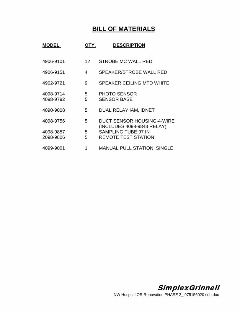
MODEL QTY. DESCRIPTION 4906-9101 12 STROBE MC WALL RED 4906-9151 4 SPEAKER/STROBE WALL RED
4902-9721 9 SPEAKER CEILING MTD WHITE
4098-9714 5 PHOTO SENSOR 4098-9792 5 SENSOR BASE 4090-9008 5 DUAL RELAY IAM, IDNET 4098-9756 5 DUCT SENSOR HOUSING-4-WIRE (INCLUDES 4098-9843 RELAY) 4098-9857 5 SAMPLING TUBE 97 IN 2098-9806 5 REMOTE TEST STATION 4099-9001 1 MANUAL PULL STATION, SINGLE

SimplexGrinnell NW Hospital OR Renovation PHASE 2_ 975156020 sub.doc
SECTION 3
Features
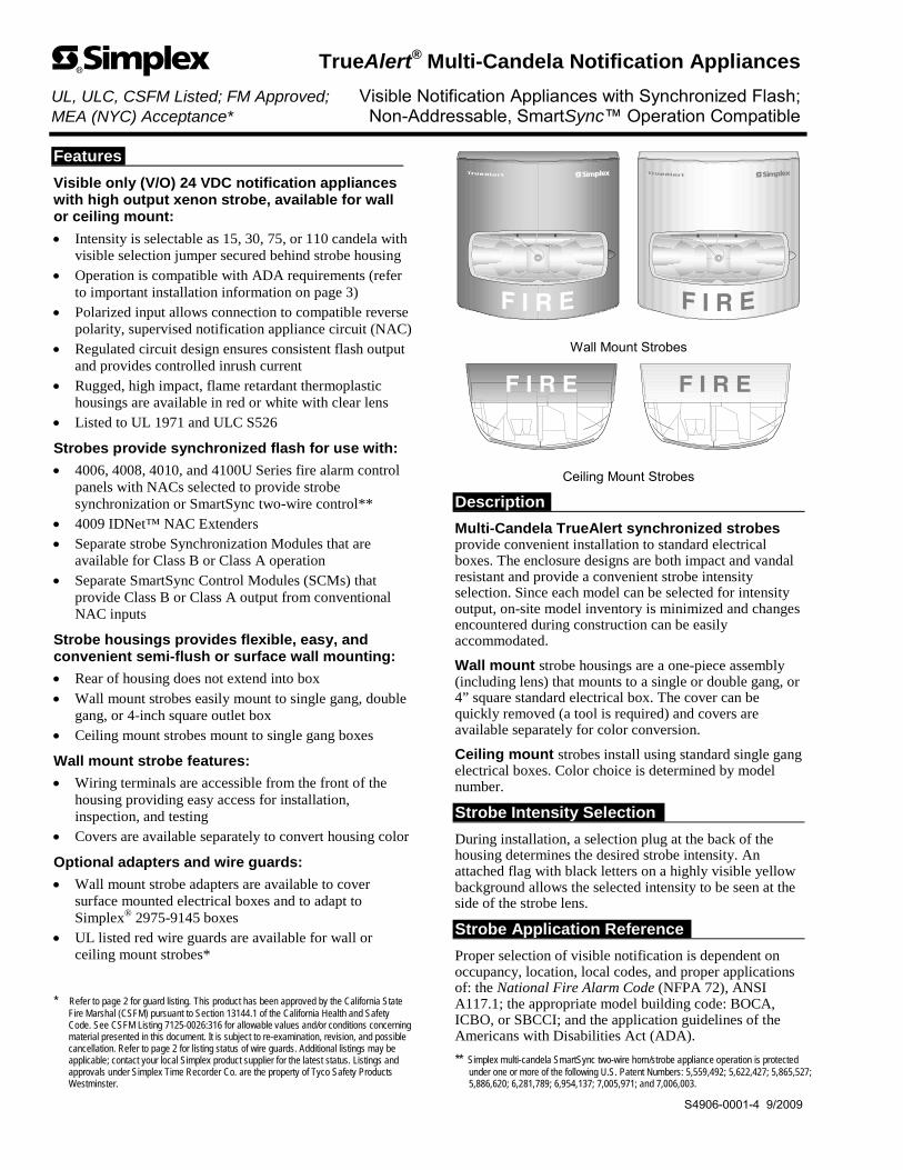
Visible only (V/O) 24 VDC notification appliances with high output xenon strobe, available for wall or ceiling mount:
Intensity is selectable as 15, 30, 75, or 110 candela with visible selection jumper secured behind strobe housing
Operation is compatible with ADA requirements (refer to important installation information on page 3)
Polarized input allows connection to compatible reverse polarity, supervised notification appliance circuit (NAC)
Regulated circuit design ensures consistent flash output and provides controlled inrush current
Rugged, high impact, flame retardant thermoplastic housings are available in red or white with clear lens
Listed to UL 1971 and ULC S526
Strobes provide synchronized flash for use with:
4006, 4008, 4010, and 4100U Series fire alarm control panels with NACs selected to provide strobe synchronization or SmartSync two-wire control**
4009 IDNet™ NAC Extenders Separate strobe Synchronization Modules that are
available for Class B or Class A operation Separate SmartSync Control Modules (SCMs) that
provide Class B or Class A output from conventional NAC inputs
Strobe housings provides flexible, easy, and convenient semi-flush or surface wall mounting:
Rear of housing does not extend into box
Wall mount strobes easily mount to single gang, double gang, or 4-inch square outlet box
Ceiling mount strobes mount to single gang boxes
Wall mount strobe features:
Wiring terminals are accessible from the front of the housing providing easy access for installation, inspection, and testing
Covers are available separately to convert housing color
Optional adapters and wire guards:
Wall mount strobe adapters are available to cover surface mounted electrical boxes and to adapt to Simplex® 2975-9145 boxes
UL listed red wire guards are available for wall or ceiling mount strobes*
* Refer to page 2 for guard listing. This product has been approved by the California State Fire Marshal (CSFM) pursuant to Section 13144.1 of the California Health and Safety Code. See CSFM Listing 7125-0026:316 for allowable values and/or conditions concerning material presented in this document. It is subject to re-examination, revision, and possible cancellation. Refer to page 2 for listing status of wire guards. Additional listings may be applicable; contact your local Simplex product supplier for the latest status. Listings and approvals under Simplex Time Recorder Co. are the property of Tyco Safety Products Westminster.
Wall Mount Strobes
Ceiling Mount Strobes
Description
Multi-Candela TrueAlert synchronized strobes provide convenient installation to standard electrical boxes. The enclosure designs are both impact and vandal resistant and provide a convenient strobe intensity selection. Since each model can be selected for intensity output, on-site model inventory is minimized and changes encountered during construction can be easily accommodated.
Wall mount strobe housings are a one-piece assembly (including lens) that mounts to a single or double gang, or 4” square standard electrical box. The cover can be quickly removed (a tool is required) and covers are available separately for color conversion.
Ceiling mount strobes install using standard single gang electrical boxes. Color choice is determined by model number.
Strobe Intensity Selection
During installation, a selection plug at the back of the housing determines the desired strobe intensity. An attached flag with black letters on a highly visible yellow background allows the selected intensity to be seen at the side of the strobe lens.
Strobe Application Reference
Proper selection of visible notification is dependent on occupancy, location, local codes, and proper applications of: the National Fire Alarm Code (NFPA 72), ANSI A117.1; the appropriate model building code: BOCA, ICBO, or SBCCI; and the application guidelines of the Americans with Disabilities Act (ADA).
** Simplex multi-candela SmartSync two-wire horn/strobe appliance operation is protected under one or more of the following U.S. Patent Numbers: 5,559,492; 5,622,427; 5,865,527; 5,886,620; 6,281,789; 6,954,137; 7,005,971; and 7,006,003.
TrueAlert® Multi-Candela Notification Appliances UL, ULC, CSFM Listed; FM Approved; Visible Notification Appliances with Synchronized Flash; MEA (NYC) Acceptance* Non-Addressable, SmartSync™ Operation Compatible
S4906-0001-4 9/2009
Synchronized Strobes
Multiple Strobes. When multiple strobes and their reflections can be seen from one location, synchronized flashes reduce the probability of photo-sensitive reactions as well as the annoyance and possible distraction of random flashing. These multi-candela strobes are synchronized over a two-wire circuit when connected to compatible NACs, to compatible Synchronized Flash Modules, or to SmartSync Control Modules.
SmartSync Two-Wire Control
Some applications desire the audible notification appliances to be capable of being silenced before the alarm condition is reset (on-until-silenced) while the visible notification appliances are kept activated until the alarm condition is reset (on-until-reset). SmartSync operation mode provides this function using a single circuit (two-wire operation).
SmartSync Control Sources
SmartSync two-wire control is available from:
4006, 4008, 4100U, and 4010 Fire Alarm Control Panels (refer to individual product data sheets for more information)
4009 IDNet NAC Extenders (refer to data sheet S4009-0002)
SmartSync Control Module (SCM) Model 4905-9938 (refer to data sheet S4905-0003)
Additional SmartSync compatible notification appliances include separate horns and combination horn/strobe notification appliances.
2 S4906-0001-4 9/2009
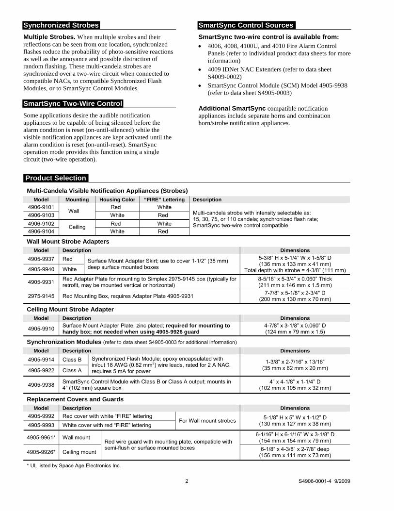
Multi-Candela Visible Notification Appliances (Strobes)
Model Mounting Housing Color “FIRE” Lettering Description
4906-9101 Red White
4906-9103 Wall
White Red
4906-9102 Red White
4906-9104 Ceiling
White Red
Multi-candela strobe with intensity selectable as: 15, 30, 75, or 110 candela; synchronized flash rate; SmartSync two-wire control compatible
Wall Mount Strobe Adapters
Model Description Dimensions
4905-9937 Red
4905-9940 White
Surface Mount Adapter Skirt; use to cover 1-1/2” (38 mm) deep surface mounted boxes
5-3/8” H x 5-1/4” W x 1-5/8” D (136 mm x 133 mm x 41 mm)
Total depth with strobe = 4-3/8” (111 mm)
4905-9931 Red Adapter Plate for mounting to Simplex 2975-9145 box (typically for retrofit, may be mounted vertical or horizontal)
8-5/16” x 5-3/4” x 0.060” Thick (211 mm x 146 mm x 1.5 mm)
2975-9145 Red Mounting Box, requires Adapter Plate 4905-9931 7-7/8" x 5-1/8" x 2-3/4" D
(200 mm x 130 mm x 70 mm)
Ceiling Mount Strobe Adapter
Model Description Dimensions
4905-9910 Surface Mount Adapter Plate; zinc plated; required for mounting to handy box; not needed when using 4905-9926 guard
4-7/8” x 3-1/8” x 0.060” D (124 mm x 79 mm x 1.5)
Synchronization Modules (refer to data sheet S4905-0003 for additional information)
Model Description Dimensions
4905-9914 Class B
4905-9922 Class A
Synchronized Flash Module; epoxy encapsulated with in/out 18 AWG (0.82 mm2) wire leads, rated for 2 A NAC, requires 5 mA for power
1-3/8” x 2-7/16” x 13/16” (35 mm x 62 mm x 20 mm)
4905-9938 SmartSync Control Module with Class B or Class A output; mounts in 4” (102 mm) square box
4” x 4-1/8” x 1-1/4” D (102 mm x 105 mm x 32 mm)
Replacement Covers and Guards
Model Description Dimensions
4905-9992 Red cover with white “FIRE” lettering
4905-9993 White cover with red “FIRE” lettering For Wall mount strobes
5-1/8” H x 5” W x 1-1/2” D (130 mm x 127 mm x 38 mm)
4905-9961* Wall mount 6-1/16” H x 6-1/16” W x 3-1/8” D
(154 mm x 154 mm x 79 mm)
4905-9926* Ceiling mount
Red wire guard with mounting plate, compatible with semi-flush or surface mounted boxes 6-1/8” x 4-3/8” x 2-7/8” deep
(156 mm x 111 mm x 73 mm)
* UL listed by Space Age Electronics Inc.
Product Selection
chbennett
Oval
3 S4906-0001-4 9/2009
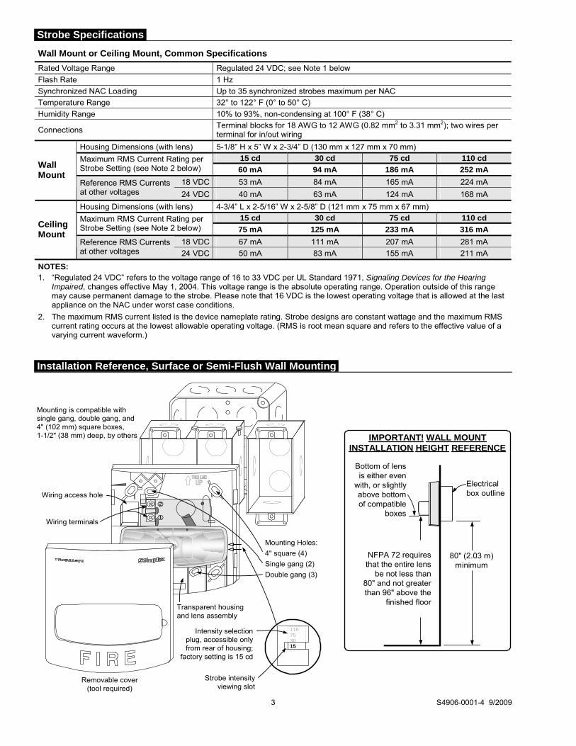
Wall Mount or Ceiling Mount, Common Specifications
Rated Voltage Range Regulated 24 VDC; see Note 1 below
Flash Rate 1 Hz
Synchronized NAC Loading Up to 35 synchronized strobes maximum per NAC
Temperature Range 32° to 122° F (0° to 50° C)
Humidity Range 10% to 93%, non-condensing at 100° F (38° C)
Connections Terminal blocks for 18 AWG to 12 AWG (0.82 mm2 to 3.31 mm2); two wires per terminal for in/out wiring
Housing Dimensions (with lens) 5-1/8” H x 5” W x 2-3/4” D (130 mm x 127 mm x 70 mm)
15 cd 30 cd 75 cd 110 cd Maximum RMS Current Rating per Strobe Setting (see Note 2 below) 60 mA 94 mA 186 mA 252 mA
18 VDC 53 mA 84 mA 165 mA 224 mA
Wall Mount
Reference RMS Currents at other voltages 24 VDC 40 mA 63 mA 124 mA 168 mA
Housing Dimensions (with lens) 4-3/4” L x 2-5/16” W x 2-5/8” D (121 mm x 75 mm x 67 mm)
15 cd 30 cd 75 cd 110 cd Maximum RMS Current Rating per Strobe Setting (see Note 2 below) 75 mA 125 mA 233 mA 316 mA
18 VDC 67 mA 111 mA 207 mA 281 mA
Ceiling Mount
Reference RMS Currents at other voltages 24 VDC 50 mA 83 mA 155 mA 211 mA
NOTES: 1. “Regulated 24 VDC” refers to the voltage range of 16 to 33 VDC per UL Standard 1971, Signaling Devices for the Hearing
Impaired, changes effective May 1, 2004. This voltage range is the absolute operating range. Operation outside of this range may cause permanent damage to the strobe. Please note that 16 VDC is the lowest operating voltage that is allowed at the last appliance on the NAC under worst case conditions.
2. The maximum RMS current listed is the device nameplate rating. Strobe designs are constant wattage and the maximum RMS current rating occurs at the lowest allowable operating voltage. (RMS is root mean square and refers to the effective value of a varying current waveform.)
Removable cover(tool required)
Mounting is compatible withsingle gang, double gang, and4" (102 mm) square boxes,1-1/2" (38 mm) deep, by others
2
1
Mounting Holes:
4" square (4)
Single gang (2)
Double gang (3)
Wiring access hole
Wiring terminals
Transparent housingand lens assembly
Strobe intensityviewing slot
Intensity selectionplug, accessible onlyfrom rear of housing;
factory setting is 15 cd
110753015
IMPORTANT! WALL MOUNTINSTALLATION HEIGHT REFERENCE
a
NFPA 72 requiresthat the entire lens
be not less than80" and not greaterthan 96" above the
finished floor
Electricalbox outline
80" (2.03 m)minimum
Bottom of lensis either even
with, or slightlyabove bottomof compatible
boxes
Installation Reference, Surface or Semi-Flush Wall Mounting
Strobe Specifications

Tyco Safety Products Westminster • Westminster, MA • 01441-0001 • USA S4906-0001-4 9/2009
www.tycosafetyproducts-usa-wm.com © 2009 Tyco Safety Products Westminster. All rights reserved. All specifications and other information shown were current as of document revision date and are subject to change without notice.
Tyco is a registered trademark of Tyco International Services GmbH and is used under license. Simplex, the Simplex logo, IDNet, TrueAlert, and SmartSync are trademarks of Tyco International Ltd. and its affiliates and are used under license. NFPA 72 and National Fire Alarm Code are registered trademarks of the National Fire Protection Association (NFPA).
Surface Mounting Referencewith Optional Adapter Skirtand Optional Wire Guard
2975-9145 Box
4905-9931 Adapter Plate
4905-9961 Optional Wire Guard(shown here for reference only,can be used on other mounting options)
4905-9931 Adapter Plate
4" (102 mm) squarebox profile, 1-1/2"
(38 mm) deep
Surface mount conduit andbox shown for reference
Strobe
Optional4905-9961
Wire Guard
Optional Surface Mount Adapter Skirt,1-1/2" deep: 4905-9937, Red;
4905-9940, White (conduit knockoutsare provided on all four sides)
110
75 30 15
4905-9910 Adapter Plate, required forsurface mount with handy box unlessusing the 4905-9926 wire guard
Handy box, 1-1/2" ( 38 mm) deep(RACO 650 or equal) or single gangbox, 2-1/2" (64 mm) deep (RACO 519or equal) supplied by others
Also can be attached to boxesmounted to drop ceiling T-bar withclips (ERICO No. 512 or equal)
Single gang box (WiremoldV5744S) 2-1/4" (57 mm)deep, supplied by others
Ceiling mount strobe
Optional 4905-9926 wire guardwith mounting plate
Strobe intensityviewing slot
Intensity selection plug,accessible only from rear of lenshousing; factory setting is 15 cd
Wall Mount Installation Reference; Adapter Plate, Guard, and Adapter Skirt
Ceiling Mount Strobe Installation Reference
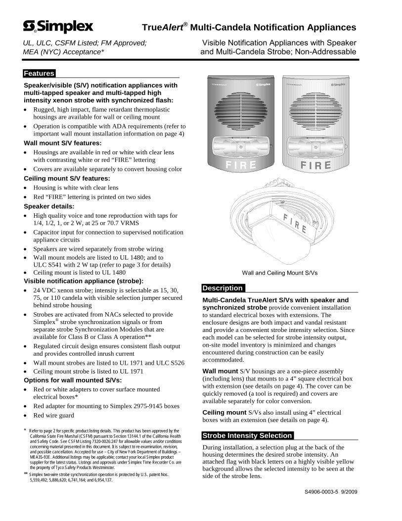
Features
Speaker/visible (S/V) notification appliances with multi-tapped speaker and multi-tapped high intensity xenon strobe with synchronized flash:
Rugged, high impact, flame retardant thermoplastic housings are available for wall or ceiling mount
Operation is compatible with ADA requirements (refer to important wall mount installation information on page 4)
Wall mount S/V features:
Housings are available in red or white with clear lens with contrasting white or red “FIRE” lettering
Covers are available separately to convert housing color
Ceiling mount S/V features:
Housing is white with clear lens
Red “FIRE” lettering is printed on two sides
Speaker details:
High quality voice and tone reproduction with taps for 1/4, 1/2, 1, or 2 W, at 25 or 70.7 VRMS
Capacitor input for connection to supervised notification appliance circuits
Speakers are wired separately from strobe wiring Wall mount models are listed to UL 1480; and to
ULC S541 with 2 W tap (refer to page 3 for details) Ceiling mount is listed to UL 1480 Visible notification appliance (strobe):
24 VDC xenon strobe; intensity is selectable as 15, 30, 75, or 110 candela with visible selection jumper secured behind strobe housing
Strobes are activated from NACs selected to provide Simplex® strobe synchronization signals or from separate strobe Synchronization Modules that are available for Class B or Class A operation**
Regulated circuit design ensures consistent flash output and provides controlled inrush current
Wall mount strobes are listed to UL 1971 and ULC S526 Ceiling mount strobe is listed to UL 1971 Options for wall mounted S/Vs:
Red or white adapters to cover surface mounted electrical boxes*
Red adapter for mounting to Simplex 2975-9145 boxes
Red wire guard * Refer to page 2 for specific product listing details. This product has been approved by the
California State Fire Marshal (CSFM) pursuant to Section 13144.1 of the California Health and Safety Code. See CSFM Listing 7320-0026:247 for allowable values and/or conditions concerning material presented in this document. It is subject to re-examination, revision, and possible cancellation. Accepted for use – City of New York Department of Buildings – MEA35-93E. Additional listings may be applicable; contact your local Simplex product supplier for the latest status. Listings and approvals under Simplex Time Recorder Co. are the property of Tyco Safety Products Westminster.
** Simplex two-wire strobe synchronization operation is protected by U.S. patent Nos. 5,559,492; 5,886,620; 6,741,164; and 6,954,137.
Wall and Ceiling Mount S/Vs
Description
Multi-Candela TrueAlert S/Vs with speaker and synchronized strobe provide convenient installation to standard electrical boxes with extensions. The enclosure designs are both impact and vandal resistant and provide a convenient strobe intensity selection. Since each model can be selected for strobe intensity output, on-site model inventory is minimized and changes encountered during construction can be easily accommodated.
Wall mount S/V housings are a one-piece assembly (including lens) that mounts to a 4” square electrical box with extension (see details on page 4). The cover can be quickly removed (a tool is required) and covers are available separately for color conversion.
Ceiling mount S/Vs also install using 4” electrical boxes with an extension (see details on page 4).
Strobe Intensity Selection
During installation, a selection plug at the back of the housing determines the desired strobe intensity. An attached flag with black letters on a highly visible yellow background allows the selected intensity to be seen at the side of the strobe lens.
TrueAlert® Multi-Candela Notification Appliances UL, ULC, CSFM Listed; FM Approved; Visible Notification Appliances with Speaker MEA (NYC) Acceptance* and Multi-Candela Strobe; Non-Addressable
S4906-0003-5 9/2009

Synchronized Strobes
Multiple Strobes. When multiple strobes and their reflections can be seen from one location, synchronized flashes reduce the probability of photo-sensitive reactions as well as the annoyance and possible distraction of random flashing. The multi-candela strobes of these S/Vs are activated by NACs that provide the Simplex synchronization format. For additional information, refer to data sheet S4905-0003.
Strobe Application Selection
Proper selection of visible notification is dependent on occupancy, location, local codes, and proper applications of: the National Fire Alarm Code (NFPA 72), ANSI A117.1; the appropriate model building code: BOCA, ICBO, or SBCCI; and the application guidelines of the Americans with Disabilities Act (ADA).
2 S4906-0003-5 9/2009
Wall Mount Multi-Candela S/Vs
Model Housing
Color “FIRE”
Lettering Description Housing Dimensions with Lens
4906-9151 Red White
4906-9153 White Red
Multi-tapped Speaker with Multi-Candela Synchronized Strobe; strobe intensity selectable as: 15, 30, 75, or 110 candela
7-1/4” H x 5” W x 2-5/8” D (184 mm x 127 mm x 67 mm)
Ceiling Mount Multi-Candela S/V (not ULC listed)
Model Housing
Color “FIRE”
Lettering Description Dimensions
4906-9154 White Red Multi-tapped Speaker with Multi-Candela Synchronized Strobe; strobe intensity selectable as: 15, 30, 75, or 110 candela
Housing = 7-1/2” (191 mm) diameter, 1/2” (13 mm) deep Strobe lens protrusion = 2-5/8” (67 mm) above speaker housing Depth into box = 2-3/4” (70 mm)
Wall Mount S/V Adapters
Model Description Dimensions
4905-9946 Surface mount red adapter skirt
4905-9947 Surface mount white adapter skirt
Required when mounting to surface mounted electrical box, 4” square, 1-1/2” deep with 1-1/2” deep extension (not ULC listed)
7-3/4” H x 5-3/8” W x 3-3/16” D (197 mm x 137 mm x 81 mm)
depth with S/V = 5-7/8” (149 mm)
4905-9903 Adapter Plate, red, required to mount S/V on 2975-9145 8-5/16" H x 5-3/4" W x 0.060” Thick(211 mm x 146 mm x 1.5 mm)
2975-9145 Mounting box, red, for surface or flush mount, requires adapter plate 4905-9903 (this box may be available for retrofit applications)
7-7/8" H x 5-1/8" W x 2-3/4" D (200 mm x 130 mm x 70 mm)
Wall Mount S/V Replacement Covers
Model Description Dimensions
4905-9996 Red S/V cover with white “FIRE” lettering
4905-9997 White S/V cover with red “FIRE” lettering
7-1/4” H x 5” W x 1-3/8” D (184 mm x 127 mm x 35 mm)
Synchronized Flash Control Modules
Model Description Dimensions
4905-9914* Synchronized Flash Module, Class B (Style Y) operation
4905-9922* Synchronized Flash Module, Class A (Style Z) operation
Epoxy encapsulated with in/out 18 AWG (0.82 mm2) wire leads, rated for 2 A NAC, requires 5 mA for power
1-3/8” W x 2-7/16” L x 13/16” H (35 mm x 62 mm x 20 mm)
Wall Mount S/V Wire Guard
Model Description Dimensions
4905-9998 Wire guard with mounting plate, red, compatible with surface and semi-flush boxes (UL listed by Space Age Electronics Inc.)
8-3/8” H x 6-1/16” W x 3-1/4” D (213 mm x 154 mm x 79 mm)
Ceiling Mount Tile Bridge
Model Description Dimensions
2905-9946 Tile Bridge See diagram on page 4
* Refer to data sheet S4905-0003 for additional flash control module information
Product Selection
chbennett
Oval

3 S4906-0003-5 9/2009
Common Specifications
Environmental; Temperature and Humidity 32° to 122° F (0° to 50° C); 10% to 93%, non-condensing at 100° F (38° C)
Connections Terminal blocks for 18 AWG to 12 AWG (0.82 mm2 to 3.31 mm2 ); two wires per terminal for in/out wiring
Speaker Specifications
Input Voltage 25 or 70.7 VRMS, see Note 1 below
Power Taps 1/4, 1/2, 1, and 2 W
Fire Alarm 400 to 4000 Hz Frequency Response
General Signaling 125 to 12 kHz
Wattage Tap 1/4 W 1/2 W 1 W 2 W*
All Models, Reverberant Chamber Test, per UL 1480 @ 10 ft (~3 m) 76 dBA 79 dBA 82 dBA 85 dBA
Speaker Output Ratings
Wall mount models only, Anechoic Chamber Test, per ULC S541 @ 3 m (~10 ft) 77 dBA 80 dBA 83 dBA 86 dBA
Attenuation Angle Attenuation Angle All Models, Speaker Polar Dispersion Reference (per ULC S541 Anechoic Chamber Testing) -3 dB +/- 30° off-axis -6 dB +/- 55° off-axis
* NOTE: ULC Fire Alarm applications require use of 2 W tap.
Strobe Specifications
Rated Voltage Range Regulated 24 VDC; see Note 2 below
Flash Rate and Synchronized NAC Loading 1 Hz; with up to 35 synchronized strobes maximum per NAC
Housing Dimensions (with lens) 7-1/4” H x 5” W x 2-5/8” D (184 mm x 127 mm x 67 mm)
15 cd 30 cd 75 cd 110 cd Maximum RMS Current Rating per Strobe Setting (see Note 3 below) 60 mA 94 mA 186 mA 252 mA
18 VDC 53 mA 84 mA 165 mA 224 mA
Wall Mount
Reference RMS Currents at other voltages 24 VDC 40 mA 63 mA 124 mA 168 mA
Housing Dimensions Speaker housing = 7-1/2” (191 mm) diameter, 1/2” deep (13 mm); lens protrusion above speaker housing = 2-5/8” (67 mm); depth into box = 2-3/4” (70 mm)
15 cd 30 cd 75 cd 110 cd Maximum RMS Current Rating per Strobe Setting (see Note 3 below) 75 mA 125 mA 233 mA 316 mA
18 VDC 67 mA 111 mA 207 mA 281 mA
Ceiling Mount
Reference RMS Currents at other voltages 24 VDC 50 mA 83 mA 155 mA 211 mA
NOTES:
1. Speakers are for connection to conventional fire alarm audio circuits.
2. “Regulated 24 VDC” refers to the voltage range of 16 to 33 VDC per UL Standard 1971, Signaling Devices for the Hearing Impaired, changes effective May 1, 2004. This voltage range is the absolute operating range. Operation outside of this range may cause permanent damage to the appliance. Please note that 16 VDC is the lowest operating voltage that is allowed at the last appliance on the NAC under worst case conditions.
3. The maximum RMS strobe current listed is the device nameplate rating. Strobe designs are constant wattage and the maximum RMS current rating occurs at the lowest allowable operating voltage. (RMS is root mean square and refers to the effective value of a varying current waveform.)
S/V Specifications

Tyco Safety Products Westminster • Westminster, MA • 01441-0001 • USA S4906-0003-5 9/2009
www.tycosafetyproducts-usa-wm.com © 2009 Tyco Safety Products Westminster. All rights reserved. All specifications and other information shown were current as of document revision date and are subject to change without notice.
Tyco is a registered trademark of Tyco International Services GmbH and is used under license. Simplex, the Simplex logo, and TrueAlert are trademarks of Tyco International Ltd. and its affiliates and are used under license. NFPA 72 and National Fire Alarm Code are registered trademarks of the National Fire Protection Association (NFPA).
Standard Electrical Box MountingMounting to 2975-9145 Box
4905-9903Adapter Plate
2975-9145 Box
Transparenthousing andlens assembly
Wiring input terminals andspeaker tap selection areaccessible from rear
Speaker assembly
Strobe assembly
Removable cover(tool required)
4" (102 mm) square box, 1-1/2"(38 mm) deep, with a 4" square box
extension, 1-1/2" deep, by others
Strobe intensityviewing slot
Intensity selectionplug, accessible onlyfrom rear of housing;
factory setting is 15 cd
110753015
110
75 30 15
4" (102 mm) square, 1-1/2"(38 mm) deep box with 1-1/2"extension (by others)
Wiring input terminals andspeaker tap selection areaccessible from rear ofspeaker housing
Strobe intensityviewing slot
Intensity selection plug,accessible only from rear of lenshousing; factory setting is 15 cd
13-3/8" (340 mm)
1/4" diameter (6mm) holes, 4 places
0.024" thick sheetmetal, folded with1/2" lip each side
3-3/4" (95 mm) squarecutout, centered on plate
23-11/16" (602 mm)
6-11/16"(170 mm)
1/2" (13 mm)2905-9946Tile Bridge
IMPORTANT ! INSTALLATIONMOUNTING HEIGHT REFERENCE
NFPA 72 requires that theentire lens be not less than80" and not greater than 96"above the finished floor.
4" square box outline
4" (102 mm)
1-1/2" (38 mm)82" (2.1 m)minimum
78-1/2" (2 m)minimum
2975-9145box outline
CL
4" (102 mm) square boxprofile, 1-1/2" (38 mm)
deep with 1-1/2" extension
Surface mount conduit andbox shown for reference
S/V
Optional 4905-9998Wire Guard
Surface mount adapter skirt, 3-3/16" (81 mm)deep, required for this mounting method:
4905-9946, Red; 4905-9947, White (conduitknockouts are provided on all four sides)
Surface Mounting ReferenceShowing Optional Wire Guard
Wall Mount Installation Reference (Adapter Skirts are Not ULC listed)
Ceiling Mount S/V Installation Reference and Tile Bridge Dimensions
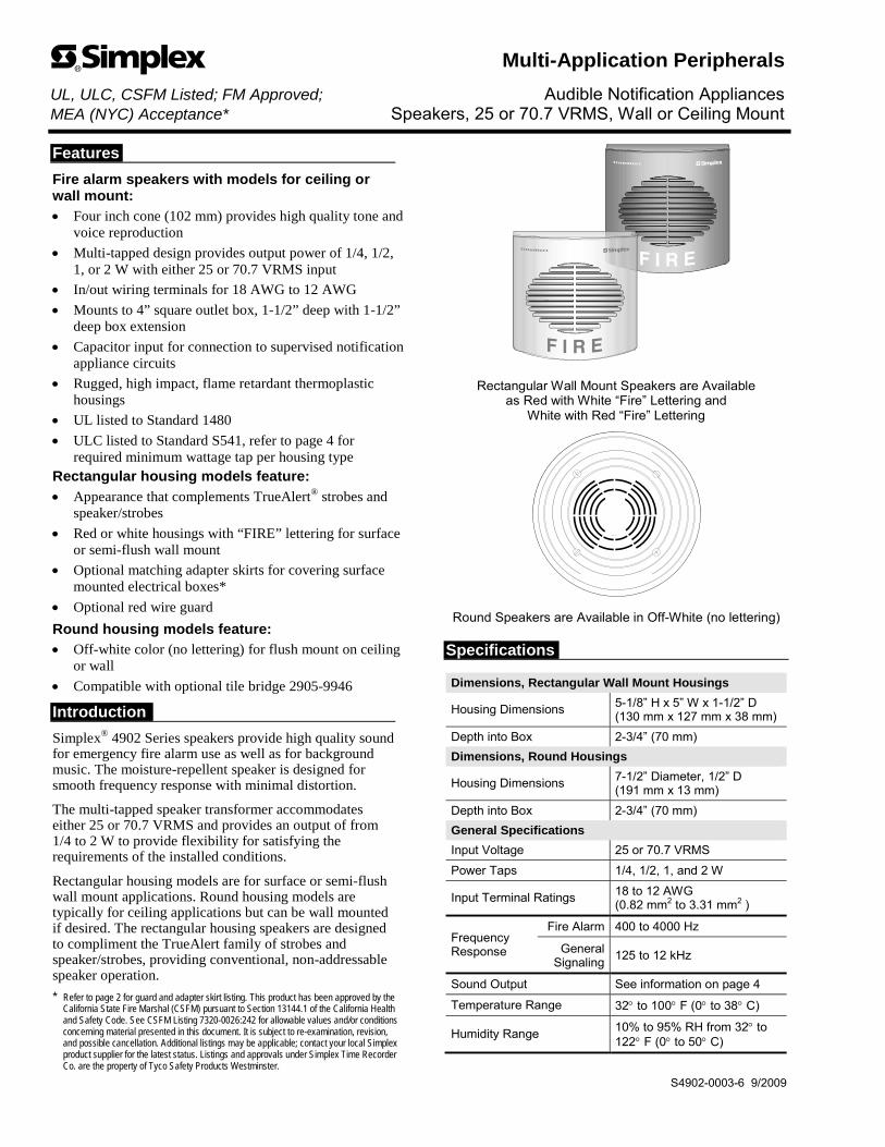
Features
Fire alarm speakers with models for ceiling or wall mount:
Four inch cone (102 mm) provides high quality tone and voice reproduction
Multi-tapped design provides output power of 1/4, 1/2, 1, or 2 W with either 25 or 70.7 VRMS input
In/out wiring terminals for 18 AWG to 12 AWG
Mounts to 4” square outlet box, 1-1/2” deep with 1-1/2” deep box extension
Capacitor input for connection to supervised notification appliance circuits
Rugged, high impact, flame retardant thermoplastic housings
UL listed to Standard 1480
ULC listed to Standard S541, refer to page 4 for required minimum wattage tap per housing type
Rectangular housing models feature:
Appearance that complements TrueAlert® strobes and speaker/strobes
Red or white housings with “FIRE” lettering for surface or semi-flush wall mount
Optional matching adapter skirts for covering surface mounted electrical boxes*
Optional red wire guard
Round housing models feature:
Off-white color (no lettering) for flush mount on ceiling or wall
Compatible with optional tile bridge 2905-9946
Introduction
Simplex® 4902 Series speakers provide high quality sound for emergency fire alarm use as well as for background music. The moisture-repellent speaker is designed for smooth frequency response with minimal distortion.
The multi-tapped speaker transformer accommodates either 25 or 70.7 VRMS and provides an output of from 1/4 to 2 W to provide flexibility for satisfying the requirements of the installed conditions.
Rectangular housing models are for surface or semi-flush wall mount applications. Round housing models are typically for ceiling applications but can be wall mounted if desired. The rectangular housing speakers are designed to compliment the TrueAlert family of strobes and speaker/strobes, providing conventional, non-addressable speaker operation.
* Refer to page 2 for guard and adapter skirt listing. This product has been approved by the California State Fire Marshal (CSFM) pursuant to Section 13144.1 of the California Health and Safety Code. See CSFM Listing 7320-0026:242 for allowable values and/or conditions concerning material presented in this document. It is subject to re-examination, revision, and possible cancellation. Additional listings may be applicable; contact your local Simplex product supplier for the latest status. Listings and approvals under Simplex Time Recorder Co. are the property of Tyco Safety Products Westminster.
Rectangular Wall Mount Speakers are Available as Red with White “Fire” Lettering and
White with Red “Fire” Lettering
Round Speakers are Available in Off-White (no lettering) Specifications
Dimensions, Rectangular Wall Mount Housings
Housing Dimensions 5-1/8” H x 5” W x 1-1/2” D (130 mm x 127 mm x 38 mm)
Depth into Box 2-3/4” (70 mm)
Dimensions, Round Housings
Housing Dimensions 7-1/2” Diameter, 1/2” D (191 mm x 13 mm)
Depth into Box 2-3/4” (70 mm)
General Specifications
Input Voltage 25 or 70.7 VRMS
Power Taps 1/4, 1/2, 1, and 2 W
Input Terminal Ratings 18 to 12 AWG (0.82 mm2 to 3.31 mm2 )
Frequency Response
Fire Alarm 400 to 4000 Hz
General Signaling
125 to 12 kHz
Sound Output See information on page 4
Temperature Range 32 to 100 F (0 to 38 C)
Humidity Range 10% to 95% RH from 32 to 122 F (0 to 50 C)
Multi-Application Peripherals UL, ULC, CSFM Listed; FM Approved; Audible Notification Appliances MEA (NYC) Acceptance* Speakers, 25 or 70.7 VRMS, Wall or Ceiling Mount
S4902-0003-6 9/2009
2 S4902-0003-6 9/2009
Speakers
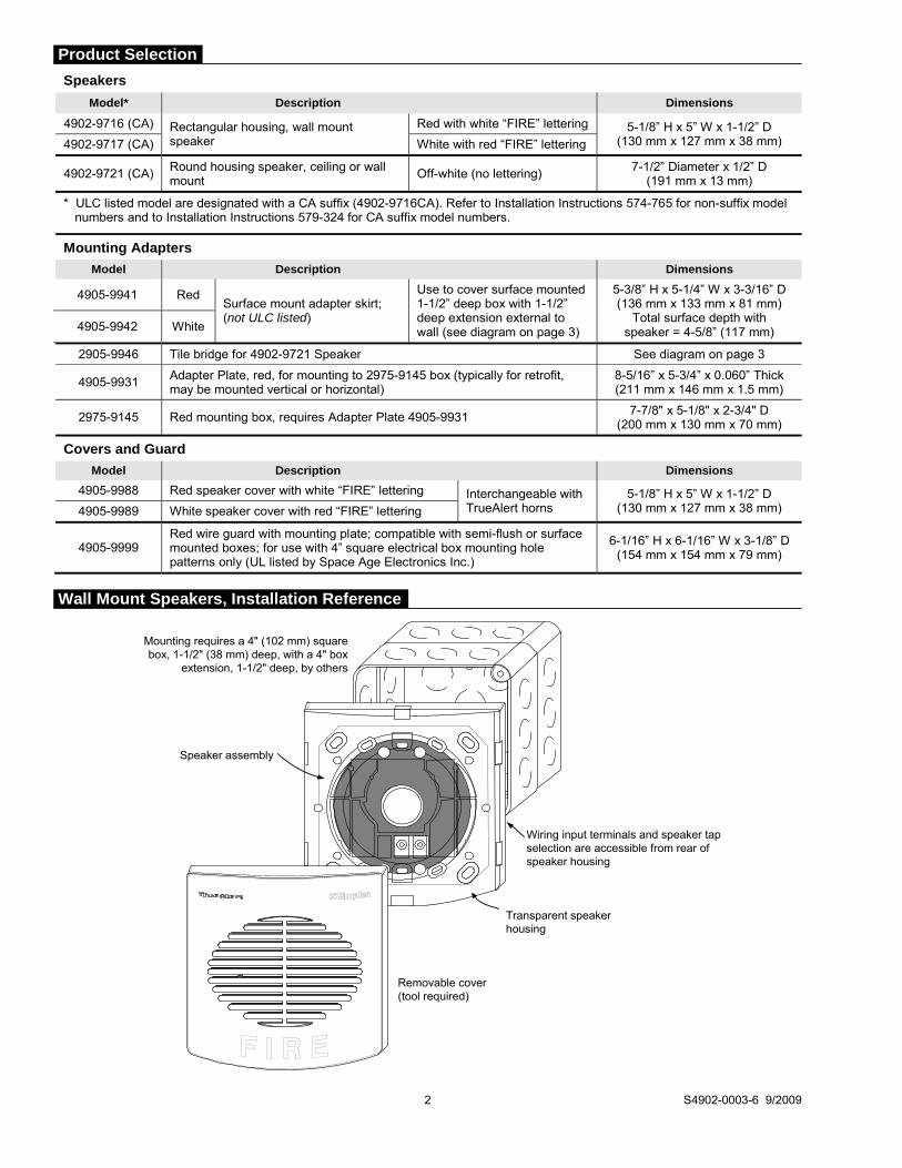
Model* Description Dimensions
4902-9716 (CA) Rectangular housing, wall mount speaker
Red with white “FIRE” lettering 5-1/8” H x 5” W x 1-1/2” D (130 mm x 127 mm x 38 mm) 4902-9717 (CA) White with red “FIRE” lettering
4902-9721 (CA) Round housing speaker, ceiling or wall mount
Off-white (no lettering) 7-1/2” Diameter x 1/2” D
(191 mm x 13 mm)
* ULC listed model are designated with a CA suffix (4902-9716CA). Refer to Installation Instructions 574-765 for non-suffix model numbers and to Installation Instructions 579-324 for CA suffix model numbers.
Mounting Adapters
Model Description Dimensions
4905-9941 Red Surface mount adapter skirt; (not ULC listed)
Use to cover surface mounted 1-1/2” deep box with 1-1/2” deep extension external to wall (see diagram on page 3)
5-3/8” H x 5-1/4” W x 3-3/16” D (136 mm x 133 mm x 81 mm)
Total surface depth with speaker = 4-5/8” (117 mm) 4905-9942 White
2905-9946 Tile bridge for 4902-9721 Speaker See diagram on page 3
4905-9931 Adapter Plate, red, for mounting to 2975-9145 box (typically for retrofit, may be mounted vertical or horizontal)
8-5/16” x 5-3/4” x 0.060” Thick (211 mm x 146 mm x 1.5 mm)
2975-9145 Red mounting box, requires Adapter Plate 4905-9931 7-7/8" x 5-1/8" x 2-3/4" D (200 mm x 130 mm x 70 mm)
Covers and Guard
Model Description Dimensions
4905-9988 Red speaker cover with white “FIRE” lettering Interchangeable with TrueAlert horns
5-1/8” H x 5” W x 1-1/2” D (130 mm x 127 mm x 38 mm) 4905-9989 White speaker cover with red “FIRE” lettering
4905-9999 Red wire guard with mounting plate; compatible with semi-flush or surface mounted boxes; for use with 4” square electrical box mounting hole patterns only (UL listed by Space Age Electronics Inc.)
6-1/16” H x 6-1/16” W x 3-1/8” D(154 mm x 154 mm x 79 mm)
Mounting requires a 4" (102 mm) squarebox, 1-1/2" (38 mm) deep, with a 4" box
extension, 1-1/2" deep, by others
Transparent speakerhousing
Wiring input terminals and speaker tapselection are accessible from rear ofspeaker housing
Removable cover(tool required)
Speaker assembly
Product Selection
Wall Mount Speakers, Installation Reference
chbennett
Oval

3 S4902-0003-6 9/2009
4" square, 1-1/2" deep boxwith 1-1/2" extension (by others)
Wiring input terminals and speaker tap selection are accessible from
rear of speaker housing
Front View
13-3/8"(340 mm)
6-11/16"(170 mm)
23-11/16" (602 mm)
1/2"(13 mm)
1/4" diameter (6 mm)holes, 4 places
0.024" thick sheetmetal, folded with1/2" lip each side
3-3/4" (95 mm) squarecutout, centered on plate
4" (102 mm) square boxextension, 1-1/2" (38 mm) deep
Surface mount adapter skirt, 3-3/16" deep:4905-9941, Red; 4905-9942, White
Speakerassembly
Wall surface
Conduit knockouts areprovided on all four sides
4" (102 mm) square box, 1-1/2" (38 mm) deep with conduit shown for reference
Optional 4905-9999 Wire Guard
Round Speaker Installation Reference (typically ceiling mount, can be wall mounted)
2905-9946 Tile Bridge Dimensions
Surface Mounted Speaker Reference (Adapter Skirts are Not ULC listed)

Sound Output Ratings @ 10 ft (~3 m) per UL 1480 Reverberant Chamber Testing
Model Type Input Voltage Selected Tap
1/4 W 1/2 W 1 W 2 W
4902-9716 4902-9717
Rectangular Housing 25 VRMS 80 dBA 83 dBA 85 dBA 88 dBA
70.7 VRMS 79 dBA 82 dBA 85 dBA 88 dBA
4902-9721 Round Housing 25 or 70.7 VRMS 79 dBA 82 dBA 85 dBA 88 dBA
Sound Output Ratings @ 3 m (~10 ft) per ULC S541 Anechoic Chamber Testing
Model Type Input Voltage Selected Tap
1/4 W 1/2 W 1 W*
(see note) 2 W*
(see note)
4902-9716CA 4902-9717CA
Rectangular Housing* 25 VRMS or 70.7 VRMS 77 dBA 80 dBA 83 dBA 86 dBA
4902-9721CA Round Housing* 25 VRMS or 70.7 VRMS 79 dBA 82 dBA 85 dBA 89 dBA
* NOTE: ULC Fire Alarm applications require use of 1 W or 2 W tap for Round Housing speakers; and 2 W tap for Rectangular Housing speakers.
Speaker Polar Dispersion Reference (per ULC S541 Anechoic Chamber Testing)
Attenuation Angle
-3 dB 30° off-axis
-6 dB 55° off-axis
Speaker assembly
2975-9145 Box
4905-9931 Adapter Plate
4905-9931 Adapter Plate
4905-9999 OptionalWire Guard
(shown here forreference only, can
be used on othermounting options)
Tyco Safety Products Westminster • Westminster, MA • 01441-0001 • USA S4902-0003-6 9/2009
www.tycosafetyproducts-usa-wm.com © 2009 Tyco Safety Products Westminster. All rights reserved. All specifications and other information shown were current as of document revision date and are subject to change without notice.
Tyco is a registered trademark of Tyco International Services GmbH and is used under license. Simplex, the Simplex logo, and TrueAlert are trademarks of Tyco International Ltd. and its affiliates and are used under license.
Speaker Sound Output Specifications
4905-9931 Adapter Plate Installation Reference

Features
TrueAlarm analog sensing provides: Digital transmission of analog sensor values via IDNet
or MAPNET II two-wire communications
For use with the following Simplex® products: 4100ES, 4100U, 4010ES, and 4010 Series control
panels; and 4008 Series control panels with reduced feature set (refer to data sheet S4008-0001 for details)
4020, 4100, and 4120 Series control panels, Universal Transponders, and 2120 TrueAlarm CDTs equipped for MAPNET II operation
Fire alarm control panel provides: Peak value logging allowing accurate analysis of each
sensor for individual sensitivity selection
Sensitivity monitoring satisfying NFPA 72 sensitivity testing requirements; automatic individual sensor calibration check verifies sensor integrity
Automatic environmental compensation, multi-stage alarm operation, and display of sensitivity directly in percent per foot
Ability to display and print detailed sensor information in plain English language
Photoelectric smoke sensors provide: Seven levels of sensitivity from 0.2% to 3.7%
(refer to additional information on page 3)
Heat sensors provide: Fixed temperature sensing
Rate-of-rise temperature sensing
Utility temperature sensing
Listed to UL 521 and ULC-S530
General features: Listed to UL 268 and ULC-S529
Louvered smoke sensor design enhances smoke capture by directing flow to chamber; entrance areas are minimally visible when ceiling mounted
Designed for EMI compatibility
Magnetic test feature is provided
Optional accessories include remote LED alarm indicator and output relays
Additional base reference: For isolator bases, refer to data sheet S4098-0025
For sounder bases, refer to data sheet S4098-0028
For photo/heat sensors, refer to data sheet S4098-0024 (single address) and S4098-0033 (dual address)
* These products have been approved by the California State Fire Marshal (CSFM) pursuant to Section 13144.1 of the California Health and Safety Code. See CSFM Listings 7272-0026:218, 7271-0026:231, 7270-0026:216, and 7300-0026:217 for allowable values and/or conditions concerning material presented in this document. Accepted for use – City of New York Department of Buildings – MEA35-93E. Additional listings may be applicable, contact your local Simplex product supplier for the latest status. Listings and approvals under Simplex Time Recorder Co. are the property of Tyco Fire Protection Products.
4098-9714 TrueAlarm Photoelectric Sensor Mounted in Base
Description
Digital Communication of Analog Sensing. TrueAlarm analog sensors provide an analog measurement digitally communicated to the host control panel using Simplex addressable communications. At the control panel, the data is analyzed and an average value is determined and stored. An alarm or other abnormal condition is determined by comparing the sensor’s present value against its average value and time.
Intelligent Data Evaluation. Monitoring each sensor’s average value provides a continuously shifting reference point. This software filtering process compensates for environmental factors (dust, dirt, etc.) and component aging, providing an accurate reference for evaluating new activity. With this filtering, there is a significant reduction in the probability of false or nuisance alarms caused by shifts in sensitivity, either up or down.
Control Panel Selection. Peak activity per sensor is stored to assist in evaluating specific locations. The alarm set point for each TrueAlarm sensor is determined at the host control panel, selectable as more or less sensitive as the individual application requires.
Timed/Multi-Stage Selection. Sensor alarm set points can be programmed for timed automatic sensitivity selection (such as more sensitive at night, less sensitive during day). Control panel programming can also provide multi-stage operation per sensor. For example, a 0.2% level may cause a warning to prompt investigation while a 2.5% level may initiate an alarm.
Sensor Alarm and Trouble LED Indication. Each sensor base’s LED pulses to indicate communications with the panel. If the control panel determines a sensor is in alarm, or is dirty or has some other type of trouble, the details are annunciated at the control panel and that sensor base’s LED will be turned on steadily. During a system alarm, the control panel will control the LEDs such that an LED indicating a trouble will return to pulsing to help identify the alarmed sensors.
TrueAlarm Analog Sensing UL, ULC, CSFM Listed; FM Approved; TrueAlarm Analog Sensors – Photoelectric MEA (NYC) Acceptance* and Heat; Standard Bases and Accessories
S4098-0019-15 4/2013
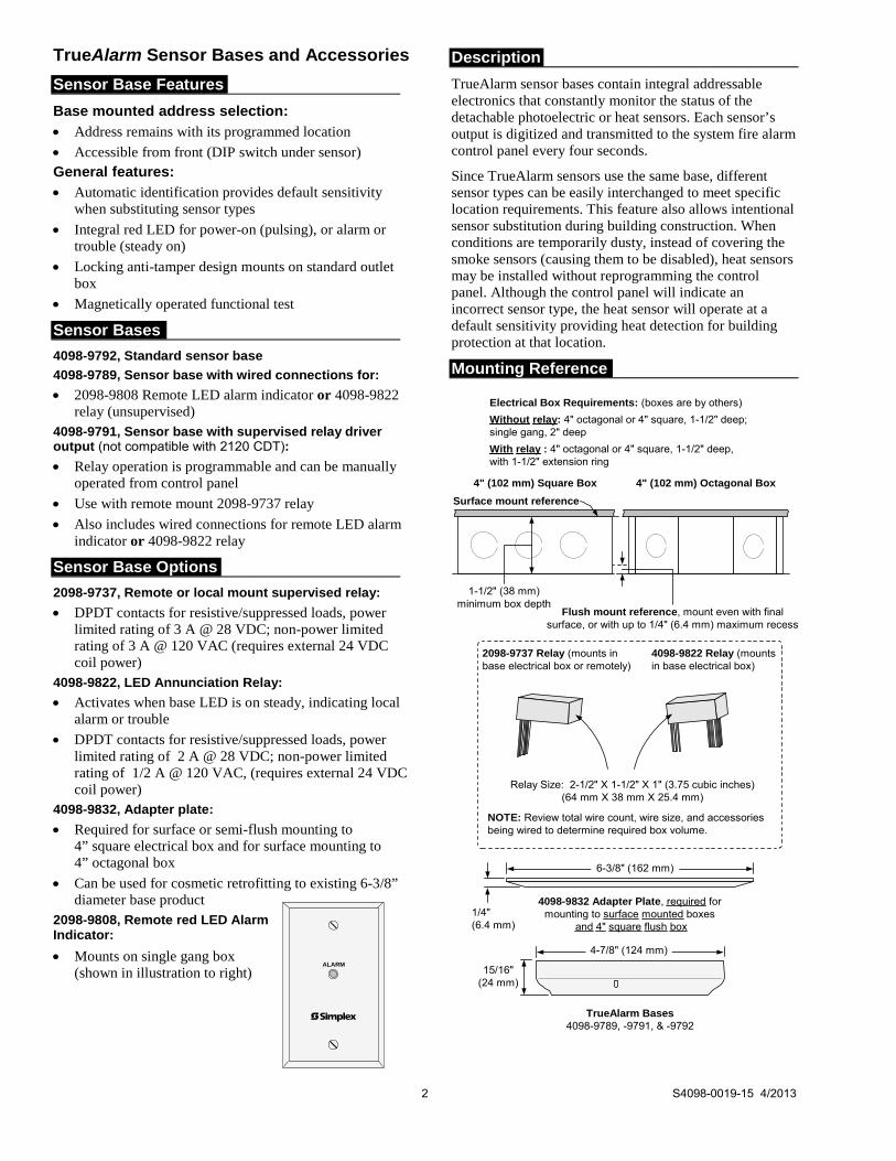
Sensor Base Features
Base mounted address selection:
Address remains with its programmed location
Accessible from front (DIP switch under sensor) General features:
Automatic identification provides default sensitivity when substituting sensor types
Integral red LED for power-on (pulsing), or alarm or trouble (steady on)
Locking anti-tamper design mounts on standard outlet box
Magnetically operated functional test
Sensor Bases
4098-9792, Standard sensor base
4098-9789, Sensor base with wired connections for:
2098-9808 Remote LED alarm indicator or 4098-9822 relay (unsupervised)
4098-9791, Sensor base with supervised relay driver output (not compatible with 2120 CDT):
Relay operation is programmable and can be manually operated from control panel
Use with remote mount 2098-9737 relay
Also includes wired connections for remote LED alarm indicator or 4098-9822 relay
Sensor Base Options
2098-9737, Remote or local mount supervised relay:
DPDT contacts for resistive/suppressed loads, power limited rating of 3 A @ 28 VDC; non-power limited rating of 3 A @ 120 VAC (requires external 24 VDC coil power)
4098-9822, LED Annunciation Relay:
Activates when base LED is on steady, indicating local alarm or trouble
DPDT contacts for resistive/suppressed loads, power limited rating of 2 A @ 28 VDC; non-power limited rating of 1/2 A @ 120 VAC, (requires external 24 VDC coil power)
4098-9832, Adapter plate:
Required for surface or semi-flush mounting to 4” square electrical box and for surface mounting to 4” octagonal box
Can be used for cosmetic retrofitting to existing 6-3/8” diameter base product
2098-9808, Remote red LED Alarm Indicator:
Mounts on single gang box (shown in illustration to right)
Description
TrueAlarm sensor bases contain integral addressable electronics that constantly monitor the status of the detachable photoelectric or heat sensors. Each sensor’s output is digitized and transmitted to the system fire alarm control panel every four seconds.
Since TrueAlarm sensors use the same base, different sensor types can be easily interchanged to meet specific location requirements. This feature also allows intentional sensor substitution during building construction. When conditions are temporarily dusty, instead of covering the smoke sensors (causing them to be disabled), heat sensors may be installed without reprogramming the control panel. Although the control panel will indicate an incorrect sensor type, the heat sensor will operate at a default sensitivity providing heat detection for building protection at that location.
Mounting Reference
Electrical Box Requirements: (boxes are by others)
Without relay: 4" octagonal or 4" square, 1-1/2" deep;single gang, 2" deep
With relay : 4" octagonal or 4" square, 1-1/2" deep,with 1-1/2" extension ring
TrueAlarm Bases4098-9789, -9791, & -9792
4-7/8" (124 mm)
15/16"(24 mm)
6-3/8" (162 mm)
1/4"(6.4 mm)
4098-9832 Adapter Plate, required formounting to surface mounted boxes
and 4" square flush box
Surface mount reference
4" (102 mm) Square Box 4" (102 mm) Octagonal Box
Flush mount reference, mount even with finalsurface, or with up to 1/4" (6.4 mm) maximum recess
2098-9737 Relay (mounts inbase electrical box or remotely)
4098-9822 Relay (mountsin base electrical box)
Relay Size: 2-1/2" X 1-1/2" X 1" (3.75 cubic inches)(64 mm X 38 mm X 25.4 mm)
NOTE: Review total wire count, wire size, and accessoriesbeing wired to determine required box volume.
1-1/2" (38 mm)minimum box depth
2 S4098-0019-15 4/2013
TrueAlarm Sensor Bases and Accessories
ALARM
TrueAlarm Sensors
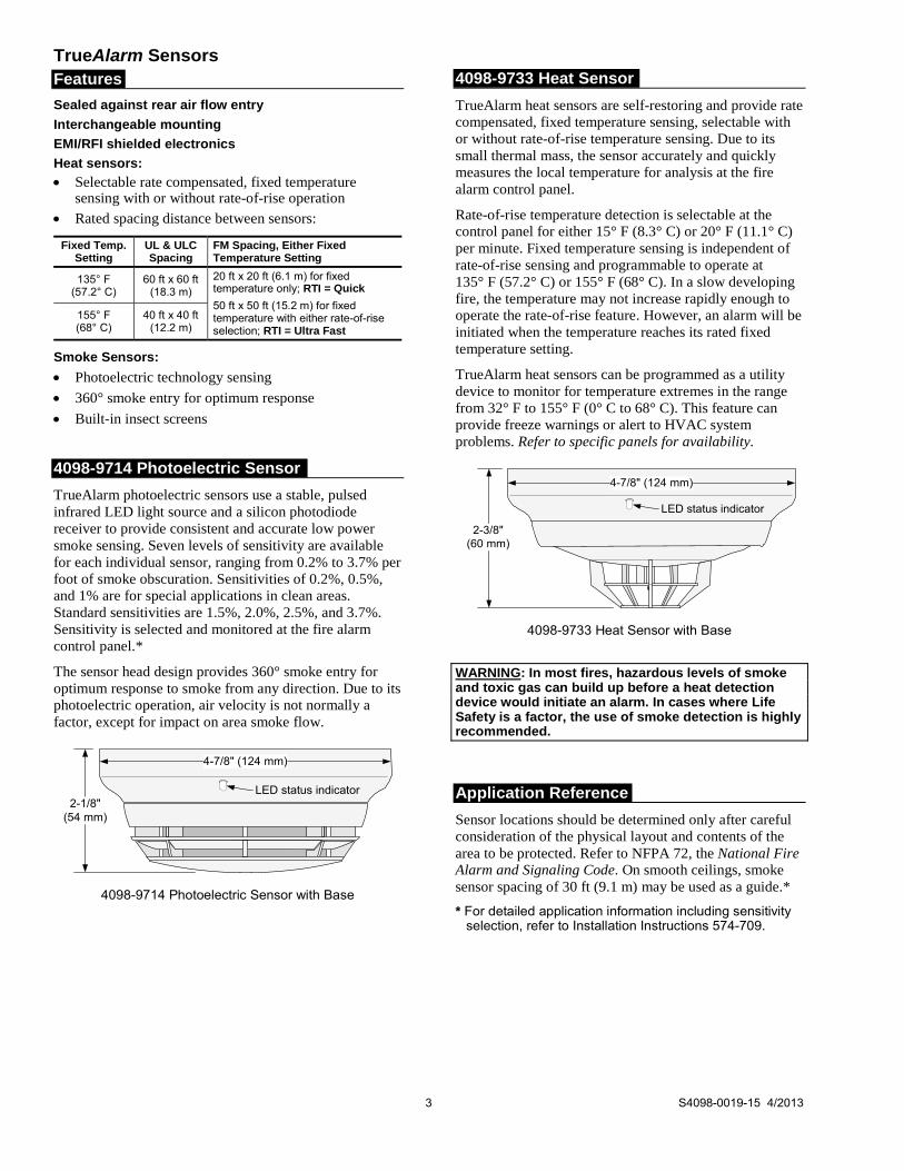
Features
Sealed against rear air flow entry
Interchangeable mounting
EMI/RFI shielded electronics
Heat sensors:
Selectable rate compensated, fixed temperature sensing with or without rate-of-rise operation
Rated spacing distance between sensors:
Fixed Temp. Setting
UL & ULC Spacing
FM Spacing, Either Fixed Temperature Setting
135° F (57.2° C)
60 ft x 60 ft (18.3 m)
20 ft x 20 ft (6.1 m) for fixed temperature only; RTI = Quick
50 ft x 50 ft (15.2 m) for fixed temperature with either rate-of-rise selection; RTI = Ultra Fast
155° F (68° C)
40 ft x 40 ft (12.2 m)
Smoke Sensors:
Photoelectric technology sensing
360° smoke entry for optimum response
Built-in insect screens
4098-9714 Photoelectric Sensor
TrueAlarm photoelectric sensors use a stable, pulsed infrared LED light source and a silicon photodiode receiver to provide consistent and accurate low power smoke sensing. Seven levels of sensitivity are available for each individual sensor, ranging from 0.2% to 3.7% per foot of smoke obscuration. Sensitivities of 0.2%, 0.5%, and 1% are for special applications in clean areas. Standard sensitivities are 1.5%, 2.0%, 2.5%, and 3.7%. Sensitivity is selected and monitored at the fire alarm control panel.*
The sensor head design provides 360° smoke entry for optimum response to smoke from any direction. Due to its photoelectric operation, air velocity is not normally a factor, except for impact on area smoke flow.
2-1/8"(54 mm)
LED status indicator
4-7/8" (124 mm)
4098-9714 Photoelectric Sensor with Base
4098-9733 Heat Sensor
TrueAlarm heat sensors are self-restoring and provide rate compensated, fixed temperature sensing, selectable with or without rate-of-rise temperature sensing. Due to its small thermal mass, the sensor accurately and quickly measures the local temperature for analysis at the fire alarm control panel.
Rate-of-rise temperature detection is selectable at the control panel for either 15° F (8.3° C) or 20° F (11.1° C) per minute. Fixed temperature sensing is independent of rate-of-rise sensing and programmable to operate at 135° F (57.2° C) or 155° F (68° C). In a slow developing fire, the temperature may not increase rapidly enough to operate the rate-of-rise feature. However, an alarm will be initiated when the temperature reaches its rated fixed temperature setting.
TrueAlarm heat sensors can be programmed as a utility device to monitor for temperature extremes in the range from 32° F to 155° F (0° C to 68° C). This feature can provide freeze warnings or alert to HVAC system problems. Refer to specific panels for availability.
2-3/8"(60 mm)
LED status indicator
4-7/8" (124 mm)
4098-9733 Heat Sensor with Base
WARNING: In most fires, hazardous levels of smoke and toxic gas can build up before a heat detection device would initiate an alarm. In cases where Life Safety is a factor, the use of smoke detection is highly recommended.
Application Reference
Sensor locations should be determined only after careful consideration of the physical layout and contents of the area to be protected. Refer to NFPA 72, the National Fire Alarm and Signaling Code. On smooth ceilings, smoke sensor spacing of 30 ft (9.1 m) may be used as a guide.*
* For detailed application information including sensitivity selection, refer to Installation Instructions 574-709.
3 S4098-0019-15 4/2013

TrueAlarm Sensor Bases (Refer to Application Manual 574-709 and Installation Instructions 574-707 for additional information)
Model Description Compatibility Mounting Requirements
4098-9792 Standard Sensor Base, no options Sensors 4098-9714 and 4098-9733 4” octagonal or 4” square box, 1-1/2” min. depth; or single gang box, 2” min. depth
4098-9789 Sensor Base with connections for Remote LED Alarm Indicator or Unsupervised Relay
Sensors 4098-9714 and 4098-9733 4” octagonal or 4” square box
Note: Box depth requirements depend on total wire count and wire size, refer to accessories list below for reference.
** NOTE: 4098-9791 is NOT compatible with the 2120 CDT
2098-9808 remote LED alarm indicator or 4098-9822 relay
4098-9791**
Sensor Base with connections for Supervised Remote Relay and connections for Remote Alarm Indicator or Unsupervised Relay
Sensors 4098-9714 and 4098-9733
2098-9737 remote relay (supervised)
2098-9808 remote alarm indicator or 4098-9822 relay (unsupervised)
TrueAlarm Sensors Model Description Compatibility Mounting Requirements
4098-9714 Photoelectric Smoke Sensor Bases 4098-9792, 4098-9789, and 4098-9791
Refer to base requirements 4098-9733 Heat Sensor
TrueAlarm Sensor/Base Accessories Model Description Compatibility Mounting Requirements
2098-9737 Supervised Relay, mounts remote or in base electrical box
For use with 4098-9791 base
Remote Mounting requires 4” octagonal or 4” square box, 1-1/2” minimum depth Base Mounting requires 4” octagonal box, 2-1/8” deep with 1-1/2” extension ring
2098-9808 Remote Red LED Alarm Indicator on single gang stainless steel plate
Bases 4098-9789 and 4098-9791
Single gang box, 1-1/2” minimum depth
4098-9822 Relay, tracks base LED status (unsupervised, mounts only in base electrical box)
4” octagonal box, 2-1/8” deep with 1-1/2” extension ring
4098-9832 Adapter Plate Bases 4098-9792, -9789, & -9791 Required for surface or semi-flush mounted 4” square box and for surface mounted 4” octagonal box
TYCO, SIMPLEX, and the product names listed in this material are marks and/or registered marks. Unauthorized use is strictly prohibited. NFPA 72 and National Fire Alarm and Signaling Code are trademarks of the National Fire Protection Association (NFPA).
Tyco Fire Protection Products • Westminster, MA • 01441-0001 • USA S4098-0019-15 4/2013
www.simplexgrinnell.com © 2013 Tyco Fire Protection Products. All rights reserved. All specifications and other information shown were current as of document revision date and are subject to change without notice.
General Operating Specifications
Communications and Sensor Supervisory Power MAPNET II or IDNet, auto-select, 24-40 VDC w/data, 400 A typical, 1 address per base
Communications Connections Screw terminals for in/out wiring, 18 to 14 AWG (0.82 mm2 to 2.08 mm2)
Remote LED Alarm Indicator Current 1 mA typical, no impact to alarm current
Remote LED Alarm Indicator and Relay Connections Color coded wire leads, 18 AWG (0.82 mm2 )
UL Listed Temperature Range 32° to 100° F (0° to 38° C)
Operating Temperature Range with 4098 -9733 32° to 122° F (0° to 50° C)
with 4098-9714 15° to 122° F (-9° to 50° C)
Humidity Range 10 to 95% RH
Smoke Sensor Ambient Ratings
4098-9714, Photoelectric Sensor
Air velocity = 0-4000 ft/min (0-1220 m/min)
Housing Color Frost White
4098-9791 Base With Supervised Remote Relay 2098-9737 (see page 2 for contact ratings)
Externally Supplied Relay Coil Voltage 18-32 VDC (nominal 24 VDC)
Supervisory Current 270 A, from 24 VDC supply
Alarm Current with 2098-9737 Relay 28 mA, from 24 VDC supply
4098-9822 Unsupervised Relay, Requirements for Bases 4098-9789 and 4098-9791 (see page 2 for contact ratings) Externally Supplied Relay Coil Voltage 18-32 VDC (nominal 24 VDC)
Supervisory Current Supplied from communications
Alarm Current 13 mA from separate 24 VDC supply
TrueAlarm Analog Sensing Product Selection Chart
Specifications
chbennett
Oval
chbennett
Oval

Features
Individual Addressable Dual Contact Relay Module (Dual Relay IAM): A single addressable point provides control and status
tracking of two, 2 A Form “C” contacts Low power latching relay design allows IDNet or
MAPNET II communications to supply both data and module power
For use with following Simplex control panels: Model Series 4100ES, 4010ES, 4100U, and 4010 fire
alarm control panels for IDNet communications Model Series 4100/4100U/4100ES, 4120, 4020, and
2120 Communicating Device Transponders (CDTs) equipped with MAPNET II communications
Compact construction: Mounts in standard 4” (102 mm) square electrical box,
optional adapter bracket is available to mount in a 4 11⁄16” square electrical box
Screw terminals for wiring connections Visible LED flashes to indicate communications, can be
selected at panel to indicate activated state Optional 4” square box covers are available to allow
LED to be viewed after installation
UL listed to Standard 864
Description
Dual Relay IAMs allow fire alarm control panels to control two remotely located Form “C” contact using IDNet or MAPNET II addressable communications for both data and module power. Typical applications would be for switching local power for control functions such as elevator capture, or control of HVAC components, pressurization fans, dampers, etc. Relay status is also communicated requiring only one device address.
Product Selection
Model Description
4090-9008 Dual Relay IAM
Optional Adapter Plates
Model Description
4090-9813 Adapter plate to fit 4 11⁄16” (119 mm) square electrical box
4090-9801 For semi-flush mounted box
Optional trim plate for 4” boxes with LED viewing window, includes mounting screws; galvanized steel 4090-9802
For surface mounted box
* This product has been approved by the California State Fire Marshal (CSFM) pursuant to
Section 13144.1 of the California Health and Safety Code. See CSFM Listing 7300-0026:0311 for allowable values and/or conditions concerning material presented in this document. Additional listings may be applicable; contact your local Simplex product supplier for the latest status. Listings and approvals under Simplex Time Recorder Co. are the property of Tyco Safety Products Westminster.
NO
C N
C
CO
MM
-+
NO
C N
C
REM
OVE THIS SIDE FIRST
ON
OFF
2 AM
P F
US
E
2 AM
P F
US
E
4090-9008 Dual Relay IAM (shown approximately 1/2 size)
Specifications
Communications IDNet or MAPNET II communications, 1 address per device
Power Supplied by communications
Installation Instructions
579-1040
Contact Ratings* (not rated for incandescent switching)
Type Dual Form C contacts (DPDT) with terminal block access to Common, N.O., and N.C for each contact
Power-Limited 2 A @ 30 VDC, resistive from listed
fire alarm supply 1 A @ 30 VDC, inductive
Nonpower-Limited 0.5 A @ 125 VAC, resistive
Relay Fusing Each contact common is fused with a 2 A fast acting non-time delay fuse
* Provide external transient suppression as required per application. DC inductive loads can typically be diode suppressed; 120 VAC loads may require RC networks or varistors, depending on device type. Refer to Installation Instructions for additional information.
Wire Connections Screw terminals for in/out wiring, 18 to 14 AWG wire (0.82 to 2.08 mm2)
IDNet or MAPNET II Communications Wiring Reference
Up to 2500 ft ( 762 m) from control panel
Up to 10,000 ft ( 3048 m) total wiring distance (including T-Taps)
Compatible with Simplex 2081-9044 Overvoltage Protectors
Dimensions 4 ⅛” H x 4” W x 1 ⅜” D (105 mm x 102 mm x 35 mm)
Mounting Plate Sheet metal, galvanized
Temperature Range
32° to 120° F (0° to 49° C), intended for indoor operation
Humidity Range Up to 93% RH at 100° F (38° C)
Addressable Initiation Peripherals UL, ULC, CSFM Listed; IDNet and MAPNET II Communicating Devices FM Approved* Model 4090-9008 Dual Contact Relay IAM
S4090-0014 8/2013
chbennett
Oval
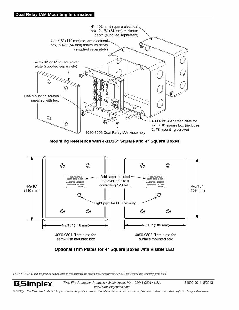
Optional Trim Plates for 4" Square Boxes with Visible LED
4090-9802, Trim plate forsurface mounted box
4090-9801, Trim plate forsemi-flush mounted box
4-9/16"(116 mm)
4-9/16" (116 mm)
4-5/16"(109 mm)
Light pipe for LED viewing
4-5/16" (109 mm)
Mounting Reference with 4-11/16" Square and 4" Square Boxes
4090-9008 Dual Relay IAM Assembly
4090-9813 Adapter Plate for 4-11/16" square box (includes 2, #8 mounting screws)
4-11/16" (119 mm) square electrical box, 2-1/8" (54 mm) minimum depth
(supplied separately)
4" (102 mm) square electrical box, 2-1/8" (54 mm) minimum
depth (supplied separately)
4-11/16" or 4" square cover plate (supplied separately)
Use mounting screws supplied with box
Add supplied label to cover on-site if
controlling 120 VAC
Tyco Fire Protection Products • Westminster, MA • 01441-0001 • USA S4090-0014 8/2013
www.simplexgrinnell.com © 2013 Tyco Fire Protection Products. All rights reserved. All specifications and other information shown were current as of document revision date and are subject to change without notice.
TYCO, SIMPLEX, and the product names listed in this material are marks and/or registered marks. Unauthorized use is strictly prohibited.
Dual Relay IAM Mounting Information
Features
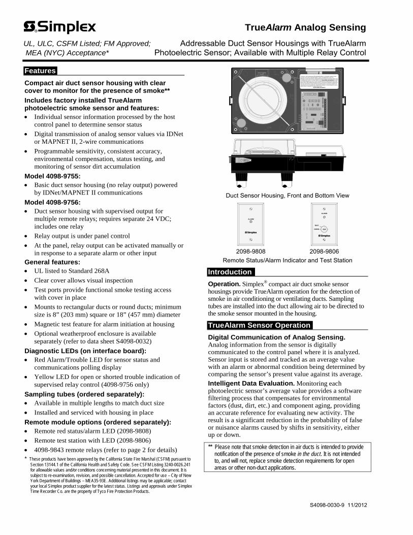
Compact air duct sensor housing with clear cover to monitor for the presence of smoke**
Includes factory installed TrueAlarm photoelectric smoke sensor and features: Individual sensor information processed by the host
control panel to determine sensor status
Digital transmission of analog sensor values via IDNet or MAPNET II, 2-wire communications
Programmable sensitivity, consistent accuracy, environmental compensation, status testing, and monitoring of sensor dirt accumulation
Model 4098-9755: Basic duct sensor housing (no relay output) powered
by IDNet/MAPNET II communications
Model 4098-9756: Duct sensor housing with supervised output for
multiple remote relays; requires separate 24 VDC; includes one relay
Relay output is under panel control
At the panel, relay output can be activated manually or in response to a separate alarm or other input
General features: UL listed to Standard 268A
Clear cover allows visual inspection
Test ports provide functional smoke testing access with cover in place
Mounts to rectangular ducts or round ducts; minimum size is 8” (203 mm) square or 18” (457 mm) diameter
Magnetic test feature for alarm initiation at housing
Optional weatherproof enclosure is available separately (refer to data sheet S4098-0032)
Diagnostic LEDs (on interface board): Red Alarm/Trouble LED for sensor status and
communications polling display
Yellow LED for open or shorted trouble indication of supervised relay control (4098-9756 only)
Sampling tubes (ordered separately): Available in multiple lengths to match duct size
Installed and serviced with housing in place
Remote module options (ordered separately): Remote red status/alarm LED (2098-9808)
Remote test station with LED (2098-9806)
4098-9843 remote relays (refer to page 2 for details) * These products have been approved by the California State Fire Marshal (CSFM) pursuant to
Section 13144.1 of the California Health and Safety Code. See CSFM Listing 3240-0026.241 for allowable values and/or conditions concerning material presented in this document. It is subject to re-examination, revision, and possible cancellation. Accepted for use – City of New York Department of Buildings – MEA35-93E. Additional listings may be applicable; contact your local Simplex product supplier for the latest status. Listings and approvals under Simplex Time Recorder Co. are the property of Tyco Fire Protection Products.
This device is a duct smoke housing. When provided with detector, it is designed to sample the air flowpassing by it in the air duct to determine whether it contains unacceptable levels of smoke. Theeffectiveness of a duct smoke detector is highly dependent upon: the design and operating conditions of theair handling system in which it is installed, variables such as smoke dilution and stratification over whicheven the best designed systems have no control, and proper placement and positioning of the duct smokedetector, which is often compromised for practical reasons. For the reasons stated above, the effectivenessof this duct smoke detector cannot be warranted or guaranteed. Under no circumstances should this ductsmoke detector be used or regarded to be a substitute for the building's Fire alarm and detection system towhich this device is attached as a secondary detection device.
DO NOT REMOVE THIS NOTICE!
Duct Sensor Housing, Front and Bottom View
ALARM
TEST
NORM
ALARM
2098-9808 2098-9806
Remote Status/Alarm Indicator and Test Station
Introduction
Operation. Simplex® compact air duct smoke sensor housings provide TrueAlarm operation for the detection of smoke in air conditioning or ventilating ducts. Sampling tubes are installed into the duct allowing air to be directed to the smoke sensor mounted in the housing.
TrueAlarm Sensor Operation
Digital Communication of Analog Sensing. Analog information from the sensor is digitally communicated to the control panel where it is analyzed. Sensor input is stored and tracked as an average value with an alarm or abnormal condition being determined by comparing the sensor’s present value against its average.
Intelligent Data Evaluation. Monitoring each photoelectric sensor’s average value provides a software filtering process that compensates for environmental factors (dust, dirt, etc.) and component aging, providing an accurate reference for evaluating new activity. The result is a significant reduction in the probability of false or nuisance alarms caused by shifts in sensitivity, either up or down.
** Please note that smoke detection in air ducts is intended to provide notification of the presence of smoke in the duct. It is not intended to, and will not, replace smoke detection requirements for open areas or other non-duct applications.
TrueAlarm Analog Sensing UL, ULC, CSFM Listed; FM Approved; Addressable Duct Sensor Housings with TrueAlarm MEA (NYC) Acceptance* Photoelectric Sensor; Available with Multiple Relay Control
S4098-0030-9 11/2012
TrueAlarm Sensor Operation (Continued)
Control Panel Selection. Peak activity per sensor is stored to assist in evaluating specific locations. The alarm set point for each sensor is determined at the control panel, selectable as the individual application requires.
Sensor Status LED. Each sensor housing’s red status LED (located on the electrical interface board) pulses to indicate communications with the panel. If the control panel determines that a sensor is in alarm, or that it is dirty or has some other type of trouble, the details are annunciated at the control panel and that sensor housing’s status LED will be turned on steadily. During a system alarm, the control panel will control the LEDs such that an LED indicating a trouble will return to pulsing to help identify any alarmed sensors. (Remote Status/Alarm LEDs track the operation of the sensor housing LED.)
Photoelectric Sensing
TrueAlarm photoelectric sensors use a stable, pulsed infrared LED light source and a silicon photodiode receiver to provide consistent and accurate low power smoke sensing.
Photoelectric Sensing (Continued)
Typically duct sensor applications require less sensitive settings (such as 2.5% per foot obscuration) due to the ducts being a relative dirty environment. However, the standard seven levels of TrueAlarm sensor sensitivity are available for each individual sensor, ranging from 0.2% to 3.7% per foot of smoke obscuration. Sensitivity is selected and monitored at the fire alarm control panel.
Fire Alarm Control Panel Features
Individual smoke sensitivity selection Sensitivity monitoring that satisfies NFPA 72
sensitivity testing requirements Peak value logging allows accurate analysis for
sensitivity selection Automatic, once per minute individual sensor
calibration check verifies sensor integrity Automatic environmental compensation Smoke sensitivity is displayed in percent per foot Ability to display and print detailed sensor
information in plain English language Relays of model 4098-9756 are under panel control
for ON, OFF, or override
2 S4098-0030-9 11/2012
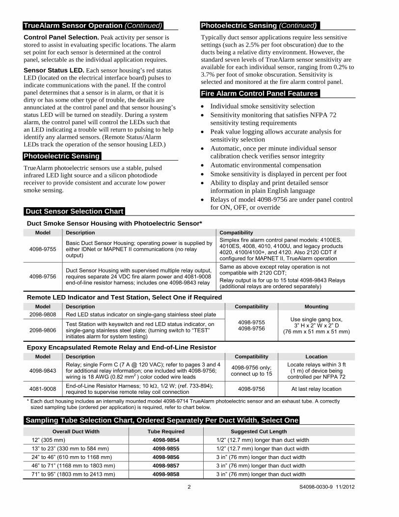
Duct Smoke Sensor Housing with Photoelectric Sensor* Model Description Compatibility
4098-9755 Basic Duct Sensor Housing; operating power is supplied by either IDNet or MAPNET II communications (no relay output)
Simplex fire alarm control panel models: 4100ES, 4010ES, 4008, 4010, 4100U, and legacy products 4020, 4100/4100+, and 4120. Also 2120 CDT if configured for MAPNET II, TrueAlarm operation
4098-9756 Duct Sensor Housing with supervised multiple relay output, requires separate 24 VDC fire alarm power and 4081-9008 end-of-line resistor harness; includes one 4098-9843 relay
Same as above except relay operation is not compatible with 2120 CDT; Relay output is for up to 15 total 4098-9843 Relays (additional relays are ordered separately)
Remote LED Indicator and Test Station, Select One if Required Model Description Compatibility Mounting
2098-9808 Red LED status indicator on single-gang stainless steel plate
4098-9755 4098-9756
Use single gang box, 3” H x 2” W x 2” D
(76 mm x 51 mm x 51 mm) 2098-9806 Test Station with keyswitch and red LED status indicator, on single-gang stainless steel plate; (turning switch to “TEST” initiates alarm for system testing)
Epoxy Encapsulated Remote Relay and End-of-Line Resistor Model Description Compatibility Location
4098-9843 Relay; single Form C (7 A @ 120 VAC); refer to pages 3 and 4 for additional relay information; one included with 4098-9756; wiring is 18 AWG (0.82 mm2 ) color coded wire leads
4098-9756 only; connect up to 15
Locate relays within 3 ft (1 m) of device being
controlled per NFPA 72
4081-9008 End-of-Line Resistor Harness; 10 k, 1/2 W; (ref. 733-894); required to supervise remote relay coil connection 4098-9756 At last relay location
* Each duct housing includes an internally mounted model 4098-9714 TrueAlarm photoelectric sensor and an exhaust tube. A correctly sized sampling tube (ordered per application) is required, refer to chart below.
Overall Duct Width Tube Required Suggested Cut Length
12” (305 mm) 4098-9854 1/2” (12.7 mm) longer than duct width
13” to 23” (330 mm to 584 mm) 4098-9855 1/2” (12.7 mm) longer than duct width
24” to 46” (610 mm to 1168 mm) 4098-9856 3 in” (76 mm) longer than duct width
46” to 71” (1168 mm to 1803 mm) 4098-9857 3 in” (76 mm) longer than duct width
71” to 95” (1803 mm to 2413 mm) 4098-9858 3 in” (76 mm) longer than duct width
Duct Sensor Selection Chart
Sampling Tube Selection Chart, Ordered Separately Per Duct Width, Select One
chbennett
Oval
chbennett
Oval
chbennett
Oval
chbennett
Oval
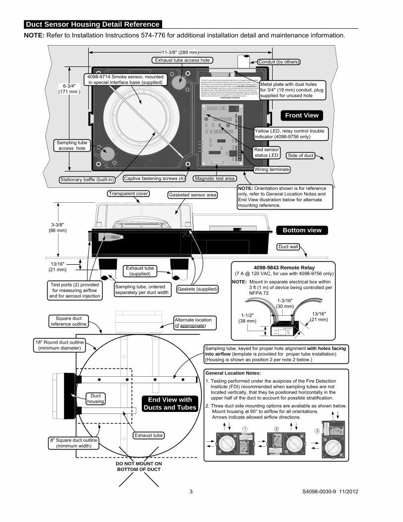
NOTE: Refer to Installation Instructions 574-776 for additional installation detail and maintenance information.
3 S4098-0030-9 11/2012
This device is a duct smoke housing. When provided with detector, it is designed to sample the air flow passing by it in the air duct to determine whether it contains unacceptable levels of smoke. The effectiveness of a duct smoke detector is highly dependent upon: the design and operating conditions of the air handling system in which it is installed, variables such as smoke dilution and stratification over which even the best designed systems have no control, and proper placement and positioning of the duct smoke detector, which is often compromised for practical reasons. For the reasons stated above, the effectiveness of this duct smoke detector cannot be warranted or guaranteed. Under no circumstances should this duct smoke detector be used or regarded to be a substitute for the building's Fire alarm and detection system to which this device is attached as a secondary detection device.
DO NOT REMOVE THIS NOTICE!
6-3/4"(171 mm )
11-3/8" (289 mm)
3-3/8"(86 mm)
Exhaust tube access hole
Captive fastening screws (4)
Metal plate with dual holes for 3/4" (19 mm) conduit, plug supplied for unused hole
Wiring terminals
Gaskets (supplied)
Conduit (by others)
Stationary baffle (built-in)
4098-9714 Smoke sensor, mounted in special interface base (supplied)
Magnetic test area
Test ports (2) provided for measuring airflow
and for aerosol injection
13/16" (21 mm)
Sampling tube, ordered separately per duct width
Exhaust tube (supplied)
NOTE: Orientation shown is for reference only, refer to General Location Notes and End View illustration below for alternate mounting reference.
Red sensor status LED
Transparent cover Gasketed sensor area
Sampling tube access hole
Duct wall
Front View
Bottom view
Yellow LED, relay control trouble indicator (4098-9756 only)
Side of duct
4098-9843 Remote Relay(7 A @ 120 VAC, for use with 4098-9756 only)
NOTE: Mount in separate electrical box within3 ft (1 m) of device being controlled perNFPA 72
AP&C-PAM SD
WHT BLUYEL
RED ORG
1-3/16"(30 mm)
1-1/2" (38 mm)
13/16" (21 mm)
Sampling tube, keyed for proper hole alignment with holes facing into airflow (template is provided for proper tube installation). (Housing is shown as position 2 per note 2 below.)
8" Square duct outline (minimum width)
18" Round duct outline (minimum diameter)
End View with Ducts and Tubes
General Location Notes:
1. Testing performed under the auspices of the Fire Detection Institute (FDI) recommended when sampling tubes are not located vertically, that they be positioned horizontally in the upper half of the duct to account for possible stratification.
2. Three duct side mounting options are available as shown below.Mount housing at 90° to airflow for all orientations. Arrows indicate allowed airflow directions.
Exhaust tube
Duct housing
Alternate location (if appropriate)
Square duct reference outline
This device is a duct smoke housing. When provided with detector, it is designed to sample the air flowpassing by it in the air duct to determine whether it contains unacceptable levels of smoke. Theeffectiveness of a duct smoke detector is highly dependent upon: the design and operating conditions of theair handling system in which it is installed, variables such as smoke dilution and stratification over whicheven the best designed systems have no control, and proper placement and positioning of the duct smokedetector, which is often compromised for practical reasons. For the reasons stated above, the effectivenessof this duct smoke detector cannot be warranted or guaranteed. Under no circumstances should this ductsmoke detector be used or regarded to be a substitute for the building's Fire alarm and detection system towhich this device is attached as a secondary detection device.
DO NOT REMOVE THIS NOTICE!
This
dev
ice is
a d
uct s
mok
e ho
usin
g. W
hen
prov
ided
with
det
ecto
r, it
is d
esig
ned
to s
ampl
e th
e ai
r flo
wpa
ssin
g by
it in
the
air d
uct t
o de
term
ine
whet
her i
t con
tain
s un
acce
ptab
le le
vels
of s
mok
e. T
heef
fect
iven
ess
of a
duc
t sm
oke
dete
ctor
is h
ighl
y de
pend
ent u
pon:
the
desi
gn a
nd o
pera
ting
cond
ition
s of
the
air h
andl
ing
syst
em in
whi
ch it
is in
stal
led,
var
iabl
es s
uch
as s
mok
e di
lutio
n a
nd s
trat
ifica
tion
over
whi
chev
en th
e be
st d
esig
ned
syst
ems
have
no
cont
rol,
and
prop
er p
lace
men
t and
pos
ition
ing
of th
e du
ct s
mok
ede
tect
or, w
hich
is o
ften
com
prom
ised
for p
ract
ical
reas
ons.
For
the
reas
ons
stat
ed a
bove
, the
effe
ctiv
enes
sof
this
duc
t sm
oke
dete
ctor
can
not b
e w
arra
nted
or g
uara
ntee
d. U
nder
no
circ
umst
ance
s sh
ould
this
duc
tsm
oke
dete
ctor
be
used
or r
egar
ded
to b
e a
subs
titut
e fo
r the
bui
ldin
g's
Fire
ala
rm a
nd d
etec
tion
syst
em to
whic
h th
is d
evic
e is
atta
ched
as
a se
cond
ary
dete
ctio
n de
vice
.D
O N
OT
REM
OV
E TH
IS N
OTI
CE
!
1 2 3
This device is a duct smoke housing. When provided with detector, it is designed to sample the air flowpassing by it in the air duct to determine whether it contains unacceptable levels of smoke. Theeffectiveness of a duct smoke detector is highly dependent upon: the design and operating conditions of the
air handling system in which it is installed, variables such as smoke dilution and stratificationover whicheven the best designed systems have no control, and proper placement and positioning of the duct smoke
detector, which is often compromised for practical reasons. For the reasons stated above, the effectivenessof this duct smoke detector cannot be warranted or guaranteed. Under no circumstances should this ductsmoke detector be used or regarded to be a substitute for the building's Fire alarm and detection system to
which this device is attached as a secondary detection device.DO NOT REMOVE THIS NOTICE!
DO NOT MOUNT ON BOTTOM OF DUCT
Duct Sensor Housing Detail Reference

Duct Sensor Location Reference
Return Air
Supply Air
Return air damper
Filter bank
Fresh air
Do not locate sensor here
Sensor OK
Exhaust
Exhaust Damper
Sensor OKDo not locate sensor here
Additional Information. Refer to NFPA 90A, Standard for the Installation of Air Conditioning and Ventilating Systems; NFPA 72, the National Fire Alarm and Signaling Code; and the NEMA Guide for Proper Use of Smoke Detectors in Duct Applications, and Installation Instructions 574-776.
Duct Sensor Location Considerations: 1. Proper duct smoke detection location must ensure
adequate airflow within the duct housing. 2. Duct air velocity rating is 300 to 4000 ft/min (91 to
1220 m/min). Pressure differential between intake and exhaust tubes is required to be between 0.015 to 1.55 inches of water (0.381 to 39.37 mm).
3. Ensure accessibility for test and service. 4. Proper Locations: downstream side of filters to detect
fires in the filters; in return ducts, ahead of mixing areas; upstream of air humidifier and cooling coil.
5. Other locations and orientations may be required for proper duct smoke detection depending on duct access, system design, and duct airflow testing. Contact your local Simplex product supplier for assistance.
Locations to Avoid: 1. Where dampers closed for comfort control would
interfere with airflow. 2. Next to outside air inlets (unless the intent is to
monitor smoke entry from that area). 3. In return air damper branch ducts and mixing areas
where airflow may be restricted.
TYCO, SIMPLEX, and the product names listed in this material are marks and/or registered marks. Unauthorized use is strictly prohibited. NFPA 72 and National Fire Alarm and Signaling Code are registered trademarks of the National Fire Protection Association (NFPA).
General Mechanical and Environmental
Air Velocity Range (linear ft/min) 300 to 4000 ft/min (91 to 1220 m/min)
Sensor Sensitivity Range 0.2% to 3.7% per foot of obscuration, selectable at host control panel
UL Listed Temperature Range 32° F to 100° F (0° C to 38° C)
Operating Temperature Range 32° F to 122° F (0° C to 50° C)
Storage Temperature Range 0 F to 140 F (-18 C to 60 C)
Humidity Range 10% to 95% RH, non-condensing
Wiring Connections Terminal blocks, 18 to 12 AWG (0.82 mm2 to 3.31 mm2 )
Housing Color Black base with clear cover
Remote Status/Alarm LED and Test Station with Remote Status/Alarm LED
Remote Alarm LED Current 1.2 mA, no impact to 24 VDC alarm current (2098-9808 or 2098-9806)
Test Station Keyswitch Current 3.3 mA, no impact to 24 VDC alarm current (2098-9806)
Remote Alarm LED and Test Station Distance 250 ft (76 m) maximum
Addressable Operation
Data Communications IDNet or MAPNET II communications, auto-select, one address per housing; provides operating power to model 4098-9755
Model 4098-9756 with Supervised Multiple Relay Control, Requires Separate Fused 24 VDC from Fire Alarm Power Supply
Input Voltage 18-32 VDC (24 VDC nominal)
Standby Current 3 mA @ 24 VDC
Alarm Current 15 mA @ 24 VDC; add 15 mA for each 4098-9843 relay
Supervised Remote Relay Control Output For use with 4098-9843 relay only, quantity of 15 maximum; distance of 500 ft (152 m) maximum; requires 4081-9008 (ref. 733-894) 10 k, 1/2 W end-of-line resistor
4098-9843 Relay Output Ratings, Single Form C, use with Model 4098-9756 Only
Coil Current 15 mA @ 24 VDC, up to 15 maximum per relay control output
Relay Contacts 7 A at 0.35 PF @ 28 VDC & 120 VAC; 250 A @ 5 VDC
Location Distance 500 ft (152 m) maximum to relay coils; locate relays within 3 ft (1 m) of device being controlled per NFPA 72
Tyco Fire Protection Products • Westminster, MA • 01441-0001 • USA S4098-0030-9 11/2012
www.simplexgrinnell.com © 2012 Tyco Fire Protection Products. All rights reserved. All specifications and other information shown were current as of document revision date and are subject to change without notice.
Specifications

Features
Individually addressable manual fire alarm stations with: Power and data supplied via IDNet or MAPNET II
addressable communications using a single wire pair Operation that complies with ADA requirements The NO GRIP Single Action Station and Retrofit Kit
are available with a more easily operated pull lever for applications where anticipated users may find the standard station lever difficult to activate
Pull lever that protrudes when alarmed Break-rod supplied (use is optional) Models are available with single or double action
(breakglass or push) operation UL listed to Standard 38 Compatible with the following Simplex® control panels: Model Series 4100ES, 4010ES, 4008, 4010, 4100U,
4020, 4100, and 4120 fire alarm control panels equipped with either IDNet or MAPNET II communications
Model Series 2120 Communicating Device Transponders (CDTs) equipped with MAPNET II communications
Compact construction: Electronics module enclosure minimizes dust
infiltration Allows mounting in standard electrical boxes Screw terminals for wiring connections
Tamper resistant reset key lock (keyed same as Simplex fire alarm cabinets) Multiple mounting options: Surface or semi-flush with standard boxes or matching
Simplex boxes Flush mount adapter kit Adapters are available for retrofitting to commonly
available existing boxes
Description
The Simplex addressable manual station combines the familiar Simplex manual station housing with a compact communication module that is easily installed to satisfy demanding applications. Its integral individual addressable module (IAM) constantly monitors status and communicates changes to the connected control panel via IDNet or MAPNET II communications wiring. * Refer to page 2 for specific model listings. This product has been approved by the
California State Fire Marshal (CSFM) pursuant to Section 13144.1 of the California Health and Safety Code. See CSFM Listing 7150-0026:224 for allowable values and/or conditions concerning material presented in this document. It is subject to re-examination, revision, and possible cancellation. Accepted for use – City of New York Department of Buildings – MEA35-93E. Additional listings may be applicable; contact your local Simplex product supplier for the latest status. Listings and approvals under Simplex Time Recorder Co. are the property of Tyco Fire Protection Products.
4099-9001 Single action
4099-9020 NO GRIP
Single action
4099-9805 NO GRIP Retrofit kit
ALARMFIRE
BREAK GLASS PUSH
ALARMFIRE
KEY
OPERATED
ONLY
4099-9002 Breakglass
4099-9003 Push
With 2099-9828 Institutional Cover kit
Operation
Activation of the 4099-9001 single action manual station requires a firm downward pull to activate the alarm switch. Completing the action breaks an internal plastic break-rod (visible below the pull lever, use is optional). The use of a break-rod can be a deterrent to vandalism without interfering with the minimum pull requirements needed for easy activation. The pull lever latches into the alarm position and remains extended out of the housing to provide a visible indication.
Single Action NO GRIP Station 4099-9020. For applications such as California Building Code, Title 24, which requires “Controls and operating mechanisms shall be operable with one hand and shall not require tight grasping, pinching or twisting of the wrist” the model 4099-9020 station provides a more easily operated pull lever compared to standard stations. Retrofit of existing stations is available using the 4099-9805 Retrofit kit.
Double Action Stations (Breakglass) require the operator to strike the front mounted hammer to break the glass and expose the recessed pull lever. The pull lever then operates as a single action station.
Double Action Stations (Push Type) require that a spring loaded interference plate (marked PUSH) be pushed back to access the pull lever of the single action station.
Station reset requires the use of a key to reset the manual station lever and deactivate the alarm switch. (If the break-rod is used, it must be replaced.)
Station testing is performed by physical activation of the pull lever. Electrical testing can be also performed by unlocking the station housing to activate the alarm switch.
Multi-Application Peripherals UL, ULC, CSFM Listed; FM Approved; IDNet or MAPNET II Communicating Devices MEA (NYC) Acceptance* Addressable Manual Stations
S4099-0001-9 5/2012

2 S4099-0001-9 5/2012
Addressable Manual Stations, Red Housing with White Letters and White Pull Lever Model Description Housing Pull Lever Listings
4099-9001 Single action, English FIRE ALARM PULL DOWN UL, ULC, FM, CSFM, MEA
4099-9001CB Single action, Bilingual English and French FEU FIRE TIREZ PULL ULC, FM
4099-9001CF Single action, French ALARME FEU ABAISSEZ
4099-9002 Double action, Breakglass operation, English FIRE ALARM PULL DOWN UL, ULC, FM, CSFM, MEA
4099-9003 Double action, Push operation, English
4099-9020 Single action NO GRIP operation, English FIRE ALARM PULL DOWN UL, ULC, FM, CSFM
Accessories Model Description
2975-9178 Surface mount steel box, red Refer to page 3 for dimensions
2975-9022 Cast aluminum surface mount box, red
2099-9813 Semi-flush trim plate for double gang switch box, red Typically for retrofit, refer to page 4
2099-9814 Surface trim plate for Wiremold box V5744-2, red
2099-9819 Flush mount adapter kit, black Refer to page 4 for details
2099-9820 Flush mount adapter kit, beige
2099-9803 Replacement breakglass
2099-9804 Replacement break-rod
2099-9828 Institutional cover kit for field installation on 4099-9001
4099-9805 Retrofit Kit for field conversion of a single action station to a NO GRIP station; refer to Installation Instructions 579-1007 for details
Power and Communications IDNet or MAPNET II communications, 1 address per station
Address Means DIP switch, 8 position
Wire Connections Screw terminal for in/out wiring, for 18 to 14 AWG wire
UL Listed Temperature Range 32° to 120° F (0° to 49° C) intended for indoor operation
Humidity Range Up to 93% RH at 100° F (38° F)
Housing Color Red with white raised lettering
Material Housing and pull lever are Lexan polycarbonate or equal
Pull Lever Color White with red raised lettering
Housing Dimensions 5” H x 3-3/4” W x 1” D (127 mm x 95 mm x 25 mm)
4" (102 mm) square box, 2-1/8" (54 mm) minimumdepth, RACO #231 or equal (supplied by others)
Single gang cover plate, 3/4"(19 mm) extension, RACO #773
or equal (supplied by others)
ALARMFIRE
PULL DOWN
4" Square Box Mount
Stationside view
Wall surface
Single gangbox outline
4" Square boxwith cover plate
Semi-Flush Mount Side View
Single Gang Box MountSingle gang box, 2-1/2" deep
(64 mm), RACO #500 or equal(supplied by others)
Mount flush or with1/16" (2 mm)
maximum extensionDO NOT RECESS
Addressable Manual Station Semi-Flush Mounting
Specifications (refer to Installation Instructions 574-332 for additional information)
Addressable Manual Station Product Selection
chbennett
Oval
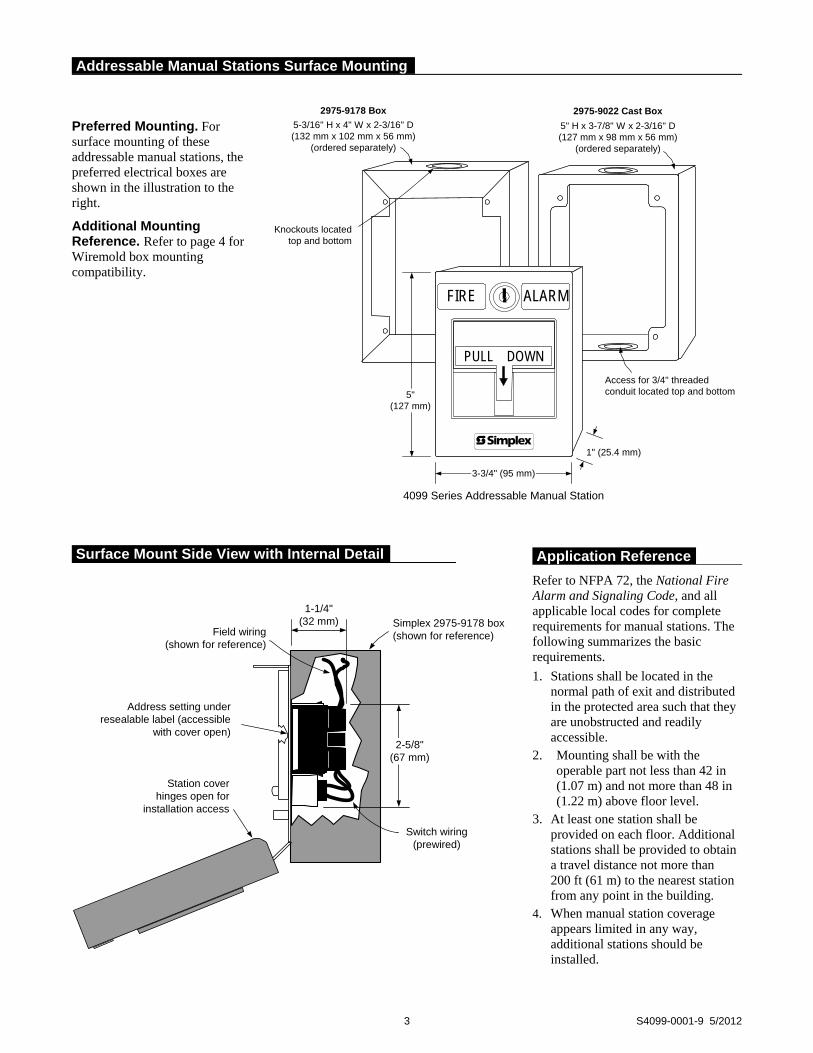
Preferred Mounting. For surface mounting of these addressable manual stations, the preferred electrical boxes are shown in the illustration to the right.
Additional Mounting Reference. Refer to page 4 for Wiremold box mounting compatibility.
3 S4099-0001-9 5/2012
Application Reference
Refer to NFPA 72, the National Fire Alarm and Signaling Code, and all applicable local codes for complete requirements for manual stations. The following summarizes the basic requirements.
1. Stations shall be located in the normal path of exit and distributed in the protected area such that they are unobstructed and readily accessible.
2. Mounting shall be with the operable part not less than 42 in (1.07 m) and not more than 48 in (1.22 m) above floor level.
3. At least one station shall be provided on each floor. Additional stations shall be provided to obtain a travel distance not more than 200 ft (61 m) to the nearest station from any point in the building.
4. When manual station coverage appears limited in any way, additional stations should be installed.
2975-9178 Box
5-3/16" H x 4" W x 2-3/16" D(132 mm x 102 mm x 56 mm)
(ordered separately)
Knockouts locatedtop and bottom
2975-9022 Cast Box
5" H x 3-7/8" W x 2-3/16" D(127 mm x 98 mm x 56 mm)
(ordered separately)
Access for 3/4" threadedconduit located top and bottom5"
(127 mm)
FIRE
ALARMFIRE
PULL DOWN
4099 Series Addressable Manual Station
1" (25.4 mm)
3-3/4" (95 mm)
Station coverhinges open for
installation access
Simplex 2975-9178 box(shown for reference)
Address setting underresealable label (accessible
with cover open)
Switch wiring(prewired)
Field wiring(shown for reference)
1-1/4"(32 mm)
2-5/8"(67 mm)
Addressable Manual Stations Surface Mounting
Surface Mount Side View with Internal Detail
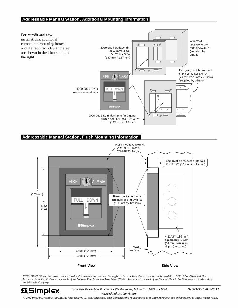
For retrofit and new installations, additional compatible mounting boxes and the required adapter plates are shown in the illustration to the right.
TYCO, SIMPLEX, and the product names listed in this material are marks and/or registered marks. Unauthorized use is strictly prohibited. NFPA 72 and National Fire Alarm and Signaling Code are trademarks of the National Fire Protection Association (NFPA). Lexan is a trademark of the General Electric Co. Wiremold is a trademark of the Wiremold Company.
8"(203 mm)
6"(152mm)
4-3/4" (121 mm)
6-3/4" (171 mm)
Front View
Flush mount adapter kit2099-9819, Black2099-9820, Beige
Wallsurface
4-11/16" (119 mm)square box, 2-1/8"(54 mm) minimumdepth (by others)
Side View
Box must be recessed into wall1" to 1-1/8" (25.4 mm to 29 mm)
Hole cutout must be aminimum of 6" H by 5" W
(152 mm by 127 mm)
2099-9814 Surface trimfor Wiremold box
5-1/8" H x 5" W(130 mm x 127 mm)
4099-9001 IDNetaddressable station
Two gang switch box, each3" H x 2" W x 2-3/4" D(76 mm x 51 mm x 70 mm)(supplied by others)
2099-9813 Semi-flush trim for 2 gangswitch box, 6" H x 4-1/2" W
(152 mm x 114 mm)
Wiremoldreceptacle boxmodel V5744-2(supplied byothers)
Tyco Fire Protection Products • Westminster, MA • 01441-0001 • USA S4099-0001-9 5/2012
www.simplexgrinnell.com © 2012 Tyco Fire Protection Products. All rights reserved. All specifications and other information shown were current as of document revision date and are subject to change without notice.
Addressable Manual Station, Additional Mounting Information
Addressable Manual Station, Flush Mounting Information

SimplexGrinnell NW Hospital OR Renovation PHASE 2_ 975156020 sub.doc
SECTION
4
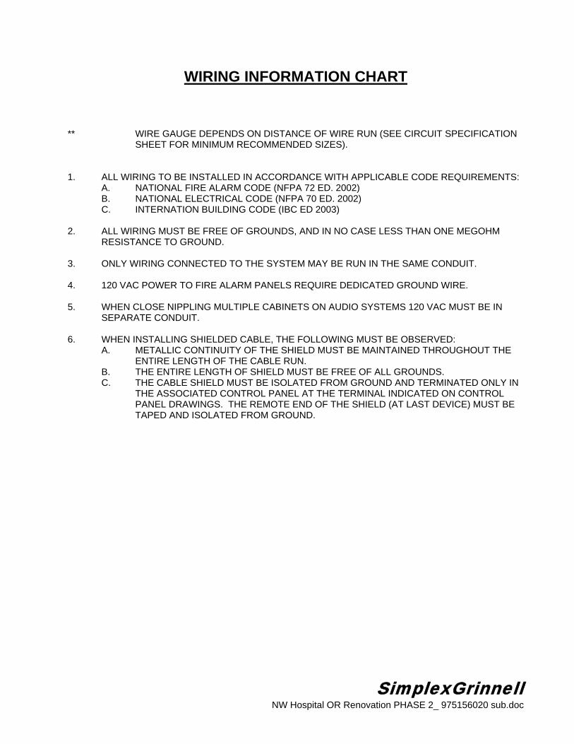
SimplexGrinnell NW Hospital OR Renovation PHASE 2_ 975156020 sub.doc
WIRING INFORMATION CHART ** WIRE GAUGE DEPENDS ON DISTANCE OF WIRE RUN (SEE CIRCUIT SPECIFICATION
SHEET FOR MINIMUM RECOMMENDED SIZES). 1. ALL WIRING TO BE INSTALLED IN ACCORDANCE WITH APPLICABLE CODE REQUIREMENTS:
A. NATIONAL FIRE ALARM CODE (NFPA 72 ED. 2002) B. NATIONAL ELECTRICAL CODE (NFPA 70 ED. 2002) C. INTERNATION BUILDING CODE (IBC ED 2003)
2. ALL WIRING MUST BE FREE OF GROUNDS, AND IN NO CASE LESS THAN ONE MEGOHM RESISTANCE TO GROUND. 3. ONLY WIRING CONNECTED TO THE SYSTEM MAY BE RUN IN THE SAME CONDUIT. 4. 120 VAC POWER TO FIRE ALARM PANELS REQUIRE DEDICATED GROUND WIRE. 5. WHEN CLOSE NIPPLING MULTIPLE CABINETS ON AUDIO SYSTEMS 120 VAC MUST BE IN SEPARATE CONDUIT. 6. WHEN INSTALLING SHIELDED CABLE, THE FOLLOWING MUST BE OBSERVED: A. METALLIC CONTINUITY OF THE SHIELD MUST BE MAINTAINED THROUGHOUT THE ENTIRE LENGTH OF THE CABLE RUN. B. THE ENTIRE LENGTH OF SHIELD MUST BE FREE OF ALL GROUNDS. C. THE CABLE SHIELD MUST BE ISOLATED FROM GROUND AND TERMINATED ONLY IN THE ASSOCIATED CONTROL PANEL AT THE TERMINAL INDICATED ON CONTROL PANEL DRAWINGS. THE REMOTE END OF THE SHIELD (AT LAST DEVICE) MUST BE TAPED AND ISOLATED FROM GROUND.

SimplexGrinnell NW Hospital OR Renovation PHASE 2_ 975156020 sub.doc
WIRE INFORMATION DISTANCE CHARTS
SPEAKERS ONLY25VRMS Power Maximum Distance In Feet (Twisted Pair Wire)
Applied Actual 18 AWG 16 AWG 14 AWG 12 AWG
50W 25W 362 576 917 1458
40W 20W 453 720 1146 1823
30W 15W 604 959 1528 2431
20W 10W 906 1439 2292 364610W 5W 1811 2878 4584 7292
70VRMS Power Maximum Distance In Feet (Twisted Pair Wire)
Applied Actual 18 AWG 16 AWG 14 AWG 12 AWG
100W 50W 1420 2256 3594 5717
80W 40W 1775 2821 4493 7146
70W 35W 2029 3223 5134 8167
60W 30W 2367 3761 5990 9528
50W 25W 2840 4513 7188 11434
40W 20W 3550 5641 8985 14293
30W 15W 4734 7521 11980 19057
20W 10W 7100 11282 17971 2858510W 5W 14201 22564 35941 57171
FLASHING LIGHTS, HORNS, BELLS AND CHIMES, ETC.Maximum Distance In Feet (2 Conductor Cable)
I Circuit Total Wire 18 AWG 16 AWG 14 AWG 12 AWG(amps) Resistance
(ohms)
0.250 14 980 1557 2480 3946
0.500 7 490 779 1240 1973
0.750 4.7 327 519 827 1315
1.000 3.5 245 389 620 986
1.250 2.8 196 311 496 789
1.500 2.3 163 260 413 658
1.750 2.0 140 222 354 5642.000 1.7 123 195 310 493
Wire resistance based on NEC Table 8 (uncoated solid copper wire) at 50 degrees Celsius

SimplexGrinnell NW Hospital OR Renovation PHASE 2_ 975156020 sub.doc
Setting the Addressable Devices Each Addressable Device has a unique address. The address of the Addressable Device is set via an eight position dip switch (Figure 1), DIP switch position 1 is the least significant bit (LSB) and position 8 is the most significant bit (MSB). Set the Addressable Device address using Figure 2 as reference. Use a small screwdriver or pen to set the switches. The device address for the Addressable Device should be written on the label, this information provides an aid in troubleshooting the system. The IDNet channel (4010 or 4100U FACP) supports address codes 1 through 250. The MAPNET II channel (4100, or 4120, or 4020 FACP) supports address codes 1 through 127. Note: DIP switch in “1” position is “ON” while DIP switch in “0” position is “OFF”.
Figure 1. Address Chart

SimplexGrinnell NW Hospital OR Renovation PHASE 2_ 975156020 sub.doc
DRAWING DISCLAIMER All drawings and wiring diagrams provided by SimplexGrinnell in connection with this project are: 1. Protected under the United States Copyright Laws. 2. Prepared in accordance with what SimplexGrinnell judges to be good system design
practice; HOWEVER, APPROVAL OF THE SYSTEM DESIGN BY THE AUTHORITY HAVING JURISDICTION IS NOT GUARANTEED.
3. Intended solely for the use of the installing contractor as a guide for the fabrication and
installation of the system. 4. Not intended to be submitted for any purpose to the authority having jurisdiction, or any
other party, except with the prior approval of SimplexGrinnell.
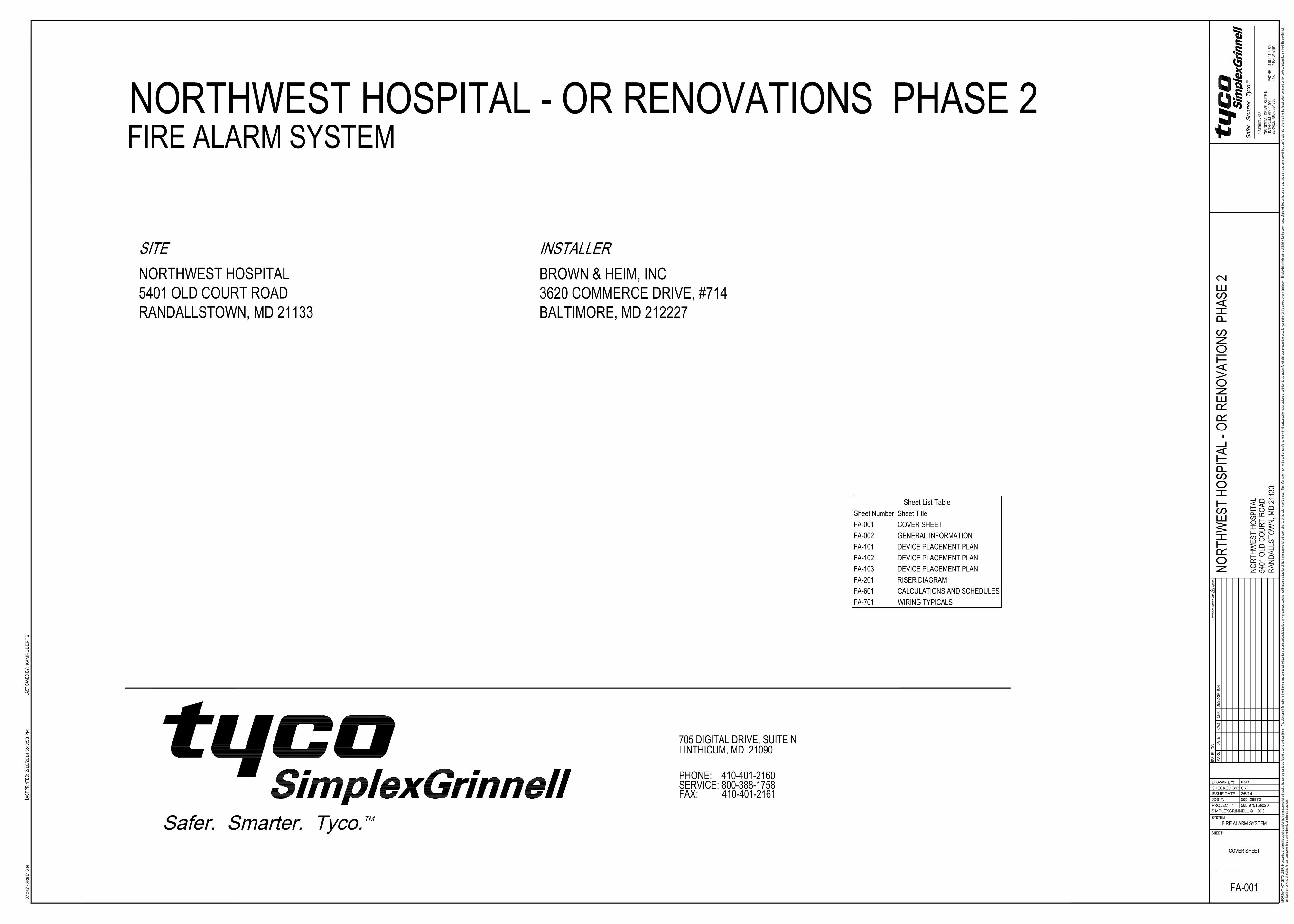
2/1
0/2
01
4 5
:4
3:5
3 P
MK
AM
RO
BE
RT
S
565:975156020
CRP
KSR
2/5/14
565428970
DRAWN BY:
CHECKED BY:
JOB #:
PROJECT #:
SIMPLEXGRINNELL ©
ISSUE DATE:

2/1
0/2
01
4 5
:4
3:5
8 P
MK
AM
RO
BE
RT
S
565:975156020
CRP
KSR
2/5/14
565428970
DRAWN BY:
CHECKED BY:
JOB #:
PROJECT #:
SIMPLEXGRINNELL ©
ISSUE DATE:
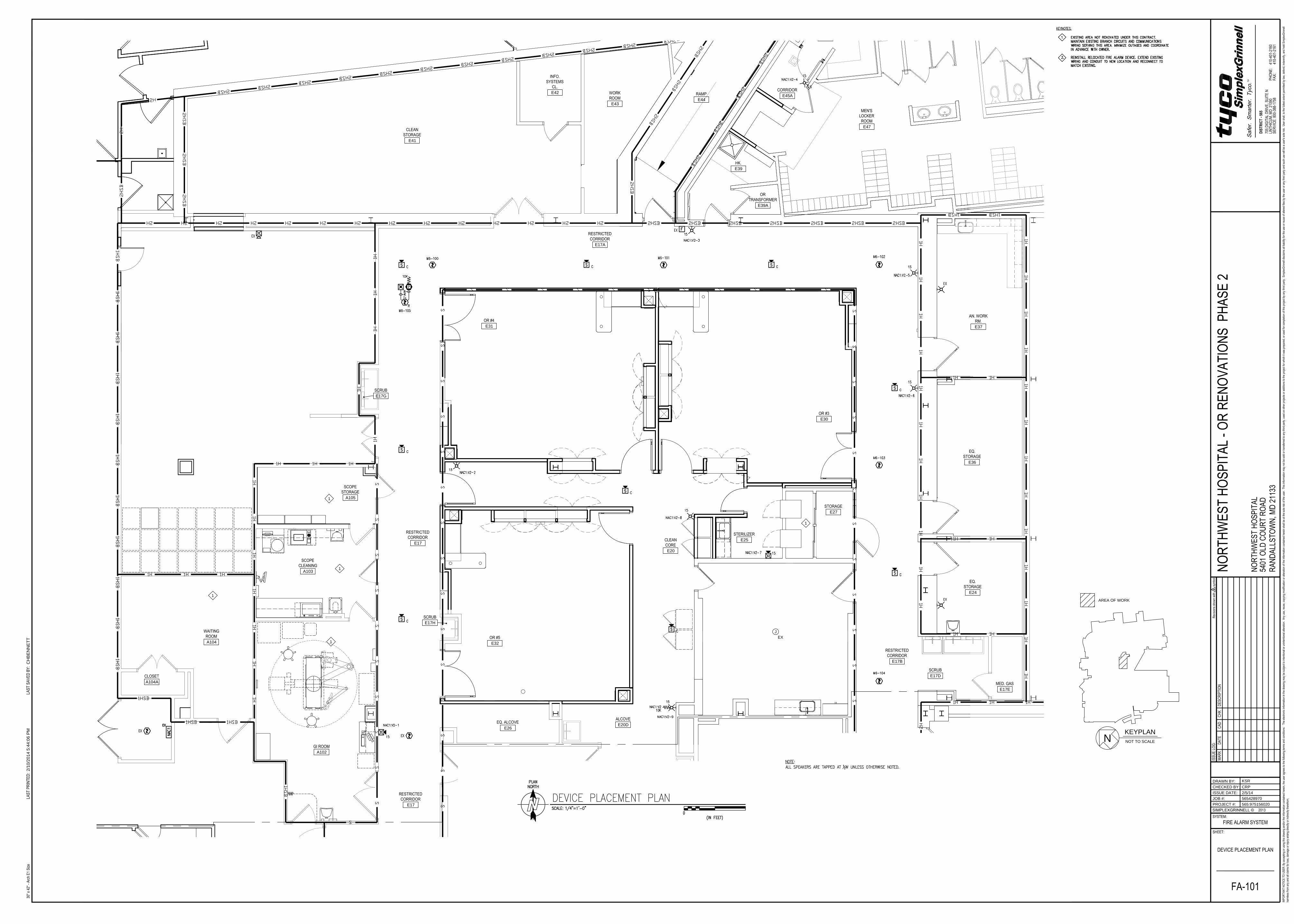
E30
E41
E42
E43
E44
E45A
E47
E39A
E39
E37
E36
E27
E25
E20
E17B
E17D
E17E
E24
E22
E21
E20D
E26
A102
E17H
E17
A103
E31
E17A
E32
A105
E17G
E17
A104
A104A
E45
J
EX
15
1
1
1
1
1
2/1
0/2
01
4 5
:4
4:0
6 P
MC
HB
EN
NE
TT
565:975156020
CRP
KSR
2/5/14
565428970
DRAWN BY:
CHECKED BY:
JOB #:
PROJECT #:
SIMPLEXGRINNELL ©
ISSUE DATE:
N
KEYPLAN
NOT TO SCALE
AREA OF WORK
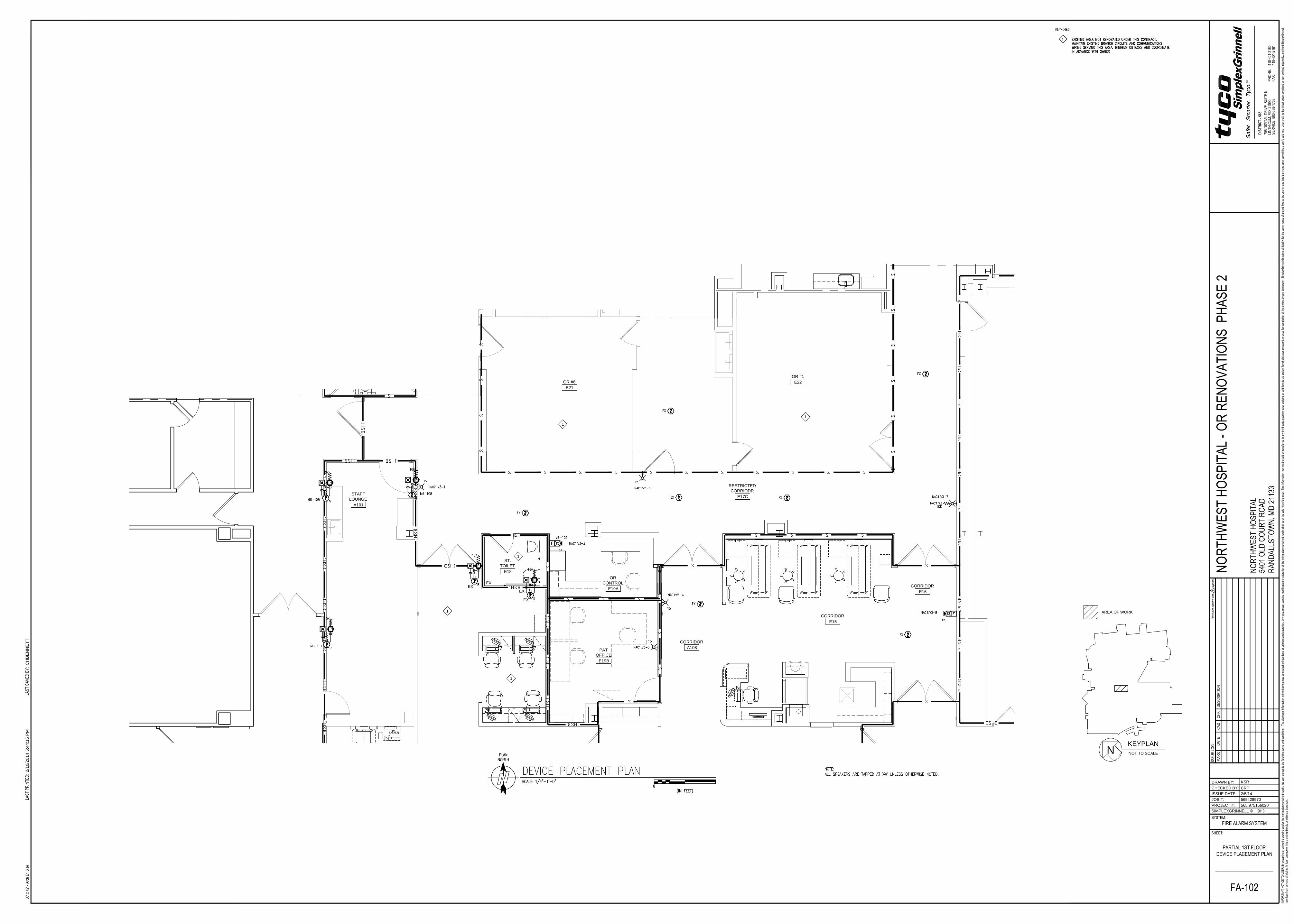
OR #1
E22OR #6
E21
ALCOVE
E20D
EQ.
ALCOVE
E26
GI ROOM
A102
STAFF
LOUNGE
A101
ST.
TOILET
E18
CORRIDOR
A108
CORRIDOR
E16
RESTRICTED
CORRIDOR
E17
OR
CONTROL
E19A
PAT
OFFICE
E19B
CORRIDOR
E15
RESTRICTED
CORRIODR
E17C
1
1
1
1
D
D
EX
EX
EX
EX
1
2/1
0/2
01
4 5
:4
4:1
5 P
MC
HB
EN
NE
TT
565:975156020
CRP
KSR
2/5/14
565428970
DRAWN BY:
CHECKED BY:
JOB #:
PROJECT #:
SIMPLEXGRINNELL ©
ISSUE DATE:
N
KEYPLAN
NOT TO SCALE
AREA OF WORK
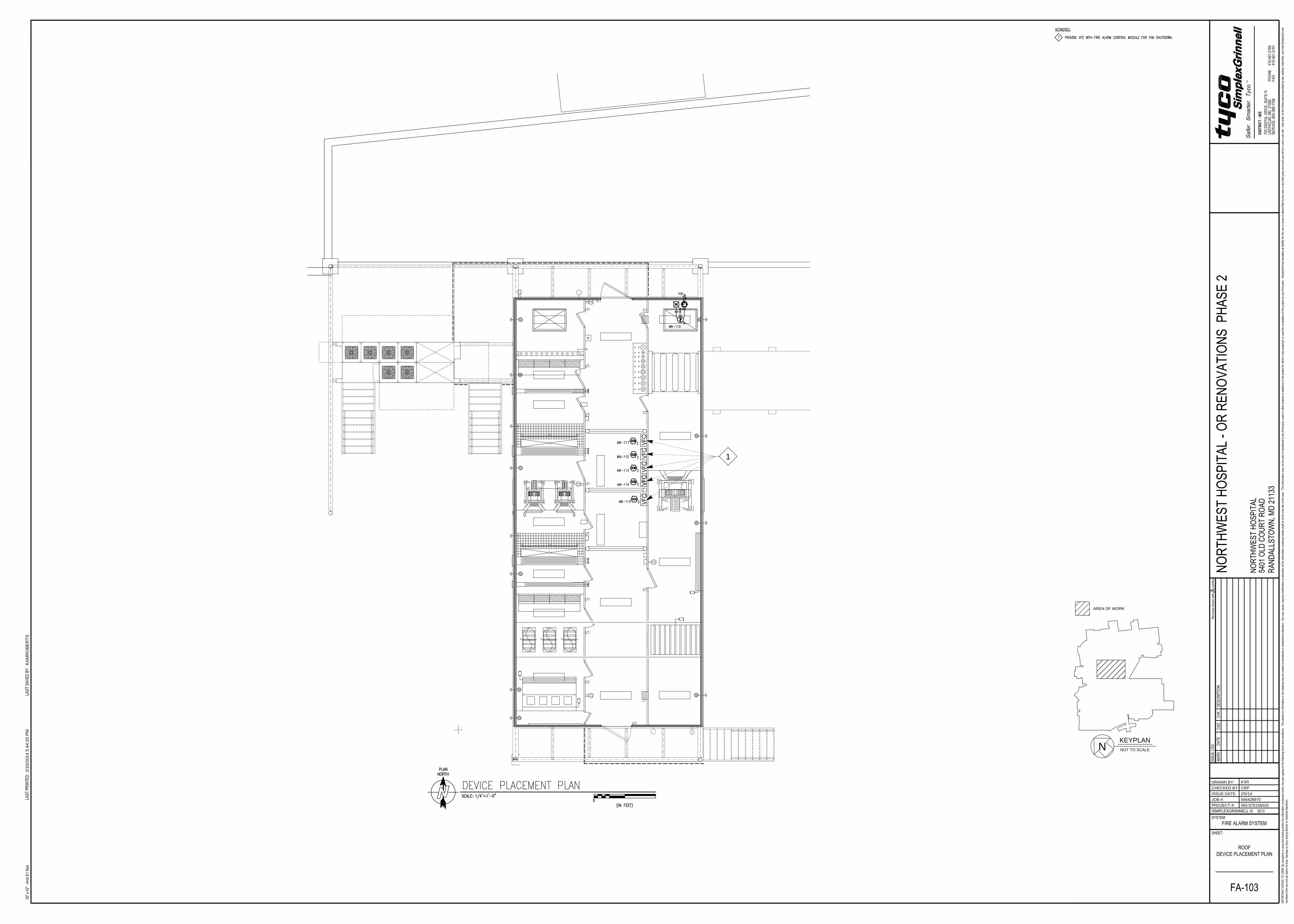
1
2/1
0/2
01
4 5
:4
4:2
0 P
MK
AM
RO
BE
RT
S
565:975156020
CRP
KSR
2/5/14
565428970
DRAWN BY:
CHECKED BY:
JOB #:
PROJECT #:
SIMPLEXGRINNELL ©
ISSUE DATE:
N
KEYPLAN
NOT TO SCALE
AREA OF WORK
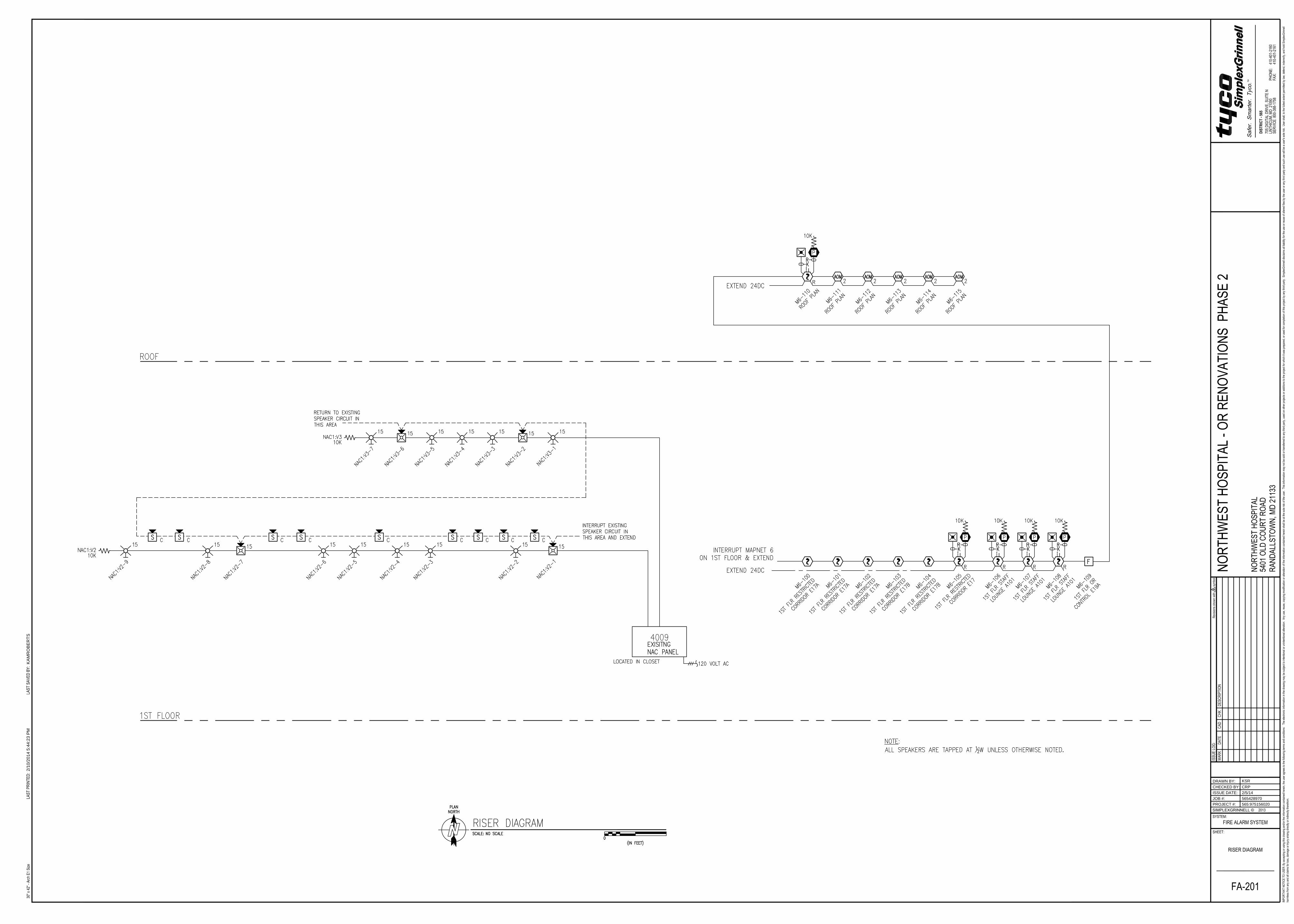
2/1
0/2
01
4 5
:4
4:2
3 P
MK
AM
RO
BE
RT
S
565:975156020
CRP
KSR
2/5/14
565428970
DRAWN BY:
CHECKED BY:
JOB #:
PROJECT #:
SIMPLEXGRINNELL ©
ISSUE DATE:
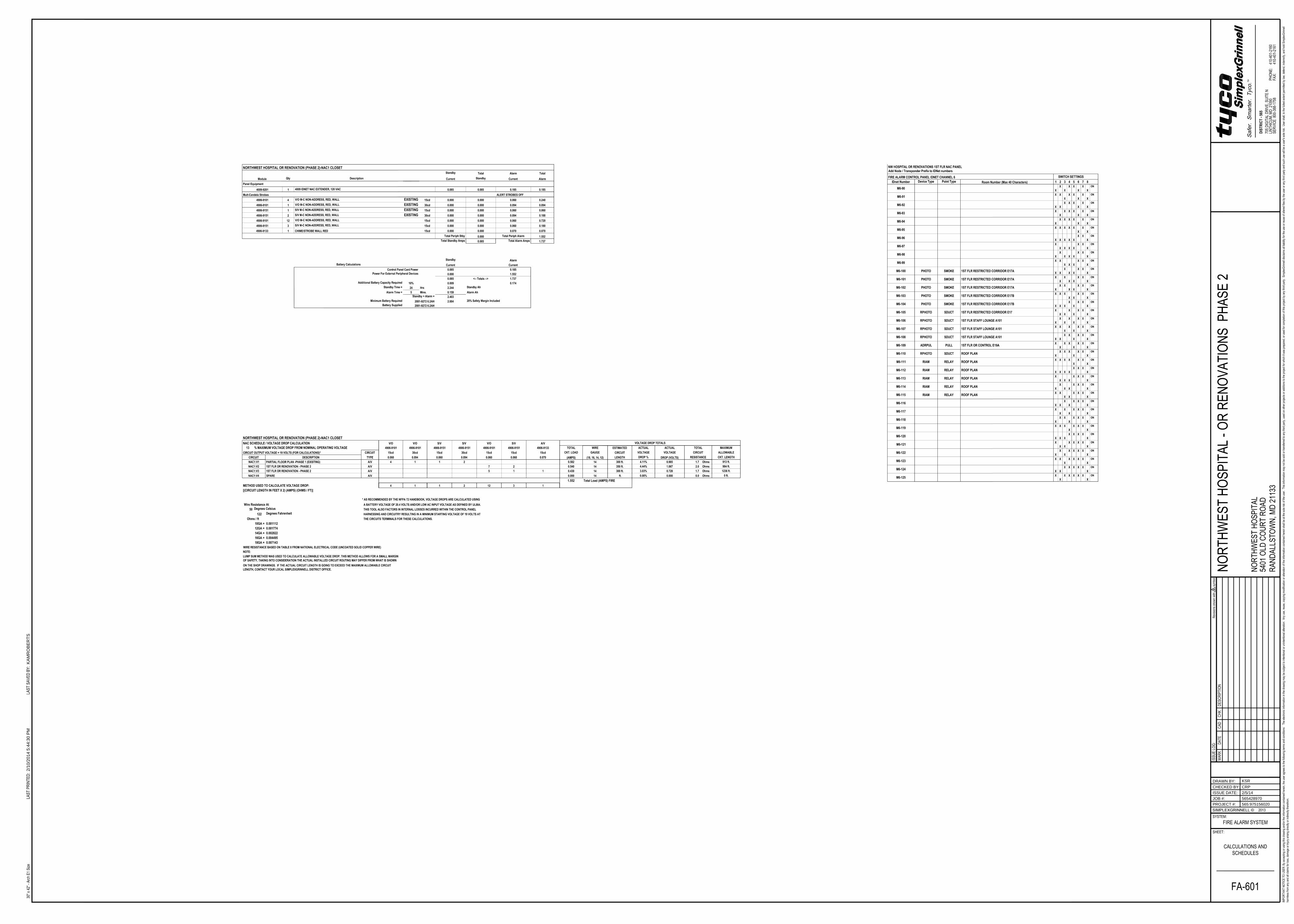
2/1
0/2
01
4 5
:4
4:3
0 P
MK
AM
RO
BE
RT
S
565:975156020
CRP
KSR
2/5/14
565428970
DRAWN BY:
CHECKED BY:
JOB #:
PROJECT #:
SIMPLEXGRINNELL ©
ISSUE DATE:
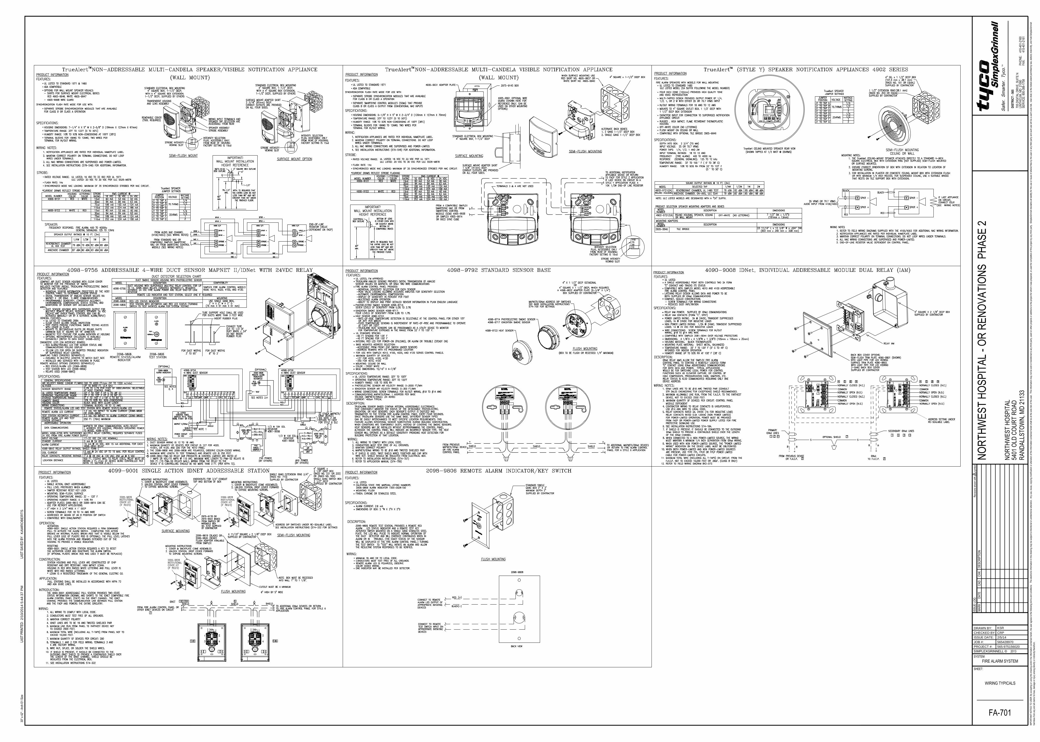
110
75
30
15
110
75
30
15
110
30
15
75
2/1
0/2
01
4 5
:4
4:3
7 P
MK
AM
RO
BE
RT
S
565:975156020
CRP
KSR
2/5/14
565428970
DRAWN BY:
CHECKED BY:
JOB #:
PROJECT #:
SIMPLEXGRINNELL ©
ISSUE DATE: