Project Module ITE/CW/SYT - AT...
19
Project Module ITE/CW/SYT Module Unit Code: EC3029PA Page 1 of 19 Job No: 09 Duration: 24H Job Title: Materials and Maps Objective: Use 3ds Max material and map are to define surface attributes such as color, glossiness, and transparency. Students should be able to create and • Slate Material Editor • Material • Material Modifier • UVW Maps Modifier • Blend Materials Introduction: Materials are like paint. With materials, you make apples red and oranges orange. You put the shine in chrome and the polish on glass. By applying maps, you can add images, patterns, and even surface texture to objects. Materials are what make your scenes look real. Mapping is a method of projecting pictorial information (materials) onto surfaces. It is a lot like wrapping a present with wrapping paper, except the pattern is projected mathematically, with modifiers, rather than being taped to the surface. There are two terms in computer graphics that are often used interchangeably, but are actually very different: materials and maps. Materials – materials contain all the surface attributes applied to the objects in the scene. Maps – maps are patterns within a material; colour, texture or transparency.
Transcript of Project Module ITE/CW/SYT - AT...

Project Module ITE/CW/SYT
Module Unit Code: EC3029PA Page 1 of 19
Job No: 09 Duration: 24H Job Title: Materials and Maps Objective: Use 3ds Max material and map are to define surface attributes such as color, glossiness, and transparency. Students should be able to create and
• Slate Material Editor • Material • Material Modifier • UVW Maps Modifier • Blend Materials
Introduction:
Materials are like paint. With materials, you make apples red and oranges orange. You put the shine in chrome and the polish on glass. By applying maps, you can add images, patterns, and even surface texture to objects. Materials are what make your scenes look real.
Mapping is a method of projecting pictorial information (materials) onto surfaces. It is a lot like wrapping a present with wrapping paper, except the pattern is projected mathematically, with modifiers, rather than being taped to the surface. There are two terms in computer graphics that are often used interchangeably, but are actually very different: materials and maps.
Materials – materials contain all the surface attributes applied to the objects in the scene.
Maps – maps are patterns within a material; colour, texture or transparency.

Project Module ITE/CW/SYT
Module Unit Code: EC3029PA Page 2 of 19
Slate Material Editor:
The Slate Material Editor is a material editor interface that uses nodes and wiring to graphically display the structure of materials while you design and edit them. It is an alternative to the Compact Material Editor.
In general, the Slate interface is more versatile when you are designing materials, while the Compact interface is more convenient when you just need to apply materials that have already been designed.
Interface
The Slate interface is a graphical interface with several elements. Most prominent are the Material/Map Browser, where you can browse for materials, maps, and base material and map types; the active View, where you can combine materials and maps; and the Parameter Editor, where you can change material and map settings.
1. Menu bar 2. Toolbar 3. Material/Map Browser 4. Status 5. Active View 6. View navigation 7. Parameter Editor 8. Navigator

Project Module ITE/CW/SYT
Module Unit Code: EC3029PA Page 3 of 19
Slate Material Editor Toolbar:
Select Tool Activates the Select tool. (Select is always active unless you have chosen one of the modal navigation tools such as Zoom or Pan.) Keyboard shortcut: S Menu choice: Select Select Tool
Pick Material from Object After you click this button, 3ds Max displays an eyedropper cursor. Click an object in a viewport to display its material in the current View. Menu choice: Material Pick from Object
Put Material to Scene This is available only when you have a copy of a material that has the same name as a material applied to objects, and you have edited the copy to change the properties of the material. Choosing Put Material To Scene updates the objects that have the older material applied to them.
Assign Material to Selection Assigns the current material to all objects in the current selection. See To apply a material to objects in a scene. Keyboard shortcut: A Menu choice: Material Assign Material to Selection
Delete Selected In the active View, deletes the selected nodes or wires. Keyboard shortcut: Delete Menu choice: Edit Delete Selected
Move Children When on, moving a parent node moves the child nodes along with the parent. When off, moving a parent node doesn’t change the children’s position. Default=off. Keyboard shortcut: Alt+C Temporary shortcut: Ctrl+Alt+drag moves a node with its children, but doesn’t turn on the Move Children toggle. Menu choice: Options Move Children

Project Module ITE/CW/SYT
Module Unit Code: EC3029PA Page 4 of 19
Hide Unused Nodeslots
For a selected node, toggles display of the unused slots when the node is open. When on, unused nodes slots are hidden. Default=off. Keyboard shortcut: H Menu choice: View Hide Unused Nodeslots
Show Map in Viewport The control for showing maps in viewports is a flyout with four possible states:
• Show Shaded Map in Viewport [off]: Uses the 3ds Max software display and disables viewport display of all maps for the active material.
• Show Shaded Map in Viewport [on]: Uses the 3ds Max software display and enables viewport display of all maps for the active material.
• Show Realistic Map in Viewport [off]: Uses the hardware display and disables viewport display of all maps for the active material.
• Show Realistic Map in Viewport [on]: Uses the hardware display and enables viewport display of all maps for the active material.
Material:
A material is data that you assign to the surface or faces of an object so that it appears a certain way when rendered. Materials can affect object color, glossiness, opacity, and so on.
Spheres with variations of the standard material type (no maps used): Green sphere: High Glossiness Red sphere: Constant shading Blue sphere: 60% opacity Yellow sphere: Wireframe mode, slight self-illumination
A standard material consists of ambient, diffuse, and specular components. You can assign maps to the various components of a standard material.

Project Module ITE/CW/SYT
Module Unit Code: EC3029PA Page 5 of 19
The standard material is the default material in the six sample slots of the Material Editor. However, you can change the type of material you're working on by clicking the button labeled Type below the sample slots. This displays the Material/Map Browser, and lets you select from a list of alternative material types.
You can also change the type of material you're working on by clicking the Get Material button below the sample slots. This displays the Material/Map Browser, and lets you select from a list of alternative material types.
Material Modifier:
The Material modifier allows you to animate, or simply change, the assignment of material IDs on an object. If the material ID is animated, the change to a new material ID is abrupt, from one frame to the next.
Object mapped using a Multi/Sub-Object material: Material ID 1 for the housing of the monitor Material ID 2 for the image on the screen
Project Module ITE/CW/SYT
Module Unit Code: EC3029PA Page 6 of 19
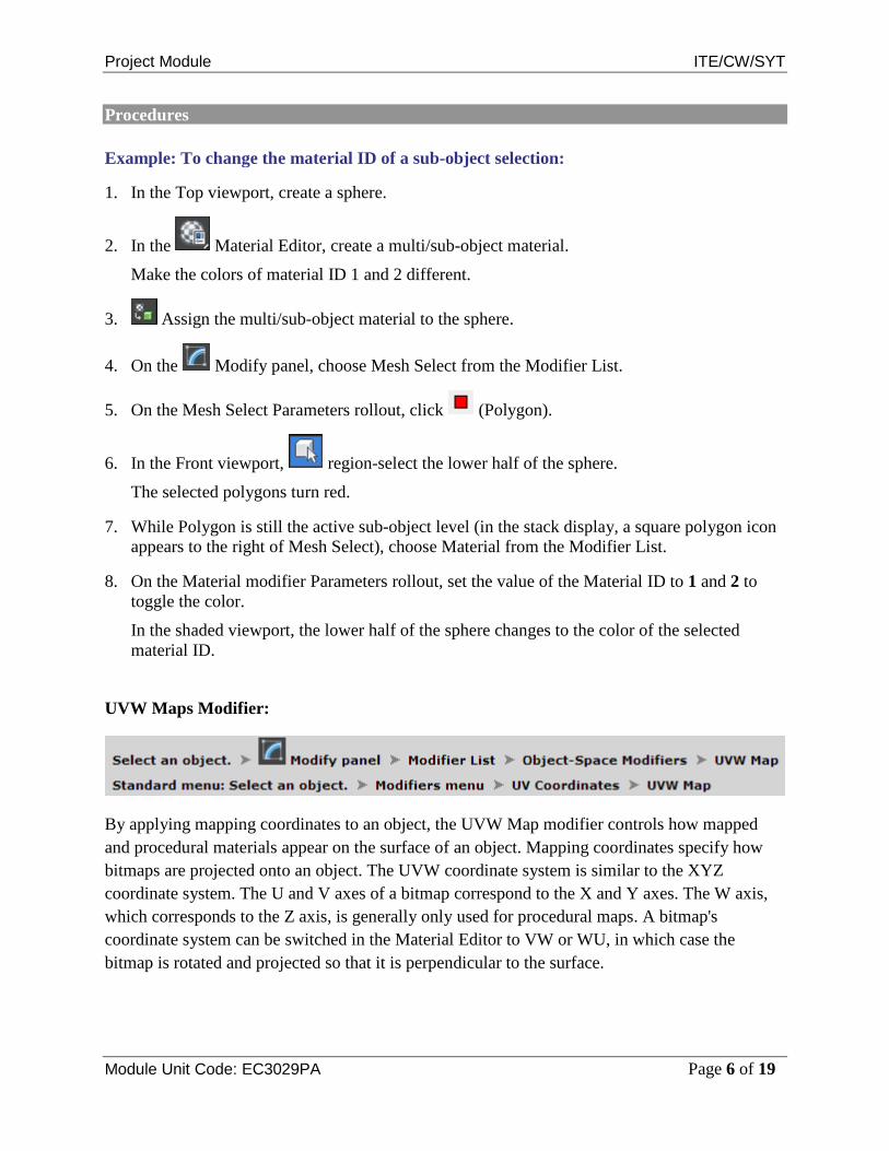
Procedures
Example: To change the material ID of a sub-object selection:
1. In the Top viewport, create a sphere.
2. In the Material Editor, create a multi/sub-object material.
Make the colors of material ID 1 and 2 different.
3. Assign the multi/sub-object material to the sphere.
4. On the Modify panel, choose Mesh Select from the Modifier List.
5. On the Mesh Select Parameters rollout, click (Polygon).
6. In the Front viewport, region-select the lower half of the sphere.
The selected polygons turn red.
7. While Polygon is still the active sub-object level (in the stack display, a square polygon icon appears to the right of Mesh Select), choose Material from the Modifier List.
8. On the Material modifier Parameters rollout, set the value of the Material ID to 1 and 2 to toggle the color.
In the shaded viewport, the lower half of the sphere changes to the color of the selected material ID.
UVW Maps Modifier:
By applying mapping coordinates to an object, the UVW Map modifier controls how mapped and procedural materials appear on the surface of an object. Mapping coordinates specify how bitmaps are projected onto an object. The UVW coordinate system is similar to the XYZ coordinate system. The U and V axes of a bitmap correspond to the X and Y axes. The W axis, which corresponds to the Z axis, is generally only used for procedural maps. A bitmap's coordinate system can be switched in the Material Editor to VW or WU, in which case the bitmap is rotated and projected so that it is perpendicular to the surface.

Project Module ITE/CW/SYT
Module Unit Code: EC3029PA Page 7 of 19
Mapping a sphere and a box.
By default, primitive objects such as spheres and boxes have mapping coordinates, as do loft objects and NURBS surfaces. Scanned, imported, or hand-constructed polygonal or patch models do not have mapping coordinates until a UVW Map modifier is applied.
If you apply a UVW Map modifier to an object with built-in mapping coordinates, the applied coordinates take precedence if map channel 1 in the UVW Map modifier is used. The Generate Mapping Coordinates option, available during the creation of primitives, uses map channel 1 by default.
You use the UVW Map modifier to:
• Apply one of the seven types of mapping coordinates to an object on a specified map channel. A diffuse map on map channel 1 and a bump map on map channel 2 can have different mapping coordinates and can be controlled separately by using two UVW Map modifiers in the modifier stack
• Apply one of the seven types of mapping coordinates to an object.
• Transform the mapping gizmo to adjust map placement. Objects with built-in mapping coordinates lack a gizmo.
• Apply mapping coordinates to an object with no mapping coordinates, an imported mesh, for example.
• Apply mapping at the sub-object level.

Project Module ITE/CW/SYT
Module Unit Code: EC3029PA Page 8 of 19
Transforming UVW Map Gizmos
Changing a map's location by moving the gizmo.
The UVW Map gizmo projects mapping coordinates onto an object. You can position, rotate, or scale a gizmo to adjust map coordinates on an object; you can also animate the gizmo. Gizmo transformations remain in effect if you select a new map type. For example, if you scale a spherical mapping gizmo and then switch to planar mapping, then the planar mapping gizmo is also scaled.

Project Module ITE/CW/SYT
Module Unit Code: EC3029PA Page 9 of 19
Procedures
To apply the UVW Map modifier:
1. Assign a mapped material to an object.
2. On the Modify panel Modifier List, choose UVW Map.
3. Adjust the mapping parameters. By default, the UVW Map modifier uses planar mapping on map channel 1. You can change the type of mapping and the map channel to suit your needs. There are seven types of mapping coordinates, ninety-nine map channels, tiling controls, and controls to size and orient the mapping gizmo in the UVW Map modifier. NoteIf a UVW Map modifier is applied to multiple objects, the UVW Map gizmo is defined by the selection, and the mapping that results is applied to all the objects.
To use multiple UVW channels in the same object:
1. Assign Map channel 1 to an object. You can do this by either turning on Generate Mapping Coordinates in the Parameters rollout of any primitive, or by assigning a UVW Map modifier with channel 1 chosen.
Generate Mapping Coordinates uses map channel 1 by default.
2. Assign a UVW Map modifier (or a second one, if you're using the first to assign channel 1). Choose channel 2 for this modifier.
Both coordinate channels are now assigned to the geometry. The next step is to assign a mapped material that uses both channels.
3. Create a material with two maps. You can do this using a Composite map, or a Blend material with two maps, or you can have one map assigned to Diffuse and another assigned to Bump. Perhaps the easiest way to see the effect is to composite two maps, with the second map containing an alpha channel.
4. Go to the level of one of the maps and, in the Mapping list, choose Explicit Map Channel 2. The other map is already assigned channel 1 by default.
5. Assign the mapped material to the object. You can switch between viewing the maps in the viewport using the Show Map In Viewport control in the Material Editor. You can adjust the mapping of channel 2 without altering the mapping of channel 1 if you've assigned two UVW Map modifiers. Render the scene to see the effect.

Project Module ITE/CW/SYT
Module Unit Code: EC3029PA Page 10 of 19
Example: To use the XYZ to UVW option:
The XYZ to UVW option lets you make a 3D procedural texture, like Cellular, follow the animated surface of an object. If the object stretches, so does the 3D procedural texture.
1. In the Top viewport, create a box.
2. Create a material with a Cellular diffuse map.
3. In the Material Editor, on the Coordinates rollout of the Cellular map, open the Source drop-down list, and choose Explicit Map Channel.
On the Coordinates rollout, the Map Channel parameter activates, leave the value at 1.
4. Assign the material to the box.
5. On the Modify panel Modifier List, choose UVW Map.
6. On the UVW Map modifier, turn on XYZ to UVW. By default, the Map Channel value is 1.
7. Render the Front viewport.
The cellular pattern renders normally on the surface of the box.
8. Right-click over the object and choose Convert To: Convert to Editable Mesh from the Transform (lower-right) quadrant of the quad menu.
The box is converted to an editable mesh.
9. On the Modify panel Selection rollout, click (Vertex) to turn it on.
10. In the Front viewport, select the top vertices of the box, and move them up.
11. Render the Front viewport again.
The cellular pattern stretches with the box. This effect is enabled by the XYZ to UVW option. To see the difference, we will change the Source option in the Coordinates rollout in the Material Editor.
12. In the Material Editor, locate the diffuse Cellular material.
13. On the Coordinates rollout of the Cellular diffuse map, open the Source drop-down list and choose Object XYZ.
14. Render the Front viewport. The cellular pattern is no longer stretched.

Project Module ITE/CW/SYT
Module Unit Code: EC3029PA Page 11 of 19
To transform the UVW Map gizmo:
1. On the Modify panel, choose the UVW Mapping modifier in the stack display.
2. In the stack display, choose the Gizmo sub-object level.
The gizmo changes to a yellow color, with one green edge.
The green edge indicates the right edge of the texture.
3. Move, scale, or rotate the gizmo in the viewports, or use the Length and Width controls in the UVW Map modifier.
Transforming the map gizmo shifts the bitmap, allowing you to orient and move the map on the object's surface.
To use manipulators to control the width and length:
1. On the Modify panel, choose the UVW Map modifier in the stack display.
You can also be at the Gizmo level of the modifier.
2. On the main toolbar, click to turn on (Select And Manipulate).
Green edges appear along the sides of the UVW Map modifier's gizmo. An edge turns red when you move the mouse over it.
3. Drag an edge of the gizmo to adjust the width or length. A tooltip shows the new width or length value.
To use manipulators to control vertical scale:
1. On the Modify panel, choose the UVW Map modifier in the stack display.
You can also be at the Gizmo level of the modifier.
2. On the main toolbar, click to turn on (Select And Manipulate).
For 3D mapping types, a green cube appears at the top of the UVW Map modifier's gizmo. The cube turns red when you move the mouse over it.
3. Drag the cube to adjust the height of the gizmo. A tooltip shows the new tiling value in the vertical dimension.

Project Module ITE/CW/SYT
Module Unit Code: EC3029PA Page 12 of 19
Mapping group
Determines the type of mapping coordinates used. Different kinds of mapping are distinguished by how the map is geometrically projected onto the object and how the projection interacts with the object's surfaces. NoteWhen Real-World Map Size is on, only the Planar, Cylindrical, Spherical, and Box mapping types are available. Similarly, if one of the other options (Shrink Wrap, Face, or XYZ To UVW) is active, Real-World Map Size is unavailable.
Planar Projects the map from a single plane flat against the object, somewhat like projecting a slide. Planar projection is useful when only one side of an object needs to be mapped. It is also useful for obliquely mapping multiple sides, and for mapping two sides of a symmetrical object.
Planar map projection

Project Module ITE/CW/SYT
Module Unit Code: EC3029PA Page 13 of 19
Cylindrical Projects the map from a cylinder, wrapping it around an object. Seams where the edges of the bitmap meet are visible unless a seamless map is used. Cylindrical projection is useful for objects that are roughly cylindrical in shape.
Cylindrical map projection
Cap Applies planar mapping coordinates to the caps of the cylinder. Note If the ends of the object geometry are not at right angles to the sides, the Cap projection bleeds onto the sides of the object.
Spherical Surrounds the object by projecting the map from a sphere. You see a seam and mapping singularities at the top and bottom of the sphere where the bitmap edges meet at the sphere's poles. Spherical mapping is useful for objects that are roughly spherical in shape.
Spherical map projection

Project Module ITE/CW/SYT
Module Unit Code: EC3029PA Page 14 of 19
Shrink Wrap Uses spherical mapping, but truncates the corners of the map and joins them all at a single pole, creating only one singularity. Shrink-wrap mapping is useful when you want to hide the mapping singularity.
Shrink-wrap projection
Box Projects the map from the six sides of a box. Each side projects as a planar map, and the effect on the surface depends on the surface normal. Each face is mapped from the closest box surface whose normal most closely parallels its own normal.
Box projection (shown on a box and on a sphere)

Project Module ITE/CW/SYT
Module Unit Code: EC3029PA Page 15 of 19
Face Applies a copy of the map to every face of an object. Pairs of faces sharing a hidden edge are mapped with the full rectangular map. Single faces with no hidden edge are mapped with a triangular portion of the map.
Face projection
XYZ to UVW Maps 3D procedural coordinates to UVW coordinates. This "sticks" the procedural texture to the surface. If the surface stretches, so does the 3D procedural map. Use this option with procedural textures, like Cellular, on objects with animated topologies.
For more information on how to use this option, see Example: To use the XYZ to UVW option:. TipIn the Material Editor's Coordinates rollout for the map, set Source to Explicit Map Channel. Use the same map channel in the material and UVW Map modifier.
Project Module ITE/CW/SYT
Module Unit Code: EC3029PA Page 16 of 19
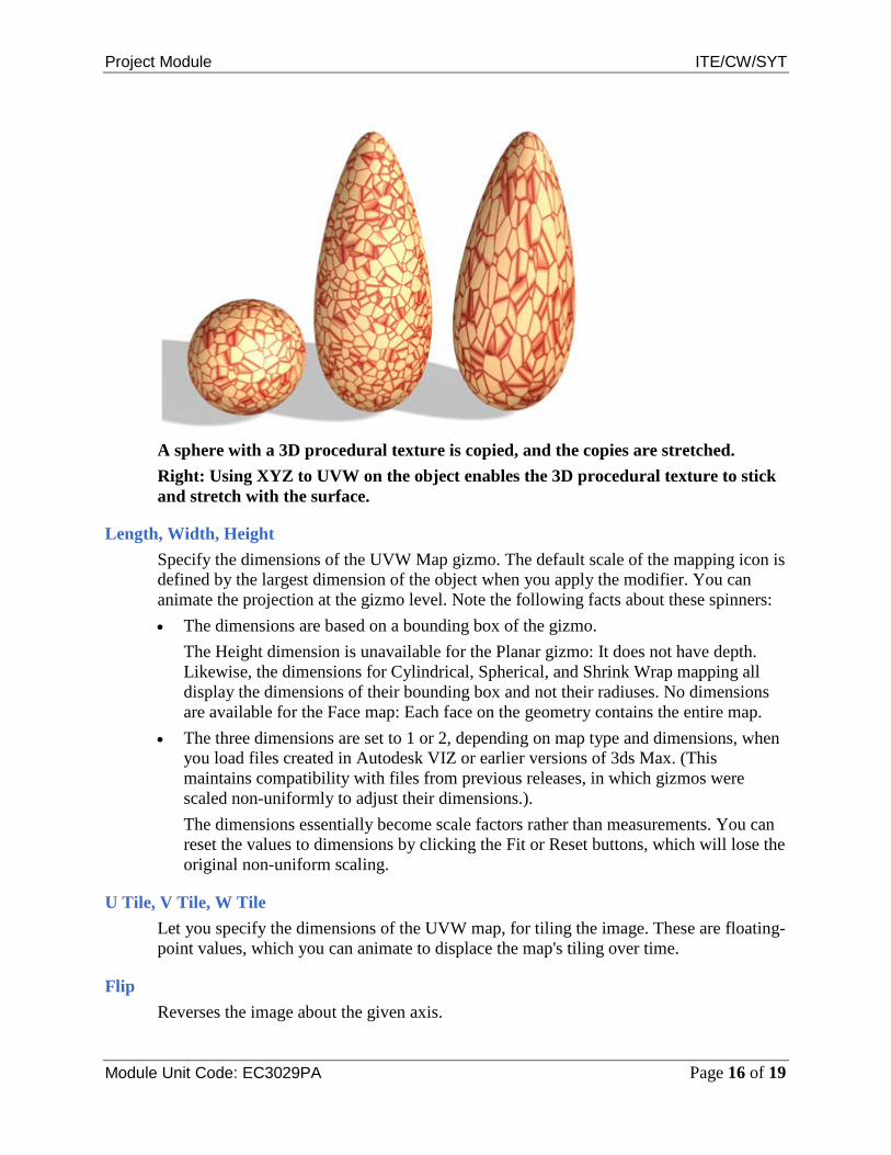
A sphere with a 3D procedural texture is copied, and the copies are stretched. Right: Using XYZ to UVW on the object enables the 3D procedural texture to stick and stretch with the surface.
Length, Width, Height Specify the dimensions of the UVW Map gizmo. The default scale of the mapping icon is defined by the largest dimension of the object when you apply the modifier. You can animate the projection at the gizmo level. Note the following facts about these spinners: • The dimensions are based on a bounding box of the gizmo.
The Height dimension is unavailable for the Planar gizmo: It does not have depth. Likewise, the dimensions for Cylindrical, Spherical, and Shrink Wrap mapping all display the dimensions of their bounding box and not their radiuses. No dimensions are available for the Face map: Each face on the geometry contains the entire map.
• The three dimensions are set to 1 or 2, depending on map type and dimensions, when you load files created in Autodesk VIZ or earlier versions of 3ds Max. (This maintains compatibility with files from previous releases, in which gizmos were scaled non-uniformly to adjust their dimensions.). The dimensions essentially become scale factors rather than measurements. You can reset the values to dimensions by clicking the Fit or Reset buttons, which will lose the original non-uniform scaling.
U Tile, V Tile, W Tile Let you specify the dimensions of the UVW map, for tiling the image. These are floating-point values, which you can animate to displace the map's tiling over time.
Flip Reverses the image about the given axis.

Project Module ITE/CW/SYT
Module Unit Code: EC3029PA Page 17 of 19
Real-World Map Size When on, uses real-world mapping for texture-mapped materials that are applied to the object. The scaling values are controlled by the Use Real-World Scale settings found on the applied material's Coordinates rollout. (Both Real-World Map Size and Use Real-World Scale should be either off or on at the same time.) Default = off for 3ds Max, on for 3ds MaxDesign. When on, the Length, Width, Height and Tiling spinners are unavailable.
Blend Materials:
The Blend material lets you mix two materials on a single side of the surface. Blend has an animatable Mix Amount parameter that lets you draw material morphing function curves to control the way that the two materials are blended over time.
Blend material combines bricks and stucco.
Procedures
To create a Blend material, do one of the following:
• In the Slate Material Editor Browser panel Materials Standard group, drag a Blend material into the active View (or double-click the Blend entry).

Project Module ITE/CW/SYT
Module Unit Code: EC3029PA Page 18 of 19
• In the Compact Material Editor, activate a sample slot, click the Type button, then in the Material/Map Browser, choose Blend and then click OK.
3ds Max opens a Replace Map dialog. This dialog asks whether you want to discard the original material in the sample slot, or retain it as a sub-material.
The controls for Blend materials are similar to the controls for Mix maps.
To specify a component material, do one of the following:
• On the Blend Basic Parameters rollout, click one of the two material buttons. The parameters for the sub-material are displayed. By default, a sub-material is a Standard material with Blinn shading.
• In the Slate Material Editor, the default sub-materials appear as nodes in the active View. You can double-click either of these nodes to see and adjust the material parameters, or you can replace the Standard material nodes with nodes of a different type.
To control the mix amount:
• In the Basic Parameters rollout, adjust the Mix Amount value. You can also control the mix amount by using a map.
Map used to reveal brick beneath stucco
To control the mix amount using a map, do one of the following:
• In the Basic Parameters rollout, click the map button next to Mask. 3ds Max opens the Browser so you can select a map type.
The intensity of pixels in this mixing map controls the mix. When the intensity is close to zero, one of the component colors or maps is visible; when it is close to full intensity, the other component is visible. Tip Using a Noise map for the mixing map can create effective results with a natural appearance.

Project Module ITE/CW/SYT
Module Unit Code: EC3029PA Page 19 of 19
The Mix Amount setting is unavailable when a map is assigned to the Mask parameter. If Use Curve is off, the mixing map is used as is. When Use Curve is on, you can use the mixing curve to shift the effect of the mask map's gradient ramp to reveal more of one material and less of the other.
• In the Slate Material Editor, add the map type you want to the active View, then wire the map node to the Blend material’s Mask component.
Interface
Material 1/Material 2 Set the two materials to be blended. Use the checkboxes to turn the materials on and off.
Interactive Chooses which of the two materials or the mask map is displayed on object surfaces in viewports by the interactive renderer. If one material has Show Map in Viewport on, this takes precedence over the Interactive setting. Only one map at a time can be displayed in viewports.
Mask Click to assign a map to use as a mask. The degree of blending between the two materials depends on the intensity of the mask map. Lighter (whiter) areas of the mask show more of Material 1, while darker (blacker) areas of the mask show more of Material 2. Use the checkbox to turn the mask map on or off.
Mix Amount Determines the proportion of the blend (percentage). 0 means only Material 1 is visible on the surface; 100 means only Material 2 is visible. Unavailable if you have assigned a mask map and the mask's checkbox is on. You can animate this parameter. Create Material Preview is useful for testing the effect.