Etanorm SYT Installation/Operating Manual - sal...
66
Thermal Oil / Hot Water Pump Etanorm SYT Installation/Operating Manual Order number:
Transcript of Etanorm SYT Installation/Operating Manual - sal...

Thermal Oil / Hot Water Pump
Etanorm SYT
Installation/OperatingManual
Order number:

Legal information/Copyright Installation/Operating Manual Etanorm SYTOriginal operating manual KSB Aktiengesellschaft Pegnitz All rights reserved. Contents provided herein must neither be distributed, copied, reproduced, editedor processed for any other purpose, nor otherwise transmitted, published or made available to a thirdparty without KSB´s express written consent. Subject to technical modification without prior notice. © KSB Aktiengesellschaft Frankenthal 21.03.2011

Contents
Glossary ................................................................................................ 5
1 General ................................................................................................ 6
1.1 Principles .......................................................................................................... 6
1.2 Installation of partly completed machinery .................................................. 6
1.3 Target group ................................................................................................... 6
1.4 Other applicable documents .......................................................................... 6
1.5 Symbols ............................................................................................................ 6
2 Safety ................................................................................................... 8
2.1 Key to safety symbols/markings ..................................................................... 8
2.2 General ............................................................................................................ 8
2.3 Intended use .................................................................................................... 8
2.4 Personnel qualification and training ............................................................. 9
2.5 Consequences and risks caused by non-compliance with these operatinginstructions ...................................................................................................... 9
2.6 Safety awareness ............................................................................................. 9
2.7 Safety information for the operator/user .................................................... 10
2.8 Safety information for maintenance, inspection and installation work ... 10
2.9 Unauthorised modes of operation ............................................................... 10
2.10 Explosion protection ..................................................................................... 10
3 Transport/Temporary Storage/Disposal ........................................... 13
3.1 Checking the condition upon delivery ......................................................... 13
3.2 Transport ....................................................................................................... 13
3.3 Storage/preservation ..................................................................................... 13
3.4 Return to supplier ......................................................................................... 14
3.5 Disposal .......................................................................................................... 14
4 Description of the Pump (Set) .......................................................... 16
4.1 General description ....................................................................................... 16
4.2 Designation ................................................................................................... 16
4.3 Name plate .................................................................................................... 16
4.4 Design details ................................................................................................ 16
4.5 Configuration and function ......................................................................... 17
4.6 Noise characteristics ...................................................................................... 18
4.7 Scope of supply ............................................................................................. 19
4.8 Dimensions and weights ............................................................................... 19
5 Installation at Site ............................................................................. 20
5.1 Safety regulations ......................................................................................... 20
5.2 Checks to be carried out prior to installation ............................................. 20
5.3 Installing the pump set ................................................................................. 20
Contents
Etanorm SYT 3 of 66
5.4 Piping ............................................................................................................. 22
5.5 Protective equipment ................................................................................... 26
5.6 Checking the coupling alignment ................................................................ 26
5.7 Aligning the pump and motor ..................................................................... 27
5.8 Electrical connection ..................................................................................... 29
5.9 Checking the direction of rotation .............................................................. 29
6 Commissioning/Start-up/Shutdown ................................................. 31
6.1 Commissioning/start-up ................................................................................ 31
6.2 Operating limits ............................................................................................ 34
6.3 Shutdown/storage/preservation ................................................................... 36
6.4 Returning to service ...................................................................................... 36
7 Servicing/Maintenance ...................................................................... 38
7.1 Safety regulations ......................................................................................... 38
7.2 Maintenance/inspection ............................................................................... 38
7.3 Drainage/cleaning ......................................................................................... 41
7.4 Dismantling the pump set ............................................................................ 42
7.5 Reassembling the pump set .......................................................................... 45
7.6 Tightening torques ....................................................................................... 49
7.7 Spare parts stock ........................................................................................... 50
8 Trouble-shooting ............................................................................... 54
9 Related Documents ........................................................................... 56
9.1 Exploded views and lists of components ..................................................... 56
9.2 Wiring diagrams for double mechanical seal .............................................. 62
10 EC Declaration of Conformity ......................................................... 63
11 Certificate of Decontamination ....................................................... 64
Index .................................................................................................. 65
Contents
4 of 66 Etanorm SYT

Glossary
Back pull-out designThe complete back pull-out unit can be pulledout without having to remove the pump casingfrom the piping.
Back pull-out unitPump without pump casing; partly completedmachinery
Certificate of DecontaminationA certificate of decontamination certifies thatthe pump (set) has been properly drained toeliminate any environmental and healthhazards arising from components in contactwith the fluid handled.
Discharge lineThe line which is connected to the dischargenozzle
Hydraulic systemThe part of the pump in which the kineticenergy is converted into pressure energy
Pool of pumpsPumps which are purchased and storedindependently of their later use
PumpMachine without drive, additional componentsor accessories
Pump setComplete pump set consisting of pump, drive,additional components and accessories
Suction lift line/suction head lineThe line which is connected to the suctionnozzle
Glossary
Etanorm SYT 5 of 66

1 General
1.1 Principles
This manual is supplied as an integral part of the type series and variants indicatedon the front cover. It describes the proper and safe use of this equipment in allphases of operation.
The name plate indicates the type series and size, the main operating data, the ordernumber and the order item number. The order number and order item numberclearly identify the pump (set) and serve as identification for all further businessprocesses.
In the event of damage, contact your nearest KSB service centre immediately tomaintain the right to claim under warranty.
Noise characteristics (⇨ Section 4.6 Page 18)
1.2 Installation of partly completed machinery
To install partly completed machinery supplied by KSB, refer to the sub-sectionsunder Servicing/Maintenance. (⇨ Section 7.5.5 Page 48)
1.3 Target group
This manual is aimed at the target group of trained and qualified specialist technicalpersonnel. (⇨ Section 2.4 Page 9)
1.4 Other applicable documents
Table 1: Overview of other applicable documents
Document ContentsData sheet Description of the technical data of the pump
(set)General arrangement drawing/outline drawing
Description of mating and installation dimensionsfor the pump (set), weights
Drawing of auxiliary connections Description of auxiliary connectionsHydraulic characteristic curve Characteristic curves showing head, NPSH
required, efficiency and power inputGeneral assembly drawing1) Sectional drawing of the pump
Sub-supplier product literature1) Operating manuals and other documentation ofaccessories and integrated machinery components
Spare parts lists1) Description of spare parts
Piping layout1) Description of auxiliary piping
List of components1) Description of all pump components
1.5 Symbols
Table 2: Symbols used in this manual
Symbol Description✓ Conditions which need to be fulfilled before proceeding with the
step-by-step instructions⊳ Safety instructions⇨ Result of an action⇨ Cross-references
1) If agreed to be included in the scope of supply
1 General
6 of 66 Etanorm SYT

Symbol Description1.
2.
Step-by-step instructions
NoteRecommendations and important information on how to handlethe product
1 General
Etanorm SYT 7 of 66

2 SafetyAll the information contained in this section refers to hazardous situations.
2.1 Key to safety symbols/markings
Table 3: Definition of safety symbols/markings
Symbol Description
! DANGER DANGERThis signal word indicates a high-risk hazard which, if not avoided,will result in death or serious injury.
! WARNING WARNINGThis signal word indicates a medium-risk hazard which, if notavoided, could result in death or serious injury.
CAUTION CAUTIONThis signal word indicates a hazard which, if not avoided, couldresult in damage to the machine and its functions.Explosion protectionThis symbol identifies information about avoiding explosions inpotentially explosive atmospheres in accordance with EC Directive94/9/EC (ATEX).General hazardIn conjunction with one of the signal words this symbol indicates ahazard which will or could result in death or serious injury.
Electrical hazardIn conjunction with one of the signal words this symbol indicates ahazard involving electrical voltage and identifies informationabout protection against electrical voltage.Machine damage In conjunction with the signal word CAUTION this symbol indicatesa hazard for the machine and its functions.
2.2 General
This manual contains general installation, operating and maintenance instructionsthat must be observed to ensure safe pump operation and prevent personal injuryand damage to property.
The safety information in all sections of this manual must be complied with.
This manual must be read and completely understood by the responsible specialistpersonnel/operators prior to installation and commissioning.
The contents of this manual must be available to the specialist personnel at the siteat all times.
Information attached directly to the pump must always be complied with and bekept in a perfectly legible condition at all times. This applies to, for example:
▪ Arrow indicating the direction of rotation
▪ Markings for connections
▪ Name plate
The operator is responsible for ensuring compliance with all local regulations whichare not taken into account in this manual.
2.3 Intended use
The pump (set) must only be operated within the operating limits described in theother applicable documents.
▪ Only operate pumps/pump sets which are in perfect technical condition.
▪ Do not operate the pump (set) in partially assembled condition.
! DANGER
2 Safety
8 of 66 Etanorm SYT

▪ Only use the pump to handle the fluids described in the data sheet or productliterature of the pump model.
▪ Never operate the pump without the fluid handled.
▪ Observe the minimum flow rates indicated in the data sheet or product literature(to prevent overheating, bearing damage, etc).
▪ Observe the maximum flow rates indicated in the data sheet or productliterature (to prevent overheating, mechanical seal damage, cavitation damage,bearing damage, etc).
▪ Do not throttle the flow rate on the suction side of the pump (to preventcavitation damage).
▪ Consult the manufacturer about any use or mode of operation not described inthe data sheet or product literature.
Prevention of foreseeable misuse
▪ Never open discharge-side shut-off elements further than permitted.
– The maximum flow rate specified in the data sheet or product literaturewould be exceeded.
– Risk of cavitation damage
▪ Never exceed the permissible operating limits specified in the data sheet orproduct literature regarding pressure, temperature, etc.
▪ Observe all safety information and instructions in this manual.
2.4 Personnel qualification and training
All personnel involved must be fully qualified to install, operate, maintain andinspect the machinery this manual refers to.
The responsibilities, competence and supervision of all personnel involved ininstallation, operation, maintenance and inspection must be clearly defined by theoperator.
Deficits in knowledge must be rectified by sufficiently trained specialist personneltraining and instructing the personnel who will carry out the respective tasks. Ifrequired, the operator can commission the manufacturer/supplier to train thepersonnel.
Training on the pump (set) must always be supervised by technical specialistpersonnel.
2.5 Consequences and risks caused by non-compliance with these operatinginstructions
▪ Non-compliance with these operating instructions will lead to forfeiture ofwarranty cover and of any and all rights to claims for damages.
▪ Non-compliance can, for example, have the following consequences:
– Hazards to persons due to electrical, thermal, mechanical and chemicaleffects and explosions
– Failure of important product functions
– Failure of prescribed maintenance and servicing practices
– Hazard to the environment due to leakage of hazardous substances
2.6 Safety awareness
In addition to the safety information contained in this manual and the intended use,the following safety regulations shall be complied with:
▪ Accident prevention, health and safety regulations
▪ Explosion protection regulations
2 Safety
Etanorm SYT 9 of 66

▪ Safety regulations for handling hazardous substances
▪ Applicable standards and laws
2.7 Safety information for the operator/user
▪ The operator shall fit contact guards for hot, cold or moving parts and check thatthe guards function properly.
▪ Do not remove any contact guards while the pump is running.
▪ Connect an earth conductor to the metal jacket if the fluid handled iselectrostatically charged.
▪ Provide the personnel with protective equipment and make sure it is used.
▪ Contain leakages (e.g. at the shaft seal) of hazardous fluids handled (e.g.explosive, toxic, hot) so as to avoid any danger to persons and the environment.Adhere to all relevant laws.
▪ Eliminate all electrical hazards. (In this respect refer to the applicable nationalsafety regulations and/or regulations issued by the local energy supplycompanies.)
2.8 Safety information for maintenance, inspection and installation work
▪ Modifications or alterations of the pump are only permitted with themanufacturer's prior consent.
▪ Use only original spare parts or parts authorised by the manufacturer. The use ofother parts can invalidate any liability of the manufacturer for resulting damage.
▪ The operator ensures that all maintenance, inspection and installation work isperformed by authorised, qualified specialist personnel who are thoroughlyfamiliar with the manual.
▪ Only carry out work on the pump (set) during standstill of the pump.
▪ The pump casing must have cooled down to ambient temperature.
▪ Pump pressure must have been released and the pump must have been drained.
▪ When taking the pump set out of service always adhere to the proceduredescribed in the manual. (⇨ Section 6.1.7 Page 33) (⇨ Section 6.3 Page 36)
▪ Decontaminate pumps which handle fluids posing a health hazard. (⇨ Section 7.3Page 41)
▪ As soon as the work is completed, re-install and/or re-activate any safety-relevantand protective devices. Before returning the product to service, observe allinstructions on commissioning. (⇨ Section 6.1 Page 31)
2.9 Unauthorised modes of operation
Never operate the pump (set) outside the limits stated in the data sheet and in thismanual.
The warranty relating to the operating reliability and safety of the pump (set)supplied is only valid if the equipment is used in accordance with its intended use. (⇨Section 2.3 Page 8)
2.10 Explosion protection
Always observe the information on explosion protection given in this section whenoperating the pump in potentially explosive atmospheres.
Only pumps/pump sets marked as explosion-proof and identified as such in the datasheet may be used in potentially explosive atmospheres.
Special conditions apply to the operation of explosion-proof pump sets to ECDirective 94/9/EC (ATEX). Especially adhere to the sections in this manual marked with the Ex symbol and thefollowing sections (⇨ Section 2.10.1 Page 11) to (⇨ Section 2.10.4 Page 12) .
! DANGER
2 Safety
10 of 66 Etanorm SYT

The explosion-proof status of the pump set is only assured if the pump set is used inaccordance with its intended use. Never operate the pump set outside the limits stated in the data sheet and on thename plate.Prevent impermissible modes of operation at all times.
2.10.1 Marking
The marking on the pump refers to the pump part only. Example of such marking: II 2 G c TX Refer to the Temperature limits table for the temperatures permitted for theindividual pump variants. (⇨ Section 2.10.2 Page 11)
An EC manufacturer's declaration is required for the shaft coupling; the shaftcoupling must be marked accordingly.
The motor must be considered separately.
2.10.2 Temperature limits
In normal pump operation, the highest temperatures are to be expected on thesurface of the pump casing, at the shaft seal and in the bearing areas. The surface temperature at the pump casing corresponds to the temperature of thefluid handled. If the pump is heated, the operator of the system is responsible forobserving the specified temperature classes and fluid temperature (operatingtemperature). The table below lists the temperature classes and the resulting theoreticaltemperature limits of the fluid handled. (A possible temperature rise in the shaft sealarea has already been taken into account).
The temperature class specifies the maximum permissible temperature at the surfaceof the pump set during operation. For the permissible operating temperature of thepump in question refer to the data sheet.
Table 4: Temperature limits
Temperature class as per EN 13463-1 Maximum permissible fluidtemperature
T1 Temperature limit of the pumpT2 280 ℃T3 185 ℃T4 120 ℃T5 85 ℃T6 Only after consultation
with the manufacturer
In the following cases, and if ambient temperatures are higher, contact themanufacturer.
Compliance with temperature class T5 is warranted for the area of the rollingelement bearings based on an ambient temperature of 40°C, assuming that thepump set is properly serviced and operated and that the surfaces in the bearing areaare freely exposed to the atmosphere.
If temperature class T6 has to be complied with, special measures may have to betaken with regard to the bearing temperatures.
Misuse, malfunctions or non-compliance with the instructions may result insubstantially higher temperatures.
If the pump is to be operated at a higher temperature, the data sheet is missing or ifthe pump is part of a pool of pumps, contact KSB for the maximum permissibleoperating temperature.
2.10.3 Monitoring equipment
The pump (set) must only be operated within the limits specified in the data sheetand on the name plate.
Pump
Shaft coupling
Motor
Temperature class T5
Temperature class T6
2 Safety
Etanorm SYT 11 of 66
If the system operator cannot warrant compliance with these operating limits,appropriate monitoring devices must be used. Check whether monitoring equipment is required to ensure that the pump setfunctions properly.
Contact KSB for further information on monitoring equipment.
2.10.4 Operating limits
The minimum flow rates indicated in (⇨ Section 6.2.3.1 Page 35) refer to water andwater-like fluids. Longer operating periods with these fluids and at the flow ratesindicated will not cause an additional increase in the temperatures at the pumpsurface. However, if the physical properties of the fluids handled are different fromwater, it is essential to check whether an additional heat build-up may occur and ifthe minimum flow rate must therefore be increased. The calculation formula in (⇨Section 6.2.3.1 Page 35) can be used to check whether an additional heat build-upmay lead to a hazardous temperature increase at the pump surface.
2 Safety
12 of 66 Etanorm SYT

3 Transport/Temporary Storage/Disposal
3.1 Checking the condition upon delivery
1. On transfer of goods, check each packaging unit for damage.
2. In the event of in-transit damage, assess the exact damage, document it andnotify KSB about the damage in writing immediately.
3.2 Transport
DANGERThe pump (set) could slip out of the suspension arrangementDanger to life from falling parts!
▷ Always transport the pump (set) in the specified position.
▷ Never attach the suspension arrangement to the free shaft end or the motoreyebolt.
▷ Give due attention to the weight data and the centre of gravity.
▷ Observe the applicable local health and safety regulations.
▷ Use suitable, permitted lifting accessories, e.g. self-tightening lifting tongs.
To transport the pump/pump set suspend it from the lifting tackle as shown below.
Fig. 1: Transporting the pump
max. 90 °
Fig. 2: Transporting the complete pump set
max. 90 °
Fig. 3: Transporting the pump on the baseplate
3.3 Storage/preservation
If commissioning is to take place some time after delivery, we recommend that thefollowing measures be taken for pump (set) storage.
3 Transport/Temporary Storage/Disposal
Etanorm SYT 13 of 66

CAUTIONDamage during storage by humidity, dirt, or verminCorrosion/contamination of the pump (set)!
▷ For outdoor storage cover the packed or unpacked pump (set) and accessorieswith waterproof material.
CAUTIONWet, contaminated or damaged openings and connectionsLeakage or damage to the pump set!
▷ Only remove caps/covers from the openings of the pump set at the time ofinstallation.
Store the pump (set) in a dry, protected room where the atmospheric humidity is asconstant as possible.
Rotate the shaft by hand once a month, e.g. via the motor fan.
If properly stored indoors, the pump set is protected for a maximum of 12 months.New pumps/pump sets are supplied by our factory duly prepared for storage.
For storing a pump (set) which has already been operated, observe the relevantinstructions. (⇨ Section 6.3.1 Page 36)
3.4 Return to supplier
1. Drain the pump as per operating instructions. (⇨ Section 7.3 Page 41)
2. Always flush and clean the pump, particularly if it has been used for handlingnoxious, explosive, hot or other hazardous fluids.
3. If the fluids handled by the pump (set) leave residues which might lead tocorrosion when coming into contact with atmospheric humidity, or which mightignite when coming into contact with oxygen, the pump set must be neutralised,and anhydrous inert gas must be blown through the pump for drying purposes.
4. Always complete and enclose a certificate of decontamination when returningthe pump (set). (⇨ Section 11 Page 64)Always indicate any safety and decontamination measures taken.
NOTEIf required, a blank certificate of decontamination can be downloaded from the KSB website at: www.ksb.com/certificate_of_decontamination
3.5 Disposal
WARNINGFluids posing a health hazard and/or hot fluidsHazard to persons and the environment!
▷ Collect and properly dispose of flushing liquid and any liquid residues.
▷ Wear safety clothing and a protective mask, if required.
▷ Observe all legal regulations on the disposal of fluids posing a health hazard.
1. Dismantle the pump (set).Collect greases and other lubricants during dismantling.
2. Separate and sort the pump materials, e.g. by:- Metals- Plastics- Electronic waste- Greases and other lubricants
3 Transport/Temporary Storage/Disposal
14 of 66 Etanorm SYT

3. Dispose of materials in accordance with local regulations or in another controlledmanner.
3 Transport/Temporary Storage/Disposal
Etanorm SYT 15 of 66
4 Description of the Pump (Set)
4.1 General description
Pump for handling fluids in heat transfer systems (DIN 4754) or for hot watercirculation
4.2 Designation
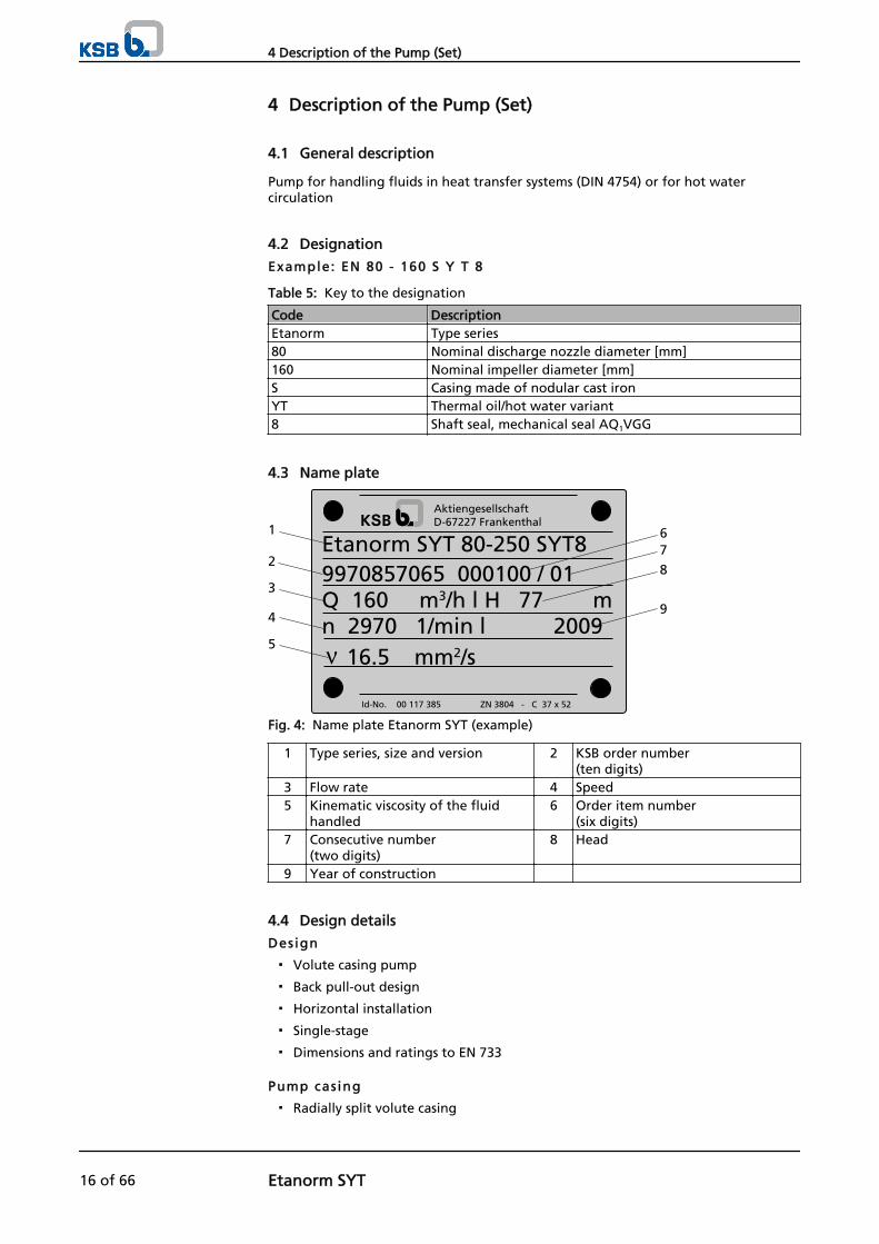
Example: EN 80 - 160 S Y T 8
Table 5: Key to the designation
Code DescriptionEtanorm Type series80 Nominal discharge nozzle diameter [mm]160 Nominal impeller diameter [mm]S Casing made of nodular cast ironYT Thermal oil/hot water variant8 Shaft seal, mechanical seal AQ1VGG
4.3 Name plate
Etanorm SYT 80-250 SYT89970857065 000100 / 01Q 160 m3/h l H 77 m
16.5 mm2/sn 2970 1/min l 2009
AktiengesellschaftD-67227 Frankenthal
Id-No. 00 117 385 ZN 3804 - C 37 x 52
1
2
5
4
3
9
8
76
Fig. 4: Name plate Etanorm SYT (example)
1 Type series, size and version 2 KSB order number(ten digits)
3 Flow rate 4 Speed5 Kinematic viscosity of the fluid
handled6 Order item number
(six digits)7 Consecutive number
(two digits)8 Head
9 Year of construction
4.4 Design details
Design
▪ Volute casing pump
▪ Back pull-out design
▪ Horizontal installation
▪ Single-stage
▪ Dimensions and ratings to EN 733
Pump cas ing
▪ Radially split volute casing
4 Description of the Pump (Set)
16 of 66 Etanorm SYT

▪ Replaceable casing wear rings
▪ Volute casing with integrally cast pump feet
Impel ler type
▪ Closed radial impeller with multiply curved vanes
Bearings
Motor-end bearing:
▪ Radial ball bearing
▪ Grease lubrication
Table 6: Rolling element bearing
Shaft unit Code25 6306-2RS/C3 PCP-LLG35 6309-2RS/C3 PCP-LLG55 6311-2RS/C3 PCP-LLG
▪ Grease-packed for life (high melting point grease), with sealing washers on bothsides
Pump-end bearing:
▪ Plain bearing
▪ Product-lubricated
Shaft seal
▪ Standardised mechanical seal to EN 12756
Optional:
▪ Double mechanical seal
4.5 Configuration and function
1 2 3 4 5
6 7 8 9 10
Fig. 5: Sectional drawing
4 Description of the Pump (Set)
Etanorm SYT 17 of 66

1 Clearance gap 2 Discharge nozzle3 Casing cover 4 Shaft5 Bearing bracket 6 Suction nozzle7 Impeller 8 Plain bearing9 Shaft seal 10 Rolling element bearing, motor
end
The pump is designed with an axial fluid inlet and a radial outlet. The hydraulicsystem runs in its own bearings and is connected to the motor by a shaft coupling.
The fluid enters the pump axially via the suction nozzle (6) and is acceleratedoutward by the rotating impeller (7). In the flow passage of the pump casing thekinetic energy of the fluid is converted into pressure energy. The fluid is pumped tothe discharge nozzle (2), where it leaves the pump. The clearance gap (1) preventsany fluid from flowing back from the casing to the suction nozzle. At the rear side ofthe impeller, the shaft (4) enters the casing via the casing cover (3). The shaft passagethrough the bearing bracket is sealed towards the atmosphere with a shaft seal (9).The shaft runs in a plain bearing and a rolling element bearing (8 and 10); thebearings are supported by a bearing bracket (5) linked with the pump casing and/orcasing cover.
The pump is sealed by a standardised mechanical seal.If the pump is fitted with a double mechanical seal, the pump is connected to aquench pot. The unpressurised quench liquid supply serves to prevent any leakage ofthe fluid handled towards the atmosphere. It also prevents any contact between thefluid and the lubricating grease of the rolling element bearing, especially for fluidswhich have a tendency to creep.
4.6 Noise characteristics
Table 7: Sound pressure level measured at surfaces LpA2) 3)
Rated powerinput
PN
[kW]
Pump Pump set1450 rpm
[dB]2900 rpm
[dB]1450 rpm
[dB]2900 rpm
[dB]
0.55 47 48 55 640.75 48 50 56 661.1 50 52 57 661.5 52 54 58 672.2 54 56 59 673 55 57 60 684 57 59 61 68
5.5 59 61 62 707.5 60 62 64 7111 62 64 65 7315 64 66 67 74
18.5 65 67 68 7522 66 68 69 7630 67 70 70 7737 68 71 71 7845 69 72 73 7855 70 73 74 7975 72 75 75 8090 73 76 76 81
110 74 77 77 81
Design
Function
Sealing
2) Spatial average to ISO 3744 and EN 12639. Applies to non-cavitating pump operation in the range Q/Qopt = 0.8 - 1.1. Ifnoise levels are to be guaranteed: Add +3 dB for measuring and constructional tolerance.
3) Increase for 60 Hz operation: 3500 rpm, +3 dB; 1750 rpm +1 dB
4 Description of the Pump (Set)
18 of 66 Etanorm SYT
4.7 Scope of supply
Depending on the model, the following items are included in the scope of supply:
▪ Pump
▪ Surface-cooled IEC three-phase current squirrel-cage motor
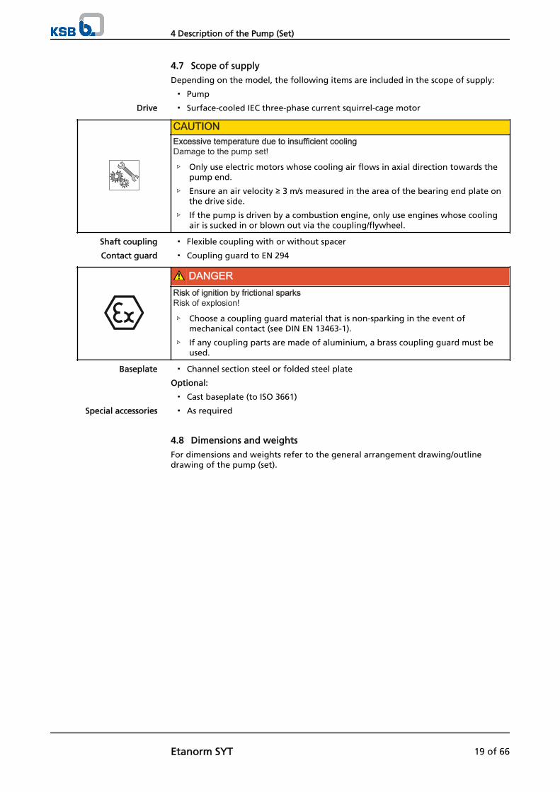
CAUTIONExcessive temperature due to insufficient coolingDamage to the pump set!
▷ Only use electric motors whose cooling air flows in axial direction towards thepump end.
▷ Ensure an air velocity ≥ 3 m/s measured in the area of the bearing end plate onthe drive side.
▷ If the pump is driven by a combustion engine, only use engines whose coolingair is sucked in or blown out via the coupling/flywheel.
▪ Flexible coupling with or without spacer
▪ Coupling guard to EN 294
DANGERRisk of ignition by frictional sparksRisk of explosion!
▷ Choose a coupling guard material that is non-sparking in the event ofmechanical contact (see DIN EN 13463-1).
▷ If any coupling parts are made of aluminium, a brass coupling guard must beused.
▪ Channel section steel or folded steel plate
Optional:
▪ Cast baseplate (to ISO 3661)
▪ As required
4.8 Dimensions and weights
For dimensions and weights refer to the general arrangement drawing/outlinedrawing of the pump (set).
Drive
Shaft coupling
Contact guard
Baseplate
Special accessories
4 Description of the Pump (Set)
Etanorm SYT 19 of 66

5 Installation at Site
5.1 Safety regulations
DANGERImproper installation in potentially explosive atmospheresExplosion hazard!Damage to the pump set!
▷ Comply with the applicable local explosion protection regulations.
▷ Observe the information in the data sheet and on the name plates of pump andmotor.
5.2 Checks to be carried out prior to installation
Place of instal lat ion
WARNINGInstallation on mounting surface which is unsecured and cannot support the loadPersonal injury and damage to property!
▷ Use a concrete of compressive strength class C12/15 which meets therequirements of exposure class XC1 to EN 206-1.
▷ The mounting surface must have set and must be completely horizontal andeven.
▷ Observe the weights indicated.
1. Check the structural requirements. All structural work required must have been prepared in accordance with thedimensions stated in the outline drawing/general arrangement drawing.
5.3 Installing the pump set
Always install the pump set in horizontal position.
DANGERExcessive temperatures due to improper installationExplosion hazard!
▷ Install the pump in horizontal position to ensure self-venting of the pump.
5.3.1 Installation on the foundation
12
43Fig. 6: Fitting the shims
1 Bolt-to-bolt clearance 2 Shim3 Shim for (1) > 800 mm 4 Foundation bolt
✓ The foundation has the required strength and characteristics.
5 Installation at Site
20 of 66 Etanorm SYT

✓ The foundation has been prepared in accordance with the dimensions given inthe outline drawing/general arrangement drawing.
1. Position the pump set on the foundation and align it with the help of a spiritlevel placed on the shaft and discharge nozzle.Permissible deviation: 0.2 mm/m
2. Use shims (2) for height compensation, if necessary. Always fit shims, if any, immediately to the left and right of the foundation bolts(4) between the baseplate/foundation frame and the foundation.For a bolt-to-bolt clearance (1) > 800 mm fit additional shims (3) halfwaybetween the bolt holes. All shims must lie perfectly flush.
3. Insert the foundation bolts (4) into the holes provided.
4. Use concrete to set the foundation bolts (4) into the foundation.
5. Wait until the concrete has set firmly, then align the baseplate.
6. Tighten the foundation bolts (4) evenly and firmly.
NOTEFor baseplates more than 400 mm wide it is recommended to grout the baseplate withlow-shrinkage concrete.
NOTEFor baseplates made of grey cast iron it is recommended to grout the baseplate with low-shrinkage concrete.
NOTEFor low-noise operation contact KSB to check whether the pump set can be installed onanti-vibration mounts.
5.3.2 Installation without foundation
4
1
2
3
Fig. 7: Adjusting the levelling elements
1, 3 Locknut 2 Levelling nut4 Levelling element
✓ The installation surface has the required strength and characteristics.
1. Position the pump set on the levelling elements (4) and align it with the help of aspirit level (on the shaft/discharge nozzle).
2. To adjust any differences in height, loosen the bolts and locknuts (1, 3) of thelevelling elements (4).
3. Turn the levelling nut (2) until any differences in height have been compensated.
4. Re-tighten the locknuts (1, 3) at the levelling elements (4).
5 Installation at Site
Etanorm SYT 21 of 66

5.4 Piping
5.4.1 Connecting the piping
DANGERImpermissible loads acting on the pump nozzlesDanger to life from leakage of hot, toxic, corrosive or flammable fluids!
▷ Do not use the pump as an anchorage point for the piping.
▷ Anchor the pipelines in close proximity to the pump and connect them withouttransmitting any stresses or strains.
▷ Observe the permissible forces and moments at the pump nozzles. (⇨ Section5.4.2 Page 23)
▷ Take appropriate measures to compensate thermal expansion of the piping.
CAUTIONIncorrect earthing during welding work at the pipingDestruction of rolling element bearings (pitting effect)!
▷ Never earth the electric welding equipment on the pump or baseplate.
▷ Prevent current flowing through the rolling element bearings.
NOTEIt is recommended to install check and shut-off elements in the system, depending on thetype of plant and pump. However, such elements must not obstruct proper drainage orhinder disassembly of the pump.
✓ The suction lift line has been laid with a rising slope, the suction head line with adownward slope towards the pump.
✓ A flow stabilisation section having a length equivalent to at least twice thediameter of the suction flange has been provided upstream of the suction flange.
✓ The nominal diameters of the pipelines are at least equal to the nominaldiameters of the pump nozzles.
✓ Adapters to larger diameters have a diffuser angle of approx. 8° to preventexcessive pressure losses.
✓ The pipelines have been anchored in close proximity to the pump and connectedwithout transmitting any stresses or strains.
1. Thoroughly clean, flush and blow through all vessels, pipelines and connections(especially of new installations).
2. Before installing the pump in the piping, remove the flange covers on the suctionand discharge nozzles of the pump.
CAUTIONWelding beads, scale and other impurities in the pipingDamage to the pump!
▷ Free the piping from any impurities.
▷ If necessary, install a filter.
▷ Comply with the instructions set out in (⇨ Section 7.2.2.3 Page 41) .
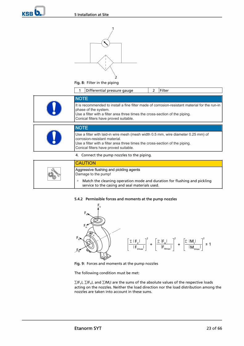
3. If required, install a filter in the piping (see drawing: Filter in the piping).
5 Installation at Site
22 of 66 Etanorm SYT
1
2Fig. 8: Filter in the piping
1 Differential pressure gauge 2 Filter
NOTEIt is recommended to install a fine filter made of corrosion-resistant material for the run-inphase of the system.Use a filter with a filter area three times the cross-section of the piping.Conical filters have proved suitable.
NOTEUse a filter with laid-in wire mesh (mesh width 0.5 mm, wire diameter 0.25 mm) ofcorrosion-resistant material.Use a filter with a filter area three times the cross-section of the piping.Conical filters have proved suitable.
4. Connect the pump nozzles to the piping.
CAUTIONAggressive flushing and pickling agentsDamage to the pump!
▷ Match the cleaning operation mode and duration for flushing and picklingservice to the casing and seal materials used.
5.4.2 Permissible forces and moments at the pump nozzles
FV
FVmax
2FH
FHmax
2
Mtmax
Mt
2
+ + - 1
FV
FH
FH
FVFH
FH
Fig. 9: Forces and moments at the pump nozzles
The following condition must be met:
∑IFVI, ∑IFHI, and ∑IMtI are the sums of the absolute values of the respective loadsacting on the nozzles. Neither the load direction nor the load distribution among thenozzles are taken into account in these sums.
5 Installation at Site
Etanorm SYT 23 of 66
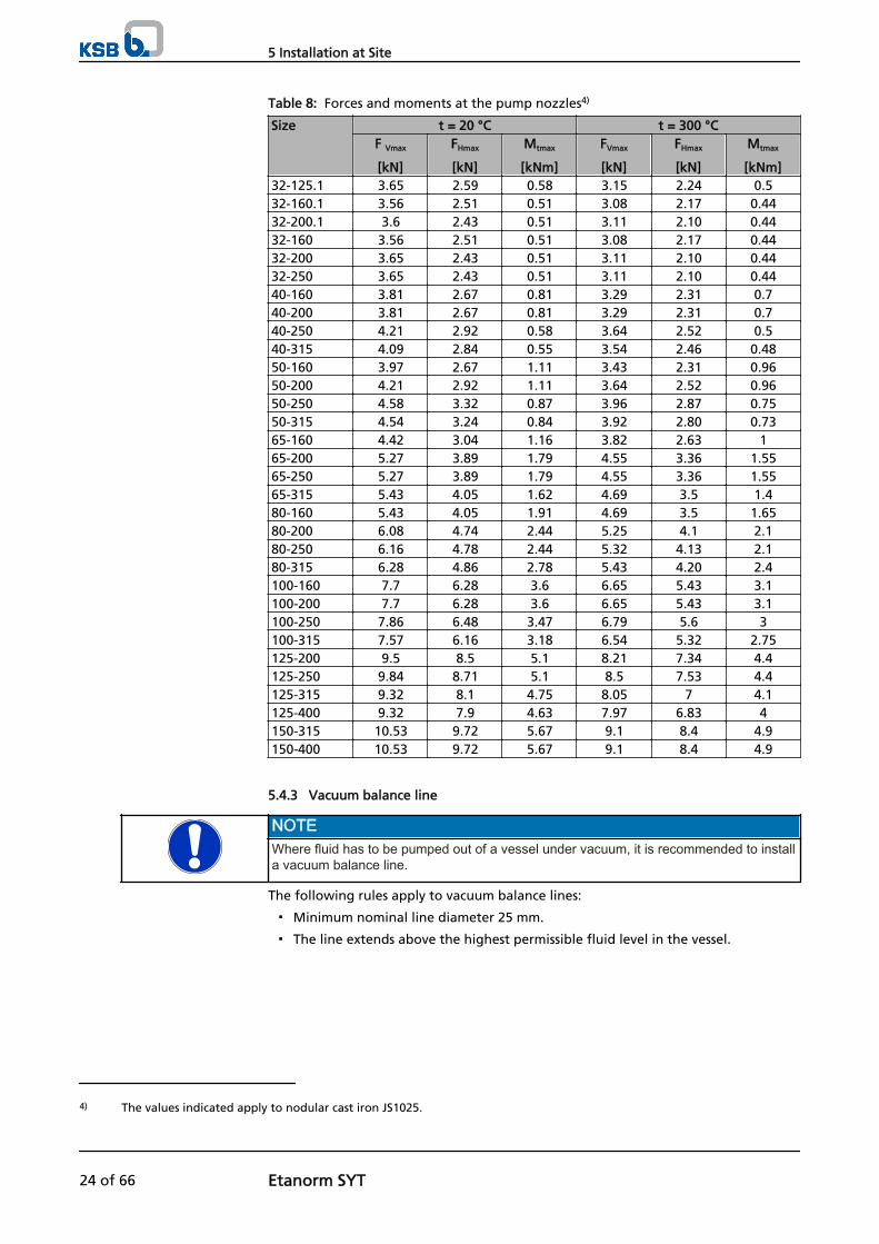
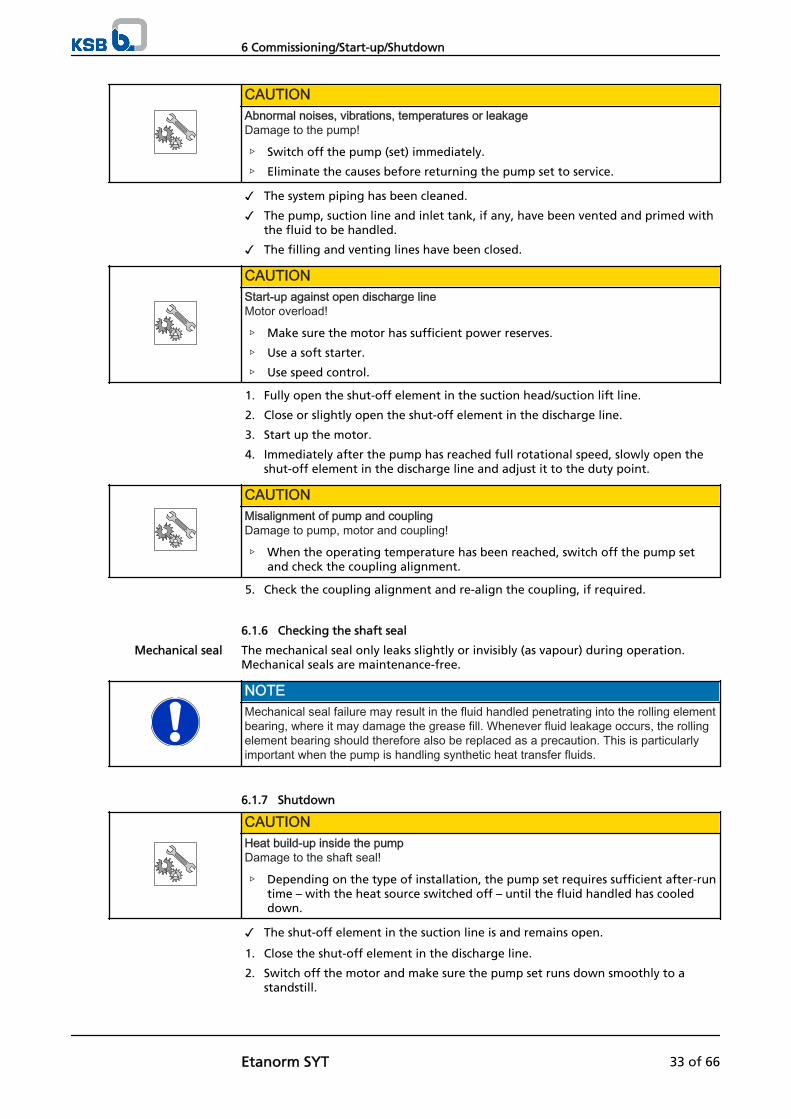
Table 8: Forces and moments at the pump nozzles4)
Size t = 20 °C t = 300 °CF Vmax
[kN]
FHmax
[kN]
Mtmax
[kNm]
FVmax
[kN]
FHmax
[kN]
Mtmax
[kNm]32-125.1 3.65 2.59 0.58 3.15 2.24 0.532-160.1 3.56 2.51 0.51 3.08 2.17 0.4432-200.1 3.6 2.43 0.51 3.11 2.10 0.4432-160 3.56 2.51 0.51 3.08 2.17 0.4432-200 3.65 2.43 0.51 3.11 2.10 0.4432-250 3.65 2.43 0.51 3.11 2.10 0.4440-160 3.81 2.67 0.81 3.29 2.31 0.740-200 3.81 2.67 0.81 3.29 2.31 0.740-250 4.21 2.92 0.58 3.64 2.52 0.540-315 4.09 2.84 0.55 3.54 2.46 0.4850-160 3.97 2.67 1.11 3.43 2.31 0.9650-200 4.21 2.92 1.11 3.64 2.52 0.9650-250 4.58 3.32 0.87 3.96 2.87 0.7550-315 4.54 3.24 0.84 3.92 2.80 0.7365-160 4.42 3.04 1.16 3.82 2.63 165-200 5.27 3.89 1.79 4.55 3.36 1.5565-250 5.27 3.89 1.79 4.55 3.36 1.5565-315 5.43 4.05 1.62 4.69 3.5 1.480-160 5.43 4.05 1.91 4.69 3.5 1.6580-200 6.08 4.74 2.44 5.25 4.1 2.180-250 6.16 4.78 2.44 5.32 4.13 2.180-315 6.28 4.86 2.78 5.43 4.20 2.4100-160 7.7 6.28 3.6 6.65 5.43 3.1100-200 7.7 6.28 3.6 6.65 5.43 3.1100-250 7.86 6.48 3.47 6.79 5.6 3100-315 7.57 6.16 3.18 6.54 5.32 2.75125-200 9.5 8.5 5.1 8.21 7.34 4.4125-250 9.84 8.71 5.1 8.5 7.53 4.4125-315 9.32 8.1 4.75 8.05 7 4.1125-400 9.32 7.9 4.63 7.97 6.83 4150-315 10.53 9.72 5.67 9.1 8.4 4.9150-400 10.53 9.72 5.67 9.1 8.4 4.9
5.4.3 Vacuum balance line
NOTEWhere fluid has to be pumped out of a vessel under vacuum, it is recommended to installa vacuum balance line.
The following rules apply to vacuum balance lines:
▪ Minimum nominal line diameter 25 mm.
▪ The line extends above the highest permissible fluid level in the vessel.
4) The values indicated apply to nodular cast iron JS1025.
5 Installation at Site
24 of 66 Etanorm SYT

1 2
5
43
6Fig. 10: Vacuum balance system
1 Vessel under vacuum 2 Vacuum balance line3 Shut-off element 4 Swing check valve5 Main shut-off element 6 Vacuum-tight shut-off element
NOTEAn additional line (from the pump discharge nozzle to the balance line) fitted with a shut-off element facilitates venting of the pump before start-up.
5.4.4 Auxiliary connections
CAUTIONFailure to use or incorrect use of auxiliary connections (e.g. barrier fluid, flushing liquid,etc.)Malfunction of the pump!
▷ Refer to the general arrangement drawing, the piping layout and pumpmarkings (if any) for the dimensions and locations of auxiliary connections.
▷ Use the auxiliary connections provided.
Fig. 11: Connections 24E and 24A
24 A Outlet quench liquid 24 E Inlet quench liquid
For designs with double mechanical seal, use connections 24A and 24E to connect thepump set to the quench system.Connect the quench pot in accordance with the manufacturer's instructions.
Double mechanical seal
5 Installation at Site
Etanorm SYT 25 of 66

5.5 Protective equipment
DANGERAn explosive atmosphere could form due to insufficient ventingExplosion hazard!
▷ Make sure the space between the casing cover/discharge cover and the bearingcover is sufficiently vented.
WARNINGThe volute casing and casing/discharge cover take on the same temperature as the fluidhandledRisk of burns!
▷ Insulate the volute casing.
▷ Fit protective equipment.
CAUTIONHeat build-up in the bearing bracketDamage to the bearing!
▷ Never insulate the bearing bracket, bearing bracket lantern and casing cover.
5.6 Checking the coupling alignment
DANGERImpermissible temperatures at the coupling or bearings caused by misalignment of thecouplingExplosion hazard!
▷ Make sure that the coupling is correctly aligned at all times.
CAUTIONMisalignment of pump and motor shaftsDamage to pump, motor and coupling!
▷ Always check the coupling after the pump has been installed and connected tothe piping.
▷ Also check the coupling of pump sets supplied with pump and motor mountedon the same baseplate.
BA
A B
a) b)
B
B
A
A
1
1 2 21
1
Fig. 12: a) Checking the coupling alignment and b) Aligning a spacer-type coupling
1 Straight-edge 2 Wedge gauge
✓ The coupling guard and step guard, if any, have been removed.
5 Installation at Site
26 of 66 Etanorm SYT

1. Loosen the support foot and re-tighten it without transmitting any stresses andstrains.
2. Place the straight-edge axially on both coupling halves.
3. Leave the straight-edge in this position and turn the coupling by hand. The coupling is correctly aligned if the distances A and B to the respective shaftsare the same at all points around the circumference.The radial and axial deviation of both coupling halves must not exceed ≤ 0.1 mm,during standstill as well as at operating temperature and under inlet pressure.
4. Check the distance between the two coupling halves around the circumference. The coupling is correctly aligned if the distance between the two coupling halvesis the same at all points around the circumference.The radial and axial deviation of both coupling halves must not exceed ≤ 0.1 mm,during standstill as well as at operating temperature and under inlet pressure.
5. Re-install the coupling guard and step guard, if any.
5.7 Aligning the pump and motor
After having installed the pump set and connected the piping, check the couplingalignment and, if required, re-align the pump set (at the motor).
5.7.1 Motors with levelling screw
1
3
2
Fig. 13: Motor with levelling screw
1 Hexagon head bolt 2 Levelling screw3 Locknut
✓ The coupling guard and step guard, if any, have been removed.
1. Check the coupling alignment.
2. Unscrew the hexagon head bolts (1) at the motor and the locknuts (3) at thebaseplate.
3. Turn the levelling screws (2) by hand or by means of an open-jawed wrench untilthe coupling alignment is correct and all motor feet rest squarely on thebaseplate.
4. Re-tighten the hexagon head bolts (1) at the motor and the locknuts (3) at thebaseplate.
5. Check that the coupling and shaft can easily be rotated by hand.
WARNINGUnprotected rotating couplingRisk of injury by rotating shafts!
▷ Always operate the pump set with a coupling guard.If the customer specifically requests not to include a coupling guard in KSB'sdelivery, then the operator must supply one!
▷ Observe all relevant regulations for selecting a coupling guard.
5 Installation at Site
Etanorm SYT 27 of 66

DANGERRisk of ignition by frictional sparksExplosion hazard!
▷ Choose a coupling guard material that is non-sparking in the event ofmechanical contact (see DIN EN 13463-1).
6. Re-install the coupling guard and step guard, if any.
7. Check the distance between coupling and coupling guard.The coupling and coupling guard must not come into contact.
5.7.2 Motors without levelling screw
Any differences in the centre heights of the pump and motor shafts are compensatedby means of shims.
1Fig. 14: Pump set with shim
1 Shim
✓ The coupling guard and step guard, if any, have been removed.
1. Check the coupling alignment.
2. Unscrew the hexagon head bolts at the motor.
3. Insert shims underneath the motor feet until the difference in shaft centre heighthas been compensated.
4. Re-tighten the hexagon head bolts.
5. Check that the coupling and shaft can easily be rotated by hand.
WARNINGUnprotected rotating couplingRisk of injury by rotating shafts!
▷ Always operate the pump set with a coupling guard.If the customer specifically requests not to include a coupling guard in KSB'sdelivery, then the operator must supply one!
▷ Observe all relevant regulations for selecting a coupling guard.
DANGERRisk of ignition by frictional sparksExplosion hazard!
▷ Choose a coupling guard material that is non-sparking in the event ofmechanical contact (see DIN EN 13463-1).
6. Re-install the coupling guard and step guard, if any.
7. Check the distance between coupling and coupling guard.The coupling guard must not touch the coupling.
5 Installation at Site
28 of 66 Etanorm SYT

5.8 Electrical connection
DANGERIncorrect electrical installationExplosion hazard!
▷ For electrical installation, also observe the requirements of IEC 60079-14.
▷ Always connect explosion-proof motors via a motor protection switch.
DANGERWork on the pump set by unqualified personnelDanger of death from electric shock!
▷ Always have the electrical connections installed by a trained and qualifiedelectrician.
▷ Observe regulations IEC 60364 and, for explosion-proof models, EN 60079.
WARNINGIncorrect connection to the mainsDamage to the mains network, short circuit!
▷ Observe the technical specifications of the local energy supply companies.
1. Check the available mains voltage against the data on the motor name plate.
2. Select an appropriate start-up method.
NOTEIt is recommended to fit a motor protection device.
5.9 Checking the direction of rotation
DANGERTemperature increase resulting from contact between rotating and stationarycomponentsExplosion hazard!Damage to the pump set!
▷ Never check the direction of rotation by starting up the unfilled pump set.
▷ Separate the pump from the motor to check the direction of rotation.
WARNINGHands or objects inside the pump casingRisk of injuries, damage to the pump!
▷ Never insert your hands or any other objects into the pump.
▷ Check that the inside of the pump is free from any foreign objects.
CAUTIONIncorrect direction of rotation with non-reversible mechanical sealDamage to the mechanical seal and leakage!
▷ Separate the pump from the motor to check the direction of rotation.
5 Installation at Site
Etanorm SYT 29 of 66

CAUTIONDrive and pump running in the wrong direction of rotationDamage to the pump!
▷ Refer to the arrow indicating the direction of rotation on the pump.
▷ Check the direction of rotation. If required, check the electrical connection andcorrect the direction of rotation.
The correct direction of rotation of motor and pump is clockwise (seen from themotor end).
1. Start the motor and stop it again immediately to determine the motor's directionof rotation.
2. Check the direction of rotation. The motor's direction of rotation must match the arrow indicating the directionof rotation on the pump.
3. If the motor is running in the wrong direction of rotation, check the electricalconnection of the motor and the control system, if necessary.
5 Installation at Site
30 of 66 Etanorm SYT

6 Commissioning/Start-up/Shutdown
6.1 Commissioning/start-up
6.1.1 Prerequisites for commissioning/start-up
Before starting up the pump set make sure that the following requirements are met:
▪ The pump set has been properly connected to the electric power supply and isequipped with all protection devices.
▪ The pump and the bearing bracket have been primed with the fluid to behandled. (⇨ Section 6.1.3 Page 31)
▪ The quench system, if any, has been filled with the quench liquid. (⇨ Section 6.1.2Page 31)
▪ The direction of rotation has been checked. (⇨ Section 5.9 Page 29)
▪ All auxiliary connections required are connected and operational.
▪ The lubricants have been checked. (⇨ Section 7.2.3 Page 41)
▪ After prolonged shutdown of the pump (set), the activities described in (⇨Section 6.4 Page 36) have been carried out.
6.1.2 Quench liquid supply
The quench liquid has to be compatible with and suitable for mixing with the fluidhandled.
For synthetic heat transfer oils, it is advisable to use a mineral oil based thermal fluidor a different mineral oil as the quench liquid.Heat transfer oils of the diphyl group are not suitable for use as quench liquids.
6.1.3 Priming and venting the pump
DANGERRisk of potentially explosive atmosphere inside the pumpExplosion hazard!
▷ Before starting up the pump, vent the suction line and the pump and primethem with the fluid to be handled.
CAUTIONIncreased wear due to dry runningDamage to the pump set!
▷ Never operate the pump set without liquid fill.
▷ Never close the shut-off element in the suction line and/or supply line duringpump operation.
NOTEIn the run-in phase of the system, it is recommended to vent the pump repeatedly via thescrew plug on the bearing bracket.
1. Remove screw plug 903.1 (connection 6D) to prime and vent the bearinghousing.
2. Vent the pump and suction line and prime both with the fluid to be handled.The pump can be primed with the fluid handled from the system via the inletline.
3. Fully open the shut-off element in the suction line.
4. Fully open all auxiliary feed lines (barrier fluid, flushing liquid, etc), if applicable.
Permissible quench liquids
6 Commissioning/Start-up/Shutdown
Etanorm SYT 31 of 66

5. Open the shut-off element, if any, in the vacuum balance line and close thevacuum-tight shut-off element, if any. (⇨ Section 5.4.3 Page 24)
WARNINGHot water escaping under pressure when the vent plug is openedRisk of electric shock!Risk of scalding!
▷ Protect the electric components against escaping fluid.
▷ Wear protective clothing (e.g. gloves).
NOTEFor design-inherent reasons a remaining gas volume in the hydraulic system cannot beexcluded after the pump has been primed for commissioning/start-up. However, once themotor is started up the pumping effect will immediately fill this volume with the fluidhandled.
6. Close the vent hole (connection 6D) with screw plug 903.1.
6.1.4 Final check
1. Remove the coupling guard and step guard, if any.
2. Check the coupling alignment; re-align the coupling, if required. (⇨ Section 5.6Page 26)
3. Check that the coupling and shaft can easily be rotated by hand.
4. Re-install the coupling guard and step guard, if any.
5. Check the distance between coupling and coupling guard.The coupling guard must not touch the coupling.
NOTEThe coupling alignment check must be repeated after the pump has reached operatingtemperature.
6.1.5 Start-up
DANGERThe permissible pressure and temperature limits will be exceeded if the pump isoperated with the suction and discharge lines closed.Explosion hazard!Leakage of hot or toxic fluids!
▷ Never operate the pump with the shut-off elements in the suction line and/ordischarge line closed.
▷ Only start up the pump set with the discharge-side gate valve slightly or fullyopen.
DANGERExcessive temperatures due to dry running or excessive gas content in the fluid handledExplosion hazard!Damage to the pump set!
▷ Never operate the pump set without liquid fill.
▷ Prime the pump as specified.
▷ Always operate the pump within the permissible operating range.
6 Commissioning/Start-up/Shutdown
32 of 66 Etanorm SYT
CAUTIONAbnormal noises, vibrations, temperatures or leakageDamage to the pump!
▷ Switch off the pump (set) immediately.
▷ Eliminate the causes before returning the pump set to service.
✓ The system piping has been cleaned.
✓ The pump, suction line and inlet tank, if any, have been vented and primed withthe fluid to be handled.
✓ The filling and venting lines have been closed.
CAUTIONStart-up against open discharge lineMotor overload!
▷ Make sure the motor has sufficient power reserves.
▷ Use a soft starter.
▷ Use speed control.
1. Fully open the shut-off element in the suction head/suction lift line.
2. Close or slightly open the shut-off element in the discharge line.
3. Start up the motor.
4. Immediately after the pump has reached full rotational speed, slowly open theshut-off element in the discharge line and adjust it to the duty point.
CAUTIONMisalignment of pump and couplingDamage to pump, motor and coupling!
▷ When the operating temperature has been reached, switch off the pump setand check the coupling alignment.
5. Check the coupling alignment and re-align the coupling, if required.
6.1.6 Checking the shaft seal
The mechanical seal only leaks slightly or invisibly (as vapour) during operation.Mechanical seals are maintenance-free.
NOTEMechanical seal failure may result in the fluid handled penetrating into the rolling elementbearing, where it may damage the grease fill. Whenever fluid leakage occurs, the rollingelement bearing should therefore also be replaced as a precaution. This is particularlyimportant when the pump is handling synthetic heat transfer fluids.
6.1.7 Shutdown
CAUTIONHeat build-up inside the pumpDamage to the shaft seal!
▷ Depending on the type of installation, the pump set requires sufficient after-runtime – with the heat source switched off – until the fluid handled has cooleddown.
✓ The shut-off element in the suction line is and remains open.
1. Close the shut-off element in the discharge line.
2. Switch off the motor and make sure the pump set runs down smoothly to astandstill.
Mechanical seal
6 Commissioning/Start-up/Shutdown
Etanorm SYT 33 of 66
NOTEIf the discharge line is equipped with a non-return or check valve, the shut-off elementmay remain open.
For prolonged shutdown periods:
1. Close the shut-off element in the suction line.
2. Close the auxiliary connections. If the fluid handled is fed in under vacuum, also supply the shaft seal with barrierfluid during standstill.
CAUTIONRisk of freezing during prolonged pump shutdown periodsDamage to the pump!
▷ Drain the pump and the cooling/heating chambers (if any) or otherwise protectthem against freezing.
6.2 Operating limits
DANGERNon-compliance with operating limits for pressure, temperature, fluid handled and speedExplosion hazard!Hot or toxic fluid could escape!
▷ Comply with the operating data indicated in the data sheet.
▷ Avoid prolonged operation against a closed shut-off element.
▷ Never operate the pump at temperatures exceeding those specified in the datasheet or on the name plate unless the written consent of the manufacturer hasbeen obtained.
6.2.1 Ambient temperature
Observe the following parameters and values during operation:
Table 9: Permissible ambient temperatures
Permissible ambient temperature ValueMaximum 40 °CMinimum See data sheet.
CAUTIONOperation outside the permissible ambient temperatureDamage to the pump (set)!
▷ Observe the specified limits for permissible ambient temperatures.
NOTEAfter commissioning, increased temperatures may occur at grease-lubricated rollingelement bearings due to the running-in process. The final bearing temperature is onlyreached after a certain period of operation (up to 48 hours depending on the conditions).
6 Commissioning/Start-up/Shutdown
34 of 66 Etanorm SYT
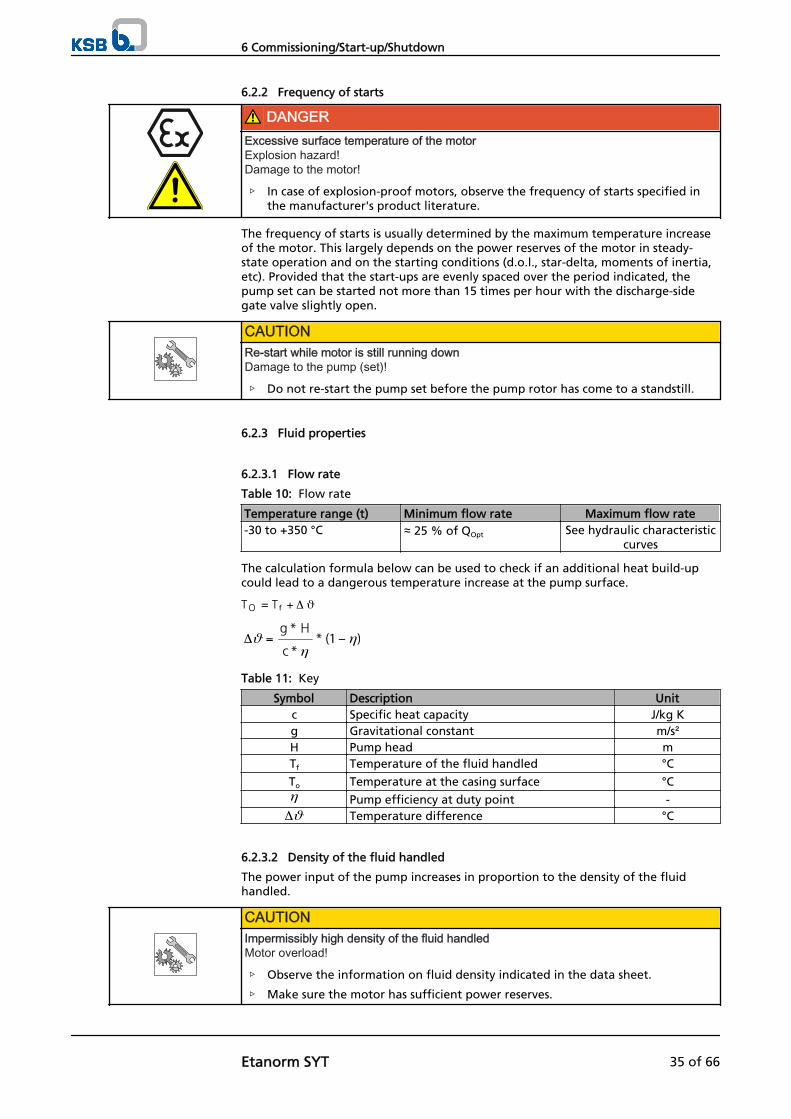
6.2.2 Frequency of starts
DANGERExcessive surface temperature of the motorExplosion hazard!Damage to the motor!
▷ In case of explosion-proof motors, observe the frequency of starts specified inthe manufacturer's product literature.
The frequency of starts is usually determined by the maximum temperature increaseof the motor. This largely depends on the power reserves of the motor in steady-state operation and on the starting conditions (d.o.l., star-delta, moments of inertia,etc). Provided that the start-ups are evenly spaced over the period indicated, thepump set can be started not more than 15 times per hour with the discharge-sidegate valve slightly open.
CAUTIONRe-start while motor is still running downDamage to the pump (set)!
▷ Do not re-start the pump set before the pump rotor has come to a standstill.
6.2.3 Fluid properties
6.2.3.1 Flow rate
Table 10: Flow rate
Temperature range (t) Minimum flow rate Maximum flow rate-30 to +350 °C ≈ 25 % of QOpt See hydraulic characteristic
curves
The calculation formula below can be used to check if an additional heat build-upcould lead to a dangerous temperature increase at the pump surface.
Table 11: Key
Symbol Description Unitc Specific heat capacity J/kg Kg Gravitational constant m/s²H Pump head mTf Temperature of the fluid handled °C
To Temperature at the casing surface °C
Pump efficiency at duty point -Temperature difference °C
6.2.3.2 Density of the fluid handled
The power input of the pump increases in proportion to the density of the fluidhandled.
CAUTIONImpermissibly high density of the fluid handledMotor overload!
▷ Observe the information on fluid density indicated in the data sheet.
▷ Make sure the motor has sufficient power reserves.
6 Commissioning/Start-up/Shutdown
Etanorm SYT 35 of 66
6.2.3.3 Abrasive fluids
Do not exceed the maximum permissible solids content specified in the data sheet.When the pump handles fluids containing abrasive substances, increased wear of thehydraulic system, plain bearing and shaft seal are to be expected. In this case, reducethe intervals commonly recommended for servicing and maintenance.
6.2.4 Permissible speed
Table 12: Permissible speed for pump control systems with continuously variablespeed adjustment
n min
[rpm]nmax
[rpm]800 -
6.3 Shutdown/storage/preservation
6.3.1 Measures to be taken for shutdown
The pump (set) remains instal led
✓ Sufficient fluid is supplied for the operation check run of the pump.
1. Start up the pump (set) regularly between once a month and once every threemonths for approximately five minutes during prolonged shutdown periods. This will prevent the formation of deposits within the pump and the pumpintake area.
The pump (set) i s removed from the pipe and stored
✓ The pump has been properly drained (⇨ Section 7.3 Page 41) and the safetyinstructions for dismantling the pump have been observed. (⇨ Section 7.4.1 Page42)
1. Spray-coat the inside wall of the pump casing, and in particular the impellerclearance areas, with a preservative.
2. Spray the preservative through the suction and discharge nozzles.It is advisable to then close the pump nozzles (e.g. with plastic caps or similar).
3. Oil or grease all blank parts and surfaces of the pump (with silicone-free oil orgrease, food-approved, if required) to protect them against corrosion.Observe the additional instructions. (⇨ Section 3.3 Page 13)
If the pump set is to be stored temporarily, only preserve the wetted componentsmade of low alloy materials. Commercially available preservatives can be used for thispurpose. Observe the manufacturer's instructions for application/removal.
Observe any additional instructions and information provided. (⇨ Section 3 Page 13)
6.4 Returning to service
For returning the pump to service observe the sections on commissioning/start-up (⇨Section 6.1 Page 31) and the operating limits. (⇨ Section 6.2 Page 34)
In addition, carry out all servicing/maintenance operations before returning thepump (set) to service. (⇨ Section 7 Page 38)
WARNINGFailure to re-install or re-activate protective devicesRisk of personal injury from moving parts or escaping fluid!
▷ As soon as the work is completed, re-install and/or re-activate any safety-relevant and protective devices.
6 Commissioning/Start-up/Shutdown
36 of 66 Etanorm SYT
NOTEIf the pump has been out of service for more than one year, replace all elastomer seals.
6 Commissioning/Start-up/Shutdown
Etanorm SYT 37 of 66

7 Servicing/Maintenance
7.1 Safety regulations
DANGERImproperly serviced pump setExplosion hazard!Damage to the pump set!
▷ Service the pump set regularly.
▷ Prepare a maintenance schedule with special emphasis on lubricants, shaft sealand coupling.
The operator ensures that all maintenance, inspection and installation work isperformed by authorised, qualified specialist personnel who are thoroughly familiarwith the manual.
WARNINGUnintentional starting of pump setRisk of injury by moving parts!
▷ Make sure that the pump set cannot be started up unintentionally.
▷ Always make sure the electrical connections are disconnected before carryingout work on the pump set.
WARNINGFluids posing a health hazard and/or hot fluidsRisk of personal injury!
▷ Observe all relevant laws.
▷ When draining the fluid take appropriate measures to protect persons and theenvironment.
▷ Decontaminate pumps which handle fluids posing a health hazard.
A regular maintenance schedule will help avoid expensive repairs and contribute totrouble-free, reliable operation of the pump (set) with a minimum of maintenanceexpenditure and work.
NOTEAll maintenance, service and installation work can be carried out by KSB Service. Findyour contact in the attached "Addresses" booklet or on the internet at www.ksb.com/contact".
Never use force when dismantling and reassembling the pump set.
7.2 Maintenance/inspection
7.2.1 Supervision of operation
DANGERFormation of an explosive atmosphere inside the pumpExplosion hazard!
▷ The pump internals in contact with the fluid to be handled, including the sealchamber and auxiliary systems must be filled with the fluid to be handled at alltimes.
▷ Provide sufficient inlet pressure.
▷ Provide an appropriate monitoring system.
7 Servicing/Maintenance
38 of 66 Etanorm SYT

DANGERExcessive temperatures as a result of bearings running hot or defective bearing sealsExplosion hazard!Fire hazard!Damage to the pump set!
▷ Regularly check the rolling element bearings for running noises.
CAUTIONIncreased wear due to dry runningDamage to the pump set!
▷ Never operate the pump set without liquid fill.
▷ Never close the shut-off element in the suction line and/or supply line duringpump operation.
CAUTIONImpermissibly high temperature of fluid handledDamage to the pump!
▷ Prolonged operation against a closed shut-off element is not permitted (heatingup of the fluid).
▷ Observe the temperature limits in the data sheet and in the section onoperating limits. (⇨ Section 6.2 Page 34)
While the pump is in operation, observe and check the following:
▪ The pump must run quietly and free from vibrations at all times.
▪ Check the shaft seal.
▪ Check the static seals for leakage.
▪ Check the rolling element bearings for running noises.Vibrations, noise and an increase in power input occurring during unchangedoperating conditions indicate wear.
▪ Monitor the correct functioning of any auxiliary connections.
▪ Monitor the stand-by pump.To make sure that the stand-by pumps are ready for operation, start them uponce a week.
▪ Check the quench liquid level.Make sure the quench pot always contains sufficient quench liquid.
NOTEIf the liquid level in the quench pot rises, fluid from the pump has mixed with the quenchliquid, which indicates leakage at the pump-end mechanical seal. During start-up it isnormal for the liquid level in the quench pot to rise until the operating temperature hasbeen reached.
NOTEIf the liquid level in the quench pot drops rapidly, this indicates leakage at the drive-endmechanical seal. In this case, the quench liquid could mix with the grease of rollingelement bearing 321 and affect lubrication. Check the rolling element bearing andreplace it, if required.
▪ Monitor the rolling element bearing temperature.The bearing temperature must not exceed 90 °C (measured on the outside of thebearing bracket).
7 Servicing/Maintenance
Etanorm SYT 39 of 66
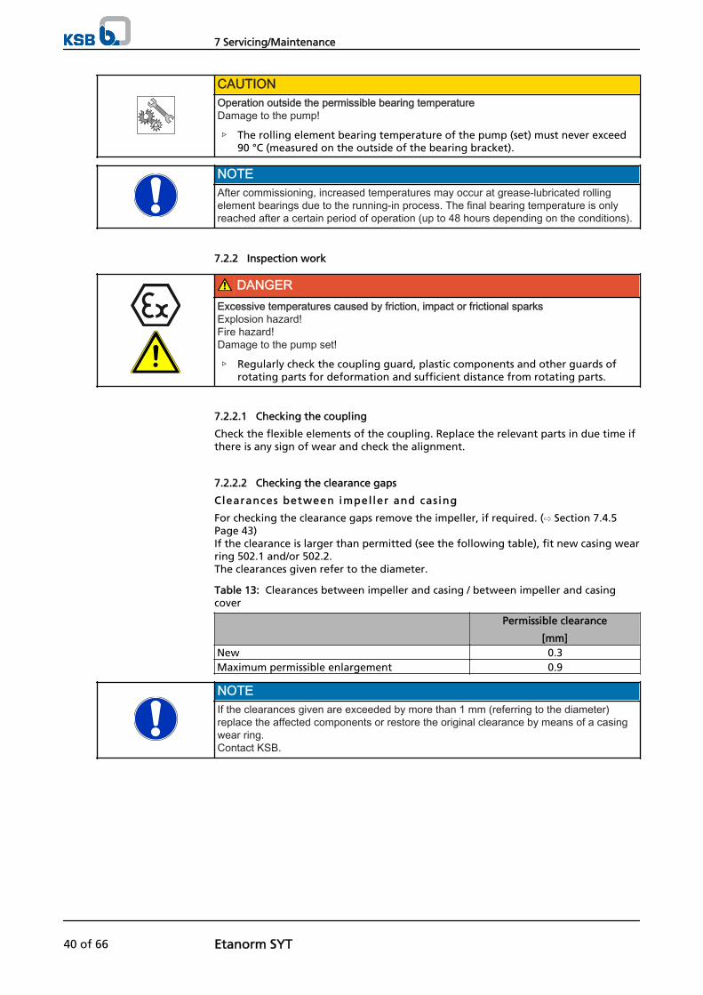
CAUTIONOperation outside the permissible bearing temperatureDamage to the pump!
▷ The rolling element bearing temperature of the pump (set) must never exceed90 °C (measured on the outside of the bearing bracket).
NOTEAfter commissioning, increased temperatures may occur at grease-lubricated rollingelement bearings due to the running-in process. The final bearing temperature is onlyreached after a certain period of operation (up to 48 hours depending on the conditions).
7.2.2 Inspection work
DANGERExcessive temperatures caused by friction, impact or frictional sparksExplosion hazard!Fire hazard!Damage to the pump set!
▷ Regularly check the coupling guard, plastic components and other guards ofrotating parts for deformation and sufficient distance from rotating parts.
7.2.2.1 Checking the coupling
Check the flexible elements of the coupling. Replace the relevant parts in due time ifthere is any sign of wear and check the alignment.
7.2.2.2 Checking the clearance gaps
Clearances between impel ler and cas ing
For checking the clearance gaps remove the impeller, if required. (⇨ Section 7.4.5Page 43)If the clearance is larger than permitted (see the following table), fit new casing wearring 502.1 and/or 502.2.The clearances given refer to the diameter.
Table 13: Clearances between impeller and casing / between impeller and casingcover
Permissible clearance
[mm]New 0.3Maximum permissible enlargement 0.9
NOTEIf the clearances given are exceeded by more than 1 mm (referring to the diameter)replace the affected components or restore the original clearance by means of a casingwear ring. Contact KSB.
7 Servicing/Maintenance
40 of 66 Etanorm SYT

Plain bearing c learances
Table 14: Plain bearing clearances in mm
Shaft unit Permissible clearance
[mm]New Maximum permissible
enlargement25 0.08 - 0.13 0.3535 0.08 - 0.13 0.455 0.08 - 0.13 0.4
7.2.2.3 Cleaning filters
CAUTIONInsufficient inlet pressure due to clogged filter in the suction lineDamage to the pump!
▷ Monitor contamination of filter with suitable means (e.g. differential pressuregauge).
▷ Clean filter in appropriate intervals.
7.2.3 Lubricating the rolling element bearing
DANGERExcessive temperatures as a result of bearings running hot or defective bearing sealsExplosion hazard!Fire hazard!Damage to the pump set!
▷ Regularly check the bearing seal.
The bearings are delivered packed for life with a special high-temperature grease.
7.2.3.1 Intervals
Under normal operating conditions the grease-packed rolling element bearing willrun for 15,000 operating hours. Under unfavourable operating conditions (e.g. highroom temperature, high atmospheric humidity, dust-laden air, aggressive industrialatmosphere etc.), check the rolling element bearing earlier and replace it, if required.
7.2.4 Lubricating the plain bearing
The pump-end plain bearing is lubricated by the fluid handled. It is maintenance-free.
7.3 Drainage/cleaning
WARNINGFluids posing a health hazard and/or hot fluidsHazard to persons and the environment!
▷ Collect and properly dispose of flushing liquid and any liquid residues.
▷ Wear safety clothing and a protective mask, if required.
▷ Observe all legal regulations on the disposal of fluids posing a health hazard.
1. Use connection 6B to drain the fluid handled (see drawing of auxiliaryconnections).
2. Always flush the pump if it has been used for handling noxious, explosive hot orother hazardous fluids.
7 Servicing/Maintenance
Etanorm SYT 41 of 66

Always flush and clean the pump before transporting it to the workshop. Providea cleaning record for the pump.
7.4 Dismantling the pump set
7.4.1 General information/Safety regulations
WARNINGUnqualified personnel performing work on the pump (set)Risk of injury!
▷ Always have repair and maintenance work performed by specially trained,qualified personnel.
WARNINGHot surfaceRisk of injury!
▷ Allow the pump set to cool down to ambient temperature.
WARNINGImproper lifting/moving of heavy assemblies or componentsPersonal injury and damage to property!
▷ Use suitable transport devices, hoisting equipment and lifting tackle to moveheavy assemblies or components.
Observe the general safety instructions and information. (⇨ Section 7.1 Page 38)
For any work on the motor, observe the instructions of the relevant motormanufacturer.
For dismantling and reassembly observe the exploded views and the generalassembly drawing.
NOTEAll maintenance, service and installation work can be carried out by KSB Service. Findyour contact in the attached "Addresses" booklet or on the internet at www.ksb.com/contact".
DANGERInsufficient preparation of work on the pump (set)Risk of injury!
▷ Properly shut down the pump set. (⇨ Section 6.1.7 Page 33)
▷ Close the shut-off elements in suction and discharge line.
▷ Drain the pump and release the pump pressure. (⇨ Section 7.3 Page 41)
▷ Close any auxiliary connections.
▷ Allow the pump set to cool down to ambient temperature.
NOTEAfter a prolonged period of operation the individual components may be hard to pull offthe shaft. If this is the case, use a brand name penetrating agent and/or - if possible - anappropriate pull-off device.
7.4.2 Preparing the pump set
1. Interrupt the power supply and secure the pump against unintentional start-up.
2. Disconnect and remove all auxiliary pipework.
7 Servicing/Maintenance
42 of 66 Etanorm SYT

3. Remove the coupling guard.
4. Remove the coupling spacer, if any.
7.4.3 Dismantling the motor
NOTEOn pump sets with spacer-type couplings, the back pull-out unit can be removed whilethe motor remains bolted to the baseplate.
WARNINGMotor tipping overRisk of squashing hands and feet!
▷ Suspend or support the motor to prevent it from tipping over.
1. Disconnect the motor from the power supply.
2. Unbolt the motor from the baseplate.
3. Shift the motor to separate it from the pump.
7.4.4 Removing the back pull-out unit
✓ The notes and steps stated in (⇨ Section 7.4.1 Page 42) to (⇨ Section 7.4.3 Page43) have been observed/carried out.
✓ On pump sets without spacer-type coupling, the motor has been removed.
WARNINGBack pull-out unit tipping overRisk of squashing hands and feet!
▷ Suspend or support the bearing bracket at the pump end.
1. If required, suspend or support bearing bracket 330 to prevent it from tippingover.
2. Unbolt support foot 183 from the baseplate.
3. Undo nuts 920.1 at the volute casing.
4. Pull the back pull-out unit out of the volute casing.
5. Remove and dispose of joint ring 411.4.
WARNINGThin metal foil used as carrier material in joint ringsRisk of injury (cuts)!
▷ Wear protective clothing.
▷ Always use an appropriate tool to remove joint rings.
6. Place the back pull-out unit on a clean and level surface.
7.4.5 Removing the impeller
✓ The notes and steps stated in (⇨ Section 7.4.1 Page 42) to (⇨ Section 7.4.4 Page43) have been observed/carried out.
✓ The back pull-out unit is kept in a clean and level assembly area.
1. Undo impeller nut 920.3 (right-hand thread).
2. Remove impeller 230 with an impeller removal device.
3. Place impeller 230 on a clean and level surface.
4. Remove keys 940.1 from shaft 210.
7 Servicing/Maintenance
Etanorm SYT 43 of 66

7.4.6 Dismantling the shaft seal
7.4.6.1 Removing the pump assembly from the bearing bracket — all shaft units
✓ The notes and steps stated in (⇨ Section 7.4.1 Page 42) to (⇨ Section 7.4.5 Page43) have been observed/carried out.
✓ The back pull-out unit is kept in a clean and level assembly area.
1. Undo nuts 920.2.
2. Pull bearing bracket 330 out of discharge cover 163.
WARNINGThin metal foil used as carrier material in joint ringsRisk of injury (cuts)!
▷ Wear protective clothing.
▷ Always use an appropriate tool to remove joint rings.
3. Remove and dispose of joint ring 411.3.
4. Remove bearing cover 360.
5. Remove circlip 932.2.
6. Press shaft 210 out of bearing bracket 330.
7.4.6.1.1 Dismantling a single mechanical seal — shaft units 25 and 35
✓ The notes and steps stated in (⇨ Section 7.4.1 Page 42) to (⇨ Section 7.4.6.1 Page44) have been observed/carried out.
1. Remove circlip 932.1 and support disc 550.2.
2. Pull bearing 321 off shaft 210.
3. Remove support disc 550.1 and mating ring holder 476.
4. Press the mating ring of mechanical seal 433 out of mating ring holder 476.
5. Remove the rotating assembly of mechanical seal 433 (primary ring) from shaft210.
7.4.6.1.2 Dismantling a single mechanical seal — shaft unit 55
✓ The notes and steps stated in (⇨ Section 7.4.1 Page 42) to (⇨ Section 7.4.6.1 Page44) have been observed/carried out.
1. Remove circlip 932.4 and support disc 550.5.
2. Remove the rotating assembly of mechanical seal 433 (primary ring) from theshaft.
3. Remove mating ring holder 476.
4. Press the mating ring of mechanical seal 433 out of mating ring holder 476.
7.4.6.1.3 Dismantling a double mechanical seal — shaft units 25 and 35
✓ The notes and steps stated in (⇨ Section 7.4.1 Page 42) to (⇨ Section 7.4.6.1 Page44) have been observed/carried out.
1. Remove circlip 932.1 and support disc 550.2.
2. Pull bearing 321 off shaft 210.
3. Remove support disc 550.1 and mating ring holder 476.
4. Press the mating ring of mechanical seal 433.2 out of mating ring holder 476.
5. Remove spacer sleeve 525.
6. Remove the rotating part of mechanical seal 433.2 (primary ring) from the shaft.
7 Servicing/Maintenance
44 of 66 Etanorm SYT
7. Remove circlip 932.5 and support disc 550.6.
8. Remove mating ring holder 476.1.
9. Press the mating ring of mechanical seal 433.1 out of mating ring holder 476.1.
10. Remove the rotating part of mechanical seal 433.1 (primary ring) from the shaft.
7.4.6.1.4 Dismantling a double mechanical seal — shaft unit 55
✓ The notes and steps stated in (⇨ Section 7.4.1 Page 42) to (⇨ Section 7.4.6.1 Page44) have been observed/carried out.
1. Remove circlip 932.4 and support disc 550.5.
2. Remove the rotating assembly of mechanical seal 433.1 (primary ring) from theshaft.
3. Remove mating ring holder 476.1.
4. Press the mating ring of mechanical seal 433.1 out of mating ring holder 476.1.
5. Remove spacer sleeve 525.
6. Remove circlip 932.5 and support disc 550.6.
7. Remove the rotating assembly of mechanical seal 433.2 (primary ring) from theshaft.
8. Remove mating ring holder 476.
9. Press the mating ring of mechanical seal 433.2 out of mating ring holder 476.
7.4.7 Removing the plain bearing
Removing the carbon bearing
✓ The notes and steps stated in (⇨ Section 7.4.1 Page 42) to (⇨ Section 7.4.6.1 Page44) have been observed/carried out.
1. Push plain bearing 310 out of bearing bracket 330 from the drive end.
Removing the S iC bearing
✓ The notes and steps stated in (⇨ Section 7.4.1 Page 42) to (⇨ Section 7.4.6.1 Page44) have been observed/carried out.
1. Remove circlip 932.7.
2. Pull bearing sleeve 529 off shaft 210.
3. Remove circlip 932.6.
4. Push bush 540.1 and bearing cartridge 381 out of bearing bracket 330 from thedrive end.
7.5 Reassembling the pump set
7.5.1 General information/Safety regulations
WARNINGImproper lifting/moving of heavy assemblies or componentsPersonal injury and damage to property!
▷ Use suitable transport devices, hoisting equipment and lifting tackle to moveheavy assemblies or components.
7 Servicing/Maintenance
Etanorm SYT 45 of 66
CAUTIONImproper reassemblyDamage to the pump!
▷ Reassemble the pump (set) in accordance with the general rules of soundengineering practice.
▷ Use original spare parts only.
Always reassemble the pump in accordance with the corresponding general assemblydrawing or exploded view.
Check O-rings for any damage and replace by new O-rings, if required.
Always use new gaskets, making sure that they have the same thickness as the oldones.
Always fit gaskets of asbestos-free materials or graphite without using lubricants(e.g. copper grease, graphite paste).
Avoid the use of assembly adhesives, if possible.
Should an assembly adhesive be required after all, use a commercially availablecontact adhesive (e.g. "Pattex") or sealant (e.g. HYLOMAR or Epple 33).
Only apply adhesive at selected points and in thin layers.
Never use quick-setting adhesives (cyanoacrylate adhesives).
Coat the locating surfaces of the individual components with graphite or similarbefore reassembly.
For reassembly, tighten all screws and bolts as specified in this manual. (⇨ Section 7.6Page 49)
7.5.2 Installing the plain bearing
Fitt ing the carbon bear ing
✓ The individual parts are kept in a clean and level assembly area.
✓ All disassembled parts have been cleaned and checked for wear.
✓ Any damaged or worn parts have been replaced by original spare parts.
✓ The sealing surfaces have been cleaned.
1. Press plain bearing 310 carefully into bearing bracket 330 until it will not go anyfurther.
F itt ing the S iC bearing
✓ The individual parts are kept in a clean and level assembly area.
✓ All disassembled parts have been cleaned and checked for wear.
✓ Any damaged or worn parts have been replaced by original spare parts.
✓ The sealing surfaces have been cleaned.
1. Push bearing sleeve 529 onto shaft 210.
2. Fit circlip 932.7.
3. Fit O-rings 412.3 at both sides of bearing cartridge 381.
4. Carefully press bearing bush 381 into bearing bracket 330.
5. Fit bush 540.1.
6. Fit circlip 932.6.
7.5.3 Installing the shaft seal
The following rules must be observed when installing the mechanical seal:
▪ Work cleanly and accurately.
Sequence
Dichtungen
Assembly adhesives
Tightening torques
Installing the mechanicalseal
7 Servicing/Maintenance
46 of 66 Etanorm SYT

▪ Only remove the protective wrapping of the contact faces immediately beforeinstallation takes place.
▪ Prevent any damage to the sealing surfaces or O-rings.
7.5.3.1 Installing a single mechanical seal — shaft units 25 and 35
1. Clean the mating ring location in mating ring holder 476.
2. Carefully insert the mating ring of mechanical seal 433 into mating ring holder476. Press it in evenly.
3. Slide the rotating assembly of the mechanical seal (primary ring) onto shaft 210.
4. Fit mating ring holder 476 with O-Ring 412.1.
5. Fit support disc 550.1.
6. Press radial ball bearing 321 onto the shaft and secure it with support disc 550.2and circlip 932.1.
7.5.3.2 Installing a single mechanical seal — shaft unit 55
1. Clean the mating ring location in mating ring holder 476.
2. Carefully insert the mating ring of mechanical seal 433 into mating ring holder476.Make sure to apply pressure evenly.
3. Fit mating ring holder 476 with O-Ring 412.1.
4. Slide the rotating assembly of the mechanical seal (primary ring) onto shaft 210.
5. Fit support disc 550.5 and circlip 932.4.
7.5.3.3 Installing a double mechanical seal — shaft units 25 and 35
1. Clean the mating ring location of mating ring holders 476 and 476.1.
2. Insert the mating rings of mechanical seals 433.1 and 433.2 into mating ringholders 476 and 476.1.Press them in evenly.
3. Slide the rotating assembly of the mechanical seal 433.1 (primary ring) onto shaft210.
4. Fit mating ring holder 476.1 with O-Ring 412.2.
5. Fit circlip 932.5 and support disc 550.6.
6. Slide the rotating assembly of mechanical seal 433.2 (primary ring) onto shaft210.
7. Fit spacer sleeve 525.
8. Fit mating ring holder 476 with O-Ring 412.1.
9. Fit support disc 550.1.
10. Press radial ball bearing 321 onto the shaft and secure it with support disc 550.2and circlip 932.1.
7.5.3.4 Installing a double mechanical seal — shaft unit 55
1. Clean the mating ring location of mating ring holders 476 and 476.1.
2. Insert the mating rings of mechanical seals 433.1 and 433.2 into mating ringholders 476 and 476.1. Make sure to apply pressure evenly.
3. Fit mating ring holder 476 with O-ring 412.1.
4. Slide the rotating part of mechanical seal 433.2 (primary ring) onto shaft 210.
5. Fit circlip 932.5 and support disc 550.6.
7 Servicing/Maintenance
Etanorm SYT 47 of 66
6. Fit spacer sleeve 525 with mating ring holder 476.1 and O-ring 412.2.
7. Slide the rotating part of mechanical seal 433.1 (primary ring) onto shaft 210.
8. Fit circlip 932.4 and support disc 550.5.
7.5.3.5 Installing the shaft assembly in the bearing bracket — all shaft units
1. Carefully press the shaft assembly into bearing bracket 330.
2. Fit circlip 932.2.
3. Fit bearing cover 360.
7.5.4 Fitting the impeller
✓ The notes and steps stated in (⇨ Section 7.5.1 Page 45) to (⇨ Section 7.5.3 Page46) have been observed/carried out.
✓ The assembled bearing bracket as well as the individual parts are kept in a cleanand level assembly area.
✓ All disassembled parts have been cleaned and checked for wear.
✓ Any damaged or worn parts have been replaced by original spare parts.
✓ The sealing surfaces have been cleaned.
1. Insert key 940.1 and push impeller 230 onto shaft 210.
2. Fasten impeller nut 920.3, spring washer 930 and disc 550.3, if any (see table:Tightening torques for screwed connections at the pump (⇨ Section 7.6 Page49)).
7.5.5 Installing the back pull-out unit
WARNINGBack pull-out unit tipping overRisk of squashing hands and feet!
▷ Suspend or support the bearing bracket at the pump end.
✓ The notes and steps stated in (⇨ Section 7.5.1 Page 45) to (⇨ Section 7.5.4 Page48) have been observed/carried out.
✓ Any damaged or worn parts have been replaced by original spare parts.
✓ The sealing surfaces have been cleaned.
✓ For back pull-out units supplied without coupling: Fit the coupling in accordancewith the manufacturer's instructions.
1. Insert new joint ring 411.4 into volute casing 102.
2. If required, prevent the back pull-out unit from tipping over, e.g. by suspendingor supporting it. Then push it into volute casing 102.
3. Tighten nut 920.1 at the volute casing. Observe the tightening torques.
4. Fasten support foot 183 to the baseplate with a foundation bolt.
7.5.6 Mounting the motor
NOTESteps 1 and 2 do not apply to versions with spacer-type coupling.
1. Shift the motor to connect it to the pump via the coupling.
2. Fasten the motor to the baseplate.
3. Align pump and motor. (⇨ Section 5.7 Page 27)
7 Servicing/Maintenance
48 of 66 Etanorm SYT
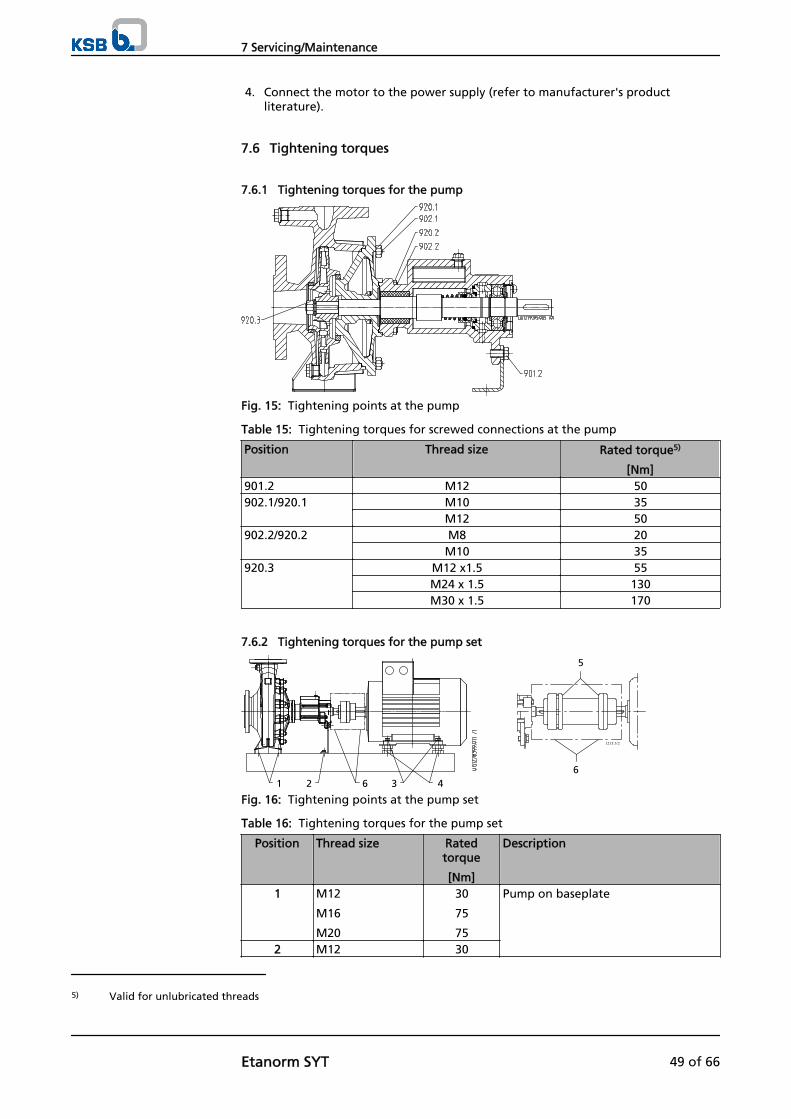
4. Connect the motor to the power supply (refer to manufacturer's productliterature).
7.6 Tightening torques
7.6.1 Tightening torques for the pump
Fig. 15: Tightening points at the pump
Table 15: Tightening torques for screwed connections at the pump
Position Thread size Rated torque5)
[Nm]901.2 M12 50902.1/920.1 M10 35
M12 50902.2/920.2 M8 20
M10 35920.3 M12 x1.5 55
M24 x 1.5 130M30 x 1.5 170
7.6.2 Tightening torques for the pump set
1215:5/2
1 2 3 466
5
Fig. 16: Tightening points at the pump set
Table 16: Tightening torques for the pump set
Position Thread size Ratedtorque
[Nm]
Description
1 M12
M16
M20
30
75
75
Pump on baseplate
2 M12 30
5) Valid for unlubricated threads
7 Servicing/Maintenance
Etanorm SYT 49 of 66

Position Thread size Ratedtorque
[Nm]
Description
3 M24 x 1.5
M36 x 1.5
140
140
Levelling screws in baseplate
4 M6
M8
M10
M12
M16
M20
M24
10
10
15
30
75
140
140
Motor on baseplate or
motor on levelling screws or shims
5 M6
M8
M10
13
18
44
Coupling (only for spacer-typecoupling made by Flender)
6 M6 10 Coupling guard
7.7 Spare parts stock
7.7.1 Ordering spare parts
Always quote the following data when ordering replacement or spare parts:
▪ Type series
▪ Material variant
▪ Size
▪ Seal code
▪ KSB order number
▪ Order item number
▪ Consecutive number
▪ Year of construction
Refer to the name plate for all data. (⇨ Section 4.3 Page 16)
Also supply the following data:
▪ Description
▪ Part No.
▪ Quantity of spare parts
▪ Shipping address
▪ Mode of dispatch (freight, mail, express freight, air freight)
Refer to the exploded view or general assembly drawing for part numbers anddescriptions. (⇨ Section 9.1 Page 56)
7.7.2 Recommended spare parts stock for 2 years' operation to DIN 24296
Table 17: Quantity of spare parts for recommended spare parts stock
Part No. Description Number of pumps (including stand-by pumps)2 3 4 5 6 and 7 8 and 9 10 and
more210 Shaft 1 1 1 2 2 2 20 %230 Impeller6) 1 1 1 2 2 2 20 %
6) Including casing wear ring 502.2
7 Servicing/Maintenance
50 of 66 Etanorm SYT

Part No. Description Number of pumps (including stand-by pumps)2 3 4 5 6 and 7 8 and 9 10 and
more310 Plain bearing 2 3 4 5 7 9 100 %321 Radial ball bearing 1 1 2 2 2 3 25 %330 Bearing bracket7) - - - - - 1 2433 Mechanical seal8) 1 1 2 2 3 3 25 %502.1/.2 Casing wear ring 1 1 1 2 2 2 20 %411.3/.4 Joint ring 4 6 8 8 9 12 150 %412 O-ring9) 4 6 8 8 9 10 100 %- Torque-transmitting
coupling elements (set)1 1 2 2 3 4 30 %
7) Complete bearing bracket. Example of a pump set with single mechanical seal and carbon plain bearing: shaft 210, plainbearing 310, radial ball bearing 321, bearing bracket 330, bearing cover 360, joint ring 411.1, O-ring 412.1, mechanical seal433, mating ring holder 476, disc 550.1/.2/.3/.5, stud 902.2, screw plug 903.1, pan head screw 914, hexagon nut 920.2/.3,spring washer 930, circlip 932.1/.2/.4, key 940.1/.2
8) For double mechanical seals double the quantity.9) For double mechanical seal: parts 412.1 and 412.2
7 Servicing/Maintenance
Etanorm SYT 51 of 66

7.7.3 Interchangeability of pump components
Components featuring the same number in a column are interchangeable.
Table 18: Interchangeability of pump componentsEt
ano
rm S
YT
Shaf
t u
nit
Etab
loc
SYT
Etal
ine
SYT
Description
Dis
char
ge
cove
r
Sup
po
rt f
oo
t10)
Shaf
t 10
)
Imp
elle
r
Plai
n b
eari
ng
Dee
p-g
roo
ve b
all b
eari
ng
10)
Bea
rin
g b
rack
et10
)
Bea
rin
g h
ou
sin
g11
)
Bea
rin
g c
ove
r10)
Mec
han
ical
sea
l10)
12)
Mec
han
ical
sea
l11)
Seal
co
ver11
)
Mat
ing
rin
g h
old
er10
)
Cas
ing
wea
r ri
ng
, su
ctio
n s
ide
Cas
ing
wea
r ri
ng
, dis
char
ge
sid
e
Part No.
163
183
210
230
310
321
330
350
360
433
433
471
476
502.
1
502.
2
32-125.5 25 32-125.1/. - 1 1 1 O O 1 1 1 1 1 3 1 1 1 X32-160.1 25 32-160.1/. 40-160/.. 1 2 1 1 O 1 1 1 1 1 3 1 1 1 332-200.1 25 32-200.1/. 40-200/.. 2 3 1 2 O 1 1 1 1 1 3 1 1 1 332-160 25 32-160/.. 50-160/.. 1 2 1 1 O 1 1 1 1 1 3 1 1 1 332-200 25 32-200/.. 50-200/.. 2 3 1 2 O 1 1 1 1 1 3 1 1 1 332-250 25 - - 3 4 1 O 2 1 1 - 1 1 - - 1 1 1040-160 25 40-160/.. 65-160/.. 1 2 1 O O 1 1 1 1 1 3 1 1 2 340-200 25 40-200/.. 65-200/.. 2 3 1 O O 1 1 1 1 1 3 1 1 O 340-250 25 - - 3 4 1 O 2 1 1 - 1 1 - - 1 2 1040-315 35 - - O 7 2 O 3 2 2 - 2 2 - - 2 2 1350-160 25 50-160/.. 80-160/.. 1 3 1 O O 1 1 1 1 1 3 1 1 3 350-200 25 50-200/.. 80-200/.. 2 3 1 O O 1 1 1 1 1 3 1 1 3 350-250 25 - - 3 4 1 O 2 1 1 - 1 1 - - 1 3 1050-315 35 - - 7 7 2 O 3 2 2 - 2 2 - - 2 4 1165-160 25 65-160/.. 100-160/.. 4 3 1 O O 1 1 1 1 1 3 1 1 4 565-200 25 65-200/.. - O 4 1 O O 1 1 - 1 1 - - 1 4 565-250 35 - - O 5 2 O 3 2 2 - 2 2 - - 2 5 1365-315 35 - - 7 7 2 O 3 2 2 - 2 2 - - 2 5 1180-160 25 80-160/.. 100-170/.. 4 4 1 O O 1 1 - 1 1 - - 1 6 580-200 35 - - 5 O 2 O 3 2 2 - 2 2 - - 2 6 1180-250 35 - - 6 5 2 O 3 2 2 - 2 2 - - 2 6 1180-315 35 - - 7 6 2 O 3 2 2 - 2 2 - - 2 6 11100-160 35 - - 5 5 2 O 3 2 2 - 2 2 - - 2 7 11100-200 35 - - 5 5 2 O 3 2 2 - 2 2 - - 2 7 11100-250 35 - - 6 7 2 O 3 2 2 - 2 2 - - 2 7 11100-315 35 - - 7 6 2 O 3 2 2 - 2 2 - - 2 7 11125-200 35 - - O 6 2 O 3 2 2 - 2 2 - - 2 8 O125-250 35 - - O 6 2 O 3 2 2 - 2 2 - - 2 8 O125-315 55 - - 8 9 3 O 3 3 3 - 3 2 - - 3 8 12125-400 55 - - 9 8 3 O 3 3 3 - 3 2 - - 3 8 12150-315 55 - - 8 9 3 O 3 3 3 - 3 2 - - 3 9 12150-400.1 55 - - 10 8 3 O 3 3 3 - 3 2 - - 3 9 -
10) Etanorm SYT only11) Etabloc SYT/Etaline SYT only12) Single mechanical seal 433 not interchangeable with double mechanical seal 433.1/.2
7 Servicing/Maintenance
52 of 66 Etanorm SYT
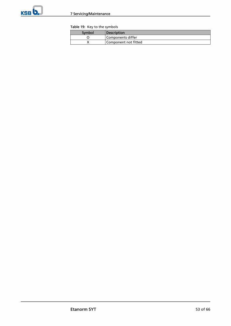
Table 19: Key to the symbols
Symbol DescriptionO Components differX Component not fitted
7 Servicing/Maintenance
Etanorm SYT 53 of 66
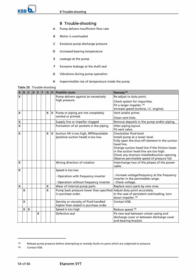
8 Trouble-shootingPump delivers insufficient flow rate
Motor is overloaded
Excessive pump discharge pressure
Increased bearing temperature
Leakage at the pump
Excessive leakage at the shaft seal
Vibrations during pump operation
Impermissible rise of temperature inside the pump
Table 20: Trouble-shooting
A B C D E F G H Possible cause Remedy13)
X Pump delivers against an excessivelyhigh pressure.
Re-adjust to duty point.
Check system for impurities.Fit a larger impeller.14)
Increase speed (turbine, I.C. engine).X X X Pump or piping are not completely
vented or primed.Vent and/or prime.
Clean vent hole.X Supply line or impeller clogged Remove deposits in the pump and/or piping.X Formation of air pockets in the piping Alter piping layout.
Fit vent valve.X X X Suction lift is too high, NPSHavailable
(positive suction head) is too low.Check/alter fluid level.Install pump at a lower level.Fully open the shut-off element in the suctionhead line.Change suction head line if the friction lossesin the suction head line are too high.Check any strainers installed/suction opening.Observe permissible speed of pressure fall.
X Wrong direction of rotation Interchange two of the phases of the powercable.
X Speed is too low
- Operation with frequency inverter
- Operation without frequency inverter
- Increase voltage/frequency at the frequencyinverter in the permissible range.- Check voltage.
X X Wear of internal pump parts Replace worn parts by new ones. X X Pump back pressure lower than specified
in purchase order.Adjust duty point accurately. In the case of persistent overloading, turndown impeller.14)
X Density or viscosity of fluid handledhigher than stated in purchase order
Contact KSB.
X X Speed is too high Reduce speed.14)
X Defective seal Fit new seal between volute casing anddischarge cover or between discharge coverand bearing bracket.
A
B
C
D
E
F
G
H
13) Release pump pressure before attempting to remedy faults on parts which are subjected to pressure.14) Contact KSB.
8 Trouble-shooting
54 of 66 Etanorm SYT

A B C D E F G H Possible cause Remedy13)
X Joint ring not pre-loaded sufficiently Increase pre-loading of the joint ring atoperating temperature:
1. Close the valves on the discharge andsuction side.
2. Allow the pump set to cool down to atemperature below the boiling point ofthe fluid handled.
3. Re-tighten hexagon nuts 920.1 and 920.2at the discharge cover.
4. Start up the pump set. (⇨ Section 6 Page31)
X Worn shaft seal Fit new shaft seal.Check flushing liquid/barrier fluid.
X Pump runs rough Correct suction conditions.Re-align the pump set.Re-balance the impeller.Increase pressure at the pump suction nozzle.
X X X Pump set misaligned Re-align the pump set. X X X Pump warped or sympathetic vibrations
in the pipingCheck the piping connections and securefixing of pump; if required, reduce distancesbetween the pipe clamps.Fix the pipelines using anti-vibration material.
X Increased axial thrust14) Clean balancing holes in the impeller.Replace the casing wear rings.
X Non-compliance with specified couplingdistance
Correct distance according to generalarrangement drawing.
X X Motor running on two phases only Replace the defective fuse.Check the electric cable connections.
X Rotor out of balance Clean the impeller.Re-balance the impeller.
X Defective bearing Fit new bearing. X X X Flow rate is too low Increase minimum flow rate.
13) Release pump pressure before attempting to remedy faults on parts which are subjected to pressure.
8 Trouble-shooting
Etanorm SYT 55 of 66
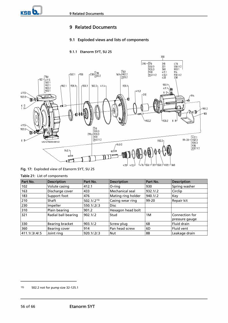
9 Related Documents
9.1 Exploded views and lists of components
9.1.1 Etanorm SYT, SU 25
UG1278203:001/2
Fig. 17: Exploded view of Etanorm SYT, SU 25
Table 21: List of components
Part No. Description Part No. Description Part No. Description102 Volute casing 412.1 O-ring 930 Spring washer163 Discharge cover 433 Mechanical seal 932.1/.2 Circlip183 Support foot 476 Mating ring holder 940.1/.2 Key210 Shaft 502.1/.215) Casing wear ring 99-20 Repair kit230 Impeller 550.1/.2/.3 Disc 310 Plain bearing 901.2 Hexagon head bolt 321 Radial ball bearing 902.1/.2 Stud 1M Connection for
pressure gauge330 Bearing bracket 903.1/.2 Screw plug 6B Fluid drain360 Bearing cover 914 Pan head screw 6D Fluid vent411.1/.3/.4/.5 Joint ring 920.1/.2/.3 Nut 8B Leakage drain
15) 502.2 not for pump size 32-125.1
9 Related Documents
56 of 66 Etanorm SYT

9.1.2 Etanorm SYT, SU 25 with double mechanical seal
UG1278452:001/2
Fig. 18: Exploded view of Etanorm SYT, SU 25 with double mechanical seal
Table 22: List of components
Part No. Description Part No. Description Part No. Description102 Volute casing 433.1/.2 Mechanical seal 930 Spring washer163 Discharge cover 476/476.1 Mating ring holder 932.1/.2/.5 Circlip183 Support foot 940.1/.2 Key210 Shaft 502.1/.216) Casing wear ring 99-20 Repair kit230 Impeller 525 Spacer sleeve 310 Plain bearing 550.1/.2/.3/.6 Disc 24A Outlet of the quench
liquid321 Radial ball bearing 901.2 Hexagon head bolt 24E Inlet of the quench
liquid330 Bearing bracket 902.1/.2 Stud 1M Connection for
pressure gauge360 Bearing cover 903.1/.2 Screw plug 6B Fluid drain411.1/.3/.4/.5 Joint ring 914 Pan head screw 6D Fluid vent412.1/.2 O-ring 920.1/.2/.3 Nut 8B Leakage drain
16) 502.2 not for pump size 32-125.1
9 Related Documents
Etanorm SYT 57 of 66

9.1.3 Etanorm SYT, SU 35
UG1278322:001/2
Fig. 19: Exploded view of Etanorm SYT, SU 35
Table 23: List of components
Part No. Description Part No. Description Part No. Description102 Volute casing 412.1 O-ring 930 Spring washer163 Discharge cover 433 Mechanical seal 932.1/.2/.4 Circlip183 Support foot 476 Mating ring holder 940.1/.2 Key210 Shaft 502.1/.2 Casing wear ring 99-20 Repair kit230 Impeller 550.1/.2/.5 Disc 310 Plain bearing 901.2 Hexagon head bolt 321 Radial ball bearing 902.1/.2 Stud 1M Connection for
pressure gauge330 Bearing bracket 903.1/.2 Screw plug 6B Fluid drain360 Bearing cover 914 Pan head screw 6D Fluid vent411.1/.3/.4/.5 Joint ring 920.1/.2/.3 Nut 8B Leakage drain
9 Related Documents
58 of 66 Etanorm SYT

9.1.4 Etanorm SYT, SU 35 with double mechanical seal
UG1278474:001/2
Fig. 20: Exploded view of Etanorm SYT, SU 35 with double mechanical seal
Table 24: List of components
Part No. Description Part No. Description Part No. Description102 Volute casing 433.1/.2 Mechanical seal 932.1/.2/.4/.5 Circlip163 Discharge cover 476/476.1 Mating ring holder 940.1/.2 Key183 Support foot 502.1/.2 Casing wear ring 99-20 Repair kit210 Shaft 525 Spacer sleeve 230 Impeller 550.1/.2/.5/.6 Disc 310 Plain bearing 901.2 Hexagon head bolt 24A Outlet of the quench
liquid321 Radial ball bearing 902.1/.2 Stud 24E Inlet of the quench
liquid330 Bearing bracket 903.1/.2 Screw plug 1M Connection for
pressure gauge360 Bearing cover 914 Pan head screw 6B Fluid drain411.1/.3/.4/.5 Joint ring 920.1/.2/.3 Nut 6D Fluid vent412.1/.2 O-ring 930 Spring washer 8B Leakage drain
9 Related Documents
Etanorm SYT 59 of 66

9.1.5 Etanorm SYT, SU 55
UG1289004:001/2
Fig. 21: Exploded view of Etanorm SYT, SU 55
Table 25: List of components
Part No. Description Part No. Description Part No. Description102 Volute casing 412.1 O-ring 930 Spring washer163 Discharge cover 433 Mechanical seal 932.1/.2/.4 Circlip183 Support foot 476 Mating ring holder 940.1/.2 Key210 Shaft 502.1/.217) Casing wear ring 99-20 Repair kit230 Impeller 550.1/.2/.5 Disc 310 Plain bearing 901.2 Hexagon head bolt 321 Radial ball bearing 902.1/.2 Stud 1M Connection for
pressure gauge330 Bearing bracket 903.1/.2 Screw plug 6B Fluid drain360 Bearing cover 914 Pan head screw 6D Fluid vent411.1/.3/.4/.5 Joint ring 920.1/.2/.3 Nut 8B Leakage drain
17) 502.2 not for pump size 150-400.1
9 Related Documents
60 of 66 Etanorm SYT
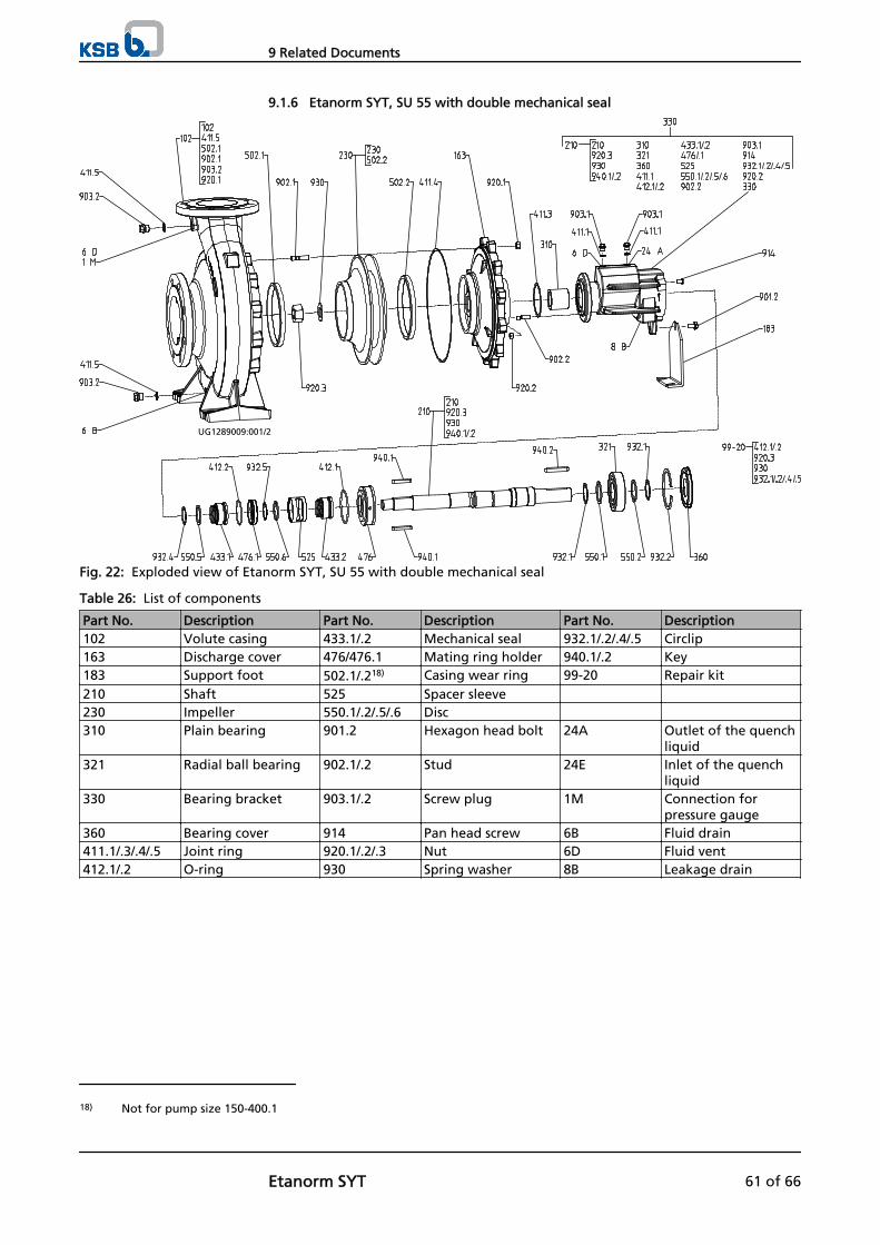
9.1.6 Etanorm SYT, SU 55 with double mechanical seal
UG1289009:001/2
Fig. 22: Exploded view of Etanorm SYT, SU 55 with double mechanical seal
Table 26: List of components
Part No. Description Part No. Description Part No. Description102 Volute casing 433.1/.2 Mechanical seal 932.1/.2/.4/.5 Circlip163 Discharge cover 476/476.1 Mating ring holder 940.1/.2 Key183 Support foot 502.1/.218) Casing wear ring 99-20 Repair kit210 Shaft 525 Spacer sleeve 230 Impeller 550.1/.2/.5/.6 Disc 310 Plain bearing 901.2 Hexagon head bolt 24A Outlet of the quench
liquid321 Radial ball bearing 902.1/.2 Stud 24E Inlet of the quench
liquid330 Bearing bracket 903.1/.2 Screw plug 1M Connection for
pressure gauge360 Bearing cover 914 Pan head screw 6B Fluid drain411.1/.3/.4/.5 Joint ring 920.1/.2/.3 Nut 6D Fluid vent412.1/.2 O-ring 930 Spring washer 8B Leakage drain
18) Not for pump size 150-400.1
9 Related Documents
Etanorm SYT 61 of 66

9.1.7 Etanorm SYT with SiC plain bearing
Fig. 23: Exploded view of Etanorm SYT with plain bearing
Table 27: List of components
Part No. Description Part No. Description Part No. Description381 Bearing cartridge 412.3 O-ring 529 Bearing sleeve540.1 Bush 561 Half round head
grooved pin932.6/.7 Circlip
9.2 Wiring diagrams for double mechanical seal
Fig. 24: Wiring diagram for double mechanical seal
1M.1/.2 Connection for pressure gauge6B Fluid drain6D Fluid vent8B Leakage drain24A Outlet of the quench liquid24E Inlet of the quench liquid
9 Related Documents
62 of 66 Etanorm SYT
10 EC Declaration of Conformity
Manufacturer: KSB AktiengesellschaftJohann-Klein-Straße 9
67227 Frankenthal (Germany)
The manufacturer herewith declares that the product:
Etabloc, Etabloc SYT, Etaline, Etaline SYT, Etaline Z,Etachrom NC, Etachrom BC, Etanorm, Etanorm SYT,
Etanorm GPV/CPV, Etaprime L, Etaprime B/BN, Vitachrom
KSB order number: ...................................................................................................
▪ is in conformity with the provisions of the following Directives as amended from time to time:
– Pump (set): Machinery Directive 2006/42/EC
The manufacturer also declares that
▪ the following harmonised international standards have been applied:
– ISO 12100,
– EN 809/A1
Person authorised to compile the technical file: Name
Function Address (company)Address (Street, No.)Address (post or ZIP code, city)
The EC Declaration of Conformity was issued in/on:
Place, date
..............................19) .............................
Name
FunctionCompanyAddress
Address
19) A signed, legally binding declaration of conformity is supplied with the product.
10 EC Declaration of Conformity
Etanorm SYT 63 of 66

11 Certificate of Decontamination
Type ................................................................................................................................Order number/Order item number20) ................................................................................................................................ Delivery date ................................................................................................................................ Field of application: ................................................................................................................................ Fluid handled20) : ................................................................................................................................
Please tick where applicable20) :
⃞ ⃞ ⃞ ⃞radioactive explosive corrosive toxic
⃞ ⃞ ⃞ ⃞harmful bio-hazardous highly flammable safe
Reason for return20) : ................................................................................................................................ Comments: ................................................................................................................................ ................................................................................................................................ The product/accessories have been carefully drained, cleaned and decontaminated inside and outside prior to dispatch/placing at your disposal.
On seal-less pumps, the rotor has been removed from the pump for cleaning.
⃞ No special safety precautions are required for further handling.⃞ The following safety precautions are required for flushing fluids, fluid residues and disposal:
............................................................................................................................................................... ............................................................................................................................................................... We confirm that the above data and information are correct and complete and that dispatch is effected in accordance withthe relevant legal provisions.
.................................................................... ....................................................... .......................................................Place, date and signature Address Company stamp
20) Required fields
11 Certificate of Decontamination
64 of 66 Etanorm SYT

Index
AAbrasive fluids 36
BBearing temperature 39Bearings 17
CCertificate of Decontamination 64Clearances 40Commissioning/start-up 31Coupling 40Coupling alignment 26
DDesign 16, 17Designation 16Direction of rotation 30Dismantling 42Disposal 14
EExplosion protection 10, 19, 20, 26, 28, 29, 31, 32, 34,35, 38, 39, 40, 41
FFilter 22, 41Final check 32Frequency of starts 35Function 17
GGrease lubrication
Intervals 41
IImpeller type 17Installation
Installation on a foundation 20Installation without foundation 21
Installation at site 20Intended use 8Interchangeability of pump components 52
MMechanical seal 33Misuse 9Monitoring equipment 12
NName plate 16Noise characteristics 18
OOperating limits 8, 34Order number 6Ordering spare parts 50Other applicable documents 6
PPartly completed machinery 6Permissible forces at the pump nozzles 24Piping 22Preservation 14, 36Priming and venting 31Pump casing 16
RReassembly 42, 46Return to supplier 14Returning to service 36
SSafety 8Safety awareness 9Scope of supply 19Servicing/maintenance 38Shaft seal 17Shutdown 36Spare parts stock 50Start-up 33Storage 14, 36
TTemperature limits 11Tightening torques 49Transport 13Trouble-shooting 54
Index
Etanorm SYT 65 of 66

KSB Aktiengesellschaft67225 Frankenthal • Johann-Klein-Str. 9 • 67227 Frankenthal (Germany)Tel. +49 6233 86-0 • Fax +49 6233 86-3401www.ksb.com
1226
.8/2
-EN