Project Manual for SITE PREPARATION,...
306
Project Manual for SITE PREPARATION, PLACEMENT, AND INSTALLATION OF MODULAR BUILDINGS At LUSHER CHARTER SCHOOL 5624 FRERET STREET In New Orleans, Louisiana 70115 “Project # 2011-0863-0002” Orleans Parish School Board Prepared by: Orleans Parish School Board Facilities and Purchasing Departments “April 3, 2014” Project no. 2011-0863-0002, Site Preparation, Placement, and Installation of Modular Buildings at Lusher-Fortier Page 1 of 306
-
Upload
duongtuong -
Category
Documents
-
view
215 -
download
2
Transcript of Project Manual for SITE PREPARATION,...
Project Manual
for
SITE PREPARATION, PLACEMENT, AND INSTALLATION OF MODULAR BUILDINGS
At
LUSHER CHARTER SCHOOL 5624 FRERET STREET
In
New Orleans, Louisiana 70115
“Project # 2011-0863-0002”
Orleans Parish School Board
Prepared by:
Orleans Parish School Board Facilities and Purchasing Departments
“April 3, 2014”
Project no. 2011-0863-0002, Site Preparation, Placement, and Installation of Modular Buildings at Lusher-Fortier
Page 1 of 306

ORLEANS PARISH SCHOOL BOARD PURCHASING/ANCILLARY SERVICES DEPARTMENT
3520 General De Gaulle Drive, 5th Floor, Room 5078 New Orleans, Louisiana 70114
ADVERTISEMENT
PROJECT NO. 2011-0863-0002
SITE PREPARATION, PLACEMENT, AND INSTALLATION
OF MODULAR BUILDINGS AT THE LUSHER-FORTIER SITE
Sealed bids relative to the above will be received in the Purchasing Department for the Orleans Parish School Board (OPSB), 3520 General DeGaulle Drive, Room 5078, New Orleans, Louisiana 70114 until 2:00 PM on Monday, May 5, 2014. A mandatory pre-bid conference and walk-through will be held at Lusher Charter Middle and High School, 5624 Freret Street, New Orleans, LA 70115 at 10:00 A.M. on Monday, April 21, 2014 to address any questions or concerns relative to the invitation to bid. All Bidders (or their authorized representatives) are required to attend. An addendum may be issued in response to questions raised at the walk-through. Specifications and bidding documents may be obtained upon request from the OPSB Purchasing Department in writing, by email ([email protected]), by calling (504) 304-5645 or by visiting the web site www.opsb.us/solicitations. The OPSB reserves the right to reject any or all proposals whenever such rejection is in its best interest in accordance with law. The provisions and requirements of this advertisement shall not be waived.
ORLEANS PARISH SCHOOL BOARD BY: Mr. Leslie J. Rey
Purchasing/Ancillary Services Director FIRST INSERTION DATE: FRIDAY, APRIL 4, 2014 SECOND INSERTION DATE: FRIDAY, APRIL 11, 2014 THIRD INSERTION: FRIDAY, APRIL 18, 2014
Project no. 2011-0863-0002, Site Preparation, Placement, and Installation of Modular Buildings at Lusher-Fortier
Page 2 of 306

INSTRUCTIONS TO BIDDERS
1. The Orleans Parish School Board (OPSB) is soliciting sealed bids to furnish all materials, labor, insurance, permits, supervision and equipment to perform the site preparation, placement, and installation of modular buildings according to the specifications per the scope of work outlined in the general conditions. See attached technical specifications. The job site is located at Lusher Charter School, 5624 Freret Street, New Orleans, Louisiana 70115. Sealed bids will be received by the Office of Purchasing/Ancillary Services, Room 5078, 3520 General De Gaulle Drive, New Orleans, Louisiana 70114, until 2:00 P.M. CST on Monday, May 5, 2014. Bids are to be submitted using the Louisiana Uniform Public Works Bid Form Only. Any interlineation, alteration, modification, erasure or change of any kind on the Bid Form must be initialed by the signer of the bid. You must include your Louisiana State General Contractor’s license number where indicated on the Bid Form. Bids are to be submitted in a sealed envelope with the project name and project/bid number on the outside of the envelope, along with your Louisiana State General Contractor’s license number. All bids shall be valid for a minimum of 120 days. Payment terms shall be net 30 days.
2. A mandatory pre-bid conference and walk-through will be held at Lusher Charter High School, 5624 Freret Street on Monday, April 21, 2014 at 10:00 A.M. CST. In the event Bidders combine with other Bidders to form Joint Ventures to Bid on this Project, a representative of each member of the Joint Venture must attend the Pre-Bid Conference. Any revision of the Bidding Documents made as a result of the Pre Bid Conference shall be documented in an Addendum to the Contract Documents, and shall not be valid unless included in an Addendum.
3. Bidders must check their bid for mathematical and typographical errors before submittal. All corrections must be initialed. Failure to comply may result in disqualification of bid.
4. Bid Security 4.1 No Bid shall be considered or accepted unless the Bid is accompanied by bid security in an amount of not less than five percent (5%) of the Base Bid plus all Alternates.
The bid security shall be in the form of a certified check or cashier's check drawn on a bank
insured by the Federal Deposit Insurance Corporation, or a Bid Bond written by a surety company licensed to do business in Louisiana and signed by the surety's agent or attorney in fact. The Bid Bond shall be written on the Orleans Parish School Board Bid Bond Form (furnished with the Bidding Documents), and the surety for the bond must meet the qualifications stated thereon. The Bid Bond shall be in favor of the Orleans Parish School Board, and shall be accompanied by appropriate power of attorney. The Bid Bond must be signed by both the Bidder/principal and the surety in the space provided on the Orleans Parish School Board Bid Bond Form. Failure by the Bidder/principal or the surety to sign the bid bond shall result in the rejection of the bid.
Bid security furnished by the Contractor shall guarantee that the Contractor will, if awarded
the Contract according to the terms of his Bid, enter into the Agreement with the Owner for the Work, and that Contractor shall execute such Agreement and all other Contract Documents requiring execution within ten (10) days after written notice that the instrument is ready for his signature. Bid Security furnished by the Contractor shall further guarantee that Contractor will furnish Performance and Payment Bonds as required by these Instructions and the Contract Documents. Should the Bidder fail or refuse to enter into such Agreement or fail or refuse to furnish said Performance or Payment Bonds, the amount of the bid security shall be forfeited to the Owner as liquidated damages, which shall not be considered a penalty.
Project no. 2011-0863-0002, Site Preparation, Placement, and Installation of Modular Buildings at Lusher-Fortier
Page 3 of 306

4.2 The Owner will have the right to retain the bid security of Bidders until the later of: (a) the Agreement with the Owner and all other Contract Documents requiring execution have been executed and Performance and Payment Bonds have been furnished; or (b) the specified time provided in the law and/or the Bidding Documents has elapsed so that bids may be withdrawn; or (c) all bids have been rejected.
5. Rejection of Bids 5.1 The Owner shall have the right to reject any or all bids for just cause. The Owner shall reject any Bids not accompanied by the required bid security. The Owner shall reject any Bids not accompanied by any data or other documents required by the Bidding Documents, or that are incomplete or irregular in any way. The Owner shall reject any Bids that are nonresponsive to the requirements of the Bidding Documents. 5.2 The Owner shall have the right to disqualify any Bidder who is determined to be not responsible, as provided in La. R.S. 38:2212.J. 5.3 In accordance with the provisions of R.S. 39:2182, in awarding contracts after August 15, 2010, any public entity is authorized to reject a proposal or bid from, or not award the contract to, a business in which any individual with an ownership interest of five percent or more, has been convicted of, or has entered a plea of guilty or nolo contendere to any State felony crime or equivalent federal felony crime committed in the solicitation or execution of a contract or bid awarded under Laws governing public contracts under the provisions of Chapter 10 of Title 38 of the Louisiana Revised Statutes of 1950, professional, personal, consulting, and social services procurement under the provisions of Chapter 16 of this Title, or the Louisiana Procurement Code under the provisions of chapter 17 of this title. In accordance with the provisions of R.S. 38:2212.8, in awarding contracts after August 15, 2010, any public entity is authorized to reject the lowest bid from, or not award the contract to, a business in which any individual with an ownership interest of five percent or more has been convicted of, or has entered a plea of guilty or nolo contendere to any state felony crime or equivalent federal felony crime committed in the solicitation or execution of a contract or bid awarded under the laws governing public contracts under the provisions of Chapter 10 of this Title, professional, personal, consulting, and social services procurement under the provisions of Chapter 16 of Title 39 of the Louisiana Revised Statutes of 1950, or the Louisiana Procurement Code under the provisions of Chapter 17 of Title 39 of the Louisiana Revised Statutes of 1950. 5.4 In accordance with Louisiana Law (La. R.S. 38:2227 and LA. R.S. 38:2212.10), each bidder on this project shall submit the completed Attestation Clause (Past Criminal Convictions of Bidders and Verification of Employees) form, a copy of which is included in the Bidding Documents, to the Orleans Parish School Board, Office of Purchasing/Ancillary Services. The Attestation Clause form is NOT REQUIRED to be included with the bid form. The Attestation Clause form shall be RECEIVED by the Orleans Parish School Board, Office of Purchasing/Ancillary Services no later than 4:00 p.m. on the tenth day following the bid opening. The submission should be identified with the name of the bidder, the project on which he is bidding, and the words ATTESTATION CLAUSE. Forms may be sent via US Mail, express mail, or hand delivered to:
Project no. 2011-0863-0002, Site Preparation, Placement, and Installation of Modular Buildings at Lusher-Fortier
Page 4 of 306
Mr. Leslie J. Rey Orleans Parish School Board
Office of Purchasing / Ancillary Services 3520 General De Gaulle Drive
Suite 5078 New Orleans, LA 70114
5.5 The apparent lowest offeror/bidder shall complete and submit the “DBE Form 1 – DBE Responsiveness Form” and any other documents required according to the response within ten (10) days after the opening of the Bids to the Orleans Parish School Board, Office of Purchasing/Ancillary Services with a copy to the Disadvantaged Business Enterprise (DBE) Office. The DBE Form 1 is NOT REQUIRED to be included with the bid form. The DBE Form 1 shall be RECEIVED by the Orleans Parish School Board, Office of Purchasing/Ancillary Services and the DBE Office no later than 4:00 p.m. on the tenth day following the bid opening. The submission should be identified with the name of the bidder, the project on which he is bidding, and the words DBE Documents. Documents may be sent via US Mail, express mail, or hand delivered to: Mr. Leslie J. Rey Orleans Parish School Board Office of Purchasing / Ancillary Services 3520 General De Gaulle Drive Suite 5078 New Orleans, LA 70114
Mr. Armer Bright Executive Director Disadvantaged Business Enterprise Orleans Parish School Board 3520 General DeGaulle Drive Suite 5055 New Orleans, LA 70114
6. Time of Delivery and Form of Bonds
6.1 The Bidder shall deliver the required bonds to the Owner simultaneous with the execution of the Contract. 6.2 Bonds shall be written on the AIA Forms, as revised by the Owner, furnished by the Orleans Parish School Board, entitled PERFORMANCE BOND and PAYMENT BOND, copies of which are included in the Bidding Documents. 6.3 The Bidder shall require the Attorney in Fact who executes the required bonds on behalf of the Surety to affix thereto a certified and current copy of his power of Attorney. 6.4 If at any time a Surety on any such Bond is declared bankrupt or loses its right to do business in the State in which the Work is to be performed or is removed from the list of Surety companies accepted on Federal Bonds, the Contractor shall, within two (2) calendar days of becoming aware of same, notify the Owner of such event, and within five (5) calendar days of becoming aware of same, substitute an acceptable Bond in such form and sum and signed by such other Surety or Sureties as may be satisfactory to the Owner. The premiums of such Bond shall be paid by the Contractor. No further payment by the Owner to the Contractor shall be deemed due nor shall be made until the new Surety or Sureties shall have furnished an acceptable Bond to the Owner. 6.5 Every Bond under this Paragraph must display the Surety’s Bond Number. A rider including the following provisions shall be attached to each Bond.
Project no. 2011-0863-0002, Site Preparation, Placement, and Installation of Modular Buildings at Lusher-Fortier
Page 5 of 306
6.5.1 Surety hereby agrees that it consents to and waives notice of any addition, alteration, omission, change, or other modification of the Contract Documents, other than any change in Work which exceeds twenty (20%) percent of the Contract Sum. Any addition, alteration, change, extension of time, or other modification of the Contract Documents, or a forbearance on the part of either the Owner or the Contractor to the other, shall not release the Surety of its obligations hereunder and notice to the surety of such matters is hereby waived. 6.5.2 Surety further agrees that in the event of any default by the Owner in the performance of the Owner’s obligations to the Contractor under the Contract, the Contractor or Surety shall cause written notice of such default (specifying said default in detail) to be given to the Owner, and the Owner shall have thirty (30) days from time after receipt of such notice within which to cure such default. Such notice of default shall be sent by certified or registered U.S. Mail, return receipt requested, first class postage prepaid, to the Owner. 6.5.3 Surety agrees that it is obligated under the bonds to any successor, grantee, or assignee of the Owner as their interests may be given. 6.5.4 Surety agrees that it is obligated under the bond for payment of any liquidated damages owed to the Owner by Contractor.
6.6 The Surety shall be bound in solido with the Contractor. The executed bonds, together with the bonding agent’s power of attorney, shall be furnished to the Owner along with executed Contract Documents and the number of copies reasonably required by him. The Contractor shall deliver the required bonds to the Owner not later than the date of execution of the Contract Documents. 6.7 Additional performance and payment bonds may be required by the Owner, in the Owner’s sole discretion from any Subcontractor whose Subcontract exceeds ONE HUNDRED THOUSAND ($100,000.00) DOLLARS. The Owner shall pay for any premiums charged for obtaining required Subcontractor bonds by executing a Change Order which shall increase the Contract Sum in an amount equal to such premiums. All such bonds shall be in form and substance satisfactory to the Owner in the Owner’s sole judgment.
7. In accordance with Louisiana Law the successful Bidder shall deliver the fully executed Non Collusion Affidavit, a copy of which is included in the Bidding Documents, simultaneous with the execution of the Contract.
8. The Orleans Parish School Board is exempt from all Federal, State, and Local taxes.
9. The apparent low bidder must furnish their Certificate of Insurance before contract execution, in accordance with the insurance requirements.
10. Legal identification of the company and/or organization must be listed on the bid form where indicated, including its corporate name and complete mailing address.
11. The Orleans Parish School Board reserves the right to select any part of the bid or the entire bid, as well as to reject any and all bids received whenever such selection or rejection is in its best interest in accordance with law.
Project no. 2011-0863-0002, Site Preparation, Placement, and Installation of Modular Buildings at Lusher-Fortier
Page 6 of 306
12. A bid may be withdrawn after the time and date designated for receiving bids if clear and convincing sworn, written evidence of obvious mechanical, clerical or mathematical error is furnished by the bidder within 48 hours of bid opening.
13. Negligence on the part of the bidder in preparing his/her bid confers no right of withdrawal or modification of his/her bid after bids have been opened.
14. All inquiries regarding this solicitation for bids should be in writing and e-mailed to Mr. Leslie Rey, [email protected].
15. All bidders must be licensed as a general contractor with the Louisiana State Licensing Board.
16. The OPSB is seeking a Disadvantaged Business Enterprise (DBE) goal of 32%. See DBE Packet which is hereby made a part of this Invitation to Bid (ITB).
Project no. 2011-0863-0002, Site Preparation, Placement, and Installation of Modular Buildings at Lusher-Fortier
Page 7 of 306

LOUISIANA UNIFORM PUBLIC WORKS BID FORM TO: Orleans Parish School Board BID FOR: Site Preparation, Placement, and Installation of Office of Purchasing/Ancillary Services Modular Buildings at Lusher-Fortier 3520 General DeGaulle Drive, Suite 5078 Lusher Charter School New Orleans, Louisiana 70114 5624 Freret Street New Orleans, Louisiana 70115
The undersigned bidder hereby declares and represents that she/he; a) has carefully examined and understands the Bidding Documents, b) has not received, relied on, or based his bid on any verbal instructions contrary to the Bidding Documents or any addenda, c) has personally inspected and is familiar with the project site, and hereby proposes to provide all labor, materials, tools, appliances and facilities as required to perform, in a workmanlike manner, all work and services for the construction and completion of the referenced project, all in strict accordance with the Bidding Documents prepared by: and dated: _____________ Bidders must acknowledge all addenda. The Bidder acknowledges receipt of the following ADDENDA: (Enter the number the Designer has assigned to each of the addenda that the Bidder is acknowledging) TOTAL BASE BID: For all work required by the Bidding Documents (including any and all unit prices DESIGNATED “Base Bid” * but not alternates) the sum of: Dollars ($ ) ALTERNATES: For any and all work required by the Bidding Documents for Alternates including any and all unit prices designated as alternates in the unit price description. Alternate No. 1 (provide description of alternate and state whether add or deduct,) the lump sum of: NOT APPLICABLE Dollars ($ ) Alternate No. 2 (provide description of alternate and state whether add or deduct) the lump sum of: NOT APPLICABLE Dollars ($ ) Alternate No. 3 (provide description of alternate and state whether add or deduct) the lump sum of: NOT APPLICABLE Dollars ($ ) NAME OF BIDDER:
ADDRESS OF BIDDER:
LOUISIANA CONTRACTOR’S LICENSE NUMBER:
NAME OF AUTHORIZED SIGNATORY OF BIDDER:
TITLE OF AUTHORIZED SIGNATORY OF BIDDER:
SIGNATURE OF AUTHORIZED SIGNATORY OF BIDDER **:
DATE:
Project no. 2011-0863-0002, Site Preparation, Placement, and Installation of Modular Buildings at Lusher-Fortier
Page 8 of 306
INDEMNITY AND INSURANCE
A. The Contractor shall indemnify and hold harmless the OPSB, its Board Members, Officers, Staff Directors, etc. for and against any and all losses, damages, and liabilities whatsoever for injury to or death of persons, or loss of or damage to property, including Government property of any kind or nature caused by or arising out of the performance of the work or services required hereunder by the contractor or the officers, employees, or agents of the Contractor.
B. The Contractor shall, as a minimum, obtain and maintain during the entire period of performance of
this contract insurance provided by insurers authorized to transact business in the State of Louisiana, has and maintains a minimum of an “A” rating or better financial size category as shown in the most current AM Best Company ratings the following coverage placements:
1. Workmen's Compensation and Employees Liability Insurance – Worker’s Compensation
insurance limits as required by the Labor Code of the State of Louisiana meeting minimum statutory requirements and Employer’s Liability coverage with a minimum of $500,000. The policy shall include a waiver of subrogation in favor of the District (OPSB).
2. Comprehensive General Liability/ Professional Liability Insurance – For Standard
Contracts, minimum limits of $1,000,000 per occurrence. The policy shall include a waiver of subrogation in favor of the OPSB with an additional insured endorsement. For Architectural & Engineering (A&E) projects, the Contractor shall provide evidence of coverage for Professional Liability and or E&O Liability subject to limits of not less than $1,000,000 with additional insured and/or a waiver of subrogation endorsement in favor of the District (OPSB). The liability insurance shall remain in effect until the end of the Correction Period and at all times after that when the Contractor may be correcting or removing and replacing, defective work.
3. Motor Vehicle Liability Insurance - Minimum limits of $250,000 per person and $500,000 per
occurrence for bodily injury liability and $100,000 for property damage liability is required on each vehicle owned, non owned or hired to be used in conjunction with the contract. The policy shall include a waiver of subrogation in favor of the District (OPSB).
4. Property, Builder’s Risk Insurance – The Contractor (for repair, construction, fabrication, etc.
projects) shall purchase and maintain property insurance, including earth movement and flood, covering work at the site in the full amount of the respective contract and/or changes in contract values due to change orders. The property insurance shall be “All Risk Builder’s Risk Completed Value Form Insurance” or equivalent manuscript policy and shall include the interests of the OSPB, Contractor, Subcontractors and Suppliers, Architect and the Owners and Architect’s consultants as their interest may appear, all of whom shall be named as additional insured’s. The corresponding deductibles, shall be borne by the Contractor & the policy shall also be endorsed to comply with the waiver of subrogation rights in favor of or applicable to the OPSB.
5. Excess Liability Insurance – The OPSB reserves the right to require this coverage subject to
the value of the contract or scope of work required in the contract. If required, the excess liability insurance shall follow the same form and offer the same protections as employer’s liability, general liability and auto liability. It shall also be as broad as the underlying policies of liability. Limits of Excess Liability coverage will be established based on the size and scope of the contract project. Additional insured and/or waiver of subrogation endorsements will
Project no. 2011-0863-0002, Site Preparation, Placement, and Installation of Modular Buildings at Lusher-Fortier
Page 9 of 306
be required.
C. The minimum insurance amounts specified in paragraph B shall not include a deductible. Notwithstanding, if there is a deductible incorporated into the terms of the insurance policy, then OPSB shall not be liable for the deductible, nor shall it be an allowable cost if paid by the CONTRACTOR. Insurance issued on a claims-made basis and completed operations insurance shall be maintained for 2 years after acceptance and evidence of coverage shall be furnished to the OPSB yearly.
D. The insurer’s cost of providing the insured’s a defense and appeal, including attorney fees, shall be
supplementary and shall not be included as part of the policy limits, but shall remain the insurer’s separate responsibility. If any of the Contractor’s sureties or insurers is declared bankrupt or placed into receivership, ceases to meet any of the requirements of the Contract Documents or its license to do business in the State of Louisiana is revoked or expires, the Contractor shall meet the requirements of the contract documents.
E. Certificates of insurance evidencing that the requirements of paragraph B have been met shall be
submitted with the bid to OPSB. In addition to the certificate of insurance, a copy of all required endorsements will be required as proof of the coverage placement. The insurance required pursuant to the provisions of this clause shall be in such form and for such periods of time as OPSB may require or approve, and with insurers approved by OPSB. Provisions shall be made for 30 days advance written notice by mail to OPSB of change in or cancellation of such insurance.
F. In the event the CONTRACTOR fails to continue to maintain such insurance during the performance
of the Contract OPSB shall have the right to withhold any payments or partial payments required to be made under this Contract; and shall have the right to continue withholding any or all of said payments so long as the CONTRACTOR has not complied with the requirements of this clause.
Project no. 2011-0863-0002, Site Preparation, Placement, and Installation of Modular Buildings at Lusher-Fortier
Page 10 of 306
2010 B 4 - 4
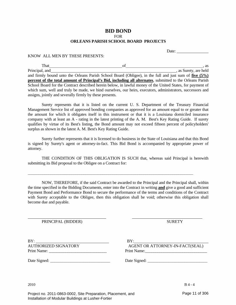
BID BOND FOR ORLEANS PARISH SCHOOL BOARD PROJECTS Date: KNOW ALL MEN BY THESE PRESENTS:
That of , as Principal, and , as Surety, are held and firmly bound unto the Orleans Parish School Board (Obligee), in the full and just sum of five (5%) percent of the total amount of Principal’s Bid, including all alternates, submitted to the Orleans Parish School Board for the Contract described herein below, in lawful money of the United States, for payment of which sum, well and truly be made, we bind ourselves, our heirs, executors, administrators, successors and assigns, jointly and severally firmly by these presents.
Surety represents that it is listed on the current U. S. Department of the Treasury Financial Management Service list of approved bonding companies as approved for an amount equal to or greater that the amount for which it obligates itself in this instrument or that it is a Louisiana domiciled insurance company with at least an A - rating in the latest printing of the A. M. Best's Key Rating Guide. If surety qualifies by virtue of its Best's listing, the Bond amount may not exceed fifteen percent of policyholders' surplus as shown in the latest A. M. Best's Key Rating Guide.
Surety further represents that it is licensed to do business in the State of Louisiana and that this Bond is signed by Surety's agent or attorney-in-fact. This Bid Bond is accompanied by appropriate power of attorney.
THE CONDITION OF THIS OBLIGATION IS SUCH that, whereas said Principal is herewith submitting its Bid proposal to the Obligee on a Contract for: ________________________________________________________________________________
NOW, THEREFORE, if the said Contract be awarded to the Principal and the Principal shall, within
the time specified in the Bidding Documents, enter into the Contract in writing and give a good and sufficient Payment Bond and Performance Bond to secure the performance of the terms and conditions of the Contract with Surety acceptable to the Obligee, then this obligation shall be void; otherwise this obligation shall become due and payable.
PRINCIPAL (BIDDER) SURETY BY: BY: AUTHORIZED SIGNATORY AGENT OR ATTORNEY-IN-FACT(SEAL) Print Name: ____________________________ Print Name:______________________________ Date Signed: _____________________________ Date Signed: _____________________________
Project no. 2011-0863-0002, Site Preparation, Placement, and Installation of Modular Buildings at Lusher-Fortier
Page 11 of 306

2010 C-3-3
STATE OF LOUISIANA PARISH OF PROJECT NO. NAME: LOCATION: AFFIDAVIT
Before me, the undersigned authority, duly commissioned and qualified within and for the State and Parish aforesaid, personally came and appeared (hereinafter “Affiant”), the duly authorized and lawful representative of ____________________, who, being by me first duly sworn deposed, testified under oath that he has read this Affidavit and does hereby agree to comply with all provisions herein , and affirms under oath as follows: PART I
Louisiana Revised Statutes, Title 38, Section 2224:
(1) That Affiant employed no person, corporation, firm, association, or other organization, either directly or indirectly, to secure the public Contract between ____________________ and the Orleans Parish School Board, under which Affiant has or will receive payment, other than persons regularly employed by the Affiant whose services in connection with the construction, alteration or demolition of the public building or project or in securing the public Contract were in the regular course of their duties for Affiant; and
(2) That no part of the Contract price received by Affiant was paid or will be paid to any person, corporation, firm, association, or other organization for soliciting the Contract, other than the payment of their normal compensation to persons regularly employed by the Affiant whose services in connection with the construction, alteration or demolition of the public building or project were in the regular course of their duties for affiant. PART II
Louisiana Revised Statutes, Title 38, Section 2190:
That Affiant, if an architect or engineer, or representative thereof, does not own a substantial financial interest, either directly or indirectly, in any corporation, firm, partnership, or other organization which supplies materials for the construction of a public work when the architect or engineer has performed architectural or engineering services, either directly or indirectly, in connection with the public work for which the materials are being supplied.
For the purposes of this section, a "substantial financial interest" shall exclude any interest in stock being traded on the American Stock Exchange or the New York Stock Exchange.
That Affiant, if subject to the provisions of this section, does hereby agree to be subject to the penalties involved for the violation of this section. _______________________________________ AFFIANT
SWORN TO AND SUBSCRIBED BEFORE ME THIS _______ DAY OF ___________, 20____. ______________________________________
NOTARY
Project no. 2011-0863-0002, Site Preparation, Placement, and Installation of Modular Buildings at Lusher-Fortier
Page 12 of 306
2012.01
___________________________ ____________________________ Name of Project Project No.
ATTESTATIONS
Appearer, as a Bidder on the above-entitled Public Works Project, does hereby attest that:
LA. R.S. 38:2227 PAST CRIMINAL CONVICTIONS OF BIDDERS
A. No sole proprietor or individual partner, incorporator, director, manager, officer, organizer, or member who has a minimum of a ten percent (10%) ownership in the bidding entity named below has been convicted of, or has entered a plea of guilty or nolo contendere to any of the following state crimes or equivalent federal crimes: (a) Public bribery (R.S. 14:118) (c) Extortion (R.S. 14:66)
(b) Corrupt influencing (R.S. 14:120) (d) Money laundering (R.S. 14:230)
B. Within the past five years from the project bid date, no sole proprietor or individual partner, incorporator, director, manager, officer, organizer, or member who has a minimum of a ten percent (10%) ownership in the bidding entity named below has been convicted of, or has entered a plea of guilty or nolo contendere to any of the following state crimes or equivalent federal crimes, during the solicitation or execution of a contract or bid awarded pursuant to the provisions of Chapter 10 of Title 38 of the Louisiana Revised Statutes:
(a) Theft (R.S. 14:67) (b) Identity Theft (R.S. 14:67.16) (c) Theft of a business record (R.S.14:67.20) (d) False accounting (R.S. 14:70) (e) Issuing worthless checks (R.S. 14:71)
(f) Bank fraud (R.S. 14:71.1) (g) Forgery (R.S. 14:72) (h) Contractors; misapplication of payments (R.S. 14:202) (i) Malfeasance in office (R.S. 14:134)
LA. R.S. 38:2212.10 Verification of Employees
A. At the time of bidding, Appearer is registered and participates in a status verification system to verify that all
new hires in the state of Louisiana are legal citizens of the United States or are legal aliens.
B. If awarded the contract, Appearer shall continue, during the term of the contract, to utilize a status verification system to verify the legal status of all new employees in the state of Louisiana.
C. If awarded the contract, Appearer shall require all subcontractors to submit to it a sworn affidavit verifying compliance with Paragraphs (A) and (B) of this Subsection. ____________________________________ ________________________________________________ NAME OF BIDDER NAME OF AUTHORIZED SIGNATORY OF BIDDER
____________________________________ _________________________________________________ DATE TITLE OF AUTHORIZED SIGNATORY OF BIDDER
__________________________________________________________
SIGNATURE OF AUTHORIZED SIGNATORY OF BIDDER
Project no. 2011-0863-0002, Site Preparation, Placement, and Installation of Modular Buildings at Lusher-Fortier
Page 13 of 306
PERFORMANCE BOND FOR PROJECT NO. 2011-0863-0002
BE IT KNOWN, that on this __________ day of the month of _____________, in the year of _______________________________ (20____), before me, ________________________________________, a Notary Public, duly commissioned and qualified, in and for the Parish of Orleans, Louisiana, residing in the Parish of Orleans, and in the presence of the named witnesses and the undersigned, personally came and appeared the “Contractor” _________________________________________, represented by ____________________________________________, its ______________________________________, as Principal, and "the Surety," ______________________________________________, of the State of ___________________________________, as Surety, represented by _______________________________________, its ____________________________________________, who severally and mutually guarantee to the Orleans Parish School Board, "the Owner," as obligee, the faithful performance of "the Contract" the Contractor has entered with the Owner for _____________________________________________________, "the Work," covered by the Contract Documents to which this Performance Bond is attached by this reference, and do hereby bind the Contractor and Surety, its successors, legal representatives and assigns, in favor of the Owner, in the full and true sum of __________________________________________________________________________ Dollars ($___________________), payable on demand to the Orleans Parish School Board, in compliance with LSA-R.S. Title 38, Chapter 10.
NOW, THE CONDITION OF THIS OBLIGATION IS AS FOLLOWS. If the Contractor (a) faithfully performs and fulfills all the undertakings, terms, conditions, warranties, indemnifications and agreements of the Contract Documents within the Contract Time (including any authorized changes, with or without notice to the Surety) and during the Correction Period; (b) performs and fulfills all the undertakings, terms, conditions, warranties, indemnifications and agreements of any and all duly authorized modifications of the Contract Documents, notice of which modifications the Surety hereby expressly waives; (c) fully secures and protects the Owner, its legal successor and representative, from all liability in the premises, and from all loss or expense of any kind, including all costs of court and attorney's fees made necessary or arising from the failure, refusal or neglect of the Contractor, to comply with the obligations assumed by Contractor; and (d) delivers all the Work to the Owner free from all claims, liens and expenses; then this obligation shall become null and void, otherwise, THIS OBLIGATION SHALL REMAIN IN FULL FORCE AND EFFECT.
A. Article 14 of Section 00700 General Conditions governing termination shall be binding on the Surety and Contractor.
B. This Section 00610 Performance Bond shall be solely for the protection of the Owner and its successors, legal representatives or assigns. The prevailing party in a suit on this Bond is entitled to recover as part of that party's judgment reasonable attorneys' fees.
C. No change in Contract Price or Contract Time, addition, deletion or other revision in the requirements of the Contract Documents shall diminish, enlarge, release or otherwise modify the Surety's obligations under this Section 00610 Performance Bond. The Surety hereby waives notice of any such change in Contract Price or Contract Time, addition, deletion or other revision.
D. It is the intention of the Contractor, Surety and Owner that the Surety shall be bound by all terms and conditions of the Contract Documents and the Performance Bond. However, this Performance Bond is executed pursuant to LSA-R.S. 38:2216 and 2219, and if any provision(s) of this Performance Bond is/are illegal, invalid or unenforceable, all other provisions of this Performance Bond shall nevertheless remain in full force and effect, and the Owner shall be protected to the full extent provided by LSA-R.S. Title 38.
IMPORTANT: The Surety shall provide proof satisfactory to the OPSB that the Surety meets the requirements of LSA-R.S. 3822.19. This includes proof that the Surety is currently licensed to do business in Louisiana. Also, that the surety is currently on the U.S. Department of the Treasury Financial Management Service list of approved bonding companies. Or, that the surety is a Louisiana domiciled insurance company with at least an A-rating in the latest printing of the A.M. Best's Key Rating Guide and qualifies under LSA-R.S. 38.2219(A)(1)(a).
Address and Telephone of the Surety Address and telephone of agent licensed and residing in Louisiana
Signed and sealed this ________day of _________________, 20_____.
THE CONTRACTOR (Sign & Print Full Name)
Contractor Name: __________________________________ Print Name: ____________________________________
Witness: _________________________________________ Signature: _____________________________________
Title: _________________________________________
THE SURETY (Sign & Print Full Name)
Agent: ________________________________________
Witness: _________________________________________ Attorney-in-Fact: ________________________________
__________________________________________________ Notary Public
Project no. 2011-0863-0002, Site Preparation, Placement, and Installation of Modular Buildings at Lusher-Fortier
Page 14 of 306

LABOR AND MATERIAL BOND FOR PROJECT NO. 2011-0863-0002
BE IT KNOWN, that on this __________ day of the month of _____________, in the year of ___________________________ (20____), before me, ________________________________________, a Notary Public, duly commissioned and qualified, in and for the Parish of Orleans, Louisiana, residing in the Parish of Orleans, and in the presence of the named witnesses and the undersigned, personally came and appeared the “Contractor” _________________________________________________, represented by ___________________________________________, its ______________________________, as Principal, and "the Surety," ___________________________________________________, of the State of _____________________________________, as Surety, represented by _______________________________________, its _____________________________________________, who severally and mutually guarantee to the Orleans Parish School Board, "the Owner," as obligee, the faithful performance of "the Contract" the Contractor has entered with the Owner for __________________________________________________________, "the Work," covered by the Contract Documents to which this Performance Bond is attached by this reference, and do hereby bind the Contractor and Surety, its successors, legal representatives and assigns, in favor of the Owner, in the full and true sum of ______________________________________________________________________________ Dollars ($____________________), payable on demand to the Orleans Parish School Board, in compliance with LSA-R.S. Title 38, Chapter 10. NOW, THE CONDITION OF THIS OBLIGATION IS AS FOLLOWS. If the Contractor (a) faithfully and promptly pays all Claimants as provided by Law and pays all wages of laborers, workmen, or mechanics, to be employed by any Subcontractor, or by or to Subcontractors, and used in the construction, erection, alteration, installation, or repairs called for by the Contract; (b) promptly pays for all materials or supplies furnished to the Contractor, or by or to any Subcontractor, for use in machines used by the Contractor, or any Subcontractor, in the construction, erection, alteration, installation, or repair of the Work; (c) fully secures and protects the Owner, its legal successor and representative, from all liability in the premises, and from all loss or expense of any kind, including all costs of court and attorney's fees made necessary or arising from the failure, refusal or neglect of the Contractor, to comply with the obligations assumed by Contractor; and (d) delivers all the Work to the Owner free from all claims, liens and expenses, then this obligation shall become null and void, otherwise, THIS OBLIGATION SHALL REMAIN IN FULL FORCE AND EFFECT.
A. No change in Contract Price or Contract Time, addition, deletion or other revision in the requirements of the Contract Documents shall diminish, enlarge, release or otherwise modify the Surety's obligations under this Section 00620 Labor and Materials Payment Bond. The Surety hereby waives notice of any such change in Contract Price or Contract Time, addition, deletion or other revision.
B. It is the intention of the Contractor, Surety and Owner that the Surety shall be bound by all terms and conditions of the Contract Documents and this Labor and Materials Payment Bond. However, this Labor and Materials Payment Bond is executed pursuant to LSA-R.S. Title 38, Chapter 10, Part III and 38:2219, and if any provision(s) of the Bond is/are illegal, invalid or unenforceable, all other provisions of the Bond shall nevertheless remain in full force and effect, and the Owner shall be protected to the full extent provided by LSA-R.S. Title 38. No action under this Labor and Materials Payment Bond may be commenced by any Claimant unless the Claimant asserts a claim and brings action against the Surety or Contractor or both as provided in LSA-R.S. Title 38.
IMPORTANT: The Surety shall provide proof satisfactory to the OPSB that the Surety meets the requirements of LSA-R.S. 3822.19. This includes proof that the Surety is currently licensed to do business in Louisiana. Also, that the surety is currently on the U.S. Department of the Treasury Financial Management Service list of approved bonding companies. Or, that the surety is a Louisiana domiciled insurance company with at least an A-rating in the latest printing of the A.M. Best's Key Rating Guide and qualifies under LSA-R.S. 38.2219(A)(1)(a).
Address and Telephone of the Surety Address and telephone of agent licensed and residing in Louisiana
Signed and sealed this ________day of _________________, 20_____.
THE CONTRACTOR (Sign & Print Full Name)
Contractor Name: __________________________________ Print Name: ____________________________________
Witness: _________________________________________ Signature: _____________________________________
Title: _________________________________________
THE SURETY (Sign & Print Full Name)
Agent: ________________________________________
Witness: _________________________________________ Attorney-in-Fact: ________________________________
__________________________________________________ Notary Public
Project no. 2011-0863-0002, Site Preparation, Placement, and Installation of Modular Buildings at Lusher-Fortier
Page 15 of 306

DBE LANGUAGE ON ALL DBE CONTRACT PROPOSALS:
DISADVANTAGED BUSINESS ENTERPRISE (DBE) PROGRAM
1. DBE Compliance: The Orleans Parish School Board’s DBE Program applies to this contract. It is the policy of the OPSB to practice nondiscrimination based on social and economic disadvantage, race, color, disability, national origin, gender identity, sex, age, disability, marital status, sexual orientation, religion or veteran status. All firms qualifying under this solicitation are encouraged to submit proposals/bids. Award of this contract shall be conditioned upon the apparent lowest bidder satisfying the OPSB DBE Program goal assigned to the particular contract. The offeror/bidder shall agree to use its best efforts, as determined by the DBE Committee in accordance with the factors set forth in the DBE Program to meet the contract goal for DBE participation in the performance of this contract.
2. DBE Participation: The apparent lowest offeror/bidder shall submit the following
information on the DBE Form 1 – DBE Responsiveness Form within ten (10) days after the bid opening. a. The names and addresses of all DBE firms that will participate in the contract; b. The dollar amount commitment of the participation of each DBE firm participating in the
contract, c. Written confirmation from the named DBE(s), verifying their participation in the contract
as provided in the commitments made under (a) and (b) above; and d. If the contract goal is not met, written evidence of best efforts used.
3. Upon receipt of the above-referenced materials, the DBE Committee consisting of the DBE Executive Director, the Purchasing/Ancillary Director and the Head of the Department seeking the Procurement shall then make a recommendation to the Superintendent as to whether the lowest bidder/offeror has agreed to satisfy the DBE contract goal or if not has demonstrated satisfactory good faith efforts to satisfy the DBE contract goal. If it is determined that the lowest bidder/offeror has not agreed to satisfy the DBE contract goal or shown satisfactory good faith effort to do so, the bid shall be rejected as non-responsive to the DBE contract goal, and consideration shall then be given to the next apparent lowest bidder. The procedure set forth in this section shall be repeated with each successive apparent lowest bidder until the lowest bidder satisfying the DBE contract goal or showing satisfactory good faith effort is determined.
Project no. 2011-0863-0002, Site Preparation, Placement, and Installation of Modular Buildings at Lusher-Fortier
Page 16 of 306

Orleans Parish School Board
Disadvantaged Business Enterprise Program
Overview and Administrative Procedures
The Orleans Parish School Board (OPSB) would like to offer firms exciting business opportunities in Professional Services, Construction, and Goods and Services through its Disadvantaged Business Enterprise (DBE) Program. The DBE program’s policy intent is to assist disadvantaged businesses to attain a competitive edge and grow by providing equal access to contracts and procurement opportunities in the OPSB system.
Certification The OPSB is not conducting an independent certification process at this time. To be qualified as a DBE for OPSB contracts, a firm must be certified as a DBE by the Louisiana Unified Certification Program (LUCP) or any of the following five (5) agencies conducting DBE certification within the City of New Orleans. These five (5) are: The City of New Orleans, Sewage and Water Board of New Orleans, New Orleans Aviation Board, Housing Authority of New Orleans, New Orleans Regional Transit Authority (RTA)
Outreach In recruiting potential Economically Disadvantaged Businesses part of our outreach efforts consist of participating in the following trade shows/seminars:
• New Orleans Coalition of Minority Contractors Association Show • Louisiana Association of General Contractor (LAGC) Show • Association of Building Contractors (ABC) Show • Greater New Orleans Coalition of United Contractors (G.N.O.C.U.C.) Show • Engaging all Contractors and Community Organizations with DBE Membership
During these seminars/trade shows we will distribute programmatic literature to hundreds of individuals and interact with them on a one-to-one basis. Additionally, our DBE program will attend all programs sponsored by government and private entities where opportunities to network are maximized including but not limited to:
• U.S. Environmental Protection Agency Small Business Seminars • U.S. Small Business Administration DBE Seminars
Project no. 2011-0863-0002, Site Preparation, Placement, and Installation of Modular Buildings at Lusher-Fortier
Page 17 of 306
• New Orleans Chapter for the National Association of Minority Contractors Other outreach efforts include:
• Conducting monthly vendor assistance meetings for potential clients • Conducting one-on-one vendor assistance meetings for potential clients
Good Faith Efforts
A Bidder’s compliance with the requirement to make Good Faith Efforts to locate and engage the services of DBE businesses in connection with the Project shall be a matter of Bidder responsiveness. The Bidder can demonstrate that it has complied with the requirement by certifying to the DBE Executive Director or his/her designee in writing, that as of the date of the bid submittal:
(i) the Bidder has selected and engaged the services of DBEs, in which case the certification shall include:
(a) the names and addresses of those enterprises engaged by the Bidder
(b) the value of the subcontract and
(c) a description of the work on the Project to be performed by such firm(s) and/or individuals, or
(ii) if despite the Bidder’s Good Faith Efforts, the Bidder was not able to select and engage the services of such enterprises, in which case the Bidder shall include in its written certification the following:
(a) affirmation that, prior to determining that it was unable to locate DBEs, the bidder consulted business registries including those identified by the School District;
(b) affirmation that the bidder attended any pre-bid meeting scheduled to inform DBEs of subcontracting opportunities;
(c) a copy of the written notifications sent to DBEs soliciting their interest in being a subcontractor or supplier on the Project;
(d) the names, addresses, and telephone numbers of DBEs contacted, the date of such contact and the date set for receipt of bids from those businesses;
(e) a copy of the information or a description of the information provided to DBEs regarding the plans and specifications for the work proposed to be subcontracted and how that information could be accessed;
(f) a statement from the Bidder explaining why any DBEs contacted by bidder were not engaged
Project no. 2011-0863-0002, Site Preparation, Placement, and Installation of Modular Buildings at Lusher-Fortier
Page 18 of 306
Upon the Bidders application for waiver of the DBE goals, based on the above circumstances, the DBE Executive Director and Committee shall determine whether or not the bidder satisfied the good faith effort and shall make the appropriate recommendation.
Upon written request of the DBE Executive Director, the bidder will attend a meeting of the Orleans Parish School Board to discuss the specific measures the Bidder has utilized in undertaking the Bidder’s Good Faith Efforts.
Calculations
1. DBE participation will be counted toward meeting the goals as follows:
a. The total dollar value of a direct contract or subcontract or indirect subcontract awarded to a certified DBE will be counted toward the applicable goal.
b. In the case of a joint venture, the portion of the total dollar value of the contract equal to the percentage of the ownership and control of the DBE in the joint venture will be counted toward the applicable goal.
c. Only DBEs that perform a commercially useful function in the work of a contract or subcontract or indirect subcontract will be counted toward the DBE goals. A DBE is considered to perform a commercially useful function when it is responsible for execution of a distinct element of work of a contract or subcontract and carries out its responsibilities by performing, managing, and supervising the work involved. If a DBE contractor subcontracts a significantly greater portion of the work of the contract than would be expected on the basis of normal industry practices, the DBE is presumed not to be performing a commercially useful function. The DBE may present evidence to rebut this presumption.
d. The total dollar value of materials and supplies obtained from DBE suppliers and manufacturers will be counted toward DBE goals if the DBE assumes the actual and contractual responsibility for the provision of the materials and supplies.
e. OPSB through the DBE Executive Director will review the contractor’s DBE involvement efforts throughout contract performance. Such review will include but will not be limited to, the contractor’s and the DBE’s quarterly statements of income from the District which shall document the portion of said income paid to DBE. The Contractor agrees to supply copies of any documentation the District requires in order to complete such a review.
Project no. 2011-0863-0002, Site Preparation, Placement, and Installation of Modular Buildings at Lusher-Fortier
Page 19 of 306

Procurement Management As a result of our procurement management process, several activities are conducted on a monthly basis:
• Reviewing other DBE agency's certified listings, matching their capabilities to upcoming contracts and encouraging these DBE businesses to seek recertification to update their certification status in order to be eligible for the Orleans Parish School Board DBE participation. • Advise certified DBE vendors about bidding opportunities by submittal of written correspondence to these businesses • Providing program information on the Orleans Parish School Board's website and other compliance enforcement forms for the vendors. • Attend and participate in the Staff Contract Review Committee meetings
Staff Contract Review Committee (services)
The purpose of the Staff Contract Review Committee (SCRC) is to review all contracts involving goods/services and professional services and make recommendations on a suitable percentage and feasible areas of DBE participation. The SCRC consists of the DBE Executive Director (who facilitates the meeting), Executive Director of Operations/Facilities, Purchasing/Ancillary Services Director. At the Staff Contract Review Committee meeting the operations department head or representative and/or consultant makes a presentation on each contract brought before the SCRC being considered for public bid. Details provided include the project cost, subcontract areas, percentage of associated cost of each subcontract area recommended for participation and the recommended goal.
DBE Committee The DBE Committee is responsible for setting the DBE participation goal for each project. The specific goal will be set on a project by project basis. Upon receipt of all information relative to and closing of the bid process the DBE Committee consisting of the DBE Executive Director, the Purchasing/Ancillary Services Director and the Head of the Department seeking the Procurement and in the case of Capital Projects the Executive Director of Operations shall then make a recommendation to the Superintendent as to whether the lowest bidder/respondent has agreed to satisfy the DBE contract goal or if not has demonstrated satisfactory good faith efforts to satisfy the DBE contract goal. In determining the percentage of participation by certified DBEs the DBE Committee shall consider the following:
• The type or nature of the work required under the contract • The estimated dollar amount of the contract • The availability of subcontractors for the particular project
Project no. 2011-0863-0002, Site Preparation, Placement, and Installation of Modular Buildings at Lusher-Fortier
Page 20 of 306
• Whether the items of work have been broken down to the smallest reasonable components to facilitate DBE participation goal up to 35% (Thirty Five Percent) pursuant to the Board’s policy .(the goal will be set on a project by project basis)
Involvement in Bid Process The DBE Program is responsible for the following bid process:
• Consult with Project Engineer or departmental representative on each contract to ensure that every item of work has been broken down to the smallest reasonable components to facilitate DBE participation. • Attend pre-bid conferences and offer instruction, and clarification on DBE bid specifications procurement policy, and procedures for sub-contracting. • Answer questions posed by prime contractors at pre-bid conferences relative to DBE issues. • Provide written responses to detailed questions posed by prime contractors on DBE issues. • Consult with Legal Department before releasing responses, as they may have legal considerations • Review bid specifications for consistency with goals established by Staff Contract Review Committee. • Review participation summary sheets to determine if the percentage and DBE dollar amount of subcontract work reported is consistent with established goals. • Review DBE vendor listing to determine if DBE firm listed on participation summary sheet is certified to perform required work. • Review affidavit and supporting documents for consistency in instances when DBE goals are not met, and "good faith effort" is submitted. • Verify DBEs submitted responses which indicate that they were not interested in pursuing work with prime contractors. • Review quality of good faith effort, analyze and make an assessment on same (i.e. whether the prime contractor attended pre-bid meetings, advertised in a general circulation and trade association publications concerning DBE opportunities and allowed them reasonable time to respond, provided written response to a reasonable number of DBE firms and allowed them to participate effectively, followed up initial solicitation of interest by contacting DBEs to determine for sure if they were interested in bidding specific portions of the work was selected to be performed by DBEs to increase likelihood of meeting DBE goals, provided interested DBEs with adequate information about the plans, specifications and requirements of the contract, negotiated in "good faith" with interested DBEs and did not reject them as unqualified without sound reasons based on a thorough investigation of their capabilities, stated in writing reason for rejecting DBEs as unqualified, used the services of available community organizations, small
Project no. 2011-0863-0002, Site Preparation, Placement, and Installation of Modular Buildings at Lusher-Fortier
Page 21 of 306

and/or disadvantaged business groups, local state and federal small or disadvantaged business assistance offices, and other organizations that provide assistance in the recruitment and placement of DBE firms, and made sufficient efforts to negotiate with DBEs for specific sub-bids). • Make presentations to appropriate committees and full Board on bid disputes and other DBE participation concerns. • Provide signed affidavits to Legal Department in instances where litigation is required in bid disputes. • Participate as witnesses in depositions and court cases involving bid disputes.
Monitoring
After contracts are awarded and work has begun the DBE Office through the Executive Director monitors actual utilization of DBEs. This process is carried out by utilizing the following:
• Review Board Reports for approved names of prime contractors, DBE subcontractors percentage of participation and areas of work to be performed • Advise prime contractors in writing through the appropriate forms provided that the percentage and dollar amount of work to be performed on each contract, that any changes in DBE subcontractors will require prior DBE Office approval .and that quarterly report forms on the status of contract expenditures will be submitted • Advise DBE subcontractors in writing as to which prime contractor will be utilizing that firm, the dollar amount of participation, percentage of participation and notification that any changes in acceptances of the subcontract should be reported immediately to the DBE office • Advise prime contractors of the need to complete quarterly compliance report two (2) weeks before due date • Attend construction progress meetings • Review quarterly compliance reports for instances of non-compliance • Conduct site visit to job sites (i.e. conduct visual inspection of labels on trucks and equipment, determine how many workers are present, determine nature of work being performed) • Interview DBE foreman (i.e. clarify what work is being performed, inquire how often prime contractor visits job site, inquire to determine if there are any problems which need to be addressed) • Make follow-up phone calls to prime contractors to determine why participation is not in compliance • Schedule meetings with both prime contractors and DBE subcontractors in instances of non-compliance or where problems are evident
Project no. 2011-0863-0002, Site Preparation, Placement, and Installation of Modular Buildings at Lusher-Fortier
Page 22 of 306

• Send follow up correspondence detailing non-compliance and penalties for same • Take required action in instances of fronting and non-compliance
Project no. 2011-0863-0002, Site Preparation, Placement, and Installation of Modular Buildings at Lusher-Fortier
Page 23 of 306
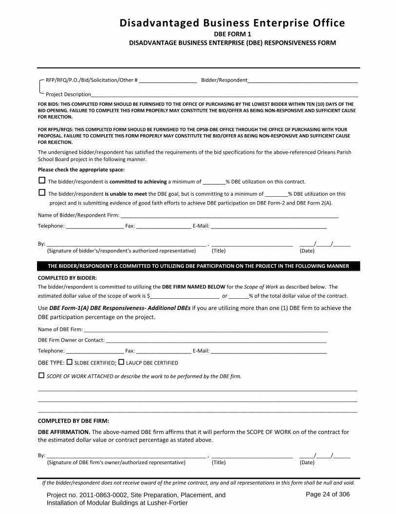
RFP/RFQ/P.O./Bid/Solicitation/Other # ____________________ Bidder/Respondent______________________________________ Project Description____________________________________________________________________________________________
FOR BIDS: THIS COMPLETED FORM SHOULD BE FURNISHED TO THE OFFICE OF PURCHASING BY THE LOWEST BIDDER WITHIN TEN (10) DAYS OF THE BID OPENING. FAILURE TO COMPLETE THIS FORM PROPERLY MAY CONSTITUTE THE BID/OFFER AS BEING NON-RESPONSIVE AND SUFFICIENT CAUSE FOR REJECTION. FOR RFPS/RFQS: THIS COMPLETED FORM SHOULD BE FURNISHED TO THE OPSB-DBE OFFICE THROUGH THE OFFICE OF PURCHASING WITH YOUR PROPOSAL. FAILURE TO COMPLETE THIS FORM PROPERLY MAY CONSTITUTE THE BID/OFFER AS BEING NON-RESPONSIVE AND SUFFICIENT CAUSE FOR REJECTION.
The undersigned bidder/respondent has satisfied the requirements of the bid specifications for the above-referenced Orleans Parish School Board project in the following manner.
Please check the appropriate space:
The bidder/respondent is committed to achieving a minimum of ________% DBE utilization on this contract.
The bidder/respondent is unable to meet the DBE goal, but is committing to a minimum of ________% DBE utilization on this project and is submitting evidence of good faith efforts to achieve DBE participation on DBE Form-2 and DBE Form 2(A).
Name of Bidder/Respondent Firm: ___________________________________________________________________________
Telephone: ____________________ Fax: ___________________ E-Mail: ________________________________________
By: _______________________________________________________ , ____________________________ _____/_____/______ (Signature of bidder's/respondent's authorized representative) (Title) (Date)
THE BIDDER/RESPONDENT IS COMMITTED TO UTILIZING DBE PARTICIPATION ON THE PROJECT IN THE FOLLOWING MANNER
COMPLETED BY BIDDER: The bidder/respondent is committed to utilizing the DBE FIRM NAMED BELOW for the Scope of Work as described below. The estimated dollar value of the scope of work is $________________________ or _______% of the total dollar value of the contract.
Use DBE Form-1(A) DBE Responsiveness- Additional DBEs if you are utilizing more than one (1) DBE firm to achieve the DBE participation percentage on the project.
Name of DBE Firm: ____________________________________________________________________________________
DBE Firm Owner or Contact: ____________________________________________________________________________
Telephone: ____________________ Fax: ___________________ E-Mail: ________________________________________
DBE TYPE: SLDBE CERTIFIED; LAUCP DBE CERTIFIED
SCOPE OF WORK ATTACHED or describe the work to be performed by the DBE firm.
______________________________________________________________________________________________________________
______________________________________________________________________________________________________________
______________________________________________________________________________________________________________
COMPLETED BY DBE FIRM:
DBE AFFIRMATION. The above-named DBE firm affirms that it will perform the SCOPE OF WORK on of the contract for the estimated dollar value or contract percentage as stated above. By: _______________________________________________________ , ____________________________ _____/_____/______ (Signature of DBE firm's owner/authorized representative) (Title) (Date)
If the bidder/respondent does not receive award of the prime contract, any and all representations in this form shall be null and void.
Disadvantaged Business Enterprise Office DBE FORM 1
DISADVANTAGE BUSINESS ENTERPRISE (DBE) RESPONSIVENESS FORM
Project no. 2011-0863-0002, Site Preparation, Placement, and Installation of Modular Buildings at Lusher-Fortier
Page 24 of 306
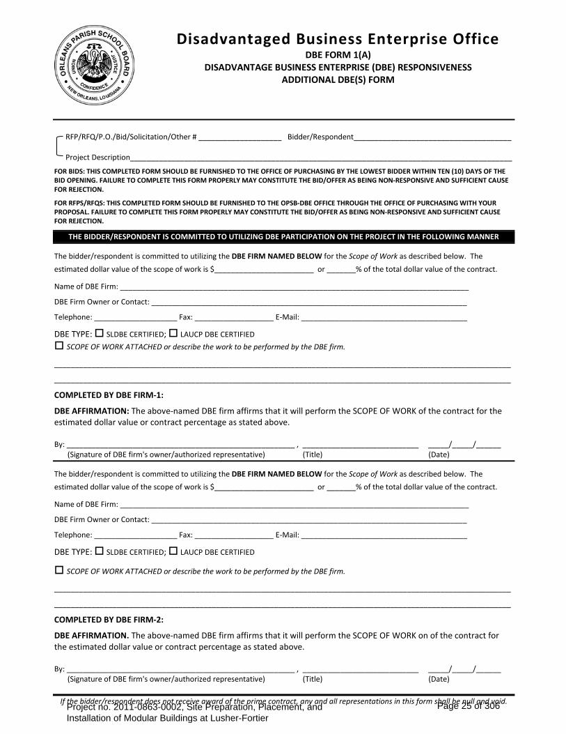
RFP/RFQ/P.O./Bid/Solicitation/Other # ____________________ Bidder/Respondent______________________________________ Project Description____________________________________________________________________________________________
FOR BIDS: THIS COMPLETED FORM SHOULD BE FURNISHED TO THE OFFICE OF PURCHASING BY THE LOWEST BIDDER WITHIN TEN (10) DAYS OF THE BID OPENING. FAILURE TO COMPLETE THIS FORM PROPERLY MAY CONSTITUTE THE BID/OFFER AS BEING NON-RESPONSIVE AND SUFFICIENT CAUSE FOR REJECTION.
FOR RFPS/RFQS: THIS COMPLETED FORM SHOULD BE FURNISHED TO THE OPSB-DBE OFFICE THROUGH THE OFFICE OF PURCHASING WITH YOUR PROPOSAL. FAILURE TO COMPLETE THIS FORM PROPERLY MAY CONSTITUTE THE BID/OFFER AS BEING NON-RESPONSIVE AND SUFFICIENT CAUSE FOR REJECTION.
THE BIDDER/RESPONDENT IS COMMITTED TO UTILIZING DBE PARTICIPATION ON THE PROJECT IN THE FOLLOWING MANNER
The bidder/respondent is committed to utilizing the DBE FIRM NAMED BELOW for the Scope of Work as described below. The estimated dollar value of the scope of work is $________________________ or _______% of the total dollar value of the contract.
Name of DBE Firm: ____________________________________________________________________________________
DBE Firm Owner or Contact: ____________________________________________________________________________
Telephone: ____________________ Fax: ___________________ E-Mail: ________________________________________
DBE TYPE: SLDBE CERTIFIED; LAUCP DBE CERTIFIED
SCOPE OF WORK ATTACHED or describe the work to be performed by the DBE firm.
______________________________________________________________________________________________________________
______________________________________________________________________________________________________________
COMPLETED BY DBE FIRM-1:
DBE AFFIRMATION: The above-named DBE firm affirms that it will perform the SCOPE OF WORK of the contract for the estimated dollar value or contract percentage as stated above. By: _______________________________________________________ , ____________________________ _____/_____/______ (Signature of DBE firm's owner/authorized representative) (Title) (Date)
The bidder/respondent is committed to utilizing the DBE FIRM NAMED BELOW for the Scope of Work as described below. The estimated dollar value of the scope of work is $________________________ or _______% of the total dollar value of the contract.
Name of DBE Firm: ____________________________________________________________________________________
DBE Firm Owner or Contact: ____________________________________________________________________________
Telephone: ____________________ Fax: ___________________ E-Mail: ________________________________________
DBE TYPE: SLDBE CERTIFIED; LAUCP DBE CERTIFIED
SCOPE OF WORK ATTACHED or describe the work to be performed by the DBE firm.
______________________________________________________________________________________________________________
______________________________________________________________________________________________________________
COMPLETED BY DBE FIRM-2:
DBE AFFIRMATION. The above-named DBE firm affirms that it will perform the SCOPE OF WORK on of the contract for the estimated dollar value or contract percentage as stated above. By: _______________________________________________________ , ____________________________ _____/_____/______ (Signature of DBE firm's owner/authorized representative) (Title) (Date)
If the bidder/respondent does not receive award of the prime contract, any and all representations in this form shall be null and void.
Disadvantaged Business Enterprise Office
DBE FORM 1(A) DISADVANTAGE BUSINESS ENTERPRISE (DBE) RESPONSIVENESS
ADDITIONAL DBE(S) FORM
Project no. 2011-0863-0002, Site Preparation, Placement, and Installation of Modular Buildings at Lusher-Fortier
Page 25 of 306

THIS COMPLETED FORM SHOULD BE RETURNED TO THE OPSB-PURCHASING OFFICE BY THE LOWEST APPARENT BIDDER WITHIN TEN (10) DAYS OF THE BID OPENING.
RFP/RFQ/P.O./Bid/Solicitation/Other # ____________________________ Current Date ______/______/_________ Project Description ___________________________________________________________________________________ BIDDER/ OFFERER (FIRM): _____________________________________________________________________________ Contact Person: ________________________________________________ Telephone: ___________________________ Address: ______________________________________________ City: _______________________________________ State ________ Zip _____________ E-Mail: _______________________________________________________
To determine whether a bidder has demonstrated good faith efforts to reach the DBE utilization goal(s) on the above-referenced Orleans Parish School Board (OPSB) project, the DBE Office will consider, at a minimum, EVIDENCE OF GOOD FAITH EFFORTS as described in the table below.
YES () NO () EVIDENCE OF GOOD FAITH EFFORTS PRE-BID MEETING(S): The bidder attended all pre-bid meetings scheduled by the OPSB to inform DBEs of
contracting and subcontracting opportunities. SLDBE/DBE LIST(S): The bidder utilized the OPSB DBE Office’s list or lists of certified SLDBE and/or DBE
firms found on www.nola.gov, www.flymsy.com, www.swbno.org or other state/City DBE lists. SMALL CONTRACT(S): The bidder selected specific portions of the work to be performed by DBEs in order
to increase the likelihood of meeting the DBE goals (including breaking down contracts into smaller units to facilitate DBE participation).
FOLLOW-UP: The bidder followed-up initial indications of interest by DBEs by contacting those DBEs to determine with certainty if they remained interested in bidding by providing proof of same.
ADVERTISEMENT: The bidder advertised in general circulation and/or trade association publications concerning subcontracting opportunities, and allowed DBEs reasonable time to respond.
INTERNET ADVERTISING: The bidder advertised DBE and/or subcontracting opportunities on internet portals that are accessible to DBEs and/or potential subcontractors.
GOOD FAITH NEGOTIATIONS: The bidder negotiated in good faith with interested DBEs and did not reject DBEs as unqualified without sound business reasons based on a thorough investigation of their capabilities.
INFORMATION: The bidder provided interested DBEs with adequate information about the plans, specifications and requirements of the subcontract.
WRITTEN NOTICE(S): The bidder took the necessary steps to provide written notice in a manner reasonably calculated to inform DBEs of subcontracting opportunities and allowed sufficient time for them to participate effectively.
COMMUNITY RESOURCES: The bidder used the services of available community organizations, small and/or disadvantaged business assistance offices and other organizations that provided assistance in the recruitment and placement of DBE firms.
CONTRACT RECORDS: The bidder has maintained the following records for each DBE that has bid on the subcontracting opportunity: 1. Name, address, and telephone number; 2. A description of information provided by the bidder or subcontractor; and 3. A statement of whether an agreement was reached, and if not, why not, including any reasons for concluding that the DBE was unqualified to perform the job.
DISADVANTAGED BUSINESS ENTERPRISE (DBE)
EVIDENCE OF GOOD FAITH EFFORTS OPSB-DBE FORM-2
Project no. 2011-0863-0002, Site Preparation, Placement, and Installation of Modular Buildings at Lusher-Fortier
Page 26 of 306

BACKGROUND
I. POLICY It is the policy of the OPSB to ensure that DBEs, as defined herein, have an equal opportunity to receive and participate in OPSB contracts. It shall also be the policy of the OPSB:
1. To ensure nondiscrimination in the award and administration of OPSB contracts; 2. To create a level-playing field upon which DBEs can compete fairly for OPSB contracts; 3. To ensure that only firms that are DBE certified are permitted to participate as DBEs; 4. To help remove barriers to the participation of DBEs in OPSB contracts; and 5. To assist the development of firms that can compete successfully in the market place outside the DBE Program.
II. DISADVANTAGED BUSINESS ENTERPRISE (DBE) GOALS UP TO THIRTY FIVE PERCENT
The OPSB establishes an overall goal up to 35% utilization of businesses that are socially and economically disadvantaged for all OPSB projects.
III. DEFINITIONS
1. DISADVANTAGED BUSINESS ENTERPRISE Disadvantaged Business Enterprise or "DBE" refers to a firm that is certified through any DBE certification program recognized by OPSB as socially and economically disadvantaged.
2. STANDARDS OF GOOD FAITH EFFORTS The OPSB DBE office through the DBE Committee shall be responsible for determining whether the bidder has made demonstrated Good Faith Efforts to achieve the DBE goal. In order to be considered responsive to any solicitation for any OPSB contract, the bidder must, at a minimum, agree to use its Good Faith Efforts to fully comply with the DBE Program, including all reporting requirements and any specific contract goals for DBE participation. In order for OPSB to evaluate the Good Faith Efforts made by the bidder, the following minimum information is to be provided before the contract is approved for award:
a) A report of all proposals received from a joint venture of DBEs. The report shall indicate the action taken by the bidder in response to the submitted proposals that have been rejected, and the reason for rejection shall be indicated.
b) Documentation of efforts to enter into agreements with DBEs for contracted work and efforts to arrange for a joint
venture, partnership or other multi-entity relationship with DBEs.
c) Documented contact with DBEs, associations, or business development organizations which disseminate information to DBEs.
d) A copy of letters sent to groups in relevant market sectors notifying them of the bidder's intent to submit a proposal
to the OPSB.
e) Description of assistance provided by the bidder to DBEs:
1. Review of Request for Proposal or other documents issued by OPSB.
2. Review of the Scope of Work to be performed.
f) Documentation of any other effort(s) undertaken by the bidder to encourage the participation of DBEs.
Project no. 2011-0863-0002, Site Preparation, Placement, and Installation of Modular Buildings at Lusher-Fortier
Page 27 of 306

g) Overall operation of the bidder may be considered in evaluating the Evidence of Good Faith Efforts of the bidder to comply with the goals and intent of the disadvantaged business enterprise goals for the OPSB.
h) Any other documentation to demonstrate Evidence of Good Faith Efforts to satisfy the objectives outlined above.
IV. ASSISTANCE
You may contact the Orleans Parish School Board’s Disadvantaged Business Enterprise office for assistance with completing this or any other DBE form or document. All prime contractors are encouraged to use the following DBE lists: City of New Orleans, Sewage and Water Board of New Orleans, New Orleans Armstrong International Airport, Housing Authority of New Orleans, New Orleans Regional Transit Authority (RTA) and the State Department of Transportation (DOTD) DBE central registry list. You may also contact the OPSB DBE office for assistance in identifying available, capable, and approved DBE firms.
V. CONTACT US
Orleans Parish School Board DBE Office Disadvantaged Business Enterprise Program
3520 General DeGaulle Drive, Suite 5055 New Orleans, LA 70114 (504) 304-5584 Office
(504) 390-7963 Mobile
Project no. 2011-0863-0002, Site Preparation, Placement, and Installation of Modular Buildings at Lusher-Fortier
Page 28 of 306
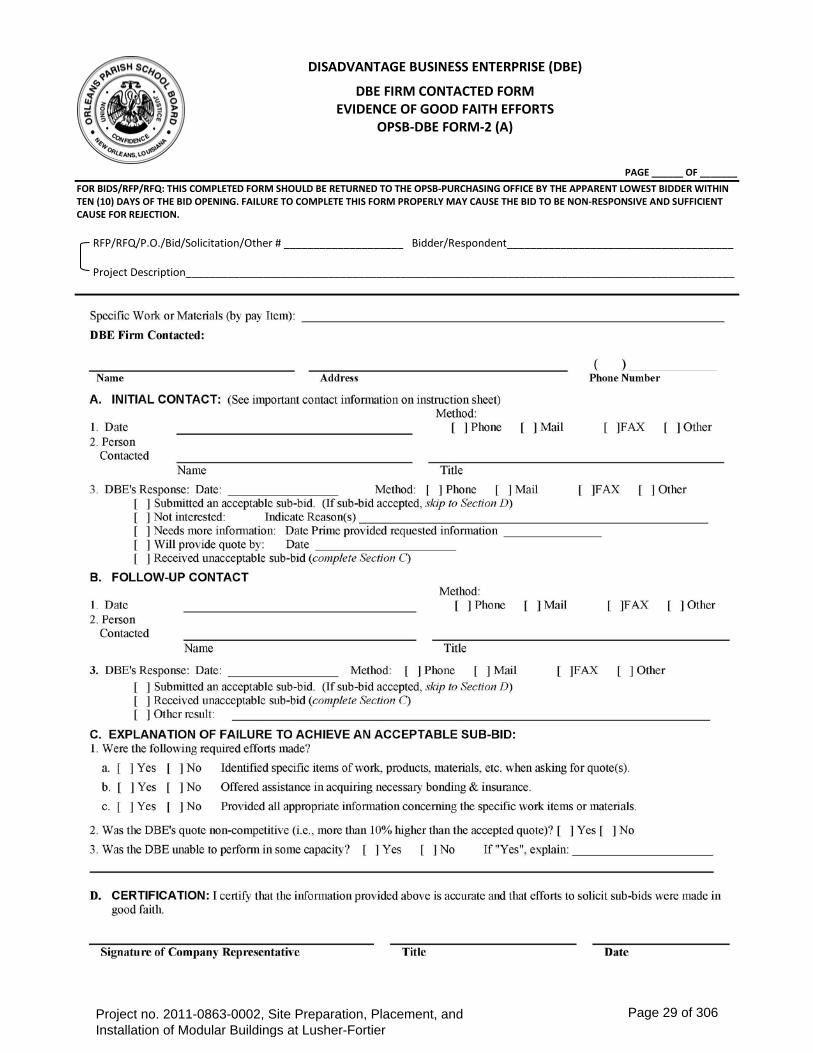
PAGE ______ OF _______
FOR BIDS/RFP/RFQ: THIS COMPLETED FORM SHOULD BE RETURNED TO THE OPSB-PURCHASING OFFICE BY THE APPARENT LOWEST BIDDER WITHIN TEN (10) DAYS OF THE BID OPENING. FAILURE TO COMPLETE THIS FORM PROPERLY MAY CAUSE THE BID TO BE NON-RESPONSIVE AND SUFFICIENT CAUSE FOR REJECTION. RFP/RFQ/P.O./Bid/Solicitation/Other # ____________________ Bidder/Respondent______________________________________ Project Description____________________________________________________________________________________________
DISADVANTAGE BUSINESS ENTERPRISE (DBE)
DBE FIRM CONTACTED FORM EVIDENCE OF GOOD FAITH EFFORTS
OPSB-DBE FORM-2 (A)
Project no. 2011-0863-0002, Site Preparation, Placement, and Installation of Modular Buildings at Lusher-Fortier
Page 29 of 306
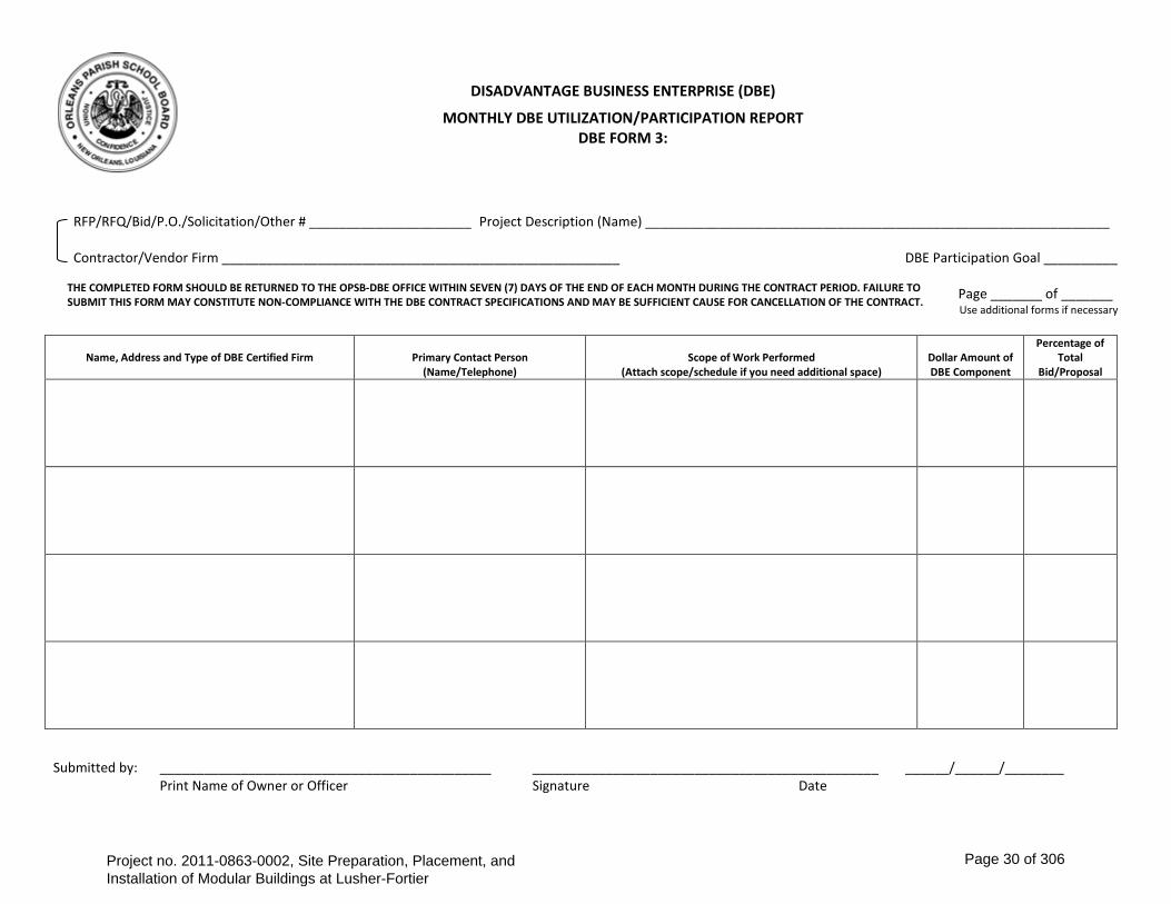
RFP/RFQ/Bid/P.O./Solicitation/Other # ______________________ Project Description (Name) _______________________________________________________________ Contractor/Vendor Firm ______________________________________________________ DBE Participation Goal __________ Page _______ of _______
Use additional forms if necessary
Name, Address and Type of DBE Certified Firm
Primary Contact Person (Name/Telephone)
Scope of Work Performed (Attach scope/schedule if you need additional space)
Dollar Amount of DBE Component
Percentage of Total
Bid/Proposal
Submitted by: _____________________________________________ _______________________________________________ ______/______/________ Print Name of Owner or Officer Signature Date
DISADVANTAGE BUSINESS ENTERPRISE (DBE)
MONTHLY DBE UTILIZATION/PARTICIPATION REPORT DBE FORM 3:
THE COMPLETED FORM SHOULD BE RETURNED TO THE OPSB-DBE OFFICE WITHIN SEVEN (7) DAYS OF THE END OF EACH MONTH DURING THE CONTRACT PERIOD. FAILURE TO SUBMIT THIS FORM MAY CONSTITUTE NON-COMPLIANCE WITH THE DBE CONTRACT SPECIFICATIONS AND MAY BE SUFFICIENT CAUSE FOR CANCELLATION OF THE CONTRACT.
Project no. 2011-0863-0002, Site Preparation, Placement, and Installation of Modular Buildings at Lusher-Fortier
Page 30 of 306
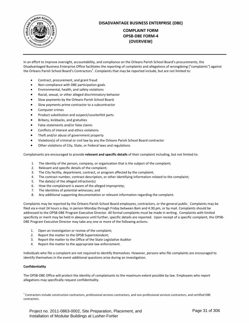
In an effort to improve oversight, accountability, and compliance on the Orleans Parish School Board’s procurements, the Disadvantaged Business Enterprise Office facilitates the reporting of complaints and allegations of wrongdoing ("complaints") against the Orleans Parish School Board’s Contractors1. Complaints that may be reported include, but are not limited to:
• Contract, procurement, and grant fraud • Non-compliance with DBE participation goals • Environmental, health, and safety violations • Racial, sexual, or other alleged discriminatory behavior • Slow payments by the Orleans Parish School Board. • Slow payments prime contractor to a subcontractor • Computer crimes • Product substitution and suspect/counterfeit parts • Bribery, kickbacks, and gratuities • False statements and/or false claims • Conflicts of interest and ethics violations • Theft and/or abuse of government property • Violation(s) of criminal or civil law by any the Orleans Parish School Board contractor • Other violations of City, State, or Federal laws and regulations
Complainants are encouraged to provide relevant and specific details of their complaint including, but not limited to:
1. The identity of the person, company, or organization that is the subject of the complaint; 2. Relevant and specific details of the complaint; 3. The City facility, department, contract, or program affected by the complaint; 4. The contract number, contract description, or other identifying information related to the complaint; 5. The date(s) of the alleged infraction(s) 6. How the complainant is aware of the alleged impropriety; 7. The identities of potential witnesses; and 8. Any additional supporting documentation or relevant information regarding the complaint.
Complaints may be reported by the Orleans Parish School Board employees, contractors, or the general public. Complaints may be filed via e-mail 24 hours a day, in person Monday through Friday between 8am and 4:30.pm, or by mail. Complaints should be addressed to the OPSB-DBE Program Executive Director. All formal complaints must be made in writing. Complaints with limited specificity or merit may be held in abeyance until further, specific details are reported. Upon receipt of a specific complaint, the OPSB-DBE Program Executive Director may take any one or more of the following actions:
1. Open an investigation or review of the complaint; 2. Report the matter to the OPSB Superintendent; 3. Report the matter to the Office of the State Legislative Auditor 4. Report the matter to the appropriate law enforcement.
Individuals who file a complaint are not required to identify themselves. However, persons who file complaints are encouraged to identify themselves in the event additional questions arise during an investigation. Confidentiality The OPSB-DBE Office will protect the identity of complainants to the maximum extent possible by law. Employees who report allegations may specifically request confidentiality.
1 Contractors include construction contractors, professional services contractors, and non-professional services contractors, and certified DBE contractors.
DISADVANTAGE BUSINESS ENTERPRISE (DBE)
COMPLAINT FORM OPSB-DBE FORM-4
(OVERVIEW)
Project no. 2011-0863-0002, Site Preparation, Placement, and Installation of Modular Buildings at Lusher-Fortier
Page 31 of 306

RFP/RFQ/P.O./Bid/Solicitation/Other # ___________________________ Project Description____________________________________________________________________________________________ Check one or more box: Contract, procurement, and grant fraud Non-compliance with DBE participation goals Environment, health, and safety violations Racial, sexual, or other alleged discriminatory behavior Slow payments by the OPSB Slow payments prime contractor to a subcontractor Computer crimes Product substitution and suspect/counterfeit parts
Bribery, kickbacks, and gratuities False statements and/or false claims Conflicts of interest and ethics violations Theft and/or abuse of government property Violation(s) of criminal or civil law by OPSB’s contractor Other violations of City, State, or Federal laws and
regulations
Please provide relevant and specific details of your complaint and/or allegation of wrongdoing below. If you have documents to support your complaint or allegation of wrongdoing, attach them to this document. If you need additional space please use a separate page and attach it to this document. ______________________________________________________________________________________________________________
______________________________________________________________________________________________________________
______________________________________________________________________________________________________________
______________________________________________________________________________________________________________
______________________________________________________________________________________________________________
Complainant (Name and/or Firm): __________________________________________________________________________________ Address: _________________________________________________________ City ____________________ State _____ Zip ______ Telephone: ____________________ Fax: ___________________ E-Mail: ________________________________________ By: _______________________________________________ ________________________________________ _____/_____/______ (Signature) (Title) (Date)
Office Use Only Date received by OPSB ____/____/____ Received by _____________ (Initials) Initial Action Taken on ____/____/____
DISADVANTAGE BUSINESS ENTERPRISE (DBE)
DBE COMPLAINT FORM OPSB-DBE FORM-4
Initial Action Taken Opened an investigation or review of the complaint; Referred the matter to the full Board; Reported the matter to the OPSB Superintendent; Reported the matter to law enforcement.
Project no. 2011-0863-0002, Site Preparation, Placement, and Installation of Modular Buildings at Lusher-Fortier
Page 32 of 306

BID/RFP/RFQ/P.O./Solicitation/Other# _____________________________ Current Date ______/______/_________ Project Description ________________________________________________________________________________
_____________________________________________________________
I hereby request that the DBE participation goal, pursuant to the Orleans Parish School Board’s DBE Policy be waived on the above-referenced project for the following reason(s):
See DBE Form-2: Evidence of Good Faith Efforts and supporting documentation attached.
___________________________________________________________________________________________________
___________________________________________________________________________________________________
___________________________________________________________________________________________________
___________________________________________________________________________________________________
___________________________________________________________________________________________________
___________________________________________________________________________________________________
___________________________________________________________________________________________________ Requested By _______________________________________________ , ____________________________ _____/_____/______ (Signature) (Title) (Date) __________________________ _____________________________________ Telephone E-Mail Reviewed By (Office of OPSB-DBE) _______________________________________________ , ____________________________ _____/_____/______ (Signature) (Title) (Date) Approved By (Superintendent) _______________________________________________ , ____________________________ _____/_____/______ (Signature) (Title) (Date)
DISADVANTAGE BUSINESS ENTERPRISE (DBE) GOALS
REQUEST FOR WAIVER OF DBE REQUIREMENT OPSB-DBE FORM 5
Project no. 2011-0863-0002, Site Preparation, Placement, and Installation of Modular Buildings at Lusher-Fortier
Page 33 of 306
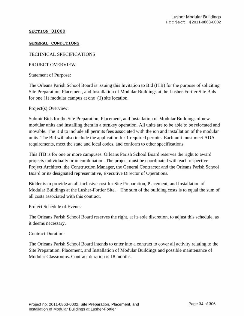
Lusher Modular Buildings
Project #2011-0863-0002
SECTION 01000 GENERAL CONDITIONS TECHNICAL SPECIFICATIONS
PROJECT OVERVIEW
Statement of Purpose:
The Orleans Parish School Board is issuing this Invitation to Bid (ITB) for the purpose of soliciting Site Preparation, Placement, and Installation of Modular Buildings at the Lusher-Fortier Site Bids for one (1) modular campus at one (1) site location.
Project(s) Overview:
Submit Bids for the Site Preparation, Placement, and Installation of Modular Buildings of new modular units and installing them in a turnkey operation. All units are to be able to be relocated and movable. The Bid to include all permits fees associated with the ion and installation of the modular units. The Bid will also include the application for 1 required permits. Each unit must meet ADA requirements, meet the state and local codes, and conform to other specifications.
This ITB is for one or more campuses. Orleans Parish School Board reserves the right to award projects individually or in combination. The project must be coordinated with each respective Project Architect, the Construction Manager, the General Contractor and the Orleans Parish School Board or its designated representative, Executive Director of Operations.
Bidder is to provide an all-inclusive cost for Site Preparation, Placement, and Installation of Modular Buildings at the Lusher-Fortier Site. The sum of the building costs is to equal the sum of all costs associated with this contract.
Project Schedule of Events:
The Orleans Parish School Board reserves the right, at its sole discretion, to adjust this schedule, as it deems necessary.
Contract Duration:
The Orleans Parish School Board intends to enter into a contract to cover all activity relating to the Site Preparation, Placement, and Installation of Modular Buildings and possible maintenance of Modular Classrooms. Contract duration is 18 months.
Project no. 2011-0863-0002, Site Preparation, Placement, and Installation of Modular Buildings at Lusher-Fortier
Page 34 of 306
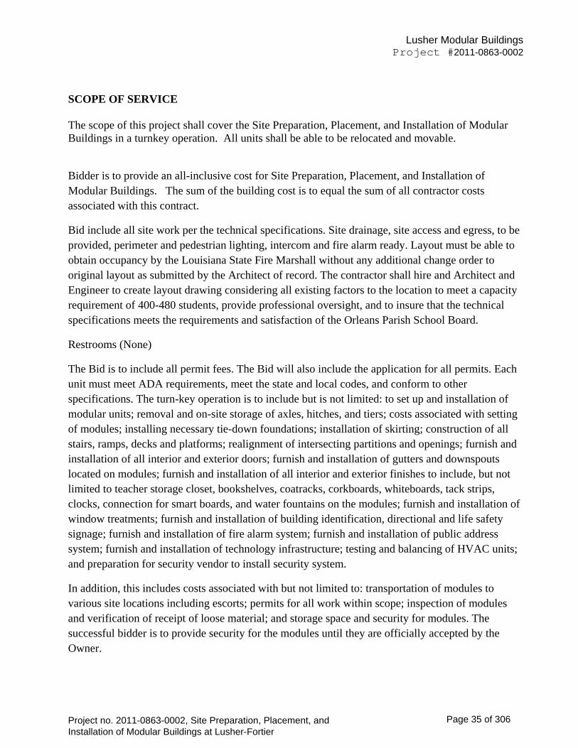
Lusher Modular Buildings
Project #2011-0863-0002
SCOPE OF SERVICE The scope of this project shall cover the Site Preparation, Placement, and Installation of Modular Buildings in a turnkey operation. All units shall be able to be relocated and movable.
Bidder is to provide an all-inclusive cost for Site Preparation, Placement, and Installation of Modular Buildings. The sum of the building cost is to equal the sum of all contractor costs associated with this contract.
Bid include all site work per the technical specifications. Site drainage, site access and egress, to be provided, perimeter and pedestrian lighting, intercom and fire alarm ready. Layout must be able to obtain occupancy by the Louisiana State Fire Marshall without any additional change order to original layout as submitted by the Architect of record. The contractor shall hire and Architect and Engineer to create layout drawing considering all existing factors to the location to meet a capacity requirement of 400-480 students, provide professional oversight, and to insure that the technical specifications meets the requirements and satisfaction of the Orleans Parish School Board.
Restrooms (None)
The Bid is to include all permit fees. The Bid will also include the application for all permits. Each unit must meet ADA requirements, meet the state and local codes, and conform to other specifications. The turn-key operation is to include but is not limited: to set up and installation of modular units; removal and on-site storage of axles, hitches, and tiers; costs associated with setting of modules; installing necessary tie-down foundations; installation of skirting; construction of all stairs, ramps, decks and platforms; realignment of intersecting partitions and openings; furnish and installation of all interior and exterior doors; furnish and installation of gutters and downspouts located on modules; furnish and installation of all interior and exterior finishes to include, but not limited to teacher storage closet, bookshelves, coatracks, corkboards, whiteboards, tack strips, clocks, connection for smart boards, and water fountains on the modules; furnish and installation of window treatments; furnish and installation of building identification, directional and life safety signage; furnish and installation of fire alarm system; furnish and installation of public address system; furnish and installation of technology infrastructure; testing and balancing of HVAC units; and preparation for security vendor to install security system.
In addition, this includes costs associated with but not limited to: transportation of modules to various site locations including escorts; permits for all work within scope; inspection of modules and verification of receipt of loose material; and storage space and security for modules. The successful bidder is to provide security for the modules until they are officially accepted by the Owner.
Project no. 2011-0863-0002, Site Preparation, Placement, and Installation of Modular Buildings at Lusher-Fortier
Page 35 of 306

Lusher Modular Buildings
Project #2011-0863-0002
The successful Bidder is responsible for final connection of utilities. They will be responsible for all utility connections to the available public systems: electric, water and sewer, telephone, security (monitoring). The successful bidder shall be responsible for preparing the building(s) for utility hook-ups, installing interconnecting wiring, disconnects, electrical panels and plumbing, arranging inspections, coordinating requirements with local utility companies and OPSB (Orleans Parish School Board Facilities Staff) as necessary to insure that all systems are installed and interconnected with local utility networks in time to satisfy the contract completion date. The site contractor will bring all utilities to within (5) feet of each building.
SITE LOCATIONS:
Lusher (Fortier) Charter High School
5624 Freret Street
New Orleans, Louisiana
MISCELLANEOUS
Notice to Proceed
The successful Bidder(s) shall, within five (5) days of Notification to Proceed, prepare and submit to the Orleans Parish School Board or their Designated Representative for approval three (3) copies of a practicable schedule showing the proposed activities. The schedule l must be submitted in Microsoft Project 2000 format I may be a formal CPM computerized schedule or a progress chart in a gnatt chart format of suitable scale to indicate appropriately the percentage of Work scheduled for completion by any given date during the period. In either case the basic information should be the same as the schedule chart must contain as a minimum: a list of the different types of fabrication and installation activities, show the logical dependencies (ties) to indicate what work must be accomplished before other work can begin, show when you propose to start and complete each work activity or work element I calculate the I weighting" or relative worth each work activity or work element is of the total project either as a percent or dollar amount. If, in the opinion of the Orleans Parish School Board or their Designated Representative, the successful Bidder falls behind the approved schedule, the successful Bidder shall take the steps necessary to improve its progress, including those that may be required by the Orleans Parish School Board or their Designated Representative without additional cost to OPSB. The schedule can be extended or modified upon approval of the Orleans Parish School Board or their Designated Representative.
SPECIAL CONDITIONS:
Project start-up period:
Project no. 2011-0863-0002, Site Preparation, Placement, and Installation of Modular Buildings at Lusher-Fortier
Page 36 of 306
Lusher Modular Buildings
Project #2011-0863-0002
The first five (5) calendar days following Project award will be designated a Project start-up period. This period is to be used for initial fact-finding, identification of team members, and Project kick-off meetings.
Correspondence:
All project correspondence will be addressed to the Project Coordinator/Planner, to be identified.
Project Completion:
The project will be considered complete when: the successful Bidder formally submits, by written correspondence all required Documents in the number and format acceptable to Orleans Parish School Board or their Designated Representative. After receipt and review of these documents a formal letter of acceptance is sent to the successful Bidder. The submittal of final billing requirements after the acceptance of any and all required Documents.
GENERAL REQUIREMENTS AND INFORMATION
INQUIRIES
All inquiries must be in writing and sent to:
Mr. Leslie J. Rey Purchasing/Ancillary Services Director Orleans Parish School Board 3520 General De Gaulle Drive Suite 5078 New Orleans, LA 70114 (504) 304- 56454 [email protected]
AVAILABILITY OF RECORDS
The successful Bidder shall make available at its office at all reasonable times all technical and financial materials relevant to this Project for examination, audit, or reproduction, until three (3) years after final payment under this Document. The successful Bidder shall maintain and the Orleans Parish School Board shall have the right to examine and audit books, records, documents, and other evidence and accounting procedures and practices, sufficient to reflect properly all expenditures claimed to have been incurred or anticipated to be incurred in performing this, Project. This right of examination shall include inspection at all reasonable times of the successful Bidder’s facility or parts of them, engaged in performing the Project and whatever applicable records are maintained. If the Project is completely or partially terminated, the records relating to the work terminated shall be made available for three (3) years after any resulting final termination settlement.
Project no. 2011-0863-0002, Site Preparation, Placement, and Installation of Modular Buildings at Lusher-Fortier
Page 37 of 306

Lusher Modular Buildings
Project #2011-0863-0002
GENERAL REQUIREMENTS
1. Complete of Scope of Work:
School facilities shall be delivered to the Orleans Parish School Board of New Orleans or designee for occupancy by faculty and students by July 14, 2014.
If not complete, an $8,000 per day liquidated damage assessment shall be brought upon the selected Bidder. The selected Bidder shall be responsible for all material, labor, and documentation required for the installation of a complete turn-key modular unit at the designated site.
2. Cost containment:
Cost containment, and rapid and economical fabrication and installation should be a high priority resulting in the lowest possible bid proposal that falls within the construction budget limits assigned to the project.
3. Successful Bidder staffing requirements:
The successful Bidder will assign a dedicated project lead person to this project. The number and specialties all supporting staff members must be provided upon receipt of bid.
4. Meetings:
The successful Bidder may be asked to conduct or participate in informational and/or planning meetings. Presentations may be formal or informal based on the subject and or group involved. Potential audiences are Orleans Parish School Board management and various community groups. The number and nature will be flexible.
The selected Bidder is to attend a weekly project meeting and to provide assistance in generating meeting agenda before said meetings and distribution of meeting minutes within 48 hours following said meeting.
Selected Bidder to provide electronic actual vs. planned schedule and cost reports at each weekly meetings {updating status of actual work and cost vs. planned work and cost. The Owner or designee may mandate reporting formats and requirements.
5. Information requests:
The successful Bidder will be responsible for providing periodic information at the request of Orleans Parish School Board. Requests may ask for budget and cost estimates, schedule status, installation clarifications, project overviews or any other topic that may concern this project. Any reports or information sent electronically shall be in the latest Microsoft Word
Project no. 2011-0863-0002, Site Preparation, Placement, and Installation of Modular Buildings at Lusher-Fortier
Page 38 of 306

Lusher Modular Buildings
Project #2011-0863-0002
format. The Project Coordinator/Planner will be the initial contact person for all Orleans Parish School Board information, unless otherwise directed.
The successful Bidder is to provide weekly a proposed cost loaded construction project schedule and job duration in a format to be specified format to be determined. This format includes but is not limited to Primavera Project Planner (P3) format.
The successful Bidder is to maintain a Material Status Log to track status and location of any and all materials. Owner reserves the right to visit the fabricator's factory or other location to verify progress.
The successful Bidder is to document and annotate a digital photographic inventory of the project; including photography of conditions before, during, and after work is completed. The photographic inventory will be submitted in support of payment requests.
6. Fire-safety and life-safety
Safety devices, fire extinguishers, safe exits, exit lights, exit hardware, lighting, emergency alarm system and the egress, emergency like shall be provided in accordance with State and local requirements.
Selected Bidder is responsible for delivering any and all life safety features / requirements including fire alarm system, fire extinguishers, fire suppression systems, and public announcement systems to the Owner in compliance with local and state fire code and in accordance with adopted NFPA Standards currently adopted by the Louisiana State Fire Marshal as well as the State's Uniform Construction Code. Selected Bidder to provide line item detail of steps taken to deliver the aforementioned systems in full operating condition at the request of the owner. Shop drawing approval by the Office of the State Fire Marshal shall be the responsibility of the selected bidder.
Selected Bidder must supply an emergency lighting system that satisfies all local building code and fire and life safety code requirements.
7. Standards:
The successful Bidder will incorporate any standards or equipment used by Orleans Parish School Board that meet or exceed State of Louisiana standards. The successful Bidder is encouraged to offer alternatives that make the Project aesthetically, functionally and/or economically more efficient.
The selected Bidder is required to meet or pass any and all certifications mandated by and/or State Fire Marshal and any/all required agencies. All work shall comply with IBC 2012 standards and all applicable State and local building codes and adopted fire and life safety codes and standards.
Project no. 2011-0863-0002, Site Preparation, Placement, and Installation of Modular Buildings at Lusher-Fortier
Page 39 of 306
Lusher Modular Buildings
Project #2011-0863-0002
Modular building finished floor heights shall comply with FEMA flood insurance minimum height requirements and restrictions.
The classroom modules shall be arranged in double loaded corridor fashion whenever possible. All corridors shall be a minimum of 8ft in width. All corridors are to be conditioned areas.
8. Modulars:
Modular building performance specifications are listed within this ITB. The successful Bidder may substitute other steel framed or concrete framed modular manufactured products that are similar and meet the same intent of what is specified with approval of Owner.
Selected bidder shall utilize one manufacturer of modules per group (i.e. classrooms, administration) in order to maintain a uniformity of appearance. Selected bidder may only use multiple modular suppliers if approved by Owner. Prior to the issuance of a work order, approval of modular manufacturer must be obtained by Owner. If different manufacturers are used the exterior skin shall be similar if not identical subject to owner's approval.
Modular units must meet or exceed local wind load design requirements.
9. Test f and space alignment
The successful Bidder shall test-fit the planned furniture for appropriate space alignment. In addition, the successful bidder shall provide proper and rough-in for HVAC/plumbing/electrical connections so as to minimize costly delays and changes when dealing with incomplete information.
SPECIAL REQUIREMENTS AND SPECIFICATIONS
Modular building performance specifications are listed within this ITB. The successful Bidder, with Owner approval, may substitute other steel framed or concrete framed modular manufactured products that are similar and meet the same intent of what is specified. Selected bidder shall utilize one manufacturer of modules per group (i.e. classrooms, foodservice) in order to maintain a uniformity of appearance. Selected bidder may only use multiple modular suppliers if approved by Owner. Prior to the issuance of a purchase order, approval of modular manufacturer must be obtained by Owner.
General Conditions
Project no. 2011-0863-0002, Site Preparation, Placement, and Installation of Modular Buildings at Lusher-Fortier
Page 40 of 306
Lusher Modular Buildings
Project #2011-0863-0002
Selected Bidder shall be responsible for Site Preparation, Placement, and Installation of Modular Buildings at the Lusher-Fortier Site. Selected bidder shall bear the cost and make all arrangements for any and all equipment installation.
Selected Bidder shall be responsible for a final cleaning of all trailers and removal of site debris.
CODES AND STANDARDS:
Successful bidder must comply with the following:
A. Wind: 130-MPH exposure "C" and 146-MPH exposure "BII
B. International Building Code, 2006
C. International Plumbing Code
D. International Mechanical Code
E. National Electrical Code
F. International Energy Conservation Code
G. Louisiana Architect Seal
H. Louisiana Fire Marshal Approval
I. Louisiana Department of Health Approval
J. Louisiana Building Code compliant
K. SREF requirements compliant
L. Have a CRA/DCA approval and insignia
M. Meet Type IV non-combustible construction requirements
FIRE ALARM SPECIFICATIONS
INTELLIGENT REPORTING FIRE DETECTION SYSTEM
PART 1.0 GENERAL
1.1 DESCRIPTION:
A. This section of the specification includes the furnishing, installation, connection and testing of the microprocessor controlled, intelligent reporting fire alarm equipment required to form a
Project no. 2011-0863-0002, Site Preparation, Placement, and Installation of Modular Buildings at Lusher-Fortier
Page 41 of 306
Lusher Modular Buildings
Project #2011-0863-0002
complete, operative, coordinated system. It shall include, but not be limited to, alarm initiating devices, alarm notification appliances, Fire Alarm Control Panel (FACP), auxiliary control devices, and wiring as shown on the drawings and specified herein.
B. The fire alarm system shall comply with requirements of 2003 NFPA Standard 72 for Protected Premises Signaling Systems except as modified and supplemented by this specification. The system shall be electrically supervised and monitor the integrity of all conductors.
C. The FACP and peripheral devices shall be manufactured 100% by a single U.S. manufacturer (or division thereof).
D. The system and its components shall be Underwriters Laboratories, Inc. listed under the appropriate UL testing standard as listed herein for fire alarm applications and shall be in compliance with the UL listing.
E. The installing company shall employ NICET (minimum Level III Fire Alarm Technology) technicians on site to guide the final check-out and to ensure the systems integrity.
1. 2 SCOPE:
A. A new intelligent reporting, microprocessor controlled fire detection system shall be installed in accordance to the project specifications and drawings.
B. Bas Performance:
1. Alarm, trouble and supervisory signals from all intelligent reporting devices shall be encoded
on NFPA Style 7 (Class A) Signaling Line Circuits (SLC).
2. Initiation Device Circuits (IDC) shall be wire Class B (NFPA Style B) as part of an addressable
device connected by the SLC Circuit.
3. Notification Appliance Circuits (NAC) shall be wired Class B (NFPA Style Y) as part of an addressable device connected by the SLC Circuit.
4. Digitized electronic signals shall employ check digits or multiple polling.
5. A single ground or open on the system signaling line circuit shall not cause system malfunction, loss of operating power or the ability to report an alarm.
6. Alarm signals arriving at the main FACP shall not be lost following a primary power failure (or outage) until the alarm signal is processed and recorded.
7. The FACP shall have the capacity to transmit an alarm to an offsite monitor facility.
C. BASIC SYSTEM FUNCTIONAL OPERATION
Project no. 2011-0863-0002, Site Preparation, Placement, and Installation of Modular Buildings at Lusher-Fortier
Page 42 of 306

Lusher Modular Buildings
Project #2011-0863-0002
When a fire alarm condition is detected and reported by one of the system initiating devices, the following functions shall immediately occur:
1. The system alarm LED on the FACP shall flash.
2. A local piezo electric signal in the control panel shall sound.
3. A backlit 80 character LCD display on the FACP shall indicate all information associated fire alarm condition, including the type of alarm point and its location within the protected premises.
4. Printing on the FACP and history storage equipment shall log the information associated each new fire alarm control panel condition, along with time and date of occurrence.
5. All system output programs assigned via control-by-event interlock programming to be activated by the particular point in alarm shall be executed, and the associated system outputs (alarm notification appliances and/or relays) shall be activated.
6. Provide a smoke detector above the panel.
1.3 SUBMITTALS
1. Two copies of all submittals shall be submitted to the Owner for review.
2. All references to manufacturer's model numbers and other pertinent information herein is intended to establish minimum standards of performance, function and quality. Equivalent compatible ULlisted equipment from other manufacturers may be substituted for the specified equipment as long as the minimum standards are met.
3. For equipment other than that specified, the contractor shall supply proof that such substitute equipment equals or exceeds the features, functions, performance, and quality of the specified equipment.
B. Shop Drawings:
1. Sufficient information, shall be included to determine drawings and specifications. presented, compliance with
2. Include manufacturer's name (s), model numbers, ratings, power requirements, equipment layout, device arrangement, complete wiring point-to-point diagrams, and conduit layouts.
C. Manuals:
1. Submit simultaneously with the shop drawings, complete operating and maintenance manuals listing the manufacturer's name(s), luding technical data sheets.
Project no. 2011-0863-0002, Site Preparation, Placement, and Installation of Modular Buildings at Lusher-Fortier
Page 43 of 306

Lusher Modular Buildings
Project #2011-0863-0002
2. Wiring diagrams shall indicate for each device and the interconnections items of equipment.
D. Software Modifications:
Wiring between the
1. Provide the services of a factory trained and authorized technician to perform all system software
modifications, upgrades or changes. Response t of the technician to the site shall not exceed 4 hours.
2. Provide all hardware, software, programming tools and documentation necessary to modify the fire alarm system on site. Modification includes addition 139 and deletion of devices, circuits, zones and changes to system operation and custom label changes for devices or zones. The system structure and software shall place no limit on the type or extent of software modifications on-site. Modification of software shall not require power-down of the system or loss of system fire protection while modifications are being made.
E. Certifications:
Together with the shop drawing submittal, submit a certification from the major equipment manufacturer indicating that the proposed supervisor of the installation and the proposed performer of contract maintenance is an authorized representative of the major equipment manufacturer. Include names and addresses in the certification.
1.4 GUARANTY:
All work performed and all material and equipment furnished under this contract shall be free from defects and shall remain so a period of at least one (1) year from the date of acceptance. The full cost of maintenance, labor and materials required to correct any defect during one year period shall be included.
1.5 POST CONTRACT MAINTENANCE:
A. Complete maintenance and repair service for the fire alarm system shall be provided as part of this contract from a factory trained authorized and appropriately licensed representative of the manufacturer of the major equipment for a period of five (5) years after expiration of the guaranty.
1.7 APPLICABLE STANDARDS AND SPECIFICATIONS:
The specifications and standards this specification. The system shall latest issue of these standards. below form a part of fully comply with the:
A. National Fire Protection Association (NFPA)- USA:
No. 72-2003 National Fire Alarm Code
Project no. 2011-0863-0002, Site Preparation, Placement, and Installation of Modular Buildings at Lusher-Fortier
Page 44 of 306

Lusher Modular Buildings
Project #2011-0863-0002
No. 101 Fire Safety Code 140
B. Underwriters Laboratories Inc. (UL) - USA:
No. 268 Smoke Detectors for Fire Protective Signaling Systems
No. 864 Control Units for re Protective Signal Systems
No. 268A Smoke Detectors for Duct Applications
No. 521 Heat Detectors for Fire Protective
No. 464 Audible Signaling Appliances
No. 38 Manually Actuated Signaling Boxes
No. 1971 Visual Notification Appliances
C. Local and State Building Codes.
D . All requirements of the Authority Jurisdiction (AHJ).
QUALITY ASSURANCE
All items of equipment including wire and cable shall be designed by the manufacturer to function as a complete system and shall be accompanied by the manufacturer's complete service notes and drawings detailing all interconnections. The contractor shall be an established communications and electronics contractor that has had and currently maintains a locally run and operated business for at least five years. The contractor shall utilize a duly authorized distributor of the equipment supplied for this project location with full manufacturer's warranty privileges. The contractor shall show satisfactory evidence, upon request, that the supplier maintains a fully equipped service organization capable of furnishing adequate inspection and service to the system. The supplier shall maintain at his facility the necessary spare parts in the proper proportion as recommended by the manufacturer to maintain and service the equipment being supplied. Electrical applicable including, Component Standard: Provide work complying with requirements of NFPA 70 "National Electrical Code"
Installation and startup of all systems shall be under the direct supervision of a local agency regularly engaged installation, repair, and maintenance of such systems. The supplier shall be accredited by the proposed equipment manufacturers and be prepared to offer a service contract for system maintenance on completion of the guarantee period and provide the names, locations, and size of ten (10) recent successful installations the area. The agency providing equipment shall be responsible for providing all specified equipment and mentioned services for all equipment as specified herein. The agency must be a local authorized distributor of all specified equipment for
Project no. 2011-0863-0002, Site Preparation, Placement, and Installation of Modular Buildings at Lusher-Fortier
Page 45 of 306
Lusher Modular Buildings
Project #2011-0863-0002
single source of responsibility and shall provide documents proving such. The agency must provide written proof that the agency is adequately staffed with factory-trained technicians for all of the specified equipment. The agency must have established business for and currently be providing all services for the equipment to be provided for a minimum of 10 years. The contractor shall guarantee availability of local service by factory-trained personnel of all specified equipment from an authorized distributor of all equipment specified under this section. On-the-premise maintenance shall be provided at no cost to the purchaser for a period of one (1) year (parts and labor) from date of acceptance unless damage or failure is caused by misuse, abuse, neglect, or accident. Additionally, all manufactured products are covered by a five (5) year (parts only) limited warranty from the date of acceptance. The warranty period shall begin on the date of acceptance by the owner/ OPSB. The supplier shall visit the sites and the existing conditions and field submitting a proposal. 163 familiarize himself with requirements prior to IN-SERVICE TRAINING. The contractor shall provide a minimum of 5 hours of in service training with this system. These sessions shall be broken into segments that will facilitate the training of individuals in the operation of this system. Operators Manuals and Users
Guides shall be provided at the time of this training.
PART 2 PRODUCTS
MANUFACTURERS
Manufacturers: Subject to compliance with requirements,
provide one of the following systems:
Telecenter manufactured by Rauland-Borg Corp.
The intent of this specification is to establish a standard of quality, function and features. It the responsibility of the bidder to insure that the proposed product meets or exceeds every standard set forth in these specifications. The functions and features specified are vital to the operation of this facility, therefore, the acceptance of alternate manufacturers does not release contractor from strict compliance with the requirements of this specification. The Contractor for this work shall be held to have read all of the Bidding Requirements, the General Requirements of Division 1, and Contract Proposal Forms I and in the execution of this work, he will be bound by all of the conditions and requirements therein. The contractor shall be responsible for providing a complete functional system including all necessary components whether included in this specification or not. In preparing the bid, the bidder should consider the following:
No claim will be made against the owner for any costs incurred by the bidder for any equipment demonstrations which the owner requests. Any prior approval of an alternate system does not automatically exempt the supplier from meeting the intent of these specifications. Failure to comply
Project no. 2011-0863-0002, Site Preparation, Placement, and Installation of Modular Buildings at Lusher-Fortier
Page 46 of 306

Lusher Modular Buildings
Project #2011-0863-0002
with the operational 164 and functional intent of these specifications may result in the total removal of the alternate system at the expense of the contractor.
Alternate equipment shall be considered if submitted to the specifying authority at least ten (10) days prior to bid date. Submission of an alternate shall contain engineering drawings of the system with specification sheets covering all components of the system as well as all items of this Section "SUBMITTALS. II
The system and equipment drawings and specifications sheet, shall meet all items of the specification.
SYSTEM REQUIREMENTS
GENERAL:
The system shall provide the state of the art in technology for all internal telephone and intercom communications, secondary clock corrections, and bell schedule. The system shall be easy to learn and operate. All standard system programming shall be user friendly to allow the system administrator the ability to easily program system features. Provide complete and satisfactorily operating Integrated Intercom/Communications System as described herein, using materials and equipment of types, sizes, ratings, and performances as indicated. Use materials and equipment that comply with referenced standards and manufacturer's standard design and construction, in accordance with published product information.
BUILDING TYPE REQUIREMENTS
Floor Plan Examples: Examples are for informational purposes only and may be modified
BUILDING TYPE- A classrooms with 4 classrooms with no restroom facilities
Project no. 2011-0863-0002, Site Preparation, Placement, and Installation of Modular Buildings at Lusher-Fortier
Page 47 of 306

Lusher Modular Buildings
Project #2011-0863-0002
Project no. 2011-0863-0002, Site Preparation, Placement, and Installation of Modular Buildings at Lusher-Fortier
Page 48 of 306
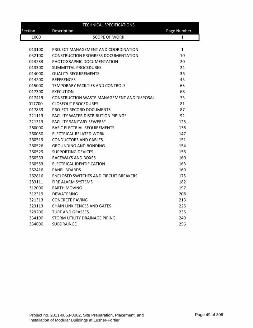
TECHNICAL SPECIFICATIONS Section Description Page Number
1000 SCOPE OF WORK 1
013100 PROJECT MANAGEMENT AND COORDINATION 1032100 CONSTRUCTION PROGRESS DOCUMENTATION 10013233 PHOTOGRAPHIC DOCUMENTATION 20013300 SUMMITTAL PROCEDURES 24014000 QUALITY REQUIREMENTS 36014200 REFERENCES 45015000 TEMPORARY FACILTIES AND CONTROLS 63017300 EXECUTION 68017419 CONSTRUCTION WASTE MANAGEMENT AND DISPOSAL 75017700 CLOSEOUT PROCEDURES 81017839 PROJECT RECORD DOCUMENTS 87221113 FACILITY WATER DISTRIBUTION PIPING* 92221313 FACILITY SANITARY SEWERS* 125260000 BASIC ELECTRIAL REQUIREMENTS 136260050 ELECTRICAL RELATED WORK 147260519 CONDUCTORS AND CABLES 151260526 GROUNDING AND BONDING 154260529 SUPPORTING DEVICES 156260533 RACEWAYS AND BOXES 160260553 ELECTRICAL IDENTIFICATION 163262416 PANEL BOARDS 169262816 ENCLOSED SWITCHES AND CIRCUIT BREAKERS 175283111 FIRE ALARM SYSTEMS 182312000 EARTH MOVING 197312319 DEWATERING 208321313 CONCRETE PAVING 213323113 CHAIN LINK FENCES AND GATES 225329200 TURF AND GRASSES 235334100 STORM UTILITY DRAINAGE PIPING 249334600 SUBDRAINGE 256
Project no. 2011-0863-0002, Site Preparation, Placement, and Installation of Modular Buildings at Lusher-Fortier
Page 49 of 306
Lusher Modular Buildings
Project #2011-0863-0002
OPSB
SECTION 013100 - PROJECT MANAGEMENT AND COORDINATION
PART 1 - GENERAL
1.1
A.
RELATED DOCUMENTS
Drawings and general provisions of the Contract, including General and Supplementary Conditions and other Division 01 Specification Sections, apply to this Section.
SUMMARY
A. Section includes administrative provisions for coordinating construction operations on Project including, but not limited to, the following:
1. 2. 3. 4.
B.
C.
General coordination procedures. Requests for Information (RFIs). Project Web site. Project meetings.
1.2
Each contractor shall participate in coordination requirements. Certain areas of responsibility are assigned to a specific contractor.
Related Requirements: 1.Division 01 Section "Construction Progress Documentation" for preparing and submitting Contractor's construction schedule. 2.Division 01 Section "Execution" for procedures for coordinating general installation and field-engineering services, including establishment of benchmarks and control points. 3.Division 01 Section "Closeout Procedures" for coordinating closeout of the Contract.
DEFINITIONS 1.3
A. RFI: Request from Owner, Construction Manager, Engineer, or Contractor seeking information required by or clarifications of the Contract Documents.
INFORMATIONAL SUBMITTALS 1.4
A. Subcontract List: Prepare a written summary identifying individuals or firms proposed for each portion of the Work, including those who are to furnish products or equipment fabricated to a special design. Include the following information in tabular form:
1.
2. 3.
Name, address, and telephone number of entity performing subcontract or supplying products. Number and title of related Specification Section(s) covered by subcontract. Drawing number and detail references, as appropriate, covered by subcontract.
PROJECT MANAGEMENT AND COORDINATION 013100 - 1
Project no. 2011-0863-0002, Site Preparation, Placement, and Installation of Modular Buildings at Lusher-Fortier
Page 50 of 306
Lusher Modular Buildings
Project #2011-0863-0002
B.
OPSB
Key Personnel Names: Within 15 days of starting construction operations, submit a list of key personnel assignments, including superintendent and other personnel in attendance at Project site. Identify individuals and their duties and responsibilities; list addresses and telephone numbers, including home, office, and cellular telephone numbers and e-mail addresses. Provide names, addresses, and telephone numbers of individuals assigned as alternates in the absence of individuals assigned to Project.
1. Post copies of list in project meeting room, in temporary field office, and by each temporary telephone. Keep list current at all times.
1.5
A.
GENERAL COORDINATION PROCEDURES
Coordination: Coordinate construction operations included in different Sections of the Specifications to ensure efficient and orderly installation of each part of the Work. Coordinate construction operations, included in different Sections, that depend on each other for proper installation, connection, and operation.
1. Schedule construction operations in sequence required to obtain the best results where installation of one part of the Work depends on installation of other components, before or after its own installation. Coordinate installation of different components to ensure maximum performance and accessibility for required maintenance, service, and repair. Make adequate provisions to accommodate items scheduled for later installation.
2.
3.
B. Coordination: Each contractor shall coordinate its construction operations with those of other contractors and entities to ensure efficient and orderly installation of each part of the Work. Each contractor shall coordinate its operations with operations, included in different Sections, that depend on each other for proper installation, connection, and operation.
1. Schedule construction operations in sequence required to obtain the best results where installation of one part of the Work depends on installation of other components, before or after its own installation. Coordinate installation of different components with other contractors to ensure maximum performance and accessibility for required maintenance, service, and repair. Make adequate provisions to accommodate items scheduled for later installation.
2.
3.
C. Prepare memoranda for distribution to each party involved, outlining special procedures required for coordination. Include such items as required notices, reports, and list of attendees at meetings.
1. Prepare similar memoranda for Owner and separate contractors if coordination of their Work is required.
D. Administrative Procedures: Coordinate scheduling and timing of required administrative procedures with other construction activities and activities of other contractors to avoid conflicts and to ensure orderly progress of the Work. Such administrative activities include, but are not limited to, the following:
1. 2.
Preparation of Contractor's construction schedule. Preparation of the schedule of values.
PROJECT MANAGEMENT AND COORDINATION 013100 - 2
Project no. 2011-0863-0002, Site Preparation, Placement, and Installation of Modular Buildings at Lusher-Fortier
Page 51 of 306

Lusher Modular Buildings
Project #2011-0863-0002
3. 4. 5. 6. 7. 8.
E.
OPSB
Installation and removal of temporary facilities and controls. Delivery and processing of submittals. Progress meetings. Pre-installation conferences. Project closeout activities. Startup and adjustment of systems.
Conservation: Coordinate construction activities to ensure that operations are carried out with consideration given to conservation of energy, water, and materials. Coordinate use of temporary utilities to minimize waste.
1. Salvage materials and equipment involved in performance of, but not actually incorporated into, the Work. See other Sections for disposition of salvaged materials that are designated as Owner's property.
1.6
A.
REQUESTS FOR INFORMATION (RFIs)
General: Immediately on discovery of the need for additional information or interpretation of the Contract Documents, Contractor shall prepare and submit an RFI in the form specified.
1.
2.
B.
Engineer will return RFIs submitted to Engineer by other entities controlled by Contractor with no response. Coordinate and submit RFIs in a prompt manner so as to avoid delays in Contractor's work or work of subcontractors.
Content of the RFI: Include a detailed, legible description of item needing information or interpretation and the following:
1. 2. 3. 4. 5. 6. 7. 8. 9. 10. 11.
12. 13.
Project name. Project number. Date. Name of Contractor. Name of Engineer and Construction Manager. RFI number, numbered sequentially. RFI subject. Specification Section number and title and related paragraphs, as appropriate. Drawing number and detail references, as appropriate. Field dimensions and conditions, as appropriate. Contractor's suggested resolution. If Contractor's suggested resolution impacts the Contract Time or the Contract Sum, Contractor shall state impact in the RFI. Contractor's signature. Attachments: Include sketches, descriptions, measurements, photos, Product Data, Shop Drawings, coordination drawings, and other information necessary to fully describe items needing interpretation.
a. Include dimensions, thicknesses, structural grid references, and details of affected materials, assemblies, and attachments on attached sketches.
C. RFI Forms: AIA Document G716 or Forms acceptable to Engineer or Owner.
PROJECT MANAGEMENT AND COORDINATION 013100 - 3
Project no. 2011-0863-0002, Site Preparation, Placement, and Installation of Modular Buildings at Lusher-Fortier
Page 52 of 306

Lusher Modular Buildings
Project #2011-0863-0002
1.
D.
OPSB
Attachments shall be electronic files in Adobe Acrobat PDF format.
Engineer's and Construction Manager's Action: Engineer and Construction Manager will review each RFI, determine action required, and respond. Allow seven working days for Engineer's response for each RFI. RFIs received by Engineer or Construction Manager after 1:00 p.m. will be considered as received the following working day.
1. The following Contractor-generated RFIs will be returned without action:
a. b. c. d.
e. f. g.
2.
3.
Requests for approval of submittals. Requests for approval of substitutions. Requests for approval of Contractor's means and methods. Requests for coordination information already indicated in the Contract Documents. Requests for adjustments in the Contract Time or the Contract Sum. Requests for interpretation of Engineer's actions on submittals. Incomplete RFIs or inaccurately prepared RFIs.
Engineer's action may include a request for additional information, in which case Engineer's time for response will date from time of receipt of additional information. Engineer's action on RFIs that may result in a change to the Contract Time or the Contract Sum may be eligible for Contractor to submit Change Proposal according to Division 01 Section "Contract Modification Procedures."
a. If Contractor believes the RFI response warrants change in the Contract Time or the Contract Sum, notify Engineer and Construction Manager in writing within 10 days of receipt of the RFI response.
E. RFI Log: Prepare, maintain, and submit a tabular log of RFIs organized by the RFI number. Submit log weekly. Include the following:
1. 2. 3. 4. 5. 6. 7.
Project name. Name and address of Contractor. Name and address of Engineer and Construction Manager. RFI number including RFIs that were returned without action or withdrawn. RFI description. Date the RFI was submitted. Date Engineer's and Construction Manager's response was received.
F. On receipt of Engineer's and Construction Manager's action, update the RFI log and immediately distribute the RFI response to affected parties. Review response and notify Engineer and Construction Manager within seven days if Contractor disagrees with response.
1.
2.
Identification of related Minor Change in the Work, Construction Change Directive, and Proposal Request, as appropriate. Identification of related Field Order, Work Change Directive, and Proposal Request, as appropriate.
PROJECT MANAGEMENT AND COORDINATION 013100 - 4
Project no. 2011-0863-0002, Site Preparation, Placement, and Installation of Modular Buildings at Lusher-Fortier
Page 53 of 306
Lusher Modular Buildings
Project #2011-0863-0002
1.7
A.
PROJECT MEETINGS
OPSB
General: Engineer and Construction Manager will schedule and conduct meetings and conferences at Project site unless otherwise indicated.
1. Attendees: Inform participants and others involved, and individuals whose presence is required, of date and time of each meeting. Notify Owner and Engineer of scheduled meeting dates and times. Agenda: Prepare the meeting agenda. Distribute the agenda to all invited attendees. Minutes: Entity responsible for conducting meeting will record significant discussions and agreements achieved. Distribute the meeting minutes to everyone concerned, including Owner, Construction Manager, and Engineer, within three days of the meeting.
2. 3.
B. Preconstruction Conference: Engineer and Construction Manager will schedule and conduct a preconstruction conference before starting construction, at a time convenient to Owner and Engineer, but no later than 15 days after execution of the Agreement.
1. 2.
Conduct the conference to review responsibilities and personnel assignments. Attendees: Authorized representatives of Owner, Construction Manager, Engineer, and their consultants; Contractor and its superintendent; major subcontractors; suppliers; and other concerned parties shall attend the conference. Participants at the conference shall be familiar with Project and authorized to conclude matters relating to the Work. Agenda: Discuss items of significance that could affect progress, including the following:
a. b. c. d. e. f. g. h. i. j. k. l. m. n. o. p. q. r. s. t. u. v. w. x. y. z.
Tentative construction schedule. Phasing. Critical work sequencing and long-lead items. Designation of key personnel and their duties. Lines of communications. Procedures for processing field decisions and Change Orders. Procedures for RFIs. Procedures for testing and inspecting. Procedures for processing Applications for Payment. Distribution of the Contract Documents. Submittal procedures. Preparation of record documents. Use of the premises. Work restrictions. Working hours. Owner's occupancy requirements. Responsibility for temporary facilities and controls. Procedures for moisture and mold control. Procedures for disruptions and shutdowns. Construction waste management and recycling. Parking availability. Office, work, and storage areas. Equipment deliveries and priorities. First aid. Security. Progress cleaning.
3.
PROJECT MANAGEMENT AND COORDINATION 013100 - 5
Project no. 2011-0863-0002, Site Preparation, Placement, and Installation of Modular Buildings at Lusher-Fortier
Page 54 of 306

Lusher Modular Buildings
Project #2011-0863-0002
4.
C.
OPSB
Minutes: Entity responsible for conducting meeting will record and distribute meeting minutes.
Pre-installation Conferences: Conduct a pre-installation conference at Project site before each construction activity that requires coordination with other construction.
1. Attendees: Installer and representatives of manufacturers and fabricators involved in or affected by the installation and its coordination or integration with other materials and installations that have preceded or will follow, shall attend the meeting. Advise Engineer, & Construction Manager of scheduled meeting dates. Agenda: Review progress of other construction activities and preparations for the particular activity under consideration, including requirements for the following:
a. b. c. d. e. f. g. h. i. j. k. l. m. n. o. p. q. r. s. t. u. v. w. x. y.
3.
4.
5.
Contract Documents. Options. Related RFIs. Related Change Orders. Purchases. Deliveries. Submittals. Review of mockups. Possible conflicts. Compatibility requirements. Time schedules. Weather limitations. Manufacturer's written instructions. Warranty requirements. Compatibility of materials. Acceptability of substrates. Temporary facilities and controls. Space and access limitations. Regulations of authorities having jurisdiction. Testing and inspecting requirements. Installation procedures. Coordination with other work. Required performance results. Protection of adjacent work. Protection of construction and personnel.
2.
Record significant conference discussions, agreements, and disagreements, including required corrective measures and actions. Reporting: Distribute minutes of the meeting to each party present and to other parties requiring information. Do not proceed with installation if the conference cannot be successfully concluded. Initiate whatever actions are necessary to resolve impediments to performance of the Work and reconvene the conference at earliest feasible date.
D. Project Closeout Conference: Engineer and Construction Manager will schedule and conduct a project closeout conference, at a time convenient to Owner and Engineer, but no later than 10 days prior to the scheduled date of Substantial Completion.
PROJECT MANAGEMENT AND COORDINATION 013100 - 6
Project no. 2011-0863-0002, Site Preparation, Placement, and Installation of Modular Buildings at Lusher-Fortier
Page 55 of 306

Lusher Modular Buildings
Project #2011-0863-0002
1.
2.
OPSB
3.
Conduct the conference to review requirements and responsibilities related to Project closeout. Attendees: Authorized representatives of Owner, Engineer & Construction Manager, and their consultants; Contractor and its superintendent; major subcontractors; suppliers; and other concerned parties shall attend the meeting. Participants at the meeting shall be familiar with Project and authorized to conclude matters relating to the Work. Agenda: Discuss items of significance that could affect or delay Project closeout, including the following:
a. b.
c. d. e. f. g. h. i.
j. k. l. m. n.
Preparation of record documents. Procedures required prior to inspection for Substantial Completion and for final inspection for acceptance. Submittal of written warranties. Requirements for completing documentation. Requirements for preparing operations and maintenance data. Requirements for delivery of material samples, attic stock, and spare parts. Requirements for demonstration and training. Preparation of Contractor's punch list. Procedures for processing Applications for Payment at Substantial Completion and for final payment. Submittal procedures. Coordination of separate contracts. Owner's partial occupancy requirements. Installation of Owner's furniture, fixtures, and equipment. Responsibility for removing temporary facilities and controls.
4.
E.
Minutes: Entity conducting meeting will record and distribute meeting minutes.
Progress Meetings: Construction Manager will conduct progress meetings at weekly intervals.
1. 2.
Coordinate dates of meetings with preparation of payment requests. Attendees: In addition to representatives of Owner, Construction Manager, and Engineer, each contractor, subcontractor, supplier, and other entity concerned with current progress or involved in planning, coordination, or performance of future activities shall be represented at these meetings. All participants at the meeting shall be familiar with Project and authorized to conclude matters relating to the Work. Agenda: Review and correct or approve minutes of previous progress meeting. Review other items of significance that could affect progress. Include topics for discussion as appropriate to status of Project.
a. Contractor's Construction Schedule: Review progress since the last meeting. Determine whether each activity is on time, ahead of schedule, or behind schedule, in relation to Contractor's construction schedule. Determine how construction behind schedule will be expedited; secure commitments from parties involved to do so. Discuss whether schedule revisions are required to ensure that current and subsequent activities will be completed within the Contract Time.
1)
b.
Review schedule for next period.
3.
Review present and future needs of each entity present, including the following:
PROJECT MANAGEMENT AND COORDINATION 013100 - 7
Project no. 2011-0863-0002, Site Preparation, Placement, and Installation of Modular Buildings at Lusher-Fortier
Page 56 of 306
Lusher Modular Buildings
Project #2011-0863-0002
1) 2) 3) 4) 5) 6) 7) 8) 9) 10) 11) 12) 13) 14) 15) 16) 17) 18) 19) 20)
4.
Interface requirements. Sequence of operations. Resolution of BIM component conflicts. Status of submittals. Status of documentation. Deliveries. Off-site fabrication. Access. Site utilization. Temporary facilities and controls. Progress cleaning. Quality and work standards. Status of correction of deficient items. Field observations. Status of RFIs. Status of proposal requests. Pending changes. Status of Change Orders. Pending claims and disputes. Documentation of information for payment requests.
OPSB
Minutes: Entity responsible for conducting the meeting will record and distribute the meeting minutes to each party present and to parties requiring information.
a. Schedule Updating: Revise Contractor's construction schedule after each progress meeting where revisions to the schedule have been made or recognized. Issue revised schedule concurrently with the report of each meeting.
F. Coordination Meetings: Engineer & Construction Manager will conduct [Project coordination meetings at bi-monthly intervals. Project coordination meetings are in addition to specific meetings held for other purposes, such as progress meetings and pre-installation conferences.
1. Attendees: In addition to representatives of Owner, Construction Manager, and Engineer, each contractor, subcontractor, supplier, and other entity concerned with current progress or involved in planning, coordination, or performance of future activities shall be represented at these meetings. All participants at the meetings shall be familiar with Project and authorized to conclude matters relating to the Work. Agenda: Review and correct or approve minutes of the previous coordination meeting. Review other items of significance that could affect progress. Include topics for discussion as appropriate to status of Project.
a. Combined Contractor's Construction Schedule: Review progress since the last coordination meeting. Determine whether each contract is on time, ahead of schedule, or behind schedule, in relation to combined Contractor's construction schedule. Determine how construction behind schedule will be expedited; secure commitments from parties involved to do so. Discuss whether schedule revisions are required to ensure that current and subsequent activities will be completed within the Contract Time. Schedule Updating: Revise combined Contractor's construction schedule after each coordination meeting where revisions to the schedule have been made or recognized. Issue revised schedule concurrently with report of each meeting.
2.
b.
PROJECT MANAGEMENT AND COORDINATION 013100 - 8
Project no. 2011-0863-0002, Site Preparation, Placement, and Installation of Modular Buildings at Lusher-Fortier
Page 57 of 306

Lusher Modular Buildings
Project #2011-0863-0002
c.
OPSB
Review present and future needs of each contractor present, including the following:
1) 2) 3) 4) 5) 6) 7) 8) 9) 10) 11) 12) 13) 14)
Interface requirements. Sequence of operations. Resolution of BIM component conflicts. Status of submittals. Deliveries. Off-site fabrication. Access. Site utilization. Temporary facilities and controls. Work hours. Hazards and risks. Progress cleaning. Quality and work standards. Change Orders.
3. Reporting: Record meeting results and distribute copies to everyone in attendance and to others affected by decisions or actions resulting from each meeting.
PART 2 - PRODUCTS (Not Used)
PART 3 - EXECUTION (Not Used)
END OF SECTION 013100
PROJECT MANAGEMENT AND COORDINATION 013100 - 9
Project no. 2011-0863-0002, Site Preparation, Placement, and Installation of Modular Buildings at Lusher-Fortier
Page 58 of 306
Lusher Modular Buildings
Project #2011-0863-0002
OPSB
SECTION 013200 - CONSTRUCTION PROGRESS DOCUMENTATION
PART 1 - GENERAL
1.1
A.
RELATED DOCUMENTS
Drawings and general provisions of the Contract, including General and Supplementary Conditions and other Division 01 Specification Sections, apply to this Section.
SUMMARY
A. Section includes administrative and procedural requirements for documenting the progress of construction during performance of the Work, including the following:
1. 2. 3. 4. 5. 6. 7.
B.
Startup construction schedule. Contractor's construction schedule. Construction schedule updating reports. Daily construction reports. Material location reports. Site condition reports. Special reports.
1.2
Related Requirements: 1.Division 01 Section "Submittal Procedures" for submitting schedules and reports. 2.Division 01 Section "Quality Requirements" for submitting a schedule of tests and inspections.
DEFINITIONS1.3
A. Activity: A discrete part of a project that can be identified for planning, scheduling, monitoring, and controlling the construction project. Activities included in a construction schedule consume time and resources.
1.
2. 3.
Critical Activity: An activity on the critical path that must start and finish on the planned early start and finish times. Predecessor Activity: An activity that precedes another activity in the network. Successor Activity: An activity that follows another activity in the network.
B. Cost Loading: The allocation of the schedule of values for the completion of an activity as scheduled. The sum of costs for all activities must equal the total Contract Sum unless otherwise approved by Engineer.
CPM: Critical path method, which is a method of planning and scheduling a construction project where activities are arranged based on activity relationships. Network calculations determine when activities can be performed and the critical path of Project.
C.
CONSTRUCTION PROGRESS DOCUMENTATION 013200 - 1
Project no. 2011-0863-0002, Site Preparation, Placement, and Installation of Modular Buildings at Lusher-Fortier
Page 59 of 306
Lusher Modular Buildings
Project #2011-0863-0002
D.
E.
F.
OPSB
Critical Path: The longest connected chain of interdependent activities through the network schedule that establishes the minimum overall Project duration and contains no float.
Event: The starting or ending point of an activity.
Float: The measure of leeway in starting and completing an activity.
1. Float time is not for the exclusive use or benefit of either Owner or Contractor, but is a jointly owned, expiring Project resource available to both parties as needed to meet schedule milestones and Contract completion date. Free float is the amount of time an activity can be delayed without adversely affecting the early start of the successor activity. Total float is the measure of leeway in starting or completing an activity without adversely affecting the planned Project completion date.
2.
3.
G. Resource Loading: The allocation of manpower and equipment necessary for the completion of an activity as scheduled.
INFORMATIONAL SUBMITTALS 1.4
A. Format for Submittals: Submit required submittals in the following format:
1. 2. 3.
Working electronic copy of schedule file, where indicated. PDF electronic file. Two paper copies.
B. Startup construction schedule.
1. Approval of cost-loaded, startup construction schedule will not constitute approval of schedule of values for cost-loaded activities.
C.
D.
Startup Network Diagram: Of size required to display entire network for entire construction period. Show logic ties for activities.
Contractor's Construction Schedule: Initial schedule, of size required to display entire schedule for entire construction period.
1. Submit a working electronic copy of schedule, using software indicated, and labeled to comply with requirements for submittals. Include type of schedule (initial or updated) and date on label.
E. CPM Reports: Concurrent with CPM schedule, submit each of the following reports. Format for each activity in reports shall contain activity number, activity description, cost and resource loading, original duration, remaining duration, early start date, early finish date, late start date, late finish date, and total float in calendar days.
1.
2.
Activity Report: List of all activities sorted by activity number and then early start date, or actual start date if known. Logic Report: List of preceding and succeeding activities for all activities, sorted in ascending order by activity number and then early start date, or actual start date if known.
CONSTRUCTION PROGRESS DOCUMENTATION 013200 - 2
Project no. 2011-0863-0002, Site Preparation, Placement, and Installation of Modular Buildings at Lusher-Fortier
Page 60 of 306

Lusher Modular Buildings
Project #2011-0863-0002
3. 4.
F.
G.
H.
I.
J.
K.
1.5
A.
OPSB
Total Float Report: List of all activities sorted in ascending order of total float. Earnings Report: Compilation of Contractor's total earnings from commencement of the Work until most recent Application for Payment.
Construction Schedule Updating Reports: Submit with Applications for Payment.
Daily Construction Reports: Submit at weekly intervals.
Material Location Reports: Submit at weekly intervals.
Site Condition Reports: Submit at time of discovery of differing conditions.
Special Reports: Submit at time of unusual event.
Qualification Data: For scheduling consultant.
QUALITY ASSURANCE
Scheduling Consultant Qualifications: An experienced specialist in CPM scheduling and reporting, with capability of producing CPM reports and diagrams within 24 hours of Engineer's request.
Prescheduling Conference: Conduct conference at Project site to comply with requirements in Division 01 Section "Project Management and Coordination." Review methods and procedures related to the preliminary construction schedule and Contractor's construction schedule, including, but not limited to, the following:
1. 2. 3.
4. 5. 6. 7. 8.
9. 10. 11.
Review software limitations and content and format for reports. Verify availability of qualified personnel needed to develop and update schedule. Discuss constraints, including phasing, work stages, area separations, and interim milestones. Review delivery dates for Owner-furnished products. Review schedule for work of Owner's separate contracts. Review submittal requirements and procedures. Review time required for review of submittals and resubmittals. Review requirements for tests and inspections by independent testing and inspecting agencies. Review time required for Project closeout and Owner startup procedures. Review and finalize list of construction activities to be included in schedule. Review procedures for updating schedule.
B.
1.6
A.
B.
COORDINATION
Coordinate preparation and processing of schedules and reports with performance of construction activities and with scheduling and reporting of separate contractors.
Coordinate Contractor's construction schedule with the schedule of values, list of subcontracts, submittal schedule, progress reports, payment requests, and other required schedules and reports.
CONSTRUCTION PROGRESS DOCUMENTATION 013200 - 3
Project no. 2011-0863-0002, Site Preparation, Placement, and Installation of Modular Buildings at Lusher-Fortier
Page 61 of 306

Lusher Modular Buildings
Project #2011-0863-0002
1.
2.
OPSB
Secure time commitments for performing critical elements of the Work from entities involved. Coordinate each construction activity in the network with other activities and schedule them in proper sequence.
PART 2 - PRODUCTS
2.1
A.
CONTRACTOR'S CONSTRUCTION SCHEDULE, GENERAL
Time Frame: Extend schedule from date established for commencement of the Work to date of final completion.
1.
B.
Contract completion date shall not be changed by submission of a schedule that shows an early completion date, unless specifically authorized by Change Order.
Activities: Treat each story or separate area as a separate numbered activity for each main element of the Work. Comply with the following:
1.
2.
Activity Duration: Define activities so no activity is longer than 10 days, unless specifically allowed by Engineer. Procurement Activities: Include procurement process activities for the following long lead items and major items, requiring a cycle of more than 60 days, as separate activities in schedule. Procurement cycle activities include, but are not limited to, submittals, approvals, purchasing, fabrication, and delivery. Submittal Review Time: Include review and resubmittal times indicated in Division 01 Section "Submittal Procedures" in schedule. Coordinate submittal review times in Contractor's construction schedule with submittal schedule. Startup and Testing Time: Include no fewer than 15 days for startup and testing. Substantial Completion: Indicate completion in advance of date established for Substantial Completion, and allow time for Engineer's & and Construction Manager's administrative procedures necessary for certification of Substantial Completion. Punch List and Final Completion: Include not more than 10 days for completion of punch list items and final completion.
3.
4. 5.
6.
C. Constraints: Include constraints and work restrictions indicated in the Contract Documents and as follows in schedule, and show how the sequence of the Work is affected.
1. 2. 3.
4.
Phasing: Arrange list of activities on schedule by phase. Work under More Than One Contract: Include a separate activity for each contract. Work by Owner: Include a separate activity for each portion of the Work performed by Owner. Products Ordered in Advance: Include a separate activity for each product. Include delivery date indicated in Division 01 Section "Summary." Delivery dates indicated stipulate the earliest possible delivery date. Owner-Furnished Products: Include a separate activity for each product. Include delivery date indicated in Division 01 Section "Summary." Delivery dates indicated stipulate the earliest possible delivery date. Work Restrictions: Show the effect of the following items on the schedule:
5.
6.
CONSTRUCTION PROGRESS DOCUMENTATION 013200 - 4
Project no. 2011-0863-0002, Site Preparation, Placement, and Installation of Modular Buildings at Lusher-Fortier
Page 62 of 306

Lusher Modular Buildings
Project #2011-0863-0002
a. b. c. d. e. f. g. h.
7.
Coordination with existing construction. Limitations of continued occupancies. Uninterruptible services. Partial occupancy before Substantial Completion. Use of premises restrictions. Provisions for future construction. Seasonal variations. Environmental control.
OPSB
Work Stages: Indicate important stages of construction for each major portion of the Work, including, but not limited to, the following:
a. b. c. d. e. f. g. h. i. j. k. l. m.
Subcontract awards. Submittals. Purchases. Mockups. Fabrication. Sample testing. Deliveries. Installation. Tests and inspections. Adjusting. Curing. Building flush-out. Startup and placement into final use and operation.
8. Construction Areas: Identify each major area of construction for each major portion of the Work. Indicate where each construction activity within a major area must be sequenced or integrated with other construction activities to provide for the following:
a. b. c. d. e. f.
Structural completion. Temporary enclosure and space conditioning. Permanent space enclosure. Completion of mechanical installation. Completion of electrical installation. Substantial Completion.
9. 10.
Other Constraints: Coordinate with utilities. Milestones: Include milestones indicated in the Contract Documents in schedule, including, but not limited to, the Notice to Proceed, Substantial Completion, and final completion.
D. Cost Correlation: Superimpose a cost correlation timeline, indicating planned and actual costs. On the line, show planned and actual dollar volume of the Work performed as of planned and actual dates used for preparation of payment requests.
1. See Division 01 Section "Payment Procedures" for cost reporting and payment procedures.
E. Upcoming Work Summary: Prepare summary report indicating activities scheduled to occur or commence prior to submittal of next schedule update. Summarize the following issues:
CONSTRUCTION PROGRESS DOCUMENTATION 013200 - 5
Project no. 2011-0863-0002, Site Preparation, Placement, and Installation of Modular Buildings at Lusher-Fortier
Page 63 of 306

Lusher Modular Buildings
Project #2011-0863-0002
1. 2. 3. 4. 5.
F.
OPSB
Unresolved issues. Unanswered Requests for Information. Rejected or unreturned submittals. Notations on returned submittals. Pending modifications affecting the Work and Contract Time.
Recovery Schedule: When periodic update indicates the Work is 14 or more calendar days behind the current approved schedule, submit a separate recovery schedule indicating means by which Contractor intends to regain compliance with the schedule. Indicate changes to working hours, working days, crew sizes, and equipment required to achieve compliance, and date by which recovery will be accomplished.
Computer Scheduling Software: Prepare schedules using current version of a program that has been developed specifically to manage construction schedules.
1. Use Scheduling component of Project Web site software specified in Division 01 Section "Project Management and Coordination," operating system.
G.
2.2
A.
B.
STARTUP CONSTRUCTION SCHEDULE
Bar-Chart Schedule: Submit startup, horizontal, bar-chart-type construction schedule within seven days of date established for the Notice to Proceed.
Preparation: Indicate each significant construction activity separately. Identify first workday of each week with a continuous vertical line. Outline significant construction activities for first 15 days of construction. Include skeleton diagram for the remainder of the Work and a cash requirement prediction based on indicated activities.
CONTRACTOR'S CONSTRUCTION SCHEDULE (GANTT CHART)
A. Gantt-Chart Schedule: Submit a comprehensive, fully developed, horizontal, Gantt-chart-type, Contractor's construction schedule within 15 days of date established for commencement of the Work. Base schedule on the startup construction schedule and additional information received since the start of Project.
Preparation: Indicate each significant construction activity separately. Identify first workday of each week with a continuous vertical line.
1. For construction activities that require three months or longer to complete, indicate an estimated completion percentage in 10 percent increments within time bar.
2.3
B.
2.4
A.
B.
CONTRACTOR'S CONSTRUCTION SCHEDULE (CPM SCHEDULE)
General: Prepare network diagrams using AON (activity-on-node) format.
Startup Network Diagram: Submit diagram within 14 days of date established for commencement of the Work. Outline significant construction activities for the first 20 days of construction. Include skeleton diagram for the remainder of the Work and a cash requirement prediction based on indicated activities.
013200 - 6CONSTRUCTION PROGRESS DOCUMENTATION
Project no. 2011-0863-0002, Site Preparation, Placement, and Installation of Modular Buildings at Lusher-Fortier
Page 64 of 306
Lusher Modular Buildings
Project #2011-0863-0002
C.
OPSB
CPM Schedule: Prepare Contractor's construction schedule using a cost- and resource-loaded, time-scaled CPM network analysis diagram for the Work.
1. Develop network diagram in sufficient time to submit CPM schedule so it can be accepted for use no later than 60 days after date established for commencement of the Work.
a. Failure to include any work item required for performance of this Contract shall not excuse Contractor from completing all work within applicable completion dates, regardless of Engineer's approval of the schedule.
2.
3.
4.
Conduct educational workshops to train and inform key Project personnel, including subcontractors' personnel, in proper methods of providing data and using CPM schedule information. Establish procedures for monitoring and updating CPM schedule and for reporting progress. Coordinate procedures with progress meeting and payment request dates. Use "one workday" as the unit of time for individual activities. Indicate nonworking days and holidays incorporated into the schedule in order to coordinate with the Contract Time.
D. CPM Schedule Preparation: Prepare a list of all activities required to complete the Work. Using the startup network diagram, prepare a skeleton network to identify probable critical paths.
1. Activities: Indicate the estimated time duration, sequence requirements, and relationship of each activity in relation to other activities. Include estimated time frames for the following activities:
a. b. c. d. e. f. g. h. i. j. k.
2.
Preparation and processing of submittals. Mobilization and demobilization. Purchase of materials. Delivery. Fabrication. Utility interruptions. Installation. Work by Owner that may affect or be affected by Contractor's activities. Testing. Punch list and final completion. Activities occurring following final completion.
3.
4.
Critical Path Activities: Identify critical path activities, including those for interim completion dates. Scheduled start and completion dates shall be consistent with Contract milestone dates. Processing: Process data to produce output data on a computer-drawn, time-scaled network. Revise data, reorganize activity sequences, and reproduce as often as necessary to produce the CPM schedule within the limitations of the Contract Time. Format: Mark the critical path. Locate the critical path near center of network; locate paths with most float near the edges.
a. Sub-networks on separate sheets are permissible for activities clearly off the critical path.
CONSTRUCTION PROGRESS DOCUMENTATION 013200 - 7
Project no. 2011-0863-0002, Site Preparation, Placement, and Installation of Modular Buildings at Lusher-Fortier
Page 65 of 306
Lusher Modular Buildings
Project #2011-0863-0002
5.
OPSB
Cost- and Resource-Loading of CPM Schedule: Assign cost to construction activities on the CPM schedule. Do not assign costs to submittal activities. Obtain Engineer's approval prior to assigning costs to fabrication and delivery activities. Assign costs under main subcontracts for testing and commissioning activities, operation and maintenance manuals, punch list activities, Project record documents, and demonstration and training (if applicable), in the amount of 5 percent of the Contract Sum.
a.
b.
Each activity cost shall reflect an appropriate value subject to approval by Engineer. Total cost assigned to activities shall equal the total Contract Sum.
E. Contract Modifications: For each proposed contract modification and concurrent with its submission, prepare a time-impact analysis using a network fragment to demonstrate the effect of the proposed change on the overall project schedule.
Initial Issue of Schedule: Prepare initial network diagram from a sorted activity list indicating straight "early start-total float." Identify critical activities. Prepare tabulated reports showing the following:
1. 2. 3. 4. 5. 6. 7. 8. 9. 10.
Contractor or subcontractor and the Work or activity. Description of activity. Main events of activity. Immediate preceding and succeeding activities. Early and late start dates. Early and late finish dates. Activity duration in workdays. Total float or slack time. Average size of workforce. Dollar value of activity (coordinated with the schedule of values).
F.
G. Schedule Updating: Concurrent with making revisions to schedule, prepare tabulated reports showing the following:
1. 2. 3. 4. 5. 6. 7.
Identification of activities that have changed. Changes in early and late start dates. Changes in early and late finish dates. Changes in activity durations in workdays. Changes in the critical path. Changes in total float or slack time. Changes in the Contract Time.
H. Value Summaries: Prepare two cumulative value lists, sorted by finish dates.
1.
2.
3.
4.
In first list, tabulate activity number, early finish date, dollar value, and cumulative dollar value. In second list, tabulate activity number, late finish date, dollar value, and cumulative dollar value. In subsequent issues of both lists, substitute actual finish dates for activities completed as of list date. Prepare list for ease of comparison with payment requests; coordinate timing with progress meetings.
CONSTRUCTION PROGRESS DOCUMENTATION 013200 - 8
Project no. 2011-0863-0002, Site Preparation, Placement, and Installation of Modular Buildings at Lusher-Fortier
Page 66 of 306
Lusher Modular Buildings
Project #2011-0863-0002
a.
b.
OPSB
In both value summary lists, tabulate "actual percent complete" and "cumulative value completed" with total at bottom. Submit value summary printouts one week before each regularly scheduled progress meeting.
2.5
A.
REPORTS
Daily Construction Reports: Prepare a daily construction report recording the following information concerning events at Project site:
1. 2. 3. 4. 5. 6.
7. 8. 9. 10. 11. 12. 13. 14. 15. 16. 17. 18. 19.
B.
List of subcontractors at Project site. List of separate contractors at Project site. Approximate count of personnel at Project site. Equipment at Project site. Material deliveries. High and low temperatures and general weather conditions, including presence of rain or snow. Accidents. Meetings and significant decisions. Unusual events (see special reports). Stoppages, delays, shortages, and losses. Meter readings and similar recordings. Emergency procedures. Orders and requests of authorities having jurisdiction. Change Orders received and implemented. Work Change Directives received and implemented. Services connected and disconnected. Equipment or system tests and startups. Partial completions and occupancies. Substantial Completions authorized.
Material Location Reports: At weekly intervals, prepare and submit a comprehensive list of materials delivered to and stored at Project site. List shall be cumulative, showing materials previously reported plus items recently delivered. Include with list a statement of progress on and delivery dates for materials or items of equipment fabricated or stored away from Project site. Indicate the following categories for stored materials:
1. 2. 3.
Material stored prior to previous report and remaining in storage. Material stored prior to previous report and since removed from storage and installed. Material stored following previous report and remaining in storage.
C. Site Condition Reports: Immediately on discovery of a difference between site conditions and the Contract Documents, prepare and submit a detailed report. Submit with a Request for Information. Include a detailed description of the differing conditions, together with recommendations for changing the Contract Documents.
CONSTRUCTION PROGRESS DOCUMENTATION 013200 - 9
Project no. 2011-0863-0002, Site Preparation, Placement, and Installation of Modular Buildings at Lusher-Fortier
Page 67 of 306

Lusher Modular Buildings
Project #2011-0863-0002
2.6
A.
B.
SPECIAL REPORTS
OPSB
General: Submit special reports directly to Owner within one day(s) of an occurrence. Distribute copies of report to parties affected by the occurrence.
Reporting Unusual Events: When an event of an unusual and significant nature occurs at Project site, whether or not related directly to the Work, prepare and submit a special report. List chain of events, persons participating, response by Contractor's personnel, evaluation of results or effects, and similar pertinent information. Advise Owner in advance when these events are known or predictable.
PART 3 - EXECUTION
3.1
A.
CONTRACTOR'S CONSTRUCTION SCHEDULE
Scheduling Consultant: Engage a consultant to provide planning, evaluation, and reporting using CPM scheduling.
1. In-House Option: Owner may waive the requirement to retain a consultant if Contractor employs skilled personnel with experience in CPM scheduling and reporting techniques. Submit qualifications. Meetings: Scheduling consultant shall attend all meetings related to Project progress, alleged delays, and time impact.
2.
B. Contractor's Construction Schedule Updating: At weekly intervals, update schedule to reflect actual construction progress and activities. Issue schedule one week before each regularly scheduled progress meeting.
1. Revise schedule immediately after each meeting or other activity where revisions have been recognized or made. Issue updated schedule concurrently with the report of each such meeting. Include a report with updated schedule that indicates every change, including, but not limited to, changes in logic, durations, actual starts and finishes, and activity durations. As the Work progresses, indicate final completion percentage for each activity.
2.
3.
C. Distribution: Distribute copies of approved schedule to Engineer &, Construction Manager, Owner, separate contractors, testing and inspecting agencies, and other parties identified by Contractor with a need-to-know schedule responsibility.
1. 2.
Post copies in Project meeting rooms and temporary field offices. When revisions are made, distribute updated schedules to the same parties and post in the same locations. Delete parties from distribution when they have completed their assigned portion of the Work and are no longer involved in performance of construction activities.
END OF SECTION 013200
CONSTRUCTION PROGRESS DOCUMENTATION 013200 - 10
Project no. 2011-0863-0002, Site Preparation, Placement, and Installation of Modular Buildings at Lusher-Fortier
Page 68 of 306

Lusher Modular Buildings
Project #2011-0863-0002
OPSB
SECTION 013233 - PHOTOGRAPHIC DOCUMENTATION
PART 1 - GENERAL
1.1
A.
RELATED DOCUMENTS
Drawings and general provisions of the Contract, including General and Supplementary Conditions and other Division 01 Specification Sections, apply to this Section.
SUMMARY
A. Section includes administrative and procedural requirements for the following:
1. 2. 3. 4. 5. 6.
B.
Pre-construction photographs. Periodic construction photographs. Final completion construction photographs. Preconstruction video recordings. Periodic construction video recordings. Web-based construction photographic documentation.
1.2
Related Sections:
1. 2. 3.
4.
5.
6.
7.
Division 01 Section "Unit Prices" for procedures for unit prices for extra photographs. Division 01 Section "Submittal Procedures" for submitting photographic documentation. Division 01 Section "Closeout Procedures" for submitting photographic documentation as project record documents at Project closeout. Division 01 Section "Demonstration and Training" for submitting video recordings of demonstration of equipment and training of Owner's personnel. Division 02 Section "Structure Demolition" for photographic documentation before building demolition operations commence. Division 02 Section "Selective Structure Demolition" for photographic documentation before selective demolition operations commence. Division 31 Section "Site Clearing" for photographic documentation before site clearing operations commence.
1.3
A.
ALLOWANCES
Costs: Photographic documentation services are included under the cash allowance for construction photographic services established in Division 01 Section "Allowances."
UNIT PRICES
A. Basis for Bids: Base number of construction photographs on average of 20 photographs per week over the duration of Project.
1.4
PHOTOGRAPHIC DOCUMENTATION 013233 - 1
Project no. 2011-0863-0002, Site Preparation, Placement, and Installation of Modular Buildings at Lusher-Fortier
Page 69 of 306

Lusher Modular Buildings
Project #2011-0863-0002
1.5
A.
B.
OPSB
INFORMATIONAL SUBMITTALS
Qualification Data: For photographer.
Key Plan: Submit key plan of Project site and building with notation of vantage points marked for location and direction of each photograph. Include same information as corresponding photographic documentation.
Digital Photographs: Submit image files within three days of taking photographs.
1. 2.
Digital Camera: Minimum sensor resolution of 8 megapixels. Format: Minimum pixels, 400 dpi minimum, in unaltered original files, with same aspect ratio as the sensor, un-cropped, date- and time- stamped, in folder named by date of photograph, accompanied by key plan file. Identification: Provide the following information with each image description in file metadata tag:
a. b. c. d. e. f.
g.
D.
Name of Project. Name and contact information for photographer. Name of Construction Manager. Name of Contractor. Date photograph was taken. Description of vantage point, indicating location, direction (by compass point), and elevation or story of construction. Unique sequential identifier keyed to accompanying key plan.
C.
3.
Construction Photographs: Submit two prints of each photographic view within three days of taking photographs.
1. Format: 8-by-10-inch smooth-surface matte prints on single-weight commercial-grade photographic paper, mounted on linen or card stock to allow a 1-inch- wide margin and punched for standard three-ring binder. Identification: On back of each print, provide an applied label or rubber-stamped impression with the following information:
a. b. c. d. e. f.
g.
Name of Project. Name and contact information for photographer. Name of Construction Manager. Name of Contractor. Date photograph was taken if not date stamped by camera. Description of vantage point, indicating location, direction (by compass point), and elevation or story of construction. Unique sequential identifier keyed to accompanying key plan.
2.
1.6
A.
QUALITY ASSURANCE
Photographer Qualifications: An individual who has been regularly engaged as a professional photographer of construction projects for not less than three years.
PHOTOGRAPHIC DOCUMENTATION 013233 - 2
Project no. 2011-0863-0002, Site Preparation, Placement, and Installation of Modular Buildings at Lusher-Fortier
Page 70 of 306

Lusher Modular Buildings
Project #2011-0863-0002
1.7
A.
COORDINATION
OPSB
Auxiliary Services: Cooperate with photographer and provide auxiliary services requested, including access to Project site and use of temporary facilities, including temporary lighting required to produce clear, well-lit photographs.
USAGE RIGHTS 1.8
A. Obtain and transfer copyright usage rights from photographer to Owner for unlimited reproduction of photographic documentation.
PART 2 - PRODUCTS
2.1
A.
PHOTOGRAPHIC MEDIA
Digital Images: Provide images in JPG format, produced by a digital camera with minimum sensor size of 8 megapixels, and at an image resolution of not less than 1600 by 1200 pixels and 400 dpi.
PART 3 - EXECUTION
3.1
A.
B.
CONSTRUCTION PHOTOGRAPHS
Photographer: Engage a qualified photographer to take construction photographs.
General: Take photographs using the maximum range of depth of field, and that are in focus, to clearly show the Work. Photographs with blurry or out-of-focus areas will not be accepted.
1.
C.
Maintain key plan with each set of construction photographs that identifies each photographic location.
Digital Images: Submit digital images exactly as originally recorded in the digital camera, without alteration, manipulation, editing, or modifications using image-editing software.
1. 2.
Date and Time: Include date and time in file name for each image. Field Office Images: Maintain one set of images accessible in the field office at Project site, available at all times for reference. Identify images in the same manner as those submitted to and Construction Manager.
D. Preconstruction Photographs: Before starting construction, take photographs of Project site and surrounding properties, including existing items to remain during construction, from different vantage points, as directed by Construction Manager.
1. 2.
Flag construction limits before taking construction photographs. Take 20 photographs to show existing conditions adjacent to property before starting the Work.
PHOTOGRAPHIC DOCUMENTATION 013233 - 3
Project no. 2011-0863-0002, Site Preparation, Placement, and Installation of Modular Buildings at Lusher-Fortier
Page 71 of 306

Lusher Modular Buildings
Project #2011-0863-0002
3.
4.
E.
OPSB
Take 20 photographs of existing buildings either on or adjoining property to accurately record physical conditions at start of construction. Take additional photographs as required to record settlement or cracking of adjacent structures, pavements, and improvements.
Periodic Construction Photographs: Take 20 photographs weekly, with timing each month adjusted to coincide with the cutoff date associated with each Application for Payment. Select vantage points to show status of construction and progress since last photographs were taken.
Construction Manager-Directed Construction Photographs: From time to time, Construction Manager will instruct photographer about number and frequency of photographs and general directions on vantage points. Select actual vantage points and take photographs to show the status of construction and progress since last photographs were taken.
Final Completion Construction Photographs: Take 10 color photographs after date of Substantial Completion for submission as project record documents. Construction Manager will inform photographer of desired vantage points.
1. Do not include date stamp.
F.
G.
END OF SECTION 013233
PHOTOGRAPHIC DOCUMENTATION 013233 - 4
Project no. 2011-0863-0002, Site Preparation, Placement, and Installation of Modular Buildings at Lusher-Fortier
Page 72 of 306
Lusher Modular Buildings
Project #2011-0863-0002
OPSB
SECTION 013300 - SUBMITTAL PROCEDURES
PART 1 - GENERAL
1.1
A.
RELATED DOCUMENTS
Drawings and general provisions of the Contract, including General and Supplementary Conditions and other Division 01 Specification Sections, apply to this Section.
SUMMARY
A.
B.
Section includes requirements for the submittal schedule and administrative and procedural requirements for submitting Shop Drawings, Product Data, Samples, and other submittals.
Related Requirements:
1.
2.
3.
Division 01 Section "Payment Procedures" for submitting Applications for Payment and the schedule of values. Division 01 Section "Construction Progress Documentation" for submitting schedules and reports, including Contractor's construction schedule. Division 01 Section "Project Record Documents" for submitting record Drawings, record Specifications, and record Product Data.
1.2
1.3
A.
DEFINITIONS
Action Submittals: Written and graphic information and physical samples that require Engineer's and Construction Manager's responsive action. Action submittals are those submittals indicated in individual Specification Sections as "action submittals."
Informational Submittals: Written and graphic information and physical samples that do not require Engineer's and Construction Manager's responsive action. Submittals may be rejected for not complying with requirements. Informational submittals are those submittals indicated in individual Specification Sections as "informational submittals."
File Transfer Protocol (FTP): Communications protocol that enables transfer of files to and from another computer over a network and that serves as the basis for standard Internet protocols. An FTP site is a portion of a network located outside of network firewalls within which internal and external users are able to access files.
Portable Document Format (PDF): An open standard file format licensed by Adobe Systems used for representing documents in a device-independent and display resolution-independent fixed-layout document format.
B.
C.
D.
SUBMITTAL PROCEDURES 013300 - 1
Project no. 2011-0863-0002, Site Preparation, Placement, and Installation of Modular Buildings at Lusher-Fortier
Page 73 of 306
Lusher Modular Buildings
Project #2011-0863-0002
1.4
A.
ACTION SUBMITTALS
OPSB
Submittal Schedule: Submit a schedule of submittals, arranged in chronological order by dates required by construction schedule. Include time required for review, ordering, manufacturing, fabrication, and delivery when establishing dates. Include additional time required for making corrections or revisions to submittals noted by Engineer's and Construction Manager's and additional time for handling and reviewing submittals required by those corrections.
1.
2.
Coordinate submittal schedule with list of subcontracts, the schedule of values, and Contractor's construction schedule. Initial Submittal: Submit concurrently with startup construction schedule. Include submittals required during the first 60 days of construction. List those submittals required to maintain orderly progress of the Work and those required early because of long lead time for manufacture or fabrication. Final Submittal: Submit concurrently with the first complete submittal of Contractor's construction schedule.
a.
4.
Submit revised submittal schedule to reflect changes in current status and timing for submittals.
3.
Format: Arrange the following information in a tabular format:
a. b. c. d. e. f.
g. h. i. j.
Scheduled date for first submittal. Specification Section number and title. Submittal category: Action; informational. Name of subcontractor. Description of the Work covered. Scheduled date for Engineer's and Construction Manager's final release or approval. Scheduled date of fabrication. Scheduled dates for purchasing. Scheduled dates for installation. Activity or event number.
1.5
A.
SUBMITTAL ADMINISTRATIVE REQUIREMENTS
Engineer's Digital Data Files: Electronic digital data files of the Contract Drawings will not be provided by Engineer for Contractor's use in preparing submittals.
1. Engineer will furnish Contractor one set of digital data drawing files of the Contract Drawings for use in preparing Shop Drawings and Project record drawings.
a.
b.
c.
Engineer makes no representations as to the accuracy or completeness of digital data drawing files as they relate to the Contract Drawings. Digital Drawing Software Program: The Contract Drawings are available in MICROSTATION format. Contractor shall execute a data licensing agreement in the form of Agreement form acceptable to Owner and Engineer.
SUBMITTAL PROCEDURES 013300 - 2
Project no. 2011-0863-0002, Site Preparation, Placement, and Installation of Modular Buildings at Lusher-Fortier
Page 74 of 306

Lusher Modular Buildings
Project #2011-0863-0002
B.
OPSB
Coordination: Coordinate preparation and processing of submittals with performance of construction activities.
1.
2.
3.
4.
Coordinate each submittal with fabrication, purchasing, testing, delivery, other submittals, and related activities that require sequential activity. Submit all submittal items required for each Specification Section concurrently unless partial submittals for portions of the Work are indicated on approved submittal schedule. Submit action submittals and informational submittals required by the same Specification Section as separate packages under separate transmittals. Coordinate transmittal of different types of submittals for related parts of the Work so processing will not be delayed because of need to review submittals concurrently for coordination.
a. Engineer and Construction Manager reserve the right to withhold action on a submittal requiring coordination with other submittals until related submittals are received.
C. Processing Time: Allow time for submittal review, including time for resubmittals, as follows. Time for review shall commence on Engineer & Construction Manager's receipt of submittal. No extension of the Contract Time will be authorized because of failure to transmit submittals enough in advance of the Work to permit processing, including resubmittals.
1. Initial Review: Allow 15 days for initial review of each submittal. Allow additional time if coordination with subsequent submittals is required. Engineer & Construction Manager will advise Contractor when a submittal being processed must be delayed for coordination. Intermediate Review: If intermediate submittal is necessary, process it in same manner as initial submittal. Resubmittal Review: Allow 15 days for review of each resubmittal. Sequential Review: Where sequential review of submittals by Engineer's consultants, Owner, or other parties is indicated, allow seven days for initial review of each submittal.
Concurrent Consultant Review: Where the Contract Documents indicate that submittals may be transmitted simultaneously to Engineer and to Engineer's consultants, allow 15 days for review of each submittal. Submittal will be returned to Engineer & Construction Manager, before being returned to Contractor.
Place a permanent label or title block on each submittal item for
2.
3. 4.
5.
D. Paper Submittals: identification.
1. 2.
3.
Indicate name of firm or entity that prepared each submittal on label or title block. Provide a space approximately 6 by 8 inches on label or beside title block to record Contractor's review and approval markings and action taken by Engineer and Construction Manager. Include the following information for processing and recording action taken:
a. b. c. d. e.
Project name. Date. Name of Engineer. Name of Construction Manager. Name of Contractor.
SUBMITTAL PROCEDURES 013300 - 3
Project no. 2011-0863-0002, Site Preparation, Placement, and Installation of Modular Buildings at Lusher-Fortier
Page 75 of 306
Lusher Modular Buildings
Project #2011-0863-0002
f. g. h. i.
Name of subcontractor. Name of supplier. Name of manufacturer. Submittal number or other unique identifier, including revision identifier.
1)
OPSB
Submittal number shall use Specification Section number followed by a decimal point and then a sequential number (e.g., 061000.01). Resubmittals shall include an alphabetic suffix after another decimal point (e.g., 061000.01.A).
j. k. l. m.
4.
Number and title of appropriate Specification Section. Drawing number and detail references, as appropriate. Location(s) where product is to be installed, as appropriate. Other necessary identification.
Additional Paper Copies: Unless additional copies are required for final submittal, and unless Engineer or Construction Manager observes noncompliance with provisions in the Contract Documents, initial submittal may serve as final submittal.
a. Submit one copy of submittal to concurrent reviewer in addition to specified number of copies to Engineer and Construction Manager.
5. Transmittal for Paper Submittals:Assemble each submittal individually and appropriately for transmittal and handling. Transmit each submittal using a transmittal form. Engineer and Construction Manager will discard submittals received from sources other than Contractor.
a. b.
Transmittal Form for Paper Submittals: Use AIA Document G810. Transmittal Form for Paper Submittals: Provide locations on form for the following information:
1) 2) 3) 4) 5) 6) 7) 8) 9) 10) 11) 12) 13)
14) 15) 16) 17) 18) 19)
Project name. Date. Destination (To:). Source (From:). Name and address of Engineer. Name of Construction Manager. Name of Contractor. Name of firm or entity that prepared submittal. Names of subcontractor, manufacturer, and supplier. Category and type of submittal. Submittal purpose and description. Specification Section number and title. Specification paragraph number or drawing designation and generic name for each of multiple items. Drawing number and detail references, as appropriate. Indication of full or partial submittal. Transmittal number; numbered consecutively. Submittal and transmittal distribution record. Remarks. Signature of transmitter.
SUBMITTAL PROCEDURES 013300 - 4
Project no. 2011-0863-0002, Site Preparation, Placement, and Installation of Modular Buildings at Lusher-Fortier
Page 76 of 306
Lusher Modular Buildings
Project #2011-0863-0002
E.
OPSB
Electronic Submittals: Identify and incorporate information in each electronic submittal file as follows:
1. Assemble complete submittal package into a single indexed file incorporating submittal requirements of a single Specification Section and transmittal form with links enabling navigation to each item. Name file with submittal number or other unique identifier, including revision identifier.
a. File name shall use project identifier and Specification Section number followed by a decimal point and then a sequential number (e.g., LNHS-061000.01). Resubmittals shall include an alphabetic suffix after another decimal point (e.g., LNHS-061000.01.A).
2.
3.
4.
Provide means for insertion to permanently record Contractor's review and approval markings and action taken by Engineer and Construction Manager. Transmittal Form for Electronic Submittals: Use electronic form acceptable to Owner, containing the following information:
a. b. c. d. e. f. g. h. i. j. k.
l. m. n. o. p. q. r. s.
Project name. Date. Name and address of Engineer. Name of Construction Manager. Name of Contractor. Name of firm or entity that prepared submittal. Names of subcontractor, manufacturer, and supplier. Category and type of submittal. Submittal purpose and description. Specification Section number and title. Specification paragraph number or drawing designation and generic name for each of multiple items. Drawing number and detail references, as appropriate. Location(s) where product is to be installed, as appropriate. Related physical samples submitted directly. Indication of full or partial submittal. Transmittal number, numbered consecutively. Submittal and transmittal distribution record. Other necessary identification. Remarks.
5. Metadata: Include the following information as keywords in the electronic submittal file metadata:
a. b. c. d.
Project name. Number and title of appropriate Specification Section. Manufacturer name. Product name.
F.
G.
Options: Identify options requiring selection by Engineer.
Deviations and Additional Information: On an attached separate sheet, prepared on Contractor's letterhead, record relevant information, requests for data, revisions other than those requested
SUBMITTAL PROCEDURES 013300 - 5
Project no. 2011-0863-0002, Site Preparation, Placement, and Installation of Modular Buildings at Lusher-Fortier
Page 77 of 306
Lusher Modular Buildings
Project #2011-0863-0002
OPSB
by Engineer and Construction Manager on previous submittals, and deviations from requirements in the Contract Documents, including minor variations and limitations. Include same identification information as related submittal.
H. Resubmittals: Make resubmittals in same form and number of copies as initial submittal.
1. 2.
3.
I.
Note date and content of previous submittal. Note date and content of revision in label or title block and clearly indicate extent of revision. Resubmit submittals until they are marked with approval notation from Engineer's and Construction Manager's action stamp.
Distribution: Furnish copies of final submittals to manufacturers, subcontractors, suppliers, fabricators, installers, authorities having jurisdiction, and others as necessary for performance of construction activities. Show distribution on transmittal forms.
Use for Construction: Retain complete copies of submittals on Project site. Use only final action submittals that are marked with approval notation from Engineer's and Construction Manager's action stamp.
J.
PART 2 - PRODUCTS
2.1
A.
SUBMITTAL PROCEDURES
General Submittal Procedure Requirements: Prepare and submit submittals required by individual Specification Sections. Types of submittals are indicated in individual Specification Sections.
1. Post electronic submittals as PDF electronic files directly to Engineer’s FTP site specifically established for Project.
a.
2.
Engineer through Construction Manager, will return annotated file. Annotate and retain one copy of file as an electronic Project record document file.
Submit electronic submittals via email as PDF electronic files.
a. Engineer, through Construction Manager, will return annotated file. Annotate and retain one copy of file as an electronic Project record document file.
3.
4.
5.
Action Submittals: Submit three paper copies of each submittal unless otherwise indicated. Engineer through Construction Manager, will return two copies. Informational Submittals: Submit two paper copies of each submittal unless otherwise indicated. Engineer and Construction Manager will not return copies. Certificates and Certifications Submittals: Provide a statement that includes signature of entity responsible for preparing certification. Certificates and certifications shall be signed by an officer or other individual authorized to sign documents on behalf of that entity.
SUBMITTAL PROCEDURES 013300 - 6
Project no. 2011-0863-0002, Site Preparation, Placement, and Installation of Modular Buildings at Lusher-Fortier
Page 78 of 306

Lusher Modular Buildings
Project #2011-0863-0002
a.
b.
B.
OPSB
Provide a digital signature with digital certificate on electronically submitted certificates and certifications where indicated. Provide a notarized statement on original paper copy certificates and certifications where indicated.
Product Data: Collect information into a single submittal for each element of construction and type of product or equipment.
1.
2. 3.
If information must be specially prepared for submittal because standard published data are not suitable for use, submit as Shop Drawings, not as Product Data. Mark each copy of each submittal to show which products and options are applicable. Include the following information, as applicable:
a. b. c. d. e. f. g. h.
4.
Manufacturer's catalog cuts. Manufacturer's product specifications. Standard color charts. Statement of compliance with specified referenced standards. Testing by recognized testing agency. Application of testing agency labels and seals. Notation of coordination requirements. Availability and delivery time information.
For equipment, include the following in addition to the above, as applicable:
a. b. c. d.
Wiring diagrams showing factory-installed wiring. Printed performance curves. Operational range diagrams. Clearances required to other construction, if not indicated on accompanying Shop Drawings.
5. 6.
Submit Product Data before or concurrent with Samples. Submit Product Data in the following format:
a. b.
PDF electronic file. Three paper copies of Product Data unless otherwise indicated. Engineer, through Construction Manager, will return two copies.
C. Shop Drawings: Prepare Project-specific information, drawn accurately to scale. Do not base Shop Drawings on reproductions of the Contract Documents or standard printed data.
1. Preparation: Fully illustrate requirements in the Contract Documents. following information, as applicable:
a. b. c. d. e. f. g.
Include the
Identification of products. Schedules. Compliance with specified standards. Notation of coordination requirements. Notation of dimensions established by field measurement. Relationship and attachment to adjoining construction clearly indicated. Seal and signature of professional engineer if specified.
SUBMITTAL PROCEDURES 013300 - 7
Project no. 2011-0863-0002, Site Preparation, Placement, and Installation of Modular Buildings at Lusher-Fortier
Page 79 of 306

Lusher Modular Buildings
Project #2011-0863-0002
2.
3.
OPSB
Sheet Size: Except for templates, patterns, and similar full-size drawings, submit Shop Drawings on sheets at least 8-1/2 by 11 inches, but no larger than 30 by 42 inches Submit Shop Drawings in the following format:
a. b.
c.
PDF electronic file. Two opaque (bond) copies of each submittal. Engineer, through Construction Manager will return one copy(ies). Three opaque copies of each submittal. Engineer and Construction Manager will retain two copies; remainder will be returned.
D. Samples: Submit Samples for review of kind, color, pattern, and texture for a check of these characteristics with other elements and for a comparison of these characteristics between submittal and actual component as delivered and installed.
1.
2.
Transmit Samples that contain multiple, related components such as accessories together in one submittal package. Identification: Attach label on unexposed side of Samples that includes the following:
a. b. c. d. e.
3.
Generic description of Sample. Product name and name of manufacturer. Sample source. Number and title of applicable Specification Section. Specification paragraph number and generic name of each item.
4.
For projects where electronic submittals are required, provide corresponding electronic submittal of Sample transmittal, digital image file illustrating Sample characteristics, and identification information for record. Disposition: Maintain sets of approved Samples at Project site, available for quality- control comparisons throughout the course of construction activity. Sample sets may be used to determine final acceptance of construction associated with each set.
a. Samples that may be incorporated into the Work are indicated in individual Specification Sections. Such Samples must be in an undamaged condition at time of use. Samples not incorporated into the Work, or otherwise designated as Owner's property, are the property of Contractor.
b.
5. Samples for Initial Selection: Submit manufacturer's color charts consisting of units or sections of units showing the full range of colors, textures, and patterns available.
a. Number of Samples: Submit one full set(s) of available choices where color, pattern, texture, or similar characteristics are required to be selected from manufacturer's product line. Engineer, through Construction Manager, will return submittal with options selected.
6. Samples for Verification: Submit full-size units or Samples of size indicated, prepared from same material to be used for the Work, cured and finished in manner specified, and physically identical with material or product proposed for use, and that show full range of color and texture variations expected. Samples include, but are not limited to, the following: partial sections of manufactured or fabricated components; small cuts or containers of materials; complete units of repetitively used materials; swatches showing
SUBMITTAL PROCEDURES 013300 - 8
Project no. 2011-0863-0002, Site Preparation, Placement, and Installation of Modular Buildings at Lusher-Fortier
Page 80 of 306
Lusher Modular Buildings
Project #2011-0863-0002
OPSB
color, texture, and pattern; color range sets; and components used for independent testing and inspection.
a. Number of Samples: Submit three sets of Samples. Engineer and Construction Manager will retain two Sample sets; remainder will be returned.
1) Submit a single Sample where assembly details, workmanship, fabrication techniques, connections, operation, and other similar characteristics are to be demonstrated. If variation in color, pattern, texture, or other characteristic is inherent in material or product represented by a Sample, submit at least three sets of paired units that show approximate limits of variations.
2)
E. Product Schedule: As required in individual Specification Sections, prepare a written summary indicating types of products required for the Work and their intended location. Include the following information in tabular form:
1.
2. 3. 4. 5.
Type of product. Include unique identifier for each product indicated in the Contract Documents or assigned by Contractor if none is indicated. Manufacturer and product name, and model number if applicable. Number and name of room or space. Location within room or space. Submit product schedule in the following format:
a. b.
PDF electronic file. Three paper copies of product schedule or list unless otherwise indicated. Engineer, through Construction Manager, will return two copies.
F.
G.
H.
I.
J.
K.
L.
Coordination Drawing Submittals: Comply with requirements specified in Division 01 Section "Project Management and Coordination."
Contractor's Construction Schedule: Comply with requirements specified in Division 01 Section "Construction Progress Documentation."
Application for Payment and Schedule of Values: Comply with requirements specified in Division 01 Section "Payment Procedures."
Test and Inspection Reports and Schedule of Tests and Inspections Submittals: Comply with requirements specified in Division 01 Section "Quality Requirements."
Closeout Submittals and Maintenance Material Submittals: specified in Division 01 Section "Closeout Procedures."
Comply with requirements
Maintenance Data: Comply with requirements specified in Division 01 Section "Operation and Maintenance Data."
Qualification Data: Prepare written information that demonstrates capabilities and experience of firm or person. Include lists of completed projects with project names and addresses, contact information of Engineers and owners, and other information specified.
SUBMITTAL PROCEDURES 013300 - 9
Project no. 2011-0863-0002, Site Preparation, Placement, and Installation of Modular Buildings at Lusher-Fortier
Page 81 of 306
Lusher Modular Buildings
Project #2011-0863-0002
M.
OPSB
Welding Certificates: Prepare written certification that welding procedures and personnel comply with requirements in the Contract Documents. Submit record of Welding Procedure Specification and Procedure Qualification Record on AWS forms. Include names of firms and personnel certified.
Installer Certificates: Submit written statements on manufacturer's letterhead certifying that Installer complies with requirements in the Contract Documents and, where required, is authorized by manufacturer for this specific Project.
Manufacturer Certificates: Submit written statements on manufacturer's letterhead certifying that manufacturer complies with requirements in the Contract Documents. Include evidence of manufacturing experience where required.
Product Certificates: Submit written statements on manufacturer's letterhead certifying that product complies with requirements in the Contract Documents.
Material Certificates: Submit written statements on manufacturer's letterhead certifying that material complies with requirements in the Contract Documents.
Material Test Reports: Submit reports written by a qualified testing agency, on testing agency's standard form, indicating and interpreting test results of material for compliance with requirements in the Contract Documents.
Product Test Reports: Submit written reports indicating that current product produced by manufacturer complies with requirements in the Contract Documents. Base reports on evaluation of tests performed by manufacturer and witnessed by a qualified testing agency, or on comprehensive tests performed by a qualified testing agency.
Research Reports: Submit written evidence, from a model code organization acceptable to authorities having jurisdiction, that product complies with building code in effect for Project. Include the following information:
1. 2. 3. 4. 5. 6. 7.
Name of evaluation organization. Date of evaluation. Time period when report is in effect. Product and manufacturers' names. Description of product. Test procedures and results. Limitations of use.
N.
O.
P.
Q.
R.
S.
T.
U. Preconstruction Test Reports: Submit reports written by a qualified testing agency, on testing agency's standard form, indicating and interpreting results of tests performed before installation of product, for compliance with performance requirements in the Contract Documents.
Compatibility Test Reports: Submit reports written by a qualified testing agency, on testing agency's standard form, indicating and interpreting results of compatibility tests performed before installation of product. Include written recommendations for primers and substrate preparation needed for adhesion.
V.
SUBMITTAL PROCEDURES 013300 - 10
Project no. 2011-0863-0002, Site Preparation, Placement, and Installation of Modular Buildings at Lusher-Fortier
Page 82 of 306
Lusher Modular Buildings
Project #2011-0863-0002
W.
OPSB
Field Test Reports: Submit written reports indicating and interpreting results of field tests performed either during installation of product or after product is installed in its final location, for compliance with requirements in the Contract Documents.
Design Data: Prepare and submit written and graphic information, including, but not limited to, performance and design criteria, list of applicable codes and regulations, and calculations. Include list of assumptions and other performance and design criteria and a summary of loads. Include load diagrams if applicable. Provide name and version of software, if any, used for calculations. Include page numbers.
DELEGATED-DESIGN SERVICES
X.
2.2
A. Performance and Design Criteria: Where professional design services or certifications by a design professional are specifically required of Contractor by the Contract Documents, provide products and systems complying with specific performance and design criteria indicated.
1. If criteria indicated are not sufficient to perform services or certification required, submit a written request for additional information to Engineer.
B. Delegated-Design Services Certification: In addition to Shop Drawings, Product Data, and other required submittals, submit three paper copies of certificate, signed and sealed by the responsible design professional, for each product and system specifically assigned to Contractor to be designed or certified by a design professional.
1. Indicate that products and systems comply with performance and design criteria in the Contract Documents. Include list of codes, loads, and other factors used in performing these services.
PART 3 - EXECUTION
3.1
A.
CONTRACTOR'S REVIEW
Action and Informational Submittals: Review each submittal and check for coordination with other Work of the Contract and for compliance with the Contract Documents. Note corrections and field dimensions. Mark with approval stamp before submitting to Engineer and Construction Manager.
Project Closeout and Maintenance Material Submittals: Section "Closeout Procedures."
See requirements in Division 01B.
C. Approval Stamp: Stamp each submittal with a uniform, approval stamp. Include Project name and location, submittal number, Specification Section title and number, name of reviewer, date of Contractor's approval, and statement certifying that submittal has been reviewed, checked, and approved for compliance with the Contract Documents.
SUBMITTAL PROCEDURES 013300 - 11
Project no. 2011-0863-0002, Site Preparation, Placement, and Installation of Modular Buildings at Lusher-Fortier
Page 83 of 306
Lusher Modular Buildings
Project #2011-0863-0002
3.2
A.
OPSB
ENGINEER AND CONSTRUCTION MANAGER'S ACTION
Action Submittals: Engineer and Construction Manager will review each submittal, make marks to indicate corrections or revisions required, and return it. Engineer and Construction Manager will stamp each submittal with an action stamp and will mark stamp appropriately to indicate action.
Informational Submittals: Engineer and Construction Manager will review each submittal and will not return it, or will return it if it does not comply with requirements. Engineer and Construction Manager will forward each submittal to appropriate party.
Partial submittals prepared for a portion of the Work will be reviewed when use of partial submittals has received prior approval from Engineer and Construction Manager.
Incomplete submittals are unacceptable, will be considered nonresponsive, and will be returned for resubmittal without review.
Submittals not required by the Contract Documents may be returned by the Engineer without action.
B.
C.
D.
E.
END OF SECTION 013300
SUBMITTAL PROCEDURES 013300 - 12
Project no. 2011-0863-0002, Site Preparation, Placement, and Installation of Modular Buildings at Lusher-Fortier
Page 84 of 306

Lusher Modular Buildings
Project #2011-0863-0002
OPSB
SECTION 014000 - QUALITY REQUIREMENTS
PART 1 - GENERAL
1.1
A.
RELATED DOCUMENTS
Drawings and general provisions of the Contract, including General and Supplementary Conditions and other Division 01 Specification Sections, apply to this Section.
SUMMARY
A.
B.
Section includes administrative and procedural requirements for quality assurance and quality control.
Testing and inspecting services are required to verify compliance with requirements specified or indicated. These services do not relieve Contractor of responsibility for compliance with the Contract Document requirements.
1. Specific quality-assurance and -control requirements for individual construction activities are specified in the Sections that specify those activities. Requirements in those Sections may also cover production of standard products. Specified tests, inspections, and related actions do not limit Contractor's other quality- assurance and -control procedures that facilitate compliance with the Contract Document requirements. Requirements for Contractor to provide quality-assurance and -control services required by Engineer, Owner, Construction Manager, or authorities having jurisdiction are not limited by provisions of this Section.
1.2
2.
3.
C. Related Requirements:
1. 2.
Division 01 Section "Allowances" for testing and inspecting allowances. Divisions 02 through 33 Sections for specific test and inspection requirements.
1.3
A.
DEFINITIONS
Quality-Assurance Services: Activities, actions, and procedures performed before and during execution of the Work to guard against defects and deficiencies and substantiate that proposed construction will comply with requirements.
Quality-Control Services: Tests, inspections, procedures, and related actions during and after execution of the Work to evaluate that actual products incorporated into the Work and completed construction comply with requirements. Services do not include contract enforcement activities performed by Engineer or Construction Manager.
Mockups: Full-size physical assemblies that are constructed on-site. Mockups are constructed to verify selections made under Sample submittals; to demonstrate aesthetic effects and, where indicated, qualities of materials and execution; to review coordination, testing, or operation; to
B.
C.
QUALITY REQUIREMENTS 014000 - 1
Project no. 2011-0863-0002, Site Preparation, Placement, and Installation of Modular Buildings at Lusher-Fortier
Page 85 of 306
Lusher Modular Buildings
Project #2011-0863-0002
OPSB
show interface between dissimilar materials; and to demonstrate compliance with specified installation tolerances. Mockups are not Samples. Unless otherwise indicated, approved mockups establish the standard by which the Work will be judged.
1.
2.
Laboratory Mockups: Full-size physical assemblies constructed at testing facility to verify performance characteristics. Integrated Exterior Mockups: Mockups of the exterior envelope erected separately from the building but on Project site, consisting of multiple products, assemblies, and subassemblies. Room Mockups: Mockups of typical interior spaces complete with wall, floor, and ceiling finishes, doors, windows, millwork, casework, specialties, furnishings and equipment, and lighting.
3.
D. Preconstruction Testing: Tests and inspections performed specifically for Project before products and materials are incorporated into the Work, to verify performance or compliance with specified criteria.
Product Testing: Tests and inspections that are performed by an NRTL, an NVLAP, or a testing agency qualified to conduct product testing and acceptable to authorities having jurisdiction, to establish product performance and compliance with specified requirements.
Source Quality-Control Testing: Tests and inspections that are performed at the source, e.g., plant, mill, factory, or shop.
Field Quality-Control Testing: Tests and inspections that are performed on-site for installation of the Work and for completed Work.
Testing Agency: An entity engaged to perform specific tests, inspections, or both. Testing laboratory shall mean the same as testing agency.
Installer/Applicator/Erector: Contractor or another entity engaged by Contractor as an employee, Subcontractor, or Sub-subcontractor, to perform a particular construction operation, including installation, erection, application, and similar operations.
1. Use of trade-specific terminology in referring to a trade or entity does not require that certain construction activities be performed by accredited or unionized individuals, or that requirements specified apply exclusively to specific trade(s).
E.
F.
G.
H.
I.
J. Experienced: When used with an entity or individual, "experienced" means having successfully completed a minimum of five previous projects similar in nature, size, and extent to this Project; being familiar with special requirements indicated; and having complied with requirements of authorities having jurisdiction.
CONFLICTING REQUIREMENTS1.4
A. Referenced Standards: If compliance with two or more standards is specified and the standards establish different or conflicting requirements for minimum quantities or quality levels, comply with the most stringent requirement. Refer conflicting requirements that are different, but apparently equal, to Engineer for a decision before proceeding.
QUALITY REQUIREMENTS 014000 - 2
Project no. 2011-0863-0002, Site Preparation, Placement, and Installation of Modular Buildings at Lusher-Fortier
Page 86 of 306

Lusher Modular Buildings
Project #2011-0863-0002
B.
OPSB
Minimum Quantity or Quality Levels: The quantity or quality level shown or specified shall be the minimum provided or performed. The actual installation may comply exactly with the minimum quantity or quality specified, or it may exceed the minimum within reasonable limits. To comply with these requirements, indicated numeric values are minimum or maximum, as appropriate, for the context of requirements. Refer uncertainties to Engineer for a decision before proceeding.
INFORMATIONAL SUBMITTALS 1.5
A.
B.
1.6
A.
Contractor's Quality-Control Plan: For quality-assurance and quality-control activities and responsibilities.
Contractor’s Quality Control Manager qualifications: For supervisory personnel.
CONTRACTOR'S QUALITY-CONTROL PLAN
Quality-Control Plan, General: Submit quality-control plan within 10 days of Notice of Award, and not less than five days prior to preconstruction conference. Submit in format acceptable to Engineer. Identify personnel, procedures, controls, instructions, tests, records, and forms to be used to carry out Contractor's quality-assurance and quality-control responsibilities. Coordinate with Contractor's construction schedule.
Quality-Control Personnel Qualifications: Engage qualified full-time personnel trained and experienced in managing and executing quality-assurance and quality-control procedures similar in nature and extent to those required for Project.
1. Project quality-control manager may also serve as Project superintendent.
B.
C. Submittal Procedure: Describe procedures for ensuring compliance with requirements through review and management of submittal process. Indicate qualifications of personnel responsible for submittal review.
Testing and Inspection: In quality-control plan, include a comprehensive schedule of Work requiring testing or inspection, including the following:
1. Contractor-performed tests and inspections including subcontractor-performed tests and inspections. Include required tests and inspections and Contractor-elected tests and inspections. Special inspections required by authorities having jurisdiction.
D.
2.
E. Continuous Inspection of Workmanship: Describe process for continuous inspection during construction to identify and correct deficiencies in workmanship in addition to testing and inspection specified. Indicate types of corrective actions to be required to bring work into compliance with standards of workmanship established by Contract requirements and approved mockups.
Monitoring and Documentation: Maintain testing and inspection reports including log of approved and rejected results. Indicate corrective actions taken to bring nonconforming work
F.
QUALITY REQUIREMENTS 014000 - 3
Project no. 2011-0863-0002, Site Preparation, Placement, and Installation of Modular Buildings at Lusher-Fortier
Page 87 of 306

Lusher Modular Buildings
Project #2011-0863-0002
OPSB
into compliance with requirements. jurisdiction.
1.7
A.
REPORTS AND DOCUMENTS
Comply with requirements of authorities having
Test and Inspection Reports: Prepare and submit certified written reports specified in other Sections. Include the following:
1. 2. 3. 4. 5. 6. 7. 8. 9. 10.
11.
12. 13.
Date of issue. Project title and number. Name, address, and telephone number of testing agency. Dates and locations of samples and tests or inspections. Names of individuals making tests and inspections. Description of the Work and test and inspection method. Identification of product and Specification Section. Complete test or inspection data. Test and inspection results and an interpretation of test results. Record of temperature and weather conditions at time of sample taking and testing and inspecting. Comments or professional opinion on whether tested or inspected Work complies with the Contract Document requirements. Name and signature of laboratory inspector. Recommendations on retesting and re-inspecting.
B. Manufacturer's Technical Representative's Field Reports:Prepare written information documenting manufacturer's technical representative's tests and inspections specified in other Sections. Include the following:
1. 2. 3. 4.
5.
6. 7.
Name, address, and telephone number of technical representative making report. Statement on condition of substrates and their acceptability for installation of product. Statement that products at Project site comply with requirements. Summary of installation procedures being followed, whether they comply with requirements and, if not, what corrective action was taken. Results of operational and other tests and a statement of whether observed performance complies with requirements. Statement whether conditions, products, and installation will affect warranty. Other required items indicated in individual Specification Sections.
C. Factory-Authorized Service Representative's Reports: Prepare written information documenting manufacturer's factory-authorized service representative's tests and inspections specified in other Sections. Include the following:
1.
2. 3.
4. 5.
Name, address, and telephone number of factory-authorized service representative making report. Statement that equipment complies with requirements. Results of operational and other tests and a statement of whether observed performance complies with requirements. Statement whether conditions, products, and installation will affect warranty. Other required items indicated in individual Specification Sections.
QUALITY REQUIREMENTS 014000 - 4
Project no. 2011-0863-0002, Site Preparation, Placement, and Installation of Modular Buildings at Lusher-Fortier
Page 88 of 306

Lusher Modular Buildings
Project #2011-0863-0002
D.
OPSB
Permits, Licenses, and Certificates: For Owner's records, submit copies of permits, licenses, certifications, inspection reports, releases, jurisdictional settlements, notices, receipts for fee payments, judgments, correspondence, records, and similar documents, established for compliance with standards and regulations bearing on performance of the Work.
QUALITY ASSURANCE 1.8
A.
B.
General: Qualifications paragraphs in this article establish the minimum qualification levels required; individual Specification Sections specify additional requirements.
Manufacturer Qualifications: A firm experienced in manufacturing products or systems similar to those indicated for this Project and with a record of successful in-service performance, as well as sufficient production capacity to produce required units.
Fabricator Qualifications: A firm experienced in producing products similar to those indicated for this Project and with a record of successful in-service performance, as well as sufficient production capacity to produce required units.
Installer Qualifications: A firm or individual experienced in installing, erecting, or assembling work similar in material, design, and extent to that indicated for this Project, whose work has resulted in construction with a record of successful in-service performance.
Professional Engineer Qualifications: A professional engineer who is legally qualified to practice in jurisdiction where Project is located and who is experienced in providing engineering services of the kind indicated. Engineering services are defined as those performed for installations of the system, assembly, or product that are similar in material, design, and extent to those indicated for this Project.
Specialists: Certain Specification Sections require that specific construction activities shall be performed by entities who are recognized experts in those operations. Specialists shall satisfy qualification requirements indicated and shall be engaged for the activities indicated.
1. Requirements of authorities having jurisdiction shall supersede requirements for specialists.
C.
D.
E.
F.
G. Testing Agency Qualifications: An NRTL, an NVLAP, or an independent agency with the experience and capability to conduct testing and inspecting indicated, as documented according to ASTM E 329 and with additional qualifications specified in individual Sections; and, where required by authorities having jurisdiction, that is acceptable to authorities.
1. 2.
NRTL: A nationally recognized testing laboratory according to 29 CFR 1910.7. NVLAP: A testing agency accredited according to NIST's National Voluntary Laboratory Accreditation Program.
H. Manufacturer's Technical Representative Qualifications: An authorized representative of manufacturer who is trained and approved by manufacturer to observe and inspect installation of manufacturer's products that are similar in material, design, and extent to those indicated for this Project.
QUALITY REQUIREMENTS 014000 - 5
Project no. 2011-0863-0002, Site Preparation, Placement, and Installation of Modular Buildings at Lusher-Fortier
Page 89 of 306
Lusher Modular Buildings
Project #2011-0863-0002
I.
OPSB
Factory-Authorized Service Representative Qualifications: An authorized representative of manufacturer who is trained and approved by manufacturer to inspect installation of manufacturer's products that are similar in material, design, and extent to those indicated for this Project.
Preconstruction Testing: Where testing agency is indicated to perform preconstruction testing for compliance with specified requirements for performance and test methods, comply with the following:
1. Contractor responsibilities include the following:
a. b.
c.
Provide test specimens representative of proposed products and construction. Submit specimens in a timely manner with sufficient time for testing and analyzing results to prevent delaying the Work. Provide sizes and configurations of test assemblies, mockups, and laboratory mockups to adequately demonstrate capability of products to comply with performance requirements. Build site-assembled test assemblies and mockups using installers who will perform same tasks for Project. Build laboratory mockups at testing facility using personnel, products, and methods of construction indicated for the completed Work. When testing is complete, remove test specimens, assemblies, and laboratory mockups; do not reuse products on Project.
J.
d.
e.
f.
2. Testing Agency Responsibilities: Submit a certified written report of each test, inspection, and similar quality-assurance service to Engineer, through Construction Manager, with copy to Contractor. Interpret tests and inspections and state in each report whether tested and inspected work complies with or deviates from the Contract Documents.
1.9
A.
QUALITY CONTROL
Contractor Responsibilities: Tests and inspections not explicitly assigned to Owner are Contractor's responsibility. Perform additional quality-control activities required to verify that the Work complies with requirements, whether specified or not.
1. Unless otherwise indicated, provide quality-control services specified and those required by authorities having jurisdiction. Perform quality-control services required of Contractor by authorities having jurisdiction, whether specified or not. Where services are indicated as Contractor's responsibility, engage a qualified testing agency to perform these quality-control services.
a.
3.
4.
Contractor shall not employ same entity engaged by Owner, unless agreed to in writing by Owner.
2.
Notify testing agencies at least 24 hours in advance of time when Work that requires testing or inspecting will be performed. Where quality-control services are indicated as Contractor's responsibility, submit a certified written report, in duplicate, of each quality-control service.
QUALITY REQUIREMENTS 014000 - 6
Project no. 2011-0863-0002, Site Preparation, Placement, and Installation of Modular Buildings at Lusher-Fortier
Page 90 of 306

Lusher Modular Buildings
Project #2011-0863-0002
5.
6.
B.
OPSB
Testing and inspecting requested by Contractor and not required by the Contract Documents are Contractor's responsibility. Submit additional copies of each written report directly to authorities having jurisdiction, when they so direct.
Manufacturer's Field Services:Where indicated, engage a factory-authorized service representative to inspect field-assembled components and equipment installation, including service connections. Report results in writing as specified in Division 01 Section "Submittal Procedures."
Manufacturer's Technical Services: Where indicated, engage a manufacturer's technical representative to observe and inspect the Work. Manufacturer's technical representative's services include participation in pre-installation conferences, examination of substrates and conditions, verification of materials, observation of Installer activities, inspection of completed portions of the Work, and submittal of written reports.
Retesting/Re-inspecting: Regardless of whether original tests or inspections were Contractor's responsibility, provide quality-control services, including retesting and re-inspecting, for construction that replaced Work that failed to comply with the Contract Documents.
Testing Agency Responsibilities: Cooperate with Engineer, Construction Manager, and Contractor in performance of duties. Provide qualified personnel to perform required tests and inspections.
1.
2.
3.
4.
5.
6.
Notify Engineer, Construction Manager, and Contractor promptly of irregularities or deficiencies observed in the Work during performance of its services. Determine the location from which test samples will be taken and in which in-situ tests are conducted. Conduct and interpret tests and inspections and state in each report whether tested and inspected work complies with or deviates from requirements. Submit a certified written report, in duplicate, of each test, inspection, and similar quality-control service through Contractor. Do not release, revoke, alter, or increase the Contract Document requirements or approve or accept any portion of the Work. Do not perform any duties of Contractor.
C.
D.
E.
F. Associated Services: Cooperate with agencies performing required tests, inspections, and similar quality-control services, and provide reasonable auxiliary services as requested. Notify agency sufficiently in advance of operations to permit assignment of personnel. Provide the following:
1. 2. 3.
4. 5. 6.
7.
Access to the Work. Incidental labor and facilities necessary to facilitate tests and inspections. Adequate quantities of representative samples of materials that require testing and inspecting. Assist agency in obtaining samples. Facilities for storage and field curing of test samples. Delivery of samples to testing agencies. Preliminary design mix proposed for use for material mixes that require control by testing agency. Security and protection for samples and for testing and inspecting equipment at Project site.
QUALITY REQUIREMENTS 014000 - 7
Project no. 2011-0863-0002, Site Preparation, Placement, and Installation of Modular Buildings at Lusher-Fortier
Page 91 of 306
Lusher Modular Buildings
Project #2011-0863-0002
G.
OPSB
Coordination: Coordinate sequence of activities to accommodate required quality-assurance and -control services with a minimum of delay and to avoid necessity of removing and replacing construction to accommodate testing and inspecting.
1. Schedule times for tests, inspections, obtaining samples, and similar activities.
H. Schedule of Tests and Inspections: Prepare a schedule of tests, inspections, and similar quality- control services required by the Contract Documents as a component of Contractor's quality- control plan. Coordinate and submit concurrently with Contractor's construction schedule. Update as the Work progresses.
1. Distribution: Distribute schedule to Owner, Engineer, Construction Manager, testing agencies, and each party involved in performance of portions of the Work where tests and inspections are required.
PART 2 - PRODUCTS (Not Used)
PART 3 - EXECUTION
3.1
A.
TEST AND INSPECTION LOG
Test and Inspection Log: Prepare a record of tests and inspections. Include the following:
1. 2. 3. 4.
B.
Date test or inspection was conducted. Description of the Work tested or inspected. Date test or inspection results were transmitted to Engineer. Identification of testing agency or special inspector conducting test or inspection.
Maintain log at Project site. Post changes and revisions as they occur. Provide access to test and inspection log for Engineer's, and Construction Manager's reference during normal working hours.
REPAIR AND PROTECTION 3.2
A. General: On completion of testing, inspecting, sample taking, and similar services, repair damaged construction and restore substrates and finishes.
1. Provide materials and comply with installation requirements specified in other Specification Sections or matching existing substrates and finishes. Restore patched areas and extend restoration into adjoining areas with durable seams that are as invisible as possible. Comply with the Contract Document requirements for cutting and patching in Division 01 Section "Execution."
B.
C.
Protect construction exposed by or for quality-control service activities.
Repair and protection are Contractor's responsibility, regardless of the assignment of responsibility for quality-control services.
QUALITY REQUIREMENTS 014000 - 8
Project no. 2011-0863-0002, Site Preparation, Placement, and Installation of Modular Buildings at Lusher-Fortier
Page 92 of 306

Lusher Modular Buildings
Project #2011-0863-0002
END OF SECTION 014000
OPSB
QUALITY REQUIREMENTS 014000 - 9
Project no. 2011-0863-0002, Site Preparation, Placement, and Installation of Modular Buildings at Lusher-Fortier
Page 93 of 306
Lusher Modular Buildings
Project #2011-0863-0002
OPSB
SECTION 014200 - REFERENCES
PART 1 - GENERAL
1.1
A.
RELATED DOCUMENTS
Drawings and general provisions of the Contract, including General and Supplementary Conditions and other Division 01 Specification Sections, apply to this Section.
DEFINITIONS
A.
B.
General: Basic Contract definitions are included in the Conditions of the Contract.
"Approved": When used to convey Engineer's action on Contractor's submittals, applications, and requests, "approved" is limited to Engineer's duties and responsibilities as stated in the Conditions of the Contract.
"Directed": A command or instruction by Engineer. Other terms including "requested," "authorized," "selected," "required," and "permitted" have the same meaning as "directed."
"Indicated": Requirements expressed by graphic representations or in written form on Drawings, in Specifications, and in other Contract Documents. Other terms including "shown," "noted," "scheduled," and "specified" have the same meaning as "indicated."
"Regulations": Laws, ordinances, statutes, and lawful orders issued by authorities having jurisdiction, and rules, conventions, and agreements within the construction industry that control performance of the Work.
"Furnish": Supply and deliver to Project site, ready for unloading, unpacking, assembly, installation, and similar operations.
"Install": Operations at Project site including unloading, temporarily storing, unpacking, assembling, erecting, placing, anchoring, applying, working to dimension, finishing, curing, protecting, cleaning, and similar operations.
"Provide": Furnish and install, complete and ready for the intended use.
"Project Site": Space available for performing construction activities. The extent of Project site is shown on Drawings and may or may not be identical with the description of the land on which Project is to be built.
INDUSTRY STANDARDS
A. Applicability of Standards:Unless the Contract Documents include more stringent requirements, applicable construction industry standards have the same force and effect as if bound or copied directly into the Contract Documents to the extent referenced. Such standards are made a part of the Contract Documents by reference.
1.2
C.
D.
E.
F.
G.
H.
I.
1.3
REFERENCES 014200 - 1
Project no. 2011-0863-0002, Site Preparation, Placement, and Installation of Modular Buildings at Lusher-Fortier
Page 94 of 306
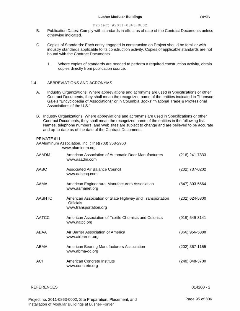
Lusher Modular Buildings
Project #2011-0863-0002
B.
C.
OPSB
Publication Dates: Comply with standards in effect as of date of the Contract Documents unless otherwise indicated.
Copies of Standards: Each entity engaged in construction on Project should be familiar with industry standards applicable to its construction activity. Copies of applicable standards are not bound with the Contract Documents.
1. Where copies of standards are needed to perform a required construction activity, obtain copies directly from publication source.
1.4
A.
ABBREVIATIONS AND ACRONYMS
Industry Organizations: Where abbreviations and acronyms are used in Specifications or other Contract Documents, they shall mean the recognized name of the entities indicated in Thomson Gale's "Encyclopedia of Associations" or in Columbia Books' "National Trade & Professional Associations of the U.S."
Industry Organizations: Where abbreviations and acronyms are used in Specifications or other Contract Documents, they shall mean the recognized name of the entities in the following list. Names, telephone numbers, and Web sites are subject to change and are believed to be accurate and up-to-date as of the date of the Contract Documents. PRIVATE tbl1 AAAluminum Association, Inc. (The)(703) 358-2960 www.aluminum.org
AAADM American Association of Automatic Door Manufacturers www.aaadm.com
Associated Air Balance Council www.aabchq.com
American Engineerural Manufacturers Association www.aamanet.org
American Association of State Highway and Transportation Officials www.transportation.org
American Association of Textile Chemists and Colorists www.aatcc.org
Air Barrier Association of America www.airbarrier.org
American Bearing Manufacturers Association www.abma-dc.org
American Concrete Institute www.concrete.org
(216) 241-7333
B.
AABC (202) 737-0202
AAMA (847) 303-5664
AASHTO (202) 624-5800
AATCC (919) 549-8141
ABAA (866) 956-5888
ABMA (202) 367-1155
ACI (248) 848-3700
REFERENCES 014200 - 2
Project no. 2011-0863-0002, Site Preparation, Placement, and Installation of Modular Buildings at Lusher-Fortier
Page 95 of 306

Lusher Modular Buildings
Project #2011-0863-0002
ACPA
American Concrete Pipe Association www.concrete-pipe.org
Association of Edison Illuminating Companies, Inc. (The) www.aeic.org
American Forest & Paper Association www.afandpa.org
American Gas Association www.aga.org
Associated General Contractors of America (The) www.agc.org
American Hardboard Association (Now part of CPA)
Association of Home Appliance Manufacturers www.aham.org
Asphalt Institute www.asphaltinstitute.org
American Institute of Engineers (The) www.aia.org
American Institute of Steel Construction www.aisc.org
American Iron and Steel Institute www.steel.org
American Institute of Timber Construction www.aitc-glulam.org
Associated Landscape Contractors of America (Now PLANET - Professional Landcare Network)
American Lumber Standard Committee, Incorporated www.alsc.org
Air Movement and Control Association International, Inc. www.amca.org
American National Standards Institute www.ansi.org
Association of Official Seed Analysts, Inc. www.aosaseed.com
OPSB
(972) 506-7216
AEIC (205) 257-2530
AF&PA (800) 878-8878 (202) 463-2700
(202) 824-7000 AGA
AGC (703) 548-3118
AHA
AHAM (202) 872-5955
AI (859) 288-4960
AIA (800) 242-3837 (202) 626-7300
(800) 644-2400 (312) 670-2400
(202) 452-7100
AISC
AISI
AITC (303) 792-9559
ALCA
ALSC (301) 972-1700
AMCA (847) 394-0150
ANSI (202) 293-8020
AOSA (405) 780-7372
REFERENCES 014200 - 3
Project no. 2011-0863-0002, Site Preparation, Placement, and Installation of Modular Buildings at Lusher-Fortier
Page 96 of 306

Lusher Modular Buildings
Project #2011-0863-0002
APA
Engineerural Precast Association www.archprecast.org
APA - The Engineered Wood Association www.apawood.org
APA - The Engineered Wood Association; Engineered Wood Systems (See APA - The Engineered Wood Association)
American Petroleum Institute www.api.org
Air-Conditioning & Refrigeration Institute www.ari.org
Asphalt Roofing Manufacturers Association www.asphaltroofing.org
American Society of Civil Engineers www.asce.org
American Society of Civil Engineers/Structural Engineering Institute (See ASCE)
American Society of Heating, Refrigerating and Air- Conditioning Engineers www.ashrae.org
ASME International (American Society of Mechanical Engineers International) www.asme.org
American Society of Sanitary Engineering www.asse-plumbing.org
ASTM International (American Society for Testing and Materials International) www.astm.org
Association of the Wall and Ceiling Industry www.awci.org
American Window Covering Manufacturers Association (Now WCMA)
Engineerural Woodwork Institute www.awinet.org
American Wood Protection Association
OPSB
(239) 454-6989
APA (253) 565-6600
APA EWS
API (202) 682-8000
ARI (703) 524-8800
ARMA (202) 207-0917
ASCE (800) 548-2723 (703) 295-6300
ASCE/SEI
ASHRAE (800) 527-4723
(404) 636-8400
(800) 843-2763 (973) 882-1170
ASME
ASSE (440) 835-3040
ASTM (610) 832-9500
AWCI (703) 534-8300
AWCMA
AWI (571) 323-3636
AWPA (205) 733-4077
REFERENCES 014200 - 4
Project no. 2011-0863-0002, Site Preparation, Placement, and Installation of Modular Buildings at Lusher-Fortier
Page 97 of 306
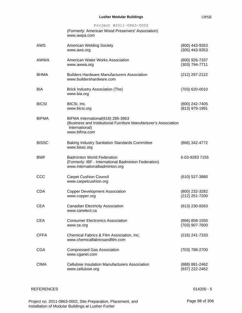
Lusher Modular Buildings
Project #2011-0863-0002
(Formerly: American Wood Preservers' Association) www.awpa.com
OPSB
AWS American Welding Society www.aws.org
American Water Works Association www.awwa.org
Builders Hardware Manufacturers Association www.buildershardware.com
Brick Industry Association (The) www.bia.org
BICSI, Inc. www.bicsi.org
(800) 443-9353 (305) 443-9353
(800) 926-7337 (303) 794-7711
(212) 297-2122
AWWA
BHMA
BIA (703) 620-0010
BICSI (800) 242-7405 (813) 979-1991
BIFMA BIFMA International(616) 285-3963 (Business and Institutional Furniture Manufacturer's Association International) www.bifma.com
Baking Industry Sanitation Standards Committee www.bissc.org
Badminton World Federation (Formerly: IBF - International Badminton Federation) www.internationalbadminton.org
Carpet Cushion Council www.carpetcushion.org
Copper Development Association www.copper.org
Canadian Electricity Association www.canelect.ca
Consumer Electronics Association www.ce.org
Chemical Fabrics & Film Association, Inc. www.chemicalfabricsandfilm.com
Compressed Gas Association www.cganet.com
Cellulose Insulation Manufacturers Association www.cellulose.org
(866) 342-4772BISSC
BWF 6-03-9283 7155
CCC (610) 527-3880
CDA (800) 232-3282 (212) 251-7200
(613) 230-9263 CEA
CEA (866) 858-1555 (703) 907-7600
(216) 241-7333 CFFA
CGA (703) 788-2700
CIMA (888) 881-2462 (937) 222-2462
REFERENCES 014200 - 5
Project no. 2011-0863-0002, Site Preparation, Placement, and Installation of Modular Buildings at Lusher-Fortier
Page 98 of 306
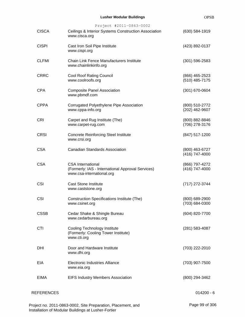
Lusher Modular Buildings
Project #2011-0863-0002
CISCA
Ceilings & Interior Systems Construction Association www.cisca.org
Cast Iron Soil Pipe Institute www.cispi.org
Chain Link Fence Manufacturers Institute www.chainlinkinfo.org
Cool Roof Rating Council www.coolroofs.org
Composite Panel Association www.pbmdf.com
Corrugated Polyethylene Pipe Association www.cppa-info.org
Carpet and Rug Institute (The) www.carpet-rug.com
Concrete Reinforcing Steel Institute www.crsi.org
Canadian Standards Association
OPSB
(630) 584-1919
CISPI (423) 892-0137
CLFMI (301) 596-2583
CRRC (866) 465-2523 (510) 485-7175
(301) 670-0604CPA
CPPA (800) 510-2772 (202) 462-9607
(800) 882-8846 (706) 278-3176
(847) 517-1200
CRI
CRSI
CSA (800) 463-6727 (416) 747-4000
(866) 797-4272 (416) 747-4000
CSA CSA International (Formerly: IAS - International Approval Services) www.csa-international.org
Cast Stone Institute www.caststone.org
Construction Specifications Institute (The) www.csinet.org
Cedar Shake & Shingle Bureau www.cedarbureau.org
Cooling Technology Institute (Formerly: Cooling Tower Institute) www.cti.org
Door and Hardware Institute www.dhi.org
Electronic Industries Alliance www.eia.org
EIFS Industry Members Association
CSI (717) 272-3744
CSI (800) 689-2900 (703) 684-0300
(604) 820-7700 CSSB
CTI (281) 583-4087
DHI (703) 222-2010
EIA (703) 907-7500
EIMA (800) 294-3462
REFERENCES 014200 - 6
Project no. 2011-0863-0002, Site Preparation, Placement, and Installation of Modular Buildings at Lusher-Fortier
Page 99 of 306

Lusher Modular Buildings
Project #2011-0863-0002
www.eima.com
EJCDC
OPSB
(770) 968-7945
(703) 295-5000Engineers Joint Contract Documents Committee www.ejdc.org
Expansion Joint Manufacturers Association, Inc. www.ejma.org
ESD Association (Electrostatic Discharge Association) www.esda.org
Intertek ETL SEMCO (Formerly: ITS - Intertek Testing Service NA) www.intertek.com
Federation Internationale de Basketball (The International Basketball Federation) www.fiba.com
Federation Internationale de Volleyball (The International Volleyball Federation) www.fivb.ch
FM Approvals LLC www.fmglobal.com
FM Global (Formerly: FMG - FM Global) www.fmglobal.com
Factory Mutual Research (Now FM Global)
Florida Roofing, Sheet Metal & Air Conditioning Contractors Association, Inc. www.floridaroof.com
Fluid Sealing Association www.fluidsealing.com
Forest Stewardship Council www.fsc.org
Gypsum Association www.gypsum.org
Glass Association of North America www.glasswebsite.com
(Part of GSI)
EJMA (914) 332-0040
ESD (315) 339-6937
ETL SEMCO (800) 967-5352
FIBA 41 22 545 00 00
FIVB 41 21 345 35 35
FM Approvals (781) 762-4300
FM Global (401) 275-3000
FMRC
FRSA (407) 671-3772
FSA (610) 971-4850
FSC 49 228 367 66 0
GA (202) 289-5440
GANA (785) 271-0208
GRI
REFERENCES 014200 - 7
Project no. 2011-0863-0002, Site Preparation, Placement, and Installation of Modular Buildings at Lusher-Fortier
Page 100 of 306

Lusher Modular Buildings
Project #2011-0863-0002
OPSB
GS Green Seal www.greenseal.org
Geosynthetic Institute www.geosynthetic-institute.org
Hydraulic Institute www.pumps.org
Hydronics Institute www.gamanet.org
Hollow Metal Manufacturers Association (Part of NAAMM)
Hardwood Plywood & Veneer Association www.hpva.org
H. P. White Laboratory, Inc. www.hpwhite.com
International Approval Services (Now CSA International)
International Badminton Federation (Now BWF)
Insulated Cable Engineers Association, Inc. www.icea.net
International Concrete Repair Institute, Inc. www.icri.org
International Electro-technical Commission www.iec.ch
Institute of Electrical and Electronics Engineers, Inc. (The) www.ieee.org
Illuminating Engineering Society of North America www.iesna.org
Institute of Environmental Sciences and Technology www.iest.org
Insulating Glass Certification Council www.igcc.org
Insulating Glass Manufacturers Alliance www.igmaonline.org
(202) 872-6400
GSI (610) 522-8440
HI (973) 267-9700
HI (908) 464-8200
HMMA
HPVA (703) 435-2900
HPW (410) 838-6550
IAS
IBF
ICEA (770) 830-0369
ICRI (847) 827-0830
IEC 41 22 919 02 11
IEEE (212) 419-7900
IESNA (212) 248-5000
IEST (847) 255-1561
IGCC (315) 646-2234
IGMA (613) 233-1510
REFERENCES 014200 - 8
Project no. 2011-0863-0002, Site Preparation, Placement, and Installation of Modular Buildings at Lusher-Fortier
Page 101 of 306

Lusher Modular Buildings
Project #2011-0863-0002
OPSB
ILI Indiana Limestone Institute of America, Inc. www.iliai.com
International Organization for Standardization www.iso.ch
Available from ANSI www.ansi.org
(812) 275-4426
ISO 41 22 749 01 11
(202) 293-8020
ISSFA International Solid Surface Fabricators Association www.issfa.net
Inter-tek Testing Service NA (Now ETL SEMCO)
International Telecommunication Union www.itu.int/home
Kitchen Cabinet Manufacturers Association www.kcma.org
Laminating Materials Association (Now part of CPA)
Lightning Protection Institute www.lightning.org
Metal Building Manufacturers Association www.mbma.com
Maple Flooring Manufacturers Association, Inc. www.maplefloor.org
Metal Framing Manufacturers Association, Inc. www.metalframingmfg.org
Material Handling (Now MHIA)
Material Handling Industry of America www.mhia.org
Marble Institute of America www.marble-institute.com
Master Painters Institute www.paintinfo.com
(877) 464-7732 (702) 567-8150
ITS
ITU 41 22 730 51 11
KCMA (703) 264-1690
LMA
LPI (800) 488-6864
MBMA (216) 241-7333
MFMA (888) 480-9138
MFMA (312) 644-6610
MH
MHIA (800) 345-1815 (704) 676-1190
(440) 250-9222 MIA
MPI (888) 674-8937 (604) 298-7578
MSS Manufacturers Standardization Society of The Valve and Fittings (703) 281-6613 Industry Inc.
REFERENCES 014200 - 9
Project no. 2011-0863-0002, Site Preparation, Placement, and Installation of Modular Buildings at Lusher-Fortier
Page 102 of 306
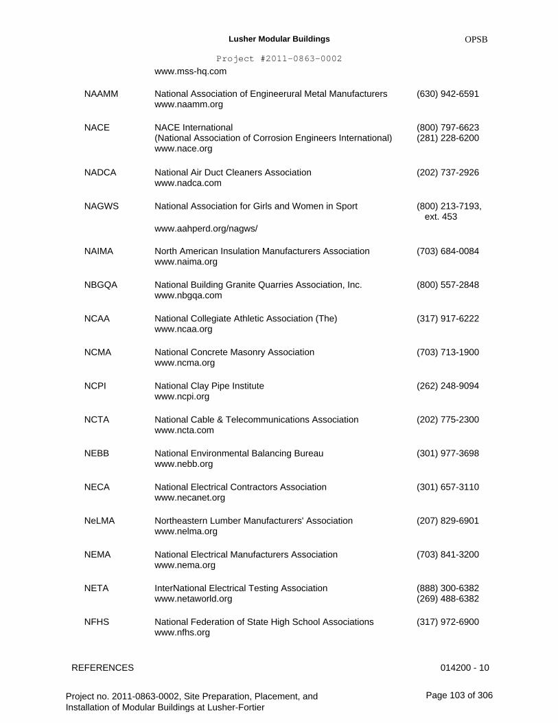
Lusher Modular Buildings
Project #2011-0863-0002
www.mss-hq.com
NAAMM
OPSB
National Association of Engineerural Metal Manufacturers www.naamm.org
NACE International (National Association of Corrosion Engineers International) www.nace.org
National Air Duct Cleaners Association www.nadca.com
National Association for Girls and Women in Sport
www.aahperd.org/nagws/
(630) 942-6591
NACE (800) 797-6623 (281) 228-6200
NADCA (202) 737-2926
NAGWS (800) 213-7193, ext. 453
NAIMA North American Insulation Manufacturers Association www.naima.org
National Building Granite Quarries Association, Inc. www.nbgqa.com
National Collegiate Athletic Association (The) www.ncaa.org
National Concrete Masonry Association www.ncma.org
National Clay Pipe Institute www.ncpi.org
National Cable & Telecommunications Association www.ncta.com
National Environmental Balancing Bureau www.nebb.org
National Electrical Contractors Association www.necanet.org
Northeastern Lumber Manufacturers' Association www.nelma.org
National Electrical Manufacturers Association www.nema.org
InterNational Electrical Testing Association www.netaworld.org
National Federation of State High School Associations www.nfhs.org
(703) 684-0084
NBGQA (800) 557-2848
NCAA (317) 917-6222
NCMA (703) 713-1900
NCPI (262) 248-9094
NCTA (202) 775-2300
NEBB (301) 977-3698
NECA (301) 657-3110
NeLMA (207) 829-6901
NEMA (703) 841-3200
NETA (888) 300-6382 (269) 488-6382
(317) 972-6900 NFHS
REFERENCES 014200 - 10
Project no. 2011-0863-0002, Site Preparation, Placement, and Installation of Modular Buildings at Lusher-Fortier
Page 103 of 306
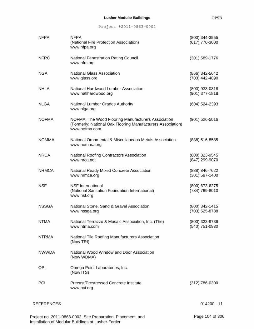
Lusher Modular Buildings
Project #2011-0863-0002
OPSB
NFPA NFPA (National Fire Protection Association) www.nfpa.org
National Fenestration Rating Council www.nfrc.org
National Glass Association www.glass.org
National Hardwood Lumber Association www.natlhardwood.org
National Lumber Grades Authority www.nlga.org
NOFMA: The Wood Flooring Manufacturers Association (Formerly: National Oak Flooring Manufacturers Association) www.nofma.com
National Ornamental & Miscellaneous Metals Association www.nomma.org
National Roofing Contractors Association www.nrca.net
National Ready Mixed Concrete Association www.nrmca.org
NSF International (National Sanitation Foundation International) www.nsf.org
National Stone, Sand & Gravel Association www.nssga.org
National Terrazzo & Mosaic Association, Inc. (The) www.ntma.com
National Tile Roofing Manufacturers Association (Now TRI)
National Wood Window and Door Association (Now WDMA)
Omega Point Laboratories, Inc. (Now ITS)
Precast/Prestressed Concrete Institute www.pci.org
(800) 344-3555 (617) 770-3000
NFRC (301) 589-1776
NGA (866) 342-5642 (703) 442-4890
(800) 933-0318 (901) 377-1818
(604) 524-2393
NHLA
NLGA
NOFMA (901) 526-5016
NOMMA (888) 516-8585
NRCA (800) 323-9545 (847) 299-9070
(888) 846-7622 (301) 587-1400
(800) 673-6275 (734) 769-8010
NRMCA
NSF
NSSGA (800) 342-1415 (703) 525-8788
(800) 323-9736 (540) 751-0930
NTMA
NTRMA
NWWDA
OPL
PCI (312) 786-0300
REFERENCES 014200 - 11
Project no. 2011-0863-0002, Site Preparation, Placement, and Installation of Modular Buildings at Lusher-Fortier
Page 104 of 306
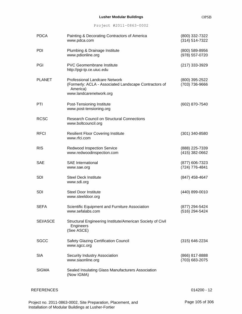
Lusher Modular Buildings
Project #2011-0863-0002
OPSB
PDCA Painting & Decorating Contractors of America www.pdca.com
Plumbing & Drainage Institute www.pdionline.org
PVC Geomembrane Institute http://pgi-tp.ce.uiuc.edu
Professional Landcare Network (Formerly: ACLA - Associated Landscape Contractors of America) www.landcarenetwork.org
Post-Tensioning Institute www.post-tensioning.org
Research Council on Structural Connections www.boltcouncil.org
Resilient Floor Covering Institute www.rfci.com
Redwood Inspection Service www.redwoodinspection.com
SAE International www.sae.org
Steel Deck Institute www.sdi.org
Steel Door Institute www.steeldoor.org
Scientific Equipment and Furniture Association www.sefalabs.com
Structural Engineering Institute/American Society of Civil Engineers (See ASCE)
Safety Glazing Certification Council www.sgcc.org
Security Industry Association www.siaonline.org
Sealed Insulating Glass Manufacturers Association (Now IGMA)
(800) 332-7322 (314) 514-7322
(800) 589-8956 (978) 557-0720
(217) 333-3929
PDI
PGI
PLANET (800) 395-2522 (703) 736-9666
PTI (602) 870-7540
RCSC
RFCI (301) 340-8580
RIS (888) 225-7339 (415) 382-0662
(877) 606-7323 (724) 776-4841
(847) 458-4647
SAE
SDI
SDI (440) 899-0010
SEFA (877) 294-5424 (516) 294-5424
SEI/ASCE
SGCC (315) 646-2234
SIA (866) 817-8888 (703) 683-2075
SIGMA
REFERENCES 014200 - 12
Project no. 2011-0863-0002, Site Preparation, Placement, and Installation of Modular Buildings at Lusher-Fortier
Page 105 of 306

Lusher Modular Buildings
Project #2011-0863-0002
OPSB
SJI Steel Joist Institute www.steeljoist.org
Screen Manufacturers Association www.smacentral.org
Sheet Metal and Air Conditioning Contractors' National Association www.smacna.org
Society of Motion Picture and Television Engineers www.smpte.org
Spray Polyurethane Foam Alliance (Formerly: SPI/SPFD - The Society of the Plastics Industry, Inc.; Spray Polyurethane Foam Division) www.sprayfoam.org
Southern Pine Inspection Bureau (The) www.spib.org
Single Ply Roofing Industry www.spri.org
Specialty Steel Industry of North America www.ssina.com
SSPC: The Society for Protective Coatings www.sspc.org
Steel Tank Institute www.steeltank.com
Steel Window Institute www.steelwindows.com
Sealant, Waterproofing, & Restoration Institute www.swrionline.org
Tile Council of America, Inc. (Now TCNA)
Tile Council of North America, Inc. www.tileusa.com
Telecommunications Industry Association/Electronic Industries Alliance www.tiaonline.org
The Masonry Society
(843) 626-1995
SMA (561) 533-0991
SMACNA (703) 803-2980
SMPTE (914) 761-1100
SPFA (800) 523-6154
SPIB (850) 434-2611
SPRI (781) 647-7026
SSINA (800) 982-0355 (202) 342-8630
(877) 281-7772 (412) 281-2331
(847) 438-8265
SSPC
STI
SWI (216) 241-7333
SWRI (816) 472-7974
TCA
TCNA (864) 646-8453
TIA/EIA (703) 907-7700
TMS (303) 939-9700
REFERENCES 014200 - 13
Project no. 2011-0863-0002, Site Preparation, Placement, and Installation of Modular Buildings at Lusher-Fortier
Page 106 of 306
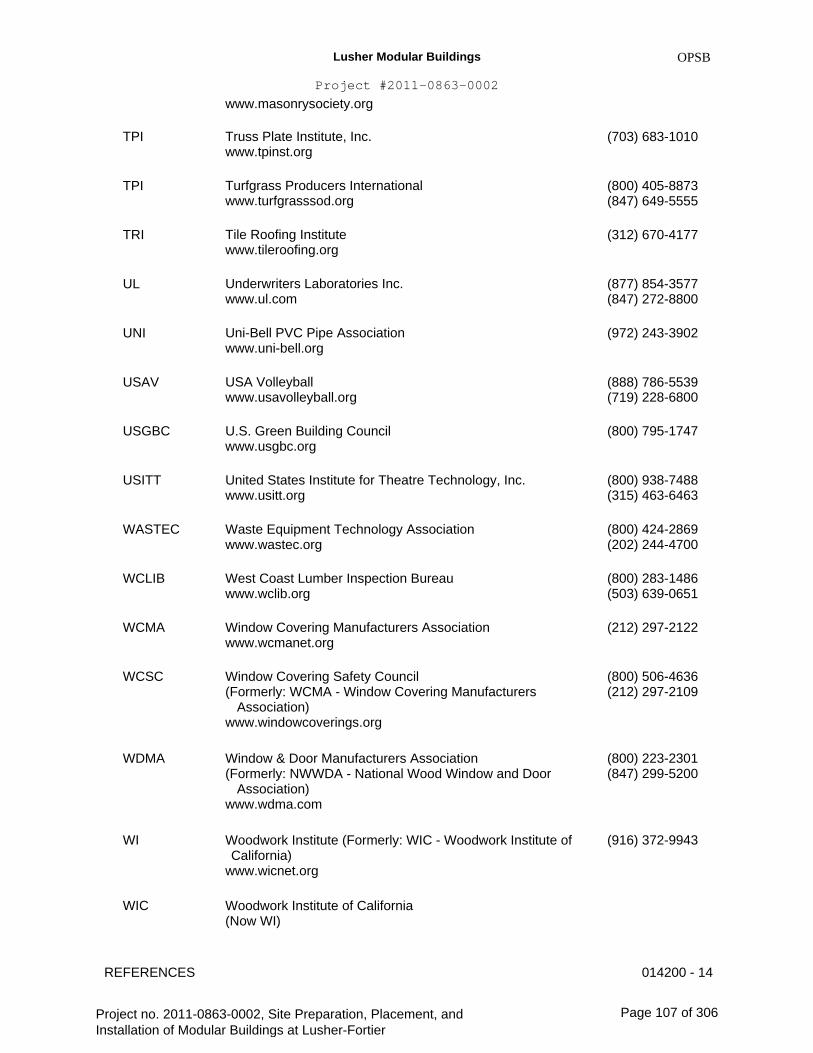
Lusher Modular Buildings
Project #2011-0863-0002
www.masonrysociety.org
OPSB
TPI Truss Plate Institute, Inc. www.tpinst.org
Turfgrass Producers International www.turfgrasssod.org
Tile Roofing Institute www.tileroofing.org
Underwriters Laboratories Inc. www.ul.com
Uni-Bell PVC Pipe Association www.uni-bell.org
USA Volleyball www.usavolleyball.org
U.S. Green Building Council www.usgbc.org
United States Institute for Theatre Technology, Inc. www.usitt.org
Waste Equipment Technology Association www.wastec.org
West Coast Lumber Inspection Bureau www.wclib.org
Window Covering Manufacturers Association www.wcmanet.org
Window Covering Safety Council (Formerly: WCMA - Window Covering Manufacturers Association) www.windowcoverings.org
Window & Door Manufacturers Association (Formerly: NWWDA - National Wood Window and Door Association) www.wdma.com
Woodwork Institute (Formerly: WIC - Woodwork Institute of California) www.wicnet.org
Woodwork Institute of California (Now WI)
(703) 683-1010
TPI (800) 405-8873 (847) 649-5555
(312) 670-4177TRI
UL (877) 854-3577 (847) 272-8800
(972) 243-3902 UNI
USAV (888) 786-5539 (719) 228-6800
(800) 795-1747USGBC
USITT (800) 938-7488 (315) 463-6463
(800) 424-2869 (202) 244-4700
(800) 283-1486 (503) 639-0651
(212) 297-2122
WASTEC
WCLIB
WCMA
WCSC (800) 506-4636 (212) 297-2109
WDMA (800) 223-2301 (847) 299-5200
WI (916) 372-9943
WIC
REFERENCES 014200 - 14
Project no. 2011-0863-0002, Site Preparation, Placement, and Installation of Modular Buildings at Lusher-Fortier
Page 107 of 306

Lusher Modular Buildings
Project #2011-0863-0002
OPSB
WMMPA Wood Moulding & Millwork Producers Association www.wmmpa.com
Western States Roofing Contractors Association www.wsrca.com
Western Wood Products Association www.wwpa.org
(800) 550-7889 (530) 661-9591
(800) 725-0333 (650) 570-5441
(503) 224-3930
WSRCA
WWPA
C. Code Agencies: Where abbreviations and acronyms are used in Specifications or other Contract Documents, they shall mean the recognized name of the entities in the following list. Names, telephone numbers, and Web sites are subject to change and are believed to be accurate and up- to-date as of the date of the Contract Documents. PRIVATE tbl2 IAPMO International Association of Plumbing and Mechanical Officials(909) 472-4100 www.iapmo.org
ICC International Code Council www.iccsafe.org
ICC Evaluation Service, Inc. www.icc-es.org
Uniform Building Code (See ICC)
(888) 422-7233
ICC-ES (800) 423-6587 (562) 699-0543
UBC
D. Federal Government Agencies: Where abbreviations and acronyms are used in Specifications or other Contract Documents, they shall mean the recognized name of the entities in the following list. Names, telephone numbers, and Web sites are subject to change and are believed to be accurate and up-to-date as of the date of the Contract Documents. PRIVATE tbl3 CEArmy Corps of Engineers(202) 761-0011 www.usace.army.mil
CPSC Consumer Product Safety Commission www.cpsc.gov
Department of Commerce www.commerce.gov
Department of Defense http://.dodssp.daps.dla.mil
Department of Energy www.energy.gov
Environmental Protection Agency www.epa.gov
Federal Aviation Administration
(800) 638-2772 (301) 504-7923
(202) 482-2000 DOC
DOD (215) 697-6257
DOE (202) 586-9220
EPA (202) 272-0167
FAA (866) 835-5322
REFERENCES 014200 - 15
Project no. 2011-0863-0002, Site Preparation, Placement, and Installation of Modular Buildings at Lusher-Fortier
Page 108 of 306
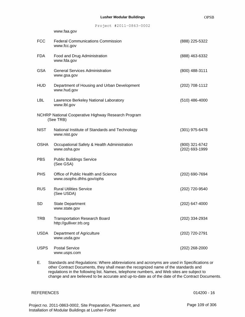
Lusher Modular Buildings
Project #2011-0863-0002
www.faa.gov
FCC
OPSB
Federal Communications Commission www.fcc.gov
Food and Drug Administration www.fda.gov
General Services Administration www.gsa.gov
Department of Housing and Urban Development www.hud.gov
Lawrence Berkeley National Laboratory www.lbl.gov
(888) 225-5322
FDA (888) 463-6332
GSA (800) 488-3111
HUD (202) 708-1112
LBL (510) 486-4000
NCHRP National Cooperative Highway Research Program (See TRB)
NIST National Institute of Standards and Technology www.nist.gov
Occupational Safety & Health Administration www.osha.gov
Public Buildings Service (See GSA)
Office of Public Health and Science www.osophs.dhhs.gov/ophs
Rural Utilities Service (See USDA)
State Department www.state.gov
Transportation Research Board http://gulliver.trb.org
Department of Agriculture www.usda.gov
Postal Service www.usps.com
(202) 690-7694
(301) 975-6478
OSHA (800) 321-6742 (202) 693-1999
PBS
PHS
RUS (202) 720-9540
SD (202) 647-4000
TRB (202) 334-2934
USDA (202) 720-2791
USPS
E.
(202) 268-2000
Standards and Regulations: Where abbreviations and acronyms are used in Specifications or other Contract Documents, they shall mean the recognized name of the standards and regulations in the following list. Names, telephone numbers, and Web sites are subject to change and are believed to be accurate and up-to-date as of the date of the Contract Documents.
REFERENCES 014200 - 16
Project no. 2011-0863-0002, Site Preparation, Placement, and Installation of Modular Buildings at Lusher-Fortier
Page 109 of 306

Lusher Modular Buildings
Project #2011-0863-0002
OPSB
PRIVATE tbl4 ADAAG Americans with Disabilities Act (ADA)
Engineerural Barriers Act (ABA)
Accessibility Guidelines for Buildings and Facilities Available from U.S. Access Board www.access-board.gov
CFR Code of Federal Regulations
Available from Government Printing Office
www.gpoaccess.gov/cfr/index.html
DOD Department of Defense Military Specifications and Standards
Available from Department of Defense Single Stock Point http://dodssp.daps.dla.mil
DSCC Defense Supply Center Columbus (See FS)
Federal Standard (See FS)
Federal Specification
Available from Department of Defense Single Stock Point http://dodssp.daps.dla.mil
Available from Defense Standardization Program www.dps.dla.mil
Available from General Services Administration
www.gsa.gov
Available from National Institute of Building Sciences
www.wbdg.org/ccb
FTMS Federal Test Method Standard (See FS)
(See MILSPEC)
(See MILSPEC)
Military Specification and Standards
(800) 872- 2253 (202) 272- 0080
(866) 512- 1800 (202) 512- 1800
(215) 697- 2664
FED-STD
FS (215) 697- 2664
(202) 619- 8925
(202) 289- 7800
MIL
MIL-STD
MILSPEC (215) 697- 2664
REFERENCES 014200 - 17
Project no. 2011-0863-0002, Site Preparation, Placement, and Installation of Modular Buildings at Lusher-Fortier
Page 110 of 306
Lusher Modular Buildings
Project #2011-0863-0002
OPSB
Available from Department of Defense Single Stock Point http://dodssp.daps.dla.mil
UFAS Uniform Federal Accessibility Standards
Available from Access Board
www.access-board.gov
F. State Government Agencies: Where abbreviations and acronyms are used in Specifications or other Contract Documents, they shall mean the recognized name of the entities in the following list. Names, telephone numbers, and Web sites are subject to change and are believed to be accurate and up-to-date as of the date of the Contract Documents. PRIVATE tbl5 CBHF State of California, Department of Consumer Affairs Bureau of Home(800) 952- Furnishings and Thermal Insulation5210 www.dca.ca.gov/bhfti(916) 574- 2041
CCR California Code of Regulations
www.calregs.com
CPUC California Public Utilities Commission
www.cpuc.ca.gov
TFS Texas Forest Service
Forest Resource Development http://txforestservice.tamu.edu
PART 2 - PRODUCTS (Not Used)
PART 3 - EXECUTION (Not Used)
END OF SECTION 014200
(979) 458- 6650
(415) 703- 2782
(916) 323- 6815
(800) 872- 2253 (202) 272- 0080
REFERENCES 014200 - 18
Project no. 2011-0863-0002, Site Preparation, Placement, and Installation of Modular Buildings at Lusher-Fortier
Page 111 of 306

Lusher Modular Buildings
Project #2011-0863-0002
OPSB
SECTION 015000 - TEMPORARY FACILITIES AND CONTROLS
PART 1 - GENERAL
1.1
A.
RELATED DOCUMENTS
Drawings and general provisions of the Contract, including General and Supplementary Conditions and other Division 01 Specification Sections, apply to this Section.
SUMMARY
A.
B.
Section includes requirements for temporary utilities, support facilities, and security and protection facilities.
Related Requirements:
1.
2. 3.
4.
Division 01 Section "Summary" for work restrictions and limitations on utility interruptions. Division 31 Section "Dewatering" for disposal of ground water at Project site. Division 32 Section "Asphalt Paving" for construction and maintenance of asphalt pavement for temporary roads and paved areas. Division 32 Section "Concrete Paving" for construction and maintenance of cement concrete pavement for temporary roads and paved areas.
1.2
1.3
A.
USE CHARGES
General: Installation and removal of and use charges for temporary facilities shall be included in the Contract Sum unless otherwise indicated. Allow other entities to use temporary services and facilities without cost, including, but not limited to Engineer, testing agencies, and authorities having jurisdiction.
Sewer Service: Pay sewer-service use charges for sewer usage by all entities for construction operations.
Water Service: Pay water-service use charges for water used by all entities for construction operations.
Electric Power Service: Pay electric-power-service use charges for electricity used by all entities for construction operations.
INFORMATIONAL SUBMITTALS
A. Site Plan: Show temporary facilities, utility hookups, staging areas, and parking areas for construction personnel.
B.
C.
D.
1.4
TEMPORARY FACILITIES AND CONTROLS 015000 - 1
Project no. 2011-0863-0002, Site Preparation, Placement, and Installation of Modular Buildings at Lusher-Fortier
Page 112 of 306
Lusher Modular Buildings
Project #2011-0863-0002
B.
C.
OPSB
Erosion- and Sedimentation-Control Plan: Show compliance with requirements of EPA Construction General Permit or authorities having jurisdiction, whichever is more stringent.
Fire-Safety Program: Show compliance with requirements of NFPA 241 and authorities having jurisdiction. Indicate Contractor personnel responsible for management of fire-prevention program.
Moisture-Protection Plan: Describe procedures and controls for protecting materials and construction from water absorption and damage.
1.
2.
3.
Describe delivery, handling, and storage provisions for materials subject to water absorption or water damage. Indicate procedures for discarding water-damaged materials, protocols for mitigating water intrusion into completed Work, and replacing water-damaged Work. Indicate sequencing of work that requires water, such as sprayed fire-resistive materials, plastering, and terrazzo grinding, and describe plans for dealing with water from these operations. Show procedures for verifying that wet construction has dried sufficiently to permit installation of finish materials.
D.
E. Dust- and HVAC-Control Plan: Submit coordination drawing and narrative that indicates the dust- and HVAC-control measures proposed for use, proposed locations, and proposed time frame for their operation. Identify further options if proposed measures are later determined to be inadequate. Include the following:
1. 2. 3.
Locations of dust-control partitions at each phase of work. Waste handling procedures. Other dust-control measures.
1.5
A.
B.
QUALITY ASSURANCE
Electric Service: Comply with NECA, NEMA, and UL standards and regulations for temporary electric service. Install service to comply with NFPA 70.
Tests and Inspections: Arrange for authorities having jurisdiction to test and inspect each temporary utility before use. Obtain required certifications and permits.
PART 2 - PRODUCTS
2.1
A.
MATERIALS
Chain-Link Fencing: Minimum 2-inch, 0.148-inch thick, galvanized-steel, chain-link fabric fencing; minimum 10 feet high with galvanized-steel pipe posts; minimum 2-3/8-inch- OD line posts and 2-7/8-inch- OD corner and pull posts, with 1-5/8-inch- OD top rails or match existing fence, including gates.
TEMPORARY FACILITIES AND CONTROLS 015000 - 2
Project no. 2011-0863-0002, Site Preparation, Placement, and Installation of Modular Buildings at Lusher-Fortier
Page 113 of 306

Lusher Modular Buildings
Project #2011-0863-0002
PART 3 - EXECUTION
3.1
A.
OPSB
INSTALLATION, GENERAL
Locate facilities where they will serve Project adequately and result in minimum interference with performance of the Work. Relocate and modify facilities as required by progress of the Work.
1.
B.
C.
Locate facilities to limit site disturbance as specified in Division 01 Section "Summary."
Provide each facility ready for use when needed to avoid delay. Do not remove until facilities are no longer needed or are replaced by authorized use of completed permanent facilities.
Temporary Roads and Paved Areas: Construct and maintain temporary roads and paved areas adequate for construction operations. Locate temporary roads and paved areas within construction limits indicated on Drawings.
1. Provide dust-control treatment that is nonpolluting and non-tracking. Reapply treatment as required to minimize dust.
D. Temporary Use of Permanent Roads and Paved Areas: Locate temporary roads and paved areas in same location as permanent roads and paved areas. Construct and maintain temporary roads and paved areas adequate for construction operations. Extend temporary roads and paved areas, within construction limits indicated, as necessary for construction operations.
1.
2.
3.
4.
Coordinate elevations of temporary roads and paved areas with permanent roads and paved areas. Prepare subgrade and install sub-base and base for temporary roads and paved areas according to Division 31 Section "Earth Moving." Recondition base after temporary use, including removing contaminated material, Re-grading, proof-rolling, compacting, and testing. Delay installation of final course of permanent hot-mix asphalt pavement until immediately before Substantial Completion. Repair hot-mix asphalt base-course pavement before installation of final course according to Division 32 Section "Asphalt Paving."
E. Traffic Controls: Comply with requirements of authorities having jurisdiction.
1. 2.
Protect existing site improvements to remain including curbs, pavement, and utilities. Maintain access for fire-fighting equipment and access to fire hydrants.
F.
G.
Parking: Use designated areas of Owner's existing parking areas for construction personnel.
Dewatering Facilities and Drains: Comply with requirements of authorities having jurisdiction. Maintain Project site, excavations, and construction free of water.
1. Dispose of rainwater in a lawful manner that will not result in flooding Project or adjoining properties or endanger permanent Work or temporary facilities.
TEMPORARY FACILITIES AND CONTROLS 015000 - 3
Project no. 2011-0863-0002, Site Preparation, Placement, and Installation of Modular Buildings at Lusher-Fortier
Page 114 of 306

Lusher Modular Buildings
Project #2011-0863-0002
H.
OPSB
Waste Disposal Facilities: Comply with requirements specified in Division 01 Section "Construction Waste Management and Disposal."
SECURITY AND PROTECTION FACILITIES INSTALLATION3.2
A. Protection of Existing Facilities: Protect existing vegetation, equipment, structures, utilities, and other improvements at Project site and on adjacent properties, except those indicated to be removed or altered. Repair damage to existing facilities.
Environmental Protection: Provide protection, operate temporary facilities, and conduct construction as required to comply with environmental regulations and that minimize possible air, waterway, and subsoil contamination or pollution or other undesirable effects.
1. Comply with work restrictions specified in Division 01 Section "Summary."
B.
C. Temporary Erosion and Sedimentation Control: Provide measures to prevent soil erosion and discharge of soil-bearing water runoff and airborne dust to undisturbed areas and to adjacent properties and walkways, according to requirements of the erosion control details and 2003 EPA Construction General Permit or authorities having jurisdiction, whichever is more stringent.
1.
2.
3.
4.
Verify that flows of water redirected from construction areas or generated by construction activity do not enter or cross tree- or plant- protection zones. Inspect, repair, and maintain erosion- and sedimentation-control measures during construction until permanent vegetation has been established. Clean, repair, and restore adjoining properties and roads affected by erosion and sedimentation from Project site during the course of Project. Remove erosion and sedimentation controls and restore and stabilize areas disturbed during removal.
D. Storm water Control: Comply with requirements of authorities having jurisdiction. Provide barriers in and around excavations and subgrade construction to prevent flooding by runoff of storm water from heavy rains.
Tree and Plant Protection: Install temporary fencing located as indicated or outside the drip line of trees to protect vegetation from damage from construction operations. Protect tree root systems from damage, flooding, and erosion.
Pest Control: Engage pest-control service to recommend practices to minimize attraction and harboring of rodents, roaches, and other pests and to perform extermination and control procedures at regular intervals so Project will be free of pests and their residues at Substantial Completion. Perform control operations lawfully, using environmentally safe materials.
Security Enclosure and Lockup: Install temporary enclosure around partially completed areas of construction. Provide lockable entrances to prevent unauthorized entrance, vandalism, theft, and similar violations of security. Lock entrances at end of each work day.
Barricades, Warning Signs, and Lights: Comply with requirements of authorities having jurisdiction for erecting structurally adequate barricades, including warning signs and lighting.
E.
F.
G.
H.
TEMPORARY FACILITIES AND CONTROLS 015000 - 4
Project no. 2011-0863-0002, Site Preparation, Placement, and Installation of Modular Buildings at Lusher-Fortier
Page 115 of 306
Lusher Modular Buildings
Project #2011-0863-0002
I.
OPSB
Temporary Egress: Maintain temporary egress from existing occupied facilities as indicated and as required by authorities having jurisdiction.
MOISTURE AND MOLD CONTROL3.3
A.
B.
Contractor's Moisture-Protection Plan: Avoid trapping water in finished work. Document visible signs of mold that may appear during construction.
Exposed Construction Phase: Before installation of weather barriers, when materials are subject to wetting and exposure and to airborne mold spores, protect as follows:
1. 2. 3. 4. 5.
Protect porous materials from water damage. Protect stored and installed material from flowing or standing water. Keep porous and organic materials from coming into prolonged contact with concrete. Remove standing water from decks. Keep deck openings covered or dammed.
3.4
A.
B.
C.
D.
OPERATION, TERMINATION, AND REMOVAL
Supervision: Enforce strict discipline in use of temporary facilities. To minimize waste and abuse, limit availability of temporary facilities to essential and intended uses.
Maintenance: Maintain facilities in good operating condition until removal.
Temporary Facility Changeover: Do not change over from using temporary security and protection facilities to permanent facilities until Substantial Completion.
Termination and Removal: Remove each temporary facility when need for its service has ended, when it has been replaced by authorized use of a permanent facility, or no later than Substantial Completion. Complete or, if necessary, restore permanent construction that may have been delayed because of interference with temporary facility. Repair damaged Work, clean exposed surfaces, and replace construction that cannot be satisfactorily repaired.
1.
2.
Materials and facilities that constitute temporary facilities are property of Contractor. Owner reserves right to take possession of Project identification signs. Remove temporary roads and paved areas not intended for or acceptable for integration into permanent construction. Where area is intended for landscape development, remove soil and aggregate fill that do not comply with requirements for fill or subsoil. Remove materials contaminated with road oil, asphalt and other petrochemical compounds, and other substances that might impair growth of plant materials or lawns. Repair or replace street paving, curbs, and sidewalks at temporary entrances, as required by authorities having jurisdiction. At Substantial Completion, repair, renovate, and clean permanent facilities used during construction period. Comply with final cleaning requirements specified in Division 01 Section "Closeout Procedures."
3.
END OF SECTION 015000
TEMPORARY FACILITIES AND CONTROLS 015000 - 5
Project no. 2011-0863-0002, Site Preparation, Placement, and Installation of Modular Buildings at Lusher-Fortier
Page 116 of 306
Lusher Modular Buildings
Project #2011-0863-0002
OPSB
SECTION 017300 - EXECUTION
PART 1 - GENERAL
1.1
A.
RELATED DOCUMENTS
Drawings and general provisions of the Contract, including General and Supplementary Conditions and other Division 01 Specification Sections, apply to this Section.
SUMMARY
A. Section includes general administrative and procedural requirements governing execution of the Work including, but not limited to, the following:
1. 2. 3. 4. 5. 6. 7. 8.
B.
Construction layout. Field engineering. Installation of the Work. Cutting and patching. Progress cleaning. Starting and adjusting. Protection of installed construction. Correction of the Work.
1.2
Related Requirements:
1. 2.
Division 01 Section "Summary" for limits on use of Project site. Division 01 Section "Closeout Procedures" for submitting final property survey with Project Record Documents, recording of Owner-accepted deviations from indicated lines and levels, and final cleaning.
1.3
A.
B.
DEFINITIONS
Cutting: Removal of in-place construction necessary to permit installation or performance of other work.
Patching: Fitting and repair work required to restore construction to original conditions after installation of other work.
INFORMATIONAL SUBMITTALS
A.
B.
Qualification Data: For professional engineer.
Certificates: Submit certificate signed by professional engineer certifying that location and elevation of improvements comply with requirements.
1.4
EXECUTION 017300 - 1
Project no. 2011-0863-0002, Site Preparation, Placement, and Installation of Modular Buildings at Lusher-Fortier
Page 117 of 306

Lusher Modular Buildings
Project #2011-0863-0002
C.
OPSB
Cutting and Patching Plan: Submit plan describing procedures at least 5 days prior to the time cutting and patching will be performed. Include the following information:
1. 2.
3.
Extent: Describe reason for and extent of each occurrence of cutting and patching. Products: List products to be used for patching and entities that will perform patching work. Dates: Indicate when cutting and patching will be performed.
D. Landfill Receipts: Submit copy of receipts issued by a landfill facility, licensed to accept hazardous materials, for hazardous waste disposal.
QUALITY ASSURANCE 1.5
A.
B.
Cutting and Patching: Comply with requirements for and limitations on cutting and patching of construction elements.
Cutting and Patching Conference: Before proceeding, meet at Project site with parties involved in cutting and patching. Review areas of potential interference and conflict. Coordinate procedures and resolve potential conflicts before proceeding.
PART 2 - PRODUCTS
2.1
A.
MATERIALS
General: Comply with requirements specified in other Sections.
1.
B.
For projects requiring compliance with sustainable design and construction practices and procedures.
In-Place Materials: Use materials for patching identical to in-place materials. For exposed surfaces, use materials that visually match in-place adjacent surfaces to the fullest extent possible.
1. If identical materials are unavailable or cannot be used, use materials that, when installed, will provide a match acceptable to Engineer for the visual and functional performance of in-place materials.
PART 3 - EXECUTION
3.1
A.
EXAMINATION
Existing Conditions: The existence and location of underground and other utilities and construction indicated as existing are not guaranteed. Before beginning sitework, investigate and verify the existence and location of underground utilities, including electrical systems, and other construction affecting the Work.
EXECUTION 017300 - 2
Project no. 2011-0863-0002, Site Preparation, Placement, and Installation of Modular Buildings at Lusher-Fortier
Page 118 of 306

Lusher Modular Buildings
Project #2011-0863-0002
1.
OPSB
2.
B.
Before construction, verify the location and invert elevation at points of connection of sanitary sewer, storm sewer, and water-service piping; underground electrical services, and other utilities. Furnish location data for work related to Project that must be performed by public utilities serving Project site.
Examination and Acceptance of Conditions: Before proceeding with each component of the Work, examine substrates, areas, and conditions, with Installer or Applicator present where indicated, for compliance with requirements for installation tolerances and other conditions affecting performance. Record observations.
1.
2.
3.
Examine roughing-in for mechanical and electrical systems to verify actual locations of connections before equipment and fixture installation. Examine walls, floors, and roofs for suitable conditions where products and systems are to be installed. Verify compatibility with and suitability of substrates, including compatibility with existing finishes or primers.
C. Written Report: Where a written report listing conditions detrimental to performance of the Work is required by other Sections, include the following:
1. 2. 3. 4.
Description of the Work. List of detrimental conditions, including substrates. List of unacceptable installation tolerances. Recommended corrections.
D. Proceed with installation only after unsatisfactory conditions have been corrected. Proceeding with the Work indicates acceptance of surfaces and conditions.
PREPARATION 3.2
A. Existing Utility Information: Furnish information to local utility& Owner that is necessary to adjust, move, or relocate existing utility structures, utility poles, lines, services, or other utility appurtenances located in or affected by construction. Coordinate with authorities having jurisdiction.
Field Measurements: Take field measurements as required to fit the Work properly. Recheck measurements before installing each product. Where portions of the Work are indicated to fit to other construction, verify dimensions of other construction by field measurements before fabrication. Coordinate fabrication schedule with construction progress to avoid delaying the Work.
Review of Contract Documents and Field Conditions: Immediately on discovery of the need for clarification of the Contract Documents caused by differing field conditions outside the control of Contractor, submit a request for information to Engineer according to requirements in Division 01 Section "Project Management and Coordination."
B.
C.
EXECUTION 017300 - 3
Project no. 2011-0863-0002, Site Preparation, Placement, and Installation of Modular Buildings at Lusher-Fortier
Page 119 of 306
Lusher Modular Buildings
Project #2011-0863-0002
3.3
A.
CONSTRUCTION LAYOUT
OPSB
Verification: Before proceeding to lay out the Work, verify layout information shown on Drawings, in relation to the property survey and existing benchmarks. If discrepancies are discovered, notify Engineer and Construction Manager promptly.
General: Engage a licensed professional engineer to lay out the Work using accepted surveying practices.
1.
2. 3.
4. 5. 6.
7.
Establish benchmarks and control points to set lines and levels at each story of construction and elsewhere as needed to locate each element of Project. Establish limits on use of Project site. Establish dimensions within tolerances indicated. Do not scale Drawings to obtain required dimensions. Inform installers of lines and levels to which they must comply. Check the location, level and plumb, of every major element as the Work progresses. Notify Engineer and Construction Manager when deviations from required lines and levels exceed allowable tolerances. Close site surveys with an error of closure equal to or less than the standard established by authorities having jurisdiction.
B.
C.
D.
Site Improvements: Locate and lay out site improvements, including pavements, grading, fill and topsoil placement, utility slopes, and rim and invert elevations.
Building Lines and Levels: Locate and lay out control lines and levels for structures, building foundations, column grids, and floor levels, including those required for mechanical and electrical work. Transfer survey markings and elevations for use with control lines and levels. Level foundations and piers from two or more locations.
Record Log: Maintain a log of layout control work. Record deviations from required lines and levels. Include beginning and ending dates and times of surveys, weather conditions, name and duty of each survey party member, and types of instruments and tapes used. Make the log available for reference by Engineer and Construction Manager.
FIELD ENGINEERING
E.
3.4
A.
B.
Identification: Owner will identify existing benchmarks, control points, and property corners.
Reference Points: Locate existing permanent benchmarks, control points, and similar reference points before beginning the Work. Preserve and protect permanent benchmarks and control points during construction operations.
1. Do not change or relocate existing benchmarks or control points without prior written approval of Engineer or Construction Manager. Report lost or destroyed permanent benchmarks or control points promptly. Report the need to relocate permanent benchmarks or control points to Engineer and Construction Manager before proceeding. Replace lost or destroyed permanent benchmarks and control points promptly. Base replacements on the original survey control points.
2.
EXECUTION 017300 - 4
Project no. 2011-0863-0002, Site Preparation, Placement, and Installation of Modular Buildings at Lusher-Fortier
Page 120 of 306
Lusher Modular Buildings
Project #2011-0863-0002
C.
OPSB
Benchmarks: Establish and maintain a minimum of two permanent benchmarks on Project site, referenced to data established by survey control points. Comply with authorities having jurisdiction for type and size of benchmark.
1.
2.
3.
Record benchmark locations, with horizontal and vertical data, on Project Record Documents. Where the actual location or elevation of layout points cannot be marked, provide temporary reference points sufficient to locate the Work. Remove temporary reference points when no longer needed. Restore marked construction to its original condition.
D. Certified Survey: On completion of foundation walls, major site improvements, and other work requiring field-engineering services, prepare a certified survey showing dimensions, locations, angles, and elevations of construction and sitework.
INSTALLATION 3.5
A. General: Locate the Work and components of the Work accurately, in correct alignment and elevation, as indicated.
1. 2.
3.
Make vertical work plumb and make horizontal work level. Where space is limited, install components to maximize space available for maintenance and ease of removal for replacement. Conceal pipes, ducts, and wiring in finished areas unless otherwise indicated.
B.
C.
D.
E.
F.
G.
Comply with manufacturer's written instructions and recommendations for installing products in applications indicated.
Install products at the time and under conditions that will ensure the best possible results. Maintain conditions required for product performance until Substantial Completion.
Conduct construction operations so no part of the Work is subjected to damaging operations or loading in excess of that expected during normal conditions of occupancy.
Sequence the Work and allow adequate clearances to accommodate movement of construction items on site and placement in permanent locations.
Tools and Equipment: Do not use tools or equipment that produce harmful noise levels.
Templates: Obtain and distribute to the parties involved templates for work specified to be factory prepared and field installed. Check Shop Drawings of other work to confirm that adequate provisions are made for locating and installing products to comply with indicated requirements.
Attachment: Provide blocking and attachment plates and anchors and fasteners of adequate size and number to securely anchor each component in place, accurately located and aligned with other portions of the Work. Where size and type of attachments are not indicated, verify size and type required for load conditions.
H.
EXECUTION 017300 - 5
Project no. 2011-0863-0002, Site Preparation, Placement, and Installation of Modular Buildings at Lusher-Fortier
Page 121 of 306
Lusher Modular Buildings
Project #2011-0863-0002
1.
2. 3.
OPSB
Mounting Heights: Where mounting heights are not indicated, mount components at heights directed by Engineer. Allow for building movement, including thermal expansion and contraction. Coordinate installation of anchorages. Furnish setting drawings, templates, and directions for installing anchorages, including sleeves, concrete inserts, anchor bolts, and items with integral anchors, that are to be embedded in concrete or masonry. Deliver such items to Project site in time for installation.
3.6
A.
B.
OWNER-INSTALLED PRODUCTS
Site Access: Provide access to Project site for Owner's construction personnel.
Coordination: Coordinate construction and operations of the Work with work performed by Owner's construction personnel.
1. Construction Schedule: Inform Owner of Contractor's preferred construction schedule for Owner's portion of the Work. Adjust construction schedule based on a mutually agreeable timetable. Notify Owner if changes to schedule are required due to differences in actual construction progress. Preinstallation Conferences: Include Owner's construction personnel at pre-installation conferences covering portions of the Work that are to receive Owner's work. Attend pre-installation conferences conducted by Owner's construction personnel if portions of the Work depend on Owner's construction.
2.
3.7
A.
PROGRESS CLEANING
General: Clean Project site and work areas daily, including common areas. requirements strictly. Dispose of materials lawfully.
1.
2.
3.
Enforce
Comply with requirements in NFPA 241 for removal of combustible waste materials and debris. Do not hold waste materials more than seven days during normal weather or three days if the temperature is expected to rise above 80 deg F. Containerize hazardous and unsanitary waste materials separately from other waste. Mark containers appropriately and dispose of legally, according to regulations.
a. Use containers intended for holding waste materials of type to be stored.
4.
B.
C.
Coordinate progress cleaning for joint-use areas where Contractor and other contractors are working concurrently.
Site: Maintain Project site free of waste materials and debris.
Work Areas: Clean areas where work is in progress to the level of cleanliness necessary for proper execution of the Work.
1. 2.
Remove liquid spills promptly. Where dust would impair proper execution of the Work, broom-clean or vacuum the entire work area, as appropriate.
EXECUTION 017300 - 6
Project no. 2011-0863-0002, Site Preparation, Placement, and Installation of Modular Buildings at Lusher-Fortier
Page 122 of 306

Lusher Modular Buildings
Project #2011-0863-0002
D.
OPSB
Installed Work: Keep installed work clean. Clean installed surfaces according to written instructions of manufacturer or fabricator of product installed, using only cleaning materials specifically recommended. If specific cleaning materials are not recommended, use cleaning materials that are not hazardous to health or property and that will not damage exposed surfaces.
Concealed Spaces: Remove debris from concealed spaces before enclosing the space.
Exposed Surfaces in Finished Areas: Clean exposed surfaces and protect as necessary to ensure freedom from damage and deterioration at time of Substantial Completion.
Waste Disposal: Do not bury or burn waste materials on-site. Do not wash waste materials down sewers or into waterways. Comply with waste disposal requirements in Division 01 Section "Construction Waste Management and Disposal."
During handling and installation, clean and protect construction in progress and adjoining materials already in place. Apply protective covering where required to ensure protection from damage or deterioration at Substantial Completion.
Clean and provide maintenance on completed construction as frequently as necessary through the remainder of the construction period. Adjust and lubricate operable components to ensure operability without damaging effects.
Limiting Exposures: Supervise construction operations to assure that no part of the construction, completed or in progress, is subject to harmful, dangerous, damaging, or otherwise deleterious exposure during the construction period.
STARTING AND ADJUSTING
E.
F.
G.
H.
I.
J.
3.8
A.
B.
C.
D.
Start equipment and operating components to confirm proper operation. malfunctioning units, replace with new units, and retest.
Remove
Adjust equipment for proper operation. Adjust operating components for proper operation without binding.
Test each piece of equipment to verify proper operation. Test and adjust controls and safeties. Replace damaged and malfunctioning controls and equipment.
Manufacturer's Field Service: Comply with qualification requirements in Division 01 Section "Quality Requirements."
PROTECTION OF INSTALLED CONSTRUCTION 3.9
A.
B.
Provide final protection and maintain conditions that ensure installed Work is without damage or deterioration at time of Substantial Completion.
Comply with manufacturer's written instructions for temperature and relative humidity.
END OF SECTION 017300
EXECUTION 017300 - 7
Project no. 2011-0863-0002, Site Preparation, Placement, and Installation of Modular Buildings at Lusher-Fortier
Page 123 of 306
Lusher Modular Buildings
Project #2011-0863-0002
OPSB
SECTION 017419 - CONSTRUCTION WASTE MANAGEMENT AND DISPOSAL
PART 1 - GENERAL
1.1
A.
RELATED DOCUMENTS
Drawings and general provisions of the Contract, including General and Supplementary Conditions and other Division 01 Specification Sections, apply to this Section.
SUMMARY
A.
B.
Section includes administrative and procedural requirements for the following: 1.Disposing of nonhazardous demolition and construction waste.
Related Requirements: 1.Division 31 Section "Site Clearing" for disposition of waste resulting from site clearing and removal of above- and below-grade improvements.
DEFINITIONS
A. Construction Waste: Building and site improvement materials and other solid waste resulting from construction, remodeling, renovation, or repair operations. Construction waste includes packaging.
Demolition Waste: Building and site improvement materials resulting from demolition or selective demolition operations.
Disposal: Removal off-site of demolition and construction waste and subsequent sale, recycling, reuse, or deposit in landfill or incinerator acceptable to authorities having jurisdiction.
Recycle: Recovery of demolition or construction waste for subsequent processing in preparation for reuse.
Salvage: Recovery of demolition or construction waste and subsequent sale or reuse in another facility.
Salvage and Reuse:Recovery of demolition or construction waste and subsequent incorporation into the Work.
PERFORMANCE REQUIREMENTS
A. General: Achieve end-of-Project rates for salvage/recycling of 50 percent by weight of total non-hazardous solid waste generated by the Work. Practice efficient waste management in the use of materials in the course of the Work. Use all reasonable means to divert construction and
1.2
1.3
B.
C.
D.
E.
F.
1.4
CONSTRUCTION WASTE MANAGEMENT AND DISPOSAL 017419 - 1
Project no. 2011-0863-0002, Site Preparation, Placement, and Installation of Modular Buildings at Lusher-Fortier
Page 124 of 306
Lusher Modular Buildings
Project #2011-0863-0002
OPSB
Facilitate recycling and salvage ofdemolition waste from landfills and incinerators. materials, including the following:
1. Demolition Waste:
a. b. c. d. e. f. g. h. i. j. k. l. m. n. o. p. q. r. s. t. u. v. w. x. y. z. aa. bb. cc. dd. ee. ff. gg. hh. ii. jj. kk. ll. mm. nn. oo.
2.
Asphalt paving. Concrete. Concrete reinforcing steel. Brick. Concrete masonry units. Wood studs. Wood joists. Plywood and oriented strand board. Wood paneling. Wood trim. Structural and miscellaneous steel. Rough hardware. Roofing. Insulation. Doors and frames. Door hardware. Windows. Glazing. Metal studs. Gypsum board. Acoustical tile and panels. Carpet. Carpet pad. Demountable partitions. Equipment. Cabinets. Plumbing fixtures. Piping. Supports and hangers. Valves. Sprinklers. Mechanical equipment. Refrigerants. Electrical conduit. Copper wiring. Lighting fixtures. Lamps. Ballasts. Electrical devices. Switchgear and panelboards. Transformers.
Construction Waste:
a. b.
Masonry and CMU. Lumber.
CONSTRUCTION WASTE MANAGEMENT AND DISPOSAL 017419 - 2
Project no. 2011-0863-0002, Site Preparation, Placement, and Installation of Modular Buildings at Lusher-Fortier
Page 125 of 306

Lusher Modular Buildings
Project #2011-0863-0002
c. d. e. f. g. h. i. j. k. l.
OPSB
Wood sheet materials. Wood trim. Metals. Roofing. Insulation. Carpet and pad. Gypsum board. Piping. Electrical conduit. Packaging: Regardless of salvage/recycle goal indicated in "General" Paragraph above, salvage or recycle 100 percent of the following uncontaminated packaging materials:
1) 2) 3) 4) 5) 6) 7)
Paper. Cardboard. Boxes. Plastic sheet and film. Polystyrene packaging. Wood crates. Plastic pails.
1.5
A.
INFORMATIONAL SUBMITTALS
Waste Reduction Progress Reports: Concurrent with each Application for Payment, submit report. Use Owner's Form designation. Include the following information:
1. 2. 3. 4. 5. 6. 7.
B.
C.
D.
Material category. Generation point of waste. Total quantity of waste in tons. Quantity of waste salvaged, both estimated and actual in tons. Quantity of waste recycled, both estimated and actual in tons. Total quantity of waste recovered (salvaged plus recycled) in tons. Total quantity of waste recovered (salvaged plus recycled) as a percentage of total waste.
Records of Donations: Indicate receipt and acceptance of salvageable waste donated to individuals and organizations. Indicate whether organization is tax exempt.
Records of Sales: Indicate receipt and acceptance of salvageable waste sold to individuals and organizations. Indicate whether organization is tax exempt.
Recycling and Processing Facility Records: Indicate receipt and acceptance of recyclable waste by recycling and processing facilities licensed to accept them. Include manifests, weight tickets, receipts, and invoices.
Landfill and Incinerator Disposal Records: Indicate receipt and acceptance of waste by landfills and incinerator facilities licensed to accept them. Include manifests, weight tickets, receipts, and invoices.
Qualification Data: For waste management coordinator and refrigerant recovery technician.
E.
F.
CONSTRUCTION WASTE MANAGEMENT AND DISPOSAL 017419 - 3
Project no. 2011-0863-0002, Site Preparation, Placement, and Installation of Modular Buildings at Lusher-Fortier
Page 126 of 306

Lusher Modular Buildings
Project #2011-0863-0002
G.
OPSB
Statement of Refrigerant Recovery: Signed by refrigerant recovery technician responsible for recovering refrigerant, stating that all refrigerant that was present was recovered and that recovery was performed according to EPA regulations. Include name and address of technician and date refrigerant was recovered.
QUALITY ASSURANCE 1.6
A. Waste Management Coordinator Qualifications: Experienced firm, with a record of successful waste management coordination of projects with similar requirements, that employs a LEED- Accredited Professional, certified by the USGBC, as waste management coordinator. Waste management coordinator may also serve as LEED coordinator.
Refrigerant Recovery Technician Qualifications: program.
Certified by EPA-approved certification B.
C. Regulatory Requirements: Comply with hauling and disposal regulations of authorities having jurisdiction.
WASTE MANAGEMENT PLAN 1.7
A. General: Develop a waste management plan according to ASTM E 1609 and requirements in this Section. Plan shall consist of waste identification, waste reduction work plan, and cost/revenue analysis. Indicate quantities by weight or volume, but use same units of measure throughout waste management plan.
Waste Identification: Indicate anticipated types and quantities of demolition, site-clearing and construction waste generated by the Work. Include estimated quantities and assumptions for estimates.
Waste Reduction Work Plan: List each type of waste and whether it will be salvaged, recycled, or disposed of in landfill or incinerator. Use Owner's approved Form designation. Include points of waste generation, total quantity of each type of waste, quantity for each means of recovery, and handling and transportation procedures.
1. Salvaged Materials for Reuse: For materials that will be salvaged and reused in this Project, describe methods for preparing salvaged materials before incorporation into the Work. Salvaged Materials for Sale: For materials that will be sold to individuals and organizations, include list of their names, addresses, and telephone numbers. Salvaged Materials for Donation: For materials that will be donated to individuals and organizations, include list of their names, addresses, and telephone numbers. Recycled Materials: Include list of local receivers and processors and type of recycled materials each will accept. Include names, addresses, and telephone numbers. Disposed Materials: Indicate how and where materials will be disposed of. Include name, address, and telephone number of each landfill and incinerator facility. Handling and Transportation Procedures: Include method that will be used for separating recyclable waste including sizes of containers, container labeling, and designated location where materials separation will be performed.
B.
C.
2.
3.
4.
5.
6.
CONSTRUCTION WASTE MANAGEMENT AND DISPOSAL 017419 - 4
Project no. 2011-0863-0002, Site Preparation, Placement, and Installation of Modular Buildings at Lusher-Fortier
Page 127 of 306

Lusher Modular Buildings
Project #2011-0863-0002
D.
OPSB
Cost/Revenue Analysis: Indicate total cost of waste disposal as if there was no waste management plan and net additional cost or net savings resulting from implementing waste management plan. Use Owner's approved Form designation. Include the following:
1. 2.
3. 4. 5. 6. 7. 8.
9.
Total quantity of waste. Estimated cost of disposal (cost per unit). Include hauling and tipping fees and cost of collection containers for each type of waste. Total cost of disposal (with no waste management). Revenue from salvaged materials. Revenue from recycled materials. Savings in hauling and tipping fees by donating materials. Savings in hauling and tipping fees that are avoided. Handling and transportation costs. Include cost of collection containers for each type of waste. Net additional cost or net savings from waste management plan.
PART 2 - PRODUCTS (Not Used)
PART 3 - EXECUTION
3.1
A.
PLAN IMPLEMENTATION
General: Implement approved waste management plan. Provide handling, containers, storage, signage, transportation, and other items as required to implement waste management plan during the entire duration of the Contract.
1.
B.
C.
Comply with operation, termination, and removal requirements in Division 01 Section "Temporary Facilities and Controls."
Waste Management Coordinator: Engage a waste management coordinator to be responsible for implementing, monitoring, and reporting status of waste management work plan.
Training: Train workers, subcontractors, and suppliers on proper waste management procedures, as appropriate for the Work.
1.
2.
Distribute waste management plan to everyone concerned within three days of submittal return. Distribute waste management plan to entities when they first begin work on-site. Review plan procedures and locations established for salvage, recycling, and disposal.
D. Site Access and Temporary Controls: Conduct waste management operations to ensure minimum interference with roads, streets, walks, walkways, and other adjacent occupied and used facilities.
1.
2.
Designate and label specific areas on Project site necessary for separating materials that are to be salvaged, recycled, reused, donated, and sold. Comply with Division 01 Section "Temporary Facilities and Controls" for controlling dust and dirt, environmental protection, and noise control.
CONSTRUCTION WASTE MANAGEMENT AND DISPOSAL 017419 - 5
Project no. 2011-0863-0002, Site Preparation, Placement, and Installation of Modular Buildings at Lusher-Fortier
Page 128 of 306

Lusher Modular Buildings
Project #2011-0863-0002
3.2
A.
DISPOSAL OF WASTE
OPSB
General: Except for items or materials to be salvaged, recycled, or otherwise reused, remove waste materials from Project site and legally dispose of them in a landfill or incinerator acceptable to authorities having jurisdiction.
1. 2.
Do not allow waste materials that are to be disposed of accumulate on-site. Remove and transport debris in a manner that will prevent spillage on adjacent surfaces and areas.
B.
3.3
A.
B.
C.
D.
E.
F.
G.
H.
Disposal: Remove waste materials from Owner's property and legally dispose of them.
ATTACHMENTS
Form CWM-1 for construction waste identification.
Form CWM-2 for demolition waste identification.
Form CWM-3 for construction waste reduction work plan.
Form CWM-4 for demolition waste reduction work plan.
Form CWM-5 cost/revenue analysis of construction waste reduction work plan.
Form CWM-6 cost/revenue analysis of demolition waste reduction work plan.
Form CWM-7 for construction waste
Form CWM-8 for demolition waste.
END OF SECTION 017419
CONSTRUCTION WASTE MANAGEMENT AND DISPOSAL 017419 - 6
Project no. 2011-0863-0002, Site Preparation, Placement, and Installation of Modular Buildings at Lusher-Fortier
Page 129 of 306

Lusher Modular Buildings
Project #2011-0863-0002
OPSB
SECTION 017700 - CLOSEOUT PROCEDURES
PART 1 - GENERAL
1.1
A.
RELATED DOCUMENTS
Drawings and general provisions of the Contract, including General and Supplementary Conditions and other Division 01 Specification Sections, apply to this Section.
SUMMARY
A. Section includes administrative and procedural requirements for contract closeout, including, but not limited to, the following:
1. 2. 3. 4. 5.
B.
Substantial Completion procedures. Final completion procedures. Warranties. Final cleaning. Repair of the Work.
1.2
Related Requirements:
1.
2. 3.
4.
Division 01 Section "Photographic Documentation" for submitting final completion construction photographic documentation. Division 01 Section "Execution" for progress cleaning of Project site. Division 01 Section "Project Record Documents" for submitting record Drawings, record Specifications, and record Product Data. Divisions 02 through 33 Sections for specific closeout and special cleaning requirements for the Work in those Sections.
1.3
A.
B.
C.
1.4
A.
B.
C.
ACTION SUBMITTALS
Product Data: For cleaning agents.
Contractor's List of Incomplete Items: Initial submittal at Substantial Completion.
Certified List of Incomplete Items: Final submittal at Final Completion.
CLOSEOUT SUBMITTALS
Certificates of Release: From authorities having jurisdiction.
Certificate of Insurance: For continuing coverage.
Field Report: For pest control inspection.
CLOSEOUT PROCEDURES 017700 - 1
Project no. 2011-0863-0002, Site Preparation, Placement, and Installation of Modular Buildings at Lusher-Fortier
Page 130 of 306
Lusher Modular Buildings
Project #2011-0863-0002
1.5
A.
OPSB
MAINTENANCE MATERIAL SUBMITTALS
Schedule of Maintenance Material Items: For maintenance material submittal items specified in other Sections.
SUBSTANTIAL COMPLETION PROCEDURES
A. Contractor's List of Incomplete Items: Prepare and submit a list of items to be completed and corrected (Contractor's punch list), indicating the value of each item on the list and reasons why the Work is incomplete.
Submittals Prior to Substantial Completion: Complete the following a minimum of 10 days prior to requesting inspection for determining date of Substantial Completion. List items below that are incomplete at time of request.
1. Certificates of Release: Obtain and submit releases from authorities having jurisdiction permitting Owner unrestricted use of the Work and access to services and utilities. Include occupancy permits, operating certificates, and similar releases. Submit closeout submittals specified in other Division 01 Sections, including project record documents, operation and maintenance manuals, final completion construction photographic documentation, damage or settlement surveys, property surveys, and similar final record information. Submit closeout submittals specified in individual Divisions 02 through 33 Sections, including specific warranties, workmanship bonds, maintenance service agreements, final certifications, and similar documents.
1.6
B.
2.
3.
C. Procedures Prior to Substantial Completion: Complete the following a minimum of 10 days prior to requesting inspection for determining date of Substantial Completion. List items below that are incomplete at time of request.
1. 2.
3. 4.
5. 6.
Advise Owner of pending insurance changeover requirements. Make final changeover of permanent locks and deliver keys to Owner. Advise Owner's personnel of changeover in security provisions. Complete startup and testing of systems and equipment. Terminate and remove temporary facilities from Project site, along with mockups, construction tools, and similar elements. Complete final cleaning requirements, including touchup painting. Touch up and otherwise repair and restore marred exposed finishes to eliminate visual defects.
D. Inspection: Submit a written request for inspection to determine Substantial Completion a minimum of 10 days prior to date the work will be completed and ready for final inspection and tests. On receipt of request, Engineer and Construction Manager will either proceed with inspection or notify Contractor of unfulfilled requirements. Engineer will prepare the Certificate of Substantial Completion after inspection or will notify Contractor of items, either on Contractor's list or additional items identified by Engineer, that must be completed or corrected before certificate will be issued.
1. Reinspection: Request reinspection when the Work identified in previous inspections as incomplete is completed or corrected.
CLOSEOUT PROCEDURES 017700 - 2
Project no. 2011-0863-0002, Site Preparation, Placement, and Installation of Modular Buildings at Lusher-Fortier
Page 131 of 306

Lusher Modular Buildings
Project #2011-0863-0002
2.
1.7
A.
OPSB
Results of completed inspection will form the basis of requirements for final completion.
FINAL COMPLETION PROCEDURES
Submittals Prior to Final Completion: Before requesting final inspection for determining final completion, complete the following:
1.
2.
Submit a final Application for Payment according to Division 01 Section "Payment Procedures." Certified List of Incomplete Items: Submit certified copy of Engineer's Substantial Completion inspection list of items to be completed or corrected (punch list), endorsed and dated by Engineer. Certified copy of the list shall state that each item has been completed or otherwise resolved for acceptance. Certificate of Insurance: Submit evidence of final, continuing insurance coverage complying with insurance requirements.
3.
B. Inspection: Submit a written request for final inspection to determine acceptance a minimum of 10 days prior to date the work will be completed and ready for final inspection and tests. On receipt of request, Engineer and Construction Manager will either proceed with inspection or notify Contractor of unfulfilled requirements. Engineer will prepare a final Certificate for Payment after inspection or will notify Contractor of construction that must be completed or corrected before certificate will be issued.
1. Reinspection: Request reinspection when the Work identified in previous inspections as incomplete is completed or corrected.
1.8
A.
LIST OF INCOMPLETE ITEMS (PUNCH LIST)
Organization of List: Include name and identification of each space and area affected by construction operations for incomplete items and items needing correction including, if necessary, areas disturbed by Contractor that are outside the limits of construction. Use CSI Form 14.1A. 1.Include the following information at the top of each page:
a. b. c. d. e.
2.
Project name. Date. Name of Engineer and Construction Manager. Name of Contractor. Page number.
Submit list of incomplete items in the following format:
a.
b.
c.
MS Excel electronic file. Engineer, through Construction Manager, will return annotated file. PDF electronic file. Engineer, through Construction Manager, will return annotated file. Three paper copies. Engineer, through Construction Manager, will return two copies.
CLOSEOUT PROCEDURES 017700 - 3
Project no. 2011-0863-0002, Site Preparation, Placement, and Installation of Modular Buildings at Lusher-Fortier
Page 132 of 306

Lusher Modular Buildings
Project #2011-0863-0002
1.9
A.
OPSB
SUBMITTAL OF PROJECT WARRANTIES
Time of Submittal: Submit written warranties on request of Engineer for designated portions of the Work where commencement of warranties other than date of Substantial Completion is indicated, or when delay in submittal of warranties might limit Owner's rights under warranty.
PART 2 - PRODUCTS
2.1
A.
MATERIALS
Cleaning Agents: Use cleaning materials and agents recommended by manufacturer or fabricator of the surface to be cleaned. Do not use cleaning agents that are potentially hazardous to health or property or that might damage finished surfaces.
1. Use cleaning products that comply with Green Seal's GS-37, or if GS-37 is not applicable, use products that comply with the California Code of Regulations maximum allowable VOC levels.
PART 3 - EXECUTION
3.1
A.
FINAL CLEANING
General: Perform final cleaning. Conduct cleaning and waste-removal operations to comply with local laws and ordinances and Federal and local environmental and antipollution regulations.
Cleaning: Employ experienced workers or professional cleaners for final cleaning. Clean each surface or unit to condition expected in an average commercial building cleaning and maintenance program. Comply with manufacturer's written instructions.
1. Complete the following cleaning operations before requesting inspection for certification of Substantial Completion for entire Project or for a designated portion of Project:
a. Clean Project site, yard, and grounds, in areas disturbed by construction activities, including landscape development areas, of rubbish, waste material, litter, and other foreign substances. Sweep paved areas broom clean. Remove petrochemical spills, stains, and other foreign deposits. Rake grounds that are neither planted nor paved to a smooth, even-textured surface. Remove tools, construction equipment, machinery, and surplus material from Project site. Remove snow and ice to provide safe access to building. Clean exposed exterior and interior hard-surfaced finishes to a dirt-free condition, free of stains, films, and similar foreign substances. Avoid disturbing natural weathering of exterior surfaces. Restore reflective surfaces to their original condition.
B.
b.
c.
d.
e. f.
CLOSEOUT PROCEDURES 017700 - 4
Project no. 2011-0863-0002, Site Preparation, Placement, and Installation of Modular Buildings at Lusher-Fortier
Page 133 of 306

Lusher Modular Buildings
Project #2011-0863-0002
g.
h. i.
j.
OPSB
k. l.
m.
n.
o.
Remove debris and surface dust from limited access spaces, including roofs, plenums, shafts, trenches, equipment vaults, manholes, attics, and similar spaces. Sweep concrete floors broom clean in unoccupied spaces. Vacuum carpet and similar soft surfaces, removing debris and excess nap; clean according to manufacturer's recommendations if visible soil or stains remain. Clean transparent materials, including mirrors and glass in doors and windows. Remove glazing compounds and other noticeable, vision-obscuring materials. Polish mirrors and glass, taking care not to scratch surfaces. Remove labels that are not permanent. Wipe surfaces of mechanical and electrical equipment, and similar equipment. Remove excess lubrication, paint and mortar droppings, and other foreign substances. Clean plumbing fixtures to a sanitary condition, free of stains, including stains resulting from water exposure. Replace disposable air filters and clean permanent air filters. Clean exposed surfaces of diffusers, registers, and grills. Clean ducts, blowers, and coils if units were operated without filters during construction or that display contamination with particulate matter on inspection.
1) Clean HVAC system in compliance with NADCA Standard 1992-01. Provide written report on completion of cleaning.
p. q.
C.
D.
Clean light fixtures, lamps, globes, and reflectors to function with full efficiency. Leave Project clean and ready for occupancy.
Pest Control: Comply with pest control requirements in Division 01 Section "Temporary Facilities and Controls." Prepare written report.
Construction Waste Disposal: Comply with waste disposal requirements in Division 01 Section "Construction Waste Management and Disposal."
REPAIR OF THE WORK 3.2
A.
B.
Complete repair and restoration operations before requesting inspection for determination of Substantial Completion.
Repair or remove and replace defective construction. Repairing includes replacing defective parts, refinishing damaged surfaces, touching up with matching materials, and properly adjusting operating equipment. Where damaged or worn items cannot be repaired or restored, provide replacements. Remove and replace operating components that cannot be repaired. Restore damaged construction and permanent facilities used during construction to specified condition.
1.
2.
Remove and replace chipped, scratched, and broken glass, reflective surfaces, and other damaged transparent materials. Touch up and otherwise repair and restore marred or exposed finishes and surfaces. Replace finishes and surfaces that that already show evidence of repair or restoration.
CLOSEOUT PROCEDURES 017700 - 5
Project no. 2011-0863-0002, Site Preparation, Placement, and Installation of Modular Buildings at Lusher-Fortier
Page 134 of 306

Lusher Modular Buildings
Project #2011-0863-0002
a.
OPSB
Do not paint over "UL" and other required labels and identification, including mechanical and electrical nameplates. Remove paint applied to required labels and identification.
3.
4.
Replace parts subject to operating conditions during construction that may impede operation or reduce longevity. Replace burned-out bulbs, bulbs noticeably dimmed by hours of use, and defective and noisy starters in fluorescent and mercury vapor fixtures to comply with requirements for new fixtures.
END OF SECTION 017700
CLOSEOUT PROCEDURES 017700 - 6
Project no. 2011-0863-0002, Site Preparation, Placement, and Installation of Modular Buildings at Lusher-Fortier
Page 135 of 306

Lusher Modular Buildings
Project #2011-0863-0002
OPSB
SECTION 017839 - PROJECT RECORD DOCUMENTS
PART 1 - GENERAL
1.1
A.
RELATED DOCUMENTS
Drawings and general provisions of the Contract, including General and Supplementary Conditions and other Division 01 Specification Sections, apply to this Section.
SUMMARY
A. Section includes administrative and procedural requirements for project record documents, including the following:
1. 2. 3. 4.
B.
Record Drawings. Record Specifications. Record Product Data. Miscellaneous record submittals.
1.2
Related Requirements: 1.Division 01 Section "Execution" for final property survey. 2.Division 01 Section "Closeout Procedures" for general closeout procedures. 3.Divisions 02 through 33 Sections for specific requirements for project record documents of the Work in those Sections.
CLOSEOUT SUBMITTALS 1.3
A. Record Drawings: Comply with the following:
1. 2.
Number of Copies: Submit one set(s) of marked-up record prints. Number of Copies: Submit copies of record Drawings as follows:
a. Initial Submittal:
1) 2) 3) 4)
b.
Submit one paper-copy set(s) of marked-up record prints. Submit PDF electronic files of scanned record prints and one of file prints. Submit record digital data files and one set(s) of plots. Engineer will indicate whether general scope of changes, additional information recorded, and quality of drafting are acceptable.
Final Submittal:
1) 2)
3)
Submit three paper-copy set(s) of marked-up record prints. Submit PDF electronic files of scanned record prints and three set(s) of prints. Print each drawing, whether or not changes and additional information were recorded.
PROJECT RECORD DOCUMENTS 017839 - 1
Project no. 2011-0863-0002, Site Preparation, Placement, and Installation of Modular Buildings at Lusher-Fortier
Page 136 of 306

Lusher Modular Buildings
Project #2011-0863-0002
c. Final Submittal:
1) 2)
3)
B.
C.
OPSB
Submit one paper-copy set(s) of marked-up record prints. Submit record digital data files and three set(s) of record digital data file plots. Plot each drawing file, whether or not changes and additional information were recorded.
Record Specifications: Submit one paper copy annotated PDF electronic files of Project's Specifications, including addenda and contract modifications.
Record Product Data: Submit one paper copy annotated PDF electronic files and directories of each submittal.
1. Where record Product Data are required as part of operation and maintenance manuals, submit duplicate marked-up Product Data as a component of manual.
D. Miscellaneous Record Submittals: See other Specification Sections for miscellaneous record- keeping requirements and submittals in connection with various construction activities. Submit one paper copy annotated PDF electronic files and directories of each submittal.
Reports: Submit written report weekly indicating items incorporated into project record documents concurrent with progress of the Work, including revisions, concealed conditions, field changes, product selections, and other notations incorporated.
E.
PART 2 - PRODUCTS
2.1
A.
RECORD DRAWINGS
Record Prints: Maintain one set of marked-up paper copies of the Contract Drawings and Shop Drawings, incorporating new and revised drawings as modifications are issued.
1. Preparation: Mark record prints to show the actual installation where installation varies from that shown originally. Require individual or entity who obtained record data, whether individual or entity is Installer, subcontractor, or similar entity, to provide information for preparation of corresponding marked-up record prints.
a.
b. c. d. e.
2.
Give particular attention to information on concealed elements that would be difficult to identify or measure and record later. Accurately record information in an acceptable drawing technique. Record data as soon as possible after obtaining it. Record and check the markup before enclosing concealed installations. Cross-reference record prints to corresponding archive photographic documentation.
Content: Types of items requiring marking include, but are not limited to, the following:
a. b.
Dimensional changes to Drawings. Revisions to details shown on Drawings.
PROJECT RECORD DOCUMENTS 017839 - 2
Project no. 2011-0863-0002, Site Preparation, Placement, and Installation of Modular Buildings at Lusher-Fortier
Page 137 of 306

Lusher Modular Buildings
Project #2011-0863-0002
c. d. e. f. g. h. i. j. k. l. m. n.
3.
Depths of foundations below first floor. Locations and depths of underground utilities. Revisions to routing of piping and conduits. Revisions to electrical circuitry. Actual equipment locations. Duct size and routing. Locations of concealed internal utilities. Changes made by Change Order or Work Change Directive. Changes made following Engineer's written orders. Details not on the original Contract Drawings. Field records for variable and concealed conditions. Record information on the Work that is shown only schematically.
OPSB
4.
5.
6.
B.
Mark the Contract Drawings and Shop Drawings completely and accurately. Use personnel proficient at recording graphic information in production of marked-up record prints. Mark record sets with erasable, red-colored pencil. Use other colors to distinguish between changes for different categories of the Work at same location. Mark important additional information that was either shown schematically or omitted from original Drawings. Note Construction Change Directive numbers, alternate numbers, Change Order numbers, and similar identification, where applicable.
Record Digital Data Files: Immediately before inspection for Certificate of Substantial Completion, review marked-up record prints with Engineer and Construction Manager. When authorized, prepare a full set of corrected digital data files of the Contract Drawings, as follows:
1.
2. 3. 4.
5. 6.
Format: Same digital data software program, version, and operating system as the original Contract Drawings. Format: MICROSTATION V8 operating system. Format: Annotated PDF electronic file. Incorporate changes and additional information previously marked on record prints. Delete, redraw, and add details and notations where applicable. Refer instances of uncertainty to Engineer through Construction Manager for resolution. Engineer will furnish Contractor one set of digital data files of the Contract Drawings for use in recording information.
a.
b.
See Division 01 Section "Submittal Procedures" for requirements related to use of Engineer's digital data files. Engineer will provide data file layer information. Record markups in separate layers.
C. Newly Prepared Record Drawings: Prepare new Drawings instead of preparing record Drawings where Engineer determines that neither the original Contract Drawings nor Shop Drawings are suitable to show actual installation.
1.
2.
New Drawings may be required when a Change Order is issued as a result of accepting an alternate, substitution, or other modification. Consult Engineer and Construction Manager for proper scale and scope of detailing and notations required to record the actual physical installation and its relation to other
PROJECT RECORD DOCUMENTS 017839 - 3
Project no. 2011-0863-0002, Site Preparation, Placement, and Installation of Modular Buildings at Lusher-Fortier
Page 138 of 306
Lusher Modular Buildings
Project #2011-0863-0002
OPSB
construction. Integrate newly prepared record Drawings into record Drawing sets; comply with procedures for formatting, organizing, copying, binding, and submitting.
D. Format: Identify and date each record Drawing; include the designation "PROJECT RECORD DRAWING" in a prominent location.
1. Record Prints: Organize record prints and newly prepared record Drawings into manageable sets. Bind each set with durable paper cover sheets. Include identification on cover sheets. Format: Annotated PDF electronic file. Record Digital Data Files: Organize digital data information into separate electronic files that correspond to each sheet of the Contract Drawings. Name each file with the sheet identification. Include identification in each digital data file. Identification: As follows:
a. b. c. d. e.
2.2
A.
Project name. Date. Designation "PROJECT RECORD DRAWINGS." Name of Engineer and Construction Manager. Name of Contractor.
2. 3.
4.
RECORD SPECIFICATIONS
Preparation: Mark Specifications to indicate the actual product installation where installation varies from that indicated in Specifications, addenda, and contract modifications.
1.
2.
3.
4.
5.
B.
Give particular attention to information on concealed products and installations that cannot be readily identified and recorded later. Mark copy with the proprietary name and model number of products, materials, and equipment furnished, including substitutions and product options selected. Record the name of manufacturer, supplier, Installer, and other information necessary to provide a record of selections made. For each principal product, indicate whether record Product Data has been submitted in operation and maintenance manuals instead of submitted as record Product Data. Note related Change Orders and record Drawings where applicable.
Format: Submit record Specifications as scanned PDF electronic file(s) of marked-up paper copy of Specifications.
RECORD PRODUCT DATA 2.3
A. Preparation: Mark Product Data to indicate the actual product installation where installation varies substantially from that indicated in Product Data submittal.
1.
2.
Give particular attention to information on concealed products and installations that cannot be readily identified and recorded later. Include significant changes in the product delivered to Project site and changes in manufacturer's written instructions for installation.
PROJECT RECORD DOCUMENTS 017839 - 4
Project no. 2011-0863-0002, Site Preparation, Placement, and Installation of Modular Buildings at Lusher-Fortier
Page 139 of 306

Lusher Modular Buildings
Project #2011-0863-0002
3.
B.
OPSB
Note related Change Orders, record Specifications, and record Drawings where applicable.
Format: Submit record Product Data as scanned PDF electronic file(s) of marked-up paper copy of Product Data.
1. Include record Product Data directory organized by Specification Section number and title, electronically linked to each item of record Product Data.
2.4
A.
MISCELLANEOUS RECORD SUBMITTALS
Assemble miscellaneous records required by other Specification Sections for miscellaneous record keeping and submittal in connection with actual performance of the Work. Bind or file miscellaneous records and identify each, ready for continued use and reference.
Format: Submit miscellaneous record submittals as scanned PDF electronic file(s) of marked- up miscellaneous record submittals.
1. Include miscellaneous record submittals directory organized by Specification Section number and title, electronically linked to each item of miscellaneous record submittals.
B.
PART 3 - EXECUTION
3.1
A.
RECORDING AND MAINTENANCE
Recording: Maintain one copy of each submittal during the construction period for project record document purposes. Post changes and revisions to project record documents as they occur; do not wait until end of Project.
Maintenance of Record Documents and Samples: Store record documents and Samples in the field office apart from the Contract Documents used for construction. Do not use project record documents for construction purposes. Maintain record documents in good order and in a clean, dry, legible condition, protected from deterioration and loss. Provide access to project record documents for Engineer's and Construction Manager's reference during normal working hours.
B.
END OF SECTION 017839
PROJECT RECORD DOCUMENTS 017839 - 5
Project no. 2011-0863-0002, Site Preparation, Placement, and Installation of Modular Buildings at Lusher-Fortier
Page 140 of 306

Lusher Modular Buildings
Project #2011-0863-0002
OPSB
SECTION 221113 - FACILITY WATER DISTRIBUTION PIPING
PART 1 - GENERAL
1.1
A.
RELATED DOCUMENTS
Drawings and general provisions of the Contract, including General and Supplementary Conditions and Division 01 Specification Sections, apply to this Section.
SUMMARY
A.
B.
This Section includes water-distribution piping and related components outside the building for water service.
Utility-furnished products include water meters that will be furnished to the site, ready for installation.
DEFINITIONS
A.
B.
C.
D.
E.
F.
G.
H.
1.4
A.
B.
EPDM: Ethylene propylene diene terpolymer rubber.
LLDPE: Linear, low-density polyethylene plastic.
PA: Polyamide (nylon) plastic.
PE: Polyethylene plastic.
PP: Polypropylene plastic.
PVC: Polyvinyl chloride plastic.
RTRF: Reinforced thermosetting resin (fiberglass) fittings.
RTRP: Reinforced thermosetting resin (fiberglass) pipe.
SUBMITTALS
Product Data: For each type of product indicated.
Shop Drawings: Detail precast concrete vault assemblies and indicate dimensions, method of field assembly, and components.
1. Wiring Diagrams: Power, signal, and control wiring for alarms.
1.2
1.3
FACILITY WATER DISTRIBUTION PIPING 221113 - 1
Project no. 2011-0863-0002, Site Preparation, Placement, and Installation of Modular Buildings at Lusher-Fortier
Page 141 of 306
Lusher Modular Buildings
Project #2011-0863-0002
C.
OPSB
Coordination Drawings: For piping and specialties including relation to other services in same area, drawn to scale. Show piping and specialty sizes and valves, meter and specialty locations, and elevations.
Field quality-control test reports.
Operation and Maintenance Data: For water valves and specialties to include in emergency, operation, and maintenance manuals.
QUALITY ASSURANCE
D.
E.
1.5
A. Regulatory Requirements:
1.
2.
Comply with requirements of utility company supplying water. Include tapping of water mains and backflow prevention. Comply with standards of authorities having jurisdiction for potable-water-service piping, including materials, installation, testing, and disinfection.
B.
C.
Piping materials shall bear label, stamp, or other markings of specified testing agency.
Electrical Components, Devices, and Accessories: Listed and labeled as defined in NFPA 70, Article 100, by a testing agency acceptable to authorities having jurisdiction, and marked for intended use.
Comply with ASTM F 645 for selection, design, and installation of thermoplastic water piping.
Comply with FMG's "Approval Guide" or UL's "Fire Protection Equipment Directory" for fire- service-main products.
NFPA Compliance: Comply with NFPA 24 for materials, installations, tests, flushing, and valve and hydrant supervision for fire-service-main piping for fire suppression.
NSF Compliance:
1.
2.
Comply with NSF 14 for plastic potable-water-service piping. Include marking "NSF- pw" on piping. Comply with NSF 61 for materials for water-service piping and specialties for domestic water.
D.
E.
F.
G.
1.6
A.
DELIVERY, STORAGE, AND HANDLING
Preparation for Transport: Prepare valves, including fire hydrants, according to the following:
1. 2. 3.
B.
Ensure that valves are dry and internally protected against rust and corrosion. Protect valves against damage to threaded ends and flange faces. Set valves in best position for handling. Set valves closed to prevent rattling.
During Storage: Use precautions for valves, including fire hydrants, according to the following:
1. Do not remove end protectors unless necessary for inspection; then reinstall for storage.
FACILITY WATER DISTRIBUTION PIPING 221113 - 2
Project no. 2011-0863-0002, Site Preparation, Placement, and Installation of Modular Buildings at Lusher-Fortier
Page 142 of 306
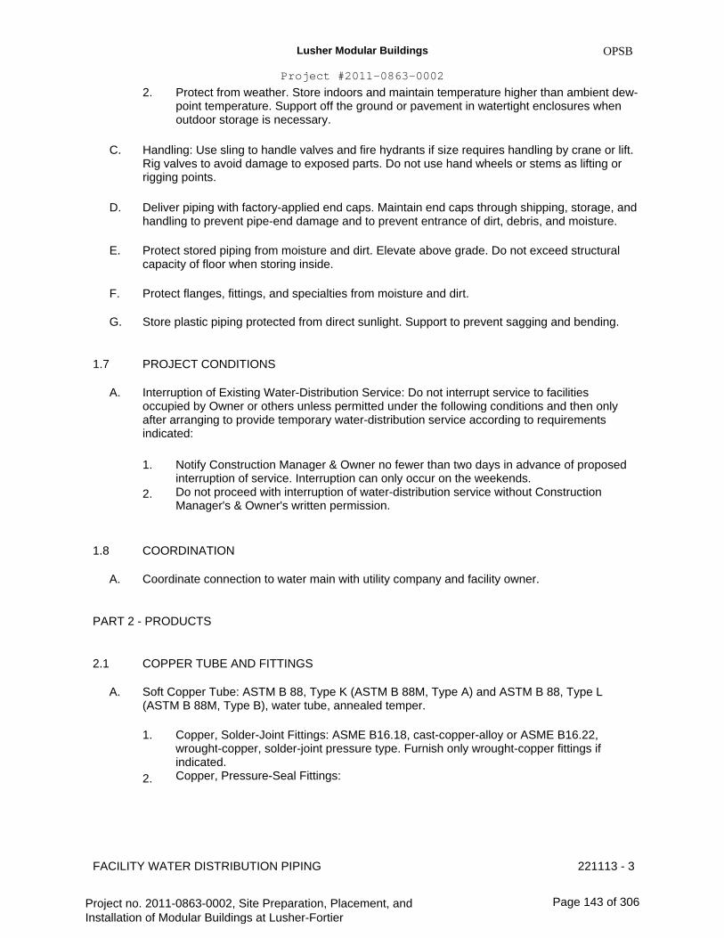
Lusher Modular Buildings
Project #2011-0863-0002
2.
OPSB
Protect from weather. Store indoors and maintain temperature higher than ambient dew- point temperature. Support off the ground or pavement in watertight enclosures when outdoor storage is necessary.
C. Handling: Use sling to handle valves and fire hydrants if size requires handling by crane or lift. Rig valves to avoid damage to exposed parts. Do not use hand wheels or stems as lifting or rigging points.
Deliver piping with factory-applied end caps. Maintain end caps through shipping, storage, and handling to prevent pipe-end damage and to prevent entrance of dirt, debris, and moisture.
Protect stored piping from moisture and dirt. Elevate above grade. Do not exceed structural capacity of floor when storing inside.
Protect flanges, fittings, and specialties from moisture and dirt.
Store plastic piping protected from direct sunlight. Support to prevent sagging and bending.
PROJECT CONDITIONS
D.
E.
F.
G.
1.7
A. Interruption of Existing Water-Distribution Service: Do not interrupt service to facilities occupied by Owner or others unless permitted under the following conditions and then only after arranging to provide temporary water-distribution service according to requirements indicated:
1.
2.
Notify Construction Manager & Owner no fewer than two days in advance of proposed interruption of service. Interruption can only occur on the weekends. Do not proceed with interruption of water-distribution service without Construction Manager's & Owner's written permission.
1.8
A.
COORDINATION
Coordinate connection to water main with utility company and facility owner.
PART 2 - PRODUCTS
2.1
A.
COPPER TUBE AND FITTINGS
Soft Copper Tube: ASTM B 88, Type K (ASTM B 88M, Type A) and ASTM B 88, Type L (ASTM B 88M, Type B), water tube, annealed temper.
1. Copper, Solder-Joint Fittings: ASME B16.18, cast-copper-alloy or ASME B16.22, wrought-copper, solder-joint pressure type. Furnish only wrought-copper fittings if indicated. Copper, Pressure-Seal Fittings: 2.
FACILITY WATER DISTRIBUTION PIPING 221113 - 3
Project no. 2011-0863-0002, Site Preparation, Placement, and Installation of Modular Buildings at Lusher-Fortier
Page 143 of 306

Lusher Modular Buildings
Project #2011-0863-0002
a.
OPSB
b.
Available Manufacturers: Subject to compliance with requirements, manufacturers offering products that may be incorporated into the Work include, but are not limited to, the following: Manufacturers: Subject to compliance with requirements, provide products by one of the following:
1) 2)
Viega; Plumbing & Heating Systems. Approved manufacturer by the Sewerage & Water Board of New Orleans.
c.
d.
B.
NPS 2 (DN 50) and Smaller: Wrought-copper fitting with EPDM O-ring seal in each end. NPS 2-1/2 to NPS 4 (DN 65 to DN 100): Bronze fitting with stainless-steel grip ring and EPDM O-ring seal in each end.
Hard Copper Tube: ASTM B 88, Type K (ASTM B 88M, Type A) and ASTM B 88, Type L (ASTM B 88M, Type B), water tube, drawn temper.
1. Copper, Solder-Joint Fittings: ASME B16.18, cast-copper-alloy or ASME B16.22, wrought-copper, solder-joint pressure type. Furnish only wrought-copper fittings if indicated. Copper, Pressure-Seal Fittings:
a. Available Manufacturers: Subject to compliance with requirements, manufacturers offering products that may be incorporated into the Work include, but are not limited to, the following: Manufacturers: Subject to compliance with requirements, provide products by one of the following:
1) 2)
c.
d.
Viega; Plumbing & Heating Systems. Approved manufacturer by the Sewerage & Water Board of New Orleans.
2.
b.
NPS 2 (DN 50) and Smaller: Wrought-copper fitting with EPDM O-ring seal in each end. NPS 2-1/2 to NPS 4 (DN 65 to DN 100): Bronze fitting with stainless-steel grip ring and EPDM O-ring seal in each end.
C.
D.
Bronze Flanges: ASME B16.24, Class 150, with solder-joint end. Furnish Class 300 flanges if required to match piping.
Copper Unions: MSS SP-123, cast-copper-alloy, hexagonal-stock body with ball-and-socket, metal-to-metal seating surfaces, and solder-joint or threaded ends.
DUCTILE-IRON PIPE AND FITTINGS2.2
A. Mechanical-Joint, Ductile-Iron Pipe: AWWA C151, with mechanical-joint bell and plain spigot end unless grooved or flanged ends are indicated.
1. Mechanical-Joint, Ductile-Iron Fittings: AWWA C110, ductile- or gray-iron standard pattern or AWWA C153, ductile-iron compact pattern.
FACILITY WATER DISTRIBUTION PIPING 221113 - 4
Project no. 2011-0863-0002, Site Preparation, Placement, and Installation of Modular Buildings at Lusher-Fortier
Page 144 of 306

Lusher Modular Buildings
Project #2011-0863-0002
2.
B.
OPSB
Glands, Gaskets, and Bolts: AWWA C111, ductile- or gray-iron glands, rubber gaskets, and steel bolts.
Push-on-Joint, Ductile-Iron Pipe: AWWA C151, with push-on-joint bell and plain spigot end unless grooved or flanged ends are indicated.
1.
2.
Push-on-Joint, Ductile-Iron Fittings: AWWA C110, ductile- or gray-iron standard pattern or AWWA C153, ductile-iron compact pattern. Gaskets: AWWA C111, rubber.
C. Grooved-Joint, Ductile-Iron Pipe: AWWA C151, with cut, rounded-grooved ends.
1. Grooved-End, Ductile-Iron Pipe Appurtenances:
a. Available Manufacturers: Subject to compliance with requirements, manufacturers offering products that may be incorporated into the Work include, but are not limited to, the following: Manufacturers: Subject to compliance with requirements, provide products by one of the following:
1) 2) 3)
c.
d.
Anvil International, Inc. Victaulic Company of America. Approved manufacturer by the Sewerage & Water Board of New Orleans.
b.
Grooved-End, Ductile-Iron Fittings: ASTM A 47/A 47M, malleable-iron castings or ASTM A 536, ductile-iron castings with dimensions matching pipe. Grooved-End, Ductile-Iron-Piping Couplings: AWWA C606, for ductile-iron-pipe dimensions. Include ferrous housing sections, gasket suitable for water, and bolts and nuts.
D.
2.3
A.
Flanges: ASME 16.1, Class 125, cast iron.
PE PIPE AND FITTINGS
PE, ASTM Pipe: ASTM D 2239, SIDR No. 5.3, 7, or 9; with PE compound number required to give pressure rating not less than 200 psig.
1.
2.
Insert Fittings for PE Pipe: ASTM D 2609, made of PA, PP, or PVC with serrated male insert ends matching inside of pipe. Include bands or crimp rings. Molded PE Fittings: ASTM D 3350, PE resin, socket- or butt-fusion type, made to match PE pipe dimensions and class.
B. PE, AWWA Pipe: AWWA C906, DR No. 7.3, 9, or 9.3; with PE compound number required to give pressure rating not less than 200 psig.
1. PE, AWWA Fittings: AWWA C906, socket- or butt-fusion type, with DR number matching pipe and PE compound number required to give pressure rating not less than 200 psig.
FACILITY WATER DISTRIBUTION PIPING 221113 - 5
Project no. 2011-0863-0002, Site Preparation, Placement, and Installation of Modular Buildings at Lusher-Fortier
Page 145 of 306
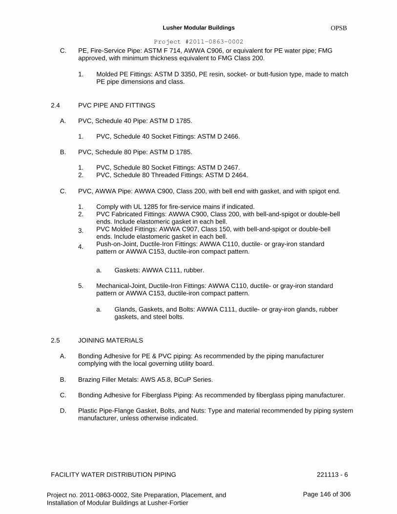
Lusher Modular Buildings
Project #2011-0863-0002
C.
OPSB
PE, Fire-Service Pipe: ASTM F 714, AWWA C906, or equivalent for PE water pipe; FMG approved, with minimum thickness equivalent to FMG Class 200.
1. Molded PE Fittings: ASTM D 3350, PE resin, socket- or butt-fusion type, made to match PE pipe dimensions and class.
2.4
A.
PVC PIPE AND FITTINGS
PVC, Schedule 40 Pipe: ASTM D 1785.
1.
B.
PVC, Schedule 40 Socket Fittings: ASTM D 2466.
PVC, Schedule 80 Pipe: ASTM D 1785.
1. 2.
PVC, Schedule 80 Socket Fittings: ASTM D 2467. PVC, Schedule 80 Threaded Fittings: ASTM D 2464.
C. PVC, AWWA Pipe: AWWA C900, Class 200, with bell end with gasket, and with spigot end.
1. 2.
3.
4.
Comply with UL 1285 for fire-service mains if indicated. PVC Fabricated Fittings: AWWA C900, Class 200, with bell-and-spigot or double-bell ends. Include elastomeric gasket in each bell. PVC Molded Fittings: AWWA C907, Class 150, with bell-and-spigot or double-bell ends. Include elastomeric gasket in each bell. Push-on-Joint, Ductile-Iron Fittings: AWWA C110, ductile- or gray-iron standard pattern or AWWA C153, ductile-iron compact pattern.
a.
5.
Gaskets: AWWA C111, rubber.
Mechanical-Joint, Ductile-Iron Fittings: AWWA C110, ductile- or gray-iron standard pattern or AWWA C153, ductile-iron compact pattern.
a. Glands, Gaskets, and Bolts: AWWA C111, ductile- or gray-iron glands, rubber gaskets, and steel bolts.
2.5
A.
B.
C.
D.
JOINING MATERIALS
Bonding Adhesive for PE & PVC piping: As recommended by the piping manufacturer complying with the local governing utility board.
Brazing Filler Metals: AWS A5.8, BCuP Series.
Bonding Adhesive for Fiberglass Piping: As recommended by fiberglass piping manufacturer.
Plastic Pipe-Flange Gasket, Bolts, and Nuts: Type and material recommended by piping system manufacturer, unless otherwise indicated.
FACILITY WATER DISTRIBUTION PIPING 221113 - 6
Project no. 2011-0863-0002, Site Preparation, Placement, and Installation of Modular Buildings at Lusher-Fortier
Page 146 of 306

Lusher Modular Buildings
Project #2011-0863-0002
2.6
A.
GATE VALVES
OPSB
AWWA, Cast-Iron Gate Valves:
1. Available Manufacturers: Subject to compliance with requirements, manufacturers offering products that may be incorporated into the Work include, but are not limited to, the following: Manufacturers: Subject to compliance with requirements, provide products by one of the following: Basis-of-Design Product: Subject to compliance with requirements set forth by the local governing utility board or a comparable product by one of the following:
a. b. c. d. e. f. g. h. i. j. k. l. m.
4.
American AVK Co.; Valves & Fittings Div. American Cast Iron Pipe Co.; American Flow Control Div. American Cast Iron Pipe Co.; Waterous Co. Subsidiary. Crane Co.; Crane Valve Group; Stockham Div. East Jordan Iron Works, Inc. McWane, Inc.; Clow Valve Co. Div. (Oskaloosa). McWane, Inc.; Kennedy Valve Div. McWane, Inc.; M & H Valve Company Div. McWane, Inc.; Tyler Pipe Div.; Utilities Div. Mueller Co.; Water Products Div. NIBCO INC. U.S. Pipe and Foundry Company. Approved manufacturer by the Sewerage & Water Board of New Orleans.
2.
3.
Non-rising-Stem, Metal-Seated Gate Valves:
a. Description: Gray- or ductile-iron body and bonnet; with cast-iron or bronze double-disc gate, bronze gate rings, bronze stem, and stem nut.
1) 2) 3) 4)
Standard: AWWA C500. Minimum Pressure Rating: 200 psig. End Connections: Mechanical joint. Interior Coating: Complying with AWWA C550.
5. Non-rising-Stem, Resilient-Seated Gate Valves:
a. Description: Gray- or ductile-iron body and bonnet; with bronze or gray- or ductile-iron gate, resilient seats, bronze stem, and stem nut.
1) 2) 3) 4)
Standard: AWWA C509. Minimum Pressure Rating: 200 psig. End Connections: Mechanical joint. Interior Coating: Complying with AWWA C550.
6. Non-rising-Stem, High-Pressure, Resilient-Seated Gate Valves:
a. Description: Ductile-iron body and bonnet; with bronze or ductile-iron gate, resilient seats, bronze stem, and stem nut.
FACILITY WATER DISTRIBUTION PIPING 221113 - 7
Project no. 2011-0863-0002, Site Preparation, Placement, and Installation of Modular Buildings at Lusher-Fortier
Page 147 of 306

Lusher Modular Buildings
Project #2011-0863-0002
1) 2) 3) 4)
7.
Standard: AWWA C509. Minimum Pressure Rating: 250 psig. End Connections: Push on or mechanical joint. Interior Coating: Complying with AWWA C550.
OPSB
OS&Y, Rising-Stem, Metal-Seated Gate Valves:
a. Description: Cast- or ductile-iron body and bonnet, with cast-iron double disc, bronze disc and seat rings, and bronze stem.
1) 2) 3)
Standard: AWWA C500. Minimum Pressure Rating: 200 psig. End Connections: Flanged.
8. OS&Y, Rising-Stem, Resilient-Seated Gate Valves:
a. Description: Cast- or ductile-iron body and bonnet, with bronze or gray- or ductile-iron gate, resilient seats, and bronze stem.
1) 2) 3)
Standard: AWWA C509. Minimum Pressure Rating: 200 psig. End Connections: Flanged.
B. UL/FMG, Cast-Iron Gate Valves:
1. Available Manufacturers: Subject to compliance with requirements, manufacturers offering products that may be incorporated into the Work include, but are not limited to, the following: Manufacturers: Subject to compliance with requirements, provide products by one of the following: Basis-of-Design Product: Subject to compliance with requirements set forth by the local governing utility board or a comparable product by one of the following:
a. b. c. d. e. f. g. h. i. j.
4.
American Cast Iron Pipe Co.; American Flow Control Div. American Cast Iron Pipe Co.; Waterous Co. Subsidiary. Crane Co.; Crane Valve Group; Stockham Div. McWane, Inc.; Clow Valve Co. Div. (Oskaloosa). McWane, Inc.; Kennedy Valve Div. McWane, Inc.; M & H Valve Company Div. Mueller Co.; Water Products Div. NIBCO INC. U.S. Pipe and Foundry Company. Approved manufacturer by the Sewerage & Water Board of New Orleans.
2.
3.
UL/FMG, Non-rising-Stem Gate Valves:
a. Description: Iron body and bonnet with flange for indicator post, bronze seating material, and inside screw.
1) 2)
Standards: UL 262 and FMG approved. Minimum Pressure Rating: 175 psig.
FACILITY WATER DISTRIBUTION PIPING 221113 - 8
Project no. 2011-0863-0002, Site Preparation, Placement, and Installation of Modular Buildings at Lusher-Fortier
Page 148 of 306
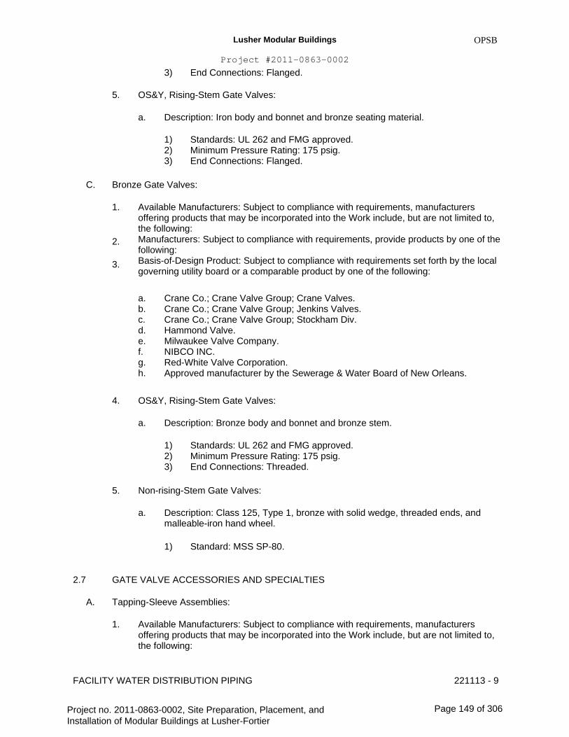
Lusher Modular Buildings
Project #2011-0863-0002
3)
5.
End Connections: Flanged.
OPSB
OS&Y, Rising-Stem Gate Valves:
a. Description: Iron body and bonnet and bronze seating material.
1) 2) 3)
Standards: UL 262 and FMG approved. Minimum Pressure Rating: 175 psig. End Connections: Flanged.
C. Bronze Gate Valves:
1. Available Manufacturers: Subject to compliance with requirements, manufacturers offering products that may be incorporated into the Work include, but are not limited to, the following: Manufacturers: Subject to compliance with requirements, provide products by one of the following: Basis-of-Design Product: Subject to compliance with requirements set forth by the local governing utility board or a comparable product by one of the following:
a. b. c. d. e. f. g. h.
4.
Crane Co.; Crane Valve Group; Crane Valves. Crane Co.; Crane Valve Group; Jenkins Valves. Crane Co.; Crane Valve Group; Stockham Div. Hammond Valve. Milwaukee Valve Company. NIBCO INC. Red-White Valve Corporation. Approved manufacturer by the Sewerage & Water Board of New Orleans.
2.
3.
OS&Y, Rising-Stem Gate Valves:
a. Description: Bronze body and bonnet and bronze stem.
1) 2) 3)
Standards: UL 262 and FMG approved. Minimum Pressure Rating: 175 psig. End Connections: Threaded.
5. Non-rising-Stem Gate Valves:
a. Description: Class 125, Type 1, bronze with solid wedge, threaded ends, and malleable-iron hand wheel.
1) Standard: MSS SP-80.
2.7
A.
GATE VALVE ACCESSORIES AND SPECIALTIES
Tapping-Sleeve Assemblies:
1. Available Manufacturers: Subject to compliance with requirements, manufacturers offering products that may be incorporated into the Work include, but are not limited to, the following:
221113 - 9FACILITY WATER DISTRIBUTION PIPING
Project no. 2011-0863-0002, Site Preparation, Placement, and Installation of Modular Buildings at Lusher-Fortier
Page 149 of 306

Lusher Modular Buildings
Project #2011-0863-0002
2.
3.
OPSB
Manufacturers: Subject to compliance with requirements, provide products by one of the following: Basis-of-Design Product: Subject to compliance with requirements set forth by the governing local utility board or a comparable product by one of the following:
a. b. c. d. e. f. g. h. i.
American Cast Iron Pipe Co.; Waterous Co. Subsidiary. East Jordan Iron Works, Inc. Flowserve. McWane, Inc.; Clow Valve Co. Div. (Oskaloosa). McWane, Inc.; Kennedy Valve Div. McWane, Inc.; M & H Valve Company Div. Mueller Co.; Water Products Div. U.S. Pipe and Foundry Company. Approved manufacturer by the Sewerage & Water Board of New Orleans.
4. Description: Sleeve and valve compatible with drilling machine.
a. b.
Standard: MSS SP-60. Tapping Sleeve: Cast- or ductile-iron or stainless-steel, two-piece bolted sleeve with flanged outlet for new branch connection. Include sleeve matching size and type of pipe material being tapped and with recessed flange for branch valve. Valve: AWWA, cast-iron, nonrising-stem, metal -seated gate valve with one raised face flange mating tapping-sleeve flange.
c.
B. Valve Boxes: Comply with AWWA M44 for cast-iron valve boxes. Include top section, adjustable extension of length required for depth of burial of valve, plug with lettering "WATER," and bottom section with base that fits over valve and with a barrel approximately 5 inches in diameter.
1. Operating Wrenches: Steel, tee-handle with one pointed end, stem of length to operate deepest buried valve, and socket matching valve operating nut.
C. Indicator Posts: UL 789, FMG-approved, vertical-type, cast-iron body with operating wrench, extension rod, and adjustable cast-iron barrel of length required for depth of burial of valve.
CHECK VALVES 2.8
A. AWWA Check Valves:
1. Available Manufacturers: Subject to compliance with requirements, manufacturers offering products that may be incorporated into the Work include, but are not limited to, the following: Manufacturers: Subject to compliance with requirements, provide products by one of the following: Basis-of-Design Product: Subject to compliance with requirements set forth by the local governing utility board or a comparable product by one of the following:
a. b. c.
American AVK Co.; Valves & Fittings Div. American Cast Iron Pipe Co.; American Flow Control Div. APCO Williamette; Valve and Primer Corporation.
2.
3.
FACILITY WATER DISTRIBUTION PIPING 221113 - 10
Project no. 2011-0863-0002, Site Preparation, Placement, and Installation of Modular Buildings at Lusher-Fortier
Page 150 of 306

Lusher Modular Buildings
Project #2011-0863-0002
d. e. f. g. h. i. j. k. l.
4.
Crane Co.; Crane Valve Group; Crane Valves. Crane Co.; Crane Valve Group; Stockham Div. McWane, Inc.; Clow Valve Co. Div. (Oskaloosa). McWane, Inc.; Kennedy Valve Div. McWane, Inc.; M & H Valve Company Div. Mueller Co.; Water Products Div. NIBCO INC. Watts Water Technologies, Inc. Approved manufacturer by the Sewerage & Water Board of New Orleans.
OPSB
Description: Swing-check type with resilient seat. Include interior coating according to AWWA C550 and ends to match piping.
a. b.
Standard: AWWA C508. Pressure Rating: 175 psig.
B. UL/FMG, Check Valves:
1. Available Manufacturers: Subject to compliance with requirements, manufacturers offering products that may be incorporated into the Work include, but are not limited to, the following: Manufacturers: Subject to compliance with requirements, provide products by one of the following: Basis-of-Design Product: Subject to compliance with requirements set forth by the local governing utility board set forth by the local governing utility board or a comparable product by one of the following:
a. b. c. d. e. f. g. h. i. j. k. l. m. n. o. p.
4.
American Cast Iron Pipe Co.; Waterous Co. Subsidiary. Crane Co.; Crane Valve Group; Stockham Div. Globe Fire Sprinkler Corporation. Kidde Fire Fighting. MATCO-NORCA, Inc. McWane, Inc.; Clow Valve Co. Div. (Oskaloosa). McWane, Inc.; Kennedy Valve Div. Mueller Co.; Water Products Div. NIBCO INC. Reliable Automatic Sprinkler Co., Inc. Tyco Fire & Building Products. United Brass Works, Inc. Victaulic Company of America. Viking Corporation. Watts Water Technologies, Inc. Approved manufacturer by the Sewerage & Water Board of New Orleans.
2.
3.
Description: Swing-check type with pressure rating; rubber-face checks, unless otherwise indicated; and ends matching piping.
a. b.
Standards: UL 312 and FMG approved. Pressure Rating: 250 psig.
FACILITY WATER DISTRIBUTION PIPING 221113 - 11
Project no. 2011-0863-0002, Site Preparation, Placement, and Installation of Modular Buildings at Lusher-Fortier
Page 151 of 306

Lusher Modular Buildings
Project #2011-0863-0002
2.9
A.
OPSB
DETECTOR CHECK VALVES
Detector Check Valves:
1. Available Manufacturers: Subject to compliance with requirements, manufacturers offering products that may be incorporated into the Work include, but are not limited to, the following: Manufacturers: Subject to compliance with requirements, provide products by one of the following: Basis-of-Design Product: Subject to compliance with requirements set forth by the local governing utility board or a comparable product by one of the following:
a. b. c. d. e. f. g. h. i. j.
4.
Ames Fire & Waterworks; a division of Watts Regulator Co. Badger Meter, Inc. FEBCO; SPX Valves & Controls. Globe Fire Sprinkler Corporation. McWane, Inc.; Kennedy Valve Div. Mueller Co.; Hersey Meters. Victaulic Company of America. Viking Corporation. Watts Water Technologies, Inc. Approved manufacturer by the Sewerage & Water Board of New Orleans.
2.
3.
Description: Galvanized cast-iron body, bolted cover with air-bleed device for access to internal parts, and flanged ends. Include one-piece bronze disc with bronze bushings, pivot, and replaceable seat. Include threaded bypass taps in inlet and outlet for bypass meter connection. Set valve to allow minimal water flow through bypass meter when major water flow is required.
a. b. c.
Standards: UL 312 and FMG approved. Pressure Rating: 175 psig. Water Meter: AWWA C700, disc type, at least one-fourth size of detector check valve. Include meter, bypass piping, gate valves, check valve, and connections to detector check valve.
5. Description: Iron body, corrosion-resistant clapper ring and seat ring material, flanged ends, with connections for bypass and installation of water meter.
a. b.
Standards: UL 312 and FMG approved. Pressure Rating: 175 psig.
2.10
A.
BUTTERFLY VALVES
AWWA Butterfly Valves:
1. Available Manufacturers: Subject to compliance with requirements, manufacturers offering products that may be incorporated into the Work include, but are not limited to, the following: Manufacturers: Subject to compliance with requirements, provide products by one of the following:
2.
FACILITY WATER DISTRIBUTION PIPING 221113 - 12
Project no. 2011-0863-0002, Site Preparation, Placement, and Installation of Modular Buildings at Lusher-Fortier
Page 152 of 306

Lusher Modular Buildings
Project #2011-0863-0002
3.
OPSB
Basis-of-Design Product: Subject to compliance with requirements set forth by the local governing utility board or a comparable product by one of the following:
a. b. c. d. e. f. g.
DeZURIK/Copes-Vulcan; a unit of SPX Corporation. Milliken Valve Company. Mosser Valve; a division of Olson Technologies, Inc. Mueller Co.; Water Products Div. Pratt, Henry Company. Val-Matic Valve & Manufacturing Corp. Approved manufacturer by the Sewerage & Water Board of New Orleans.
4. Description: Rubber seated.
a. b. c. d.
Standard: AWWA C504. Body: Cast or ductile iron. Body Type: Wafer or flanged. Pressure Rating: 150 psig.
B. UL Butterfly Valves:
1. Available Manufacturers: Subject to compliance with requirements, manufacturers offering products that may be incorporated into the Work include, but are not limited to, the following: Manufacturers: Subject to compliance with requirements, provide products by one of the following: Basis-of-Design Product: Subject to compliance with requirements set forth by the local governing utility board or a comparable product by one of the following:
a. b. c. d. e. f.
4.
McWane, Inc.; Kennedy Valve Div. Milwaukee Valve Company. Mueller Co.; Water Products Div. NIBCO INC. Pratt, Henry Company. Approved manufacturer by the Sewerage & Water Board of New Orleans.
2.
3.
Description: Metal on resilient material seating.
a. b. c. d.
Standards: UL 1091 and FMG approved. Body: Cast or ductile iron. Body Type: Wafer or flanged. Pressure Rating: 175 psig.
2.11
A.
PLUG VALVES
Plug Valves:
1. Available Manufacturers: Subject to compliance with requirements, manufacturers offering products that may be incorporated into the Work include, but are not limited to, the following:
FACILITY WATER DISTRIBUTION PIPING 221113 - 13
Project no. 2011-0863-0002, Site Preparation, Placement, and Installation of Modular Buildings at Lusher-Fortier
Page 153 of 306

Lusher Modular Buildings
Project #2011-0863-0002
2.
3.
OPSB
Manufacturers: Subject to compliance with requirements, provide products by one of the following: Basis-of-Design Product: Subject to compliance with requirements set forth by the local governing utility board or a comparable product by one of the following:
a. b. c. d. e. f. g.
DeZURIK/Copes-Vulcan; a unit of SPX Corporation. Homestead Valve; a division of Olson Technologies, Inc. Milliken Valve Company. McWane, Inc.; M & H Valve Company Div. Pratt, Henry Company. Val-Matic Valve & Manufacturing Corp. Approved manufacturer by the Sewerage & Water Board of New Orleans.
4. Description: Resilient-seated eccentric.
a. b. c. d.
Standard: MSS SP-108. Body: Cast iron. Pressure Rating: 175-psig minimum CWP. Seat Material: Suitable for potable-water service.
2.12
A.
CORPORATION VALVES AND CURB VALVES
Manufacturers:
1. Available Manufacturers: Subject to compliance with requirements, manufacturers offering products that may be incorporated into the Work include, but are not limited to, the following: Manufacturers: Subject to compliance with requirements, provide products by one of the following:
a. b. c. d. e. f. g. h.
Amcast Industrial Corporation; Lee Brass Co. Ford Meter Box Company, Inc. (The); Pipe Products Div. Jones, James Company. Master Meter, Inc. McDonald, A. Y. Mfg. Co. Mueller Co.; Water Products Div. Red Hed Manufacturing & Supply. Approved manufacturer by the Sewerage & Water Board of New Orleans.
2.
B. Service-Saddle Assemblies: Comply with AWWA C800. Include saddle and valve compatible with tapping machine.
1.
2.
3.
Service Saddle: Copper alloy with seal and AWWA C800, threaded outlet for corporation valve. Corporation Valve: Bronze body and ground-key plug, with AWWA C800, threaded inlet and outlet matching service piping material. Manifold: Copper fitting with two to four inlets as required, with ends matching corporation valves and outlet matching service piping material.
FACILITY WATER DISTRIBUTION PIPING 221113 - 14
Project no. 2011-0863-0002, Site Preparation, Placement, and Installation of Modular Buildings at Lusher-Fortier
Page 154 of 306

Lusher Modular Buildings
Project #2011-0863-0002
C.
D.
OPSB
Curb Valves: Comply with AWWA C800. Include bronze body, ground-key plug or ball, and wide tee head, with inlet and outlet matching service piping material.
Service Boxes for Curb Valves: Similar to AWWA M44 requirements for cast-iron valve boxes. Include cast-iron telescoping top section of length required for depth of burial of valve, plug with lettering "WATER," and bottom section with base that fits over curb valve and with a barrel approximately 3 inches in diameter.
1. Shutoff Rods: Steel, tee-handle with one pointed end, stem of length to operate deepest buried valve, and slotted end matching curb valve.
2.13
A.
B.
WATER METERS
Water meters will be furnished by utility company.
Manufacturers:
1. Available Manufacturers: Subject to compliance with requirements, manufacturers offering products that may be incorporated into the Work include, but are not limited to, the following: Manufacturers: Subject to compliance with requirements, provide products by one of the following: Basis-of-Design Product: Subject to compliance with requirements set forth by the local governing utility board or a comparable product by one of the following:
a. b. c. d. e. f. g. h. i.
AMCO Water Metering Systems. Badger Meter, Inc. Carlon Meter. Hays Fluid Controls; a division of ROMAC Industries Inc. McCrometer. Mueller Co.; Hersey Meters. Neptune Technology Group Inc. Sensus Metering Systems. Approved manufacturer by the Sewerage & Water Board of New Orleans.
2.
3.
C. Displacement-Type Water Meters:
1. Description: With bronze main case.
a. b.
Standard: AWWA C700. Registration: Flow in gallons.
D. Turbine-Type Water Meters:
1. Description:
a. b.
Standard: AWWA C701. Registration: Flow in gallons.
E. Compound-Type Water Meters:
FACILITY WATER DISTRIBUTION PIPING 221113 - 15
Project no. 2011-0863-0002, Site Preparation, Placement, and Installation of Modular Buildings at Lusher-Fortier
Page 155 of 306
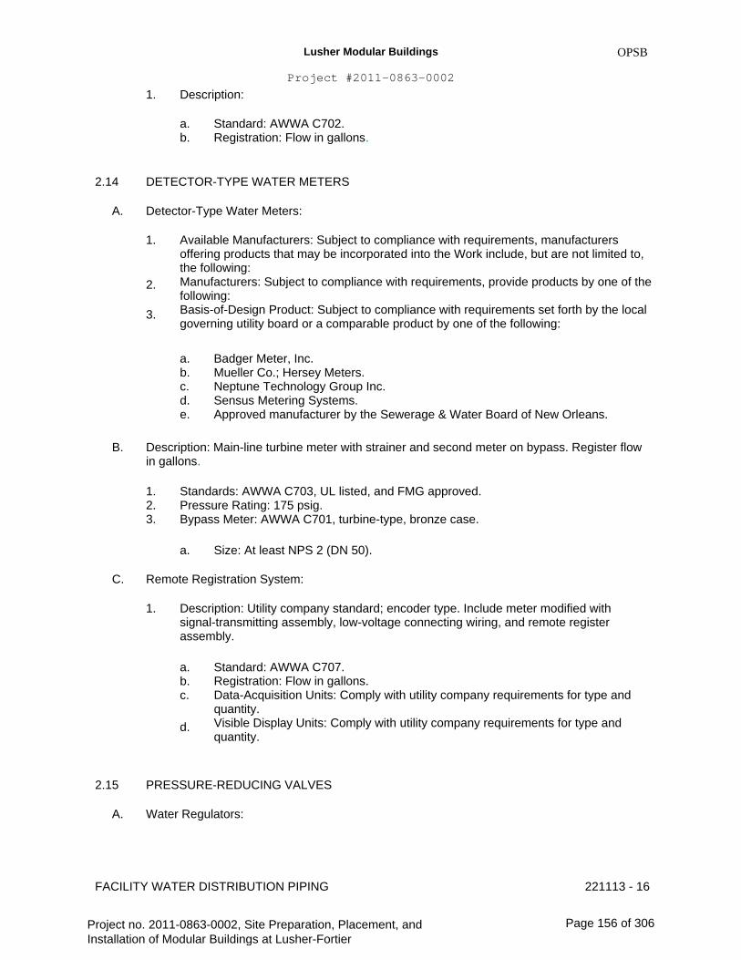
Lusher Modular Buildings
Project #2011-0863-0002
1. Description:
a. b.
2.14
A.
OPSB
Standard: AWWA C702. Registration: Flow in gallons.
DETECTOR-TYPE WATER METERS
Detector-Type Water Meters:
1. Available Manufacturers: Subject to compliance with requirements, manufacturers offering products that may be incorporated into the Work include, but are not limited to, the following: Manufacturers: Subject to compliance with requirements, provide products by one of the following: Basis-of-Design Product: Subject to compliance with requirements set forth by the local governing utility board or a comparable product by one of the following:
a. b. c. d. e.
Badger Meter, Inc. Mueller Co.; Hersey Meters. Neptune Technology Group Inc. Sensus Metering Systems. Approved manufacturer by the Sewerage & Water Board of New Orleans.
2.
3.
B. Description: Main-line turbine meter with strainer and second meter on bypass. Register flow in gallons.
1. 2. 3.
Standards: AWWA C703, UL listed, and FMG approved. Pressure Rating: 175 psig. Bypass Meter: AWWA C701, turbine-type, bronze case.
a. Size: At least NPS 2 (DN 50).
C. Remote Registration System:
1. Description: Utility company standard; encoder type. Include meter modified with signal-transmitting assembly, low-voltage connecting wiring, and remote register assembly.
a. b. c.
d.
Standard: AWWA C707. Registration: Flow in gallons. Data-Acquisition Units: Comply with utility company requirements for type and quantity. Visible Display Units: Comply with utility company requirements for type and quantity.
2.15
A.
PRESSURE-REDUCING VALVES
Water Regulators:
FACILITY WATER DISTRIBUTION PIPING 221113 - 16
Project no. 2011-0863-0002, Site Preparation, Placement, and Installation of Modular Buildings at Lusher-Fortier
Page 156 of 306
Lusher Modular Buildings
Project #2011-0863-0002
1.
OPSB
2.
3.
Available Manufacturers: Subject to compliance with requirements, manufacturers offering products that may be incorporated into the Work include, but are not limited to, the following: Manufacturers: Subject to compliance with requirements, provide products by one of the following: Basis-of-Design Product: Subject to compliance with requirements set forth by the local governing utility board or a comparable product by one of the following:
a. b. c. d. e. f.
Cash Acme; a division of The Reliance Worldwide Corporation. Conbraco Industries, Inc. Honeywell Water Controls. Watts Water Technologies, Inc. Wilkins; a Zurn company. Approved manufacturer by the Sewerage & Water Board of New Orleans.
B. Water Control Valves:
1. Available Manufacturers: Subject to compliance with requirements, manufacturers offering products that may be incorporated into the Work include, but are not limited to, the following: Manufacturers: Subject to compliance with requirements, provide products by one of the following: Basis-of-Design Product: Subject to compliance with requirements set forth by the local governing utility board or a comparable product by one of the following:
a. b. c. d. e. f. g.
4.
CLA-VAL Automatic Control Valves. Flo-matic Corporation. OCV Control Valves. Watts Regulator Co.; Ames Fluid Control Systems. Watts Regulator Co.; Watts ACV Division. Wilkins; a Zurn company. Approved manufacturer by the Sewerage & Water Board of New Orleans.
2.
3.
Description: Pilot-operation, diaphragm-type, single-seated main water control valve with AWWA C550 or FDA-approved, interior epoxy coating. Include small pilot control valve, restrictor device, specialty fittings, and sensor piping.
a. b.
Pressure Rating: Initial pressure of 150 psig minimum. Main Valve Body: Cast- or ductile-iron body with AWWA C550 or FDA- approved, interior epoxy coating; or stainless-steel body.
2.16
A.
RELIEF VALVES
Air-Release Valves:
1. Available Manufacturers: Subject to compliance with requirements, manufacturers offering products that may be incorporated into the Work include, but are not limited to, the following: Manufacturers: Subject to compliance with requirements, provide products by one of the following:
2.
FACILITY WATER DISTRIBUTION PIPING 221113 - 17
Project no. 2011-0863-0002, Site Preparation, Placement, and Installation of Modular Buildings at Lusher-Fortier
Page 157 of 306

Lusher Modular Buildings
Project #2011-0863-0002
3.
OPSB
Basis-of-Design Product: Subject to compliance with requirements set forth by the local governing utility board or a comparable product by one of the following:
a. b. c. d.
Crispin-Multiplex Manufacturing Co. GA Industries, Inc. Val-Matic Valve & Manufacturing Corp. Approved manufacturer by the Sewerage & Water Board of New Orleans.
4.
B.
Description: Hydro-mechanical device to automatically release accumulated air; AWWA Standard: C512.
Air/Vacuum Valves:
1. Available Manufacturers: Subject to compliance with requirements, manufacturers offering products that may be incorporated into the Work include, but are not limited to, the following: Manufacturers: Subject to compliance with requirements, provide products by one of the following: Basis-of-Design Product: Subject to compliance with requirements set forth by the local governing utility board or a comparable product by one of the following:
a. b. c. d.
4.
Crispin-Multiplex Manufacturing Co. GA Industries, Inc. Val-Matic Valve & Manufacturing Corp. Approved manufacturer by the Sewerage & Water Board of New Orleans.
2.
3.
Description: Direct-acting, float-operated, hydro-mechanical device with large orifice to automatically release accumulated air or to admit air during filling of piping; AWWA Standard: C512.
C. Combination Air Valves:
1. Available Manufacturers: Subject to compliance with requirements, manufacturers offering products that may be incorporated into the Work include, but are not limited to, the following: Manufacturers: Subject to compliance with requirements, provide products by one of the following: Basis-of-Design Product: Subject to compliance with requirements set forth by the local governing utility board or a comparable product by one of the following:
a. b. c. d.
4.
Crispin-Multiplex Manufacturing Co. GA Industries, Inc. Val-Matic Valve & Manufacturing Corp. Approved manufacturer by the Sewerage & Water Board of New Orleans.
2.
3.
Description:Float-operated, hydro-mechanical device to automatically release accumulated air or to admit air; AWWA Standard: C512.
FACILITY WATER DISTRIBUTION PIPING 221113 - 18
Project no. 2011-0863-0002, Site Preparation, Placement, and Installation of Modular Buildings at Lusher-Fortier
Page 158 of 306

Lusher Modular Buildings
Project #2011-0863-0002
2.17
A.
VACUUM BREAKERS
OPSB
Pressure Vacuum Breaker Assembly:
1. Available Manufacturers: Subject to compliance with requirements, manufacturers offering products that may be incorporated into the Work include, but are not limited to, the following: Manufacturers: Subject to compliance with requirements, provide products by one of the following: Basis-of-Design Product: Subject to compliance with requirements set forth by the local governing utility board or a comparable product by one of the following:
a. b. c. d. e. f. g. h.
Ames Fire & Waterworks; a division of Watts Regulator Co. Conbraco Industries, Inc. FEBCO; SPX Valves & Controls. Flomatic Corporation. Toro Co. (The); Irrigation Division. Watts Water Technologies, Inc. Wilkins; a Zurn company. Approved manufacturer by the Sewerage & Water Board of New Orleans.
2.
3.
2.18
A.
BACKFLOW PREVENTERS
Reduced-Pressure-Principle Backflow Preventers:
1. Available Manufacturers: Subject to compliance with requirements, manufacturers offering products that may be incorporated into the Work include, but are not limited to, the following: Manufacturers: Subject to compliance with requirements, provide products by one of the following: Basis-of-Design Product: Subject to compliance with requirements set forth by the local governing utility board or a comparable product by one of the following:
a. b. c. d. e. f. g.
Ames Fire & Waterworks; a division of Watts Regulator Co. Conbraco Industries, Inc. FEBCO; SPX Valves & Controls. Flomatic Corporation. Watts Water Technologies, Inc. Wilkins; a Zurn company. Approved manufacturer by the Sewerage & Water Board of New Orleans.
2.
3.
B. Backflow Preventer Test Kits:
1. Available Manufacturers: Subject to compliance with requirements, manufacturers offering products that may be incorporated into the Work include, but are not limited to, the following: Manufacturers: Subject to compliance with requirements, provide products by one of the following: Basis-of-Design Product: Subject to compliance with requirements set forth by the local governing utility board or a comparable product by one of the following:
2.
3.
FACILITY WATER DISTRIBUTION PIPING 221113 - 19
Project no. 2011-0863-0002, Site Preparation, Placement, and Installation of Modular Buildings at Lusher-Fortier
Page 159 of 306
Lusher Modular Buildings
Project #2011-0863-0002
Copyright 2008 AIA
a. b. c. d. e. f.
4.
MASTERSPEC Full Length
Conbraco Industries, Inc. FEBCO; SPX Valves & Controls. Flomatic Corporation. Watts Water Technologies, Inc. Wilkins; a Zurn company. Approved manufacturer by the Sewerage & Water Board of New Orleans.
12/08
Description: Factory calibrated, with gages, fittings, hoses, and carrying case with test- procedure instructions.
2.19
A.
WATER METER BOXES
Description: Cast-iron body and cover for disc-type water meter, with lettering "WATER METER" in cover; and with slotted, open-bottom base section of length to fit over service piping.
1. Option: Base section may be cast-iron, PVC, clay, or other pipe.
B. Description: Cast-iron body and double cover for disc-type water meter, with lettering "WATER METER" in top cover; and with separate inner cover; air space between covers; and slotted, open-bottom base section of length to fit over service piping.
Description: Polymer-concrete body and cover for disc-type water meter, with lettering "WATER" in cover; and with slotted, open-bottom base section of length to fit over service piping. Include vertical and lateral design loadings of 15,000 lb minimum over 10 by 10 inches square.
CONCRETE VAULTS
Description: Precast, reinforced-concrete vault, designed for A-16 load designation according to ASTM C 857 and made according to ASTM C 858.
1. 2.
Ladder: ASTM A 36/A 36M, steel or polyethylene-encased steel steps. Manhole: ASTM A 48/A 48M Class No. 35A minimum tensile strength, gray-iron traffic frame and cover.
a.
3.
Dimension: 24-inch minimum diameter, unless otherwise indicated.
C.
2.20
A.
Manhole: ASTM A 536, Grade 60-40-18, ductile-iron traffic frame and cover.
a. Dimension: 24-inch- minimum diameter, unless otherwise indicated.
4. Drain: ASME A112.6.3, cast-iron floor drain with outlet of size indicated. Include body anchor flange, light-duty cast-iron grate, bottom outlet, and integral or field-installed bronze ball or clapper-type backwater valve.
2.21
A.
PROTECTIVE ENCLOSURES
Freeze-Protection Enclosures:
FACILITY WATER DISTRIBUTION PIPING 221113 - 20
Project no. 2011-0863-0002, Site Preparation, Placement, and Installation of Modular Buildings at Lusher-Fortier
Page 160 of 306
Lusher Modular Buildings
Project #2011-0863-0002
1.
OPSB
2.
3.
Available Manufacturers: Subject to compliance with requirements, manufacturers offering products that may be incorporated into the Work include, but are not limited to, the following: Manufacturers: Subject to compliance with requirements, provide products by one of the following: Basis-of-Design Product: Subject to compliance with requirements set forth by the local governing utility board or a comparable product by one of the following:
a. b. c. d. e. f. g. h. i.
Aqua Shield. BF Products, Inc. DekoRRa Products. Dunco Manufacturing, Inc. G&C Enclosures. Hot Box, Inc. HydroCowl, Inc. Watts Water Technologies, Inc. Approved manufacturer by the Sewerage & Water Board of New Orleans.
4. Description: Insulated enclosure designed to protect aboveground water piping, equipment, or specialties from freezing and damage, with heat source to maintain minimum internal temperature of 40 deg F when external temperatures reach as low as minus 34 deg F.
a. b.
c.
Standard: ASSE 1060. Class I: For equipment or devices other than pressure or atmospheric vacuum breakers. Class I-V: For pressure or atmospheric vacuum breaker equipment or devices. Include drain opening in housing.
1) Housing: Reinforced-aluminum or -fiberglass construction.
a)
b) c) d) e)
2)
Size: Of dimensions indicated, but not less than those required for access and service of protected unit. Drain opening for units with drain connection. Access doors with locking devices. Insulation inside housing. Anchoring devices for attaching housing to concrete base.
Electric heating cable or heater with self-limiting temperature control.
B. Weather-Resistant Enclosures:
1. Available Manufacturers: Subject to compliance with requirements, manufacturers offering products that may be incorporated into the Work include, but are not limited to, the following: Manufacturers: Subject to compliance with requirements, provide products by one of the following: Basis-of-Design Product: Subject to compliance with requirements set forth by the local governing utility board or a comparable product by one of the following:
a. Aqua Shield.
2.
3.
FACILITY WATER DISTRIBUTION PIPING 221113 - 21
Project no. 2011-0863-0002, Site Preparation, Placement, and Installation of Modular Buildings at Lusher-Fortier
Page 161 of 306

Lusher Modular Buildings
Project #2011-0863-0002
b. c. d. e. f. g. h. i.
4.
BF Products, Inc. DekoRRa Products. Dunco Manufacturing, Inc. G&C Enclosures. Hot Box, Inc. HydroCowl, Inc. Watts Water Technologies, Inc. Approved manufacturer by the Sewerage & Water Board of New Orleans.
OPSB
Description: Uninsulated enclosure designed to protect aboveground water piping, equipment, or specialties from weather and damage.
a. b.
c.
Standard: ASSE 1060. Class III: For equipment or devices other than pressure or atmospheric vacuum breakers. Class III-V: For pressure or atmospheric vacuum breaker equipment or devices. Include drain opening in housing.
1) Housing: Reinforced-aluminum or -fiberglass construction.
a)
b) c) d)
Size: Of dimensions indicated, but not less than those required for access and service of protected unit. Drain opening for units with drain connection. Access doors with locking devices. Anchoring devices for attaching housing to concrete base.
C. Expanded-Metal Enclosures:
1. Available Manufacturers: Subject to compliance with requirements, manufacturers offering products that may be incorporated into the Work include, but are not limited to, the following: Manufacturers: Subject to compliance with requirements, provide products by one of the following: Basis-of-Design Product: Subject to compliance with requirements set forth by the local governing utility board or a comparable product by one of the following:
a. b. c. d. e.
4.
Backflow Prevention Device InnClosures, Inc. BF Products, Inc. Cross Brothers, Inc. Le Meur Welding & Manufacturing Co. Approved manufacturer by the Sewerage & Water Board of New Orleans.
2.
3.
Description: Enclosure designed to protect aboveground water piping, equipment, or specialties from damage.
a.
b. c. d.
Material: ASTM F 1267, expanded metal side and top panels, of weight and with reinforcement of same metal at edges as required for rigidity. Type: Type II, expanded and flattened. Class: Class 3, corrosion-resisting steel. Finish: Manufacturer's enamel paint.
FACILITY WATER DISTRIBUTION PIPING 221113 - 22
Project no. 2011-0863-0002, Site Preparation, Placement, and Installation of Modular Buildings at Lusher-Fortier
Page 162 of 306
Lusher Modular Buildings
Project #2011-0863-0002
e.
f. g.
D.
OPSB
Size: Of dimensions indicated, but not less than those required for access and service of protected unit. Locking device. Lugs or devices for securing enclosure to base.
Enclosure Bases:
1. Description: 6-inch minimum thickness precast concrete, of dimensions required to extend at least 6 inches beyond edges of enclosure housings. Include openings for piping.
2.22
A.
FIRE HYDRANTS
Dry-Barrel Fire Hydrants:
1. Available Manufacturers: Subject to compliance with requirements, manufacturers offering products that may be incorporated into the Work include, but are not limited to, the following: Manufacturers: Subject to compliance with requirements, provide products by one of the following: Basis-of-Design Product: Subject to compliance with requirements set forth by the local governing utility board or a comparable product by one of the following:
a. b. c. d. e. f. g. h. i. j. k. l.
4.
American AVK Co.; Valves & Fittings Div. American Cast Iron Pipe Co.; American Flow Control Div. American Cast Iron Pipe Co.; Waterous Co. Subsidiary. American Foundry Group, Inc. East Jordan Iron Works, Inc. McWane, Inc.; Clow Valve Co. Div. (Oskaloosa). McWane, Inc.; Kennedy Valve Div. McWane, Inc.; M & H Valve Company Div. Mueller Co.; Water Products Div. Troy Valve; a division of Penn-Troy Manufacturing, Inc. U.S. Pipe and Foundry Company. Approved manufacturer by the Sewerage & Water Board of New Orleans.
2.
3.
Description: Freestanding, with one NPS 4-1/2 (DN 115) and two NPS 2-1/2 (DN 65) outlets, 5-1/4-inch main valve, drain valve, and NPS 6 (DN 150) mechanical-joint inlet. Include interior coating according to AWWA C550. Hydrant shall have cast-iron body, compression-type valve opening against pressure and closing with pressure.
a. b.
Standard: AWWA C502. Pressure Rating: 150 psig minimum.
5. Description: Freestanding, with one NPS 4-1/2 (DN 115) and two NPS 2-1/2 (DN 65) outlets, 5-1/4-inch main valve, drain valve, and NPS 6 (DN 150) mechanical-joint inlet. Hydrant shall have cast-iron body, compression-type valve opening against pressure and closing with pressure.
a. Standards: UL 246, FMG approved.
FACILITY WATER DISTRIBUTION PIPING 221113 - 23
Project no. 2011-0863-0002, Site Preparation, Placement, and Installation of Modular Buildings at Lusher-Fortier
Page 163 of 306

Lusher Modular Buildings
Project #2011-0863-0002
b. c.
d. e.
f.
B.
OPSB
Pressure Rating: 150 psig minimum. Outlet Threads: NFPA 1963, with external hose thread used by local fire department. Include cast-iron caps with steel chains. Operating and Cap Nuts: Pentagon, 1-1/2 inches point to flat. Direction of Opening: Open hydrant valve by turning operating nut to left or counterclockwise. Exterior Finish: Red alkyd-gloss enamel paint, unless otherwise indicated.
Wet-Barrel Fire Hydrants:
1. Available Manufacturers: Subject to compliance with requirements, manufacturers offering products that may be incorporated into the Work include, but are not limited to, the following: Manufacturers: Subject to compliance with requirements, provide products by one of the following: Basis-of-Design Product: Subject to compliance with requirements set forth by the local governing utility board or a comparable product by one of the following:
a. b. c. d. e. f.
4.
American AVK Co.; Valves & Fittings Div. Jones, James Company. McWane, Inc.; Clow Valve Co. Div. (Corona). McWane, Inc.; Clow Valve Co. Div. (Oskaloosa). Mueller Co.; Water Products Div. Approved manufacturer by the Sewerage & Water Board of New Orleans.
2.
3.
Description: Freestanding, with one NPS 4-1/2 (DN 115) and two NPS 2-1/2 (DN 65) outlets, NPS 6 (DN 150) threaded or flanged inlet, and base section with NPS 6 (DN 150) mechanical-joint inlet. Include interior coating according to AWWA C550.
a. b.
Standard: AWWA C503. Pressure Rating: 150 psig minimum.
5. Description: Freestanding, with one NPS 4-1/2 (DN 115) and two NPS 2-1/2 (DN 65) outlets, NPS 6 (DN 150) threaded or flanged inlet, and base section with NPS 6 (DN 150) mechanical-joint inlet.
a. b. c.
d. e.
f.
Standards: UL 246 and FMG approved. Pressure Rating: 150 psig minimum. Outlet Threads: NFPA 1963, with external hose thread used by local fire department. Include cast-iron caps with steel chains. Operating and Cap Nuts: Pentagon, 1-1/2 inches point to flat. Direction of Opening: Open hydrant valves by turning operating nut to left or counterclockwise. Exterior Finish: Red alkyd-gloss enamel paint, unless otherwise indicated.
2.23
A.
FIRE DEPARTMENT CONNECTIONS
Fire Department Connections:
FACILITY WATER DISTRIBUTION PIPING 221113 - 24
Project no. 2011-0863-0002, Site Preparation, Placement, and Installation of Modular Buildings at Lusher-Fortier
Page 164 of 306
Lusher Modular Buildings
Project #2011-0863-0002
1.
OPSB
2.
3.
Available Manufacturers: Subject to compliance with requirements, manufacturers offering products that may be incorporated into the Work include, but are not limited to, the following: Manufacturers: Subject to compliance with requirements, provide products by one of the following: Basis-of-Design Product: Subject to compliance with requirements set forth by the local governing utility board or a comparable product by one of the following:
a. b. c. d. e. f. g.
Elkhart Brass Mfg. Co., Inc. Fire End & Croker Corporation. Guardian Fire Equipment, Inc. Kidde Fire Fighting. Potter Roemer. Reliable Automatic Sprinkler Co., Inc. Approved manufacturer by the Sewerage & Water Board of New Orleans.
4. Description: Freestanding, with cast-bronze body, thread inlets according to NFPA 1963 and matching local fire department hose threads, and threaded bottom outlet. Include lugged caps, gaskets, and chains; lugged swivel connection and drop clapper for each hose-connection inlet; 18-inch- high brass sleeve; and round escutcheon plate.
a. Standard: UL 405.
2.24
A.
B.
ALARM DEVICES
Alarm Devices, General: UL 753 and FMG approved, of types and sizes to mate and match piping and equipment.
Water-Flow Indicators: Vane-type water-flow detector, rated for 250-psig working pressure; designed for horizontal or vertical installation; with 2 single-pole, double-throw circuit switches to provide isolated alarm and auxiliary contacts, 7 A, 125-V ac and 0.25 A, 24-V dc; complete with factory-set, field-adjustable retard element to prevent false signals and tamperproof cover that sends signal when cover is removed.
Supervisory Switches: Single pole, double throw; designed to signal valve in other than fully open position.
Pressure Switches: Single pole, double throw; designed to signal increase in pressure.
C.
D.
PART 3 - EXECUTION
3.1
A.
EARTHWORK
Refer to Division 31 Section "Earth Moving" for excavating, trenching, and backfilling.
FACILITY WATER DISTRIBUTION PIPING 221113 - 25
Project no. 2011-0863-0002, Site Preparation, Placement, and Installation of Modular Buildings at Lusher-Fortier
Page 165 of 306
Lusher Modular Buildings
Project #2011-0863-0002
3.2
A.
B.
C.
D.
E.
PIPING APPLICATIONS
OPSB
General: Use pipe, fittings, and joining methods for piping systems according to the following applications.
Transition couplings and special fittings with pressure ratings at least equal to piping pressure rating may be used, unless otherwise indicated.
Do not use flanges or unions for underground piping.
Flanges, unions, grooved-end-pipe couplings, and special fittings may be used, instead of joints indicated, on aboveground piping and piping in vaults.
Underground water-service piping NPS 3/4 to NPS 3 shall be the following: 1.PE, ASTM pipe; insert fittings for PE pipe; and clamped joints. 2.PVC, Schedule 80 socket fittings; and solvent-cemented joints.
Underground water-service piping NPS 4 to NPS 8 shall be the following: 1.Ductile-iron; mechanical-joint pipe; ductile-iron, mechanical-joint fittings; and mechanical joints.
Water Meter Box Water-Service Piping NPS 3/4 to NPS 2 shall be same as underground water- service piping.
Aboveground water-service piping NPS 4 to NPS 8 shall be any of the following: 1.Ductile-iron, grooved-end pipe; ductile-iron, grooved-end appurtenances; and grooved joints.
VALVE APPLICATIONS
F.
G.
H.
3.3
A. General Application: Use mechanical-joint-end valves for NPS 3 (DN 80) and larger underground installation. Use threaded- or flanged-end valves for installation in vaults. Use UL/FMG, non rising-stem gate valves for installation with indicator posts. Use corporation valves and curb valves with ends compatible with piping, for NPS 2 (DN 50) and smaller installation.
Drawings indicate valve types to be used. Where specific valve types are not indicated, the following requirements apply:
1.
2.
3.
Underground Valves, NPS 3 (DN 80) and Larger: AWWA, cast-iron, non-rising-stem, high-pressure, resilient seated gate valves with valve box. Underground Valves, NPS 4 (DN 100) and Larger, for Indicator Posts: UL/FMG, cast- iron, non-rising-stem gate valves with indicator post. Use the following for valves in vaults and aboveground:
a. b.
c.
Gate Valves, NPS 2 (DN 50) and Smaller: Bronze, rising stem. Gate Valves, NPS 3 (DN 80) and Larger: AWWA, cast iron, OS&Y rising stem, resilient seated. Check Valves: AWWA C508, swing type.
B.
FACILITY WATER DISTRIBUTION PIPING 221113 - 26
Project no. 2011-0863-0002, Site Preparation, Placement, and Installation of Modular Buildings at Lusher-Fortier
Page 166 of 306

Lusher Modular Buildings
Project #2011-0863-0002
4.
5.
OPSB
Pressure-Reducing Valves: Use for water-service piping in vaults and aboveground to control water pressure. Relief Valves: Use for water-service piping in vaults and aboveground.
a. b.
c.
Air-Release Valves: To release accumulated air. Air/Vacuum Valves: To release or admit large volume of air during filling of piping. Combination Air Valves: To release or admit air.
6. Detector Check Valves: Use for water-service piping in vaults and aboveground to detect unauthorized use of water.
3.4
A.
PIPING SYSTEMS - COMMON REQUIREMENTS
See Division 22 Section "Common Work Results for Plumbing" for piping-system common requirements.
PIPING INSTALLATION
A.
B.
C.
Water-Main Connection: Arrange with utility company for tap of size and in location indicated in water main.
Water-Main Connection: Tap water main according to requirements of water utility company and of size and in location indicated.
Make connections larger than NPS 2 (DN 50) with tapping machine according to the following:
1. 2. 3.
4.
D.
Install tapping sleeve and tapping valve according to MSS SP-60. Install tapping sleeve on pipe to be tapped. Position flanged outlet for gate valve. Use tapping machine compatible with valve and tapping sleeve; cut hole in main. Remove tapping machine and connect water-service piping. Install gate valve onto tapping sleeve. Comply with MSS SP-60. Install valve with stem pointing up and with valve box.
3.5
Make connections NPS 2 (DN 50) and smaller with drilling machine according to the following:
1.
2.
3.
4. 5. 6.
Install service-saddle assemblies and corporation valves in size, quantity, and arrangement required by utility company standards. Install service-saddle assemblies on water-service pipe to be tapped. Position outlets for corporation valves. Use drilling machine compatible with service-saddle assemblies and corporation valves. Drill hole in main. Remove drilling machine and connect water-service piping. Install corporation valves into service-saddle assemblies. Install manifold for multiple taps in water main. Install curb valve in water-service piping with head pointing up and with service box.
E. Comply with NFPA 24 for fire-service-main piping materials and installation.
1. Install PE corrosion-protection encasement according to ASTM A 674 or AWWA C105.
FACILITY WATER DISTRIBUTION PIPING 221113 - 27
Project no. 2011-0863-0002, Site Preparation, Placement, and Installation of Modular Buildings at Lusher-Fortier
Page 167 of 306

Lusher Modular Buildings
Project #2011-0863-0002
2.
F.
OPSB
Install copper tube and fittings according to CDA's "Copper Tube Handbook."
Install ductile-iron, water-service piping according to AWWA C600 and AWWA M41.
1. Install PE corrosion-protection encasement according to ASTM A 674 or AWWA C105.
G.
H.
I.
J.
Install PE pipe according to ASTM D 2774 and ASTM F 645.
Install PVC, AWWA pipe according to ASTM F 645 and AWWA M23.
Install fiberglass AWWA pipe according to AWWA M45.
Bury piping with depth of cover over top at least 30 inches, with top at least 12 inches below level of maximum frost penetration, and according to the following:
1. 2. 3.
Under Driveways: With at least 36 inches cover over top. Under Railroad Tracks: With at least 48 inches cover over top. In Loose Gravelly Soil and Rock: With at least 18 inches additional cover.
K.
L.
Install piping by tunneling or jacking, or combination of both, under streets and other obstructions that cannot be disturbed.
Extend water-service piping and connect to water-supply source and building-water-piping systems at outside face of building wall in locations and pipe sizes indicated.
1. Terminate water-service piping at building wall until building-water-piping systems are installed. Terminate piping with caps, plugs, or flanges as required for piping material. Make connections to building-water-piping systems when those systems are installed.
M. Install underground piping with restrained joints at horizontal and vertical changes in direction. Use restrained-joint piping, thrust blocks, anchors, tie-rods and clamps, and other supports as specified by the sewerage & water board of the City of New Orleans.
JOINT CONSTRUCTION 3.6
A. Make pipe joints according to the following:
1.
2.
3. 4.
Copper-Tubing, Pressure-Sealed Joints: Use proprietary crimping tool and procedure recommended by copper, pressure-seal-fitting manufacturer. Ductile-Iron Piping, Gasketed Joints for Water-Service Piping: AWWA C600 and AWWA M41. Ductile-Iron Piping, Gasketed Joints for Fire-Service-Main Piping: UL 194. Ductile-Iron Piping, Grooved Joints: Cut-groove pipe. Assemble joints with grooved- end, ductile-iron-piping couplings, gaskets, lubricant, and bolts according to coupling manufacturer's written instructions. PE Piping Insert-Fitting Joints: Use plastic insert fittings and fasteners according to fitting manufacturer's written instructions. PVC Piping Gasketed Joints: Use joining materials according to AWWA C900. Construct joints with elastomeric seals and lubricant according to ASTM D 2774 or ASTM D 3139 and pipe manufacturer's written instructions.
5.
6.
FACILITY WATER DISTRIBUTION PIPING 221113 - 28
Project no. 2011-0863-0002, Site Preparation, Placement, and Installation of Modular Buildings at Lusher-Fortier
Page 168 of 306

Lusher Modular Buildings
Project #2011-0863-0002
7.
8.
OPSB
Fiberglass Piping Bonded Joints: Use adhesive and procedure recommended by piping manufacturer. Install dielectric fittings in piping at connections of dissimilar metal piping and tubing.
a. b.
c.
Dielectric Fittings for NPS 2 (DN 50) and Smaller: Use dielectric unions. Dielectric Fittings for NPS 2-1/2 to NPS 4 (DN 65 to DN 100): Use dielectric flange kits. Dielectric Fittings for NPS 5 (DN 125) and Larger: Use dielectric flange kits.
3.7
A.
ANCHORAGE INSTALLATION
Anchorage, General: Install water-distribution piping with restrained joints. Anchorages and restrained-joint types that may be used include the following:
1. 2. 3. 4. 5. 6.
B.
Concrete thrust blocks. Locking mechanical joints. Set-screw mechanical retainer glands. Bolted flanged joints. Heat-fused joints. Pipe clamps and tie rods.
Install anchorages for tees, plugs and caps, bends, crosses, valves, and hydrant branches. Include anchorages for the following piping systems:
1. 2. 3. 4.
Gasketed-Joint, Ductile-Iron, Water-Service Piping: According to AWWA C600. Gasketed-Joint, PVC Water-Service Piping: According to AWWA M23. Bonded-Joint Fiberglass, Water-Service Piping: According to AWWA M45. Fire-Service-Main Piping: According to NFPA 24.
C. Apply full coat of asphalt or other acceptable corrosion-resistant material to surfaces of installed ferrous anchorage devices.
VALVE INSTALLATION 3.8
A.
B.
C.
D.
E.
F.
G.
AWWA Gate Valves: Comply with AWWA C600 and AWWA M44. underground valve with stem pointing up and with valve box.
Install each
AWWA Valves Other Than Gate Valves: Comply with AWWA C600 and AWWA M44.
UL/FMG, Gate Valves: Comply with NFPA 24. Install each underground valve and valves in vaults with stem pointing up and with vertical cast-iron indicator post.
UL/FMG, Valves Other Than Gate Valves: Comply with NFPA 24.
MSS Valves: Install as component of connected piping system.
Corporation Valves and Curb Valves: Install each underground curb valve with head pointed up and with service box.
Pressure-Reducing Valves: Install in vault or aboveground between shutoff valves.
221113 - 29FACILITY WATER DISTRIBUTION PIPING
Project no. 2011-0863-0002, Site Preparation, Placement, and Installation of Modular Buildings at Lusher-Fortier
Page 169 of 306

Lusher Modular Buildings
Project #2011-0863-0002
H.
3.9
A.
3.10
A.
OPSB
Relief Valves: Comply with AWWA C512. Install aboveground with shutoff valve on inlet.
WATER METER INSTALLATION
Install water meters, piping, and specialties according to utility company's written instructions.
ROUGHING-IN FOR WATER METERS
Rough-in piping and specialties for water meter installation according to utility company's written instructions.
VACUUM BREAKER ASSEMBLY INSTALLATION
Install pressure vacuum breaker assemblies of type, size, and capacity indicated. Include valves and test cocks. Install according to requirements of plumbing and health department and authorities having jurisdiction.
Do not install pressure vacuum breaker assemblies in vault or other space subject to flooding.
BACKFLOW PREVENTER INSTALLATION
Install backflow preventers of type, size, and capacity indicated. Include valves and test cocks. Install according to requirements of plumbing and health department and authorities having jurisdiction.
Do not install backflow preventers that have relief drain in vault or in other spaces subject to flooding.
Do not install bypass piping around backflow preventers.
Support NPS 2-1/2 (DN 65) and larger backflow preventers, valves, and piping near floor and on brick or concrete piers.
WATER METER BOX INSTALLATION
Install water meter boxes in paved areas flush with surface.
Install water meter boxes in grass or earth areas with top 2 inches above surface.
CONCRETE VAULT INSTALLATION
Install precast concrete vaults according to ASTM C 891.
3.11
A.
B.
3.12
A.
B.
C.
D.
3.13
A.
B.
3.14
A.
FACILITY WATER DISTRIBUTION PIPING 221113 - 30
Project no. 2011-0863-0002, Site Preparation, Placement, and Installation of Modular Buildings at Lusher-Fortier
Page 170 of 306
Lusher Modular Buildings
Project #2011-0863-0002
3.15
A.
B.
C.
3.16
A.
B.
C.
D.
3.17
A.
OPSB
PROTECTIVE ENCLOSURE INSTALLATION
Install concrete base level and with top approximately 2 inches above grade.
Install protective enclosure over valves and equipment.
Anchor protective enclosure to concrete base.
FIRE HYDRANT INSTALLATION
General: Install each fire hydrant with separate gate valve in supply pipe, anchor with restrained joints or thrust blocks, and support in upright position.
Wet-Barrel Fire Hydrants: Install with valve below frost line. Provide for drainage.
AWWA Fire Hydrants: Comply with AWWA M17.
UL/FMG Fire Hydrants: Comply with NFPA 24.
FLUSHING HYDRANT INSTALLATION
Install post-type flushing hydrants with valve below frost line and provide for drainage. Support in upright position. Include separate gate valve or curb valve and restrained joints in supply piping.
Install ground-type flushing hydrants with valve below frost line and provide for drainage. Install hydrant box flush with grade. Include separate gate valve or curb valve and restrained joints in supply piping.
Install sampling stations with valve below frost line and provide for drainage. Attach weather- resistant housing and support in upright position. Include separate curb valve in supply piping.
FIRE DEPARTMENT CONNECTION INSTALLATION
Install ball drip valves at each check valve for fire department connection to mains.
Install protective pipe bollards on two sides of each fire department connection. Pipe bollards are specified in Division 05 Section "Metal Fabrications."
ALARM DEVICE INSTALLATION
General: Comply with NFPA 24 for devices and methods of valve supervision. Underground valves with valve box do not require supervision.
Supervisory Switches: Supervise valves in open position.
1. Valves: Grind away portion of exposed valve stem. Bolt switch, with plunger in stem depression, to OS&Y gate-valve yoke.
B.
C.
3.18
A.
B.
3.19
A.
B.
FACILITY WATER DISTRIBUTION PIPING 221113 - 31
Project no. 2011-0863-0002, Site Preparation, Placement, and Installation of Modular Buildings at Lusher-Fortier
Page 171 of 306
Lusher Modular Buildings
Project #2011-0863-0002
2.
C.
OPSB
Indicator Posts: Drill and thread hole in upper-barrel section at target plate. Install switch, with toggle against target plate, on barrel of indicator post.
Locking and Sealing: Secure unsupervised valves as follows:
1. 2.
Valves: Install chain and padlock on open OS&Y gate valve. Post Indicators: Install padlock on wrench on indicator post.
D.
E.
F.
Pressure Switches: Drill and thread hole in exposed barrel of fire hydrant. Install switch.
Water-Flow Indicators: Install in water-service piping in vault. Select indicator with saddle and vane matching pipe size. Drill hole in pipe, insert vane, and bolt saddle to pipe.
Connect alarm devices to building fire alarm system. Wiring and fire-alarm devices are specified in Division 28 Section "Fire Detection and Alarm."
CONNECTIONS
Piping installation requirements are specified in other Division 22 Sections. Drawings indicate general arrangement of piping, fittings, and specialties.
See Division 22 Section "Common Work Results for Plumbing" for piping connections to valves and equipment.
Connect water-distribution piping to existing water main. Use tapping sleeve and tapping valve.
Connect water-distribution piping to interior domestic water and fire-suppression piping.
FIELD QUALITY CONTROL
Piping Tests: Conduct piping tests before joints are covered and after concrete thrust blocks have hardened sufficiently. Fill pipeline 24 hours before testing and apply test pressure to stabilize system. Use only potable water.
Hydrostatic Tests: Test at not less than one-and-one-half times working pressure for two hours.
1. Increase pressure in 50-psig increments and inspect each joint between increments. Hold at test pressure for 1 hour; decrease to 0 psig. Slowly increase again to test pressure and hold for 1 more hour. Maximum allowable leakage is 2 quarts per hour per 100 joints. Remake leaking joints with new materials and repeat test until leakage is within allowed limits.
3.20
A.
B.
C.
D.
3.21
A.
B.
C. Prepare reports of testing activities.
FACILITY WATER DISTRIBUTION PIPING 221113 - 32
Project no. 2011-0863-0002, Site Preparation, Placement, and Installation of Modular Buildings at Lusher-Fortier
Page 172 of 306

Lusher Modular Buildings
Project #2011-0863-0002
3.22
A.
IDENTIFICATION
OPSB
Install continuous underground detectable warning tape during backfilling of trench for underground water-distribution piping. Locate below finished grade, directly over piping. Underground warning tapes are specified in Division 31 Section "Earth Moving."
Permanently attach equipment nameplate or marker indicating plastic water-service piping, on main electrical meter panel. See Division 22 Section "Common Work Results for Plumbing" for identifying devices.
CLEANING
Clean and disinfect water-distribution piping as follows:
1.
2.
Purge new water-distribution piping systems and parts of existing systems that have been altered, extended, or repaired before use. Use purging and disinfecting procedure prescribed by authorities having jurisdiction or, if method is not prescribed by authorities having jurisdiction, use procedure described in NFPA 24 for flushing of piping. Flush piping system with clean, potable water until dirty water does not appear at points of outlet. Use purging and disinfecting procedure prescribed by authorities having jurisdiction or, if method is not prescribed by authorities having jurisdiction, use procedure described in AWWA C651 or do as follows:
a.
b.
Fill system or part of system with water/chlorine solution containing at least 50 ppm of chlorine; isolate and allow to stand for 24 hours. Drain system or part of system of previous solution and refill with water/chlorine solution containing at least 200 ppm of chlorine; isolate and allow to stand for 3 hours. After standing time, flush system with clean, potable water until no chlorine remains in water coming from system. Submit water samples in sterile bottles to authorities having jurisdiction. Repeat procedure if biological examination shows evidence of contamination.
B.
3.23
A.
3.
c.
d.
B. Prepare reports of purging and disinfecting activities.
END OF SECTION 221113
FACILITY WATER DISTRIBUTION PIPING 221113 - 33
Project no. 2011-0863-0002, Site Preparation, Placement, and Installation of Modular Buildings at Lusher-Fortier
Page 173 of 306

Lusher Modular Buildings
Project #2011-0863-0002
SECTION 221313 - FACILITY SANITARY SEWERS
PART 1 - GENERAL
1.1
A.
RELATED DOCUMENTS
Drawings and general provisions of the Contract, including General and Supplementary Conditions and Division 01 Specification Sections, apply to this Section.
SUMMARY
A. Section Includes:
1. 2. 3. 4. 5. 6. 7.
1.3
A.
1.4
A.
Pipe and fittings. Non-pressure and pressure couplings. Expansion joints and deflection fittings. Backwater valves. Cleanouts. Encasement for piping. Manholes.
1.2
DEFINITIONS
FRP: Fiberglass-reinforced plastic.
SUBMITTALS
Product Data: For the following:
1. 2.
B.
C.
Expansion joints and deflection fittings. Backwater valves.
Shop Drawings: For manholes. Include plans, elevations, sections, details, and frames and covers.
Coordination Drawings: Show pipe sizes, locations, and elevations. Show other piping in same trench and clearances from sewer system piping. Indicate interface and spatial relationship between manholes, piping, and proximate structures.
Profile Drawings: Show system piping in elevation. Draw profiles to horizontal scale of not less than 1 inch equals 50 feet and to vertical scale of not less than 1 inch equals 5 feet . Indicate manholes and piping. Show types, sizes, materials, and elevations of other utilities crossing system piping.
Product Certificates: For each type of cast-iron soil pipe and fitting, from manufacturer.
D.
E.
FACILITY SANITARY SEWERS 221313 - 1
Project no. 2011-0863-0002, Site Preparation, Placement, and Installation of Modular Buildings at Lusher-Fortier
Page 174 of 306
Lusher Modular Buildings
Project #2011-0863-0002
F.
1.5
A.
B.
C.
1.6
A.
OPSB
Field quality-control reports.
DELIVERY, STORAGE, AND HANDLING
Do not store plastic manholes, pipe, and fittings in direct sunlight.
Protect pipe, pipe fittings, and seals from dirt and damage.
Handle manholes according to manufacturer's written rigging instructions.
PROJECT CONDITIONS
Interruption of Existing Sanitary Sewerage Service: Do not interrupt service to facilities occupied by Owner or others unless permitted under the following conditions and then only after arranging to provide temporary service according to requirements indicated:
1.
2.
Notify Construction Manager & Owner no fewer than two days in advance of proposed interruption of service. Do not proceed with interruption of service without Construction Manager's & Owner's written permission.
PART 2 - PRODUCTS
2.1
A.
B.
C.
D.
2.2
A.
DUCTILE-IRON, GRAVITY SEWER PIPE AND FITTINGS
Pipe: ASTM A 746, for push-on joints.
Standard Fittings: AWWA C110, ductile or gray iron, for push-on joints.
Compact Fittings: AWWA C153, ductile iron, for push-on joints.
Gaskets: AWWA C111, rubber.
DUCTILE-IRON, PRESSURE PIPE AND FITTINGS
Push-on-Joint Piping:
1. 2. 3. 4.
B.
Pipe: AWWA C151. Standard Fittings: AWWA C110, ductile or gray iron. Compact Fittings: AWWA C153. Gaskets: AWWA C111, rubber, of shape matching pipe and fittings.
Mechanical-Joint Piping:
1. 2. 3.
Pipe: AWWA C151, with bolt holes in bell. Standard Fittings: AWWA C110, ductile or gray iron, with bolt holes in bell. Compact Fittings: AWWA C153, with bolt holes in bells.
FACILITY SANITARY SEWERS 221313 - 2
Project no. 2011-0863-0002, Site Preparation, Placement, and Installation of Modular Buildings at Lusher-Fortier
Page 175 of 306
Lusher Modular Buildings
Project #2011-0863-0002
4.
5.
2.3
A.
OPSB
Glands: Cast or ductile iron; with bolt holes and high-strength, cast-iron or high-strength, low-alloy steel bolts and nuts. Gaskets: AWWA C111, rubber, of shape matching pipe, fittings, and glands.
PVC PIPE AND FITTINGS
PVC Cellular-Core Sewer Piping:
1.
2.
B.
Pipe: ASTM F 891, Sewer and Drain Series, PS 50 minimum stiffness, PVC cellular- core pipe with plain ends for solvent-cemented joints. Fittings: ASTM D 3034, SDR 35, PVC socket-type fittings.
PVC Corrugated Sewer Piping:
1. 2. 3.
Pipe: ASTM F 949, PVC corrugated pipe with bell-and-spigot ends for gasketed joints. Fittings: ASTM F 949, PVC molded or fabricated, socket type. Gaskets: ASTM F 477, elastomeric seals.
C. PVC Profile Sewer Piping:
1.
2. 3.
Pipe: ASTM F 794, PVC profile, gravity sewer pipe with bell-and-spigot ends for gasketed joints. Fittings: ASTM D 3034, PVC with bell ends. Gaskets: ASTM F 477, elastomeric seals.
D. PVC Type PSM Sewer Piping:
1.
2. 3.
Pipe: ASTM D 3034, SDR 35, PVC Type PSM sewer pipe with bell-and-spigot ends for gasketed joints. Fittings: ASTM D 3034, PVC with bell ends. Gaskets: ASTM F 477, elastomeric seals.
E. PVC Gravity Sewer Piping:
1. Pipe and Fittings: ASTM F 679, T-2 wall thickness, PVC gravity sewer pipe with bell- and-spigot ends and with integral ASTM F 477, elastomeric seals for gasketed joints.
F. PVC Pressure Piping:
1. 2. 3.
Pipe: AWWA C900, 150 PVC pipe with bell-and-spigot ends for gasketed joints. Fittings: AWWA C900, Class 150 PVC pipe with bell ends. Gaskets: ASTM F 477, elastomeric seals.
G. PVC Water-Service Piping:
1. 2.
Pipe: ASTM D 1785, Schedule 80 PVC, with plain ends for solvent-cemented joints. Fittings: ASTM D 2467, Schedule 80 PVC, socket type.
FACILITY SANITARY SEWERS 221313 - 3
Project no. 2011-0863-0002, Site Preparation, Placement, and Installation of Modular Buildings at Lusher-Fortier
Page 176 of 306
Lusher Modular Buildings
Project #2011-0863-0002
2.4
A.
OPSB
EXPANSION JOINTS AND DEFLECTION FITTINGS
Ductile-Iron Expansion Joints:
1.
2.
Manufacturers: Subject to compliance with requirements, provide products by one of the following: Basis-of-Design Product: Subject to compliance with requirements, provide product indicated on Drawings or comparable product by one of the following:
a. b. c. d. e.
3.
Dresser, Inc. EBAA Iron, Inc. JCM Industries, Inc. Smith-Blair, Inc.; a Sensus company. Approved manufacturer by the Sewerage & Water Board of New Orleans.
Description: Three-piece assembly of telescoping sleeve with gaskets and restrained- type, ductile-iron, bell-and-spigot end sections complying with AWWA C110 or AWWA C153. Include rating for 250-psig minimum working pressure and for expansion indicated.
B. Ductile-Iron Deflection Fittings:
1.
2.
Manufacturers: Subject to compliance with requirements, provide products by one of the following: Basis-of-Design Product: Subject to compliance with requirements, provide product indicated on Drawings or comparable product by one of the following:
a. b.
3.
EBAA Iron, Inc. Approved manufacturer by the Sewerage & Water Board of New Orleans.
Description: Compound coupling fitting with ball joint, flexing section, gaskets, and restrained-joint ends complying with AWWA C110 or AWWA C153. Include rating for 250-psig minimum working pressure and for up to 15 degrees of deflection.
2.5
A.
CLEANOUTS
PVC Cleanouts:
1.
2.
Manufacturers: Subject to compliance with requirements, provide products by one of the following: Basis-of-Design Product: Subject to compliance with requirements, provide product indicated on Drawings or comparable product by one of the following:
a. b. c. d. e. f. g.
Canplas LLC. IPS Corporation. NDS. Plastic Oddities; a division of Diverse Corporate Technologies, Inc. Sioux Chief Manufacturing Company, Inc. Zurn Light Commercial Products Operation; Zurn Plumbing Products Group. Approved manufacturer by the Sewerage & Water Board of New Orleans.
FACILITY SANITARY SEWERS 221313 - 4
Project no. 2011-0863-0002, Site Preparation, Placement, and Installation of Modular Buildings at Lusher-Fortier
Page 177 of 306
Lusher Modular Buildings
Project #2011-0863-0002
3.
OPSB
Description: PVC body with PVC threaded plug. Include PVC sewer pipe fitting and riser to clean out of same material as sewer piping.
2.6
A.
MANHOLES
Standard Precast Concrete Manholes:
1.
2. 3.
4.
Description: ASTM C 478, precast, reinforced concrete, of depth indicated, with provision for sealant joints. Diameter: 48 inches minimum unless otherwise indicated. Ballast: Increase thickness of precast concrete sections or add concrete to base section, as required to prevent flotation. Base Section: 6-inch minimum thickness for floor slab and 4-inch minimum thickness for walls and base riser section; with separate base slab or base section with integral floor. Riser Sections: 4-inch minimum thickness, of length to provide depth indicated. Top Section: Eccentric-cone type unless concentric-cone or flat-slab-top type is indicated; with top of cone of size that matches grade rings. Joint Sealant: ASTM C 990, bitumen or butyl rubber. Resilient Pipe Connectors: ASTM C 923 cast or fitted into manhole walls, for each pipe connection. Steps: As shown in the details; wide enough to allow worker to place both feet on one step and designed to prevent lateral slippage off step. Cast or anchor steps into sidewalls at 12- to 16-inch intervals. Omit steps if total depth from floor of manhole to finished grade is less than 60 inches. Adjusting Rings: Interlocking HDPE rings, with level or sloped edge in thickness and diameter matching manhole frame and cover, and with height as required to adjust manhole frame and cover to indicated elevation and slope. Include sealant recommended by ring manufacturer. Grade Rings: Reinforced-concrete rings, 6- to 9-inch total thickness, with diameter matching manhole frame and cover, and with height as required to adjust manhole frame and cover to indicated elevation and slope.
5. 6.
7. 8.
9.
10.
11.
B. Designed Precast Concrete Manholes:
1. Description:ASTM C 913; designed according to ASTM C 890 for A-16 (ASSHTO HS20-44), heavy-traffic, structural loading; of depth, shape, and dimensions indicated, with provision for sealant joints. Ballast: Increase thickness of one or more precast concrete sections or add concrete to manhole as required to prevent flotation. Joint Sealant: ASTM C 990, bitumen or butyl rubber. Resilient Pipe Connectors: ASTM C 923, cast or fitted into manhole walls, for each pipe connection. Steps: As shown in the details; wide enough to allow worker to place both feet on one step and designed to prevent lateral slippage off step. Cast or anchor steps into sidewalls at 12- to 16-inch intervals. Omit steps if total depth from floor of manhole to finished grade is less than 60 inches. Adjusting Rings: Interlocking HDPE rings, with level or sloped edge in thickness and diameter matching manhole frame and cover, and with height as required to adjust
2.
3. 4.
5.
6.
FACILITY SANITARY SEWERS 221313 - 5
Project no. 2011-0863-0002, Site Preparation, Placement, and Installation of Modular Buildings at Lusher-Fortier
Page 178 of 306

Lusher Modular Buildings
Project #2011-0863-0002
OPSB
7.
manhole frame and cover to indicated elevation and slope. Include sealant recommended by ring manufacturer. Grade Rings: Reinforced-concrete rings, 6- to 9-inch total thickness, with diameter matching manhole frame and cover, and with height as required to adjust manhole frame and cover to indicated elevation and slope.
C. Manhole Frames and Covers:
1. Description: Ferrous; 24-inch ID by 7- to 9-inch riser, with 4-inch- minimum-width flange and 26-inch-diameter cover. Include indented top design with lettering cast into cover, using wording equivalent to "SANITARY SEWER." Material: ASTM A 536, Grade 60-40-18 ductile iron unless otherwise indicated. 2.
D. Manhole-Cover Inserts:
1. 2.
Manufacturers: Subject to compliance with requirements, as shown in the details. Basis-of-Design Product: Subject to compliance with requirements, provide product indicated on Drawings or comparable product by one of the following:
a. b. c. d. e.
3.
FRW Industries; a Syneco Systems, Inc. company. Knutson Enterprises. L. F. Manufacturing, Inc. Parson Environmental Products, Inc. Approved manufacturer by the Sewerage & Water Board of New Orleans.
4.
2.7
A.
Description; Manufactured, plastic form, of size to fit between manhole frame and cover and designed to prevent stormwater inflow. Include handle for removal and gasket for gastight sealing. Type: As shown in the details.
CONCRETE
General: Cast-in-place concrete complying with ACI 318, ACI 350/350R (ACI 350M/350RM), and the following:
1. 2. 3. 4.
B.
Cement: ASTM C 150, Type II. Fine Aggregate: ASTM C 33, sand. Coarse Aggregate: ASTM C 33, crushed gravel. Water: Potable.
Portland Cement Design Mix: 4000 psi minimum, with 0.45 maximum water/cementitious materials ratio.
1. 2.
Reinforcing Fabric: ASTM A 185/A 185M, steel, welded wire fabric, plain. Reinforcing Bars: ASTM A 615/A 615M, Grade 60 (420 MPa) deformed steel.
C. Manhole Channels and Benches: Factory or field formed from concrete. Portland cement design mix, 4000 psi minimum, with 0.45 maximum water/cementitious materials ratio. Include channels and benches in manholes.
FACILITY SANITARY SEWERS 221313 - 6
Project no. 2011-0863-0002, Site Preparation, Placement, and Installation of Modular Buildings at Lusher-Fortier
Page 179 of 306

Lusher Modular Buildings
Project #2011-0863-0002
1.
OPSB
Channels: Concrete invert, formed to same width as connected piping, with height of vertical sides to three-fourths of pipe diameter. Form curved channels with smooth, uniform radius and slope.
a. Invert Slope: 1 percent through manhole.
2. Benches: Concrete, sloped to drain into channel.
a. Slope: 4 percent.
D. Ballast and Pipe Supports: Portland cement design mix, 3000 psi minimum, with 0.58 maximum water/cementitious materials ratio.
1. 2.
Reinforcing Fabric: ASTM A 185/A 185M, steel, welded wire fabric, plain. Reinforcing Bars: ASTM A 615/A 615M, Grade 60 (420 MPa) deformed steel.
PART 3 - EXECUTION
3.1
A.
3.2
A.
EARTHWORK
Excavating, trenching, and backfilling are specified in Division 31 Section "Earth Moving."
PIPING INSTALLATION
General Locations and Arrangements: Drawing plans and details indicate general location and arrangement of underground sanitary sewer piping. Location and arrangement of piping layout take into account design considerations. Install piping as indicated, to extent practical. Where specific installation is not indicated, follow piping manufacturer's written instructions.
Install piping beginning at low point, true to grades and alignment indicated with unbroken continuity of invert. Place bell ends of piping facing upstream. Install gaskets, seals, sleeves, and couplings according to manufacturer's written instructions for using lubricants, cements, and other installation requirements.
Install manholes for changes in direction unless fittings are indicated. Use fittings for branch connections unless direct tap into existing sewer is indicated.
Install proper size increasers, reducers, and couplings where different sizes or materials of pipes and fittings are connected. Reducing size of piping in direction of flow is prohibited.
When installing pipe under streets or other obstructions that cannot be disturbed, use pipe- jacking process of micro-tunneling.
Install gravity-flow, non-pressure, drainage piping according to the following:
1. Install piping pitched down in direction of flow, at minimum slope as indicated on the drawings.
B.
C.
D.
E.
F.
FACILITY SANITARY SEWERS 221313 - 7
Project no. 2011-0863-0002, Site Preparation, Placement, and Installation of Modular Buildings at Lusher-Fortier
Page 180 of 306

Lusher Modular Buildings
Project #2011-0863-0002
2.
OPSB
3. 4.
G.
Install piping NPS 6 (DN 150) and larger with restrained joints at tee fittings and at changes in direction. Use corrosion-resistant rods, pipe or fitting manufacturer's proprietary restraint system, or cast-in-place-concrete supports or anchors. Install ductile-iron, gravity sewer piping according to ASTM A 746. Install PVC gravity sewer piping according to ASTM D 2321 and ASTM F 1668.
Clear interior of piping and manholes of dirt and superfluous material as work progresses. Maintain swab or drag in piping, and pull past each joint as it is completed. Place plug in end of incomplete piping at end of day and when work stops.
PIPE JOINT CONSTRUCTION 3.3
A. Join gravity-flow, non-pressure, drainage piping according to the following: 1.Join ductile-iron, gravity sewer piping according to AWWA C600 for push-on joints. 2.Join PVC gravity sewer piping according to ASTM D 2321 and ASTM D 3034 for elastomeric-seal joints or ASTM D 3034 for elastomeric-gasket joints. 3.Join dissimilar pipe materials with non-pressure-type, rigid couplings.
Pipe couplings, expansion joints, and deflection fittings with pressure ratings at least equal to piping rating may be used in applications below unless otherwise indicated.
1. Use non-pressure flexible couplings where required to join gravity-flow, non-pressure sewer piping unless otherwise indicated.
a. b.
c.
2.
Shielded flexible or rigid couplings for pipes of same or slightly different OD. Unshielded, increaser/reducer-pattern, flexible or rigid couplings for pipes with different OD. Ring-type flexible couplings for piping of different sizes where annular space between smaller piping's OD and larger piping's ID permits installation.
B.
Use pressure pipe couplings for force-main joints.
3.4
A.
B.
C.
D.
E.
F.
MANHOLE INSTALLATION
General: Install manholes complete with appurtenances and accessories indicated.
Install precast concrete manhole sections with sealants according to ASTM C 891.
Install FRP manholes according to manufacturer's written instructions.
Form continuous concrete channels and benches between inlets and outlet.
Set tops of frames and covers flush with finished surface of manholes that occur in pavements. Set tops 3 inches above finished surface elsewhere unless otherwise indicated.
Install manhole-cover inserts in frame and immediately below cover.
FACILITY SANITARY SEWERS 221313 - 8
Project no. 2011-0863-0002, Site Preparation, Placement, and Installation of Modular Buildings at Lusher-Fortier
Page 181 of 306
Lusher Modular Buildings
Project #2011-0863-0002
Copyright 2007 AIA
3.5
A.
3.6
A.
MASTERSPEC Full Length 06/07
CONCRETE PLACEMENT
Place cast-in-place concrete according to ACI 318.
CLEANOUT INSTALLATION
Install cleanouts and riser extensions from sewer pipes to cleanouts at grade. Use cast-iron soil pipe fittings in sewer pipes at branches for cleanouts, and use cast-iron soil pipe for riser extensions to cleanouts. Install piping so cleanouts open in direction of flow in sewer pipe.
1.
B.
C.
Use Heavy-Duty, top-loading classification cleanouts in vehicle-traffic service areas.
Set cleanout frames and covers in earth in cast-in-place-concrete block, 12 by 12 by 6 inches deep. Set with tops 1 inch above surrounding grade.
Set cleanout frames and covers in concrete pavement and roads with tops flush with pavement surface.
CONNECTIONS 3.7
A.
B.
C.
Connect non-pressure, gravity-flow drainage piping to building's sanitary building drains specified in Division 22 Section "Sanitary Waste and Vent Piping."
Connect force-main piping to building's sanitary force mains specified in Division 22 Section "Sanitary Waste and Vent Piping." Terminate piping where indicated.
Make connections to existing piping and underground manholes.
1. Use commercially manufactured wye fittings for piping branch connections. Remove section of existing pipe, install wye fitting into existing piping, and encase entire wye fitting plus 6-inch overlap with not less than 6 inches of concrete with 28-day compressive strength of 3000 psi. Make branch connections from side into existing piping, NPS 4 to NPS 20 (DN 100 to DN 500). Remove section of existing pipe, install wye fitting into existing piping, and encase entire wye with not less than 6 inches of concrete with 28-day compressive strength of 3000 psi. Make branch connections from side into existing piping, NPS 21 (DN 525) or larger, or to underground manholes by cutting opening into existing unit large enough to allow 3 inches of concrete to be packed around entering connection. Cut end of connection pipe passing through pipe or structure wall to conform to shape of and be flush with inside wall unless otherwise indicated. On outside of pipe or manhole wall, encase entering connection in 6 inches of concrete for minimum length of 12 inches to provide additional support of collar from connection to undisturbed ground.
a.
b.
Use concrete that will attain a minimum 28-day compressive strength of 3000 psi unless otherwise indicated. Use epoxy-bonding compound as interface between new and existing concrete and piping materials.
2.
3.
FACILITY SANITARY SEWERS 221313 - 9
Project no. 2011-0863-0002, Site Preparation, Placement, and Installation of Modular Buildings at Lusher-Fortier
Page 182 of 306
Lusher Modular Buildings
Project #2011-0863-0002
4.
OPSB
Protect existing piping and manholes to prevent concrete or debris from entering while making tap connections. Remove debris or other extraneous material that may accumulate.
D.
3.8
A.
Connect to grease interceptors specified in Section "Sanitary Waste Piping Specialties."
CLOSING ABANDONED SANITARY SEWER SYSTEMS
Abandoned Piping: Close open ends of abandoned underground piping indicated to remain in place. Include closures strong enough to withstand hydrostatic and earth pressures that may result after ends of abandoned piping have been closed. Use either procedure below:
1. 2.
Close open ends of piping with at least 8-inch thick, brick masonry bulkheads. Close open ends of piping with threaded metal caps, plastic plugs, or other acceptable methods suitable for size and type of material being closed. Do not use wood plugs.
B. Abandoned Manholes: Excavate around manhole as required and use either procedure below:
1. 2.
Remove manhole and close open ends of remaining piping. Remove top of manhole down to at least 36 inches below final grade. Fill to within 12 inches of top with stone, rubble, gravel, or compacted dirt. Fill to top with concrete.
C.
3.9
A.
Backfill to grade according to Division 31 Section "Earth Moving."
IDENTIFICATION
Materials and their installation are specified in Division 31 Section "Earth Moving." Arrange for installation of green warning tapes directly over piping and at outside edges of underground manholes.
1. 2.
Use detectable warning tape over ferrous piping. Use detectable warning tape over nonferrous piping and over edges of underground manholes.
3.10
A.
FIELD QUALITY CONTROL
Inspect interior of piping to determine whether line displacement or other damage has occurred. Inspect after approximately 24 inches of backfill is in place, and again at completion of Project.
1. 2.
Submit separate report for each system inspection. Defects requiring correction include the following:
a. b.
c. d. e.
Alignment: Less than full diameter of inside of pipe is visible between structures. Deflection: Flexible piping with deflection that prevents passage of ball or cylinder of size not less than 92.5 percent of piping diameter. Damage: Crushed, broken, cracked, or otherwise damaged piping. Infiltration: Water leakage into piping. Exfiltration: Water leakage from or around piping.
FACILITY SANITARY SEWERS 221313 - 10
Project no. 2011-0863-0002, Site Preparation, Placement, and Installation of Modular Buildings at Lusher-Fortier
Page 183 of 306

Lusher Modular Buildings
Project #2011-0863-0002
3.
4.
B.
OPSB
Replace defective piping using new materials, and repeat inspections until defects are within allowances specified. Reinspect and repeat procedure until results are satisfactory.
Test new piping systems, and parts of existing systems that have been altered, extended, or repaired, for leaks and defects.
1. 2.
3.
4. 5.
Do not enclose, cover, or put into service before inspection and approval. Test completed piping systems according to requirements of authorities having jurisdiction. Schedule tests and inspections by authorities having jurisdiction with at least 24 hours' advance notice. Submit separate report for each test. Hydrostatic Tests: Test sanitary sewerage according to requirements of authorities having jurisdiction and the following:
a.
b. c. d. e.
6.
Fill sewer piping with water. Test with pressure of at least 10-foot head of water, and maintain such pressure without leakage for at least 15 minutes. Close openings in system and fill with water. Purge air and refill with water. Disconnect water supply. Test and inspect joints for leaks.
Air Tests: Test sanitary sewerage according to requirements of authorities having jurisdiction, UNI-B-6, and the following:
a. b.
Option: Test plastic gravity sewer piping according to ASTM F 1417. Option:Test concrete gravity sewer piping according to ASTM C 924 (ASTM C 924M).
7.
C.
D.
Manholes: Perform hydraulic test according to ASTM C 969 (ASTM C 969M).
Leaks and loss in test pressure constitute defects that must be repaired.
Replace leaking piping using new materials, and repeat testing until leakage is within allowances specified.
CLEANING
Clean dirt and superfluous material from interior of piping.
3.11
A.
END OF SECTION 221313
FACILITY SANITARY SEWERS 221313 - 11
Project no. 2011-0863-0002, Site Preparation, Placement, and Installation of Modular Buildings at Lusher-Fortier
Page 184 of 306

Lusher Modular Buildings
Project #2011-0863-0002 SECTION 260000
BASIC ELECTRICAL REQUIREMENTS
1.0
1.01
A.
GENERAL
SUMMARY
This section is an extension of the General Requirements (Division 01 of these Specifications) and certain items of a common or administrative nature that pertain to all electrical work.
The work of this section consists of furnishing materials, equipment, constant competent supervision, special tools, test equipment, technicians, and labor necessary for installation of a complete working electrical system as indicated herein and on the Drawings.
MEASUREMENT AND PAYMENT
Electrical work will not be measured.
The payment for work will be included as part of the Contract Lump Sum price including all equipment, labor, and material required for all items addressed in the Division 26 specifications and the electrical drawings. Contractor shall review the documents to determine the full extent of work required. The work includes Division 26 specifications and the electrical drawings, and shall include but not necessarily be limited to the following:
1. Temporary construction power utility service, permits, fee, power usage charges.
2. Utility service raceway installation, pull boxes, and pull lines.
3. Connections to service from points of termination by utility company.
4. Electrical panels.
5. Power distribution feeders and branch circuits.
6. Raceways and fittings.
7. Grounding.
B.
1.02
A.
B.
260000-1
Project no. 2011-0863-0002, Site Preparation, Placement, and Installation of Modular Buildings at Lusher-Fortier
Page 185 of 306
Lusher Modular Buildings
Project #2011-0863-0002
1.03
A.
QUALITY ASSURANCE
The electrical installation shall conform to the requirements of the 2008 edition of the National Electrical Code (NEC). Notify Architect/Engineer of conflicts before performance.
Electrical material shall be built and tested in accordance with the applicable standards of the National Electrical Manufacturers' Association (NEMA), the American National Standards Institute (ANSI) the American Society for Testing and Materials (ASTM), and the Institute of Electrical and Electronic Engineers (IEEE)
Electrical materials shall be new and unused and shall be listed and labeled for the service intended by Underwriters' Laboratories, Inc., where such labeling service is available.
Applicable sections of the following codes and standards shall also be followed:
1. NFPA - National Fire Protection Association including NFPA-101, Life Safety Code.
2. OSHA Code of Federal Regulations (for construction practices).
3. International Building Code (latest edition) as adopted by the State of Louisiana..
4. Applicable state and local codes/ordinances.
5. CBM - Certified Ballast Manufacturer
6. IPCEA - Insulated Power Cable Engineers' Association
7. FM - Factory Mutual
8. ETL - Electrical Testing Laboratories
9. IES - Illuminating Engineering Society
10. NECA – National Electrical Contractors Association
B.
C.
D.
E. Include all items of labor and materials required to comply with the above referenced codes and standards. Where quantities, sizes, or other requirements indicated on Drawings or herein specified are in excess of the requirements of the standards and codes, the Specifications or Drawings shall govern.
260000-2
Project no. 2011-0863-0002, Site Preparation, Placement, and Installation of Modular Buildings at Lusher-Fortier
Page 186 of 306

Lusher Modular Buildings
Project #2011-0863-0002
1.04
A.
REGULATORY REQUIREMENTS
Permits: Obtain and pay for all necessary permits, inspections, connection charges, fees, insurance, bond, licenses, and comply with all governing laws, ordinances, rules and regulations including those of the National Fire Protection Association and all municipal, state or other authority having jurisdiction over the work.
Certificates of Inspection: Upon completion and before the date of substantial completion of each designated Phase, furnish a certificate of inspection issued by the proper authorities to the effect that the installation is in full conformity with all local and state requirements.
COORDINATION
Lay out the work and be responsible for its correctness. Take such measurements as may be necessary to assure approved fitting and proper installation of work, and all other work depending thereon.
Arrange work in a neat, well organized manner with exposed conduit and similar services running parallel with primary lines of the construction elements.
Perform all work in the best and most substantial manner by workmen skilled in the work to be done. Provide adequate supervision at all times.
Cooperate with other contractors to avoid complications between the installation of the various items of equipment. Advise other trades of openings required in their work for the subsequent move-in of large units of electrical equipment.
Locate operating and control equipment properly to provide easy access, and arrange entire electrical work with adequate access for operation and maintenance.
Where the method of installation is not certain, ask for details. Lack of details, not requested, will not be an excuse for improper installation, and any such work must be corrected at the contractors expense.
Coordination Drawings: For locations where several elements of electrical or combined mechanical and electrical work must be sequenced and positioned with precision in order to fit into the available space, prepare coordination drawings showing the actual physical dimensions (at accurate scale, minimum 1/4") required for the installation. Prepare and submit coordination drawings prior to purchase- fabrication-installation of any of the elements involved in the coordination.
All Bidders shall be responsible to insure that equipment selected, switchboards, panelboards, etc., fit in spaces selected, along with NEC compliance. If standard
260000-3
B.
1.05
A.
B.
C.
D.
E.
F.
G.
H.
Project no. 2011-0863-0002, Site Preparation, Placement, and Installation of Modular Buildings at Lusher-Fortier
Page 187 of 306

Lusher Modular Buildings
Project #2011-0863-0002
equipment does not fit, Contractor shall be required to utilize custom equipment as required.
1.06
A.
DRAWINGS AND SPECIFICATIONS
Contract Documents (Drawings and Specifications) are intended to convey the scope of work and indicate general arrangements of equipment, fixtures and piping, and approximate sizes and locations of equipment and outlets. Follow these documents in laying out the work, check all Drawings to become familiar with all conditions affecting the work, and verify spaces in which the work will be installed.
The contract documents are diagrammatic in showing certain but not all, physical relationships which must be established within the electrical work. Its interface with other work including plumbing, fire protection and mechanical work, is the exclusive responsibility of the Contractor. The Drawings show approximate locations only of selected feeders, branch circuits, outlets, etc., except where specific routing or dimensions are indicated. The Architect/Engineer reserves the right to make reasonable changes in locations indicated before roughing-in without additional cost to the Owner.
Because of the small scale of the Drawings, it is not possible to indicate all of the offsets, fittings, and accessories required. Contractor shall investigate the structural and finish conditions affecting Division 26 work and shall arrange such work accordingly, furnishing fittings, bends, junction boxes, pull boxes, access panels, and accessories required to meet such conditions.
These Specifications, together with the accompanying Drawings, contemplate apparatus fully erected, and in satisfactory operating condition with the Contractor furnishing and installing everything that may be necessary to complete the job.
SUBMITTALS
Refer to Section Division 01 for Submittal Requirements. paragraphs are an extension of the applicable sections.
The following
B.
C.
D.
1.07
A.
B. Review of shop drawings shall in no way modify the contract or relieve the Contractor from compliance with the contract.
Names of manufacturers or catalog numbers are listed in the Specification in order to establish a standard for the type, general design and quality of the product required. Where "or equal" is indicated, other products similar in design and of equal quality and complying with the Drawings and Specifications will be considered for acceptance. See Division 01 - Product Requirements.
C.
260000-4
Project no. 2011-0863-0002, Site Preparation, Placement, and Installation of Modular Buildings at Lusher-Fortier
Page 188 of 306
Lusher Modular Buildings
Project #2011-0863-0002
D. Any item not specified herein, but submitted as a substitute for the specified item, shall be submitted in accordance with Division 01 - Product Requirements and accompanied by manufacturer's documentation stating/illustrating the following applicable information in addition to the specific information requested in other sections:
1. Dimensions/weight.
2. Electrical ratings-voltage, amperage, short circuit capability, etc.
3. Construction - gauge of steel/aluminum, paint finish / application method, color, NEMA type, etc.
4. Warranty.
5. Local manufacturer's representative or nearest stocking distributor.
6. Length of time the product has been available to the public.
7. Any deviations.
E. Shop Drawings:
1. Listed below are shop drawings required for transmittal. Refer to Phasing Plan for scheduling of submittal. No time delays will be allowed for failure to be so informed.
a. b. c. d. e. f. g.
Panelboards Raceways Connectors Meter enclosures Circuit Breakers Conductors Conduit Layout Drawings w/ Dimensions
2. Further descriptions or information required with shop drawings shall be included with the description of materials specified herein as follows:
a. Grounding Products: Include a complete grounding system diagram with materials and ground conductor sizes.
b. Housekeeping Pads: Include location and dimensions of housekeeping pads, including blockouts and anchor bolts.
260000-5
Project no. 2011-0863-0002, Site Preparation, Placement, and Installation of Modular Buildings at Lusher-Fortier
Page 189 of 306

Lusher Modular Buildings
Project #2011-0863-0002
c. In preparing shop drawings, establish lines and levels for the work specified and check the drawings to avoid interference with structural features, and the work of other trades.Immediately call to the attention of the Architect/Engineer in writing any interferences for clarification.
3. Corrections or comments made on shop Drawings during the review do not relieve the Contractor from compliance with requirements of the contract documents. Shop Drawings will be checked for general conformance with the design concept of the project and general compliance with information given in the contract documents. Review of the shop Drawings shall not relieve the Contractor from responsibility for confirming and correlating all quantities and dimensions, coordinating work with that of all other trades, and performing work in a safe and satisfactory manner. Review of shop Drawings shall not permit any deviation from Drawings and Specifications. Shop Drawings must be accompanied by signed statement from contractor, stating that he has reviewed the submittal and checked it for compliance.
4. Contractor shall provide products as specified if submittals for review of materials are not received within thirty (30) days after award of the Contract.
1.08
A.
PROTECTION OF APPARATUS
At all times the Contractor shall take precautions necessary to protect his apparatus from damage. Failure on the part of the Contractor to comply with the above to the Architect/Engineer's satisfaction shall be sufficient cause for the rejection of the particular piece of apparatus in question.
PROJECT/SITE CONDITIONS
Visit the site before bidding to become familiar with conditions under which the work will be performed.
No additional compensation will be allowed for failure to be so informed.
CUTTING AND PATCHING
Do all cutting, fitting, and all other work that may be required to make the several parts come together and fit. Cutting for equipment entry shall be under other Divisions. Do not endanger any work by cutting, digging, or otherwise, and do not cut or alter the work of any other Divisions, except with the consent of the Architect/Engineer. Cutting shall be done under the supervision of the Project Superintendent. Patching shall be performed under Division 01.
260000-6
1.09
A.
B.
1.010
A.
Project no. 2011-0863-0002, Site Preparation, Placement, and Installation of Modular Buildings at Lusher-Fortier
Page 190 of 306
Lusher Modular Buildings
Project #2011-0863-0002
B. Provide, properly located and sized, all required chases or openings, etc., required for the work or to conceal any of the work, in any part of the structure.
It is the responsibility of this Division to coordinate with other responsible Divisions for required cutting and patching.
INSERTS AND THIMBLES
Set in place as form work progresses, all necessary inserts and thimbles as may be required. Cutting of beams or of concrete floors or walls will not be permitted.
All thimbles set in concrete shall be of PVC schedule 40 pipe, plain ends, and shall be of proper size to allow for freedom around piping passing through thimble.
Inserts shall be nailed to form work and shall be of size to allow for installation of hangers for the particular pipe served.
RECORD DRAWINGS
Prepare Record Drawings in accordance with the requirements in Division 01.
In addition to the requirements specified in Division 01, indicate the following installed conditions:
1. Equipment locations (exposed and concealed), dimensioned from prominent construction lines.
2. Approved substitutions, Contract Modifications, and actual equipment and materials installed.
3. Contract Modification, actual equipment and materials installed.
4. Complete As-Built Drawings of Division 26 work shown and not shown on the contract drawings in the new and existing facilities.
C.
1.10
A.
B.
C.
1.11
A.
B.
C. Equipment Manuals:
1. Before the date of substantial completion, Contractor shall furnish to the Architect/Engineer three (3) bound sets of descriptive, dimensional and parts data on all major items of electrical equipment and material including those items listed above under "Shop Drawings:".
2. Each set of this literature shall be bound in a permanent type hard cover ring binder and shall be suitably indexed.
260000-7
Project no. 2011-0863-0002, Site Preparation, Placement, and Installation of Modular Buildings at Lusher-Fortier
Page 191 of 306

Lusher Modular Buildings
Project #2011-0863-0002
3. This submittal shall be accompanied by final Electrical Inspection Certificate from the authority having jurisdiction and Statement of Inspection from State Fire Marshal's Office.
1.12
A.
WARRANTY/GUARANTEE
Except where longer periods of warranty are specified, guarantee all labor and materials for a period of twelve (12) months from the date of substantial completion of the particular phase of the work. Repair all defective materials and work; replace with new materials and/or equipment, any material and/or equipment failing to give satisfactory service.
During the period of guarantee, promptly correct any defects in equipment, materials or workmanship without cost to the Owner.
Guarantee includes equipment capacity and performance ratings specified without excessive noise levels. Any deficiencies in equipment specified shall be promptly corrected.
Contractor's warranty shall include an inspection of the system one (1) week before the end of the one (1) year warranty period. Replace or repair any items found to be defective at this time.
TESTS AND BALANCING
At such times as the Engineer / Owner directs, conduct operating tests to demonstrate that the electrical systems are installed and will operate properly and in accordance with the requirements of this Specification. Tests shall be performed in the presence of the Owner’s representative. Furnish instruments and personnel required for such tests.
Perform tests to show Engineer / Owner that the power and lighting loads are equally divided among phases of feeders serving each piece of equipment and each panelboard, and record the results of such tests and turn over to the Architect/Engineer.
Any work and materials tested and found varying from the requirements of the Drawings and Specifications shall be replaced without additional cost to the Owner.
This section does not relieve the Contractor from testing equipment installed under this Division but not listed in this section. Contractor is required to test all equipment, feeders, etc., installed under this Division.
B.
C.
D.
1.13
A.
B.
C.
D.
260000-8
Project no. 2011-0863-0002, Site Preparation, Placement, and Installation of Modular Buildings at Lusher-Fortier
Page 192 of 306
Lusher Modular Buildings
Project #2011-0863-0002
2.0
2.01
A.
PRODUCTS
GENERAL
Refer to DIVISION 01 sections for general requirements on products, materials and equipment. The provisions outlined below expand or modify the requirements as applicable to electrical work. Refer to other DIVISION 26 sections for additional requirements.
Materials and equipment shall conform in all respects to the requirements set forth in these Specifications and the accompanying Drawings.
Provide products which are compatible with other products of the electrical work, and with other work requiring interface with the electrical work, including electrical connections and control devices. For exposed electrical work, coordinate colors and finishes with the Architect/Engineer and as referenced elsewhere in the documents. Determine in advance of purchase that equipment and materials proposed for installation will fit into the confines indicated, leaving adequate clearance as required by applicable codes, and for adjustment, repair, or replacement.
MANUFACTURERS' NAMEPLATES
Each major component of the equipment shall have the manufacturer's name, address, model number, and rating on a plate securely affixed in a conspicuous place. The nameplate of a distributing agent will not be acceptable. NEMA Code ratings, or other data which are die-stamped into the surface of the equipment shall be stamped in an easily visible location.
B.
C.
2.02
3.0
3.01
A.
EXECUTION
GENERAL
Visit the project site before bidding to determine existing conditions and assume all responsibility and bear all expenses in allowing for these conditions in the bid.
Obtain all necessary permits, pay all legal fees and charges, pay all utility charges, and comply with all state and local building codes and safety laws, ordinances and regulations relating to the building and public health and safety. Refer to Division 1 for utility construction demolition, installation, and service connection charge allowances.
No work shall be concealed until approved by the local inspector and all local regulations are adhered to.
260000-9
B.
C.
Project no. 2011-0863-0002, Site Preparation, Placement, and Installation of Modular Buildings at Lusher-Fortier
Page 193 of 306

Lusher Modular Buildings
Project #2011-0863-0002
D. Upon completion, a certificate of approval from the appropriate regulatory agency shall be furnished to the Architect/Engineer.
Cooperate with other trades in installing work in order that there will be no conflict of space required by conduit, piping, outlets, etc. If an interference develops, it shall be referred to the Architect/Engineer for a decision as to which equipment, piping, conduit, etc, is to be relocated. Such relocations shall be made without additional cost to the Owner.
Study all sections of the Specifications and Drawings. Notify Architect/Engineer of conflict between Drawings and Specifications before bidding.The Architect/Engineer's decision will govern.
Electrical Drawings are diagrammatic except where dimensioned. Do not scale. Follow manufacturer's certified shop drawings for accuracy. Consult Architect / Engineer in cases of doubt or conflict. Unless noted as fixed, dimensions are based on the product of one (1) manufacturer. Verify dimensions with certified shop Drawings of the materials actually approved and purchased.
TEMPORARY WIRING, LIGHTING AND POWER AT THE SITE
Furnish and install provisions for temporary electrical service and construction light and power during the construction period conforming to the contract documents, all local code and State labor law requirements. Temporary light and power provisions to be included shall be as hereinafter specified and as required in Section - Temporary Facilities and Services.
Arrange for temporary service with the Utility Company.
Furnish, install, and maintain all temporary service equipment as required until permanent service is installed switch-over of temporary systems on the permanent service when latter is ready for same.
Furnish, install, maintain, and switch on and off on all regular work days a complete temporary light system, for the building while under construction.
Provide any and/or all relocations of temporary electric facilities as necessary to clear the permanent installations of all trades.
WIRING FOR EQUIPMENT BY OTHERS
Electrical service for all equipment furnished under this Specification and/or indicated on the Drawings shall be roughed-in and connected under this Section. It is the responsibility of the Contractor to obtain correct roughing-in dimensions and requirements for this equipment.
260000-10
E.
F.
G.
3.02
A.
A.
B.
C.
D.
3.03
A.
Project no. 2011-0863-0002, Site Preparation, Placement, and Installation of Modular Buildings at Lusher-Fortier
Page 194 of 306

Lusher Modular Buildings
Project #2011-0863-0002 3.04
A.
WORKMANSHIP
Install all materials and electrical components of the work in accordance with instructions of manufacturer following the best modern construction practices and conforming with the Contract Documents. Workmanship shall be first class, in both function and appearance, whether finally concealed or exposed and shall be performed by experienced workmen skilled in the type of work. As practicable, the lines of all components of the system shall be perpendicular or parallel. In general, workmanship shall conform to guidelines set forth in N.E.C.A. manuals.
CLEANING UP
Remove once per week and at the completion of the work all empty cartons, scrap wire, raceways, rubbish, etc., accumulated on the project as a result of work performed.
Remove all marks, stains, fingerprints, bugs, dust and other foreign material from all electrical components. Refinish damaged surfaces and restore original finish to the satisfaction of the Architect/Engineer.
SAFETY
It shall be the Contractor's responsibility to do all things necessary in the pursuit of the installation or testing to provide safe conditions in which to work.
MOUNTING HEIGHTS
Unless otherwise noted on the Drawings or required by the Architect/Engineer, the following mounting heights shall apply:
Panelboards 6'-6" to top
3.05
A.
B.
3.06
A.
3.07
A.
B. Upon approval of the Architect / Engineer mounting heights may be adjusted, Except where mounting heights are indicated by code.
END OF SECTION 260000
260000-11
Project no. 2011-0863-0002, Site Preparation, Placement, and Installation of Modular Buildings at Lusher-Fortier
Page 195 of 306

Lusher Modular Buildings
Project #2011-0863-0002
SECTION 260050
ELECTRICAL RELATED WORK
1.0
1.01
A.
GENERAL
SUMMARY
Extent of electrical related work required by this section is indicated on Drawings and/or specified in Division 26, 27, 28 sections.
Types of electrical related work specified in this section include the following:
1. Excavating, Trenching and Backfill for Electrical Work.
2. Foundations and Supports.
3. Concrete for Electrical Work:
a. b. c. d. e.
1.02
A.
Encasement of electrical work. Underground structural concrete to accommodate electrical work. Electrical equipment foundations and mounting pads. Rough grouting in and around electrical work. Patching concrete which has been cut to accommodate electrical work.
B.
PROJECT/SITE CONDITIONS
Protect property from damages which might result from excavating and backfilling.
Protect persons from injury at excavations by barricades, warnings and illumination.
Coordinate excavations with weather conditions, to minimize possibility of washouts, settlements and other damages and hazards.
PRODUCTS
ACCESS TO ELECTRICAL WORK
Where pull boxes and similar elements of electrical work are located below grade, provide removable access doors of types and sizes needed for access requirements.
B.
C.
2.0
2.01
A.
260050-1
Project no. 2011-0863-0002, Site Preparation, Placement, and Installation of Modular Buildings at Lusher-Fortier
Page 196 of 306

Lusher Modular Buildings
Project #2011-0863-0002
2.02
A.
B.
3.0
3.01
A.
EXCAVATING FOR ELECTRICAL WORK
Backfill Materials: Refer to Division 31 Section, Earthwork.
MATERIALS OF CONCRETE WORK: Refer to Division 3 Section, Concrete.
EXECUTION
EXCAVATION, TRENCHING AND BACKFILLING
Perform all excavation of every description and of whatever substances encountered to the depths indicated on the Drawings or as otherwise specified. During excavation, material suitable for backfilling shall be piled in an orderly manner a sufficient distance from the banks of the trench to avoid overloading and to prevent slides or cave-ins. All excavated materials not required or not suitable for backfill shall be removed and wasted or removed from jobsite as indicated on the Drawings or as directed by Architect at no additional cost to Owner.
Sheeting and shoring shall be done as necessary for the protection of the work and for the safety of personnel. Provide necessary pumping and/or well pointing at all times to maintain a dry working condition in all trenches. Unless otherwise indicated, excavations shall be by open cut except that short sections of a trench may be tunneled if, in the opinion of the Architect the conduit can be safely and properly installed and backfill can be properly tamped in such tunneled sections.
No excavation or trenches shall be cut near or under footings without first consulting Architect / Engineer.
Bottom of trench shall be shaped to give substantially uniform circumferential support to lower third of each pipe. Each pipe shall be laid true to line and grade and in such manner as to form a close concentric joint with adjoining pipe and to prevent sudden offset to flow line. As work progresses, interior of pipe shall be cleared of dirt and superfluous materials of every description.
Wherever wet or otherwise unstable soil that is incapable of properly supporting the pipe, as determined by the Architect / Engineer is encountered in the bottom of the trench, such soil shall be removed to the depth required and the trench backfilled to the proper grade with coarse sand, fine gravel, or other suitable material, and approved by the Architect / Engineer.
Trenches for utilities shall be of a depth that will provide the following minimum depth of cover from existing grade or from indicated finish grade, whichever is lower, unless otherwise specifically shown:
B.
C.
D.
E.
F.
260050-2
Project no. 2011-0863-0002, Site Preparation, Placement, and Installation of Modular Buildings at Lusher-Fortier
Page 197 of 306
Lusher Modular Buildings
Project #2011-0863-0002
1. 30-Inch Minimum Cover - Electrical Conduits/Cables over 600 volts
2. 24-Inch Maximum (See NEC 300-5) - Electrical Cables/Conduits Under 600 volts.
3. 36-Inch Minimum for Utility Service Cables/Conduits.
G. Backfill shall be installed in layers 6" deep, adequately wetted and tamped using materials as noted above. The surface shall be graded to a reasonable uniformity and the mounding over trenches left in a uniform and neat condition as approved by the Architect. Refer to Division 31 for compaction densities.
Service lateral that are not encased in concrete and that are buried 18 in. or more below grade shall have their location identified by a warning ribbon that is placed in the trench at least 12 in. above the underground installation.
Restore all hard finished surfaces such as roadways, sidewalks, grass, shrubbery, etc., removed for installation of utilities (and not shown on Drawings or specified to be reworked under other sections of the work) to their original condition using the same type as original materials. Patching concrete roadways shall require dowelling to tie-in matching reinforcement rods or highway mesh to existing roadway. Dowelling shall occur every 18 inches on both sides of the trench. Restore to near original condition acceptable to Architect.
Carefully plan all work to avoid existing utilities and other interferences. The Drawings do not indicate all existing underground utilities. Existing utility lines to be retained that are shown on the Drawings or the locations of which are made known to the Contractor prior to excavation, as well as all utility lines uncovered during excavation operations, shall be protected from damage during excavation and backfilling and, if damaged, shall be repaired by Contractor at his expense. Prior to doing any excavation with power tools, carefully investigate and locate any exiting conduit, pipes, and other lines.
FOUNDATIONS AND SUPPORTS
Provide concrete pedestals, bases, pads, curbs, anchor blocks, anchor bolts, slab inserts, hangers channels, cradles, saddles, etc. for installation of floor mounted equipment such as switchboards, transformers, etc. and apparatus shown on the Drawings and specified in the various sections of Specification Division 26.
Concrete pads for floor mounted electrical equipment shall be 4 inches high, unless otherwise indicated, poured integral with the floor slab wherever practical. Wherever integral slab poured pads are not practicable, construct 4 inch high housekeeping pads, reinforced with No. 3 steel wire mesh 6 X 6 inches, fastened
260050-3
H.
I.
J.
3.02
A.
B.
Project no. 2011-0863-0002, Site Preparation, Placement, and Installation of Modular Buildings at Lusher-Fortier
Page 198 of 306

Lusher Modular Buildings
Project #2011-0863-0002
to structural slabs with 1/2 inch diameter bolts embedded in structural slabs with expansion bolts at all corners (inset 3 inches) and no further apart than 18 inches. Score structural slab thoroughly to assure concrete bonding between structural slab and housekeeping pad. Construct in full accordance with "concrete" specifications for 2500 psi minimum compressive strength. Finish tops of housekeeping pads smooth and level within 1 percent of span. Pads shall be extended at least 4" (10 cm) beyond the equipment outline on all four sides.
3.03
A.
CUTTING AND PATCHING
Comply with the requirements of other DIVISIONS for cutting and patching of other work to accommodate the installation of electrical work. Except as individually authorized by the Architect/Engineer, cutting and patching of electrical work to accommodate the installation of other work is not permitted. Coordinate all cutting and patching of walls and ceiling with other Divisions, to install and conceal new raceway in existing finished areas.
PAINTING
Factory painted equipment shall have finish restored to Manufacturer's finish if scratched or damaged before acceptance or use by Owner.
3.04
A.
END OF SECTION
260050-4
Project no. 2011-0863-0002, Site Preparation, Placement, and Installation of Modular Buildings at Lusher-Fortier
Page 199 of 306

Lusher Modular Buildings
Project #2011-0863-0002 SECTION 260519 - CONDUCTORS AND CABLES
PART 1 - GENERAL
1.1
A.
SUMMARY
This Section includes the following:
1. 2.
1.2
A.
B.
1.3
A.
Wires and cables rated 2000 V and less. Connectors, splices, and terminations rated 600 V and less.
SUBMITTALS
Product Data: For each type of product indicated.
Field quality-control test reports.
QUALITY ASSURANCE
Electrical Components, Devices, and Accessories: Listed and labeled as defined in NFPA 70, Article 100, by a testing agency acceptable to authorities having jurisdiction, and marked for intended use.
Comply with NFPA 70. B.
PART 2 - PRODUCTS
2.1
A.
B.
CONDUCTORS AND CABLES
Copper Conductors: Comply with NEMA WC 70.
Conductor Insulation: Comply with NEMA WC 70 for Types THWN, XHHW. EPDM for type W.
CONNECTORS AND SPLICES
Manufacturers: Subject to compliance with requirements, provide products by one of the following:
1. 2.
Ilsco type PDSS Elastimold type USB-S
2.2
A.
260519-1
Project no. 2011-0863-0002, Site Preparation, Placement, and Installation of Modular Buildings at Lusher-Fortier
Page 200 of 306
Lusher Modular Buildings
Project #2011-0863-0002
B. Description: Factory-fabricated submersible set screw connectors, number of ports as required, four port minimum, for wire size and ampacity rating required.
PART 3 - EXECUTION
3.1
A.
B.
CONDUCTOR MATERIAL APPLICATIONS
Feeders: Copper. Solid for No. 10 AWG and smaller; stranded for No. 8 AWG and larger.
Branch Circuits: Copper. Solid for No. 10 AWG and smaller; stranded for No. 8 AWG and larger.
CONDUCTOR INSULATION APPLICATIONS AND WIRING METHODS
Service Entrance: Type THWN or XHHW, single conductors in raceway.
Exposed Feeders: Type THWN or XHHW, single conductors in raceway.
Feeders Concealed in Concrete, below Slabs-on-Grade, Type THWN or XHHW, single conductors in raceway.
and Underground:
3.2
A.
B.
C.
D.
E.
Branch Circuits Concealed in Concrete, below Slabs-on-Grade, and Underground: Type THWN or XHHW, single conductors in raceway.
Exposed Multi-Conductor Power Cable: Type W round, 90 degrees C, UL listed, -40°C to +90°C. Suspended under walkways and piers.
INSTALLATION OF CONDUCTORS AND CABLES
Install all conductors except multi-conductor power cable in raceway.
Use manufacturer-approved pulling compound or lubricant where necessary; compound used must not deteriorate conductor or insulation. Do not exceed manufacturer's recommended maximum pulling tensions and sidewall pressure values.
Use pulling means, including fish tape, cable, rope, and basket-weave wire/cable grips, that will not damage cables or raceway.
Support cables according to Division 26 Section "Electrical Supports and Seismic Restraints."
Identify and color-code conductors and cables according to Division 26 Section "Electrical Identification."
3.3
A.
B.
C.
D.
E.
260519-2
Project no. 2011-0863-0002, Site Preparation, Placement, and Installation of Modular Buildings at Lusher-Fortier
Page 201 of 306

Lusher Modular Buildings
Project #2011-0863-0002
F. Tighten electrical connectors and terminals according to manufacturer's published torque-tightening values. If manufacturer's torque values are not indicated, use those specified in UL 486A and UL 486B.
Make splices and taps with submersible connectors that are compatible with conductor material and that possess equivalent or better mechanical strength and insulation ratings than unspliced conductors.
1. Use oxide inhibitor in each splice and tap conductor.
G.
H.
3.4
A.
B.
Wiring at junction boxes: Install conductor with at least 12 inches (300 mm) of slack.
FIELD QUALITY CONTROL
Perform tests and inspections and prepare test reports.
Tests and Inspections:
1.
2.
After installing conductors and cables and before electrical circuitry has been energized, test all conductors for compliance with requirements.
Perform each visual and mechanical inspection and electrical test stated in NETA Acceptance Testing Specification. Certify compliance with test parameters.
C. Test Reports: Prepare a written report to record the following:
1. 2. 3.
Test procedures used. Test results that comply with requirements. Test results that do not comply with requirements and corrective action taken to achieve compliance with requirements.
D. Remove and replace malfunctioning units and retest as specified above.
END OF SECTION 260519
260519-3
Project no. 2011-0863-0002, Site Preparation, Placement, and Installation of Modular Buildings at Lusher-Fortier
Page 202 of 306

Lusher Modular Buildings
Project #2011-0863-0002 SECTION 260526 - GROUNDING AND BONDING
PART 1 - GENERAL
1.1
A.
1.2
A.
B.
1.3
A.
SUMMARY
Section Includes: Grounding systems and equipment.
SUBMITTALS
Product Data: For each type of product indicated.
Field quality-control reports.
QUALITY ASSURANCE
Electrical Components, Devices, and Accessories: Listed and labeled as defined in NFPA 70, by a qualified testing agency, and marked for intended location and application.
Comply with UL 467 for grounding and bonding materials and equipment. B.
PART 2 - PRODUCTS
2.1
A.
B.
CONDUCTORS
Insulated Conductors: Copper wire or cable insulated for 600 V unless otherwise required by applicable Code or authorities having jurisdiction.
Bare Copper Conductors:
1. 2. 3.
2.2
A.
Solid Conductors: ASTM B 3. Stranded Conductors: ASTM B 8. Bonding Conductor: No. 4 or No. 6 AWG, stranded conductor.
CONNECTORS
Listed and labeled by an NRTL acceptable to authorities having jurisdiction for applications in which used and for specific types, sizes, and combinations of conductors and other items connected.
260526-1
Project no. 2011-0863-0002, Site Preparation, Placement, and Installation of Modular Buildings at Lusher-Fortier
Page 203 of 306

Lusher Modular Buildings
Project #2011-0863-0002
B. Welded Connectors:Exothermic-welding kits of types recommended by kit manufacturer for materials being joined and installation conditions.
GROUNDING ELECTRODES
Ground Rods: Stainless steel 3/4 inch diameter by 96 inches long.
2.3
A.
PART 3 - EXECUTION
3.1
A.
B.
APPLICATIONS
Conductors: Install solid conductor for No. 10 AWG and smaller, and stranded conductors for No. 8 AWG and larger unless otherwise indicated.
Conductor Terminations and Connections:
1. 2. 3.
3.2
A.
Equipment Grounding Conductor Terminations: Bolted connectors. Underground Connections: Welded connectors. Connections to Ground Rods: Welded connectors.
EQUIPMENT GROUNDING
Install insulated equipment grounding conductors with the following items, in addition to those required by NFPA 70:
1. Feeders and branch circuits.
3.3
A.
INSTALLATION
Grounding Conductors: Route along shortest and straightest paths possible unless otherwise indicated or required by Code. Avoid obstructing access or placing conductors where they may be subjected to strain, impact, or damage.
Ground Rods: Drive rods until tops are 12 inches (50 mm) below final grade unless otherwise indicated.
1. Interconnect ground rods with grounding electrode conductor below grade and as otherwise indicated. Make connections without exposing steel or damaging coating if any.
B.
C. Bonding Straps and Jumpers: Install in locations accessible for inspection and maintenance except where routed through short lengths of conduit.
260526-2
Project no. 2011-0863-0002, Site Preparation, Placement, and Installation of Modular Buildings at Lusher-Fortier
Page 204 of 306

Lusher Modular Buildings
Project #2011-0863-0002
1.
2.
3.4
A.
Bonding to Structure: Bond straps directly to basic structure, taking care not to penetrate any adjacent parts. Use exothermic-welded connectors for outdoor locations.
LABELING
Comply with requirements in Division 26 Section "Electrical Identification" Article for instruction signs. The label or its text shall be green.
1. Label Text: "If this connector or cable is loose or if it must be removed for any reason, notify the facility manager."
3.5
A.
FIELD QUALITY CONTROL
Perform the following tests and inspections and prepare test reports:
1.
2.
After installing grounding system but before permanent electrical circuits have been energized, test for compliance with requirements. Inspect physical and mechanical condition. Verify tightness of accessible, bolted, electrical connections with a calibrated torque wrench according to manufacturer's written instructions. Test completed grounding system at each location where a maximum ground- resistance level is specified, at service disconnect enclosure grounding terminal, and at ground test wells. Make tests at ground rods before any conductors are connected.
3.
B. Report measured ground resistances that exceed the following values:
1. Power and Lighting Equipment or System with Capacity of 500 kVA and Less: 25 ohms.
C. Excessive Ground Resistance: If resistance to ground exceeds specified values, notify Architect promptly and include recommendations to reduce ground resistance.
END OF SECTION 260526
260526-3
Project no. 2011-0863-0002, Site Preparation, Placement, and Installation of Modular Buildings at Lusher-Fortier
Page 205 of 306

Lusher Modular Buildings
Project #2011-0863-0002
SECTION 260529
SUPPORTING DEVICES
PART 1 - GENERAL
1.01 SUMMARY
A. The work of this section consists of providing labor, materials, tools, appliances and miscellaneous accessories associated with supports, anchors, sleeves and seals indicated herein and on Drawings and schedules.
Types of supports, anchors, sleeves and seals specified in this section include the following:
1. 2. 3. 4. 5. 6. 7. 8.
C.
Riser clamps. C-clamps. I-beam clamps. One-hole conduit straps. Round steel rods. Lead expansion anchors. Channel Uni-strut
B.
Supports, anchors, sleeves and seals furnished as part of factory-fabricated equipment, are specified as part of equipment assembly in other Divisions-16 sections.
1.02 QUALITY ASSURANCE
A. Manufacturers: Firms regularly engaged in manufacture of supporting devices, of types, sizes, and ratings required, whose products have been in satisfactory use in similar service for not less than 3 years.
Installer: Qualified with at least 3 years of successful installation experience on projects with electrical installation work similar to that required for project.
NEC Compliance: Comply with NEC as applicable to construction and installation of electrical supporting devices.
ANSI/NEMA Compliance:Comply with applicable requirements of ANSI/NEMA Std Pub No. FB1, "Fittings and Supports for Conduit and Cable Assemblies".
260529-1
B.
C.
D.
Project no. 2011-0863-0002, Site Preparation, Placement, and Installation of Modular Buildings at Lusher-Fortier
Page 206 of 306
Lusher Modular Buildings
Project #2011-0863-0002 E. MSS Compliance:Comply with applicable MSS standard requirements
pertaining to fabrication and installation practices for pipe hangers and supports.
NECA Compliance: Comply with National Electrical Contractors Association's "Standard of Installation" pertaining to anchors, fasteners, hangers, supports, and equipment mounting.
UL Compliance: Provide electrical components which are UL-listed and labeled.
FS Compliance: Comply with Federal Specification FF-S-760 pertaining to retaining strap for conduit, pipe and cable.
F.
G.
H.
1.03 SUBMITTALS
A. Product Data: Submit catalog cuts, specifications, installation instructions, for each type of support, anchor, sleeve and seal.
PART 2 - PRODUCTS
2.01 MANUFACTURED SUPPORTING DEVICES
A. General: Provide supporting devices complying with manufacturer's standard materials, design and construction in accordance with published product information, and as required for a complete installation, and as herein specified. Where more than one type of device meets indicated requirements, selection is Installer's option.
PART 3 - EXECUTION
3.01 INSTALLATION OF SUPPORTING DEVICES
A. Install hangers, anchors, sleeves and seals in accordance with manufacturer's written instructions and with recognized industry practices to insure supporting devices comply with requirements of NECA, NEC and ANSI/NEMA for installation of supporting devices.
Coordinate with other electrical work, including raceway and wiring work, as necessary to interface installation of supporting devices with other work.
Install hangers, supports, clamps and attachments to support piping properly from building structure. Arrange for grouping of parallel runs of horizontal conduits to be supported together on trapeze type hangers where possible. Install supports with maximum spacings indicated.
260529-2
B.
C.
Project no. 2011-0863-0002, Site Preparation, Placement, and Installation of Modular Buildings at Lusher-Fortier
Page 207 of 306
Lusher Modular Buildings
Project #2011-0863-0002 D. Tighten sleeve seal nuts until sealing grommets have expanded to form watertight
seal.
Coordinate all conduit penetrations, below grade, into building from the exterior with other divisions.
E.
END OF SECTION
260529-3
Project no. 2011-0863-0002, Site Preparation, Placement, and Installation of Modular Buildings at Lusher-Fortier
Page 208 of 306
Lusher Modular Buildings
Project #2011-0863-0002 SECTION 260533 - RACEWAYS AND BOXES
PART 1 - GENERAL
1.1
A.
1.2
A.
B.
SUMMARY
This Section includes raceways, fittings, boxes, enclosures, and cabinets for electrical wiring.
SUBMITTALS
Product Data: For raceways, and junction boxes.
Shop Drawings: For custom enclosures and cabinets. Include plans, elevations, sections, details, and attachments to other work.
QUALITY ASSURANCE
A. Electrical Components, Devices, and Accessories: Listed and labeled as defined in NFPA 70, Article 100, by a testing agency acceptable to authorities having jurisdiction, and marked for intended use.
Comply with NFPA 70.
1.3
B.
PART 2 - PRODUCTS
2.1
A.
B.
METAL CONDUIT AND TUBING
Rigid Steel Conduit: ANSI C80.1.
Fittings for Conduit: NEMA FB 1; listed for type and size raceway with which used, and for application and environment in which installed.
NONMETALLIC CONDUIT AND TUBING
A.
B.
2.3
A.
RNC: NEMA TC 2, Type EPC-40-PVC, unless otherwise indicated.
Fittings for RNC: NEMA TC 3; match to conduit or tubing type and material.
BOXES, ENCLOSURES, AND CABINETS
Nonmetallic direct burial Junction Boxes: ASTM D-2444, D-570, manufactured of polymer concrete, Quazite or equivalent.
2.2
260533-1
Project no. 2011-0863-0002, Site Preparation, Placement, and Installation of Modular Buildings at Lusher-Fortier
Page 209 of 306

Lusher Modular Buildings
Project #2011-0863-0002
PART 3 - EXECUTION
3.1
A.
RACEWAY APPLICATION
Outdoors: Apply raceway products as specified below, unless otherwise indicated: 1.Exposed Conduit: Rigid galvanized steel conduit RGS. 2.Underground Conduit: RNC, Type EPC-40-PVC, direct buried. PVC schedule 80 radius fittings. 3.Exposed junction boxes: galvanized painted steel, NEMA 3R.
Minimum Raceway Size: 3/4-inch trade size.
Raceway Fittings: Compatible with raceways and suitable for use and location.
1.
3.2
A.
B.
C.
D.
E.
F.
G.
Rigid Steel Conduit: Use threaded rigid steel conduit fittings, unless otherwise indicated.
B.
C.
INSTALLATION
Comply with NECA 1 for installation requirements applicable to products specified in Part 2 except where requirements on Drawings or in this Article are stricter.
Keep raceways at least 6 inches (150 mm) away from parallel runs of flues and steam or hot- water pipes. Install horizontal raceway runs above water and steam piping.
Complete raceway installation before starting conductor installation.
Support raceways as specified in Division 26 Section "Electrical Supports and Seismic Restraints."
Arrange stub-ups so curved portions of bends are not visible above the finished grade.
Install no more than the equivalent of three 90-degree bends in any conduit run except for communications conduits, for which fewer bends are allowed.
Raceways below Slabs: 1.Change from ENT to RNC, Type EPC-40-PVC, rigid steel conduit, or IMC before rising above grade.
Install pull lines in empty raceways. Use polypropylene or monofilament plastic line with not less than 200-lb (90-kg) tensile strength. Leave at least 12 inches (300 mm) of slack at each end of pull line.
Set nonmetallic junction boxes level and flush with finished grade or pavement surface.
INSTALLATION OF UNDERGROUND CONDUIT
A. Direct-Buried Conduit:
H.
I.
3.3
260533-2
Project no. 2011-0863-0002, Site Preparation, Placement, and Installation of Modular Buildings at Lusher-Fortier
Page 210 of 306
Lusher Modular Buildings
Project #2011-0863-0002
1.
2. 3.
4.
5.
Excavate trench bottom to provide firm and uniform support for conduit. Prepare trench bottom as specified in Division 31 Section "Earthwork" for pipe less than 6 inches (150 mm) in nominal diameter. Install backfill as specified in Division 31 Section "Earthwork." After installing conduit, backfill and compact. Start at tie-in point, and work toward end of conduit run, leaving conduit at end of run free to move with expansion and contraction as temperature changes during this process. Firmly hand tamp backfill around conduit to provide maximum supporting strength. After placing controlled backfill to within 12 inches (300 mm) of finished grade, make final conduit connection at end of run and complete backfilling with normal compaction as specified in Division 2 Section "Earthwork." Install manufactured duct elbows for stub-ups at junction boxes and equipment unless otherwise indicated. Encase elbows for stub-up ducts throughout the length of the elbow. Install manufactured rigid steel conduit elbows for stub-ups at power poles.
a. Couple steel conduits to ducts with adapters designed for this purpose, and encase coupling with 3 inches (75 mm) of concrete.
6. Warning Planks: Bury warning planks approximately 12 inches (300 mm) above direct- buried conduits, placing them 24 inches (600 mm) o.c. Align planks along the width and along the centerline of conduit.
END OF SECTION 260533
260533-3
Project no. 2011-0863-0002, Site Preparation, Placement, and Installation of Modular Buildings at Lusher-Fortier
Page 211 of 306
Lusher Modular Buildings
Project #2011-0863-0002 SECTION 260553 - ELECTRICAL IDENTIFICATION
PART 1 - GENERAL
1.1
A.
SUMMARY
Section Includes:
1. 2. 3. 4. 5. 6. 7.
1.2
A.
1.3
A.
B.
C.
D.
E.
Identification for raceways. Identification for conductors. Underground-line warning tape. Warning labels and signs. Instruction signs. Equipment identification labels. Miscellaneous identification products.
SUBMITTALS
Product Data: For each electrical identification product indicated.
QUALITY ASSURANCE
Comply with ANSI A13.1.
Comply with NFPA 70.
Comply with 29 CFR 1910.144 and 29 CFR 1910.145.
Comply with ANSI Z535.4 for safety signs and labels.
Adhesive-attached labeling materials, including label stocks, laminating adhesives, and inks used by label printers, shall comply with UL 969.
PART 2 - PRODUCTS
2.1
A.
CONDUCTOR IDENTIFICATION MATERIALS
Color-Coding Conductor Tape: Colored, self-adhesive vinyl tape not less than 3 mils (0.08 mm) thick by 1 to 2 inches (25 to 50 mm) wide.
260553-1
Project no. 2011-0863-0002, Site Preparation, Placement, and Installation of Modular Buildings at Lusher-Fortier
Page 212 of 306

Lusher Modular Buildings
Project #2011-0863-0002
B. Self-Adhesive Vinyl Labels: Preprinted, flexible label laminated with a clear, weather- and chemical-resistant coating and matching wraparound adhesive tape for securing ends of legend label.
UNDERGROUND-LINE WARNING TAPE
Tape:
1.
2.
3.
Recommended by manufacturer for the method of installation and suitable to identify and locate underground electrical lines. Printing on tape shall be permanent and shall not be damaged by burial operations. Tape material and ink shall be chemically inert, and not subject to degrading when exposed to acids, alkalis, and other destructive substances commonly found in soils.
2.2
A.
B. Color and Printing:
1. 2.
Comply with ANSI Z535.1 through ANSI Z535.5. Inscriptions for Red-Colored Tapes: ELECTRIC LINE, HIGH VOLTAGE.
C. Tag:
1. 2. 3. 4.
Pigmented polyolefin, bright-colored, compounded for direct-burial service. Thickness: 4 mils (0.1 mm). Weight: 18.5 lb/1000 sq. ft. (9.0 kg/100 sq. m). 3-Inch (75-mm) Tensile According to ASTM D 882: 30 lbf (133.4 N), and 2500 psi (17.2 MPa).
2.3
A.
MISCELLANEOUS IDENTIFICATION PRODUCTS
Paint: Comply with requirements in painting Sections for paint materials and application requirements. Select paint system applicable for surface material and location (exterior or interior).
Fasteners for Labels and Signs: Stainless-steel machine screws with nuts and flat and lock washers.
WARNING LABELS AND SIGNS
Comply with NFPA 70, NFPA 70E and 29 CFR 1910.145.
Self-Adhesive Warning Labels:Factory-printed, multicolor, pressure-sensitive adhesive labels, configured for display on front cover, door, or other access to equipment unless otherwise indicated.
B.
2.4
A.
B.
260553-2
Project no. 2011-0863-0002, Site Preparation, Placement, and Installation of Modular Buildings at Lusher-Fortier
Page 213 of 306

Lusher Modular Buildings
Project #2011-0863-0002
C. Baked-Enamel Warning Signs:
1.
2. 3.
Preprinted aluminum signs, punched or drilled for fasteners, with colors, legend, and size required for application. 1/4-inch (6.4-mm) grommets in corners for mounting. Nominal size, 7 by 10 inches (180 by 250 mm).
D. Metal-Backed, Butyrate Warning Signs:
1. Weather-resistant, nonfading, preprinted, cellulose-acetate butyrate signs with 0.0396-inch (1-mm) galvanized-steel backing; and with colors, legend, and size required for application. 1/4-inch (6.4-mm) grommets in corners for mounting. Nominal size, 10 by 14 inches (250 by 360 mm).
2. 3.
E. Warning label and sign shall include, but are not limited to, the following legends:
1.
2.
Multiple Power Source Warning:"DANGER - ELECTRICAL SHOCK HAZARD - EQUIPMENT HAS MULTIPLE POWER SOURCES." Workspace Clearance Warning: "WARNING - OSHA REGULATION - AREA IN FRONT OF ELECTRICAL EQUIPMENT MUST BE KEPT CLEAR FOR 36 INCHES (915 MM)." or "WARNING - OSHA REGULATION - AREA IN FRONT OF ELECTRICAL EQUIPMENT MUST BE KEPT CLEAR FOR 48 INCHES (915 MM)." Comply with NFPA 70 and NFPA 70E arc flash label requirements.
3.
2.5
A.
EQUIPMENT IDENTIFICATION LABELS
Engraved Plastic-Laminate Signs: Provide engraved stock melamine plastic-laminate, complying with FS L-P-387, in sizes and thicknesses indicated.
1.
2.
3.
Thickness: 1/16", for units up to 20 sq. in. or 8" length, 1/8" for larger units.
Fasteners: Self-tapping stainless steel screws, except contact-type permanent adhesive where screws cannot or should not penetrate substrate. Outdoor: Sunlight and UV resistant.
B. All equipment shall be identified using the nomenclature listed on the drawings.
1. White engraved laminate labels with black lettering shall be used for identification of all panelboards, circuit breakers, motor control, switch- es, etc. 2. All equipment shall be identified using ½” letters for substations and pa- nelboards. 3. Substations and I-line panelboards shall have the individual circuit breakers labeled using engraved labels with ¼” letters.
260553-3
Project no. 2011-0863-0002, Site Preparation, Placement, and Installation of Modular Buildings at Lusher-Fortier
Page 214 of 306

Lusher Modular Buildings
Project #2011-0863-0002
4. All other equipment including safety switches, motor starters, shall be labeled using engraved ¼” labels. 5. End use equipment and appliances shall also be labeled with the serving circuit using embossed self-adhesive labels. Letters shall be ¼” high. 6. Labels shall be provided pre-punched with screw holes should mechani- cal attachment be required. 7. Labels shall be adhered to equipment using double sided tape, Power Grab by Loctite or equal by 3M.
2.6
A.
MISCELLANEOUS IDENTIFICATION PRODUCTS
Paint: Comply with requirements in Division 9 painting Sections for paint materials and application requirements. Select paint system applicable for surface material and location (exterior or interior).
Fasteners for Labels and Signs: Self-tapping, stainless-steel screws or stainless-steel machine screws with nuts and flat and lock washers.
B.
PART 3 - EXECUTION
3.1
A.
B.
C.
D.
E.
INSTALLATION
Location: Install identification materials and devices at locations for most convenient viewing without interference with operation and maintenance of equipment.
Apply identification devices to surfaces that require finish after completing finish work.
Self-Adhesive Identification Products: Clean surfaces before application, using materials and methods recommended by manufacturer of identification device.
Attach signs and plastic labels that are not self-adhesive type with mechanical fasteners appropriate to the location and substrate.
System Identification Color-Coding Bands for Raceways and Cables: Each color- coding band shall completely encircle cable or conduit. Place adjacent bands of two- color markings in contact, side by side. Locate bands at ends, in each box, and hanhole.
Underground-Line Warning Tape: During backfilling of trenches install continuous underground-line warning tape directly above line at 6 to 8 inches (150 to 200 mm) below finished grade. Use multiple tapes where width of multiple lines installed in a common trench exceeds 16 inches (400 mm) overall.
F.
260553-4
Project no. 2011-0863-0002, Site Preparation, Placement, and Installation of Modular Buildings at Lusher-Fortier
Page 215 of 306
Lusher Modular Buildings
Project #2011-0863-0002
3.2
A.
IDENTIFICATION SCHEDULE
Power-Circuit Conductor Identification, 600 V or Less: For conductors in vaults, pull and junction boxes, manholes, and handholes, use color-coding conductor tape to identify the phase.
1. Color-Coding for Phase and Voltage Level Identification, 600 V or Less: Use colors listed below for ungrounded service, feeder and branch-circuit conductors.
a.
b.
Color shall be factory applied or field applied for sizes larger than No. 8 AWG, if authorities having jurisdiction permit. Colors for 240 V and 208/120-V Circuits:
1) 2) 3)
c.
Phase A: Black. Phase B: Red. Phase C: Blue.
Field-Applied, Color-Coding Conductor Tape: Apply in half-lapped turns for a minimum distance of 6 inches (150 mm) from terminal points and in boxes where splices or taps are made. Apply last two turns of tape with no tension to prevent possible unwinding. Locate bands to avoid obscuring factory cable markings.
B.
C.
D.
Install instructional sign including the color-code for grounded and ungrounded conductors using adhesive-film-type labels.
Conductors to Be Extended in the Future: Attach marker tape to conductors and list source.
Locations of Underground Lines: Identify with underground-line warning tape for power, lighting, and control wiring.
1. Install underground-line warning tape for both direct-buried cables and cables in raceway.
E. Equipment Identification Labels: On each unit of equipment, install unique designation label that is consistent with wiring diagrams, schedules, and the Operation and Maintenance Manual. Apply labels to disconnect switches and protection equipment, central or master units, control panels, control stations, terminal cabinets, and racks of each system. Systems include power, lighting, control, communication, signal, monitoring, and alarm systems unless equipment is provided with its own identification.
1. Labeling Instructions: a.Outdoor Equipment: Engraved, laminated acrylic or melamine label. b.Elevated Components: Increase sizes of labels and letters to those appropriate for viewing from the floor.
260553-5
Project no. 2011-0863-0002, Site Preparation, Placement, and Installation of Modular Buildings at Lusher-Fortier
Page 216 of 306
Lusher Modular Buildings
Project #2011-0863-0002
c. Unless provided with self-adhesive means of attachment, fasten labels with appropriate mechanical fasteners that do not change the NEMA or NRTL rating of the enclosure.
END OF SECTION 260553
260553-6
Project no. 2011-0863-0002, Site Preparation, Placement, and Installation of Modular Buildings at Lusher-Fortier
Page 217 of 306

Lusher Modular Buildings
Project #2011-0863-0002 SECTION 262416 - PANELBOARDS
PART 1 - GENERAL
1.1
A.
1.2
A.
SUMMARY
Section includes service and power distribution panelboards.
PERFORMANCE REQUIREMENTS
Seismic Performance: The equipment shall be suitable for and certified to meet applicable seismic requirements of the International Building Code (IBC), 2006 ICC Edition and ASCE 7-02, or later, for the site-specific location. Guidelines for the installation shall be provided by the equipment manufacture and based on testing of representative equipment. Equipment capacity shall be determined from tri-axial seismic shake table results as defined in ICC ES AC 156.
1. The term "withstand" means "the unit will remain in place without separation of any parts from the device when subjected to the seismic forces specified and the unit will be fully operational after the seismic event."
1.3
A.
B.
SUBMITTALS
Product Data: For each type of product indicated.
Shop Drawings: For each panelboard and related equipment.
1.
2. 3. 4. 5. 6.
7. 8.
Include dimensioned plans, elevations, sections, and details. Show tabulations of installed devices, equipment features, and ratings. Detail enclosure types and details for types other than NEMA 250, Type 1. Detail bus configuration, current, and voltage ratings. Short-circuit current rating of panelboards and overcurrent protective devices. Include evidence of NRTL listing for series rating of installed devices. Detail features, characteristics, ratings, and factory settings of individual overcurrent protective devices and auxiliary components. Include wiring diagrams for power, signal, and control wiring. Include time-current coordination curves for each type and rating of overcurrent protective device included in panelboards.
C. Seismic Qualification Certificates: Submit certification that panelboards, overcurrent protective devices, accessories, and components will withstand seismic forces defined in Division 26 Section "Vibration and Seismic Controls for Electrical Systems."
Field quality-control reports.
262416-1
D.
Project no. 2011-0863-0002, Site Preparation, Placement, and Installation of Modular Buildings at Lusher-Fortier
Page 218 of 306
Lusher Modular Buildings
Project #2011-0863-0002
E.
F.
1.4
A.
Panelboard schedules for installation in panelboards.
Operation and maintenance data.
QUALITY ASSURANCE
Electrical Components, Devices, and Accessories: Listed and labeled as defined in NFPA 70, by a qualified testing agency, and marked for intended location and application.
Comply with NEMA PB 1.
Comply with NFPA 70.
WARRANTY
Special Warranty: Manufacturer's standard form in which manufacturer agrees to repair or replace transient voltage suppression devices that fail in materials or workmanship within specified warranty period.
1. Warranty Period: Five years from date of Substantial Completion.
B.
C.
1.5
A.
PART 2 - PRODUCTS
2.1
A.
B.
GENERAL REQUIREMENTS FOR PANELBOARDS
Fabricate and test panelboards according to IEEE 344 to withstand seismic forces defined in Division 26 Section "Vibration and Seismic Controls for Electrical Systems."
Enclosures: Surface-mounted cabinets.
1.
2.
3.
4.
C.
D.
E.
Rated for environmental conditions at installed location. a.Outdoor Locations: NEMA 250, Type 3R.
Front: Secured to box with concealed trim clamps. For surface-mounted fronts, match box dimensions; for flush-mounted fronts, overlap box. Hinged Front Cover: Entire front trim hinged to box and with standard door within hinged trim cover. Directory Card: Inside panelboard door, mounted in transparent card holder.
Incoming Mains Location: Bottom.
Phase, Neutral, and Ground Buses: Hard-drawn copper, 98 percent conductivity.
Conductor Connectors: Suitable for use with conductor material and sizes.
262416-2
Project no. 2011-0863-0002, Site Preparation, Placement, and Installation of Modular Buildings at Lusher-Fortier
Page 219 of 306

Lusher Modular Buildings
Project #2011-0863-0002
1. 2. 3.
F.
G.
H.
Material: Hard-drawn copper, 98 percent conductivity. Main and Neutral Lugs: Mechanical type. Ground Lugs and Bus Configured Terminators: Mechanical type.
Service Equipment Label: NRTL labeled for use as service equipment for panelboards with one or more main service disconnecting and overcurrent protective devices.
Future Devices: Mounting brackets, bus connections, filler plates, and necessary appurtenances required for future installation of devices.
Panelboard Short-Circuit Current Rating: Fully rated to interrupt symmetrical short- circuit current available at terminals.
DISTRIBUTION PANELBOARDS
Manufacturers: Subject to compliance with requirements, provide products by one of the following:
1. 2. 3.
Eaton Electrical Inc.; Cutler-Hammer Business Unit. General Electric Company; GE Consumer & Industrial - Electrical Distribution. Square D; a brand of Schneider Electric.
2.2
A.
B.
C.
D.
E.
F.
Panelboards: NEMA PB 1, power and feeder distribution type.
Doors: Secured with vault-type latch with tumbler lock; keyed alike.
Mains: Circuit breaker or Lugs only as indicated per drawings.
Branch Overcurrent Protective Devices: For Circuit-Breaker Frame Sizes 125 A and Smaller: Bolt-on circuit breakers.
Branch Overcurrent Protective Devices: For Circuit-Breaker Frame Sizes Larger Than 125 A: Bolt-on circuit breakers; plug-in circuit breakers where individual positive- locking device requires mechanical release for removal.
TRANSIENT VOLTAGE SUPPRESSION DEVICES 1.Surge Protection Device Description:IEEE C62.41-compliant, integrally mounted, solid-state, parallel-connected, with sine-wave tracking suppression and filtering modules, UL 1449, second edition, short-circuit current rating matching or exceeding the switchboard short-circuit rating, and with the following features and accessories: a.LED indicator lights for power and protection status. b.Audible alarm, with silencing switch, to indicate when protection has failed. c.Form-C contacts rated at 5 A and 250-V ac, one normally open and one normally closed, for remote monitoring of system operation. Contacts shall reverse position on failure of any surge diversion module or on opening of any current-limiting device.
G.
262416-3
Project no. 2011-0863-0002, Site Preparation, Placement, and Installation of Modular Buildings at Lusher-Fortier
Page 220 of 306
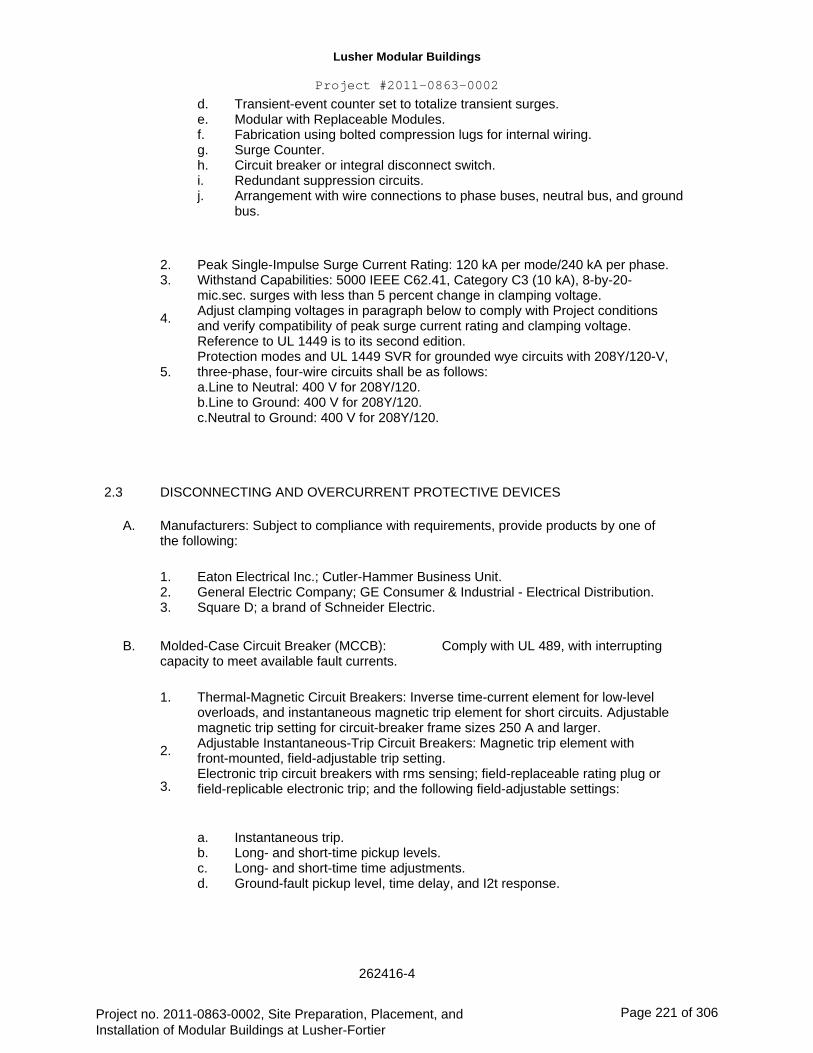
Lusher Modular Buildings
Project #2011-0863-0002
d. e. f. g. h. i. j.
Transient-event counter set to totalize transient surges. Modular with Replaceable Modules. Fabrication using bolted compression lugs for internal wiring. Surge Counter. Circuit breaker or integral disconnect switch. Redundant suppression circuits. Arrangement with wire connections to phase buses, neutral bus, and ground bus.
2. 3.
4.
5.
Peak Single-Impulse Surge Current Rating: 120 kA per mode/240 kA per phase. Withstand Capabilities: 5000 IEEE C62.41, Category C3 (10 kA), 8-by-20- mic.sec. surges with less than 5 percent change in clamping voltage. Adjust clamping voltages in paragraph below to comply with Project conditions and verify compatibility of peak surge current rating and clamping voltage. Reference to UL 1449 is to its second edition. Protection modes and UL 1449 SVR for grounded wye circuits with 208Y/120-V, three-phase, four-wire circuits shall be as follows: a.Line to Neutral: 400 V for 208Y/120. b.Line to Ground: 400 V for 208Y/120. c.Neutral to Ground: 400 V for 208Y/120.
2.3
A.
DISCONNECTING AND OVERCURRENT PROTECTIVE DEVICES
Manufacturers: Subject to compliance with requirements, provide products by one of the following:
1. 2. 3.
Eaton Electrical Inc.; Cutler-Hammer Business Unit. General Electric Company; GE Consumer & Industrial - Electrical Distribution. Square D; a brand of Schneider Electric.
Comply with UL 489, with interrupting B. Molded-Case Circuit Breaker (MCCB): capacity to meet available fault currents.
1.
2.
3.
Thermal-Magnetic Circuit Breakers: Inverse time-current element for low-level overloads, and instantaneous magnetic trip element for short circuits. Adjustable magnetic trip setting for circuit-breaker frame sizes 250 A and larger. Adjustable Instantaneous-Trip Circuit Breakers: Magnetic trip element with front-mounted, field-adjustable trip setting. Electronic trip circuit breakers with rms sensing; field-replaceable rating plug or field-replicable electronic trip; and the following field-adjustable settings:
a. b. c. d.
Instantaneous trip. Long- and short-time pickup levels. Long- and short-time time adjustments. Ground-fault pickup level, time delay, and I2t response.
262416-4
Project no. 2011-0863-0002, Site Preparation, Placement, and Installation of Modular Buildings at Lusher-Fortier
Page 221 of 306
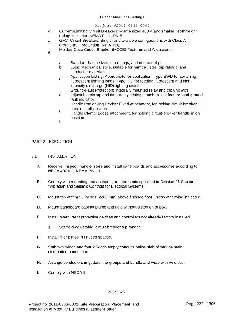
Lusher Modular Buildings
Project #2011-0863-0002
4.
5.
6.
Current-Limiting Circuit Breakers: Frame sizes 400 A and smaller; let-through ratings less than NEMA FU 1, RK-5. GFCI Circuit Breakers: Single- and two-pole configurations with Class A ground-fault protection (6-mA trip). Molded-Case Circuit-Breaker (MCCB) Features and Accessories:
a. b.
c.
Standard frame sizes, trip ratings, and number of poles. Lugs: Mechanical style, suitable for number, size, trip ratings, and conductor materials. Application Listing: Appropriate for application; Type SWD for switching fluorescent lighting loads; Type HID for feeding fluorescent and high- intensity discharge (HID) lighting circuits. Ground-Fault Protection: Integrally mounted relay and trip unit with adjustable pickup and time-delay settings, push-to-test feature, and ground- fault indicator. Handle Padlocking Device: Fixed attachment, for locking circuit-breaker handle in off position. Handle Clamp: Loose attachment, for holding circuit-breaker handle in on position.
d.
e.
f.
PART 3 - EXECUTION
3.1
A.
B.
C.
D.
E.
INSTALLATION
Receive, inspect, handle, store and install panelboards and accessories according to NECA 407 and NEMA PB 1.1.
Comply with mounting and anchoring requirements specified in Division 26 Section "Vibration and Seismic Controls for Electrical Systems."
Mount top of trim 90 inches (2286 mm) above finished floor unless otherwise indicated.
Mount panelboard cabinet plumb and rigid without distortion of box.
Install overcurrent protective devices and controllers not already factory installed.
1.
F.
G.
H.
I.
Set field-adjustable, circuit-breaker trip ranges.
Install filler plates in unused spaces.
Stub two 4-inch and four 2.5-inch empty conduits below slab of service main distribution panel board.
Arrange conductors in gutters into groups and bundle and wrap with wire ties.
Comply with NECA 1.
262416-5
Project no. 2011-0863-0002, Site Preparation, Placement, and Installation of Modular Buildings at Lusher-Fortier
Page 222 of 306
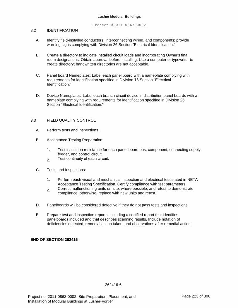
Lusher Modular Buildings
Project #2011-0863-0002
3.2
A.
B.
IDENTIFICATION
Identify field-installed conductors, interconnecting wiring, and components; provide warning signs complying with Division 26 Section "Electrical Identification."
Create a directory to indicate installed circuit loads and incorporating Owner's final room designations. Obtain approval before installing. Use a computer or typewriter to create directory; handwritten directories are not acceptable.
Panel board Nameplates: Label each panel board with a nameplate complying with requirements for identification specified in Division 16 Section "Electrical Identification."
Device Nameplates: Label each branch circuit device in distribution panel boards with a nameplate complying with requirements for identification specified in Division 26 Section "Electrical Identification."
FIELD QUALITY CONTROL
Perform tests and inspections.
Acceptance Testing Preparation:
1.
2.
Test insulation resistance for each panel board bus, component, connecting supply, feeder, and control circuit. Test continuity of each circuit.
C.
D.
3.3
A.
B.
C. Tests and Inspections:
1.
2.
Perform each visual and mechanical inspection and electrical test stated in NETA Acceptance Testing Specification. Certify compliance with test parameters. Correct malfunctioning units on-site, where possible, and retest to demonstrate compliance; otherwise, replace with new units and retest.
D.
E.
Panelboards will be considered defective if they do not pass tests and inspections.
Prepare test and inspection reports, including a certified report that identifies panelboards included and that describes scanning results. Include notation of deficiencies detected, remedial action taken, and observations after remedial action.
END OF SECTION 262416
262416-6
Project no. 2011-0863-0002, Site Preparation, Placement, and Installation of Modular Buildings at Lusher-Fortier
Page 223 of 306
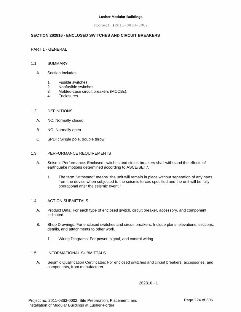
Lusher Modular Buildings
Project #2011-0863-0002 SECTION 262816 - ENCLOSED SWITCHES AND CIRCUIT BREAKERS
PART 1 - GENERAL
1.1
A.
SUMMARY
Section Includes:
1. 2. 3. 4.
1.2
A.
B.
C.
1.3
A.
Fusible switches. Nonfusible switches. Molded-case circuit breakers (MCCBs). Enclosures.
DEFINITIONS
NC: Normally closed.
NO: Normally open.
SPDT: Single pole, double throw.
PERFORMANCE REQUIREMENTS
Seismic Performance: Enclosed switches and circuit breakers shall withstand the effects of earthquake motions determined according to ASCE/SEI 7.
1. The term "withstand" means "the unit will remain in place without separation of any parts from the device when subjected to the seismic forces specified and the unit will be fully operational after the seismic event."
1.4
A.
B.
ACTION SUBMITTALS
Product Data: For each type of enclosed switch, circuit breaker, accessory, and component indicated.
Shop Drawings: For enclosed switches and circuit breakers. Include plans, elevations, sections, details, and attachments to other work.
1. Wiring Diagrams: For power, signal, and control wiring.
1.5
A.
INFORMATIONAL SUBMITTALS
Seismic Qualification Certificates: For enclosed switches and circuit breakers, accessories, and components, from manufacturer.
262816 - 1
Project no. 2011-0863-0002, Site Preparation, Placement, and Installation of Modular Buildings at Lusher-Fortier
Page 224 of 306
Lusher Modular Buildings
Project #2011-0863-0002
B.
1.6
A.
1.7
A.
B.
Field quality-control reports.
CLOSEOUT SUBMITTALS
Operation and maintenance data.
QUALITY ASSURANCE
Electrical Components, Devices, and Accessories: Listed and labeled as defined in NFPA 70, by a qualified testing agency, and marked for intended location and application.
Comply with NFPA 70.
PART 2 - PRODUCTS
2.1
A.
FUSIBLE SWITCHES
Manufacturers: Subject to compliance with requirements, provide products by one of the following:
1. 2. 3. 4.
B.
Eaton Electrical Inc.; Cutler-Hammer Business Unit. General Electric Company; GE Consumer & Industrial - Electrical Distribution. Siemens Energy & Automation, Inc. Square D; a brand of Schneider Electric.
Type HD, Heavy Duty, Single Throw, 600-V ac, 1200 A and Smaller: UL 98 and NEMA KS 1, horsepower rated, with clips or bolt pads to accommodate indicated fuses, lockable handle with capability to accept three padlocks, and interlocked with cover in closed position.
Accessories:
1.
2.
3.
4. 5.
Equipment Ground Kit: Internally mounted and labeled for copper and aluminum ground conductors. Neutral Kit: Internally mounted; insulated, capable of being grounded and bonded; labeled for copper and aluminum neutral conductors. Class R Fuse Kit: Provides rejection of other fuse types when Class R fuses are specified. Lugs: Suitable for number, size, and conductor material. Service-Rated Switches: Labeled for use as service equipment.
C.
2.2
A.
NONFUSIBLE SWITCHES
Manufacturers: Subject to compliance with requirements, provide products by one of the following:
1. Eaton Electrical Inc.; Cutler-Hammer Business Unit.
262816 - 2
Project no. 2011-0863-0002, Site Preparation, Placement, and Installation of Modular Buildings at Lusher-Fortier
Page 225 of 306

Lusher Modular Buildings
Project #2011-0863-0002
2. 3. 4.
B.
General Electric Company; GE Consumer & Industrial - Electrical Distribution. Siemens Energy & Automation, Inc. Square D; a brand of Schneider Electric.
Type HD, Heavy Duty, Single Throw, 600-V ac, 1200 A and Smaller: UL 98 and NEMA KS 1, horsepower rated, lockable handle with capability to accept three padlocks, and interlocked with cover in closed position.
Accessories:
1.
2.
3.
Equipment Ground Kit: Internally mounted and labeled for copper and aluminum ground conductors. Neutral Kit: Internally mounted; insulated, capable of being grounded and bonded; labeled for copper and aluminum neutral conductors. Lugs: Suitable for number, size, and conductor material.
C.
2.3
A.
MOLDED-CASE CIRCUIT BREAKERS
Manufacturers: Subject to compliance with requirements, provide products by one of the following:
1. 2. 3. 4.
B.
C.
Eaton Electrical Inc.; Cutler-Hammer Business Unit. General Electric Company; GE Consumer & Industrial - Electrical Distribution. Siemens Energy & Automation, Inc. Square D; a brand of Schneider Electric.
General Requirements:Comply with UL 489, NEMA AB 1, and NEMA AB 3, with interrupting capacity to comply with available fault currents.
Thermal-Magnetic Circuit Breakers: Inverse time-current element for low-level overloads and instantaneous magnetic trip element for short circuits. Adjustable magnetic trip setting for circuit-breaker frame sizes 250 A and larger.
Electronic Trip Circuit Breakers: Field-replaceable rating plug, rms sensing, with the following field-adjustable settings:
1. 2. 3. 4.
Instantaneous trip. Long- and short-time pickup levels. Long- and short-time time adjustments. Ground-fault pickup level, time delay, and I2t response.
D.
E.
F.
Current-Limiting Circuit Breakers: Frame sizes 400 A and smaller, and let-through ratings less than NEMA FU 1, RK-5.
Features and Accessories:
1. 2.
Standard frame sizes, trip ratings, and number of poles. Lugs: Suitable for number, size, trip ratings, and conductor material.
262816 - 3
Project no. 2011-0863-0002, Site Preparation, Placement, and Installation of Modular Buildings at Lusher-Fortier
Page 226 of 306

Lusher Modular Buildings
Project #2011-0863-0002
3.
4.
5. 6.
7.
2.4
A.
Application Listing: Appropriate for application; Type SWD for switching fluorescent lighting loads; Type HID for feeding fluorescent and high-intensity discharge lighting circuits. Ground-Fault Protection: Comply with UL 1053; integrally mounted, self-powered type with mechanical ground-fault indicator; relay with adjustable pickup and time-delay settings, push-to-test feature, internal memory, and shunt trip unit; and three-phase, zero- sequence current transformer/sensor. Shunt Trip: Trip coil energized from separate circuit, with coil-clearing contact. Auxiliary Contacts: One SPDT switch with "a" and "b" contacts; "a" contacts mimic circuit-breaker contacts, "b" contacts operate in reverse of circuit-breaker contacts. Alarm Switch: One NO contact that operates only when circuit breaker has tripped.
ENCLOSURES
Enclosed Switches and Circuit Breakers: NEMA AB 1, NEMA KS 1, NEMA 250, and UL 50, to comply with environmental conditions at installed location.
1. 2. 3. 4. 5.
Indoor, Dry and Clean Locations: NEMA 250, Type 1. Outdoor Locations: NEMA 250, Type 3R. Wash-Down Areas: NEMA 250, Type 4X, stainless steel. Other Wet or Damp, Indoor Locations: NEMA 250, Type 4. Indoor Locations Subject to Dust, Falling Dirt, and Dripping Noncorrosive Liquids: NEMA 250, Type 12.
PART 3 - EXECUTION
3.1
A.
B.
C.
D.
E.
3.2
A.
INSTALLATION
Install individual wall-mounted switches and circuit breakers with tops at uniform height unless otherwise indicated.
Comply with mounting and anchoring requirements specified in Division 26 Section "Vibration and Seismic Controls for Electrical Systems."
Temporary Lifting Provisions: Remove temporary lifting eyes, channels, and brackets and temporary blocking of moving parts from enclosures and components.
Install fuses in fusible devices.
Comply with NECA 1.
IDENTIFICATION
Comply with requirements in Division 26 Section "Identification for Electrical Systems."
1.
2.
Identify field-installed conductors, interconnecting wiring, and components; provide warning signs. Label each enclosure with engraved metal or laminated-plastic nameplate.
262816 - 4
Project no. 2011-0863-0002, Site Preparation, Placement, and Installation of Modular Buildings at Lusher-Fortier
Page 227 of 306

Lusher Modular Buildings
Project #2011-0863-0002
3.3
A.
B.
FIELD QUALITY CONTROL
Perform tests and inspections.
Acceptance Testing Preparation:
1.
2.
C.
Test insulation resistance for each enclosed switch and circuit breaker, component, connecting supply, feeder, and control circuit. Test continuity of each circuit.
Tests and Inspections:
1.
2.
Perform each visual and mechanical inspection and electrical test stated in NETA Acceptance Testing Specification. Certify compliance with test parameters. Correct malfunctioning units on-site, where possible, and retest to demonstrate compliance; otherwise, replace with new units and retest.
D.
E.
Enclosed switches and circuit breakers will be considered defective if they do not pass tests and inspections.
Prepare test and inspection reports, including a certified report that identifies enclosed switches and circuit breakers and that describes scanning results. Include notation of deficiencies detected, remedial action taken, and observations after remedial action.
END OF SECTION 262816
262816 - 5
Project no. 2011-0863-0002, Site Preparation, Placement, and Installation of Modular Buildings at Lusher-Fortier
Page 228 of 306
Lusher Modular Buildings
Project #2011-0863-0002
SECTION 270528
TELEPHONE SYSTEM
PART 1 - GENERAL
1.1
A.
SUMMARY
The work of this section consists of providing labor, materials, tools, appliances and miscellaneous accessories associated with the telephone raceway system as described herein and as indicated on the Drawings.
1.2
A.
B.
C.
RELATED SECTIONS
Drawings.
Division 01 - Specification Sections.
Section 260000 - Basic Electrical Requirements.
PART 2 - PRODUCTS
2. 1
A.
B.
MATERIALS AND COMPONENTS
Raceways: Refer to Section 260533.
Wall-Type Telephone Outlets: Provide 4" x 11/16" square x 2-1/8" box, with single gang cover.
PART 3 - EXECUTION
A. Provide all conduit, outlets, supports, fittings, covers, and/or other material as required, ready for installation of conductors by the local Telephone Company.
No more than two 90 degree bends in a run will be permissible without the insertion of pull boxes.
A "fish wire" shall be left in all empty conduits. Installation of conductors, instruments, and connections will be made by the Owner.
Telephone outlets in dry wall partitions or plaster walls shall have single gang plaster covers and single gang device covers with a bushed opening, to match switch and receptacle plates.
Furnish and install one (1) No. 6 THW copper ground wire in 1/2" conduit from main
270528 - 1
B.
C.
D.
E.
Project no. 2011-0863-0002, Site Preparation, Placement, and Installation of Modular Buildings at Lusher-Fortier
Page 229 of 306
Lusher Modular Buildings
Project #2011-0863-0002
telephone backboard to nearest main grounding point such as water main or building ground pad.
F. From the fire alarm control panel, provide a 3/4" conduit with nylon pull cord to the main telephone backboard as located on the drawings.
END OF SECTION 270528
270528 - 2
Project no. 2011-0863-0002, Site Preparation, Placement, and Installation of Modular Buildings at Lusher-Fortier
Page 230 of 306
Lusher Modular Buildings
Project #2011-0863-0002
SECTION 283111
FIRE ALARM SYSTEMS
PART 1 -
1.01
GENERAL
SUMMARY
A. The work of this section consists of providing labor, materials, tools, appliances and miscellaneous accessories associated with the installation of a complete and properly operating addressable Fire Alarm System. The system shall include, but not limited to: Booster power supplies, Automatic and Manually activated alarm Initiating and Indicating Peripheral Devices and Appliances, conduit, wire, etc.
Scope:
The work of the fire alarm system supplier shall include but not be limited to the following:
1.
2.
3.
4.
5.
6.
7.
8.
9.
Furnish a complete and operational system in compliance with all applicable codes.
Furnish complete system drawings including plan views on Architectural backgrounds, point to point connection diagrams, riser diagrams, etc.
Prepare complete submittal package for application to State Fire Marshal, including application fee and variance request fees as required.
Provide necessary field supervision, technical support, etc. to contractor to assure a proper installation.
Perform all necessary programming to assure proper system operation.
Perform a total operational test after completion of installation.
Provide factory trained technicians for all system tests to be witnessed by Engineer, Owner, Fire Marshal, etc.
Provide factory trained technicians for Owner orientation and training.
Provide four complete sets of final documentation including drawings, brochures, maintenance manuals, letter of certification, etc. in bound type loose leaf binder.
Provide one year parts and labor warranty including one complete reprogramming of system starting from the date of the project acceptance.
Provide a separate proposal for annual maintenance and testing contract.
Successful fire alarm system supplier and installer shall coordinate the fire alarm system monitoring service with Sonitrol. Contact Ed Hilderbrand at 504-837-7144 for system requirements, equipment, hardware, fees, etc. prior to submitting bid. Provide two (2) dedicated phone lines in ¾” EMT raceway as required by Sonitrol. All Sonitrol material, hardware, labor, fees,
B.
10.
11.
12.
283111-1
Project no. 2011-0863-0002, Site Preparation, Placement, and Installation of Modular Buildings at Lusher-Fortier
Page 231 of 306
Lusher Modular Buildings
Project #2011-0863-0002
etc. shall be inclusive of the fire alarm system cost. Sonitrol monitoring fees shall be paid by owner.
13. All existing devices removed shall be quantified, recorded, and turned over to owner at date of final inspection.
1.02 RELATED SECTIONS
A.
B.
C.
D.
Drawings
Division 01 - Specification Section.
Section 260000 - Basic Electrical Requirements.
Section 270528 – Telephone System
1.03 STANDARDS
A.
B.
Prior to ordering materials, installation of raceway system shall be coordinated with Architect/Engineer for exact system layout and conduit requirements.
All fire alarm wiring shall be installed in open FPL cable unless otherwise noted. The contractor shall be responsible for the supply and installation of the conduit, wiring, junction boxes, and terminal cabinets in accordance with the manufacturers' recommendations. All conduit shall be concealed in finished areas, coordinate with Division 1.
1.04 REFERENCES
The equipment and installation shall comply with the current provisions of the following standards:
National Electric Code, Article 760.
National Fire Protection Association Standards:
NFPA 72
NFPA 90A
NFPA 101
National Fire Alarm Code
Standard for the Installation of Air Conditioning and Ventilation Systems
Life Safety Code
Local and State Building Codes.
Local Authorities Having Jurisdiction.
ULC, CSFM, BSA, City of Chicago High Rise Code
Underwriters Laboratories Inc.
283111-2
Project no. 2011-0863-0002, Site Preparation, Placement, and Installation of Modular Buildings at Lusher-Fortier
Page 232 of 306

Lusher Modular Buildings
Project #2011-0863-0002 The system and all components shall be listed by Underwriters Laboratories Inc. for use
in fire protective signaling system under the following standards as applicable:
UL 864/UOJZ, APOU Systems.
UL 268
UL 268A
UL 521
UL 228
UL 464
UL 1638
UL 38
UL 346
UL 1971
UL 1481
UL 1711
Smoke Detectors for Fire Protective Signaling Systems.
Smoke Detectors for Duct Applications.
Heat Detectors for Fire Protective Signaling Systems.
Door Holders for Fire Protective Signaling Systems.
Audible Signaling Appliances.
Visual Signaling Appliances.
Manually Activated Signaling Boxes.
Waterflow Indicators for Fire Protective Signaling Systems.
Standard for Signaling Devices for the Hearing Impaired
Power Supplies for Fire Protective Signaling Systems.
Amplifiers for Fire Protective Signaling Systems.
Control Units for Fire Protective Signaling
Americans with Disabilities Act (ADA)
1.05 QUALIFICATIONS
A. The installing General Contractor and/or Sub-Contractor shall provide proof of their qualifications as Factory Authorization and Factory Training for the product(s) specified herein. These qualification credentials shall not be more than two years old, to ensure up-to-date product and application knowledge on the part of installing fire alarm systems distributor.
The installing General Contractor and/or Sub-Contractor shall provide documentation of past projects similar in nature to system described by the referenced drawings and specifications. Provide a list of five (5) projects total: three (3) of which must be similar in nature the remaining two (2) projects must be within the past eight (5) years.
B.
1.06 SYSTEM DESCRIPTION
A. The Fire Alarm / Life Safety System supplied under this specification shall be compatible with and connect to the existing system. All Control Panel Assemblies and connected Field Appliances shall be both designed and manufactured by the same company, and shall be tested and cross-listed as compatible to ensure that a fully functioning Life Safety System is designed and installed.
283111-3
Project no. 2011-0863-0002, Site Preparation, Placement, and Installation of Modular Buildings at Lusher-Fortier
Page 233 of 306

Lusher Modular Buildings
Project #2011-0863-0002
1.07 SERVICE
A. The equipment manufacturer shall be represented by a local service organization. Technicians shall be factory trained by the manufacturer to install, test, service and maintain the system herein specified.
The fire alarm/life safety system supplied must be supervised from a listed remote monitoring station agency. Contractor is responsible for all equipment, components, and fees required to conform with the above. Contractor shall coordinate selection of remote monitoring station agency with owner representative.
B.
1.08 SUBMITTALS
Refer to Division 1 for minimal submittal requirements. The following requirements are in addition to the requirements of Division 1.
A. SHOP DRAWINGS
1. Submittal data for the Fire Alarm System shall consist of shop drawings and/or catalog cuts highlighted indicating the type, size, rating, style, catalog number, manufacturers' names, photos, and/or catalog data sheets for all items proposed to meet these specifications. Submittals shall provide the technical data necessary to evaluate the equipment including cabinet dimensions, fabrication materials and other descriptive data necessary to fully describe the equipment proposed. All drawings shall be in AutoCad 2007 format. All shop drawing submitted by the contractor to the engineer for approval and release to the state fire marshal's office shall comply with the State of Louisiana Department of Public Safety and Corrections Office of the State Fire Marshal Code Enforcement and Building Safety fire alarm review checklist requirements. The contractor shall be responsible for satisfying the above requirements.
A one line control wiring diagram, and equipment layout (all areas) shall be included with the submittal material including all alarm initiating devices, annunciation devices and control equipment. This diagram is to indicate the circuit loops, device addresses, and fire zoning, of the building, conduit sizes and wiring requirements. Also typical alarm, annunciation and control circuit diagram shall be submitted.
Provide battery calculations, shop drawings etc. for submittal to Fire Marshal's Office for approval. Pay for fees.
Refer to front end document and Division 1 for minimum product substitution requirements.
2.
3.
B. SUBSTITUTIONS
1.
283111-4
Project no. 2011-0863-0002, Site Preparation, Placement, and Installation of Modular Buildings at Lusher-Fortier
Page 234 of 306

Lusher Modular Buildings
Project #2011-0863-0002 2. Submission of product purported to be equal to those specified herein will
be considered as possible substitutes only when all of the following requirements have been met:
a. Any deviation from the equipment, operations, methods, design or other criteria specified herein must be submitted in detail to the Specifying Architect or Engineer a minimum of 7 working days prior to the scheduled submission of bids. Each deviation from the operation detailed in these specifications must be documented in detail, including Page Number and Section Number that lists the system function for which the substitution is being proposed.
A complete list of such substituted products, with three (3) copies of working drawings for each, shall be submitted to and be approved by the architect and/or consulting engineer, not less than seven (7) calendar days prior to the scheduled date for opening bids.
The contractor or substitute bidder shall functionally demonstrate that the proposed substituted products are, in fact, equal in quality and performance to those specified herein, and that they are compatible with and listed for connection to the existing fire alarm system. Because the decision to specify the Life Safety System(s) and Equipment detailed herein was made by an Architect and/or Consulting Engineer on behalf of their client(s) (the Building Owners), such evidence of the applicability of any substitute materials must be submitted to, and accepted by, the Architect and/or Consulting Engineer, not less than seven (7) calendar days prior to the scheduled date for opening bids for this project. Substitute equipment will be accepted only on the discretion of the Architect and/or Consulting Engineer on behalf of the Building Owner.
b.
c.
C. CLOSE-OUT SUBMITTALS
Four (4) copies of the following Manual shall be delivered to the Building Owner's representative at the time of system acceptance. The close out submittals shall include:
1.
2.
Operating manuals, brochures, drawings, letter of certification, etc. covering the installed Life Safety System.
Point to Point diagrams of the entire Life Safety System as installed. This shall include all connected Smoke Detectors and addressable field modules. All drawings shall be provided in AutoCAD 2007 format and supplied in standard .dwg format. A system generated point to point diagram is required to ensure accuracy.
283111-5
Project no. 2011-0863-0002, Site Preparation, Placement, and Installation of Modular Buildings at Lusher-Fortier
Page 235 of 306
Lusher Modular Buildings
Project #2011-0863-0002 3. The application program listing for the system as installed at the time of
acceptance by the building owner and/or Local AHJ (CD and Hard copy printout).
Name, address and telephone of the authorized factory representative.
All drawings must reflect device address and programmed characteristics as verified in the presence of the engineer and/or the end user unless device addressing is electronically generated, and graphically printed.
“As-Built” riser and wiring diagrams reflecting each individual loop indicating number of devices on each loop, each programmed device characteristic including detector type, base type, serial number, sensitivity setting and wire configurations will be provided to the Architect/Engineer, based on the information gathered during the verification process. No T taps allowed.
The contractor shall submit a fresh, clearly marked set of construction documents in additions to a System Generated device map, subject to Architect/Engineer approval, to serve as an “as-built” drawing to be provided to the Local AHJ and the Building Owners’ Representative.
A copy of the manufacturers’ warranty shall be provided with close-out documentation and included with the operation and installation manuals.
4.
5.
6.
7.
8.
1.09 ALARM SEQUENCE
The system alarm operation subsequent to the alarm activation of any manual station, automatic detection device, or future sprinkler flow switch is to be as follows:
1.
2.
3.
4.
5.
All audible alarm indicating appliances shall sound a digitized tone until silenced by the alarm silence switch at the control panel.
Xenon Strobes shall be syncronous type and display a continuous pattern until System is reset.
Alarm horns and strobes shall operate selectively by zone(s) or area.
All doors normally held open by door control devices shall release.
A supervised signal to notify the local fire department and/or an approved central station is to be activated. To accommodate and facilitate job site changes the type of "city connection circuit" is to be on site configurable to provide either a "reverse polarity", "local energy," "shunt" or dry contact connection.
The mechanical controls shall activate the air handling systems per life safety specification, NFPA 101.
6.
283111-6
Project no. 2011-0863-0002, Site Preparation, Placement, and Installation of Modular Buildings at Lusher-Fortier
Page 236 of 306
Lusher Modular Buildings
Project #2011-0863-0002 1.10 INTERFACING WITH OTHER EQUIPMENT
A. HVAC systems shall have duct smoke detectors with remote test/reset stations provided under this section. Contractor shall provide the necessary number of duct smoke detectors in the proper location as required by code. Interconnect these alarm devices as described above to the fire alarm system using interface monitor module.
Duct detectors shall be installed by a qualified licensed HVAC system mechanical contractor in locations as determined by licensed fire alarm contractor in accordance with NFPA 72, 90A, and 101 codes.
Contractor shall interconnect these smoke detector system alarm devices as described above to the fire alarm system.
Tamper / Flow switches as required.
All initiation devices shall be addressable identified individually by type and location message. Initiating devices shall include all area type smoke detectors, duct detectors.
PRODUCTS
All equipment and components shall be new, and the manufacturer's current model and manufactured in 2010 or later. The materials, appliances, equipment and devices shall be tested and listed by a nationally recognized approvals agency for use as part of a protective signaling system, meeting the National Fire Alarm Code.
All equipment and components shall be installed in strict compliance with manufacturers' recommendations. Consult the manufacturer's installation manuals for all wiring diagrams, schematics, physical equipment sizes, etc., before beginning system installation.
All equipment shall be attached to walls and ceiling/floor assemblies and shall be held firmly in place (e.g., detectors shall not be supported solely by suspended ceilings). Fasteners and supports shall be adequate to support the required load.
Conduit:
1.
2.
Conduit shall be in accordance with The National Electrical Code (NEC), local and state requirements.
Where required, all wiring shall be installed in conduit or raceway. Conduit fill shall not exceed 40 percent of interior cross sectional area where three or more cables are contained within a single conduit.
B.
C.
D.
1.11
A.
ZONING
PART 2 -
2.01
A.
EQUIPMENT AND MATERIAL, GENERAL:
B.
C.
2.02 CONDUIT AND WIRE:
A.
283111-7
Project no. 2011-0863-0002, Site Preparation, Placement, and Installation of Modular Buildings at Lusher-Fortier
Page 237 of 306

Lusher Modular Buildings
Project #2011-0863-0002 3. Cable must be separated from any open conductors of power, or Class 1
circuits, and shall not be placed in any conduit, junction box or raceway containing these conductors, per NEC Article 760.
Wiring for 24 volt DC control, alarm notification, emergency communication and similar power-limited auxiliary functions may be run in the same conduit as initiating and signaling line circuits. All circuits shall be provided with transient suppression devices and the system shall be designed to permit simultaneous operation of all circuits without interference or loss of signals.
Conduit shall not enter the fire alarm control panel, or any other remotely mounted control panel equipment or backboxes, except where conduit entry is specified by the FACP manufacturer.
Conduit shall be 3/4-inch (19.1 mm) minimum.
All fire alarm system wiring shall be new.
Wiring shall be in accordance with local, state and national codes (e.g., NEC Article 760) and as recommended by the manufacturer of the fire alarm system. Number and size of conductors shall be as recommended by the fire alarm system manufacturer, but not less than 18 AWG (1.02 mm) for Initiating Device Circuits and Signaling Line Circuits, and 14 AWG (1.63 mm) for Notification Appliance Circuits.
All wire and cable shall be listed and/or approved by a recognized testing agency for use with a protective signaling system.
Wire and cable not installed in conduit shall have a fire resistance rating suitable for the installation as indicated in NFPA 70 (e.g., FPLR).
Wiring used for the multiplex communication circuit (SLC) shall be twisted and unshielded and support a minimum wiring distance of 12,500 feet. The design of the system shall permit use of IDC and NAC wiring in the same conduit with the SLC communication circuit.
All field wiring shall be electrically supervised for open circuit and ground fault.
4.
5.
6.
B. Wire:
1.
2.
3.
4.
5.
6.
C.
D.
Terminal Boxes, Junction Boxes and Cabinets:
All boxes and cabinets shall be UL listed for their use and purpose.
Initiating circuits shall be arranged to serve like categories (manual, smoke, waterflow). Mixed category circuitry shall not be permitted except on signaling line circuits connected to intelligent reporting devices.
The fire alarm control panel and booster power supplies shall each be connected to a separate dedicated branch circuit, maximum 20 amperes. This circuit shall be
E.
283111-8
Project no. 2011-0863-0002, Site Preparation, Placement, and Installation of Modular Buildings at Lusher-Fortier
Page 238 of 306
Lusher Modular Buildings
Project #2011-0863-0002 labeled at the main power distribution panel as FIRE ALARM. Fire alarm control
panel primary power wiring shall be 12 AWG. The control panel cabinet shall be grounded securely to either a cold water pipe or grounding rod.
2.03 MAIN FIRE ALARM CONTROL PANEL
A. Main FACP is an existing panel manufactured by GE-Edwards System Technology, and is located in the existing Communications Building. The CPU shall communicate with and control the following types of equipment used to make up the system: intelligent addressable smoke and thermal (heat) detectors, addressable modules, printer, annunciators, and other system controlled devices.
Furnish additional cards/modules as required to interface with the devices being furnished under this contract.
B.
2.04 SYSTEM COMPONENTS - ADDRESSABLE DEVICES
A. Addressable Devices - General
1. Addressable devices shall use simple to install and maintain decade, decimal address switches. Devices shall be capable of being set to an address in a range of 001 to 159.
Addressable devices, which use a binary-coded address setting method, such as a DIP-switch, are not an allowable substitute.
Detectors shall be intelligent (analog) and addressable, and shall connect with two wires to the fire alarm control panel Signaling Line Circuits.
Addressable smoke and thermal detectors shall provide dual alarm and power/polling LEDs. Both LEDs shall flash green under normal conditions, indicating that the detector is operational and in regular communication with the control panel, and both LEDs shall be placed into steady red illumination by the control panel, indicating that an alarm condition has been detected. If required, the LED flash shall have the ability to be removed from the system program. An output connection shall also be provided in the base to connect an external remote alarm LED.
The fire alarm control panel shall permit detector sensitivity adjustment through field programming of the system. The panel on a time-of-day basis shall automatically adjust sensitivity.
Using software in the FACP, detectors shall automatically compensate for dust accumulation and other slow environmental changes that may affect their performance. The detectors shall be listed by UL as meeting the calibrated sensitivity test requirements of NFPA Standard 72, Chapter 7.
2.
3.
4.
5.
6.
283111-9
Project no. 2011-0863-0002, Site Preparation, Placement, and Installation of Modular Buildings at Lusher-Fortier
Page 239 of 306
Lusher Modular Buildings
Project #2011-0863-0002 7. The detectors shall be ceiling-mount and shall include a separate twist-
lock base with tamper proof feature. Bases shall include a sounder base with a built-in (local) sounder rated at 85 DBA minimum, a relay base and an isolator base designed for Style 7 applications.
The detectors shall provide a test means whereby they will simulate an alarm condition and report that condition to the control panel. Such a test may be initiated at the detector itself (by activating a magnetic switch) or initiated remotely on command from the control panel.
Detectors shall also store an internal identifying type code that the control panel shall use to identify the type of device (ION, PHOTO, THERMAL).
Detectors will operate in an analog fashion, where the detector simply measures its designed environment variable and transmits an analog value to the FACP based on real-time measured values. The FACP software, not the detector, shall make the alarm/normal decision, thereby allowing the sensitivity of each detector to be set in the FACP program and allowing the system operator to view the current analog value of each detector.
Addressable devices shall store an internal identifying code that the control panel shall use to identify the type of device.
A magnetic test switch shall be provided to test detectors and modules. Detectors shall report an indication of an analog value reaching 100% of the alarm threshold.
Addressable modules shall mount in a 4-inch square (101.6 mm square), 2-1/8 inch (54 mm) deep electrical box. An optional surface mount Lexan enclosure shall be available.
8.
9.
10.
11.
12.
14.
B. Addressable Manual Fire Alarm Box (manual station)
1. Addressable manual fire alarm boxes shall, on command from the control panel, send data to the panel representing the state of the manual switch and the addressable communication module status. They shall use a key operated test-reset lock, and shall be designed so that after actual emergency operation, they cannot be restored to normal use except by the use of a key.
All operated stations shall have a positive, visual indication of operation and utilize a key type reset.
Manual fire alarm boxes shall be constructed of Lexan with clearly visible operating instructions provided on the cover. The word FIRE shall appear on the front of the stations in raised letters, 1.75 inches (44 mm) or larger.
2.
3.
283111-10
Project no. 2011-0863-0002, Site Preparation, Placement, and Installation of Modular Buildings at Lusher-Fortier
Page 240 of 306
Lusher Modular Buildings
Project #2011-0863-0002 C. Intelligent Photoelectric Smoke Detector
1. The detectors shall use the photoelectric (light-scattering) principal to measure smoke density and shall, on command from the control panel, send data to the panel representing the analog level of smoke density.
Thermal detectors shall be intelligent addressable devices rated at 135 degrees Fahrenheit (58 degrees Celsius) and have a rate-of-rise element rated at 15 degrees F (9.4 degrees C) per minute. It shall connect via two wires to the fire alarm control panel signaling line circuit.
The smoke detector housing shall accommodate either an intelligent ionization detector or an intelligent photoelectric detector, of that provides continuous analog monitoring and alarm verification from the panel.
When sufficient smoke is sensed, an alarm signal is initiated at the FACP, and appropriate action taken to change over air handling systems to help prevent the rapid distribution of toxic smoke and fire gases throughout the areas served by the duct system.
Addressable monitor modules shall be provided to connect one supervised IDC zone of conventional alarm initiating devices (any N.O. dry contact device) to one of the fire alarm control panel SLCs.
The IDC zone shall be suitable for Style D or Style B operation. An LED shall be provided that shall flash under normal conditions, indicating that the monitor module is operational and in regular communication with the control panel.
For difficult to reach areas, the monitor module shall be available in a miniature package and shall be no larger than 2-3/4 inch (70 mm) x 1-1/4 inch (31.7 mm) x 1/2 inch (12.7 mm). This version need not include Style D or an LED.
Addressable Relay Modules shall be available for HVAC control and other building functions. The relay shall be form C and rated for a minimum of 2.0 Amps resistive or 1.0 Amps inductive. The relay coil shall be magnetically latched to reduce wiring connection requirements, and to insure that 100% of all auxiliary relay or NACs may be energized at the same time on the same pair of wires.
E. Intelligent Thermal Detectors
1.
E. Intelligent Duct Smoke Detector
1.
2.
F. Addressable Dry Contact Monitor Module
1.
2.
3.
G. Addressable Relay Module
1.
283111-11
Project no. 2011-0863-0002, Site Preparation, Placement, and Installation of Modular Buildings at Lusher-Fortier
Page 241 of 306
Lusher Modular Buildings
Project #2011-0863-0002 2.06 BATTERIES:
A.
B.
C.
The battery shall have sufficient capacity to power the fire alarm system for not less than sixty hours plus 15 minutes of alarm upon a normal AC power failure.
The batteries are to be completely maintenance free. No liquids are required. Fluid level checks for refilling, spills, and leakage shall not be required.
If necessary to meet standby requirements, external battery and charger systems may be used.
PART 3 - EXECUTION
3.01 SUMMARY
A. The entire system shall be installed in a skillful manner in accordance with approved manufacturers' manuals and wiring diagrams. The contractor shall furnish all branch circuits, circuit breakers, fuses, panels conduit, wiring, outlet boxes, junction boxes, cabinets and similar devices necessary for the complete installation. All wiring shall be of the type recommended by the NEC, approved by local authorities having jurisdiction for the purpose, and shall be installed in dedicated conduit throughout.
All penetration of floor slabs and fire walls shall be fire stopped in accordance with all local fire codes.
All wiring shall be installed according to NEC standards per the drawings submitted by the authorized Engineered Systems Distributor, unless otherwise noted.
All fire alarm device loop circuits shall not exceed 70% of circuit capacity to allow for addition of future device installations.
B.
C.
D.
3.02
3.03
SCHEDULING:
Refer to Electrical plans and Division 1 for project scheduling, hours of installed, etc.
INSTALLATION:
A. Provide and install conduit size and wire quantity, size, and type that is suitable for the equipment supplier. All final connections, testing, adjusting and calibrating shall be made under the direct supervision of a factory trained and certified specialist.
Install equipment and wiring as shown on the drawings and in accordance with detailed information furnished by the equipment manufacturer.
All wiring shall be installed in separate conduits where voltages are above 30 VAC or 30 VDC. All data transmission wiring shall be 1 twisted, shielded, pair #18 AWG. All audio wiring shall be 1 twisted pair #18 AWG and 1 (2) conductor #16 for visual alarm. All control wiring shall be stranded THHN #14 AWG. All wiring shall be color coded throughout.
B.
C.
283111-12
Project no. 2011-0863-0002, Site Preparation, Placement, and Installation of Modular Buildings at Lusher-Fortier
Page 242 of 306

Lusher Modular Buildings
Project #2011-0863-0002 D. The contractor shall be responsible for the supply and installation of the conduit,
wire, wire pulling, junction boxes, and terminal cabinets in accordance with the manufacturers recommendations. All conduit shall be concealed in finished areas, coordinate with Division 1.
Where plenum rated cable are routed exposed above ceiling spaces, support cables with “D” rings independent of existing ceiling, fixture, etc supports. Cables shall not be allowed to lie directly or in contact with drop ceiling.
Furnish and install a complete and functional system as described herein to include any periphery or ancillary devices required to interface with equipment furnished under other parts of this specification.
All junction boxes shall be sprayed red and labeled "Fire Alarm". Wiring color code shall be maintained throughout the installation.
Installation of equipment and devices that pertain to other work in the contract shall be closely coordinated with the appropriate subcontractors.
The contractor shall clean all dirt and debris from the inside and the outside of the fire alarm equipment after completion of the installation.
The completed fire alarm system shall be fully tested in accordance with NFPA-72, 72E, 72H by the contractor in the presence of the owner's representative and the Local Fire Marshal.
Prior to verification of system operation by Owner, Architect, Engineer, and Authority having Jurisdiction, Contractor shall have verified a 100% functional test of the system installed complete with test report that has been signed, approved, and notarized in the State of Louisiana.
Upon completion of Contractors testing, conduct a total system test for the Owner Architect, Engineer, and Construction Manager. At minimum the test shall include:
1.
2.
3.
4.
5.
6.
Operating and all detectors.
Verifying line supervision of each initiating and indicating circuit.
Verifying the operation of each initiating circuit.
Verifying the operation of all indicating devices.
Verifying the operation of all alarm initiated functions.
Verify in writing that these test functions have been successfully completed.
E.
F.
G.
H.
I.
3.04 TESTING
A.
B.
C.
3.05 SYSTEM STARTUP AND COMMISSIONING
A. System startup shall be performed by a Factory Trained and Authorized Engineered Systems Distributor. Certain functions of the Systems Startup
283111-13
Project no. 2011-0863-0002, Site Preparation, Placement, and Installation of Modular Buildings at Lusher-Fortier
Page 243 of 306

Lusher Modular Buildings
Project #2011-0863-0002 Procedure may be performed by a contractor under the direction of the Factory
Trained and Authorized Engineered Systems Distributor.
B. Commissioning of the installed system shall be performed by the Factory Trained and Authorized Engineered Systems Distributor in the presence of the Local AHJ, the Building Owners’ Representative, and a Representative of the General Contractor, if deemed appropriate.
Provide (2) 8 hour training sessions to be located on site and in the presence of building Owners’ designated personnel for fire alarm system operation and system maintenance. Coordinate scheduling with Owner.
C.
3.06 SOFTWARE MODIFICATIONS
A. Provide the services of a factory trained and authorized technician to perform all system software modifications, upgrades or changes. Response time of the technician to the site shall not exceed four (4) hours.
Provide all hardware, software, programming tools and documentation necessary to modify the fire alarm system on site. Modification includes addition and deletion of devices, circuits, zones and changes to system operation and custom label changes or devices or zones. The system structure and software shall place no limit on the type or extent of software modifications on-site.
Modification of software shall not require power-down of the system or loss of system fire protection while modifications are being made.
B.
C.
3.07 WARRANTY
A. The contractor shall warrant the completed fire alarm system wiring and equipment to be free from inherent mechanical and electrical defects for a period of one (1) year from the date of the completed and certified test or from the date of first beneficial use.
The Contractor shall provide the owner a proposal for a (5) year testing and maintenance contract that provides a minimum of two (2) inspections and tests per year in compliance with NFPA 72, 72E, and 72H guidelines effective after expiration of the guaranty. This agreement shall include Service Rates and Semi- Annual inspection prices, to be performed by a factory trained and authorized personnel, for this installed Life Safety System with the submittal. These hourly service rates shall be guaranteed for a five-year period unless otherwise specified. Provide a cost break-down per year for the duration of the contract.
A preventive maintenance schedule shall be provided by the Contractor that shall describe the protocol for preventive maintenance. The schedule shall include:
3.08 POST CONTRACT MAINTENANCE
A.
B.
283111-14
Project no. 2011-0863-0002, Site Preparation, Placement, and Installation of Modular Buildings at Lusher-Fortier
Page 244 of 306

Lusher Modular Buildings
Project #2011-0863-0002 1. Systematic examination, adjustment and cleaning of all detectors, manual fire
alarm stations, control panels, power supplies, relays, water flow switches and all accessories of the fire alarm system.
Each circuit in the fire alarm system shall be tested semiannually.
Each smoke detector shall be tested in accordance with the requirements of NFPA 72E.
2.
3.
3.09 EXAMINATION
A. Prior to the commencement of any of the work detailed herein, an examination and analysis of the area(s) where the Fire Alarm / Life Safety System and all associated components are to be installed shall be made.
Any of these area(s) that are found to be outside the manufacturers’ recommended environments for the particular specified products shall be noted on a Site Examination Report which shall be given to the Building Owners’ Representative, and the local AHJ.
Any shorts, opens, or grounds found on existing wiring shall be corrected prior to the connection of these wires to any panel component or field device.
B.
C.
3.10 DEMONSTRATION
A. Each of the intended operations of the installed Fire Alarm / Life Safety System shall be demonstrated to the Building Owners’ Representative and the Local Authority Having Jurisdiction by the installing engineered system distributor.
END OF SECTION
283111-15
Project no. 2011-0863-0002, Site Preparation, Placement, and Installation of Modular Buildings at Lusher-Fortier
Page 245 of 306

Lusher Modular Buildings
Project #2011-0863-0002
OPSB
SECTION 312000 - EARTH MOVING
PART 1 - GENERAL
1.1
A.
RELATED DOCUMENTS
Drawings and general provisions of the Contract, including General and Supplementary Conditions and Division 01 Specification Sections, apply to this Section.
SUMMARY
A. Section Includes:
1. 2. 3. 4. 5. 6.
B.
Preparing subgrades for walks, pavements and turf and grasses. Excavating and backfilling for buildings and structures. Sub-base course for concrete walks and pavements. Sub-base course and base course for asphalt paving. Subsurface drainage backfill for walls and trenches. Excavating and backfilling trenches for utilities and pits for buried utility structures.
1.2
Related Sections:
1.
2.
3.
4.
5.
6.
Division 01 Section "Construction Progress Documentation and Photographic Documentation" for recording pre-excavation and earth moving progress. Division 01 Section "Temporary Facilities and Controls" for temporary controls, utilities, and support facilities; also for temporary site fencing if not in another Section. Divisions 21, 22, 23, 26, 27, 28, and 33 Sections for installing underground mechanical and electrical utilities and buried mechanical and electrical structures. Division 31 Section "Dewatering" for lowering and disposing of ground water during construction. Division 32 Section "Turf and Grasses" for finish grading in turf and grass areas, including preparing and placing planting soil for turf areas. Division 33 Section "Sub-drainage" for drainage of foundations and landscaped areas.
1.3
A.
B.
C.
UNIT PRICES
Work of this Section is affected by unit prices for earth moving specified in Division 01 Section "Unit Prices."
Quantity allowances for earth moving are included in Division 01 Section "Allowances."
Rock Measurement: Volume of rock actually removed, measured in original position, but not to exceed the following. Unit prices for rock excavation include replacement with approved materials.
1. 2.
24 inches outside of concrete forms other than at footings. 6 inches beneath pipe in trenches, and the greater of 24 inches wider than pipe or wide.
EARTH MOVING 312000 - 1
Project no. 2011-0863-0002, Site Preparation, Placement, and Installation of Modular Buildings at Lusher-Fortier
Page 246 of 306

Lusher Modular Buildings
Project #2011-0863-0002
1.4
A.
DEFINITIONS
OPSB
Backfill: Soil material or controlled low-strength material used to fill an excavation.
1.
2.
Initial Backfill: Backfill placed beside and over pipe in a trench, including haunches to support sides of pipe. Final Backfill: Backfill placed over initial backfill to fill a trench.
B.
C.
D.
E.
F.
Base Course: Aggregate layer placed between the sub-base course and hot-mix asphalt paving.
Bedding Course: Aggregate layer placed over the excavated subgrade in a trench before laying pipe.
Borrow Soil: Satisfactory soil imported from off-site for use as fill or backfill.
Drainage Course: Aggregate layer supporting the slab-on-grade that also minimizes upward capillary flow of pore water.
Excavation: Removal of material encountered above subgrade elevations and to lines and dimensions indicated.
1. Authorized Additional Excavation: Excavation below subgrade elevations or beyond indicated lines and dimensions as directed by Engineer. Authorized additional excavation and replacement material will be paid for according to Contract provisions for unit prices. Unauthorized Excavation: Excavation below subgrade elevations or beyond indicated lines and dimensions without direction by Engineer. Unauthorized excavation, as well as remedial work directed by Engineer, shall be without additional compensation.
2.
G.
H.
Fill: Soil materials used to raise existing grades.
Rock: Rock material in beds, ledges, unstratified masses, conglomerate deposits, and boulders of rock material 3/4 cu. yd. or more in volume that exceed a standard penetration resistance of 100 blows/2 inches when tested by a geotechnical testing agency, according to ASTM D 1586.
Structures: Buildings, footings, foundations, retaining walls, slabs, tanks, curbs, mechanical and electrical appurtenances, or other man-made stationary features constructed above or below the ground surface.
Subbase Course: Aggregate layer placed between the subgrade and base course for hot-mix asphalt pavement, or aggregate layer placed between the subgrade and a cement concrete pavement or a cement concrete or hot-mix asphalt walk.
Subgrade: Uppermost surface of an excavation or the top surface of a fill or backfill immediately below subbase, drainage fill, drainage course, or topsoil materials.
Utilities: On-site underground pipes, conduits, ducts, and cables, as well as underground services within buildings.
I.
J.
K.
L.
EARTH MOVING 312000 - 2
Project no. 2011-0863-0002, Site Preparation, Placement, and Installation of Modular Buildings at Lusher-Fortier
Page 247 of 306

Lusher Modular Buildings
Project #2011-0863-0002
1.5
A.
SUBMITTALS
OPSB
Product Data: For each type of the following manufactured products required:
1. 2. 3. 4.
Geotextiles. Controlled low-strength material, including design mixture. Geofoam. Warning tapes.
B. Samples for Verification: For the following products, in sizes indicated below:
1. 2.
Geotextile: 12 by 12 inches. Warning Tape: 12 inches long; of each color.
C.
D.
Qualification Data: For qualified testing agency.
Material Test Reports: For each on-site and borrow soil material proposed for fill and backfill as follows:
1. 2.
Classification according to ASTM D 2487. Laboratory compaction curve according to ASTM D 1557.
E. Pre-excavation Photographs or Videotape: Show existing conditions of adjoining construction and site improvements, including finish surfaces, that might be misconstrued as damage caused by earth moving operations. Submit before earth moving begins.
QUALITY ASSURANCE 1.6
A.
B.
1.7
A.
Geotechnical Testing Agency Qualifications: ASTM D 3740 for testing indicated.
Qualified according to ASTM E 329 and
Pre-excavation Conference: Conduct conference at Project site.
PROJECT CONDITIONS
Traffic: Minimize interference with adjoining roads, streets, walks, and other adjacent occupied or used facilities during earth moving operations.
1.
2.
Do not close or obstruct streets, walks, or other adjacent occupied or used facilities without permission from Owner and authorities having jurisdiction. Provide alternate routes around closed or obstructed traffic ways if required by Owner or authorities having jurisdiction.
B. Improvements on Adjoining Property: Authority for performing earth moving indicated on property adjoining Owner's property will be obtained by Owner before award of Contract.
1. Do not proceed with work on adjoining property until directed by Architect.
C. Utility Locator Service: Notify utility locator service for area where Project is located before beginning earth moving operations.
EARTH MOVING 312000 - 3
Project no. 2011-0863-0002, Site Preparation, Placement, and Installation of Modular Buildings at Lusher-Fortier
Page 248 of 306

Lusher Modular Buildings
Project #2011-0863-0002
D.
E.
F.
OPSB
Do not commence earth moving operations until temporary erosion- and sedimentation-control measures, specified in Division 01 Section "Temporary Facilities and Controls," are in place.
Do not commence earth moving operations until plant-protection measures specified in Division 01 Section "Temporary Tree and Plant Protection" are in place.
The following practices are prohibited within protection zones:
1. 2. 3. 4. 5. 6. 7.
Storage of construction materials, debris, or excavated material. Parking vehicles or equipment. Foot traffic. Erection of sheds or structures. Impoundment of water. Excavation or other digging unless otherwise indicated. Attachment of signs to or wrapping materials around trees or plants unless otherwise indicated.
G.
H.
Do not direct vehicle or equipment exhaust towards protection zones.
Prohibit heat sources, flames, ignition sources, and smoking within or near protection zones.
PART 2 - PRODUCTS
2.1
A.
B.
C.
SOIL MATERIALS
General: Provide borrow soil materials when sufficient satisfactory soil materials are not available from excavations.
Satisfactory Soils: Soil Classification that meet LaDOTD standard specifications for borrow excavation.
Unsatisfactory Soils: Soil Classification Groups GC, SC, CL, ML, OL, CH, MH, OH, and PT according to ASTM D 2487, Groups A-2-6, A-2-7, A-4, A-5, A-6, and A-7 according to AASHTO M 145, or a combination of these groups.
1.
D.
Unsatisfactory soils also include satisfactory soils not maintained within 2 percent of optimum moisture content at time of compaction.
Sub-base Material: Naturally or artificially graded mixture of natural or crushed gravel, crushed stone, and natural or crushed sand; ASTM D 2940; with at least 90 percent passing a 1-1/2-inch sieve and not more than 12 percent passing a No. 200 sieve.
Base Course: Naturally or artificially graded mixture of natural or crushed gravel, crushed stone, and natural or crushed sand; ASTM D 2940; with at least 95 percent passing a 1-1/2-inch sieve and not more than 8 percent passing a No. 200 sieve.
Engineered Fill: Naturally or artificially graded mixture of natural or crushed gravel, crushed stone, and natural or crushed sand; ASTM D 2940; with at least 90 percent passing a 1-1/2-inch sieve and not more than 12 percent passing a No. 200 sieve.
E.
F.
EARTH MOVING 312000 - 4
Project no. 2011-0863-0002, Site Preparation, Placement, and Installation of Modular Buildings at Lusher-Fortier
Page 249 of 306
Lusher Modular Buildings
Project #2011-0863-0002
G.
OPSB
Bedding Course: Naturally or artificially graded mixture of natural or crushed gravel, crushed stone, and natural or crushed sand; ASTM D 2940; except with 100 percent passing a 1-inch sieve and not more than 8 percent passing a No. 200 sieve.
Drainage Course: Narrowly graded mixture of crushed stone, or crushed or uncrushed gravel; ASTM D 448; coarse-aggregate grading Size 57; with 100 percent passing a 1-1/2-inch sieve and 0 to 5 percent passing a No. 8 sieve.
Filter Material: Narrowly graded mixture of natural or crushed gravel, or crushed stone and natural sand; ASTM D 448; coarse-aggregate grading Size 67; with 100 percent passing a 1- inch sieve and 0 to 5 percent passing a No. 4 sieve.
Sand: ASTM C 33; fine aggregate.
Impervious Fill: Clayey gravel and sand mixture capable of compacting to a dense state.
GEOTEXTILES
H.
I.
J.
K.
2.2
A. Subsurface Drainage Geotextile: Nonwoven needle-punched geotextile, manufactured for subsurface drainage applications, made from polyolefins or polyesters; with elongation greater than 50 percent; complying with AASHTO M 288 and the following, measured per test methods referenced:
1. 2. 3. 4. 5. 6. 7. 8.
Survivability: Class 2; AASHTO M 288. Grab Tensile Strength: 157 lbf; ASTM D 4632. Sewn Seam Strength: 142 lbf; ASTM D 4632. Tear Strength: 56 lbf; ASTM D 4533. Puncture Strength: 56 lbf; ASTM D 4833. Apparent Opening Size: No. 60 sieve, maximum; ASTM D 4751. Permittivity: 0.2 per second, minimum; ASTM D 4491. UV Stability: 50 percent after 500 hours' exposure; ASTM D 4355.
PART 3 - EXECUTION
3.1
A.
PREPARATION
Protect structures, utilities, sidewalks, pavements, and other facilities from damage caused by settlement, lateral movement, undermining, washout, and other hazards created by earth moving operations.
Protect and maintain erosion and sedimentation controls during earth moving operations.
Protect subgrades and foundation soils from freezing temperatures and frost. temporary protection before placing subsequent materials.
Remove
B.
C.
EARTH MOVING 312000 - 5
Project no. 2011-0863-0002, Site Preparation, Placement, and Installation of Modular Buildings at Lusher-Fortier
Page 250 of 306
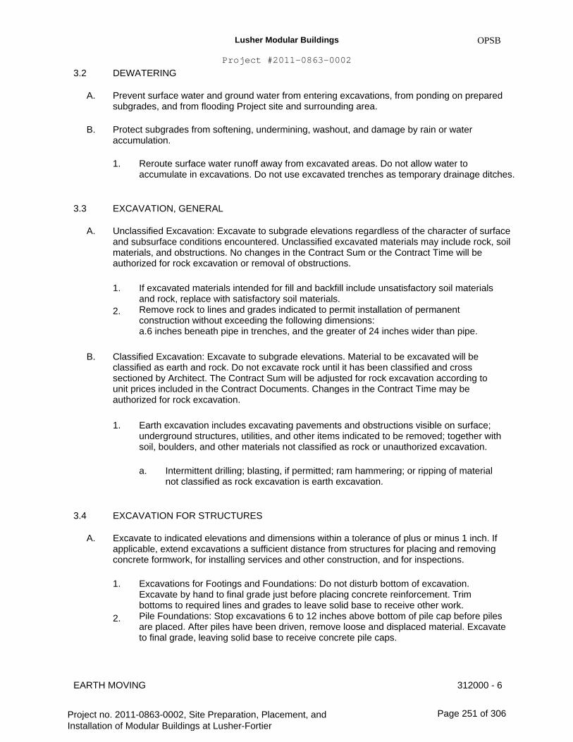
Lusher Modular Buildings
Project #2011-0863-0002
3.2
A.
B.
DEWATERING
OPSB
Prevent surface water and ground water from entering excavations, from ponding on prepared subgrades, and from flooding Project site and surrounding area.
Protect subgrades from softening, undermining, washout, and damage by rain or water accumulation.
1. Reroute surface water runoff away from excavated areas. Do not allow water to accumulate in excavations. Do not use excavated trenches as temporary drainage ditches.
3.3
A.
EXCAVATION, GENERAL
Unclassified Excavation: Excavate to subgrade elevations regardless of the character of surface and subsurface conditions encountered. Unclassified excavated materials may include rock, soil materials, and obstructions. No changes in the Contract Sum or the Contract Time will be authorized for rock excavation or removal of obstructions.
1.
2.
If excavated materials intended for fill and backfill include unsatisfactory soil materials and rock, replace with satisfactory soil materials. Remove rock to lines and grades indicated to permit installation of permanent construction without exceeding the following dimensions: a.6 inches beneath pipe in trenches, and the greater of 24 inches wider than pipe.
B. Classified Excavation: Excavate to subgrade elevations. Material to be excavated will be classified as earth and rock. Do not excavate rock until it has been classified and cross sectioned by Architect. The Contract Sum will be adjusted for rock excavation according to unit prices included in the Contract Documents. Changes in the Contract Time may be authorized for rock excavation.
1. Earth excavation includes excavating pavements and obstructions visible on surface; underground structures, utilities, and other items indicated to be removed; together with soil, boulders, and other materials not classified as rock or unauthorized excavation.
a. Intermittent drilling; blasting, if permitted; ram hammering; or ripping of material not classified as rock excavation is earth excavation.
3.4
A.
EXCAVATION FOR STRUCTURES
Excavate to indicated elevations and dimensions within a tolerance of plus or minus 1 inch. If applicable, extend excavations a sufficient distance from structures for placing and removing concrete formwork, for installing services and other construction, and for inspections.
1. Excavations for Footings and Foundations: Do not disturb bottom of excavation. Excavate by hand to final grade just before placing concrete reinforcement. Trim bottoms to required lines and grades to leave solid base to receive other work. Pile Foundations: Stop excavations 6 to 12 inches above bottom of pile cap before piles are placed. After piles have been driven, remove loose and displaced material. Excavate to final grade, leaving solid base to receive concrete pile caps.
2.
EARTH MOVING 312000 - 6
Project no. 2011-0863-0002, Site Preparation, Placement, and Installation of Modular Buildings at Lusher-Fortier
Page 251 of 306

Lusher Modular Buildings
Project #2011-0863-0002
3.
OPSB
Excavation for Underground Tanks, Basins, and Mechanical or Electrical Utility Structures: Excavate to elevations and dimensions indicated within a tolerance of plus or minus 1 inch. Do not disturb bottom of excavations intended as bearing surfaces.
B. Excavations at Edges of Tree- and Plant-Protection Zones:
1. Excavate by hand to indicated lines, cross sections, elevations, and subgrades. Use narrow-tine spading forks to comb soil and expose roots. Do not break, tear, or chop exposed roots. Do not use mechanical equipment that rips, tears, or pulls roots.
3.5
A.
EXCAVATION FOR WALKS AND PAVEMENTS
Excavate surfaces under walks and pavements to indicated lines, cross sections, elevations, and subgrades.
EXCAVATION FOR UTILITY TRENCHES
A. Excavate trenches to indicated gradients, lines, depths, and elevations.
1.
B.
Beyond building perimeter, excavate trenches to allow installation of top of pipe below frost line.
3.6
Excavate trenches to uniform widths to provide the following clearance on each side of pipe or conduit. Excavate trench walls vertically from trench bottom to 12 inches higher than top of pipe or conduit unless otherwise indicated.
1. Clearance: 12 inches each side of pipe or conduit or as indicated on the plans.
C. Trench Bottoms: Excavate and shape trench bottoms to provide uniform bearing and support of pipes and conduit. Shape subgrade to provide continuous support for bells, joints, and barrels of pipes and for joints, fittings, and bodies of conduits. Remove projecting stones and sharp objects along trench subgrade.
1.
2.
For pipes and conduit less than 6 inches in nominal diameter, hand-excavate trench bottoms and support pipe and conduit on an undisturbed subgrade. For pipes and conduit 6 inches or larger in nominal diameter, shape bottom of trench to support bottom 90 degrees of pipe or conduit circumference. Fill depressions with tamped sand backfill. For flat-bottomed, multiple-duct conduit units, hand-excavate trench bottoms and support conduit on an undisturbed subgrade. Excavate trenches 6 inches deeper than elevation required in rock or other unyielding bearing material to allow for bedding course.
3.
4.
D. Trench Bottoms: Excavate trenches 4 inches deeper than bottom of pipe and conduit elevations to allow for bedding course. Hand-excavate deeper for bells of pipe.
1. Excavate trenches 6 inches deeper than elevation required in rock or other unyielding bearing material to allow for bedding course.
E. Trenches in Tree- and Plant-Protection Zones:
312000 - 7EARTH MOVING
Project no. 2011-0863-0002, Site Preparation, Placement, and Installation of Modular Buildings at Lusher-Fortier
Page 252 of 306
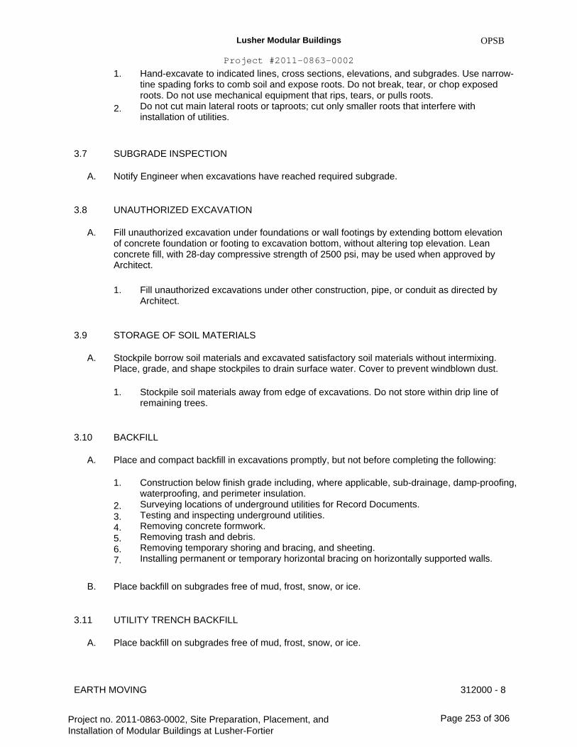
Lusher Modular Buildings
Project #2011-0863-0002
1.
OPSB
2.
Hand-excavate to indicated lines, cross sections, elevations, and subgrades. Use narrow- tine spading forks to comb soil and expose roots. Do not break, tear, or chop exposed roots. Do not use mechanical equipment that rips, tears, or pulls roots. Do not cut main lateral roots or taproots; cut only smaller roots that interfere with installation of utilities.
3.7
A.
3.8
A.
SUBGRADE INSPECTION
Notify Engineer when excavations have reached required subgrade.
UNAUTHORIZED EXCAVATION
Fill unauthorized excavation under foundations or wall footings by extending bottom elevation of concrete foundation or footing to excavation bottom, without altering top elevation. Lean concrete fill, with 28-day compressive strength of 2500 psi, may be used when approved by Architect.
1. Fill unauthorized excavations under other construction, pipe, or conduit as directed by Architect.
3.9
A.
STORAGE OF SOIL MATERIALS
Stockpile borrow soil materials and excavated satisfactory soil materials without intermixing. Place, grade, and shape stockpiles to drain surface water. Cover to prevent windblown dust.
1. Stockpile soil materials away from edge of excavations. Do not store within drip line of remaining trees.
3.10
A.
BACKFILL
Place and compact backfill in excavations promptly, but not before completing the following:
1.
2. 3. 4. 5. 6. 7.
Construction below finish grade including, where applicable, sub-drainage, damp-proofing, waterproofing, and perimeter insulation. Surveying locations of underground utilities for Record Documents. Testing and inspecting underground utilities. Removing concrete formwork. Removing trash and debris. Removing temporary shoring and bracing, and sheeting. Installing permanent or temporary horizontal bracing on horizontally supported walls.
B.
3.11
A.
Place backfill on subgrades free of mud, frost, snow, or ice.
UTILITY TRENCH BACKFILL
Place backfill on subgrades free of mud, frost, snow, or ice.
EARTH MOVING 312000 - 8
Project no. 2011-0863-0002, Site Preparation, Placement, and Installation of Modular Buildings at Lusher-Fortier
Page 253 of 306

Lusher Modular Buildings
Project #2011-0863-0002
B.
OPSB
Place and compact bedding course on trench bottoms and where indicated. Shape bedding course to provide continuous support for bells, joints, and barrels of pipes and for joints, fittings, and bodies of conduits.
Trenches under Roadways: Provide 4-inch thick, concrete-base slab support for piping or conduit less than 30 inches below surface of roadways. After installing and testing, completely encase piping or conduit in a minimum of 4 inches of concrete before backfilling or placing roadway sub-base course.
Backfill voids with satisfactory soil while removing shoring and bracing.
Place and compact initial backfill of satisfactory soil, free of particles larger than 1 inch in any dimension, to a height of 12 inches over the pipe or conduit.
1. Carefully compact initial backfill under pipe haunches and compact evenly up on both sides and along the full length of piping or conduit to avoid damage or displacement of piping or conduit. Coordinate backfilling with utilities testing.
C.
D.
E.
F.
G.
Place and compact final backfill of satisfactory soil to final subgrade elevation.
Install warning tape directly above utilities, 12 inches below finished grade, except 6 inches below subgrade under pavements and slabs.
SOIL FILL
Plow, scarify, bench, or break up sloped surfaces steeper than 1 vertical to 4 horizontal so fill material will bond with existing material.
Place and compact fill material in layers to required elevations as follows:
1. 2. 3. 4. 5.
Under grass and planted areas, use satisfactory soil material. Under walks and pavements, use satisfactory soil material. Under steps and ramps, use engineered fill. Under building slabs, use engineered fill. Under footings and foundations, use engineered fill.
3.12
A.
B.
C.
3.13
A.
Place soil fill on subgrades free of mud, frost, snow, or ice.
SOIL MOISTURE CONTROL
Uniformly moisten or aerate subgrade and each subsequent fill or backfill soil layer before compaction to within 2 percent of optimum moisture content.
1.
2.
Do not place backfill or fill soil material on surfaces that are muddy, frozen, or contain frost or ice. Remove and replace, or scarify and air dry, otherwise satisfactory soil material that exceeds optimum moisture content by 2 percent and is too wet to compact to specified dry unit weight.
EARTH MOVING 312000 - 9
Project no. 2011-0863-0002, Site Preparation, Placement, and Installation of Modular Buildings at Lusher-Fortier
Page 254 of 306

Lusher Modular Buildings
Project #2011-0863-0002
3.14
A.
OPSB
COMPACTION OF SOIL BACKFILLS AND FILLS
Place backfill and fill soil materials in layers not more than 8 inches in loose depth for material compacted by heavy compaction equipment, and not more than 4 inches in loose depth for material compacted by hand-operated tampers.
Place backfill and fill soil materials evenly on all sides of structures to required elevations, and uniformly along the full length of each structure.
Compact soil materials to not less than the following percentages of maximum dry unit weight according to ASTM D 698:
1.
2.
3.
4.
Under structures, building slabs, steps, and pavements, scarify and recompact top 12 inches of existing subgrade and each layer of backfill or fill soil material at 95 percent. Under walkways, scarify and recompact top 6 inches below subgrade and compact each layer of backfill or fill soil material at 92 percent. Under turf or unpaved areas, scarify and recompact top 6 inches below subgrade and compact each layer of backfill or fill soil material at 85 percent. For utility trenches, compact each layer of initial and final backfill soil material at 85 percent.
B.
C.
3.15
A.
GRADING
General: Uniformly grade areas to a smooth surface, free of irregular surface changes. Comply with compaction requirements and grade to cross sections, lines, and elevations indicated.
1. 2.
Provide a smooth transition between adjacent existing grades and new grades. Cut out soft spots, fill low spots, and trim high spots to comply with required surface tolerances.
B. Site Rough Grading: Slope grades to direct water away from buildings and to prevent ponding. Finish subgrades to required elevations within the following tolerances:
1. 2. 3.
Turf or Unpaved Areas: Plus or minus 1 inch. Walks: Plus or minus 1 inch. Pavements: Plus or minus 1/2 inch.
3.16
A.
FIELD QUALITY CONTROL
Special Inspections: Owner will engage a qualified special inspector to perform the following special inspections:
1.
2. 3.
Determine prior to placement of fill that site has been prepared in compliance with requirements. Determine that fill material and maximum lift thickness comply with requirements. Determine, at the required frequency, that in-place density of compacted fill complies with requirements.
EARTH MOVING 312000 - 10
Project no. 2011-0863-0002, Site Preparation, Placement, and Installation of Modular Buildings at Lusher-Fortier
Page 255 of 306
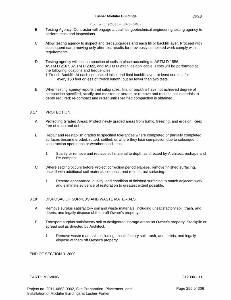
Lusher Modular Buildings
Project #2011-0863-0002
B.
C.
OPSB
Testing Agency: Contractor will engage a qualified geotechnical engineering testing agency to perform tests and inspections.
Allow testing agency to inspect and test subgrades and each fill or backfill layer. Proceed with subsequent earth moving only after test results for previously completed work comply with requirements.
Testing agency will test compaction of soils in place according to ASTM D 1556, ASTM D 2167, ASTM D 2922, and ASTM D 2937, as applicable. Tests will be performed at the following locations and frequencies: 1.Trench Backfill: At each compacted initial and final backfill layer, at least one test for every 150 feet or less of trench length, but no fewer than two tests.
When testing agency reports that subgrades, fills, or backfills have not achieved degree of compaction specified, scarify and moisten or aerate, or remove and replace soil materials to depth required; re-compact and retest until specified compaction is obtained.
PROTECTION
Protecting Graded Areas: Protect newly graded areas from traffic, freezing, and erosion. Keep free of trash and debris.
Repair and reestablish grades to specified tolerances where completed or partially completed surfaces become eroded, rutted, settled, or where they lose compaction due to subsequent construction operations or weather conditions.
1. Scarify or remove and replace soil material to depth as directed by Architect; reshape and Re-compact.
D.
E.
3.17
A.
B.
C. Where settling occurs before Project correction period elapses, remove finished surfacing, backfill with additional soil material, compact, and reconstruct surfacing.
1. Restore appearance, quality, and condition of finished surfacing to match adjacent work, and eliminate evidence of restoration to greatest extent possible.
3.18
A.
B.
DISPOSAL OF SURPLUS AND WASTE MATERIALS
Remove surplus satisfactory soil and waste materials, including unsatisfactory soil, trash, and debris, and legally dispose of them off Owner's property.
Transport surplus satisfactory soil to designated storage areas on Owner's property. Stockpile or spread soil as directed by Architect.
1. Remove waste materials, including unsatisfactory soil, trash, and debris, and legally dispose of them off Owner's property.
END OF SECTION 312000
EARTH MOVING 312000 - 11
Project no. 2011-0863-0002, Site Preparation, Placement, and Installation of Modular Buildings at Lusher-Fortier
Page 256 of 306

Lusher Modular Buildings
Project #2011-0863-0002
OPSB
SECTION 312319 - DEWATERING
PART 1 - GENERAL
1.1
A.
RELATED DOCUMENTS
Drawings and general provisions of the Contract, including General and Supplementary Conditions and Division 01 Specification Sections, apply to this Section.
SUMMARY
A.
B.
Section includes construction dewatering.
Related Sections:
1.
2.
Division 01 Section "Construction Progress Documentation & Photographic Documentation" for recording preexisting conditions and dewatering system progress. Division 31 Section "Earth Moving" for excavating, backfilling, site grading, and for site utilities.
1.2
1.3
A.
PERFORMANCE REQUIREMENTS
Dewatering Performance: Design, furnish, install, test, operate, monitor, and maintain dewatering system of sufficient scope, size, and capacity to control hydrostatic pressures and to lower, control, remove, and dispose of ground water and permit excavation and construction to proceed on dry, stable subgrades.
1. Delegated Design: Design dewatering system, including comprehensive engineering analysis by a qualified professional engineer, using performance requirements and design criteria indicated. Continuously monitor and maintain dewatering operations to ensure erosion control, stability of excavations and constructed slopes, that excavation does not flood, and that damage to subgrades and permanent structures is prevented. Prevent surface water from entering excavations by grading, dikes, or other means. Accomplish dewatering without damaging existing buildings, structures, and site improvements adjacent to excavation. Remove dewatering system when no longer required for construction.
2.
3. 4.
5.
1.4
A.
SUBMITTALS
Shop Drawings: For dewatering system. Show arrangement, locations, and details of wells and well points; locations of risers, headers, filters, pumps, power units, and discharge lines; and means of discharge, control of sediment, and disposal of water.
1. Include layouts of piezometers and flow-measuring devices for monitoring performance of dewatering system.
DEWATERING 312319 - 1
Project no. 2011-0863-0002, Site Preparation, Placement, and Installation of Modular Buildings at Lusher-Fortier
Page 257 of 306
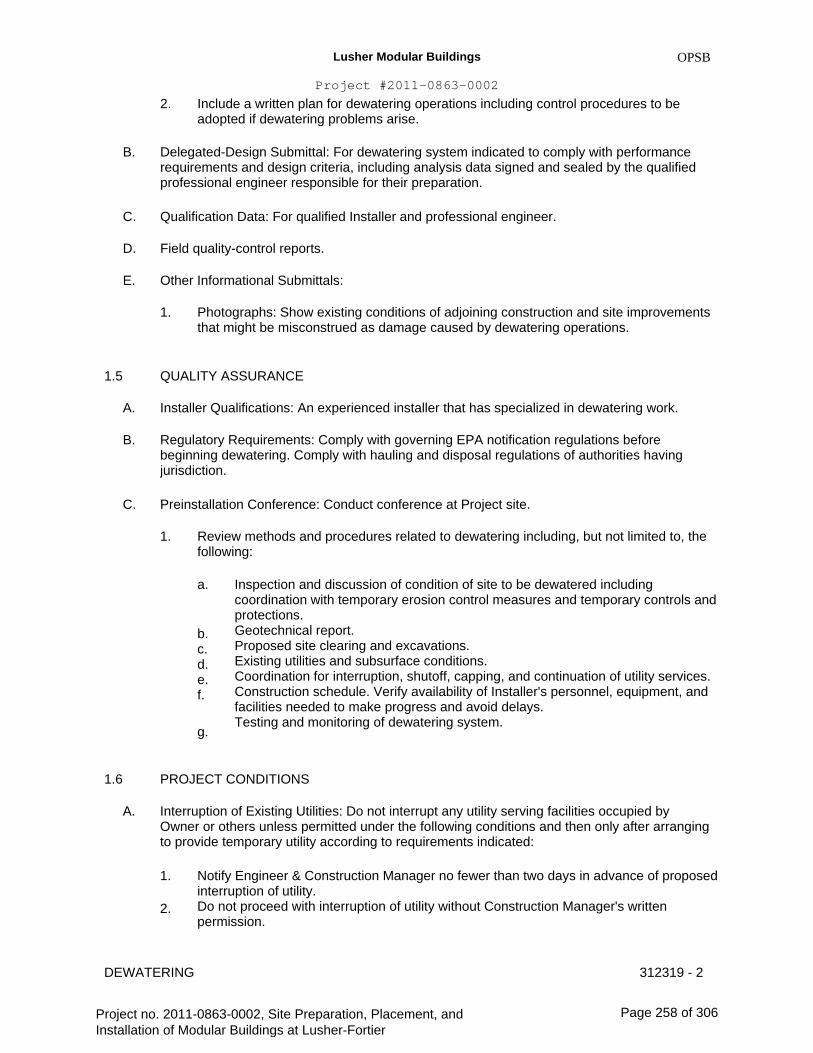
Lusher Modular Buildings
Project #2011-0863-0002
2.
B.
OPSB
Include a written plan for dewatering operations including control procedures to be adopted if dewatering problems arise.
Delegated-Design Submittal: For dewatering system indicated to comply with performance requirements and design criteria, including analysis data signed and sealed by the qualified professional engineer responsible for their preparation.
Qualification Data: For qualified Installer and professional engineer.
Field quality-control reports.
Other Informational Submittals:
1. Photographs: Show existing conditions of adjoining construction and site improvements that might be misconstrued as damage caused by dewatering operations.
C.
D.
E.
1.5
A.
B.
QUALITY ASSURANCE
Installer Qualifications: An experienced installer that has specialized in dewatering work.
Regulatory Requirements: Comply with governing EPA notification regulations before beginning dewatering. Comply with hauling and disposal regulations of authorities having jurisdiction.
Preinstallation Conference: Conduct conference at Project site.
1. Review methods and procedures related to dewatering including, but not limited to, the following:
a. Inspection and discussion of condition of site to be dewatered including coordination with temporary erosion control measures and temporary controls and protections. Geotechnical report. Proposed site clearing and excavations. Existing utilities and subsurface conditions. Coordination for interruption, shutoff, capping, and continuation of utility services. Construction schedule. Verify availability of Installer's personnel, equipment, and facilities needed to make progress and avoid delays. Testing and monitoring of dewatering system.
C.
b. c. d. e. f.
g.
1.6
A.
PROJECT CONDITIONS
Interruption of Existing Utilities: Do not interrupt any utility serving facilities occupied by Owner or others unless permitted under the following conditions and then only after arranging to provide temporary utility according to requirements indicated:
1.
2.
Notify Engineer & Construction Manager no fewer than two days in advance of proposed interruption of utility. Do not proceed with interruption of utility without Construction Manager's written permission.
312319 - 2DEWATERING
Project no. 2011-0863-0002, Site Preparation, Placement, and Installation of Modular Buildings at Lusher-Fortier
Page 258 of 306

Lusher Modular Buildings
Project #2011-0863-0002
B.
OPSB
Project-Site Information: A geotechnical report has been prepared for this Project and is available for information only. The opinions expressed in this report are those of geotechnical engineer and represent interpretations of subsoil conditions, tests, and results of analyses conducted by geotechnical engineer. Owner will not be responsible for interpretations or conclusions drawn from this data.
1. Make additional test borings and conduct other exploratory operations necessary for dewatering.
C. Survey Work: Engage a qualified land surveyor or professional engineer to survey adjacent existing buildings, structures, and site improvements, establishing exact elevations at fixed points to act as benchmarks. Clearly identify benchmarks and record existing elevations.
1. During dewatering, regularly resurvey benchmarks, maintaining an accurate log of surveyed elevations for comparison with original elevations. Promptly notify Architect if changes in elevations occur or if cracks, sags, or other damage is evident in adjacent construction.
PART 2 - PRODUCTS (Not Used)
PART 3 - EXECUTION
3.1
A.
PREPARATION
Protect structures, utilities, sidewalks, pavements, and other facilities from damage caused by settlement, lateral movement, undermining, washout, and other hazards created by dewatering operations.
1.
2.
B.
Prevent surface water and subsurface or ground water from entering excavations, from ponding on prepared subgrades, and from flooding site and surrounding area. Protect subgrades and foundation soils from softening and damage by rain or water accumulation.
Install dewatering system to ensure minimum interference with roads, streets, walks, and other adjacent occupied and used facilities.
1. Do not close or obstruct streets, walks, or other adjacent occupied or used facilities without permission from Owner and authorities having jurisdiction. Provide alternate routes around closed or obstructed traffic ways if required by authorities having jurisdiction.
C.
D.
E.
F.
Provide temporary grading to facilitate dewatering and control of surface water.
Monitor dewatering systems continuously.
Promptly repair damages to adjacent facilities caused by dewatering.
Protect and maintain temporary erosion and sedimentation controls.
DEWATERING 312319 - 3
Project no. 2011-0863-0002, Site Preparation, Placement, and Installation of Modular Buildings at Lusher-Fortier
Page 259 of 306
Lusher Modular Buildings
Project #2011-0863-0002
3.2
A.
INSTALLATION
OPSB
Install dewatering system utilizing wells, well points, or similar methods complete with pump equipment, standby power and pumps, filter material gradation, valves, appurtenances, water disposal, and surface-water controls.
1. 2.
Space well points or wells at intervals required to provide sufficient dewatering. Use filters or other means to prevent pumping of fine sands or silts from the subsurface.
B. Before excavating below ground-water level, place system into operation to lower water to specified levels. Operate system continuously until drains, sewers, and structures have been constructed and fill materials have been placed or until dewatering is no longer required.
Provide an adequate system to lower and control ground water to permit excavation, construction of structures, and placement of fill materials on dry subgrades. Install sufficient dewatering equipment to drain water-bearing strata above and below bottom of foundations, drains, sewers, and other excavations.
1. Do not permit open-sump pumping that leads to loss of fines, soil piping, subgrade softening, and slope instability.
C.
D. Reduce hydrostatic head in water-bearing strata below subgrade elevations of foundations, drains, sewers, and other excavations.
1. Maintain Piezo-metric water level a minimum of 24 inches below surface of excavation.
E. Dispose of water removed by dewatering in a manner that avoids endangering public health, property, and portions of work under construction or completed. Dispose of water and sediment in a manner that avoids inconvenience to others. Provide sumps, sedimentation tanks, and other flow-control devices as required by authorities having jurisdiction.
Provide standby equipment on site, installed and available for immediate operation, to maintain dewatering on continuous basis if any part of system becomes inadequate or fails. If dewatering requirements are not satisfied due to inadequacy or failure of dewatering system, restore damaged structures and foundation soils at no additional expense to Owner.
1. Remove dewatering system from Project site on completion of dewatering. Plug or fill well holes with sand or cut off and cap wells a minimum of 36 inches below overlying construction.
F.
G.
3.3
A.
Damages: Promptly repair damages to adjacent facilities caused by dewatering operations.
FIELD QUALITY CONTROL
Observation Wells: Provide, take measurements, and maintain at least the minimum number of observation wells or piezometers indicated; additional observation wells may be required by authorities having jurisdiction.
1. Observe and record daily elevation of ground water and piezometric water levels in observation wells.
DEWATERING 312319 - 4
Project no. 2011-0863-0002, Site Preparation, Placement, and Installation of Modular Buildings at Lusher-Fortier
Page 260 of 306
Lusher Modular Buildings
Project #2011-0863-0002
2.
OPSB
3.
B.
Repair or replace, within 24 hours, observation wells that become inactive, damaged, or destroyed. In areas where observation wells are not functioning properly, suspend construction activities until reliable observations can be made. Add or remove water from observation-well risers to demonstrate that observation wells are functioning properly. Fill observation wells, remove piezometers, and fill holes when dewatering is completed.
Provide continual observation to ensure that subsurface soils are not being removed by the dewatering operation.
END OF SECTION 312319
DEWATERING 312319 - 5
Project no. 2011-0863-0002, Site Preparation, Placement, and Installation of Modular Buildings at Lusher-Fortier
Page 261 of 306
Lusher Modular Buildings
Project #2011-0863-0002
OPSB
SECTION 321313 - CONCRETE PAVING
PART 1 - GENERAL
1.1
A.
RELATED DOCUMENTS
Drawings and general provisions of the Contract, including General and Supplementary Conditions and Division 01 Specification Sections, apply to this Section.
SUMMARY
A. Section Includes:
1. 2. 3. 4. 5.
1.3
A.
Driveways. Roadways. Parking lots. Curbs and gutters. Walks.
1.2
DEFINITIONS
Cementitious Materials: Portland cement alone or in combination with one or more of blended hydraulic cement, fly ash and other pozzolans, and ground granulated blast-furnace slag.
SUBMITTALS
A.
B.
Product Data: For each type of product indicated.
LEED Submittals: 1.Design Mixtures for Credit ID 1.1: For each concrete mixture containing fly ash as a replacement for Portland cement or other Portland cement replacements. For each design mixture submitted, include an equivalent concrete mixture that does not contain Portland cement replacements, to determine amount of Portland cement replaced.
Action Submittals:
1. Design Mixtures: For each concrete paving mixture. Include alternate design mixtures when characteristics of materials, Project conditions, weather, test results, or other circumstances warrant adjustments.
1.4
C.
D.
E.
Qualification Data: For qualified ready-mix concrete manufacturer and testing agency the contractor shall employ a qualified testing agency.
Material Certificates: For the following, from manufacturer:
1. Cementitious materials.
CONCRETE PAVING 321313 - 1
Project no. 2011-0863-0002, Site Preparation, Placement, and Installation of Modular Buildings at Lusher-Fortier
Page 262 of 306
Lusher Modular Buildings
Project #2011-0863-0002
2. 3. 4. 5. 6. 7. 8.
F.
OPSB
Steel reinforcement and reinforcement accessories. Fiber reinforcement. Admixtures. Curing compounds. Applied finish materials. Bonding agent or epoxy adhesive. Joint fillers.
Material Test Reports: For each of the following:
1. Aggregates. Include service-record data indicating absence of deleterious expansion of concrete due to alkali-aggregate reactivity.
G.
1.5
A.
Field quality-control reports.
QUALITY ASSURANCE
Ready-Mix-Concrete Manufacturer Qualifications: A firm experienced in manufacturing ready- mixed concrete products and that complies with ASTM C 94/C 94M requirements for production facilities and equipment.
1. Manufacturer certified according to NRMCA's "Certification of Ready Mixed Concrete Production Facilities" (Quality Control Manual - Section 3, "Plant Certification Checklist").
B. Testing Agency Qualifications: Qualified according to ASTM C 1077 and ASTM E 329 for testing indicated.
1. Personnel conducting field tests shall be qualified as ACI Concrete Field Testing Technician, Grade 1, according to ACI CP-1 or an equivalent certification program.
C.
D.
E.
Concrete Testing Service: Engage a qualified testing agency to perform material evaluation tests and to design concrete mixtures.
ACI Publications: Comply with ACI 301 (ACI 301M) unless otherwise indicated.
Pre-installation Conference: Conduct conference at Project site.
1. Review methods and procedures related to concrete paving, including but not limited to, the following:
a. b.
2.
Concrete mixture design. Quality control of concrete materials and concrete paving construction practices.
Require representatives of each entity directly concerned with concrete paving to attend, including the following:
a. b. c. d.
Contractor's superintendent. Independent testing agency responsible for concrete design mixtures. Ready-mix concrete manufacturer. Concrete paving subcontractor.
321313 - 2CONCRETE PAVING
Project no. 2011-0863-0002, Site Preparation, Placement, and Installation of Modular Buildings at Lusher-Fortier
Page 263 of 306

Lusher Modular Buildings
Project #2011-0863-0002
1.6
A.
PROJECT CONDITIONS
OPSB
Traffic Control: Maintain access for vehicular and pedestrian traffic as required for other construction activities.
PART 2 - PRODUCTS
2.1
A.
FORMS
Form Materials: Plywood, metal, metal-framed plywood, or other approved panel-type materials to provide full-depth, continuous, straight, and smooth exposed surfaces.
1.
B.
Use flexible or uniformly curved forms for curves with a radius of 100 feet or less.
Form-Release Agent: Commercially formulated form-release agent that will not bond with, stain, or adversely affect concrete surfaces and that will not impair subsequent treatments of concrete surfaces.
STEEL REINFORCEMENT 2.2
A. Recycled Content: Provide steel reinforcement with an average recycled content of steel so postconsumer recycled content plus one-half of pre-consumer recycled content is not less than 25 percent.
Plain-Steel Welded Wire Reinforcement: ASTM A 185/A 185M, fabricated from galvanized steel wire into flat sheets.
Deformed-Steel Welded Wire Reinforcement: ASTM A 497/A 497M, flat sheet.
Epoxy-Coated Welded Wire Reinforcement: ASTM A 884/A 884M, Class A, plain steel.
CONCRETE MATERIALS
B.
C.
D.
2.3
A. Cementitious Material: Use the following cementitious materials, of same type, brand, and source throughout Project:
1. Portland Cement: ASTM C 150, white Portland cement Type III. Supplement with the following:
a. b.
2.
Fly Ash: ASTM C 618, Class C. Ground Granulated Blast-Furnace Slag: ASTM C 989, Grade 100 or 120.
Blended Hydraulic Cement: ASTM C 595, Type IP, Portland-Pozzolan cement.
B. Normal-Weight Aggregates: ASTM C 33. Provide aggregates from a single source approved by the Louisiana Department of Transportation.
1. Maximum Coarse-Aggregate Size: 1 inch nominal.
CONCRETE PAVING 321313 - 3
Project no. 2011-0863-0002, Site Preparation, Placement, and Installation of Modular Buildings at Lusher-Fortier
Page 264 of 306
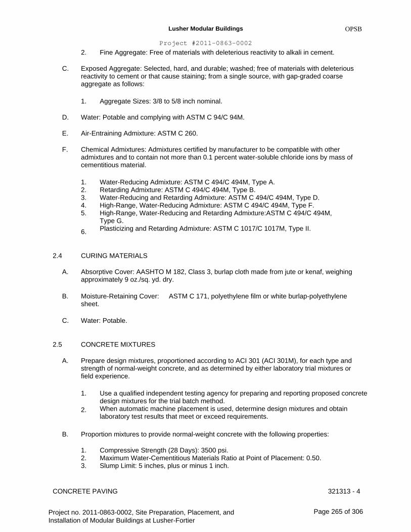
Lusher Modular Buildings
Project #2011-0863-0002
2.
C.
OPSB
Fine Aggregate: Free of materials with deleterious reactivity to alkali in cement.
Exposed Aggregate: Selected, hard, and durable; washed; free of materials with deleterious reactivity to cement or that cause staining; from a single source, with gap-graded coarse aggregate as follows:
1. Aggregate Sizes: 3/8 to 5/8 inch nominal.
D.
E.
F.
Water: Potable and complying with ASTM C 94/C 94M.
Air-Entraining Admixture: ASTM C 260.
Chemical Admixtures: Admixtures certified by manufacturer to be compatible with other admixtures and to contain not more than 0.1 percent water-soluble chloride ions by mass of cementitious material.
1. 2. 3. 4. 5.
6.
Water-Reducing Admixture: ASTM C 494/C 494M, Type A. Retarding Admixture: ASTM C 494/C 494M, Type B. Water-Reducing and Retarding Admixture: ASTM C 494/C 494M, Type D. High-Range, Water-Reducing Admixture: ASTM C 494/C 494M, Type F. High-Range, Water-Reducing and Retarding Admixture:ASTM C 494/C 494M, Type G. Plasticizing and Retarding Admixture: ASTM C 1017/C 1017M, Type II.
2.4
A.
B.
C.
2.5
A.
CURING MATERIALS
Absorptive Cover: AASHTO M 182, Class 3, burlap cloth made from jute or kenaf, weighing approximately 9 oz./sq. yd. dry.
Moisture-Retaining Cover: sheet.
Water: Potable.
CONCRETE MIXTURES
Prepare design mixtures, proportioned according to ACI 301 (ACI 301M), for each type and strength of normal-weight concrete, and as determined by either laboratory trial mixtures or field experience.
1.
2.
B.
Use a qualified independent testing agency for preparing and reporting proposed concrete design mixtures for the trial batch method. When automatic machine placement is used, determine design mixtures and obtain laboratory test results that meet or exceed requirements.
ASTM C 171, polyethylene film or white burlap-polyethylene
Proportion mixtures to provide normal-weight concrete with the following properties:
1. 2. 3.
Compressive Strength (28 Days): 3500 psi. Maximum Water-Cementitious Materials Ratio at Point of Placement: 0.50. Slump Limit: 5 inches, plus or minus 1 inch.
321313 - 4CONCRETE PAVING
Project no. 2011-0863-0002, Site Preparation, Placement, and Installation of Modular Buildings at Lusher-Fortier
Page 265 of 306

Lusher Modular Buildings
Project #2011-0863-0002
C.
OPSB
Add air-entraining admixture at manufacturer's prescribed rate to result in normal-weight concrete at point of placement having an air content as follows:
1. Air Content: 4-1/2 percent plus or minus 1.5 percent for 1-1/2-inch nominal maximum aggregate size.
D.
E.
Limit water-soluble, chloride-ion content in hardened concrete to 0.30 percent by weight of cement.
Chemical Admixtures: Use admixtures according to manufacturer's written instructions.
1.
2.
Use plasticizing and retarding admixture in concrete as required for placement and workability. Use water-reducing and retarding admixture when required by high temperatures, low humidity, or other adverse placement conditions.
F. Cementitious Materials: Limit percentage by weight of cementitious materials other than portland cement according to ACI 301 (ACI 301M) requirements as follows:
1. 2. 3.
Fly Ash or Pozzolan: 25 percent. Ground Granulated Blast-Furnace Slag: 50 percent. Combined Fly Ash or Pozzolan, and Ground Granulated Blast-Furnace Slag: 50 percent, with fly ash or pozzolan not exceeding 25 percent.
G.
H.
Synthetic Fiber: Uniformly disperse in concrete mixture at manufacturer's recommended rate, but not less than 1.5 lb/cu. yd.
Color Pigment: Add color pigment to concrete mixture according to manufacturer's written instructions and to result in hardened concrete color consistent with approved mockup.
CONCRETE MIXING 2.6
A. Ready-Mixed Concrete: Measure, batch, and mix concrete materials and concrete according to ASTM C 94/C 94M. Furnish batch certificates for each batch discharged and used in the Work.
1. When air temperature is between 85 and 90 deg F, reduce mixing and delivery time from 1-1/2 hours to 75 minutes; when air temperature is above 90 deg F, reduce mixing and delivery time to 60 minutes.
B. Project-Site Mixing: Measure, batch, and mix concrete materials and concrete according to ASTM C 94/C 94M. Mix concrete materials in appropriate drum-type batch machine mixer.
1. For concrete batches of 1 cu. yd. or smaller, continue mixing at least 1-1/2 minutes, but not more than 5 minutes after ingredients are in mixer, before any part of batch is released. For concrete batches larger than 1 cu. yd., increase mixing time by 15 seconds for each additional 1 cu. yd. Provide batch ticket for each batch discharged and used in the Work, indicating Project identification name and number, date, mixture type, mixing time, quantity, and amount of water added.
2.
3.
CONCRETE PAVING 321313 - 5
Project no. 2011-0863-0002, Site Preparation, Placement, and Installation of Modular Buildings at Lusher-Fortier
Page 266 of 306

Lusher Modular Buildings
Project #2011-0863-0002
PART 3 - EXECUTION
3.1
A.
B.
EXAMINATION
OPSB
Examine exposed subgrades and sub-base surfaces for compliance with requirements for dimensional, grading, and elevation tolerances.
Proof-roll prepared sub-base surface below concrete paving to identify soft pockets and areas of excess yielding.
1. 2.
3.
Completely proof-roll sub-base in one direction. Limit vehicle speed to 3 mph. Proof-roll with a pneumatic-tired and loaded, 10-wheel, tandem-axle dump truck weighing not less than 15 tons. Correct sub-base with soft spots and areas of pumping or rutting exceeding depth of 1/2 inch according to requirements in Division 31 Section "Earth Moving."
C.
3.2
A.
3.3
A.
Proceed with installation only after unsatisfactory conditions have been corrected.
PREPARATION
Remove loose material from compacted sub-base surface immediately before placing concrete.
EDGE FORMS AND SCREED CONSTRUCTION
Set, brace, and secure edge forms, bulkheads, and intermediate screed guides to required lines, grades, and elevations. Install forms to allow continuous progress of work and so forms can remain in place at least 24 hours after concrete placement.
Clean forms after each use and coat with form-release agent to ensure separation from concrete without damage.
STEEL REINFORCEMENT
B.
3.4
A.
B.
C.
General: Comply with CRSI's "Manual of Standard Practice" for fabricating, placing, and supporting reinforcement.
Clean reinforcement of loose rust and mill scale, earth, ice, or other bond-reducing materials.
Install welded wire reinforcement in lengths as long as practicable. Lap adjoining pieces at least one full mesh, and lace splices with wire. Offset laps of adjoining widths to prevent continuous laps in either direction.
Zinc-Coated Reinforcement: Use galvanized-steel wire ties to fasten zinc-coated reinforcement. Repair cut and damaged zinc coatings with zinc repair material.
D.
CONCRETE PAVING 321313 - 6
Project no. 2011-0863-0002, Site Preparation, Placement, and Installation of Modular Buildings at Lusher-Fortier
Page 267 of 306
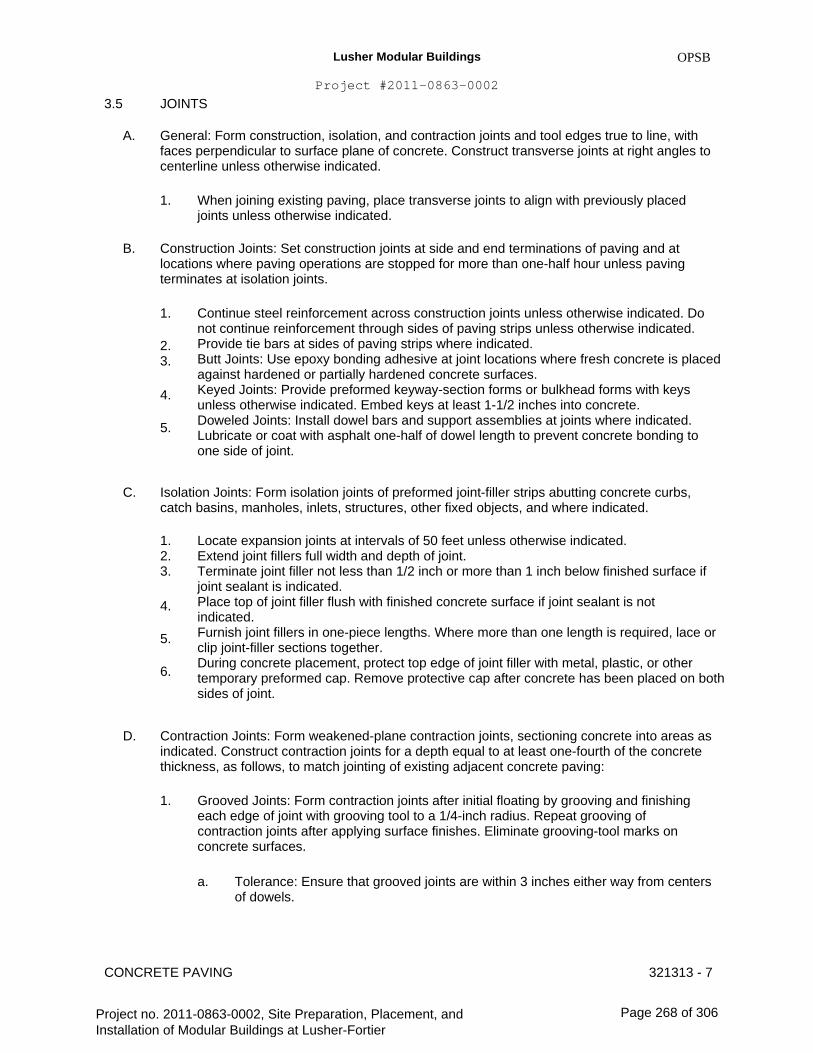
Lusher Modular Buildings
Project #2011-0863-0002
3.5
A.
JOINTS
OPSB
General: Form construction, isolation, and contraction joints and tool edges true to line, with faces perpendicular to surface plane of concrete. Construct transverse joints at right angles to centerline unless otherwise indicated.
1. When joining existing paving, place transverse joints to align with previously placed joints unless otherwise indicated.
B. Construction Joints: Set construction joints at side and end terminations of paving and at locations where paving operations are stopped for more than one-half hour unless paving terminates at isolation joints.
1.
2. 3.
4.
5.
Continue steel reinforcement across construction joints unless otherwise indicated. Do not continue reinforcement through sides of paving strips unless otherwise indicated. Provide tie bars at sides of paving strips where indicated. Butt Joints: Use epoxy bonding adhesive at joint locations where fresh concrete is placed against hardened or partially hardened concrete surfaces. Keyed Joints: Provide preformed keyway-section forms or bulkhead forms with keys unless otherwise indicated. Embed keys at least 1-1/2 inches into concrete. Doweled Joints: Install dowel bars and support assemblies at joints where indicated. Lubricate or coat with asphalt one-half of dowel length to prevent concrete bonding to one side of joint.
C. Isolation Joints: Form isolation joints of preformed joint-filler strips abutting concrete curbs, catch basins, manholes, inlets, structures, other fixed objects, and where indicated.
1. 2. 3.
4.
5.
6.
Locate expansion joints at intervals of 50 feet unless otherwise indicated. Extend joint fillers full width and depth of joint. Terminate joint filler not less than 1/2 inch or more than 1 inch below finished surface if joint sealant is indicated. Place top of joint filler flush with finished concrete surface if joint sealant is not indicated. Furnish joint fillers in one-piece lengths. Where more than one length is required, lace or clip joint-filler sections together. During concrete placement, protect top edge of joint filler with metal, plastic, or other temporary preformed cap. Remove protective cap after concrete has been placed on both sides of joint.
D. Contraction Joints: Form weakened-plane contraction joints, sectioning concrete into areas as indicated. Construct contraction joints for a depth equal to at least one-fourth of the concrete thickness, as follows, to match jointing of existing adjacent concrete paving:
1. Grooved Joints: Form contraction joints after initial floating by grooving and finishing each edge of joint with grooving tool to a 1/4-inch radius. Repeat grooving of contraction joints after applying surface finishes. Eliminate grooving-tool marks on concrete surfaces.
a. Tolerance: Ensure that grooved joints are within 3 inches either way from centers of dowels.
CONCRETE PAVING 321313 - 7
Project no. 2011-0863-0002, Site Preparation, Placement, and Installation of Modular Buildings at Lusher-Fortier
Page 268 of 306

Lusher Modular Buildings
Project #2011-0863-0002
2.
OPSB
Sawed Joints: Form contraction joints with power saws equipped with shatterproof abrasive or diamond-rimmed blades. Cut 1/8-inch- wide joints into concrete when cutting action will not tear, abrade, or otherwise damage surface and before developing random contraction cracks.
a. Tolerance: Ensure that sawed joints are within 3 inches either way from centers of dowels.
3. Doweled Contraction Joints: Install dowel bars and support assemblies at joints where indicated. Lubricate or coat with asphalt one-half of dowel length to prevent concrete bonding to one side of joint.
E. Edging: After initial floating, tool edges of paving, gutters, curbs, and joints in concrete with an edging tool to a 1/4-inch radius. Repeat tooling of edges after applying surface finishes. Eliminate edging-tool marks on concrete surfaces.
CONCRETE PLACEMENT 3.6
A.
B.
C.
Before placing concrete, inspect and complete formwork installation, steel reinforcement, and items to be embedded or cast-in.
Remove snow, ice, or frost from sub-base surface and steel reinforcement before placing concrete. Do not place concrete on frozen surfaces.
Moisten sub-base to provide a uniform dampened condition at time concrete is placed. Do not place concrete around manholes or other structures until they are at required finish elevation and alignment.
Comply with ACI 301 (ACI 301M) requirements for measuring, mixing, transporting, and placing concrete.
Do not add water to concrete during delivery or at Project site. Do not add water to fresh concrete after testing.
Deposit and spread concrete in a continuous operation between transverse joints. Do not push or drag concrete into place or use vibrators to move concrete into place.
Consolidate concrete according to ACI 301 (ACI 301M) by mechanical vibrating equipment supplemented by hand spading, rodding, or tamping.
1. Consolidate concrete along face of forms and adjacent to transverse joints with an internal vibrator. Keep vibrator away from joint assemblies, reinforcement, or side forms. Use only square-faced shovels for hand spreading and consolidation. Consolidate with care to prevent dislocating reinforcement and joint devices.
D.
E.
F.
G.
H.
I.
Screed paving surface with a straightedge and strike off.
Commence initial floating using bull floats or darbies to impart an open-textured and uniform surface plane before excess moisture or bleed water appears on the surface. Do not further disturb concrete surfaces before beginning finishing operations or spreading surface treatments.
CONCRETE PAVING 321313 - 8
Project no. 2011-0863-0002, Site Preparation, Placement, and Installation of Modular Buildings at Lusher-Fortier
Page 269 of 306

Lusher Modular Buildings
Project #2011-0863-0002
J.
OPSB
Cold-Weather Placement: Protect concrete work from physical damage or reduced strength that could be caused by frost, freezing, or low temperatures. Comply with ACI 306.1 and the following:
1. When air temperature has fallen to or is expected to fall below 40 deg F, uniformly heat water and aggregates before mixing to obtain a concrete mixture temperature of not less than 50 deg F and not more than 80 deg F at point of placement. Do not use frozen materials or materials containing ice or snow. Do not use calcium chloride, salt, or other materials containing antifreeze agents or chemical accelerators unless otherwise specified and approved in design mixtures.
2. 3.
K. Hot-Weather Placement: Comply with ACI 301 (ACI 301M) and as follows when hot-weather conditions exist:
1. Cool ingredients before mixing to maintain concrete temperature below 90 deg F at time of placement. Chilled mixing water or chopped ice may be used to control temperature, provided water equivalent of ice is calculated in total amount of mixing water. Using liquid nitrogen to cool concrete is Contractor's option. Cover steel reinforcement with water-soaked burlap so steel temperature will not exceed ambient air temperature immediately before embedding in concrete. Fog-spray forms, steel reinforcement, and subgrade just before placing concrete. Keep subgrade moisture uniform without standing water, soft spots, or dry areas.
2.
3.
3.7
A.
B.
FLOAT FINISHING
General: Do not add water to concrete surfaces during finishing operations.
Float Finish: Begin the second floating operation when bleed-water sheen has disappeared and concrete surface has stiffened sufficiently to permit operations. Float surface with power-driven floats or by hand floating if area is small or inaccessible to power units. Finish surfaces to true planes. Cut down high spots and fill low spots. Refloat surface immediately to uniform granular texture.
1.
2.
3.
Burlap Finish: Drag a seamless strip of damp burlap across float-finished concrete, perpendicular to line of traffic, to provide a uniform, gritty texture. Medium-to-Fine-Textured Broom Finish: Draw a soft-bristle broom across float-finished concrete surface perpendicular to line of traffic to provide a uniform, fine-line texture. Medium-to-Coarse-Textured Broom Finish: Provide a coarse finish by striating float- finished concrete surface 1/16 to 1/8 inch deep with a stiff-bristled broom, perpendicular to line of traffic.
3.8
A.
B.
CONCRETE PROTECTION AND CURING
General: Protect freshly placed concrete from premature drying and excessive cold or hot temperatures.
Comply with ACI 306.1 for cold-weather protection.
CONCRETE PAVING 321313 - 9
Project no. 2011-0863-0002, Site Preparation, Placement, and Installation of Modular Buildings at Lusher-Fortier
Page 270 of 306

Lusher Modular Buildings
Project #2011-0863-0002
C.
OPSB
Evaporation Retarder: Apply evaporation retarder to concrete surfaces if hot, dry, or windy conditions cause moisture loss approaching 0.2 lb/sq. ft. x h before and during finishing operations. Apply according to manufacturer's written instructions after placing, screeding, and bull floating or darbying concrete but before float finishing.
Begin curing after finishing concrete but not before free water has disappeared from concrete surface.
Curing Methods: Cure concrete by moisture-retaining-cover curing as follows:
1. Moisture Curing: Keep surfaces continuously moist for not less than seven days with the following materials:
a. b. c.
2.
Water. Continuous water-fog spray. Absorptive cover, water saturated and kept continuously wet. Cover concrete surfaces and edges with 12-inch lap over adjacent absorptive covers.
D.
E.
3.
Moisture-Retaining-Cover Curing: Cover concrete surfaces with moisture-retaining cover, placed in widest practicable width, with sides and ends lapped at least 12 inches and sealed by waterproof tape or adhesive. Immediately repair any holes or tears occurring during installation or curing period using cover material and waterproof tape. Curing Compound: Apply uniformly in continuous operation by power spray or roller according to manufacturer's written instructions. Recoat areas that have been subjected to heavy rainfall within three hours after initial application. Maintain continuity of coating, and repair damage during curing period.
3.9
A.
B.
FIELD QUALITY CONTROL
Testing Agency: Engage a qualified testing agency to perform tests and inspections.
Testing Services: Testing of composite samples of fresh concrete obtained according to ASTM C 172 shall be performed according to the following requirements:
1. Testing Frequency: Obtain at least one composite sample for each 1000 sq. ft. or fraction thereof of each concrete mixture placed each day.
a. When frequency of testing will provide fewer than five compressive-strength tests for each concrete mixture, testing shall be conducted from at least five randomly selected batches or from each batch if fewer than five are used.
2.
3.
4.
Slump: ASTM C 143/C 143M; one test at point of placement for each composite sample, but not less than one test for each day's pour of each concrete mixture. Perform additional tests when concrete consistency appears to change. Air Content: ASTM C 231, pressure method; one test for each composite sample, but not less than one test for each day's pour of each concrete mixture. Concrete Temperature: ASTM C 1064/C 1064M; one test hourly when air temperature is 40 deg F and below and when it is 80 deg F and above, and one test for each composite sample.
CONCRETE PAVING 321313 - 10
Project no. 2011-0863-0002, Site Preparation, Placement, and Installation of Modular Buildings at Lusher-Fortier
Page 271 of 306

Lusher Modular Buildings
Project #2011-0863-0002
5.
6.
OPSB
Compression Test Specimens: ASTM C 31/C 31M; cast and laboratory cure one set of three standard cylinder specimens for each composite sample. Compressive-Strength Tests: ASTM C 39/C 39M; test one specimen at seven days and two specimens at 28 days.
a. A compressive-strength test shall be the average compressive strength from two specimens obtained from same composite sample and tested at 28 days.
C. Strength of each concrete mixture will be satisfactory if average of any three consecutive compressive-strength tests equals or exceeds specified compressive strength and no compressive-strength test value falls below specified compressive strength by more than 500 psi.
Test results shall be reported in writing to Architect, concrete manufacturer, and Contractor within 48 hours of testing. Reports of compressive-strength tests shall contain Project identification name and number, date of concrete placement, name of concrete testing and inspecting agency, location of concrete batch in Work, design compressive strength at 28 days, concrete mixture proportions and materials, compressive breaking strength, and type of break for both 7- and 28-day tests.
Nondestructive Testing: Impact hammer, sonoscope, or other nondestructive device may be permitted by Architect but will not be used as sole basis for approval or rejection of concrete.
Additional Tests: Testing and inspecting agency shall make additional tests of concrete when test results indicate that slump, air entrainment, compressive strengths, or other requirements have not been met, as directed by Architect.
Concrete paving will be considered defective if it does not pass tests and inspections.
Additional testing and inspecting, at Contractor's expense, will be performed to determine compliance of replaced or additional work with specified requirements.
Prepare test and inspection reports.
REPAIRS AND PROTECTION
Remove and replace concrete paving that is broken, damaged, or defective or that does not comply with requirements in this Section. Remove work in complete sections from joint to joint unless otherwise approved by Architect.
Drill test cores, where directed by Architect, when necessary to determine magnitude of cracks or defective areas. Fill drilled core holes in satisfactory paving areas with portland cement concrete bonded to paving with epoxy adhesive.
Protect concrete paving from damage. Exclude traffic from paving for at least 14 days after placement. When construction traffic is permitted, maintain paving as clean as possible by removing surface stains and spillage of materials as they occur.
Maintain concrete paving free of stains, discoloration, dirt, and other foreign material. Sweep paving not more than two days before date scheduled for Substantial Completion inspections.
D.
E.
F.
G.
H.
I.
3.10
A.
B.
C.
D.
CONCRETE PAVING 321313 - 11
Project no. 2011-0863-0002, Site Preparation, Placement, and Installation of Modular Buildings at Lusher-Fortier
Page 272 of 306

Lusher Modular Buildings
Project #2011-0863-0002
END OF SECTION 321313
OPSB
CONCRETE PAVING 321313 - 12
Project no. 2011-0863-0002, Site Preparation, Placement, and Installation of Modular Buildings at Lusher-Fortier
Page 273 of 306

Lusher Modular Buildings
Project #2011-0863-0002
OPSB
SECTION 323113 - CHAIN LINK FENCES AND GATES
PART 1 - GENERAL
1.1
A.
RELATED DOCUMENTS
Drawings and general provisions of the Contract, including General and Supplementary Conditions and Division 01 Specification Sections, apply to this Section.
SUMMARY
A. Section Includes:
1. 2.
1.3
A.
Chain-link fences. Gates: swing.
1.2
PERFORMANCE REQUIREMENTS
Delegated Design: Design chain-link fences and gates, including comprehensive engineering analysis by a qualified professional engineer, using performance requirements and design criteria indicated.
Structural Performance: Chain-link fence and gate framework shall withstand the effects of gravity loads and the following loads and stresses within limits and under conditions indicated according to ASCE/SEI 7:
1.
2.
Minimum Post Size: Determine according to ASTM F 1043 for framework up to 12 feet high, and post spacing not to exceed 10 feet. Minimum Post Size and Maximum Spacing:Determine according to CLFMI WLG 2445, based on mesh size and pattern specified and on the following: a.Fence Height: 10 feet. b.Material Group: IA, ASTM F 1043, Schedule 40 steel pipe.
B.
C. Lightning Protection System: Maximum grounding-resistance value of 25 ohms under normal dry conditions.
SUBMITTALS 1.4
A. Product Data: For each type of product indicated. Include construction details, material descriptions, dimensions of individual components and profiles, and finishes for chain-link fences and gates.
1. 2. 3.
Fence and gate posts, rails, and fittings. Chain-link fabric, reinforcements, and attachments. Gates and hardware.
CHAIN LINK FENCES AND GATES 323113 - 1
Project no. 2011-0863-0002, Site Preparation, Placement, and Installation of Modular Buildings at Lusher-Fortier
Page 274 of 306

Lusher Modular Buildings
Project #2011-0863-0002
B.
C.
D.
OPSB
Shop Drawings: Include plans, elevations, sections, details, and attachments to other work. Show accessories, hardware, gate operation, and operational clearances.
Samples for Initial Selection: For components with factory-applied color finishes.
Samples for Verification: Prepared on Samples of size indicated below:
1. Polymer-Coated Components: In 6-inch lengths for components and on full-sized units for accessories.
E. Delegated-Design Submittal: For chain-link fences and gate framework indicated to comply with performance requirements and design criteria, including analysis data signed and sealed by the qualified professional engineer responsible for their preparation.
Qualification Data: For qualified testing agency.
Product Certificates: For each type of chain-link fence, and gate, from manufacturer.
Product Test Reports: For framing strength according to ASTM F 1043.
Field quality-control reports.
Operation and Maintenance Data: For the following to include in emergency, operation, and maintenance manuals:
1. 2. 3.
Polymer finishes. Gate hardware. Gate operator.
F.
G.
H.
I.
J.
K.
1.5
A.
Warranty: Sample of special warranty.
QUALITY ASSURANCE
Testing Agency Qualifications: For testing fence grounding. Member company of NETA or an NRTL.
1. Testing Agency's Field Supervisor: Currently certified by NETA to supervise on-site testing.
B.
C.
D.
Electrical Components, Devices, and Accessories: Listed and labeled as defined in NFPA 70, by a qualified testing agency, and marked for intended location and application.
Emergency Access Requirements: Comply with requirements of authorities having jurisdiction for gates with automatic gate operators serving as a required means of access.
Mockups: Build mockups to set quality standards for fabrication and installation.
1. Include 10-foot length of fence and gate.
E. Pre-installation Conference: Conduct conference at Project site. 1.Review coordination of interlocked equipment specified in this Section and elsewhere.
CHAIN LINK FENCES AND GATES 323113 - 2
Project no. 2011-0863-0002, Site Preparation, Placement, and Installation of Modular Buildings at Lusher-Fortier
Page 275 of 306

Lusher Modular Buildings
Project #2011-0863-0002
2.
1.6
A.
OPSB
Review required testing, inspecting, and certifying procedures.
PROJECT CONDITIONS
Field Measurements: Verify layout information for chain-link fences and gates shown on Drawings in relation to property survey and existing structures. Verify dimensions by field measurements.
WARRANTY
A. Special Warranty: Manufacturer's standard form in which Installer agrees to repair or replace components of chain-link fences and gates that fail in materials or workmanship within specified warranty period.
1. Failures include, but are not limited to, the following: a.Deterioration of metals, metal finishes, and other materials beyond normal weathering.
Warranty Period: Two years from date of Substantial Completion.
1.7
2.
PART 2 - PRODUCTS
2.1
A.
CHAIN-LINK FENCE FABRIC
General: Provide fabric in one-piece heights measured between top and bottom of outer edge of selvage knuckle or twist. Comply with CLFMI Product Manual and with requirements indicated below:
1. 2.
2.2
A.
Fabric Height: Match existing. Steel Wire Fabric: Match Existing
FENCE FRAMING
Posts and Rails: Comply with ASTM F 1043 for framing, including rails, braces, and line; terminal; and corner posts. Provide members with minimum dimensions and wall thickness according to ASTM F 1043 based on the following:
TENSION WIRE
A. Metallic-Coated Steel Wire: 0.177-inch- diameter, marcelled tension wire complying with ASTM A 817 and ASTM A 824, with the following metallic coating: 1.Type II, zinc coated (galvanized) by hot-dip process, with the following minimum coating weight: a.Matching chain-link fabric coating weight.
2.3
CHAIN LINK FENCES AND GATES 323113 - 3
Project no. 2011-0863-0002, Site Preparation, Placement, and Installation of Modular Buildings at Lusher-Fortier
Page 276 of 306

Lusher Modular Buildings
Project #2011-0863-0002
2.4
A.
SWING GATES
OPSB
General: Comply with ASTM F 900 for gate posts and single swing gate types.
1. 2.
Gate Leaf Width: As indicated. Gate Fabric Height: Match existing.
B. Pipe and Tubing:
1.
2. 3.
Zinc-Coated Steel: Comply with ASTM F 1043 and ASTM F 1083; protective coating and finish to match fence framing. Gate Posts: Round tubular steel. Gate Frames and Bracing: Round tubular steel.
C.
D.
Frame Corner Construction: Welded or assembled with corner fittings.
Hardware:
1. 2.
3. 4.
Hinges: 180-degree inward swing. Latches permitting operation from both sides of gate with provision for padlocking accessible from both sides of gate. Lock: Manufacturer's standard internal device. Closer: Manufacturer's standard.
2.5
A.
B.
FITTINGS
General: Comply with ASTM F 626.
Post Caps: Provide for each post.
1.
C.
D.
Provide line post caps with loop to receive tension wire or top rail.
Rail and Brace Ends: For each gate, corner, pull, and end post.
Rail Fittings: Provide the following:
1. 2.
Top Rail Sleeves: Pressed-steel or round-steel tubing not less than 6 inches long. Rail Clamps: Line and corner boulevard clamps for connecting intermediate and bottom rails in the fence line-to-line posts.
E.
F.
Tension and Brace Bands: Pressed steel.
Tension Bars: Steel, length not less than 2 inches shorter than full height of chain-link fabric. Provide one bar for each gate and end post, and two for each corner and pull post, unless fabric is integrally woven into post.
Truss Rod Assemblies: Steel, hot-dip galvanized after threading rod and turnbuckle or other means of adjustment.
G.
CHAIN LINK FENCES AND GATES 323113 - 4
Project no. 2011-0863-0002, Site Preparation, Placement, and Installation of Modular Buildings at Lusher-Fortier
Page 277 of 306

Lusher Modular Buildings
Project #2011-0863-0002
H.
Barbed Wire Arms: Pressed steel or cast iron, with clips, slots, or other means for attaching strands of barbed wire, and means for attaching to posts; for each post unless otherwise indicated, and as follows:
1. 2. 3.
Provide line posts with arms that accommodate top rail or tension wire. Provide corner arms at fence corner posts, unless extended posts are indicated. Type I, single slanted arm.
I. Tie Wires, Clips, and Fasteners: According to ASTM F 626.
1. Standard Round Wire Ties: For attaching chain-link fabric to posts, rails, and frames, complying with the following: a.Aluminum:ASTM B 211 (ASTM B 211M); Alloy 1350-H19; 0.192-inch diameter, mill-finished wire.
J. Finish:
1. Metallic Coating for Pressed Steel or Cast Iron: Not less than 1.2 oz. /sq. ft. zinc.
a.
2.
Polymer coating over metallic coating.
Aluminum: Mill finish.
2.6
A.
BARBED WIRE
Steel Barbed Wire: Comply with ASTM A 121, for two-strand barbed wire, 0.099-inch diameter line wire with 0.080-inch-diameter, four-point round barbs spaced not more than 5 inches o.c.
1. 2.
Aluminum Coating: Type A. Zinc Coating: Type Z, Class 3.
2.7
A.
BARBED TAPE
Wire-Reinforced Tape: ASTM F 1910; with four-point, needle-sharp barbs permanently cold clenched around a core wire.
1.
B.
C.
Core Wire: High-tensile-strength, zinc-coated steel or stainless steel.
Clips: Stainless steel, 0.065 inch thick by 0.375 inch wide, capable of withstanding a minimum 150-lbf pull load to limit extension of coil, resulting in a concertina pattern when deployed.
Tie Wires: Stainless steel, 0.065 inch in diameter.
GROUT AND ANCHORING CEMENT2.8
A. Non-shrink, Nonmetallic Grout: Premixed, factory-packaged, non-staining, noncorrosive, nongaseous grout complying with ASTM C 1107. Provide grout, recommended in writing by manufacturer, for exterior applications.
CHAIN LINK FENCES AND GATES 323113 - 5
Project no. 2011-0863-0002, Site Preparation, Placement, and Installation of Modular Buildings at Lusher-Fortier
Page 278 of 306
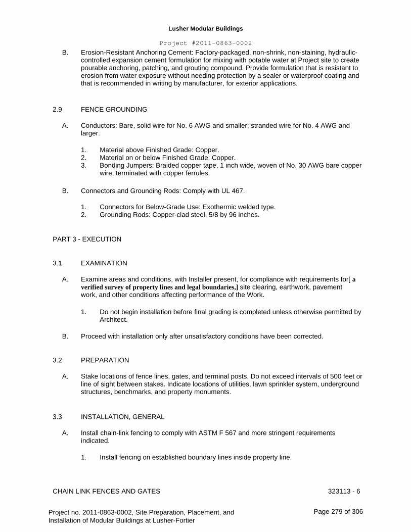
Lusher Modular Buildings
Project #2011-0863-0002
B.
Erosion-Resistant Anchoring Cement: Factory-packaged, non-shrink, non-staining, hydraulic- controlled expansion cement formulation for mixing with potable water at Project site to create pourable anchoring, patching, and grouting compound. Provide formulation that is resistant to erosion from water exposure without needing protection by a sealer or waterproof coating and that is recommended in writing by manufacturer, for exterior applications.
FENCE GROUNDING 2.9
A. Conductors: Bare, solid wire for No. 6 AWG and smaller; stranded wire for No. 4 AWG and larger.
1. 2. 3.
Material above Finished Grade: Copper. Material on or below Finished Grade: Copper. Bonding Jumpers: Braided copper tape, 1 inch wide, woven of No. 30 AWG bare copper wire, terminated with copper ferrules.
B. Connectors and Grounding Rods: Comply with UL 467.
1. 2.
Connectors for Below-Grade Use: Exothermic welded type. Grounding Rods: Copper-clad steel, 5/8 by 96 inches.
PART 3 - EXECUTION
3.1
A.
EXAMINATION
Examine areas and conditions, with Installer present, for compliance with requirements for[ a verified survey of property lines and legal boundaries,] site clearing, earthwork, pavement work, and other conditions affecting performance of the Work.
1.
B.
3.2
A.
Do not begin installation before final grading is completed unless otherwise permitted by Architect.
Proceed with installation only after unsatisfactory conditions have been corrected.
PREPARATION
Stake locations of fence lines, gates, and terminal posts. Do not exceed intervals of 500 feet or line of sight between stakes. Indicate locations of utilities, lawn sprinkler system, underground structures, benchmarks, and property monuments.
INSTALLATION, GENERAL 3.3
A. Install chain-link fencing to comply with ASTM F 567 and more stringent requirements indicated.
1. Install fencing on established boundary lines inside property line.
CHAIN LINK FENCES AND GATES 323113 - 6
Project no. 2011-0863-0002, Site Preparation, Placement, and Installation of Modular Buildings at Lusher-Fortier
Page 279 of 306

Lusher Modular Buildings
Project #2011-0863-0002
3.4
A.
B.
OPSB
CHAIN-LINK FENCE INSTALLATION
Post Excavation: Drill or hand-excavate holes for posts to diameters and spacings indicated, in firm, undisturbed soil.
Post Setting: Set posts in concrete at indicated spacing into firm, undisturbed soil.
1.
2.
Verify that posts are set plumb, aligned, and at correct height and spacing, and hold in position during setting with concrete or mechanical devices. Concrete Fill: Place concrete around posts to dimensions indicated and vibrate or tamp for consolidation. Protect aboveground portion of posts from concrete splatter.
a. b.
C.
D.
E.
Exposed Concrete: Extend 2 inches above grade; shape and smooth to shed water. Concealed Concrete: Top 2 inches below grade to allow covering with surface material.
Terminal Posts: Locate terminal end, corner, and gate posts per ASTM F 567 and terminal pull posts at changes in horizontal or vertical alignment of 30 degrees or more.
Line Posts: Space line posts uniformly at 10 feet o.c.
Post Bracing and Intermediate Rails: Install according to ASTM F 567, maintaining plumb position and alignment of fencing. Diagonally brace terminal posts to adjacent line posts with truss rods and turnbuckles. Install braces at end and gate posts and at both sides of corner and pull posts.
1. Locate horizontal braces at mid-height of fabric 72 inches or higher, on fences with top rail and at two-third fabric height on fences without top rail. Install so posts are plumb when diagonal rod is under proper tension.
F. Tension Wire: Install according to ASTM F 567, maintaining plumb position and alignment of fencing. Pull wire taut, without sags. Fasten fabric to tension wire with 0.120-inch-diameter hog rings of same material and finish as fabric wire, spaced a maximum of 24 inches o.c. Install tension wire in locations indicated before stretching fabric. Provide horizontal tension wire at the following locations:
1. Extended along top and bottom of fence fabric. Install top tension wire through post cap loops. Install bottom tension wire within 6 inches of bottom of fabric and tie to each post with not less than same diameter and type of wire. Extended along top of barbed wire arms and top of fence fabric for supporting barbed tape.
2.
G. Top Rail: Install according to ASTM F 567, maintaining plumb position and alignment of fencing. Run rail continuously through line post caps, bending to radius for curved runs and terminating into rail end attached to posts or post caps fabricated to receive rail at terminal posts. Provide expansion couplings as recommended in writing by fencing manufacturer.
Intermediate and Bottom Rails: Install and secure to posts with fittings.
Chain-Link Fabric: Apply fabric to outside of enclosing framework. Leave 1 inch between finish grade or surface and bottom selvage unless otherwise indicated. Pull fabric taut and tie to
H.
I.
CHAIN LINK FENCES AND GATES 323113 - 7
Project no. 2011-0863-0002, Site Preparation, Placement, and Installation of Modular Buildings at Lusher-Fortier
Page 280 of 306

Lusher Modular Buildings
Project #2011-0863-0002
posts, rails, and tension wires. Anchor to framework so fabric remains under tension after pulling force is released.
J.
K.
Tension or Stretcher Bars: Thread through fabric and secure to end, corner, pull, and gate posts with tension bands spaced not more than 15 inches o.c.
Tie Wires: Use wire of proper length to firmly secure fabric to line posts and rails. Attach wire at one end to chain-link fabric, wrap wire around post a minimum of 180 degrees, and attach other end to chain-link fabric per ASTM F 626. Bend ends of wire to minimize hazard to individuals and clothing.
1.
L.
M.
N.
Maximum Spacing: Tie fabric to line posts at 12 inches o.c. and to braces at 24 inches o.c.
Fasteners: Install nuts for tension bands and carriage bolts on the side of the fence opposite the fabric side.
Barbed Wire: Install barbed wire uniformly spaced, angled toward security side of fence. Pull wire taut, install securely to extension arms, and secure to end post or terminal arms.
Barbed Tape: Comply with ASTM F 1911. Install barbed tape uniformly in configurations indicated and fasten securely to prevent movement or displacement.
GATE INSTALLATION 3.5
A. Install gates according to manufacturer's written instructions, level, plumb, and secure for full opening without interference. Attach fabric as for fencing. Attach hardware using tamper- resistant or concealed means. Install ground-set items in concrete for anchorage. Adjust hardware for smooth operation and lubricate where necessary.
GATE OPERATOR INSTALLATION 3.6
A.
B.
General: Install gate operators according to manufacturer's written instructions, aligned and true to fence line and grade.
Excavation for Support Posts: Hand-excavate holes for bases/pads, in firm, undisturbed soil to dimensions and depths and at locations as required by gate-operator component manufacturer's written instructions and as indicated.
GROUNDING AND BONDING 3.7
A. Fence Grounding: Install at maximum intervals of 1500 feet (450 m) except as follows:
1. Fences within 100 Feet of Buildings, Structures, Walkways, and Roadways: Ground at maximum intervals of 750 feet.
a. Gates and Other Fence Openings: Ground fence on each side of opening.
1) Bond metal gates to gate posts.
CHAIN LINK FENCES AND GATES 323113 - 8
Project no. 2011-0863-0002, Site Preparation, Placement, and Installation of Modular Buildings at Lusher-Fortier
Page 281 of 306
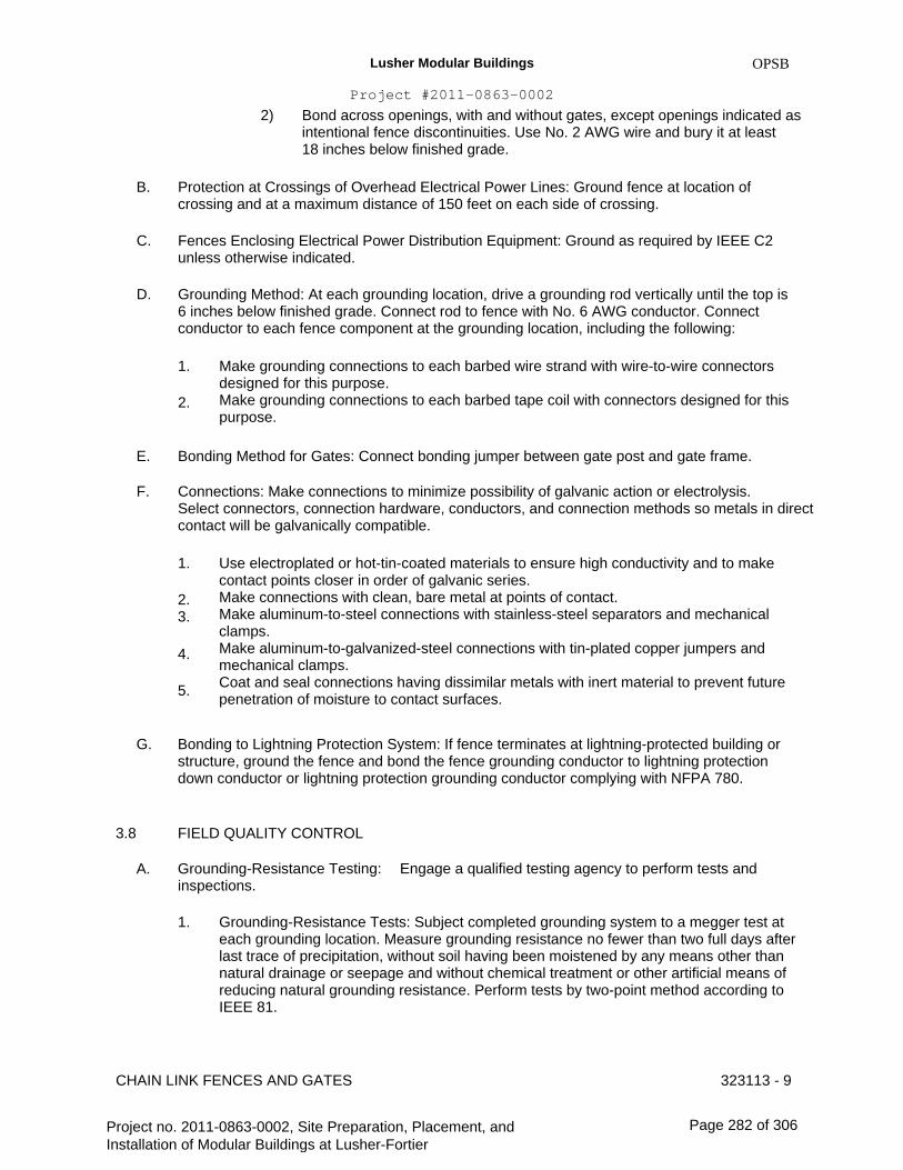
Lusher Modular Buildings
Project #2011-0863-0002
2)
OPSB
Bond across openings, with and without gates, except openings indicated as intentional fence discontinuities. Use No. 2 AWG wire and bury it at least 18 inches below finished grade.
B.
C.
D.
Protection at Crossings of Overhead Electrical Power Lines: Ground fence at location of crossing and at a maximum distance of 150 feet on each side of crossing.
Fences Enclosing Electrical Power Distribution Equipment: Ground as required by IEEE C2 unless otherwise indicated.
Grounding Method: At each grounding location, drive a grounding rod vertically until the top is 6 inches below finished grade. Connect rod to fence with No. 6 AWG conductor. Connect conductor to each fence component at the grounding location, including the following:
1.
2.
Make grounding connections to each barbed wire strand with wire-to-wire connectors designed for this purpose. Make grounding connections to each barbed tape coil with connectors designed for this purpose.
E.
F.
Bonding Method for Gates: Connect bonding jumper between gate post and gate frame.
Connections: Make connections to minimize possibility of galvanic action or electrolysis. Select connectors, connection hardware, conductors, and connection methods so metals in direct contact will be galvanically compatible.
1.
2. 3.
4.
5.
Use electroplated or hot-tin-coated materials to ensure high conductivity and to make contact points closer in order of galvanic series. Make connections with clean, bare metal at points of contact. Make aluminum-to-steel connections with stainless-steel separators and mechanical clamps. Make aluminum-to-galvanized-steel connections with tin-plated copper jumpers and mechanical clamps. Coat and seal connections having dissimilar metals with inert material to prevent future penetration of moisture to contact surfaces.
G. Bonding to Lightning Protection System: If fence terminates at lightning-protected building or structure, ground the fence and bond the fence grounding conductor to lightning protection down conductor or lightning protection grounding conductor complying with NFPA 780.
FIELD QUALITY CONTROL3.8
A. Grounding-Resistance Testing: inspections.
1.
Engage a qualified testing agency to perform tests and
Grounding-Resistance Tests: Subject completed grounding system to a megger test at each grounding location. Measure grounding resistance no fewer than two full days after last trace of precipitation, without soil having been moistened by any means other than natural drainage or seepage and without chemical treatment or other artificial means of reducing natural grounding resistance. Perform tests by two-point method according to IEEE 81.
CHAIN LINK FENCES AND GATES 323113 - 9
Project no. 2011-0863-0002, Site Preparation, Placement, and Installation of Modular Buildings at Lusher-Fortier
Page 282 of 306

Lusher Modular Buildings
Project #2011-0863-0002
2.
OPSB
3.
Excessive Grounding Resistance: If resistance to grounding exceeds specified value, notify Architect promptly. Include recommendations for reducing grounding resistance and a proposal to accomplish recommended work. Report: Prepare test reports certified by a testing agency of grounding resistance at each test location. Include observations of weather and other phenomena that may affect test results.
3.9
A.
ADJUSTING
Gates: Adjust gates to operate smoothly, easily, and quietly, free of binding, warp, excessive deflection, distortion, nonalignment, misplacement, disruption, or malfunction, throughout entire operational range. Confirm that latches and locks engage accurately and securely without forcing or binding.
Lubricate hardware and other moving parts.
DEMONSTRATION
Engage a factory-authorized service representative to train Owner's personnel to adjust, operate, and maintain chain-link fences and gates.
B.
3.10
A.
END OF SECTION 323113
CHAIN LINK FENCES AND GATES 323113 - 10
Project no. 2011-0863-0002, Site Preparation, Placement, and Installation of Modular Buildings at Lusher-Fortier
Page 283 of 306

Lusher Modular Buildings
Project #2011-0863-0002
OPSB
SECTION 329200 - TURF AND GRASSES
PART 1 - GENERAL
1.1
A.
RELATED DOCUMENTS
Drawings and general provisions of the Contract, including General and Supplementary Conditions and Division 01 Specification Sections, apply to this Section.
SUMMARY
A. Section Includes:
1. 2. 3. 4. 5. 6.
B.
Seeding. Hydro-seeding. Sodding. Plugging. Sprigging. Erosion-control material(s).
1.2
Related Sections: 1.Division 31 Section "Earth Moving" for excavation, filling and backfilling, and rough grading. 2.Division 33 Section "Sub-drainage" for subsurface drainage.
DEFINITIONS1.3
A.
B.
C.
D.
Duff Layer: The surface layer of native topsoil that is composed of mostly decayed leaves, twigs, and detritus.
Finish Grade: Elevation of finished surface of planting soil.
Manufactured Topsoil: Soil produced off-site by homogeneously blending mineral soils or sand with stabilized organic soil amendments to produce topsoil or planting soil.
Pesticide: A substance or mixture intended for preventing, destroying, repelling, or mitigating a pest.This includes insecticides, miticides, herbicides, fungicides, rodenticides, and molluscicides. It also includes substances or mixtures intended for use as a plant regulator, defoliant, or desiccant.
Pests: Living organisms that occur where they are not desired or that cause damage to plants, animals, or people. These include insects, mites, grubs, mollusks (snails and slugs), rodents (gophers, moles, and mice), unwanted plants (weeds), fungi, bacteria, and viruses.
Planting Soil: Standardized topsoil; existing, native surface topsoil; existing, in-place surface soil; imported topsoil; or manufactured topsoil that is modified with soil amendments and perhaps fertilizers to produce a soil mixture best for plant growth.
E.
F.
TURF AND GRASSES 329200 - 1
Project no. 2011-0863-0002, Site Preparation, Placement, and Installation of Modular Buildings at Lusher-Fortier
Page 284 of 306

Lusher Modular Buildings
Project #2011-0863-0002
G.
H.
I.
OPSB
Subgrade: Surface or elevation of subsoil remaining after excavation is complete, or top surface of a fill or backfill before planting soil is placed.
Subsoil: All soil beneath the topsoil layer of the soil profile, and typified by the lack of organic matter and soil organisms.
Surface Soil: Soil that is present at the top layer of the existing soil profile at the Project site. In undisturbed areas, the surface soil is typically topsoil, but in disturbed areas such as urban environments, the surface soil can be subsoil.
SUBMITTALS 1.4
A. Product Data: For each type of product indicated.
1. Pesticides and Herbicides: Include product label and manufacturer's application instructions specific to this Project.
B. Certification of Grass Seed: From seed vendor for each grass-seed monostand or mixture stating the botanical and common name, percentage by weight of each species and variety, and percentage of purity, germination, and weed seed. Include the year of production and date of packaging.
1. Certification of each seed mixture for turfgrass sod & plugs. Include identification of source and name and telephone number of supplier.
C.
D.
E.
F.
Qualification Data: For qualified landscape Installer.
Product Certificates: For soil amendments and fertilizers, from manufacturer.
Material Test Reports: For standardized ASTM D 5268 topsoil and imported or manufactured topsoil.
Maintenance Instructions: Recommended procedures to be established by Owner for maintenance of turf during a calendar year. Submit before expiration of required initial maintenance periods.
QUALITY ASSURANCE 1.5
A. Soil-Testing Laboratory Qualifications: An independent laboratory or university laboratory, recognized by the State Department of Agriculture, with the experience and capability to conduct the testing indicated and that specializes in types of tests to be performed.
Soil Analysis: For each unamended soil type, furnish soil analysis and a written report by a qualified soil-testing laboratory stating percentages of organic matter; gradation of sand, silt, and clay content; cation exchange capacity; deleterious material; pH; and mineral and plant- nutrient content of the soil.
1. Testing methods and written recommendations shall comply with USDA's Handbook No. 60.
B.
TURF AND GRASSES 329200 - 2
Project no. 2011-0863-0002, Site Preparation, Placement, and Installation of Modular Buildings at Lusher-Fortier
Page 285 of 306
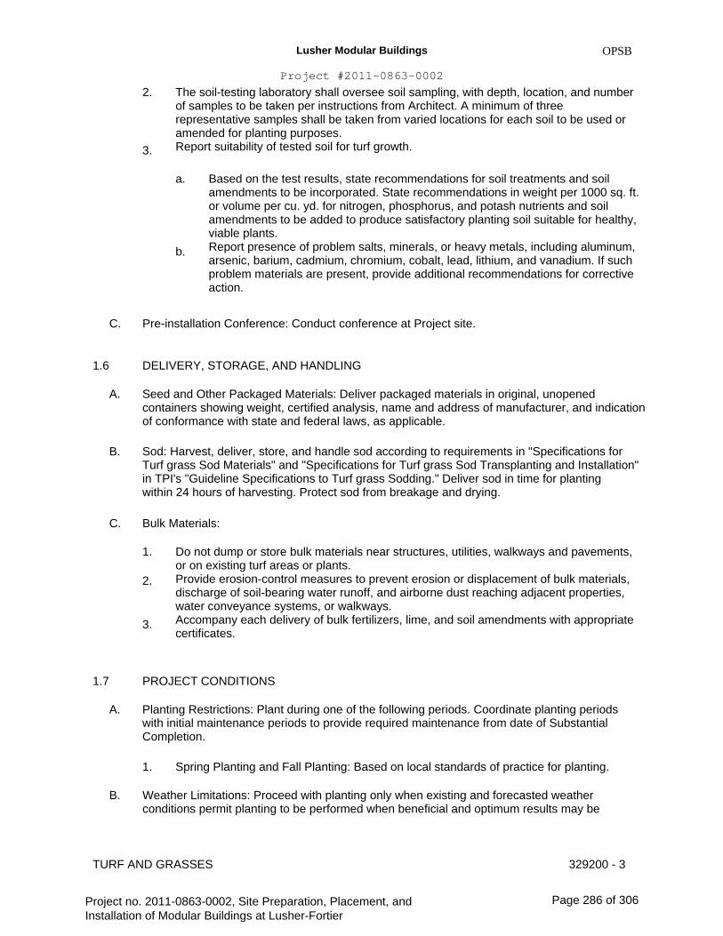
Lusher Modular Buildings
Project #2011-0863-0002
2.
OPSB
3.
The soil-testing laboratory shall oversee soil sampling, with depth, location, and number of samples to be taken per instructions from Architect. A minimum of three representative samples shall be taken from varied locations for each soil to be used or amended for planting purposes. Report suitability of tested soil for turf growth.
a. Based on the test results, state recommendations for soil treatments and soil amendments to be incorporated. State recommendations in weight per 1000 sq. ft. or volume per cu. yd. for nitrogen, phosphorus, and potash nutrients and soil amendments to be added to produce satisfactory planting soil suitable for healthy, viable plants. Report presence of problem salts, minerals, or heavy metals, including aluminum, arsenic, barium, cadmium, chromium, cobalt, lead, lithium, and vanadium. If such problem materials are present, provide additional recommendations for corrective action.
b.
C.
1.6
A.
Pre-installation Conference: Conduct conference at Project site.
DELIVERY, STORAGE, AND HANDLING
Seed and Other Packaged Materials: Deliver packaged materials in original, unopened containers showing weight, certified analysis, name and address of manufacturer, and indication of conformance with state and federal laws, as applicable.
Sod: Harvest, deliver, store, and handle sod according to requirements in "Specifications for Turf grass Sod Materials" and "Specifications for Turf grass Sod Transplanting and Installation" in TPI's "Guideline Specifications to Turf grass Sodding." Deliver sod in time for planting within 24 hours of harvesting. Protect sod from breakage and drying.
Bulk Materials:
1.
2.
Do not dump or store bulk materials near structures, utilities, walkways and pavements, or on existing turf areas or plants. Provide erosion-control measures to prevent erosion or displacement of bulk materials, discharge of soil-bearing water runoff, and airborne dust reaching adjacent properties, water conveyance systems, or walkways. Accompany each delivery of bulk fertilizers, lime, and soil amendments with appropriate certificates.
B.
C.
3.
1.7
A.
PROJECT CONDITIONS
Planting Restrictions: Plant during one of the following periods. Coordinate planting periods with initial maintenance periods to provide required maintenance from date of Substantial Completion.
1.
B.
Spring Planting and Fall Planting: Based on local standards of practice for planting.
Weather Limitations: Proceed with planting only when existing and forecasted weather conditions permit planting to be performed when beneficial and optimum results may be
TURF AND GRASSES 329200 - 3
Project no. 2011-0863-0002, Site Preparation, Placement, and Installation of Modular Buildings at Lusher-Fortier
Page 286 of 306
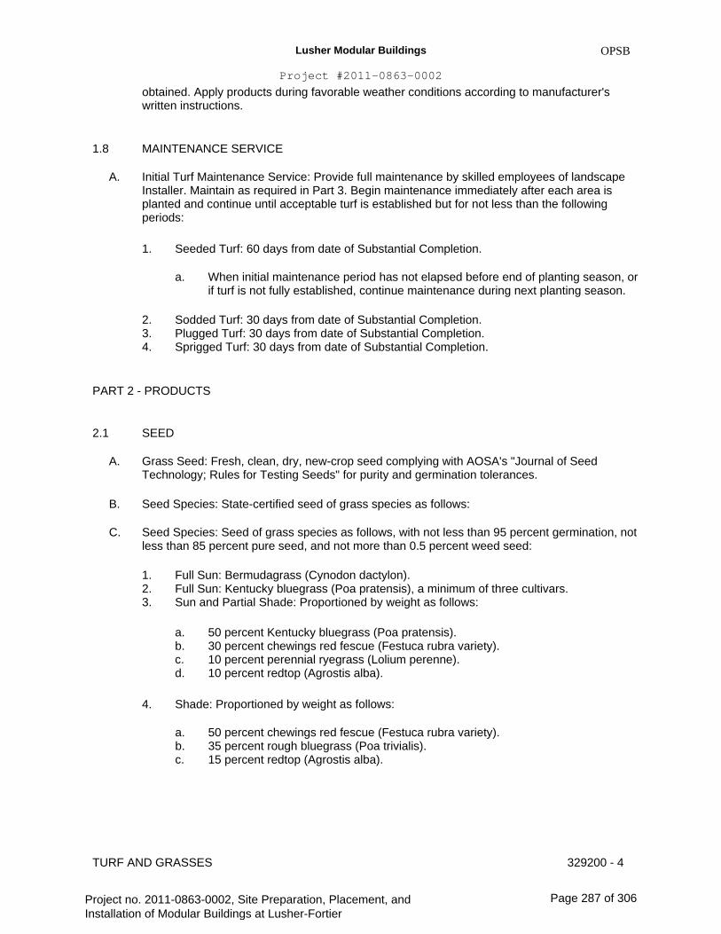
Lusher Modular Buildings
Project #2011-0863-0002
OPSB
obtained. Apply products during favorable weather conditions according to manufacturer's written instructions.
1.8
A.
MAINTENANCE SERVICE
Initial Turf Maintenance Service: Provide full maintenance by skilled employees of landscape Installer. Maintain as required in Part 3. Begin maintenance immediately after each area is planted and continue until acceptable turf is established but for not less than the following periods:
1. Seeded Turf: 60 days from date of Substantial Completion.
a.
2. 3. 4.
When initial maintenance period has not elapsed before end of planting season, or if turf is not fully established, continue maintenance during next planting season.
Sodded Turf: 30 days from date of Substantial Completion. Plugged Turf: 30 days from date of Substantial Completion. Sprigged Turf: 30 days from date of Substantial Completion.
PART 2 - PRODUCTS
2.1
A.
B.
C.
SEED
Grass Seed: Fresh, clean, dry, new-crop seed complying with AOSA's "Journal of Seed Technology; Rules for Testing Seeds" for purity and germination tolerances.
Seed Species: State-certified seed of grass species as follows:
Seed Species: Seed of grass species as follows, with not less than 95 percent germination, not less than 85 percent pure seed, and not more than 0.5 percent weed seed:
1. 2. 3.
Full Sun: Bermudagrass (Cynodon dactylon). Full Sun: Kentucky bluegrass (Poa pratensis), a minimum of three cultivars. Sun and Partial Shade: Proportioned by weight as follows:
a. b. c. d.
4.
50 percent Kentucky bluegrass (Poa pratensis). 30 percent chewings red fescue (Festuca rubra variety). 10 percent perennial ryegrass (Lolium perenne). 10 percent redtop (Agrostis alba).
Shade: Proportioned by weight as follows:
a. b. c.
50 percent chewings red fescue (Festuca rubra variety). 35 percent rough bluegrass (Poa trivialis). 15 percent redtop (Agrostis alba).
TURF AND GRASSES 329200 - 4
Project no. 2011-0863-0002, Site Preparation, Placement, and Installation of Modular Buildings at Lusher-Fortier
Page 287 of 306
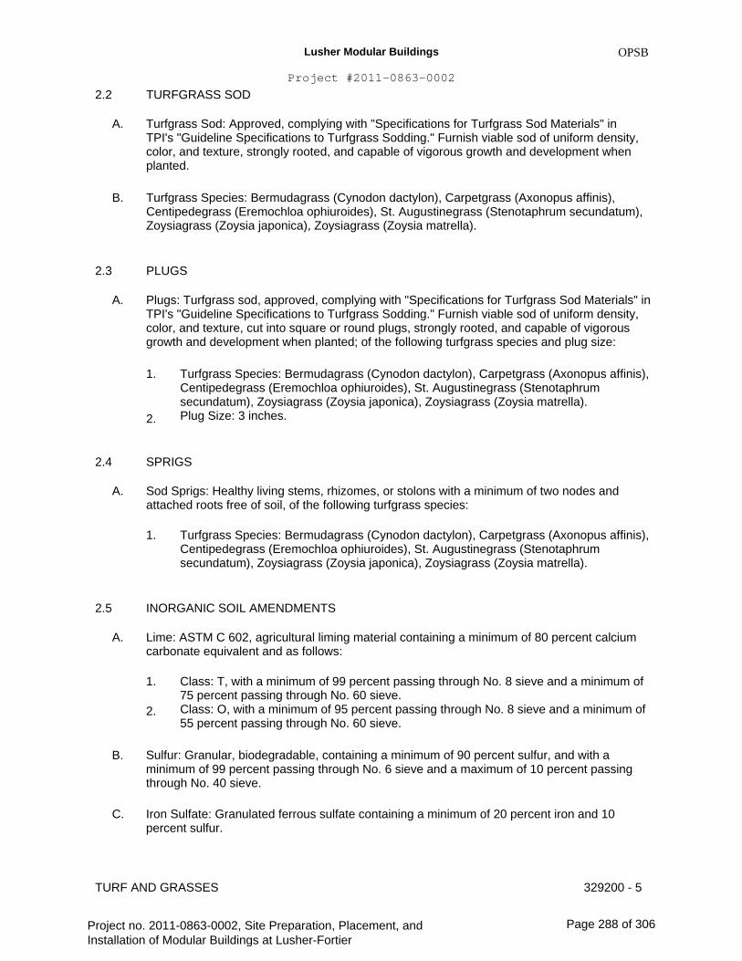
Lusher Modular Buildings
Project #2011-0863-0002
2.2
A.
TURFGRASS SOD
OPSB
Turfgrass Sod: Approved, complying with "Specifications for Turfgrass Sod Materials" in TPI's "Guideline Specifications to Turfgrass Sodding." Furnish viable sod of uniform density, color, and texture, strongly rooted, and capable of vigorous growth and development when planted.
Turfgrass Species: Bermudagrass (Cynodon dactylon), Carpetgrass (Axonopus affinis), Centipedegrass (Eremochloa ophiuroides), St. Augustinegrass (Stenotaphrum secundatum), Zoysiagrass (Zoysia japonica), Zoysiagrass (Zoysia matrella).
PLUGS
B.
2.3
A. Plugs: Turfgrass sod, approved, complying with "Specifications for Turfgrass Sod Materials" in TPI's "Guideline Specifications to Turfgrass Sodding." Furnish viable sod of uniform density, color, and texture, cut into square or round plugs, strongly rooted, and capable of vigorous growth and development when planted; of the following turfgrass species and plug size:
1. Turfgrass Species: Bermudagrass (Cynodon dactylon), Carpetgrass (Axonopus affinis), Centipedegrass (Eremochloa ophiuroides), St. Augustinegrass (Stenotaphrum secundatum), Zoysiagrass (Zoysia japonica), Zoysiagrass (Zoysia matrella). Plug Size: 3 inches. 2.
2.4
A.
SPRIGS
Sod Sprigs: Healthy living stems, rhizomes, or stolons with a minimum of two nodes and attached roots free of soil, of the following turfgrass species:
1. Turfgrass Species: Bermudagrass (Cynodon dactylon), Carpetgrass (Axonopus affinis), Centipedegrass (Eremochloa ophiuroides), St. Augustinegrass (Stenotaphrum secundatum), Zoysiagrass (Zoysia japonica), Zoysiagrass (Zoysia matrella).
2.5
A.
INORGANIC SOIL AMENDMENTS
Lime: ASTM C 602, agricultural liming material containing a minimum of 80 percent calcium carbonate equivalent and as follows:
1.
2.
B.
Class: T, with a minimum of 99 percent passing through No. 8 sieve and a minimum of 75 percent passing through No. 60 sieve. Class: O, with a minimum of 95 percent passing through No. 8 sieve and a minimum of 55 percent passing through No. 60 sieve.
Sulfur: Granular, biodegradable, containing a minimum of 90 percent sulfur, and with a minimum of 99 percent passing through No. 6 sieve and a maximum of 10 percent passing through No. 40 sieve.
Iron Sulfate: Granulated ferrous sulfate containing a minimum of 20 percent iron and 10 percent sulfur.
C.
TURF AND GRASSES 329200 - 5
Project no. 2011-0863-0002, Site Preparation, Placement, and Installation of Modular Buildings at Lusher-Fortier
Page 288 of 306

Lusher Modular Buildings
Project #2011-0863-0002
D.
E.
F.
G.
H.
I.
2.6
A.
Aluminum Sulfate: Commercial grade, unadulterated.
Perlite: Horticultural perlite, soil amendment grade.
Agricultural Gypsum: Minimum 90 percent calcium sulfate, finely ground with 90 percent passing through No. 50 sieve.
Sand: Clean, washed, natural or manufactured, and free of toxic materials.
Diatomaceous Earth: Calcined, 90 percent silica, with approximately 140 percent water absorption capacity by weight.
Zeolites: Mineral clinoptilolite with at least 60 percent water absorption by weight.
ORGANIC SOIL AMENDMENTS
Compost: Well-composted, stable, and weed-free organic matter, pH range of 5.5 to 8; moisture content 35 to 55 percent by weight; 100 percent passing through 1-inch sieve; soluble salt content of 5 to 10 decisiemens/m; not exceeding 0.5 percent inert contaminants and free of substances toxic to plantings; and as follows:
1. 2.
Organic Matter Content: 50 to 60 percent of dry weight. Feedstock: Agricultural, food, or industrial residuals; biosolids; yard trimmings; or source-separated or compostable mixed solid waste.
B.
C.
Sphagnum Peat: Partially decomposed sphagnum peat moss, finely divided or of granular texture, with a pH range of 3.4 to 4.8.
Muck Peat: Partially decomposed moss peat, native peat, or reed-sedge peat, finely divided or of granular texture, with a pH range of 6 to 7.5, and having a water-absorbing capacity of 1100 to 2000 percent.
Wood Derivatives: Decomposed, nitrogen-treated sawdust, ground bark, or wood waste; of uniform texture and free of chips, stones, sticks, soil, or toxic materials.
1. In lieu of decomposed wood derivatives, mix partially decomposed wood derivatives with ammonium nitrate at a minimum rate of 0.15 lb/cu. ft. of loose sawdust or ground bark, or with ammonium sulfate at a minimum rate of 0.25 lb/cu. ft. of loose sawdust or ground bark.
D.
E. Manure: Well-rotted, unleached, stable or cattle manure containing not more than 25 percent by volume of straw, sawdust, or other bedding materials; free of toxic substances, stones, sticks, soil, weed seed, and material harmful to plant growth.
FERTILIZERS 2.7
A. Commercial Fertilizer: Commercial-grade complete fertilizer of neutral character, consisting of fast- and slow-release nitrogen, 50 percent derived from natural organic sources of urea formaldehyde, phosphorous, and potassium in the following composition:
TURF AND GRASSES 329200 - 6
Project no. 2011-0863-0002, Site Preparation, Placement, and Installation of Modular Buildings at Lusher-Fortier
Page 289 of 306

Lusher Modular Buildings
Project #2011-0863-0002
1.
2.
B.
OPSB
Composition: 1 lb/1000 sq. ft. of actual nitrogen, 4 percent phosphorous, and 2 percent potassium, by weight. Composition: Nitrogen, phosphorous, and potassium in amounts recommended in soil reports from a qualified soil-testing laboratory.
Slow-Release Fertilizer: Granular or pelleted fertilizer consisting of 50 percent water-insoluble nitrogen, phosphorus, and potassium in the following composition:
1.
2.
Composition: 20 percent nitrogen, 10 percent phosphorous, and 10 percent potassium, by weight. Composition: Nitrogen, phosphorous, and potassium in amounts recommended in soil reports from a qualified soil-testing laboratory.
2.8
A.
PLANTING SOILS
Planting Soil : Existing, native surface topsoil formed under natural conditions with the duff layer retained during excavation process and stockpiled on-site. Verify suitability of native surface topsoil to produce viable planting soil. Clean soil of roots, plants, sod, stones, clay lumps, and other extraneous materials harmful to plant growth.
1. Supplement with another specified planting soil originating from a local approved source when quantities are insufficient.
2.9
A.
B.
C.
MULCHES
Straw Mulch: Provide air-dry, clean, mildew- and seed-free, salt hay or threshed straw of wheat, rye, oats, or barley.
Sphagnum Peat Mulch: Partially decomposed sphagnum peat moss, finely divided or of granular texture, and with a pH range of 3.4 to 4.8.
Muck Peat Mulch: Partially decomposed moss peat, native peat, or reed-sedge peat, finely divided or of granular texture, with a pH range of 6 to 7.5, and having a water-absorbing capacity of 1100 to 2000 percent.
Compost Mulch: Well-composted, stable, and weed-free organic matter, pH range of 5.5 to 8; moisture content 35 to 55 percent by weight; 100 percent passing through 1-inch sieve; soluble salt content of 2 to 5 decisiemens/m; not exceeding 0.5 percent inert contaminants and free of substances toxic to plantings; and as follows:
1. 2.
E.
Organic Matter Content: 50 to 60 percent of dry weight. Feedstock: Agricultural, food, or industrial residuals; biosolids; yard trimmings; or source-separated or compostable mixed solid waste.
D.
Fiber Mulch: Biodegradable, dyed-wood, cellulose-fiber mulch; nontoxic and free of plant- growth or germination inhibitors; with a maximum moisture content of 15 percent and a pH range of 4.5 to 6.5.
TURF AND GRASSES 329200 - 7
Project no. 2011-0863-0002, Site Preparation, Placement, and Installation of Modular Buildings at Lusher-Fortier
Page 290 of 306
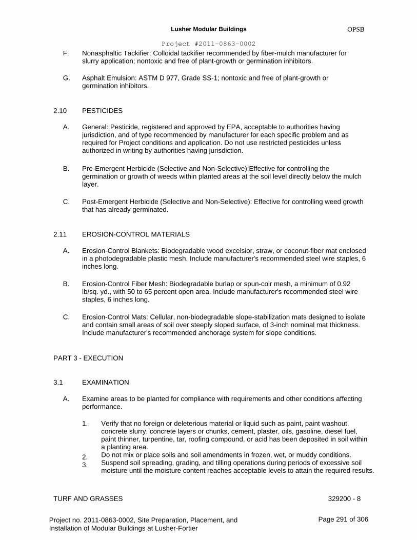
Lusher Modular Buildings
Project #2011-0863-0002
F.
G.
OPSB
Nonasphaltic Tackifier: Colloidal tackifier recommended by fiber-mulch manufacturer for slurry application; nontoxic and free of plant-growth or germination inhibitors.
Asphalt Emulsion: ASTM D 977, Grade SS-1; nontoxic and free of plant-growth or germination inhibitors.
PESTICIDES
General: Pesticide, registered and approved by EPA, acceptable to authorities having jurisdiction, and of type recommended by manufacturer for each specific problem and as required for Project conditions and application. Do not use restricted pesticides unless authorized in writing by authorities having jurisdiction.
Pre-Emergent Herbicide (Selective and Non-Selective):Effective for controlling the germination or growth of weeds within planted areas at the soil level directly below the mulch layer.
Post-Emergent Herbicide (Selective and Non-Selective): Effective for controlling weed growth that has already germinated.
EROSION-CONTROL MATERIALS
Erosion-Control Blankets: Biodegradable wood excelsior, straw, or coconut-fiber mat enclosed in a photodegradable plastic mesh. Include manufacturer's recommended steel wire staples, 6 inches long.
Erosion-Control Fiber Mesh: Biodegradable burlap or spun-coir mesh, a minimum of 0.92 lb/sq. yd., with 50 to 65 percent open area. Include manufacturer's recommended steel wire staples, 6 inches long.
Erosion-Control Mats: Cellular, non-biodegradable slope-stabilization mats designed to isolate and contain small areas of soil over steeply sloped surface, of 3-inch nominal mat thickness. Include manufacturer's recommended anchorage system for slope conditions.
2.10
A.
B.
C.
2.11
A.
B.
C.
PART 3 - EXECUTION
3.1
A.
EXAMINATION
Examine areas to be planted for compliance with requirements and other conditions affecting performance.
1. Verify that no foreign or deleterious material or liquid such as paint, paint washout, concrete slurry, concrete layers or chunks, cement, plaster, oils, gasoline, diesel fuel, paint thinner, turpentine, tar, roofing compound, or acid has been deposited in soil within a planting area. Do not mix or place soils and soil amendments in frozen, wet, or muddy conditions. Suspend soil spreading, grading, and tilling operations during periods of excessive soil moisture until the moisture content reaches acceptable levels to attain the required results.
329200 - 8
2. 3.
TURF AND GRASSES
Project no. 2011-0863-0002, Site Preparation, Placement, and Installation of Modular Buildings at Lusher-Fortier
Page 291 of 306
Lusher Modular Buildings
Project #2011-0863-0002
4.
B.
C.
OPSB
Uniformly moisten excessively dry soil that is not workable and which is too dusty.
Proceed with installation only after unsatisfactory conditions have been corrected.
If contamination by foreign or deleterious material or liquid is present in soil within a planting area, remove the soil and contamination as directed by Architect and replace with new planting soil.
PREPARATION 3.2
A. Protect structures, utilities, sidewalks, pavements, and other facilities, trees, shrubs, and plantings from damage caused by planting operations.
1. 2.
Protect adjacent and adjoining areas from hydroseeding and hydromulching overspray. Protect grade stakes set by others until directed to remove them.
B. Install erosion-control measures to prevent erosion or displacement of soils and discharge of soil-bearing water runoff or airborne dust to adjacent properties and walkways.
TURF AREA PREPARATION3.3
A.
B.
Limit turf subgrade preparation to areas to be planted.
Newly Graded Subgrades: Loosen subgrade to a minimum depth of 6 inches. Remove stones larger than 1 inch in any dimension and sticks, roots, rubbish, and other extraneous matter and legally dispose of them off Owner's property.
1.
2.
Apply fertilizer directly to subgrade before loosening as previously specified.
Spread planting soil to a depth of 6 inches not less than required to meet finish grades after light rolling and natural settlement. Do not spread if planting soil or subgrade is frozen, muddy, or excessively wet.
a.
b.
Spread approximately 1/2 the thickness of planting soil over loosened subgrade. Mix thoroughly into top 4 inches of subgrade. Spread remainder of planting soil. Reduce elevation of planting soil to allow for soil thickness of sod.
C. Unchanged Subgrades: If turf is to be planted in areas unaltered or undisturbed by excavating, grading, or surface-soil stripping operations, prepare surface soil as follows:
1. 2.
Remove existing grass, vegetation, and turf. Do not mix into surface soil. Loosen surface soil to a depth of at least 6 inches. Apply soil amendments and fertilizers according to planting soil mix proportions and mix thoroughly into top 4 inches of soil. Till soil to a homogeneous mixture of fine texture.
a.
3.
Apply fertilizer directly to surface soil before loosening.
Remove stones larger than 1 inch in any dimension and sticks, roots, trash, and other extraneous matter.
TURF AND GRASSES 329200 - 9
Project no. 2011-0863-0002, Site Preparation, Placement, and Installation of Modular Buildings at Lusher-Fortier
Page 292 of 306
Lusher Modular Buildings
Project #2011-0863-0002
4.
D.
OPSB
Legally dispose of waste material, including grass, vegetation, and turf, off Owner's property.
Finish Grading: Grade planting areas to a smooth, uniform surface plane with loose, uniformly fine texture. Grade to within plus or minus 1/2 inch of finish elevation. Roll and rake, remove ridges, and fill depressions to meet finish grades. Limit finish grading to areas that can be planted in the immediate future.
Moisten prepared area before planting if soil is dry. Water thoroughly and allow surface to dry before planting. Do not create muddy soil.
Before planting, obtain Architect's acceptance of finish grading; restore planting areas if eroded or otherwise disturbed after finish grading.
PREPARATION FOR EROSION-CONTROL MATERIALS
E.
F.
3.4
A.
B.
Prepare area as specified in "Turf Area Preparation" Article.
For erosion-control mats, install planting soil in two lifts, with second lift equal to thickness of erosion-control mats. Install erosion-control mat and fasten as recommended by material manufacturer.
Fill cells of erosion-control mat with planting soil and compact before planting.
For erosion-control blanket or mesh, install from top of slope, working downward, and as recommended by material manufacturer for site conditions. Fasten as recommended by material manufacturer.
Moisten prepared area before planting if surface is dry. Water thoroughly and allow surface to dry before planting. Do not create muddy soil.
SEEDING
C.
D.
E.
3.5
A. Sow seed with spreader or seeding machine. Do not broadcast or drop seed when wind velocity exceeds 5 mph. Evenly distribute seed by sowing equal quantities in two directions at right angles to each other.
1. 2.
Do not use wet seed or seed that is moldy or otherwise damaged. Do not seed against existing trees. Limit extent of seed to outside edge of planting saucer.
B.
C.
D.
E.
Sow seed at a total rate of 3 to 4 lb/1000 sq. ft.
Rake seed lightly into top 1/8 inch of soil, roll lightly, and water with fine spray.
Protect seeded areas with slopes exceeding 1:4 with erosion-control blankets installed and stapled according to manufacturer's written instructions.
Protect seeded areas with erosion-control mats where shown on Drawings; install and anchor according to manufacturer's written instructions.
TURF AND GRASSES 329200 - 10
Project no. 2011-0863-0002, Site Preparation, Placement, and Installation of Modular Buildings at Lusher-Fortier
Page 293 of 306

Lusher Modular Buildings
Project #2011-0863-0002
F.
OPSB
Protect seeded areas with slopes not exceeding 1:6 by spreading straw mulch. Spread uniformly at a minimum rate of 2 tons/acre to form a continuous blanket 1-1/2 inches in loose thickness over seeded areas. Spread by hand, blower, or other suitable equipment.
1. 2.
Anchor straw mulch by crimping into soil with suitable mechanical equipment. Bond straw mulch by spraying with asphalt emulsion at a rate of 10 to 13 gal./1000 sq. ft.. Take precautions to prevent damage or staining of structures or other plantings adjacent to mulched areas. Immediately clean damaged or stained areas.
G. Protect seeded areas from hot, dry weather or drying winds by applying compost mulch within 24 hours after completing seeding operations. Soak areas, scatter mulch uniformly to a thickness of 3/16 inch, and roll surface smooth.
HYDROSEEDING 3.6
A. Hydroseeding: Mix specified seed, fertilizer, and fiber mulch in water, using equipment specifically designed for hydroseed application. Continue mixing until uniformly blended into homogeneous slurry suitable for hydraulic application.
1. 2.
Mix slurry with asphalt-emulsion tackifier. Apply slurry uniformly to all areas to be seeded in a one-step process. Apply slurry at a rate so that mulch component is deposited at not less than 1500-lb/acre dry weight, and seed component is deposited at not less than the specified seed-sowing rate.
3.7
A.
B.
SODDING
Lay sod within 24 hours of harvesting. Do not lay sod if dormant or if ground is frozen or muddy.
Lay sod to form a solid mass with tightly fitted joints. Butt ends and sides of sod; do not stretch or overlap. Stagger sod strips or pads to offset joints in adjacent courses. Avoid damage to subgrade or sod during installation. Tamp and roll lightly to ensure contact with subgrade, eliminate air pockets, and form a smooth surface. Work sifted soil or fine sand into minor cracks between pieces of sod; remove excess to avoid smothering sod and adjacent grass.
1. 2.
Lay sod across angle of slopes exceeding 1:3. Anchor sod on slopes exceeding 1:6 with wood pegs or steel staples spaced as recommended by sod manufacturer but not less than 2 anchors per sod strip to prevent slippage.
C. Saturate sod with fine water spray within two hours of planting. During first week after planting, water daily or more frequently as necessary to maintain moist soil to a minimum depth of 1-1/2 inches below sod.
PLUGGING 3.8
A. Plant plugs in holes or furrows, spaced 12 inches apart in both directions. On slopes, contour furrows to near level.
TURF AND GRASSES 329200 - 11
Project no. 2011-0863-0002, Site Preparation, Placement, and Installation of Modular Buildings at Lusher-Fortier
Page 294 of 306
Lusher Modular Buildings
Project #2011-0863-0002
3.9
A.
SPRIGGING
OPSB
Plant freshly shredded sod sprigs in furrows 2-1/2 to 3 inches deep. Place individual sprigs with roots and portions of stem in moistened soil, 6 inches apart in rows 10 inches apart, and fill furrows without covering growing tips. Lightly roll and firm soil around sprigs after planting.
Broadcast sprigs uniformly over prepared surface at a rate of 10 cu. ft./1000 sq. ft. and mechanically force sprigs into lightly moistened soil.
1. 2. 3.
Spread a 1/4-inch- thick layer of compost mulch on sprigs. Lightly roll and firm soil around sprigs after planting. Water sprigs immediately after planting and keep moist by frequent watering until well rooted.
B.
3.10
A.
B.
TURF RENOVATION
Renovate existing turf.
Renovate existing turf damaged by Contractor's operations, such as storage of materials or equipment and movement of vehicles.
1.
2.
Reestablish turf where settlement or washouts occur or where minor regrading is required. Install new planting soil as required.
C.
D.
Remove sod and vegetation from diseased or unsatisfactory turf areas; do not bury in soil.
Remove topsoil containing foreign materials such as oil drippings, fuel spills, stones, gravel, and other construction materials resulting from Contractor's operations, and replace with new planting soil.
Mow, dethatch, core aerate, and rake existing turf.
Remove weeds before seeding. Where weeds are extensive, apply selective herbicides as required. Do not use pre-emergence herbicides.
Remove waste and foreign materials, including weeds, soil cores, grass, vegetation, and turf, and legally dispose of them off Owner's property.
Till stripped, bare, and compacted areas thoroughly to a soil depth of 6 inches.
Apply soil amendments and initial fertilizers required for establishing new turf and mix thoroughly into top 4 inches of existing soil. Install new planting soil to fill low spots and meet finish grades.
Apply seed and protect with straw mulch as required for new turf.
Water newly planted areas and keep moist until new turf is established.
E.
F.
G.
H.
I.
J.
K.
TURF AND GRASSES 329200 - 12
Project no. 2011-0863-0002, Site Preparation, Placement, and Installation of Modular Buildings at Lusher-Fortier
Page 295 of 306
Lusher Modular Buildings
Project #2011-0863-0002
3.11
A.
TURF MAINTENANCE
OPSB
Maintain and establish turf by watering, fertilizing, weeding, mowing, trimming, replanting, and performing other operations as required to establish healthy, viable turf. Roll, regrade, and replant bare or eroded areas and remulch to produce a uniformly smooth turf. Provide materials and installation the same as those used in the original installation.
1.
2.
3.
Fill in as necessary soil subsidence that may occur because of settling or other processes. Replace materials and turf damaged or lost in areas of subsidence. In areas where mulch has been disturbed by wind or maintenance operations, add new mulch and anchor as required to prevent displacement. Apply treatments as required to keep turf and soil free of pests and pathogens or disease. Use integrated pest management practices whenever possible to minimize the use of pesticides and reduce hazards.
B. Watering: Install and maintain temporary piping, hoses, and turf-watering equipment to convey water from sources and to keep turf uniformly moist to a depth of 4 inches.
1. Schedule watering to prevent wilting, puddling, erosion, and displacement of seed or mulch. Lay out temporary watering system to avoid walking over muddy or newly planted areas. Water turf with fine spray at a minimum rate of 1 inch per week unless rainfall precipitation is adequate.
2.
C. Mow turf as soon as top growth is tall enough to cut. Repeat mowing to maintain specified height without cutting more than 1/3 of grass height. Remove no more than 1/3 of grass-leaf growth in initial or subsequent mowings. Do not delay mowing until grass blades bend over and become matted. Do not mow when grass is wet.
Turf Postfertilization: Apply fertilizer after initial mowing and when grass is dry.
1. Use fertilizer that will provide actual nitrogen of at least 1 lb/1000 sq. ft. to turf area.
D.
3.12
A.
SATISFACTORY TURF
Turf installations shall meet the following criteria as determined by Architect:
1. Satisfactory Seeded Turf: At end of maintenance period, a healthy, uniform, close stand of grass has been established, free of weeds and surface irregularities, with coverage exceeding 90 percent over any 10 sq. ft. and bare spots not exceeding 5 by 5 inches. Satisfactory Sodded Turf: At end of maintenance period, a healthy, well-rooted, even- colored, viable turf has been established, free of weeds, open joints, bare areas, and surface irregularities. Satisfactory Plugged Turf: At end of maintenance period, the required number of plugs has been established as well-rooted, viable patches of grass, and areas between plugs are free of weeds and other undesirable vegetation. Satisfactory Sprigged Turf: At end of maintenance period, the required number of sprigs has been established as well-rooted, viable plants, and areas between sprigs are free of weeds and other undesirable vegetation.
2.
3.
4.
TURF AND GRASSES 329200 - 13
Project no. 2011-0863-0002, Site Preparation, Placement, and Installation of Modular Buildings at Lusher-Fortier
Page 296 of 306
Lusher Modular Buildings
Project #2011-0863-0002
B.
OPSB
Use specified materials to reestablish turf that does not comply with requirements and continue maintenance until turf is satisfactory.
PESTICIDE APPLICATION
Apply pesticides and other chemical products and biological control agents in accordance with requirements of authorities having jurisdiction and manufacturer's written recommendations. Coordinate applications with Owner's operations and others in proximity to the Work. Notify Owner before each application is performed.
Post-Emergent Herbicides (Selective and Non-Selective): Apply only as necessary to treat already-germinated weeds and in accordance with manufacturer's written recommendations.
CLEANUP AND PROTECTION
Promptly remove soil and debris created by turf work from paved areas. Clean wheels of vehicles before leaving site to avoid tracking soil onto roads, walks, or other paved areas.
Erect temporary fencing or barricades and warning signs as required to protect newly planted areas from traffic. Maintain fencing and barricades throughout initial maintenance period and remove after plantings are established.
Remove nondegradable erosion-control measures after grass establishment period.
3.13
A.
B.
3.14
A.
B.
C.
END OF SECTION 329200
TURF AND GRASSES 329200 - 14
Project no. 2011-0863-0002, Site Preparation, Placement, and Installation of Modular Buildings at Lusher-Fortier
Page 297 of 306

Lusher Modular Buildings
Project #2011-0863-0002
OPSB
SECTION 334100 - STORM UTILITY DRAINAGE PIPING
PART 1 - GENERAL
1.1
A.
RELATED DOCUMENTS
Drawings and general provisions of the Contract, including General and Supplementary Conditions and Division 01 Specification Sections, apply to this Section.
SUMMARY
A. Section Includes:
1. 2. 3. 4. 5. 6. 7. 8. 9. 10. 11. 12. 13. 14. 15. 16.
1.3
A.
1.4
A.
B.
Pipe and fittings. Non-pressure transition couplings. Pressure pipe couplings. Expansion joints and deflection fittings. Backwater valves. Cleanouts. Drains. Encasement for piping. Manholes. Channel drainage systems. Catch basins. Storm water inlets. Storm water detention structures. Pipe outlets. Dry wells. Storm water disposal systems.
1.2
DEFINITIONS
FRP: Fiberglass-reinforced plastic.
SUBMITTALS
Product Data: For each type of product indicated.
Shop Drawings:
1. 2.
Manholes: Include plans, elevations, sections, details, frames, and covers. Catch basins & storm water inlets. Include plans, elevations, sections, details, frames, covers, and grates.
STORM UTILITY DRAINAGE PIPING 334100 - 1
Project no. 2011-0863-0002, Site Preparation, Placement, and Installation of Modular Buildings at Lusher-Fortier
Page 298 of 306
Lusher Modular Buildings
Project #2011-0863-0002
C.
OPSB
Coordination Drawings: Show pipe sizes, locations, and elevations. Show other piping in same trench and clearances from storm drainage system piping. Indicate interface and spatial relationship between manholes, piping, and proximate structures.
Profile Drawings: Show system piping in elevation. Draw profiles at horizontal scale of not less than 1 inch equals 50 feet and vertical scale of not less than 1 inch equals 5 feet. Indicate manholes and piping. Show types, sizes, materials, and elevations of other utilities crossing system piping.
Field quality-control reports.
DELIVERY, STORAGE, AND HANDLING
D.
E.
1.5
A.
B.
C.
D.
Do not store plastic manholes, pipe, and fittings in direct sunlight.
Protect pipe, pipe fittings, and seals from dirt and damage.
Handle manholes according to manufacturer's written rigging instructions.
Handle catch basins and storm water inlets according to manufacturer's written rigging instructions.
PROJECT CONDITIONS 1.6
A. Interruption of Existing Storm Drainage Service: Do not interrupt service to facilities occupied by Owner or others unless permitted under the following conditions and then only after arranging to provide temporary service according to requirements indicated:
1.
2.
Notify Construction Manager & Owner no fewer than two days in advance of proposed interruption of service. Do not proceed with interruption of service without Construction Manager's & Owner's written permission.
PART 2 - PRODUCTS
2.1
A.
CONCRETE PIPE AND FITTINGS
Non-reinforced-Concrete Sewer Pipe and Fittings: ASTM C 14 (ASTM C 14M), Class 3, with bell-and-spigot or tongue-and-groove ends and gasketed joints with ASTM C 443 (ASTM C 443M), rubber gaskets.
Reinforced-Concrete Sewer Pipe and Fittings: ASTM C 76 (ASTM C 76M).
MANHOLES
A. Standard Precast Concrete Manholes:
B.
2.2
STORM UTILITY DRAINAGE PIPING 334100 - 2
Project no. 2011-0863-0002, Site Preparation, Placement, and Installation of Modular Buildings at Lusher-Fortier
Page 299 of 306
Lusher Modular Buildings
Project #2011-0863-0002
1.
2. 3.
4.
5. 6.
7. 8.
9.
OPSB
10.
11.
Description: ASTM C 478 (ASTM C 478M), precast, reinforced concrete, of depth indicated, with provision for sealant joints. Diameter: 48 inches minimum unless otherwise indicated. Ballast: Increase thickness of precast concrete sections or add concrete to base section as required to prevent flotation. Base Section: 6-inch minimum thickness for floor slab and 4-inch minimum thickness for walls and base riser section, and separate base slab or base section with integral floor. Riser Sections: 4-inch minimum thickness and lengths to provide depth indicated. Top Section: Eccentric-cone type unless concentric-cone or flat-slab-top type is indicated, and top of cone of size that matches grade rings. Joint Sealant: ASTM C 990 (ASTM C 990M), bitumen or butyl rubber. Resilient Pipe Connectors: ASTM C 923 (ASTM C 923M), cast or fitted into manhole walls, for each pipe connection. Steps: As detailed in the plans, wide enough to allow worker to place both feet on one step and designed to prevent lateral slippage off step. Cast or anchor steps into sidewalls at 12- to 16-inch intervals. Omit steps if total depth from floor of manhole to finished grade is less than 60 inches. Adjusting Rings: Interlocking HDPE rings with level or sloped edge in thickness and diameter matching manhole frame and cover, and of height required to adjust manhole frame and cover to indicated elevation and slope. Include sealant recommended by ring manufacturer. Grade Rings: Reinforced-concrete rings, 6- to 9-inch total thickness, to match diameter of manhole frame and cover, and height as required to adjust manhole frame and cover to indicated elevation and slope.
B. Designed Precast Concrete Manholes:
1. Description:ASTM C 913; designed according to ASTM C 890 for A-16 (AASHTO HS20-44), heavy-traffic, structural loading; of depth, shape, and dimensions indicated, with provision for sealant joints. Ballast: Increase thickness of one or more precast concrete sections or add concrete to manhole as required to prevent flotation. Joint Sealant: ASTM C 990 (ASTM C 990M), bitumen or butyl rubber. Resilient Pipe Connectors: ASTM C 923 (ASTM C 923M), cast or fitted into manhole walls, for each pipe connection. Steps: As detailed in the plans, wide enough to allow worker to place both feet on one step and designed to prevent lateral slippage off step. Cast or anchor steps into sidewalls at 12- to 16-inch intervals. Omit steps if total depth from floor of manhole to finished grade is less than 60 inches. Adjusting Rings: Interlocking HDPE rings with level or sloped edge in thickness and diameter matching manhole frame and cover, and of height required to adjust manhole frame and cover to indicated elevation and slope. Include sealant recommended by ring manufacturer. Grade Rings: Reinforced-concrete rings, 6- to 9-inch total thickness, to match diameter of manhole frame and cover, and of height required to adjust manhole frame and cover to indicated elevation and slope.
2.
3. 4.
5.
6.
7.
C. Manhole Frames and Covers:
STORM UTILITY DRAINAGE PIPING 334100 - 3
Project no. 2011-0863-0002, Site Preparation, Placement, and Installation of Modular Buildings at Lusher-Fortier
Page 300 of 306

Lusher Modular Buildings
Project #2011-0863-0002
Copyright 2007 AIA
1.
MASTERSPEC Full Length OPSB
2.
2.3
A.
Description: Ferrous; 24-inch ID by 7- to 9-inch riser with 4-inch- minimum width flange and 26-inch- diameter cover. Include indented top design with lettering cast into cover, using wording equivalent to "STORM SEWER." Material: ASTM A 536, Grade 60-40-18 ductile iron unless otherwise indicated.
CONCRETE
General: Cast-in-place concrete according to ACI 318, ACI 350/350R (ACI 350M/350RM), and the following:
1. 2. 3. 4.
B.
Cement: ASTM C 150, Type II. Fine Aggregate: ASTM C 33, sand. Coarse Aggregate: ASTM C 33, crushed gravel. Water: Potable.
Portland Cement Design Mix: 4000 psi minimum, with 0.45 maximum water/cementitious materials ratio.
1. 2.
Reinforcing Fabric: ASTM A 185/A 185M, steel, welded wire fabric, plain. Reinforcing Bars: ASTM A 615/A 615M, Grade 60 (420 MPa) deformed steel.
C. Manhole Channels and Benches: Factory or field formed from concrete. Portland cement design mix, 4000 psi minimum, with 0.45 maximum water/cementitious materials ratio. Include channels and benches in manholes.
1. Channels: Concrete invert, formed to same width as connected piping, with height of vertical sides to three-fourths of pipe diameter. Form curved channels with smooth, uniform radius and slope.
a.
2.
Invert Slope: 1 percent through manhole.
Benches: Concrete, sloped to drain into channel.
a. Slope: 4 percent.
D. Ballast and Pipe Supports: Portland cement design mix, 3000 psi minimum, with 0.58 maximum water/cementitious materials ratio.
1. 2.
Reinforcing Fabric: ASTM A 185/A 185M, steel, welded wire fabric, plain. Reinforcing Bars: ASTM A 615/A 615M, Grade 60 (420 MPa) deformed steel.
2.4
A.
B.
STORMWATER INLETS
Curb Inlets: Made with vertical curb opening, of materials and dimensions according to the plans.
Gutter Inlets: Made with horizontal gutter opening, of materials and dimensions according to the plans. Include heavy-duty frames and grates.
STORM UTILITY DRAINAGE PIPING 334100 - 4
Project no. 2011-0863-0002, Site Preparation, Placement, and Installation of Modular Buildings at Lusher-Fortier
Page 301 of 306
Lusher Modular Buildings
Project #2011-0863-0002
C.
D.
OPSB
Combination Inlets: Made with vertical curb and horizontal gutter openings, of materials and dimensions according to the plans. Include heavy-duty frames and grates.
Frames and Grates: Heavy duty.
PART 3 - EXECUTION
3.1
A.
3.2
A.
EARTHWORK
Excavation, trenching, and backfilling are specified in Division 31 Section "Earth Moving."
PIPING INSTALLATION
General Locations and Arrangements: Drawing plans and details indicate general location and arrangement of underground storm drainage piping. Location and arrangement of piping layout take into account design considerations. Install piping as indicated, to extent practical. Where specific installation is not indicated, follow piping manufacturer's written instructions.
Install piping beginning at low point, true to grades and alignment indicated with unbroken continuity of invert. Place bell ends of piping facing upstream. Install gaskets, seals, sleeves, and couplings according to manufacturer's written instructions for use of lubricants, cements, and other installation requirements.
Install manholes for changes in direction unless fittings are indicated.
Install gravity-flow, non-pressure drainage piping according to the following:
1. 2.
E.
3.3
A.
Install piping pitched down in direction of flow. Install reinforced-concrete sewer piping according to ASTM C 1479 and ACPA's "Concrete Pipe Installation Manual."
B.
C.
D.
Install force-main pressure piping according to the following:
PIPE JOINT CONSTRUCTION
Join gravity-flow, nonpressure drainage piping according to the following: 1.Join reinforced-concrete sewer piping according to ACPA's "Concrete Pipe Installation Manual" for rubber-gasketed joints.
DRAIN INSTALLATION 3.4
A.
B.
C.
Install type of drains in locations indicated. 1.Use Heavy-Duty, top-loading classification drains in vehicle-traffic service areas.
Fasten grates to drains if indicated.
Set drain frames and covers with tops flush with pavement surface.
STORM UTILITY DRAINAGE PIPING 334100 - 5
Project no. 2011-0863-0002, Site Preparation, Placement, and Installation of Modular Buildings at Lusher-Fortier
Page 302 of 306
Lusher Modular Buildings
Project #2011-0863-0002
D.
3.5
A.
B.
C.
D.
OPSB
Embed trench sections in 4-inch minimum concrete around bottom and sides.
MANHOLE INSTALLATION
General: Install manholes, complete with appurtenances and accessories indicated.
Install precast concrete manhole sections with sealants according to ASTM C 891.
Where specific manhole construction is not indicated, follow manhole manufacturer's written instructions.
Set tops of frames and covers flush with finished surface of manholes that occur in pavements. Set tops 3 inches above finished surface elsewhere unless otherwise indicated.
STORMWATER INLET AND OUTLET INSTALLATION 3.6
A.
B.
C.
D.
E.
3.7
A.
3.8
A.
Construct inlet head walls, aprons, and sides of reinforced concrete, as indicated.
Construct riprap of broken stone, as indicated.
Install outlets that spill onto grade, anchored with concrete, where indicated.
Install outlets that spill onto grade, with flared end sections that match pipe, where indicated.
Construct energy dissipaters at outlets, as indicated.
CONCRETE PLACEMENT
Place cast-in-place concrete according to ACI 318.
FIELD QUALITY CONTROL
Inspect interior of piping to determine whether line displacement or other damage has occurred. Inspect after approximately 24 inches of backfill is in place, and again at completion of Project.
1. 2.
Submit separate reports for each system inspection. Defects requiring correction include the following:
a. b.
c. d. e.
3.
4.
Alignment: Less than full diameter of inside of pipe is visible between structures. Deflection: Flexible piping with deflection that prevents passage of ball or cylinder of size not less than 92.5 percent of piping diameter. Damage: Crushed, broken, cracked, or otherwise damaged piping. Infiltration: Water leakage into piping. Exfiltration: Water leakage from or around piping.
Replace defective piping using new materials, and repeat inspections until defects are within allowances specified. Re-inspect and repeat procedure until results are satisfactory.
STORM UTILITY DRAINAGE PIPING 334100 - 6
Project no. 2011-0863-0002, Site Preparation, Placement, and Installation of Modular Buildings at Lusher-Fortier
Page 303 of 306

Lusher Modular Buildings
Project #2011-0863-0002
B.
OPSB
Test new piping systems, and parts of existing systems that have been altered, extended, or repaired, for leaks and defects.
1. 2.
3.
4. 5.
Do not enclose, cover, or put into service before inspection and approval. Test completed piping systems according to requirements of authorities having jurisdiction. Schedule tests and inspections by authorities having jurisdiction with at least 24 hours' advance notice. Submit separate report for each test. Gravity-Flow Storm Drainage Piping: Test according to requirements of authorities having jurisdiction, UNI-B-6, and the following:
a.
b. c.
Exception: Piping with soiltight joints unless required by authorities having jurisdiction. Option: Test plastic piping according to ASTM F 1417. Option: Test concrete piping according to ASTM C 924 (ASTM C 924M).
C. Replace leaking piping using new materials, and repeat testing until leakage is within allowances specified.
CLEANING 3.9
A. Clean interior of piping of dirt and superfluous materials. Flush with water.
END OF SECTION 334100
STORM UTILITY DRAINAGE PIPING 334100 - 7
Project no. 2011-0863-0002, Site Preparation, Placement, and Installation of Modular Buildings at Lusher-Fortier
Page 304 of 306

Lusher Modular Buildings
Project #2011-0863-0002
OPSB
SECTION 334600 - SUBDRAINAGE
PART 1 - GENERAL
1.1
A.
RELATED DOCUMENTS
Drawings and general provisions of the Contract, including General and Supplementary Conditions and Division 01 Specification Sections, apply to this Section.
SUMMARY
A. Section Includes: 1.Geotextile filter fabrics.
SUBMITTALS
A. Product Data: 1.Geotextile filter fabrics.
1.2
1.3
PART 2 - PRODUCTS
2.1
A.
B.
GEOTEXTILE FILTER FABRICS
Description: Fabric of PP or polyester fibers or combination of both, with flow rate range from 110 to 330 gpm/sq. ft when tested according to ASTM D 4491.
Structure Type: Nonwoven, needle-punched continuous filament.
1. 2.
Survivability: AASHTO M 288 Class 2. Styles: Flat and sock.
PART 3 - EXECUTION
3.1
A.
B.
EXAMINATION
Examine surfaces and areas for suitable conditions where subdrainage systems are to be installed.
If subdrainage is required for landscaping, locate and mark existing utilities, underground structures, and aboveground obstructions before beginning installation and avoid disruption and damage of services.
Proceed with installation only after unsatisfactory conditions have been corrected. C.
SUBDRAINAGE 334600 - 1
Project no. 2011-0863-0002, Site Preparation, Placement, and Installation of Modular Buildings at Lusher-Fortier
Page 305 of 306
Lusher Modular Buildings
Project #2011-0863-0002
3.2
A.
3.3
A.
B.
EARTHWORK
OPSB
Excavating, trenching, and backfilling are specified in Division 31 Section "Earth Moving."
FOUNDATION DRAINAGE INSTALLATION
Lay flat-style geotextile filter fabric in trench and overlap trench sides.
Place supporting layer of drainage course over compacted subgrade and geotextile filter fabric, to compacted depth of not less than 4 inches.
IDENTIFICATION 3.4
A. Arrange for installation of green warning tapes directly over piping. Comply with requirements for underground warning tapes specified in specified in Division 31 Section "Earth Moving."
1. 2.
Install PE warning tape or detectable warning tape over ferrous piping. Install detectable warning tape over nonferrous piping and over edges of underground structures.
3.5
A.
FIELD QUALITY CONTROL
Tests and Inspections:
1.
B.
C.
Perform tests and inspections as specified by manufacturer.
Drain piping will be considered defective if it does not pass tests and inspections.
Prepare test and inspection reports.
END OF SECTION 334600
SUBDRAINAGE 334600 - 2
Project no. 2011-0863-0002, Site Preparation, Placement, and Installation of Modular Buildings at Lusher-Fortier
Page 306 of 306