Project Design Plan - ia.cpuc.ca.gov
16
FINAL Project Design Plan West of Devers Upgrade Project Riverside and San Bernardino Counties, California Prepared for Southern California Edison July 2017 Prepared by 6 Hutton Centre Drive Suite 700 Santa Ana, CA 92707
Transcript of Project Design Plan - ia.cpuc.ca.gov
F INAL
Project Design Plan
West of Devers Upgrade Project Riverside and San Bernardino Counties, California
Prepared for
Southern California Edison
July 2017
Prepared by
6 Hutton Centre Drive Suite 700 Santa Ana, CA 92707

PR0509171553SCO
Project Design Plan Checklist Applicable Agencies:
Bureau of Indian Affairs Coachella Valley Conservation Commission
Bureau of Land Management Morongo Band of Mission Indians California Department of Fish and Wildlife Riverside County Regional Conservation Authority California Public Utilities Commission U.S. Fish and Wildlife Service
Applies in the Following Areas: BLM Lands CV-MSHCP
Morongo Reservation WR-MSHCP
San Bernardino County
Applies to the Following Project Components: Transmission Line Subtransmission Telecom
Substations Distribution
Construction Yards
Addresses the Following Measure:
FEIR/FEIS MM VR-8a Minimize visual contrast in project design Incorporates the Requirements of the Following Measures, where applicable: FEIR/FEIS MM VR-1a Screen construction activities from view
FEIR/FEIS MM VR-2a Minimize vegetation removal and ground disturbance
FEIR/FEIS MM VR-3a Reduce color contrast of retaining walls, land scars, and graveled areas
FEIR/FEIS MM VR-4a Minimize in-line views of retaining walls and land scars
FEIR/FEIS MM VR-5a Prohibit construction marking of natural features
PR0509171553SCO III
Contents Section Page
Acronyms and Abbreviations .............................................................................................................. v
1 Introduction ....................................................................................................................... 1-1 1.1 Project Overview .............................................................................................................. 1-1 1.2 Project Location ............................................................................................................... 1-2 1.3 Lead Agencies .................................................................................................................. 1-3 1.4 Mitigation Measure ......................................................................................................... 1-3 1.5 Applicable Project Segments ........................................................................................... 1-4 1.6 Timing .............................................................................................................................. 1-5
2 Methods ............................................................................................................................. 2-1 2.1.1 Design Considerations ........................................................................................ 2-1 2.1.2 Coordination with Local Governments ............................................................... 2-2
3 Plan Approval ..................................................................................................................... 3-1
4 References .......................................................................................................................... 4-1
5 Revisions ............................................................................................................................ 5-1
Tables
1-1a Applicable Mitigation Measure..................................................................................................... 1-3 1-1b Incorporated Mitigation Measures ............................................................................................... 1-3 1-2 Applicable Timing .......................................................................................................................... 1-5 Figure
1-1 Project Location Map

PR0509171553SCO V
Acronyms and Abbreviations BLM Bureau of Land Management
CPCN Certificate of Public Convenience and Necessity
CPUC California Public Utilities Commission
FEIR Final Environmental Impact Report
FEIS Final Environmental Impact Statement
HRRP Habitat Restoration and Revegetation Plan
kV kilovolts
MM mitigation measure
Plan Project Design Plan
Project West of Devers Upgrade Project
ROW right-of-way
SCE Southern California Edison
SR State Route
WOD West of Devers
SECTION 1
PR0509171553SCO 1-1
Introduction Southern California Edison (SCE) proposes to construct the West of Devers (WOD) Upgrade Project (Project) to increase the power transfer capability of the WOD 220-kilovolt (kV) transmission lines between Devers, El Casco, Vista, and San Bernardino substations. The Project is needed to facilitate the full deliverability of new electric generation resources being developed in eastern Riverside County, in an area designated by the California Independent System Operator for planning purposes as the Blythe and Desert Center areas. The Project, planned to be operational by 2021, would upgrade the existing WOD transmission line system by replacing the existing WOD 220-kV transmission lines and associated structures with higher-capacity transmission lines and structures and making telecommunication improvements.
This Project Design Plan (Plan) has been prepared in compliance with mitigation measure (MM) VR-8a from the Final Environmental Impact Report1 (FEIR) (California Public Utilities Commission [CPUC], 2015), Addendum to the FEIR (CPUC, 2016a), and Final Environmental Impact Statement (FEIS) (Bureau of Land Management [BLM], 2016a) as presented in the Certificate of Public Convenience and Necessity (CPCN) (California Public Utilities Commission [CPUC], 2016b) and Record of Decision (BLM, 2016b), respectively. Compliance with MM VR-8a will reduce the visual contrast of new structures and components by using design fundamentals to blend project elements with the characteristic of the existing landscape.
MM VR-1a: Screen Construction Activities from View; MM VR-2a: Minimize Vegetation Removal and Ground Disturbance; MM V-3a: Reduce Color Contrast of Retaining Walls, Land Scars, and Graveled Areas; MM VR-4a: Minimize In-line Views of Retaining Walls and Land Scars; and MM VR-5a: Prohibit Construction Marking of Natural Features do not require the preparation of plans. However, because the MMs directly relate to minimizing visual impacts during the project design, these mitigation measures are incorporated into or referenced in following sections, as applicable.
1.1 Project Overview The Project would upgrade the existing WOD system by replacing existing 220-kV transmission lines and associated structures with new, higher-capacity 220-kV transmission lines and structures, modifying existing substation facilities, removing and relocating existing subtransmission (66-kV) lines, removing and relocating existing distribution (12-kV) lines, and making various telecommunication improvements. In particular, the Project would:
• Upgrade substation equipment within SCE’s existing Devers, El Casco, Etiwanda, San Bernardino, and Vista substations to accommodate continuous and emergency power on the upgraded WOD 220-kV transmission lines. Activities related to substation upgrades will take place within the existing, disturbed fence lines of the substations and are not addressed further in this Plan.
• Remove and upgrade the existing 220-kV transmission lines and structures primarily within the existing WOD corridor as follows:
− Segment 1 would be approximately 3.5 miles long and extend south from San Bernardino Substation to the San Bernardino Junction. It would include the following existing 220-kV transmission lines: Devers─San Bernardino, Etiwanda─San Bernardino, San Bernardino─Vista, and El Casco─San Bernardino.
1 For the purpose of this Plan, “FEIR” refers to the FEIR (California Public Utilities Commission [CPUC], 2015) and Addendum to the FEIR (CPUC, 2016a).

SECTION 1 – INTRODUCTION
1-2 PR0509171553SCO
− Segment 2 would be approximately 5 miles long and extend west from the San Bernardino Junction to Vista Substation. It would include the following existing 220-kV transmission lines: Devers─Vista No. 1 and Devers─Vista No. 2.
− Segment 3 would be approximately 10 miles long and extend east from the San Bernardino Junction to El Casco Substation. It would include the following existing 220-kV transmission lines: Devers─Vista No. 1, Devers─Vista No. 2, El Casco─San Bernardino, and Devers–San Bernardino.
− Segment 4 would be approximately 12 miles long and extend east from the El Casco Substation to San Gorgonio Avenue in the City of Banning. It would include the following existing 220-kV transmission lines: Devers─Vista No. 1, Devers─Vista No. 2, Devers─El Casco, and Devers─San Bernardino.
− Segment 5 would be approximately 9 miles long and extend east from San Gorgonio Avenue in the City of Banning to the eastern limit of the Morongo Band of Mission Indians (Morongo Reservation) at Rushmore Avenue. It would include the following existing 220-kV transmission lines: Devers─Vista No. 1, Devers─Vista No. 2, Devers─El Casco, and Devers─San Bernardino.
− Segment 6 would be approximately 8 miles long and extend east from the eastern boundary of the Morongo Reservation to Devers Substation. It would include the following existing 220-kV transmission lines: Devers─Vista No. 1, Devers─Vista No. 2, Devers─El Casco, and Devers─San Bernardino.
• Remove a portion (approximately 2 miles) of the existing San Bernardino─Redlands─Timoteo and San Bernardino─Redlands─Tennessee 66-kV Subtransmission Lines from within the existing WOD right-of-way (ROW) and reconstruct as follows:
− The relocated San Bernardino─Redlands─Timoteo 66-kV Subtransmission Line would be approximately 2 miles long and would reconnect to the San Bernardino─Redlands─Timoteo 66-kV Subtransmission Line inside Timoteo–Substation.
− The relocated San Bernardino─Redlands─Tennessee 66-kV Subtransmission Line would be approximately 3.5 miles long and would reconnect to the San Bernardino─Redlands─Tennessee 66-kV Subtransmission Line at Barton Road.
• Remove a portion of the existing Dental and Intern 12-kV distribution circuits within the WOD ROW and relocate the circuits as follows:
− The relocated Dental 12-kV Distribution Circuit would be approximately 1.5 miles long and would reconnect to the existing Dental 12-kV circuit.
− The relocated Intern 12-kV Distribution Circuit would be approximately 2.25 miles long and would reconnect to the Intern 12-kV circuit.
• Install telecommunication lines and equipment for the protection, monitoring, and control of transmission lines and substation equipment.
1.2 Project Location The Project crosses the cities of Banning, Beaumont, Calimesa, Colton, Grand Terrace, Loma Linda, Palm Springs, Rancho Cucamonga, Redlands, San Bernardino, and Yucaipa, as well as unincorporated areas of Riverside and San Bernardino counties (Figure 1-1). The transmission corridor passes over Interstate 215 in San Bernardino County, as well as State Route (SR) 60, SR-79, SR-243, and SR-62 in Riverside County, and runs approximately parallel to the Interstate 10 corridor for the majority of the corridor in both San Bernardino and Riverside counties.
SECTION 1 – INTRODUCTION
PR0509171553SCO 1-3
1.3 Lead Agencies The CPUC is the state lead agency responsible for compliance with the California Environmental Quality Act. BLM is the federal lead agency responsible for compliance with National Environmental Policy Act. Lead agencies have discretionary approval over the Project and are responsible for reviewing aspects of the measure documented in this Plan. The Project Design Plan is a project deliverable identified by MM VR-8a, and materials or documentation will be provided to CPUC and BLM accordingly.
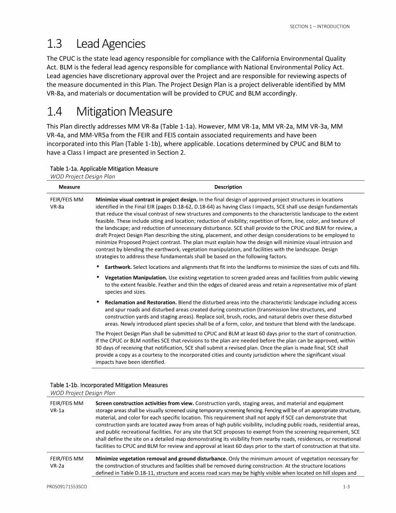
1.4 Mitigation Measure This Plan directly addresses MM VR-8a (Table 1-1a). However, MM VR-1a, MM VR-2a, MM VR-3a, MM VR-4a, and MM-VR5a from the FEIR and FEIS contain associated requirements and have been incorporated into this Plan (Table 1-1b), where applicable. Locations determined by CPUC and BLM to have a Class I impact are presented in Section 2.
Table 1-1a. Applicable Mitigation Measure WOD Project Design Plan
Measure Description
FEIR/FEIS MM VR-8a
Minimize visual contrast in project design. In the final design of approved project structures in locations identified in the Final EIR (pages D.18-62, D.18-64) as having Class I impacts, SCE shall use design fundamentals that reduce the visual contrast of new structures and components to the characteristic landscape to the extent feasible. These include siting and location; reduction of visibility; repetition of form, line, color, and texture of the landscape; and reduction of unnecessary disturbance. SCE shall provide to the CPUC and BLM for review, a draft Project Design Plan describing the siting, placement, and other design considerations to be employed to minimize Proposed Project contrast. The plan must explain how the design will minimize visual intrusion and contrast by blending the earthwork, vegetation manipulation, and facilities with the landscape. Design strategies to address these fundamentals shall be based on the following factors.
Earthwork. Select locations and alignments that fit into the landforms to minimize the sizes of cuts and fills.
Vegetation Manipulation. Use existing vegetation to screen graded areas and facilities from public viewing to the extent feasible. Feather and thin the edges of cleared areas and retain a representative mix of plant species and sizes.
Reclamation and Restoration. Blend the disturbed areas into the characteristic landscape including access and spur roads and disturbed areas created during construction (transmission line structures, and construction yards and staging areas). Replace soil, brush, rocks, and natural debris over these disturbed areas. Newly introduced plant species shall be of a form, color, and texture that blend with the landscape.
The Project Design Plan shall be submitted to CPUC and BLM at least 60 days prior to the start of construction. If the CPUC or BLM notifies SCE that revisions to the plan are needed before the plan can be approved, within 30 days of receiving that notification, SCE shall submit a revised plan. Once the plan is made final, SCE shall provide a copy as a courtesy to the incorporated cities and county jurisdiction where the significant visual impacts have been identified.
Table 1-1b. Incorporated Mitigation Measures WOD Project Design Plan
FEIR/FEIS MM VR-1a
Screen construction activities from view. Construction yards, staging areas, and material and equipment storage areas shall be visually screened using temporary screening fencing. Fencing will be of an appropriate structure, material, and color for each specific location. This requirement shall not apply if SCE can demonstrate that construction yards are located away from areas of high public visibility, including public roads, residential areas, and public recreational facilities. For any site that SCE proposes to exempt from the screening requirement, SCE shall define the site on a detailed map demonstrating its visibility from nearby roads, residences, or recreational facilities to CPUC and BLM for review and approval at least 60 days prior to the start of construction at that site.
FEIR/FEIS MM VR-2a
Minimize vegetation removal and ground disturbance. Only the minimum amount of vegetation necessary for the construction of structures and facilities shall be removed during construction. At the structure locations defined in Table D.18-11, structure and access road scars may be highly visible when located on hill slopes and

SECTION 1 – INTRODUCTION
1-4 PR0509171553SCO
Table 1-1b. Incorporated Mitigation Measures WOD Project Design Plan
along ridges, or when visible from elevated vantage points. In order to reduce visual impacts, the boundaries of all areas to be disturbed at the locations defined in Table D.18-11 shall be delineated consistent with the requirements of Biological Resources Mitigation Measure VEG-1c. Staking shall define staging areas, access roads, spur roads, tower locations, pulling sites, and sites for temporary placement of spoils. Stakes and flagging shall be installed before construction and in consultation with the Project Biologist and the CPUC/BLM Environmental Monitor or Visual Specialist. Areas staked shall be as small as possible in order to minimize the visibility of ground disturbance from sensitive viewing locations such as roads, trails, residences, and recreation facilities and areas. Parking areas and staging and disposal site locations shall be similarly located in areas approved by the Project Biologist and CPUC/BLM’s Environmental Monitor or Visual Specialist prior to the start of construction. All disturbances by Proposed Project vehicles and equipment shall be confined to the staked and flagged areas.
FEIR/FEIS MM VR-3a
Reduce color contrast of retaining walls, land scars, and graveled surfaces. Where construction would unavoidably create land scars or retaining walls visible from sensitive public viewing locations (as defined in Table D.18-11), disturbed soils and new walls shall be treated with an appropriate color or material (Natina Concentrate, Eonite, or Permeon, or similar). The material shall be approved by the CPUC and BLM, and the intent shall be to reduce the visual contrast created by the lighter-colored disturbed soils and rock with the darker soil and vegetated surroundings. SCE shall consult with the CPUC and BLM and/or their authorized representative(s) on a site-by-site basis and obtain written approval prior to the use of any colorants.
FEIR/FEIS MM VR-4a
Minimize in-line views of retaining walls and land scars. In its final Project design, SCE shall incorporate design features that reduce the in-line visibility of all access and spur roads, retaining walls, and ground disturbance areas at the locations defined in Table D.18-11. These design features include alternative access and spur road routes, the use of “drive and crush” access, and redesign and placement of retaining walls to reduce the need for new roads and retaining walls and to reduce or eliminate the in-line visibility of these facilities. SCE’s final design shall document the process used to minimize visibility of the access roads or other visible road features and shall include the following:
• Vegetation that would be affected and steepness of terrain for consideration of vegetation and erosion impacts.
• Areas where “drive and crush” access is a feasible measure to avoid access road scars (i.e., no grading or vegetation removal is required). SCE shall define frequency of driving, vehicle types to be used, and likelihood of vegetation recovery.
This documentation shall be provided to the CPUC/BLM at least 90 days prior to the start of construction.
FEIR/FEIS MM VR-5a
Prohibit construction marking of natural features. SCE shall not apply paint or permanent discoloring agents to rocks or vegetation to indicate survey or construction activity limits or for any other purpose. This measure does not apply to temporary marking agents used to identify underground utilities.
Notes: To avoid redundancy, the FEIR/FEIS MM language was copied from the CPCN (CPUC, 2016a). While subtle differences in MM language were noted upon review of the record of decision (BLM, 2016b), the requirements are the same. References for the citations in the requirement descriptions can be found in the source documents. Source: CPUC, 2016a
1.5 Applicable Project Segments The Plan addresses Project design elements required to be incorporated into final design, as reasonable and feasible, prior to construction and implemented post-construction as part of restoration activities for applicable Project locations (i.e., on Public Lands managed by BLM within the right-of-way or at locations determined to have Class I or Class II impacts not located on Public Lands).
SECTION 1 – INTRODUCTION
PR0509171553SCO 1-5
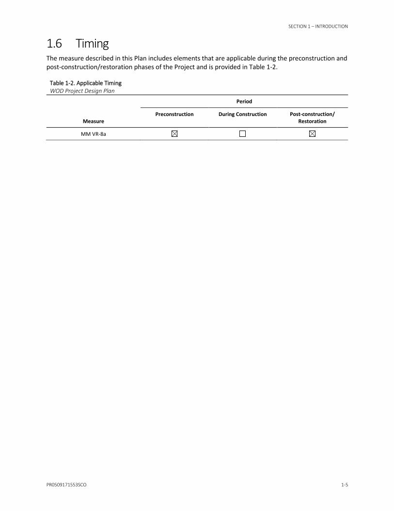
1.6 Timing The measure described in this Plan includes elements that are applicable during the preconstruction and post-construction/restoration phases of the Project and is provided in Table 1-2.
Table 1-2. Applicable Timing WOD Project Design Plan
Measure
Period
Preconstruction During Construction Post-construction/ Restoration
MM VR-8a

SECTION 2
PR0509171553SCO 2-1
Methods This Plan has been developed to describe the design considerations that have been or will be undertaken to reduce the visual contrast of new structures and components by using design fundamentals to blend project elements with the characteristic of the existing landscape.
Potential visual impacts from the Project were determined through FEIR/FEIS analysis. Class I impacts could occur in four general areas:
1. Segment 4 for approximately 16 percent of the residences on the south side of the ROW between Palmer Avenue and Mockingbird Lane.
2. Segment 5 when viewed from residences on North Hathaway Street, North Allen Street, North Evans Street, and North Cherry Street in eastern Banning.
3. Segment 6 when viewed from several residences along the north sides of Amethyst Drive and Haugen-Lehmann Way in the central portion of the community of Whitewater.
4. The Subtransmission Line Route when viewed from the Cottage Lane residential subdivision on Iowa Street and Orange Avenue in the City of Redlands.
Throughout the Project, including at these four general area locations, SCE will use design fundamentals that reduce the visual contrast of new structures and components to the existing landscape, to the extent feasible.
2.1.1 Design Considerations During preliminary design and prior to detailed development of final engineering drawings, the existing terrain was evaluated relative to the siting and placement of structures, access roads, staging areas, and associated project features. The intent of the evaluation was to meet the requirements of the Project while minimizing the visual contrast of project design.
As part of the evaluation, SCE considered the following:
• The technical requirements of a project feature.
• The potential sites and/or alignments available for a feature within the existing or proposed right-of-way.
• Existing conditions, including access, water features, topography/terrain, vegetation, hazards, location of sensitive receptors, and other potential opportunities and constraints associated with a Project feature or element.
• The technical requirements of associated features and elements (e.g., adjacent structures, conductor swing, ground clearance, access, staging areas).
SCE used or will use the following design considerations (are required by MM VR-8a), as feasible and practicable, to minimize visual contrast in project design:
• Siting and location:
− Project structures were spaced within the right-of-way to provide for groupings of new and existing adjacent structures to visually simplify the presence of new and existing adjacent structures within the utility corridor.
− Project structures and other features were located away from occupied buildings to maximize the distance from sensitive receptors.

SECTION 2 – METHODS
2-2 PR0509171553SCO
− Project was located within existing right-of-way to minimize acquisition of additional right-of-way.
• Reduction of visibility:
− Placement of structures on hill and mountain ridgelines was minimized, and structures were located on side slopes when practicable.
− Existing access was used where possible, and new access was placed to minimize visibility (e.g., designed to follow slope around hills and avoid going straight uphill over ridge tops)
− Construction yards, staging areas, and material and equipment storage areas will be visually screened using temporary screening fencing consistent with VR-1a.
− SCE minimized in-line views of retaining walls and land scars consistent with VR-4a.
− SCE will prohibit construction marking of natural features consistent with VR-5a.
− Existing vegetation will be left in place to screen graded areas and facilities from public viewing to the extent feasible. Edges of cleared areas will be feathered and thinned to retain a representative mix of plant species and sizes.
• Repetition of form, line, color, and texture of the landscape:
− SCE will reduce color contrast of retaining walls, land scars, and graveled surfaces consistent with VR-3A and discussed in detail in the Surface Treatment Plan.
− SCE will blend the disturbed areas into the characteristic landscape, including access and spur roads and disturbed areas created during construction (transmission line structures, and construction yards and staging areas). SCE will also replace soil, brush, rocks, and natural debris over these disturbed areas. Additionally, SCE will select introduced plant species of a form, color, and texture that blend with the landscape as described in detail in the Habitat Restoration and Revegetation Plan (HRRP).
• Reduction of unnecessary disturbance:
− Vegetation removal and ground disturbance will be minimized consistent with VR-2a.
− Locations and alignments were selected that fit into the landforms to minimize the sizes of cuts and fills, as feasible.
− Existing elements (e.g., access) and disturbed areas will be used to the extent possible for project requirements (e.g., for staging areas).
SCE will provide the final design that documents how SCE integrated the results of the evaluation and design considerations. SCE will construct the project in a manner that best meets the project technical requirements within the existing or proposed right-of-way in a manner consistent, as feasible, with MM VR-8a.
2.1.2 Coordination with Local Governments Upon finalization of this Plan, SCE will provide a copy as a courtesy to the incorporated cities and county jurisdictions where the significant visual impacts have been identified.

SECTION 3
PR0509171553SCO 3-1
Plan Approval This Plan has been prepared to address the requirements of MM VR-8a. SCE requests review and approval of this Plan from the CPUC and BLM. Upon finalization of this Plan, SCE will provide a copy as a courtesy to the incorporated cities and county jurisdictions where the significant visual impacts have been identified.

SECTION 4
PR0509171553SCO 4-1
References Bureau of Land Management (BLM). 2016a. Final Environmental Impact Statement. West of Devers Upgrade Project. Available online at http://www.blm.gov/ca/st/en/fo/palmsprings/transmission/ WestOfDeversProject.html.
Bureau of Land Management (BLM). 2016b. Record of Decision for the West of Devers Upgrade Project. BLM/CA/PL-2015/012+1793, DOI-BLM-CA-060-0015-0021, CACA-055285. December.
California Public Utilities Commission (CPUC). 2015. Final Environmental Impact Report (FEIR) Southern California Edison’s West of Devers Upgrade Project. SCH #2014051041. December.
California Public Utilities Commission (CPUC). 2016a. Addendum to Final Environmental Impact Report Southern California Edison’s West of Devers Upgrade Project. SCH #2014051041. April.
California Public Utilities Commission (CPUC). 2016b. Decision Granting Certificate of Public Convenience and Necessity for the West of Devers Upgrade Project and Related Matter. August. Available online at http://docs.cpuc.ca.gov/PublishedDocs/Published/G000/M166/K441/166441910.pdf.
SECTION 5
PR0509171553SCO 5-1
Revisions Revisions made to standard text (black ink) should be noted below to document changes in requirements or SCE’s approach to this Project Design Plan.
Date Description of Revision Contact

Figure

Source: SCE, Bing Maps
H:\cheron\proj\SoCalEDISON\668030WOD\09-MitigationPlans\ProjectDesignPlan\04-Figure\Fig1_WOD_TransLineRoute.pdf
FIGURE 1-1
Southern California EdisonWest of Devers Upgrade Project
Project Location Map0 1.5 3
Miles Sheet IndexMap Extent
LEGENDProject Study AreaExisting Transmission Line Right of WayProposed Right of Way
") Substation
Segment 1Segment 2Segment 3Segment 4Segment 5Segment 6
U.S. Bureau of Land ManagementMorongo ReservationWestern Riverside County MSHCPCoachella Valley MSHCPCity Boundary
SCE Service Territory