PROJECT DESCRIPTION UPDATE NORTH-SOUTH PROJECT
66
PROJECT DESCRIPTION UPDATE NORTH-SOUTH PROJECT July 31, 2015
Transcript of PROJECT DESCRIPTION UPDATE NORTH-SOUTH PROJECT

PROJECT DESCRIPTION UPDATE
NORTH-SOUTH PROJECT
July 31, 2015

Project Description of the North-South
A-1 July 2015
TABLE OF CONTENTS
1.1 Background ......................................................................................................................... 3
1.2 Project Description ............................................................................................................. 3
2 PROJECT PURPOSE, NEED, AND OBJECTIVES ................................................................. 4
2.1 Purpose and Need............................................................................................................... 4
2.2 Project Objectives ............................................................................................................... 5
3 PROJECT DESCRIPTION .......................................................................................................... 6
3.1 Project Location and Description of Existing Facilities ....................................................... 6
3.2 Existing System ................................................................................................................. 10
3.3 Project Objectives ............................................................................................................. 14
3.4 Overview of Proposed Project .......................................................................................... 14
3.5 Proposed Project Components ......................................................................................... 15
3.6 Facility Route Selection and Evaluation Process ............................................................... 21
3.7 Right-of-Way Requirements ............................................................................................. 22
3.8 Construction...................................................................................................................... 23
3.9 Post-Construction Project Operations ................................................................................ 8
3.10 Applicant Proposed Measures .......................................................................................... 14
TABLES
Table 3-3 Pipeline Segment Descriptions ................................................................................................... 17
Table 3-4 Equipment Requirements for Compressor Station Construction ............................................... 27
Table 3-9 Equipment Requirements for Pipeline Construction (per Spread) ............................................... 1
Table 3-10 Equipment Requirements for Each HDD ..................................................................................... 2
Table 3-11 Proposed Construction Timeline ................................................................................................. 4
Table 3-12 Typical Labor Requirements for Compressor Station Construction ........................................... 6

Project Description of the North-South
A-2 July 2015
Table 3-13 Typical Labor Requirements for Pipeline Construction (per Spread) ......................................... 7
Table 3-14 Typical Labor Requirements for Directional Drilling (per Spread) .............................................. 7
Table 3-15 Covered Activities ....................................................................................................................... 1
Table 3-17 Applicant Proposed Measures .................................................................................................. 14
Project Description of the North-South
A-3 July 2015
1.1 Background
SoCalGas and SDG&E are proposing to construct the North–South Project (Proposed Project) to maintain reliability and alleviate the potential for curtailments of customers served by a portion of the Applicant’s transmission system known as the “Southern System” due to a potential discrepancy between customer demand and the volume of flowing supplies delivered to the Southern System to meet that demand. Unlike other parts of SoCalGas’ system, the Southern System requires minimum flow volumes at the Blythe and/or Otay Mesa receipt points to maintain service to its customers in the Imperial Valley and San Diego load centers and other communities in San Bernardino and Riverside Counties. The Proposed Project would create a pipeline interconnection allowing the Applicant to efficiently transport 800 million cubic feet per day (MMcfd) of natural gas supplies into the Southern System from interstate and intrastate receipt points located outside of the Southern System. These additional receipt points include North Needles, South Needles, Kramer Junction, Wheeler Ridge, and Kern River Station (as shown on Figure 1-1) and storage supplies from the SoCalGas Honor Rancho natural gas storage facility.
1.2 Project Description
The primary components of the Proposed Project include the construction a 36-inch-diameter transmission pipeline comprised of the Adelanto to Moreno pipeline and the rebuilding of the Adelanto Compressor Station. Total pipeline length for the Adelanto to Moreno pipeline would be approximately 65 miles. The pipeline would be primarily constructed within existing public and private rights-of-way (for a depiction of the pipeline alignment, see Figure 1-2). The Adelanto to Moreno pipeline would be approximately 65 miles in length and would begin at the Adelanto Compressor Station in the high desert city of Adelanto and would proceed in a southerly direction through the Cajon Pass and the San Bernardino National Forest, terminating at the Moreno Pressure Limiting Station in the City of Moreno Valley. The Adelanto Compressor Station would be rebuilt with approximately 30,000 horsepower (HP) of compression in order to accommodate the design throughput. Additional Proposed Project components include: (i) installation of additional pressure limiting equipment at Moreno Pressure Limiting Station and Whitewater Pressure Limiting Station and (ii) installing pressure limiting equipment at the proposed Shaver Summit Pressure Limiting Station near the City of Indio and at the Desert Center Compressor Station near the community of Desert Center.
The Applicant anticipates that the Proposed Project would include construction activities within the following cities and counties: Adelanto, Victorville, Highland, San Bernardino, Colton, Loma Linda, Moreno Valley, , San Bernardino County and Riverside County. Construction would also occur on lands subject to U.S. Forest Service (USFS) jurisdiction. The Applicant anticipates that environmental review for the Proposed Project would include the preparation of an environmental impact report / environmental impact statement (EIR/EIS) in accordance with the California Environmental Quality Act (CEQA) and NEPA.
Project Description of the North-South
A-4 July 2015
2 PROJECT PURPOSE, NEED, AND OBJECTIVES
2.1 Purpose and Need
As natural gas utility providers regulated by the CPUC, SoCalGas and SDG&E have an obligation to provide safe and reliable natural gas service to all natural gas customers in their service territory. SoCalGas and SDG&E own and operate an integrated gas transmission system consisting primarily of pipelines, compressor stations, storage facilities and other appurtenant facilities. With a network of transmission pipelines, compressor stations, and four interconnected storage fields, SoCalGas and SDG&E deliver natural gas to over twenty million residential and business customers.
The service provided by the Applicant includes providing comprehensive transportation and natural gas procurement service for residential, small commercial and industrial customers, and transportation-only service for large customers, such as large electric generators. These large customers procure their own natural gas, which primarily comes from producing areas in the Southwest and Rocky Mountain states (see Figure 2-1). Transportation service for the out-of-state natural gas to load areas within Southern California is provided by SoCalGas and SDG&E. These large customers can have their purchased natural gas delivered to any receipt point within the Applicant’s system (see Figure 1-1). This customer-friendly arrangement is made possible by the interconnected design of SoCalGas and SDG&E’s pipelines and SoCalGas’ substantial storage assets. These physical assets enable Applicant to receive gas at one location and deliver like volumes to a location hundreds of miles away, notwithstanding physical flows that may prevent gas supplies from actually being exchanged between these two particular points.
One portion of SoCalGas’ and SDG&E’s interconnected transmission system—SoCalGas’ Southern Transmission System (Southern System)—requires minimum flowing supplies of natural gas from receipt points in the Southern System each day. This is because the Southern System can currently only receive a relatively small amount of flowing supplies from other parts of the SoCalGas and SDG&E system, and no supplies from storage. Without these minimum supplies, reliability is compromised if there is not enough natural gas supply in the Southern System to provide all customers with their load requirements. Load demand on the Southern System may increase, and available supplies at the receipt points may decrease. Consequently, customers on the Southern System may face supply-based curtailments on a regular basis. “Curtailments” often cause a shutdown of customer operations when natural gas becomes unavailable, resulting in lost customer production, financial losses, potential loss of jobs, and for large electric generator customers, can lead to electrical blackouts. This situation creates unique and challenging operational and reliability issues for the Southern System.
Most of the flowing supplies that arrive at Southern System receipt points are sourced from one pipeline: El Paso Natural Gas Company’s El Paso South Mainline (El Paso). Southern System customers have faced reliability problems in the past because of this situation, including a Southern System curtailment in

Project Description of the North-South
A-5 July 2015
February of 2011 brought about by force majeure conditions upstream of the SoCalGas system, several recent supply-related near misses, and operational issues that have created reliability concerns.
These reliability concerns have been heightened by the closure of the San Onofre Nuclear Generating Station (SONGS). Since the SONGS outage began in early 2012, SoCalGas and SDG&E have seen increased demand on the Southern System by electric generators of 80–100 MMcfd. There are additional gas-fired generation projects proposed within SoCalGas and SDG&E service territories. Although some of the available 2,150 megawatts of lost SONGS power will be met by out-of-state generation, expected increases in overall electric generation demand indicate that Southern System demand will not decline below 2012/2013 levels (CPUC et al. 2013; CEC 2013).1 In addition, exports from the United States to Mexico are likely to substantially increase within the next decade and many of these exports would be delivered over the El Paso South Mainline. As deliveries to Mexico from the El Paso system increase, supplies into Blythe would become more scarce and expensive. This decrease in available supplies at Blythe would make it more difficult to find supplies when problems occur in the supply basins or on interstate pipelines serving Southern California.
2.2 Project Objectives
SoCalGas and SDG&E have identified the following Project Objectives for meeting the North–South Project purpose and need:
• Provide safe and reliable gas service, in a timely and cost effective manner to Southern System customers.
• Maintain Southern System reliability and alleviate the potential for curtailments of customers on the Southern System due to the discrepancy between customer demand and the volume of flowing supplies delivered to the Southern System to meet that demand.
• Resolve supply-related risks to the Southern System by providing Southern System customers with access to storage supplies and more receipt points located outside of the Southern System (Topock, Needles, Wheeler Ridge, Kern River Station, and Kramer Station).
• Provide an interconnection allowing the Applicant to efficiently transport 800 MMcfd of natural gas supplies into the Southern System from interstate and intrastate receipt points located outside of the Southern System.
1 Estimates for incremental electric generation need in 2020 are as high as 920 megawatts in SDG&E’s service territory and 4,600 megawatts in Southern California Edison’s service territory, including repowered plans and renewables (CEC 2013).
Project Description of the North-South
A-6 July 2015
• Provide Southern System natural gas customers (including electric generators) located on the Southern System with the same level of reliability that customers receive elsewhere on SoCalGas and SDG&E’s integrated transmission system.
• Complete the Proposed Project as soon as possible to mitigate the risk of curtailments caused by (i) increased demand in the Southern System caused by the decommissioning of SONGS and (ii) future projects that are expected to decrease available supplies at the Southern System receipt point.
3 PROJECT DESCRIPTION
The following sections describe the primary components of the Proposed Project, which include infrastructure modifications at the Adelanto Compressor Station and construction of a new approximately 65-mile natural gas pipeline. This chapter also describes the Proposed Project location, anticipated construction methodology, route selection and evaluation process, right-of-way requirements, and operations and maintenance requirements associated with the Proposed Project. In addition, Applicant Proposed Measures (APMs) are listed in this section.
3.1 Project Location and Description of Existing Facilities
The section below provides an overview of the location of the Proposed Project, a description of key locations, and a summary of the existing SoCalGas facilities that would be affected by the Proposed Project.
3.1.1 Project Location
As shown in Figure 1-2, the Proposed Project originates in the southern portion of the Mojave Desert and extends for 65 miles to the south through the Cajon Pass (a mountain pass between the San Gabriel and San Bernardino Mountain Ranges), and across the San Bernardino Valley. The pipeline passes through a number of jurisdictions along its route, which are listed in Table 3-1. The pipeline alignment would be located within existing SoCalGas right-of-way, other existing utility corridors, public right-of-way (i.e., public roads), and new SoCalGas right-of-way.
Certain key locations related to existing facilities that would be affected by the Proposed Project are noted below.
• Adelanto Compressor Station: An approximately 3.2-acre site located generally 0.1 miles east of the intersection of Koala Road and Rancho Road in the City of Adelanto.
• Moreno Pressure Limiting Station: An approximately 1-acre site located generally 1,500 feet south of the intersection of Virginia Street and Alessandro Street in the City of Moreno Valley.
Project Description of the North-South
A-7 July 2015
• Whitewater Pressure Limiting Station: An approximately 0.5-acre site located generally 2,000 feet south of Interstate 10 (I-10) and generally 1,500 feet west of Kellogg Road in the County of San Bernardino.
• Desert Center Compressor Station: An approximately 4-acre site located generally 300 feet south of I-10 and generally 1 mile east of the community of Desert Center at Desert Center Rice Road in the County of San Bernardino.
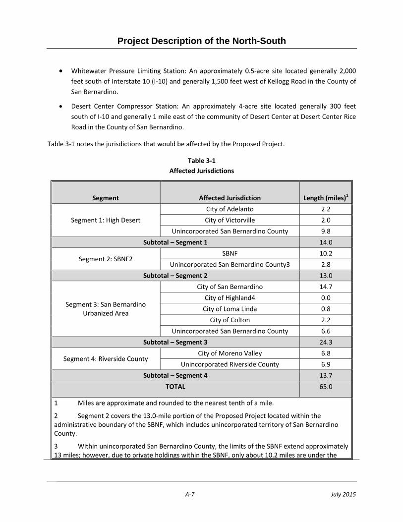
Table 3-1 notes the jurisdictions that would be affected by the Proposed Project.
Table 3-1 Affected Jurisdictions
Segment Affected Jurisdiction Length (miles)1
Segment 1: High Desert City of Adelanto 2.2 City of Victorville 2.0
Unincorporated San Bernardino County 9.8 Subtotal – Segment 1 14.0
Segment 2: SBNF2 SBNF 10.2
Unincorporated San Bernardino County3 2.8 Subtotal – Segment 2 13.0
Segment 3: San Bernardino Urbanized Area
City of San Bernardino 14.7 City of Highland4 0.0
City of Loma Linda 0.8 City of Colton 2.2
Unincorporated San Bernardino County 6.6 Subtotal – Segment 3 24.3
Segment 4: Riverside County City of Moreno Valley 6.8
Unincorporated Riverside County 6.9 Subtotal – Segment 4 13.7
TOTAL 65.0
1 Miles are approximate and rounded to the nearest tenth of a mile.
2 Segment 2 covers the 13.0-mile portion of the Proposed Project located within the administrative boundary of the SBNF, which includes unincorporated territory of San Bernardino County.
3 Within unincorporated San Bernardino County, the limits of the SBNF extend approximately 13 miles; however, due to private holdings within the SBNF, only about 10.2 miles are under the

Project Description of the North-South
A-8 July 2015
jurisdiction of the U.S. Forest Service.
4 The Proposed Project is within the city of Highland for approximately 0.04 mile, which, when rounded to the nearest tenth of a mile, is less than 0.1 mile.
3.1.2 Description of Existing Facilities
This section describes the existing facilities that would be affected by the Proposed Project.
Adelanto Compressor Station
The Adelanto Compressor Station contains a single natural gas turbine-driven compressor that was installed in the early 1970s. There are five pipelines that intersect at the Adelanto Compressor Station; the compressor can compress gas supply west toward the City of Palmdale or south toward the Cajon Pass. Valves can be operated to control flows of natural gas into particular pipelines. Supporting equipment includes:
• Filter separator: cleans the natural gas that enters the turbine and compressor by removing particulate matter and liquid to prevent equipment damage.
• Natural gas coolers: cool the compressed natural gas to a specific temperature range prior to entering the pipeline.
• Compressor oil coolers: cool oil to manufacturer’s specifications prior to re-entering the gas compressor.
• Control room: contains electric switch gear, supervisory control and data acquisition (SCADA) equipment and local control panels for operating the turbine and monitoring station.
• Natural gas generator (845 HP): provides electricity to the turbine. The generator is housed in a non-combustible building with water cooling equipment and lubricating oil cooling outside the building.
• Emergency blowdown stack and oil separator: safety equipment that allow for rapid depressurization of station piping.
• Electric air compressor (10 HP): provides air for utilities.
• Restroom building: provides restroom facilities, which are connected to the public sewer system.
• Vessels and drums storage areas: contain unused and used oil stored in vessels or drums in two primary storage areas, one for the compressor and one for the generator. Each storage area sits on a concrete pad surrounded by concrete walls for spill containment.
• Water storage tank: provides 12,000 gallons of storage capacity for fire suppression equipment.

Project Description of the North-South
A-9 July 2015
• In-line inspection launchers/receivers: enable internal inspection of three of the four pipelines. There are two in-line inspection tool launchers and one in-line inspection tool receiver.
• Pressure limiting station: regulates natural gas pressure entering the station from a pipeline with higher Maximum Allowable Operating Pressure (MAOP).
• Cathodic protection system: protects the station piping from corrosion.
Moreno Pressure Limiting Station
The Moreno Pressure Limiting Station consists of existing above- and below-grade piping, valves, blowdown facilities, pressure limiting equipment, concrete supports, concrete pads and perimeter fencing. Three pipelines enter the station and connect to existing station piping, valves, and pressure limiting equipment. Pressure limiting equipment regulates natural gas pressure entering the station from three pipelines with higher MAOP to two pipelines with lower MAOP. Those two pipelines exit the station to the west towards Los Angeles, while three pipelines exit the station to the south toward San Diego without pressure regulation. There is currently one in-line inspection tool launcher and one in-line inspection tool receiver to enable in-line inspection of two pipelines. This station has one small enclosure for communications equipment, commercial power and a radio antenna.
White Water Pressure Limiting Station
The White Water Pressure Limiting Station consists of existing above- and below-grade piping, valves, blowdown facilities, pressure limiting equipment, concrete supports, concrete pads and perimeter fencing. Three pipelines enter the station from the east and interconnect with existing station piping, valves and pressure limiting equipment. Pressure limiting equipment regulates natural gas pressure entering the station from pipelines with higher MAOPs to three pipelines with lower MAOPs; these three pipelines then exit the station to the west. There is currently one in-line inspection tool launcher and one in-line inspection tool receiver to enable in-line inspection of one pipeline. This station has one small enclosure for communications equipment, solar power equipment and radio antenna.
Desert Center Compressor Station
The Desert Center Compressor Station consists of an existing compressor building, natural gas coolers, control building, above- and below-grade piping, valves, blowdown facilities, concrete supports, concrete pads and perimeter fencing. Three pipelines enter the station from the east and interconnect with valves. Over-pressure protection equipment protects the connected pipelines. Three pipelines exit the station to the west.
Project Description of the North-South
A-10 July 2015
3.2 Existing System
A map of the SoCalGas transmission system is shown on Figure 1-1. The transmission system extends from the Colorado River on the eastern end of SoCalGas’ approximately 20,000-square-mile service territory to the Pacific Coast on the western end and from Tulare County in the north to the U.S./Mexico border in the south (excluding parts of Orange County and San Diego County).
The SoCalGas transmission system was initially designed to receive and deliver gas from the east to the load centers in the Los Angeles basin, Imperial Valley, San Joaquin Valley, north coastal areas, and San Diego County. As SoCalGas and SDG&E’s customers sought to access new supply sources in Canada and the Rocky Mountain region, the system was modified to concurrently accept deliveries from the north. As a result, the system can now accept up to 3,875 MMcfd of interstate and local California supplies on a firm basis.
As illustrated in Figure 2-1, primary supply sources are the southwestern United States, the Rocky Mountain region, and California on- and off-shore production. Other supply sources include basins in Canada. The interstate pipelines that supply the SoCalGas transmission system are El Paso Natural Gas Company (El Paso), North Baja Pipeline (North Baja), Transwestern Pipeline Company (Transwestern), Kern River Gas Transmission Company (Kern River), Mojave Pipeline Company (Mojave), Questar Southern Trails Pipeline Company (Southern Trails), and Gas Transmission Northwest (GTN) via the intrastate system of Pacific Gas and Electric Company (PG&E). The SoCalGas transmission system interconnects with El Paso at the Colorado River near Needles and Blythe, with North Baja near Blythe, and with Transwestern and Southern Trails near Needles. SoCalGas also interconnects with the common Kern/Mojave pipeline at Wheeler Ridge in the San Joaquin Valley and at Kramer Junction in the high desert. At Kern River Station in the San Joaquin Valley, SoCalGas maintains a major interconnection point with the PG&E intrastate pipeline system and receives PG&E/GTN deliveries at that location.
SoCalGas also operates four storage fields that interconnect with its transmission system. These storage fields—Aliso Canyon, Honor Rancho, La Goleta, and Playa del Rey—are located near the primary load centers of the SoCalGas system. Together they have a combined inventory capacity of 137.1 billion cubic feet, a combined firm injection capacity of 850 MMcfd, and a combined firm withdrawal capacity of 3,195 MMcfd. Upon completion of the Aliso Canyon Turbine Replacement Project authorized under CPUC Decision D. 13-11-023, the combined firm injection capacity will be 995 MMcfd.
The SDG&E gas transmission system consists primarily of two high-pressure, large-diameter pipelines that extend south from Rainbow Meter Station, located at the Riverside/San Diego County border. Both pipelines terminate at the San Diego metropolitan area. The pipelines are interconnected approximately at their midpoint and again near their southern terminus. The northern cross-tie runs between Carlsbad and Escondido, with the southern cross-tie running through Miramar. A large diameter pipeline also extends from the cross-tie at Miramar to Santee. At Santee, another large diameter pipeline extends to the Otay
Project Description of the North-South
A-11 July 2015
Mesa metering station at the U.S./Mexico border. At Otay Mesa, the SDG&E system interconnects with the Transportadora de Gas Natural de Baja, California, S.de R.L. de C.V. (TGN) pipeline, providing another receipt point for supplies into the SoCalGas/SDG&E system. A small-diameter, lower-pressure pipeline owned by SoCalGas also extends south from Orange County down to San Diego. SDG&E’s Moreno Compressor Station, located in Moreno Valley, boosts pressure into the SoCalGas transmission lines serving Rainbow Meter Station. SDG&E has no storage fields in its service territory.
Southern System
The SoCalGas Southern System is a subset of the Applicant’s entire natural gas transmission system, and consists primarily of three high-pressure pipelines extending west from the Colorado River near Blythe to the Moreno Pressure Limiting Station in the City of Moreno Valley. Five pipelines exit the Moreno Pressure Limiting Station. Two high-pressure pipelines exit the Moreno Pressure Limiting Station and extend west into the Los Angeles Basin. Three high-pressure pipelines extend south from the Moreno Pressure Limiting Station to the SDG&E gas transmission system.
The Southern System was primarily designed to receive gas from the El Paso pipeline at the Colorado River near Blythe and to deliver it to load centers in the Inland Empire, Imperial Valley, San Diego and the Los Angeles Basin. The pipelines’ operating pressures are higher at the Blythe receipt point and lower near the load centers. The Southern System can receive limited supplies from other pipelines within the SoCalGas transmission system through the use of two valve stations, Chino Station and Prado Station, which are located along the two high-pressure pipelines extending west from Moreno Pressure Limiting Station.
Since 2008, supplies can also be received into the Southern System at the Otay Mesa receipt point in San Diego County. However, the volume of supplies received at Otay Mesa has generally been minimal due to the cost of transportation from North Baja to Otay Mesa.
SoCalGas also has the ability to transport up to 80 MMcfd of supply from its Northern System to the Southern System via Transmission Line 6916.
Southern System Minimum Flow Requirements
Unlike other portions of the combined SoCalGas/SDG&E transmission system, the Southern System requires minimum flows at the Blythe or Otay Mesa receipt points to maintain service to customers in the Imperial Valley and San Diego load centers and to customers and communities in San Bernardino and Riverside Counties. While supplies from the Chino and Prado Stations can flow eastward, these

Project Description of the North-South
A-12 July 2015
stations cannot meet the demand of the Southern System.2 As a result, additional supply must be delivered at the Blythe or Otay Mesa receipt points to maintain service to customers on the Southern System and to maintain system integrity.
The minimum flow requirements on the Southern System vary with the demand on the system. As demand increases, the minimum flow requirements increase, and vice versa.
Responsibility for Maintaining Southern System Minimum Flow Requirements
In D.07-12-019 the CPUC approved, in part, proposals by SoCalGas, SDG&E, and Southern California Edison Company (SCE) to implement a range of provisions pertaining to the natural gas operations and service offerings of SoCalGas and SDG&E, which were related to core operations, unbundled storage, and expansion of storage capacities. One of the provisions adopted by D.07-12-019 was the transfer of the responsibility for managing minimum flow requirements for system reliability from SoCalGas’ Gas Acquisition Department to the System Operator.3 SoCalGas’ Gas Acquisition Department had previously provided flowing supplies using core customer assets. When the Gas Acquisition department needed to purchase additional spot supplies to meet minimum flow requirements at Blythe beyond 355 MMcfd, its incremental costs to do so were recorded in a memorandum account. The allocation of the costs in that memorandum account was determined in the SoCalGas Biennial Cost Allocation Proceeding (BCAP).
In response to the SoCalGas/SDG&E/SCE Application to transfer this responsibility from the Gas Acquisition Department, D.07-12-019 directed the System Operator to take over the responsibility for managing these minimum flows as of April 1, 2009.
2 Due to the telescoping operating pressures of the pipelines, higher operating pressures of the pipelines east of Moreno Station restrict further eastward flow. In other words, supplies delivered from Chino and Prado Stations generally arrive at Moreno Station at pressures lower than the operating pressures east of Moreno Station.
3 D.07-12-019 mimeo, at 116 (Ordering Paragraph No. 15). Although the decision refers to “Gas Acquisition Department,” tariffs filed in that proceeding and later proceedings use the phrase “Utility Gas Procurement Department.” Both terms refer to the same group. Note that the System Operator is broadly defined to constitute the SoCalGas departments responsible for the operation of its transmission system, including storage, hub services, pooling services receipt point access, off-system deliveries, and system reliability. It does not include Gas Acquisition. See D.07-12-019, mimeo., at 58. See also SoCalGas Rule 41(2).
Project Description of the North-South
A-13 July 2015
Past and Current Efforts by SoCalGas to Maintain Southern System Minimum Flow Requirements
In D.07-12-019, the CPUC also adopted the request by SoCalGas, SDG&E, and SCE for System Operator tools for maintaining system reliability.4 These tools are as follows:
a The ability of the System Operator to buy and sell gas on a spot basis, as needed, to maintain system reliability.
b Authority to conduct requests for offers (RFO) or open season process consistent with the System Operator needs.
c Authority to approve an expedited Advice Letter approval process for contracts that result from an RFO or open season process.5
The System Operator regularly uses its ability to buy and sell spot gas to maintain minimum flows on the Southern System. These purchases and sales are discussed in detail in annual advice filings by SoCalGas.
The System Operator has used the RFO process to enter into baseload contracts for Southern System support, and SoCalGas has sought and obtained authorization for additional System Operator tools to help maintain Southern System minimum flows, including the ability to move supply from Blythe, California, to Otay Mesa, California,6 and a series of CPUC authorized Memorandums in Lieu of Contract (MILCs) between the System Operator and the Gas Acquisition Department. Under these MILCs, the bundled core agrees to deliver a share of the Southern System minimum flow requirement, and in return is relieved from Southern System support costs incurred by the SoCalGas System Operator. SoCalGas has discounted Backbone Transportation Service (BTS) to encourage shippers to bring gas into the Southern System.
In late 2012, SoCalGas put a pipeline into service, Line 6916, that enables additional supplies delivered at South Needles to reach the Southern System, providing another source of supply to the Southern System.
4 D.07-12-019, mimeo., at 67 and 112 (Ordering Paragraph No. 16).
5 D.07-12-019, mimeo., at 112 (Ordering Paragraph No. 16).
6 See Resolution G-3474.
Project Description of the North-South
A-14 July 2015
3.3 Project Objectives
As described in Section 2.2, the Applicant has identified the following Project Objectives for the Proposed Project:
• Provide safe and reliable gas service, in a timely and cost effective manner to Southern System customers.
• Maintain Southern System reliability and alleviate the potential for curtailments of customers on the Southern System due to the discrepancy between customer demand and the volume of flowing supplies delivered to the Southern System to meet that demand.
• Resolve supply-related risks to the Southern System by providing Southern System customers with access to storage supplies and more receipt points located outside of the Southern System (Topock, Needles, Wheeler Ridge, Kern River Station, and Kramer Station).
• Provide an interconnection allowing the Applicant to efficiently transport 800 MMcfd of natural gas supplies into the Southern System from interstate and intrastate receipt points located outside of the Southern System.
• Provide Southern System natural gas customers (including electric generators) located on the Southern System with the same level of reliability that customers receive elsewhere on SoCalGas and SDG&E’s integrated transmission system.
• Complete the Proposed Project as soon as possible to mitigate the risk of curtailments caused by (i) increased demand in the Southern System caused by the decommissioning of SONGS and (ii) future projects that are expected to decrease available supplies at the Southern System receipt point.
3.4 Overview of Proposed Project
As further described below, the Proposed Project consists of the following main components:
• Replacement of existing infrastructure and installation of new infrastructure at the Adelanto Compressor Station, including the natural gas turbine and compressors, exhaust emission treatment equipment, gas and oil cooling equipment, filter separator, auxiliary buildings, blowdown stack, lubrication oil tanks (for unused and used oil), cathodic protection system, and generators
• Installation of approximately 30,000 HP of natural gas compression, new emission control equipment, and in-line inspection tool launcher at the Adelanto Compressor Station
• Construction of the approximately 65-mile-long Adelanto to Moreno pipeline, segmented as follows:

Project Description of the North-South
A-15 July 2015
o Segment 1 – Adelanto Compressor Station to the San Bernardino National Forest Boundary
o Segment 2 – San Bernardino National Forest
o Segment 3 – Swarthout Canyon Road along U.S. Route 66 to Reche Canyon Road
o Segment 4 – Reche Canyon Road to Moreno Pressure Limiting Station
• Station piping modifications and installation of additional pressure limiting and communications equipment at the Moreno Pressure Limiting Station
• Station piping modifications and installation of additional pressure limiting and communications equipment at Whitewater Pressure Limiting Station
• Installation of pressure limiting and communications equipment at the proposed Shaver Summit Pressure Limiting Station
• Modification of existing station piping and installation of pressure limiting and communications equipment at Desert Center Compressor Station
• Installation of sixteen main line block valves.
An overview of the Proposed Project within the Southern System is shown on Figure 1-1. Each of the primary Proposed Project components listed above is also depicted on Figure 3-1.
3.5 Proposed Project Components
The following section describes the components of the Proposed Project.
3.5.1 Adelanto Compressor Station Infrastructure Replacement
The Proposed Project would require approximately 30,000 HP of compression to be provided by three new natural gas-fueled compressors. Combined, the new compressor units would be capable of delivering 800 MMscfd of natural gas at 850 pounds per square inch gauge (psig). The compressor station operating range would vary from 75 MMscfd to 800 MMscfd, with a minimum station suction pressure of 475 psig and a maximum station discharge pressure of 850 psig. The design for the compressor station would provide full performance at all expected operating conditions up to 110°F. An overall station layout is depicted in Figure 3-2.
A selective catalytic reduction emission system would be installed on the exhaust of the gas turbines to comply with Mojave Desert Air Quality Management District (MDAQMD) emissions requirements. An ammonia tank would be installed on a concrete pad surrounded by concrete walls for spill containment. Ammonia would support the selective catalytic reduction system.

Project Description of the North-South
A-16 July 2015
The compressor station would be equipped with an emergency shut-down system. The emergency shut-down system would consist of an air compressor and conditioning vessels for compressed air, automatic series valves and manual trip valves. The isolation time for main line valves will be approximately 30 seconds to 2 minutes to close after closure is initiated. Sensors in the compressor building and elsewhere in the Adelanto Compressor Station can automatically trip the emergency shut-down system, as can the manual trip valves. In an emergency, the emergency shut-down system would automatically activate and close valves that supply natural gas to the turbine and compressors, open bypass valves around the station to allow natural gas to flow through the pipeline system (bypassing the natural gas turbines and compressors), and open blowdown valves that would allow rapid depressurization of the station through a blowdown stack.
Three new natural gas-fueled generators would be installed to provide electricity for the station while the gas turbines are operating. When not operating, electricity would be provided by Southern California Edison, the local power provider. No major electrical infrastructure improvements would be required and upgrades would be limited to on-site electrical facilities.
Equipment for supporting the gas turbines at the modified station would be similar to that of the existing station, as described in Section 3.1. In general, the new equipment would be installed to the south of the existing equipment. A new 20-foot wide access driveway would also be installed to provide vehicular access to equipment, buildings and storage areas. New light fixtures may be required to facilitate occasional (and/or emergency) nighttime operation and maintenance needs within the existing property boundary.
Buildings
Five new buildings, described below, are proposed as part of the Adelanto Compressor Station infrastructure replacement. Buildings would be constructed of non-combustible material (i.e., non-reflective steel, concrete masonry) and would meet applicable building code requirements.
Compressor Building
The compressor building would house the natural gas turbine-driven compressors. The building would be approximately 75 feet wide, 208 feet long, and 35 feet high at the eaves.
Auxiliary Building
The auxiliary building would house the control room, master control center, electric switch gear, an instrumentation parts room, workshop and an equipment room. It would be approximately 40 feet wide, 80 feet long, and 16 feet high.
Generator Building
Project Description of the North-South
A-17 July 2015
A generator building would house three natural-gas-fueled generators. The building would be approximately 40 feet wide, 60 feet long , and 15 feet high at the eaves.
Fire Protection Building
A fire protection building would be constructed to contain fire protection equipment. It would be approximately 40 feet wide, 60 feet long and 16 feet high.
Maintenance/Parts Storage Building
A new maintenance and parts storage building would provide a location to store parts and materials associated with the operation of the compressor units. It would be approximately 40 feet wide, 60 feet long and 16 feet high.
Landscaping/Screening
Landscaping would be provided to screen the perimeter of the Adelanto Compressor Station. Plant species would be non-invasive and drought tolerant and would meet applicable fuel modification plan requirements. The compressor station would be fenced with a masonry block wall that would be up to 8 feet in height.
Tanks and Vessels
Tanks and vessels for operation of the compressor facility would be installed to meet the needs of the facility. Tanks and vessels would have spill containment features in accordance with applicable regulations and industry standard best management practices (BMPs).
3.5.2 Pipeline
The Proposed Project would include the construction of a 36-inch pipeline in various segments manufactured in accordance with American Petroleum Institute (API) specification 5L and designed with a MAOP of 1,100 psig. The pipeline would be coated with fusion bonded epoxy. A two-part epoxy would be applied to all pipeline field joints. The pipeline would be cathodically protected and would have pneumatically operated/remotely monitored block valves with automatic-line-break controls. The pipeline would be designed to allow internal inspection tools to pass through for long-term operations and maintenance activities. The pipeline segments are described in Table 3-3. Detailed 1,000-scale map sheets showing the pipeline alignment are provided in Figure 3-3.
Table 3-3 Pipeline Segment Descriptions
Segment Approx. Mile
Posts Jurisdictions Existing Parallel
Pipeline Facilities Figure No.

Project Description of the North-South
A-18 July 2015
Table 3-3 Pipeline Segment Descriptions
Segment Approx. Mile
Posts Jurisdictions Existing Parallel
Pipeline Facilities Figure No.
1 Adelanto Compressor Station to the San Bernardino National Forest Boundary
Start: MP-0 End: MP-12
City of Adelanto City of Victorville
SoCalGas Pipeline 1185 Figures 3-3a through 3-3e
2 San Bernardino National Forest
Start: MP-12 End: MP-23
U.S. Forest Service SoCalGas Pipeline 1185 Figures 3-3e through 3-3h
3
Swarthout Canyon Road along U.S. Route 66 to Reche Canyon Road
Start: MP-23 End: MP-49
Unincorporated San Bernardino County City of San Bernardino City of Colton City of Loma Linda
SoCalGas Pipeline 4000 SoCalGas Pipeline 4002
Figures 3-3h through 3-3o
4 Reche Canyon Road to Moreno Pressure Limiting Station
Start: MP-49 End: MP- 63
City of Loma Linda City of Moreno Valley Unincorporated Riverside County
Figures 3-3p through 3-3u
3.5.3 Pressure Limiting Stations
Infrastructure replacement and modifications would occur at two existing Pressure Limiting Stations, one new Pressure Limiting Stationand one compressor station: Moreno Pressure Limiting Station, Whitewater Pressure Limiting Station, Shaver Summit Pressure Limiting Station, and Desert Center Compressor Station. The replacements and modifications are described below.
Moreno Pressure Limiting Station
Modifications would be required at the existing Moreno Pressure Limiting Station, and new pressure limiting equipment and SCADA communications equipment would be installed at the facility. The new pressure limiting equipment would connect the Adelanto to Moreno pipeline to the existing pipelines at the Moreno Pressure Limiting Station. The Moreno Pressure Limiting Station would allow natural gas from the pipeline to flow into any of the existing pipelines at the Moreno Pressure Limiting Station. A new in-line inspection tool receiver facility and blowdown would be installed on the pipeline. This device would be used for internal inspection and depressurization of the pipeline for maintenance or in response to an emergency. The existing station footprint would require the acquisition of new land (approximately 100 feet wide and 150 feet long) to accommodate the new facilities. A chain-link fence surrounding the existing equipment would be extended by approximately 150 feet to the north and by approximately 100 feet to the east.Figure 3-4 depicts the Moreno Pressure Limiting Station modification.
Project Description of the North-South
A-19 July 2015
Whitewater Pressure Limiting Station
Modifications would be required at the existing Whitewater Pressure Limiting Station, and new pressure limiting equipment and SCADA communications equipment would be installed at the facility. The new pressure limiting equipment would be installed on an existing pipeline with a higher MAOP and would be used to provide pressure control into the other pipelines at the Whitewater Pressure Limiting StationThe existing station footprint would require the acquisition of a 100-foot by 150-foot area to accommodate the new facilities. Figure 3-5 depicts the Whitewater Pressure Limiting Station modification.
Shaver Summit Pressure Limiting Station
New pressure limiting equipment and SCADA communications equipment would be installed at the proposed Shaver Summit Pressure Limiting Station. The new pressure limiting equipment would be installed on an existing pipeline with a higher MAOP and would be used to provide pressure control into other pipelines. Proposed modifications to the station would require the acquisition of an approximately 75-foot-wide by 100-foot-long right-of-way.
Desert Center Compressor Station
Modifications would be required at the existing Desert Center Compressor Station, and new pressure limiting equipment and SCADA communications equipment would be installed at the facility. The new pressure limiting equipment would be installed on an existing pipeline with a higher MAOP and would be used to provide pressure control into other pipelines at the Desert Center Compressor Station. Proposed modifications to the station would require the acquisition of an approximately 100-foot-wide by 150-foot-long area.
3.5.4 Block Valves
Sixteen new main line block valves (15 above-ground and one below-ground [MLV 9 – Kendall Drive]) would be installed in the new pipeline at intervals of 5 miles along the pipeline or as needed to address hazards such as major faults. The block valves isolate pipeline segments for maintenance or in response to an emergency. They would be installed in accordance with Department of Transportation CFR Part 192, G.O. 112E; and also allow SoCalGas to meet or exceed its criteria for isolation and depressurization of designated sections of the pipeline in 30 seconds to 2 minutes in the event of a pipeline failure. Block valve locations would be designed to support remote operation by the Applicant’s Gas Control Department and/or automatic closure without operator intervention in the event of a pipeline rupture. Reduced valve spacing intervals would be employed across active earthquake faults.
The valve actuators would reside above ground and would operate using gas pressure provided from the pipeline, supported by pnuematic and electronic controls. The block valves would be 36 inches in

Project Description of the North-South
A-20 July 2015
diameter and full-opening in design to allow for the passage of internal inspection devices. Each block valve location would have a blowdown valve installed on each side of the block valve to allow for depressurization of either of the adjoining pipe segments. A blowdown line would be installed between each blowdown valve and blowdown stack. The blowdown stacks would be 12 inches in diameter and would extend 5 to 7 feet abovegrade. SCADA equipment would be installed at each block valve location requiring installation of communications equipment (powered by solar or existing commercial power), above-grade radio antenna up to 40 feet in height, and equipment housing. Each block valve location would require an approximately 50-foot-wide by 75-foot-long area and would have security fencing installed around the perimeter and gravel installed within the fenced area.
3.5.5 Cathodic Protection System, Intrusion Monitoring, and Leak Detection
The cathodic protection system consists of cathodic protection rectifiers, buried anodes, and test stations that would be situated along the pipeline. Two rectifiers are anticipated and would be installed at locations to be determined once final design of the pipeline is complete. The cathodic protection rectifier can be located anywhere along the pipeline where an electric power drop is available. The site would require a utility pole, an electrical meter, and a rectifier. The rectifier and electric meter would be mounted on the power pole. The anode bed would be below grade near the above-ground power pole. The anode bed is normally a deep well anode installed by drilling a hole into the earth to a prescribed depth and then inserting the anodes into the hole. Each anode would have a coated wire lead that would be connected to the rectifier. The anode bed would be located in close proximity to the pipeline and rectifier. The rectifier then would be connected to the pipeline to establish protection. Cathodic protection test stations would be established at approximately 2,000-foot intervals. Wires would be connected to the pipeline and brought to the surface to an above-grade test pole in open land. In urban areas, a street surface access road cover would be used.
Consistent with SoCalGas’ Pipeline Safety Enhancement Plan and applicable industry BMPs related to methane emission reductions, the pipeline would be equipped throughout its routing with right-of-way intrusion detection/monitoring systems to provide early warning when digging, drilling, boring, cutting, compacting, or unplanned vehicle operations pose a threat to pipeline integrity. The systems would also continuously monitor for ground movement and temperature gradients associated with a release of gas from the pipeline and would potentially provide added features such as long-range sensing capability, location accuracy, and detection of multiple simultaneous events. The monitoring systems would consist of fiber optic cabling buried above and/or adjacent to the pipeline during construction and system monitoring stations co-located with SCADA and control assets at up to four block valve locations. The monitoring stations would require a maximum of 1 kilowatt and would be located where utility power can be secured. The monitoring systems would enhance pipeline safety and would improve existing safety systems where possible.

Project Description of the North-South
A-21 July 2015
To further support the early detection and management of potential gas releases, gas detection sensors would be employed at key locations along the alignment. These sensors are particularly important where the alignment would be situated near earthquake faults or in proximity to facilities that pose special consideration for evacuation and/or commerce impact in the event of a pipeline incident. Up to 30 monitoring locations would be installed. Each monitoring location would employ a small footprint not exceeding 36 square feet allocated along the planned right-of-way. It is anticipated that these locations would employ solar or commercial power, supplemented by battery backup. Equipment would be located in a secure panel, mounted on pole 2 to 4 inches in diameter and less than 10 feet in height. The systems would provide near-real time alarm notification to operations personnel when gas concentration levels indicate a potential gas release.
3.6 Facility Route Selection and Evaluation Process
SoCalGas considered and analyzed, among other things, engineering, environmental, and land use factors to identify potential pipeline route alternatives, including
• Ability to meet the basic objectives of the Proposed Project
• Cost and schedule
• Impacts to environmentally sensitive resources
• Ground topography and slope steepness
• Line route distance
• Geotechnical evaluation in support of hazard avoidance, safety, and long-term integrity of the pipeline
• Constructability
• Traffic impacts
• Impact on existing land use
• Use of existing SoCalGas right-of-way, other existing utility corridors, public right-of-way (i.e., public roads)
• Minimization of permanent impacts, including access roads
• Ease of operations and maintenance activities
Several alternatives for the Proposed Project were considered as part of the evaluation process. Further discussion of alternatives, including alignments that were eliminated from further consideration, as well as pipeline segment alternatives, are discussed in Chapter 7.

Project Description of the North-South
A-22 July 2015
3.7 Right-of-Way Requirements
Outside of the public right-of-way, the Applicant generally requires a 50-foot-wide permanent right-of-way to accommodate the operation, inspection, and maintenance of a pipeline. For Proposed Project construction, additional temporary property rights would be required in certain locations to allow construction access, pipeline installation, and other activities. Easements along private lands would contain covenants and restrictions to prevent encroachment of surface development that may adversely affect the pipeline and to minimize the potential for damage to the pipeline if other ground-disturbing activities occur within the vicinity of the pipeline. The right-of-way requirements for the Proposed Project have been identified and are described below. The proposed alignment is subject to further adjustment based on underground utilities, and input during the regulatory approval process.
Adelanto to Moreno Pipeline
• Mile Post MP-0 to MP-13: This section begins at the Adelanto Compressor station (Mile Post MP-0) and extends for approximately 13 miles to Mile Post MP-13. Between Mile Post MP-0 and MP-11, the pipeline alignment parallels SoCalGas’ 36-inch-diameter pipeline known as Line 1185 and would be located within SoCalGas’ existing 50-foot private right-of-way where possible. Portions of the SoCalGas right-of-way overlap with roadways subsequently dedicated for public use (Koala Road and Baldy Mesa Road). Temporary property rights may be required along this segment if the 50-foot width is insufficient to accommodate construction activities. Access would be acquired for the railroad crossing near Mile Post MP-10. This section exits the existing 50-foot private right-of-way after Mile Post MP-11 and follows an existing dirt road southwester through private properties requiring new right-of-way acquisitions before entering San Bernardino National Forest. Several 50-foot-wide pipeline easements would be acquired from private landowners. The combined length of new right-of-way in this segment would be approximately 2 miles, encompassing private and railroad properties.
• Mile Post MP-13 to MP-21: This section traverses through San Bernardino National Forest generally following alignments of the proposed CalNev 16-inch pipeline,7 other existing pipelines, and SoCalGas’ 36-inch-diameter pipeline known as Line 4000. Existing access roads are in place for within the San Bernardino National Forest boundary. As this alignment leaves
7 The CalNev pipeline is a proposed pipeline by Kinder Morgan. It is approximately 550 miles long and will transport gasoline, diesel, and jet fuel from Los Angeles, California, refineries and marine terminals through parallel 14- and 8-inch-diameter pipelines that originate in Colton, California, and extend to terminals in Barstow, California, and Las Vegas, Nevada. The pipeline system also serves the Nellis Air Force Base in Las Vegas, McCarran International Airport in Las Vegas, and Edwards Air Force Base in the Mojave Desert in southeastern California.
Project Description of the North-South
A-23 July 2015
the San Bernardino National Forest, it transitions into public right-of-way at Swarthout Road, and thereafter into public right-of-way of U.S. Route 66 / Cajon Boulevard. The Applicant would secure permits with municipalities and responsible permitting agencies as required for portions of the alignment within dedicated public roads and highways. A Special Use Permit would be acquired from the USFS for the installation of this section within the forest boundaries. License agreements with railroads would also be acquired for three railroad crossings within the forest boundaries. The combined length of new right-of-way in this segment would be approximately 8 miles, encompassing U.S. government land and railroad properties.
• Mile Post MP-21 to MP-50: After leaving San Bernardino National Forest, the proposed alignment would be installed in public right-of-way of city and county roads, including Cajon Boulevard, Kendall Drive, Palm Avenue, 40th Street, Harrison Street, Marshall Boulevard, Golden Avenue, Highland Avenue, Del Rosa Avenue, Baseline Street, Tippecanoe Avenue, Redlands Boulevard, Gardena Street, Steele Road, Wier Road, Washington Street, and Reche Canyon Road, for approximately 29 miles. SoCalGas has franchise rights to install facilities within the public right-of-way, but would secure encroachment and traffic control permits with municipalities as required for portions of the alignment within dedicated public roads. Near Mile Post MP-46, the proposed alignment crosses railroad and private property, requiring new right-of-way acquisitions. A railroad license agreement, as well as a 50-foot-wide pipeline easement, would be acquired from the private landowners. The combined length of new right-of-way in this segment would be approximately 360 feet, encompassing one railroad property and two private properties.
• Mile Post MP-50 to MP-63: This section enters Riverside County near Mile Post MP-50, continuing in the public right-of-way of Reche Canyon Road for approximately 5 miles before traversing through private properties between Mile Post MP-54 and MP-56, after which this section enters the City of Moreno Valley and stays within public right-of-way of city streets, including Reche Canyon Road, Locust Avenue, Redlands Boulevard, Cottonwood Road, Theodore Street, Alessandro Boulevard, and Virginia Street, until it terminates past Mile Post MP-63 at SoCalGas’ Moreno Pressure Limiting Station. SoCalGas has franchise rights to install facilities within the public right-of-way, but would secure encroachment and traffic control permits with municipalities as required for portions of the alignment within dedicated public roads. A 50-foot-wide pipeline easement would be acquired from private landowners, as needed, in areas where the pipeline traverses private property. The combined length of new right-of-way in this segment would be approximately 2 miles, encompassing nine private properties.
3.8 Construction
This section describes construction elements of each major Proposed Project component, including activities at the Adelanto Compressor Station, the natural gas pipeline, pressure limiting stations, and block valves. This section also describes staging and access requirements, construction
Project Description of the North-South
A-24 July 2015
schedules, and personnel and equipment requirements. The Applicant would use environmentally responsible construction practices to the extent possible. These practices would be identified in Applicant’s construction plans.
3.8.1 Preconstruction Preparation
Prior to undertaking construction activities for the Proposed Project, the Applicant would secure all required permits from agencies with jurisdiction over the right-of-way along the proposed alignment. Private right-of-way would be secured from property owners. Construction-related permits required by local agencies would be approved and issued prior to the start of construction, including traffic control plan approval, excavation permits, third-party crossing permits, etc.
Landowners, permittees, and business owners along the right-of-way would be notified prior to construction activities. Notification to landowners would be via mail or email. Tenants would be notified in person a few days ahead of construction. Other notification would be made by various means, including signs at road crossings installed prior to construction. Emergency response providers near the proposed route would be notified in advance of construction locations, road closure schedules, if required, and potential alternate routes. Businesses and residents directly affected would be given ample notice and information to plan for alternative site access. Signage would be provided to direct motorists to alternate routes. The selected contractor would work with local police and traffic engineers to plan appropriate access alternatives for temporary street closures and traffic disruptions. The proposed alignment would then be staked and flagged by the project surveyor, and Underground Service Alert (USA) would be notified. Pre-construction meetings with the affected agencies’ inspection personnel would be scheduled and completed.
Substructures
Substructures at the Adelanto Compressor Station and along the proposed alignment would be identified and protected in place during construction activities. A thorough substructure review would be performed during the planning process for all known substructures and proposed future substructures from both private and public sources. Substructures identified would be accurately shown on the construction drawings from the substructure drawings and maps provided by each owner. The proposed pipeline would be designed to provide adequate horizontal and vertical separation for construction and future operation and maintenance of the existing substructure and new pipeline.
The Applicant and the contractor would utilize the USA. USA is a “one call” system that provides a single toll-free number for contractors and individuals to call prior to digging in the vicinity of pipelines and other substructures. Upon notification that a contractor or property owner is intending to perform work in the vicinity of the pipeline, substructure owners are required to locate and mark the horizontal location of substructure facilities within 48 hours of request.

Project Description of the North-South
A-25 July 2015
Prior to excavation with equipment, crews would hand-dig areas around all substructures crossing the proposed alignment and would record their actual location and depth. Parallel substructures within close proximity to the proposed alignment would be hand potholed to verify the actual horizontal and vertical alignment for adequate clearance before excavation. Substructures within close proximity to the alignment and substructures crossing the alignment would be protected in place in accordance with the specifications of the substructure owner. The proposed pipeline would be vertically separated from substructures by a minimum of one foot. Additional vertical separation may be required to provide adequate space for future operation and maintenance. Adequate separation for construction, operation, and maintenance would be determined in the final design of the pipeline, the encroachment permit process, and reviews with substructure owners.
Substructures that have cathodic protection within close proximity to the pipeline would be reviewed by the Applicant and the substructure owner to determine if a cathodic protection bond should be installed to prevent inference between the two cathodically protected systems. If a bond is not required, a di-electric material may be installed between the pipeline and the substructure as a preventative measure to prohibit any possible interference. Substructures damaged during construction would be repaired or replaced in accordance with the specifications of the substructure owner prior to backfill.
Erosion and Sediment Control
Erosion and sediment control would be conducted in accordance with industry BMPs and a Stormwater Pollution Prevention Plan (SWPPP) that would be filed with the Regional Water Quality Control Board (RWQCB). BMPs may include such measures as:
• Consider the degree to which pollutants may be exposed to and mobilized by contact with stormwater.
• Consider the direct and indirect pathways that pollutants may be exposed to stormwater.
• Confirm retention of visual observation/inspection records.
• Confirm effectiveness of existing BMPs to reduce or prevent pollutants in stormwater discharges.
• Preserve existing vegetation where required and when feasible.
• Apply temporary erosion control, straw rolls, and silt fences to active and non-active areas as described by the California Storm Water BMPs Handbook – Construction and Industry BMPs. Maintain as necessary to retain effectiveness.
• Implement temporary erosion control measures at regular intervals to achieve and maintain disturbed soil.
• Stabilize (e.g., by using hydroseeding, straw, mulch) non-active areas as soon as feasible after the cessation of construction activities.
Project Description of the North-South
A-26 July 2015
• Control erosion in concentrated flow paths by applying erosion control blankets and lining swales.
• At the completion of construction, apply permanent erosion control to all remaining disturbed soil areas as needed.
3.8.2 Adelanto Compressor Station Construction
Work on the Adelanto Compressor Station would occur primarily outside and south of the fenceline of the existing Adelanto Compressor Station. Construction activities would take place entirely on SoCalGas fee-owned property. More than two-thirds of the site outside the Adelanto Compressor Station existing fenceline has been previously disturbed
Construction activities would include clearing and grading; overexcavation and recompaction for equipment and building foundations; installation of drainage control facilities, equipment, and facility lighting; installation of natural gas-driven compressors and the compressor building; installation of supporting equipment and piping; and installation of electrical and control instrumentation.
Once the replacement activities are complete, the existing compressor station would be decommissioned. Liquids from existing equipment such as the compressor, gas turbine, generator, oil storage tank, and filter separator would be drained and properly disposed. Electrical wires, cables, and signal wires going to automatically controlled equipment, valves, and pressure/flow measurement devices would also be disconnected. Abandoned natural gas pipelines would be purged with nitrogen and sealed. Equipment to be retired in place would be identified once final engineering for the Proposed Project is complete.
Temporary Construction Yard
A temporary construction yard would be required for construction activities and would be located near the compressor station. The dimension of the construction yard would be approximately 400 feet by 500 feet. The construction yard would be cleared of vegetation if necessary, and crushed rock would be used to stabilize soil to create a temporary entry road, temporary parking, and temporary fabrication areas. Soil excavated during construction may be stockpiled, if feasible, at the construction yard until it has been determined that it would not be needed for structural fill or backfill. Equipment, material, temporary office space, and construction equipment would be staged in the temporary construction yard.
Water Use and Hydrostatic Testing
For dust control, soil compaction, and equipment and roadway wash down, water use is estimated to be up to 5,000 gallons per day. Reclaimed water would be used, if available and practicable. Portable restroom facilities would be used during construction, which would require a negligible amount of water.
Compressor station natural gas piping would undergo hydrostatic testing prior to operation using water obtained from a local municipal water source, such as a fire hydrant. The hydrostatic test water would

Project Description of the North-South
A-27 July 2015
be pumped into the test sections, pressurized to the design test pressure, and maintained at that pressure for a minimum of 8 hours in accordance with Department of Transportation requirements and CPUC General Order (GO 112-E). Approximately 50,000 gallons of water would be required to perform the test. Analysis of the use of recycled water for hydrostatic testing and dust control in accordance with applicable permit requirements will be conducted. Otherwise a local water source such as a fire hydrant would be used. Once the test sections have been completed, the used water would be discharged as approved by the RWQCB and any impacted landowners. All hydrostatic testing water would be discharged in accordance with all applicable permits and in a manner that would minimize erosion.
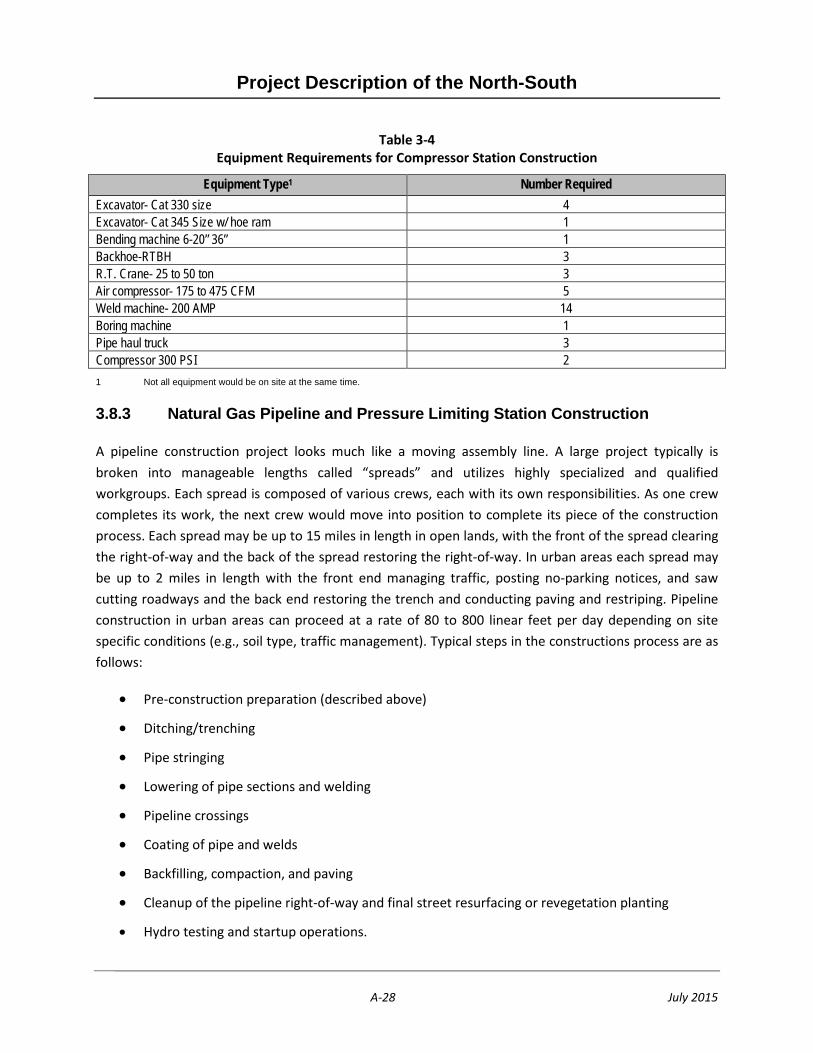
Equipment and Material for Compressor Station Construction
The anticipated equipment requirements for construction of the compressor station are provided in Table 3-4. These estimates are representative of the type and size of construction equipment to be used on this component of the Proposed Project. All construction equipment would be fitted with appropriate mufflers and all engines would be maintained regularly. Welding machines would use diesel or unleaded fuel. Equipment would be mounted on 18-wheel trucks for delivery to the site. The equipment would be deployed and set up for work in approximately one week once site civil work (i.e., access road and grading activities, if required) has been completed.
Table 3-4 Equipment Requirements for Compressor Station Construction
Equipment Type1 Number Required Pickup- ¾ Ton (2WD) 19 1 Ton Flatbed (4WD) 3 1 Ton Weld Truck 13 1 Ton Service/ Utility 1 2 Ton Flatbed (2WD) 10 3 AX Flatbed W/22 + Ton Crane 1 2 Ton Fuel & Lube Truck 1 2 Ton Sandblast 1 3 AX Lowered Tractor 3 3 AX Water Truck 6x6 6 Trailer- Float 1 Trailer- Lowbed 5 Trailer-Office 2 Forklift- 10,000# &Over 1 D-8 Bulldozer 2 D-7 Bulldozer w/ Winch 4 14G Grader 1 Outlaw padder 2 Foam unit 1 Pipelayer- 572 size 2 Pipelayer- 583 size 4
Project Description of the North-South
A-28 July 2015
Table 3-4 Equipment Requirements for Compressor Station Construction
Equipment Type1 Number Required Excavator- Cat 330 size 4 Excavator- Cat 345 Size w/ hoe ram 1 Bending machine 6-20” 36” 1 Backhoe-RTBH 3 R.T. Crane- 25 to 50 ton 3 Air compressor- 175 to 475 CFM 5 Weld machine- 200 AMP 14 Boring machine 1 Pipe haul truck 3 Compressor 300 PSI 2 1 Not all equipment would be on site at the same time.
3.8.3 Natural Gas Pipeline and Pressure Limiting Station Construction
A pipeline construction project looks much like a moving assembly line. A large project typically is broken into manageable lengths called “spreads” and utilizes highly specialized and qualified workgroups. Each spread is composed of various crews, each with its own responsibilities. As one crew completes its work, the next crew would move into position to complete its piece of the construction process. Each spread may be up to 15 miles in length in open lands, with the front of the spread clearing the right-of-way and the back of the spread restoring the right-of-way. In urban areas each spread may be up to 2 miles in length with the front end managing traffic, posting no-parking notices, and saw cutting roadways and the back end restoring the trench and conducting paving and restriping. Pipeline construction in urban areas can proceed at a rate of 80 to 800 linear feet per day depending on site specific conditions (e.g., soil type, traffic management). Typical steps in the constructions process are as follows:
• Pre-construction preparation (described above)
• Ditching/trenching
• Pipe stringing
• Lowering of pipe sections and welding
• Pipeline crossings
• Coating of pipe and welds
• Backfilling, compaction, and paving
• Cleanup of the pipeline right-of-way and final street resurfacing or revegetation planting
• Hydro testing and startup operations.
Project Description of the North-South
A-29 July 2015
The methods of pipeline construction would vary, depending on the location of the construction activities. For example, pipeline construction activities within paved roadways would require pavement breaking, plating, and other activities that would not be required in undeveloped areas. Conversely, pipeline construction in undisturbed areas would vary, depending on topography, proximity to sensitive environmental resources, and other factors. The majority of the proposed alignment would be situated within existing Applicant right-of-way, along other existing utility corridors, and/or along existing paved roads. Illustrations of typical pipeline construction activities that would occur for the Proposed Project are provided on Figure 3-6, Figure 3-7, and Figure 3-8.
A detailed discussion of the typical steps in the pipeline construction process is also discussed below.
Right-of-Way Clearing and Ditching/Trenching
As applicable, USA would notify service providers who would then mark their existing utilities, enabling the contractor to avoid conflict between proposed pipeline and existing below-ground infrastructure. Any required traffic control measures would be installed. Ditching/trenching operations would then begin.
Prior to work in undeveloped areas, surveyors would establish the location of the pipeline and necessary width of the work area by staking and flagging. Clearing would then take place and would involve cutting and removing brush, removing topsoil where possible, and grading the right-of-way to prepare the work area. Topsoil typically would be stockpiled along the edge of the right-of-way. Once the work area has been established, trenching operations would begin.
A typical trench would be 7 to 8 feet deep and 60 inches wide. The total required construction width could be up to 50 feet wide within urbanized areas/paved roadways and up to 300 feet wide within remote rural areas. The ditch would be excavated using backhoes, trenching machines, and track hoes. An exception to the mechanical excavation would be hand digging to locate buried utilities, such as other pipelines, cables, water mains, and sewers.
At the PLS, there will be excavations and trenching within the dimensions of the expanded stations. Excavations and trenching would be 7 to 12 feet deep. An area outside of the footprint of the expanded station would be cleared of brush or vegetation and used for staging and laydown; no excavation would occur.
Fugitive dust emissions at the construction site during earthmoving operations would be controlled by water trucks equipped with fine spray nozzles.
Spoils from excavations, including those from street excavations, would typically be used as shading (six inches of native fill free of rocks) and backfill materials at the site of origin. Excess spoil material along unpaved right-of-way areas in open lands would be spread along the right-of-way. When used for backfill, spoils from the trenches within paved roadways would be hauled to previously disturbed sites for
Project Description of the North-South
A-30 July 2015
temporary storage and screening, if required, to remove any large rocks or debris and then returned to the trench for backfilling. Spoil material that is unsuitable for backfill use and economically unusable for other purposes would be disposed of in available landfills in accordance with local requirements. Any contaminated soil or waste encountered during trenching would be assessed and then removed and disposed of in the nearest available licensed landfills in accordance with applicable regulations.
Pipe Stringing
Pipe-stringing trucks would be used to transport the pipe in 40- to 80-foot lengths from the shipment point or a pipe storage yard to the construction sites. Where sufficient room exists, trucks would carry the pipe along the right-of-way, and side boom tractors would unload the joints of pipe from the stringing trucks and lay them end to end beside the ditch line for future line-up and welding. The pipe would be bent by a portable bending machine to fit the contour of the ditch both vertically and horizontally to accommodate crossing substructures or topography. Pipeline fittings would be used when pipe bends are not feasible.
Lowering of Pipe Sections and Welding
In open lands, pipe sections are normally welded above the trench in pipe strings. The welded pipe strings would be lifted and lowered into the ditch by side boom tractors spaced so that the weight of unsupported pipe would not cause mechanical damage. Cradles with rubber rollers or padded slings would be used so the tractors could lower the pipe without damage as they travel along the ditch line. Laying the pipe would involve the use of line-up clamps that would hold the pipe sections in position until the first welding pass is completed.
In urban areas ditch welds are required whenever the ditch line is obstructed by other utilities and substructures crossing the pipe ditch. These welds would usually be made in the ditch at the final elevation, and each weld would require pipe handling for line-up. Following the line-up crew, the welding crew would apply the remaining weld passes to complete the weld.
Blasting
Pipeline installation may require blasting in certain areas, which would be planned only during daylight hours. Blasting requires the use of small charges that are placed within the pipeline trench alignment in areas where rock prevents trenching using standard construction equipment. Blast holes are typically 2 to 3-inches in diameter and typically 7 to 10 feet deep. Blast charges are precisely determined to limit the pressure and potential for flyrock. A blast plan would be developed to address specifications for the following items: use of explosives; blasting; notification; transportation of blasting material; methods for limiting ground vibrations; air-overpressure levels; records requirements and safety and warning programs; and vibration predictions based on project parameters. Warning measures include audible signals and lookouts to keep the public away from the

Project Description of the North-South
A-31 July 2015
area. The U.S. Department of Labor’s Occupational Safety and Health Administration has detailed safety requirements for each blasting event to ensure worker and public safety.
Pipeline Crossings
Outlined below are the potential construction techniques that may be required in areas where in the proposed alignment would extend over, under, or around riparian areas, culturally sensitive areas, or existing facilities (freeways, roads, railroad tracks, etc.) along the pipeline alignment. Table 3.5 provides information on the estimated number of crossings that would be required for installation of the pipeline.
Directional Drilled Crossings
A typical directional drill work area is illustrated on Figure 3-9. Directional drills typically require a shallow entry and exit pit for each bore. These pits are approximately 10 to 15 feet wide, up to 30 feet long, and 10 feet deep. The work area is usually about 400 feet by 200 feet for the entry pit and 100 feet by 200 feet for the exit pit. Spoils from the excavation would be placed alongside the pits. Spoils would be used as backfill, and wet spoils would be placed in detention basins if uncontaminated and otherwise suitable. The narrative below describes the process used in directional drilling.
To start the bore, a directional drilling rig is positioned at the entry pit and a pilot hole is formed at the beginning of the directional drill crossing. The pilot hole is formed either by excavation or jetting. Depending on the condition of the soil, the pilot is drilled along a predetermined alignment. The typical pilot hole for a pipeline of this size would be approximately 4 inches but can vary depending on the soil conditions and rig size. Drilling fluid is pumped through the drill pipe to the drill head and then jetted through. The end of the drill pipe is used to core the pilot hole. The drill fluid lubricates the drill stem and carries the cuttings to the surface. The entry pit doubles as a capture pit for the returned drilling fluid. The fluid is pumped through a treatment system that separates the cuttings from the fluid and reprocesses the fluid for reuse. The drill fluid is then recycled and re-injected into the drill stem. The pilot process can take several weeks, depending on soil conditions, and may require changing of the drill stem or drill head.
Once the pilot hole has been completed, the second pass would take place with a reamer, or hole opener. The type of opener used depends on soil conditions and soil density. A fly cutter is typically used in good ground conditions. The reaming pass may take several steps depending on the size of the hole. The reamer is attached to the drill string and is rotated and pushed or pulled while rotating, and drill fluid is pumped to the reamer through the drill pipe. The excavated soil is suspended in the drill fluid and then brought to the surface and recycled. When the reamer is attached to the drill string, there would always be a drill pipe on both sides of the reamer, allowing for the drill steel to be in the hole at all times. Several reaming passes may be required.
Project Description of the North-South
A-32 July 2015
After the desired hole has been achieved and the reamer has passed through it completely, a mud pass or packer reamer would be performed to ensure that the hole is clear of all excavated material and that the drill fluid has filled the hole completely to allow for a smooth lubricated pull-back of the pipe.
The final step is to pull the pipe into the reamed hole. A weld cap is installed on the pipe and a swivel is placed attaching the drill string, thus prohibiting rotation of the pipeline. The pipe is pulled backward into the reamed hole. Completion of the directional drill, demobilization, and cleanup then takes place.
Bored Crossings
There would be bored crossing under railroad right-of-way, freeways, flood control channels, drainages, and some roadways depending on final design and on city and state planning review. Either a cased bore or a slick bore technique would be used for the bored crossings. In both types of crossings, a pit is excavated on each side of the facility to be crossed. These pits are typically 10 to 15 feet wide, up to 50 feet long, and 30 feet deep. The work area typically required is approximately 200 feet by 100 feet for the entry pit and 100 feet by 100 feet for the exit pit. Depth of the pits would depend on final pipeline depth.
For a cased bore, a steel casing would be used to encase the bored pipeline. The casing would be carbon steel pipe and would be coated and electrically isolated from the pipeline cathodic protection system. The method of installation would involve a horizontal boring machine with augers placed within the casing pipe as it is pushed into the opening made by the boring machine. Casing sections would be welded and inspected in the pit prior to boring. The carrier pipe would be inserted into the casing pipe after the casing is completed.
For a slick bore, the method of installation would involve use of the carrier pipe as temporary casing as it is pushed into the opening made by the boring machine. The temporary carrier pipe is replaced with the final carrier pipe once the hole is completed, eliminating the need for a casing. Examples of typical boring cross sections are shown on Figures 3-10 and 3-11.
Bridge Crossings
Installing the proposed pipeline across bridge would require expanding and reinforcing existing openings or cutting and reinforcing new openings in the bridge abutments and lateral diaphragms. At the bridge abutments, casing would be installed to allow for seismic movement between the bridge and the ground.
The pipeline would be installed between the bridge girders and would typically be situated on rollers connected to steel braces that would be attached to the bridge girders. The rollers would be used to aid in the installation of the pipeline and would hold the pipeline in place after installation. Review of the original bridge drawings and preliminary engineering indicate that supporting the pipeline from the existing bridges and providing the necessary reinforcement to each bridge would be feasible. Plans for
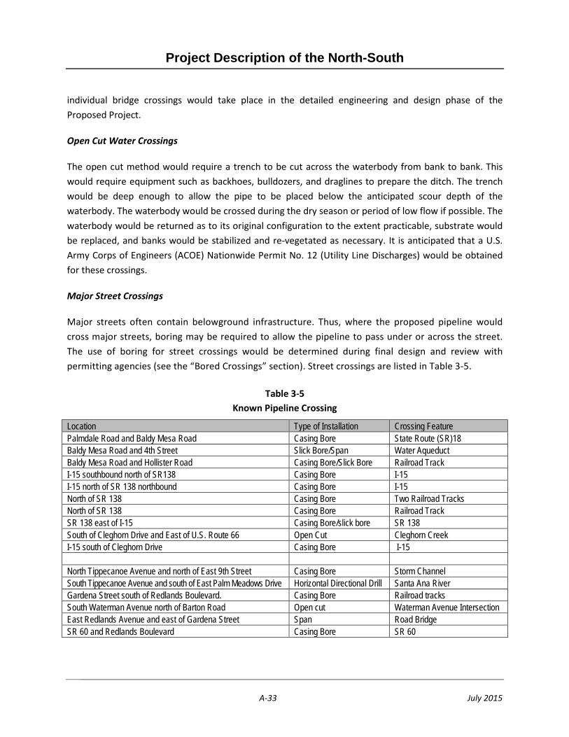
Project Description of the North-South
A-33 July 2015
individual bridge crossings would take place in the detailed engineering and design phase of the Proposed Project.
Open Cut Water Crossings
The open cut method would require a trench to be cut across the waterbody from bank to bank. This would require equipment such as backhoes, bulldozers, and draglines to prepare the ditch. The trench would be deep enough to allow the pipe to be placed below the anticipated scour depth of the waterbody. The waterbody would be crossed during the dry season or period of low flow if possible. The waterbody would be returned as to its original configuration to the extent practicable, substrate would be replaced, and banks would be stabilized and re-vegetated as necessary. It is anticipated that a U.S. Army Corps of Engineers (ACOE) Nationwide Permit No. 12 (Utility Line Discharges) would be obtained for these crossings.
Major Street Crossings
Major streets often contain belowground infrastructure. Thus, where the proposed pipeline would cross major streets, boring may be required to allow the pipeline to pass under or across the street. The use of boring for street crossings would be determined during final design and review with permitting agencies (see the “Bored Crossings” section). Street crossings are listed in Table 3-5.
Table 3-5 Known Pipeline Crossing
Location Type of Installation Crossing Feature Palmdale Road and Baldy Mesa Road Casing Bore State Route (SR)18 Baldy Mesa Road and 4th Street Slick Bore/Span Water Aqueduct Baldy Mesa Road and Hollister Road Casing Bore/Slick Bore Railroad Track I-15 southbound north of SR138 Casing Bore I-15 I-15 north of SR 138 northbound Casing Bore I-15 North of SR 138 Casing Bore Two Railroad Tracks North of SR 138 Casing Bore Railroad Track SR 138 east of I-15 Casing Bore/slick bore SR 138 South of Cleghorn Drive and East of U.S. Route 66 Open Cut Cleghorn Creek I-15 south of Cleghorn Drive Casing Bore I-15 North Tippecanoe Avenue and north of East 9th Street Casing Bore Storm Channel South Tippecanoe Avenue and south of East Palm Meadows Drive Horizontal Directional Drill Santa Ana River Gardena Street south of Redlands Boulevard. Casing Bore Railroad tracks South Waterman Avenue north of Barton Road Open cut Waterman Avenue Intersection East Redlands Avenue and east of Gardena Street Span Road Bridge SR 60 and Redlands Boulevard Casing Bore SR 60

Project Description of the North-South
A-34 July 2015
Coating of Pipe and Welds
Fusion-bonded epoxy coating would be applied at the pipe/coating mill before delivery to the construction site. However, field coating would be necessary on all field weld joints made at the site in order to provide a continuous coating along the pipeline. After the pipe has been welded and inspected, field-applied fusion-bonded epoxy or two-part epoxy would be used for protection of pipe joints. Alternately, construction-grade tape and tape primer may be used. Pipe coating for slick bore and horizontal directional drill installations would be coated with a fusion-bonded epoxy coating with additional thickness. This would protect the pipeline from scratches and abrasions during bored installations.
Weld and Pipe Coating Testing and Inspection
All field welding would be performed by qualified welders in accordance with all applicable ordinances, rules, and regulations, including API 1104 (Standard for Welding Pipe Lines and Related Facilities and the rules and regulations of the U.S. Department of Transportation found in 49 CFR 192 (for natural gas pipelines)). As a safety precaution, a minimum of one 20-pound dry chemical unit fire extinguisher would accompany each welding truck on the job.
Radiographs would be recorded and interpreted for acceptability according to requirements of API 1104. All rejected welds would be repaired or replaced as necessary and re-inspected. The test reports as well as a record indicating the location of the field welds would be kept for the life of the pipeline.
Testing would be conducted to locate any coating discontinuities, such as thinning or mechanical defects, which have the potential to allow moisture to reach the pipe. The testing device would be an electronic holiday detector, which develops an electrical potential between the pipe and an electrode in contact with the outside of the coating. Pinholes in the coating of microscopic size can be located using the electrical detector. All coated pipe, including field joints, fittings, and bends would be tested as the pipe is lowered into the trench and repaired as necessary prior to backfilling.
In addition to the standard pipe mill testing of all pipe and fittings, hydrostatic testing would be performed after construction and prior to startup. Federal regulations (49 CFR 192) mandate hydrostatic testing of new, cathodically protected natural gas pipelines prior to placing the line into operation.
Visual Inspection
The pipeline construction phases would be visually inspected in accordance with U.S. Department of Transportation requirements (49 CFR 192).
Project Description of the North-South
A-35 July 2015
Backfilling, Compaction, and Paving
Backfill material would be obtained from the ditch spoils. The pipe would be covered along its sides and its top with a minimum of 6 inches of native fill free of rocks. This area of fill is referred to as the pipeline shading. In certain areas where damage might occur to the pipe coating from abrasive rocky soils in the trench bottom, clean sand or earth backfill would be used to pad the trench. Any additional padding material would be obtained from local commercial sources. The backfill in the remainder of the trench above the padding and shading would be native material excavated during trenching. The backfilled earth would be compacted using hydraulic equipment and tamper for smaller excavations. The trench would be filled with sand/cement slurry where required by local permitting agencies. The slurry would be purchased from a local slurry plant and transported to the site. Steel plates would be used to cover any open trench within traffic lanes, as required by local permitting agencies. The potential volume of contaminated soils that would be encountered is unknown at this stage of the Proposed Project.
Cathodic Protection System
As discussed in Section 3.5.5, a cathodic protection system consisting of cathodic protection rectifiers, buried anodes, and test stations would be installed along the pipeline. This system would prevent external corrosion of the pipeline. It is anticipated that two rectifiers would be installed along the proposed pipeline. Each of the sites where the rectifiers are installed would require a utility pole, an electrical meter, and a rectifier. Buried anodes would be installed by drilling a hole into the earth to a prescribed depth and then inserting the anodes into the hole.
Restoration of the Pipeline Right-of-Way and Final Street Resurfacing
When compaction of the trench has been completed, the pipeline right-of-way would be restored to its original condition to the extent possible. The right-of-way would be cleared of all construction-related materials and equipment. In areas where the pipeline was installed across non-paved surfaces, the ground surface would be returned to the surrounding condition and topsoil removed during grading of the right-of-way would be spread across the work area. If the pipeline route crosses farm land, the landowner would be compensated for any crop loss due to construction of the pipeline. In areas where the pipeline would be installed across pavement, the ground surface would be repaved in accordance with standard industry practices.
Revegetatation
In natural areas along the pipeline alignment, restoration of the landcape would occur. In the SBNF, restoration would take into account scenery as a fully integrated part of the ecosystems of National Forest System lands. Vegetation restoration would be coordinated once the ROW has been restored considering seasonal timing. After installation of each small segment of the pipeline is complete, restoration would start immediately, involving both the contours of affected ridgelines and restoration
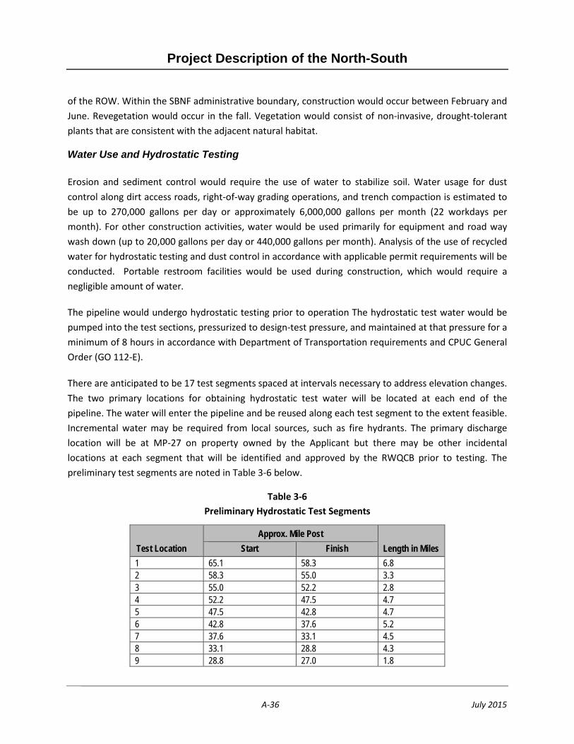
Project Description of the North-South
A-36 July 2015
of the ROW. Within the SBNF administrative boundary, construction would occur between February and June. Revegetation would occur in the fall. Vegetation would consist of non-invasive, drought-tolerant plants that are consistent with the adjacent natural habitat.
Water Use and Hydrostatic Testing
Erosion and sediment control would require the use of water to stabilize soil. Water usage for dust control along dirt access roads, right-of-way grading operations, and trench compaction is estimated to be up to 270,000 gallons per day or approximately 6,000,000 gallons per month (22 workdays per month). For other construction activities, water would be used primarily for equipment and road way wash down (up to 20,000 gallons per day or 440,000 gallons per month). Analysis of the use of recycled water for hydrostatic testing and dust control in accordance with applicable permit requirements will be conducted. Portable restroom facilities would be used during construction, which would require a negligible amount of water.
The pipeline would undergo hydrostatic testing prior to operation The hydrostatic test water would be pumped into the test sections, pressurized to design-test pressure, and maintained at that pressure for a minimum of 8 hours in accordance with Department of Transportation requirements and CPUC General Order (GO 112-E).
There are anticipated to be 17 test segments spaced at intervals necessary to address elevation changes. The two primary locations for obtaining hydrostatic test water will be located at each end of the pipeline. The water will enter the pipeline and be reused along each test segment to the extent feasible. Incremental water may be required from local sources, such as fire hydrants. The primary discharge location will be at MP-27 on property owned by the Applicant but there may be other incidental locations at each segment that will be identified and approved by the RWQCB prior to testing. The preliminary test segments are noted in Table 3-6 below.
Table 3-6 Preliminary Hydrostatic Test Segments
Test Location Approx. Mile Post
Length in Miles Start Finish 1 65.1 58.3 6.8 2 58.3 55.0 3.3 3 55.0 52.2 2.8 4 52.2 47.5 4.7 5 47.5 42.8 4.7 6 42.8 37.6 5.2 7 37.6 33.1 4.5 8 33.1 28.8 4.3 9 28.8 27.0 1.8

Project Description of the North-South
A-37 July 2015
Test Location Approx. Mile Post
Length in Miles Start Finish 10 27.0 22.5 4.5 11 22.5 20.4 2.1 12 20.4 17.0 3.5 13 17.0 15.6 1.3 14 15.6 14.8 0.8 15 14.8 12.4 2.4 16 12.4 6.5 6.0 17 6.5 0.0 6.5
Water may obtained from local hydrants, canals, aqueducts, or water wells available along the construction route. Non-potable water would be sampled and analyzed prior to use. Agencies or private owners would be contacted and each water source approved prior to establishing connection.
Approximately 10.5 million gallons of water would be required to test the pipeline.Once detailed engineering drawings have been completed, the quantity of water needed would be refined. Once the test has been completed on the initial segment, the water would be transferred to the next section of pipe and reused for testing purposes where possible then ultimately discharged in accordance with all applicable permits and landowner approvals and in a manner that would minimize erosion.
3.8.5 Access Roads and Staging and Work Areas
Access Roads
Within undeveloped areas, existing access roads would be used to the extent possible. The existing dirt access roads from the paved roadway accessing the pipeline right-of-way may require additional grading to allow for construction equipment and pipe access. Existing access roads along the pipeline routes vary from 8 feet wide to 15 feet wide. Grading of these roads may be required to properly level the road. Additionally, roads would be widened as necessary at sharp turns to accommodate construction equipment and materials. Approximate final width of graded roads would be 15 to 30 feet. Soil removed during grading would be stockpiled adjacent to the access road and access roads would be restored to the extent possible following construction.
The proposed pipeline route generally follows closely along existing access roads within SoCalGas pipeline right-of-way and other utility corridors. These access roads, where possible, would be used as part of the graded work area of the construction right-of-way, thus reducing the total impact acreage. Upon completion of construction, the existing access roads would then be reestablished within the work area where necessary.
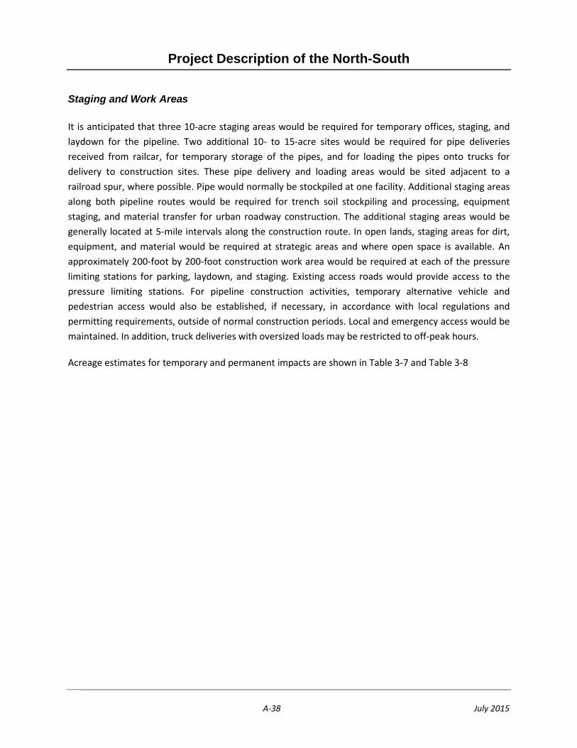
Project Description of the North-South
A-38 July 2015
Staging and Work Areas
It is anticipated that three 10-acre staging areas would be required for temporary offices, staging, and laydown for the pipeline. Two additional 10- to 15-acre sites would be required for pipe deliveries received from railcar, for temporary storage of the pipes, and for loading the pipes onto trucks for delivery to construction sites. These pipe delivery and loading areas would be sited adjacent to a railroad spur, where possible. Pipe would normally be stockpiled at one facility. Additional staging areas along both pipeline routes would be required for trench soil stockpiling and processing, equipment staging, and material transfer for urban roadway construction. The additional staging areas would be generally located at 5-mile intervals along the construction route. In open lands, staging areas for dirt, equipment, and material would be required at strategic areas and where open space is available. An approximately 200-foot by 200-foot construction work area would be required at each of the pressure limiting stations for parking, laydown, and staging. Existing access roads would provide access to the pressure limiting stations. For pipeline construction activities, temporary alternative vehicle and pedestrian access would also be established, if necessary, in accordance with local regulations and permitting requirements, outside of normal construction periods. Local and emergency access would be maintained. In addition, truck deliveries with oversized loads may be restricted to off-peak hours.
Acreage estimates for temporary and permanent impacts are shown in Table 3-7 and Table 3-8

Project Description of the North-South
A-1 July 2015
Table 3-7 Temporary and Permanent Acreage Disturbance by Segment
Type Segment 1 Segment 2 Segment 3 Segment 4 Total Access Road (Temporary Impacts) Acreage 14.99 20.68 0 4.75 40.42 Access Road (Permanent Impacts) Acreage 0 0 0 0.95 0.95
Staging Areas Acreage 35.37 11.49 54.82 39.29 140.97
Table 3-8 Temporary and Permanent Acreage Disturbance by Milepost
Type Mile Posts
0.0-5.0 5.0-10.0 10.0-15.0 15.0-20.0
20.0-25.0
25.0-30.0
30.0-35.0
35.0-40.0
40.0-45.0
45.0-50.0
50.0-55.0
55.0-60.0 60.0-65.0 Total
Access Road (Temporary Impacts) Acreage 9.54 0 10.51 12.98 2.68 0 0 0 0 0 0 4.75 0 40.46 Access Road (Permanent Impacts) Acreage 0 0 0 0 0 0 0 0 0 0 0 0.95 0 0.95
Staging Areas Acreage 0.23 26.43 9.46 2.15 0.38 10.77 16.77 2.64 16.03 13.11 9.87 6.45 26.69 140.98

Project Description of the North-South
A-1 July 2015
Equipment and Material for Pipeline Construction
The equipment requirements estimated for pipeline construction are given in Table 3-6. These estimates are representative of the type and size of construction equipment to be used during Proposed Project construction. All construction equipment would be fitted with appropriate mufflers and all engines would be maintained regularly. Welding machines would use diesel or unleaded fuel. Equipment would be mounted on 18-wheel trucks for delivery to the site. The equipment would be deployed and set up for work in approximately one week, as soon as access roads have been established and grading activities have been completed, where required. Equipment is assumed to be in conformance with Tier 3 standards.
Materials that would be truck-transported to the site would include coated pipe sections (40 to 80 feet each), pipe fittings, valve assemblies, valve vaults, trench shoring pile, coating supplies (for weld-joints), welding materials, cement, aggregate, gravel, sand, and slurry (from local plants) for backfill at street crossings, asphalt for repaving, signs and fencing, fuel and lubrication for equipment, drinking water, and water for dust control. The amount of each material needed would depend on the location and activity of the spread at any given time. Anticipated equipment for typical pipeline construction is outlined in Table 3-9.
Table 3-9 Equipment Requirements for Pipeline Construction (per Spread)
Equipment Type1 Number Required Pickup truck- ¾ Ton (2WD) 20 1 Ton Flatbed (4WD) 3 1 Ton Weldtruck 14 1 Ton Service/Utility 3 2 Ton Flatbed (2WD) 9 3 AX Flatbed w/22 + Ton Crane 2 2 Ton Fuel & Lube Truck 1 2 Ton Sandblast 2 3 AX Lowbed Tractor 5 3 AX Water Truck 6x6 2 Hydroexcavator Truck Mounted 1 Trailer-Float 1 Trailer-Lowbed 5 Trailer-Office 2 Forklift- 10,000# & Over 2 Pipelayer-572 size 3 Pipelayer- 583 size 2 Excavator- Cat 330 size 1 Bending machine 6”-20” 36” 1 Backhoe- RTBH 6 R.T. Crane- 25 to 50 Ton 4

Project Description of the North-South
A-2 July 2015
Table 3-9 Equipment Requirements for Pipeline Construction (per Spread)
Equipment Type1 Number Required Air Compressor- 17 to 475 CFM 8 Air Comp- 1,500 CFM 2 Weld Machine- 200 AMP 14 Mud System 1 Pump-Fill 1 Pump-Hydro/Test 1 Triplex Pump 1 Godwin 6” Pump 2 Light Tower 6 Drilling 750,000# 1 Power Generator 3 Boring Machine 1 Pipe Haul Truck 2 Saw 2 12 CY Dump Truck 29 Roller 5 Ton 2 Street Sweeper 2 Grinding Machine 1 Paving Machine 1 Compressor 300 PSI 2 1 Equipment needed may vary depending on construction needs, type of construction, and whether construction would take place in urban or
open land.
The Applicant intends to use horizontal directional drilling (HDD) in certain locations to minimize potential impacts to waterways and transportation infrastructure. HDD technology requires certain unique equipment that would not otherwise be used for typical pipeline construction. Table 3-10 depicts the equipment typically required for HDD, and an illustration of a typical HDD construction site is shown on Figure 3-9.
Table 3-10 Equipment Requirements for Each HDD
Equipment Type1 Number Required Drill rig 1 Mud pumps 2–4 Mud mixing tanks 1–2 Power trailers (to drive rig hydraulics) 2 Hose rack 1 Generator 1 Control van 1 Modular drill pipe and storage rack set 1 Stores container 1 Baker tank 1
Project Description of the North-South
A-3 July 2015
Table 3-10 Equipment Requirements for Each HDD
Equipment Type1 Number Required Crane 1 Backhoe 1 1 Equipment needed may vary depending on length and soil and geotechnical characteristics.
3.8.6 Proposed Project Construction Work Hours, Schedule, and Workforce
This subsection provides an overview of the construction schedule for the Proposed Project. Estimated work hours, schedule, and construction workforce are outlined below.
Work Hours
Construction activities on the Adelanto Compressor Station would typically occur Monday through Friday, and some Saturdays, between the hours of 7:00 AM and 7:00 PM or as allowed by the City of Adelanto’s zoning ordinance, depending on weather and material delivery. Construction of the pipeline in areas with sensitive receptors would normally take place 5 days per week between the hours of 6:00 AM and 7:00 PM. In undeveloped areas where no sensitive receptors are located nearby, construction of the pipeline would normally take place 6 days per week between the hours of 6:00 AM to 7:00 PM, unless modified due to traffic constraints and approved by the applicable jurisidiction. Night and weekend construction may be necessary in urban areas to minimize impacts to traffic and industrial or commercial business activities but would only occur to the extent that such construction is permitted in accordance with local ordinances. Additionally, during hydrostatic testing and start-up operations, work hours may extend up to 24 hours per day during any day of the week to the extent permitted in accordance with local ordinances. Construction adjacent to sensitive noise receptors such as residences and recreational facilities would be conducted in accordance with local noise ordinances and permit requirements. Operational noise excluding emergency work associated with pipeline depressurization activities is typically completed within four to five hours and at 60-70 dBA with a silencer.
Schedule
Construction and installation of the proposed modifications at the Adelanto Compressor Station would take approximately 18 months to complete. The entire planning and construction process for the Adelanto Compressor Station, including engineering, design, and procurement, is estimated to last 30 months. Construction and installation of the proposed pipeline would take approximately 19 months. The entire planning and construction process, including engineering, design, and procurement, is estimated to last 36 months. Design and construction of the Proposed Project, including mobilization, demobilization, and restoration, is anticipated to take approximately 3 years. Table 3-11 provides an overview of the schedule.

Project Description of the North-South
A-4 July 2015
Table 3-11 Proposed Construction Timeline
Adelanto Compressor Station Timeline Mobilization 1 month Construction 12 months Tie-in and startup operations 1 month Project operational 4 months Post-construction restoration 1 month Demobilization 1 month
Adelanto to Moreno Pipeline Timeline Mobilization 1 month (multiple spreads) Dirt right-of-way preparation 6 months (ongoing, multiple spreads) Pipeline construction open land 7 months (multiple spreads) Pipeline construction urban areas 13 months (multiple spreads) Hydrostatic testing 2 months Tie-in and startup operations 1 month Project operational 16 months Post-construction restoration 18 months Demobilization 1 month Pressure Liming Stations Timeline Mobilization 1 week Excavation 1 month Fabrication 2 months Hydrostatic testing 1 month Installation, tie-in, and startup operations 4 months Project operational 8 months Post-construction restoration 2 weeks Demobilization 1 week Note All durations are approximate.
Proposed Construction Timeline by Milepost
Koala to Baldy Mesa (MP 0.0-12.0) Timeline Mobilization 2 weeks Excavate Trench 5 months Install Pipe 5 months Backfill 5 months Demobilize 1 month Supervision 6 months
National Forrest (MP 12.0-22.2) Timeline Mobilization 1 month Excavate Trench 4 months Line up- Lay Pipe 5 months Backfill 3 months Demobilize 1 month Supervision 5 months
Route 66 (MP 22.2-32.0) Timeline

Project Description of the North-South
A-5 July 2015
Mobilization 1 month Excavate Trench 5 months Install Pipe 4 months Backfill 5 months Demobilize 1 month Supervision 6 months Test, Clean & Dry All Job 2 months
South Gardena Street to Kendall (MP 45.0-32.0) Timeline Mobilization 2 weeks Excavate Trench 11 months Install Pipe 5 months Backfill 1 month Demobilize 1 month Supervision 1 month
Reche Canyon (MP 49.0-45.0) Timeline Mobilization 1 month Excavate Trench 3 months Install Pipe 3 months Backfill 3 months Demobilize 1 month Supervision 4 months
Reche Canyon (MP 55.8-49.0) Timeline Mobilization 2 weeks Excavate Trench 8 months Install Pipe 8 months Backfill 8 month Demobilize 1 month Supervision 10 months
Moreno (MP 65.1-55.8) Timeline Mobilization 1 month Excavate Trench 4 months Line up- Lay pipe 5 months Backfill 4 months Demobilize 1 month Supervision 5 months Note All durations are approximate.
Proposed Project Workforce
The Proposed Project would generate construction-related employment opportunities, especially for skilled workers such as welders. Local workforce would be utilized when possible. Workforce needed may vary depending on construction needs, type of construction, and whether construction would take place in urban or undeveloped land. The Applicant expects direct and indirect economic benefits resulting from job creation and project-related expenditures in the communities affected by the Proposed Project.
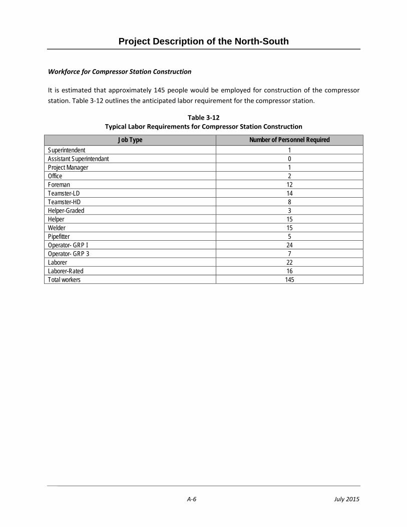
Project Description of the North-South
A-6 July 2015
Workforce for Compressor Station Construction
It is estimated that approximately 145 people would be employed for construction of the compressor station. Table 3-12 outlines the anticipated labor requirement for the compressor station.
Table 3-12 Typical Labor Requirements for Compressor Station Construction
Job Type Number of Personnel Required Superintendent 1 Assistant Superintendant 0 Project Manager 1 Office 2 Foreman 12 Teamster-LD 14 Teamster-HD 8 Helper-Graded 3 Helper 15 Welder 15 Pipefitter 5 Operator- GRP I 24 Operator- GRP 3 7 Laborer 22 Laborer-Rated 16 Total workers 145

Project Description of the North-South
A-7 July 2015
Workforce for Pipeline Construction
It is estimated that approximately 167 people per spread would be employed for construction of the pipeline. Local qualified workforce would be utilized to the extent available and based upon experience and availability. Table 3-13 outlines the anticipated labor requirement for the pipeline construction.
Table 3-13 Typical Labor Requirements for Pipeline Construction (per Spread)
Job Type Number of Personnel Required Superintendent 1 Assistant Superintendant 1 Project Manager 1 Office 2 Foreman 12 Teamster-LD 10 Teamster-HD 29 Helper-Graded 1 Helper 13 Welder 13 Pipefitter 7 Operator-GRP 1 27 Operator-GRP 3 5 Laborer 27 Laborer-Rated 18
Total Workers Per Spread 167
Workforce for Directional Drilling
A typical crew for a directional drill associated with the Proposed Project would consist of approximately 20 contractor personnel. The personnel required would include a crew for welding and testing of the pipe string, a crew that would operate the drill rig and other equipment, and subcontractors such as radiographic testers. Table 3-14 outlines the anticipated labor requirement for directional drilling (per spread) below.
-
Table 3-14 Typical Labor Requirements for Directional Drilling (per Spread)
Equipment Type Number Required Drill rig 1 Mud pumps 2–4 Mud mixing tanks 1–2 Power trailers (to drive rig hydraulics) 2 Hose rack 1 Generator 1 Control van 1

Project Description of the North-South
A-8 July 2015
Table 3-14 Typical Labor Requirements for Directional Drilling (per Spread)
Equipment Type Number Required Modular drill pipe and storage rack set 1 Stores container 1 Baker tank 1 Crane 1 Backhoe 1
3.9 Post-Construction Project Operations
This section describes what activities would occur once the compressor station and pipeline are operational.
Compressor Station and Pressure Limiting Stations
Compressor stations are designed to be remotely operated in a safe and efficient manner. There is no requirement for employees to be at the site during normal operation, although the sites are checked regularly by operations personnel who monitor, inspect and maintain the equipment. Processes are continuously monitored from a centralized control center. Unique compressor station maintenance activities are described below. Routine maintenance activities will be conducted on weekly, monthly, quarterly and annual basis.
Emergency Shut Down
Operations and maintenance of the Adelanto Compressor Station emergency shut down (ESD) system occurs once a year, in accordance with 49 CFR 192.731(c). The ESD system would be tested to ensure it operates properly. The test will result in an actual station blow down.
Filter Separator Inspection
Filter separator inspections will occur when the valves on the inlet and outlet sides of the filter separator would be closed and the filter separator de-pressurized to safely open it for inspection and filter replacement. This is conducted on an as-needed basis, but usually infrequently.
.
Pipeline
SoCalGas operates approximately 100,270 miles of interconnecting pipelines within the service territory that transport natural gas to residential, commercial, industrial, and utility electric generating customers
Project Description of the North-South
A-9 July 2015
throughout Central and Southern California. The system consists of high-, medium-, and low-pressure pipelines and includes appurtenant and support facilities, such as compressor stations, natural gas storage fields, numerous valve and metering stations, cathodic protection equipment, and aerial and ground markers, as well as telecommunications equipment and access roads. To assure that the pipeline system operates in compliance with environmental and safety regulations, SoCalGas performs routine O&M activities and upgrades throughout the system.
The North South project will be operated and maintained in accordance with CPUC General Order 112-E, which incorporates the Federal Pipeline Safety Regulations under Title 49 of the Code of Federal Regulations, Parts 190, 191, 192, 193, and 199. SoCalGas activities include, without limitation, all current and future actions arising out of, or in any way connected with the siting (including any site assessment, surveying, testing, or planning), design, installation, construction, use, maintenance, operation, repair and removal of facilities within the service territory. Table 3-15 lists the Covered Activities that will occur in association with the Project and along and adjacent to its rights-of-way (ROWs). These activities have been grouped into five general categories, and include activities that are performed on a regular basis at a given location (“regularly re-occurring activities”) as well as those that are rarely, if ever, repeated at a given location (“non-recurring activities”). Unless otherwise noted, activities described for pipelines are also relevant to pressure limiting stations. Compressor station activities are described separately.
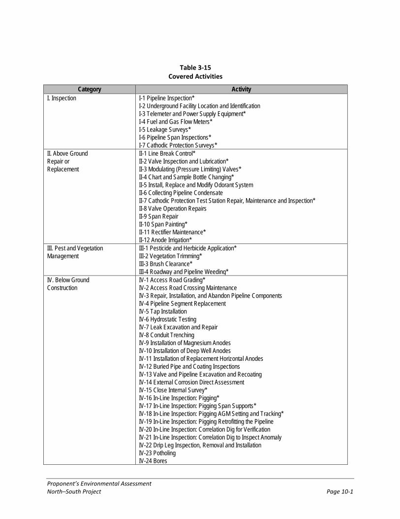
Proponent’s Environmental Assessment North–South Project Page 10-1
Table 3-15 Covered Activities
Category Activity I. Inspection
I-1 Pipeline Inspection* I-2 Underground Facility Location and Identification I-3 Telemeter and Power Supply Equipment* I-4 Fuel and Gas Flow Meters* I-5 Leakage Surveys* I-6 Pipeline Span Inspections* I-7 Cathodic Protection Surveys*
II. Above Ground Repair or Replacement
II-1 Line Break Control* II-2 Valve Inspection and Lubrication* II-3 Modulating (Pressure Limiting) Valves* II-4 Chart and Sample Bottle Changing* II-5 Install, Replace and Modify Odorant System II-6 Collecting Pipeline Condensate II-7 Cathodic Protection Test Station Repair, Maintenance and Inspection* II-8 Valve Operation Repairs II-9 Span Repair II-10 Span Painting* II-11 Rectifier Maintenance* II-12 Anode Irrigation*
III. Pest and Vegetation Management
III-1 Pesticide and Herbicide Application* III-2 Vegetation Trimming* III-3 Brush Clearance* III-4 Roadway and Pipeline Weeding*
IV. Below Ground Construction
IV-1 Access Road Grading* IV-2 Access Road Crossing Maintenance IV-3 Repair, Installation, and Abandon Pipeline Components IV-4 Pipeline Segment Replacement IV-5 Tap Installation IV-6 Hydrostatic Testing IV-7 Leak Excavation and Repair IV-8 Conduit Trenching IV-9 Installation of Magnesium Anodes IV-10 Installation of Deep Well Anodes IV-11 Installation of Replacement Horizontal Anodes IV-12 Buried Pipe and Coating Inspections IV-13 Valve and Pipeline Excavation and Recoating IV-14 External Corrosion Direct Assessment IV-15 Close Internal Survey* IV-16 In-Line Inspection: Pigging* IV-17 In-Line Inspection: Pigging Span Supports* IV-18 In-Line Inspection: Pigging AGM Setting and Tracking* IV-19 In-Line Inspection: Pigging Retrofitting the Pipeline IV-20 In-Line Inspection: Correlation Dig for Verification IV-21 In-Line Inspection: Correlation Dig to Inspect Anomaly IV-22 Drip Leg Inspection, Removal and Installation IV-23 Potholing IV-24 Bores
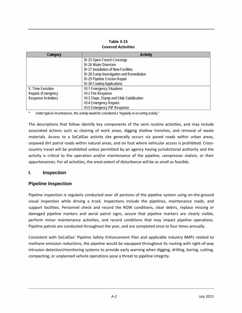
A-2 July 2015
Table 3-15 Covered Activities
Category Activity IV-25 Open-Trench Crossings IV-26 Water Diversion IV-27 Installation of New Facilities IV-28 Sump Investigation and Remediation IV-29 Pipeline Erosion Repair IV-30 Coating Applications
V. Time-Sensitive Repairs (Emergency Response Activities)
VI-1 Emergency Situations VI-2 Fire Response VI-3 Slope, Slump and Slide Stabilization VI-4 Emergency Repairs VI-5 Emergency PIP Response
* Under typical circumstances, this activity would be considered a “regularly re-occurring activity.”
The descriptions that follow identify key components of the semi routine activities, and may include associated actions such as clearing of work areas, digging shallow trenches, and removal of waste materials. Access to a SoCalGas activity site generally occurs via paved roads within urban areas, unpaved dirt patrol roads within natural areas, and on foot where vehicular access is prohibited. Cross-country travel will be prohibited unless permitted by an agency having jurisdictional authority and the activity is critical to the operation and/or maintenance of the pipeline, compressor station, or their appurtenances. For all activities, the areal extent of disturbance will be as small as feasible.
I. Inspection
Pipeline Inspection
Pipeline inspection is regularly conducted over all portions of the pipeline system using on-the-ground visual inspection while driving a truck. Inspections include the pipelines, maintenance roads, and support facilities. Personnel check and record the ROW conditions, clear debris, replace missing or damaged pipeline markers and aerial patrol signs, assure that pipeline markers are clearly visible, perform minor maintenance activities, and record conditions that may impact pipeline operations. Pipeline patrols are conducted throughout the year, and are completed once to four times annually.
Consistent with SoCalGas’ Pipeline Safety Enhancement Plan and applicable industry BMPs related to methane emission reductions, the pipeline would be equipped throughout its routing with right-of-way intrusion detection/monitoring systems to provide early warning when digging, drilling, boring, cutting, compacting, or unplanned vehicle operations pose a threat to pipeline integrity.

A-3 July 2015
Underground Facility Location and Identification
State law requires that every person planning an excavation must first advise a regional notification center of the excavation location. The regional notification center then requires operators of underground pipelines and other underground facilities in the area to locate and mark their facilities to avoid damage during excavation (California Government Code Section 2416, et seq.). In compliance with this law, and for the protection of the public and to ensure safe operation of the pipeline, SoCalGas has dedicated personnel that respond to locate and mark the pipeline, and provide on-site surveillance during construction activities near the pipelines. These employees will utilize four-wheel drive, rubber-tired pickup trucks and locating equipment to conduct this task. This activity can occur at any time during the year, and anywhere along the right-of-way.
Telemeter and Power Supply Equipment
Telemeters are used for remote sensing of pipelines. Telemeters and power supply equipment are located at main line valve stations, which are typically 8 to 10 miles apart. Both the telemeter and the power supply equipment require monthly inspections to ensure that they are functioning properly. This activity can occur throughout the year, and is an ongoing process.
Fuel and Gas Flow Meters
Fuel and flow meters measure the flow of gas through the pipeline. These meters must be inspected each month to ensure that they maintain their integrity and accuracy. Fuel and gas flow meters are located at main line valve stations. This activity can occur throughout the year, and is an ongoing process.
Leakage Surveys
Gas leak surveys are conducted on pipelines. These surveys are conducted once each year, or more if needed. Leakage survey activities are regularly conducted over all portions of the pipeline system using a combination of on-the-ground visual inspection while driving a truck, as well as truck mounted leak detection equipment. This activity occurs throughout the year for the entire system.
Cathodic Protection Surveys
Cathodic protection surveys are completed bi-monthly and determine pipe and soil electrical potentials. Surveys are performed to ensure that the system is operating effectively. Simple testing instruments are needed, and typical surveys require 10 days (dependent on weather conditions) to complete. Surveys are conducted bimonthly throughout the year.

A-4 July 2015
Line Break Control
Line break controls on valve actuators are inspected and calibrated twice annually. Line break controller inspections and calibrations are normally completed within five to ten days for the entire pipeline system each year. A small crew in a pickup truck using various test instruments completes the work. This activity can occur at any time during the year.
Valve Inspection and Lubrication
Valve inspection, lubrication, and general maintenance are completed annually but can occur more frequently depending upon a particular valve’s classification as critical or non-critical. General maintenance includes removing weeds and debris from the valve station enclosures, and touch-up painting of valves and related equipment using lead-free paint. Herbicides are only used near equipment and inside fences on disturbed or previously cleared land. Herbicides are used minimally, in accordance with the manufacturer’s product label, and as recommended by a State Certified Pest Control Advisor. Valve inspection, lubrication, and maintenance activities occur throughout the year.
Modulating (Pressure Limiting) Valves
Modulating valves regulate the flow of gas through a pipeline. These valves are inspected and lubricated every two weeks throughout the year to ensure that they are functioning properly. Equipment used for this activity includes a three-ton, six wheeled rubber-tired truck and lubricating equipment. One operator typically completes this task. This activity can occur throughout the year, and is an ongoing process.
II. Above-Ground Repair/Replacement
Enhanced Pipeline Monitoring
To further support the early detection and management of potential gas releases, gas detection sensors would be employed at key locations along the alignment. These sensors are particularly important where the alignment would be situated near earthquake faults or in proximity to facilities that pose special consideration for evacuation and/or commerce impact in the event of a pipeline incident. Up to 30 monitoring locations would be installed
Valve Inspection and Lubrication
Valve inspection, lubrication, and general maintenance are completed annually but can occur more frequently depending upon a particular valve’s classification as critical or non-critical. General maintenance includes removing weeds and debris from the valve station enclosures, and touch-up painting of valves and related equipment using lead-free paint. Herbicides are only used near equipment and inside fences on
A-5 July 2015
disturbed or previously cleared land. Herbicides are used minimally, in accordance with the manufacturer’s product label, and as recommended by a State Certified Pest Control Advisor. Valve inspection, lubrication, and maintenance activities occur throughout the year.
Modulating (Pressure Limiting) Valves
Modulating valves regulate the flow of gas through a pipeline. These valves are inspected and lubricated every two weeks throughout the year to ensure that they are functioning properly. Equipment used for this activity includes a three-ton, six-wheeled rubber-tired truck and lubricating equipment. One operator typically completes this task. This activity can occur throughout the year, and is an ongoing process.
Chart and Sample Bottle Changing
Pressure and temperature charts and sample bottles are located at valve and regulator stations. These charts and bottles are changed weekly. This activity can occur throughout the year, and is an ongoing process.
Collecting Pipeline Condensate
Pipeline condensate is created as pressurized natural gas travels through the pipeline under differing temperature conditions. This condensate is collected in drums from collection points along the transmission and distribution lines. Crews collect the condensate at intervals dependent upon the rate of liquid accumulation in the particular pipeline. This activity can occur throughout the year, and is an ongoing process.
Cathodic Protection Test Station Maintenance and Inspection
Cathodic protection is a method of preventing metal corrosion by making the pipeline surface a cathode in an electrochemical cell. Inspections are needed to assure that the system is operating effectively. The Cathodic Protection Test Stations (or Electrolysis Test Stations) are exposed to the elements and require ongoing repair and maintenance following natural events such as earthquake, fire and wildlife damage to wires (chewing through lines). Human caused damage includes vandalism, reckless four-wheeled drive use, and farming activities. Crews routinely inspect and maintain Cathodic Protection Test Stations by conducting pipe to soil surveys and bond reads. Maintenance and inspection typically take seven days to complete for each pipeline, but may require up to 30 days in some cases. Surveys are conducted bimonthly throughout the year.
A-6 July 2015
Valve Operation Repairs
Valve operators are inspected annually. If deficiencies are detected, they are repaired as soon as practicable. Excavation is typically not necessary, however some valves may require excavation to expose grease and stem fittings needed for repair. Steps are taken to ensure that oil spills are avoided during the repair of valves that are operated by pneumatic hydraulic action (e.g., tarps or buckets are placed under the valve). This activity can occur at any time during the year.
Span Painting
A pipeline span inspection may determine that a section of pipeline needs to be painted. Span painting is completed near brush to avoid overspray, and tarps are hung below the area being painted to avoid degraded paint or wet paint from dropping to the ground. Tarps may also to be placed within waterways. Span painting normally requires up to three days by a crew of three. Painting can occur at any time of the year. Impacts may include foot traffic through stream channels, and tree trimming and brush clearing may be necessary to properly access the pipeline prior to painting.
Rectifier Maintenance
An alternating current (AC) rectifier provides direct current for cathodic protection systems. Rectifiers must be serviced so that they are in operating condition to protect the pipeline. Crews maintain and service rectifiers annually and maintenance activities typically require ten days to complete.
Anode Irrigation
A water-tank truck is used to irrigate the anode of a cathodic protection system in order to increase the efficiency of the AC rectifier. Approximately 200 to 2,400 gallons of water is directed into a vent tube to irrigate the anodes. All of the water remains underground. Irrigation can require up to 20 days and is performed as necessary on the pipeline system. This activity can occur at any time during the year. It should be noted that anode irrigation is only conducted to extend the anode life; due to current drought conditions and low ground water, irrigation would help extend anode life.
III. Pest and Vegetation Management
Pesticide and Herbicide Application
Pesticides are used to maintain enclosed facilities while herbicide applications are used to maintain access to pipeline facilities. Application is conducted either by SoCalGas personnel or a contractor. Prior to application, a site and product specific recommendation is obtained from a State Certified Pest Control Advisor, which is then reviewed by the employees and contractors. Herbicides are used minimally, in accordance with the manufacturer’s product label, and as recommended by a State
A-7 July 2015
Certified Pest Control Advisor. All pesticides and herbicides are applied per label directions and restrictions. This activity can occur at any time during the year.
Vegetation Trimming
Vegetation trimming and removal is necessary to provide ROW access to the pipelines and facilities. Downed vegetation blocking pipeline and facilities access is removed. Vegetation that has become diseased and could eventually fall in part or in its entirety is also removed to prevent damage to the pipeline or facilities. Vegetation trimming or removal may also be conducted at the request of local agencies, and could occur at any time during the year.
Brush Clearance
Clearing brush and other dense vegetation may be required as part of local fire ordinances to eliminate or minimize fire risk, and is particularly important on hillsides. Although brush removal may occur at any point during the year, it is typically conducted prior to the start of the spring fire season. Small crews typically conduct the work over several days using light weeding and clearing equipment.
Roadway and Pipeline Weeding
Weeding and brush removal is essential along pipelines and facilities so that they can be properly inspected and maintained. Additionally, regular roadside vegetation management is necessary to maintain access to pipelines and facilities, and to allow movement of equipment. Vegetation removal occurs throughout the year, as necessary. Pipeline weeding and brush removal is typically conducted by small crews using various hand tools. This activity can occur throughout the year, and is an ongoing process.
IV. Below-Ground Construction
Access Road Grading
Access roads are typically maintained by grading to a depth of one or two inches and without altering the road profile. Occasionally, additional actions are needed to repair erosional rills and other storm-related access road damage. Access road surface maintenance occurs on an as-needed basis to keep the road in operational conditional, generally every one to two years depending on storm intensity and extreme weather events. This activity can occur at any time during the year.
Access Road Crossing Maintenance
Regular maintenance is required to keep roads in operational condition at stream crossings. Maintenance structures may be installed to prevent erosion, including culverts, sand bags, or riprap.
A-8 July 2015
Ground disturbance associated with maintenance is typically 200 square feet or less. The time required for this activity will vary depending on the complexity of the crossing, the extent of the damage to the road, and the installation of new equipment to prevent future road damage (e.g., a culvert installation). This activity may require permitting from the appropriate resource agencies. All permits would be obtained prior to implementing any work at stream crossings, and all activities would be completed according to the permits. This activity can occur at any time of the year, but is typically only conducted during the dry season to avoid flowing water.
Repair, Installation, and Abandon Pipeline Components
Pipelines require regular maintenance to ensure that they are operating correctly and to maintain their integrity. Pipeline maintenance activities can involve installation, repair, and abandonment of pipeline components. These pipeline components can include rectifiers, valve boxes, risers, producers, and drip legs. Depending on the nature of the repairs needed, several days or weeks may be required to complete a single job. This activity can occur throughout the year, and is an ongoing process.
Pipeline Segment Replacement
Anomalies or 3rd party damage to a pipeline may be revealed through a below-grade inspection or an in-line-inspection process, and will need to be excavated and replaced. A typical excavation is 1 to 1½ feet below the bottom of the line to allow line removal and replacement. To avoid shoring, the excavation usually has a slope of 18 inches of width per 12 inches of depth. Excavated soil is staged in piles nearby until repairs are completed and is used for backfill. Alternatively, imported soil may be utilized as back fill depending on native soil conditions. The disturbance area and time required to complete the job is dependent upon the pipeline segment length requiring replacement. This activity can occur at any time during the year.
Tap Installation
Tap installations are common for new customer extensions. Tap installations may also be necessary for some types of maintenance activities, when installing a blow-down stack or a drip facility, or during smart pigging operations. The excavation size for the tap installation operation can range from several square feet to over a hundred square feet. The crew and equipment required for this activity will depend on the size of the tap being installed. This activity can occur at any time during the year.
Hydrostatic Testing
Pipelines may need to be hydrostatically tested to comply with the U.S. Department of Transportation (DOT) Office of Pipeline Safety’s (OPS) gas pipeline integrity regulations. The three primary purposes of hydrostatic testing include: 1) qualify new pipelines for operation; 2) increase
A-9 July 2015
pressure rating of an existing pipeline; and 3) provide a potential future alternative method to ensure proof of integrity per OPS. Field crews at determined test breaks are required to cut and cap the pipeline, fill the pipeline with water, monitor testing, dewater and tie back to service. The number of places and size of the space needed for the test breaks will depend upon the size, length and elevation changes of pipeline to be tested. This activity can occur at any time during the year. Typical sizes for the work spaces are 100 feet by 300 feet. All testing is conducted in conformance with applicable environmental permits and requirements. The following describe various aspects and components necessary when conducting a hydrostatic test:
• Monitoring of water fill, test and de-watering by company and contract personnel along the ROW will be required. A pig is typically pushed by the water to purge air from the line.
• Branch or tap connections will need to be excavated and isolated from the test section. It may be necessary to install new taps to maintain some customer supply. These taps may be installed on an adjacent line not involved in the test.
• Pipeline spans may require temporary supports due to excessive weight in the line.
• A supply of water will either be trucked or temporarily piped to the fill site. A pump will be set up if temporary piping is used. Filtration equipment may be set up to filter the incoming water.
• Baker tanks (or similar temporary liquid holding tanks) used for volume surge will be placed at the fill and dewatering sites.
• Water disposal will be subject to agency approval at approved disposal facilities.
• If allowed and convenient, hydrotest water may be used for dust control.
Leak Excavation and Repair
Pipeline inspections may detect signs of escaping gas. In these instances, that portion of the pipe would be excavated for visual inspection and confirmation of the leak. The pipe inspections for locating potential leaks would disturb 1,000 to 2,000 square feet of pipeline ROW, and typical excavation is 1 to 1½ feet below the bottom of the line to allow thorough inspection and repairs. To avoid shoring, the excavation usually has a slope of 18 inches of width per 12 inches of depth. As a pipeline usually has 30 to 48 inches of cover, the excavation for a 24-inch line would be approximately 4 to 6 feet deep. Typical repairs are by welding bands or replacing the affected pipeline segment. Excavated soil is staged in piles near the hole until the inspection is complete and then used for backfill. This activity can occur at time of the year. All leak excavation and repair is conducted in conformance with applicable environmental permits and requirements.
A-10 July 2015
Conduit Trenching
Trenches are dug to install conduit, which provides a protective casing for the power and telephone cables that service existing valve stations. A small crew digs the trenches by hand using hand tools. This activity can occur at any time during the year.
Installation of Anodes
Anodes are an integral part of cathodic protection. After the anodes are installed, a shallow trench is excavated between the pipeline and the anodes. Connecting wires are placed within the trench and welded into place around the pipeline. Installation typically requires between one four days to complete depending on the type of anode. This activity can occur at any time during the year.
Coating, Corrosion and Internal Survey Inspections
Pipelines are excavated and inspected to monitor coating, corrosion and pipeline wrap. Excavated soil is staged in piles near the hole until the inspection is complete and then used for backfill. Visual inspection of buried pipelines involves excavation, inspection, repair, if necessary, and backfill. SoCalGas also internally inspects the integrity of its natural gas transmission lines once every five to seven years using pipeline inspection device or “pig”. his activity can occur at any time of the year.
Potholing
Prior to third-party construction in the vicinity of pipelines, relocating, or replacing a pipeline segment, several small excavations (called potholes) over the pipeline may be required to collect data on the amount of material covering the pipeline, and to determine the exact location and direction of pipeline fittings and/or other pipelines or utilities. These excavations are generally very small and only open for a short period of time. One method of potholing is using an air-knife, which is a vacuum truck using compressed air to create a hole over the pipeline. A vacuum is used to remove the excavated soil into a holding tank. The hole using this method is approximately 10 inches in diameter. Once the crew has collected the required data and inspected the pipe coating, the soil in the holding tank is placed back in the excavated hole. This activity can occur at any time during the year.
Bores
Boring techniques are used to install pipelines underground without trenching or excavation. Boring methods include jack and bore, directional bore, and micro tunnel. Boring may be used to cross highways, roads, railroads, rivers, or streams. Boring operations typically include an entrance and exit pit at which the new pipeline is connected to existing facilities. This activity can occur at any time during the year.
A-11 July 2015
Open-Trench Crossings
Open-trench crossings are used to install pipelines across waterways and vary according to local geology and the width, depth, flow of the waterway. After completion of pipeline installation using the open-trench crossing method, the pipeline trench is back-filled and conditions are returned to pre-project conditions.
Water Diversion
Water diversions are typically used when construction occurs at pipeline crossings within streams, creeks, or other bodies of water. The diversion is used to isolate construction activities to minimize the potential for impacts to water quality and create a safe and dry work area. The type of water diversion used at each project site will vary according to local stream topography and geology and the width, depth, and flow of the waterway. Water diversions are either gravity fed or mechanically pumped. Gravity diversions are created by blocking the flow at an upstream location and conveying the water around or through the site to a downstream discharge location using irrigation, PVC pipe or other appropriate method. Pumped diversions are similar but capture the water at the upstream location and the water is pumped downstream through hoses or irrigation pipe to a discharge location. Both methods usually require the installation of energy dissipaters at the discharge location and sediment control devices to protect water quality. This activity can occur at any time during the year but typically occur outside the rainy season.
Installation of New Facilities
New construction may include the installation of pipelines and other natural gas infrastructure, such as pressure regulating stations, cathodic protection test stations, or other support facilities. New pipelines and infrastructure may replace deteriorated facilities or upgrade the gas service to provide for more reliable gas deliveries. Additionally, when new customers are located in an area without existing natural gas service, SoCalGas is required by law to extend an existing pipeline to provide gas service. These “new customer extensions” are generally less than ten miles in length, tend to be in existing public ROWs, and originate from existing supply or distribution pipelines. This activity can occur at any time during the year. Impacts to natural areas associated with new construction that occurs outside existing ROWs will be capped at 250 acres per five-year period: limited to 50 linear miles and 240 acres of new pipeline construction, and ten acres of new support facility construction. The 50 miles of new pipeline will be constructed within an average 40-foot-wide work strip (actual work strips will range between 25 and 100 feet wide).

A-12 July 2015
Pipeline Erosion Repair
Buried pipelines crossing beneath streams can become exposed due to natural erosive forces that constantly change the composition and structure of stream bottoms and banks. Storms can also move rocks and/or boulders in the stream, which can cause substantial damage to the pipeline coating and can compromise the integrity of the pipeline, potentially leading to pipeline rupture. To protect the pipeline from additional external corrosion or possible failure, the preferred method is to use protective “Articulated concrete block” mats. Concrete mats are installed on top of the pipeline to stabilize the stream bottom and reduce erosion above the pipeline. Typical pipeline exposure repairs often require cyclical maintenance or replacement after heavy rain events. In an effort to provide a more permanent solution, concrete mats provide a more proactive, long-term solution, and allow for vegetation to reestablish through the flexible concrete mats. This activity may include removing obstructions, installing all stream protection and dust prevention measures, installing stream diversions around work areas, and performing ground dewatering of work area around pipeline. This activity may also require performing full circumference excavations; removing the existing pipeline wrap, inspecting the pipeline for external wall loss, and repairing the pipeline using bands of larger pipe welded in place (also see IV-13 Valve and Pipeline Excavation and Recoating This activity typically occurs during the dry (generally April to September) season.
Coating Applications
Coatings are applied to tanks, vessels, and pipelines to prevent corrosion. If necessary, old paint may be removed with high pressure equipment, chemicals, or by hand, prior to new coatings being applied. Ground tarps and other equipment are used to ensure that all the old paint is captured during removal. Although coatings can be applied at any time during the year, they are typically applied in the dry spring and summer months. A small crew and standard painting equipment is generally all that is necessary. This activity can occur at any time during the year, but it usually occurs in the spring and summer months to avoid the rain.
V. Time-sensitive Repairs
Emergency Response Activities – Emergency Situations
Emergency situations are defined as any natural or human caused event that requires an immediate response by SoCalGas to protect human health, welfare, property, the natural environment, or system reliability. Emergency response actions are not limited to the actual repair of SoCalGas facilities, but also include preliminary site assessments conducted to understand the extent of the potential problem. These response actions are also designed to limit further potential threats. Most operation and maintenance activities can routinely be conducted on specific schedules. Emergency situations, however, may require SoCalGas to take immediate responsive action, and in some instances,
A-13 July 2015
implementation of avoidance and minimization measures will not be practical. Emergency repairs may be necessary to address pipeline leaks or breaks, to prevent leaks from occurring in the near future, to fix access roads severely damaged by storms or earthquakes, or any other property, or the environment. This activity can occur at any time of the year.
Emergency Response Activities – Fire Response
Fires may threaten above ground structures, including pipelines and facilities. They may also damage the protective coating of the pipeline and cause substantial damage to facilities resulting in loss of facility use or possible rupture of the gas pipeline. When these situations arise, crews will work with the local fire department to create firebreaks or fire roads in an effort to stop the fire, or minimize the resulting damage. These activities are conducted on an as-needed basis, and would be performed at the request of the local fire departments. Actual fire-related activities are dependent upon the local fire department allowing the work to be performed when conditions are safe. This activity can occur throughout the year, as needed in emergency situations.
Emergency Response Activities – Slope, Slump and Slide Stabilization
Geologic activities, such as storm water saturation or erosion, result in unstable slopes, slumps, landslides, and other conditions that may threaten pipelines and facilities. When these emergency situations arise, crews are required to stabilize the surrounding areas immediately. An immediate response is particularly important when pipeline pressure must be reduced or shut-off. Often during these response actions, the slopes are stabilized temporarily until long-term solutions can be planned or implemented. Large earth moving equipment will be necessary but the amount of equipment and crew size will be dependent upon the urgency and complexity of each situation. This activity can occur throughout the year, as needed in emergency situations.
Emergency Response Activities – Emergency Repairs
Most emergency repair situations affect less than one acre although the amount of habitat disturbance varies depending upon the nature of the emergency and the weather conditions. Weather conditions may require additional equipment such as dewatering equipment, vacuum trucks or dust abatement equipment. Firefighting equipment may also be required. This activity can occur throughout the year.
Emergency Response Activities – Emergency Pipeline Integrity Program Response
In some instances, inspection data identifies pipeline anomalies that require an immediate response to identify the problem, possibly resulting in emergency work. Depending upon the nature of the anomaly and the urgency, several correlation digs may be necessary to inspect and verify the anomaly. Repair activities will be conducted in accordance with federal regulations. Digs to inspect and repair the
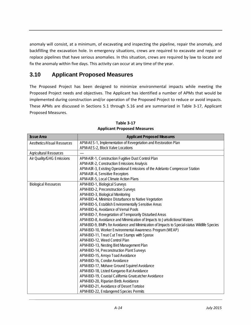
A-14 July 2015
anomaly will consist, at a minimum, of excavating and inspecting the pipeline, repair the anomaly, and backfilling the excavation hole. In emergency situations, crews are required to excavate and repair or replace pipelines that have serious anomalies. In this situation, crews are required by law to locate and fix the anomaly within five days. This activity can occur at any time of the year.
3.10 Applicant Proposed Measures
The Proposed Project has been designed to minimize environmental impacts while meeting the Proposed Project needs and objectives. The Applicant has identified a number of APMs that would be implemented during construction and/or operation of the Proposed Project to reduce or avoid impacts. These APMs are discussed in Sections 5.1 through 5.16 and are summarized in Table 3-17, Applicant Proposed Measures.
Table 3-17 Applicant Proposed Measures
Issue Area Applicant Proposed Measures Aesthetics/Visual Resources APM-AES-1, Implementation of Revegetation and Restoration Plan
APM-AES-2, Block Valve Locations Agricultural Resources — Air Quality/GHG Emissions APM-AIR-1, Construction Fugitive Dust Control Plan
APM-AIR-2, Construction Emissions Analysis APM-AIR-3, Existing Operational Emissions of the Adelanto Compressor Station APM-AIR-4, Sensitive Receptors APM-AIR-5, Local Climate Action Plans
Biological Resources APM-BIO-1, Biological Surveys APM-BIO-2, Preconstruction Surveys APM-BIO-3, Biological Monitoring APM-BIO-4, Minimize Disturbance to Native Vegetation APM-BIO-5, Establish Environmentally Sensitive Areas APM-BIO-6, Avoidance of Vernal Pools APM-BIO-7, Revegetation of Temporarily Disturbed Areas APM-BIO-8, Avoidance and Minimization of Impacts to Jurisdictional Waters APM-BIO-9, BMPs for Avoidance and Minimization of Impacts to Special-status Wildlife Species APM-BIO-10, Worker Environmental Awareness Program (WEAP) APM-BIO-11, Treat Cut Tree Stumps with Sporax APM-BIO-12, Weed Control Plan APM-BIO-13, Nesting Bird Management Plan APM-BIO-14, Preconstruction Plant Surveys APM-BIO-15, Arroyo Toad Avoidance APM-BIO-16, Condor Avoidance APM-BIO-17, Mohave Ground Squirrel Avoidance APM-BIO-18, Listed Kangaroo Rat Avoidance APM-BIO-19, Coastal California Gnatcatcher Avoidance APM-BIO-20, Riparian Birds Avoidance APM-BIO-21, Avoidance of Desert Tortoise APM-BIO-22, Endangered Species Permits

A-15 July 2015
Table 3-17 Applicant Proposed Measures
Issue Area Applicant Proposed Measures APM-BIO-23, Avoidance of Special-Status Plants APM-BIO-24, Burrowing Owl Avoidance and Mitigation APM-BIO-25, Raptor Nest Avoidance APM-BIO-26, Avoidance of Other Special-status Wildlife APM-BIO-27, Compensation for Sensitive Vegetation Communities, Habitat, and Plants APM-BIO-29, Urban/Wildlands Interface Guidelines APM-BIO-30, Consistency with Habitat Conservation Plans
Cultural Resources APM-CUL-1, Coordination with Native Americans tribes and individuals APM-CUL-2, Consultation with local historical societies and other repositories of information regarding cultural resources of the historical period APM-CUL-3, Cultural Resources Survey APM-CUL-4, Evaluation of Identified Cultural Resources APM-CUL-5, Access Effects of the Project on Historical Resources APM-CUL-6, Treatment Plan of Historical Resources APM-CUL-7, Unanticipated Discovery Plan for Cultural Resources APM-CUL-8, Treatment of Human Remains APM-CUL-9, Paleontological Literature Review and Records Search APM-CUL-10, Paleontological Mitigation Plan
Geology, Soils, and Seismicity APM-GEO-1, Geotechnical Investigation APM-GEO-2, Determination of active or potentially active faults APM-GEO-3, Appropriate design ground motion values APM-GEO-4. Appropriate design features to prevent or limit liquefaction APM-GEO-5, Appropriate design features to prevent or limit landslide/slop instability APM-GEO-6, Soil Erosion or Loss of Topsoil APM-GEO-7, Appropriate design features to prevent or limit damage to the pipeline and appurtenant structures on unstable geologic unit or soil APM-GEO-8, Appropriate design and construction recommendations to prevent or limit expansive material damage to the pipeline and appurtenant structures
Hazards and Hazardous Materials
APM-HAZ-1, Project-Specific Hazardous Materials Management and Hazardous Waste Management Program APM-HAZ-2, Proper Handling for the Transport of Hazardous Materials APM-HAZ-3, Procedures for Fueling and Maintenance of Construction Equipment APM-HAZ-4, Emergency Response Plan APM-HAZ-5, Containment and Disposal of HDD Drilling Waste APM-HAZ-6, Spill Prevention, Countermeasure, and Control Plan and Hazardous Materials Business Plan APM-HAZ-7, Hazardous Materials Contingency Plan APM-HAZ-8, Construction Management Plan APM-HAZ-9, Safety and Reliability Study APM-HAZ-10, Emergency Response Plan APM-HAZ-11, Additional Hazardous Materials Research APM-HAZ-12, Fire Protection Plan
Hydrology and Water Quality APM-HYDRO-1, Construction SWPPP APM-HYDRO-2, Equipment Maintenance and Refueling Near Sensitive Areas APM-HYDRO-3, Consultation with the RWQCB to determine if an individual discharge permit is required for dewatering

A-16 July 2015
Table 3-17 Applicant Proposed Measures
Issue Area Applicant Proposed Measures APM-HYDRO-4, Frac-Out Contingency Plan APM-HYDRO-5, Water Reuse Plan
Land Use and Planning — Mineral Resources — Noise APM-NOI-1, Noise Mitigation and Monitoring Plan – Adelanto Compressor Station Operation
APM-NOI-2a, Construction Noise Mitigation Plan APM-NOI-2b, Notification Prior to Construction APM-NOI-3, Noise Mitigation and Monitoring Plan – Pipeline Operation
Population and Housing — Public Services — Recreation — Transportation and Traffic APM-TRF-1, Construction Traffic Control Plan Utilities and Services Systems —
3.11 References
49 CFR 192. Rules and regulations of the U.S. Department of Transportation for natural gas pipelines.
API 1104. Standard for Welding Pipe Lines and Related Facilities

Proponent’s Environmental Assessment North–South Project Page 10-1