Project AVU
119
INTRODUCTION ATMOSPHERIC AND VACUUM UNIT (AVU):- The ADU (Atmospheric Distillation Unit) separates most of the lighter end products such as gas, gasoline, naphtha, kerosene, and gas oil from the crude oil. The bottoms of the ADU is then sent to the VDU (Vacuum Distillation Unit). Crude oil is preheated by the bottoms feed exchanger, further preheated and partially vaporized in the feed furnace and then passed into the atmospheric tower where it is separated into off gas, gasoline, naphtha, kerosene, gas oil and bottoms. Atmospheric and Vacuum unit (AVU) of Mathura Refinery is designed to process 100% Bombay High Crude and 100% Arab Mix crude (consisting of Light and Heavy crude in 50:50 proportion by weight) in blocked out operation @ 11.0 MMTPA. CRUDE DISTILLATION UNIT : The column is provided with 56 trays of which 8 are baffle trays in the stripping section. Heated and partly vaporized crude feed coming from fired heater enters the flash zone of the column at tray no. 46 at 355 ºC/365 ºC. Hydrocarbon vapours flash in this zone and get liberated. Non-flashed liquid moves down which is largely bottom product, called RCO. MP steam having some degree of superheat is introduced in the column below tray no. 46 at approximately 3.5 kg/cm 2 (g) and 290 ºC for stripping of RCO. Steam stripping helps 1
-
Upload
sumit-kaushik -
Category
Documents
-
view
247 -
download
3
description
project
Transcript of Project AVU

INTRODUCTION
ATMOSPHERIC AND VACUUM UNIT (AVU):-
The ADU (Atmospheric Distillation Unit) separates most of the lighter end products such as gas, gasoline, naphtha, kerosene, and gas oil from the crude oil. The bottoms of the ADU is then sent to the VDU (Vacuum Distillation Unit).
Crude oil is preheated by the bottoms feed exchanger, further preheated and partially vaporized in the feed furnace and then passed into the atmospheric tower where it is separated into off gas, gasoline, naphtha, kerosene, gas oil and bottoms.
Atmospheric and Vacuum unit (AVU) of Mathura Refinery is designed to process 100% Bombay High Crude and 100% Arab Mix crude (consisting of Light and Heavy crude in 50:50 proportion by weight) in blocked out operation @ 11.0 MMTPA.
CRUDE DISTILLATION UNIT :
The column is provided with 56 trays of which 8 are baffle trays in the stripping section. Heated and partly vaporized crude feed coming from fired heater enters the flash zone of the column at tray no. 46 at 355 ºC/365 ºC. Hydrocarbon vapours flash in this zone and get liberated. Non-flashed liquid moves down which is largely bottom product, called RCO.
MP steam having some degree of superheat is introduced in the column below tray no. 46 at approximately 3.5 kg/cm2 (g) and 290 ºC for stripping of RCO. Steam stripping helps to remove lighter constituents from the bottom product (RCO). Hydrocarbon vapours liberated by flashing moves up along with the steam in the column for further mass transfer at trays in the upper section.
Reduced crude oil product is collected at the bottom of the column and the overhead vapours are totally condensed in Overhead air Condenser and train condenser. This condensed overhead product is separated as hydrocarbon and water in the reflux drum. Water is drawn out under inter-phase level control and sent to sour water drums.
1

CDU
CRUDE RECEIVING
CRUDE PREHEATING (FIRST STAGE)
DESALTING OF CRUDE
CRUDE PREHEATING (SECOND STAGE)
PREFRACTIONATOR DISTILLATION
CRUDE PREHEATING (THIRD STAGE)
RAISING TEMPERATURE WITH FIRED HEATERS
ATOMOSPHERIC DISTILLATION
NAPHTHA STABILISATION
PRODUCT ROUTING AFTER HEAT RECOVERY
TYPES OF CRUDE:
Low Sulphur
Indian: Bombay High
Nigerian: Girasol, Escravos ,Farcados, Bonny ligh
High Sulphur
Imported: Arab Mix, Kuwait, Dubai, Ratawi, Basra etc
1.1 UNIT SECTIONS & CAPACITIES :
UNIT CAPACITYCrude Distillation Unit 6.00 MMTPA
Vacuum Distillation Unit. 3.30 MMTPANaphtha stabiliser. 1.22 MMTPA Naphtha splitter. 1.10 MMTPA
MTO splitter. 0.03 MMTPANaphtha caustic wash C5-90ºC cut 90-120º cut
0.37 MMTP 0.48 MMTPA
LPG vaporiser 5.0 Tons Hrs.
2

1.1.1 STREAM FACTOR :
Numbers of stream days per year are 345 days (8000 Hrs./year) for Crude distillation and Vacuum distillation sections.
1.1.2 TURN-DOWN RATIO :
UNIT CASE TURNDOWN RATIOCDU HS Crude 50% of 6.0 MMTPA
LS Crude 50% of 6.0 MMTPAVDU with NSU heater operation 50% of 3.2496 MMTPA
of RCO (AM case)without NSU heater operation 50% of 3.2496 MMTPA
of RCO (AM case)FO firing, max., slop recycle & NSU
heater also operating80%
FG firing with max. slop recycle & NSU heater also operating.
60%
FG + FO Firing with max. slop recycle & recycle NSU heater also operating.
70%
FG + FO firing with max. & NSU heater not operating.
60%
NSU FO firing. Max. reflux & AM C5-90 overhead product with VDU heater also
operating.
75%
FG firing, max. reflux & AM C5-90 overhead product with VDU heater also
operating
55%
FG + FO firing max. reflux & AM C5-90 overhead product with VDU heater also
operating.
65%
FG + FO firing, with or without VDU heater in operation.
50%
MTO --- 50%
3

1.2 PRODUCTS EX CDU/VDU MAIN COLUMNS:
S.NO SHORT
NAME
LONG NAME CUT RANGE º C
USAGE
1.GAS
Fuel gas C1-C2 Internal fuel
2. LPG Liquefied Petroleum Gas
C3-C4 Domestic fuel Gas
3. NAP Naphtha C5-120MS Component
4. HN Heavy Naphtha C5-120 HSD Component5. KERO Kerosene 140-270 Domestic fuel6. ATF Aviation Turbine
Fuel140-240 Airplanes
7. LGO Light Gas Oil 240/270-320 HSD Component8. HGO Heavy Gas Oil 320-370 HSD Component9. VD Vacuum Diesel 370 HSD Component
10. LVGO Light Vacuum gas Oil
370-425 Feed to HCU/FCCU
11. HVGO Heavy Vacuum Gas Oil
425-550 Feed to HCU/FCCU
12. V.SLOP Vacuum Slop 550-560 IFO Component/ feed to RFCCU
13. VR Vacuum Residue 560+ Bitumen/ VBU feed
1.3 CRUDE SPECIFICATIONS:
S.NO PROPERTY RANGE1 Gravity 30-40 º C API2 Viscosity 3-24 Cst @ 36 º C3 Pour point (-) 30 – (+) 30 º C4 RVP 0.34-0.67 Kg/cm2 (max.)5 Salt content 165 ppm (max.)6 BS & W 2.0% vol. (max.)7 Total Sulphur 0.17-2.35 % Wt.8 Wax Content 10.68-2.8% wt.
4

1.4 MATERIAL BALANCE (DESIGN):
BH CRUDE ARAB MIX CRUDESK-RUN ATF-RUN
MT/HR WT% MT/HR WT% A) CDUCRUDE 750 100 750 100
GAS 1.81 0.24 - -LPG 14.5 1.93 9.6 1.28
NAPHTHA 102.43 13.66 63.9 8.52HY.NAPH. 33.75 4.5 19.49 2.6
KERO 192.75 25.7 113.25 15.1LGO 80.29 10.7 81.71 10.9HGO 40.26 5.37 54.47 7.26RCO 283.1 37.75 406.2 54.16LOSS 1.11 0.15 1.38 0.18
1.6 LIST OF EQUIPMENTS:
A) COLUMNS:
S.NO. EQUIPMENT NUMBER DESCRIPTION1. 03-C-001 Crude Distillation column2. 03-C-002 Heavy Naphtha stripper3. 03-C-003 KERO/ATF Stripper4. 03-C-004 LGO stripper5. 03-C-005 HGO stripper6. 03-C-006 Naphtha stabiliser7. 03-C-007 Naphtha splitter8. 03-C-008 MTO Splitter9. 04-C-001 Vacuum Distillation column
10. 19-C-001 LPG Amine Absorber11. 19-C-002 Fuel Gas Amine Absorber
5

B) VESSELS :
S.NO. EQUIPMENT
NUMBER
DESCRIPTION
1. 03-V-001 Crude Preflash vessel.2. 03-V-002 Crude column o/h reflux drum.3. 03-V-003 Stabiliser reflux drum4. 03-V-004 Naphtha splitter o/h reflux drum.5. 03-V-005 MTO splitter reflux drum.6. 03-V-006 CDU Furnace Decoking pot7. 03-V-007 A/B Caustic soln.tk. for pre & post-desalter
caustic dosing8. 03-V-008 Corrosion inhibitor drum9. 03-V-009 Demulsifier drum.
10. 03-V-010 Caustic solution tank (mother tank)11. 03-V-011 Ammonia solution vessel12. 03-V-013 Desalter water drum13. 03-V-014 Tempered water drum. 14. 03-V-015 Naphtha caustic wash vessel. (C5-90 º C
cut)15. 03-V-016 Naphtha water wash vessel (C5-90 º C
cut)16. 03-V-017 Spent caustic drum17. 03-V-018 Naphtha caustic wash vessel. (90-120 º
C cut)18. 03-V-019 Naphtha caustic wash vessel. (90-120 º
C cut)19. 03-V-020 Sour water quench drum. (from 03-V-5)20. 03-V-021 CBD drum.21. 03-V-022 Flare knock out drum22. 03-V-023 MP steam drum.23. 03-V-024 LP steam drum.24. 03-V-025 Steam blow down drum.25. 03-V-026 LPG vaporiser drum.26. 03-V-027 Fuel gas knock out drum27. 03-V-032 TSP vessel.28. 03-V-033 Flushing oil vessel.(CDU)29. 04-V-001 Hot well.30. 04-V-002 Water coalescer.31. 04-V-003 Hot well catch pot.32. 04-V-004 VDU Furnace Decoking pot.33. 04-V-12 Vacuum Slop quench drum.34. 04-V-13 Flushing oil vessel.(VDU)
6

35. 19-V-001 Sour fuel gas filter separator.36. 19-V-002 Sweet gas filter separator.37. 19-V-003 Amine sump.38. 19-V-004 LPG surge drum.39. 19-V-005 Anti foam agent drum.40. 19-V-201 Ist stage caustic wash vessel.41. 19-V-202 2nd stage caustic wash vessel.42. 19-V-203 Ist stage LPG/ caustic mixer.43. 19-V-204 2nd stage LPG/ caustic mixer
C) PUMPS :
S.NO. EQUIPMENT NUMBER DESCRIPTION1. 03-P-01A/B/C Crude charge pump.2. 03-P-02A/B/C Preflashed crude pumps.3. 03-P-03A/B/C Desalted crude pumps. (not in use). 03-
P-3A converted to fire water booster pump.
4. 03-P-04A/B Stabiliser feed pumps.5. 03-P-05A/B Atm. Column top reflux pumps.6. 03-P-06A/B/C HN circulating reflux pumps.7. 03-P-07A/B/C Kero/ATF circulating reflux pumps.8. 03-P-08A/B/C LGO circulating reflux pumps.9. 03-P-09A/B/C HGO circulating reflux pumps.
10. 03-P-10A/B Hy. Naphtha product pumps11. 03-P-11A/B Kero/ATF product pumps.12. 03-P-12A/B LGO product pumps.13. 03-P-13A/B HGO product pumps14. 03-P-14A/B/C Reduced crude oil pumps.15. 03-P-15A/B Naphtha stabiliser reflux/LPG product
pumps.16. 03-P-16A/B Naphtha splitter reflux/overhead product
pumps.17. 03-P-17A/B MTO splitter reflux/overhead product
pumps18. 03-P-19A/B MTO splitter bottom product pumps19. 03-P-20A/B/C Naphtha splitter bottom/Furnace feed
pumps.20. 03-P-21A/B 2nd stage desalter water pumps21. 03-P-22A/B 1st stage desalter water pumps22. 03-P-24A/B Naphtha Caustic circulation pumps. (c5-
90)23. 03-P-25 Naphtha Water circulation pumps. . (c5-
90)
7

24. 03-P-26A/B Spent caustic pumps.25. 03-P-27A/B Naphtha Caustic circulation pumps. (90-
120)26. 03-P-28 Naphtha Water circulation pumps. (90-
120)27. 03-P-29A Water make up pumps.28. 03-P-30A/B MTO product pumps.29. 03-P-35A/B Main tempered water pumps .30. 03-P-36A/B Tempered water pumps31. 03-P-37 Caustic make up pump.32. 03-P-38 CBD pump33. 03-P-41A/B MTO Splitter feed pumps (removed as
not required)34. 03-P-44A/B/C Flushing oil pumps (LGO)35. 03-P-45A/B Atmospheric reflux drum boot sour water
pumps.36. 04-P-01A/B Vac. diesel product+IR+CR pumps.37. 04-P-02A/B LVGO product+IR+CR pumps38. 04-P-03A/B/C HVGO product+IR+CR pumps39. 04-P-04A/B/C Slop + Recycle pumps.40. 04-P-05A/B Vacuum residue + quench pumps. (04-P-
5B removed)41. 04-P-06A/B Vacuum residue + quench pumps.42. 04-P-07A/B Hot well Sour water pumps.43. 04-P-08A/B Hot well Slop oil pumps.44. 04-P-09A/B Flushing oil pumps (HVGO) .45. 03-P-MT-31A/B/C Corrosion inhibitor pumps.46. 03-P-MT-32A/B Demulsifier injection pumps.47. 03-P-MT-33A/B Caustic injection pumps.48. 03-P-MT-34A/B/C Ammonia solution injection pumps.49. 03-P-MT-43A/B TSP dosing pumps.50. 19-P-001A/B Rich Amine transfer pumps.51. 19-P-002A Amine sump pumps.52. 19-P-003A/B Anti foam injection pumps.(removed as
not required)53. 19-P-201A/B LPG caustic circulation pumps.54. 19-P-202 LPG caustic circulation pumps.55. 19-P-203A/B Strong caustic injection pumps from 03-
V-10
8

D) FURNACES :
S.NO. EQUIPMENT NUMBER DESCRIPTION.1. 03-F-001 Crude Furnace2. 03-F-002 Naphtha splitter furnace3. 04-F-001 Vacuum Furnace
E) EJECTORS :
S.NO. EQUIPMENT NUMBER DESCRIPTION.1. 04-EJ-001A/B/C 1st stage ejector2. 04-EJ-002A/B/C 2nd stage ejector3. 04-EJ-003A/B/C 3rd stage ejector
F) AIR FIN COOLERS :
S.NO. EQUIPMENT
NUMBER
DESCRIPTION.
1. 03-EA-LP-001 A-P Crude column o/h air cooler2. 03-EA-LP-002 A-H Naphtha splitter o/h air cooler3. 03-EA-LP-003 LGO product Air cooler4. 03-EA-LP-004 HGO product Air cooler5. 03-EA-LP-005 HN product Air cooler6. 03-EA-LP-006 Kero/ATF product cooler7. 03-EA-LP-007 Naphtha splitter bottom air cooler8. 03-EA-LP-008 MTO product Air cooler9. 03-EA-LP-009 A-D Main Tempered water air cooler.
10. 03-EA-LP-010 A-B Tempered water air cooler.11. 03-EA-LP-011 Naphtha stabiliser air cooler12. 04-EA-LP-001 A-B Vacuum diesel air cooler.
G) AIR FIN COOLER FANS :
S.NO. EQUIPMENT NUMBER DESCRIPTION.1 03-EA-FN-001 A-P Crude column o/h air cooler-16 nos2 03-EA-FN-002 A-H Naphtha splitter o/h air cooler- 8 nos3 03-EA-FN-003 A-B LGO, HN & Kero/ATF air cooler (EA LP
3,5,6)4 03-EA-FN-004 A-B HGO & MTO Air cooler (EA-LP- 4 & 8)5 03-EA-FN-007 A-B NSU & Stabiliser bottom air cooler (EA
LP 7,11)6 03-EA-FN-009 A-D Main Tempered water air cooler.- 4 nos7 03-EA-FN-010 A-B Tempered water air cooler – 2 nos8 04-EA-FN-001 A-B Vacuum diesel air cooler- 2 nos
9

H) EXCHANGERS :
S.NO. EQUIPMENT NUMBER DESCRIPTION.1. 03-E-001A/B Crude column o/h trim cooler.2. 03-E-002A/B Stabiliser o/h condenser.3. 03-E-004A/B Naphtha splitter o/h product cooler.4. 03-E-007 Hy. Naphtha product trim cooler.5. 03-E-008A/B Kero/ATF product trim cooler6. 03-E-009 LGO product trim cooler7. 03-E-010 HGO product trim cooler8. 03-E-013 Crude/Kero/ATF exchanger.9. 03-E-014A/B Crude/Kero/CR exchanger.
10. 03-E-015 Crude/Vacuum diesel CR exchanger.11. 03-E-016A/B Crude/Hy. Naphtha CR exchanger.12. 03-E-017 Crude/VR exchanger.13. 03-E-018 Crude/HVGO exchanger.14. 03-E-019 Crude/LGO exchanger.15. 03-E-020A/B Crude/Kero/ATF exchanger.16. 03-E-021 Crude/Kero/ATF exchanger17. 03-E-022 Crude/LGO CR exchanger18. 03-E-023 Crude/HGO exchanger.19. 03-E-024A/B Crude/LVGO exchanger.20. 03-E-025 Crude/HVGO exchanger.21. 03-E-026A/B Crude/LGO exchanger.22. 03-E-027A/B Crude/LVGO exchanger.23. 03-E-028A/B/C/D/E Crude/VR exchanger.24. 03-E-029 Crude/slop exchanger.25. 03-E-030A/B/C Crude/LGO CR exchanger26. 03-E-031 Crude/HGO exchanger.27. 03-E-032 Crude/HGO CR exchanger.28. 03-E-033A/B Crude/HVGO CR exchanger.29. 03-E-034A/B Crude/HVGO exchanger.30. 03-E-035 Crude/HGO exchanger.31. 03-E-036 Crude/HVGO CR exchanger.32. 03-E-040 Tempered water/HGO exchanger.33. 03-E-041 Tempered water/LGO exchanger.34. 03-E-042 Naphtha splitter bottom trim cooler.35. 03-E-043A/B/C Tempered water/DM water exchanger36. 03-E-044 MTO splitter o/h condenser.37. 03-E-046A/B Desalter water/brine exchanger.38. 03-E-047 MTO product trim cooler.39. 03-E-048 MTO bottom product trim cooler.40. 03-E-050 MTO o/h trim cooler.41. 03-E-051A/B/C MTO splitter feed/bottom exchanger.
10

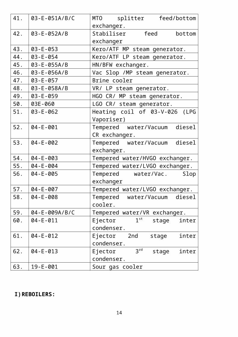
42. 03-E-052A/B Stabiliser feed bottom exchanger43. 03-E-053 Kero/ATF MP steam generator.44. 03-E-054 Kero/ATF LP steam generator.45. 03-E-055A/B HN/BFW exchanger.46. 03-E-056A/B Vac Slop /MP steam generator.47. 03-E-057 Brine cooler48. 03-E-058A/B VR/ LP steam generator.49. 03-E-059 HGO CR/ MP steam generator.50. 03E-060 LGO CR/ steam generator.51. 03-E-062 Heating coil of 03-V-026 (LPG Vaporiser)52. 04-E-001 Tempered water/Vacuum diesel CR
exchanger.53. 04-E-002 Tempered water/Vacuum diesel
exchanger.54. 04-E-003 Tempered water/HVGO exchanger.55. 04-E-004 Tempered water/LVGO exchanger.56. 04-E-005 Tempered water/Vac. Slop exchanger57. 04-E-007 Tempered water/LVGO exchanger.58. 04-E-008 Tempered water/Vacuum diesel cooler.59. 04-E-009A/B/C Tempered water/VR exchanger.60. 04-E-011 Ejector 1st stage inter condenser.61. 04-E-012 Ejector 2nd stage inter condenser.62. 04-E-013 Ejector 3rd stage inter condenser.63. 19-E-001 Sour gas cooler
I) REBOILERS:
S.NO. EQUIPMENT NUMBER DESCRIPTION.
1. 03-E-BU-03A/B Stabiliser reboiler 2. 03-E-BU-006 MTO splitter reboiler.3. 03-E-BU-011 HN reboiler4. 03-E-BU-012A/B Kero/ATF reboiler.
J) DESALTERS:
S.NO. EQUIPMENT NUMBER DESCRIPTION.1. 03-LD-001 Crude Desalter 1st stage2. 03-LD-002 Crude Desalter 2nd stage
11

K)MISCELLANEOUS:
S.NO. EQUIPMENT NUMBER DESCRIPTION.1. 19-GN-201 LPG Sand filter2. SP-1201 Hydrocarbon skim off vessel3. 03 F AP 002 A/B &
006 A/BCast APH & Glass APH for 03-F-001
4. 04 F AP 002 & 006 Cast APH & Glass APH for 04-F-001/03-F-002
5. 03-FF-FN-003 A/B FD fan for 03-F-0016. 03-FF-FN-004 ID fan for 03-F-0017. 04-FF-FN-003 A/B FD fan for 04-F-001/03-F-0028. 04-FF-FN-004 ID fan 04-F-002/03-F-002.9. 03-FF-ST-005 AVU stack
10. 03-JS-001 Silencer (MP Steam Drum)11. 03-JS-002 Silencer (LMP Steam Drum)12. 03-JS-003 Silencer (LP Steam Drum)13. 03-VM-001 Mixer Corrosion Inhibitor14. 03-VM-002 Mixer-Demulsifier15. 03-VM-004 Mixer-TSP16. 04-GN-001 Vacuum diesel CR filter17. 04-GN-002 Vacuum diesel IR filter18. 04-GN-003 LVGO-CR filter19. 04-GN-004 HVGO CR+LVGO IR filter20. 04-GN-005 HVGO IR FILTER21. 03-GN-001 MTO Clay Filter
12

PROCESS DESCRIPTION
2.1 FEED SUPPLYCrude oil is stored in eight nos. storage tanks i.e. TK-301 to 308 located in offsite area, each tank having a nominal capacity of 50,000 KL. Booster pumps (45-P-001A/B/C) located in offsite area are taking suction from one of these tanks and delivering crude to suction of unit feed pumps 03-P-001A/B/C.
2.1.1 SLOP PROCESSINGProvision to reprocess 5% of slops with crude exists in the unit. Slop oil ex slop tanks (2001,2002,2003) through 03-FV-1101 is injected in crude inlet line at battery limit. The slop oil is transferred from offsite to unit by pump No. 47-P-A/B.
2.2 1st PREHEAT TRAIN Crude oil from crude charge pumps (03-P-001A/B/C) is charged to preheat exchanger trains in two parallel streams. Total crude flow unit is recorded by flow meter 03-FT-1102 & divided into two streams with the help of 03-FRC-1104 and 03-HIC-1101. Provision has been kept to inject caustic and demulsifier solution at suction of crude charge pumps. The impellers of crude charge pumps 03-P-1 A/B/C have been trimmed from it’s original impeller dia of 404 mm to 380 mm to reduce power consumption as well as for better pressure control of desalter.
2.2.1 CRUDE-EX 03-FRC-1104. (1st PREHEAT TRAIN)
The first crude stream passes through 03-E-015 (Crude v/s vacuum diesel CR) and picks up heat from Vacuum Diesel CR coming at 142-166º c. Vacuum Diesel CR is cooled to 91-99º C, whereas crude is getting heated upto 56-61º C.Crude outlet from 03-E-015 enters 03-E-016A/B (Crude v/s Hy. Naphtha CR) exchanger. Crude gets heated upto 87-103º C whereas Hy. Naphtha CR gets cooled from 122-147º C to 94-108º C.
13
14

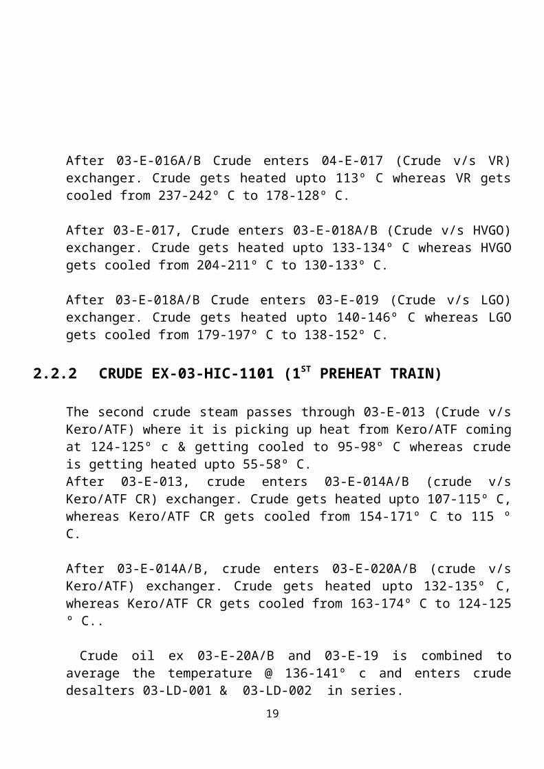
After 03-E-016A/B Crude enters 04-E-017 (Crude v/s VR) exchanger. Crude gets heated upto 113º C whereas VR gets cooled from 237-242º C to 178-128º C.
After 03-E-017, Crude enters 03-E-018A/B (Crude v/s HVGO) exchanger. Crude gets heated upto 133-134º C whereas HVGO gets cooled from 204-211º C to 130-133º C.
After 03-E-018A/B Crude enters 03-E-019 (Crude v/s LGO) exchanger. Crude gets heated upto 140-146º C whereas LGO gets cooled from 179-197º C to 138-152º C.
2.2.2 CRUDE EX-03-HIC-1101 (1ST PREHEAT TRAIN)
The second crude steam passes through 03-E-013 (Crude v/s Kero/ATF) where it is picking up heat from Kero/ATF coming at 124-125º c & getting cooled to 95-98º C whereas crude is getting heated upto 55-58º C.After 03-E-013, crude enters 03-E-014A/B (crude v/s Kero/ATF CR) exchanger. Crude gets heated upto 107-115º C, whereas Kero/ATF CR gets cooled from 154-171º C to 115 º C.
After 03-E-014A/B, crude enters 03-E-020A/B (crude v/s Kero/ATF) exchanger. Crude gets heated upto 132-135º C, whereas Kero/ATF CR gets cooled from 163-174º C to 124-125 º C..
Crude oil ex 03-E-20A/B and 03-E-19 is combined to average the temperature @ 136-141º c and enters crude desalters 03-LD-001 & 03-LD-002 in series.
Provision has been kept to inject wash water and demulsifier ahead of 03-DPC 201 i.e. mixing valve at inlet of Desalter-1 & ahead of 03-DPC-1202 i.e. mixing valve at inlet of Desalter-2.
2.3 ELECTRIC DESALTERS:
2.3.1 GENERAL DISCUSSION ON PROCESS :
The desalter is an electrostatic coalescer used for purification of crude from sludge, salts and corrosion inducing salts. Sludge and salts like NaCl generally gets deposited on the tubes of exchangers and thus reduce preheat temperature. Salt if not removed will cause corrosion in distillation column. There is no relationship between salt and sediment content in the crude oil except each might increase with increase in water content in crude oil. Sediment contains fine particles of sand, clay, mud, rust etc. Salts may vary
15

widely in the ratio of metal ions and brine concentration though 75% Na, 15% Mg and 10% Ca are common averages. Chloride is the source of the indices of corrosion potential of the crude. MgCl2 is the most specific producer of HCI with Ca and Na in descending order. Apart from chloride, carbonates may be present in significant quantities, sulfates may be troublesome and cause sulfate scale formation.
These water-soluble impurities are brought along with the residual water content into the crude oil. Much of the sediment also may be associated with this dispersion of water. Water drops ordinarily are so small that gravity would require a prohibitively long time to draw all of the drops to the bottom of a storage tank, even if the tank were free from convection currents. Moreover this water dispersion, or in other words, the emulsion received at the Refinery has been ‘aged’ over an extended period by stabiliser. These stabiliser are molecules or groups of molecules, asphalts, etc. in the oil that are least similar to the bulk oil (i.e. least similar to the most prevalent oil molecular species), and therefore subject to less intermolecular force. Being less attracted to the internal body of the oil, the exceptional material will be rejected to the interface of the oil water drops. Such rejected surface active materials comprise a physical barrier that prevents water drops getting close enough to bring about coalescence. Before the drops can coalesce, therefore the stabiliser film must be reduced in thickness and tenacity, and ruptured. An effective means for aiding this is heat. Heat increases the solvency of the bulk oil for the stabiliser, reduces the viscosity of the oil and decreases the cohesion of the film. These effect though very much beneficial are normally not adequate to permit coalescence.
The limitation of distance between drops is dealt with by dispersing about 5% of fresh water to the oil. Thus the water has been increased about 25 times and the distance between drops surfaces reduced by 10. Even so, the added water is not likely to combine with a satisfactory portion of the brine particles and coalesce effectively without additional means.
In desalting, the electric field is a powerful tool for overcoming the resistance of stabilising films. The collision and coalescence of drops is accomplished by an induced dipole attraction between them. That is the electrical charges inherent in each droplet are separated so that positive charges move to one end of the droplet and negative charges move to the other end.
As droplets then approach each other, the force between them becomes very great. The stabilizing films are squeezed between drops and coalescence is rapid. In a 5% emulsion, drops average about two diameters apart; coalescence proceeds almost instantaneously. The distance between drops then increases as drops fall due to gravity. For a 1% emulsion, drops are four diameters apart and coalescence slows. When the emulsion content is 0.1%, drops are eight diameters apart on the average. The forces of dipole
16

attraction, diminished by a factor of 250, are insignificant at this distance and the final emulsion content shall depend on this to about 0.1%.
2.3.2 SYSTEM DESCRIPTION :
It may be seen from the above discussion that the process of desalting consists of three main stages viz. heating, mixing & separation.
Crude oil is heated up to 136-141º C in the train of Heat Exchangers operating in two parallel sections. Desalting temperature as required can be maintained manually by operating the bypass valve of Heat Exchangers.
A two-stage bielectric desalter (03-LD-001/002) has been designed for 99% salt removal with an outlet salt PPM of <0.1% wt. at outlet. It is designed to use stripped sour water for desalting which is being taken ex stripped sour water unit. Provision to use DM water/Service water is also provided. The level in the desalter water vessel 03-V-013 is maintained by 03-LIC-1207. 2nd stage desalting pumps 03-P-021A/B are used for injecting stripped water into crude line upstream of 2nd stage mixing valve 03-DPIC-1202 under flow control after heating it with not brine from the 1st stage desalter in 03-E-046A/B. The 2nd
stage aqueous phase is transferred to 1st stage desalter by pumps 03-P-022-A/B under interface level control.
Selector switch SS-1201/1204/1205/1206 is provided to operate each desalter independently. Pressure in the desalter is maintained by 03-PIC-1201 at the inlet of first preheat train provided at the discharge of crude charge pump 03-P-1 A/B/C. The electric field in the desalter breaks the emulsion and the outlet brine from the 1st stage desalter is sent to ETP on level control. 03-LIC-1201/1204 after cooling in 03-E-046 (Brine v/s desalter water)) and 03-E-057 (CW v/s Brine).
For physical checking of aqueous and oil levels try lines are provided at different heights in the lower half of the desalters.
The desalter vessels are protected from over pressure by safety valves which release excess pressure to crude column 03-C-001 flash zone. The safety valves are located close to the column. Desalters drain is connected to both CBD & OWS. As per original scheme, crude outlet of desalter 03-LD-002 was going to desalted crude pumps 03-P-003A/B/C and further to pre-flash drum (03-V-1) through 2nd preheats train. Presently crude is going to 03-V-1 bypassing 03-P-3 pumps at the desalter pressure. A separate bypass line has been provided for the above.
17

18
2.4 2ND PREHEAT TRAIN :
Crude from second desalter, bypassing crude pump (03-P—003 A/B/C) discharge, is divided into parallel heat exchanger trains by HIC-1301 and FRC-1302.
Provision has been kept to inject caustic at second desalter outlet. However, caustic injection at Post Desalter should preferably be avoided due to unreacted caustic carryover to Heat Exchangers, furnaces, FCCU, OHCU, etc.
2.4.1 CRUDE EX-03-FRC-1302 (2ND PREHEAT TRAIN) :
The first desalted Crude stream passes through 03-E-023 (Crude v/s HGO) where it is picking up heat from HGO coming at 185-194º C and getting cooled to 140-144º C whereas crude is getting heated up to 140-142º C.
After 03-E-023, crude enters 03-E-024 A/B (Crude v/s LVGO) exchanger. Crude gets heated up to 166-174º C whereas LVGO gets cooled from 265-268º C to 147-152º C.
After 03-E-024A/B crude enters 03-E-031 (Crude v/s HGO) exchanger. Crude gets heated up to 185-194 º C.
2.4.2 CRUDE EX-03-HIC-1301 (2ND PREHEAT TRAIN) :
The second desalted crude stream passes through 03-E-021 (Crude v/s Kero/ATF) where it is picking up heat from Kero/ATF coming at 195-205º c and getting cooled to 163-174º C whereas crude is getting heated upto 146-153º C.
After 03-E-021, crude enters 03-E-022 (Crude v/s LGO CR) where it is picking up heat from LGO CR coming at 185-190º C and getting cooled to 170-180º C whereas crude is getting heated upto 155-162º C.
After 03-E-022, crude enters 03-E-025 (Crude v/s HVGO) where it is picking up heat from HVGO coming at 248-291º C and getting cooled to 204-211º C whereas crude is getting heated up to 173-176º C.
19

20

2.4.3 CRUDE PRE FLASHING :
Crude oil ex 03-E-025 and 03-E-031 is combined to average the temperature @ 179-180º C and enters pre-flash drum (03-V-1) where 3-4% wt. of light ends are removed. Pre-flash drum pressure is controlled by 03-PIC-1301. The flashed vapor is sent to flash zone of 03-C-001 and also provision is there to route it to Hy. Naphtha section of crude column. Level in the preflash drum is maintained by 03-LIC-1301. Crude after flashing in the preflash drum is pumped by 03-P-002A/B/C through 3rd preheat train.
Interlock I-3 will trip the pump 03-P-002A/B/C by activation of press alarms i.e. PAL-1306/1307/1308 sensed from pump suction. Interlock I-4 will trip 03-P-002A/B/C on LSLL-1301 actuation.As long as there is no advantage of gaining throughput, preflash vapor should be routed to flash zone. Care should be taken on 03-LIC-1301 operation, as its closing will cause over pressurisation of all upstream heat exchangers. To avoid the above situation, a software lock is provided at 20 % so that the LIC does not close beyond 20 % value.
2.5 3rd PREHEAT TRAIN :
Crude discharge 03-P-002 A/B/C is further divided into two parallels preheat circuits by FRC-1402 and HIC-1401.
2.5.1 CRUDE –EX-03-FRC-1402 (3rd PREHEAT TRAIN) :
The first crude stream passes through 03-E-030A/B/C (Crude v/s LGO CR) where it is picking up heat from LGO-CR coming at 241-249º C and getting cooled to 185-190º C whereas crude is getting heated upto 210-213º C.After 03-E-030A/B/C, crude enters 03-E-036 (Crude v/s HVGO CR) exchanger. Crude gets heated up to 218-228º C whereas HVGO CR gets cooled from 259-271º C to 239-258º C.After 03-E-036, crude enters 03-E-032 (Crude v/s HGO CR) exchanger. Crude gets heated up to 223-249º C whereas HGO CR gets cooled from 302-311º C to 275-303º C.After 03-E-032 crude enters 03-E-033A/B (Crude v/s HVGO CR) exchanger. Crude gets heated up to 241-277º C whereas HVGO CR gets cooled from 238-298º C to 239-271º C.After 03-E-033A/B, crude enters 03-E-034A/B (Crude v/s HVGO) exchanger. Crude gets heated up to 251-283º C whereas HVGO gets cooled from 298-306º C to 201-248º C.
21

22

After 03-E-034A/B, crude enters 03-E-035 (Crude v/s HGO) exchanger. Crude gets heated up to 259-289º C whereas HGO gets cooled from 323-325º C to 291-260º C.
2.5.2 CRUDE EX 03-HIC-1401 (3rd PREHEAT TRAIN) :
The second crude stream passes through 03-E-026A/B (Crude v/s LGO) where it is picking up heat from LGO coming at 226-258º C and getting cooled to 179-197º C whereas crude is getting heated up to 184-198º C.After 03-E-026A/B, crude enters 03-E-027A/B (Crude v/s LVGO CR) exchanger. Crude gets heated up to 218-236º C whereas LVGO CR gets cooled from 258-265º C to 204-214º C.After 03-E-027A/B, crude enters 03-E-028A/B/C/D/E (Crude v/s VR) exchanger. Crude gets heated up to 248-265º C whereas VR gets cooled from 350/350º C to 237-242º C.
After 03-E-028A/B/C/D/E, crude enters 03-E-029 (Crude v/s vacuum slop) exchanger. Crude gets heated up to 258-288º C whereas vac slop gets cooled from 353/370º C to 298-353º C.
2.5.3 Crude oil exchanger 03-E-029 and 03-E-035 is combined to average the temperature @ 259-289º C .This temperature is called preheat temperature or coil inlet temperature (CIT) .
2.6 FIRED HEATERS:
The preheated crude is further heated and partially vaporized in Atmospheric Heater 03-F-001 having eight passes. (Four sections with 6 inches sch. 40 tubes).
The atmospheric heater is a box-type vertical furnace with up firing burners, 8 Nos. of burners in each section are provided on the floor with FG and FO firing facilities. Crude flows to each pass is controlled by 03-FIC-1501 to 03-FIC-1508 respectively. A total 32 nos. of burners have been provided in CDU heater. Out of 32 burners, 28 nos. of burners have both FO and FG firing facility and 4 burners, called LP burners have facility to fire off- gas from VDU column and FG (called support burners).
This heater is having two distinct heating sections i.e.
A)RADIANT SECTION: It houses the burners and forms the combustion chamber or fire box. Tubes are arranged in a vertical arrangement along the walls of each cell with tube arrangement itself forming the cell.
23

24

B) COVECTION SECTIONS: It receives heat from hot flue gases leaving the radiant section. Tubes are arranged in horizontal bank and positioned above radiant section.
Preheated Crude oil enters the convection section in eight passes. Temperature indications TI-1502 to 1509 are provided on the outlet of each convection pass. Convection outlet of each pass again enters the Radiation Zone of furnace. The floor of the furnace is elevated above grade and the hot air duct supplying combustion air to burners runs across the length of the furnace.
A return line is provided on fuel oil header to the burners of each furnace to maintain desired circulation flow to avoid dead end of the header and associated problems i.e. difference in pressure availability between extreme end burners, congealing of stagnant portion etc. flow recorders FI-1525, 1528, 1529, are provided respectively on fuel gas, IFO (S) & IFO ® headers to the unit. Shut down valves 03-SDV-1501, 1502, 1503, 1517 are also provided on the main fuel gas, IFO (S) & IFO(R), support burners of LP gas burners respectively. These shutdown valves shall be activated w.r.t trip logic’s provided.
Peep holes are provided on side walls of the furnace to inspect all radiant section tubes. 24 Nos. of soot blowers are provided to keep the convection bank clean. They are operated by automatic control panel located at grade level.
Furnace has total 32 low NOx burners. Each cell has 8 burners along the center line of the cell. One central burner is for combination fuel gas & hot well off gases firing while the balance burners are for combination IFO & FG.
2.6.1 FURNACE FUEL SYSTEM
A)FUEL GAS SYSTEM :Fuel gas system (FG) from fuel gas knock out drum (KOD) 03-V-27, located inside the unit is supplied by a 6” header. The FG line is steam traced to avoid condensation of heavier components inside the line itself and carry over of hydrocarbon liquid droplets to the burner. To arrest carry over of foreign particles like rust etc. a 100-mesh strainer is provided on the line.
FG to main burners passes through a shut down valve SDV-1501 whose open or close position is indicated in control room by XL-1501 A/Xl-1501 B.
25

fuel gas flow/temperature to the main FG burners is indicated in DCS by FI-1525/TI-1510. A local temperature & pressure indicator are provided at the inlet of fuel gas to the main burners. Fuel gas pressure indicator PI-1502, low fuel gas pressure trip alarm PAL-1508 and a very low pressure trip alarm PALL-1509 are provided at the inlet of fuel gas to the main burners. If fuel gas pressure falls below PALL-1509 set value, chances of flame failure in burner, accumulation of unburned FG in fire box and resultant possibility of explosion/back fire through heater openings exists. Actuation of PALL-1509 will shut the SDV-1501 on fuel gas supply to the main burners of the furnace, eliminating this possibility. Minimum stop limit to PV-1501 and all valves on similar duty has also been considered to avoid extinguishing of FG burners on closure of valve due to signal from COT controller TIC-1512.
Fuel gas pressure and hence flow to burners is controlled by PIC-1501. It can be cascaded with crude oil coil temperature (COT) controller TIC-1512. Through a selector switch SS-1512, COT can be used to select either fuel oil or fuel gas as the fuel gas-controlling COT.
A 2” FG tapping upstream of shut down valve SDV-1501 has been taken for pilot burners. On the pilot fuel gas line, PI-1503/FI-1526 are provided to measure FG pressure/flow to pilot burners. Pressure in the pilot gas line is manually adjusted.
A low-pressure alarm PAL-1510 will alert the operator when pilot gas pressure falls. PG-1525/PG-1526 indicates FG pressure in main and pilot gas lines in filed at heater battery limit. 8 Nos. of pilot and 7 Nos. of main FG burner are provided in every cell of the heater.
B) HOT WELL OFF GAS SYSTEM :
Off gases from hot well of VDU are routed to 03-F-001 through hot well Catch pot. After de-entertainment of water/oil droplets in catch pot the off gas pass through strainers of 100 mesh. Hot well off gas pressure atmospheric heater is controlled by PIC-1513, manipulating PV-1513 on off gas vent line to atmosphere. PAL-1514 indicates low off gas pressure to heater. To avoid possibility of back fire due to external spark carryover, flame arrestors AF-1503/AF-1504 & AF-1501/AF-1502 are provided on off gas line to vent as well as heater. Spare flame arrestors are provided to ensure serviceability. Fuel gas pressure control for burners using hot well off gases is done by PIC-1517. Pre trip alarm PAL-1516 and trip alarm PALL-1517 is provided on this header also.
26

C) FO FIRING SYSTEM :
When fuel oil is fired, it is atomized or sprayed as a fine mist for realizing complete combustion. The spraying of FO is done by MP steam in FO burners. Atomizing steam is supplied to heater through a 4” header. Earlier atomising steam was directly supplied to the atomising steam header from the MP steam drum 03-V-23 which was supplying saturated steam. However, to supply atomising steam with higher degree of superheat a jump over has been provided between the decoking steam header (U/S of isolation valve) and the atomising steam header. Atomizing steam pressure is controlled by differential pressure controller DPIC-1501, taking pressure signals form FO supply and MP steam headers simultaneously. It maintains the atomizing steam header pressure. To arrest carry over of foreign particles like rust etc. a 100-mesh strainer is provided on the line.
NOTE: -
When furnace operates on combination fuel, FG operates on PIC-1501 & FO on PIC-1505/TIC-1512 cascade and vice versa. Selector switch SS-1512 is used when only one fuel controls ‘COT’ by cascading.
FUEL AIR CONTROL STRATEGY AT THE FURNACE :
In the combustion control strategy the output signal from coil outlet (03-F-01) TIC-1512 is used for regulating the fuel and air flow rates.
The simultaneous fuel and air controls a cross limit control system. It aims at eliminating the possibility of fuel rich condition in the furnace by ensuring that the fuel demand does not exceed measured air flow and that the air flow does not drop below measured fuel flow. The firing rate demands signal i.e. the TRC-1512 output is sent to two signal selectors.HSS : High signal selector.LSS : Low signal selector.
The HSS compares the TRC output against the operating total fuel flow signal. The higher of these two signals is selected as the SET POINT for air flow controller FIC. (It may be noted that the operating total fuel flow signal to HSS is obtained by adding the conditioned fuel gas flow and the net of fuel oil supply and return flows of that particular furnace. Also a small negative bias is applied to the total fuel flow signal, which permits faster response to load changes within the limit of bias).
27

The HSS causes the air to lead the fuel while increasing the firing and causes the air to lag the fuel while decreasing the firing. The air flow signal sent to the air flow FIC as the MEASURED VARIABLE. is derived from the air flow transmitter and corrected by a multiplication factor. (The multiplication factor is determined by the output of the oxygen controller, the output being filtered, as a precaution, to a narrow range of typical 0.8 to 1.2). The output of air flow FIC sent to operate the control dampers on the hot air ducts of the respective furnace.
The LSS compares the output signal of COT TRC with the corrected air flow signal mentioned above. The normal function of the LSS is to cause the fuel to lag the air while increasing the firing and cause the fuel to lead the air while decreasing the firing. The lower of the signals to LSS is chosen as the SET POINT for fuel flow controller FIC. ( A small positive bias is applied to the ‘corrected’ air flow signal to LSS. This permits faster response to load changes within the limit of bias). The output of fuel controller FIC would then regulate the flow of IFO or fuel gas depending on the mode selected from panel.
2.7 AIR PRE-HEATER SECTION :
To recover the waste heat from fuel gases, two sets of cast and glass air preheaters in parallel are provided along with two forced draft fans for air and one induced draft fan for flue gases.An air bypass damper to bypass APH is provided for bypassing the combustion air, either partly or fully. The combustion air requirement of each heater controlled by individual FIC controller through control damper located in the air duct,
The loads on the FD fans are varied by loading the fans by hydraulic coupling system by manipulating the scoop by changing the instrument air pressure. In case of ID fan, a pressure controller 03-PIC-1534 measures and controls the draft in the main fuel gas duct from the furnace by actuating a pneumatic loader similar to the FD fans.
28

29

2.8 SAFETY TRIPS & INTER LOCKS (GENERAL) :
S.NO.
ACTIVATING CONDITION
TRIPS/INTER LOCKS.
1. Low Off-Gas Pressure OFF-GAS to be cut off2. Low Fuel Oil Pressure Fuel oil to be cut off3. Low Fuel Gas Pressure Fuel Gas to be cut off4. Low flow of feed to
passesFO/FG to be cut off
5. Combustion air low flow FO/FG to be cut off6. Combustion air low
pressureFO/FG to be cut off
7. Failure of ID fan HV will open with 20 secondsIf HV fails to open, FO/FG to be cut off
8. ID fan suction high temp. -Do-9. High temp at glass APH
inlet-Do-
10. Both FD’s fail FO/FG to be cut off11. High Arch pressure HV to open within 10 seconds.
If PAH persists for 20 seconds FO/FG to be cut off within 30 seconds.
12. Fuel failure 1. HV to open fully2. ID fan shall trip3. FD fan shall trip
13. ID fan not in line Damper HV will not be closed.
NOTE: -
All solenoid valves have reset facility available at main control panel. Emergency push buttons has been provided on main control panel pressing
which fuel to the furnace will trip, all drives will trip and damper will open. An additional emergency push button has been located near naphtha
stabiliser column in break glass enclosure for tripping the furnace from field in case of emergency.
30

31

2.8 CRUDE. DISTILLATION SECTION
The column is provided with 56 trays of which 10 are baffle trays in the stripping section. In addition 6 nos. of chimney trays are also provided in the column. Feed to the column is on tray # 10. The vaporised portion of the feed along with the light ends from the Pretopping Vessel are fractionated on trays above the flash zone to yield liquid side draw products, pumparounds (circulating refluxes) and overhead vapor stream.
Heated and partly vaporised crude feed coming from fired heater enters the flash zone of the column at tray no. 10 at 360-370 º C (LS crude)/370-380º C (HS crude). Hydrocarbon vapours flash in this zone and get liberated. Non flashed liquid moves down which is largely bottom product, called RCO. Certain degree of over flashing of crude is desirable for proper stabilisation of RCO and fractionation of gas oil components. Over flash is achieved by setting up COT at slightly higher value than actually required. This over flashed material mostly condenses on 11th tray. The condensed liquid withdrawn from 11th tray is put back on 10th tray into the column. Over flash liquid travels down form tray 11 to tray 10. It strips out heavier vapour components coming up from RCO stock collected at column bottom and which otherwise could move and cause coloration of gas oil stream. Flow of over flash liquid could be increased by either increasing COT and condensing more material on 11th tray or by reducing HGO draw off and dropping more HGO components on 11th tray. However, this will result is less gas oil yield and higher energy consumption without any advantage. Too large flow of over flash liquid may result in drop in bottom temperature and lighter bottom product, RCO.
Over flash flow and temperature is indicated by FI-1606/TI-1616. The optimum over flash flow is about 4-5 % on crude throughput. Flash zone temperature and pressure in indicated by TI-1622/PI-1602. Min 2000 MM piping elevation is provided between liquid entry nozzle on 10th tray and U loop bottom tangent line over which FE-1606 is mounted. This elevation provides adequate liquid build up on upstream of FE and ensures unflickering, steady flow is required to prevent flashing down stream of flow orifice due to pressure drop. One line of 2” is provided above 11th tray to release uncondensed components from over flashed liquid. MP steam having some degree of superheat is introduced in the column below tray 1, at approximately 3.5 Kg/Cm2 (g) and 290º C for stripping of RCO. Steam stripping helps to remove lighter constituents from the bottom product RCO by reducing their partial pressure and helping them vaporise without requiring additional heat. Hydrocarbon vapours liberated by flashing move up along with steam in the column for further mass transfer at trays in upper section.
32

Steam flow to column is controlled by FIC-1611. Steam flow to column is regulated based on outgoing RCO quantity to Vacuum Heater. To reduce pressure drops at column entry nozzle and achieve homogenous distribution, steam is introduced through two nozzles.
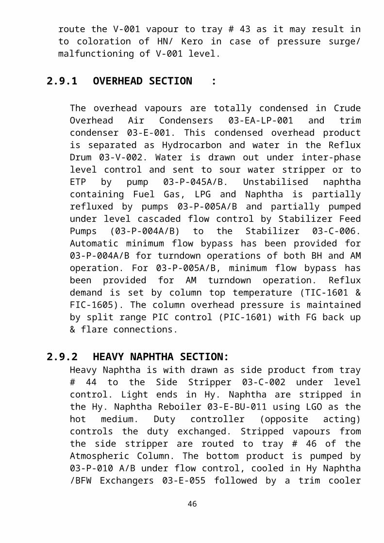
Safety relief valve discharge from desalters is routed above 10th tray. Pre flashed vapour from V-001 is also routed on same tray. As an alternative, vapours from V-001 can be routed on tray 43, in Kero/ATF section. This option is exercised to realise greater energy savings. When CDU operation is stable and level in pre flash vessel is steady, its vapours can be diverted to tray 43. Care should be taken to ensure that there is no level surge and subsequent crude carry over from V-001. However, in normal practice it is not advisable to route the V-001 vapour to tray # 43 as it may result in to coloration of HN/ Kero in case of pressure surge/ malfunctioning of V-001 level.
2.9.1 OVERHEAD SECTION :
The overhead vapours are totally condensed in Crude Overhead Air Condensers 03-EA-LP-001 and trim condenser 03-E-001. This condensed overhead product is separated as Hydrocarbon and water in the Reflux Drum 03-V-002. Water is drawn out under inter-phase level control and sent to sour water stripper or to ETP by pump 03-P-045A/B. Unstabilised naphtha containing Fuel Gas, LPG and Naphtha is partially refluxed by pumps 03-P-005A/B and partially pumped under level cascaded flow control by Stabilizer Feed Pumps (03-P-004A/B) to the Stabilizer 03-C-006. Automatic minimum flow bypass has been provided for 03-P-004A/B for turndown operations of both BH and AM operation. For 03-P-005A/B, minimum flow bypass has been provided for AM turndown operation. Reflux demand is set by column top temperature (TIC-1601 & FIC-1605). The column overhead pressure is maintained by split range PIC control (PIC-1601) with FG back up & flare connections.
2.9.2 HEAVY NAPHTHA SECTION:Heavy Naphtha is with drawn as side product from tray # 44 to the Side Stripper 03-C-002 under level control. Light ends in Hy. Naphtha are stripped in the Hy. Naphtha Reboiler 03-E-BU-011 using LGO as the hot medium. Duty controller (opposite acting) controls the duty exchanged. Stripped vapours from the side stripper are routed to tray # 46 of the Atmospheric Column. The bottom product is pumped by 03-P-010 A/B under flow control, cooled in Hy Naphtha /BFW Exchangers 03-E-055 followed by a trim cooler 03-E-007 and sent to storage.Presently 3P-10A/B is not run and the product is sent to rundown by gravity itself under level control.
33

34

2.9.3 KERO SECTIONKero is withdrawn as side product from tray # 31 to the Kero side stripper 03-C-003 under level control. Light ends in Kero are stripped in the Kero Reboiler 03-E-BU-012A/B using HVGO CR as the hot medium. Duty controller (opposite acting) controls the duty exchanged. Stripped vapours from the side stripper are routed to tray # 33 of the Atmospheric Column. The bottom product is routed to MP Steam Generator 03-E-053 followed by LMP Steam Generator (03-P-54) and Crude Preheat exchanger 03-E-021 (to reduce vapour pressure & hence increase available NPSH) before being pumped by 03-P-11 A/B. The discharge of 03P-11A/B routed to crude preheat exchangers (03-E-020 &013) and finally cooled in 03-EA-LP-006 and trim cooler 03-E-008A/B before being routed under flow control to storage. Min. flow bypass for the pump has been provided for AM/BH turndown operations.
2.9.4 LIGHT GAS OIL SECTION
LGO is withdrawn as side product from tray # 22 to the LGO side Stripper 03-C-004 under level control. Light ends in LGO are stripped using MP steam. Stripped vapours from the side stripper are routed to tray # 24 of the Atmospheric Column. The bottom product is pumped by 03-P-12 A/B under flow control through Hy. Naphtha Reboiler, (03-E-BU-011), Crude preheat exchangers (03-E-026 A/B and 019 and finally cooled in tempered water exchanger (03-E-041), air coolers (03-EA-LP-003A/B) and trim cooler (03-E-009) before being routed to storage. Min. flow bypass for the pump has been provided for AM/BH turndown operation.
Facilities have also been provided to route part of LGO ex 03-E-009 to Flushing Oil Header and also to Visbreaker Unit. Facility has also been provided to supply hot LGO to DHDS from up stream of 03-E-09.
2.9.5 HEAVY GAS OIL SECTION :
HGO is withdrawn from tray # 15 to the HGO side stripper 03-C-005 under level control. Light ends in HGO are stripped using MP steam. Stripped vapours from the side stripper are routed to tray # 18 of the Atmospheric Column. The bottom product is routed to preheat exchanger 03-E-035 (to improve NPSH available) before being pumped (by 03-P-013A/B) through preheat exchangers (03-E-031 & 023), tempered water exchanger 03-E-040 and coolers 03-EA-LP-004 & 03-E-010 before being finally routed to storage on Flow Control. Facility has been provided to supply hot HGO to DHDS from up stream of 03-E-10.
35

2.9.6 REDUCED CRUDE OIL
Stripped RCO drawn from the bottom of 03-C0-001 is pumped by RCO pumps 03-P-014 A/B/C to the Vacuum heater of vacuum Distillation Unit on Level control. Single pump will operate during turndown operation for both AM/BH operations. Starts up lines connect RCO to VR pump discharge line. Provision to route RCO to VR, and to route RCO through HVGO PDT & CR circuit and finally through VR product cooler 04-E-009 is also provided to cater to short period of operation of CDU without VDU operation. To control the charge pump suction temperature during hot circulation of the unit additional facility has also been provided to cool the circulation liquid of HVGO CR circuit in LVGO tempered water cooler 04-E-04.
2.9.7 CIRCULATING REFLUXES
In order to maximise heat recovery and balance tower loadings, heat is removed by way of circulating reflux (or pump arounds) from each of the sections. These pump arounds are withdrawn and pumped through preheat train for maximum heat recovery, thus cooling these streams. Duty controllers are provided for removing the requisite duty. HGO CR is used to reboil the Stabilizer Bottom in the Reboiler 03-E-BU-003 A/B. LGO CR is used for generating LP Steam. For turndown operations single pump will operate for HN/Kero/LGO/HGO CR pumps.
2.10 NAPHTHA STABLIZER SECTION
Unstabilised Naphtha from Crude Column overhead is pumped to the Naphtha Stabilizer 03-C-006 after preheating with stabilizer bottoms in the Feed/Bottom exchanger 03-E-052 on FIC/LIC cascade. A bypass of 03-E-52 has been provided to maintain NSU feed temperature in the range of 85-90 º C and stabiliser feed temperature about 125- 128 º C. This column has 40 trays with feed entering on the 21st tray. Necessary heat to reboil is provided by HGO-CR to the Horizontal Thermosyphon Reboiler 03-E-BU-003 A/B on Flow control (opposite acting). Temperature on tray # 3 regulates HGO CR flow through the reboiler.
36

37

38

39

40

41

42

43

A. LPG :
Stabiliser overhead vapors are condensed in the overhead condenser 03-E-002 and then flow into the reflux drum on PIC control. The stabilizer works either on partial condensation mode or total condensation mode. During full condensation PV-1901A is under control action and PV-1904 under control operation. Any water present with the overheads and separated in the Reflux drum 03-V-003 and part of Hydrocarbons refluxed under FIC/TIC cascade. The balance (LPG) is pumped to Caustic & Amine treating Unit for treatment on LIC/FIC control by pumps 03-P-015A/B. These pumps are provided with double mechanical seal with methanol as seal fluid releasing to flare on pressurisation. Min. flow bypass has been provided for turndown operations for both AM/BH.
Fuel Gas generated during BH/AM operation is routed to Amine Treatment Unit (located within CDU/VDU unit) to remove H2S before being routed to the Fuel gas KO Drum 03-V-027 and then to the plant Fuel Gas Distribution Header.
B.STABILIZED NAPHTHA :
Naphtha from stabiliser bottom after exchanging heat with feed Naphtha in 03-E-052 is routed to the Naphtha Splitter 03-C-007, on FIC/LIC control. In case naphtha splitter is shutdown, the stabilised naphtha is cooled in 03-EA-LP-11 and sent to rundown through CRU naphtha caustic wash system. However, if naphtha splitter is in operation 03-EA-LP-11 is kept bypassed.
Provision is also made to divert unstabilised Naphtha to slop header during start up.
2.11 NAPHTHA SPLITTER SECTION
In the Naphtha Splitter, 03-C-007, stabilized Naphtha is split to C5-65/90º C and 65/90-120/140 ºC cuts as overhead and bottom product respectively. This column has 26 trays with feed entering on 12 th tray. Provision to route feed to tray # 16th and 9th are also provided. The column overhead pressure is maintained by PIC control.
44

45
46
NAPHTHA SPLITTER

47

A)NAPHTHA SPLITTER OVERHEAD PRODUCT :
The overhead vapour is condensed in Air cooler 03-EA-LP-002 and the condensed product flows to the reflux drum 03-V-004 from where a part is refluxed back to the column on FIC/TIC control. This overhead product is further cooled to 40º C in 03-E-004 before being routed to storage via Caustic Wash on FIC/ LIC control. Min. flow bypass has been provided for pumps 03-P-016A/B for turndown operations.
B) NAPHTHA SPLITTER BOTTOM PRODUCT :
The bottom product is cooled in air cooler 03-EA-LP-007A/B followed by 03-E-042 to 40 º C before being routed to storage via a separate caustic wash on FIC/LIC control. Two control valves were provided in parallel to cater to the wide variations in flow between the various operations. However, based on actual experience the control valve provided for AM crude operation, has been removed. Common pumps 03-P-020A/B/C are provided for the furnace feed and product. During turndown, single pump will operate at the requisite capacity.
C) NAPHTHA SPLITTER REBOILER The heat for reboiling is provided by a fired heater 03-F-002. The heater can be fired with FO/FG or combination fuel. Vacuum heater and Naphtha Splitter fired reboiler share a common Air preheating system. Firing is controlled by temperature on the 3rd tray. For better control Coil Outlet Temperature, the principles of pass balancing is used. This is a vertical cylindrical Heater having six flows passes. The radiant section is provided with 6” Sch. 40 tubes having two 8” Sch. 40 tubes as last and second last tubes at the outlet of each pass while the pass while the connection section is provided with 6” Sch. 40 tubes. The radiant section tubes are disposed in a vertical arrangement along the walls of the combustion chamber.
The heater is provided with 12 forced draft, low NOx combination fuel fired burners (fuel oil & Refinery fuel gas). These burners are arranged in a circle and are fired vertically upward from the floor.
The convection section of Naphtha Splitter Reboiler has 8 Nos. of soot blowers, which are controlled by automatic sequential control panel provided at grade level.
48

49

A combined air preheater system containing one cast Air preheater and one Glass Air preheater alongwith two forced draft fans and one induced draft fan is provided for both Vacuum Heater and Splitter Reboiler.
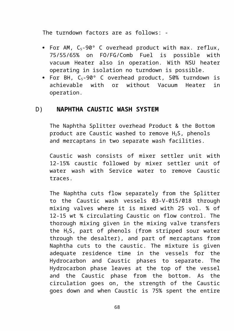
The turndown factors are as follows: -
For AM, C5-90º C overhead product with max. reflux, 75/55/65% on FO/FG/Comb Fuel is possible with vacuum Heater also in operation. With NSU heater operating in isolation no turndown is possible.
For BH, C5-90º C overhead product, 50% turndown is achievable with or without Vacuum Heater in operation.
D)NAPHTHA CAUSTIC WASH SYSTEM
The Naphtha Splitter overhead Product & the Bottom product are Caustic washed to remove H2S, phenols and mercaptans in two separate wash facilities.
Caustic wash consists of mixer settler unit with 12-15% caustic followed by mixer settler unit of water wash with Service water to remove Caustic traces.
The Naphtha cuts flow separately from the Splitter to the Caustic wash vessels 03-V-015/018 through mixing valves where it is mixed with 25 vol. % of 12-15 wt % circulating Caustic on flow control. The thorough mixing given in the mixing valve transfers the H2S, part of phenols (from stripped sour water through the desalter), and part of mercaptans from Naphtha cuts to the caustic. The mixture is given adequate residence time in the vessels for the Hydrocarbon and Caustic phases to separate. The Hydrocarbon phase leaves at the top of the vessel and the Caustic phase from the bottom. As the circulation goes on, the strength of the Caustic goes down and when Caustic is 75% spent the entire Caustic is drained out.. Shorter batch times may be required with heavier feed mercaptans.
The Hydrocarbon phase is then sent for water wash in vessels 03-V-016/019 to remove entrained Caustic, water is circulated by pumps 03-P025/028 respectively, for the overhead and bottom products, and the hydrocarbon is thoroughly mixed with water in the mixing valve upstream of the wash water vessel. Here again 25-vol. % of service water is circulated on flow control.
50

The washed Naphtha cuts are routed to storage on flow control. Pumps 03-P-024B and 03-P-027B are common stand by for 03-P-025 and 03-P-028 respectively.Spent caustic from the tanks 03-V-015/018 are transferred to spent caustic drum 03-V-017 and pumped at controlled rates to WWTP.Presently both naphtha splitter streams go to rundown without caustic and water circulation.
2.12 MTO SPLITTER SECTION
Part of Kero/ATF, upstream of the Product Rundown Control Valve is pumped to the MTO Splitter 03-C-008 by pumps 03-P-041A/B on flow control after exchanging heat with MTO bottom product (Hy. Kero) in 03-E-051A/B/C. Presently the above pumps have been removed as sufficient pressure is available in the kero rundown system to push kero to splitter column. The balance heat required is provided by HVGO CR in the Horizontal Thermosyphon Reboiler 03-E-BU-006 on flow control (opposite acting). Temperature on the 3rd tray regulates HVGO CR flow through the reboiler.The column is designed with 26 trays with feed entering on the 10th tray. Provision to route the feed to the 8th tray is also provided.
A.MTO SPLITTER OVERHEAD :
The overhead pressure is controlled by PIC control. The overheads are condensed in a tempered water Exchanger 03-E-044 and routed to the Reflux Drum 03-V-005 from where a part of the condensed products is refluxed on FIC control and the rest pumped on LIC/FIC control to Kero/ATF rundown line after cooling in 03-E-050. Min. flow bypass for pump 03-P-017A/B is provided to cater to AM turndown operation.
B.MTO PRODUCT :
This product is drawn from a total draw tray below tray # 19 by pumps 03-P-030A/B. A part is refluxed on FIC control and the balance cooled in 03-EA-LP-008 and 03-E-047, before being rundown to storage on LIC/FIC control. During BH operation this stream is blended with Kero/ATF rundown line.
C.HEAVY KERO (MTO SPLITTER BOTTOM) :The bottom product is pumped by 03-P-019A/B and finally cooled in 03-E-048 and routed to storage on flow control. During AM operation this product is blended with Kero/ATF in the rundown line. Min. flow bypass has been provided to cater to turndown operation.
51

52

53

54

BASIC DESIGN PROCEDURE AND THEORY
The general equation for heat transfer across a surface is:
where Q = heat transferred per unit time, W, U = the overall heat transfer coefficient, W/m2 0 C,
A = heat-transfer area, m2, = the mean temperature difference, the temperature driving
force, 0 C
The prime objective in the design of an exchanger is to determine the surface area required for the specified duty (rate of heat transfer) using the temperature differences available.The overall coefficient is the reciprocal of the overall resistance to heat transfer, whichis the sum of several individual resistances. For heat exchange across a typical heatexchanger tube the relationship between the overall coefficient and the individual coefficients, which are the reciprocals of the individual resistances, is given by
Where Uo =the overall coefficient based on the outside area of the tube, W/m2 0 C,
ho = outside fluid film coefficient, W/m2 0 C,hi = inside fluid film coefficient, W/m2 0 C,hod = outside dirt coefficient (fouling factor), W/m2 0 C,hid = inside dirt coefficient, W/m2 0 C,kw = thermal conductivity of the tube wall material, W/m0 C,di = tube inside diameter, m,do = tube outside diameter, m.
The magnitude of the individual coefficients will depend on the nature of the heattransfer process (conduction, convection, condensation, boiling or radiation), on the physical properties of the fluids, on the fluid flow-rates, and on the physical arrangement of the heat-transfer surface. As the physical layout of the exchanger cannot be determined until the area is known the design of an exchanger is of necessity a trial and error procedure. The steps in a typical design procedure are given below
55

1. Define the duty: heat-transfer rate, fluid flow-rates, temperatures.2. Collect together the fluid physical properties required: density, viscosity, thermal conductivity.3. Decide on the type of exchanger to be used.4. Select a trial value for the overall coefficient, U.5. Calculate the mean temperature difference 6. Calculate the area required from equation 7. Decide the exchanger layout.8. Calculate the individual coefficients.9. Calculate the overall coefficient and compare with the trial value. If the
Calculated value differs significantly from the estimated value, substitute the calculated for the estimated value and return to step 6.
10. Calculate the exchanger pressure drop; if unsatisfactory return to steps 7 or 4 or 3, in that order of preference.
11. Optimise the design: repeat steps 4 to 10, as necessary, to determine the cheapest exchanger that will satisfy the duty. Usually this will be the one with the smallest area.
MEAN TEMPERATURE DIFFERENCE (TEMPERATUREDRIVING FORCE)
Before equation 1 can be used to determine the heat transfer area required for a given duty, an estimate of the mean temperature difference Tm must be made. This will normally be calculated from the terminal temperature differences: the difference in the fluid temperatures at the inlet and outlet of the exchanger. The well-known “logarithmic mean” temperature difference is only applicable to sensible heat transfer in true co-current or counter-current flow (linear temperature enthalpy curves). For counter-current flow, Figure 12.18a, the logarithmic mean temperatureis given by:
where =log mean temperature difference, T1 = hot fluid temperature, inlet, T2 = hot fluid temperature, outlet, t1 =cold fluid temperature, inlet, t2 = cold fluid temperature, outlet
56

The equation is the same for co-current flow, but the terminal temperature differences will be (T1 - t1) and (T2 -t2). Strictly, equation 4 will only apply when there is no change in the specific heats, the overall heat-transfer coefficient is constant, and there are no heat losses. In design, these conditions can be assumed to be satisfied providing the temperature change in each fluid stream is not large. In most shell and tube exchangers the flow will be a mixture of co-current, countercurrent and cross flow. Figures 12.18b and c show typical temperature profiles for an exchanger with one shell pass and two tube passes (a 1 : 2 exchanger). Figure 12.18cshows a temperature cross, where the outlet temperature of the cold stream is above that of the hot stream.The usual practice in the design of shell and tube exchangers is to estimate the “true temperature difference” from the logarithmic mean temperature by applying a correction factor to allow for the departure from true counter-current flow.
where true temperature difference, the mean temperature difference for use in the design equation 1,Ft = the temperature correction factor.
The correction factor is a function of the shell and tube fluid temperatures, and the number of tube and shell passes. It is normally correlated as a function of two dimensionless temperature ratios:
57

And
R is equal to the shell-side fluid flow-rate times the fluid mean specific heat; divided by the tube-side fluid flow-rate times the tube-side fluid specific heat.S is a measure of the temperature efficiency of the exchanger.For a 1 shell : 2 tube pass exchanger, the correction factor is given by
58

The derivation of equation is given by Kern (1950). The equation for a 1 shell : 2 tube pass exchanger can be used for any exchanger with an even number of tube passes, and is plotted in Figure 12.19. The correction factorfor 2 shell passes and 4, or multiples of 4, tube passes is shown in Figure , and that for divided and split flow shells in Figures
59

Temperature correction factor plots for other arrangements can be found in the TEMA standards and the books by Kern (1950) and Ludwig (2001). Mueller (1973) gives a comprehensive set of figures for calculating the log mean temperature correction factor, which includes figures for cross-flow exchangers.
The following assumptions are made in the derivation of the temperature correction factor Ft, in addition to those made for the calculation of the log mean temperature difference:
1. Equal heat transfer areas in each pass.2. A constant overall heat-transfer coefficient in each pass.3. The temperature of the shell-side fluid in any pass is constant across any crosssection.4. There is no leakage of fluid between shell passes.
60

Though these conditions will not be strictly satisfied in practical heat exchangers, the Ft values obtained from the curves will give an estimate of the “true mean temperature difference” that is sufficiently accurate for most designs. Mueller (1973) discusses these assumptions, and gives Ft curves for conditions when all the assumptions are not met.
The shell-side leakage and bypass streams will affect the mean temperature difference, but are not normally taken into account when estimating the correction factor Ft. Fisher and Parker (1969) give curves which show the effect of leakage on the correction factor for a 1 shell pass : 2 tube pass exchanger.
The value of Ft will be close to one when the terminal temperature differences are large, but will appreciably reduce the logarithmic mean temperature difference when the temperatures of shell and tube fluids approach each other; it will fall drastically when there is a temperature cross. A temperature cross will occur if the outlet temperature of the cold stream is greater than the inlet temperature of the hot stream, Figure.
Where the Ft curve is near vertical values cannot be read accurately, and this will introduce a considerable uncertainty into the design.An economic exchanger design cannot normally be achieved if the correction factor Ft falls below about 0.75. In these circumstances an alternative type of exchanger should be considered which gives a closer approach to true counter-current flow. The use of two or more shells in series, or multiple shell-side passes, will give a closer approach to true counter-current flow, and should be considered where a temperature cross is likely to occur.Where both sensible and latent heat is transferred, it will be necessary to divide the temperature profile into sections and calculate the mean temperature difference for each section.
61

SHELL AND TUBE EXCHANGERS: GENERAL DESIGNCONSIDERATIONS
Where no phase change occurs, the following factors will determine the allocation of the fluid streams to the shell or tubes.
Corrosion. The more corrosive fluid should be allocated to the tube-side. This will reduce the cost of expensive alloy or clad components.
Fouling. The fluid that has the greatest tendency to foul the heat-transfer surfaces should be placed in the tubes. This will give better control over the design fluid velocity, and the higher allowable velocity in the tubes will reduce fouling. Also, the tubes will be easier to clean.
Fluid temperatures. If the temperatures are high enough to require the use of special alloys placing the higher temperature fluid in the tubes will reduce the overall cost. At moderate temperatures, placing the hotter fluid in the tubes will reduce the shell surface temperatures, and hence the need for lagging to reduce heat loss, or for safety reasons.
Operating pressures. The higher pressure stream should be allocated to the tube-side. High-pressure tubes will be cheaper than a high-pressure shell.
Pressure drop. For the same pressure drop, higher heat-transfer coefficients will be obtained on the tube-side than the shell-side, and fluid with the lowest allowable pressure drop should be allocated to the tube-side.
Viscosity. Generally, a higher heat-transfer coefficient will be obtained by allocating the more viscous material to the shell-side, providing the flow is turbulent. The critical Reynolds number for turbulent flow in the shell is in the region of 200. If turbulent flow cannot be achieved in the shell it is better to place the fluid in the tubes, as the tube-side heat-transfer coefficient can be predicted with more certainty.
Stream flow-rates. Allocating the fluids with the lowest flow-rate to the shell-side will normally give the most economical design.
62

TUBE-SIDE HEAT-TRANSFER COEFFICIENT ANDPRESSURE DROP (SINGLE PHASE)
Turbulent flow
Heat-transfer data for turbulent flow inside conduits of uniform cross-section are usually correlated by an equation of the form
where Nu = Nusselt number Re = Reynolds number Pr = Prandtl number hi=inside coefficient,de = equivalent (or hydraulic mean) diameter, m
Ut= fluid velocity, m/s,Kf= fluid thermal conductivity, W/m 0C,Gt = mass velocity, mass flow per unit area, kg/m 2s,µ= fluid viscosity at the bulk fluid temperature, Ns/m2,µw=fluid viscosity at the wall,Cp= fluid specific heat, heat capacity, J/kg 0C
The index for the Reynolds number is generally taken as 0.8. That for the Prandtl number can range from 0.3 for cooling to 0.4 for heating. The index for the viscosity factor is normally taken as 0.14 for flow in tubes, from the work of Sieder and Tate (1936), but some workers report higher values. A general equation that can be used for exchanger design is
63

It is not really possible to find values for the constant and indexes to cover the complete range of process fluids, from gases to viscous liquids, but the values predicted using equation 12.11 should be sufficiently accurate for design purposes. The uncertainty in the prediction of the shell-side coefficient and fouling factors will usually far outweigh any error in the tube-side value. Where a more accurate prediction than that given by equation required, and justified, the data and correlations given in the Engineering Science Data Unit reports are recommended: ESDU 92003 and 93018 (1998). Butterworth (1977) gives the following equation, which is based on the ESDU work
Hydraulic mean diameter
In some texts the equivalent (hydraulic mean) diameter is defined differently for use in calculating the heat transfer coefficient in a conduit or channel, than for calculating the pressure drop. The perimeter through which the heat is being transferred is used in place of the total wetted perimeter. In practice, the use of de calculated either way will makelittle difference to the value of the estimated overall coefficient; as the film coefficient is only, roughly, proportional to d_0.2e .It is the full wetted perimeter that determines the flow regime and the velocity gradients in a channel. So, in this book, de determined using the full wetted perimeter will be used for both pressure drop and heat transfer calculations. The actual area through which the heat is transferred should, of course, be used to determine the rate of heat transfer;
Laminar flow
Below a Reynolds number of about 2000 the flow in pipes will be laminar. Providing the natural convection effects are small, which will normally be so in forced convection, the following equation can be used to estimate the film heat-transfer coefficient
64

Where L is the length of the tube in metres.If the Nusselt number given by equation is less than 3.5, it should be taken as 3.5.In laminar flow the length of the tube can have a marked effect on the heat-transfer rate for length to diameter ratios less than 500.
Transition region
In the flow region between laminar and fully developed turbulent flow heat-transfer coefficients cannot be predicted with certainty, as the flow in this region is unstable, and the transition region should be avoided in exchanger design. If this is not practicable the coefficient should be evaluated using both equations and the least value taken.
Heat-transfer factor, jh
It is often convenient to correlate heat-transfer data in terms of a heat transfer “j” factor, which is similar to the friction factor used for pressure drop . The heat-transfer factor is defined by:
The use of the jh factor enables data for laminar and turbulent flow to be represented on the same graph;. The jh values obtained from Figure can be used with equation to estimate the heat-transfer coefficients for heat-exchanger tubes and commercial pipes. The coefficient estimated for pipes will normally be conservative (on the high side) as pipes are rougher than the tubes used for heat exchangers, which are finished to closer tolerances. Equation can be rearranged to a more convenient form
Note. Kern (1950), and other workers, define the heat transfer factor as
65

The relationship between jh and jH is given by:
Viscosity correction factor
The viscosity correction factor will normally only be significant for viscous liquids.To apply the correction an estimate of the wall temperature is needed. This can be made by first calculating the coefficient without the correction and using the following relationship to estimate the wall temperature
where t = tube-side bulk temperature (mean),tw = estimated wall temperature,T = shell-side bulk temperature (mean).
Usually an approximate estimate of the wall temperature is sufficient, but trial-and-error calculations can be made to obtain a better estimate if the correction is large.
66

Coefficients for waterThough equations 12.11 and 12.13 and Figure 12.23 may be used for water, a more accurate estimate can be made by using equations developed specifically for water. The physical properties are conveniently incorporated into the correlation. The equation below has been adapted from data given by Eagle and Ferguson (1930):
Tube-side pressure drop
There are two major sources of pressure loss on the tube-side of a shell and tube exchanger: the friction loss in the tubes and the losses due to the sudden contraction and expansion and flow reversals that the fluid experiences in flow through the tube arrangement.
The tube friction loss can be calculated using the familiar equations for pressure-drop loss in pipes . The basic equation for isothermal flow in pipes (constant temperature) is:
where jf is the dimensionless friction factor and L’ is the effective pipe length
The flow in a heat exchanger will clearly not be isothermal, and this is allowed for by including an empirical correction factor to account for the change in physical properties with temperature. Normally only the change in viscosity is considered:
67
Values of jf for heat exchanger tubes can be obtained from Figure.
The pressure losses due to contraction at the tube inlets, expansion at the exits, andflow reversal in the headers, can be a significant part of the total tube-side pressure drop. There is no entirely satisfactory method for estimating these losses. Kern (1950) suggestsadding four velocity heads per pass. Frank (1978) considers this to be too high, andrecommends 2.5 velocity heads. Butterworth (1978) suggests 1.8. Lord et al. (1970) take the loss per pass as equivalent to a length of tube equal to 300 tube diameters for straighttubes, and 200 for U-tubes; whereas Evans (1980) appears to add only 67 tube diametersper pass.The loss in terms of velocity heads can be estimated by counting the number of flow contractions, expansions and reversals, and using the factors for pipe fittings to estimate the number of velocity heads lost. For two tube passes, there will be two contractions, two expansions and one flow reversal. The head loss for each of these effects is: contraction 0.5, expansion 1.0, 180Ž bend 1.5; so for two passes the maximum loss will be
From this, it appears that Frank’s recommended value of 2.5 velocity heads per pass is the most realistic value to use.Combining this factor with equation gives
Another source of pressure drop will be the flow expansion and contraction at the exchanger inlet and outlet nozzles. This can be estimated by adding one velocity head for the inlet and 0.5 for the outlet, based on the nozzle velocities.
68

69

Kern’s method
This method was based on experimental work on commercial exchangers with standard tolerances and will give a reasonably satisfactory prediction of the heat-transfer coefficient for standard designs. The prediction of pressure drop is less satisfactory, as pressure drop is more affected by leakage and bypassing than heat transfer. The shell-side heat transfer and friction factors are correlated in a similar manner to those for tube-side flow by using a hypothetical shell velocity and shell diameter. As the cross-sectional area for flow will vary across the shell diameter, the linear and mass velocities are based on the maximum area for cross-flow: that at the shell equator. The shell equivalent diameter is calculated using the flow area between the tubes taken in the axial direction (parallel to the tubes) and the wetted perimeter of the tubes; see Figure
Shell-side jh and jf factors for use in this method are given in Figures, for various baffle cuts and tube arrangements. These figures are based on data given by Kern (1950) and by Ludwig (2001).The procedure for calculating the shell-side heat-transfer coefficient and pressure drop for a single shell pass exchanger is given below:
Procedure
1. Calculate the area for cross-flow As for the hypothetical row of tubes at the shell equator, given by
70

The term (pt – do)/pt is the ratio of the clearance between tubes and the total distance between tube centres.
2. Calculate the shell-side mass velocity Gs and the linear velocity us:
3. Calculate the shell-side equivalent diameter (hydraulic diameter), Figure For a square pitch arrangement
4. Calculate the shell-side Reynolds number, given by:
For the calculated Reynolds number, read the value of jh from Figure for the selected baffle cut and tube arrangement, and calculate the shell-side heat transfer coefficient hs from:
71

72

73

The tube wall temperature can be estimated using the method given for the tube-side,
a. For the calculated shell-side Reynolds number, read the friction factor from figure and calculate the shell-side pressure drop from:
Shell nozzle-pressure drop
The pressure loss in the shell nozzles will normally only be significant with gases. The nozzle pressure drop can be taken as equivalent to 3/2 velocity heads for the inlet and 1/2 for the outlet, based on the nozzle area or the free area between the tubes in the row immediately adjacent to the nozzle, whichever is the least.
EXAMPLE:-
Design an exchanger to sub-cool condensate from a condenser from 950C to 40 0C. Flow-rate of methanol 100,000 kg/h. Brackish water will be used as the coolant, with a temperature rise from 25 0C to 40 0C.
Only the thermal design will be considered.This example illustrates Kern’s method.Coolant is corrosive, so assign to tube-side
Heat capacity feed = 2.84 kJ/kg 0C
74

Use one shell pass and two tube passes
Choose 20 mm o.d., 16 mm i.d., 4.88-m-long tubes(3/4 in x 16 feet) cupro-nickel.
Allowing for tube-sheet thickness, takeL = 4.83 m
As the shell-side fluid is relatively clean use 1.25 triangular pitch.
75

The coefficient can also be calculated using equation this is done to illustrate use of this method
76

Checks reasonably well with value calculated from equation use lower figure
77

78

79

80

BASIC DESIGN PROCEDURE OF A MULTI-COMPONENT DISTILLATION COLOUM
The basic background and understanding of binary distillation applies to a large measure in multicomponent problems.
Multicomponent distillation are more complicated than binary systems due primarily to the actual or potential involment or interaction of one or more components of the multicomponent system on other the components of the mixture.These interaction may be in the form of vapour –liquid equilibriums such as azeotrope formation , or chemical r eactions, etc., any of which may affect the activity relations, and hence deviations from ideal relationships. For example, some system are known to have two azeotrope combinations in the distillation coloum.
Sometimes these, one or all, can be “broken” or changed in the vapour pressure relationships by addition of a third chemical or hydrocarbon . To properly handle the changing composition relationship it is almost essential to utilize some electronic computer techniques if good accuracy is to be achieved. Even three component systems become tedious using desk size electronic calculator without significant internal memory. Computers can be well programmed to handle the complexities of trial and check for convergence to a present acceptable limit.
Technique for convergence of digital computer program are often the heart of an efficient multicomponent calculation . There are several technique incorporated into many programs.
KEY COMPONENTS
The two component in a feed mixture whose sepration will be specified.
1.Adajacent keys: Key component that are adajacent with respect to their volatilities.
2.Split keys: Key component that are separated in volatilities by a non-key component ,i.e., the system of components contains one or more whose volatilities fall between the volatilities of the designed keys.
3.Light keys: The designation of the key component with the highest volatilities of the two key components.
81

4.Heavy keys: The designation of the key component with the lowest volatilities of the two components.
Hengstebeck present a simplified procedure for reducing a multicomponent system to an equivalent binary using the “key” components. From this the number of stages or theoretical plates and reflux can be determined using conventional binary procedures and involving the McCabe-Thiele method.
Liddle present a shortcut technique for multicomponent calculations based on improving the Fenke-Gilliland correlations.
MINIMUM REFLUX RATIO –INFINITE PLATES:
This is the smallest value of external reflux ratio (L/D) which can be used to obtain a specified sepration . This is not a operable condition. Knowledge of the minimum reflux ratio aids considerably in establishing an economical and practical operation ratio. Ratios of 1.2 to 2 times the minimum in the economical range for hydrocarbon chemical system. However ,it is well to recognize that high reflux rate increase the coloum size (but reduce the number of tray required ), reboiler size steam rate ,condensetr size ,and coolant rate. For adjacent key systems, all components heavier than the heavy key appear only in bottom ,all the component lighter than the light key appear only in overhead ,and the keys each appear in the overhead and bottoms in accordance with specifications.
For a split key system the lights and heavies distribute the same as for adjacent key system. However , the components between the keys also distribute to overead and bottoms.
At minimum reflux , the region in which the number of trays approaches to infinity.(called pinch zones and region of constant compositions )are:
1.Binary system: pinch zone adjacent to feed plate.2. Multicomponent:a. Three component with no component lighter than light key: pinch zone in stripping section adjacent to feed plate.b. Three component with no component heavier than heavy key: pinch zone in rextifying section adjacent to feed plate.c. Three component mixture: pinch zones may be above and below feed
pate.d. Greater than four components: pinch zones appear in rectifying and stripping sections.
82

For system one side stream draw off, either above or below the feed. Tsuo et al . propose a method for recognizing that the minimum reflux ratio is greater for a column with sidestream draw off . At the sidestream the operating line has an inflection. For multifeed distillation systems, the minimum reflux is determined by factoring together the separate effect of each feed. Lesi process a detailed graphical procedure for figuring multicomponent minimum reflux by a graphical extension of a Mc-Cabe-thiele diagram, assuming infinite plates or equilibrium stages. In this traditional model the concentration in the distillate of the component heavier than the heavy key components are assumed to be zero, and the heavy key component reaches its maximum concentration a+, the upper pinch point. Therefore ,this assumption is that only the heavy and light keys are presentat the upper pinch point, similar in concept to the handling of a binary mixture.
The method assume:
(a) only the key component are distributed
(b) no split key component exist
(c) total molal overflow rates and relative volatilities are constant.
This method provides good agreement with the detailed method of Underwood.
Yaws et al. provide an estimating technique for recovery of each component in the distillate and bottom from multicomponent distillation using equations and involving the specification of the recovery of the each component in the distillate, the recovery of the heavy component in the bottoms, and the relative volatility of the light key component. The result compare very well wih plate-to- plate calculation, for a wide range of recovery of 0.05 to 99.93% in the distillate . The distribution of components for the distillate and the bottoms is give by the Hengstebeck-Geddes equation
log (di/bi)= A + B log ai
Where di = moles of component i in the distillate bi = moles of component i in the bottoms ai = relative volatility of component i A,B = correlation constant
A material balance for the i component in the feed is:
fi = di + bi
83

Then the quantity of component i in the distillate can be expressed as a mole fraction recovered , or d i/fi ,. Likewise , the molefraction of component i recovered in the bottoms is bi/fi , or 1-di/fi , substituting into:
log ( (di/fi) / (1-(di/fi) ) ) = A + B log ai
solving for recovery of component i in the distillate gives :
di/fi = (10AaiB )/(1+ 10Aai
B)
from a material balance recovery of component i in the bottoms is
bi/fi = 1 /(1+ 10A aiB)
The correlation constants required obtained by specifying a desired recovery of the light key component LK in the distillate and the recovery of the heavy key component HK in the bottoms. Then the constants are calculated as follows:
A = -log { (bHK /fHK) /1- (bHK /fHK ) }
B= log { (dLK /fLK) /1- (dLK /fLK ) X (bHK /fHK) /1- (bHK /fHK ) } / log αLK
STEPS INVOLVED IN MULTICOMPONENT DISTILLATION COLOUM DESIGN :
A. UNDERWOOD ALGEBRIC METHOD ADJACENT KEY SYSTEMS :
This system for evaluating multicomponent adjacent keys system , assuming constant relative volatility and constant molal overflow , has proven generally satisfactory for many chemical and hydrocarbon applicati((αaxa)D/αa –θ) ons. It gives a rigorous solution for constant molal overflow and volatility , and acceptable result s for most cases which deviate from these limitations .
Overall coloum constant :
(L/D)MIN + 1 =((αaxa)D/αa –θ) + ((αbxb)D/αb –θ) +…… + ((αixi)D/αi –θ)
84

In arriving at (L/D)MIN the correct value of θ is obtained from:
1-q = ((αaxa)F/αa –θ) + ((αbxb)F/αb –θ) +…… + ((αixi)F/αi –θ) =∑ XFi / 1- θ/ αi
The q value is the same as previously described for the thermal condition of the feed.
RECTIFYING SECTION ONLY :
Vr = ∑ DXDi /(1-θ/ αi )
STRIPPING SECTION ONLY:
VS = ∑ BXBi /(1-θ/ αi )
At the minimum reflux condition all the θ values are equal , and generally related :
αh ‹ θ ‹ αi
STEP 1 : Expressing θ and q value by trial and error , noting that θ will have a value between the α of a heavy key and the α of a light key evaluated at or near pinch temperatures , or at α avg. suggested
tabulation , starting with an assumed θ value ,θa :
Component XFi αi XFi αi – θ αi XFi / αi – θ αi XFi / (αi – θ) 2 a XFa αa XFa αa – θ αa XFa /( αa – θ) αa XFa / (αa – θ)2 b XFb αb XFb αb – θ αb XFb /( αb – θ) αb XFb / (αb – θ)2
• • • • __________ ____________ ∑ψ(θa) ∑ ψ’(θa)
corrected θ by Newtons approximation method :θc = θ(assumed) – ψ(θa)/ ψ’(θa)
Repeat the same type of tabular computation , substituting the corrected the θ for the θa. if the second corrected θa ,checks closely with θa , the value of θ has been obtained , if not ,a third recalculation should be made using the θ’s value as the new assumed value .
85

Note that the average α values should b used (constant ) for each component unless the values vary considerably through the column. In
this latter case follow the discussion given elsewhere in this section.
STEP 2: Calculated (L/D)min by substituting the final θ value solving for (L/D)MIN . note that this requires evaluating the functions associated with θ at the composition of the distillate product. The α values are the constant values previously used above.
UNDERWOOD ALGEBRIC METHOD ADJACENT KEY SYSTE M: VARIABLE α
For a varying systems , the following procedure is suggested.
STEP 1: assume (L/D)min and determine the pinch temperature by Colburn method.
STEP 2: At this temperature , evaluate α at pinch and α at overhead temperature ,obtaining a geometric average α . as an alternate , Shiras indicates α avg. value which gives acceptable result s when compared to pinch and stepwise calculation. This suggestion calculates,
tavg. =(Dt0/BtB)/F
STEP 3: Determine uderwood θ value as previously described, using the average a value.
STEP 4: Calculate (L/D)min and compare with assumed value of (1)
above. If check is satisfactory, (L/D)MIN is complete, if not reassume new value (L/D)min using calculated value as basis ,and repeat (1) through (4) until satisfactory check is obtained.
Where, t0 =overhead temp., 0F tB= bottoms temp., 0F t..p = avg.temp., 0F
To aid in solving the tedious Underwood equation to ultimately arrive at (L/D)min , Frank has developed , which applies for liquid feed at its bubble point and whether the system is binary or multicomponent , but dose require that the key component are adjacent . otherwise ,the system must be solved for two values of θ . to obtain the necessary parameters for figure 8-47, Frank recommends using the same overhead concentrations that were used in or calculated by the Fenske equation for the Underwood solution.( θ = Underwood constant ) .
86

CONCLUSION
STUDY OF CHARACTERISTICS OF RAW MATERIAL & PRODUCTS:-
Collection of data regarding the characteristics of raw materials employed such as crude oil, its source & other chemicals and utilities involved in preprocessing and processing of raw crude into various useful forms.
Study and collection of data regarding the desired characteristics of products obtained from atmospheric and vacuum columns like Liquefied Petroleum Gas, Kerosene, Aviation Turbine Fuel, Motor Spirit etc.
STUDY OF PROCESS DESCRIPTION INCLUDING VISIT TO REFINERY:-
Study of various process involved in the Atmospheric & Vacuum Unit starting from the transportation of raw crude oil from its source till the processing carried out in distillation columns viz. Atmospheric & Vacuum columns.
This requires a visit to IOCL Mathura Refinery for the purpose of study of description of various processes being carried out in industry for processing of crude oil. It also involves the preparation of flow sheets of various processes involved showing various streams designation and requisite equipments with their numbering.
COLLECTION OF DATA IN REGARD OF OPERATING PARAMETER FOR VARIOUS EQUIPMENTS AND PRODUCT SPECIFICATION FOR VARIOUS PROCESSES:
Visit to IOCL MATHURA REFINERY would also involve sourcing and collection of data for the purpose of design of various equipments. This involve noting down inlet and outlet operating temperature ,top and bottom operating pressure ,feed flow rate etc. data would be collected for various equipment such as heat exchanger ,storage vessels, distillation columns ,furnace etc.
87

DESIGN OF EQUIPMENT :
Finally using the operating data of equipment and software like fluent , flosheet ,chemsep ,matlab, etc. and following design procedures as specified in various references texts like coulson & Richardson’s chemical engineering series volume 6 etc.
88

REFERENCES
L. C. Waterman, Crude desalting: Why & how, Hydrocarbon Processing, Vol. 14, No. 2, pp.133-138 (1965)
B. G. S. Marzano, Electric desalting in oil refineries, The Institute of Petroleum, April-June, pp. 113-117 (1989).
G. D. Hobson, Ed., Modern Petroleum Technology, Part II, 5 th ed., John Wiley & Sons, Chichester, (1984).
N. C. Kothari, H. K. Mulchandani, C. S. Sharma and J. Prakash, Dearomatising of naptha-Techno-economics aspects, CEW, Vol.XXIII, No.3.
D. A. Bea, Jet fuel needs more kerosenes, Fydrocarbon Processing, Vol. 67, No.12
Dr. Ram Prasad, Petroleum Refining Technology by Khanna publishers.
89