PROGRESSIVE COLLAPSE ANALYSIS OF MULTI STOREY STEEL ...
10
PROGRESSIVE COLLAPSE ANALYSIS OF MULTI STOREY STEEL STRUCTURE WITH BRACING SYSTEMS Rekha M N 1 , Dr. S Vijaya 2 , Dr. B SHIVAKUMARA SWAMY 3 1 PG student in Structural Engineering, Dr. AIT, Bengaluru, Karnataka, India 2,3 Professor, Department of Civil Engineering, Dr. AIT, Bengaluru, Karnataka, India Abstract:Progressive collapse refers to the phenomenon in which the local damage of a primary structural element leads to total or partial structural system failure, without any proportionality between the initial and final damage. Even if the probability of structural collapse is low, if it occurs, it can cause significant losses. In the past few decades, many incidents of the total or partial collapse of structures due to fire, explosions or impacts have occurred. In the present study, Multi storey structure is considered. The modelling and analysis are carried out using E-tabs software. The different bracing systems are used to analysis the structural behavior. The Structure is later verified for progressive collapse analysis at 3 different locations such as corner, Centre and middle of the structure. The progressive analysis is carried out and results are extracted and discussed. The displacement control can be easily achieved by providing bracings. The displacement of bare frame models can be reduced by 55%, 55% and 63% by adopting bracings such as Diagonal bracing, V Bracing and X Bracing systems. The progressive collapse analysis shows the failure of upper level beams. It is estimated that, the maximum increase in percentage of DCR value for beams are around 38%, 52% and 59% for location A, B and C respectively. And hence the beams are super designed for these additional capacities to avoid progressive collapse. From the overall results, it is concluded that, the bracings are very much necessary for the reductions of displacement and drift effect in a building. However, its Importance is not of much use in case of progressive collapse state. The X Bracings are preferred for bracing system. Keywords: Progressive collapse, equivalent static analysis, bracings, displacements, storey drift, base shear, time period, acceleration, E-Tabs 1. Introduction A structure could be subjected to more than one critical action during its entire service period. It may be a manmade or natural disaster can lead to structural instability which influences the partial or complete collapse of the building. Natural disasters include earthquake, wind blast or fire. And these manmade disasters include terrorist attack or gas cylinder explosion or instant removal of the primary structural element. progressive collapse is one outcome of these critical loads. The progressive collapse can be defined as a situation where local failure of a primary structural component leads to total collapse of the structure. Progressive collapse happens when relatively local structural damage, causes a chain reaction of structure elements failures, disproportionate to the initial damage, causing in partial or full collapse of the building. Local damage that initiates progressive collapse of building is called initiating damage. In general, progressive collapse occurs in a very short time in seconds. It is also possible that it can be characterized by the loss of load- carrying capacity of a relatively small portion of a building due to a typical load which, in turn initiates a fall of failures affecting a main portion of the structure. ISSN No: 0130-7673 Page No: 19 NOVYI MIR Research Journal Volume 5, Issue 11, 2020
Transcript of PROGRESSIVE COLLAPSE ANALYSIS OF MULTI STOREY STEEL ...

PROGRESSIVE COLLAPSE ANALYSIS OF MULTI STOREY STEEL STRUCTURE WITH
BRACING SYSTEMS
Rekha M N1, Dr. S Vijaya2, Dr. B SHIVAKUMARA SWAMY3 1PG student in Structural Engineering, Dr. AIT, Bengaluru, Karnataka, India
2,3Professor, Department of Civil Engineering, Dr. AIT, Bengaluru, Karnataka, India
Abstract:Progressive collapse refers to the phenomenon in which the local damage of a primary
structural element leads to total or partial structural system failure, without any proportionality
between the initial and final damage. Even if the probability of structural collapse is low, if it
occurs, it can cause significant losses. In the past few decades, many incidents of the total or
partial collapse of structures due to fire, explosions or impacts have occurred. In the present study,
Multi storey structure is considered. The modelling and analysis are carried out using E-tabs
software. The different bracing systems are used to analysis the structural behavior. The Structure
is later verified for progressive collapse analysis at 3 different locations such as corner, Centre
and middle of the structure. The progressive analysis is carried out and results are extracted and
discussed. The displacement control can be easily achieved by providing bracings. The
displacement of bare frame models can be reduced by 55%, 55% and 63% by adopting bracings
such as Diagonal bracing, V Bracing and X Bracing systems. The progressive collapse analysis
shows the failure of upper level beams. It is estimated that, the maximum increase in percentage of
DCR value for beams are around 38%, 52% and 59% for location A, B and C respectively. And
hence the beams are super designed for these additional capacities to avoid progressive collapse.
From the overall results, it is concluded that, the bracings are very much necessary for the
reductions of displacement and drift effect in a building. However, its Importance is not of much
use in case of progressive collapse state. The X Bracings are preferred for bracing system.
Keywords: Progressive collapse, equivalent static analysis, bracings, displacements, storey drift,
base shear, time period, acceleration, E-Tabs
1. Introduction
A structure could be subjected to more than one critical action during its entire service period. It
may be a manmade or natural disaster can lead to structural instability which influences the partial
or complete collapse of the building. Natural disasters include earthquake, wind blast or fire. And
these manmade disasters include terrorist attack or gas cylinder explosion or instant removal of the
primary structural element. progressive collapse is one outcome of these critical loads.
The progressive collapse can be defined as a situation where local failure of a primary structural
component leads to total collapse of the structure. Progressive collapse happens when relatively
local structural damage, causes a chain reaction of structure elements failures, disproportionate to
the initial damage, causing in partial or full collapse of the building. Local damage that initiates
progressive collapse of building is called initiating damage. In general, progressive collapse occurs
in a very short time in seconds. It is also possible that it can be characterized by the loss of load-
carrying capacity of a relatively small portion of a building due to a typical load which, in turn
initiates a fall of failures affecting a main portion of the structure.
ISSN No: 0130-7673
Page No: 19
NOVYI MIR Research Journal
Volume 5, Issue 11, 2020

To minimize the progressive collapse of the structure bracings provides stability and resists
lateral loads. In case of steel structure to resist the lateral force and increase thestiffness of steel
frame, bracings play very vital role. Bracing will make structure indeterminate. But it stiffens the
structure and also helps to resist the sway of the structure. Bracings are straight member and carry
only axial forces. Generally, the use of bracings instead of Shear walls provides lower stiffness and
resistance for a structure but it should not beforgotten that such a system has lower weightand more
useful for architectural purposes. Use of braces for seismic rehabilitation of structures should not
cause any torsion disorder and designers should be aware of increasing the axial loads of columns
in bracing panels. The probable uplift in columns and foundations should be controlled too.
A. Bracings
Bracing systems are very simple to construct and also to understand the theory behind it. This
system is the economic way to construct a lateral load resisting system. These systems are in
expensive and works exactly like truss behaviour. It will not transfer the bending moment. It can
only transfer the axial loads. Bracing mainly take care of lateral loads whereas frames take care of
axial loads.
The primary function of bracings is to provide stability and resist lateral loads, either from diagonal
steel members or from concrete ‘core’. Due to bracing, displacement of the structure gets reduced
considerably it is up to 90% but in case of X-bracing material required will be more and hence V
or Inverted V bracing effectively resist the displacement as compared to all other types of bracings.
Using bracing systems axial reaction is reduced and hence the footing size also gets reduced. Also,
reduction in moment at base will definitely help to reduce the size of the footing and due to bracing
the torsional moment in base column increases.
In this study the different bracings such as Diagonal bracing, V Bracing and X Bracing systems are
used to analysis the structural behavior. The Structure is later verified for progressive collapse
analysis at 3 different locations such as corner, Centre and middle of the structure. The progressive
analysis is carried out and results are extracted and discussed activity. However, fully braced
systems are having highest rigidity compared to partially braced system. The biggest aim of the
engineer is to achieve the highest stability of the structure with nominal structural cost. The Shear
wall and Bracing systems are found to be suitable in achieving this. These systems are also reliable
and works effective under lateral force effect.
In this present study, 20 storey building is considered for the analysis. And attempts are made to
study the behavior of the structure in severe wind and earthquake zones of India and seven models
(bare frame, bare frame with V bracing, bare frame with inverted V bracing, bare frame with
diagonal bracing, bare frame with X bracing, bare frame with shear wall at centre and bare frame
with shear wall at ends) are analyzed using ETABS 2017 software by equivalent static method of
analysis, dynamic response spectrum method of analysis and wind analysis. The results of analysis
in terms of time period, frequency, displacements, storey drifts, base shear are obtained.
2. Objectives The following objectives are considered in the present studies
1. To Study the behaviour of Multi storey steel structure.
2. To understand the behaviour of structure when accidental collapse of columns for various
locations.
3. To study the various bracings system such as Diagonal, V and X bracings.
4. To understand the comparison of different models based on the parameters such as
displacement, Storey drift, base shear, time period, acceleration.
ISSN No: 0130-7673
Page No: 20
NOVYI MIR Research Journal
Volume 5, Issue 11, 2020

3. Methodology Steel structure is modelled, designed as per IS-800-2007 the models are analysed for Static
Analysis and progressive collapse. The modelling is carried out using FEM based ETABS
software. Results are obtained from gravity loads and then lateral loads are applied to check the behaviour of
the models and Results are extracted for X direction only.
4. MODELLING AND ANALYSIS In the present study, 8 storey structure is considered. Totally sixteen number of models are created
and analysed. The model details are listed below. There are four major models, i.e., M1, M2, M3
and M4 represents are. M1 - Multi storey steel structure without bracings.
M2 - Multi storey steel structure with diagonal bracings.
M3 - Multi storey steel structure with V bracings.
M4 - Multi storey steel structure with X bracings.
However, the remaining models are the same models with removal of column location A, B and C
respectively and here it is representing model with removal of column at position A only and
showing its graphical representation.
The model is 8 storey height with regular structure.
Seismic Zone III
Seismic Zone Factor (Z) 0.16
Importance Factor (I) 1.5
Response Reduction Factor
4
Damping Ratio 0.05
Soil Type Hard Soil (Type I)
Height of the building 32m (8 Storey)
Story to story Height 4.0 m
Span Length 5m
Column used ISMB
Thickness of Slab 125 mm
Floor Finish 1.0 KN/m2
Live Load 3.0 KN/m2
Grade of Concrete(fck) M35
Grade of Structural Steel (fys)
Fe 350
Grade of Reinforcing Steel
Fe 500
Table 1: Material properties and design parameters
ISSN No: 0130-7673
Page No: 21
NOVYI MIR Research Journal
Volume 5, Issue 11, 2020
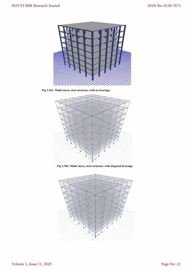
Fig 1:M1- Multi storey steel structure with no bracings
Fig 2:M2- Multi storey steel structure with diagonal bracings
ISSN No: 0130-7673
Page No: 22
NOVYI MIR Research Journal
Volume 5, Issue 11, 2020

Fig 3:M3- Multi storey steel structure with V bracings
Fig 4:M4- Multi storey steel structure with X bracings
5. Results and Discussion The models are first loaded with gravity loads and then lateral loads are applied to check the
behaviour of the models. Since, the models are symmetrical in both X and Y direction, the results
are extracted for X direction only.
The structural results of various analysis of M1, M2, M3 and M4 are discussed below.
A. Displacement Equivalent static analysis
The displacement of models in X direction is tabulated and presented below.
Fig 5 :Storey v/s Displacement in x direction_EQX
Figure 5 representing storey v/s displacement of equivalent static analysis. We can observe that as
the storey increases displacement also increases irrespective of the model.
The displacement of the model 1 is more compared to all other models with bracings. The
displacement is reducing drastically for models with bracings. However, the model with X bracing
exhibiting lowest displacement among other types of bracings because the lateral stiffness of the
system increases and the stability of the system improves.
0
1
2
3
4
5
6
7
8
9
10
0 20 40 60 80 100
ST
OR
EY
in
No
's
DISPLACEMENT in mm
EQUIVALENT STATIC ANALYSIS
MODEL 1
MODEL 2
MODEL 3
MODEL 4
ISSN No: 0130-7673
Page No: 23
NOVYI MIR Research Journal
Volume 5, Issue 11, 2020

B. Storey Drift Equivalent static analysis
Fig 6: Storey v/s Drift in x direction_EQX
Figure 6 representing storey v/s Drift of equivalent static analysis and drift is defined as ratio of
displacement of two consecutive floor to height of that floor.
The drift values are almost same in case of models with bracings i.e., M2, M3 and M4.
However, it is noticed that, the model without bracing are having largest drift values. This
proves, bracings can high influence on drift control.
C. Base shear Equivalent static analysis Base shear is the shear force at base or foundation level. The following table indicates the
base shear value for different configurations.
Fig 7: Base shear comparison of M1, M2, M3 and M4
Figure 7 showing the base shear values are same for all the models and the model 2 exhibiting
more shear compared to all other models shear forces in columns increases from unbraced to
braced system i.e., only minor variations. However, static analysis base shear will be only
dependent upon the weight of the structure and hence all the base shear values are similar.
0
2
4
6
8
10
0 5
10
15
20
ST
OR
EY
DRIFT
EQUIVALENT STATIC ANALYSIS
MODEL 1
MODEL 2
MODEL 3
MODEL 4
1060 1070 1080 1090 1100 1110
MODEL 1
MODEL 2
MODEL 3
MODEL 4
MODEL 1 MODEL 2 MODEL 3 MODEL 4
Series1 1082 1107 1086 1089
BASE SHEAR
ISSN No: 0130-7673
Page No: 24
NOVYI MIR Research Journal
Volume 5, Issue 11, 2020

D. Time period Equivalent static analysis
Fig 8: Time period v/s Mode shapes
Figure 8 representing time period v/s mode shape the time period of the model M1 is more and
flexible comparedto all other models. The introduction of bracing reduces the flexibility. However,
the X bracing model is showing highest rate of reduction of time period and hence rigid compared
to other models.
E. Frequency Equivalent static analysis
Fig 9: Frequency v/s Mode shapes
From the figure 9, the model having highest rigidity factors are having more frequency. The model
M4 with X bracing possess highest frequency than other models.
F. Progressive Collapse Analysis
Progressive collapse analysis has been performed as per GSA specification. In case of regular
framed structure removal of one column at corner (Location A), middle (Location B) at exterior
frame and middle at immediate interior frame at middle (Location C) of the building is done as per
GSA specification. Since in this work, Structural systems has been considered, where distance
between columns are 6 m, column is assumed to be collapsed (supporting Storey 1) at locations as
shown in Figures below.
0.00
0.50
1.00
1.50
2.00
2.50
3.00
0 5 10 15
TIM
E P
ER
IOD
MODE SHAPE
MODEL 1
MODEL 2
MODEL 3
MODEL 4
0.00
2.00
4.00
6.00
8.00
10.00
12.00
0 10 20
FR
EQ
UE
NC
Y
MODE SHAPE
MODEL 1
MODEL 2
MODEL 3
MODEL 4
ISSN No: 0130-7673
Page No: 25
NOVYI MIR Research Journal
Volume 5, Issue 11, 2020

Fig 10: Assumed column removal location A
1. DCR ratios for beams
Fig 11: DCR Ratio of Beam 71 for Column Removal @ Location A
Figure 11 representing the beams at storey
However, the models with bracings are showing adverse effect with increase in DCR ratios for
Model M2, M3 and M4.
0.731
0
0.2
0.4
0.6
0.8
1
1.2
MODEL 1
DC
R R
AT
IO
C O L U M N R E M O V A L L O C A T I O N
Fig 10: Assumed column removal location A Plan view
DCR ratios for beams
Fig 11: DCR Ratio of Beam 71 for Column Removal @ Location A
Figure 11 representing the beams at storey 1 is failing due to removal of column location A.
However, the models with bracings are showing adverse effect with increase in DCR ratios for
0.731 0.738 0.736 0.733
1.0961.14 1.126 1.125
MODEL 1 MODEL 2 MODEL 3 MODEL 4
MODELS
C O L U M N R E M O V A L L O C A T I O N A
NO PC
PC. LOC A
1 is failing due to removal of column location A.
However, the models with bracings are showing adverse effect with increase in DCR ratios for
ISSN No: 0130-7673
Page No: 26
NOVYI MIR Research Journal
Volume 5, Issue 11, 2020

2.DCR ratios for column
Fig 12: DCR Ratio of Column 25 for Column Removal @ Location A
Figure 12 showing the DCR ratio of Models with bracings are more compared to model M1. This
diagonal bracing model is worst among all other types of bracing system, since the model 2 is
having highest DCR Ratio.
5.CONCLUSIONS
Based on the results and discussions, the following conclusions are drawn,
From the overall results, it is concluded that, the bracings are very much necessary for the
reductions of displacement and drift effect in a
much use in case of progressive collapse state. The X Bracings are preferred for bracing
system.
The progressive collapse analysis shows the failure of upper level beams. It is estimated that,
the maximum increase in percentage of DCR value for beams are around 38%, 52% and 59%
for location A, B and C respectively. And hence the beams are super designed for these
additional capacities to avoid progressive collapse.
In the similar way, the Axial load increas
For Column removal location A, B and C respectively. And hence additional loads should be
predicted earlier to avoid Progressive collapse.
From the progressive collapse analysis, it is found that, the DCR ra
for removal adjacent.
6. REFERENCES
[1] Meng-Hao Tsai, Tsuei
Building with Exterior Non
[2] HadiFaghihmaleki (2017), “Assessment of Robustness Index and Progressive Collapse in
the RC Frame with Shear Wall Structure under Blast Loading”. Journal of applied
Research on industrial Engineering, Volume 4, No 1, 59
[3] H.M. Salema , A.K. El
design of reinforced concrete structures against progressive collapse”. Engineering
structures 33(2011) 3341
0.825
0
0.2
0.4
0.6
0.8
1
1.2
1.4
MODEL 1
DC
R R
AT
IO
C O L U M N R E M O V A L L O C A T I O N
2.DCR ratios for column
Fig 12: DCR Ratio of Column 25 for Column Removal @ Location A
Figure 12 showing the DCR ratio of Models with bracings are more compared to model M1. This
diagonal bracing model is worst among all other types of bracing system, since the model 2 is
Based on the results and discussions, the following conclusions are drawn,
From the overall results, it is concluded that, the bracings are very much necessary for the
reductions of displacement and drift effect in a building. However, its Importance is not of
much use in case of progressive collapse state. The X Bracings are preferred for bracing
The progressive collapse analysis shows the failure of upper level beams. It is estimated that,
increase in percentage of DCR value for beams are around 38%, 52% and 59%
for location A, B and C respectively. And hence the beams are super designed for these
additional capacities to avoid progressive collapse.
In the similar way, the Axial load increase in the column is found to be 25%, 25% and 20%.
For Column removal location A, B and C respectively. And hence additional loads should be
predicted earlier to avoid Progressive collapse.
From the progressive collapse analysis, it is found that, the DCR ratio of column increase only
Hao Tsai, Tsuei-Chiang Huang (2014), “Progressive Collapse Analysis of an RC
Building with Exterior Non-Structural Walls”. Science Direct, 14, 377-384.
(2017), “Assessment of Robustness Index and Progressive Collapse in
the RC Frame with Shear Wall Structure under Blast Loading”. Journal of applied
Research on industrial Engineering, Volume 4, No 1, 59-66.
H.M. Salema , A.K. El-Fouly b, , H.S. Tagel-Dinb, (2011), “Toward an economic
design of reinforced concrete structures against progressive collapse”. Engineering
structures 33(2011) 3341-3350.
0.8250.912
0.832 0.835
1.1221.238
1.14 1.145
MODEL 1 MODEL 2 MODEL 3 MODEL 4
MODELS
C O L U M N R E M O V A L L O C A T I O N A
NO PC
PC. LOC A
Fig 12: DCR Ratio of Column 25 for Column Removal @ Location A
Figure 12 showing the DCR ratio of Models with bracings are more compared to model M1. This
diagonal bracing model is worst among all other types of bracing system, since the model 2 is
From the overall results, it is concluded that, the bracings are very much necessary for the
building. However, its Importance is not of
much use in case of progressive collapse state. The X Bracings are preferred for bracing
The progressive collapse analysis shows the failure of upper level beams. It is estimated that,
increase in percentage of DCR value for beams are around 38%, 52% and 59%
for location A, B and C respectively. And hence the beams are super designed for these
e in the column is found to be 25%, 25% and 20%.
For Column removal location A, B and C respectively. And hence additional loads should be
tio of column increase only
Chiang Huang (2014), “Progressive Collapse Analysis of an RC
384.
(2017), “Assessment of Robustness Index and Progressive Collapse in
the RC Frame with Shear Wall Structure under Blast Loading”. Journal of applied
b, (2011), “Toward an economic
design of reinforced concrete structures against progressive collapse”. Engineering
ISSN No: 0130-7673
Page No: 27
NOVYI MIR Research Journal
Volume 5, Issue 11, 2020

[4] Mehrdad Sasani (2008), “Response of a reinforced concrete infilled-frame structure to
removal of two adjacent columns”. Engineering structures 30, 2478-2491.
[5] Florea Dinu a,b, , IoanMarginean a,1 , Dan Dubina (2017), “ Experimental testing and
numerical modelling of steel moment-frame connections under column loss”. Engineering
structures 151(2017) 861-878.
[6] Ifteqhar Ahmed Khan, B. Narender (2019), “Effect of Steel Bracing in Progressive
Collapse of Multi Storey RC Buildings”. International Journal of Recent Technology and
Engineering (IJRTE), ISSN: 2277-3878, Volume-8 Issue-4, November 2019.
[7] Ashna T E1 ,Nivya John (2015), “Progressive Collapse Analysis of a Regular
Structure”.International Journal Of Advanced Research in Engineering & Management
(IJAREM)| Vol. 01 - Issue 07, October 2015, 90.
[8] PanosPantidis, Ph.D, Liling Cao, Ph.D, and Simos Gerasimidis, Ph.D.3 (2020), “Partial
Damage Distribution and Progressive Collapse of Buildings”. Structures Congress,52-62.
[9] Rinsha C1, Biju Mathew2 (2017), “Progressive collapse analysis of steel frame
structures”. International Research Journal of Engineering and Technology (IRJET),
Volume: 04 Issue: 05, May -2017.
[10] Yuan Zhoua,b , She L. Wang*a ,Nan Zhaoa , Fu Y. Li (2016), “Experimental Research
and Finite Element Analysis of Progressive Collapse Resistance of RC”, The Italian
Association of Chemical Engineering, VOL. 51, 1015-1020.
ISSN No: 0130-7673
Page No: 28
NOVYI MIR Research Journal
Volume 5, Issue 11, 2020