progressive collapse
181
UFC 4-023-03 14 July 2009 Including Change 1 – 27 January 2010 UNIFIED FACILITIES CRITERIA (UFC) DESIGN OF BUILDINGS TO RESIST PROGRESSIVE COLLAPSE APPROVED FOR PUBLIC RELEASE; DISTRIBUTION UNLIMITED
-
Upload
riyaz-siddique -
Category
Documents
-
view
159 -
download
2
description
progressive collapse in flat slab
Transcript of progressive collapse

UFC 4-023-03 14 July 2009
Including Change 1 – 27 January 2010
UNIFIED FACILITIES CRITERIA (UFC)
DESIGN OF BUILDINGS TO RESIST PROGRESSIVE COLLAPSE
APPROVED FOR PUBLIC RELEASE; DISTRIBUTION UNLIMITED

UFC 4-023-03 14 July 2009
Including Change 1 – 27 January 2010
UNIFIED FACILITIES CRITERIA (UFC)
DESIGN OF BUILDINGS TO RESIST PROGRESSIVE COLLAPSE
Any copyrighted material included in this UFC is identified at its point of use. Use of the copyrighted material apart from this UFC must have the permission of the copyright holder. U.S. ARMY CORPS OF ENGINEERS NAVAL FACILITIES ENGINEERING COMMAND (Preparing Activity) AIR FORCE CIVIL ENGINEER SUPPORT AGENCY Record of Changes (changes are indicated by \1\ ... /1/) Change No. Date Location 1 Changed all references from UFC 3-310-01 "Structural
Load Data" to UFC 3-301-01 "Structural Engineering" 27 January 2010
This UFC supersedes UFC 4-023-03, dated 25 January, 2005.

UFC 4-023-03 1 February 2009
FOREWORD The Unified Facilities Criteria (UFC) system is prescribed by MIL-STD 3007 and provides planning, design, construction, sustainment, restoration, and modernization criteria, and applies to the Military Departments, the Defense Agencies, and the DoD Field Activities in accordance with USD(AT&L) Memorandum dated 29 May 2002. UFC will be used for all DoD projects and work for other customers where appropriate. All construction outside of the United States is also governed by Status of Forces Agreements (SOFA), Host Nation Funded Construction Agreements (HNFA), and in some instances, Bilateral Infrastructure Agreements (BIA.) Therefore, the acquisition team must ensure compliance with the more stringent of the UFC, the SOFA, the HNFA, and the BIA, as applicable. UFC are living documents and will be periodically reviewed, updated, and made available to users as part of the Services’ responsibility for providing technical criteria for military construction. Headquarters, U.S. Army Corps of Engineers (HQUSACE), Naval Facilities Engineering Command (NAVFAC), and, Air Force Center for Engineering and the Environment (AFCEE) are responsible for administration of the UFC system. Defense agencies should contact the preparing service for document interpretation and improvements. Technical content of UFC is the responsibility of the cognizant DoD working group. Recommended changes with supporting rationale should be sent to the respective service proponent office by the following electronic form: Criteria Change Request (CCR). The form is also accessible from the Internet sites listed below. UFC are effective upon issuance and are distributed only in electronic media from the following source: Whole Building Design Guide web site http://dod.wbdg.org/. Hard copies of UFC printed from electronic media should be checked against the current electronic version prior to use to ensure that they are current. AUTHORIZED BY:
______________________________________ JAMES C. DALTON, P.E. Chief, Engineering and Construction U.S. Army Corps of Engineers
______________________________________ JOSEPH E. GOTT, P.E. Chief Engineer Naval Facilities Engineering Command
______________________________________ PAUL A. PARKER The Deputy Civil Engineer DCS/Installations & Logistics Department of the Air Force
______________________________________ MICHAEL McANDREW Director, Facility Investment and Management Office of the Deputy Under Secretary of Defense (Installations and Environment)

UFC 4-023-03 14 July 2009
A-2
UNIFIED FACILITIES CRITERIA (UFC) REVISION SUMMARY SHEET
Subject: UFC 4-023-03, Design of Structures to Resist Progressive Collapse Cancels: UFC 4-023-03, Design of Structures to Resist Progressive Collapse, Dated 25 January, 2005 Reasons for Change. UFC 4-023-03 was updated for the following reasons:
• Incorporation of new knowledge related to the design of buildings to resist progressive collapse; this includes test data and analytic models for
o Steel beam-column connections o Wood structure under blast damage and collapse loading o Reinforced concrete slab response to large deformations o Load and dynamic increase factors to account for inertial effects and
nonlinear geometry and material behavior; • Resolution of contradictions in terminology for structural concepts; • Clarification of ambiguities and imprecise guidance for linear static, nonlinear
static, and nonlinear dynamic structural analysis methods; • Removal of structural hardening requirements (floor upward load and double
column height requirements); • Update of example problems; • Expansion of applicability to other government agencies.
Description of Changes. This update to UFC 4-023-03 is a significant revision to the 25 January 2005 version. The significant changes include:
• Replacement of levels of protection with occupancy categories, to determine the required level of progressive collapse design;
• Definition of a story • Inclusion of Appendix B. Definitions, with descriptions of the key terms and
structural analysis concepts. • Revision of the levels of progressive collapse design, including the option to use
the Alternate Path Method in lieu of Tie Forces, for Occupancy Category II; • Removal of the floor upward loads and doubled column height requirements; • Revision of the Tie Force method, including force magnitudes and locations of
Tie Forces; • Adoption of modeling parameters and acceptance criteria from ASCE 41 Seismic
Rehabilitation of Existing Buildings; • Implementation of the “m-factor” approach for Linear Static analysis; • Inclusion of Load Increase Factors for Linear Static models and Dynamic
Increase Factors for Nonlinear Static models; • Removal of requirement to perform peer reviews of Alternate Path designs • Clarification of size and location of load-bearing wall removal;

UFC 4-023-03 14 July 2009
A-3
• Replacement of the Additional Ductility Requirements with Enhanced Local Resistance;
• Revision of the three example problems (Reinforced Concrete, Steel, and Wood) to reflect the updated UFC 4-023-03.
Impact. The impact of this updated UFC 4-023-03 will vary depending upon the particular structure, structure type, location, and function. The degree of protection against progressive collapse is more consistently applied due to the use of occupancy categories to define the consequences of an event. Considering the building inventory as a whole, resistance to progressive collapse will be the same or greater as for the 25 January 2005 version. Due to the implementation of new knowledge relative to Tie Forces, steel connections, and wood structures, and due to the adoption of the ASCE 41 modeling parameters and acceptance criteria, the criteria has a more widely accepted engineering basis and more consistent design results.
For all buildings, but in particular existing buildings, the removal of the floor upward load and doubled column height requirements will result in significant savings, without compromising the progressive collapse resistance of the building. For steel buildings designed to meet the Tie Force requirements, the material costs for the Tie Force elements will be slightly to moderately greater due to the increased force requirements; however, labor cost increase will be marginal. For structures meeting the Alternate Path requirements, the costs should not be significantly different than from the 25 January 2005 version, but this will depend upon the particular structure. Non Unified Issues. Document content is unified and consistent for all services and agencies of the Department of Defense.

UFC 4-023-03 14 July 2009
i
CONTENTS
CHAPTER 1 INTRODUCTION ................................................................................. 11
Page
1-1 PURPOSE AND SCOPE. ........................................................ 11 1-2 APPLICABILITY. ...................................................................... 11 1-2.1 Building Type and Story Height. .............................................. 11 1-2.2 Clarification for Partial Occupancy. .......................................... 11 1-2.3 Application by Other Organizations. ........................................ 11 1-3 GENERAL................................................................................ 12 1-3.1 Significance of Progressive Collapse. ...................................... 12 1-3.2 Hardening of Structures to Resist Initial Damage. ................... 12 1-3.3 Risk Considerations. ................................................................ 13 1-3.4 Design Approaches. ................................................................ 13 1-3.4.1 Direct Design Approaches. ...................................................... 13 1-3.4.2 Indirect Design Approaches. .................................................... 13 1-4 SUMMARY OF THE PROGRESSIVE COLLAPSE DESIGN
PROCEDURE. ......................................................................... 14 1-5 REFERENCES. ....................................................................... 14 1-6 INSPECTION REQUIREMENTS. ............................................ 14 1-7 SECURITY ENGINEERING UFC SERIES. ............................. 14
CHAPTER 2 PROGRESSIVE COLLAPSE DESIGN REQUIREMENTS .................. 16
FOR NEW AND EXISTING CONSTRUCTION ............................................................. 16
2-1 OCCUPANCY CATEGORY DETERMINATION. ..................... 16 2-2 DESIGN REQUIREMENTS FOR NEW AND EXISTING
CONSTRUCTION. ................................................................... 17 2-2.1 Occupancy Category I Design Requirement. ........................... 17 2-2.2 Occupancy Category II Design Requirement. .......................... 17 2-2.2.1 Option 1 for Occupancy Category II: Tie Force and Enhanced
Local Resistance. .................................................................... 18 2-2.2.2 Option 2 for Occupancy Category II: Alternate Path. .............. 18 2-2.3 Occupancy Category III Design Requirement. ......................... 19 2-2.3.1 Alternate Path Requirement for Occupancy Category III. ........ 19 2-2.3.2 Enhanced Local Resistance Requirement for Occupancy
Category III. ............................................................................. 19 2-2.4 Occupancy Category IV Design Requirement. ........................ 19 2-2.4.1 Tie Force Requirement for Occupancy Category IV. ............... 19 2-2.4.2 Alternate Path Requirement for Occupancy Category IV. ........ 20 2-2.4.3 Enhanced Local Resistance Requirement for Occupancy
Category IV. ............................................................................. 20
CHAPTER 3 DESIGN PROCEDURES ..................................................................... 21

UFC 4-023-03 14 July 2009
ii
3-1 TIE FORCES. .......................................................................... 21 3-1.1 Load and Resistance Factor Design for Tie Forces. ................ 21 3-1.2 Floor Loads. ............................................................................. 23 3-1.2.1 Uniform Floor Load. ................................................................. 23 3-1.2.2 Consideration for Non-Uniform Load Over Floor Area. ............ 23 3-1.2.3 Cladding and Façade Loads. ................................................... 24 3-1.3 Required Tie Strength, Distribution, and Location. .................. 24 3-1.3.1 Longitudinal and Transverse Ties. ........................................... 25 3-1.3.2 Peripheral Ties. ........................................................................ 29 3-1.3.3 Vertical Ties. ............................................................................ 30 3-1.4 Continuity of Ties. .................................................................... 30 3-1.5 Splices, Anchorage, and Development of Ties. ....................... 31 3-1.5.1 Cast-in-Place Reinforced Concrete Floor and Roof Systems. . 31 3-1.5.2 Precast Concrete Floor and Roof Systems. ............................. 32 3-1.5.3 Composite Construction Floor and Roof Systems. .................. 32 3-1.5.4 Other Floor and Roof Systems and Structural Elements. ........ 32 3-1.6 Structural Elements and Connections With Inadequate Tie
Strength ................................................................................... 33 3-2 ALTERNATE PATH METHOD. ................................................ 33 3-2.1 General. ................................................................................... 33 3-2.2 Alternative Rational Analysis. .................................................. 33 3-2.3 Load and Resistance Factor Design for Alternate Path Method.
................................................................................................. 34 3-2.4 Primary and Secondary Components. ..................................... 35 3-2.5 Force-and Deformation-Controlled Actions. ............................. 35 3-2.6 Expected and Lower Bound Strength. ..................................... 36 3-2.7 Material Properties. .................................................................. 37 3-2.8 Component Force and Deformation Capacities. ...................... 37 3-2.8.1 Component Capacities for Nonlinear Procedures. ................... 37 3-2.8.2 Component Capacities for the Linear Static Procedure. .......... 38 3-2.9 Removal of Load-Bearing Elements for the Alternate Path
Method. .................................................................................... 39 3-2.9.1 Extent of Removed Load-Bearing Elements. ........................... 40 3-2.9.2 Location of Removed Load-Bearing Elements......................... 40 3-2.10 Structure Acceptance Criteria. ................................................. 42 3-2.11 Linear Static Procedure. .......................................................... 45 3-2.11.1 Limitations on the Use of LSP. ................................................. 45 3-2.11.2 Analytical Modeling. ................................................................. 46 3-2.11.3 Lateral Stability/P-Δ Effects. .................................................... 47 3-2.11.4 Loading. ................................................................................... 47 3-2.11.5 Load Increase Factor. .............................................................. 51 3-2.11.6 Design Forces and Deformations. ........................................... 51 3-2.11.7 Component and Element Acceptance Criteria. ........................ 52 3-2.12 Nonlinear Static Procedure. ..................................................... 53 3-2.12.1 Limitations on the Use of NSP. ................................................ 53 3-2.12.2 Analytical Modeling. ................................................................. 53 3-2.12.3 Lateral Stability/P-Δ Effects. .................................................... 54

UFC 4-023-03 14 July 2009
iii
3-2.12.4 Loading. ................................................................................... 54 3-2.12.5 Dynamic Increase Factor for NSP. .......................................... 55 3-2.12.6 Design Forces and Deformations. ........................................... 56 3-2.12.7 Component and Element Acceptance Criteria. ........................ 56 3-2.13 Nonlinear Dynamic Procedure. ................................................ 57 3-2.13.1 Limitations on the Use of NDP. ................................................ 57 3-2.13.2 Analytical Modeling. ................................................................. 57 3-2.13.3 Lateral Stability and P- Δ Effects. ............................................ 57 3-2.13.4 Loading. ................................................................................... 58 3-2.13.5 Design Forces and Deformations. ........................................... 59 3-2.13.6 Component and Element Acceptance Criteria. ........................ 59 3-3 ENHANCED LOCAL RESISTANCE. ....................................... 59 3-3.1 ELR Location Requirements. ................................................... 60 3-3.1.1 OC II Option 1. ......................................................................... 60 3-3.1.2 OC III. 60 3-3.1.3 OC IV. 60 3-3.2 Flexural Resistance Calculation. .............................................. 60 3-3.3 Flexural and Shear Resistance. ............................................... 60 3-3.3.1 OC II Option 1. ......................................................................... 60 3-3.3.2 OC III. 61 3-3.3.3 OC IV. 61
CHAPTER 4 REINFORCED CONCRETE ................................................................ 63
4-1 MATERIAL PROPERTIES FOR REINFORCED CONCRETE. 63 4-2 STRENGTH REDUCTION FACTOR Φ FOR REINFORCED
CONCRETE. ............................................................................ 63 4-3 TIE FORCE REQUIREMENTS FOR REINFORCED
CONCRETE. ............................................................................ 63 4-4 ALTERNATE PATH REquirements FOR REINFORCED
CONCRETE. ............................................................................ 63 4-4.1 General. ................................................................................... 63 4-4.2 Flexural Members and Joints. .................................................. 64 4-4.3 Modeling and Acceptance Criteria for Reinforced Concrete. ... 64 4-5 ENHANCED LOCAL RESISTANCE REQUIREMENTS FOR
REINFORCED CONCRETE. ................................................... 64
CHAPTER 5 STRUCTURAL STEEL ........................................................................ 69
5-1 MATERIAL PROPERTIES FOR STRUCTURAL STEEL. ........ 69 5-2 STRENGTH REDUCTION FACTOR Φ FOR STRUCTURAL
STEEL. .................................................................................... 69 5-3 TIE FORCE REQUIREMENTS FOR STEEL. .......................... 69 5-4 ALTERNATE PATH METHOD FOR STEEL. ........................... 69 5-4.1 General. ................................................................................... 69 5-4.2 Connection Rotational Capacity. .............................................. 69 5-4.3 Modeling and Acceptance Criteria for Structural Steel. ........... 70

UFC 4-023-03 14 July 2009
iv
5-5 ENHANCED LOCAL RESISTANCE REQUIREMENTS FOR STEEL. .................................................................................... 70
CHAPTER 6 MASONRY ........................................................................................... 73
6-1 MATERIAL PROPERTIES FOR MASONRY. .......................... 73 6-2 STRENGTH REDUCTION FACTOR Φ FOR MASONRY. ....... 73 6-3 TIE FORCE REQUIREMENTS FOR MASONRY. ................... 73 6-4 ALTERNATE PATH METHOD FOR MASONRY. .................... 73 6-4.1 General. ................................................................................... 73 6-4.2 Modeling and Acceptance Criteria for Masonry. ...................... 73 6-5 ENHANCED LOCAL RESISTANCE REQUIREMENTS FOR
MASONRY. .............................................................................. 74
CHAPTER 7 WOOD ................................................................................................. 75
7-1 MATERIAL PROPERTIES FOR WOOD. ................................. 75 7-2 STRENGTH REDUCTION FACTOR Φ FOR WOOD. ............. 75 7-3 TIME EFFECT FACTOR λ FOR WOOD.................................. 75 7-4 TIE FORCE REQUIREMENTS FOR WOOD. .......................... 75 7-5 ALTERNATE PATH METHOD FOR WOOD............................ 76 7-5.1 General. ................................................................................... 76 7-5.2 Modeling and Acceptance Criteria for Wood. .......................... 76 7-6 ENHANCED LOCAL RESISTANCE REQUIREMENTS FOR
WOOD. .................................................................................... 76
CHAPTER 8 COLD-FORMED STEEL ...................................................................... 77
8-1 MATERIAL PROPERTIES FOR COLD-FORMED STEEL. ..... 77 8-2 STRENGTH REDUCTION FACTOR Φ FOR COLD-FORMED
STEEL. .................................................................................... 77 8-3 TIE FORCE REQUIREMENTS FOR COLD-FORMED STEEL.
................................................................................................. 77 8-4 ALTERNATE PATH METHOD FOR COLD-FORMED STEEL. 77 8-4.1 General. ................................................................................... 77 8-4.2 Modeling and Acceptance Criteria for Cold-Formed Steel. ...... 77 8-5 ENHANCED LOCAL RESISTANCE REQUIREMENTS FOR
COLD-FORMED STEEL. ......................................................... 78
APPENDIX A REFERENCES .................................................................................... 79
APPENDIX B DEFINITIONS ...................................................................................... 82
B-1 INTRODUCTION. .................................................................... 82 B-2 TERMINOLOGY. ..................................................................... 82 B-3 DEFINITIONS FOR STRUCTURAL ANALYSIS
PROCEDURES. ...................................................................... 83

UFC 4-023-03 14 July 2009
v
APPENDIX C COMMENTARY ................................................................................... 90
C-1 INTRODUCTION. .................................................................... 90 C-2 APPLICABILITY. ...................................................................... 90 C-2.1 Three Story Requirement and Story Definition. ....................... 90 C-2.2 Clarification for Partial Occupancy. .......................................... 90 C-3 OCCUPANCY CATEGORIES. ................................................ 91 C-4 DESIGN REQUIREMENTS. .................................................... 91 C-4.1 OC I Design Requirement. ....................................................... 91 C-4.2 OC II Design Requirement. ...................................................... 91 C-4.2.1 OC II Option 1, Tie Forces and Enhanced Local Resistance. .. 92 C-4.2.2 OC II Option 2, Alternate Path. ................................................ 92 C-4.3 OC III Design Requirement. ..................................................... 92 C-4.4 OC IV Design Requirement. .................................................... 93 C-5 TIE FORCES. .......................................................................... 93 C-5.1 General. ................................................................................... 93 C-5.2 Previous Requirements. .......................................................... 93 C-5.3 New Tie Force Approach. ........................................................ 94 C-5.4 Justification for the Tie Force Approach. ................................. 95 C-5.5 Tie Forces in Roof Systems ..................................................... 96 C-5.6 Location Restrictions on Internal and Peripheral Ties. ............. 97 C-5.7 Consideration for Non-Uniform Load Over Floor Area. ............ 98 C-6 ALTERNATE PATH METHOD. ................................................ 98 C-6.1 General. ................................................................................... 98 C-6.2 Peer Review. ........................................................................... 99 C-6.3 Alternative Rational Analysis. .................................................. 99 C-6.4 Load and Resistance Factor Design. ..................................... 100 C-6.5 Primary and Secondary Components. ................................... 100 C-6.5.1 Secondary Components. ....................................................... 100 C-6.5.2 Secondary Component Acceptance Criteria. ......................... 101 C-6.6 Analysis Procedures. ............................................................. 102 C-6.6.1 Linear Static. .......................................................................... 102 C-6.6.2 Nonlinear Static. .................................................................... 102 C-6.6.3 Nonlinear Dynamic. ............................................................... 102 C-6.7 Loads. .................................................................................... 103 C-6.8 Load and Dynamic Increase Factors. .................................... 103 C-6.9 Structural Damage Limits. ..................................................... 105 C-6.10 Modeling and Acceptance Criteria. ........................................ 105 C-7 ENHANCED LOCAL RESISTANCE. ..................................... 106 C-8 REINFORCED CONCRETE. ................................................. 107 C-8.1 Reinforced Concrete Beams and Joints. ............................... 107 C-8.2 Structural Performance Levels. .............................................. 107 C-8.3 Modeling and Acceptance Criteria for Reinforced Concrete. . 108 C-8.4 Best Practice Recommendation. ............................................ 108 C-9 STRUCTURAL STEEL. ......................................................... 108 C-9.1 Structural Steel Connections. ................................................ 108 C-9.2 Steel Connection Requirements. ........................................... 113

UFC 4-023-03 14 July 2009
vi
C-9.3 Structural Performance Levels. .............................................. 113 C-9.4 Modeling Parameters and Acceptance Criteria. ..................... 114 C-9.5 Best Practice Recommendation. ............................................ 114 C-10 MASONRY, WOOD, AND COLD-FORMED STEEL. ............. 115 C-10.1 Time Effect Factor λ for Wood. .............................................. 115
APPENDIX D REINFORCED CONCRETE EXAMPLE ............................................ 117
D-1 INTRODUCTION. .................................................................. 117 D-2 BASELINE PRELIMINARY DESIGN. .................................... 117 D-2.1 Modeling Assumptions. .......................................................... 117 D-2.2 Loading Assumptions. ........................................................... 118 D-2.3 Design Information. ................................................................ 119 D-3 TIE FORCE CHECK. ............................................................. 121 D-3.1 Calculating wF. ....................................................................... 121 D-3.2 Tie Force Summary. .............................................................. 121 D-3.3 Enhanced Local Resistance. ................................................. 123 D-3.4 Tie Force Evaluation Complete. ............................................. 124
APPENDIX E STRUCTURAL STEEL EXAMPLE .................................................... 125
E-1 INTRODUCTION. .................................................................. 125 E-2 BASELINE PRELIMINARY DESIGN. .................................... 125 E-2.1 Modeling Assumptions. .......................................................... 125 E-2.2 Loading Assumptions. ........................................................... 126 E-2.3 Member Sizes. ....................................................................... 126 E-3 LINEAR STATIC PROCEDURE. ........................................... 128 E-3.1 DCR and Irregularity Limitations. ........................................... 128 E-3.2 Classification of Deformation Controlled and Force Controlled
Actions. .................................................................................. 128 E-3.3 Determination of m-Factors and Load Increase Factors. ....... 129 E-3.4 Alternate Path Analysis. ......................................................... 131 E-3.4.1 Develop Preliminary Model. ................................................... 131 E-3.4.2 Assign Groups. ...................................................................... 131 E-3.4.3 Define Load Cases and Assign Loads. .................................. 132 E-3.4.4 Define Analysis Cases. .......................................................... 132 E-3.4.5 Define Design Combinations. ................................................ 133 E-3.4.6 Run Analysis. ......................................................................... 133 E-3.4.7 Run Design and Compare to Acceptance Criteria. ................ 134 E-3.4.8 Secondary Component Checks. ............................................ 138 E-3.5 Enhanced Local Resistance. ................................................. 139 E-3.6 Alternate Path Design Method Complete. .............................. 140 E-4 NON LINEAR DYNAMIC PROCEDURE (NDP). .................... 141 E-4.1 DCR and Irregularity Limitations. ........................................... 141 E-4.2 Alternate Path Analysis. ......................................................... 141 E-4.2.1 Develop Preliminary Model. ................................................... 141 E-4.2.2 Define Load Cases and Assign Loads. .................................. 142

UFC 4-023-03 14 July 2009
vii
E-4.2.3 Define Analysis Cases. .......................................................... 142 E-4.2.4 Define Design Combinations. ................................................ 144 E-4.2.5 Run Dynamic Analysis. .......................................................... 145 E-4.2.6 Plastic Hinges. ....................................................................... 145 E-4.2.7 Hinge Locations. .................................................................... 145 E-4.2.8 Hinge Properties. ................................................................... 145 E-4.2.9 Iterate Dynamic Analysis. ...................................................... 151 E-4.2.10 Secondary Component Checks. ............................................ 154 E-4.3 Enhanced Local Resistance. ................................................. 154 E-4.4 Alternate Path Design Method Complete. .............................. 155 E-5 RESULTS COMPARISON. .................................................... 155
APPENDIX F WOOD EXAMPLE ............................................................................. 157
F-1 INTRODUCTION. .................................................................. 157 F-2 BASELINE DESIGN. ............................................................. 157 F-2.1 Construction and Materials. ................................................... 162 F-2.2 Loading Assumptions. ........................................................... 162 F-2.3 Relevant Standards and Reference Documents. ................... 163 F-3 ALTERNATE PATH ANALYSIS. ............................................ 163 F-3.1 Scope and Analysis Assumptions. ......................................... 163 F-3.2 AP Analysis of Interior Load Bearing Wall Removal. ............. 164 F-3.3 AP Analysis of Removal of Exterior Load Bearing Walls (Long
Direction). .............................................................................. 169
APPENDIX G INTERNATIONAL BUILDING CODE MODIFICATIONS FOR CONSTRUCTION OF BUILDINGS TO RESIST PROGRESSIVE COLLAPSE .......... 173

UFC 4-023-03 14 July 2009
viii
FIGURES
Figure 3-1. Tie Forces in a Frame Structure ................................................................ 22 Figure 3-2. Sub-areas, Peripheral and Internal Ties for Non-uniform Floor Loads ....... 25 Figure 3-3. Determination of L1 and Column Area for Frame and Two-way Span Load-
bearing Wall Construction ........................................................................ 28 Figure 3-4. Location Restrictions for Internal and Peripheral Ties That are Parallel to
the Long Axis of a Beam, Girder or Spandrel .......................................... 28 Figure 3-5. Determination of L1 and Column Area for One-way Load-bearing Wall
Construction (hw = 3-m) ........................................................................... 29 Figure 3-6. Splice Locations and Interruptions in Internal Tie Forces .......................... 31 Figure 3-7. Definition of Force-Controlled and Deformation-Controlled Actions, from
ASCE 41 .................................................................................................. 35 Figure 3-8. Removal of Column From Alternate Path Model ........................................ 39 Figure 3-9. Location of External Column Removal for OC III and IV Structures ........... 43 Figure 3-10. Location of Internal Column Removal for OC III and IV Structures .......... 43 Figure 3-11. Location of External Load-Bearing Wall Removal for OC III and OC IV
Structures ................................................................................................ 44 Figure 3-12. Location of Internal Load-Bearing Wall Removal for OC III and OC IV
Structures ................................................................................................ 44 Figure 3-13. Loads and Load Locations for External and Internal Column Removal for
Linear and Nonlinear Static Models (Left Side Demonstrates External Column Removal; Right Side Shows Internal Column Removal) ............. 49
Figure 3-14. Loads and Load Locations for External and Internal Wall Removal for Linear and Nonlinear Static Models (Left Side Demonstrates External Wall Removal; Right Side Shows Internal Wall Removal) ............................... 50
Figure B-1. Joint and Connection Definition ................................................................. 84 Figure B-2. Joint and Connection Rotations ................................................................. 84 Figure B-3. Definition of Chord Rotation (from ASCE 41) ............................................ 85 Figure B-4. Definition of Yield Rotation, Plastic Rotation, and Total Rotation .............. 86 Figure B-5. Plastic Hinge and Rotation ........................................................................ 87 Figure B-6. Panel Zone ................................................................................................ 88 Figure B-7. Story Drift ................................................................................................... 88 Figure B-8. Vertical Wall Deflection (Drift) .................................................................... 89 Figure C-1. Damaged and Undamaged Structural Elements ....................................... 95 Figure C-2. Column Removal Locations ....................................................................... 96 Figure C-3. Tie Force in Upper Chord of Roof Joist ..................................................... 97 Figure C-4. Tie Force in Steel Deck ............................................................................. 97 Figure C-5. Dynamic Increase Factor for Structural Steel .......................................... 105 Figure C-6. Fully Restrained Moment Connections .................................................... 110 Figure C-7. Partially Restrained Moment Connections or Shear Connections ........... 111 Figure C-8. Weak Axis Moment Connection or Shear Connection ............................. 112 Figure C-9. Kaiser Bolted Bracket® Fully Restrained Connection .............................. 112 Figure C-10. SidePlate® Fully Restrained Moment Connection ................................. 112 Figure C-11. SlottedWeb™ Fully Restrained Connection .......................................... 113 Figure D-1. Concrete Building Elevation .................................................................... 119 Figure D-2. Concrete Building Plan ............................................................................ 120

UFC 4-023-03 14 July 2009
ix
Figure D-3. Typical Layout of Internal Ties ................................................................. 123 Figure D-4. Typical Anchorage of Internal Ties to Peripheral Ties ............................. 123 Figure E-1. Steel Building Plan .................................................................................. 127 Figure E-2. Steel Building Elevation ........................................................................... 128 Figure E-3. Column Removal Locations ..................................................................... 128 Figure E-4. Isometric View of SAP Model .................................................................. 131 Figure E-5. Analysis Case Definition .......................................................................... 133 Figure E-6. Moment Ratios Due to Column 1 Removal with Original Design ............. 134 Figure E-7. Moment Ratios Due to Column 2 Removal with Original Design ............. 135 Figure E-8. Moment Ratios Due to Column 3 Removal with Original Design ............. 135 Figure E-9. Moment Ratios Due to Column 1 Removal with Redesign ...................... 136 Figure E-10. Moment Ratios Due to Column 2 Removal with Redesign .................... 136 Figure E-11. Moment Ratios Due to Column 3 Removal with Redesign .................... 137 Figure E-12. Web Doubler Plate for ELR ................................................................... 140 Figure E-13. Column Removal Locations ................................................................... 141 Figure E-14. Isometric View of SAP Model ................................................................ 142 Figure E-15. Analysis Case Definition ........................................................................ 143 Figure E-16. Analysis Case Definition ........................................................................ 144 Figure E-17. Generalized Force-Deformation Hinge Definition .................................. 146 Figure E-18. Column 1 Removal Failed Convergence ............................................... 152 Figure E-19. Column 1 Removal Convergence After Redesign ................................. 152 Figure E-20. Column 2 Removal Convergence After Redesign ................................. 152 Figure E-21. Column 3 Removal Convergence After Redesign ................................. 153 Figure E-22. Typical Member Sizes After Redesign for Column 1 Removal .............. 153 Figure E-23. Typical Member Sizes After Redesign for Column 2 or 3 Removal ....... 154 Figure F-1. Wood Example Plan ................................................................................ 158 Figure F-2. Wood Example Wall Section .................................................................... 159 Figure F-3. Wood Example Exterior Wall Elevation ................................................... 160 Figure F-4. Wood Example Building Section .............................................................. 161 Figure F-5. Interior Load Bearing Wall Removal ........................................................ 164 Figure F-6. Exterior Wall Removal ............................................................................. 169 Figure F-7. Load Path for Exterior Wall Removal ....................................................... 170 Figure F-8. Exterior Wall Chord Detail ........................................................................ 172

UFC 4-023-03 14 July 2009
x
TABLES
Table 2-1. Occupancy Categories ................................................................................. 16Table 2-2. Occupancy Categories and Design Requirements ...................................... 17Table 3-1. Examples of Deformation-Controlled and Force-Controlled Actions, from
ASCE 41 .................................................................................................. 36Table 3-2. Calculation of Component Action Capacity for Nonlinear Static and
Nonlinear Dynamic Procedures, from ASCE 41 ...................................... 38Table 3-3. Calculation of Component Action Capacity for the Linear Static Procedure,
from ASCE 41 .......................................................................................... 38Table 3-4. Load Increase Factors for Linear Static Analysis ........................................ 51Table 3-5. Dynamic Increase Factors for Nonlinear Static Analysis ............................. 56Table 4-1. Nonlinear Modeling Parameters and Acceptance Criteria for Reinforced
Concrete Beams (Replacement for Table 6-7 in ASCE 41) ..................... 65Table 4-2. Acceptance Criteria for Linear Models of Reinforced Concrete Beams
(Replacement for Table 6-11 in ASCE 41) ............................................... 66Table 4-3. Modeling Parameters and Acceptance Criteria for Nonlinear Models of Two-
Way Slabs and Slab-Column Connections (Replacement for Table 6-14 in ASCE 41) ................................................................................................. 67
Table 4-4. Acceptance Criteria for Linear Models of Two-Way Slabs and Slab-Column Connections (Replacement for Table 6-15 in ASCE 41) .......................... 68
Table 5-1. Acceptance Criteria for Linear Static Modeling of Steel Frame Connections ................................................................................................................. 71
Table 5-2. Modeling Parameters and Acceptance Criteria for Nonlinear Modeling of Steel Frame Connections ........................................................................ 72
Table C-1. Steel Frame Beam-to-Column Connection Types .................................... 109Table D-1. Tie Force Calculations .............................................................................. 122Table E-1. Steel Frame Beam-to-Column Connection Types .................................... 129Table E-2. Component m Factors for Primary Deformation Controlled Actions ......... 130Table E-3. Load Increase Factors .............................................................................. 130Table E-4. Deformation Controlled Column Calculations ........................................... 137Table E-5. Component m Factors for Secondary Deformation Controlled Actions ..... 138Table E-6. Secondary Deformation Controlled Actions Acceptance Calculations ...... 138Table E-7. Beam Hinge Properties ............................................................................. 146Table E-8. Fully Restrained Connection Hinge Properties ......................................... 147Table E-9. Shear Tab Partially Restrained Connection Hinge Properties .................. 148Table E-10. Column Hinge Properties for Removal of Column 1 ............................... 149Table E-11. Column Hinge Properties for Removal of Column 2 ............................... 150Table E-12. Column Hinge Properties for Removal of Column 3 ............................... 151Table E-13. Moment Frame Size Comparison ........................................................... 155Table E-14. Perimeter Column Size Comparison ....................................................... 156Table E-15. Frame Weight Comparison ..................................................................... 156

UFC 4-023-03 14 July 2009
11
CHAPTER 1 INTRODUCTION
1-1 PURPOSE AND SCOPE.
This Unified Facilities Criteria (UFC) provides the design requirements necessary to reduce the potential of progressive collapse for new and existing facilities that experience localized structural damage through normally unforeseeable events.
1-2 APPLICABILITY.
This updated UFC will apply to all projects for new building construction or modification of existing buildings in accordance with provisions of UFC 4-010-01, for which the design contract award is after the publication date.
1-2.1 Building Type and Story Height.
This UFC applies to new construction, major renovations, alterations, and leased buildings as defined in UFC 4-010-01, DoD Minimum Antiterrorism Standards for Buildings. For new and existing buildings, all portions that are three stories or more shall be designed to avoid progressive collapse. For this UFC, penthouse structures and floors below grade (i.e., single and multiple level basements) will be considered a story if there is any space that is designed for human occupancy and that is equipped with means of egress as well as light and ventilation facilities that meet the local building code requirements. If any story will not be occupied, perhaps due to mechanical equipment or storage, that story will be omitted from the calculation of the number of stories.
At changes in building elevation from a one or two story section to a section with three or more stories, the appropriate progressive collapse design requirements from Section 2-2 shall be applied to the section with three or more stories. Special attention shall be given to potential deleterious effects associated with the attachment of the short building section to the building section with three or more stories.
1-2.2 Clarification for Partial Occupancy.
When DoD personnel occupy 25% or more of the net interior useable space, the requirements of this UFC are applicable to the entire structure, not just the portion of the building occupied by DoD personnel; this requirement supersedes that given in UFC 4-010-01 DoD Minimum Antiterrorism Standards for Buildings.
1-2.3 Application by Other Organizations.
This UFC may be employed by other federal and state government agencies as well as organizations that create and implement building codes (e.g. International Building Code, Uniform Building Code, Building Officials and Code Administrators) and material specific design codes (e.g., American Institute of Steel Construction, American

UFC 4-023-03 14 July 2009
12
Concrete Institute, The Masonry Society, American Iron and Steel Institute, American Forest and Paper Association). The responsibility for determining applicability rests with the specifying agency.
The material contained herein is not intended as a warranty on the part of
DoD that this information is suitable for any general or particular use. The user of this information assumes all liability arising from such use. This information should not be used or relied upon for any specific application without competent professional examination and verification.
1-3 GENERAL.
Progressive collapse is defined in the commentary of the American Society of Civil Engineers Standard 7 Minimum Design Loads for Buildings and Other Structures (ASCE 7) as “the spread of an initial local failure from element to element, eventually resulting in the collapse of an entire structure or a disproportionately large part of it.” The standard further states that buildings should be designed ”to sustain local damage with the structural system as a whole remaining stable and not being damaged to an extent disproportionate to the original local damage.” As discussed in the commentary of ASCE 7, “except for specially designed protective systems, it is usually impractical for a structure to be designed to resist general collapse caused by severe abnormal loads acting directly on a large portion of it. However, structures can be designed to limit the effects of local collapse and to prevent or minimize progressive collapse.” The structural design requirements presented herein were developed to ensure prudent precautions are taken when the event causing the initial local damage is undefined and the extent of the initial damage is unknown.
1-3.1 Significance of Progressive Collapse.
Progressive collapse is a relatively rare event, in the United States and other Western nations, as it requires both an abnormal loading to initiate the local damage and a structure that lacks adequate continuity, ductility, and redundancy to resist the spread of damage. However, significant casualties can result when collapse occurs. This is illustrated by the April 19, 1995 bombing of the Alfred P. Murrah building in Oklahoma City, in which the majority of the 168 fatalities were due to the partial collapse of the structure and not to direct blast effects. The recent escalation of the domestic and international terrorist threat has increased the probability that other US government structures will be attacked with explosives or other violent means.
1-3.2 Hardening of Structures to Resist Initial Damage. As the initiating event is unknown, the requirements in this UFC are not
intended to directly limit or eliminate the initial damage. This is consistent with UFC 4-010-01, which applies where there is a known risk of terrorist attack, but no specific terrorist threat is defined; in this case, the goal is to reduce the risk of mass casualties in the event of an attack. For cases where specific explosive threats against a building have been identified, the designer shall employ the appropriate design methodology for hardening the building. However, even though a structure is designed to resist an

UFC 4-023-03 14 July 2009
13
identified explosive threat, the progressive collapse design requirements herein shall still apply.
1-3.3 Risk Considerations. Hazards and consequences are addressed in a typical risk assessment. Due
to the limited database of progressive collapse events (from deliberate attack, vehicle impact, natural causes, etc), it is not possible to reasonably assess the probability of occurrence for a specific hazard or group of hazards. Therefore, the risk assessment reduces to a consideration of consequences. In general, consequences are measured in terms of human casualties and, therefore, the occupancy of a building or structure is often the most critical issue. The progressive collapse design approaches in this UFC are primarily a function of the occupancy of the building, although the structure’s function is also considered. In Section 2-1, guidance is provided on choosing the Occupancy Category of a building, using the occupancy tables contained in \1\ UFC 3-301-01, Structural Engineering. /1/
1-3.4 Design Approaches.
ASCE 7 defines two general approaches for reducing the possibility of progressive collapse: Direct Design and Indirect Design.
1-3.4.1 Direct Design Approaches.
Direct Design approaches include "explicit consideration of resistance to progressive collapse during the design process…" These include: 1) the Alternate Path (AP) method, which requires that the structure be capable of bridging over a missing structural element, with the resulting extent of damage being localized, and 2) the Specific Local Resistance (SLR) method, which requires that the building, or parts of the building, provide sufficient strength to resist a specific load or threat.
1-3.4.2 Indirect Design Approaches. With Indirect Design, resistance to progressive collapse is considered
implicitly "through the provision of minimum levels of strength, continuity and ductility". The commentary in ASCE 7 goes on to present general design guidelines and suggestions for improving structural integrity. These include: 1) good plan layout, 2) integrated system of ties, 3) returns on walls, 4) changing span directions of floor slabs, 5) load-bearing interior partitions, 6) catenary action of the floor slab, 7) beam action of the walls, 8) redundant structural systems, 9) ductile detailing, 10) additional reinforcement for blast and load reversal, if the designer must consider explosive loads, and 11) compartmentalized construction. However, no quantitative requirements for either direct or indirect design to resist progressive collapse are provided in ASCE 7.
In this UFC, Tie Forces (TF) are used to enhance continuity, ductility, and
structural redundancy by specifying minimum tensile forces that must be used to tie the structure together. This approach is similar to that employed by the British after the Ronan Point apartment building collapse in 1968 and currently used in the Eurocode.
UFC 4-023-03 14 July 2009
14
1-4 SUMMARY OF THE PROGRESSIVE COLLAPSE DESIGN PROCEDURE.
For existing and new construction, the level of progressive collapse design for a structure is correlated to the Occupancy Category (OC). The OC will either be assessed per Section 2-1 or will be specified by the building owner
The design requirements in this UFC were developed such that varying levels
of resistance to progressive collapse are specified, depending upon the OC as discussed in Chapter 2. These levels of progressive collapse design employ:
• Tie Forces, which prescribe a tensile force capacity of the floor or roof
system, to allow the transfer of load from the damaged portion of the structure to the undamaged portion,
• Alternate Path method, in which the building must bridge across a removed element, and.
• Enhanced Local Resistance, in which the shear and flexural capacity of the perimeter columns and walls are increased to provide additional protection by reducing the probability and extent of initial damage.
1-5 REFERENCES.
This UFC incorporates provisions from other publications by dated or undated reference. These references are cited at the appropriate places in the text and the citations for the publications are listed in Appendix A References. For dated references, subsequent amendments to, or revisions of, any of these publications apply to this UFC only when incorporated in it by amendment or revision. For undated references, the latest edition of the referenced publication applies (including amendments).
1-6 INSPECTION REQUIREMENTS. Inspection requirements to verify conformance with this UFC are provided in
Appendix G. These inspection requirements are modifications to the provisions of the International Building Code (IBC), which cover construction documents, structural tests and special inspections for buildings that have been designed to resist progressive collapse.
1-7 SECURITY ENGINEERING UFC SERIES.
This UFC is one of a series of security engineering Unified Facilities Criteria that cover minimum standards, planning, preliminary design, and detailed design for security and antiterrorism. The manuals in this series are designed to be used sequentially by a diverse audience to facilitate development of projects throughout the design cycle. The manuals in this series include the following:
DoD Minimum Antiterrorism Standards for Buildings. UFC 4-010-01 Minimum Antiterrorism Standards for Buildings and UFC 4-010-02 DoD Minimum Standoff Distances for Buildings establish standards that provide minimum levels of protection against terrorist attacks for the occupants of all DoD inhabited
UFC 4-023-03 14 July 2009
15
buildings. These UFC are intended to be used by security and antiterrorism personnel and design teams to identify the minimum requirements that must be incorporated into the design of all new construction and major renovations of inhabited DoD buildings. They also include recommendations that should be, but are not required to be, incorporated into all such buildings. Security Engineering Facility Planning Manual. UFC 4-020-01Security Engineering Facility Planning Manual presents processes for developing the design criteria necessary to incorporate security and antiterrorism features into DoD facilities and for identifying the cost implications of applying those design criteria. Those design criteria may be limited to the requirements of the minimum standards, or they may include protection of assets other than those addressed in the minimum standards (people), aggressor tactics that are not addressed in the minimum standards, or levels of protection beyond those required by the minimum standards. The cost implications for security and antiterrorism are addressed as cost increases over conventional construction for common construction types. The changes in construction represented by those cost increases are tabulated for reference, but they represent only representative construction that will meet the requirements of the design criteria. The manual also includes a means to assess the tradeoffs between cost and risk. The Security Engineering Facility Planning Manual is intended to be used by planners as well as security and antiterrorism personnel with support from planning team members.
Security Engineering Facility Design Manual. UFC 4-020-02 Security Engineering Facility Design Manual provides interdisciplinary design guidance for developing preliminary systems of protective measures to implement the design criteria established using UFC 4-020-01. Those protective measures include building and site elements, equipment, and the supporting manpower and procedures necessary to make them all work as a system. The information in UFC 4-020-02 is in sufficient detail to support concept level project development, and as such can provide a good basis for a more detailed design. The manual also provides a process for assessing the impact of protective measures on risk. The primary audience for the Security Engineering Facility Design Manual is the design team, but security and antiterrorism personnel can also use it. Security Engineering Support Manuals. In addition to the standards, planning, and design UFC mentioned above, there is a series of additional UFC that provide detailed design guidance for developing final designs based on the preliminary designs developed using UFC 4-020-02. These support manuals provide specialized, discipline specific design guidance. Some address specific tactics such as direct fire weapons, forced entry, or airborne contamination. Others address limited aspects of design such as resistance to progressive collapse or design of portions of buildings such as mailrooms. Still others address details of designs for specific protective measures such as vehicle barriers or fences. The Security Engineering Support Manuals are intended to be used by the design team during the development of final design packages.

UFC 4-023-03 14 July 2009
16
CHAPTER 2 PROGRESSIVE COLLAPSE DESIGN REQUIREMENTS
FOR NEW AND EXISTING CONSTRUCTION
For both new and existing buildings, the level of progressive collapse design
will be based on the Occupancy Category (OC) of the structure. The Occupancy Category will either be specified by the owner or will be determined per Section 2-1. The OC is used to define the corresponding level of progressive collapse design for new and existing construction as detailed in Section 2-2.
Chapter 3 Design Procedures provides the approaches and requirements for applying Tie Forces (TF), Alternate Path (AP), and Enhanced Local Resistance (ELR). The overall techniques for these three approaches are the same for each construction type, but the details may vary with material type. Chapters 4 through 8 provide the material specific design requirements. Finally, Appendix C provides insight into the development of these approaches.
2-1 OCCUPANCY CATEGORY DETERMINATION.
Unless otherwise specified by the building owner, determine the Occupancy Category (OC) of a particular structure by using Table 2-1 for the situation that most closely matches the building. The Occupancy Category is taken from the occupancy category definitions in \1\ UFC 3-301-01, Structural Engineering /1/ ; the OC level can be considered as a measure of the consequences of a progressive collapse event and is based on two main factors: level of occupancy and building function or criticality.
Table 2-1. Occupancy Categories
Nature of Occupancy Occupancy Category
• Buildings in Occupancy Category I in \1\ Table 2-2 of UFC 3-301-01. /1/ • Low Occupancy BuildingsA I
• Buildings in Occupancy Category II in \1\ Table 2-2 of UFC 3-301-01. /1/ • Inhabited buildings with less than 50 personnel, primary gathering
buildings, billeting, and high occupancy family housingA,B II
• Buildings in Occupancy Category III in \1\ Table 2-2 of UFC 3-301-01. /1/ III
• Buildings in Occupancy Category IV in \1\ Table 2-2 of UFC 3-301-01. /1/ • Buildings in Occupancy Category V in \1\ Table 2-2 of UFC 3-301-01. /1/ IV
A As defined by UFC 4-010-01 Minimum Antiterrorism Standards for Buildings B Occupancy Category II is the minimum occupancy category for these buildings, as their population or function may require designation as Occupancy Category III, IV, or V.

UFC 4-023-03 14 July 2009
17
2-2 DESIGN REQUIREMENTS FOR NEW AND EXISTING CONSTRUCTION.
The design requirements for each Occupancy Category (OC) are shown in Table 2-2. The details are provided in the following sections.
Table 2-2. Occupancy Categories and Design Requirements
Occupancy Category Design Requirement
I No specific requirements
II
Option 1: Tie Forces for the entire structure and Enhanced Local Resistance for the corner and penultimate columns or walls at the first story.
OR Option 2: Alternate Path for specified column and wall removal locations.
III Alternate Path for specified column and wall removal locations; Enhanced Local Resistance for all perimeter first story columns or walls.
IV Tie Forces; Alternate Path for specified column and wall removal locations; Enhanced Local Resistance for all perimeter first and second story columns or walls.
2-2.1 Occupancy Category I Design Requirement.
Progressive collapse design is not required for these structures.
2-2.2 Occupancy Category II Design Requirement.
For OC II structures, one of two options may be chosen. In the first, the designer shall incorporate the Tie Force requirement for the entire structure and Enhanced Local Resistance for the first story corner and penultimate columns and walls (a penultimate column or wall is the closest column or wall to the corner). In the second option, the designer shall design or analyze the building with the Alternate Path method to show that the structure can bridge over the removal of columns, load-bearing walls, or beams supporting columns or walls at specified locations.
The requirements for Occupancy Category II are further discussed in
Appendix C.

UFC 4-023-03 14 July 2009
18
2-2.2.1 Option 1 for Occupancy Category II: Tie Force and Enhanced Local Resistance.
The requirements in 2-2.2.1.1 and 2-2.2.1.2 for Tie Forces and Enhanced
Local Resistance shall be satisfied, if this option is chosen.
2-2.2.1.1 Tie Force Requirement for OC II Option 1.
The procedure and requirements for Tie Forces for framed and load-bearing wall structures are presented in Section 3-1.
If a vertical structural member cannot provide the required vertical tie force
capacity, either re-design the member or use the AP method to prove that the structure can bridge over the element when it is removed.
For elements with inadequate horizontal tie force capacity, the designer shall
re-design the element in the case of new construction or retrofit the element in the case of existing construction. The AP method cannot be used as an alternative for inadequate horizontal ties.
2-2.2.1.2 Enhanced Local Resistance Requirement for OC II, Option 1.
The Enhanced Local Resistance requirement is applied to the first story corner and penultimate columns and walls only. For this requirement for OC II Option 1, the flexural capacity of the column or wall is not increased; however, the shear capacity of the column or wall and the connections to the slabs, floor system or other lateral load resisting elements shall be greater than the flexural capacity. The procedure is presented in Section 3-3.
2-2.2.2 Option 2 for Occupancy Category II: Alternate Path.
If the Alternate Path requirement is chosen, then the structure shall be able to bridge over vertical load-bearing elements that are notionally removed one at a time from the structure at specific plan and elevation locations, as required in Section 3-2. . The procedures and general requirements for the Alternate Path method are provided in Section 3-2 with specific requirements for each material given in Chapters 4 through 8. If bridging cannot be demonstrated for one of the removed load-bearing elements, the structure shall be re-designed or retrofitted to increase the bridging capacity.
If the results of the analyses are similar for multiple locations due to the redundancy of the building, a formal analysis is not required for every location, provided that one typical analysis is performed and that this observation is annotated in the design documents.
Note: for load-bearing wall structures, the Alternate Path approach will often
be the most practical choice.
UFC 4-023-03 14 July 2009
19
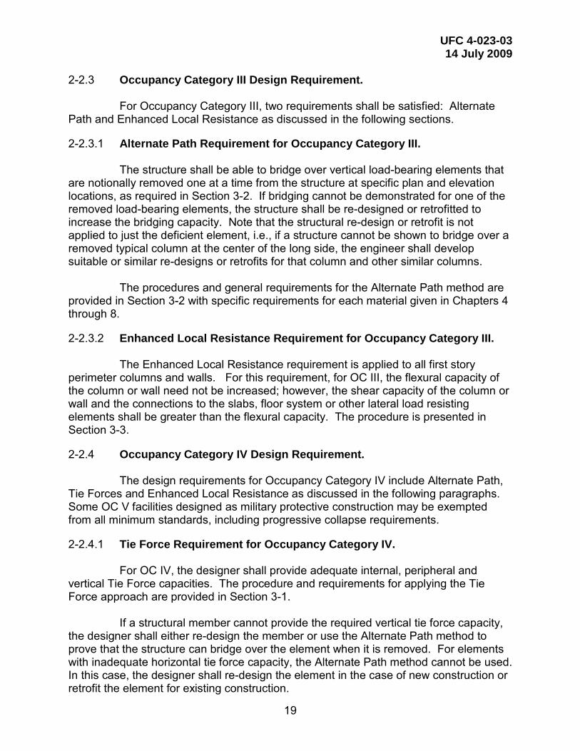
2-2.3 Occupancy Category III Design Requirement.
For Occupancy Category III, two requirements shall be satisfied: Alternate Path and Enhanced Local Resistance as discussed in the following sections.
2-2.3.1 Alternate Path Requirement for Occupancy Category III. The structure shall be able to bridge over vertical load-bearing elements that
are notionally removed one at a time from the structure at specific plan and elevation locations, as required in Section 3-2. If bridging cannot be demonstrated for one of the removed load-bearing elements, the structure shall be re-designed or retrofitted to increase the bridging capacity. Note that the structural re-design or retrofit is not applied to just the deficient element, i.e., if a structure cannot be shown to bridge over a removed typical column at the center of the long side, the engineer shall develop suitable or similar re-designs or retrofits for that column and other similar columns.
The procedures and general requirements for the Alternate Path method are
provided in Section 3-2 with specific requirements for each material given in Chapters 4 through 8.
2-2.3.2 Enhanced Local Resistance Requirement for Occupancy Category III.
The Enhanced Local Resistance requirement is applied to all first story perimeter columns and walls. For this requirement, for OC III, the flexural capacity of the column or wall need not be increased; however, the shear capacity of the column or wall and the connections to the slabs, floor system or other lateral load resisting elements shall be greater than the flexural capacity. The procedure is presented in Section 3-3.
2-2.4 Occupancy Category IV Design Requirement.
The design requirements for Occupancy Category IV include Alternate Path, Tie Forces and Enhanced Local Resistance as discussed in the following paragraphs. Some OC V facilities designed as military protective construction may be exempted from all minimum standards, including progressive collapse requirements.
2-2.4.1 Tie Force Requirement for Occupancy Category IV. For OC IV, the designer shall provide adequate internal, peripheral and
vertical Tie Force capacities. The procedure and requirements for applying the Tie Force approach are provided in Section 3-1.
If a structural member cannot provide the required vertical tie force capacity,
the designer shall either re-design the member or use the Alternate Path method to prove that the structure can bridge over the element when it is removed. For elements with inadequate horizontal tie force capacity, the Alternate Path method cannot be used. In this case, the designer shall re-design the element in the case of new construction or retrofit the element for existing construction.
UFC 4-023-03 14 July 2009
20
2-2.4.2 Alternate Path Requirement for Occupancy Category IV. For OC IV, use the same AP requirement as for OC III; see Section 2-2.3.1.
2-2.4.3 Enhanced Local Resistance Requirement for Occupancy Category IV.
For the first two stories on the building perimeter, the flexural capacity of the columns and walls shall be increased by a factor of 2 and a factor of 1.5, respectively, over the design flexural strength determined from the Alternate Path procedure in Paragraph 2-2.4.2. The shear capacity of the column or wall and the connections to the slabs, floor system or other lateral load resisting elements shall be greater than the flexural capacity. Procedures for Enhanced Local Resistance are given in Section 3-3.

UFC 4-023-03 14 July 2009
21
CHAPTER 3 DESIGN PROCEDURES
The progressive collapse design requirements employ three design/analysis
approaches: Tie Forces (TF), Alternate Path (AP), and Enhanced Local Resistance (ELR). This chapter discusses the required procedures for these approaches.
3-1 TIE FORCES.
In the Tie Force approach, the building is mechanically tied together, enhancing continuity, ductility, and development of alternate load paths. Tie forces can be provided by the existing structural elements that have been designed using conventional design methods to carry the standard loads imposed upon the structure.
There are three horizontal ties that must be provided: longitudinal,
transverse, and peripheral. Vertical ties are required in columns and load-bearing walls. Figure 3-1 illustrates these ties for frame construction. Note that these “tie forces” are different from “reinforcement ties” as defined in ACI 318 Building Code Requirements for Structural Concrete.
Unless the structural members (beams, girders, spandrels) and their
connections can be shown capable of carrying the required longitudinal, transverse, or peripheral tie force magnitudes while undergoing rotations of 0.20-rad (11.3-deg), the longitudinal, transverse, and peripheral tie forces are to be carried by the floor and roof system. Acceptable floor and roof systems include cast-in-place concrete, composite decks, and precast concrete floor planks with concrete topping, reinforcement, and mechanical anchorage that meet the requirements of Sections 3-1.2 and 3-1.3. Other floor or roof systems may be used, provided that the ability to carry the required tie strength while undergoing rotations of 0.20-rad (11.3-deg) is adequately demonstrated to and approved by an independent third-party engineer or by an authorized representative of the facility owner.
3-1.1 Load and Resistance Factor Design for Tie Forces.
Following the Load and Resistance Factor Design (LRFD) approach, the design tie strength is taken as the product of the strength reduction factor, Φ, and the nominal tie strength Rn calculated in accordance with the requirements and assumptions of applicable material specific codes. Include any over-strength factors provided in Chapters 5 to 7 of ASCE 41, where these over-strength factors are referred to as “factors to translate lower bound material properties to expected strength material properties” and are given in Tables 5-3 (structural steel), 6-4 (reinforced concrete), and 7-2 (masonry). For wood and cold-formed steel, Chapter 8 of ASCE 41 provides default expected strength values; note that for wood construction, a time effect factor λ is also included. Per the LRFD approach, the design tie strength must be greater than or equal to the required tie strength:

UFC 4-023-03 14 July 2009
22
Φ Rn ≥ Σ γi Qi Equation (3-1) where Φ Rn = Design Tie Strength Φ = Strength reduction factor Rn = Nominal Tie Strength calculated with the
appropriate material specific code, including the over-strength factors from Chapters 5 to 8 of ASCE 41.
Σγi Qi = Required Tie Strength γi = Load factor
Qi = Load Effect The required tie strengths are provided in the following sub-sections for
framed and load-bearing wall structures. While ASCE 41 requires that all Φ factors be taken as unity, this UFC
requires that strength reduction factors, Φ, be used as specified in the appropriate material specific code, for the action or limit state under consideration.
Figure 3-1. Tie Forces in a Frame Structure
Vertical Tie
Internal Longitudinal and Transverse Ties (dotted lines)
Peripheral Tie (dashed lines)

UFC 4-023-03 14 July 2009
23
3-1.2 Floor Loads.
3-1.2.1 Uniform Floor Load.
Use the floor load in Equation 3-2 to determine the required tie strengths: wF = 1.2D + 0.5L Equation (3-2) Where wF = Floor Load (lb/ft2 or kN/m2)
D = Dead Load (lb/ft2 or kN/m2) L = Live Load (lb/ft2 or kN/m2) If the Dead Load or Live Load vary over the plan of the floor, use the
procedure in Section 3-1.2.2 to determine the effective wF.
3-1.2.2 Consideration for Non-Uniform Load Over Floor Area.
3-1.2.2.1 Concentrated Loads.
If a concentrated load is located within a bay or one portion of the bay has a different loading than the rest of the bay, distribute the load evenly over the bay area and include in the dead or live load, as appropriate, in Equation 3-2.
3-1.2.2.2 Load Variations. The load magnitude may vary significantly over the plan area of a given story,
e.g. manufacturing activities may be located in one section of the floor and office space in another; see Figure 3-2. Calculate the floor load for each bay using Equation 3-2. Determine the effective floor load that will be used to determine the longitudinal, transverse, and peripheral Tie Forces, as follows:
1) If the difference between the minimum and maximum floor load in the bays
on the floor plan is less than or equal to 25% of the minimum floor load and the area associated with the maximum floor load is
a. Less than or equal to 25% of the total floor plan area, use an
effective wF, calculated by computing the total force acting on the floor and dividing by the total plan area.
b. Greater than 25% of the floor plan, use the maximum floor load as
the effective wF .
2) If the difference between the minimum and maximum floor load in the bays on the floor plan is greater than 25% of the minimum floor load, either:
a. Use the maximum floor load as the effective wF, or,

UFC 4-023-03 14 July 2009
24
b. Divide the floor plan into sub-areas, where a sub-area is a region composed of contiguous or adjacent bays that have the same floor load. Each sub-area shall have its own longitudinal and transverse ties and peripheral ties. In addition, a peripheral tie will be placed in the boundary between the sub-areas, as shown in Figure 3-2. The required strength of the peripheral tie between the sub-areas shall be equal to the sum of the required peripheral tie force on the heavily loaded sub-area and the required peripheral tie force on the lightly loaded sub-area. In this case, the internal ties are not required to be continuous from one side of the structure to the other but may be interrupted at the sub-area peripheral tie, providing that the internal ties from both sub-areas are properly anchored with seismic hooks to the sub-area peripheral tie. If desired, the longitudinal and transverse internal ties on the lightly loaded sub-area may be continued across the heavily loaded sub-area as part of the longitudinal and transverse internal ties of the heavily loaded side. Note that sufficient embedment or anchoring must be provided to develop the strength of all peripheral ties, at the sub-area boundary and at the exterior of the building.
c. Note that the peripheral tie between the sub-areas may be omitted if the transverse and longitudinal ties from the heavily loaded sub- area continue across the lightly loaded sub-area and are anchored to the exterior peripheral ties. For instance, in Figure 3-2, the longitudinal ties from the heavily loaded sub-area could extend the full length of the floor plan, the transverse ties from the heavily loaded sub-area in the three left bays could extend the full width of the floor plan and transverse ties from the lightly loaded sub-area in the right two bays could extend the full width of the floor plan.
3-1.2.3 Cladding and Façade Loads.
Cladding and façade loads are used for the calculation of the peripheral and vertical tie forces and are omitted for the transverse and longitudinal tie calculations.
3-1.3 Required Tie Strength, Distribution, and Location.
The required tie strength, distribution, and location for longitudinal, transverse, peripheral, and vertical ties are defined in the following sub-sections for framed and load-bearing wall structures.
The design tie strengths are considered separately from the forces that are
typically carried by each structural element due to live load, dead load, wind load, etc. In other words, the design tie strength of a slab, beam, column, rebar, or connection with no other loads acting must be greater than or equal to the required tie strength. In addition, the tie member itself, its splices and its connections only resist the calculated tensile forces. There are no structural strength or stiffness requirements to be applied to the structural members that are anchoring these horizontal tie forces.
UFC 4-023-03 14 July 2009
25
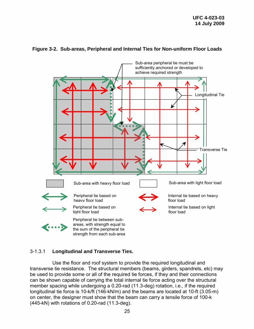
Figure 3-2. Sub-areas, Peripheral and Internal Ties for Non-uniform Floor Loads
3-1.3.1 Longitudinal and Transverse Ties.
Use the floor and roof system to provide the required longitudinal and transverse tie resistance. The structural members (beams, girders, spandrels, etc) may be used to provide some or all of the required tie forces, if they and their connections can be shown capable of carrying the total internal tie force acting over the structural member spacing while undergoing a 0.20-rad (11.3-deg) rotation, i.e., if the required longitudinal tie force is 10-k/ft (146-kN/m) and the beams are located at 10-ft (3.05-m) on center, the designer must show that the beam can carry a tensile force of 100-k (445-kN) with rotations of 0.20-rad (11.3-deg).
Sub-area with heavy floor load Sub-area with light floor load
Peripheral tie based on heavy floor load
Peripheral tie based on light floor load
Internal tie based on heavy floor load
Internal tie based on light floor load
Sub-area peripheral tie must be sufficiently anchored or developed to achieve required strength
Peripheral tie between sub-areas, with strength equal to the sum of the peripheral tie strength from each sub-area
Longitudinal Tie
Transverse Tie

UFC 4-023-03 14 July 2009
26
3-1.3.1.1 Framed Structures, Including Flat Plate and Flat Slab. Longitudinal and transverse tie forces shall be distributed orthogonally to
each other throughout the floor and roof system. The longitudinal and transverse ties must be anchored to peripheral ties at each end. Spacing must not be greater than 0.2 LT, or 0.2 LL where LT and LL are the greater of the distances between the centers of the columns, frames, or walls supporting any two adjacent floor spaces in the transverse and longitudinal directions, respectively.
For flat plate and flat slab structures without internal beams, girders, or
spandrels, place no more than twice the required tie strength (force per unit length) in the column area, which is the column strip 0.2 LL or 0.2 LT wide that is centered on the column lines and runs in the direction of the tie under consideration, as shown in Figure 3-3. For instance, if the required longitudinal tie force FL is 10-k/ft (146-kN/m), and LT is 20-ft (6.1-m), then the width of the column area is 0.2 LT or 4-ft (1.22-m) and the maximum total tie force allowed in the column area is 2 x 10-k/ft x 0.2 x 20-ft or 80-k (356-kN). The remainder of the required total tie force is distributed in the floor or roof system.
For framed buildings with internal beams, girders, or spandrels, internal ties
may cross over these elements, but are not to be placed parallel to these members and within the member or within the area directly above the member, unless the member can be shown capable of a 0.20-rad (11.3-deg) rotation. The internal ties that would fall within this area must be placed on either side of the beam, so that the total required tie strength for the adjacent bays is maintained. An illustration of this restriction is shown in Figure 3-4.
The required tie strength Fi (lb/ft or kN/m) in the longitudinal or transverse direction is
Fi = 3 wF L1 Equation (3-3) Where wF = Floor load, determined per Section 3-1.2, in
(lb/ft2 or kN/m2) L1 = Greater of the distances between the centers of the columns, frames, or walls supporting any two adjacent floor spaces in the direction under consideration (ft or m)
3-1.3.1.2 Load-bearing Wall Structures. A longitudinal and a transverse tie force shall be distributed orthogonally to
each other throughout the floor and roof system. These ties must be anchored to peripheral ties at each end.
For two-way spans, spacing must not be greater than 0.2 LT, or 0.2 LL where
LT and LL are the greatest of the distances between the centers of the walls supporting any two adjacent floor spaces in the transverse and longitudinal directions, respectively;

UFC 4-023-03 14 July 2009
27
see Figure 3-3. No more than twice the required tie strength shall be placed in the wall area, which is defined as the area bounded by the centers of the columns, frames, or walls supporting any two adjacent floor spaces in the direction of the tie under consideration and within 0.1 LT or 0.1 LL of the wall line, as appropriate, as shown in Figure 3-3. For two-way spans, the required tie strength Fi (lb/ft or kN/m) in the longitudinal or transverse direction is
Fi = 3 wF L1 Equation (3-4) Where wF = Floor load, determined per Section 3-1.2, (lb/ft2 or kN/m2) L1 = Greater of the distances between the centers of the columns, frames, or walls supporting any two adjacent floor spaces in the direction under consideration (ft or m) For one-way spans, spacing of the longitudinal and transverse ties must not
be greater than 0.2 LL, where LL is the greatest of the distances between the centers of the walls supporting any two adjacent floor spaces in the longitudinal direction; see Figure 3-5. A maximum of twice the required tie strength shall be placed in the wall area, which is defined as the area within 0.1 LL of the wall line, as shown in Figure 3-5. For one-way spans, LL is the greater of the distances between the centers of the wall in the one-way span direction, as shown in Figure 3-5. In the transverse direction LT is 5 hw, where hw is the clear story height. The required tie strength Fi (lb/ft or kN/m) in the longitudinal or transverse direction is
Fi = 3 wF L1 Equation (3-5) Where wF = Floor load, determined per Section 3-1.2, ((lb/ft2 or
kN/m2) L1 = either LL = the greater of the distances between the
centers of the walls supporting any two adjacent floor spaces in the longitudinal direction or LT = 5 hw, as appropriate (ft or m)
hw = Clear story height (ft or m)

UFC 4-023-03 14 July 2009
28
Figure 3-3. Determination of L1 and Column Area for Frame and Two-way Span Load-bearing Wall Construction
Figure 3-4. Location Restrictions for Internal and Peripheral Ties that are Parallel
to the Long Axis of a Beam, Girder or Spandrel
Longitudinal Direction, L1 = LL = 30-ft (9.1-m)
20-ft (6.1-m) 30-ft (9.1-m)
< 0.2 LT
Spacing < 0.2 LT
Column or Wall Area
Transverse Direction, L1 = LT = 20-ft (6.1-m)
< 0.2 LL
Spacing < 0.2 LL
Longitudinal
Transverse
Column or Wall Area
Internal ties allowed Internal ties
allowed
Peripheral ties allowed within 1-m of shaded area
Internal ties allowed
Peripheral ties allowed within 1-m of shaded area
1-m 1-m
20-ft (6.1-m)
20-ft (6.1-m)
20-ft (6.1-m)
20-ft (6.1-m)
30-ft (9.1-m)
Ties not allowed in shaded area unless beam is capable of providing a 0.20-rad rotation
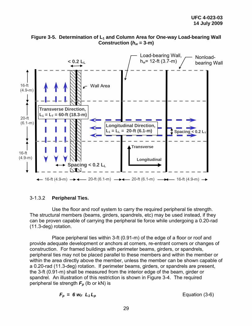
UFC 4-023-03 14 July 2009
29
Figure 3-5. Determination of L1 and Column Area for One-way Load-bearing Wall Construction (hw = 3-m)
3-1.3.2 Peripheral Ties. Use the floor and roof system to carry the required peripheral tie strength.
The structural members (beams, girders, spandrels, etc) may be used instead, if they can be proven capable of carrying the peripheral tie force while undergoing a 0.20-rad (11.3-deg) rotation.
Place peripheral ties within 3-ft (0.91-m) of the edge of a floor or roof and
provide adequate development or anchors at corners, re-entrant corners or changes of construction. For framed buildings with perimeter beams, girders, or spandrels, peripheral ties may not be placed parallel to these members and within the member or within the area directly above the member, unless the member can be shown capable of a 0.20-rad (11.3-deg) rotation. If perimeter beams, girders, or spandrels are present, the 3-ft (0.91-m) shall be measured from the interior edge of the beam, girder or spandrel. An illustration of this restriction is shown in Figure 3-4. The required peripheral tie strength Fp (lb or kN) is
Fp = 6 wF L1 Lp Equation (3-6)
20-ft (6.1-m)
Load-bearing Wall, hw= 12-ft (3.7-m)
Spacing < 0.2 LL
Nonload-bearing Wall
Transverse Direction, L1 = LT = 60-ft (18.3-m)
Longitudinal Direction, L1 = LL = 20-ft (6.1-m)
16-ft (4.9-m)
Spacing < 0.2 LT
< 0.2 LL
Wall Area
Longitudinal
Transverse
20-ft (6.1-m) 20-ft (6.1-m) 16-ft (4.9-m)
16-ft (4.9-m)
16-ft (4.9-m)

UFC 4-023-03 14 July 2009
30
Where wF = Floor load, determined per Section 3-1.2, (lb/ft2 or kN/m2) L1 = For exterior peripheral ties distances between the centers of the columns,
, the greater of the
frames, or walls at the perimeter of the building in the direction under consideration (m or ft).
For peripheral ties at openings (see Figure 3-6),
length of the bay in which the opening is located, in the
the direction under consideration. Lp = 3-ft (0.91-m)
Note that the dead load includes the self weight of the members, superimposed dead loads and any cladding or façade loads (if the cladding and façade loads are directly supported by the structure or floor or roof system). If a cladding or façade dead load is given in force per unit length along the perimeter, it shall be converted to a pressure loading by uniformly distributing it over the 3-ft (0.91-m) wide peripheral tie strip and then added to the other dead loads.
For buildings with one- and two-story sections attached to a section with three
or more stories, peripheral ties shall be placed in any contiguous floors at the boundary between the short and tall sections.
3-1.3.3 Vertical Ties. Use the columns and load-bearing walls to carry the required vertical tie
strength. Each column and load-bearing wall shall be tied continuously from the foundation to the roof level
The vertical tie must have a design strength in tension equal to the largest vertical load received by the column or wall from any one story, using the tributary area and the floor load wF as determined in Section 3-1.2.
3-1.4 Continuity of Ties. The load path for peripheral ties must be continuous around the plan
geometry. For internal longitudinal and transverse ties, the path must be continuous from one edge to the other. However, interruptions due to courtyards, mezzanines, elevator/stairwell cores, etc, are allowed, as shown in Figure 3-6, when a peripheral tie is placed at the interruption. Insure that sufficient embedment or anchoring is provided to develop the strength of the peripheral ties placed at the interruption; anchor the longitudinal and transverse ties to the peripheral ties with seismic hooks. Along a particular load path, different structural elements may be used to provide the required tie strength, providing that they are adequately connected.
Each column and load-bearing wall shall be tied continuously from the
foundation to the roof level.
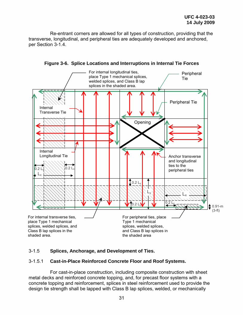
UFC 4-023-03 14 July 2009
31
Re-entrant corners are allowed for all types of construction, providing that the transverse, longitudinal, and peripheral ties are adequately developed and anchored, per Section 3-1.4.
Figure 3-6. Splice Locations and Interruptions in Internal Tie Forces
3-1.5 Splices, Anchorage, and Development of Ties.
3-1.5.1 Cast-in-Place Reinforced Concrete Floor and Roof Systems. For cast-in-place construction, including composite construction with sheet
metal decks and reinforced concrete topping, and, for precast floor systems with a concrete topping and reinforcement, splices in steel reinforcement used to provide the design tie strength shall be lapped with Class B lap splices, welded, or mechanically
For internal transverse ties, place Type 1 mechanical splices, welded splices, and Class B lap splices in the shaded area.
0.2 Ly
0.2 Ly
0.2 Lx
Peripheral Tie
Peripheral Tie
Anchor transverse and longitudinal ties to the peripheral ties
For peripheral ties, place Type 1 mechanical splices, welded splices, and Class B lap splices in the shaded area
Lx
0.2 Lx 0.91-m (3-ft)
Opening
0.2 Lx
For internal longitudinal ties, place Type 1 mechanical splices, welded splices, and Class B lap splices in the shaded area.
Internal Longitudinal Tie
Internal Transverse Tie
Lx
Ly

UFC 4-023-03 14 July 2009
32
joined with Type 1 or Type 2 mechanical splices, per ACI 318. Splices shall be staggered within the allowable shaded areas shown in Figure 3-6.
Type 2 mechanical splices may be used at any location in the slab. For
internal longitudinal and transverse ties, Type 1 mechanical splices, welded splices, and Class B lap splices shall be located no closer than 20% of the bay spacing in the direction of the tie to any vertical-load carrying elements (i.e., these splices must be within the middle 60% of the slab or floor or roof system bay, in the direction of the tie); see Figure 3-6. For peripheral ties, Type 1 mechanical splices, welded splices, and Class B lap splices shall be placed no closer than 20% of the span distance in the peripheral tie direction; see Figure 3-6. Note that noncontact splices are not allowed.
Use seismic hooks as defined in ACI 318 to anchor and connect ties to other ties. Use seismic development lengths for joints of special moment frames as defined in ACI 318 to develop the peripheral ties. At re-entrant corners or at substantial changes in construction, take care to insure that the transverse, longitudinal, and peripheral ties are adequately anchored and developed.
3-1.5.2 Precast Concrete Floor and Roof Systems.
For precast concrete floor and roof systems, the rebar within the precast planks may be used to provide the internal tie forces, providing the rebar is continuous across the structure and properly anchored; this may be difficult to accomplish in the short direction of the plank. Also, the rebar may be placed within a concrete topping; in this case, provide positive mechanical engagement between the reinforcement and the precast floor system, with sufficient strength to insure that the precast units do not separate from the topping and fall to the space below. Do not rely on the bond strength between the topping and precast units, as the bond can be disrupted by the large deformations associated with catenary behavior. This attachment between the rebar in the concrete topping and the precast planks may be accomplished with hooks, loops or other mechanical attachments that are embedded in the precast floor units.
3-1.5.3 Composite Construction Floor and Roof Systems. If composite construction with steel decks and concrete topping is employed,
provide sufficient connection between the steel beam and the composite floor such that the beam will not fall to the space below.
3-1.5.4 Other Floor and Roof Systems and Structural Elements.
If other floor and roof systems and structural elements can be shown capable of carrying the tie forces required in Sections 3-1.3.1 and 3-1.3.2 while undergoing a rotation of 0.20-rad (11.3-deg) and while meeting the continuity requirement of Section 3-1.5, provide adequate splicing and anchorage that allows development of the transverse, longitudinal, and peripheral tie forces required in Section 3-1.3.

UFC 4-023-03 14 July 2009
33
3-1.6 Structural Elements and Connections With Inadequate Tie Strength
If the vertical design tie strength of any structural element or connection is less than the vertical required tie strength, the designer must either: 1) revise the design to meet the tie force requirements or 2) use the Alternate Path method to prove that the structure is capable of bridging over this deficient element.
The AP method shall not be applied to structural elements or connections that
cannot provide the required longitudinal, transverse, or peripheral tie strength; in this case, the designer must redesign or retrofit the element and connection such that a sufficient design tie strength is developed.
3-2 ALTERNATE PATH METHOD.
The Alternate Path method is used in two situations: 1) for Option 1 of Occupancy Category II and for Occupancy Category IV, when a vertical structural element cannot provide the required tie strength, the designer may use the AP method to determine if the structure can bridge over the deficient element after it has been notionally removed, and 2) for Occupancy Category II Option 2, Occupancy Category III, and Occupancy Category IV, the AP method must be applied for the removal of specific vertical load-bearing elements which are prescribed in Section 3-2.9.
3-2.1 General.
This method follows the LRFD philosophy by employing the ASCE 7 load factor combination for extraordinary events and resistance factors to define design strengths. Three analysis procedures are employed: Linear Static (LSP), Nonlinear Static (NSP) and Nonlinear Dynamic (NDP). These procedures follow the general approach in ASCE 41 with modifications to accommodate the particular issues associated with progressive collapse. Much of the material-specific criteria from Chapters 5 to 8 of ASCE 41 are explicitly adopted in Chapters 4 to 8 of this document. The topics of each ASCE 41 Chapter are:
• Steel or cast iron, ASCE 41 Chapter 5. • Reinforced concrete, ASCE 41 Chapter 6. • Reinforced or un-reinforced masonry, ASCE 41 Chapter 7. • Timber, light metal studs, gypsum, or plaster products, ASCE 41 Chapter 8.
Note that some of the deformation and strength criteria in ASCE 41 Chapters 5 to 8 have been superseded by requirements that are specified in the material specific Chapters 4 to 8 in this UFC.
3-2.2 Alternative Rational Analysis.
For the performance of the Alternate Path analysis and design, nothing in this document shall be interpreted as preventing the use of any alternative analysis

UFC 4-023-03 14 July 2009
34
procedure that is rational and based on fundamental principles of engineering mechanics and dynamics. For example, simplified analytical methods employing hand calculations or spreadsheets may be appropriate and more efficient for some types of buildings, such as load-bearing wall structures.
The results of any alternative rational analyses shall meet the acceptance
criteria contained in this document in Section 3-2.10 and in Chapters 4 through 8. The analyses shall include the specified locations for removal of columns and load-bearing walls in Section 3-2.9 and the ASCE 7 extreme event load combination, with the load increase factors in Sections 3-2.11.5 and 3-2.12.5 for linear static and nonlinear static analyses, respectively. The designer shall verify that these criteria are applicable to the alternative rational analyses. If a Linear Static approach is employed, the requirements of Section 3-2.11.1 must be met. All projects using alternative rational analysis procedures shall be reviewed and approved by an independent third-party engineer or by an authorized representative of the facility owner.
3-2.3 Load and Resistance Factor Design for Alternate Path Method.
Following the LRFD approach, the Design Strength provided by a member and its connections to other members in terms of flexure, axial load, shear and torsion is taken as the product of the strength reduction factor Φ and the nominal strength Rn calculated in accordance with the requirements and assumptions of applicable material specific codes. Include any over-strength factors provided in Chapters 5 to 7 of ASCE 41, where these over-strength factors are referred to as “factors to translate lower bound material properties to expected strength material properties” and are given in Tables 5-3 (structural steel), 6-4 (reinforced concrete), and 7-2 (masonry). For wood and cold-formed steel, Chapter 8 of ASCE 41 provides default expected strength values; note that for wood construction, a time effect factor λ is also included. Per the LRFD approach, the design strength must be greater than or equal to the required strength:
Φ Rn ≥ Σ γi Qi Equation (3-7) where Φ Rn = Design Strength Φ = Strength reduction factor Rn = Nominal Strength calculated per Chapters 4 to 8 of this UFC, including over- strength factor Ω where applicable.
Σγi Qi = Required Strength γi = Load factor
Qi = Load Effect
While ASCE 41 requires that all Φ factors be taken as unity, this UFC requires that strength reduction factors, Φ, be used as specified in the appropriate material specific code, for the action or limit state under consideration.

UFC 4-023-03 14 July 2009
35
Note that live load reductions per ASCE 7 are permitted for all live loads used in Alternate Path analysis and design.
3-2.4 Primary and Secondary Components. Designate all structural elements and components as either primary or
secondary. Classify structural elements and components that provide the capacity of the structure to resist collapse due to removal of a vertical load-bearing element as primary. Classify all other elements and components as secondary. For example, a steel gravity beam may be classified as secondary if it is assumed to be pinned at both ends and the designer chooses to ignore any flexural strength at the connection; if the connection is modeled as partially restrained and thus contributes to the resistance of collapse, it is a primary member.
3-2.5 Force-and Deformation-Controlled Actions.
Classify all actions as either deformation-controlled or force-controlled using the component force versus deformation curve shown in Figure 3-7. Examples of deformation- and force-controlled actions are listed in Table 3-1. Note that a component might have both force- and deformation-controlled actions. Further, classification as a force- or deformation-controlled action is not up to the discretion of the user and must follow the guidance presented here.
Define a primary component action as deformation-controlled if it has a Type
1 curve and e ≥ 2g, or, it has a Type 2 curve and e ≥ 2g. Define a primary component action as force-controlled if it has a Type 1 or Type 2 curve and e < 2g, or, if it has a Type 3 curve.
Define a secondary component action as deformation-controlled if it has a
Type 1 curve for any e/g ratio or if it has a Type 2 curve and e ≥ 2g. Define a secondary component action as force controlled if it has a Type 2 curve and e < 2g, or, if it has a Type 3 curve.
Figure 3-7. Definition of Force-Controlled and Deformation-Controlled Actions, from ASCE 41
c
3
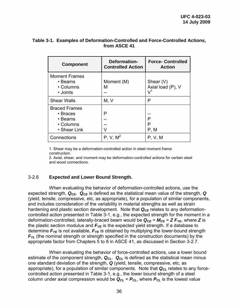
UFC 4-023-03 14 July 2009
36
Table 3-1. Examples of Deformation-Controlled and Force-Controlled Actions,
from ASCE 41
Component Deformation- Controlled Action
Force- Controlled Action
Moment Frames • Beams • Columns • Joints
Moment (M) M --
Shear (V) Axial load (P), V V1
Shear Walls M, V P Braced Frames
• Braces • Beams • Columns • Shear Link
P -- -- V
-- P P P, M
Connections P, V, M2 P, V, M
1. Shear may be a deformation-controlled action in steel moment frame construction. 2. Axial, shear, and moment may be deformation-controlled actions for certain steel and wood connections.
3-2.6 Expected and Lower Bound Strength.
When evaluating the behavior of deformation-controlled actions, use the expected strength, QCE. QCE is defined as the statistical mean value of the strength, Q (yield, tensile, compressive, etc, as appropriate), for a population of similar components, and includes consideration of the variability in material strengths as well as strain hardening and plastic section development. Note that QCE relates to any deformation-controlled action presented in Table 3-1, e.g., the expected strength for the moment in a deformation-controlled, laterally-braced beam would be QCE = MCE = Z FYE, where Z is the plastic section modulus and FYE is the expected yield strength. If a database to determine FYE is not available, FYE is obtained by multiplying the lower-bound strength FYL (the nominal strength or strength specified in the construction documents) by the appropriate factor from Chapters 5 to 8 in ASCE 41, as discussed in Section 3-2.7.
When evaluating the behavior of force-controlled actions, use a lower bound
estimate of the component strength, QCL. QCL is defined as the statistical mean minus one standard deviation of the strength, Q (yield, tensile, compressive, etc, as appropriate), for a population of similar components. Note that QCL relates to any force-controlled action presented in Table 3-1, e.g., the lower bound strength of a steel column under axial compression would be QCL = PCL, where PCL is the lowest value

UFC 4-023-03 14 July 2009
37
obtained for the limit states of column buckling, local flange buckling, or local web buckling, calculated with the lower bound strength, FYL. Where data to determine the lower bound strength are not available, use the nominal strength or strength specified in the construction documents.
3-2.7 Material Properties.
Expected material properties such as yield strength, ultimate strength, weld strength, fracture toughness, elongation, etc, shall be based on mean values of tested material properties. Lower bound material properties shall be based on mean values of tested material properties minus one standard deviation.
If data to determine the lower bound and expected material properties do not
exist, use nominal material properties, or properties specified in construction documents, as the lower bound material properties unless otherwise specified in Chapters 5 through 8 of ASCE 41. Calculate the corresponding expected material properties by multiplying lower bound values by appropriate factors specified in Chapters 5 through 8 of ASCE 41 to translate from lower bound material properties to expected material values. If factors for converting from an expected to lower bound material property are not specified, use the lower bound material property as the expected material property.
3-2.8 Component Force and Deformation Capacities.
Detailed methods for calculation of individual component force and deformation capacities shall comply with the requirements in the individual ASCE 41 material chapters.
In calculating QCE and QCL, use the appropriate strength reduction factor for each action, as specified in the material specific design codes (i.e., the Φ factors in ACI 318, the AISC Steel Construction Manual, etc). Note that Φ factors are not included in the component capacity calculations defined in Chapters 5 through 8 of ASCE 41.
3-2.8.1 Component Capacities for Nonlinear Procedures. For nonlinear procedures, component capacities for deformation-controlled
actions shall be taken as permissible inelastic deformation limits, and component capacities for force-controlled actions shall be taken as lower-bound strengths, QCL, multiplied by the appropriate strength reduction factor Φ, as summarized in Table 3-2.

UFC 4-023-03 14 July 2009
38
Table 3-2. Calculation of Component Action Capacity for Nonlinear Static and Nonlinear Dynamic Procedures, from ASCE 41
Parameter Deformation-Controlled Force-Controlled
Deformation Capacity, New and Existing Component
Deformation limit N/A
Strength Capacity, New and Existing Component N/A Φ QCL
3-2.8.2 Component Capacities for the Linear Static Procedure.
For the linear static procedure, capacities for deformation-controlled actions shall be defined as the product of m-factors and expected strengths, QCE, multiplied by the appropriate strength reduction factor Φ. Capacities for force-controlled actions shall be defined as lower-bound strengths, QCL, multiplied by the appropriate strength reduction factor Φ, as summarized in Table 3-3.
Table 3-3. Calculation of Component Action Capacity for the Linear Static
Procedure, from ASCE 41
Parameter Deformation-Controlled Force-Controlled
New and Existing Material Strength
Expected material strength
Specified material strength
New and Existing Action Capacity Φ QCE Φ QCL

UFC 4-023-03 14 July 2009
39
3-2.9 Removal of Load-Bearing Elements for the Alternate Path Method.
Load-bearing elements are removed for the following two cases:
1) For OC II Option 1 and OC IV structures, where an element cannot provide the required vertical tie strength,
2) For OC II Option 2, OC III, and OC IV structures, where AP is applied to elements for which the location and size are specified to verify that the structure has adequate flexural resistance to bridge over the missing element.
For both external and internal column removal, for the purposes of AP
analysis, beam-to-beam continuity is assumed to be maintained across a removed column; see Figure 3-7.
The details of the size and location of the removed load-bearing elements are
described in the following sub-paragraphs.
Figure 3-8. Removal of Column from Alternate Path Model

UFC 4-023-03 14 July 2009
40
3-2.9.1 Extent of Removed Load-Bearing Elements.
3-2.9.1.1 OC II Option 1 (Deficient Vertical Tie Force). For each column that cannot provide the required vertical tie force, remove
the clear height between lateral restraints. For each load-bearing wall that cannot provide the required vertical tie force,
the length of the removed section of wall is twice the clear story height H, if the length of the deficient wall is greater than 2H. If the length of the deficient wall is less than 2H, remove just that portion of deficient wall. In both instances, remove the clear height between lateral restraints. Note that discontinuities, such as joints, segmented walls, or openings for doors or windows, can be located within the 2H length, providing that the loads above that discontinuity are carried by the remainder of the wall in the 2H length.
3-2.9.1.2 OC II Option 2, OC III, and OC IV
For each column, remove the clear height between lateral restraints. For each load-bearing wall, remove a length that is twice the clear story
height H. Remove the clear height between lateral restraints. Note that only planar sections of wall are removed, i.e., if a shear wall has a C-shaped cross-section in plan, only the flange or only the web are removed, but not both. However, for external corners, where one or both of the intersecting walls is load bearing, remove a length of wall equal to the clear story height H in each direction
3-2.9.2 Location of Removed Load-Bearing Elements.
3-2.9.2.1 OC II Option 1 (Deficient Vertical Tie Force). Remove the column that cannot provide the required vertical tie force. For a deficient load-bearing wall or section thereof that is longer than 2H,
determine the location(s) for removal by using the guidance for wall removal locations provided in Sections 3-2.9.2.4 and 3-2.9.2.5. Additionally, use engineering judgment to shift the location of the removed 2H section of wall within the length of deficient wall to evaluate worse case scenarios. If the length of the deficient load-bearing wall is less than 2H, remove just the section that is deficient.
3-2.9.2.2 OC II Option 2, OC III and IV External Columns.
For OC II Option 2, OC III and OC IV, as a minimum, remove external columns near the middle of the short side, near the middle of the long side, and at the corner of the building, as shown in Figure 3-9. Also remove columns at locations where the plan geometry of the structure changes significantly, such as abrupt decrease in bay size or re-entrant corners, or, at locations where adjacent columns are lightly loaded,

UFC 4-023-03 14 July 2009
41
the bays have different tributary sizes, and members frame in at different orientations or elevations. Use engineering judgment to recognize these critical column locations.
For each plan location defined for element removal, perform AP analyses for:
1. First story above grade 2. Story directly below roof 3. Story at mid-height 4. Story above the location of a column splice or change in column size
For example, if a corner column is specified as the removed element location
in a ten story building with a column splice at the third story, one AP analysis is performed for removal of the ground story corner column; another AP analysis is performed for the removal of the corner column at the tenth story; another AP analysis is performed for the fifth story corner column (mid-height story) and one AP analysis is performed for the fourth story corner column (story above the column splice).
3-2.9.2.3 OC II Option 2, OC III and OC IV Internal Columns.
For OC II Option 2, OC III and OC IV structures with underground parking or other areas of uncontrolled public access, remove internal columns near the middle of the short side, near the middle of the long side and at the corner of the uncontrolled space, as shown in Figure 3-10. The removed column extends from the floor of the underground parking area or uncontrolled public floor area to the next floor (i.e., a one story height must be removed). Internal columns must also be removed at other critical locations within the uncontrolled public access area, as determined with engineering judgment. For each plan location, the AP analysis is only performed for the story with the parking or uncontrolled public area.
3-2.9.2.4 OC II Option 2, OC III and OC IV External Load-Bearing Walls.
As a minimum, remove external load-bearing walls near the middle of the short side, near the middle of the long side and at the corner of the building, as shown in Figure 3-11. For external corners, where one or both of the intersecting walls is load bearing, remove a length of wall equal to the clear story height H in each direction. Also remove load-bearing walls at locations where the plan geometry of the structure changes significantly, such as at an abrupt decrease in bay size or at re-entrant corners, as well as at locations where adjacent walls are lightly loaded, the bays have different sizes, and members frame in at different orientations or elevations. Use engineering judgment to recognize these critical locations. The length of the removed wall section is specified in Section 3-2.9.1. The designer must use engineering judgment to shift the location of the removed wall section by a maximum of the clear story height H if that creates a worst case scenario.
For each plan location defined for element removal, perform AP analyses for
the following stories:
1. First story above grade

UFC 4-023-03 14 July 2009
42
2. Story directly below roof 3. Story at mid-height 4. Story above the location of a change in wall size
For example, if a wall section at the middle of the long side is specified as the
removed element location in a six story wood building with a change in wall framing at the third story, one AP analysis is performed for removal of the ground story wall section; another AP analysis is performed for the removal of the wall section at the sixth story; another AP analysis is performed for the third story (mid-height story) and one AP analysis is performed for the fourth story (story above the change in wall framing).
3-2.9.2.5 OC II Option 2, OC III and OC IV Internal Load-Bearing Walls.
For structures with underground parking or other areas of uncontrolled public access, remove internal load-bearing walls near the middle of the short side, near the middle of the long side and at the corner of the uncontrolled space, as shown in Figure 3-12. For internal corners, where one or both of the intersecting walls is load-bearing, remove a length of wall equal to the clear story height H in each direction. The removed wall extends from the floor of the underground parking area or uncontrolled public floor area to the next floor (i.e., a one story height must be removed). Also remove internal load-bearing walls at other critical locations within the uncontrolled public access area, as determined with engineering judgment. For each plan location, the AP analyses are only performed for the load-bearing walls at the story with parking area or uncontrolled public space, and not for all stories in the structure. The length of the removed wall section is specified in Section 3-2.9.1. The designer must use engineering judgment to shift the location of the removed wall section by a maximum of the wall height if that creates a worst case scenario.
3-2.10 Structure Acceptance Criteria.
For all three analysis types (LS, NS, and ND), the building is structurally adequate if none of the primary and secondary elements, components, or connections exceeds the acceptance criteria, in Paragraphs 3-2.11.7, 3-2.12.7, and 3-2.13.6, as appropriate. If the analysis predicts that any element, component, or connection does not meet these acceptance criteria, the building does not satisfy the progressive collapse requirements and must be re-designed or retrofitted.

UFC 4-023-03 14 July 2009
43
Figure 3-9. Location of External Column Removal for OC III and IV Structures
Figure 3-10. Location of Internal Column Removal for OC III and IV Structures
PUBLIC ACCESS SPACES (HATCHED AREA)

UFC 4-023-03 14 July 2009
44
Figure 3-11. Location of External Load-Bearing Wall Removal for OC III and OC IV
Structures
Figure 3-12. Location of Internal Load-Bearing Wall Removal for OC III and OC IV Structures

UFC 4-023-03 14 July 2009
45
3-2.11 Linear Static Procedure.
The LSP and limitations to its use are provided in the following sub-sections.
3-2.11.1 Limitations on the Use of LSP. The use of the LSP is limited to structures that meet the following
requirements for irregularities and Demand-Capacity Ratios (DCRs). If there are no structural irregularities as defined in Section 3-2.11.1.1, a
linear static procedure may be performed and it is not necessary to calculate the DCRs defined in Section 3-2.11.1.2. If the structure is irregular, a linear static procedure may be performed if all of the component DCRs determined in the Section 3-2.11.1.1 are less than or equal to 2.0. If the structure is irregular and one or more of the DCRs exceed 2.0, then a linear static procedure cannot be used.
3-2.11.1.1 Irregularity Limitations. A structure is considered irregular if any one of the following is true:
1. Significant discontinuities exist in the gravity-load carrying and lateral force-resisting systems of a building, including out-of-plane offsets of primary vertical elements, roof “belt-girders”, and transfer girders (i.e., non-stacking primary columns or load-bearing elements). Stepped back stories are not considered an irregularity.
2. At any exterior column except at the corners, at each story in a framed structure, the ratios of bay stiffness and/or strength from one side of the column to the other are less than 50%. Three examples are; a) the lengths of adjacent bays vary significantly, b) the beams on either side of the column vary significantly in depth and/or strength, and c) connection strength and/or stiffness vary significantly on either side of the column (e.g., for a steel frame building, a shear tab connection on one side of a column and a fully rigid connection on the other side shall be considered irregular).
3. For all external load-bearing walls, except at the corners, and for each story in a load-bearing wall structure, the ratios of wall stiffness and/or strength from one side of an intersecting wall to the other are less than 50%.
4. The vertical lateral-load resisting elements are not parallel to the major orthogonal axes of the lateral force-resisting system, such as the case of skewed or curved moment frames and load-bearing walls.
3-2.11.1.2 DCR Limitation. To calculate the DCRs for either framed or load-bearing structures, create a
linear model of the building as described in Section 3-2.11.2.1. The model will have all

UFC 4-023-03 14 July 2009
46
primary components with the exception of the removed wall or column. The deformation-controlled load case in Section 3-2.11.4.1 shall be applied, with gravity dead and live loads increased by the load increase factor ΩLD in Section 3-2.11.5. The resulting actions (internal forces and moments) are defined as QUDLim:
Use QUDLim to calculate the DCRs for the deformation controlled actions as:
DCR = QUDLim/QCE Equation (3-8) where QCE = Expected strength of the component or element, as specified in Chapters 4 to 8.
3-2.11.2 Analytical Modeling.
To model, analyze, and evaluate a building, employ a three-dimensional assembly of elements and components. Two-dimensional models are not permitted.
3-2.11.2.1 Loads.
Analyze the model with two separate load cases: 1) to calculate the deformation-controlled actions QUD, and 2) to calculate the force-controlled actions QUF. Apply the Lateral Loads and Gravity loads to the model using the load cases for deformation-controlled actions and force-controlled actions defined in Section 3-2.11.4.
3-2.11.2.2 Required Model Elements.
Include the stiffness and resistance of only the primary elements and components. Insure that the model includes a sufficient amount of structural detail to allow the correct transfer of vertical loads from the floor and roof system to the primary elements. Use the guidance of ASCE 41 Chapters 5 through 8 to create the model. Also, as discussed later, and after the analysis is performed, check the primary and secondary elements against the acceptance criteria for force-controlled and deformation-controlled actions. While secondary elements are not included in the model, their actions and deformations can either be estimated based on the deformations of the model with only primary elements or the model may be re-analyzed with the secondary components included. If the model is re-analyzed with the secondary components included, their stiffness and resistance must be set to zero, i.e., the advantage of including the secondary components is that the analyst may more easily check the secondary elements deformations rather than perform hand calculations of the original model.
If the building contains sections that are less than three stories and are
attached to the sections with three or more stories, the designer shall perform an analysis to determine whether there is a possibility that the presence of the short section will affect the taller section in a negative manner; if so, then include the short section in the model.

UFC 4-023-03 14 July 2009
47
3-2.11.2.3 Limitations on Connection Strength.
For models that incorporate connections between horizontal flexural elements (beams, slabs, girders, etc) and vertical load-bearing elements (columns and walls), the strength of the connection shall not be modeled as greater than the strength of the attached horizontal flexural element.
3-2.11.3 Lateral Stability/P-Δ Effects.
Lateral stability and P-Δ effects are included through the provisions of lateral loading in the load combination defined and discussed in Section 3-2.11.4.
3-2.11.4 Loading. Due to the different methods by which deformation-controlled and force-
controlled actions are calculated, two load cases will be applied and analyzed: one for the deformation-controlled actions, and one for the force-controlled actions, as specified here.
3-2.11.4.1 Load Case for Deformation-Controlled Actions QUD.
To calculate the deformation-controlled actions, simultaneously apply the following combination of gravity and lateral loads:
Increased Gravity Loads for Floor Areas Above Removed Column or Wall.
Apply the following increased gravity load combination to those bays immediately adjacent to the removed element and at all floors above the removed element; see Figures 3-13 and 3-14.
GLD = ΩLD [(0.9 or 1.2) D + (0.5 L or 0.2 S)] Equation (3-9) where GLD = Increased gravity loads for deformation- controlled actions for Linear Static Analysis D = Dead load including façade loads (lb/ft2 or kN/m2) L = Live load including live load reduction per ASCE 7
(lb/ft2 or kN/m2) S = Snow load (lb/ft2 or kN/m2) ΩLD = Load increase factor for calculating deformation- controlled actions for Linear Static analysis; use appropriate value for framed or load-bearing wall structures; see Section 3-2.11.5
Gravity Loads for Floor Areas Away From Removed Column or Wall
. Apply the following gravity load combination to those bays not loaded with GLD; see Figures 3-13 and 3-14.
G = (0.9 or 1.2) D + (0.5 L or 0.2 S) Equation (3-10)
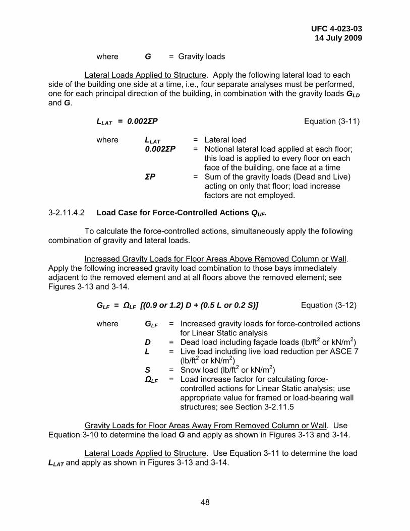
UFC 4-023-03 14 July 2009
48
where G = Gravity loads Lateral Loads Applied to Structure
. Apply the following lateral load to each side of the building one side at a time, i.e., four separate analyses must be performed, one for each principal direction of the building, in combination with the gravity loads GLD and G.
LLAT = 0.002ΣP Equation (3-11) where LLAT = Lateral load 0.002ΣP = Notional lateral load applied at each floor; this load is applied to every floor on each face of the building, one face at a time ΣP = Sum of the gravity loads (Dead and Live) acting on only that floor; load increase
factors are not employed.
3-2.11.4.2 Load Case for Force-Controlled Actions QUF.
To calculate the force-controlled actions, simultaneously apply the following combination of gravity and lateral loads.
Increased Gravity Loads for Floor Areas Above Removed Column or Wall
. Apply the following increased gravity load combination to those bays immediately adjacent to the removed element and at all floors above the removed element; see Figures 3-13 and 3-14.
GLF = ΩLF [(0.9 or 1.2) D + (0.5 L or 0.2 S)] Equation (3-12) where GLF = Increased gravity loads for force-controlled actions
for Linear Static analysis D = Dead load including façade loads (lb/ft2 or kN/m2) L = Live load including live load reduction per ASCE 7 (lb/ft2 or kN/m2) S = Snow load (lb/ft2 or kN/m2) ΩLF = Load increase factor for calculating force- controlled actions for Linear Static analysis; use appropriate value for framed or load-bearing wall structures; see Section 3-2.11.5
Gravity Loads for Floor Areas Away From Removed Column or Wall
. Use Equation 3-10 to determine the load G and apply as shown in Figures 3-13 and 3-14.
Lateral Loads Applied to Structure
. Use Equation 3-11 to determine the load LLAT and apply as shown in Figures 3-13 and 3-14.
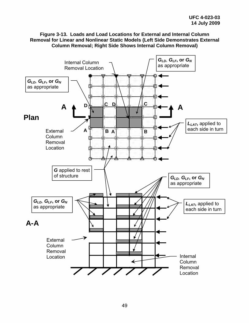
UFC 4-023-03 14 July 2009
49
Figure 3-13. Loads and Load Locations for External and Internal Column Removal for Linear and Nonlinear Static Models (Left Side Demonstrates External
Column Removal; Right Side Shows Internal Column Removal)
External Column Removal Location
A-A
Internal Column Removal Location
External Column Removal Location
Plan A A
GLD, GLF, or GN as appropriate
G applied to rest of structure
Internal Column Removal Location
GLD, GLF, or GN as appropriate
GLD, GLF, or GN as appropriate
GLD, GLF, or GN as appropriate
LLAT, applied to each side in turn
LLAT, applied to each side in turn
B A
C D
A B
C D

UFC 4-023-03 14 July 2009
50
Figure 3-14. Loads and Load Locations for External and Internal Wall Removal for Linear and Nonlinear Static Models (Left Side Demonstrates External Wall
Removal; Right Side Shows Internal Wall Removal)
A
D
B
C D
A B
C
External Wall Removal Location
A A
Internal Wall Removal Location
Plan
Internal Wall Removal Location
External Wall Removal Location
A-A
GLD, GLF, or GN as appropriate
GLD, GLF, or GN as appropriate
G applied to rest of structure GLD, GLF, or GN
as appropriate
GLD, GLF, or GN as appropriate
LLAT, applied to each side in turn
LLAT, applied to each side in turn

UFC 4-023-03 14 July 2009
51
3-2.11.5 Load Increase Factor.
The load increase factors for deformation-controlled and force-controlled actions for column and wall removal are provided in Table 3-4.
In Table 3-4, mLIF is the smallest m of any primary beam, girder, spandrel or
wall element that is directly connected to the columns or walls directly above the column or wall removal location. For each primary beam, girder, spandrel or wall element, m is the m-factor defined in Chapters 4 to 8 of this UFC, where m is either explicitly provided in each chapter or reference is made to ASCE 41 and a corresponding performance level (Collapse Prevention or Life Safety). Columns are omitted from the determination of mLIF. The method behind this procedure is explained in Appendix C.
Table 3-4. Load Increase Factors for Linear Static Analysis
Material Structure Type ΩLD,
Deformation-controlled
ΩLF, Force-
controlled
Steel Framed 0.9 mLIF + 1.1 2.0
Reinforced Concrete FramedA 1.2 mLIF + 0.80 2.0
Load-bearing Wall 2.0 mLIF 2.0
Masonry Load-bearing Wall 2.0 mLIF 2.0
Wood Load-bearing Wall 2.0 mLIF 2.0
Cold-formed Steel Load-bearing Wall 2.0 mLIF 2.0 A Note that, per ASCE 41, reinforced concrete beam-column joints are treated as force-controlled; however, the hinges that form in the beam near the column are deformation-controlled and the appropriate m-factor from Chapter 4 of this UFC shall be applied to the calculation of the deformation-controlled load increase factor ΩLD.
3-2.11.6 Design Forces and Deformations.
Calculate the deformation-controlled actions QUD, and force-controlled actions QUF, accordance with the linear analysis procedures of Sections 3-2.11.2 to 3-2.11.5.

UFC 4-023-03 14 July 2009
52
3-2.11.7 Component and Element Acceptance Criteria.
Components and elements analyzed using the linear procedures of Section 3-2.11.2 to 3-2.11.5 shall satisfy the requirements of this section. Prior to selecting component acceptance criteria, classify components as primary or secondary, and classify actions as deformation-controlled or force-controlled, as defined in Section 3-2.5.
3-2.11.7.1 Deformation-Controlled Actions.
For deformation-controlled actions in all primary and secondary components, check that: Φ m QCE ≥ QUD Equation (3-13) where QUD = Deformation-controlled action, from Linear Static model m = Component or element demand modifier (m-factor) as defined in Chapters 4 to 8 of this document. Φ = Strength reduction factor from the appropriate material specific code.
QCE = Expected strength of the component or element for deformation-controlled actions.
QCE, the expected strength, shall be determined by considering all coexisting
actions on the component under the design loading condition by procedures specified in ASCE 41 Chapters 5 through 8. Note that this includes interaction equations for shear, axial force, and moment and that these equations include force- and deformation-controlled actions, as well as expected and lower bound strengths.
Use the appropriate resistance factor for each action, as specified in the
material specific design codes (i.e., the Φ factors in ACI 318, the AISC Steel Construction Manual, etc).
3-2.11.7.2 Force-Controlled Actions.
For force-controlled actions in all primary and secondary components, Φ QCL ≥ QUF Equation (3-14) where QUF = Force-controlled action, from Linear Static model
QCL = Lower-bound strength of a component or element for force-controlled actions
Φ = Strength reduction factor from the appropriate material specific code.
UFC 4-023-03 14 July 2009
53
QCL, the lower-bound strength, shall be determined by considering all coexisting actions on the component under the design loading condition by procedures specified in ASCE 41 Chapters 5 through 8. Use the appropriate resistance factor for each action, as specified in the material specific design codes (i.e., the Φ factors in ACI 318, the AISC Steel Construction Manual, etc).
3-2.11.7.3 Secondary Elements and Components.
All secondary components and elements must be checked to ensure that they meet the acceptance criteria. This can either be done directly for each component or element where displacements are known, or alternately, a second mathematical model can be constructed that includes the secondary components. If the model is re-analyzed with the secondary components included, their stiffness and resistance must be set to zero, i.e., the advantage of including the secondary components is that the analyst may more easily check the secondary elements deformations rather than perform hand calculations of the original model. All deformation-controlled actions are then checked according to Equation 3-13 and all force-controlled actions are then checked according to Equation 3-14. Note that in lieu of checking Equation 3-13, the secondary deformation-controlled actions may be checked against the expected nonlinear deformation capacities, per Section 3-2.12.7.1; see Appendix E for an example of this procedure.
3-2.12 Nonlinear Static Procedure. The NSP and limitations to its use are provided in the following sub-sections.
3-2.12.1 Limitations on the Use of NSP. There are no DCR or geometric irregularity limitations on the use of the NSP.
3-2.12.2 Analytical Modeling.
To model, analyze, and evaluate a building, employ a three-dimensional assembly of elements and components. Two-dimensional models are not permitted. Create one model, as shown in Figures 3-13 and 3-14 for either framed or load-bearing wall structures, respectively. Inclusion of secondary components in the model is optional. However, if the secondary components are omitted, they must be checked after the analysis, against the allowable deformation-controlled criteria (e.g., to check the connections of gravity beams in a steel structure, compute the chord rotation and compare against the allowable plastic rotation angle for that connection). Include the stiffness and resistance of primary components. Note that the strength reduction factors are applied to the nonlinear strength models of the deformation controlled components (e.g., the nominal flexural strength of a beam or connection is multiplied by the appropriate Φ factor). Analyze the model for the Nonlinear Static load case defined in Section 3-2.12.4
Use the stiffness requirements of ASCE 41 Chapters 5 through 8 to create
the model. Discretize the load-deformation response of each component along its

UFC 4-023-03 14 July 2009
54
length to identify locations of inelastic action. The force-displacement behavior of all components shall be explicitly modeled, including strength degradation and residual strength, if any. Model a connection explicitly if the connection is weaker or has less ductility than the connected components, or the flexibility of the connection results in a change in the connection forces or deformations greater than 10%.
If the building contains sections that are less than three stories and are
attached to the sections with three or more stories, the designer shall use engineering judgment to include some or all of the shorter section if there is any possibility that the presence of the short section will affect the taller section in a negative manner.
3-2.12.3 Lateral Stability/P-Δ Effects.
Lateral stability and P-Δ effects are included through the provisions of lateral loading in the load combination defined and discussed in Section 3-2.12.4.
3-2.12.4 Loading.
3-2.12.4.1 Loads. To calculate the deformation-controlled and force-controlled actions,
simultaneously apply the following combination of gravity and lateral loads: Increased Gravity Loads for Floor Areas Above Removed Column or Wall
. Apply the following increased gravity load combination to those bays immediately adjacent to the removed element and at all floors above the removed element; see Figures 3-13 and 3-14.
GN = ΩN [(0.9 or 1.2) D + (0.5 L or 0.2 S)] Equation (3-15) where GN = Increased gravity loads for Nonlinear Static Analysis D = Dead load including façade loads (lb/ft2 or kN/m2) L = Live load including live load reduction per ASCE 7
(lb/ft2 or kN/m2) S = Snow load (lb/ft2 or kN/m2) ΩN = Dynamic increase factor for calculating deformation-controlled and force-controlled actions
for Nonlinear Static analysis; use appropriate value for framed or load-bearing wall structures; see Section 3-2.12.5
Gravity Loads for Floor Areas Away From Removed Column or Wall
. Apply the following gravity load combination to those bays not loaded with GN; see Figures 3-13 and 3-14.
G = (0.9 or 1.2) D + (0.5 L or 0.2 S) Equation (3-16)

UFC 4-023-03 14 July 2009
55
where G = Gravity loads Lateral Loads Applied to Structure
. Apply the following lateral load to each side of the building, one side at a time, i.e., four separate analyses must be performed, one for each principal direction of the building, in combination with the increased gravity loads GN and G.
LLAT = 0.002ΣP Equation (3-17) where LLAT = Lateral load 0.002ΣP = Notional lateral load applied at each floor; this load is applied to every floor on each face of the building, one face at a time (i.e., four load combinations must be assessed for a rectangular building) ΣP = Sum of the gravity loads (Dead and Live) acting on only that floor; dynamic increase factors are not employed.
3-2.12.4.2 Loading Procedure.
Apply the loads using a load history that starts at zero and is increased to the final values. Apply at least 10 load steps to reach the total load. The software must be capable of incrementally increasing the load and iteratively reaching convergence before proceeding to the next load increment.
3-2.12.5 Dynamic Increase Factor for NSP.
The Nonlinear Static dynamic increase factors are provided in Table 3-5. In Table 3-5, θpra is the plastic rotation angle given in the acceptance criteria
tables in ASCE 41 and this UFC for the appropriate structural response level (Collapse Prevention or Life Safety, as specified in Chapters 4 to 8 of this UFC) for the particular element, component or connection; θy is the yield rotation. For steel, θy is given in Equation 5-1 in ASCE 41. For reinforced concrete, θy is determined with the effective stiffness values provided in Table 6-5 in ASCE 41. Note that for connections, θy is the yield rotation angle of the structural element that is being connected (beam, slab, etc) and θpra is for the connection (determined from ASCE 41 and this UFC). Columns are omitted from the determination of the DIF.
To determine the DIF for the analysis of the entire structure, choose the
smallest ratio of θpra/θy for any primary element, component, or connection in the model within or touching the area that is loaded with the increased gravity load, as shown in Figures 3-13 and 3-14. In other words, the DIF for every primary connection, beam, girder, wall element, etc that falls within or touches the perimeter marked as A-B-C-D must be determined and the largest value is used for the analysis. The method behind this procedure is explained in Appendix C.

UFC 4-023-03 14 July 2009
56
Table 3-5. Dynamic Increase Factors for Nonlinear Static Analysis
Material Structure Type ΩN
Steel Framed 1.08 + 0.76/(θpra/θy + 0.83)
Reinforced Concrete Framed 1.04 + 0.45/(θpra/θy + 0.48)
Load-Bearing Wall 2
Masonry Load-bearing Wall 2
Wood Load-bearing Wall 2
Cold-formed Steel Load-bearing Wall 2
3-2.12.6 Design Forces and Deformations.
Calculate component design forces and deformations in accordance with the nonlinear analysis procedure of Sections 3-2.12.2 to 3-2.12.5.
3-2.12.7 Component and Element Acceptance Criteria.
Components and elements analyzed using the nonlinear procedures of Sections 3-2.12.2 to 3-2.12.5 shall satisfy the requirements of this section.
3-2.12.7.1 Deformation-Controlled Actions.
Primary and secondary elements and components shall have expected deformation capacities greater than the maximum calculated deformation demands. Expected deformation capacities shall be determined considering all coexisting forces and deformations in accordance with Chapters 4 to 8 of this document.
3-2.12.7.2 Force-Controlled Actions.
For force-controlled actions in all primary and secondary elements and components, Φ QCL ≥ QUF Equation (3-18) where QUF = Force-controlled action, from Nonlinear Static model
QCL = Lower-bound strength of a component or element. Φ = Strength reduction factor from the appropriate material specific code.

UFC 4-023-03 14 July 2009
57
QCL, the lower-bound strength, shall be determined by considering all coexisting actions on the component under the design loading condition by procedures specified in ASCE 41 Chapters 5 through 8. Use the appropriate resistance factor for each action, as specified in the material specific design codes (i.e., the Φ factors in ACI 318, the AISC Steel Construction Manual, etc).
3-2.13 Nonlinear Dynamic Procedure.
The NDP and limitations to its use are provided in the following sub-sections.
3-2.13.1 Limitations on the Use of NDP. There are no DCR or geometric irregularity limitations on the use of the NDP.
3-2.13.2 Analytical Modeling.
To model, analyze, and evaluate a building, employ a three-dimensional assembly of elements and components. Two-dimensional models are not permitted. Create a model of the entire structure, including the wall section and column that are to be removed during the analysis. Include the stiffness and resistance of primary components. Note that the strength reduction factors are applied to the nonlinear strength models of the deformation controlled components (e.g., the nominal flexural strength of a beam or connection is multiplied by the appropriate Φ factor). Inclusion of secondary components in the model is optional. However, if the secondary components are omitted, they must be checked after the analysis, against the allowable deformation-controlled criteria (e.g., to check the connections of gravity beams in a steel structure, compute the chord rotation and compare against the allowable plastic rotation angle for that connection). Apply the loads and analyze the model per the loading procedure in Section 3-2.13.4.
Use the stiffness requirements of ASCE 41 Chapters 5 through 8 to create
the model. Discretize the load-deformation response of each component along its length to identify locations of inelastic action. The force-displacement behavior of all components shall be explicitly modeled, including strength degradation and residual strength, if any. Model a connection explicitly if the connection is weaker or has less ductility than the connected components, or the flexibility of the connection results in a change in the connection forces or deformations greater than 10%.
If the building contains sections that are less than three stories and are
attached to the sections with three or more stories, the designer shall use engineering judgment to include some or all of the shorter section if there is any possibility that the presence of the short section will affect the taller section in a negative manner.
3-2.13.3 Lateral Stability and P- Δ Effects.
Lateral stability and P-Δ effects are included through the provisions of lateral loading in the load combination defined and discussed in Section 3-2.13.4.

UFC 4-023-03 14 July 2009
58
3-2.13.4 Loading.
3-2.13.4.1 Loads. To calculate the deformation-controlled and force-controlled actions, apply the
following combination of gravity and lateral loads per the loading procedure given in Section 3-2.13.4.2:
Gravity Loads for Entire Structure
. Apply the following gravity load combination to the entire structure.
GND = (0.9 or 1.2) D + (0.5 L or 0.2 S) Equation (3-19) where GND = Gravity loads for Nonlinear Dynamic Analysis D = Dead load including façade loads (lb/ft2 or kN/m2) L = Live load including live load reduction per ASCE 7
(lb/ft2 or kN/m2) S = Snow load (lb/ft2 or kN/m2)
Lateral Loads Applied to Structure Side
. Apply the following lateral load to each side of the building one side at a time, i.e., four separate analyses must be performed, one for each principal direction of the building, in combination with the gravity load GND.
LLAT = 0.002ΣP Equation (3-20) where LLAT = Lateral load 0.002ΣP = Notional lateral load applied at each floor; this load is applied to every floor on each face of the building, one face at a time (i.e., four load combinations must be assessed for a rectangular building) ΣP = Sum of the gravity loads (Dead and Live) acting on only that floor
3-2.13.4.2 Loading Procedure. Starting at zero load, monotonically and proportionately increase the gravity
loads and lateral loads to the entire model (i.e., the column or wall section have not been removed yet) until equilibrium is reached.
After equilibrium is reached for the framed and load-bearing wall structures,
remove the column or wall section. While it is preferable to remove the column or wall section instantaneously, the duration for removal must be less than one tenth of the period associated with the structural response mode for the vertical motion of the bays above the removed column, as determined from the analytical model with the column or wall section removed. The analysis shall continue until the maximum displacement is
UFC 4-023-03 14 July 2009
59
reached or one cycle of vertical motion occurs at the column or wall section removal location.
3-2.13.5 Design Forces and Deformations.
Calculate component design forces and deformations in accordance with the nonlinear analysis procedure of Sections 3-2.13.2 to 3-2.13.4.
3-2.13.6 Component and Element Acceptance Criteria.
Components and elements analyzed using the nonlinear procedures of Sections 3-2.13.2 to 3-2.13.4 shall satisfy the requirements of this section.
3-2.13.6.1 Deformation-Controlled Actions.
Primary and secondary elements and components shall have expected deformation capacities greater than the maximum calculated deformation demands. Expected deformation capacities shall be determined considering all coexisting forces and deformations in accordance with Chapters 4 to 8 of this document.
3-2.13.6.2 Force-Controlled Actions.
For force-controlled actions in all primary and secondary components, Φ QCL ≥ QUF Equation (3-20) where QUF = Force-controlled action, from Nonlinear Dynamic model
QCL = Lower-bound strength of a component or element. Φ = Strength reduction factor from the appropriate material specific code.
QCL, the lower-bound strength, shall be determined by considering all
coexisting actions on the component under the design loading condition by procedures specified in ASCE 41 Chapters 5 through 8. Use the appropriate resistance factor for each action, as specified in the material specific design codes (i.e., the Φ factors in ACI 318, the AISC Steel Construction Manual, etc).
3-3 ENHANCED LOCAL RESISTANCE.
Enhanced Local Resistance (ELR) is required in three cases: OC II Option 1 (Tie Forces and ELR), OC III (Alternate Path and ELR), and OC IV (Tie Forces, Alternate Path and ELR). ELR is provided through the prescribed flexural and shear resistance of perimeter building columns and load bearing walls, as described in the following paragraphs

UFC 4-023-03 14 July 2009
60
3-3.1 ELR Location Requirements.
3-3.1.1 OC II Option 1.
For OC II Option 1, ELR is applied to the perimeter corner and penultimate columns and load-bearing walls of the first story above grade.
3-3.1.2 OC III.
For OC III, ELR is applied to all perimeter columns and load-bearing walls of the first story above grade.
3-3.1.3 OC IV.
For OC IV, ELR is applied to all perimeter columns and load-bearing walls of the first two stories above grade.
3-3.2 Flexural Resistance Calculation.
The flexural resistance is defined as the magnitude of a uniform load acting over the height of the wall or load-bearing column which causes flexural failure, i.e. the formation of a three hinge mechanism or similar failure mode. In calculating the flexural resistance, consider any effects (axial load, compression membrane behavior, end conditions, etc) that may act to increase the flexural resistance; in no case shall the flexural resistance be less than that of the column or wall with zero axial load acting. Resistance calculations shall include any applicable material over-strength factors. Do not apply strength reduction factors, Φ. The flexural resistance shall be determined for the horizontal out-of-plane direction (i.e., perpendicular to the building perimeter façade). Columns at building corners or re-entrant corners shall be evaluated in both directions normal to the building perimeter façade.
3-3.3 Flexural and Shear Resistance.
3-3.3.1 OC II Option 1.
3-3.3.1.1 OC II Option 1 Baseline Flexural Resistance.
For OC II Option 1, the baseline flexural resistance is based on the existing or as-designed columns and load-bearing walls. Apply the procedure in Paragraph 3-3.2 to these columns and walls to determine the baseline flexural resistance.
3-3.3.1.2 OC II Option 1 Shear Resistance. The shear resistance of the column, load-bearing wall, and their connections
must be equal to or greater than the shear capacity associated with the baseline flexural resistance, i.e., application of the uniform load that defines the baseline flexural resistance must not fail the column, load-bearing wall or their connections and splices (if applicable) in shear. Check the shear resistance of the columns and walls and re-

UFC 4-023-03 14 July 2009
61
design if necessary to match the shear capacity associated with the baseline flexural resistance. Check and, if necessary, design the connections between the columns and walls and the lateral force resisting system (base plates, floor, diaphragm, beam, girder, etc) to transfer the reactions calculated with the baseline flexural resistance. Insure that the lateral force resisting system can resist the reactions from each column and walls, taken one at a time.
3-3.3.2 OC III.
3-3.3.2.1 OC III Baseline Flexural Resistance. For OC III, an existing or new building must first meet the Alternate Path
requirement and the resulting design is then used to determine the baseline flexural resistance. Apply the procedure in Paragraph 3-3.2 to determine the baseline flexural resistance.
3-3.3.2.2 OC III Shear Resistance. The shear resistance of the column, load-bearing wall, and their connections
must be equal to or greater than the shear capacity associated with the baseline flexural resistance, as for OC II Option 1. Apply the requirements in Paragraph 3-3.3.1.2.
3-3.3.3 OC IV.
3-3.3.3.1 OC IV Enhanced Flexural Resistance.
For OC IV, two flexural resistances must be calculated and compared to determine the enhanced flexural resistance. First, the baseline flexural resistance is calculated using the design of the structure when only gravity loads are considered. If such a design or analysis was not performed during the initial design and analysis of the new or existing structure, it must be performed to determine the column and load-bearing wall design. The gravity loads-only design is then used to determine the baseline flexural resistance per the procedure in Paragraph 3-3.2.
Second, the existing flexural resistance is calculated using the column and
load-bearing wall design determined after the Alternate Path procedure was applied to the structural design that incorporated all applied loads (wind, earthquake, gravity, etc.). Use the procedure defined in Paragraph 3-3.2.
For columns in OC IV structures, the enhanced flexural resistance is the
larger of the existing flexural resistance or 2.0 times the baseline flexural resistance. If the enhanced flexural resistance is greater than the existing flexural resistance, re-design the column to match the enhanced flexural resistance load.
For load-bearing walls in OC IV structures, the enhanced flexural resistance
is the larger of the existing flexural resistance or 1.5 times the baseline flexural resistance. If the enhanced flexural resistance is greater than the existing flexural

UFC 4-023-03 14 July 2009
62
resistance, re-design the load-bearing wall to match the enhanced flexural resistance load.
3-3.3.3.2 OC IV Shear Resistance. The shear resistance of the column, load-bearing wall and their connections
must be equal to or greater than the shear capacity associated with the enhanced flexural resistance, as for OC II Option 1. Apply the requirements in Paragraph 3-3.3.1.2.

UFC 4-023-03 14 July 2009
63
CHAPTER 4 REINFORCED CONCRETE
This chapter provides the specific requirements for designing a reinforced concrete building to resist progressive collapse. Appendix D demonstrates the application of the reinforced concrete design requirements for a 7-story building.
If composite construction with other materials is employed, use the design
guidance from the appropriate material chapter in this UFC for those structural elements or portions of the structure.
Note that the combination of design requirements (TF, AP, and ELR) will
depend upon the Occupancy Category of the buildings, as defined in Section 2-2.
4-1 MATERIAL PROPERTIES FOR REINFORCED CONCRETE.
Apply the appropriate over-strength factors to the calculation of the design strengths for both Tie Forces and the Alternate Path method. The over-strength factors are provided in ASCE 41 in Table 6-4 Factors to Translate Lower-Bound Material Properties to Expected Strength Material Properties.
4-2 STRENGTH REDUCTION FACTOR Φ FOR REINFORCED CONCRETE. For the Alternate Path and Tie Force methods, use the appropriate strength
reduction factor specified in ACI 318 Building Code Requirements for Structural Concrete for the component and behavior under consideration.
4-3 TIE FORCE REQUIREMENTS FOR REINFORCED CONCRETE.
Apply the Tie Force requirements in Section 3-1, when applicable, for concrete frame and load-bearing wall structural systems, mixed systems with concrete elements, and framed and load-bearing wall systems with precast concrete floors
The strength reduction factor Φ for properly anchored, embedded, or spliced
steel reinforcement in tension shall be taken as 0.75. The structural integrity requirements of ACI 318 for cast-in-place and precast
concrete construction must be satisfied, as well as the Tie Force requirements in this document. Use the largest or most stringent requirement when there is overlap between ACI 318 and this UFC.
4-4 ALTERNATE PATH REQUIREMENTS FOR REINFORCED CONCRETE.
4-4.1 General. Use the Alternate Path method in Section 3-2 to verify that the structure can
bridge over removed elements.

UFC 4-023-03 14 July 2009
64
4-4.2 Flexural Members and Joints.
For new and existing construction, the design strength and rotational capacities of the beams and beam-to-column joints shall be determined with the guidance found in ASCE 41, as modified with the acceptance criteria provided in Paragraph 4-4.3.
4-4.3 Modeling and Acceptance Criteria for Reinforced Concrete.
With the exception of Tables 6-7, 6-11, 6-14, and 6-15 in ASCE 41, use the modeling parameters, nonlinear acceptance criteria and linear m-factors for the Life Safety condition from Chapter 6 of ASCE 41 for primary and secondary components. Use the ASCE 41 modeling parameters and guidance, including definitions of stiffness, to create the analytical model.
Replace Table 6-7 of ASCE 41 with Table 4-1, which contains the nonlinear
modeling parameters and acceptance criteria for reinforced concrete beams. Replace Table 6-11 of ASCE 41 with Table 4-2, which contains the acceptance criteria for linear modeling of reinforced concrete beams.
Replace Table 6-14 of ASCE 41 with Table 4-3, which contains the nonlinear
modeling parameters and acceptance criteria for two-way slabs and slab-column connections. Replace Table 6-15 of ASCE 41 with Table 4-4, which contains the acceptance criteria for linear modeling of two-way slabs and slab-column connections.
4-5 ENHANCED LOCAL RESISTANCE REQUIREMENTS FOR REINFORCED CONCRETE.
Apply the Enhanced Local Resistance requirements in Section 3-3, where
applicable, for framed and load-bearing wall reinforced concrete buildings.

UFC 4-023-03 14 July 2009
65
Table 4-1. Nonlinear Modeling Parameters and Acceptance Criteria for Reinforced Concrete Beams (Replacement for Table 6-7 in ASCE 41)
Conditions
Modeling Parameters1 Acceptance Criteria1,2
Plastic Rotations Angle, radians
Residual Strength
Ratio
Plastic Rotations Angle, radians
Component Type
Primary Secondary
a b c
i. Beams controlled by flexure3
balρρρ '− Trans.
Reinf.4 cw fdbV
'
≤ 0.0 C ≤ 3 0.063 0.10 0.2 0.063 0.10
≤ 0.0 C ≥ 6 0.05 0.08 0.2 0.05 0.08
≥ 0.5 C ≤ 3 0.05 0.06 0.2 0.05 0.06
≥ 0.5 C ≥ 6 0.038 0.04 0.2 0.038 0.04
≤ 0.0 NC ≤ 3 0.05 0.06 0.2 0.05 0.06
≤ 0.0 NC ≥ 6 0.025 0.03 0.2 0.025 0.03
≥ 0.5 NC ≤ 3 0.025 0.03 0.2 0.025 0.03
≥ 0.5 NC ≥ 6 0.013 0.02 0.2 0.013 0.02
ii. Beams controlled by shear3
Stirrup spacing ≤ d /2 0.0030 0.02 0.2 0.002 0.01
Stirrup spacing > d /2 0.0030 0.01 0.2 0.002 0.005
iii. Beams controlled by inadequate development or splicing along the span3
Stirrup spacing ≤ d /2 0.0030 0.02 0.0 0.002 0.01
Stirrup spacing > d /2 0.0030 0.01 0.0 0.002 0.005
iv. Beams controlled by inadequate embedment into beam-column joint3 0.015 0.03 0.2 0.01 0.02
1. Linear interpolation between values listed in the table shall be permitted. See Section 3-2.4 for definition of primary and secondary components and Figure 3-6 for definition of nonlinear modeling parameters a, b, and c
2. Primary and secondary component demands shall be within secondary component acceptance criteria where the full backbone curve is explicitly modeled including strength degradation and residual strength, in accordance with Section 3.4.3.2 of ASCE 41.
3. Where more than one of the conditions i, ii, iii, and iv occurs for a given component, use the minimum appropriate numerical value from the table. 4. "C" and "NC" are abbreviations for conforming and nonconforming transverse reinforcement. A component is conforming if, within the flexural plastic
hinge region, hoops are spaced at ≤ d/3, and if, for components of moderate and high ductility demand, the strength provided by the hoops (Vs) is at least three-fourths of the design shear. Otherwise, the component is considered nonconforming..

UFC 4-023-03 14 July 2009
66
Table 4-2. Acceptance Criteria for Linear Models of Reinforced Concrete Beams (Replacement for Table 6-11 in ASCE 41)
Conditions
m-factors1
Component Type
Primary Secondary
i. Beams controlled by flexure2
balρρρ '− Trans.
Reinf.3 cw fdbV
' 4
≤ 0.0 C ≤ 3 16 19 ≤ 0.0 C ≥6 9 9 ≥ 0.5 C ≤ 3 9 9 ≥ 0.5 C ≥ 6 6 7 ≤ 0.0 NC ≤ 3 9 9 ≤ 0.0 NC ≥ 6 6 7 ≥ 0.5 NC ≤ 3 6 7 ≥ 0.5 NC ≥ 6 4 5
ii. Beams controlled by shear2 Stirrup spacing ≤ d /2 1.5 3 Stirrup spacing > d /2 1.5 2 iii. Beams controlled by inadequate development or splicing along the span2 Stirrup spacing ≤ d /2 1.5 3 Stirrup spacing > d /2 1.5 2 iv. Beams controlled by inadequate embedment into beam-column joint2 2 3 1. Linear interpolation between values listed in the table shall be permitted. See Section 3-2.4 for definition of primary and secondary
components.
2. Where more than one of the conditions i, ii, iii, and iv occurs for a given component, use the minimum appropriate numerical value from the table.
3. "C" and "NC" are abbreviations for conforming and nonconforming transverse reinforcement. A component is conforming if, within the flexural plastic hinge region, hoops are spaced at ≤ d/3, and if, for components of moderate and high ductility demand, the strength provided by the hoops (Vs) is at least three-fourths of the design shear. Otherwise, the component is considered nonconforming.
4. V is the design shear force calculated using limit-state analysis procedures in accordance with Section 6.4.2.4.1 of ASCE 41.

UFC 4-023-03 14 July 2009
67
Table 4-3. Modeling Parameters and Acceptance Criteria for Nonlinear Models of Two-Way Slabs and Slab-Column Connections (Replacement for Table 6-14 in
ASCE 41)
Conditions
Modeling Parameters1 Acceptance Criteria1,2
Plastic Rotations Angle, radians
Residual Strength
Ratio
Plastic Rotations Angle, radians
Component Type
Primary Secondary
a b c
i. Slabs controlled by flexure, and slab-column connections3
o
g
VV 2 Continuity
Reinforcement3
≤ 0.2 Yes 0.05 0.10 0.2 0.05 0.10
≥ 0.4 Yes 0.0 0.04 0.2 0.0 0.08
≤ 0.2 No 0.02 0.02 - 0.015 0.015
≥ 0.4 No 0.0 0.0 - 0.0 0.0
ii. Slabs controlled by inadequate development or splicing along the span3
0.0 0.02 0.0 0.0 0.01
iii. Slabs controlled by inadequate embedment into slab-column joint3
0.015 0.03 0.2 0.01 0.02
1. Linear interpolation between values listed in the table shall be permitted. See Section 3-2.4 for definition of primary and secondary components and Figure 3-6 for definition of nonlinear modeling parameters a, b, and c.
2. Primary and secondary component demands shall be within secondary component acceptance criteria where the full backbone curve is explicitly modeled including strength degradation and residual strength, in accordance with Section 3.4.3.2 of ASCE 41.
3. Where more than one of the conditions i, ii, iii, and iv occurs for a given component, use the minimum appropriate numerical value from the table.
4. Vg = the gravity shear acting on the slab critical section as defined by ACI 318; Vo = the direct punching shear strength as defined by ACI 318.
5. Under the heading “Continuity Reinforcement,” use “Yes” where at least one of the main bottom bars in each direction is effectively continuous through the column cage. Where the slab is post-tensioned, use “Yes” where at least one of the post-tensioning tendons in each direction passes through the column cage. Otherwise, use “No.”

UFC 4-023-03 14 July 2009
68
Table 4-4. Acceptance Criteria for Linear Models of Two-Way Slabs and Slab-Column Connections (Replacement for Table 6-15 in ASCE 41)
m-factors1
Conditions
Component Type
Primary Secondary
i. Slabs controlled by flexure, and slab-column connections2
o
g
VV 3 Continuity
Reinforcement4
≤ 0.2 Yes 6 7 ≥ 0.4 Yes 1 5 ≤ 0.2 No 2 2 ≥ 0.4 No 1 1
ii. Slabs controlled by inadequate development or splicing along the span2 - 4 iii. Slabs controlled by inadequate embedment into slab-column joint2 3 4
1. Linear interpolation between values listed in the table shall be permitted. See Section 3-2.4 for definition of primary and secondary components.
2. Where more than one of the conditions i, ii, and iii occurs for a given component, use the minimum appropriate numerical value from the table.
3. Vg = the gravity shear acting on the slab critical section as defined by ACI 318; Vo = the direct punching shear strength as defined by ACI 318.
4. Under the heading "Continuity Reinforcement," use "Yes" where at least one of the main bottom bars in each direction is effectively continuous through the column cage. Where the slab is post-tensioned, use "Yes" where at least one of the post-tensioning tendons in each direction passes through the column cage. Otherwise, use "No."

UFC 4-023-03 14 July 2009
69
CHAPTER 5 STRUCTURAL STEEL
This chapter provides the specific requirements for designing a structural steel building to resist progressive collapse. Appendix E demonstrates the application of the structural steel design requirements for a 4-story building.
If composite construction with other materials is employed, use the design
guidance from the appropriate material chapter in this UFC for those structural elements or portions of the structure.
Note that the combination of design requirements (TF, AP, and ELR) will
depend upon the Occupancy Category of the buildings, as defined in Section 2-2.
5-1 MATERIAL PROPERTIES FOR STRUCTURAL STEEL.
Apply the appropriate over-strength factors to the calculation of the design strengths for both Tie Forces and the Alternate Path method. The over-strength factors are provided in ASCE 41 in Table 5-3 Factors to Translate Lower-Bound Steel Properties to Expected Strength Steel Properties.
5-2 STRENGTH REDUCTION FACTOR Φ FOR STRUCTURAL STEEL. For Alternate Path and Tie Force methods, use the appropriate strength
reduction factor Φ specified in ANSI/AISC 360 Specifications for Structural Steel Buildings for the component and behavior under consideration. If steel components can be proven capable of carrying the required longitudinal, transverse, and peripheral tie strength while undergoing rotations of 0.20-rad (11.3-deg), use the appropriate strength reduction factor Φ for each limit state considered.
5-3 TIE FORCE REQUIREMENTS FOR STEEL.
Apply the Tie Force requirements in Section 3-1, where applicable, for framed steel buildings.
5-4 ALTERNATE PATH METHOD FOR STEEL.
5-4.1 General. Use the Alternate Path method in Section 3-2, where applicable, to verify that
the structure can bridge over removed elements.
5-4.2 Connection Rotational Capacity.
For new and existing construction, the design strength and rotational capacities of the beams and beam-to-column connections shall be determined with the guidance found in ASCE 41, as modified with the acceptance criteria provided in Paragraph 5-4.3.

UFC 4-023-03 14 July 2009
70
5-4.3 Modeling and Acceptance Criteria for Structural Steel.
With the exception of the connections and elements discussed later in this section, use the modeling parameters, nonlinear acceptance criteria and linear m-factors for the Life Safety condition from Chapter 5 of ASCE 41 for primary and secondary components. Use the modeling parameters and guidance, including definitions of stiffness, to create the analytical model.
Columns under high axial load (P/PCL > 0.5) shall be considered force-
controlled, with the considered loads (P and M) equal to the maximum loads from the analysis. The P-M interaction equation shall not exceed unity. For P/PCL ≤ 0.5, the interaction equation shall be used with the moment considered as deformation-controlled and the axial force as force-controlled.
Nonlinear and linear acceptance criteria for structural steel components shall
meet the Life Safety condition for primary and secondary elements provided in Tables 5-5, 5-6 and 5-7 of ASCE 41, except as follows:
1. For beams subjected to flexure or flexure plus axial tension, use the
Collapse Prevention values for primary and secondary elements.
2. For the Fully Restrained (FR) and Partially Restrained (PR) connections listed in Tables 5-1 and 5-2 in this UFC, use the specified plastic rotations, modeling parameters and m-factors, as given.
For the Double Angles PR connection, the expected flexural strength shall be determined for each of the three limit states listed in Tables 5-1 and 5-2, using accepted analytical procedures. For the Simple Shear Tab, the expected flexural strength will be taken as the smallest flexural strength determined with limit state analysis for bolt shear, weld failure, block shear, bearing, plate flexure or other limit states as appropriate.
5-5 ENHANCED LOCAL RESISTANCE REQUIREMENTS FOR STEEL.
Apply the Enhanced Local Resistance requirements in Section 3-3, where applicable, for framed and load-bearing wall steel buildings.

UFC 4-023-03 14 July 2009
71
Table 5-1. Acceptance Criteria for Linear Static Modeling of Steel Frame
Connections
Connection Type
Linear Acceptance Criteria m-factors
Primary(1) Secondary(1)
Fully Restrained Moment Connections
Improved WUF with Bolted Web 2.3 – 0.021d 4.9 – 0.048d
Reduced Beam Section (RBS) 4.9 – 0.025d 6.5 – 0.025d
WUF 4.3 – 0.083d 4.3 -0.048d
SidePlate® 6.7 – 0.039d(2) 11.1 – 0.062d
Partially Restrained Moment Connections (Relatively Stiff)
Double Split Tee
a. Shear in Bolt 4 6
b. Tension in Bolt 1.5 4
c. Tension in Tee 1.5 4
d. Flexure in Tee 5 7
Partially Restrained Simple Connections (Flexible)
Double Angles
a. Shear in Bolt 5.8 – 0.107dbg(3) 8.7 – 0.161dbg
b. Tension in Bolt 1.5 4
c. Flexure in Angles 8.9 – 0.193dbg 13.0 – 0.290dbg
Simple Shear Tab 5.8 – 0.107dbg 8.7 – 0.161dbg
(1) Refer to Section 3-2.4 for determination of Primary and Secondary classification (2) d = depth of beam, inch (3) dbg = depth of bolt group, inch

UFC 4-023-03 14 July 2009
72
Table 5-2. Modeling Parameters and Acceptance Criteria for Nonlinear Modeling of Steel Frame Connections
Connection
Type Nonlinear Modeling Parameters(1) Nonlinear Acceptance Criteria
Plastic Rotation Angle, radians Residual Strength
Ratio Plastic Rotation Angle, radians
a b c Primary(2) Secondary(2)
Fully Restrained Moment Connections
Improved WUF with Bolted Web 0.021 - 0.0003d 0.050 - 0.0006d 0.2 0.021 - 0.0003d 0.050 - 0.0006d
Reduced Beam Section (RBS) 0.050 - 0.0003d 0.070 - 0.0003d 0.2 0.050 - 0.0003d 0.070 - 0.0003d
WUF 0.0284 - 0.0004d 0.043 - 0.0006d 0.2 0.0284 - 0.0004d 0.043 - 0.0006d
SidePlate® 0.089 - 0.0005d(3) 0.169 - 0.0001d 0.6 0.089 - 0.0005d 0.169 - 0.0001d
Partially Restrained Moment Connections (Relatively Stiff)
Double Split Tee
a. Shear in Bolt 0.036 0.048 0.2 0.03 0.040
b. Tension in Bolt 0.016 0.024 0.8 0.013 0.020
c. Tension in Tee 0.012 0.018 0.8 0.010 0.015
d. Flexure in Tee 0.042 0.084 0.2 0.035 0.070
Partially Restrained Simple Connections (Flexible)
Double Angles
a. Shear in Bolt 0.0502 - 0.0015dbg(4) 0.072 - 0.0022dbg 0.2 0.0502 - 0.0015dbg 0.0503 - 0.0011dbg
b. Tension in Bolt 0.0502 - 0.0015dbg 0.072 - 0.0022dbg 0.2 0.0502 - 0.0015dbg 0.0503 - 0.0011dbg
c. Flexure in Angles 0.1125 - 0.0027dbg 0.150 - 0.0036dbg 0.4 0.1125 - 0.0027dbg 0.150 - 0.0036dbg
Simple Shear Tab 0.0502 - 0.0015dbg 0.072 - 0.0022dbg 0.2 0.0502 - 0.0015dbg 0.1125 - 0.0027dbg
(1) Refer to Figure 3-6 for definition of nonlinear modeling parameters a, b, and c (2) Refer to Section 3-2.4 for determination of Primary and Secondary classification (3) d = depth of beam, inch (4) dbg = depth of bolt group, inch

UFC 4-023-03 14 July 2009
73
CHAPTER 6 MASONRY
This chapter provides the specific requirements for designing a masonry building to resist progressive collapse.
If composite construction with other materials is employed, use the design
guidance from the appropriate material chapter in this UFC for those structural elements or portions of the structure.
Note that the combination of design requirements (TF, AP, and ELR) will
depend upon the Occupancy Category of the buildings, as defined in Section 2-2.
6-1 MATERIAL PROPERTIES FOR MASONRY.
Apply the appropriate over-strength factors to the calculation of the design strengths for both Tie Forces and the Alternate Path method. The over-strength factors are provided in ASCE 41 in Table 7-2 Factors to Translate Lower-Bound Masonry Properties to Expected Strength Masonry Properties.
6-2 STRENGTH REDUCTION FACTOR Φ FOR MASONRY. For Tie Force and Alternate Path methods, use the appropriate strength
reduction factor specified in ACI 530 Building Code Requirements for Masonry Structures for the component and behavior under consideration. If masonry components can be proven capable of carrying the required longitudinal, transverse, and peripheral tie strength while undergoing rotations of 0.20-rad (11.3-deg), use the appropriate strength reduction factor Φ for each limit state considered.
6-3 TIE FORCE REQUIREMENTS FOR MASONRY.
Apply the Tie Force requirements in Section 3-1, where applicable, for load-bearing masonry buildings.
6-4 ALTERNATE PATH METHOD FOR MASONRY.
6-4.1 General. Use the Alternate Path method in Section 3-2, where applicable, to verify that
the structure can bridge over removed elements.
6-4.2 Modeling and Acceptance Criteria for Masonry.
Use the modeling parameters, nonlinear acceptance criteria and linear m-factors for the Life Safety condition from Chapter 7 of ASCE 41 for primary and secondary components. Use the modeling parameters and guidance, including definitions of stiffness, to create the analytical model.

UFC 4-023-03 14 July 2009
74
6-5 ENHANCED LOCAL RESISTANCE REQUIREMENTS FOR MASONRY.
Apply the Enhanced Local Resistance requirements in Section 3-3, where applicable, for framed and load-bearing wall masonry buildings.

UFC 4-023-03 14 July 2009
75
CHAPTER 7 WOOD
This chapter provides the specific requirements for designing a wood building to resist progressive collapse. Appendix F demonstrates the application of the wood design requirements for a 3-story load-bearing wall building
Wood construction takes several forms in current practice. As described in the 1996 version of AF&PA/ASCE 16, Load and Resistance Factor Design Manual for Engineered Wood Construction, wood construction can be categorized as wood frame, noncombustible wall-wood joist, and heavy timber. As most wood construction used for DoD facilities falls under the wood frame category, this is the focus of these provisions. If composite construction with other materials is employed, use the design guidance from the appropriate material chapter in this UFC for those structural elements or portions of the structure.
Note that the combination of design requirements (TF, AP, and ELR) will
depend upon the Occupancy Category of the buildings, as defined in Section 2-2.
7-1 MATERIAL PROPERTIES FOR WOOD.
Per ASCE 41, default expected strength values for wood materials shall be based on design resistance values from AF&PA/ASCE 16. In addition, ASCE 41 provides default expected strength values for shear walls and wood diaphragms. When default lower bound strength values are needed, multiply the expected strength values by 0.85.
7-2 STRENGTH REDUCTION FACTOR Φ FOR WOOD. For Tie Force and Alternate Path methods, use the appropriate strength
reduction factor specified in ANSI/AF&PA National Design Specification for Wood Construction for the component and behavior under consideration. If wood components can be proven capable of carrying the required longitudinal, transverse, and peripheral tie strength while undergoing rotations of 0.20-rad (11.3-deg), use the appropriate strength reduction factor Φ for each limit state considered.
7-3 TIME EFFECT FACTOR λ FOR WOOD.
The time effect factor λ for wood is 1.0.
7-4 TIE FORCE REQUIREMENTS FOR WOOD.
Apply the Tie Force requirements in Section 3-1, where applicable, for load-bearing wood buildings.

UFC 4-023-03 14 July 2009
76
7-5 ALTERNATE PATH METHOD FOR WOOD.
7-5.1 General. Use the Alternate Path method in Section 3-2, where applicable, to verify that
the structure can bridge over removed elements.
7-5.2 Modeling and Acceptance Criteria for Wood.
Use the modeling parameters, nonlinear acceptance criteria and linear m-factors for the Life Safety condition from Chapter 8 of ASCE 41 for primary and secondary components. Use the modeling parameters and guidance, including definitions of stiffness, to create the analytical model.
7-6 ENHANCED LOCAL RESISTANCE REQUIREMENTS FOR WOOD.
Apply the Enhanced Local Resistance requirements in Section 3-3, where applicable, for framed and load-bearing wall wood buildings.

UFC 4-023-03 14 July 2009
77
CHAPTER 8 COLD-FORMED STEEL
This chapter provides the specific requirements for designing a cold-formed steel building to resist progressive collapse.
If composite construction with other materials is employed, use the design
guidance from the appropriate material chapter in this UFC for those structural elements or portions of the structure.
Note that the combination of design requirements (TF, AP, and ELR) will
depend upon the Occupancy Category of the buildings, as defined in Section 2-2.
8-1 MATERIAL PROPERTIES FOR COLD-FORMED STEEL.
ASCE 41 provides default expected strength values for light metal framing shear walls. When default lower bound strength values are needed, multiply the expected strength values by 0.85.
8-2 STRENGTH REDUCTION FACTOR Φ FOR COLD-FORMED STEEL. For Tie Force and Alternate Path methods, use the appropriate strength
reduction factor specified in AISI/COS/NASPEC AISI Standard North American Specification for the Design of Cold-Formed Steel Structural Members for the component and behavior under consideration. If cold formed steel components can be proven capable of carrying the required longitudinal, transverse, and peripheral tie strength while undergoing rotations of 0.20-rad (11.3-deg), use the appropriate strength reduction factor Φ for each limit state considered.
8-3 TIE FORCE REQUIREMENTS FOR COLD-FORMED STEEL. Apply the Tie Force requirements in Section 3-1, where applicable, for load-
bearing cold-formed steel buildings.
8-4 ALTERNATE PATH METHOD FOR COLD-FORMED STEEL.
8-4.1 General. Use the Alternate Path method in Section 3-2, where applicable, to verify that
the structure can bridge over removed elements.
8-4.2 Modeling and Acceptance Criteria for Cold-Formed Steel.
Use the modeling parameters, nonlinear acceptance criteria and linear m-factors for the Life Safety condition from Chapter 8 of ASCE 41 for primary and secondary components. Use the modeling parameters and guidance, including definitions of stiffness, to create the analytical model.

UFC 4-023-03 14 July 2009
78
8-5 ENHANCED LOCAL RESISTANCE REQUIREMENTS FOR COLD-FORMED STEEL.
Apply the Enhanced Local Resistance requirements in Section 3-3, where
applicable, for framed and load-bearing wall cold-formed steel buildings.

UFC 4-023-03 14 July 2009
79
APPENDIX A REFERENCES
GOVERNMENT PUBLICATIONS: 1. National Bureau of Standards Report Number NBS-GCR 75-48 Washington, DC 20234 The Avoidance of Progressive Collapse: Regulatory Approaches to the Problem 1975 2. Federal Emergency Management FEMA 350 Recommended Seismic Agency Design Criteria for New Steel Moment- 500 C Street, SW Frame Buildings Washington, DC 2000 FEMA 355D State of the Art Report on Connection Performance 2000 3. General Services Administration Progressive Collapse Analysis and Washington, DC Design Guidelines for New Federal Office Buildings and Major Modernization Projects 2003 GSA Steel Frame Bomb Blast & Progressive Collapse Test Program Report (2004-2007) 2008 4. US Army Corps of Engineers Department of Defense Interim Protective Design Center Antiterrorism/Force Protection Omaha District Construction Standards, Guidance on 215 N. 17th St. Structural Requirements Omaha, NE 68102-4978 2001 5. Department of Defense \1\ UFC 3-301-01 Structural
Engineering /1/ Washington, DC UFC 3-340-01 Design and Analysis of Hardened Structures to Conventional Weapons Effects UFC 4-010-01 DoD Minimum Antiterrorism Standards for Buildings 6. Interagency Security Committee Facility Security Level Determinations

UFC 4-023-03 14 July 2009
80
Washington, DC for Federal Facilities An Interagency Security Committee Standard, February 21, 2008. For Official Use Only 7. National Institute of Standards and Best Practices for Reducing the Technology Potential for Progressive Collapse in Gaithersburg, MD Buildings NISTIR 7396 2007
NON-GOVERNMENT PUBLICATIONS:
1. American Concrete Institute ACI 318 Building Code P.O. Box 9094 Requirements for Structural Concrete Farmington Hills, MI 48333-9094 ACI 530 Building Code Requirements for Masonry Structures 2. American Forest & Paper National Design Specification for Wood Association Construction American Wood Council 1111 19th Street NW, Suite 800 Washington, DC 20036 3. American Institute of Steel Manual of Steel Construction, Load Construction and Resistance Factor Design One E. Wacker Dr., Suite 3100 Chicago, IL 60601-2000 AISC 341 Seismic Provisions for Structural Steel Buildings ANSI/AISC 360 Specification for Structural Steel Buildings 4. American Iron and Steel Institute AISI Standard North American 1101 Seventeenth Street NW Specification for the Design of Cold- Suite 1300 Formed Steel Structural Members Washington, DC 20036-4700 5. American Society of Civil Engineers ASCE 7 Minimum Design Loads for 1801 Alexander Bell Drive Buildings and Other Structures Reston, VA 20191-4400 ASCE 41 Seismic Rehabilitation of Existing Buildings

UFC 4-023-03 14 July 2009
81
6. Building Research Establishment Multi-storey Timber Frame Buildings, A Bucknalls Lane Design Guide Garston, Watford WD25 9XX 2003 England 7. International Code Council International Building Code 500 New Jersey Avenue, NW Washington, DC 20001-2070 8. National Institute of Building National Workshop on Prevention of Sciences Progressive Collapse Washington, DC The UK and European Regulations for Accidental Actions, D. B. Moore 2002. 9. Myers, Houghton & Partners (MHP) Engineering Analysis and Guidance for 4500 East Pacific Coast Highway Structural Steel Issues in Progressive Suite 100 Collapse, Tasks 5.7 and 5.19 Long Beach, CA 90804 J. Karns, D. Houghton January 2008 10. Protection Engineering Consultants Final Report for Assessment and 4594 US Hwy 281 North, Suite 100 Proposed Approach for Tie Forces in Spring Branch, TX 78070 Framed and Load-bearing Wall Structures D.J. Stevens May 2008 A Proposed Enhanced Local Resistance Procedure for Perimeter Columns and Load-bearing Walls K. Marchand, D. Stevens February 2008 Dynamic Increase Factors (DIF) and Load Increase Factors (LIF) for Alternate Path Procedures A. McKay, K. Marchand, and D. Stevens, January 2008

UFC 4-023-03 14 July 2009
82
APPENDIX B DEFINITIONS
B-1 INTRODUCTION.
Definitions for terminology and for structural analysis concepts are provided in this appendix. Many of the terms in this UFC are provided in other DoD UFCs, instructions, directives, standards, and manuals, as well as in typical non-government standards, such as ASCE 41, AISC Manual of Steel Construction, etc. Those terms of significance to this UFC are included in Section B-2. The definitions for structural analysis procedures are given in Section B-3.
B-2 TERMINOLOGY. Deformation-Controlled Action. A deformation-controlled action provides a resistance that is proportional to the imposed deformation until the peak strength is reached, after which the resistance remains at a significant level, as the deformation increases. Classification as a force-controlled action is not based on engineering judgment and must follow the guidance presented in Section 3-2.5. Expected Strength. The expected strength of a component is the statistical mean value of yield strengths for a population of similar components, and includes consideration of the variability in material strengths as well as strain hardening and plastic section development. If a statistically-determined value for the expected strength is not available, the expected strength can be obtained by multiplying the lower bound strength (i.e., the nominal strength or strength specified in the construction documents) by the appropriate factor from Chapters 5 to 8 in ASCE 41. Enhanced Local Resistance (ELR). ELR is an indirect design approach that provides a prescribed level of out-of-plane flexural and shear resistance of perimeter building columns (including their connections, splices and base plates) and load bearing wall elements, such that the shear resistance exceeds the shear associated with the required out-of-plane enhanced flexural resistance of the columns and wall elements. When the shear capacity is reached before the flexural capacity, the possibility exists of a sudden, non-ductile failure of the element, which may lead to progressive collapse. Force-Controlled Action. A force-controlled action provides a resistance that is proportional to the imposed deformation until the peak strength is reached, after which the resistance drops to zero. Classification as a force-controlled action is not based on engineering judgment and must follow the guidance presented in Section 3-2.5. Linear Static Procedure. In a linear static procedure, the structural analysis incorporates only linear elastic materials and small deformation theory; buckling phenomena are not included in the model but are assessed through examination of the output. Inertial forces are not considered. The analysis consists of a single step, in which the deformations and internal forces are solved based on the applied loads and geometry and materials.

UFC 4-023-03 14 July 2009
83
Lower Bound Strength. The lower bound strength of a component is the statistical mean minus one standard deviation of the yield strengths for a population of similar components. If a statistically-determined value for the lower bound strength is not available, the nominal strength or strength specified in the construction documents may be used. Nonlinear Dynamic Procedure. In a nonlinear dynamic procedure, inertial effects and material and geometric nonlinearities are included. A time integration procedure is used to determine the structural response as a function of time. Nonlinear Static Procedure. In a nonlinear static procedure, the structural model incorporates material and geometric nonlinearities. Inertial effects are not included. An incremental or iterative approach is typically used to solve for the structural response as a function of the applied loading. Penultimate Column or Wall. The column or wall that is next to the corner column or corner wall on the exterior surface, i.e., the next-to-last wall or column along the exterior of the building. Secondary Component. Any component that is not a primary component is classified as secondary. Story. That portion of a building between the surface of any one floor and the surface of the floor above it or, if there is no floor above it, then that portion of the building included between the surface of any floor and the ceiling or roof above it. Tie Forces. A tie force is the tensile resistance that is used to transfer the loads from the damaged region of the structure to the undamaged portion. Tie forces can be provided by the existing structural elements that have been designed using conventional design methods to carry the standard loads imposed upon the structure. If an existing structure or a new conventional structure design does not meet the tie force requirements, then new members must be added or the structure must be redesigned.
B-3 DEFINITIONS FOR STRUCTURAL ANALYSIS PROCEDURES. Joint and Joint Rotation. From ASCE 41, a joint is an area where ends, surfaces, or edges of two or more components are attached; categorized by type of fastener or weld used and method of force transfer. As shown in Figure B-1, a joint is the central region to which the structural members are attached. A joint possesses size, geometry, and material and, as such, the joint can rotate as a rigid body, as shown in Figure B-2. The joint in Figure B-2 is shown as a “+” shape, to facilitate visualization of the joint rotation, Γ. Typically, deformations within the joint are ignored and only rigid body rotation is considered. However, shear deformations within the panel zone of structural steel and reinforced concrete joints can occur, as defined later.

UFC 4-023-03 14 July 2009
84
Figure B-1. Joint and Connection Definition
Figure B-2. Joint and Connection Rotations Connection and Connection Rotation. A connection is defined as a link that transmits actions from one component or element to another component or element, categorized by type of action (moment, shear, or axial) (ASCE 41). Steel moment and reinforced concrete connections are shown in Figure B-1. The rotation of the connection is shown in the sketches in Figure B-2. Rotation can occur through shear and flexural deformations in the connection and may be elastic (recoverable) or plastic (permanent). The connection rotation is measured relative to the rigid body rotation of the joint as shown in Figure B-2. In a frame, calculation of the connection rotation is often determined via the chord rotation. In the case shown in Figure B-3, the chord rotation and connection rotation θ are identical; however, joint rotation must also be considered. The total connection rotation is the sum of the elastic and plastic rotations, defined later.
Joint Joint
Connection Connection
Joint Rotation,
Joint
Connection Connection Rotation, θ

UFC 4-023-03 14 July 2009
85
In numerical models and design software, connections are typically modeled with discrete “plastic hinges”, which exhibit a linear elastic behavior until the yield plateau is reached; in some models, the elastic rotations are ignored, due to their small value. In this case, the rotation of the discrete plastic hinge model is the connection rotation; care must be taken to insure that the rotation of the plastic hinge model only considers the connection rotation θ and does not also include the joint rotation Γ.
Figure B-3. Definition of Chord Rotation (from ASCE 41)

UFC 4-023-03 14 July 2009
86
Yield Rotation. Many flexural elements will deform elastically until the extreme fibers of the element reach their yield capacity and the response becomes nonlinear. While the depth of the yielded material in the cross section will gradually increase as the moment is increased, this portion of the response is typically assumed as a finite change in the slope of the moment vs. rotation curve, as shown in Figure B-4. The yield rotation θy corresponds to the flexural rotation at which the extreme fibers of the structural elements reach their yield capacity fy. This is also called the elastic rotation as it corresponds to the end of the elastic region. For steel beams and columns, ASCE 41 allows θy to be calculated as follows, where it has been assumed that the point of contraflexure occurs at the mid-length of the beam or column. For steel structures, in ASCE 41, multiples of the yield rotation θy are used to define the acceptance criteria and modeling parameters in terms of plastic rotation for a number of elements (beams, columns, shear walls).
Figure B-4. Definition of Yield Rotation, Plastic Rotation, and Total Rotation Plastic Rotation and Plastic Hinge. The plastic rotation θp is the inelastic or non-recoverable rotation that occurs after the yield rotation is reached and the entire cross section has yielded; see Figure B-4. The plastic rotation θp is typically associated with a discrete plastic hinge that is inserted into a numerical frame model, as shown in Figure B-5. The plastic hinge measures both elastic and plastic rotations, although for simplicity, the elastic portion is often ignored due to its small size.
Moment, M
Rotation, θ θy, yield rotation
Mp, plastic moment
θp, plastic rotation
θ, total rotation
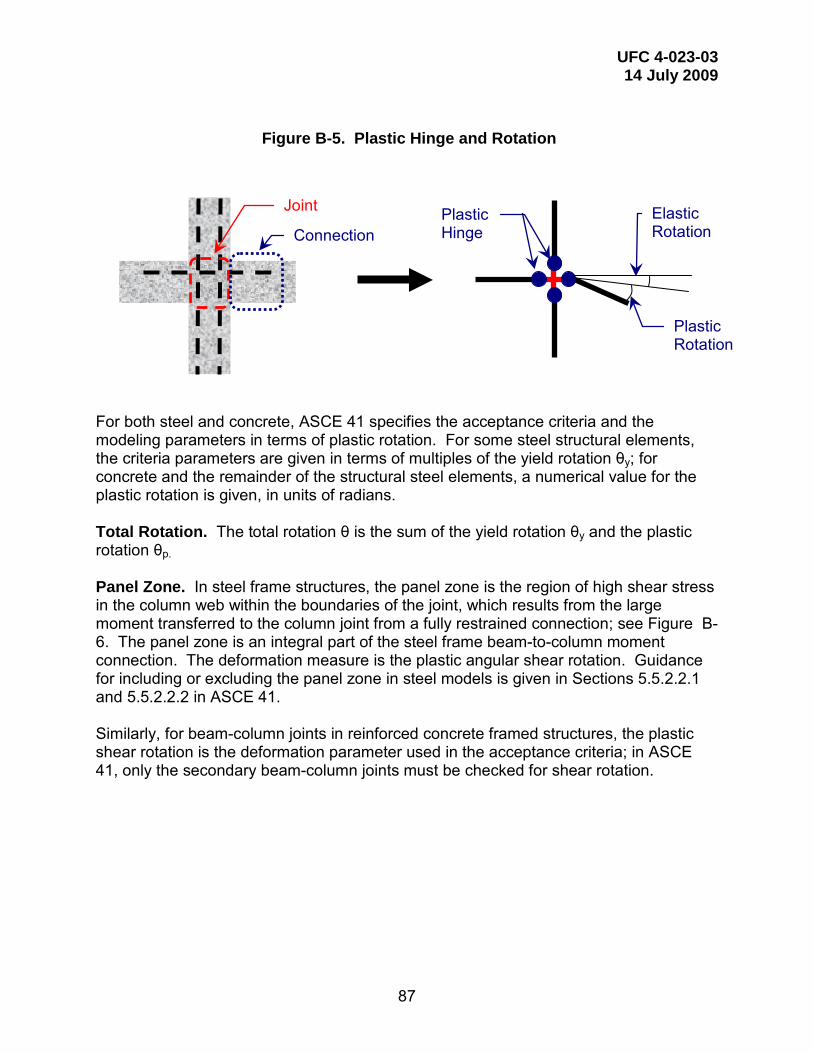
UFC 4-023-03 14 July 2009
87
Figure B-5. Plastic Hinge and Rotation
For both steel and concrete, ASCE 41 specifies the acceptance criteria and the modeling parameters in terms of plastic rotation. For some steel structural elements, the criteria parameters are given in terms of multiples of the yield rotation θy; for concrete and the remainder of the structural steel elements, a numerical value for the plastic rotation is given, in units of radians. Total Rotation. The total rotation θ is the sum of the yield rotation θy and the plastic rotation θp. Panel Zone. In steel frame structures, the panel zone is the region of high shear stress in the column web within the boundaries of the joint, which results from the large moment transferred to the column joint from a fully restrained connection; see Figure B-6. The panel zone is an integral part of the steel frame beam-to-column moment connection. The deformation measure is the plastic angular shear rotation. Guidance for including or excluding the panel zone in steel models is given in Sections 5.5.2.2.1 and 5.5.2.2.2 in ASCE 41. Similarly, for beam-column joints in reinforced concrete framed structures, the plastic shear rotation is the deformation parameter used in the acceptance criteria; in ASCE 41, only the secondary beam-column joints must be checked for shear rotation.
Joint
Connection Plastic Hinge
Plastic Rotation
Elastic Rotation

UFC 4-023-03 14 July 2009
88
Figure B-6. Panel Zone
Story Drift (Wall Structures). In ASCE 41, story drift is used as the nonlinear deformation measure for load-bearing wall structures (masonry, wood, and cold formed steel). The story drift is defined as the ratio of the lateral deflection at the top of a wall segment Δ to the overall height of the wall segment, as shown in Figure 7.
Figure B-7. Story Drift
While the story drift deformation criteria in ASCE 41 are applied to horizontal deformations due to lateral earthquake loads, this information can be used directly for
Panel Zone Column
Lateral Force
h
Δ

UFC 4-023-03 14 July 2009
89
progressive collapse analysis with vertical deformations due to removed wall sections, as shown in Figure 8.
Figure B-8. Vertical Wall Deflection (Drift)
Δ
Rotate
Similar to wall in Figure B-7
h

UFC 4-023-03 14 July 2009
90
APPENDIX C COMMENTARY
C-1 INTRODUCTION.
The goal of these design requirements is to provide a rational and uniform level of resistance to progressive or disproportionate collapse in new and existing structures. These requirements are threat-independent and are not intended to provide resistance to the local damage that may initiate the progressive collapse. Discussion and justification for the applicability requirements, design approaches, modeling techniques, and acceptance criteria are provided in this Appendix.
C-2 APPLICABILITY.
C-2.1 Three Story Requirement and Story Definition.
The required minimum height of 3 stories for progressive collapse design is taken from the original DoD guidance (DoD 2001). This requirement was based on a minimum threshold of 12 casualties in a progressive collapse event where it was assumed that the 2 bays on either side of a removed column or wall would collapse on each of 3 floors and that each bay/room would house 2 persons. Thus, the justification for setting the limit at 3 stories was determined by the level of casualties and not by the mechanics of progressive collapse as a function of structural characteristics.
As casualties are the key metric, a basement or penthouse structure is
defined to be a story if it is occupied. The definition of “occupied” in the International Building Code (IBC) is: “A room or enclosed space designed for human occupancy in which individuals congregate for amusement, educational or similar purposes or in which occupants are engaged at labor, and which is equipped with means of egress and light and ventilation facilities.” This definition was adopted in Section 1-2.1. Further, as noted in Section 1-2.1, any story that will not be occupied does not count towards the limit of 3 stories; this may include floors that house mechanical equipment or are used for storage.
Any portion of a building that is less than 3 stories is not required to meet the
progressive collapse design requirements of this UFC. However, any deleterious effect from the attachment of a short section of the building to the 3 story or higher section must be considered. In particular, peripheral tie forces must be placed in the 3+ story section of the building, at the boundaries between the short section and 3+ story section. For Alternate Path, the structural elements of the short section must be considered in the analysis and design of the 3+ story section if there is any possibility that the presence of the short section will affect the 3+ story section in a negative manner.
C-2.2 Clarification for Partial Occupancy.
UFC 4-010-01 DoD Minimum Antiterrorism Standards for Buildings requires that: “These standards only apply where DoD personnel occupy leased or assigned

UFC 4-023-03 14 July 2009
91
space constituting at least 25% of the net interior useable area or the area as defined in the lease, and they only apply to that portion of the building that is occupied by DoD personnel.” This 25% space threshold might be met by lease of entire stories in a multi-story building, e.g., DoD might lease the 3rd and 4th story in a 7 story building. As it is impractical to design or retrofit a building to resist collapse on only certain stories, this requirement from UFC 4-010-01 has been superseded by the requirement in Section 1-2-2.
C-3 OCCUPANCY CATEGORIES.
In the previous version of this UFC, the level of progressive collapse design was based on the level of protection (LOP), which, in turn, was based on the asset value of the building, as calculated with UFC 4-020-01 DoD Security Engineering Facilities Planning Manual. The asset value was a function of different asset categories, including General Population, Critical Infrastructure and Operations and Activities, Sensitive Information, and All Other Assets, including Mission Critical Personnel. Thus, there was a strong dependence upon the level of occupancy and the criticality to the user. In essence, this is a “consequence approach” in that probability of occurrence and the associated risk for progressive collapse cannot be explicitly considered due to the very small database of progressive collapse events. Thus, the level of casualties and the degradation of function are the key considerations.
In this UFC, different levels of design requirements are specified, depending
upon the Occupancy Category (OC). The OC is based on the occupancy categories defined in Table 1 Classification of Buildings and Other Structures for Importance Factors, in \1\ UFC 3-301-01, Structural Engineering /1/ . The descriptions for “Nature of Occupancy” in \1\ Table 2-2 of UFC 3-301-01 /1/ are very similar to those in ASCE 7 Minimum Design Loads for Buildings and Other Structures, however, some modifications specific to DoD have been made.
It is noted that the OC is independent of threat or initiating event, and, as with
the previous LOP approach, this is consequence-based where occupancy level and function are key parameters in defining the level of progressive collapse design.
C-4 DESIGN REQUIREMENTS.
The design requirements for OC I through OC IV are listed in Table 2-2 and briefly summarized in the following sections.
C-4.1 OC I Design Requirement.
These buildings present little risk to human life and no progressive collapse design is required providing the buildings were designed to the extant building code.
C-4.2 OC II Design Requirement.
For OC II structures, one of two options must be chosen: Option 1, Internal, peripheral and vertical Tie Forces with Enhanced Local Resistance for the corner and

UFC 4-023-03 14 July 2009
92
penultimate columns or walls at the first story OR Option 2, Alternate Path applied to specific locations. For load-bearing wall structures, the AP method may be the best choice, as the designer can take advantage of the building’s inherent redundancy as well as the ability to develop deep beam or arching action.
In the 2005 UFC 4-023-03, only tie forces were used for LLOP (i.e., OC II)
buildings. Tie Forces can be very difficult to implement in existing buildings and even for some new types of load-bearing wall construction. Since many load-bearing wall buildings are very redundant and may meet the Alternate Path requirements while staying elastic, Option 2 (as suggested in the Eurocode) was added. Thus, this provides some relief for existing buildings. For many load-bearing buildings, the walls are identical and a single set of calculations for a typical wall may be sufficient.
C-4.2.1 OC II Option 1, Tie Forces and Enhanced Local Resistance.
The goal of the Tie Force requirement is to enhance the structural integrity evenly throughout the structure, by prescriptively defining the magnitude, location, and distribution of the Tie Forces and without requiring significant design or analysis effort. While the Tie Forces are distributed uniformly throughout the structure, the response and performance of the structure varies with the location at which the initial damage occurs. As discussed in Stevens 2008, the removal of a corner column or wall or a penultimate corner or wall can lead to local collapse of a portion of the bay since the lateral support to anchor the Tie Forces has been removed or reduced. This damage will extend to the height of the building, but is unlikely to progress horizontally. While this damage is spatially limited and does not threaten the rest of the building, it is a limitation of the Tie Force approach. Therefore, to reduce the possibility that the corner or penultimate column or wall will be damaged, the Enhanced Local Resistance approach is applied to these elements at the first story above grade, as discussed in Section 3-3.
C-4.2.2 OC II Option 2, Alternate Path.
While the Tie Force requirement can be easily implemented in new construction for some material types, it can be difficult to apply to existing buildings and to non-ductile floor systems. The option to use the Alternate Path method provides another approach by which to evaluate an existing structure. It also allows the designer to account for the inherent and often substantial collapse resistance due to the natural redundancy and available load paths, commonly found in load-bearing wall structures. Many of the structures in OC II will be short (5 stories or less) load-bearing wall buildings with a uniform or regular layout. Hand calculations can be used to demonstrate bridging by deep beam action or arching over removed wall sections for a typical wall and those results applied to the similar walls in the structure.
C-4.3 OC III Design Requirement.
For OC III, two requirements must be satisfied: Alternate Path and Enhanced Local Resistance. The consequence of collapse is greater for this Occupancy Category, which also increases the (unknown and unquantifiable) probability of a

UFC 4-023-03 14 July 2009
93
deliberate attack. Thus, a specified level of resistance to loss of a column or wall is provided by the Alternate Path method. Additional protection is provided by minimizing the likelihood of a non-ductile failure of the columns and walls at the building perimeter, in the first story above grade, through the Enhanced Local Resistance requirement.
For OC III (and IV), the buildings will tend to be large, framed structures, and the specified locations for column or wall removal are only the minimal locations that must be considered; the engineer must also consider locations where the geometry of the structure changes significantly. Since the regular portion of the structure should be covered by the minimum cases and all unusual portions of the structure should be identified by the engineer, this requirement applied to all columns or load-bearing walls in the structure. However, note that for OC III (and OC IV) structures without underground parking or other areas of uncontrolled public access, internal column removal does not need to be considered.
C-4.4 OC IV Design Requirement. For OC IV, three requirements must be satisfied: Alternate Path, Tie Forces,
and Enhanced Local Resistance. The addition of the Tie Force requirement to those of OC III provides another layer of resistance to collapse and will supplement the flexural resistance developed through the AP method. In addition, the ELR requirement is applied to all perimeter walls and columns, over the two stories above grade and the level of flexural resistance is increased, to minimize the possibility that two columns or walls will be removed in the same event.
C-5 TIE FORCES.
C-5.1 General.
The Tie Force requirement is designed to enhance the structural integrity of the building by prescriptively defining tensile force capacities of the members and connections, in terms of strength, location, and distribution. This prescriptive method is simple in that detailed or complicated models and analyses are not required, yet it must also be based on mechanical principles, such as equilibrium and deformation compatibility, as applied to a damaged structure.
C-5.2 Previous Requirements.
The Tie Force requirements in the 2005 UFC 4-023-03 were based on the British Building Standards (before the Eurocodes were introduced) for reinforced concrete, structural steel, and masonry. The previous Tie Force requirements were material-specific, with limited similarity across the different materials in terms of location, distribution, magnitude, and other details. As discussed in the 2005 UFC 4-023-03, the Tie Forces for Reinforced Concrete could be related to an assumed catenary behavior of the floor system, but similar justification could not be found for the other materials.
One common and justified criticism of the previous Tie Force approach was that the great majority of steel connections as well as some RC connections are not
UFC 4-023-03 14 July 2009
94
capable of providing the magnitudes of rotation that are needed to develop the typically small Tie Forces that were specified. Thus, the connections would fail before the beams, girders, and spandrels could develop axial force. This is also true for Tie Forces distributed in floor systems with limited ductility, such as plywood on engineered I-joists or precast planks with limited continuity across connections.
C-5.3 New Tie Force Approach.
Due to the inability of many connections to sustain large rotations, a new approach was proposed and employed in this UFC. In this new approach, the floor system now provides and carries the internal Tie Forces, thus removing these Tie Forces from the beams, girders, and spandrels. In essence, the floor system will transfer the vertical loads from the damaged section, via catenary or membrane action, to the undamaged horizontal members, which, in turn, will transfer the load into the vertical load carrying elements, as shown in Figure C-1.
While the internal and peripheral ties are now placed in the floor system, a
designer is allowed to use the members and connections for steel, reinforced concrete and other materials, if it can be shown that the connections can carry the tensile forces due to a removed column/wall without failure due to large deformations and rotations.
Additional modifications from the previous UFC include:
• Requirements are now material-independent. • Explicit tying to external and corner walls and columns is removed. • Provisions to address openings in the floor system (stairwells,
elevators, atria) are included. • Provisions are added to account for large variations in floor loads over
the plan geometry of a single floor.

UFC 4-023-03 14 July 2009
95
Figure C-1. Damaged and Undamaged Structural Elements
C-5.4 Justification for the Tie Force Approach.
In the development of this UFC, analytical and numerical methods were used to derive reasonable tie force requirements that can be used for different column and wall loss locations for braced frames, moment frames, and load-bearing wall structures, with floor systems that are capable of developing membrane or catenary response; the details can be found in Stevens 2008. These floor systems include reinforced concrete (RC) floors with integral slabs, composite construction with steel decks and RC, and floor systems that incorporate a grid of rebar or welded wire fabric.
To develop the internal and peripheral tie force requirements for framed structures, 6 different column scenario removals were assessed, using simple catenary theory, membrane theory, and finite element analysis; see Stevens 2008. The removal locations included the corner column, penultimate column, internal column, near penultimate column, edge column, and near edge column, as shown in Figure C-2. In addition to assessing the tie force magnitudes required to carry the loads in catenary or membrane action, the transfer of the vertical force from the damaged panel to the undamaged structures was assessed. Finite element analyses were also performed to determine the dynamic effects created by the sudden loss of column support; the results of these analyses were used to modify the Tie Force equations. Load-bearing wall structures were also considered, but not as extensively as for framed structures. As the floor system is the critical element for developing and supplying the internal and
Gravity Beams
Framing Members
Panel Region
Damaged and Ineffective Member
Undamaged and Effective Member
Removed Column Transfer of Vertical Load Through Floor
Damaged and Ineffective Member
Undamaged and Effective Member

UFC 4-023-03 14 July 2009
96
peripheral tie forces, many of the findings from the framed structure assessment are directly applicable to load-bearing wall structures.
The application of peripheral ties around the perimeter of openings was also investigated with numerical methods and the loads were shown to be adequately transferred from the damaged area to the peripheral ties and to the undamaged elements. Care must be taken to develop, lap or anchor the peripheral ties at openings in the floor system (stairways, elevators, atria, etc), such that the strength can be developed. This same approach was used to develop the sub-areas and peripheral ties at the boundary between sub-areas with different floor loads.
Figure C-2. Column Removal Locations
C-5.5 Tie Forces in Roof Systems The roof system must meet the Tie Force requirements in Section 3-1. As
with floor systems, these requirements will be more easily met with some types of floor systems, such as reinforced concrete slabs and composite decks.
For lightweight systems such as steel deck and joist roof systems, sufficient
strength and ductility should be available in the direction of the joist, providing that the bottom chord of the joist does not connect to the column or beam; see Figure C-3. If so, then the top chord of the joist can be used to supply the Tie Force, providing that the load path is continuous across each vertical support. Two approaches can be used in the transverse direction. In the first, steel shapes (rods, angles, bars, etc) could be placed through the open webs. Attachments of these internal ties to the peripheral ties must be capable of developing the longitudinal and transverse tie forces. Second, a steel deck that spans in the transverse direction to the joist could be used to supply the internal Tie Force provided that the welds or other connections between the steel deck
Internal
Penultimate Edge
Near Edge Near Penultimate
Corner

UFC 4-023-03 14 July 2009
97
sections are sufficient to develop the Tie Force. While there may be crushing of the steel deck where it crosses the joist or other vertical support, the upper surface of the deck should remain intact and capable of supplying tension up to 0.20-rad; see Figure C-4.
Figure C-3. Tie Force in Upper Chord of Roof Joist
Figure C-4. Tie Force in Steel Deck
C-5.6 Location Restrictions on Internal and Peripheral Ties. As mentioned, one goal of the revised Tie Force approach is to remove the
Tie Forces from the flexural members, which typically are not capable of sustaining the large amount of deformation associated with catenary and diaphragm action. For example, if a peripheral tie was placed in a deep edge beam with limited ductility, the peripheral tie may be damaged or failed by the resulting motion of the edge beam after a column is removed. Within the floor plan, the internal ties can be shifted to either side of the beam, girder or spandrel for framed structures; for flat plate or flat slab structures without edge beams or internal beams, the tie forces can be placed on the column lines and pass through the columns. However, the peripheral ties also need to be close to the edge of the structure and therefore the peripheral ties are permitted to be close to
Weld sufficient to develop tie force strength
Top surface
Bottom surface
Joist
A
A
Crushing may occur at bottom surface, but top surface should be intact, after 0.20-rad.
A-A
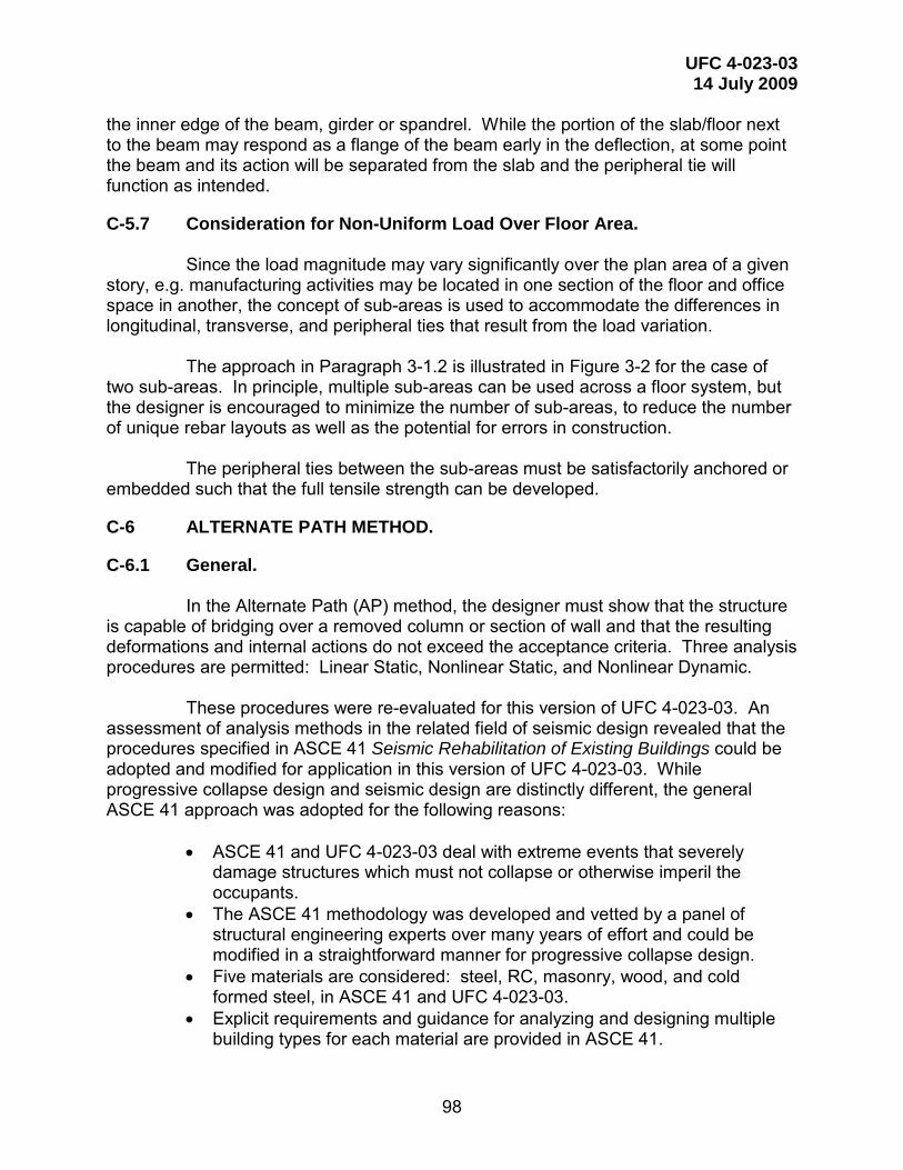
UFC 4-023-03 14 July 2009
98
the inner edge of the beam, girder or spandrel. While the portion of the slab/floor next to the beam may respond as a flange of the beam early in the deflection, at some point the beam and its action will be separated from the slab and the peripheral tie will function as intended.
C-5.7 Consideration for Non-Uniform Load Over Floor Area.
Since the load magnitude may vary significantly over the plan area of a given story, e.g. manufacturing activities may be located in one section of the floor and office space in another, the concept of sub-areas is used to accommodate the differences in longitudinal, transverse, and peripheral ties that result from the load variation.
The approach in Paragraph 3-1.2 is illustrated in Figure 3-2 for the case of
two sub-areas. In principle, multiple sub-areas can be used across a floor system, but the designer is encouraged to minimize the number of sub-areas, to reduce the number of unique rebar layouts as well as the potential for errors in construction.
The peripheral ties between the sub-areas must be satisfactorily anchored or
embedded such that the full tensile strength can be developed.
C-6 ALTERNATE PATH METHOD.
C-6.1 General. In the Alternate Path (AP) method, the designer must show that the structure
is capable of bridging over a removed column or section of wall and that the resulting deformations and internal actions do not exceed the acceptance criteria. Three analysis procedures are permitted: Linear Static, Nonlinear Static, and Nonlinear Dynamic.
These procedures were re-evaluated for this version of UFC 4-023-03. An
assessment of analysis methods in the related field of seismic design revealed that the procedures specified in ASCE 41 Seismic Rehabilitation of Existing Buildings could be adopted and modified for application in this version of UFC 4-023-03. While progressive collapse design and seismic design are distinctly different, the general ASCE 41 approach was adopted for the following reasons:
• ASCE 41 and UFC 4-023-03 deal with extreme events that severely
damage structures which must not collapse or otherwise imperil the occupants.
• The ASCE 41 methodology was developed and vetted by a panel of structural engineering experts over many years of effort and could be modified in a straightforward manner for progressive collapse design.
• Five materials are considered: steel, RC, masonry, wood, and cold formed steel, in ASCE 41 and UFC 4-023-03.
• Explicit requirements and guidance for analyzing and designing multiple building types for each material are provided in ASCE 41.

UFC 4-023-03 14 July 2009
99
• Careful attention is given in ASCE 41 to deformation- and force-controlled actions, as well as primary and secondary components.
• The acceptance criteria and modeling parameters in ASCE 41 can be scaled for different structural performance levels.
The most significant differences between the physics, intent, and approaches
underlying UFC 4-023-03 and ASCE 41 are: • Extent. The seismic event involves the entire structure, whereas, for
progressive collapse, the initial event is localized to the column/wall removal area.
• Load Types. Seismic loads are horizontal and temporary; for progressive collapse, the loads are vertical and permanent.
• Damage Distribution. For earthquake design, it is accepted that the damage will be distributed throughout the structure. For progressive collapse, the initial damage is localized and the goal is to keep the damage from progressing.
• Connection and Member Response. In typical tests to evaluate the seismic performance of connections and members, cyclic loads with increasing magnitude are applied, without axial loading, and the resulting curves are used to develop “backbone” curves. In progressive collapse, the connection and member experiences one half cycle of loading, often in conjunction with a significant axial load, due to large deformations and catenary response.
These differences have been accommodated in the adaptation of ASCE 41
procedures and criteria to Alternate Path modeling and design for progressive collapse. The significant elements of the Alternate Path method are presented in the following paragraphs.
C-6.2 Peer Review. In the previous UFC, a peer review was required for Alternate Path design of
medium and high level of protection buildings. In this UFC, a peer review is no longer required as this is a policy issue that is best addressed by the building owner. However, peer reviews are strongly recommended, for Alternate Path design in any Occupancy Category.
C-6.3 Alternative Rational Analysis.
Any rational alternative analysis procedure that is based on fundamental principles of engineering mechanics and dynamics may be used. For load-bearing wall structures with uniform and regular wall layouts or simple frame structures, hand calculations or spreadsheet applications may be appropriate and more efficient. New software design and analysis tools, based on novel analytical formulations, may be used as well. However, any alternative rational analyses must incorporate or satisfy the following:

UFC 4-023-03 14 July 2009
100
• the acceptance criteria contained in Section 3-2.10 and in Chapters 4
through 8. • the specified locations and sizes of removed columns and load-bearing
walls in Section 3-2.9. • the ASCE 7 extreme event load combination. • the load increase factors and dynamic increase factors in Sections 3-
2.11.5 and 3-2.12.5 for linear static and nonlinear static analyses, respectively.
• the requirements of Section 3-2.11.1 must be met for a Linear Static analysis.
All projects using alternative rational analysis procedures shall be reviewed
and approved by an independent third-party engineer or by an authorized representative of the facility owner.
C-6.4 Load and Resistance Factor Design.
Load and Resistance Factor Design (LRFD) continues to be used in this version of UFC 4-023-03 as well as the ASCE 7 extraordinary event load combination is employed. Also, unlike ASCE 41, strength reduction factors are employed in determining the design strength. The strength reduction factors account for deficient material strength, construction errors, design flaws and other uncertainties that can act to reduce the strength of the building; all of these uncertainties are “locked” into the building when it is constructed and will still be there when a progressive collapse event occurs. Therefore, the strength reduction factors, load factors, and the LRFD approach continue to be employed in this version of UFC 4-023-03.
C-6.5 Primary and Secondary Components.
The designation of elements, components and connections as primary or secondary is left to the judgment of the engineer; however, in all cases, the engineer must verify that the structure and its elements, components and connections are capable of meeting the structural acceptance criteria in Paragraph 3-2.10.
For evaluation of existing buildings, the engineer may wish to include
elements that are typically considered secondary, i.e., gravity beams, slabs, infill walls, etc. If such elements are included as part of the system that resists the vertical loads and collapse, they become primary components by definition and must meet the primary component acceptance criteria.
C-6.5.1 Secondary Components. While secondary components are designated by the engineer as not
contributing to the resistance of gravity loads and progressive collapse, they are a critical part of the load path for the vertical loads and they pose a risk to the building occupants if they drop into the space below, potentially creating additional damage and

UFC 4-023-03 14 July 2009
101
collapse. As an example, the gravity beams in a bay supporting heavy mechanical equipment could be treated as secondary components; however, the shear tab connections with a deep bolt group could have reduced allowable rotations/m-factors such that the rotations from the column removal could be sufficient to fail the shear tab connections. Secondary components are not included as part of the models in the linear or nonlinear procedures but must be checked against the acceptance criteria given in this UFC and in ASCE 41.
C-6.5.2 Secondary Component Acceptance Criteria.
C-6.5.2.1 Linear Procedures. For linear procedures, the secondary component must meet the force- and
deformation-controlled criteria of Section 3-2.11.7. Since the secondary component was not included in the math model, the engineer may either re-run the math model with the secondary components incorporated or use the calculated displacements to assess the component’s deformation and force actions. An example of the latter option is shown in the steel design example in Appendix E.
Before the column or wall is removed, the structure will be initially stressed
and deformed due to the gravity load combination given in Equation 3-9. When the column or wall is removed, additional stresses and deformations are added. For the purposes of evaluating the deformation-controlled actions, it is conservatively assumed that the deformations and stresses under gravity load and prior to column or wall removal are at the yield limit, i.e., that each component in the structure is on the verge of becoming nonlinear. The effect of this is to reduce the allowable m-factor by 1.0 when evaluating the deformation-controlled actions for each component. This approach is used in the steel example in Appendix E. For force-controlled actions, the forces under the initial gravity loads must be determined, perhaps by examining original design calculations if they exist or by performing simplified load and/or structural analysis of the member. This force is added to the forces induced by the column or wall removal, which are calculated with the deformations from the linear static model.
C-6.5.2.2 Nonlinear Procedures. For nonlinear procedures, the secondary component must meet the force-
and deformation-controlled criteria of Sections 3-2.11.7 and 3-2.13.6. Since the secondary component was not included in the math model, the engineer may either re-run the math model with the secondary components incorporated or use the calculated displacements to assess the component’s deformation and force actions.
Before the column or wall is removed, the structure will be initially stressed
and deformed due to the gravity load combination given in Equation 3-9. When the column or wall is removed, additional stresses and deformations are added. For the deformation-controlled actions, it is conservatively assumed that the deformations and stresses under gravity load and prior to column or wall removal are at the yield limit, i.e, that each component in the structure is on the verge of becoming nonlinear. Thus, the rotations and deformations due to column removal can be directly compared to the

UFC 4-023-03 14 July 2009
102
nonlinear acceptance criteria (allowable plastic rotation, etc) in this UFC and ASCE 41. For force-controlled actions, the forces under the initial gravity loads must be determined, perhaps by examining original design calculations if they exist or by performing simplified load and/or structural analysis of the member. This force is added to the forces induced by the column or wall removal, which are calculated with the deformations from the nonlinear model.
C-6.6 Analysis Procedures.
C-6.6.1 Linear Static.
The Linear Static approach in the 2005 UFC 4-023-03 had been replaced with an “m-factor” procedure, very similar to that defined in ASCE 41. The two significant departures from the ASCE 41 procedure are in the definition of the “Irregularity Limitations” in Paragraph 3-2.11.1.2 and the use of a load increase factor appropriate for progressive collapse loading. The irregularity limitations have been adjusted due to the inherent difference between lateral/seismic loading and vertical/progressive collapse loading and the related criticality of different building geometric and strength features. As discussed in Section C-6.8, a new load increase factor to account for nonlinearity and dynamic effects has been implemented.
C-6.6.2 Nonlinear Static. The Nonlinear Static procedure is similar to that specified in the 2005 UFC 4-
023-03 and in ASCE 41. Two exceptions are the modeling parameters and the acceptance criteria, which are now taken from ASCE 41, unless specifically modified in Chapters 4 to 8 of this UFC. One advantage of ASCE 41 is that guidance is provided for the development of analytical and numerical models for a number of distinct structural systems, including the determination of connection and member properties
One significant difference from ASCE 41 and the 2005 UFC 4-023-03 is the
specification of a dynamic increase factor that is applied to the loads on the bays above the removed column or wall location to account for dynamic effects. In the 2005 UFC 4-023-03 and in the 2003 GSA Progressive Collapse Analysis and Design Guidelines for New Federal Office Buildings and Major Modernization Projects (“GSA Guidelines”), the load factor was set at 2, as for the Linear Static analysis, despite the explicit incorporation of nonlinear effects in the Nonlinear Static procedure. The dynamic increase factor is discussed in Section C-6.4.
C-6.6.3 Nonlinear Dynamic.
The Nonlinear Dynamic procedure is essentially unchanged from the 2005 UFC 4-023-03, with the exception of the incorporation of the modeling parameters and acceptance criteria from ASCE 41.

UFC 4-023-03 14 July 2009
103
C-6.7 Loads. As with the 2005 UFC 4-023-03, the ASCE 7 extraordinary event load
combination is employed, with the exception that the 0.2W wind load has been replaced with the lateral load given in Equation 3-11: LLAT = 0.002ΣP. As with the wind load, the lateral load must be applied to all four sides of the building, one at a time.
The original 0.2W load was included to provide a nominal lateral load, to
check stability of the damaged structure. It was not based on the actual probability of a wind load of a certain magnitude. ASCE 7 will now adopt the lateral load in Equation 3-11, which was first proposed in the 1998 Structural Stability Research Council publication Guide to Stability Criteria for Metal Structures 1998 and is employed in the AISC Manual of Steel Construction, LRFD. The lateral load of 0.002ΣP is based on an analysis of the out-of-plumbness imperfection inherent in real structures. As the building response may be asymmetric, and the actions due to the lateral loads may or may not be additive to the critical action, the lateral load is applied orthogonal to each exterior face, one at a time, i.e., for a rectangular building, four Alternate Path analyses will still be required for each column/wall removal scenario, as is currently done for wind loads.
C-6.8 Load and Dynamic Increase Factors.
Three analytical procedures may be employed: Linear Static, Nonlinear Static, and Nonlinear Dynamic. As progressive collapse is a dynamic and nonlinear event, the applied load cases for the static procedures require the use of load increase factors or dynamic increase factors, which approximately account for inertial and nonlinear effects. For both Linear Static and Nonlinear Static, the 2005 UFC 4-023-03 and the GSA Guidelines use a load multiplier of 2.0, applied directly to the progressive collapse load combination.
Three issues with the use of a fixed factor of 2 have been identified. First,
the same load multiplier is used for Linear Static and Nonlinear Static analyses, although the Nonlinear Static analysis incorporates nonlinearity. Second, an increase factor of 2.0 is not appropriate for the majority of LS and NS cases. The maximum dynamic displacement of an instantaneously applied and sustained load in a linear analysis is twice the displacement achieved when the load is applied statically. If a structure is designed to remain elastic, a factor of 2.0 would be appropriate. However, in extreme loading events, it is typical to design structures to respond in the nonlinear range. Thus, the dynamic increase factor (DIF) that allows a Nonlinear Static solution to approximate a Nonlinear Dynamic solution, is typically less than 2. On the other hand, the load increase factor (LIF) for a Linear Static analysis must be greater than 2, since dynamic and nonlinear effects are present. Third, the load enhancement factor did not vary with the structural performance level, i.e., a structure is assigned a load enhancement factor of 2.0 regardless of whether the designer wants to allow significant structural damage or very little damage.

UFC 4-023-03 14 July 2009
104
A study was undertaken to investigate the factors needed to better match the results of the LS and NS static procedures to the ND results; see McKay et al. 2008. As in ASCE 41, structural deformation was considered to be the best metric for approximating structural damage. To match the ND deformation levels, SAP2000 models of reinforced concrete and steel multi-story models were developed and analyzed with LS, NS, and ND procedures. For the LS and ND models, the loads were varied until agreement with the NS model was reached. The ASCE 7 extreme event load case was used for all analyses.
The range of nonlinear structural deformations used in this study was based primarily on the acceptance criteria in ASCE 41, with some modifications for reinforced concrete, for which the Life Safety values were increased by a factor of 3.5. For reinforced concrete, the allowable deformation criteria in ASCE 41 are much smaller than indicated by test data from blast- and impact-loaded RC structural members. In addition, the conservative ASCE 41 RC criteria are based on backbone curves derived from cyclic testing of members and joints, whereas only one half cycle is applied in a progressive collapse event.
As an example, the results of this procedure for the Dynamic Increase Factor (DIF), used for Nonlinear Static analyses of steel structures, are shown in Figure C-5, where the DIF is shown as a function of the normalized rotation (allowable plastic rotation divided by the rotation at yield of the cross section). The data points in this plot were obtained by analyzing a range of buildings with various heights, bay dimensions and structural details. With this plot the DIF can be chosen as a function of the level of nonlinear behavior (i.e., structural performance level) that the designer wishes to employ or, else, the level of nonlinear behavior can be assigned, resulting in a specific DIF. In this UFC, the designer must find the smallest normalized rotation for any structural component or connection within the region of the structure affected by the column removal and will use this value to determine the DIF from the recommended equation in Figure C-5.
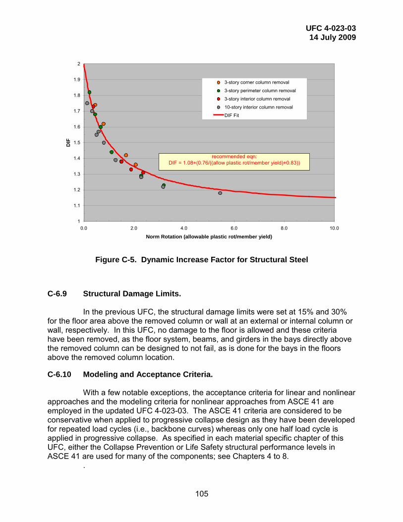
UFC 4-023-03 14 July 2009
105
Figure C-5. Dynamic Increase Factor for Structural Steel
C-6.9 Structural Damage Limits. In the previous UFC, the structural damage limits were set at 15% and 30%
for the floor area above the removed column or wall at an external or internal column or wall, respectively. In this UFC, no damage to the floor is allowed and these criteria have been removed, as the floor system, beams, and girders in the bays directly above the removed column can be designed to not fail, as is done for the bays in the floors above the removed column location.
C-6.10 Modeling and Acceptance Criteria.
With a few notable exceptions, the acceptance criteria for linear and nonlinear approaches and the modeling criteria for nonlinear approaches from ASCE 41 are employed in the updated UFC 4-023-03. The ASCE 41 criteria are considered to be conservative when applied to progressive collapse design as they have been developed for repeated load cycles (i.e., backbone curves) whereas only one half load cycle is applied in progressive collapse. As specified in each material specific chapter of this UFC, either the Collapse Prevention or Life Safety structural performance levels in ASCE 41 are used for many of the components; see Chapters 4 to 8.
.
1
1.1
1.2
1.3
1.4
1.5
1.6
1.7
1.8
1.9
2
0.0 2.0 4.0 6.0 8.0 10.0
Norm Rotation (allowable plastic rot/member yield)
DIF
3-story corner column removal
3-story perimeter column removal
3-story interior column removal
10-story interior column removal
DIF Fit
recommended eqn:DIF = 1.08+(0.76/((allow plastic rot/member yield)+0.83))

UFC 4-023-03 14 July 2009
106
The notable exceptions/modifications to the acceptance and modeling criteria include RC beams and slabs and a number of steel connections. These changes are motivated and justified by experimental data and numerical analysis results, as discussed later in this Appendix.
C-7 ENHANCED LOCAL RESISTANCE.
The second direct design approach is Specific Local Resistance (SLR) or structural hardening, in which key or critical elements of the structure are designed for a specific load, such as blast or vehicle impact. This approach reduces the likelihood or extent of the initial damage and can be effective, for those cases where the threat can be quantified through risk analysis or specified through prescriptive design requirements. SLR can be a cost-effective method for providing resistance to collapse prevention, particularly for existing structures. The main shortcoming to this method is the requirement to define the threat or design load, as this information could be used to plan a deliberate attack on the structure; because of this, the threat information may be considered classified, restricting its use by the general public. Also, philosophically, progressive collapse design is typically considered to be threat-independent and if a specific threat such as an explosive device is specified, separate design guidance for hardening buildings is available.
In the 2005 UFC 4-023-03, a version of SLR was implemented in the
Additional Ductility Requirement (ADR), which specified that the shear capacity of a ground story column or wall exceed the flexural capacity. With this requirement, the columns or walls will fail in flexure, which provides a more ductile and controlled response than the sudden failure associated with shear. This requirement can be implemented cost-effectively in new construction and provides a significant benefit.
A modified or enhanced version of SLR is implemented in this UFC to provide
a nominal level of protection for perimeter columns and walls. This procedure is also threat independent and is referred to as Enhanced Local Resistance (ELR) to differentiate it from SLR and ADR. The development and design approach of this method is “tuned” to the inherent structural robustness of the system as discussed in Marchand and Stevens 2008. A charge weight that will destroy multiple columns or wall sections, depending upon standoff and location, was determined for a variety of representative structures. An analysis of the data resulted in required enhancement factors of 2 and 1.5 for the flexural resistance of columns and walls, respectively. The shear capacity of the column or wall and the connections to the lateral force resisting elements is also stipulated to be greater than the flexural capacity, to provide a ductile and more controlled failure mode.
For OC II Option 1, the baseline flexural resistance of the columns and walls
is determined based on the existing or as-designed structure. For OC III, the baseline flexural resistance is based on the structure design after the AP method has been applied.
A higher level of resistance is required for OC IV structures; in this case, two
flexural resistances are compared and used to determine the enhanced flexural

UFC 4-023-03 14 July 2009
107
resistance. Because an OC IV building in a seismic region will have significantly larger columns than the same OC IV building in a non-seismic region, the seismic structure will also have significantly higher inherent flexural resistance. However, both buildings should provide the same protection to the occupants. To accomplish this and to provide a reasonable baseline flexural resistance, the design of the building based on only gravity loads is used to define the baseline flexural resistance. If a gravity loads only design was not accomplished during the design effort, it must be performed. It is anticipated that mathematical models will be created for OC IV buildings and the effort to use them for a gravity loads only design should not be significant. After the baseline flexural resistance is determined with the column design from the gravity loads-only structural design, it is multiplied by 2.0 and compared to the existing flexural resistance. The existing flexural resistance is based on the column design after the Alternate Path method is applied to the final structure (i.e., the structural design based on wind, seismic, snow, and gravity loads). The larger of 2.0 times the baseline flexural resistance and the existing flexural resistance is defined as the enhanced flexural resistance. If the enhanced flexural resistance is greater than the existing flexural resistance, then the design of the column must be upgraded to provide this resistance. The same procedure applies for load-bearing walls but in this case, the baseline flexural resistance is multiplied by 1.5.
Finally, for all 3 cases of ELR (OC II Option 1, OC III, and OC IV), the shear
resistance of the columns and load-bearing walls and their connections must meet or exceed the enhanced flexural resistance.
C-8 REINFORCED CONCRETE.
C-8.1 Reinforced Concrete Beams and Joints.
For new and existing construction, the design strength and rotational capacities of the beams and beam-to-column-to-beam joints shall be determined with the guidance found in ASCE 41, as modified with the acceptance criteria provided in Paragraph 4-4.3.
C-8.2 Structural Performance Levels.
To determine the appropriate structural performance level and the corresponding modeling and acceptance criteria from ASCE 41, the types of loading and resulting performance of reinforced concrete beams and beam-column joints were assessed. In seismic events, the structural elements and connections are subjected to primarily shear and bending with little axial tension. Under progressive collapse conditions, axial tension is developed in the beam, as they undergo large displacements in a double-span condition and the beam starts to behave as a catenary.
Conceptually, the damage states reflected in the Life Safety category make sense for progressive collapse. In seismic design, it is assumed that the primary components can sustain significant degradation to their lateral load resisting behavior as long as they can still support the gravity loads; for progressive collapse, the primary components must resist gravity loads during and after the event. As defined in ASCE
UFC 4-023-03 14 July 2009
108
41, Collapse Prevention results in a damage state for which there is little additional deformation capacity and the stability of the system has been severely compromised. Life Safety provides a greater reserve in terms of nonlinear deformation and strength and thus is used for the majority of the steel acceptance criteria.
C-8.3 Modeling and Acceptance Criteria for Reinforced Concrete.
The majority of the modeling parameters, acceptance criteria and linear m-factors for reinforced concrete are chosen as the Life Safety values in Chapter 6 of ASCE 41 for primary and secondary components. Modifications to the modeling and acceptance criteria for beams and slabs were made based on data from blast- and impact-loaded beams and other flexural members. For RC beams and slabs controlled by flexure, the modeling and acceptance criteria values for Collapse Prevention were multiplied by a factor of 2.5 for primary members and 2.0 for secondary members. For all other conditions and cases of beams and slabs, the Life Safety values are used.
C-8.4 Best Practice Recommendation. To insure ductile and energy absorbing response in new construction of
reinforced concrete structures, it is recommended that the primary reinforced concrete beams and beam-to-column-to-beam joints comply with the provisions for special moment frames in ACI 318. These code provisions include ductile detailing requirements for longitudinal reinforcement, transverse reinforcement, required shear strength, and development length of bars in tension.
C-9 STRUCTURAL STEEL.
C-9.1 Structural Steel Connections.
A variety of steel frame connection types are listed in Table C-1 and illustrated in Figures C-6 through C-8. This list constitutes an inventory of connection types that have been used either in the past and/or present for standard building code design applications (gravity, wind and earthquake loads).

UFC 4-023-03 14 July 2009
109
Table C-1. Steel Frame Beam-to-Column Connection Types
Connection Description Type Figure
Welded Unreinforced Flange (WUF)
Full-penetration welds between beams and columns, flanges, bolted or welded web, designed prior to code
changes following the Northridge earthquake. FR C-6(a)
Welded Flange Plates (WFP)
Flange plate with full-penetration weld at column and fillet welded to beam flange FR C-6(b)
Welded Cover-Plated Flanges Beam flange and cover-plate are welded to column flange FR C-6(c)
Bolted Flange Plates (BFP)
Flange plate with full-penetration weld at column and field bolted to beam flange FR or PR C-6(d)
Improved WUF-Bolted Web(1)
Full-penetration welds between beam and column flanges, bolted web, developed after Northridge Earthquake FR C-6(a)
Improved WUF-Welded Web
Full-penetration welds between beam and column flanges, welded web developed after Northridge Earthquake FR C-6(a)
Free Flange
Web is coped at ends of beam to separate flanges, welded web tab resists shear and bending moment due to
eccentricity due to coped web developed after Northridge Earthquake
FR C-6(e)
Welded Top and Bottom Haunches
Haunched connection at top and bottom flanges developed after Northridge Earthquake FR C-6(f)
Reduced Beam Section (RBS) (2)
Connection in which net area of beam flange is reduced to force plastic hinging away from column face developed
after Northridge Earthquake FR C 6(g)
Top and Bottom Clip Angles
Clip angle bolted or riveted to beam flange and column flange PR C-7(a)
Bolted Double Split Tee(2)
Split tees bolted or riveted to beam flange and column flange PR C-7(b)
Composite Top and Clip Angle Bottom
Clip angle bolted or riveted to column flange and beam bottom flange with composite slab PR C-7(a)
similar
Bolted Flange Plates Flange plate with full-penetration weld at column and bolted to beam flange PR C-6(d)
Bolted End Plate Stiffened or unstiffened end plate welded to beam and bolted to column flange PR C-6(c)
Shear Tab Connection with or without(2) floor
deck
Simple gravity connection with shear tab, may have composite floor deck PR C-6(d)
Kaiser Bolted Bracket®, SMF moment connection with fastened cast steel haunch brackets that are bolted to the column flange and either
fillet-welded or bolted to both beam flanges. FR C-9
SidePlate® SMF moment connection with full-depth side plates and
fillet welds, developed following the 1994 Northridge earthquake.
FR C-10
SlottedWeb™ SMF moment connection similar to WUF with extended web slots at weld access holes to separating the beam
flanges from the beam web in the region of the connection. FR C11
Note: PR = Partially Restrained Moment Connection or Shear Connection
FR = Fully Restrained Moment Connection (1) Testing and predictive analysis information is provided in Karns and Houghton 2008. (2) Predictive Analysis only information is provided in Karns and Houghton 2008.

UFC 4-023-03 14 July 2009
110
(a) WUF Connection (b) Welded Flange Plate
(c) Welded Cover Plated Flanges (d) Bolted Flange Plate
(e) Free Flange (f) Top and Bottom Haunch
Figure C-6. Fully Restrained Moment Connections

UFC 4-023-03 14 July 2009
111
(g) Reduced Beam Section (RBS)
Figure C-6 (continued) Fully Restrained Moment Connections
(a) Bolted or Riveted Angle (b) Bolted Double Split Tee
(c) End Plate (Unstiffened) (d) Simple Shear Tab Connection
Figure C-7. Partially Restrained Moment Connections or Shear Connections

UFC 4-023-03 14 July 2009
112
(a) Fully Restrained Connection (b) Typical Shear Only Connection
Figure C-8. Weak Axis Moment Connection or Shear Connection Proprietary connections have been evaluated and found to be acceptable for
specific projects and/or for general application. Inclusion of these connections in this UFC does not constitute an endorsement. The Kaiser Bolted Bracket®, SidePlate® and SlottedWeb™ are shown schematically in Figures C-9 through C-11, respectively. Details of the performance and geometry can be obtained from the vendors.
Figure C-9. Kaiser Bolted Bracket® Fully Restrained Connection
Figure C-10. SidePlate® Fully Restrained Moment Connection

UFC 4-023-03 14 July 2009
113
Figure C-11. SlottedWeb™ Fully Restrained Connection
C-9.2 Steel Connection Requirements.
For new and existing construction, the design strength and rotational capacities of the beams and beam-to-column connections shall be determined with the guidance found in ASCE 41, as modified with the acceptance criteria provided in Paragraph 5-4.3 in this UFC.
C-9.3 Structural Performance Levels.
To determine the appropriate structural performance level and the corresponding modeling and acceptance criteria from ASCE 41, the types of loading and resulting performance of structural steel connections were assessed as there is a fundamental difference between seismic and progressive collapse events. The seismic modeling and acceptance criteria in ASCE 41 are based upon cyclic tests in which the end of a cantilever beam is subjected to ever-increasing amplitudes; the beams and connections experience shear and bending moment with no axial tension. Under progressive collapse conditions, axial tension is developed as the beam experiences large displacements in a double-span condition and the beam starts to behave more like a cable than a beam.
The rotational capacity values for connections in the 2005 UFC 4-023-03 were based upon the 2003 GSA Guidelines, and reasonably agree with those in ASCE 41 for primary elements and the Life Safety structural response level. Conceptually, the damage states reflected in the Life Safety category make sense for progressive collapse. The governing assumption for seismic design is that the primary components can sustain significant degradation to their lateral load resisting behavior as long as reserve capacity is maintained to support the gravity loads. For progressive collapse, the primary components must resist gravity loads during and after the event. Since gravity loads are constant, damage can result in instabilities and failure. Per the definitions of structural performance levels in ASCE 41, Collapse Prevention results in a damage state for which there is little additional deformation capacity and the stability of the system has been severely compromised. Life Safety provides a greater reserve in terms of nonlinear deformation and strength and thus is used for the majority of the steel acceptance criteria.

UFC 4-023-03 14 July 2009
114
C-9.4 Modeling Parameters and Acceptance Criteria. In developing the modeling procedures and acceptance criteria, a comparison
was made between the deformation limits contained in ASCE 41, the Eurocode, and the 2005 UFC 4-023-03. These limits were also compared to the rotational capacities reported in the GSA Steel Frame Bomb Blast & Progressive Collapse Test Program Report (2004-2007) (“GSA Test Program Report”) as summarized in Karns and Houghton 2008. The progressive collapse test configurations in the GSA Test Program were designed to capture both bending and axial tension to determine the effect of their interaction on the rotational capacity of the connection investigated.
Models and acceptance criteria in ASCE 41 are based upon cyclic loadings
with bending moment only and rotational capacities are often limited because of degradation and premature loss of strength due to low cycle fatigue. In contrast, recent progressive collapse research with monotonic loading conditions has demonstrated that rotational capacities are most often higher than for cyclic loading. However, with the addition of axial loads, the progressive collapse rotational capacities may be limited, as some connections are unable to develop significant axial tension load upon reaching the ultimate moment capacity of the beam. Thus, the majority of the modeling and acceptance criteria in Chapter 5 are specified either as Life Safety justified by the behavioral differences associated with the effects of loading (monotonic vs. cyclic) and the ultimate state of strain (moment only vs. moment-axial tension interaction).
Where appropriate, some modifications to the modeling parameters and acceptance criteria have been applied. In some cases, little or no criteria were available and new acceptance criteria were created, using the existing literature and recent tests and numerical simulations, as detailed in Karns and Houghton 2008. The results were used to determine the modeling and acceptance criteria provided in Tables 5-1 and 5-2 of this document.
C-9.5 Best Practice Recommendation. For new construction, it is recommended that all primary steel frame beam-to-
column moment connections be one of the special moment frame (SMF) connections identified in FEMA 350 under Section 3.5 (welded), Section 3.6 (bolted) or Section 3.8 (proprietary), and/or ANSI/AISC 358 (including Supplements), and/or prequalified under ICC-ES AC129. The use of an SMF connection type should not be construed to include the SMF seismic detailing provisions specified in national building codes for higher seismic regions, except for the case where a particular building design is subject to those code provisions.
The additional cost for SMF connections should be minimal, as the use of notch-tough weld wire, continuity plates, and high strength bolts, etc, is common practice. The primary reason for using an SMF connection is to secure the connection characteristics that provide a minimum threshold of rotational capacity. It is important to note that the “seismic detailing” provisions of the IBC Building Code are not required for progressive collapse design applications, unless the seismic region for a particular building design is subject to those earthquake code provisions anyway.

UFC 4-023-03 14 July 2009
115
Acceptable SMF-type connections include:
• Welded Unreinforced Flanges with Welded Web (WUF-W) • Bolted Flange Plate (BFP) • Bolted Unstiffened End Plate (BUEP) • Bolted Stiffened End Plate (BSEP) • Reduced Beam section (RBS) • Kaiser Bolted Bracket® • SidePlate® • Slotted Web™
Two common connections that do not meet the SMF requirements are:
• Double Split Tee (DST) • Welded Unreinforced Flanges with Bolted Web (WUF-B).
For the WUF-B connection, welding of its bolted web-to-shear tab connection
is all that is required for it to become a WUF-W connection, for which there is a significant improvement in rotational performance, including increased reliability.
C-10 MASONRY, WOOD, AND COLD-FORMED STEEL.
As discussed for steel and reinforced concrete, the modeling parameters, nonlinear acceptance criteria and linear m-factors for the Life Safety performance level in ASCE 41 are appropriate for Alternate Path analysis and design of masonry, wood, and cold-formed steel structures.
C-10.1 Time Effect Factor λ for Wood.
Note that for wood construction, the time effect factor λ must be included in the determination of strength for the Tie Force and Alternate Path requirements. As discussed in AFPA/AWC “LRFD Manual for Engineering Wood Construction”, the time effect factors, λ, were derived based on reliability analysis that considered variability in strength properties, stochastic load process modeling and cumulative damage effects. The time effect factors are applied to the reference strengths used in the code, which are based on short-term loading test values. Time effect factors range in value from 1.25 for a load combination controlled by impact loading to 0.6 for a load combination controlled by permanent dead load. Common building applications will likely be designed for time effect factors of 0.80 for gravity load design and 1.0 for lateral load design. Further ANSI/ASCE 16-95 indicates time effect factors of 0.7 when the live load in the basic gravity load design combination is for storage, 0.8 when the live load is from occupancy, and 1.25 when the live load is from impact. It is desirable that the structure is stable following local damage to allow for rescue operations and the installation of temporary shoring, however stability in the damaged state is not a permanent condition. Therefore a time effect factor greater than that associated with permanent occupancy and less than that associated with impact is warranted. For this reason and to avoid

UFC 4-023-03 14 July 2009
116
overly conservative values for such an extreme loading, a time effect factor of 1.0, consistent with the time effect factors used for gravity-lateral load combinations, is specified.

UFC 4-023-03 14 July 2009
117
APPENDIX D REINFORCED CONCRETE EXAMPLE
D-1 INTRODUCTION.
A typical reinforced concrete frame commercial building design and analysis example has been prepared to illustrate tie force calculations. The structure is assumed to have an occupancy less than 500 people and in classified as Occupancy Category II per \1\ UFC 3-301-01 /1/.
The example has been prepared using tools and techniques commonly applied by structural engineering firms in the US. Computer software that is typical of that used for structural design was employed for preliminary design. Per the option given in the UFC, as specified in Section 2-2, tie forces and enhanced local resistance are applied to provide resistance to progressive collapse.
D-2 BASELINE PRELIMINARY DESIGN.
The structure considered is a seven-story concrete moment frame. The intended function of the building is office use, with occupancy of less than 500 people. See Figures D-1 and D-2 for drawings of the building. The preliminary design, shown in Figures D-1 and D-2, and described below, has been sized to meet the requirements of IBC2006.
D-2.1 Modeling Assumptions. Systems:
Gravity: Floor system: Pan formed beams Vertical support: Columns Lateral: Moment frames Foundation: Shallow spread footings
Elevation: Foundation to L1: 16’-0” Typical: 13’-0” Roof: 14’-0” Parapet: 4’-0” Plan:
E-W dimension: 227’-0” N-W dimension: 97’-0”
Concrete: All concrete shall be normal weight concrete and shall have specified 28 day compressive strength as shown below: f’c columns: 5000 psi
UFC 4-023-03 14 July 2009
118
f’c floor: 4000 psi f’c foundation: 4000 psi Rebar:
A615 grade 60 ksi. Details of pan formed beams and slab: Slab thickness = 5” (fire rating) Per ACI table 9.5 (a) for beams spanning 37.5’ (clear span approximately 34.5’) the required depth ~ 34.5X12/18.5 = 22.3”. 20” deep beams with 5” slab (overall depth of 25”) are provided. Rib width of 6” and spacing of 6’-0” utilizes pan form system that is very common. Pans have 1” to 12” side slope. Therefore Eq. thickness = (6” + 9.33”)/2 X 20” / (72”) = 2.13” + 5” slab = 7.13” Therefore Eq. uniform weight = 89 psf Details of girders: Width of the beam: 36” Depth of beam : 25” Since the slab and pan formed beam weight is considered for the entire floor area, there is common area of concrete between girders and pan formed beams. Eq. beam depth = 25 – 7.13” = 17.87” There are 7 girders over the width of 227’ in N-S direction and therefore eq. weight = (36 x 17.87) /144 x 150 x 7 /227 = 20.66 psf There are 2 girders over the width of 97’ in E-W direction and therefore eq. weight = (36 x 17.87) /144 x 150 x 2 / 97 = 13.82 psf Therefore total weight of beams other than pan formed beams = 20.66 + 13.82 = 34.48 psf. Say 35 psf Details of columns: Typical interior column: Pu = 1.2 (89 + 35 + 10) + 1.6 (50 + 10 + 20) = 288 psf Pu = 0.288 x 37.5’ x 37.5/2 x 7 = 1421 kips. Axial stress = 1421/(24x24)=2.46 ksi For f’c of 5 ksi use 24’ square column. There are 28 columns at each floor. Weight of column at typical floor = (24”x24”)/144 x 13’ x 28 x 150 /( 97’ x 227’) = 9.91 psf say 10 psf.
D-2.2 Loading Assumptions. Dead loads (equivalent uniform loads) (D): Self weight: Slab and pan formed beams 89 psf

UFC 4-023-03 14 July 2009
119
Beams 35 psf Columns 10 psf Super imposed dead load (SDL): Ceiling, MEP 10 psf Roofing 20 psf Cladding (CL) 60 psf (wall area) Live loads: Office floor area (LL) 50 psf + 20 psf allowance for partitions Storage/Mechanical floor area (LL) 125 psf Corridors (LL) 80 psf Roof (Lr) 20 psf Wind Load (W) was determined per IBC 2006 using 110 mph with exposure = B and importance factor = 1.0 Earthquake Load (E) is assumed not to control the design because the building is in a non-seismic region. Other Loads: Snow Loads (S), Rain Loads (R) are assumed to not control the design.
D-2.3 Design Information. Column reinforcement at first elevated level: Corner columns: 8-#8, 3 each face Long side columns: 14-#11, 4X-5Y Short side columns: 8-#8, 3 each face Interior columns: 12-#10, 4 each face Slab reinforcement at first elevated level: Each direction: #3 at 12”
Figure D-1. Concrete Building Elevation

UFC 4-023-03 14 July 2009
120
Figure D-2. Concrete Building Plan

UFC 4-023-03 14 July 2009
121
D-3 TIE FORCE CHECK.
The procedure and requirements for Tie Forces for framed buildings are presented in Section 3-1. In the Tie Force approach, the building is mechanically tied together, enhancing continuity, ductility, and development of alternate load paths. There are three horizontal ties that must be provided: longitudinal, transverse, and peripheral. Vertical ties are required in columns. Figure 3-1 illustrates these ties for frame construction.
D-3.1 Calculating wF.
Section 3-1.4 presents Equation 3-2 for determination of the floor load used in tie force calculations. Corridor load is applied over 25% of bay B-C and storage/mechanical load provided over the 75% of bay B-C over the length of the building. Office live load is applied over the remainder of the floor plate. Based on these loads in combination with those presented in D2-2, the effective wF for transverse and longitudinal ties is 214.5 psf (from Section 3-1.2.2.2, with the difference between the minimum and maximum floor load in the bays on the floor plan being less than or equal to 25% of the minimum floor load and with the area associated with the maximum floor load less than or equal to 25% of the total floor plan area).
For peripheral ties, cladding load is averaged over a 3 foot width and added to the effective wF. For vertical ties on the perimeter, cladding load is averaged over the bays in which it is present to determine the effective wF.
D-3.2 Tie Force Summary.
The data for tie force calculations and the resulting reinforcement is presented in Table D-1. Reinforcement already present from the baseline design may be used to satisfy these tie requirements provided it is not within or directly above flexural members. Splices and anchorage of reinforcement must be per Section 3-1.4. Note that the required tie forces at each of the stairs are different. This difference is to account for the additional MEP opening located immediately adjacent to stair 2. In the case of stair 2 and the adjacent MEP opening, these openings are separated by a flexural member. Since tie reinforcement cannot be located directly above a flexural member unless it can be shown to meet Section 3-1 rotation requirements, these openings were combined for the purposes of tie force calculation and placement of opening peripheral ties. A similar concept was used for the elevator and adjacent MEP openings. Note the dimension extents shown in Figure D-2.
Also note that the reinforcement shown in Table D-1 for internal longitudinal and lateral ties is to replace the preliminary #3 bars at 12”. A diagram of tie layout for an exterior bay is shown in Figure D-3. The internal ties may be anchored to peripheral ties as shown in Figure D-4. Note that only the portion of the internal tie steel needed for the baseline design (the #3 bars at 12”) must extend to the beam top steel; the remainder of the internal ties may be directly anchored to the peripheral tie (i.e., the

UFC 4-023-03 14 July 2009
122
supplemental hook is not needed for the internal ties that are directly anchored to the peripheral tie).
Table D-1. Tie Force Calculations Tie Type Location Length wF F As req’d Reinforcement
(ft) (psf) (kips) (sq in)
Peripheral Transverse 37.5 320.8 216.6 3.85 9 - #6 Peripheral Longitudinal 37.5 320.8 216.6 3.85 9 - #6 Peripheral Stair 1 (S1)
Transverse 15 214.5 57.9 1.03 6 - #4
Peripheral Stair 1 (S1) Longitudinal
14.5 214.5 56.0 1.00 5 - #4
Peripheral Stair 2 (S2) Transverse
15 214.5 57.9 1.03 6 - #4
Peripheral Stair 2 (S2) Longitudinal
19.5 214.5 74.3 1.32 7 - #4
Peripheral Elevator Transverse
21 214.5 81.08 1.44 8 - #4
Peripheral Elevator Longitudinal
16 214.5 61.8 1.10 6 - #4
Tie Type Location Length wF F As req’d Reinforcement
(ft) (psf) (kips/ft) (sq in/ ft)
Transverse Distributed 37.5 214.5 24.13 0.429 #5 @ 8” O.C.* Longitudinal Distributed 37.5 214.5 24.13 0.429 #5 @ 8” O.C.*
Tie Type Location Area wF F As req’d Reinforcement
(sq ft) (psf) (kips) (sq in)
Vertical A1 351.6 248.5 87.4 1.55 No Additional Vertical A2 703.2 231.5 162.8 2.89 No Additional Vertical B1 539.1 231.5 124.8 2.22 No Additional Vertical B4 1078.2 214.5 231.3 4.11 No Additional
* replace #3 at 12” O.C slab reinforcement with #5 at 8” O.C.

UFC 4-023-03 14 July 2009
123
Figure D-3. Typical Layout of Internal Ties
Figure D-4. Typical Anchorage of Internal Ties to Peripheral Ties
D-3.3 Enhanced Local Resistance.
Enhanced local resistance provisions for Occupancy Category II require that corner and penultimate perimeter columns at the first floor above grade achieve shear capacities associated with the shear demand required to achieve the enhanced flexural resistance of the columns. For Occupancy Category II, the enhanced flexural resistance is equal to the flexural resistance determined after the conventional design

UFC 4-023-03 14 July 2009
124
process is completed.. For the purposes of ELR evaluation, the columns are considered fixed at the first level and pinned at the base. For this example, the required shear resistance is defined by Equation D-1. Vu = 7.5 Mp / L Equation (D-1) where Vu = Required shear strength
Mp = Column moment capacity accounting for axial load. L = Column height
In this example, shear and flexural strength for all corner and penultimate columns is dependent upon axial load. The moment capacity of the 24” x 24” column at an axial load level of 570 kips is calculated as 1200 kip-ft. The shear associated with this moment capacity requires that #4 ties (minimum of 4 legs each) be spaced at 3” on center over the height of each corner and penultimate column.
D-3.4 Tie Force Evaluation Complete.
After provision of ties forces and additional stirrups as specified in D-3.2 and D-3.3, the tie force procedure is complete and the structure meets minimum requirements for progressive collapse resistance.

UFC 4-023-03 14 July 2009
125
APPENDIX E STRUCTURAL STEEL EXAMPLE
E-1 INTRODUCTION.
A typical steel frame health care facility design and analysis example has been prepared to illustrate alternate path calculations. The structure is assumed to be occupied by 50 or more resident patients; placing the structure in Occupancy category III per \1\ UFC 3-301-01 /1/1. This OC requires the Alternate Path Method to be applied to select elements to demonstrate capacity to resist progressive collapse as specified in Section 2-2. The structure does not include underground parking. Enhanced local resistance for all perimeter first story columns will also be required for this building per Section 2-2.
The example was prepared using tools and techniques commonly applied by structural engineering firms in the US. Computer software that is typical of that used for structural design was employed for preliminary design and for the alternate path analysis. To illustrate the various options given in the UFC, the example is prepared using the linear static and nonlinear dynamic analysis procedures.
E-2 BASELINE PRELIMINARY DESIGN.
The structure is a four-story steel dual lateral system with a perimeter moment frame. The intended function of the building is health care, with occupancy of fifty or more resident patients. See Figures E-1 and E-2 for drawings of the building and the orientation of the members. The preliminary design, shown on the drawings below, has been sized to meet the requirements of IBC2006. In addition, the lateral drift of the frame has been evaluated for a performance limit of L/400 under a 10 year wind. Limited contribution of gravity framing due to partial restraint provided by simple connections was ignored for lateral load resistance (and stiffness).
E-2.1 Modeling Assumptions. 1) Members are represented by centerline elements (i.e. zero end offset to account
for joint flexibility) 2) All moment connections are improved WUF. 3) Gravity framing connections assumed to be pinned except for secondary
member checks when they are considered partially restrained (PR) moment connections
4) Column to foundation connections are considered pinned 5) Each floor was taken as a rigid diaphragm 6) Gravity framing was designed as composite sections 7) All steel shapes ASTM A992 8) Concrete 4000 psi NWC 9) Floor system: 3” composite steel deck + 4 ½” topping (total slab thickness = 7
½”) 10) Roof system: metal deck only (no concrete fill)

UFC 4-023-03 14 July 2009
126
E-2.2 Loading Assumptions. Dead loads (D): Self weight of members
Floor: 3+4½“ normal weight composite slab with a weight of 75 psf + 3 psf allowance for deck
Roof: metal deck 5 psf (including secondary members not modeled) Super imposed load (SDL):
15 psf for ceiling weight, and mechanical loads (including membrane/insulation at roof)
Cladding (CL): 15 psf x 14’-8” 220 plf on perimeter of the building Live load: Floor (LL): 80 psf + 20 psf allowance for partitions Roof (Lr): 20 psf Wind Load (W) was determined per IBC 2006 using 110 mph with exposure = B and importance factor = 1.15 Earthquake Load (E) is assumed not to control the design because the building is in a non-seismic region. Other Loads: Snow Loads (S), Rain Loads (R) are assumed to not control the design.
E-2.3 Member Sizes.
Gravity floor design considers composite behavior and is identical for levels 2, 3 and 4. Roof gravity beams are non-composite with metal deck. Perimeter moment frames vary up the height of the building for drift control; see Figure E-1 for sizes.

UFC 4-023-03 14 July 2009
127
Figure E-1. Steel Building Plan

UFC 4-023-03 14 July 2009
128
Figure E-2. Steel Building Elevation
E-3 LINEAR STATIC PROCEDURE.
Locations of required columns removals are illustrated in Figure E-3. Each removal is considered separately. For the purpose of this example, the column below level 2 is removed. Section 3-2 requires additional analyses for removals at other levels.
Figure E-3. Column Removal Locations
E-3.1 DCR and Irregularity Limitations.
The structure does not contain irregularities as defined by Section 3-2.11.1.1 and therefore DCR values are not limited for the use of the LSP.
E-3.2 Classification of Deformation Controlled and Force Controlled Actions.
Separate structural models are required to verify acceptability of components and actions which are deformation controlled and force controlled. Categorize these actions using the curves presented in Figure 3-7. A summary of classifications for this example is shown in Table E-1.

UFC 4-023-03 14 July 2009
129
Table E-1. Steel Frame Beam-to-Column Connection Types Component Deformation Controlled
Action Force Controlled Action
Moment Frames • Beams • Columns • Joints
Moment (M) M, Axial Load (P)
Shear (V) P, V V
Connections M V
E-3.3 Determination of m-Factors and Load Increase Factors.
Each component within the structure is assigned an m factor, or demand modifier which is determined from Table 5-1 and ASCE 41. Load increase factors (LIF) are applied to the area immediately affected by the removed column as required in Section 3-2.11. The LIF for the model to determine acceptability of force controlled actions is equal to 2. The LIF for the model to determine acceptability of deformation controlled actions is dependent on the lowest m factor for a component within the region of load increase. The m factors for each column removal location shown in Figure E-3 are summarized in Table E-2. The LIFs for deformation controlled actions based on these m factors are summarized in Table E-3.
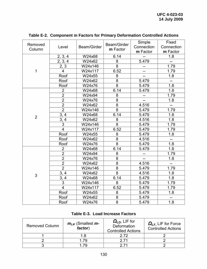
UFC 4-023-03 14 July 2009
130
Table E-2. Component m Factors for Primary Deformation Controlled Actions
Removed Column Level Beam/Girder Beam/Girder
m Factor
Simple Connection m Factor
Fixed Connection m Factor
1
2, 3, 4 W24x68 6.14 -- 1.8 2, 3, 4 W24x62 8 5.479 --
2, 3 W24x146 8 -- 1.79 4 W24x117 6.52 -- 1.79
Roof W24x55 8 -- 1.8 Roof W24x62 8 5.479 -- Roof W24x76 8 5.479 1.8
2
2 W24x68 6.14 5.479 1.8 2 W24x94 8 -- 1.79 2 W24x76 8 -- 1.8 2 W24x62 8 4.516 -- 2 W24x146 8 5.479 1.79
3, 4 W24x68 6.14 5.479 1.8 3, 4 W24x62 8 4.516 1.8 3 W24x146 8 5.479 1.79 4 W24x117 6.52 5.479 1.79
Roof W24x55 8 5.479 1.8 Roof W24x62 8 4.516 -- Roof W24x76 8 5.479 1.8
3
2 W24x68 6.14 5.479 1.8 2 W24x94 8 -- 1.79 2 W24x76 8 -- 1.8 2 W24x62 8 4.516 -- 2 W24x146 8 5.479 1.79
3, 4 W24x62 8 4.516 1.8 3, 4 W24x68 6.14 5.479 1.8 3 W24x146 8 5.479 1.79 4 W24x117 6.52 5.479 1.79
Roof W24x55 8 5.479 1.8 Roof W24x62 8 5.479 -- Roof W24x76 8 5.479 1.8
Table E-3. Load Increase Factors
Removed Column mLIF (Smallest m-factor)
ΩLD, LIF for Deformation
Controlled Actions
ΩLF, LIF for Force Controlled Actions
1 1.8 2.72 2 2 1.79 2.71 2 3 1.79 2.71 2

UFC 4-023-03 14 July 2009
131
E-3.4 Alternate Path Analysis.
The software used for this example was SAP 2000NL. The details of this example can be generally applied in any structural software capable of nonlinear static analysis. The “Staged Construction” option in SAP was used to ensure proper redistribution of loads upon member removal. Comparable software should also have the capability of load redistribution, or loads must be redistributed manually.
E-3.4.1 Develop Preliminary Model.
See Figure E-4 for a model developed in SAP2000. Gravity beams not on column lines are not modeled.
Figure E-4. Isometric View of SAP Model
E-3.4.2 Assign Groups.
Assign each column that is to be removed to a separate group. In this example, removal of three columns is demonstrated, each supporting the first elevated level. Columns are removed at three plan locations, one at a time.

UFC 4-023-03 14 July 2009
132
E-3.4.3 Define Load Cases and Assign Loads.
In addition to load cases required for traditional analysis, load cases must be added for lateral stability effects and to account for the LIF at appropriate locations. Lateral loads are assigned at each level based on the gravity loads applied. Separate load cases are defined for each perpendicular plan direction.
Since increased loads are only applied over the location of the removed column, separate load cases are needed to assign the increased loading over each element to be removed. Separate models are needed to check force controlled actions and deformation controlled actions because of different LIFs.
E-3.4.4 Define Analysis Cases.
The “Staged Construction” option in SAP allows for the creation of separate analysis cases to automate the removal of columns. Create analysis cases which capture the stiffness for column removal. To do this, click Staged Construction button. In stage 1 add ALL, in stage 2 remove the column under investigation. Using these staged construction analysis cases as the initial stiffness, add a new analysis case for each column being removed and for each lateral load direction. For this example, 12 analysis cases were defined (Col1-L2-Xp, Col1-L2-Xn, Col1-L2-Yp, Col1-L2-Yn, Col2-L2-Xp, Col2-L2-Xn, Col2-L2-Yp, Col2-L2-Yn, Col3-L2-Xp, Col3-L2-Xn, Col3-L2-Yp, Col3-L2-Yn,). Only three columns were being removed, but there were four different lateral load directions to be used in the load combination. Within these analysis cases, assign all loads to be used in this analysis case per the load combinations in Equation 3-9 and 3-10. Click Nonlinear parameters button and choose P-delta option. It is possible to use P-delta + large displacements, but it is not necessarily needed for this analysis. Figure E-5 shows a screenshot of the interface for definition of analysis cases and their assigned loads.

UFC 4-023-03 14 July 2009
133
Figure E-5. Analysis Case Definition
E-3.4.5 Define Design Combinations.
In order to use the SAP design procedures to evaluate acceptance criteria design combinations must be defined. Create a design combination for each analysis case (12 total design cases created in this example, additional cases would be required for column removal at other elevations).
E-3.4.6 Run Analysis.
It is important to check that both stages of every analysis case converge. If the analysis does not converge, there is a problem with the model and it must be fixed.
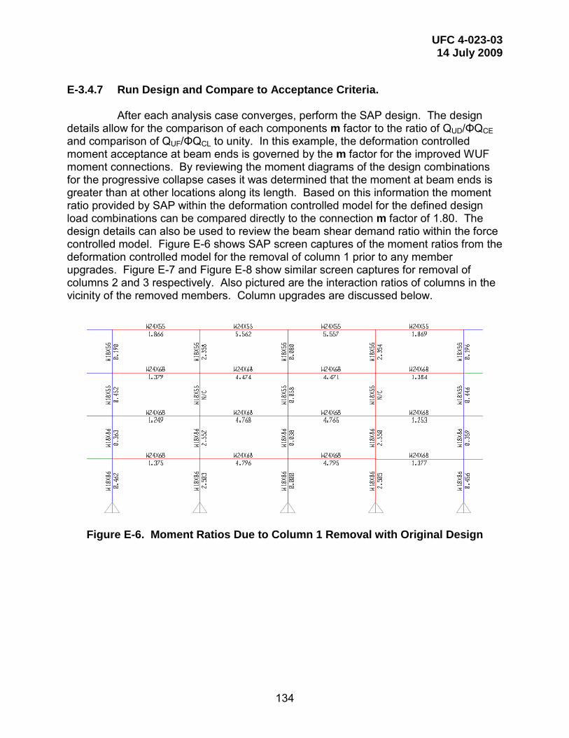
UFC 4-023-03 14 July 2009
134
E-3.4.7 Run Design and Compare to Acceptance Criteria.
After each analysis case converges, perform the SAP design. The design details allow for the comparison of each components m factor to the ratio of QUD/ΦQCE and comparison of QUF/ΦQCL to unity. In this example, the deformation controlled moment acceptance at beam ends is governed by the m factor for the improved WUF moment connections. By reviewing the moment diagrams of the design combinations for the progressive collapse cases it was determined that the moment at beam ends is greater than at other locations along its length. Based on this information the moment ratio provided by SAP within the deformation controlled model for the defined design load combinations can be compared directly to the connection m factor of 1.80. The design details can also be used to review the beam shear demand ratio within the force controlled model. Figure E-6 shows SAP screen captures of the moment ratios from the deformation controlled model for the removal of column 1 prior to any member upgrades. Figure E-7 and Figure E-8 show similar screen captures for removal of columns 2 and 3 respectively. Also pictured are the interaction ratios of columns in the vicinity of the removed members. Column upgrades are discussed below.
Figure E-6. Moment Ratios Due to Column 1 Removal with Original Design

UFC 4-023-03 14 July 2009
135
Figure E-7. Moment Ratios Due to Column 2 Removal with Original Design
Figure E-8. Moment Ratios Due to Column 3 Removal with Original Design

UFC 4-023-03 14 July 2009
136
Figures E-9 through E-11 show SAP screen captures of the moment ratios after member upgrade for the removal of columns 1 through 3 respectively.
Figure E-9. Moment Ratios Due to Column 1 Removal with Redesign
Figure E-10. Moment Ratios Due to Column 2 Removal with Redesign

UFC 4-023-03 14 July 2009
137
Figure E-11. Moment Ratios Due to Column 3 Removal with Redesign
To determine the acceptability of columns, the deformation controlled model
is reviewed to determine the level of axial load. In accordance with ASCE 41, any column with an axial load ratio of greater than or equal to 0.5 must be checked using the model for force controlled actions. These force controlled columns must have interaction values that do not exceed 1. Using the force controlled model, column sizes are increased to reduce interaction values less than unity or to reduce the axial demand in order to evaluate the column as deformation controlled.
Deformation controlled columns (axial load ratio less than 0.5) are checked using the acceptance criteria from ASCE 41. An example calculation for this verification of acceptance is shown in Table E-4.
Table E-4. Deformation Controlled Column Calculations Removed Column 1
Column Size W18x106 P/ΦPn 0.49 8/9 M/ΦMn 0.59 m = 9 (1-5/3 P/Pcl) ASCE 41 Table 5-5 m = 9 (1-5/3 x 0.49 x 0.9) 2.385 Interaction = P/ΦPn + (8/9 M/ΦMn)/m 0.49 + 0.59/2.385 =0.73 OK

UFC 4-023-03 14 July 2009
138
E-3.4.8 Secondary Component Checks.
After verifying that all primary members are capable of resisting progressive collapse, secondary members must be checked against their acceptance criteria from ASCE 41. In this example, simple shear tab connections are assumed for connection of all secondary members. The relative deflection of each end of the secondary member is divided by the length of the beam to determine the chord rotation for the connection. Using this connection rotation and the stiffness of the partially restrained shear tab connection as calculated by Equation 5-15 from ASCE 41, a moment demand can be determined. This moment demand can be compared to the calculated connection moment capacity and the resulting ratio is compared to the connection m factor. The m factors for the secondary member shear tab connections are provided in Table E-5 and are based on UFC Table 5-1. Table E-6 summarizes the calculations required to verify secondary member acceptance. Note that 1.0 is subtracted from the m-factor in the last column in Table E-6, to account for the initial deformations and stresses created by the gravity load, before the column is removed.
Connection shear capacity under force controlled actions (with a LIF = 2)
must be verified. In this example shear demand increased when considering column removal, and an increase in shear connection capacity is required. Table E-5 incorporates the final shear connection configuration, and Table E-6 includes final connection moment capacities determined as the maximum shear capacity multiplied by the maximum eccentricity allowed (3”).
Table E-5. Component m Factors for Secondary Deformation Controlled Actions
Removed Column Beam at Connection Dbg, in Connection m Factor
1 W21x44 6 7.734 2 W21x44 6 7.734 3 W16x31 6 7.734
Table E-6. Secondary Deformation Controlled Actions Acceptance Calculations
Removed Column
Simple Connection
Moment Capacity
Stiffness Relative Deflection
Rotation Demand
Required Moment Capacity
Ratio m-
Factor -1
-- (k-in) (k-in/rad) (in) (rad) (k-in) -- -- 1 237 47400 4.09 0.0077 367.2 1.55 6.734 2 237 47400 0.75 0.0014 67.3 0.28 6.734 3 201 40200 5.52 0.0128 513.7 2.56 6.734
Note that the axial force in these beams and connections are not checked,
due to the small displacements at the ends of the beams. Similarly, the concrete slab is not checked, based on the small rotations and engineering judgment.

UFC 4-023-03 14 July 2009
139
E-3.5 Enhanced Local Resistance.
Enhanced local resistance provisions for Occupancy Category III require that all perimeter columns at the first floor above grade achieve shear capacities associated with the shear demand required to achieve the enhanced flexural resistance of the columns. For Occupancy Category III, the enhanced flexural resistance is equal to the flexural resistance determined through the alternate path procedure. For the purposes of ELR evaluation, the columns are considered fixed at the first level and pinned at the base. For this example, the required shear resistance is based on these boundary conditions and is defined by Equation E-1 for shear on a column that is fixed at one end and pinned at the other. Vu = 7.5 Mp / L Equation (E-1) where Vu = Required shear strength
Mp = Column moment capacity accounting for axial load. L = Column height
In this example, shear strength for all columns other than corner columns exceeds this value so no member size increases were required beyond those determined using the alternate path procedure. For corner columns there is no W18 section that can provide adequate shear strength to develop the required strong axis moment. In order to satisfy these provisions, web doubler plates were added. At these corner locations the axial load is less than 10% of the column capacity so it was ignored.
The corner column is a W18x97 with a strong axis plastic modulus of 211 in3 per Figure E-11. The required shear resistance (per equation E-1) and capacity (per AISC Chapter G) are determined as follows:
Vu = 7.5 Mp / L = 7.5 * 55 ksi * 211 in3 / 174 in = 495 kips Vn = 0.6 tw h Fy= 0.6 * 0.535 in * 16.06 in * 55 ksi = 283 kips
Accounting for the increased flexural capacity due to the added plate, a 5/8”
thick doubler plate is required for all corner columns. See Figure E-12 for a diagram of the doubler plate used to enhance strong axis shear strength.
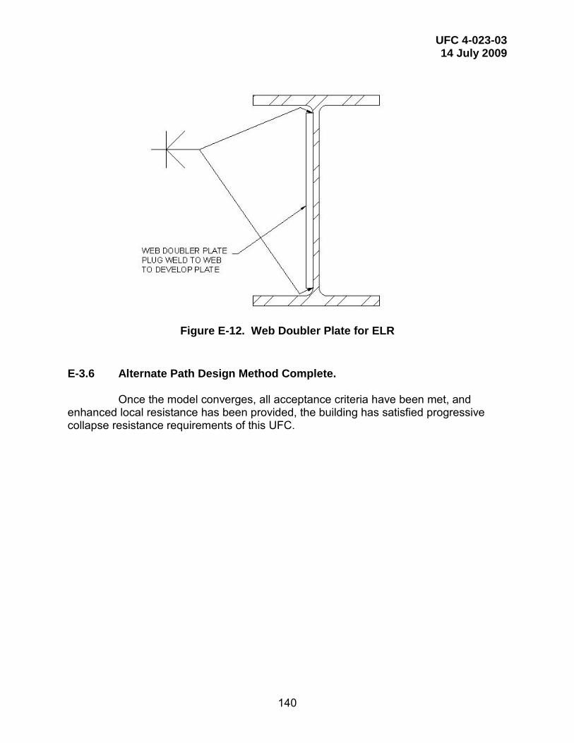
UFC 4-023-03 14 July 2009
140
Figure E-12. Web Doubler Plate for ELR
E-3.6 Alternate Path Design Method Complete.
Once the model converges, all acceptance criteria have been met, and enhanced local resistance has been provided, the building has satisfied progressive collapse resistance requirements of this UFC.

UFC 4-023-03 14 July 2009
141
E-4 NON LINEAR DYNAMIC PROCEDURE (NDP).
Locations of required columns removals are illustrated in Figure E-14. Each removal is considered separately. For the purpose of this example, the column below level 2 is removed, Section 3-2 requires additional analyses for removals at other levels.
Figure E-13. Column Removal Locations
E-4.1 DCR and Irregularity Limitations.
There are no DCR or geometric irregularity limitations on the use of the NDP.
E-4.2 Alternate Path Analysis.
The software used and screen shots depicted for this example was SAP 2000NL. The details of this example can be generally applied in any structural software capable of nonlinear static analysis. The “Staged Construction” option in SAP was used to ensure proper redistribution of loads upon member removal. Comparable software should also have the capability of load redistribution, or loads must be redistributed manually.
E-4.2.1 Develop Preliminary Model.
See Figure E-14 for a model developed in SAP2000. All beams and columns are modeled including gravity beams.
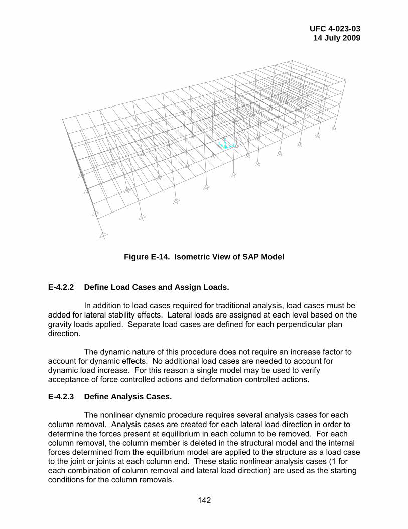
UFC 4-023-03 14 July 2009
142
Figure E-14. Isometric View of SAP Model
E-4.2.2 Define Load Cases and Assign Loads.
In addition to load cases required for traditional analysis, load cases must be added for lateral stability effects. Lateral loads are assigned at each level based on the gravity loads applied. Separate load cases are defined for each perpendicular plan direction.
The dynamic nature of this procedure does not require an increase factor to
account for dynamic effects. No additional load cases are needed to account for dynamic load increase. For this reason a single model may be used to verify acceptance of force controlled actions and deformation controlled actions.
E-4.2.3 Define Analysis Cases.
The nonlinear dynamic procedure requires several analysis cases for each column removal. Analysis cases are created for each lateral load direction in order to determine the forces present at equilibrium in each column to be removed. For each column removal, the column member is deleted in the structural model and the internal forces determined from the equilibrium model are applied to the structure as a load case to the joint or joints at each column end. These static nonlinear analysis cases (1 for each combination of column removal and lateral load direction) are used as the starting conditions for the column removals.

UFC 4-023-03 14 July 2009
143
Within these analysis cases, assign all loads to be used in this analysis case
per the load combinations in Equation 3-19. Click Nonlinear parameters button and choose P-delta option. It is possible to use P-delta + large displacements, but it is not necessarily needed for this analysis. Figure E-15 shows a screenshot of the interface for definition of analysis cases and their assigned loads.
Figure E-15. Analysis Case Definition
After equilibrium is reached for the structure, remove the column by ramping
down the column forces under a duration for removal of less than one tenth of the period associated with the structural response mode for the element removal. The analysis shall continue until the maximum displacement is reached or one cycle of vertical motion occurs at the column or wall section removal location. Figure E-16 shows a screen shot of the column removal analysis case definition. Four such analysis cases are needed for each column removal location (1 for each lateral load direction).

UFC 4-023-03 14 July 2009
144
Figure E-16. Analysis Case Definition
E-4.2.4 Define Design Combinations.
SAP design procedures may be used to evaluate whether columns are deformation or force controlled. Design checks also aid in the definitions of column hinges by determining axial load demand and capacity. Create a design combination for each analysis case (12 total design cases created in this example, additional cases would be required for column removal at other elevations).

UFC 4-023-03 14 July 2009
145
E-4.2.5 Run Dynamic Analysis.
It is important to check that both stages of every analysis case converge. If the analysis does not converge, there is a problem with the model and it must be fixed. The problem could be numerical with assumptions made in SAP, but the most likely reason is that the model has a plastic hinge that failed or a mechanism has formed. At this point, the model cannot support the load.
E-4.2.6 Plastic Hinges.
For the nonlinear alternate load path method, plastic hinges are allowed to form along the members. These hinges are based on maximum moment values calculated using phi factors and over-strength factors per the UFC. However, only flexural moments can cause a plastic hinge to form in beam members, and only the axial-moment interaction (PMM) can cause a plastic hinge to form in a column. Any shear or torsion values that would cause a hinge to form would result in an immediate failure.
E-4.2.7 Hinge Locations.
Theoretically hinges can occur anywhere along the beam. However, hinges are allowed to occur at the ends of each member and at the midspan of the flexural members. This simplifies the model by placing hinges in the most probable locations.
E-4.2.8 Hinge Properties.
Nonlinear acceptance criteria and component definitions are from Chapter 5 of ASCE 41 for the Life Safety condition for primary and secondary components. Use the modeling parameters and guidance, including definitions of stiffness, to create the analytical model. For beams subjected to flexure or flexure plus axial tension, use the Collapse Prevention values for primary and secondary elements. For the Fully Restrained (FR) and Partially Restrained (PR) connections listed in Tables 5-1 and 5-2 in this UFC, use the specified plastic rotations and modeling parameters as given. Figure E-17 shows the form of the plastic hinges for this model.
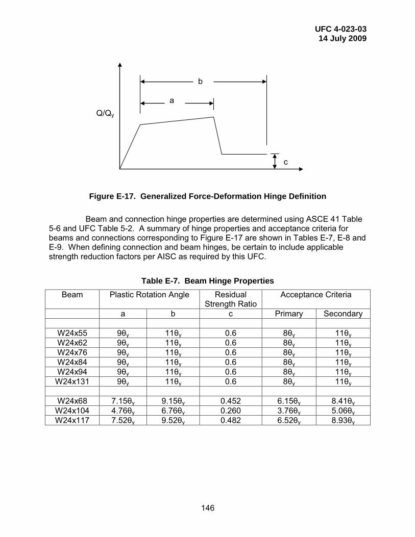
UFC 4-023-03 14 July 2009
146
Figure E-17. Generalized Force-Deformation Hinge Definition
Beam and connection hinge properties are determined using ASCE 41 Table
5-6 and UFC Table 5-2. A summary of hinge properties and acceptance criteria for beams and connections corresponding to Figure E-17 are shown in Tables E-7, E-8 and E-9. When defining connection and beam hinges, be certain to include applicable strength reduction factors per AISC as required by this UFC.
Table E-7. Beam Hinge Properties Beam Plastic Rotation Angle Residual
Strength Ratio Acceptance Criteria
a b c Primary Secondary
W24x55 9θy 11θy 0.6 8θy 11θy W24x62 9θy 11θy 0.6 8θy 11θy W24x76 9θy 11θy 0.6 8θy 11θy W24x84 9θy 11θy 0.6 8θy 11θy W24x94 9θy 11θy 0.6 8θy 11θy
W24x131 9θy 11θy 0.6 8θy 11θy
W24x68 7.15θy 9.15θy 0.452 6.15θy 8.41θy W24x104 4.76θy 6.76θy 0.260 3.76θy 5.06θy W24x117 7.52θy 9.52θy 0.482 6.52θy 8.93θy
Q/Qy
c
b
a

UFC 4-023-03 14 July 2009
147
Table E-8. Fully Restrained Connection Hinge Properties
Beam Depth Plastic Rotation Angle Residual Strength
Ratio
Acceptance Criteria
a b c Primary (in) (rad) (rad) (rad)
(0.021-0.0003D) (0.05-0.0006D) (0.021-0.0003D)
W24x55 23.6 0.01392 0.03584 0.2 0.01392 W24x62 23.7 0.01389 0.03578 0.2 0.01389 W24x68 23.7 0.01389 0.03578 0.2 0.01389 W24x76 23.9 0.01383 0.03566 0.2 0.01383 W24x84 24.1 0.01377 0.03554 0.2 0.01377 W24x94 24.3 0.01371 0.03542 0.2 0.01371
W24x104 24.1 0.01377 0.03554 0.2 0.01377 W24x117 24.3 0.01371 0.03542 0.2 0.01371 W24x131 24.5 0.01365 0.03530 0.2 0.01365

UFC 4-023-03 14 July 2009
148
Table E-9. Shear Tab Partially Restrained Connection Hinge Properties
Beam Dbg Vmax Mcapacity Plastic Rotation Angle Residual Strength
Ratio Acceptance Criteria
a b c Primary Secondary (in) (kips) (kip-in) (rad) (rad) (rad) (rad) (0.0502-0.0015D) (0.072-0.0022D) (0.0502-0.0015D) (0.0503-0.0011D) W16x31 6 56 168 0.0412 0.0588 0.2 0.0412 0.0437 W16x31 (R) 3 32 96 0.0457 0.0654 0.2 0.0457 0.0470 W21x44 6 67 201 0.0412 0.0588 0.2 0.0412 0.0437 W21x44 (R) 3 32 96 0.0457 0.0654 0.2 0.0457 0.0470 W24x55 (R) 3 32 96 0.0457 0.0654 0.2 0.0457 0.0470 W24x62 12 126 378 0.0322 0.0456 0.2 0.0322 0.0371 W24x62 (R) 3 32 96 0.0457 0.0654 0.2 0.0457 0.0470 W24x68 3 55 165 0.0457 0.0654 0.2 0.0457 0.0470 W24x84 3 32 96 0.0457 0.0654 0.2 0.0457 0.0470 W24x94 3 55 165 0.0457 0.0654 0.2 0.0457 0.0470 W24x104 3 55 165 0.0457 0.0654 0.2 0.0457 0.0470

UFC 4-023-03 14 July 2009
149
Column hinge properties are determined using ASCE 41 Table 5-6. These hinge definitions are dependent on the level of axial load present in the member. Because the hinge properties are based on the level of force present, they must be updated when the force level changes significantly. The initial model run was used for preliminary definitions of column hinges. A summary of hinge properties and acceptance criteria for columns used in this example corresponding to Figure E-17 are shown in Tables E-10, E-11 and E-12.
Table E-10. Column Hinge Properties for Removal of Column 1 Column P/Pcl Plastic Rotation Angle Residual
Strength Ratio
Acceptance Criteria
a b c Primary (rad) (rad) (rad)
W18x40 0.12 0.0504 0.0623 0.557 0.0332 W18x40 0.42 0.0118 0.0189 0.2 0.0159
W18x76 0.09 0.0425 0.0554 0.406 0.0262 W18x76 0.12 0.0352 0.0471 0.349 0.0209 W18x76 0.19 0.0323 0.0433 0.349 0.0192 W18x76 0.21 0.0278 0.0423 0.2 0.0121 W18x76 0.38 0.0169 0.0257 0.2 0.0059
W18x86 0.17 0.0474 0.0586 0.557 0.0312
W18x106 0.24 0.0331 0.0511 0.2 0.0241 W18x106 0.27 0.0296 0.0458 0.2 0.0216 W18x106 0.35 0.0197 0.0305 0.2 0.0144 W18x106 0.39 0.0158 0.0244 0.2 0.0115

UFC 4-023-03 14 July 2009
150
Table E-11. Column Hinge Properties for Removal of Column 2 Column P/Pcl Plastic Rotation Angle Residual
Strength Ratio
Acceptance Criteria
a b c Primary (rad) (rad) (rad)
W18x50 0.05 0.0530 0.0664 0.512 0.0470 W18x50 0.15 0.0471 0.0591 0.512 0.0418 W18x50 0.19 0.0451 0.0565 0.512 0.0400
W18x60 0.06 0.0590 0.0721 0.6 0.0393 W18x60 0.13 0.0545 0.0667 0.6 0.0364 W18x60 0.27 0.0252 0.0384 0.2 0.0117 W18x60 0.40 0.0160 0.0244 0.2 0.0063
W18x76 0.04 0.0384 0.0515 0.349 0.0229 W18x76 0.06 0.0376 0.0504 0.349 0.0224 W18x76 0.19 0.0323 0.0433 0.349 0.0192 W18x76 0.27 0.0236 0.0359 0.2 0.0097
W18x86 0.09 0.0521 0.0644 0.557 0.0343 W18x86 0.11 0.0509 0.0629 0.557 0.0335 W18x86 0.13 0.0500 0.0618 0.557 0.0329
W18x97 0.17 0.0499 0.0610 0.6 0.0333 W18x97 0.23 0.0345 0.0533 0.2 0.0251 W18x97 0.25 0.0322 0.0498 0.2 0.0234 W18x97 0.37 0.0182 0.0281 0.2 0.0132
W18x106 0.24 0.0333 0.0514 0.2 0.0242 W18x106 0.34 0.0208 0.0321 0.2 0.0151 W18x106 0.35 0.0198 0.0305 0.2 0.0144 W18x106 0.49 0.0067 0.0104 0.2 0.0049

UFC 4-023-03 14 July 2009
151
Table E-12. Column Hinge Properties for Removal of Column 3 Column P/Pcl Plastic Rotation Angle Residual
Strength Ratio Acceptance
Criteria a b c Primary (rad) (rad) (rad)
W18x50 0.05 0.0530 0.0664 0.512 0.0470 W18x50 0.14 0.0477 0.0598 0.512 0.0423 W18x50 0.19 0.0451 0.0566 0.512 0.0400 W18x50 0.41 0.0157 0.0239 0.2 0.0060
W18x60 0.06 0.0590 0.0722 0.6 0.0394 W18x60 0.14 0.0537 0.0657 0.6 0.0358 W18x60 0.27 0.0252 0.0384 0.2 0.0117 W18x60 0.40 0.0161 0.0245 0.2 0.0063
W18x86 0.11 0.0508 0.0628 0.557 0.0334 W18x86 0.16 0.0480 0.0593 0.557 0.0316 W18x86 0.23 0.0334 0.0515 0.2 0.0229 W18x86 0.35 0.0202 0.0311 0.2 0.0135
W18x97 0.18 0.0498 0.0608 0.6 0.0332 W18x97 0.24 0.0340 0.0526 0.2 0.0248 W18x97 0.35 0.0202 0.0312 0.2 0.0147
E-4.2.9 Iterate Dynamic Analysis.
It is important to check that both stages of every analysis case converge. If the analysis does not converge, there is a problem with the model and it must be fixed. The problem could be numerical with assumptions made in SAP, but the most likely reason is that the model has a plastic hinge that failed or a mechanism has formed. At this point, the model cannot support the load. If the analysis fails to converge,
1) Since the analysis did not converge, members must be redesigned. To determine which members must be redesigned, step through the incomplete progression of plastic hinge formations. The final steps saved by SAP will often give the best results on which beams or columns to redesign. See Figure E-18 for the final step in the hinge formations of an analysis that did not converge. 2) To view the plastic hinges, click Display – Deformed Shape. Choose an analysis case and click to the last step of that case. Any hinge that forms will “light up,” and its color denotes the region the hinge has progressed (see Figure E-17). A hinge deformed in excess of the limit defined by its acceptance criteria, or is orange or red has failed.
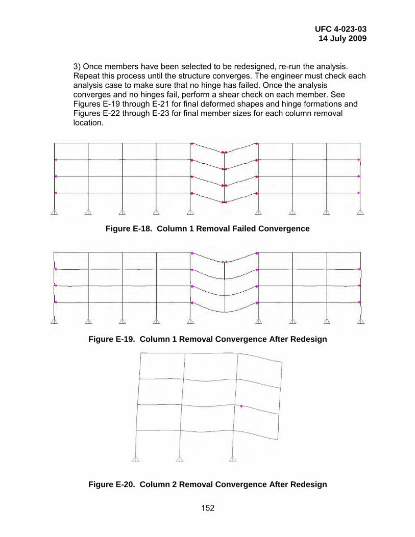
UFC 4-023-03 14 July 2009
152
3) Once members have been selected to be redesigned, re-run the analysis. Repeat this process until the structure converges. The engineer must check each analysis case to make sure that no hinge has failed. Once the analysis converges and no hinges fail, perform a shear check on each member. See Figures E-19 through E-21 for final deformed shapes and hinge formations and Figures E-22 through E-23 for final member sizes for each column removal location.
Figure E-18. Column 1 Removal Failed Convergence
Figure E-19. Column 1 Removal Convergence After Redesign
Figure E-20. Column 2 Removal Convergence After Redesign

UFC 4-023-03 14 July 2009
153
Figure E-21. Column 3 Removal Convergence After Redesign
Figure E-22. Typical Member Sizes After Redesign for Column 1 Removal

UFC 4-023-03 14 July 2009
154
Figure E-23. Typical Member Sizes After Redesign for Column 2 or 3 Removal
E-4.2.10 Secondary Component Checks.
Because the gravity beams were explicitly included in the model, there are no secondary components to check. As with the Linear Static solution, the slab is adequate due to the small deformations and by engineering judgment.
E-4.3 Enhanced Local Resistance.
Enhanced local resistance provisions for Occupancy Category III require that all perimeter columns at the first floor above grade achieve shear capacities associated with the shear demand required to achieve the enhanced flexural resistance of the columns. For Occupancy Category III, the enhanced flexural resistance is equal to the flexural resistance determined through the alternate path procedure. For the purposes of ELR evaluation, the columns are considered fixed at the first level and pinned at the base. For this example, the required shear resistance is defined by Equation E-1. Vu = 7.5 Mp / L Equation (E-1)

UFC 4-023-03 14 July 2009
155
where Vu = Required shear strength
Mp = Column moment capacity accounting for axial load. L = Column height
In this example, shear strength for all columns other than corner columns exceeds this value so no member size increases were required beyond those determined using the alternate path procedure. For corner columns there is no W18 section that can provide adequate shear strength to develop the required strong axis moment. In order to satisfy these provisions web doubler plates were added. At these corner locations the axial load is less than 10% of the column capacity so it was ignored. Accounting for the increased flexural capacity due to the added plate, a 1/2” thick doubler plate is required for all corner columns. See Figure E-12 for a diagram of the doubler plate provided to enhance strong axis shear resistance.
E-4.4 Alternate Path Design Method Complete.
Once the model converges, all acceptance criteria have been met, and enhanced local resistance has been provided, the building has satisfied progressive collapse resistance requirements of this UFC.
E-5 RESULTS COMPARISON.
Member size requirements determined from the linear static and nonlinear dynamic procedures are presented and compared to original size requirements in Tables E-13 and E-14.
Table E-13. Moment Frame Size Comparison Location Level Original Size LSP AP Size NDP AP Size
Long Side 2 W24x68 W24x146 W24x104 Long Side 3 W24x68 W24x146 W24x104 Long Side 4 W24x68 W24x117 W24x94 Long Side Roof W24x55 W24x76 W24x62
Short Side – Exterior 2 W24x94 W24x94 W24x94 Short Side – Exterior 3 W24x62 W24x68 W24x62 Short Side – Exterior 4 W24x62 W24x68 W24x62 Short Side – Exterior Roof W24x55 W24x55 W24x55
Short Side – Central 2 W24x76 W24x104 W24x76 Short Side – Central 3 W24x68 W24x104 W24x68 Short Side – Central 4 W24x68 W24x94 W24x68 Short Side – Central Roof W24x55 W24x55 W24x55

UFC 4-023-03 14 July 2009
156
Table E-14. Perimeter Column Size Comparison Location Level Original Size LSP AP Size NDP AP Size
Long Side – Interior 1-3 W18x86 W18x175 W18x106 Long Side – Interior 3-Roof W18x55 W18x106 W18x76
Short Side – Interior 1-3 W18x97 W18x119 W18x97 Short Side – Interior 3-Roof W18x60 W18x76 W18x60
Corner 1-3 W18x86 W18x97 W18x86 Corner 3-Roof W18x40 W18x76 W18x50
The frame size increases required for progressive collapse resistance are
summarized by total weight in Table E-15. The weight of the exterior moment frames (girders and columns) are reported for the long side and short side for the baseline design, and after providing progressive collapse resistance using each of the linear static and non linear dynamic procedures.
Table E-15. Frame Weight Comparison Frame Original Weight LSP AP Weight NDP AP Weight
(tons) (tons) (tons)
Long Side 58.2 108.7 78.2 Short Side 20.1 24.5 20.4

UFC 4-023-03 14 July 2009
157
APPENDIX F WOOD EXAMPLE
F-1 INTRODUCTION. A wood load-bearing wall structure example has been prepared to illustrate
Alternate Path analysis of a bearing wall type structure. The structure is assumed to have an occupancy of less than 100 people and is classified as Occupancy Category II per \1\ UFC 3-301-01 /1/.
The example has been prepared using tools and techniques commonly
applied by structural engineering firms in the US. For wood design, this example relies primarily upon hand analysis supplemented with standard design tables published by various wood organizations. Occupancy Category II Option 2: Alternate Path has been selected from UFC Table 2-2 to evaluate resistance to progressive collapse.
F-2 BASELINE DESIGN.
The example building is a 3-story wood structure, six bays long and two bays deep. The relevant design information is shown in Figures F-1 through F-4.
Platform construction is used. The internal shear walls are load bearing, with
engineered I-joists (EIJ) running in the direction of the long length of the structure. One 4.5-foot x 6-foot window opening is present in each room. The footings are reinforced concrete with masonry. There are no internal partition walls.

UFC 4-023-03 14 July 2009
158
Figure F-1. Wood Example Plan

UFC 4-023-03 14 July 2009
159
Figure F-2. Wood Example Wall Section

UFC 4-023-03 14 July 2009
160
Figure F-3. Wood Example Exterior Wall Elevation [

UFC 4-023-03 14 July 2009
161
Figure F-4. Wood Example Building Section
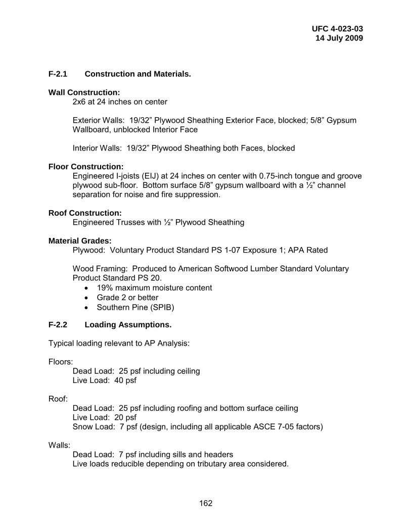
UFC 4-023-03 14 July 2009
162
F-2.1 Construction and Materials. Wall Construction:
2x6 at 24 inches on center Exterior Walls: 19/32” Plywood Sheathing Exterior Face, blocked; 5/8” Gypsum Wallboard, unblocked Interior Face Interior Walls: 19/32” Plywood Sheathing both Faces, blocked
Floor Construction:
Engineered I-joists (EIJ) at 24 inches on center with 0.75-inch tongue and groove plywood sub-floor. Bottom surface 5/8” gypsum wallboard with a ½” channel separation for noise and fire suppression.
Roof Construction:
Engineered Trusses with ½” Plywood Sheathing Material Grades:
Plywood: Voluntary Product Standard PS 1-07 Exposure 1; APA Rated Wood Framing: Produced to American Softwood Lumber Standard Voluntary Product Standard PS 20.
• 19% maximum moisture content • Grade 2 or better • Southern Pine (SPIB)
F-2.2 Loading Assumptions. Typical loading relevant to AP Analysis: Floors:
Dead Load: 25 psf including ceiling Live Load: 40 psf
Roof:
Dead Load: 25 psf including roofing and bottom surface ceiling Live Load: 20 psf Snow Load: 7 psf (design, including all applicable ASCE 7-05 factors)
Walls:
Dead Load: 7 psf including sills and headers Live loads reducible depending on tributary area considered.

UFC 4-023-03 14 July 2009
163
F-2.3 Relevant Standards and Reference Documents. ANSI/AF&PA NDS-2005 National Design Specification for Wood Construction ASD/LRFD ANSI/AF&PA SDPWS-2005 ASD/LRFD Special Design Provisions for Wind and Seismic With Commentary International Building Code 2006 For design compatible with the UFC document LRFD is followed.
F-3 ALTERNATE PATH ANALYSIS.
An alternate path (AP) analysis will be conducted according to the requirements of Section 3-2. Removal scenarios are defined by 3-2.9.2.2. To bridge the wall removals, the remaining load bearing walls will be utilized as shear wall elements. The linear static AP analysis method will be followed.
F-3.1 Scope and Analysis Assumptions.
While 3-2.9.2.2 requires removal of each 2H section of wall, for illustrative purposes two scenarios of wall removal will be evaluated:
1. Removal of interior load-bearing wall (see Figure F-5) at first story 2. Removal of exterior long walls (see Figure F-6) at second story
General assumptions of the analysis are as follows:
• No wind or internal pressure acts on interior or exterior walls during wall removal scenario
• Contributions of EIJ and engineered roof trusses to the alternate path capacity are neglected due to uncertainty in specific properties during the design phase. At the designers option these elements could be included provided appropriate performance specifications including AP requirements are incorporated into the contract documents.
Per ASCE 41-06
• C8.2.2.5: “Actions associated with wood and light metal framing components generally are deformation controlled, and expected strength material properties will be used most often.”
• 8.3.3: “Demands on connectors, including nails, screws, lags, bolts, split rings, and shear plates used to link wood components to other wood or metal components shall be considered deformation controlled actions. Demands on bodies of connections, and bodies of connection hardware, shall be considered force-controlled actions.”

UFC 4-023-03 14 July 2009
164
For the AP analysis of this structure, wood shear wall assemblies and primary connections will be taken to be deformation controlled elements. Bodies of connectors will be checked as force controlled elements as required.
F-3.2 AP Analysis of Interior Load Bearing Wall Removal.
Figure F-5. Interior Load Bearing Wall Removal
As shown in Figure F-5, a segment of wall of length 2H is removed from the lower floor interior load bearing wall. H is taken as the distance between the 1st floor sub-floor elevation and the bottom of the 11-7/8” EIJ floor joists at the 2nd floor (=10’-1¼”).
The remaining structure creates a shear wall element that must span the floor
and wall loads from the 2nd and 3rd stories. The shear wall is taken to have an overall depth of 17’-6 5/8” (2nd floor to truss bearing). The boundary (chord) elements consist of (2) 2x6 plates provided at the top and bottom of each wall.
To bridge the removed section of wall the shear wall panel must span from
the exterior wall to a wall pier segment consisting of the remaining portion of the removed lower story interior wall. Note that no continuity action that might engage the right-hand wall panels in Figure F-5 is possible due to the corridor opening.
The structure contains no irregularities and therefore the linear static AP
analysis is permitted per Section 3-2.11.1.1.
20’-2½”
10’-1
¼”

UFC 4-023-03 14 July 2009
165
Loading: Dead Load
Floors: 25 psf * 18’-8” * 2 floors = 934 plf Wall: 7 psf * 18’-6 ½” = 130 plf
Live Load
40 psf * 18.67 * 2 floors = 1494 plf Reduce live load in accordance with IBC 2006 1607.9.2:
A = 18.67’*20.21’*2 = 755 SF R = 0.08 (A – 150) = 0.08 (755-150) = 48.4% Rmax = 60% or 23.1(1 + 25/40) = 37.5%
Live load used in AP check = 1494 plf (1-0.375) = 934 plf Linear Static AP Load Case for Deformation Controlled Elements:
GLD = ΩLD [1.2D + 0.5 L] From ASCE 41-06 Table 8-3:
For “Wood Structural Panel Sheathing or Siding” h/b = 17.55/20.21 = 0.87 < 2.0 m = 3.8 for Life Safety Primary Element
Assume all connections to be nailed:
m = 6.0 for “Nails – Wood to Wood” m = 4.0 for “Nails – Wood to Metal”
m = 3.8 controls
ΩLD = 2.0m = 7.6 (UFC Table 3-4) GLD = 7.6*(1.2*(934+130) + 0.5*(934)) = 7.6*(1744 plf) = 13,254 plf
Deformation controlled actions:
Shear: QUD = 13,254 plf * 20.21’ / 2 / 17.55’ = 7,631 plf in wall Capacity checks of deformation controlled actions:
Shear in Wall: Wall shear capacity φQCE = 1.5 (φvs) where φvs = LRFD shear capacity of wall taken from ANSI/AFPA SDPWS-2005 Factor 1.5 for expected strength is taken from ASCE 41-06 8.4.9.2, but note that Para. 3-2.11.7.1 requires inclusion of the material specific φ factor whereas ASCE 41-06 uses a φ of 1.0.

UFC 4-023-03 14 July 2009
166
From ANSI/AFPA SDPWS-2005 Table 4.3A: For “Wood Structural Panels – Sheathing”, 19/32 with 10d nailing at 6” at edges: vwc = 950 plf (for one side of wall) Note that value for wind is chosen rather than seismic per UFC Ch. 7.
Since the interior walls have plywood sheathing on both sides, capacity of each individual side is additive per ANSI/AFPA SDPWS-2005 4.3.3.2. φ = 0.8 for LRFD per ANSI/AFPA SDPWS-2005 4.3.3 φvs = 0.8 (950) (2) = 1520 plf φQCE = 1.5 (φvs) = 1.5 (1520) = 2280 plf Check UFC Equation 3-13:
φmQCE ≥ QUD 2280 plf (3.8) = 8,664 plf > 7,631 plf OK
At the edge of the removed wall segment adjacent to the building exterior, the
interior load bearing wall must transfer its reaction in shear to the exterior wall for distribution to an adequate length of exterior load bearing stud wall.
Exterior Wall Check: QUD = 7,631 plf / 2 = 3,816 plf (half of reaction distributed each direction) From ANSI/AFPA SDPWS-2005 Table 4.3A:
Exterior sheathing plywood 19/32 with 10d nailing at 6” at edges: vwc = 950 plf Interior sheathing 5/8” gypsum wallboard, unblocked, 4” fastener spacing. From Table 4.3B: vwc = 290 plf
The exception found in ANSI/AFPA SDPWS-2005 4.3.3.2.2 allows shear capacities of wood structural panels and gypsum wallboard to be directly combined:
φvs = 0.8 (950 + 290) = 1240 plf φQCE = 1.5 (1240) = 1860 plf
From ASCE 41-06 Table 8-3 m = 4.7 for Gypsum Wallboard with h/b ≤ 1.0. Assuming the shear reaction is spread over a length b less than 17.55’, the m factor for wood structural panel's controls. Check UFC Equation 3-13:
φmQCE ≥ QUD 1860 (3.8) = 7,068 plf > 3,816 plf OK

UFC 4-023-03 14 July 2009
167
For force controlled actions:
ΩLF = 2.0 (UFC Table 3-4) GLF = 2.0*(1.2*(934+130) + 0.5*(934)) = 2.0*(1744 plf) = 3,488 plf
Force controlled actions:
Shear: QUF = 3,488 plf * 20.21’ / 2 / 17.55’ = 2,008 plf in wall Chord Force: QUF = 3,488 plf * 20.212 / (8*17.55) = 10,147 pounds
Though ASCE 41 is somewhat ambiguous on the subject, consider the chord forces to be force controlled actions because ASCE 41 Table 8-3 designates “Frame Components Subject to Axial Compression” as force controlled. Treating both tension and compression chords as force controlled will be conservative.
From the NDS supplement for 2x6 #2 Southern Pine:
Ft = 825 psi Fc = 1650 psi Fc⊥ = 565 psi Emin = 580,000 psi
Chord force limit will be governed by tension capacity since compression chord is fully braced in both directions:
Adjusted reference design value F’t = CMCtCFCiKFφtλFt All adjustment values are 1.0 except:
KF = 2.16/φt φt = 0.80 Note λ = 1.0 for short duration loading event
F’t = 2.16*825 = 1782 psi
φQCL = 1782 psi (8.25 in2) = 14,702 pounds for (1) 2x6 > QUF = 10,147 pounds OK
Note that by providing adequate strength for (1) 2x6 plate to act as a chord, the pair of 2x6’s may be stagger spliced via nailing without the need for a direct metal plate splice of both plates. Nailing for splices should be sized for 10,147 pounds.
Check bearing transfer of bridged load to load bearing stud walls as force controlled action.
QUF = 3,488 plf * 20.21’ / 2 = 35,246 pounds
Check as columns for out-of-plane capacity at lower story. 2x6 studs at 24” on center with in-plane bracing provided by sheathing.
Adjusted reference design value F’c = CMCtCFCiCPKFφcλFc All adjustment values are 1.0 except:
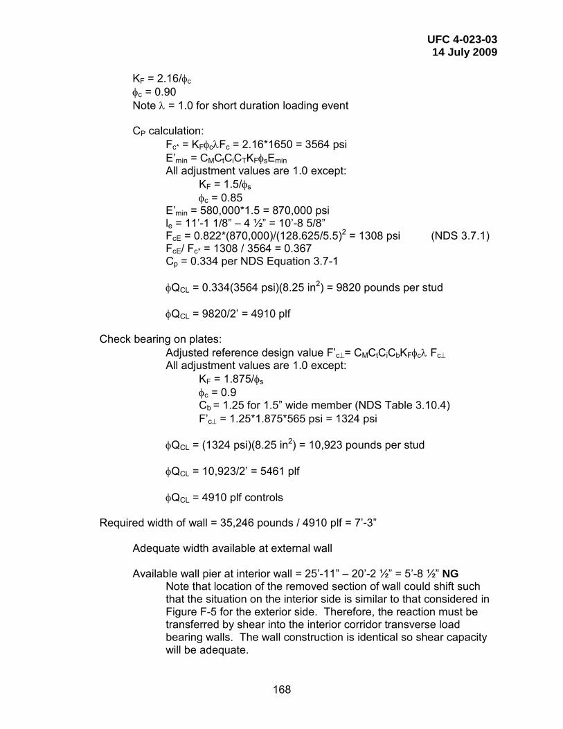
UFC 4-023-03 14 July 2009
168
KF = 2.16/φc φc = 0.90 Note λ = 1.0 for short duration loading event
CP calculation:
Fc* = KFφcλFc = 2.16*1650 = 3564 psi E’min = CMCtCiCTKFφsEmin All adjustment values are 1.0 except:
KF = 1.5/φs φc = 0.85
E’min = 580,000*1.5 = 870,000 psi le = 11’-1 1/8” – 4 ½” = 10’-8 5/8” FcE = 0.822*(870,000)/(128.625/5.5)2 = 1308 psi (NDS 3.7.1) FcE/ Fc* = 1308 / 3564 = 0.367 Cp = 0.334 per NDS Equation 3.7-1 φQCL = 0.334(3564 psi)(8.25 in2) = 9820 pounds per stud φQCL = 9820/2’ = 4910 plf
Check bearing on plates:
Adjusted reference design value F’c⊥= CMCtCiCbKFφcλ Fc⊥ All adjustment values are 1.0 except:
KF = 1.875/φs φc = 0.9 Cb = 1.25 for 1.5” wide member (NDS Table 3.10.4) F’c⊥ = 1.25*1.875*565 psi = 1324 psi
φQCL = (1324 psi)(8.25 in2) = 10,923 pounds per stud φQCL = 10,923/2’ = 5461 plf φQCL = 4910 plf controls
Required width of wall = 35,246 pounds / 4910 plf = 7’-3”
Adequate width available at external wall
Available wall pier at interior wall = 25’-11” – 20’-2 ½” = 5’-8 ½” NG
Note that location of the removed section of wall could shift such that the situation on the interior side is similar to that considered in Figure F-5 for the exterior side. Therefore, the reaction must be transferred by shear into the interior corridor transverse load bearing walls. The wall construction is identical so shear capacity will be adequate.
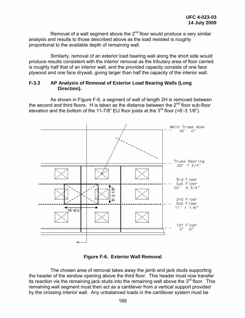
UFC 4-023-03 14 July 2009
169
Removal of a wall segment above the 2nd floor would produce a very similar analysis and results to those described above as the load resisted is roughly proportional to the available depth of remaining wall.
Similarly, removal of an exterior load bearing wall along the short side would
produce results consistent with the interior removal as the tributary area of floor carried is roughly half that of an interior wall, and the provided capacity consists of one face plywood and one face drywall, giving larger than half the capacity of the interior wall.
F-3.3 AP Analysis of Removal of Exterior Load Bearing Walls (Long Direction).
As shown in Figure F-6, a segment of wall of length 2H is removed between
the second and third floors. H is taken as the distance between the 2nd floor sub-floor elevation and the bottom of the 11-7/8” EIJ floor joists at the 3rd floor (=8’-3 1/8”).
Figure F-6. Exterior Wall Removal
The chosen area of removal takes away the jamb and jack studs supporting
the header of the window opening above the third floor. This header must now transfer its reaction via the remaining jack studs into the remaining wall above the 3rd floor. This remaining wall segment must then act as a cantilever from a vertical support provided by the crossing interior wall. Any unbalanced loads in the cantilever system must be
16’-6¼”
8’-3
1/8
”

UFC 4-023-03 14 July 2009
170
resolved via drag forces in the 3rd floor and top of wall sill elements to adjacent intact wall segments. See Figure F-7.
Figure F-7. Load Path for Exterior Wall Removal The primary loading is that of the roof trusses: Dead Load
Roof: 25 psf * 25’-11” / 2 = 324 plf Wall: 7 psf * 8’-3” = 58 plf
Roof live load not applicable for UFC design combination Snow Load
7 psf * 25’-11” / 2 = 91 plf Linear Static AP Load Case for Deformation Controlled Elements:
GLD = ΩLD [1.2D + 0.2S] From ASCE 41-06 Table 8-3:

UFC 4-023-03 14 July 2009
171
For “Wood Structural Panel Sheathing or Siding” h/b = 17.55/20.21 = 0.87 < 2.0 m = 3.8 for Life Safety Primary Element
m = 4.7 for Gypsum Wallboard with h/b ≤ 1.0 at interior face
Assume all connections to be nailed:
m = 6.0 for “Nails – Wood to Wood” m = 4.0 for “Nails – Wood to Metal” m = 3.8 controls
ΩLD = 2.0m = 7.6 (UFC Table 3-4) GLD = 7.6*(1.2*(324+58) + 0.2*(91)) = 7.6*(477 plf) = 3,622 plf
Header reaction = 3622 plf * 6’ / 2 = 10,866 pounds Total shear in wall segment at intersection with interior wall = 10,866 + 3622*(6’-4”) = 33,793 pounds Unit shear = 33,793 / 9’-3” = 3653 plf Wall capacity φQCE = 1860 plf (established in wall analysis F-3.2) Check UFC Equation 3-13:
φmQCE ≥ QUD 1860 (3.8) = 7,068 plf > 3,653 plf OK
For force controlled actions:
ΩLF = 2.0 (UFC Table 3-4) GLF = 2.0*(1.2*(324+58) + 0.2*(91)) = 2.0*(477 plf) = 954 plf
Header reaction = 954 plf * 6’ / 2 = 2,862 pounds Chord force = [2862*6 + 954*(6.33)2 / 2] / 9.25’ = 36,285 pounds = QUF Chord tension φQCL = 14,702 pounds for (1) 2x6 (established in analysis F-3.2) Total available capacity = 14,702*2 = 29,404 pounds < 36,285 pounds NG
To solve the deficiency the rim board pictured in the exterior wall detail of Figure F-8 should be designed and connected for all or a portion of the chord force in combination with the available sill plates.
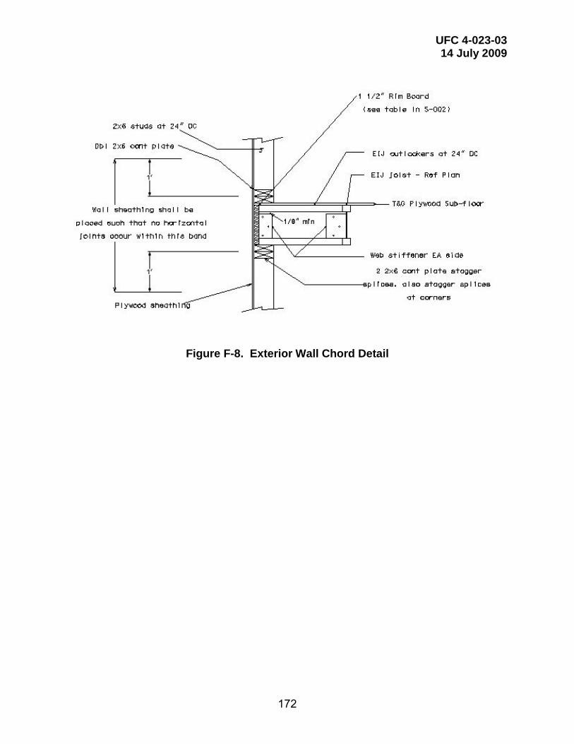
UFC 4-023-03 14 July 2009
172
Figure F-8. Exterior Wall Chord Detail
UFC 4-023-03 14 July 2009
173
APPENDIX G INTERNATIONAL BUILDING CODE MODIFICATIONS FOR CONSTRUCTION OF BUILDINGS TO RESIST PROGRESSIVE COLLAPSE
The following narrative identifies required modifications to the provisions of the International Building Code (IBC) addressing construction documents, structural tests and special inspections for buildings that have been designed to resist progressive collapse. The modifications reference specific sections in the IBC that require modification. Apply IBC requirements except as modified herein. The required IBC modifications are one of two actions, according to the following legend:
LEGEND FOR ACTIONS
[Addition] -- New section added, includes new section number not shown in IBC. [Replacement] -- Delete referenced IBC section and replace it with the narrative shown. Chapter 16 Structural Design 1603 Construction Documents 1603.1.9 [Addition] Progressive Collapse design data. The following information shall be indicated on the construction documents:
1. General note stating the follow:
Design of the building is in accordance with UFC 4-023-03, DD/MM/YYYY. Future additions or alterations to this structure shall not jeopardize the requirements for progressive collapse resistance.
2. Occupancy Category II, III or IV.
3. Method of progressive collapse resistance (Tie Force, Alternate Path, Enhanced Local Resistance or combinations thereof) .
1603.1.10 [Addition] Systems and components requiring special inspections for progressive collapse resistance. Construction documents or specifications shall be prepared for those systems and components requiring special inspection for progressive collapse resistance and shall be submitted for approval as specified in section 1717.1 by the registered design professional responsible for their design and shall be submitted for approval in accordance with section 106.1.

UFC 4-023-03 14 July 2009
174
Chapter 17 Structural Tests and Special Inspections 1701.1 [Replacement] Scope The provisions of this chapter shall govern the quality, workmanship and requirements for materials covered. Materials of construction and tests shall conform to the applicable standards listed in this code.
1716 [Addition] QUALITY ASSURANCE FOR PROGRESSIVE COLLAPSE REQUIREMENTS
1716.1 [Addition] Scope A quality assurance plan shall be provided in accordance with Section 1716.1.1.
1716.1.1 [Addition] When required. A quality assurance plan for progressive collapse requirements shall be provided for the following structures designed for various occupancy categories as follows:
1. Structures designed for Occupancy Category II, where either 1)structural elements provide horizontal and vertical tie force capacity as well as additional ductility requirements in which the shear resistance of the corner and penultimate first story walls and columns is greater than the flexural resistance for lateral loads, or, 2) the alternate path method is used to provide bridging over the deficient elements
2. Structures designed for Occupancy Category III, with horizontal and vertical
tie forces, alternate path design, and enhanced local resistance where the columns or walls in the first two perimeter stories are designed for increased flexural and shear resistance. .
3. Structures designed to Occupancy Category IV, which requires a design
based on the results of a systematic risk assessment of the building. ).
1716.1.2 [Addition] Detailed requirements. When required by Section 1716.1.1, a quality assurance plan shall provide for the following:
1. Horizontal and vertical tie force connections as required based on material type.
2. Roof and floor diaphragm systems including transverse, longitudinal, and peripheral ties..
3. Vertical progressive collapse resisting systems including vertical ties and bridging connections.
4. Perimeter ground floor columns and walls with enhanced ductility requirements to ensure shear capacity is greater than the flexural capacity
1716.2 [Addition] Quality assurance plan preparation. The design of each designated progressive collapse resisting system shall include a quality assurance plan

UFC 4-023-03 14 July 2009
175
prepared by the registered design professional. The quality assurance plan shall identify the following:
1. The designated progressive collapse resisting systems and elements that are subject to quality assurance in accordance with 1716.1.
2. The special inspections and testing to be provided as required by sections 1704 and other applicable sections of this code, including the applicable standards reference by this code.
3. The type and frequency of testing required.
4. The type and frequency of special inspections required.
5. The required frequency and distribution of testing and special inspection reports.
6. The structural observations to be performed.
7. The required frequency and distribution of structural observation reports.
1716.3 [Addition] Contractor responsibility. Each contractor responsible for the construction of the progressive collapse resisting system or progressive collapse component listed in the quality assurance plan shall submit a written contractor’s statement of responsibility to the contracting officer prior to the commencement of work on the system or component. The contractor’s statement of responsibility shall contain the following.
1. Acknowledgement of awareness of the special requirements contained in the quality assurance plan;
2. Acknowledgement that control will be exercised to obtain conformance with the construction documents approved by the building official;
3. Procedures for exercising control within the contractors organization, the method and frequency of reporting the distribution of reports; and
4. Identification and qualification of the person(s) exercising such control and their position(s) in the organization.
1717 [Addition] SPECIAL INSPECTIONS FOR PROGRESSIVE COLLAPSE RESISTANCE
1717.1 [Addition] General. Special inspections for progressive collapse resistance shall follow the requirements of Section 1704.1. Special inspections itemized in Sections 1717.2 through 1717.4 are required for the following:
1. Structures designed for Occupancy Category II, where either 1)s tructural elements provide horizontal and vertical tie force capacity as well as additional ductility requirements in which the shear resistance of the corner

UFC 4-023-03 14 July 2009
176
and penultimate ground floor walls and columns is greater than the flexural resistance for lateral loads, or, 2) the alternate path method is used to provide bridging over the deficient elements
2. Structures designed for Occupancy Category III, with horizontal and vertical
tie forces, alternate path design, and enhanced local resistance where the columns or walls in the first two perimeter stories are designed for increased flexural and shear resistance. .
3. Structures designed to Occupancy Category IV, which requires a design
based on the results of a systematic risk assessment of the building. ).
1717.2 [Addition] Structural steel. Continuous special inspection for structural welding in accordance with AWS D1.1, including floor and roof deck welding.
Exemptions:
1. Single pass fillet welds not exceeding 5/16” (7.9mm) in size.
1717.3 [Addition] Structural Wood. Periodic special inspections during nailing, bolting, anchoring and other fastening of components within the progressive collapse resisting system, including horizontal tie force elements, vertical tie force elements and bridging elements.
1717.4 [Addition] Cold–formed steel framing. Periodic special inspections during welding operations, screw attachment, bolting, anchoring and other fastening of components within the progressive collapse resisting system, including horizontal tie force elements, vertical tie force elements and bridging elements.
1717.5 [Addition] Cast-in-place concrete. Continuous special inspection for reinforcing steel placement with a particular emphasis on reinforcing steel anchorages, laps and other details within the progressive collapse resisting system, including horizontal tie force elements, vertical tie force elements and bridging elements.
1718 STRUCTURAL OBSERVATIONS
1718.1 [Addition] Structural observations. Structural observations shall be provided for the progressive collapse resisting systems as follows:
1. When the contracting officer requires such observation.
2. In structures designed to Occupancy Category IV
The structural engineer of record (SER) should perform the structural observations as defined in Section 1702. In lieu of the SER, a registered design professional with experience in and knowledge of structural engineering principles and practices shall perform the structural observations.