
Progress Status Classified by Issues (Photos and …...Setting water level indicator of underground...
25
Implementation Status Reference (Photos and Figures) Countermeasure [76] Improvement of work evironment Removal of debris, Measurement of radiation dose, Enter into the building (May 9) RPV water gauge proof (May 10) PCV pressure proof (May 11) Setting water level indicator of underground in Reactor Building (May 27) Setting temporary RPV puressure indicator Countermeasure [11] Inject nitrogen gas into the PCV Implementing from April 6 Total inject of nitrogen gas : 45,000m3 (June 15) Progress Status Classified by Issues (Photos and Figures) Issues Unit 1 (1) Cooling the Reactor I. Cooling Countermeasures Syetem outline of nitrogen injection Nitrogen supply apparatus Checking inside of the reactor buildings by Packbot Setting water level indicator Measuring radiation dose inside of reactor building Reference 1
Transcript of Progress Status Classified by Issues (Photos and …...Setting water level indicator of underground...

Implementation Status Reference (Photos and Figures)Countermeasure [76]Improvement of workevironment
Removal of debris, Measurement ofradiation dose, Enter into the building(May 9)RPV water gauge proof (May 10)PCV pressure proof (May 11)Setting water level indicator ofunderground in Reactor Building (May27)Setting temporary RPV puressureindicator
Countermeasure [11]Inject nitrogen gasinto the PCV
Implementing from April 6Total inject of nitrogen gas : 45,000m3(June 15)
Progress Status Classified by Issues (Photos and Figures)Issues
Unit 1
(1) Cooling the R
eactor
I. Cooling
Countermeasures
Syetem outline of nitrogen injection
Nitrogen supply apparatus
Checking inside of thereactor buildings by Packbot
Setting water level indicator
Measuring radiation doseinside of reactor building
Reference
1

Implementation Status Reference (Photos and Figures)Countermeasure [13]Secure heatexchange functionfor the reactor
- Due to the leakage from the primarycontainment vessel, we judged that itis difficult to secure water level of theprimary containment vessel necessaryto enable operation of the pump for thealternative reactor cooling system byincreasing the water injection fromoutside into the reactor pressurevessel.- Therefore, we changed the plan togive priority to the establishment ofcirculating injection cooling for thereactor.- We are studying the possibility ofestablishing circulating cooling withinthe reactor building by usingaccumulated water in the basement ofthe reactor building as the water
・Establishment of cooling tower unit(May 17~)
Progress Status Classified by Issues (Photos and Figures)Issues
I. Cooling
(1) Cooling the R
eactors
Unit 1
Countermeasures
Inside reactor building of Unit 1in front of the truck bay door
Demolished and removed debrisat the truck bay door, whichwould be obstacle for installationof alternative cooling system(from May 10 to May 15)
[Under consideration] Outline of circulatingcooling system within the reactor building
Cooling tower unitPlate-type heat exchanger
PCV
Reactor Building
SubmergedPumpBasement
Cooling TowerUnit
June 3, Completion of build-up of cooling uniton the trailer
Heat Exchanger
2
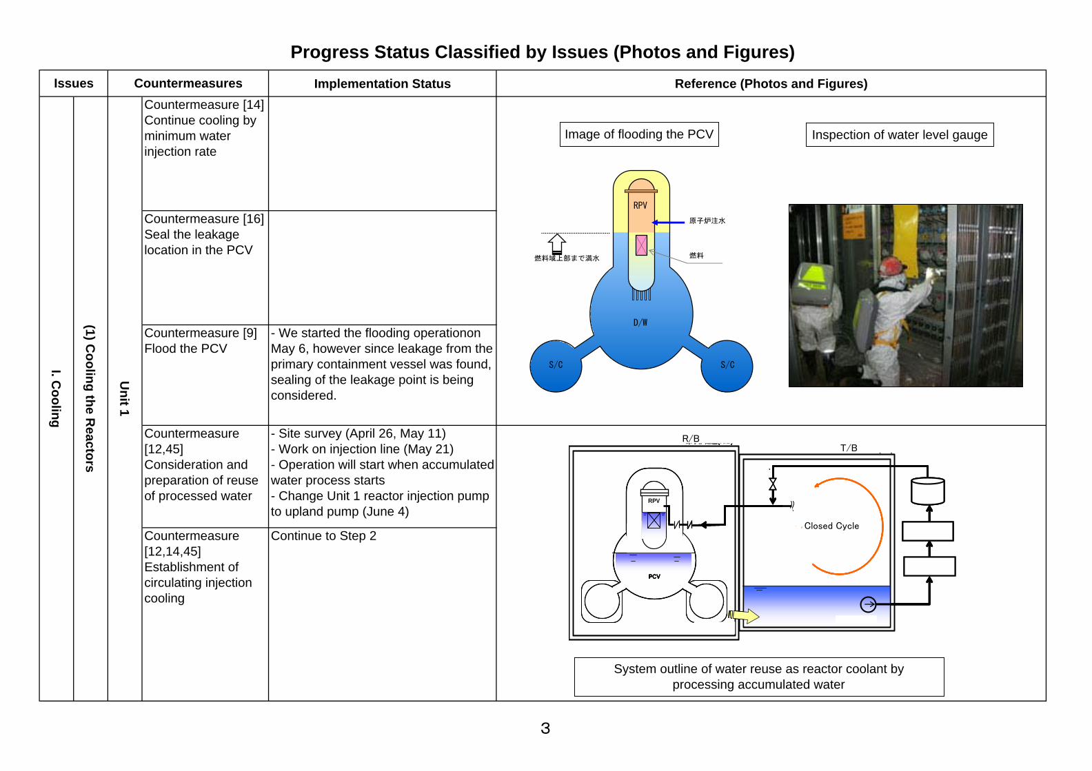
Implementation Status Reference (Photos and Figures)Countermeasure [14]Continue cooling byminimum waterinjection rate
Countermeasure [16]Seal the leakagelocation in the PCV
Countermeasure [9]Flood the PCV
- We started the flooding operationonMay 6, however since leakage from theprimary containment vessel was found,sealing of the leakage point is beingconsidered.
Countermeasure[12,45]Consideration andpreparation of reuseof processed water
- Site survey (April 26, May 11)- Work on injection line (May 21)- Operation will start when accumulatedwater process starts- Change Unit 1 reactor injection pumpto upland pump (June 4)
Countermeasure[12,14,45]Establishment ofcirculating injectioncooling
Continue to Step 2
Progress Status Classified by Issues (Photos and Figures)Issues
I. Cooling
(1) Cooling the R
eactors
Unit 1
Countermeasures
燃料域上部まで満水
原子炉注水
RPV
D/W
S/C S/C
燃料
Image of flooding the PCV Inspection of water level gauge
クローズドサイクル
タービン建屋(T/B)
給水系に接続
原子炉建屋(R/B)
PCV
T/Bに流入
RPV
淡水注入
ポンプ
タンク
淡水化設備
汚染水処理設備
クローズドサイクル
タービン建屋(T/B)
給水系に接続
原子炉建屋(R/B)
PCV
T/Bに流入
RPV
淡水注入
ポンプ
タンク
淡水化設備クローズドサイクルクローズドサイクル
タービン建屋(T/B)
給水系に接続
原子炉建屋(R/B)
PCV
T/Bに流入
RPV
淡水注入
ポンプ
タンク
淡水化設備
汚染水処理設備
System outline of water reuse as reactor coolant byprocessing accumulated water
Closed Cycle
T/BR/B
3

Implementation Status Reference (Photos and Figures)Countermeasure [76]Improvement of workenvironment
Measurement of radiation dose,Preparation to enter into the building
Countermeasure [11]Inject nitrogen gasinto the PCV
Installed piping to the entrance of thebuilding (May 7)
Countermeasure [13]Secure heatexchange function forthe reactor
- Planning site survey for detail designafter improvement of work environment
Countermeasure [6]Consideration ofsealing the leakagelocation in the PCV
- Testing the sealing measure at laboratory
<next step>- based on the result of test at laboratory, move on to countermeasure [16]
Countermeasure [16]Seal the leakagelocation in the PCV
- Start construction after confirming thefeasibility of sealing method
Countermeasure [9]Flood the PCV
Countermeasure [14]Fuel cooling byminimum waterinjection rate
- Continue injecting water within the limitof storage capacity of leaked water
Countermeasure[12,45]Consideration andpreparation ofreusing processedwater
- Implementing injection line work(ongoing from April 9)- Switch Unit 2 reactor injection pump toupland pump (May 30)- Inservice with the launch ofaccumulated water treatment
Countermeasure[12,14,45]Establishment ofcirculating injectioncooling
Continue to Step 2
Progress Status Classified by Issues (Photos and Figures)Issues
I. Cooling
(1) Cooling the reactors
Unit 2
Countermeasures
Fill grout material
waterinjection
wateroutflow
ventilation
T/B
R/B
Image of countermeasure to seal thedamaged location in the PCV
Open a hole in the floor of 1st floorof R/B and fill grout in the torus
4

Implementation Status Reference (Photos and Figures)Countermeasure [76]Improvement of workenvironment
- Removal of debris, Measurement ofradiation dose, Preparation to enter intothe building
Countermeasure [11]Inject nitrogen gas intothe PCV
- Installed piping to the entrance of thebuilding (May 11)
Countermeasure [13]Secure heat exchangefunction for the reactor
- Site survey for detail design will startafter the improvement of workenvironment
Increase waterinjection
- Will confirm the leakagestatus/temperature etc and choosecountermeasure [16] or [14]
Countermeasure [16]Seal the leakagelocation in the PCV
Countermeasure [9]Flood the PCV
Countermeasure [14]Fuel cooling byminimum waterinjection rate
Countermeasure[12,45]Considenration andpreparation for reuseof processed water
- Implementing injection line work(ongoing from April 16)- Change Unit 3 reactor injection pump toupland pump (May 27)- In service with the launch ofaccumulated water treatment
Countermeasure[12,14,45]Establishment ofcirculating injectioncooling
Continue to Step 2
Progress Status Classified by Issues (Photos and Figures)Issues
I. Cooling
(1) Cooling the reactors
Unit 3
CountermeasuresDemolished and removed debris at the truck-bay door, which would be obstacle for installationof alternative facility
(After removal May 25)
Truck-bay door /Broken pillars
Truck-bay door / Inside
Machine hatch spaceon the 1st floor of reactor building
Status of debris demolition and removal work
Removal of outside pillars by aradio controlled backhoe
Removal of debris by "Brokk"(wired remote control)
Packing into containerby a shielded forklift
(After removal May 30) (After removal June 4)
5

Implementation status Reference (Photos and Figures)
Countermeasure [24]Restoration of normalcooling system
- Radiation measurement by γcameraand robot (from April 30 to May 6)- Radiation reduction by flushing andshielding facility (from May 11 to May15)- Water injection through normalcooling system (May 29)
Countermeasure[25,27]Install heatexchanger
- Manufacturing heat exchanger- Circulating water cooling operation(End of June)
Countermeasure [22]Continuation of waterinjection by "Giraffe",etc
- Standby as backup after restoration tonormal water injection line- Reliability improvement: enhanceddurability of hoses- Measures to reduce radiation dose:switch to remote-controlled operation (arm, water injection operation)
Progress Status Classified by Issues (Photos and Figures)Issues
I. Cooling
(2) Spent Fuel Pool
Unit 1
Countermeasures
Image of remote control operation of concrete pumping vehicle
lighting
reactorbuilding
wireless LAN
3 cameras for monitoringoverall situation
(installed per unit)
control box 7 cameras to monitorgauges in the vehicle
control box
slope
armcamera
shield
radio connectingstation control devices from
telecommunication room
image/view
main anti earthquakebuilding
observatory
able to control fromobservatory using mobilestation vehicle
internal network
connecting box(installed per
unit)
optical fiber
wireless LANantenna
Overview of SFP cooling function
Cooling tower
Plate-type heat exchanger
R/B
FPC Hx
FPC
6

Implementation status Reference (Photos and Figures)Countermeasure [23]Restoration of waterinjection throughnormal cooling system
- continuing
Countermeasure[23,27]Install heatexchanger
- Installed heat exchanger andoperating circulating cooling system(from May 31)- Temperature of spent fuel pool:approximately 31 ℃ (as of June 6)
Countermeasure [22]Continuation of waterinjection by "Giraffe"etc
- Standby as backup after restoration tonormal water injection line- Reliability improvement: enhanceddurability of hoses- Measures to reduce radiation dose:switch to remote-controlled operation (arm, water injection operation)
Countermeasure [24]restoration of normalcooling system
- Confirmation of system integritythrough water level measurement by"Giraffe," etc. (from May 8 to May 15)- Water injection through normalcooling system (ongoing from May 16)
Countermeasure[25,27]Install heatexchanger
- Manufacturing heat exchanger.Installation work will start aftertransferred to the site. (from June 10)- Circulating water cooling operation(End of June)
Unit 3
(2) Spent Fuel Pool
I. Cooling
Progress Status Classified by Issues (Photos and Figures)Issues
Unit 2
Countermeasures
Unit 2 Heat Exchanger Unit
Unit 3 Spent Fuel Pool
7
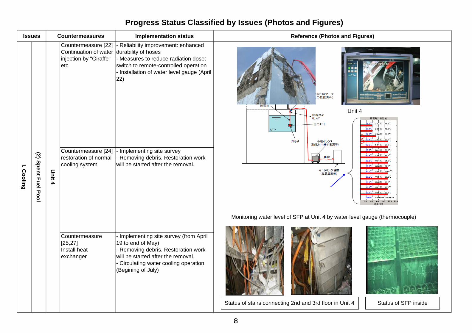
Implementation status Reference (Photos and Figures)Countermeasure [22]Continuation of waterinjection by "Giraffe"etc
- Reliability improvement: enhanceddurability of hoses- Measures to reduce radiation dose:switch to remote-controlled operation- Installation of water level gauge (April22)
Countermeasure [24]restoration of normalcooling system
- Implementing site survey- Removing debris. Restoration workwill be started after the removal.
Countermeasure[25,27]Install heatexchanger
- Implementing site survey (from April19 to end of May)- Removing debris. Restoration workwill be started after the removal.- Circulating water cooling operation(Begining of July)
Progress Status Classified by Issues (Photos and Figures)Issues
I. Cooling
(2) Spent Fuel Pool
Unit 4
Countermeasures
Status of stairs connecting 2nd and 3rd floor in Unit 4 Status of SFP inside
Water injection by "Giraffe" at Unit 4
Monitoring water level of SFP at Unit 4 by water level gauge (thermocouple)
8

Implementation status Reference (Photos and Figures)Countermeasure [37, 39,42] Securing sufficientplaces to storecontaminated water
- Transferring to Centralized Waste TreatmentFacility (Process Main Building and High-temperatureIncineration Building) after checking water leakingstopped
o Process Main Building: After checking water leaking stopped etc.,transferred accumulated water from Unit 2 TurbineBuilding. (April 19)
o High-temperature Incineration Building: After checking water leaking stopped etc.,transferred accumulated water from Unit 3 TurbineBuilding. (May 17)
- Installation of tankso For receiving treated water approx. 11,000t (May 10) approx. 2,000t (May 20)
<Implementation hereafter>o For receiving treated water brought in and installed underground tanks approx.20,000t (from June 4)o For receiving treated water will bring in and install underground tanks approx.10,000t (after mid June)
Countermeasure [64]Mitigation of contaminationin the ocean
- Setting up silt fence- Preparation work for setting up steel pipe sheet pile [removal of curtain wall] (from June 2)- Purification of sea water by circulating purificationsystem (from June 13)- Installation of sliding concrete plate (from June 12)
<Implementation hereafter>- Planning for setting up steel pipe sheet pile
Countermeasure [65]Containment of high-levelradioactive water
- closure of sea water pipe vertical shaft Unit 2: completed on June 2, Unit 3: completed on May 26, Unit 4: completed on April 6- closure of pits and others Unit 1: completed on May 17 (planned) Unit 2: completed on June 9 Unit 3: completed on June 10 Unit 4: completed on June 10
Progress Status Classified by Issues (Photos and Figures)Issues
II. Mitigation
(3) Accum
ulated Water
High level
Countermeasures
<Transferring into Centralized Waste Treatment Facility>
Tanks to receive treated water Underground tanks for treated water (image)
Setting up silt fence
Closure of sew water pipe vertical shaft(left: before closure, right: after closure)
Closure of pit(left: before closure, right: after closure)
T/B at Unit 3 T/B at Unit 4T/B at Unit 1 T/B at Unit 2
R/B atUnit 1
R/B atUnit 2
R/B atUnit 3
R/B atUnit 4
Vertical Shaftat Unit 2
Process MainBuilding
Hatch at Unit 3 Centralized WasteTreatment Facility
High-temperatureIncinerationBuilding
9
Progress Status Classified by Issues (Photos and Figures)
Implementation status Reference (Photos and Figures)
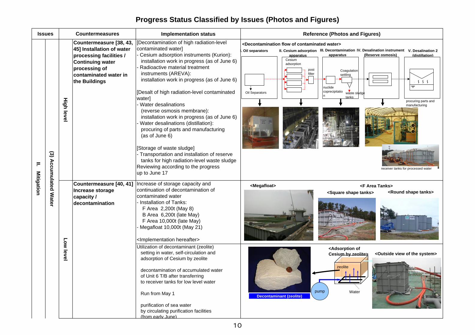
Countermeasure [40, 41]Increase storagecapacity /decontamination
Increase of storage capacity andcontinuation of decontamination ofcontaminated water- Installation of Tanks: F Area 2,200t (May 8) B Area 6,200t (late May) F Area 10,000t (late May)- Megafloat 10,000t (May 21)
<Implementation hereafter> Utilization of decontaminant (zeolite)
setting in water, self-circulation and adsorption of Cesium by zeolite
decontamination of accumulated water of Unit 6 T/B after transferring to receiver tanks for low level water
Run from May 1
purification of sea water by circulating purification facilities
(from early June)
[Decontamination of high radiation-levelcontaminated water]- Cesium adsorption instruments (Kurion): installation work in progress (as of June 6)- Radioactive material treatment instruments (AREVA): installation work in progress (as of June 6)
[Desalt of high radiation-level contaminatedwater]- Water desalinations (reverse osmosis membrane): installation work in progress (as of June 6)- Water desalinations (distillation): procuring of parts and manufacturing (as of June 6)
[Storage of waste sludge]- Transportation and installation of reserve tanks for high radiation-level waste sludgeReviewing according to the progressup to June 17
Countermeasure [38, 43,45] Installation of waterprocessing facilities /Continuing waterprocessing ofcontaminated water inthe Buildings
High level
(3) Accum
ulated Water
Issues
Low level
II. Mitigation
Countermeasures
procuring parts andmanufacturing
I. Oil separators
Oil Separatorsnuclidecoprecipitation
Coagulationsettling
waste sludgetanks
IV. Desalination instrument(Reserve osmosis)
V. Desalination 2(distillation)
~~~~
II. Cesium adsorptionapparatus
Cesiumadsorption
postfilter
<Decontamination flow of contaminated water>
<Megafloat>
Decontaminant (zeolite)
<F Area Tanks><Square shape tanks> <Round shape tanks>
<Adsorption ofCesium by zeolite> <Outside view of the system>
III. Decontaminationapparatus
zeolite
pump Water
receiver tanks for processed water
10
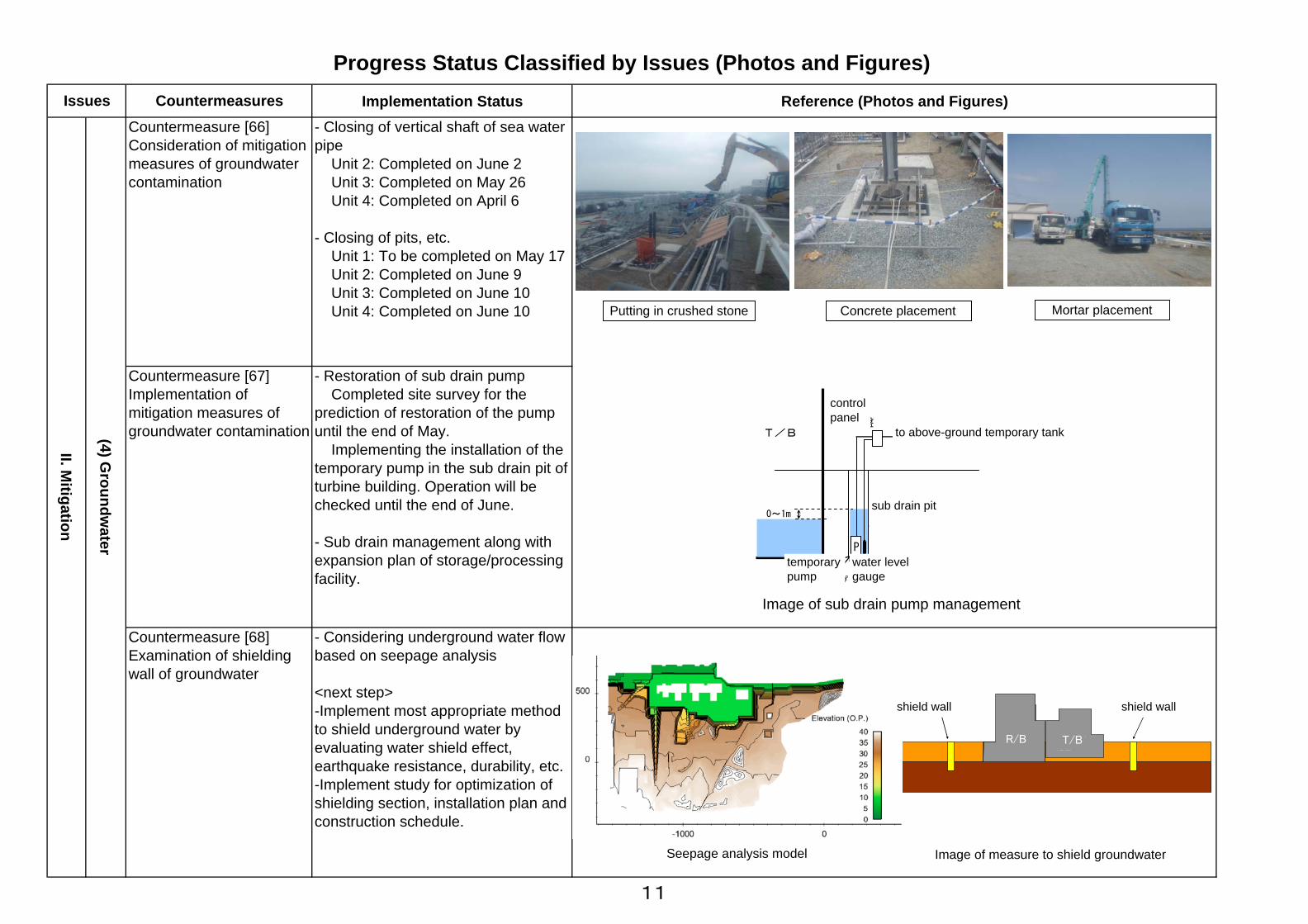
Implementation Status Reference (Photos and Figures)- Closing of vertical shaft of sea waterpipe Unit 2: Completed on June 2 Unit 3: Completed on May 26 Unit 4: Completed on April 6
- Closing of pits, etc. Unit 1: To be completed on May 17 Unit 2: Completed on June 9 Unit 3: Completed on June 10 Unit 4: Completed on June 10
- Considering underground water flowbased on seepage analysis <next step>-Implement most appropriate methodto shield underground water byevaluating water shield effect,earthquake resistance, durability, etc.-Implement study for optimization ofshielding section, installation plan andconstruction schedule.
Countermeasure [66]Consideration of mitigationmeasures of groundwatercontamination
II. Mitigation
Progress Status Classified by Issues (Photos and Figures)Issues Countermeasures
(4) Groundw
ater
Countermeasure [68]Examination of shieldingwall of groundwater
Countermeasure [67]Implementation ofmitigation measures ofgroundwater contamination
- Restoration of sub drain pump Completed site survey for theprediction of restoration of the pumpuntil the end of May. Implementing the installation of thetemporary pump in the sub drain pit ofturbine building. Operation will bechecked until the end of June.
- Sub drain management along withexpansion plan of storage/processingfacility.
Putting in crushed stone Concrete placement Mortar placement
Seepage analysis model Image of measure to shield groundwater
P
仮設ポンプ
0~1m
T/B 地上仮設タンクへ
水位計
制御盤
サブドレンピット
Image of sub drain pump management
遮水壁 遮水壁
原子炉建屋
タービン建屋
shield wall shield wall
temporarypump
water levelgauge
sub drain pit
to above-ground temporary tank
controlpanel
R/B T/B
11
Implementation Status Reference (Photos and Figures)
(5) Atmosphere / Soil
Progress Status Classified by Issues (Photos and Figures)Issues Countermeasures
Countermeasure [52]Dispersion of inhibitors
II. Mitigation
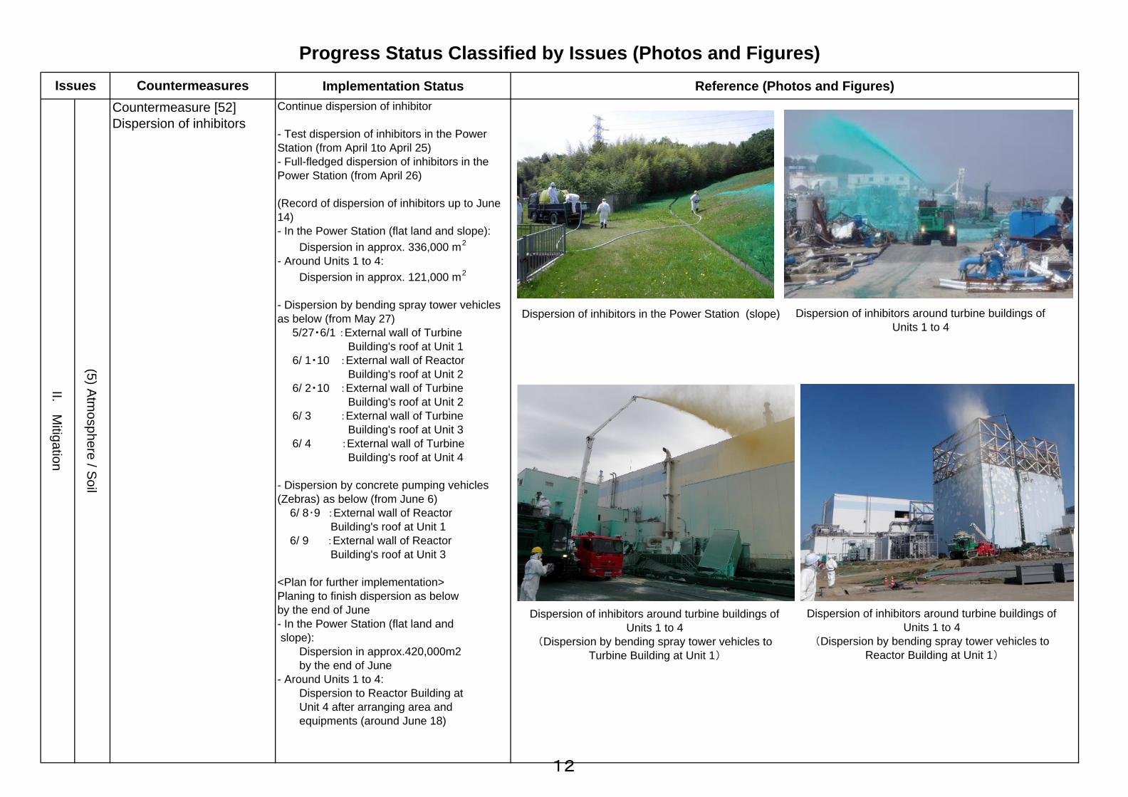
Continue dispersion of inhibitor
- Test dispersion of inhibitors in the PowerStation (from April 1to April 25)- Full-fledged dispersion of inhibitors in thePower Station (from April 26)
(Record of dispersion of inhibitors up to June14)- In the Power Station (flat land and slope): Dispersion in approx. 336,000 m2
- Around Units 1 to 4: Dispersion in approx. 121,000 m2
- Dispersion by bending spray tower vehiclesas below (from May 27) 5/27・6/1 :External wall of Turbine Building's roof at Unit 1 6/ 1・10 :External wall of Reactor Building's roof at Unit 2 6/ 2・10 :External wall of Turbine Building's roof at Unit 2 6/ 3 :External wall of Turbine Building's roof at Unit 3 6/ 4 :External wall of Turbine Building's roof at Unit 4
- Dispersion by concrete pumping vehicles(Zebras) as below (from June 6) 6/ 8・9 :External wall of Reactor Building's roof at Unit 1 6/ 9 :External wall of Reactor Building's roof at Unit 3
<Plan for further implementation>Planing to finish dispersion as belowby the end of June- In the Power Station (flat land and slope): Dispersion in approx.420,000m2 by the end of June- Around Units 1 to 4: Dispersion to Reactor Building at Unit 4 after arranging area and equipments (around June 18)
Dispersion of inhibitors around turbine buildings ofUnits 1 to 4
Dispersion of inhibitors around turbine buildings ofUnits 1 to 4
(Dispersion by bending spray tower vehicles toTurbine Building at Unit 1)
Dispersion of inhibitors around turbine buildings ofUnits 1 to 4
(Dispersion by bending spray tower vehicles toReactor Building at Unit 1)
Dispersion of inhibitors in the Power Station (slope)
12
Implementation Status Reference (Photos and Figures)
Progress Status Classified by Issues (Photos and Figures)Issues Countermeasures
(5) Atm
osphere / Soil
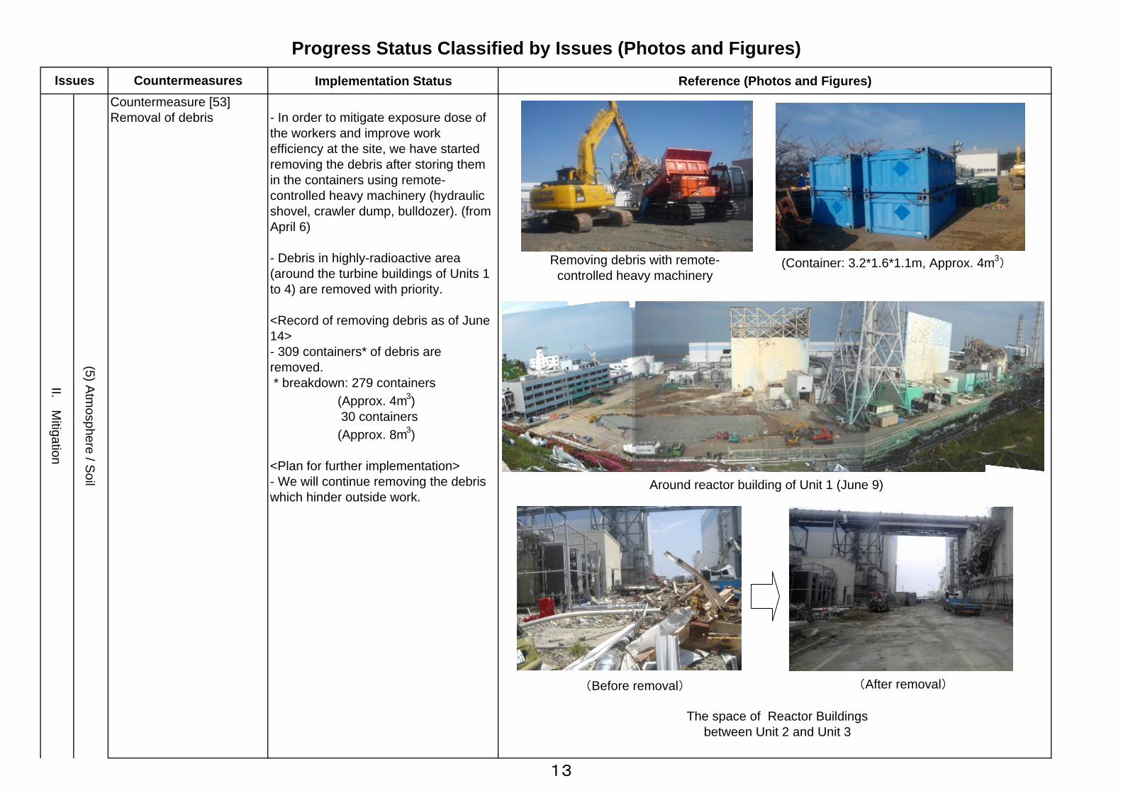
Countermeasure [53]Removal of debris - In order to mitigate exposure dose of
the workers and improve workefficiency at the site, we have startedremoving the debris after storing themin the containers using remote-controlled heavy machinery (hydraulicshovel, crawler dump, bulldozer). (fromApril 6)
- Debris in highly-radioactive area(around the turbine buildings of Units 1to 4) are removed with priority.
<Record of removing debris as of June14>- 309 containers* of debris areremoved. * breakdown: 279 containers (Approx. 4m3) 30 containers (Approx. 8m3)
<Plan for further implementation>- We will continue removing the debriswhich hinder outside work.
II. Mitigation
Removing debris with remote-controlled heavy machinery
(Container: 3.2*1.6*1.1m, Approx. 4m3)
(Before removal) (After removal)
Around reactor building of Unit 1 (June 9)
The space of Reactor Buildingsbetween Unit 2 and Unit 3
13
Implementation Status Reference (Photos and Figures)
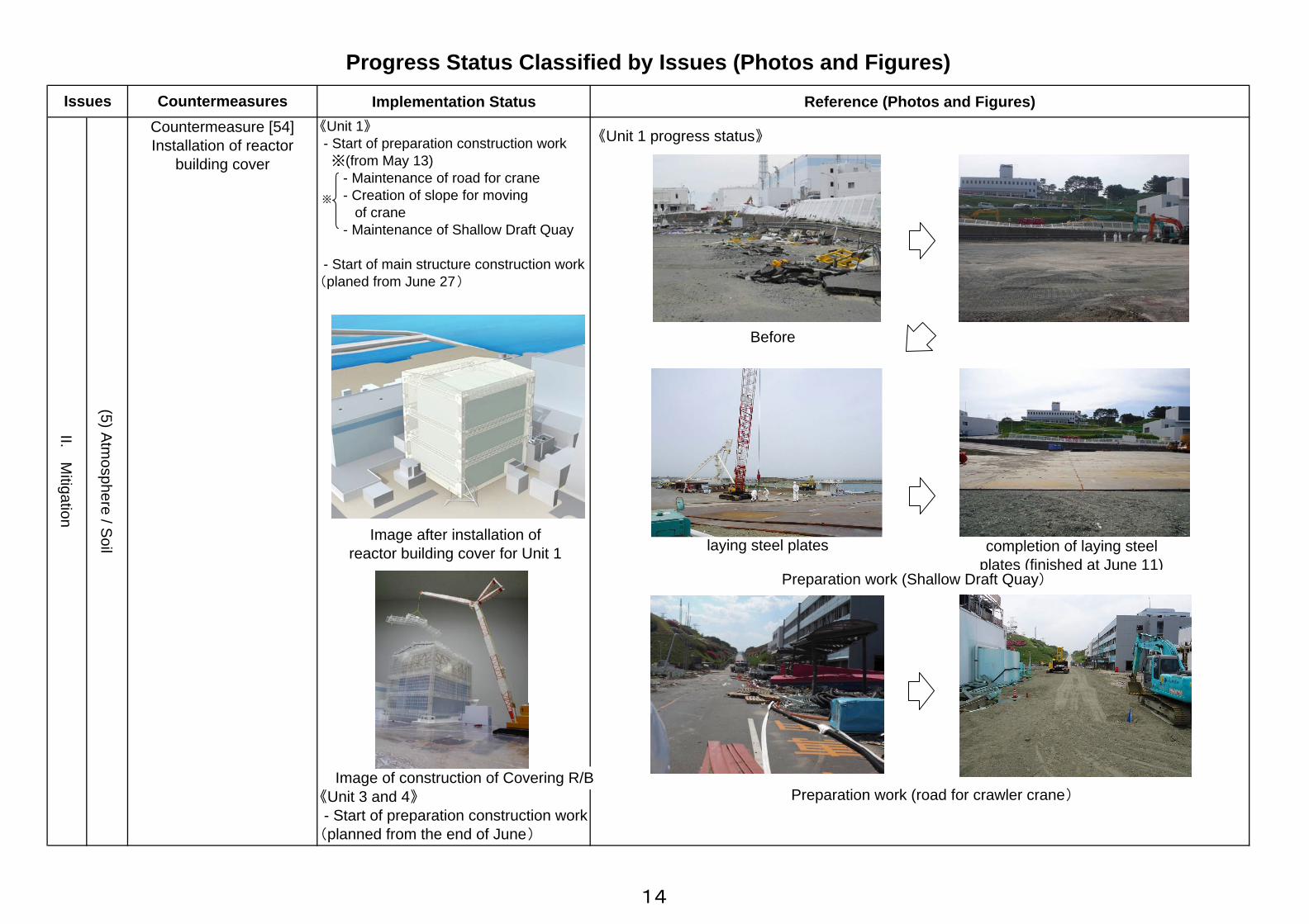
《Unit 3 and 4》 - Start of preparation construction work(planned from the end of June)
Progress Status Classified by Issues (Photos and Figures)Issues Countermeasures
《Unit 1》 - Start of preparation construction work ※(from May 13) - Maintenance of road for crane - Creation of slope for moving of crane - Maintenance of Shallow Draft Quay
- Start of main structure construction work(planed from June 27)
II. Mitigation
(5) Atmosphere / Soil
Countermeasure [54]Installation of reactor
building cover
Image after installation ofreactor building cover for Unit 1
※
Preparation work (Shallow Draft Quay)
Before砕石投入・敷均し
completion of laying steelplates (finished at June 11)
laying steel plates
Preparation work (road for crawler crane)
《Unit 1 progress status》
Image of construction of Covering R/B
14

Countermeasures Implementation status Reference (Photos and Figures)
Continue monitoring in and out of the power station
[Land Area]<Monitoring within 20 km radius of the periphery>- Monitoring of airborne radiation dose rate at 50 points by Utility Support Team (once/week)- Land sampling at 50 points and additional points (approx. 50 points) by Utility Support Team (June 10 and 13, once/two months)- Monitoring at 5 points between 3km to 5 km radius of the periphery at the timing of opening air-lock doors of Unit 2 Reactor Building (June 19 and 20)
<Monitoring within the Site>- Monitoring of airborne radiation dose rate around West Gate ot the SIte (everyday)- Monitoring of radiation dose rate at the uppper part of Reactor Building with water pumper trucks etc. (once/month) Unit 1 (May 22), Unit 4 (May 23), Unit 2 (after June 24), Unit 3 (June 13)- Monitoring of radiation dose rate around switching stations on the west side of Reactor Building (everyday) Unit 1 and 2 (since July), Unit 3 and 4 (since July)- Metigation measures on backgrouds of monitoring posts (mitigation from the impcatof land) MP8(May 20), MP3(May 23), MP2(since July)
Progress Status Classified by Issues (Photos and Figures)Issues
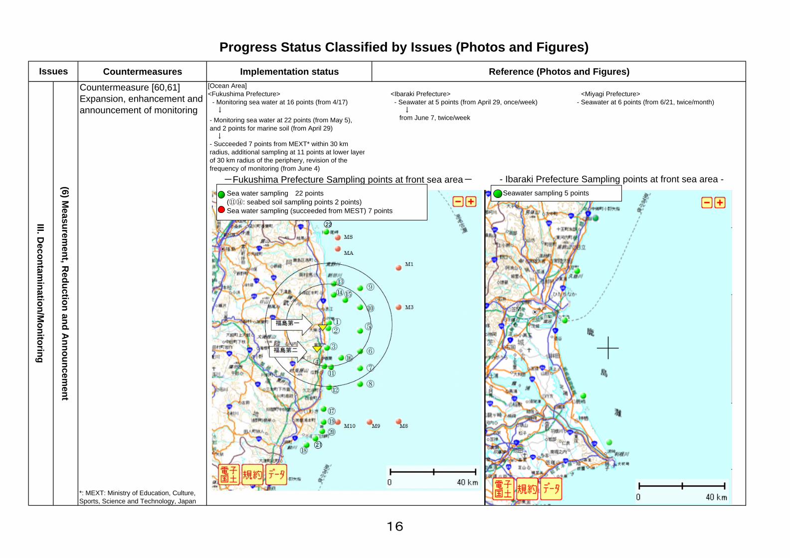
Countermeasure [60,61]Expansion, enhancement andannouncment of monitoring
III. Decontam
ination/ Monitoring
(6) Measurem
ent, Reduction and A
nnouncement
Land Sampling by Utility Support Team (20 km radius of the periphery)
Measurement Result of Airborne Radiation Dose Rate of 20 kimRadius of the Periphery (date: June 3, 2011)
Upper: Point No.Lower: Airborneradiation dose (μSv/h)
福島第一 空気中の放射性物質濃度の推移
0.0000001
0.000001
0.00001
0.0001
0.001
0.01
0.1
3/19
3/22
3/25
3/28
3/31
4/3
4/6
4/9
4/12
4/15
4/18
4/21
4/24
4/27
4/30
5/3
5/6
5/9
5/12
5/15
5/18
5/21
5/24
5/27
5/30
6/2
6/5
6/8
Bq/cm3
I-131 Cs-134 Cs-137
Airborne Radiation Dose Limit outside of Surrounding Monitoring Area(Bq/cm3) I-131: 5E-06 Cs-134: 2E-05 Cs-
Trend of Airborne Radiation Dose Rate at Fukushima Daiichi
15
Countermeasures Implementation status Reference (Photos and Figures)Countermeasure [60,61]Expansion, enhancement andannouncement of monitoring
<Ibaraki Prefecture> <Miyagi Prefecture> - Seawater at 5 points (from April 29, once/week) - Seawater at 6 points (from 6/21, twice/month) ↓ from June 7, twice/week
*: MEXT: Ministry of Education, Culture,Sports, Science and Technology, Japan
Progress Status Classified by Issues (Photos and Figures)
(6) Measurem
ent, Reduction and A
nnouncement
III. Decontam
ination/Monitoring
Issues[Ocean Area]<Fukushima Prefecture> - Monitoring sea water at 16 points (from 4/17) ↓
- Ibaraki Prefecture Sampling points at front sea area --Fukushima Prefecture Sampling points at front sea area- Seawater sampling 5 points
- Monitoring sea water at 22 points (from May 5),and 2 points for marine soil (from April 29) ↓- Succeeded 7 points from MEXT* within 30 kmradius, additional sampling at 11 points at lower layerof 30 km radius of the periphery, revision of thefrequency of monitoring (from June 4)
Sea water sampling 22 points (⑪⑭: seabed soil sampling points 2 points) Sea water sampling (succeeded from MEST) 7 points
16
Implementation status Reference (Photos and Figures)
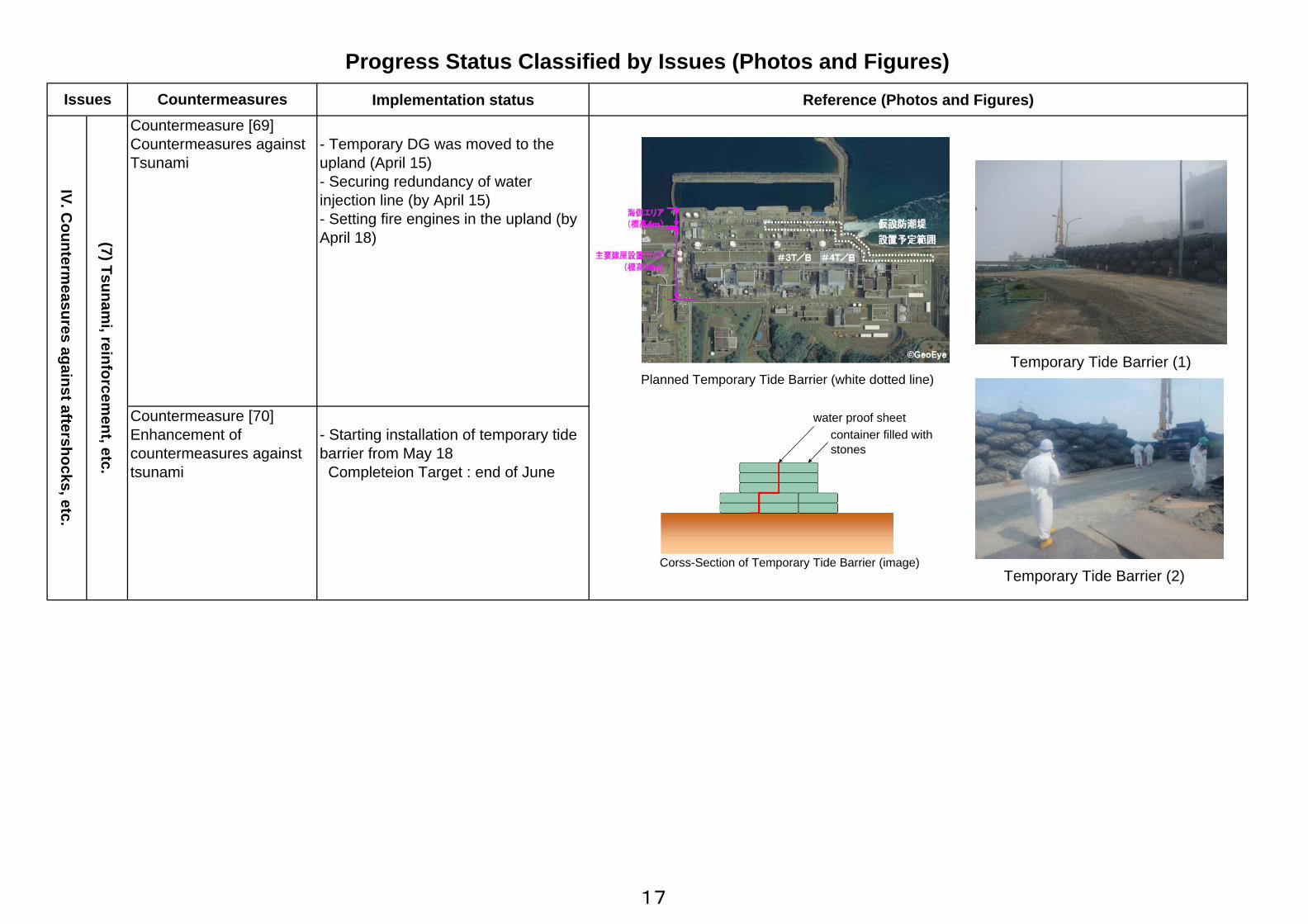
- Temporary DG was moved to theupland (April 15)- Securing redundancy of waterinjection line (by April 15)- Setting fire engines in the upland (byApril 18)
- Starting installation of temporary tidebarrier from May 18 Completeion Target : end of June
Progress Status Classified by Issues (Photos and Figures)Issues
IV. Counterm
easures against aftershocks, etc.
(7) Tsunami, reinforcem
ent, etc.
CountermeasuresCountermeasure [69]Countermeasures againstTsunami
Countermeasure [70]Enhancement ofcountermeasures againsttsunami
Planned Temporary Tide Barrier (white dotted line)
Temporary Tide Barrier (2)
Temporary Tide Barrier (1)
water proof sheetcontainer filled withstones
Corss-Section of Temporary Tide Barrier (image)
17

Implementation Status Reference (Photos and Figures)Countermeasure [26]Installation ofsupporting structureunder the bottom ofspent fuel pool
- Soundness of structure was analyzedand evaluated
- Secure the route to the area to installsupporting structure (removing debris・establish a footholdat hatch・removing shield block)・Removing obstacle at the area・installshielding・Steel pillar installation is progressing(as of June 15)
<Next Step>・Steel pillar installation・Pour concrete and grout(~until theend of July)
IV. Counterm
easures against aftershocks, etc
(7) Tsunami, R
einforcement, etc.
Progress Status Classified by Issues (Photos and Figures)Issues
Unit4
Countermeasures
Steel pillar installation Concrete wall
Removing debris at truck-bay door
Establish a foothold at hatch
Removing obstacle・install shieldingBefore the work Steel pillar installation(as of June 15)
Securing route
Installation of supporting structureunder the bottom of spent fuel pool
Outline of supportingstructure installation
Removing debris
18
Implementation Status Reference (Photos and Figures)
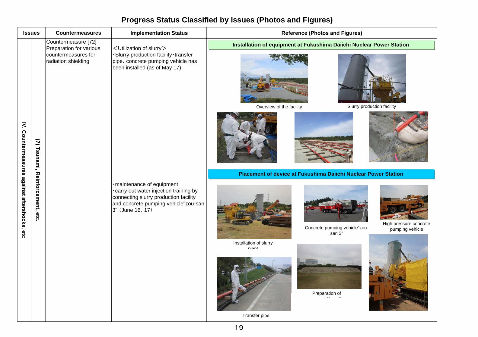
・maintenance of equipment・carry out water injection training byconnecting slurry production facilityand concrete pumping vehicle"zou-san3" (June 16,17)
(7) Tsunami, R
einforcement, etc.
Progress Status Classified by Issues (Photos and Figures)Issues
IV. Counterm
easures against aftershocks, etc
<Utilization of slurry>・Slurry production facility・transferpipe、concrete pumping vehicle hasbeen installed (as of May 17)
CountermeasuresCountermeasure [72]Preparation for variouscountermeasures forradiation shielding
Installation of equipment at Fukushima Daiichi Nuclear Power Station
Transfer pipe
Slurry production facilityOverview of the facility
Installation of slurryplant
Preparation oft i l( d)
Concrete pumping vehicle"zou-san 3"
Placement of device at Fukushima Daiichi Nuclear Power Station
High pressure concretepumping vehicle
19

Implementation status Reference (Photos and Figures)- Improvement of meals, upgrade oflodging facility- Securing daily life water
- Expansion of temporary dormitory- Increasing available amount of dailylife water
(8) Life/work environm
ent
[Countermeasure 75]Continuing andenhancement ofimprovement o workers'life/work environment
Progress Status Classified by Issues (Photos and Figures)Issues Countermeasures
[Countermeasure 74]Improvement of workers'like/work environment
V. Environment Im
provement
Fukushima Daini Gym
Drinking water
Bunk bed(whole) Shower room
Bunk bed
20

Implementation Status Reference (Photos and Figures)
- Installation of rest stations at the site- Expansion of rest stations at the siteand restoration of original rest stations
(8) Life/work environm
ent
Progress Status Classified by Issues (Photos and Figures)Issues Countermeasure
[Countermeasure 74]Improvement workers'life/work environment[Countermeasure 75]Continuing andenhancement ofimprovement of workers'life/work environment
V. Environment Im
provement
Rest station in front of Main Anti-Earthquake Building
Rest stations in front of MainAnti-Earthquake Building
Rest station for a cooperative firm (Toshiba)
Appearance of the rest station Inside the rest station
Drinking waterFoot-wash stationDrinking waterInside the rest station (1)
Inside the rest station (2)
Status of Installation of restt ti
date Place Width Capacity Spec Remark
Rest stations installation status at Fukushima Daiichi
Layout of rest stations at Fukushima Daiichi
Rest stations installation status
In-serviceUnder construction
21

Implementation Status Reference (Photos and Figures)- Improvement of protective equipmentProtective equipment according towork environment is provided in orderto secure safety during radiation work.
Progress Status Classified by Issues (Photos and Figures)Issues Countermeasure
[Countermeasure 77]Improvement of radiationcontrol[Countermeasure 78]Continuing improvementof radiation control
(9) Radiation control / M
edical care
V. Environment Im
provement
Special protective gear:Protective suit which can beexpected to shield beta rayand low-energy gamma ray
Closed-circuit oxygen breathing apparatus:It can realize a long 120-minute usage, circulatingaspirated air with oxygen inside the cylinder.It's suitable for usage in oxygen-less hazardousarea.
Half-faced mask:In case that radioactivitydensity is low and stable,workers put half-face masks,not full-face, on (withgoggles), which enables tolighten the workload ofworkers.
Respiratory protective device with electric fan:The mask can blow in cleaned air which is filteredusing electric fan. Internal pressure is kept higherthan environmental pressure in order to reduce therisk of inhaling particulate. Also, it realizes tobreathe freely and lighten loss of bodily strength.
Under consideration forintroduction
22
Implementation status Reference (Photos and Figures)
(9)Radiation control/m
edical care
Progress Status Classified by Issues (Photos and Figures)Issues Countermeasures
[Countermeasure 77]Improvement of radiationcontrol[Countermeasure 78]Continuing improvementof radiation control
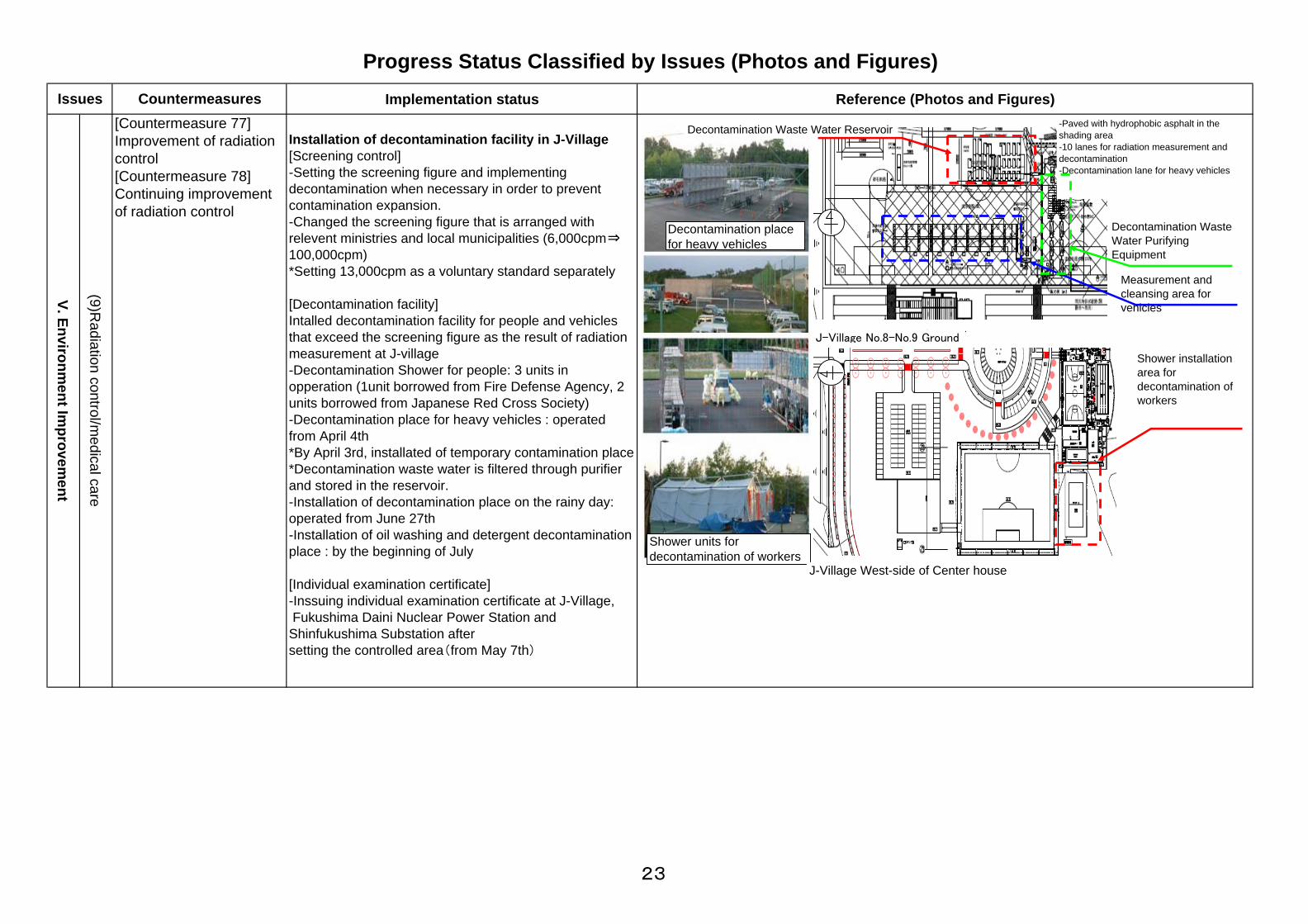
Installation of decontamination facility in J-Village[Screening control]-Setting the screening figure and implementingdecontamination when necessary in order to preventcontamination expansion.-Changed the screening figure that is arranged withrelevent ministries and local municipalities (6,000cpm⇒100,000cpm)*Setting 13,000cpm as a voluntary standard separately
[Decontamination facility]Intalled decontamination facility for people and vehiclesthat exceed the screening figure as the result of radiationmeasurement at J-village-Decontamination Shower for people: 3 units inopperation (1unit borrowed from Fire Defense Agency, 2units borrowed from Japanese Red Cross Society)-Decontamination place for heavy vehicles : operatedfrom April 4th*By April 3rd, installated of temporary contamination place*Decontamination waste water is filtered through purifierand stored in the reservoir.-Installation of decontamination place on the rainy day:operated from June 27th-Installation of oil washing and detergent decontaminationplace : by the beginning of July
[Individual examination certificate]-Inssuing individual examination certificate at J-Village, Fukushima Daini Nuclear Power Station andShinfukushima Substation aftersetting the controlled area(from May 7th)
V. Environment Im
provement
Shower installationarea fordecontamination ofworkers
-Paved with hydrophobic asphalt in theshading area-10 lanes for radiation measurement anddecontamination-Decontamination lane for heavy vehicles
Measurement andcleansing area forvehicles
Decontamination WasteWater PurifyingEquipment
Decontamination Waste Water Reservoir
JヴィレッジNo8~No9グラウンド
Jヴィレッジセンターハウス西側
Decontamination placefor heavy vehicles
Shower units fordecontamination of workers
J-Village No.8-No.9 Ground
J-Village West-side of Center house
23

Implementation Status References (Photos and Figures)
Progress Status Classified by Issues (Photos and Figures)
Issues CountermeasuresCountermeasure [77]Enhancement of radiationcontrolCountermeasure [78]Continuing enhancementof radiation control
V. Environment Im
provement
○Increasing the number of whole-body counters as internalexposure measuring instrument In order to evaluate internal exposure of workers engaged inemergency operation, installation of survey place at J-villageetc. and installation of 13 whole-body counters will beimplemented.
[Site] 1.HIRONO football court (indoor training center) 2.Metropolitan area
[Number of equipment] 1.13:onboard type(lent by JAEA) 2,stationary type 11※ 2. 1:onboard type(lent by JAEA)1 ※Relocation from Fukushima Daiichi and Daini:4,newlypurchased 6,lent by other company :1
[Schedule] ・From the beginning of July Relocate four stationary type equipment from FukushimaDaiichi and Daini, and operate them at the end of July Transport and operate two onboard type equipment (lent byJAEA) from Onahama CC ・From the beginning of October Install and operate six newly purchased and one lent byJAEA stationary type equipment Install and operate one onboard type equipment (lent byJAEA) at metropolitan area ※Two onboard type equipment (lent by JAEA) at Onahama C
○Appropriate management of radioactive waste[Liquid waste (Decontamination fluid)] Recover decontamination fluid and purify by purification facilityat JV Planning reuse of purified fluid after the test of pollution level ※Installation and operation of purification facility :from April 4,Reuse of fluid:planned from July
[Solid waste] Keep solid waste like used protection wear from JV andscreening site in Fukushima pref. at JV Separate and keep waste in the exclusive metal container foreach burnable, resistance to flame and noninflammable waste
(9) R
adiation control/Medical care
Solid waste storage area
Hirono Soccer Ground
①Onboard WBC②Stationary WBC
Purification Facility
Sorting/Storage status of solid waste
24
Implementation status Reference (Photos and Figures)
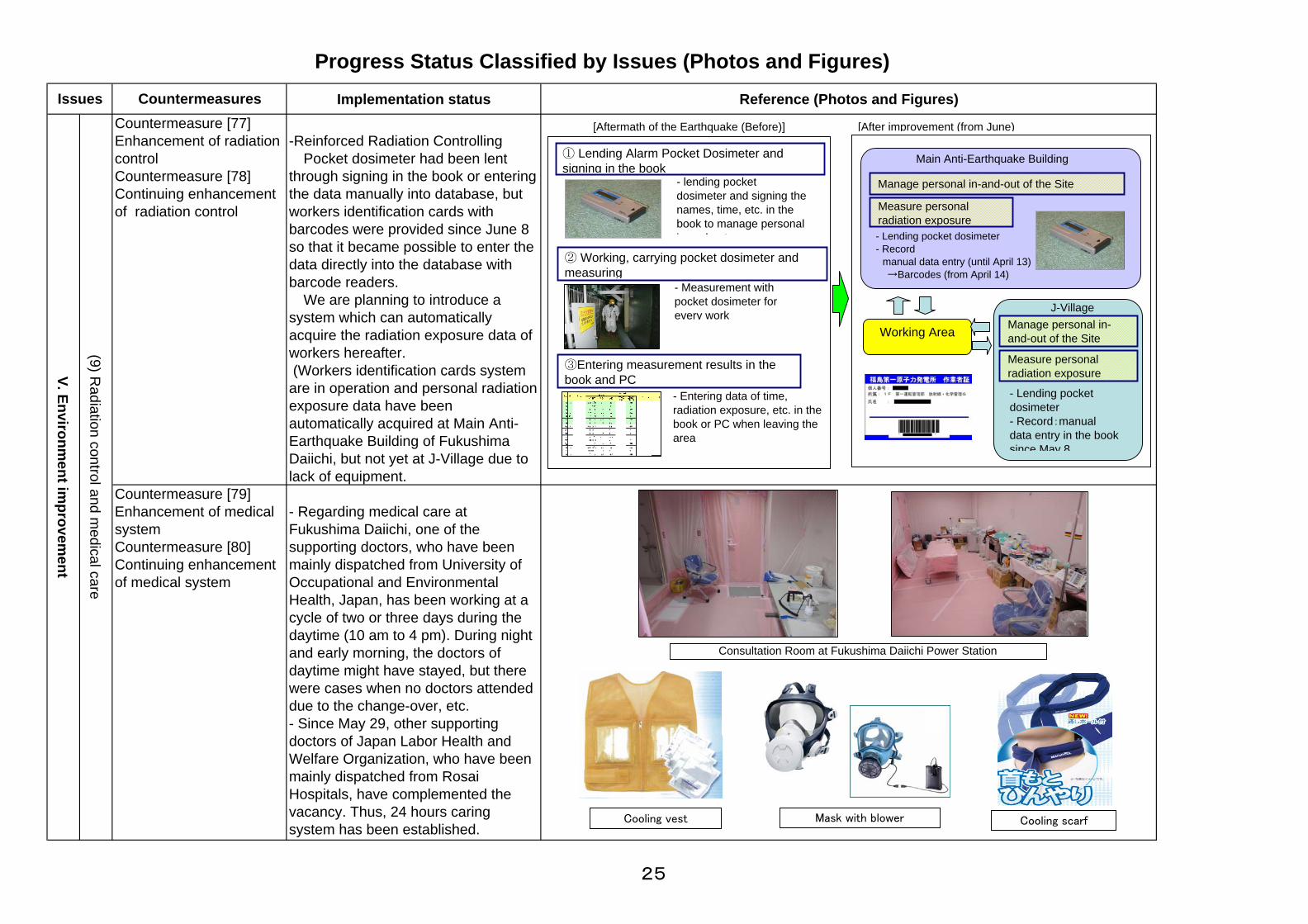
-Reinforced Radiation Controlling Pocket dosimeter had been lentthrough signing in the book or enteringthe data manually into database, butworkers identification cards withbarcodes were provided since June 8so that it became possible to enter thedata directly into the database withbarcode readers. We are planning to introduce asystem which can automaticallyacquire the radiation exposure data ofworkers hereafter. (Workers identification cards systemare in operation and personal radiationexposure data have beenautomatically acquired at Main Anti-Earthquake Building of FukushimaDaiichi, but not yet at J-Village due tolack of equipment.
(9) Radiation control and m
edical care
Countermeasure [79]Enhancement of medicalsystemCountermeasure [80]Continuing enhancementof medical system
Progress Status Classified by Issues (Photos and Figures)Issues Countermeasures
Countermeasure [77]Enhancement of radiationcontrolCountermeasure [78]Continuing enhancementof radiation control
V. Environment im
provement
- Regarding medical care atFukushima Daiichi, one of thesupporting doctors, who have beenmainly dispatched from University ofOccupational and EnvironmentalHealth, Japan, has been working at acycle of two or three days during thedaytime (10 am to 4 pm). During nightand early morning, the doctors ofdaytime might have stayed, but therewere cases when no doctors attendeddue to the change-over, etc.- Since May 29, other supportingdoctors of Japan Labor Health andWelfare Organization, who have beenmainly dispatched from RosaiHospitals, have complemented thevacancy. Thus, 24 hours caringsystem has been established.
[Aftermath of the Earthquake (Before)] [After improvement (from June)
Measure personalradiation exposure
Manage personal in-and-out of the Site
- Lending pocket dosimeter- Record manual data entry (until April 13) →Barcodes (from April 14)
Main Anti-Earthquake Building
Working Area
J-Village
Measure personalradiation exposure
Manage personal in-and-out of the Site
② Working, carrying pocket dosimeter andmeasuring
① Lending Alarm Pocket Dosimeter andsigning in the book
- lending pocketdosimeter and signing thenames, time, etc. in thebook to manage personali d t
- Measurement withpocket dosimeter forevery work
③Entering measurement results in thebook and PC
- Entering data of time,radiation exposure, etc. in thebook or PC when leaving thearea
Consultation Room at Fukushima Daiichi Power Station
- Lending pocketdosimeter- Record:manualdata entry in the booksince May 8
Cooling vest Cooling scarfMask with blower
25