Japan PUB WG, SAKE SAKE, Suimon Adventure for Knowledge Evolution Progress and Planning
Progress at the XFELs in Europe and Japan
Hans-H. Braun, PSI
48th ICFA Advanced Beam Dynamics Workshop on Future Light Sources March 1-5, 2010
SLAC National Accelerator Laboratory
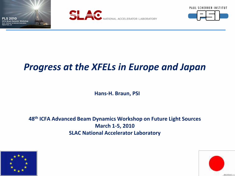
Project StatusFirst
LasingTe- λmin
Driver technology(main linac)
Overall length
FLASH running 2005(2000 TTF)
1.2 GeV 50 ÅPulsed SC1.3 GHz
315 m
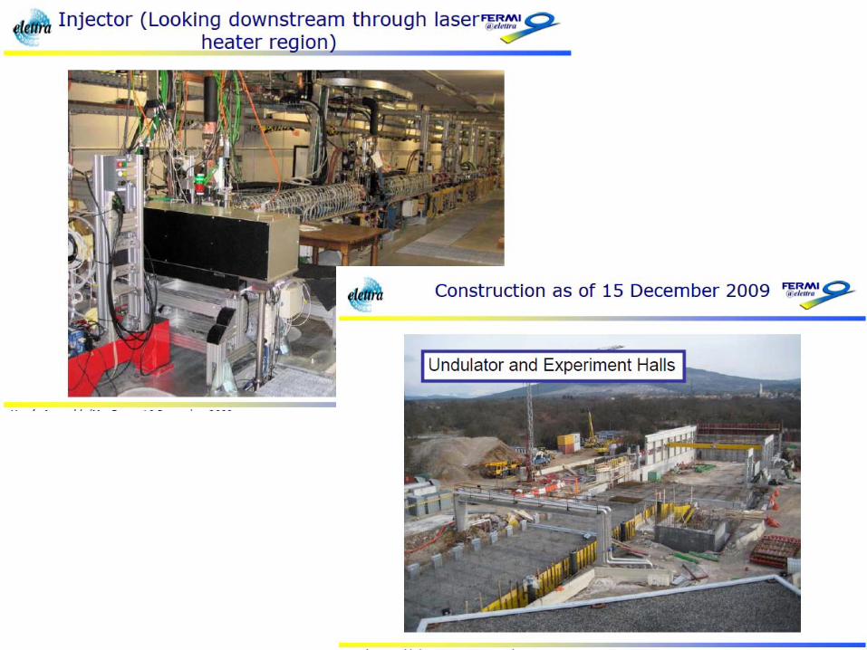
FERMI@ELETTRA construction 2010 1.8 GeV 30 ÅPulsed NC
3.0 GHz375 m
SCSS construction 2011 8 GeV 1 ÅPulsed NC
5.7 GHz750 m
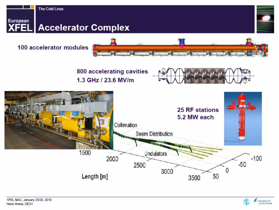
European XFEL construction 2015 17.5 GeV 1 ÅPulsed SC1.3 GHz
3400 m
SPARXWaiting for
approval2015 ? 2.4 GeV 5 Å
Pulsed NC2.85 GHz
500 m
SwissFELWaiting for
approval2016 ? 5.8 GeV 1 Å
Pulsed NC5.7 GHz
715 m
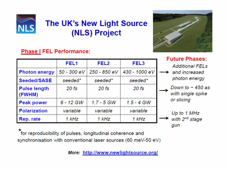
NLSWaiting for
approval? 2.25 GeV 12 Å
C.W. SC1.3 GHz
660 m
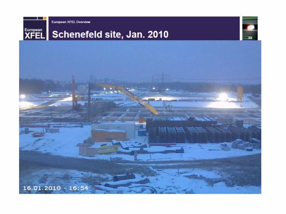
XFELs overview

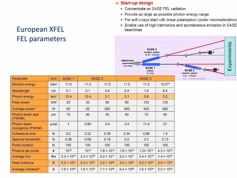
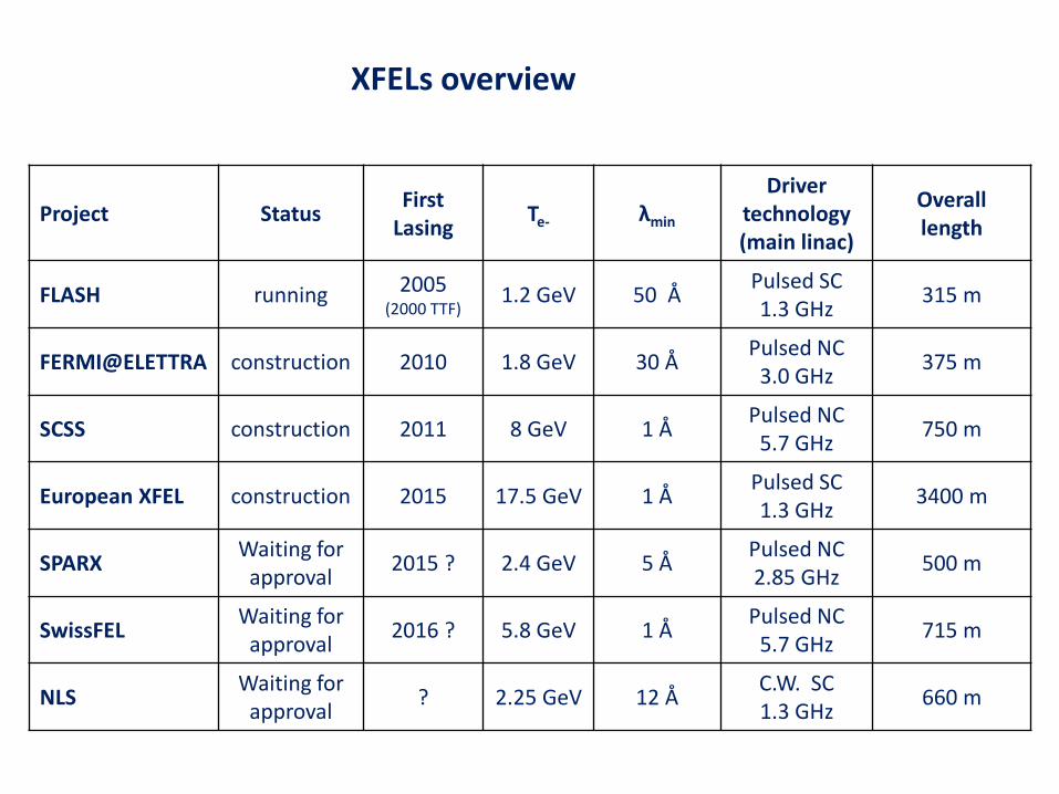
European XFEL FEL parameters

FLASH
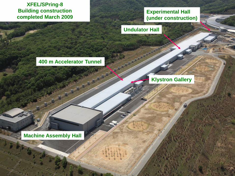
400 m Accelerator Tunnel
Undulator Hall
Experimental Hall(under construction)
Klystron Gallery
Machine Assembly Hall
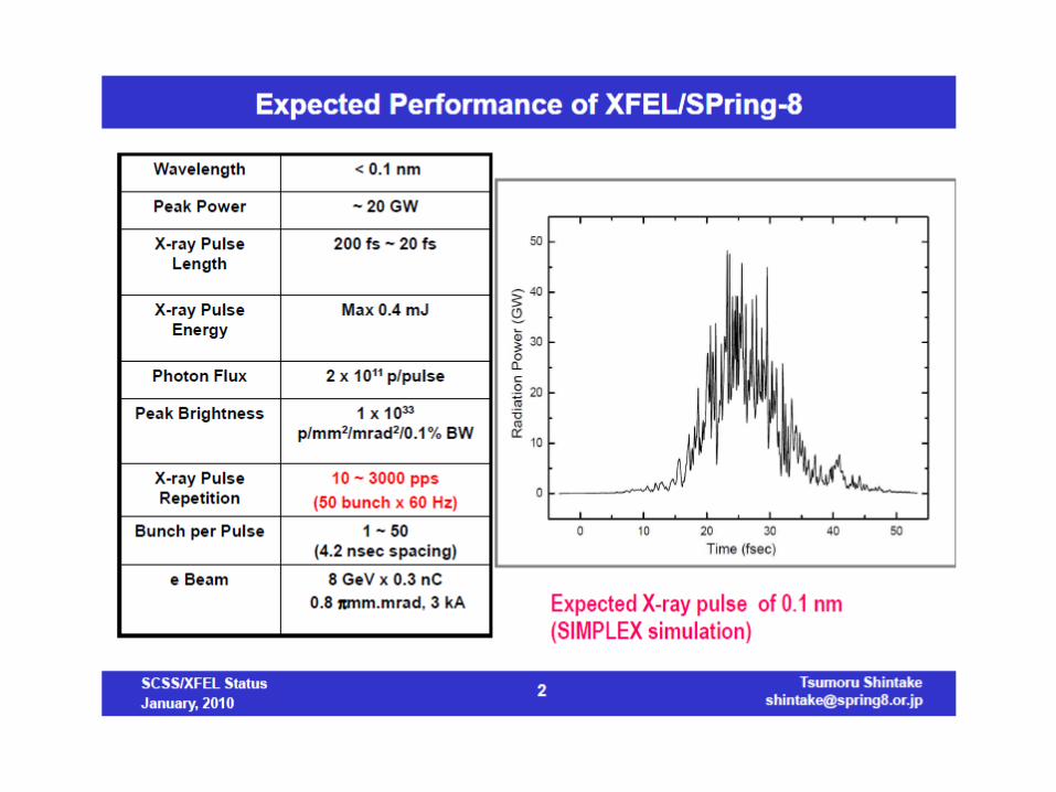
XFEL/SPring-8Building construction completed March 2009

SCSS
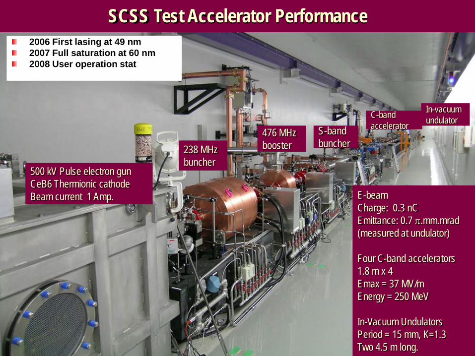
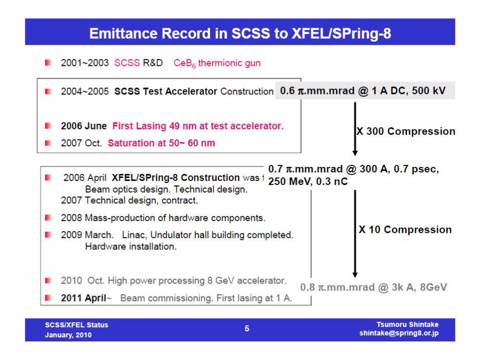
SCSS Test Accelerator Performance2006 First lasing at 49 nm2007 Full saturation at 60 nm2008 User operation stat
E-beamCharge: 0.3 nCEmittance: 0.7 π.mm.mrad(measured at undulator)
Four C-band accelerators1.8 m x 4 Emax = 37 MV/mEnergy = 250 MeV
In-Vacuum UndulatorsPeriod = 15 mm, K=1.3Two 4.5 m long.
500 kV Pulse electron gunCeB6 Thermionic cathodeBeam current 1 Amp.
238 MHz buncher
476 MHz booster
S-bandbuncher
C-bandaccelerator
In-vacuumundulator

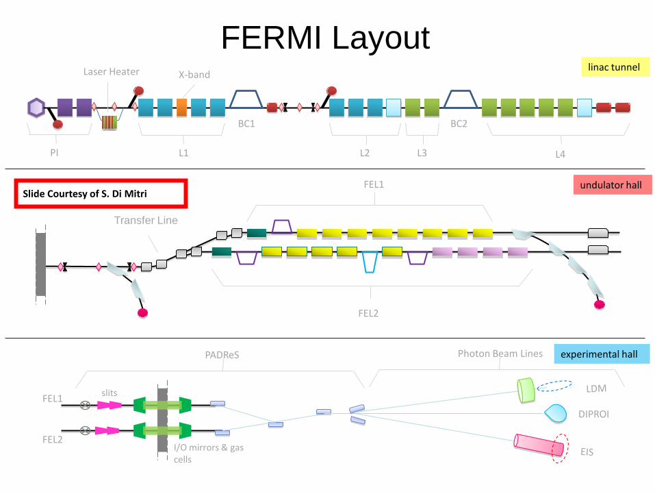
Slide Courtesy of S. Di Mitri
FEL1
FEL2I/O mirrors & gas cells
PADReS
DIPROI
Photon Beam Lines
slits
experimental hall
undulator hall
Transfer Line
FEL1
FEL2
L1
X-band
BC1
L2 L3 L4
BC2
linac tunnel
PI
Laser Heater
FERMI Layout

Parameter FEL-1 FEL-2 HGHG Stages 1 2 (“fresh bunch” in 2nd stage) Fundamental Wavelength range [nm] 100 to 20 20 to 4 (1.3 at 3rd harm.) Output pulse length (rms) [fs] < 100 20 – 100 (< 10 future goal) Bandwidth (rms) [meV] 17 (at 40 nm) 100 (at 4.2 nm) Polarization Fully Variable Fully Variable Repetition rate [Hz] 50 50 Peak power [GW] 1 to >5 0.5 to 2 Harmonic peak power (% of fundamental) ~2 ~0.2 (at 4.2 nm) Photons per pulse 1014 (at 40 nm) 2x10¹² (at 4.2 nm) Pulse-to-pulse stability ≤ 30 % ~40 % Pointing stability [µrad] < 20 < 20 Virtual waist size [µm] 250 (at 40 nm) 120 Divergence (rms, intensity) [µrad] 50 (at 40 nm) 10 (at 4.2 nm)
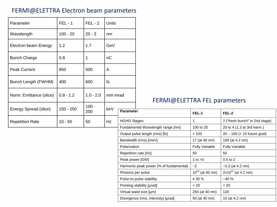
FERMI@ELETTRA Electron beam parameters
Parameter FEL - 1 FEL - 2 Units
Wavelength 100 - 20 20 - 3 nm
Electron beam Energy 1.2 1.7 GeV
Bunch Charge 0.8 1 nC
Peak Current 850 500 A
Bunch Length (FWHM) 400 600 fs
Norm. Emittance (slice) 0.8 - 1.2 1.0 - 2.0 mm mrad
Energy Spread (slice) 150 - 250 100 -200 keV
Repetition Rate 10 - 50 50 Hz
FERMI@ELETTRA FEL parameters
Parameter FEL-1 FEL-2
HGHG Stages 1 2 (“fresh bunch” in 2nd stage)
Fundamental Wavelength range [nm] 100 to 20 20 to 4 (1.3 at 3rd harm.)
Output pulse length (rms) [fs] < 100 20 – 100 (< 10 future goal)
Bandwidth (rms) [meV] 17 (at 40 nm) 100 (at 4.2 nm)
Polarization Fully Variable Fully Variable
Repetition rate [Hz] 50 50
Peak power [GW] 1 to >5 0.5 to 2
Harmonic peak power (% of fundamental) ~2 ~0.2 (at 4.2 nm)
Photons per pulse 1014 (at 40 nm) 2x10¹² (at 4.2 nm)
Pulse-to-pulse stability ≤ 30 % ~40 %
Pointing stability [µrad] < 20 < 20
Virtual waist size [µm] 250 (at 40 nm) 120
Divergence (rms, intensity) [µrad] 50 (at 40 nm) 10 (at 4.2 nm)
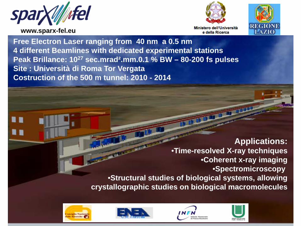
Free Electron Laser ranging from 40 nm a 0.5 nm4 different Beamlines with dedicated experimental stationsPeak Brillance: 1027 sec.mrad².mm.0.1 % BW – 80-200 fs pulses Site : Università di Roma Tor VergataCostruction of the 500 m tunnel: 2010 - 2014
Applications:•Time-resolved X-ray techniques
•Coherent x-ray imaging •Spectromicroscopy
•Structural studies of biological systems, allowing crystallographic studies on biological macromolecules
www.sparx-fel.eu

www.sparx-fel.eu

S-band Gun
Velocity Bunching
Long Solenoids
Diagnostic and
Matching
Seeding
THz Source
150 MeV S-band
linac
12 mUndulators
λu = 2.8 cm
Kmax = 2.2
λr = 500 nm
15 mQuickTime™ and a
decompressorare needed to see this picture.

Aramis: 1-7 Å hard X-ray SASE FEL, In-vacuum , planar undulators with variable gap.
Athos: 7-70 Å soft X-ray FEL for SASE & Seeded operation . APPLE II undulators with variable gap and full polarization control.
D’Artagnan: FEL for wavelengths above Athos, seeded with an HHG source. Besides covering the longer wavelength range, the FEL is used as the initial stage of a High Gain Harmonic Generation (HGHG) with Athos as the final radiator.
SwissFEL
704 m
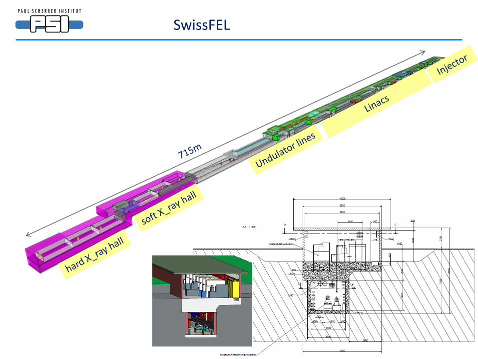
SwissFEL
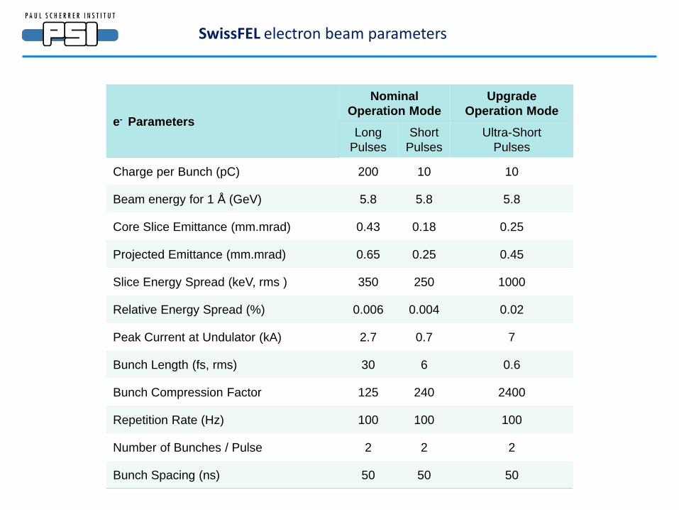
e- Parameters
Nominal Operation Mode
Upgrade Operation Mode
Long Pulses
Short Pulses
Ultra-Short Pulses
Charge per Bunch (pC) 200 10 10
Beam energy for 1 Å (GeV) 5.8 5.8 5.8
Core Slice Emittance (mm.mrad) 0.43 0.18 0.25
Projected Emittance (mm.mrad) 0.65 0.25 0.45
Slice Energy Spread (keV, rms ) 350 250 1000
Relative Energy Spread (%) 0.006 0.004 0.02
Peak Current at Undulator (kA) 2.7 0.7 7
Bunch Length (fs, rms) 30 6 0.6
Bunch Compression Factor 125 240 2400
Repetition Rate (Hz) 100 100 100
Number of Bunches / Pulse 2 2 2
Bunch Spacing (ns) 50 50 50
SwissFEL electron beam parameters

Photon
Nominal Operation Mode
Upgrade Operation
Mode
Long Pulses
Short Pulses
Ultra-Short Pulses
Undulator Period (mm) 15 15 15
Undulator Parameter 1.2 1.2 1.2
Laser Wavelength (Å) 1 1 1
Maximum Saturation Length (m) 50 50 50
Saturation Pulse Energy (µJ) 60 3 6
Effective Saturation Power (GW) 2 0.6 11
Photon Pulse Length at 1 Å (fs, rms) 13 2.1 0.3
Number of Photon at 1 Å (×109) 31 1.7 3.2
Bandwidth (%) 0.03 0.04 0.05
Peak Brightness(# photons.mm-2.mrad-2.s-1/0.1% bandwidth) 3.1032 1.1032 1,3.1033
Average Brightness (# photons.mm-2.mrad-2.s-1/0.1% bandwidth) 1.1021 5,7.1018 7,5.1018
SwissFEL photon beam parameters(Aramis for 1 Å)
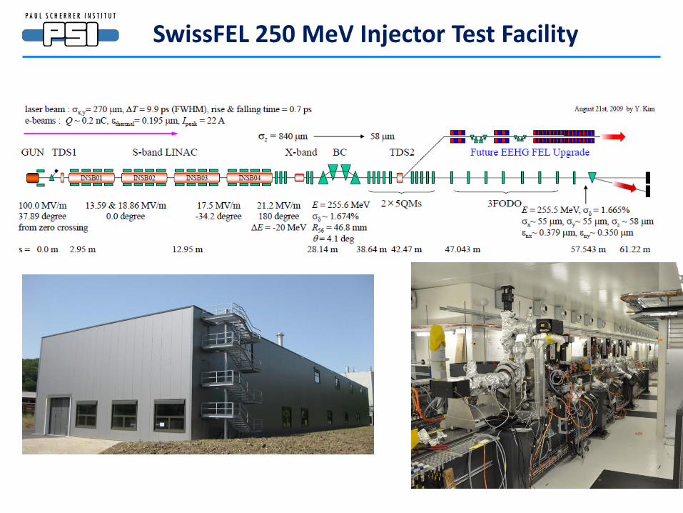
SwissFEL 250 MeV Injector Test Facility

Today

Project TypeGun
technologyLaser type
Cathode material
FLASH RF gunPulsed NC
1.3 GHzNd:YLF
4th harmonicCs2Te
SCSSThermionic
Diode with SHBPulsed 500kV
with SHBn.a. CeB6
FERMI@ELETTRA RF gunPulsed NC
3.0 GHzTi:Sa
3rd harmonicCu
European XFEL RF gunPulsed NC
1.3 GHzYb:YAG
4th harmonicCs2Te
SPARC X RF gunPulsed NC2.85 GHz
Ti:Sa3rd harmonic
Cu
SwissFEL RF gunPulsed NC
3.0 GHzTi:Sa
3rd harmonicCu
NLS RF gunC.W. SC1.3 GHz
? Cs2Te
Injectors

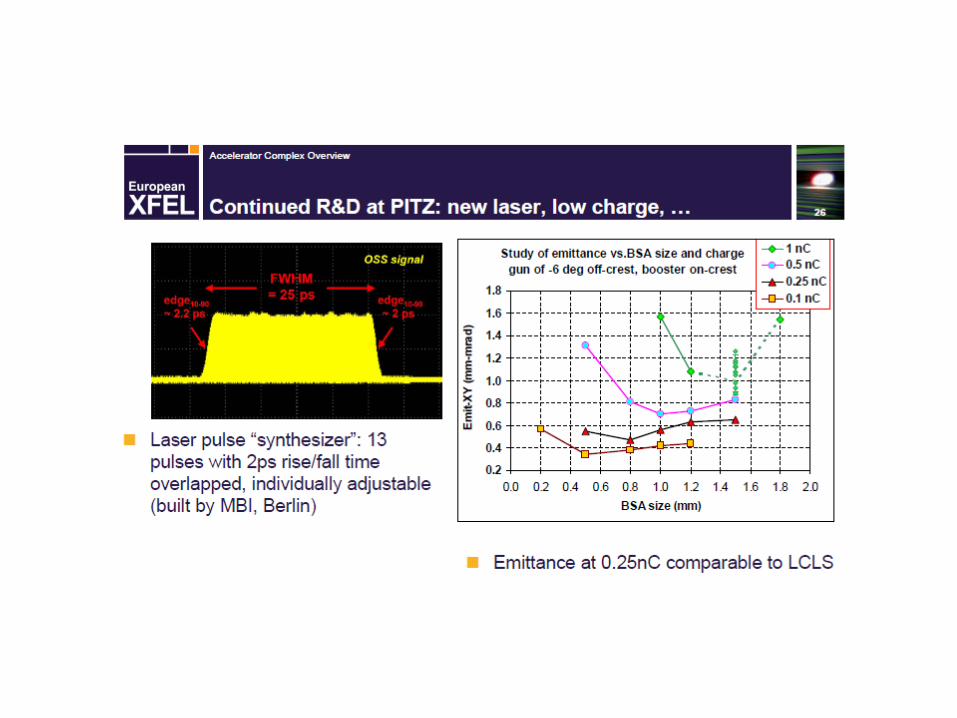

From PITZ, SSCS and LCLS injector data one could infer:No matter what you choose as injector, if you work hard enough you get
ε ≈ 1 μm qB½ (with qB in nC )
Open injector R&D issues
• how to get the same ε/qB½ for c.w. operation
• how to improve one order of magnitude in ε/qB½

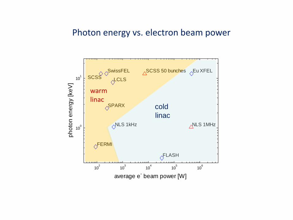
102
103
104
105
106
100
101
FLASH
FERMI
Eu XFEL
SPARX
SwissFEL
NLS 1kHz
LCLS SCSS
average e- beam power [W]
phot
on e
nerg
y [k
eV]
SCSS 50 bunches
NLS 1MHz
Photon energy vs. electron beam power
coldlinac
warmlinac


Cost comparison linac technologiesorWhy doesn’t everybody take s.c. & c.w.
Technology Linac investment cost w/o building
Typical gradient Electric consumption
Pulsed n.c. with SLED 10 M€/GeV 20 MV/m (S-band)
30 MV/m (C-band)0.5 MW/GeV
Pulsed superconducting 20 M€/GeV 24 MV/m 0.5 MW/GeV
c.w. superconducting ? 30 M€/GeV ? 18 MV/m 5 MW/GeV
Beware! This is not exact science !
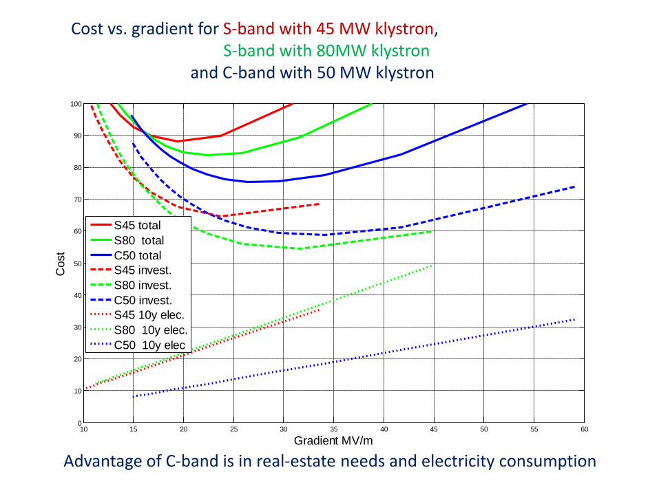
Cost vs. gradient for S-band with 45 MW klystron, S-band with 80MW klystron
and C-band with 50 MW klystron
Advantage of C-band is in real-estate needs and electricity consumption
10 15 20 25 30 35 40 45 50 55 600
10
20
30
40
50
60
70
80
90
100
Gradient MV/m
Cos
t
S45 totalS80 totalC50 totalS45 invest.S80 invest.C50 invest.S45 10y elec.S80 10y elec.C50 10y elec

Talk Matthias FuchsThursday 10:00 - 10:30
Many thanks to
Reinhard Brinkmann, Jörg Rossbach, Massimo Ferrario, Florian Grϋner, Stephen Milton, Tsumoru Shintake, Richard Walker
for providing information and materials