Profinia Protein Purification System - Bio-Rad · 2014-07-15 · Protein Purification System...
224
Profinia ™ Protein Purification System Instruction Manual For Technical Service Call Your Local Bio-Rad Office or in the U.S. Call 1-800-4BIORAD (1-800-424-6723)
Transcript of Profinia Protein Purification System - Bio-Rad · 2014-07-15 · Protein Purification System...

Profinia™
Protein Purification System
Instruction Manual
For Techn ica l Serv ice Ca l l Your Loca l B io -Rad Of f i ce o r in the U.S. Ca l l 1-800-4BIORAD (1 -800-424-6723)

Contact Bio-RadBio-Rad Laboratories, Inc.2000 Alfred Nobel DriveHercules, CA 94547
Phone: (510) 741-1000Fax: (510) 741-5811
Bio-Rad Technical Support The Bio-Rad Technical Support department in the United States is open Monday–Friday,6:00 a.m. to 5:00 p.m., Pacific Standard Time. Worldwide technical support is available onthe Web at http://www.consult.bio-rad.com/
Phone: (800) 424-6723, option 2, option 3; (510) 741-6910, option 2, option 3
Fax: (510) 741-5802
E-mail: [email protected] (U.S.) [email protected] (international) Web: http://www.bio-rad.com/
Legal Notices No part of this publication may be reproduced or transmitted in any form or by any means,electronic or mechanical, including photocopy, recording, or any information storage orretrieval system, without permission in writing from Bio-Rad Laboratories, Inc.
Bio-Rad reserves the right to modify its products and services at any time. This user guideis subject to change without notice.
Although prepared to ensure accuracy, Bio-Rad assumes no liability for errors or omissions,or for any damages resulting from the application or use of this information.
Purification and preparation of fusion proteins and affinity peptides containing at least twoadjacent histidine residues may require a license under US patent 5,284,933 and USpatent 5,310,663, including foreign patents (assignee: Hoffmann-La Roche).
Expression and purification of GST fusion proteins may require a license under US patent5,654,176 (assignee: Chemicon International).
Benzonase is a trademark of Merck KGAA Corp. Excel, Microsoft, Windows 2000 and XPare trademarks of Microsoft Corporation. Pentium is a trademark of Intel Corporation.Tefzel is a trademark of E.I. du Pont de Nemours and Co. Vaseline is a trademark ofUnilever Supply Chain Inc.
Copyright © 2007 by Bio-Rad Laboratories, Inc. All rights reserved.

Caution!
Please read all safety-related information before operating the Profinia system.
This instrument is for laboratory use only.
Always connect the power supply to a 3-prong, grounded AC outlet using the AC powercord provided with the Profinia instrument. Do not use an adaptor to connect to a 2-terminaloutlet.
The right-side back panel is easily removable for access to user-serviceable parts. Neverremove any other outer casings of the Profinia instrument. Call your local Bio-Rad office forinstrument service.
Do not operate the Profinia instrument in extreme humidity (>95%), or in a condensingenvironment.
When taking the Profinia instrument into a cold room, the unit can be operated immediately.However, when removing the unit from the cold room, let it warm up to room temperaturefor a minimum of 2 hours before switching on the power. This avoids damage from possiblecondensation.
The Profinia instrument is not designed for use with flammable liquids. Flammable liquidsshould never be placed in either the buffer or sample inlets of the instrument.
This product conforms to Class A standards for Electromagnetic Emissions intended forlaboratory equipment applications. It is possible that emissions from this product may interfere with some sensitive appliances when placed nearby or on the same circuit asthose appliances. The user should be aware of this potential and take appropriate measuresto avoid interference.
This Bio-Rad instrument is designed and certified to meet EN-61010 safety standards; EN-61010-certified products are safe to use when operated in accordance with this instruction manual.
This instrument should not be modified or altered in any way. Alteration of this instrumentwill void the manufacturer’s warranty, void EN-61010 certification, and create a potentialsafety hazard for the user.
Bio-Rad is not responsible for any injury or damage caused by the use of this instrument forpurposes other than those for which it is intended, or by modifications of the instrument notperformed by Bio-Rad or an authorized agent.
!
!!

Table of ContentsPage
Section 1 Profinia Protein Purification System Description .......................11.1 Profinia System Overview..........................................................................11.2 Key Features of the Profinia System..........................................................11.3 System Components and Optional Accessories.........................................21.4 Related Consumables and Products..........................................................41.5 About This Guide .......................................................................................4
1.5.1 Conventions....................................................................................4
Section 2 Installation Procedures.................................................................52.1 System Installation.....................................................................................52.2 First-Time Use of the Profinia System........................................................8
2.2.1 Preparing the Instrument for Cleaning.............................................82.2.2 Selecting the First-Time Cleaning Procedure ..................................92.2.3 Setting the Local Date and Time...................................................102.2.4 Validating the System ...................................................................10
Section 3 Key Terms and Definitions .........................................................143.1 Bio-Rad Methods.....................................................................................143.2 Program Methods ....................................................................................143.3 Toolbar Navigation Buttons......................................................................153.4 System Status Indicator Definitions..........................................................163.5 Alphanumeric and Numeric Keypads .......................................................17
3.5.1 Alphanumeric Keypad...................................................................173.5.2 Numeric Keypad ...........................................................................17
Section 4 Profinia System Quick Guide .....................................................194.1 Profinia Installation...................................................................................194.2 Profinia System Quick Guide ...................................................................23
Section 5 Home Screen Overview ..............................................................27
Section 6 Bio-Rad Methods.........................................................................296.1 Selecting Method System ........................................................................326.2 Selecting Method Type and Options ........................................................326.3 Selecting Sample Options........................................................................34
6.3.1 .........................Selecting Sample Flow Rate and Wash Time346.3.2 Selecting Sample Incubation Time................................................35
6.4 Entering Run and Sample Information .....................................................366.4.1 Adding or Editing Run and Sample Information.............................386.4.2 Adding Lot Number Tracking Information......................................38
6.5 Installing Reagents, Sample Tubes, and Fraction Tubes .........................396.5.1 Loading Buffers ............................................................................416.5.2 Installing Sample Tubes................................................................446.5.3 Installing Fraction Collection Tubes...............................................45
6.6 Installing Cartridges .................................................................................466.6.1 Preparing for Cartridge Installation................................................466.6.2 Setting Up Cartridge Positions for Priming ....................................476.6.3 Priming the Cartridge Lines...........................................................486.6.4 Installing Cartridges ......................................................................486.6.5 Installing the Sample Loop (Desalting-Only Methods) ...................52
6.7 Starting the Run.......................................................................................54
i

6.7.1 Viewing Steps...............................................................................556.7.2 Viewing Real-Time Data With Profinia Software............................566.7.3 Clearing System Memory to Start the Run ....................................57
6.8 Monitoring Run Progress .........................................................................586.8.1 Run in Progress Screen................................................................586.8.2 Peak Detection .............................................................................596.8.3 Collecting the Purified Sample ......................................................616.8.4 Canceling or Pausing a Run .........................................................626.8.5 Completing the Run ......................................................................62
6.9 Preparing System for End-of-Run Cleaning .............................................626.9.1 Preparing for Line Cleaning ..........................................................626.9.2 System Cleaning in Progress........................................................63
6.10 Performing End-of-Run Procedures .........................................................636.10.1 Exporting Data to a Computer.......................................................646.10.2 Performing Final Run Procedures.................................................64
Section 7 Program Methods........................................................................687.1 Selecting Method System ........................................................................697.2 Selecting Method Type and Options ........................................................707.3 Entering Run and Sample Information .....................................................71
7.3.1 Adding or Editing Run and Sample Information.............................737.3.2 Adding Lot Number Tracking Information......................................73
7.4 Editing and Saving a Program Method.....................................................747.4.1 Editing a Program Method ............................................................747.4.2 Saving a Program Method ............................................................77
7.5 Installing Reagents, Sample Tubes, and Fraction Tubes .........................787.5.1 Preparing and Installing Reagents and Samples for the
Purification Run ............................................................................807.6 Installing Cartridges .................................................................................80
7.6.1 Installing the Sample Loop (Desalting-Only Methods) ...................817.7 Viewing Real-Time Data With Profinia Software.......................................837.8 Starting the Run.......................................................................................83
7.8.1 Viewing Steps...............................................................................847.8.2 Running the Manual Prime Function .............................................847.8.3 Clearing System Memory to Start Run..........................................85
7.9 Monitoring Run Progress .........................................................................857.9.1 Peak Detection .............................................................................857.9.2 Collecting Purified Sample............................................................867.9.3 Completing the Run ......................................................................86
7.10 Preparing System for End-of-Run Cleaning .............................................867.10.1 Preparing for Line Cleaning ..........................................................867.10.2 System Cleaning in Progress Screen............................................86
7.11 Performing End-of-Run Procedures .........................................................867.11.1 Exporting Data to a Computer.......................................................877.11.2 Performing Final Run Procedures.................................................87
Section 8 Saved Methods............................................................................898.1 Retrieving Saved Methods.......................................................................898.2 Selecting Saved Methods ........................................................................908.3 Running Saved Methods..........................................................................90
Section 9 Data and Utilities .........................................................................929.1 Exporting Data & Real-Time Data Acquisition ..........................................92
9.1.1 Exporting Data to USB Portable Memory Device ..........................92
ii

9.1.2 Real-Time Data Transfer to Profinia Software...............................939.2 System Utilities ........................................................................................93
9.2.1 Calibrating Touch Screen .............................................................949.2.2 Checking Pump Flow Rate ...........................................................949.2.3 Calibrating UV Monitors ................................................................959.2.4 Calibrating Conductivity Monitor....................................................969.2.5 Adjusting Peak Detection Sensitivity .............................................979.2.6 Calibrating pH Probe ....................................................................979.2.7 Calibrating Air Detection System...................................................989.2.8 Calibrating Pressure .....................................................................98
9.3 Diagnostic/Maintenance Functions ..........................................................989.3.1 Displaying Firmware Versions.......................................................999.3.2 Setting and Operating Instrument Manually ..................................999.3.3 Setting Time and Date ................................................................1049.3.4 Cleaning Sample Lines...............................................................1059.3.5 Cleaning Fraction Lines ..............................................................1069.3.6 Cleaning Buffer Lines..................................................................1079.3.7 Washing System With Ethanol....................................................1089.3.8 Cleaning Inlet and Outlet Lines ...................................................1099.3.9 Cleaning Pump Check Valves.....................................................1109.3.10 Washing System With NaOH......................................................1119.3.11 Cleaning Inline Check Valve .......................................................1129.3.12 Affinity Cartridge Cleaning in Place.............................................1129.3.13 Desalting Cartridge Cleaning in Place.........................................1139.3.14 Selecting End of Sample/Reagent Detection (Air Sensors) .........1149.3.15 Selecting Method Temperature...................................................1159.3.16 Select Display Contrast...............................................................116
Section 10 Profinia Purification Kits...........................................................11710.1 Introduction............................................................................................117
10.1.1 Background ................................................................................11710.1.2 Product Information ....................................................................11710.1.3 Equipment and Materials Required .............................................11810.1.4 Storage Conditions .....................................................................118
10.2 Native IMAC Purification and Buffer Kits ................................................11810.3 Denaturing IMAC Purification and Buffer Kits .........................................12010.4 GST Purification and Buffer Kits.............................................................12210.5 Desalting Buffer and Separation Kits......................................................123
Section 11 Connecting External Components...........................................12511.1 pH Monitor .............................................................................................12511.2 Larger Buffer, Sample, and Fraction Containers ....................................128
11.2.1 External Buffer Containers..........................................................12811.2.2 External Sample Containers .......................................................12911.2.3 External Fraction Collection Containers ......................................130
11.3 Profinia Cooling Accessory ....................................................................13011.4 Connecting non-Bio-Rad Cartridges ......................................................132
Section 12 Software.....................................................................................13312.1 Operating Requirements........................................................................13312.2 Software Structure .................................................................................13312.3 Transferring Data to Profinia Software ...................................................134
12.3.1 Real-Time Data Transfer ............................................................13412.3.2 Portable Memory Device Data Transfer ......................................135
iii

12.4 Viewing Run Data Files..........................................................................13512.4.1 Opening Files in Profinia Software ..............................................13512.4.2 Chromatogram Overview............................................................13612.4.3 Eliminating Run Parameters Displayed.......................................13612.4.4 Customizing Chromatogram Display Options..............................136
12.5 Reports..................................................................................................13912.5.1 Standard Reports........................................................................13912.5.2 Custom Reports..........................................................................139
12.6 Exporting Chromatograms .....................................................................14012.7 Exporting Data Files...............................................................................14012.8 Help Information ....................................................................................140
Section 13 Care and Maintenance ..............................................................14113.1 Cleaning the Instrument.........................................................................141
13.1.1 Daily Cleaning ............................................................................14113.1.2 Weekly Cleaning.........................................................................14113.1.3 Storage.......................................................................................14113.1.4 System Cleaning Procedures......................................................14213.1.5 Cleaning Touch Screen ..............................................................143
13.2 Maintenance..........................................................................................14413.2.1 Pump Check Valves ...................................................................14513.2.2 Pump Seals ................................................................................14913.2.3 UV Monitor Lamp........................................................................15313.2.4 UV Monitor Flow Cells ................................................................15813.2.5 Buffer and Sample Inlet Tubes....................................................16113.2.6 Tubings and Fittings ...................................................................16113.2.7 Inline Filter ..................................................................................16613.2.8 Power Conditioning.....................................................................167
Appendix A Profinia System Specifications............................................168
Appendix B Profinia System Ordering Information.................................169
Appendix C Profinia System Troubleshooting ........................................172
Appendix D Profinia System Error Messages .........................................176
Appendix E Sample Preparation ..............................................................177
Appendix F Sample Preparation, Application, and Analysis Tips..........179
Appendix G Profinia System Annual Maintenance .................................184
Appendix H Profinia Instrument Cleaning and Maintenance Log ..........186
Appendix I Profinia Protein A and G Method Manual ............................187
Appendix J Profinia Profinity eXact Method Manual ..............................194
Appendix K Profinia Program Methods Planning Worksheets...............202
iv

Section 1Profinia™ Protein Purification System Description
1.1 Profinia System OverviewThe Profinia protein purification system is an automated chromatography system that provides a simple solution for the purification and desalting of milligram amounts of affinity-tagged proteins. The Profinia system is easy to operate, allowing users to concentrate onsolving the questions posed by science, rather than spending time performing separationtechniques. In the Profinia system, the cartridges, tubes, fittings, and Bio-Rad methodshave all been optimized and are built in, so no expertise in chromatography is required toset up the instrument or perform affinity purification.
The Profinia system requires minimal user interaction; a user-friendly touch screen providesguidance through all setup, purification, and run completion procedures. The yield and purity of proteins obtained using the Profinia system are comparable to those from morecomplicated or labor-intensive manual methods such as gravity-flow chromatography. Usershave two options for running purification methods: Bio-Rad methods with automated templatesfor common GST, IMAC, Protein A and G purifications, Profinity eXact purification or programmethods created by editing the Bio-Rad method templates. Both Bio-Rad and program methodsinclude automatic desalting (not all Bio-Rad methods include desalting) as well as automaticsystem and cartridge cleaning. Both types of methods also provide a data record of resultsthat can either be viewed and recorded at the end of the run, exported to a computer withProfinia software for data review, or viewed in real time on a computer with Profinia software.
A variety of purification, buffer, and starter kits are available for use with the Profinia instrument. Profinia purification kits include cartridges, concentrated reagents, and buffers,and are optimized for use with Bio-Rad methods. Profinia buffer kits include all concentratedreagents necessary to run a Bio-Rad method. Profinia starter kits are available for GST andnative IMAC methods. These kits include cartridges, concentrated reagents, and controllysate to perform a Bio-Rad method. All kit components are clearly labeled to show wherethey should be placed in the instrument, and formulations of all buffers are listed for use inreports.
Buffer and cartridge kits, optimized methods, and instrument automation ensure high qualityand reproducible purification purity and yield, along with significant time savings. Fromsetup to purification runs to exportable data files, the Profinia system is intuitive and easy tooperate, allowing researchers at any level of chromatography expertise to move quicklyand efficiently through purifying affinity-tagged proteins to downstream protein-basedexperiments.
1.2 Key Features of the Profinia System• Integrated system design — no need to assemble tubing and fittings or pack
chromatography columns
• Easy instrument setup — plug in the instrument and load reagents
• Simple system operation — automated purification and desalting of affinity-taggedproteins
• Automatic calculations — estimated purified protein yield and concentration displayedat end of run
• Touch-screen interface — guided instrument and method setup; displays current runinformation
1

2
• Built-in cleaning and storage steps — automated system cleaning ensures continuedpeak instrument performance
• Purification kits — affinity and desalting cartridges, buffers, and solutions optimizedfor Bio-Rad methods
• Optional cooling accessory — samples and fractions of purified samples stay coldwithout keeping the instrument in a cold room or using a cold box
• Optional Profinia software — real-time data and customized reports can be displayed, used forbasic protein comparisons and analysis, and incorporated into lab notebooks and presentations
1.3 System Components and Optional AccessoriesThe Profinia protein purification system components (see Figure 1.1) are:
Profinia instrument — shipment box #1
Profinia accessory kit — shipment box #2; includes:
• Profinia buffer bottle starter pack — 4 x 125 ml and 4 x 250 ml empty bottles
• Profinia buffer lids — pack of eight lids
• Profinia lids for 15 ml sample conical tubes — pack of two lids
• Profinia lids for 50 ml sample conical tubes — pack of two lids
• Profinia waste/diluent (water) bottle pack — 2 x 2 L bottles
• Profinia cleaning tray — placed in the fraction collection area to collect liquid byproducts from line cleaning and system wash procedures
• Inline filter — 12 replacement filters
Profinia starter kit — shipment box #3; choice of native IMAC or GST starter kit, includes1 ml affinity cartridge, 10 ml desalting cartridge, vial of Profinia control lysate, and a completebuffer set for native IMAC or GST purification
Fig. 1.1. Profinia purification system components.
IMAC or GSTstarter kit
Cleaningtray
Profiniainstrument
Buffer bottles
Waste anddiluent(water) bottles
Buffer andsample lids
Inline filter

The following accessories and components can be ordered separately for use with theProfinia system:
• Profinia control lysate — dual-tag (histidine and GST) protein that can be used to validate the performance of the Profinia system
• Profinia software — provides data reporting and basic analysis of run results
• Cooling accessory — holds two 15 ml or 50 ml conical tubes (holds two samples and/ortwo purified protein fraction tubes), and is designed to keep samples or purified proteincooled below 4°C when a cold room environment is not available
• Profinia purification kits — prepackaged cartridges, buffers, and reagents, for usewith Bio-Rad methods. Bottles and accessories are clearly labeled to indicate positioningin the Profinia instrument (see Table 1.1)
• Profinia buffer kits — prepackaged buffer and reagents for use with Bio-Rad methods;cartridges are not included. Bottles and accessories are clearly labeled to indicate positioning in the Profinia instrument (see Table 1.1)
• Bio-Scale™ Mini cartridges — IMAC, GST, Protein A cartridges (1 ml and 5 ml),Profinity eXact cartridges (1 ml and 5 ml), and desalting cartridges (10 ml and 50 ml)
• Desalting sample loops — required for use in desalting methods only; available in 2 mland 10 ml sizes. This accessory is not required for Bio-Rad methods that include affinityand desalting (for example, native IMAC and desalting or GST and desalting)
• Bottle starter pack — replacement empty buffer bottles (4 x 125 ml and 4 x 250 ml bufferbottles, eight buffer lids)
• Waste/diluent bottle set — replacement waste and diluent bottles with caps and tubing
Table 1.1. Types of Profinia purification and buffer kits.
Method Purification Kit Buffer KitNative IMAC* 1 ml or 5 ml affinity cartridge Buffers and reagents for native
plus 10 ml or 50 ml desalting IMAC and desalting methodscartridge configurations
Denaturing IMAC 1 ml or 5 ml affinity cartridge Buffers and reagents for configurations; desalting does denaturing IMAC methodsnot apply to this kit
GST** 1 ml or 5 ml affinity cartridge Buffers and reagents for GSTplus 10 ml or 50 ml desalting and desalting methodscartridge configurations
Desalting 10 ml or 50 ml cartridge Buffers and reagents for configurations desalting-only methods
* IMAC = immobilized metal affinity chromatography.
** GST = glutathione S-transferase.
3

1.4 Related Consumables and ProductsThe following related products are available from Bio-Rad (see Appendix B for a list ofordering information and catalog numbers):
• Detection antibodies — used for histidine (His) and glutathione S-transferase (GST)
• Bacterial/Lysis/Extraction reagent — chemical lysis buffer used to prepare samplelysates; without the need for sonication. This reagent is not used in the instrument
• Profinia control lysate — lyophilized sample prepared with a His- and GST-taggedprotein from E. coli
• Profinity eXact Antibody Reagent — a mouse monoclonal antibody used to detectexpression of the target protein
The following related products are available from other vendors:
• Conical tubes — 15 ml and 50 ml, for use in the sample and fraction collection positions
Note: Not all tubes made by all vendors will fit properly in the Profinia instrument; Bio-Radrecommends the following vendor tubes: 50 ml, VWR catalog #21008-178 and #20171-029and BD Biosciences catalog #352098; 15 ml, VWR catalog #20171-025 and BDBiosciences catalog #352097.
1.5 About This Guide
1.5.1 Conventions
The following messages in bold are used to highlight critical information and remindersthroughout this document:
• Warning — indicates an action that can result in an irretrievable loss of sample or data
• Note — serves as a reminder, repeating relevant information from previous sections or offering advice helpful to achieving desired results
• Important — indicates information critical to achieving optimal results
Touch-screen button commands are indicated by initial capitalization, for example: Touchthe Select button.
Screen names are indicated by initial capitalization, for example: You will proceed to theData/Utilities screen.
Functions located within menus on touch screens are indicated by initial capitalization andenclosed in double quotation marks, for example: Highlight the “System Ethanol Wash”option.
4

Section 2Installation Procedures
2.1 System Installation
The Profinia™ purification system is shipped in three boxes. The largest box contains theinstrument wrapped in foam-insert protective packaging; the smaller boxes contain all theadditional components sold as part of the Profinia system.
Warning: Use care to follow the instrument unpacking procedures described below.Improper handling of the instrument can cause damage.
To unpack and set up the Profinia system:
1. Open the smaller boxes containing the system components and make sure all partswere received (see section 1.3 for a list of all components included with the Profiniapurification system).
2. Set the larger box containing the Profinia instrument on the floor with the arrows pointingup (Figure 2.1).
Fig. 2.1. Profinia instrument box.
3. Use scissors or wire cutters to cut the plastic straps.
4. Use a large screwdriver or similar tool to remove the staples (if present) along thesides, near the bottom of the box.
5

Fig. 2.2. Three boxes containing Profinia instrument and components.
5. Use the handles cut into the side of the top section of the box to lift it off the instrument(Figure 2.3).
6. Remove the protective packaging from the instrument (Figure 2.3).
Fig. 2.3. Upper box and protective packaging removed from the top of the Profinia instrument.
Note: Do not grasp the instrument by the top cover; damage to the instrument can resultfrom mishandling. Note the “No Lift” labels that hold the top cover in place.
7. Use the handles on the left and right rear of the instrument to lift it onto the benchtop(Figure 2.4).
6

Fig. 2.4. Using lift handles to remove the instrument from packaging.
8. Connect the power cable to the back of the instrument (see Figure 2.5 for location ofpower cord connection).
9. Install the diluent (water) and waste bottle tubing by unscrewing the shipping plugs fromthe deionized (Di) water and waste ports on the back of the instrument; connect thediluent and waste bottle tubing to these ports (Figure 2.5).
Fig. 2.5. Rear instrument view showing the location of the power cable connection, lift handles, and Diwater and waste ports. Water and waste bottles are shown properly connected to the ports.
Note: The 2 L bottles packaged with the accessories include both “Water” and “Waste”labels. Determine which bottle will be used for which function, then use a permanent markerto cross out the other label. This will avoid confusion and possible contamination.
7
Di water portWaste port
Lift handles
Power cableconnection

2.2 First-Time Use of the Profinia SystemBefore using the Profinia system, perform buffer, sample, and fraction line cleaning procedures to flush the system and remove any air trapped in the lines.
2.2.1 Preparing the Instrument for Cleaning
Fig. 2.6.a. Profinia system ports without bottles and tubes; 2.6.b. Profinia cleaning tray placement in thefraction collection area.
Note: For detailed instructions on installing reagent bottles, sample tubes, fraction tubes,and using cartridge connections, see section 6.4 and 6.5.
To prepare the Profinia system for cleaning prior to its first use:
1. Remove the plastic bag covering the Profinia instrument and remove the “No Lift” stickersfrom the top cover.
2. Turn the instrument around so the front faces you, and turn the system on using theswitch on the lower right in front of the diluent (water) bottle.
3. Open the instrument top cover. Remove the plastic caps from the ends of the bufferand sample tube lines.
8
a.
b.
Buffer tray area
Cartridgeholders
Wastebottleholder
Sampleloading area
Diluent (water)bottle holderFraction collection area

4. Fill the four 125 ml and three of the 250 ml buffer bottles provided with the instrument tocapacity with deionized water, and place them in buffer positions 1 through 7.
5. Fill one buffer bottle with 100 ml of 20% ethanol and place it in buffer position 8.
6. Fill two 50 ml conical tubes with 25 ml of deionized water each, and place them in thesample 1 and 2 (S1 and S2) positions.
Note: Tubes containing water must be placed in both sample positions during line cleaning,even after performing a run with only one sample (line cleaning only).
7. Locate the cartridge holder fittings at the left center of the instrument. Secure the uppercartridge holder fittings to the lower cartridge holder fittings by sliding the upper fittingsdown until they contact the lower fittings. Tighten the black lock ring on each fitting byturning it clockwise; do not overtighten (see section 6.5 for more details).
8. Place the cleaning tray in the fraction collection position (Figure 2.6).
9. Fill the diluent bottle with deionized water and place it in the right-side bottle position,with the tube in place.
10. Make sure the waste bottle is empty and place it in the left-side bottle position, with thetube in place.
Note: Make sure the waste bottle is empty before running any method or cleaning procedure.
2.2.2 Selecting the First-Time Cleaning Procedure
To flush the system and prepare it for first use:
1. Make sure the water and ethanol solutions are placed as described in steps 4 through 6above, and the cleaning tray is in place, as described in step 8 above.
2. Touch the Data/Utilities button in the lower toolbar of the system home screen (see section 5 for information on home screen functions).
3. Touch the arrow buttons to scroll through the list of functions and highlight “Clean AllInlet and Outlet Lines” (Figure 2.7). Select Start to perform this procedure. A newscreen will display the progress toward completion. When the cleaning procedure iscomplete, the system will return to the Data/Utilities screen.
Fig. 2.7. Clean all Inlet and Outlet Lines screen.
9

It is recommended that this function be performed a second time prior to first use to removeany air that might have entered the system. The system has now been flushed with ethanoland water, and is ready for use.
2.2.3 Setting the Local Time and Date
During purification runs, sample elution time is shown according to the system clock timeas set by the user. To set the system time and date:
1. Touch Data/Utilities from the system home screen.
2. Touch the Diag/Maint Functions button.
3. Touch Time and Date Setup.
4. Touch the arrows adjacent date and time settings to adjust as desired (Figure 2.8);touch OK when finished to retain new settings and return to the Diag/Maint Functionsscreen.
Fig. 2.8. Set Time & Date screen.
2.2.4 Validating the System
Performing an initial validation run of the Profinia system is recommended. This will allowyou to familiarize yourself with the set up, operation, and expected results of a purificationrun. Use the starter kit provided with the instrument; if you need a new starter kit or additional Profinia control lysate, see Appendix B for ordering information.
The starter kit includes a His/GST dual-tag control protein lysate to be used for this validation run. The results are characterized in this section. The dual-tag control lysate canbe used with both the native IMAC and GST purification methods. To prepare and use thecontrol lysate:
1. Prepare the sample lysate by reconstituting it with 12 ml of 1x IMAC or GST lysis buffer(dilute 6 ml of IMAC or GST lysis buffer 1:1 with 6 ml of deionized water to make 12 mlof a 1x solution). This yields enough lysate for two of the 1 ml affinity runs.
2. Transfer 6 ml of resuspended sample to a 15 ml conical tube.
10

3. Place the tube in the sample 1 position and select the “1 Sample” option in the appropriaterun set-up screen.
4. Prepare the buffers and reagents as described in the starter kit instruction manual.
5. Follow the set-up steps in section 4 (quick guide) or in section 6 (Bio-Rad methods programming) of this manual to select the method and load the buffers, sample, cartridges, and fraction tubes.
6. Compare your results to the following expected results for the IMAC or GST purificationof the control lysate.
Expected Results for IMAC Purification of the Control Lysate
Fig. 2.9. Typical chromatogram of the native IMAC control lysate purification with desalting.
Fig. 2.10. Typical gel electrophoresis results of the native IMAC control lysate purification. Lane 1,Precision Plus™ MW standard; 2, load; 3, flow-through; 4, wash 1; 5, wash 2; 6, eluted protein.
11
Gel lanes1 2 3 4 5 6
MW
25015010075
50
37
25
20
15
10

Fig. 2.11. Typical Experion™ system electropherogram of the purified fraction of the native IMAC controllysate purification.
Expected Results for GST Purification of the Control Lysate
Fig. 2.12. Typical chromatogram of the GST control lysate purification with desalting.
12

Fig. 2.13. Typical gel result of the GST control lysate purification. Lane 1, Precision Plus™ MW standards;2, skip; 3, load; 4, flow-through; 5, wash; 6, eluted protein.
Fig. 2.14. Typical Experion system electropherogram of the purified fraction of the GST control lysatepurification.
13
Gel lanes1 2 3 4 5 6MW
250150100
75
50
37
25
20
15
10

Section 3Key Terms and Definitions
3.1 Bio-Rad MethodsThe following automated methods — Bio-Rad methods — for common affinity-tagged protein purification and desalting procedures have been programmed into the Profinia™
protein purification system:
• Native IMAC* — native conditions with His-tagged proteins; use the Profinia nativeIMAC purification kit
• Native IMAC and Desalting — native conditions with His-tagged proteins, followed bydesalting before elution to the fraction tube; use the Profinia native IMAC purification kit
• Denaturing IMAC — denaturing conditions with His-tagged proteins; use the Profiniadenaturing IMAC purification kit
• GST** — native conditions with GST-tagged proteins; use the Profinia GST purificationkit
• GST and Desalting — native conditions with GST-tagged proteins, followed by desaltingbefore elution to the fraction tube; use the Profinia GST purification kit
• Protein A and G — affinity purification of antibodies (typically IgG) from serum, ascites,or hybridoma cell culture supernatant using Protein A (or in some cases, Protein G) chromatography media
• Protein A and G and Desalting — affinity purification of antibodies (typically IgG) fromserum, ascites, or hybridoma cell culture supernatant using Protein A (or in somecases, Protein G) chromatography media followed by desalting
• Profinity eXact — affinity purification with on column tag removal for eXact affinitytagged proteins
• Profinity eXact and Desalting — affinity purification with on column tag removal foreXact affinity tagged proteins followed by desalting
• Desalting — buffer exchange and desalting of a protein solution; use the Profiniadesalting kit and desalting sample loop accessory
* IMAC = immobilized metal affinity chromatography.** GST = glutathione S-transferase.
3.2 Program MethodsProgram methods can be customized using the Bio-Rad methods as templates. Method-stepparameters, such as flow rates, column volumes, and automatic peak detection settings canbe edited to optimize sample-specific purification conditions. Each program method can besaved with the generic template name or can be given a unique name. Up to 35 programmethods can be saved in memory for future retrieval and use.
14

3.3 Toolbar Navigation ButtonsToolbar navigation buttons are located at the bottom of each touch screen (Figure 3.1).
Fig. 3.1. Toolbar navigation buttons for the Select Method Type & Options screen.
The toolbar buttons are screen-specific and include the following common button commands:
Back — returns to the previous screen and allows for sequential return to the home screen
Home — returns directly to the home screen. All run and sample information will be reset,except lot number tracking information. A saved method will remain stored in memory; anedited method that is not saved will revert to original settings
i — retrieves quick-reference information about the current screen
View Method — displays a summary of method steps, with important information. Use theup and down arrow button to scroll through all the steps. A small arrow at the bottomright-hand corner of the method step list indicates additional steps not on the screen. Thefollowing information is displayed on the View Method screen:
• Step — numbered list of the primary steps that will be performed in the run
• Name — brief description of the operation associated with the step
• Conc. — buffer position in the instrument and buffer concentration (the instrumentdilutes concentrated buffers)
• ml/min — flow rate displayed in ml/min
• CV — column volume based on the cartridge size (for example, for a 1 ml IMACcartridge, 2 CV = 2 ml)
• Min — duration of each step in minutes
View Steps — displays the details of every event in the method; the operation currently in progress will be highlighted when accessed during a run in progress (Figure 3.2):
• Step — numbered list of the primary steps that will be performed in the run
• Name — brief description of the operation associated with the step
15

• Conc. — buffer position in the instrument and buffer concentration (the instrumentdilutes concentrated buffers)
• ml/min — flow rate displayed in ml/min
• CV — column volume based on the cartridge size (for example, for a 1 ml IMACcartridge, 2 CV = 2 ml)
• Min — duration of each step in minutes
Fig. 3.2. View Method Steps screen during a 10 ml desalting method run.
3.4 System Status Indicator Definitions Status indicator symbols are displayed in the top right corner of the screen. The possibleindicators are C, M, A, P, and F:
• C — operating temperature setting. Methods including desalting steps have differentoptimum flow rates at room temperature than when under cold room conditions. “C” indicates that the flow rate limits are set for cold room conditions, and will display only formethods including desalting when the method temperature is set for 4°C. The methodtemperature setting option is located in the Data/Utilities menu (section 9.3.13).
• M — data memory status. The Profinia system stores up to three run data files in memory.This symbol indicates that the three stored files have not yet been exported to a computervia a portable memory device. If none of the files have been transferred, the next rundata file will overwrite the oldest stored file
• A — end of reagent detection status. This indicates that some or all end of reagentdetectors have been disabled. Select Data/Utilities to access the end of reagent detection.
• P — program mode status. This indicates that the program method was selected.
• F — method memory status. This indicates that method memory is full.
Note: It is possible that the system may display more than one of these symbols as appropriate during the course of a Bio-Rad or program method run.
16

3.5 Alphanumeric and Numeric Keypads
3.5.1 Alphanumeric Keypad
Text is entered into the alphanumeric keypad via a text line at the top of the screen (Figure 3.3). The alphanumeric keypad has the following toolbar functions:
• Clear All — clears all characters in the text line
• Backspace — clears the character directly preceding the cursor in the text line
• Cancel — returns to the previous screen without saving input data
• OK — accepts new entries and returns to the previous screen
Note: When the default “UNTITLED” appears in the text line, any keystroke will automaticallyclear it.
Fig. 3.3. Alphanumeric keypad.
3.5.2 Numeric Keypad
Numbers are entered into the numeric keypad in the shaded editing bar at the upper left ofthe screen (Figure 3.4). The numeric keypad is displayed only when numeric information isrequired. When customizing a program method, the step parameter limits will displayimmediately below the editing bar when incorrect values are entered. The following functionsare displayed in the toolbar:
• Cancel — returns to the screen in progress without saving input data
• OK — accepts new entries and returns to the screen in progress
17

Fig. 3.4. Numeric keypad.
18

Section 4Profinia System Quick Guides
4.1 Unpacking and Installing the Profinia Protein Purification System
19

20

21

Installing the Profinia Software
22
4.2 Profinia™ System Quick Guide
23
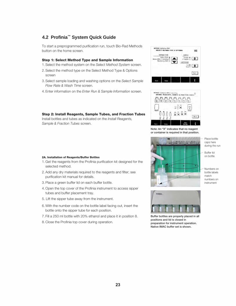
Note: An “X” indicates that no reagentor container is required in that position.
Place bottlecaps hereduring the run
Buffer lid on bottle
Numbers onbottle labelsmatchnumbers oninstrument
Buffer bottles are properly placed in allpositions and lid is closed inpreparation for instrument operation.Native IMAC buffer set is shown.
To start a preprogrammed purification run, touch Bio-Rad Methodsbutton on the home screen.
Step 1: Select Method Type and Sample Information1. Select the method system on the Select Method System screen.
2. Select the method type on the Select Method Type & Optionsscreen
3. Select sample loading and washing options on the Select SampleFlow Rate & Wash Time screen.
4. Enter information on the Enter Run & Sample Information screen.
Step 2: Install Reagents, Sample Tubes, and Fraction TubesInstall bottles and tubes as indicated on the Install Reagents, Sample & Fraction Tubes screen.
2A. Installation of Reagents/Buffer Bottles
1. Get the reagents from the Profinia purification kit designed for theselected method.
2. Add any dry materials required to the reagents and filter; seepurification kit manual for details.
3. Place a green buffer lid on each buffer bottle.
4. Open the top cover of the Profinia instrument to access sipper tubes and buffer placement tray.
5. Lift the sipper tube away from the instrument.
6. With the number code on the bottle label facing out, insert the bottle onto the sipper tube for each position.
7. Fill a 250 ml bottle with 20% ethanol and place it in position 8.
8. Close the Profinia top cover during operation.
24
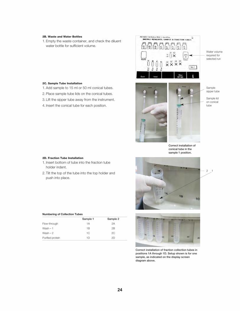
2B. Waste and Water Bottles
1. Empty the waste container, and check the diluentwater bottle for sufficient volume.
2C. Sample Tube Installation
1. Add sample to 15 ml or 50 ml conical tubes.
2. Place sample tube lids on the conical tubes.
3. Lift the sipper tube away from the instrument.
4. Insert the conical tube for each position.
2D. Fraction Tube Installation
1. Insert bottom of tube into the fraction tube holder indent.
2. Tilt the top of the tube into the top holder and push into place.
Numbering of Collection Tubes
Sample 1 Sample 2
Flow-through 1A 2A
Wash – 1 1B 2B
Wash – 2 1C 2C
Purified protein 1D 2D
Correct installation ofconical tube in the sample 1 position.
Water volumerequired forselected run
Correct installation of fraction collection tubes inpositions 1A through 1D. Setup shown is for onesample, as indicated on the display screendiagram above.
2 1
Sample sipper tube
Sample lid on conical tube
25
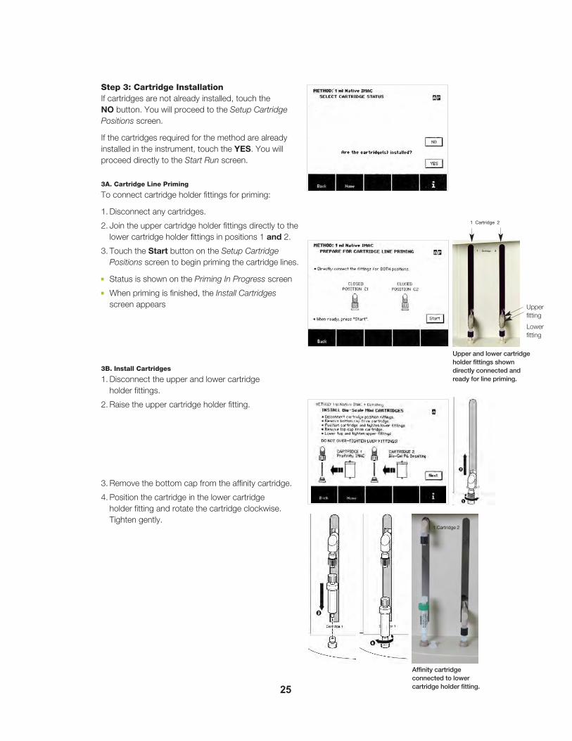
Step 3: Cartridge InstallationIf cartridges are not already installed, touch the NO button. You will proceed to the Setup CartridgePositions screen.
If the cartridges required for the method are already installed in the instrument, touch the YES. You willproceed directly to the Start Run screen.
3A. Cartridge Line Priming
To connect cartridge holder fittings for priming:
1. Disconnect any cartridges.
2. Join the upper cartridge holder fittings directly to thelower cartridge holder fittings in positions 1 and 2.
3. Touch the Start button on the Setup Cartridge Positions screen to begin priming the cartridge lines.
■ Status is shown on the Priming In Progress screen
■ When priming is finished, the Install Cartridgesscreen appears
3B. Install Cartridges
1. Disconnect the upper and lower cartridge holder fittings.
2. Raise the upper cartridge holder fitting.
3. Remove the bottom cap from the affinity cartridge.
4. Position the cartridge in the lower cartridge holder fitting and rotate the cartridge clockwise.Tighten gently.
Upperfitting
Lowerfitting
Upper and lower cartridgeholder fittings showndirectly connected andready for line priming.
Affinity cartridge connected to lowercartridge holder fitting.
1 Cartridge 2
1 Cartridge 2

26
5. Remove the top cap from the cartridge. Move the uppercartridge holder down to the cartridge.
6. Twist the black collar to tighten the upper fitting onto thecartridge until snug.
Note: Do not overtighten fittings. These fittings are designed to seal when turneduntil snug. The cartridge flange may be damaged by overtightening and maythen leak. If leaking occurs, replace the cartridge.
7. Repeat this procedure to install a cartridge in thecartridge 2 position, if required.
8. When cartridge installation is complete, touch the Nextbutton on the Install Cartridges screen. You will proceedto the Start Run screen.
Step 4: Start the Run4A. Start Run Screen
1. To view data in real time on a computer with Profiniasoftware, connect the instrument to a computer, andstart Profinia software before starting the run.
2. Any externally connected reagents or samples should bemanually primed before starting the run.
3. The View Steps button allows you to view detailed stepsof the method.
4B. Run In Progress Screen
The Run In Progress screen displays progress of the run.
■ S1 and S2 arrow marks indicate the approximate time forsample elution
■ Expected elution time is displayed; the sample can becollected at this time
■ The cleaning process is shown in the progress bar as thetime portion after sample elution (S1 and S2)
Cleaning and Run Data
1. When elution is complete, proceed with instrumentcleaning as indicated on the Profinia display.
2. Run data can be downloaded to a USB portable memorydevice through the USB port in the front of the instrument after the cleaning process.
Upper cartridgeholder fittingtightened ontocartridge.
Affinity and desalting cartridges installed inpositions 1 and 2, respectively.
View detailedsteps of themethod
Touch the Start button to start the run
12

Section 5Home Screen OverviewThe LCD touch screen on the front of the instrument is used to control Profinia™ systemfunctions (Figure 5.1). You may use your finger or a stylus to operate the screen. Thehome screen displays date and time information and the UI firmware version number. Theupper right corner of each set-up screen displays various status indicators (see section 3.4).
The toolbar at the bottom of the home screen displays five navigation buttons for the available user options: Bio-Rad Methods, Program Methods, Saved Methods, Data/Utilities,and i (information).
Note: The toolbar remains at the bottom of each system screen; however, button namesand their respective functions will change to reflect the requirements of each screen.
Fig. 5.1. Profinia system home screen.
Home screen toolbar options are:
Bio-Rad Methods — access preprogrammed method templates for affinity chromatography,with or without desalting steps. These methods include native and denaturing IMAC, GSTpurifications, Protein A and G purifications, Profinity eXact purifications, and desalting-onlymethods
Program Methods — customize Bio-Rad method templates by editing the parameters ofmethod steps. A program method can be saved to permanent memory
Saved Methods — access saved program methods. Saved program methods (up to 35 ata time) can be retrieved and viewed by method type or as a single, alphabetical list
Data/Utilities — retrieve run data files, calibrate the system, and run maintenance anddiagnostic functions:
• Data — system memory stores up to three run data files; run data files are in .ofi format. Stored run data files are available for transfer via a USB portable memorydevice (USB flash drive). These run data files can then be imported into the Profiniasoftware program (optional system accessory). Stored run data files that have beentransferred to a USB portable memory device are indicated with an asterisk
27

Warning: Overwritten run data files can no longer be retrieved; the data is permanentlydeleted.
• Calibration — system functions enable calibration of the touch screen, UV monitor,conductivity monitor, pH probe (optional accessory), as well as a pump flow ratecheck and adjustment of peak detection sensitivity (see section 9.2 for details)
• Diagnostics/Maintenance — display firmware version, manual operation, set timeand date, clean sample lines, clean fraction lines, clean buffer lines, system ethanolwash, clean inlet and outlet lines, clean pump check valves, system NaOH wash,select end of sample/reagent detection, and select method temperature functionsare built into the system (see section 9.3 for details)
i — retrieve help information for the current screen; the information button is available inthe toolbar for most system screens. This information is for quick-reference purposes only.For more detailed information, refer to the appropriate section of this instruction manual
28

Section 6Bio-Rad MethodsThe Bio-Rad Methods function of the Profinia™ system is used to select preprogrammedpurification and desalting methods. These methods have been optimized on the Profiniainstrument with Profinia purification kits to provide the highest purity and yield. Purificationkits are available for all Bio-Rad methods that have been preprogrammed in the instrument.When a method type and the associated options are selected, the Profinia screen displaysa method-specific diagram of the system that shows where each cartridge, bottle, and tubeis placed on the instrument. Bottles and cartridges in the purification kits are labeled tomatch the screen diagrams.
The purification procedure used in Bio-Rad methods has the following steps:
1. Select method type and options.
2. Select sample flow rate, cartridge wash time, or incubation time.
3. Enter run and sample information.
4. Install reagents, sample, and fraction tubes.
5. Install cartridge(s).
6. Start run.
7. Monitor run.
8. Clean sample and fraction lines.
9. Select and perform end-of-run options.
10. Shut down system or start a new method.
Instrument Operating Temperature
For Bio-Rad methods that include the desalting step, the instrument operating temperature is critical. Maximum flow rates for the desalting cartridges are lower at 4°Cthan at room temperature. Flow rates over maximum limits compress the bed volume andcause over-pressure errors. Make sure the operating temperature is set to match cold roomor room temperature operating conditions before programming your run. Methods withdesalting steps have longer run times at the cold room setting due to the lower maximumflow rates. The operating temperature setting displays as a status indicator in the upperright corner of the screen. If the cold room operating temperature is selected, “C” appearsonly when methods are selected that include a desalting step. If the room temperature setting is selected, “C” will not display. For affinity-only methods, the temperature setting isirrelevant and will not display. To set the operating temperature:
1. Touch the Data/Utilities button to display the system Utilities screen.
2. Touch the arrow buttons to navigate the list of system utilities; highlight “Select MethodTemperature” then touch Select to display the Select Method Temperature screen(Figure 6.1).
29

Fig. 6.1. Select Method Temperature screen.
3. Touch the arrow button to select “4°C” or “Room Temperature”, then touch the OK button to return to the system Utilities screen.
4. Touch the Home button to return to the system home screen and select the desiredsystem programming option.
Note: Do not change the instrument operating temperature setting to cold room (indicatedby a “C” in the upper-right of the touch screen) when using the cooling accessory. Keep theoperating temperature setting at room temperature unless the entire instrument is operatingin a cold room environment.
30

Figure 6.2 shows the screen sequence when starting a Bio-Rad method.
Fig. 6.2. Screen sequence when starting a Bio-Rad method.
31

To begin a Bio-Rad method purification procedure, touch the Bio-Rad Methods button inthe lower toolbar of the home screen (Figure 6.3). You will proceed to the Select MethodType & Options screen.
Fig. 6.3. System home screen.
6.1 Selecting Method SystemThe Select Method system screen (Figure 6.4) allows you to choose:
• Method system — IMAC, GST, Protein A and G, Profinity eXact methods with or withoutdesalting, or desalting only methods
6.2 Selecting Method Type and OptionsThe Select Method Type & Options screen (Figure 6.5) allows you to choose:
• Method type — The selected affinity method system or desalting only system
• Number of samples — program one or two samples (the desalting-only method canonly be run with one sample)
• Cartridge size — based on sample volume and concentration
• Number of cartridges — available for affinity-only methods when two samples areselected. You may choose to use a single cartridge for both samples or a separate cartridge for each sample
32

Fig. 6.4. Select Method system.
Fig. 6.5. Select Method Type & Options screen.
To select the method type and options:
1. Touch the up and down arrows to select the method type from the list of options displayedon the screen.
Note: The name of the selected method type appears at the top of this screen and all subsequent screens.
2. Touch the arrow button to the right of the Sample list to select “1” or “2” samples.
33

Note: Two samples can be run for all methods except the desalting-only method. Whentwo samples are selected for affinity-only methods, the number of cartridges optionbecomes available. You have the option to use a single cartridge for both samples or aseparate cartridge for each sample. When two samples are selected for affinity with desaltingmethods, both samples are purified using the same cartridge set. Desalting-only methodsare run with one sample that is applied to the cartridge via a sample loop placed in the cartridge 1 position. See section 6.6.5 for details on the installation and use of the desaltingloop.
Note: When purifying two samples through the same cartridge, the method cleans and equilibrates the cartridge prior to loading the second sample.
3. Touch the arrow button to the right of the Cartridge Options list to select the appropriatecartridge size for your method. Select to install “1” or “2” cartridges when this optionbecomes available.
Note: The “1” or “2” cartridge selection option is only available with two-sample, affinity-onlymethods.
When finished setting the method type and options for the run, touch Next to proceed to theSelect Sample parameters screen, or Select Incubation Time screen.
Note: Sample loading flow rate and wash time options are not required with the desalting-only method; you will proceed directly to the Enter Run & Sample Information screen (see Section 6.4).
6.3 Selecting Sample Options
6.3.1 Selecting Sample Flow Rate and Wash Time
Each IMAC, GST, and Protein A and G Bio-Rad method is available with an option toselect from two sample loading flow rates and two cartridge wash times. The SelectSample Flow Rate & Wash Time screen (Figure 6.6) is used to select the sample loadingflow rate and wash time for optimum protein yields and purity (for example, with a highmolecular weight protein, slower flow rates may improve protein binding efficiency and anextended wash time may improve protein purity). Flow rates and wash options can beselected separately for each sample (up to two) used in the run.
Fig. 6.6. Select Sample Flow Rate & Wash Time screen with options displayed for a two-sample method.
34

The Bio-Rad methods function provides two sample loading flow rate options:
• Standard — recommended for normal- to high-expression proteins (<100 kD)
• Low — may improve the yield of low-expression proteins, high MW proteins (>100 kD)or samples containing detergents
The Bio-Rad methods function provides two cartridge wash options:
• Standard — recommended for most purification conditions
• Extended — may improve the purity of product for some sample types
Parameters for each type of method are provided in Table 6.1.
Table 6.1. Sample loading Flow rates and wash volumes by cartridge size for each methodtype option.
Method Type Cartridge Sample Loading Wash-1Size, ml Flow Rate, ml/min Column
Volume (CV)
Standard Low Standard Extended
IMAC, Native 1 2 0.5 6 10
5 10 2.5 6 10
IMAC, Denaturing 1 2 0.5 6 10
5 10 2.5 6 10
GST, 1 1 0.5 12 15Protein A and G
5 5 2.5 12 15
eXact 1 1 – 14 –
5 5 – 10 –
To select the flow rate(s) and wash time(s) for your sample(s):
1. Touch the arrow button to select either the “Standard” or “Low” flow rate for each sample.
2. Touch the arrow button to select either the “Standard” or “Extended” wash option foreach sample.
Note: If a method will be performed with two samples, make flow rate and wash time selections separately for each sample.
When the method options are selected, touch the Next button to proceed to the Enter Run& Sample Information screen. A View Method button will be available in the lower toolbar toview the individual method steps for the sample(s).
6.3.2 Selecting Sample Incubation Time
Each eXact Bio-Rad method is available with an option to select from three different incubationtimes, 0.5 hrs, 2.0 hrs, or 15 hrs (Figure 6.7).
35

Elution of target protein is typically conducted by incubating the resin in the appropriate bufferat room temperature (see Appendix J for buffer formulation details) for 0.5 hrs. Incubationtimes may need to be empirically determined, and for some proteins the incubation time maybe longer. For elution of slower-cleaving proteins, the 2 hour incubation time may be selectedfor room temperature cleavage reactions. However, if elution at 4°C is desired, the 15 hr incubationtime may be selected to ensure complete cleavage. If the Profinia system is operated in acold environment, the method temperature should be set to the 4°C setting the Utilities sectionof the user interface. See Section 9.3.14 for a detailed description of this setting.
During the programmed incubation period, the Stop Incubation button may be used to prematurely terminate the incubation and resume the elution and collection steps of themethod.
Note: If incubation times are needed other than the available options in the Bio-Rad Modethe user can access this method in the Program Mode and program incubation times from0–999 hrs.
When the sample incubation time(s) are selected, touch the Next button to proceed to theEnter Run and Sample information screen.
Fig. 6.7. Select Incubation Time screen.
6.4 Entering Run and Sample InformationThe Enter Run & Sample Information screen (Figure 6.8) allows you to enter identificationinformation for the run. You can enter a run name, lot number information related to thecomponents used in this run, and specific sample details, such as name, volume, and theA280 extinction coefficient. This information is stored with the exportable run data file. Thisscreen also allows access to view the individual method steps and the step parameters viathe View Method button in the lower toolbar.
Note: If you are running a method with two samples, you can enter separate information forboth samples.
36

Fig. 6.8. Enter Run & Sample Information screen.
Note: When two samples are selected for the method, press the View Method button in thelower toolbar to view the method steps and the step parameters for each sample. A ViewSample button is displayed above the arrows in the View Method screen.
The following run-specific information can be entered or selected:
• Username — optional; user-assigned name 3–15 characters in length to document theoperator of the run
• Run name — user-designated file name for the run, up to 30 characters in length
• (External fc) — external fraction collection option; currently not available for operation
• Lot # tracking — optional; lot number information for the buffers, cartridges, and kitsused for the run (“BLANK” indicates no information has been entered). The word “PRESENT” indicates that lot number information was entered. The lot number information remains in memory as long as the instrument power remains on. Whencycling the power, the lot number information reverts to “BLANK”
The following sample-specific information can be entered or selected:
• Sample name — optional; user-assigned name for the sample, up to 15 characters inlength (“UNTITLED” indicates no information has been entered). If you have chosen toperform a run with two samples, you can assign a name for each sample
• Volume — user-entered sample volume between 2 ml and 50 ml. If you have chosento perform a run with two samples, a volume must be entered for each sample. If the sample volume is greater than 50 ml, see section 7 for information on program methods.If the sample volume is less than 2 ml, diluting the sample with 1x lysis buffer to a totalvolume of >10 ml is recommended to obtain optimum yield
Note: When the desalting-only method is selected, the sample volume is fixed at 2 ml for the10 ml cartridge and 10 ml for the 50 ml cartridge. The sample volume is 20% of the cartridgevolume, the optimized volume for buffer exchange.
37

• A280 of 1 mg/ml — extinction coefficient for the protein expressed as the absorbance ofa 1 mg/ml solution of the protein of interest at 280 nm for a 1 cm UV pathlength. Thedefault value for this parameter is 1.00. An extinction coefficient can be assigned foreach sample. This value is used to calculate the estimated total protein and proteinconcentration at the end of the run. An extinction coefficient converts absorbance units(AU or OD) to concentration units (mg/ml). For example, if a protein has an AU of 1.38,and an extinction coefficient of 1.25 AU/mg/ml, the concentration of that protein solutionis calculated as 1.38 AU/1.25 AU/mg/ml = 1.1 mg/ml. The Profinia firmware uses thisalgorithm to calculate protein concentration and yield from the absorbance units underthe purified peak.
Note: If you measure the absorbance of your protein with a short-pathlength cuvette, youmust multiply the absorbance value to normalize to 1 cm. For example, the absorbancemeasured in a 2 mm cuvette must be multiplied by 5. This value is then entered for A280 of1 mg/ml.
• Home — returns to the home screen. All entered run and sample information, exceptlot number tracking information, will be cleared when you select the Home button. Theentered lot number tracking information remains in temporary memory as long asinstrument power is on. When cycling power, lot number tracking information defaults to“BLANK”
6.4.1 Adding or Editing Run and Sample Information
To add or edit sample and run information:
1. Touch the arrow buttons to the right of the information text box to scroll through the listof options and highlight the parameter for which you’d like to add information.
2. Touch the Edit button to access the alphanumeric or numeric keypad. The appropriatekeypad displays.
3. Enter or edit information for the selected parameter in the text line at the top of thescreen.
Note: If values entered exceed the system-set limits, the value limits appear immediatelybelow the text line of the numeric keypad and the system overrides the entered value withthe maximum or minimum value allowed.
4. Touch OK to accept all changes or Cancel to delete any entered data and return to theEnter Run & Sample Information screen.
5. Repeat this process for all information parameters. For details on entering lot numbertracking, see section 6.4.2 below.
Note: Touch the Clear All button to delete the text or data entered into the text line. Thedefault “UNTITLED” text can be cleared with any keystroke.
6.4.2 Adding Lot Number Tracking Information
To add lot number information for any of the reagents or components used in your method:
1. Use the arrow buttons to the right of the information text box to scroll through the list ofoptions and highlight “Lot # Tracking”.
2. Touch the Edit button. You will proceed to the Edit Lot Number Information screen(Figure 6.9).
38

Fig. 6.9. Edit Lot Number Information screen.
3. Touch the arrow buttons to the right of the lot number information text box to scrollthrough the list of kit information (buffers, solutions, and cartridges) relevant to the run.Highlight the item for which you want to add lot number information.
4. Touch the Edit button to retrieve the alphanumeric keypad.
5. Enter desired information into the keypad text line.
6. Touch OK to save input data and return to the Edit Lot Number Information screen, orCancel to return to the Edit Lot Number Information screen without saving changes.
7. Repeat this process for each item that requires lot number information.
8. Touch Clear All to delete all information added, or OK to accept changes and return tothe Enter Run & Sample Information screen.
When all run and sample information has been satisfactorily updated, touch the Next button.You will proceed to the Install Reagents, Sample & Fraction Tubes screen.
6.5 Installing Reagents, Sample Tubes, and Fraction TubesThe Install Reagents, Sample & Fraction Tube screen (Figure 6.10) displays a diagramshowing where buffer, diluent, sample, and waste containers should be placed in theProfinia instrument (cartridge installation is described in Section 6.6). This diagram is specific to the method type and options selected for the run. The volumes indicatedfor the buffer and water bottles are the minimum volumes required. Volumes indicated forthe fractions are those that will be delivered to the fraction tubes. An “X” in any position indicates that no reagent or container is required in that position.
Note: If the reagent volumes exceed the container capacity, a larger container can be connected to the instrument externally. When reagents are connected externally make sureto prime the lines manually immediately prior to starting the run. The manual priming functionis available in the Start Run screen.
39

Fig. 6.10. Install Reagents, Sample & Fraction Tubes screen (left) with arrows demonstrating the correlationbetween the diagram and placement of reagents in the Profinia instrument (right).
The installation screen diagram displays:
• Buffer bottles — eight buffer bottle positions indicated by labels B1 through B8 on thetouch screen (top of the screen) and 1 through 8 on the instrument (upper tray). Thetouch-screen diagram also displays the minimum buffer volumes required for the selectedmethod; an “X” indicates no reagent is required at that location
Note: Profinia purification kit reagent bottles are labeled with the instrument buffer positionnumbers, which are also displayed on the instrument Install Reagents, Sample & FractionTubes screen.
• Waste bottle — left side of the touch-screen diagram and positioned at the lower left ofthe instrument. On the touch screen, the waste bottle is displayed without a volume asa reminder to make sure the waste bottle is emptied frequently
• Diluent (water) bottle — right side of the touch-screen diagram and positioned at thelower right of the instrument. On the touch screen, the diagram is labeled with the minimum volume of water required for the selected method run
• Sample tubes — indicated by S1 and S2 labels on the touch screen, the sample tubesare placed beneath the buffer bottles toward the right of the instrument. The touchscreen displays one or two sample tubes with the sample volumes, depending on thenumber of samples and sample volumes that have been entered by the user on theEnter Run & Sample Information screen
Note: Each run primes the sample line(s) with about 1 ml of sample. To ensure that theentered sample volume is loaded onto the cartridge, filling the sample tubes with 1 ml morethan the entered volume is recommended. If the exact entered volume is added to the sample tube, the end of sample detection, if activated, applies the complete sample to thesystem. In this case, the total amount of sample added to the cartridge will be approximately0.5 ml less than the entered volume. To maximize protein yields, 10 ml is the minimum recommended sample load.
40

• Fraction collection tubes — indicated on the touch screen by a set of four tubes onthe left labeled 1A through 1D for sample 1 collection, and four tubes on the rightlabeled 2A through 2D for sample 2 collection. Fraction tubes are placed at the bottomof the instrument. Each fraction tube shows the volume that will be collected in the tube.Only the required fraction tubes are represented on the Install Reagent, Sample &Fraction Tubes screen. Before beginning your run, make sure the fraction tube capacitiesmatch the volumes indicated on the screen
Note: The fraction positions are numbered 1A through 1D from left to right, and 2A through2D are ordered right to left. This places the purified protein in the center two positions foreasiest access and for use with the cooling accessory.
• View Details — lower toolbar button; proceeds to a screen that displays the name foreach of the components shown in the system setup screen (Figure 6.11). Touch OK toreturn to the Install Reagents, Sample & Fraction Tubes screen
Fig. 6.11. Review Buffer & Fraction Details screen displayed when the View Details button is selected.
6.5.1 Loading Buffers
The Bio-Rad Methods function of the Profinia system is designed to operate with Profiniapurification kits that contain concentrated buffers and cartridges for each preprogrammedmethod type. To prepare reagents for the method run:
Note: See Appendix I and J for recommended reagents for the Protein A and G andProfinity eXact methods.
1. Remove reagents from the Profinia purification kit designed for your selected methodtype (see section 10).
2. Prepare reagents as specified in the purification kit instruction manual. Some of thebuffers require the addition of dry reagents followed by filtration, such as those fordenaturing IMAC and GST methods.
3. When reagents are ready for loading into the Profinia instrument, place a buffer lid oneach buffer bottle (Figure 6.12).
41

Fig. 6.12. Replace buffer caps with buffer lids before installation.
4. Open the lid on the Profinia instrument to access buffer sipper tubes and the placementtray.
5. In the position where the buffer bottle is being installed, lift the sipper tube away fromthe instrument.
6. With the number code on the bottle label facing out and graduated marks visible, insertthe sipper tube in the bottle (Figure 6.13).
Fig. 6.13. Loading buffer bottle onto sipper tube in buffer position 1.
42

Important: It is important to orient the buffer bottles properly in the instrument; the graduatedmarks on the buffer bottles are used to determine how much buffer is available for thepurification run, so you must be able to see them (Figure 6.14).
7. Close the Profinia lid to protect the buffer bottles and sipper tubes during operation(Figure 6.15).
Fig. 6.14. Proper placement of buffer bottles in the instrument, with orientation marks visible; buffer capsare stored above respective bottle positions.
Fig. 6.15. Buffer bottles properly placed in all positions and lid closed in preparation for instrument operation. The native IMAC plus desalting buffer setup is shown.
43
Bufferbottle cap
Buffer sipper tube
Buffer positionnumber
Bufferbottle lid
Bufferbottle graduatedmarks

Note: Some kits do not require a reagent bottle in every position. If a position does notrequire a bottle (indicated by an “X” on the installation screen), leave that position empty, orplace a bottle with water in that position.
6.5.2 Installing Sample Tubes
The sample loading area is on the front right side of the instrument (Figure 6.16).
Fig. 6.16. Instrument sample loading area.
To load sample(s):
1. Add the required amount of sample to the sample tubes as indicated on the touchscreen. If you are running more than one sample, place sample 1 in the sample 1 position,and sample 2 in the sample 2 position (S1 and S2 on the installation screen, respectively).
Warning: If end of sample detection has been disabled, enter a sample volume approximately0.5 ml less than the actual sample volume to prevent air from entering the instrument (see Section 9.3.12 for more information).
2. Place sample lids on the sample tubes.
3. For each sample tube position, lift the sipper tube away from the instrument and insertthe sample tube into the sample sipper tube. If only one sample is needed (S1), thesecond sample position (S2) can remain empty, or place a tube with water in the S2position.
44
Sample lid

6.5.3 Installing Fraction Collection Tubes
The fraction collection area is at the bottom of the Profinia instrument (Figure 6.17).Fractions are collected into standard laboratory conical tubes. The Profinia instrument canaccommodate both 15 ml and 50 ml conical tubes (see Section 1.4 for conical tube recommendations). When one sample has been installed for a purification run, place fraction collection tubes as indicated in the system installation screen in positions 1Athrough 1D. For two-sample purification runs, place fraction collection tubes in positions 1Athrough 1D and 2A through 2D (the number of tubes is method-dependent; not all methodsrequire four tubes per sample).
Operations performed or product obtained by position:
• 1A and 2A: flow-through
• 1B and 2B: wash 1
• 1C and 2C: wash 2
• 1D and 2D: purified protein
Fig. 6.17. Fraction tube collection area with tube positions marked 1A through 1D (for runs performed withone sample) and 2A through 2D (for runs performed with two samples).
To install the fraction collection tubes:
1. For each fraction collection position, insert the bottom of a conical tube into the indentedspot on the bottom of the fraction collection area.
2. Push the top of the conical tube into the top tube holder (Figure 6.18).
3. Insert the tubes for each position required in your purification run.
45

Fig. 6.18. Installation of a tube into fraction tube position 1D.
When all fraction tubes required in the run have been installed, touch the Next button tobegin the cartridge installation procedure.
6.6 Installing CartridgesThe cartridge installation process includes preparatory steps such as priming the systemcartridge lines to prevent introduction of air bubbles into the cartridge. The cartridge installation routine is carried out through four consecutive screens:
• Select Cartridge Status — includes the option to bypass the installation procedure when cartridges are already installed (for example, from a previous run)
• Setup Cartridge Positions for Priming — directs connection of the cartridge 1 and 2position fittings
• Priming in Progress — displays the priming time progress bar
• Install Cartridges — displays the required cartridges and their respective positions
Warning: When the desalting-only method is selected DO NOT fill the sample loop withsample until the sample loop and cartridge installation is completed. Inject the sampleimmediately prior to starting the run. (See Section 6.6.5 for sample loop installation instructions.)
6.6.1 Select Cartridge Status
Two options are available on the Prepare for Cartridge Installation screen (Figure 6.19):
• No — cartridges are not installed and the system cartridge lines need to be primed;touch the No button to proceed to the Prepare for Cartridge Line Priming screen
• Yes — cartridges are already installed and priming is not needed; touch the Yes button to bypass priming and proceed directly to the Start Run screen (Section 6.7)
46

Fig. 6.19. Select cartridge status screen.
6.6.2 Setting Up Cartridge Positions for Priming
Follow the instructions on the screen to prepare both cartridge positions for priming. Bothpositions need to be closed as indicated on the screen (Figure 6.20).
Note: Make sure the luer fittings are connected properly. Do not overtighten.Overtightening can lead to stripped threads which, over time, can lead to leaking.
When both cartridge positions are closed, touch the Start button to begin the priming process.
Fig. 6.20. Prepare for Cartridge Line Priming screen showing instructions for connecting cartridge positions (left); upper and lower fittings connected (closed) for both cartridge positions (right).
47

6.6.3 Priming the Cartridge Lines
The Priming in Progress screen (Figure 6.21) displays a progress bar that indicates thepercentage of priming time completed. Priming is completed in 30 seconds.
Fig. 6.21. Priming in Progress screen.
If the system leaks from the cartridge positions during priming, the fittings are not properly connected. To correct this problem:
1. Touch the Pause button in the lower right corner of the screen to stop the priming procedure.
2. If necessary, reconnect the upper and lower cartridge fittings for each position (1 and 2).
3. Touch Start to resume the priming procedure, or touch the Back button to return to theprevious screen and restart the priming process.
When priming is finished, you will automatically proceed to the Install Cartridges screen.
6.6.4 Installing Cartridges
The Install Bio-Scale Mini Cartridges screen (Figure 6.22) shows the required Bio-Scale™
Mini cartridges and their respective positions. It also displays instructions for installing thecartridges into the Profinia system.
48
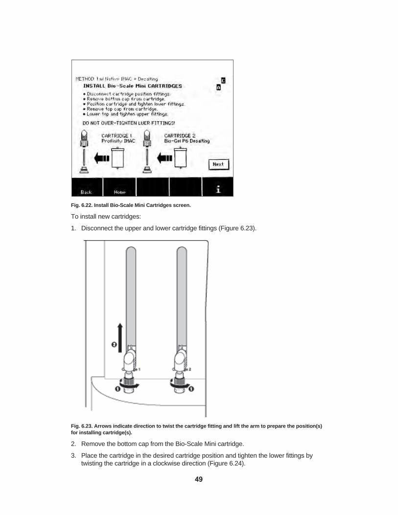
Fig. 6.22. Install Bio-Scale Mini Cartridges screen.
To install new cartridges:
1. Disconnect the upper and lower cartridge fittings (Figure 6.23).
Fig. 6.23. Arrows indicate direction to twist the cartridge fitting and lift the arm to prepare the position(s)for installing cartridge(s).
2. Remove the bottom cap from the Bio-Scale Mini cartridge.
3. Place the cartridge in the desired cartridge position and tighten the lower fittings bytwisting the cartridge in a clockwise direction (Figure 6.24).
49

Fig. 6.24. Inserting the cartridge into the cartridge 1 position; twist the cartridge in a clockwise directionas indicated by the arrow to fit the bottom part of the cartridge into position.
4. Remove the top cap from the cartridge.
5. Lower the cartridge arm and twist the black collar clockwise to tighten the upper fittingand connect it to the cartridge (Figure 6.25). Do not use excessive force.
50

Fig. 6.25. Completing the cartridge installation procedure.
6. Repeat this procedure to install a Bio-Scale Mini cartridge into the cartridge 2 position.
Note: If no cartridge will be placed in the cartridge 2 position, keep the system cartridge fittings in the closed position (Figure 6.26).
Note: Do not overtighten fittings. Luer lock fittings are designed to seal when turned tosnug. The cartridge flange may be damaged by overtightening and cause leakage. In thiscase, replace the cartridge.
51

Fig. 6.26. Lower fitting tightened into place (left) and upper cartridge fitting tightened into place (right);cartridge 2 position remains closed.
When cartridge installation is complete, touch the Next button in the lower right corner ofthe screen. You will proceed to the Start Run screen.
6.6.5 Installing the Sample Loop (Desalting-Only Methods)
Warning: When the desalting-only method is selected, DO NOT fill the sample loop withsample until the sample loop and cartridge installation is completed. Inject the sampleimmediately prior to starting the run.
Sample loading for a desalting-only method is achieved via a sample loop. Installation isdirected by the Install Bio-Scale Mini Cartridges screen (Figure 6.27). The desalting sampleloop accessory connects to the instrument in the cartridge 1 position and the desalting cartridge in the cartridge 2 position (Figure 6.29).
52

Fig. 6.27. Install Bio-Scale Mini Cartridges screen showing sample loop installation in the cartridge 1position.
To connect and fill the desalting loop:
1. Insert the male luer fitting from cartridge holder 1 into the top female luer fitting of the 3-way stopcock. Ensure that the second female luer fitting of the 3-way stopcock is facing out so the syringe may be easily inserted.
2. Connect the male luer of the end of the desalting loop to the female luer fitting of cartridge holder 1.
3. Install the desalting cartridge in the cartridge 2 position. Touch the Next button to proceedto the Start Run screen (Figure 6.28).
Fig. 6.28. Start Run screen directs application of the sample to the sample loop (desalting-only method).
53

4. To apply sample, fill the syringe and insert it into the open female luer of the 3-waystopcock. Turn the 3 way stopcock lever up (toward the top inlet fitting), and inject thesample into the loop.
5. Return the 3-way stopcock lever to the middle position, facing toward the syringe. Thedesalting loop is now filled with sample and ready for the desalting method to begin.
Fig. 6.29. Sample loop installed in the cartridge 1 position.
Note: Determine the appropriate combination of desalting loop and desalting cartridge forthe protein sample volume to be applied. For a 2 ml sample, choose the 2 ml desalting loopand the 10 ml desalting cartridge. For a 10 ml sample, choose the 10 ml desalting loop andthe 50 ml desalting cartridge. Application of a sample volume smaller than the desaltingloop volume is not recommended, since it will result in increased dilution of the sample andreduced desalting resolution, desalting resolution. If desired, small volume samples can bediluted to 2 or 10 ml for buffer exchange applications.
6.7 Starting the Run The Start Run screen (Figure 6.30) displays a summary of the sample information. Areminder prompts you to connect the instrument to a computer running Profinia software ifyou would like to view the chromatogram in real time (see section 12 for more informationon Profinia software). The Profinia system does not require software to operate the instrument;current data points appear on the run screen.
The lower toolbar contains buttons for viewing the methods steps and for optional manualpriming of any extra tubing attached to the sample, buffer, diluent, or waste lines to accommodate larger containers in these instrument ports (see section 11.2 for details).
54

Fig. 6.30. Start Run screen.
6.7.1 Viewing Steps
Touch the View Steps button (available on the Start Run screen at any point during the run)to display the View Method Steps screen (Figure 6.31). During a run, the step that is currently in progress is highlighted.
The following columns of information are displayed on the View Method Steps screen:
• Step — numbered list of the primary steps that will be performed in the run
• Name — brief description of the operation associated with the step
• Conc. — buffer position in the instrument and buffer concentration (the instrumentdilutes concentrated buffers)
• ml/min — flow rate displayed in ml/min
• CV — column volume based on the cartridge size (for example, for a 1 ml IMAC cartridge,2 CV = 2 ml)
• Min — duration of each step in minutes
During a run, the step currently in progress is highlighted.
55

Fig. 6.31. View Method Steps screen.
6.7.2 Viewing Real-Time Data with Profinia Software
The Profinia system does not require software and a computer to operate the instrument;individual data points are displayed on the run screen. However, with Profinia software(optional) installed on a computer and connected directly to the instrument through theUSB port on the back of the instrument (Figure 6.32), the run chromatogram can beviewed in real time. The USB cable for instrument-to-computer connection is included withthe software.
Note: The front USB port does not output real-time data. The front port is used to downloadthe run data files onto a portable memory device when the run is completed, or from systemmemory using the Export Data function in the Data/Utilities menu (section 9.1).
To collect real-time data:
1. Connect the USB cable to the USB port on the back of the instrument and to the computer.
Fig. 6.32. USB cable connected to the Profinia instrument.
56

2. Open Profinia software on your computer by double-clicking on the desktop Profiniasoftware icon. Look for the “Waiting for data” message in the lower left corner of thesoftware screen. This indicates the instrument is communicating with the software anda run can be started (Figure 6.33).
Fig. 6.33. “Waiting for data” message on the bottom of the Profinia software screen.
At this point, the run can be started and the chromatogram appears on the computerscreen.
Important: The real-time USB data connection cannot be established once the Start buttonhas been touched and a run has been started. However, the run data file can be exportedto a USB portable memory device and transferred to Profinia software after the completionof the run.
6.7.3 Clearing System Memory to Start the Run
To start your purification run:
Touch the Start button. The Preparing Data Memory Storage screen displays a progressbar indicating temporary memory data clearance. The system can store up to three rundata files in memory. An “M” status indicator displayed in the upper right corner of thescreen indicates none of the run data files stored in system memory have been transferred. If system memory is full (indicated by “F” in the status position), the oldesttransferred or stored data file will be overwritten with the new file when a purification run isstarted.
Fig. 6.34. Touch Start on the Start Run screen to begin a purification run.
57
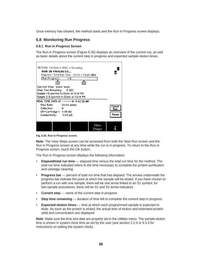
Once memory has cleared, the method starts and the Run in Progress screen displays.
6.8 Monitoring Run Progress
6.8.1 Run in Progress Screen
The Run in Progress screen (Figure 6.35) displays an overview of the current run, as wellas basic details about the current step in progress and expected sample elution times.
Fig. 6.35. Run in Progress screen.
Note: The View Steps screen can be accessed from both the Start Run screen and theRun in Progress screen at any time while the run is in progress. To return to the Run inProgress screen, touch the OK button.
The Run in Progress screen displays the following information:
• Elapsed/total run time — elapsed time versus the total run time for the method. Thetotal run time indicated refers to the time necessary to complete the protein purificationand cartridge cleaning
• Progress bar — percent of total run time that has elapsed. The arrows underneath theprogress bar indicate the point at which the sample will be eluted. If you have chosen toperform a run with one sample, there will be one arrow linked to an S1 symbol; for two-sample procedures, there will be S1 and S2 arrow indicators
• Current step — name of the current step in progress
• Step time remaining — duration of time left to complete the current step in progress
• Expected elution times — time at which each programmed sample is expected toelute. As soon as the protein is eluted, the actual time of elution and estimated proteinyield and concentration are displayed
Note: Make sure the time and date are properly set in the Utilities menu. The sample elutiontime is shown in system clock time as set by the user (see section 2.2.3 or 9.3.3 for instructions on setting the system clock).
58

The lower part of the Run in Progress screen shows the real-time data:
• Real-time data at — system clock time. The date and time setting is available in theData/Utilities section accessed from the home screen
• Flow rate — flow rate of the current step (displayed in ml/min)
• Collection — in which fraction tube the system is diverting output from the current step
• UV cartridge — appears as UV cartridge 1 when fluid goes through cartridge 1, andswitches to UV cartridge 2 when fluid goes through cartridge 2, displayed inabsorbance units (AU)
Note: Automatic peak detection is activated for specific elution steps. When Profiniafirmware is actively looking for the peak, a light bulb icon is displayed immediately in front ofthe UV cartridge line. For details on automatic peak detection, see section 6.8.2.
• Conductivity — value is given in mS/cm
• pH — value appears when a pH monitor (optional) is connected to the Profinia system
6.8.2 Peak Detection
Affinity and desalting protein peaks are identified using an automatic peak detection algorithmthat is active during elution steps on the Profinia instrument. In addition to automatic peakdetection, the option to manually detect and divert the protein peak is also available duringaffinity and desalting elution step(s). When manual peak detection is available during affinityand desalting elution steps, the manual peak detection button displays on the Run inProgress screen. Once a peak is detected either automatically or manually and the nextelution step is started, the manual peak divert button displays. For the vast majority of proteins, automatic peak detection is the preferred and most robust route for peak collection.
Automatic Peak Detection
Automatic peak detection is an essential feature for identification, diversion, and collection ofthe eluted protein peaks on the Profinia instrument. Automatic peak detection includes several parameters that may be changed from the default settings, depending on themethod:
• Peak detect delay — at the start of the elution step, the automatic peak detection algorithm is activated after a set time delay. The programmed default setting for peakdetect delay is based on the fluidics of the Profinia instrument and is optimized for Bio-Rad methods. After the specified peak detect delay, the Profinia instrument startsactively monitoring for the expected affinity or desalting peak, and a light bulb icon displays on the screen immediately in front of the UV cartridge line. Following peakdetection, the method proceeds to the next step and the light bulb icon disappears. Thepeak detect delay parameter is intended to prevent premature activation of the automaticpeak detection algorithm, which could be caused by late eluting contaminants on wash 2steps.
• Max peak volume — maximum volume the system pumps before overriding automaticpeak detection. Once this volume is reached and a peak was not detected, the methodproceeds to the next step. The programmed default setting for max peak volume isbased on the fluidics of the Profinia instrument and is optimized for Bio-Rad methods.The max peak volume parameter is intended to prevent loss of sample in the event theautomatic peak detection algorithm does not recognize a peak during the specified timewindow
59

Note: The peak detect delay and max peak volume parameters can only be edited in theprogram methods mode (see section 7.3.1).
• Peak detection sensitivity — settings range between 0.1 (most sensitive) and 10(least sensitive); the default setting is 1. Peak detection sensitivity is a global settingaccessible in the Data/Utilities menu for both Bio-Rad methods and program methodsmodes. The peak detection sensitivity parameter programs the Profinia instrument toadjust the automatic peak detection algorithm to various peak shapes and sizes in theevent the default setting does not recognize a peak during the specified time window. Ingeneral, use lower numbers (more sensitive) if a small protein peak is expected.
Note: Using more sensitive settings for peak detection may lead to activation of automaticpeak detection from small UV deviations not associated with the protein peak.
Manual Peak Detection
In addition to automatic peak detection, the instrument provides the option to manuallydetect and divert the protein peak during affinity and desalting elution steps. Manual peakdetection can be used for:
• Purifications where the target protein is in a very low concentration (<1 mg/ml) or has avery low extinction coefficient. Cold room purification and using program methods withthe protein elution at a flow rate lower than 0.5 ml/min may generate UV trace slopesnot steep enough to be detected by the Profinia peak detection algorithm. If these typesof sample and running conditions are typical, then it is recommended to adjust the peakdetection setting to the highest sensitivity: 0.1. However, the Bio-Rad methods defaultvalue for the max peak volume is intended as a safety for cases where the peak is notautomatically detected, for example, for very low expression proteins. When this valueis reached the method will advance to the next step to ensure that the region where theprotein is eluting will be collected
• Overriding the automatic peak detection to collect the highest possible protein concentration by manually selecting the peak section with the highest absorbance values.To override the automatic peak detection, set the peak detect delay time and max peakvolume to values well beyond the point the peak is expected to elute. Editing these values is possible in program methods mode only (see section 7.3.1 for more details).
The manual peak detect and manual peak divert buttons will display on the screen duringthe appropriate protein elution steps only.
Using manual peak detect:
When the protein peak starts to elute, touch the Manual Peak Detect button to immediately advance to the next step without waiting for automatic peak detection or themax peak volume setting.
Using manual peak divert:
You have the option to minimize the volume in which the purified protein is collected.Diverting fraction collection before the peak trailing ends decreases the total yield andincreases protein concentration.
60

Fig. 6.36. Touch the Manual Peak Divert button at the step in the run indicated by the arrow to optimizeconcentration of the eluted protein.
When the protein peak has eluted (Figure 6.36), you can touch the Manual Peak Divert button(Figure 6.37) to automatically advance to the next step without waiting for the completion ofthat step.
Fig. 6.37. Run in Progress screen with Manual Peak Divert button displayed.
6.8.3 Collecting the Purified Sample
The purified sample is collected in fraction tube position 1D (sample 1) or 2D (sample 2).When the purified protein is collected, the Run in Progress screen displays the actual elution times and tubes 1D and 2D can be removed. After the target protein has eluted, theProfinia system automatically continues to run the cartridge cleaning and storage proceduresand purify the second sample if selected.
61

6.8.4 Canceling or Pausing a Run
To cancel the run (when you cancel a run, you proceed to the Prepare System to CleanLines screen):
1. Touch the Cancel Run button in the lower right of the screen. A confirmation screenappears. The run continues until the cancel confirmation is made.
2. Touch OK to terminate the run, or Cancel to return to the Run in Progress screen andcontinue the run.
To pause the run:
1. Touch the Pause button in the lower right of the screen to proceed to the Pause screen.
2. To resume the run, touch the Run button.
3. To cancel the run, touch the Cancel button.
6.8.5 Completing the Run
Run results display as soon as the end-of-run cleaning procedures are completed.
6.9 Preparing System for End-of-Run CleaningSystem cleaning is an automatic feature that occurs upon completion of each method runand is required to prevent cross-contamination between runs and to maintain the system inoptimum condition. The two sample inlet lines and the fraction line valve (all eight fractionlines) are cleaned as part of the end-of-run cleaning process. The pump seals are alsowashed as the final step in this process and the internal system lines are stored with 20%ethanol from buffer position 8 (Figure 6.38).
Fig. 6.38. Prepare System to Clean Lines screen.
6.9.1 Preparing for Line Cleaning
To prepare the system for end-of-run cleaning:
1. Remove all sample tubes from the instrument.
62

2. Place tubes containing 10 ml of deionized water in both sample 1 and sample 2 positions;place water in both sample positions even if only one sample was used in the run.
3. Fill a buffer bottle with 20% ethanol and place it in buffer position 8.
4. Remove all fraction collection tubes from the instrument.
5. Place the cleaning tray (provided with the instrument) in the fraction collection area.
6. Touch the Start button to begin the cleaning procedure.
You will proceed to the System Cleaning in Progress screen.
6.9.2 System Cleaning in Progress
When system cleaning starts, the System Cleaning in Progress screen (Figure 6.39) displaysthe four system cleaning procedures: Clean Sample Lines, Clean Fraction Lines, CleanBuffer Lines, and System EtOH Wash. The cleaning steps that will be performed after a runis completed are indicated by darkened circles. A checkmark adjacent to a darkened circleindicates the cleaning step has been completed. When the cleaning process is completed,you will proceed to the Run Completed screen where the run results are displayed.
Fig. 6.39. System Cleaning in Progress screen showing fraction line cleaning is in progress. The actualcleaning step, indicated by a number code and brief description, is displayed below the progress bar.
Note: The Clean Buffer Lines and System EtOH Wash options are available as short-termor long-term cleaning methods, respectively, in the Run Completed screen. All cleaningoptions are also accessible via the Data/Utilities menu accessible from the home screen.
6.10 Performing End-of-Run ProceduresThe Run Completed screen (Figure 6.40) is displayed upon completion of all purification runsteps, including system cleaning. Run details for each sample purified are displayed in therun data table. The total estimated protein (yield) and protein concentration have been calculated and are displayed for each sample.
63

Fig. 6.40. Run Completed screen.
6.10.1 Exporting Data to a Computer
The run data file can be transferred to a portable memory device as an .ofi file, which can beimported into Profinia software (optional) for viewing data in tabular form or in a chromatogram.If Profinia software has not been purchased, the data file can be viewed in any compatiblespreadsheet software (for example, Microsoft Excel). To export the run data file:
1. Insert a USB portable memory device into the USB port directly below the touch screen.The Export Data button is initially displayed with an “X” across it, indicating that the button is not yet functional. As soon as the system recognizes the portable memorydevice, the “X” disappears and the Export Data button is available. The time requiredfor recognition depends on the portable device used and can take up to 15 sec. (Seetroubleshooting in Appendix C if the memory device is not recognized).
2. Touch the Export Data button in the lower right corner of the End of Run screen. Aprogress bar displays indicating that the transfer is in progress; typical transfer timesare approximately 60 sec. The actual transfer time depends on the amount of data inthe run data file and the portable memory device.
Upon completion of data export, you will automatically return to the Run Completed screen.
6.10.2 Performing Final Run Procedures
The toolbar at the bottom of the Run Completed screen displays final steps to shut down thesystem or prepare for a new run. Choose one of the following options:
• Re-Run Method — immediately begin a new sample run with the same method
• Run New Method — immediately begin another purification run using a differentmethod type, or new buffers for the run that was just performed
• Short-Term Wash — if the system will not be used again on the same day, the bufferlines and valves should be rinsed with water
• Long-Term Wash — if the system will not be used in the next 2 days, it should berinsed with water and ethanol or other sanitizer to maintain optimum mechanical performance and prevent bacterial growth
64

Re-Running a Method
To repeat the method just performed with the same buffers, touch the Re-Run Method button in the toolbar at the bottom of the End of Run screen. You will return to the EnterRun & Sample Information screen to repeat the Bio-Rad methods set-up and run process.
Running a New Method
Two options are available when the Run New Method button is selected upon completionof a run: select a new method utilizing the same buffers, or select a new method thatrequires a different buffer set. When the same buffers are used you will proceed directly tothe Select Method Type & Options screen to follow the procedures for starting a new run.When different buffers are required, you can rinse the buffer lines prior to proceeding to thehome screen.
To run a new method:
1. Touch the Run New Method button in the toolbar at the bottom of the End of Runscreen. You will proceed to the Prepare System to Clean Lines screen (Figure 6.41).
Fig. 6.41. Prepare System to Clean Lines screen displays when running a new method to clean bufferlines if a new buffer set is being used.
2. Touch the Home button in the toolbar if a new method with the same buffers will be run.You will proceed directly to the home screen.
3. Touch the Back button to return to the End of Run screen to select a different option.
4. To select the wash buffer line cleaning procedure, follow the onscreen directions andtouch the Start button to begin the cleaning procedure. When the buffer line cleaningprocedure is complete, you will automatically proceed to the Select Method Type &Options screen.
Cleaning the System for Short-Term Storage
If the Profinia system will not be used again on the same day, performing the short-termwash procedure (buffer lines and pump seal wash) to maintain the system in optimum condition is recommended. To perform a wash for short-term storage, touch the Short-TermWash button in the toolbar at the bottom of the End of Run screen. You will proceed to thePrepare System to Clean Lines, short-term wash screen (Figure 6.42).
65

Fig. 6.42. Prepare System to Clean Lines, short-term wash selected screen.
To prepare the system for the short-term wash, follow the onscreen instructions:
1. Place bottles with deionized water in buffer positions 1 through 7.
2. Fill a buffer bottle with 20% ethanol and place it in buffer position 8.
3. Remove all cartridges and directly connect the upper and lower cartridge fittings.
4. Place the Profinia cleaning tray in the fraction collection port.
5. Touch the Start button to begin short-term storage cleaning; the cleaning progressscreen displays. Immediately below the progress bar, the current line cleaning is indicated.
When the cleaning process is completed, you will automatically return to the home screen.
Cleaning the System for Long-Term Storage
If the Profinia system will not be used within the next 2 days, it should be rinsed with waterand 20% ethanol or other sanitizer to maintain optimum mechanical performance and prevent bacterial growth. To perform a long-term storage wash, touch the Long-Term Washbutton in the toolbar. You will proceed to the Prepare System to Clean Lines, long-term washscreen (Figure 6.43).
66

Fig. 6.43. Prepare System to Clean Lines, long-term wash screen.
To prepare the system for the long-term wash:
1. Place bottles of deionized water, 20% ethanol, or other sanitizer in buffer positions 1through 7.
2. Place a bottle with 20% ethanol (or other sanitizer) in buffer position 8.
3. Place tubes containing 10 ml of deionized water, 20% ethanol, or other sanitizer in bothsample 1 and sample 2 positions.
4. Remove all cartridges and directly connect the upper and lower cartridge fittings.
5. Place the cleaning tray in the fraction collection area.
6. Touch the Start button to begin long-term storage cleaning; the cleaning progressscreen displays. Immediately below the progress bar, the current line cleaning is indicated.
When long-term cleaning is finished, a message on the touch screen appears prompting youto cap all system lines and turn the instrument off.
Important: When the Profinia system is used in a cold environment, it is best to leaveinstrument power on when not in use; the slight amount of heat generated helps controlcondensation. The UV lamp automatically turns off one hour after the last separation run,and turns back on when instrument operation resumes. If the instrument will be stored longterm in a cold environment, it is acceptable to turn the power off. When the instrument isremoved from a cold environment, the unit must be equilibrated to room temperaturebefore turning on the instrument. This prevents condensation from forming which couldpossibly be damaging to internal components.
67

Section 7Program MethodsThe program methods function of the Profinia™ system is used to create methods by editingthe Bio-Rad purification and desalting method templates. The method template remains thesame in terms of number and sequence of steps; however, step parameters such as flowrate, column volume, and peak detection can be edited to create a program method. Oncea method is programmed it can be stored in memory for future access and reuse.
The purification procedure used in program methods has the following steps:
1. Select method type and options.
2. Enter run and sample information.
3. Edit method; save method.
4. Install reagents, sample, and fraction tubes.
5. Install cartridge(s).
6. Start run.
7. Monitor run.
8. Clean sample and fraction lines.
9. Select and perform end-of-run procedures.
10. Shut down system.
Instrument Operating Temperature
For program methods that include the desalting step, the instrument operating temperature iscritical. Maximum flow rates for the desalting cartridges are lower at 4°C than at room tem-perature. Flow rates over maximum limits compress the bed volume and cause over-pressure errors. Make sure the operating temperature is set to match cold room orroom temperature operating conditions before programming your run. Methods with desaltingsteps have longer run times at the cold room setting due to the lower maximum flow rates.The operating temperature setting displays as a status indicator in the upper right corner ofthe screen. If the cold room operating temperature is selected, “C” appears only whenmethods are selected that include a desalting step. If the room temperature setting isselected, “C” will not display. For affinity-only methods, the temperature setting is irrelevantand will not display. See section 6.2 for flow rate details, or section 9.3.13 for information onsetting the operating temperature.
Warning: When operating at 4°C, make sure that selected methods that include desaltingare programmed for 4°C. Methods created using room temperature operating parameterscould have flow rates that are too high for 4°C and damage to the cartridges can occur.
Note: Do not change the instrument operating temperature setting to cold room (indicatedby a “C” in the upper-right of the touch screen) when using the cooling accessory. Keep theoperating temperature setting at room temperature unless the entire instrument is operatingin a cold room environment.
Figure 7.1 shows the screen sequence when starting a program method.
68

Fig. 7.1. Screen sequence when starting a program method run.
To create a method, touch the Program Methods button in the lower toolbar of the homescreen. You will proceed to the Select Method System screen.
7.1 Selecting Method SystemThe Select Method System screen (Figure 7.2) allows you to choose:
• Method system — IMAC, GST, Protein A and G, Profinity eXact, with or withoutdesalting, or desalting-only methods
HOME SCREEN
METHOD INFORMATION
Select step to edit
ENTER RUN & SAMPLE INFORMATION
Edit Name & Method Save Method
SELECT METHOD SYSTEM &SELECT METHOD TYPE &
OPTIONS
Edit Method
INSTALL REAGENTS, SAMPLE & FRACTION TUBES
CHECK CARTRIDGE STATUS
SETUP CARTRIDGE POSITIONS
INSTALL Bio-Scale™Mini Cartridges
PRIMING IN PROGRESS
START RUN “NAME”
RUN IN PROGRESS...
VIEW METHOD STEPS
SELECT STEP PARAMETER TO
EDIT
69

Fig. 7.2. Select Method System screen.
7.2 Selecting Method Type and OptionsThe Select Method Type & Options screen (Figure 7.3) allows you to choose:
• Method type — Affinity-tagged methods with or without a desalting step
• Number of samples — program one or two samples (the desalting-only method canonly be run with one sample)
• Cartridge size — based on sample volume and concentration
• Number of cartridges — available for affinity-only methods when two samples areselected. You may choose to use a single cartridge for both samples or a separate cartridge for each sample
Fig. 7.3. Select Method Type & Options screen.
70

To select the method type and options:
1. Touch the up and down arrows to select the method template from the list of optionsdisplayed on the screen.
Note: The name of the selected method type appears at the top of this screen and all subsequent screens. (The method name can be edited in the Enter Run & SampleInformation screen.)
2. Touch the arrow button to the right of the Sample list to select “1” or “2” samples.
Note: Two samples can be run for all methods, except the desalting-only method. Whentwo samples are selected for affinity-only methods, the number of cartridges optionbecomes available. You have the option to use a single cartridge for both samples or aseparate cartridge for each sample. When two samples are selected for affinity with desaltingmethods, both samples are purified using the same cartridge. Desalting-only methods arerun with one sample that is applied to the cartridge via a sample loop placed in the cartridge 1position. See section 6.5.5 for details on the installation and use of the desalting loop.
Note: When processing two samples through the same cartridge, the method cleans and equilibrates the cartridge prior to processing the second sample.
3. Touch the arrow button to the right of the Cartridge Options list to select the appropriatecartridge size for your method (see section 6.2 for details on cartridge capacity and recommended sample loads). Select “1” or “2” cartridges when the option is available.
Note: The “1” or “2” cartridge selection option is only available with two-sample, affinity-onlymethods.
When finished setting the method type and options for the run, touch the Next button toproceed to the Enter Run & Sample Information screen. (The Select Sample Flow Rateand Wash Time screen is not available in the program method mode. The default valueswill be the standard sample loading flow rate and standard wash time. These values can beedited.)
7.3 Entering Run and Sample InformationThe Enter Run & Sample Information screen (Figure 7.4) allows you to enter identificationinformation for the purification run. You can enter a method name, a run name, lot numberinformation related to the components used in this run, and specific sample details such asname, volume, and the A280 extinction coefficient. This screen also allows access to edit themethod step parameters to customize the method for your run.
Note: If you are running a method with two samples, you can enter separate informationand edit method steps for both samples.
71

Fig. 7.4. Enter Run & Sample Information screen.
The following method-specific information can be entered or selected:
• Method name — name for the method that can be stored in the system (the systemstores up to 35 program methods) and retrieved for later use. Enter the method namebefore editing and saving the method parameters
• Username — optional user-designated name 3–15 characters in length to documentthe operator of the run; default is “Anonymous”. The entered username remains on theuser interface until a new user edits the name or when cycling the instrument power. Inthe latter case the username defaults to “Anonymous”
Note: The programmed method is saved with the date it was created and the username.
The information below the text box line on the screen relates only to the run and will not besaved with the method. This information will be stored with the run data file.
The following run-specific information can be entered:
• Run name — user-designated file name for the run, up to 30 characters in length
• (External fc) — external fraction collection option; currently not available for use
• Lot # tracking — optional; lot number information for the buffers, cartridges, and kitsused for the run (“BLANK” indicates no information has been entered). The word “PRESENT” indicates that lot number information was entered. The lot number information remains in memory as long as the instrument power remains on. Whencycling the power, the lot number information reverts to “BLANK”
The following sample-specific information can be entered or selected:
• Sample name — optional; user-assigned name for the sample, up to 15 characters inlength (“UNTITLED” indicates no information has been entered). If you have chosen toperform a run with two samples, you can assign a name for each sample
72

• Volume — user-entered sample volume between 2 and 999 ml. If you have chosen toperform a run with two samples, a volume must be entered for each sample. If the sample volume is greater than 50 ml, the instrument sample line(s) can be connecteddirectly to an external sample container (see section 11.2 for details on external connections). Make sure to follow the manual priming protocol at the Start Run screen ifusing external containers. See Appendix E for sample preparation details
• A280 of 1 mg/ml — extinction coefficient for the protein is expressed as the absorbanceof a 1 mg/ml solution of the protein of interest at 280 nm for a 1 cm UV pathlength.The default value for this parameter is 1.00. An extinction coefficient can be assignedfor each sample. This value is used to calculate the estimated total protein and proteinconcentration at the end of the run
• Home — returns to the home screen. All entered run and sample information, exceptlot number tracking information, will be cleared when you touch the Home button. Theentered lot number tracking information remains in temporary memory as long asinstrument power is on. When cycling power, the lot number tracking informationdefaults to “BLANK”
7.3.1 Adding or Editing Run and Sample Information
To add or edit sample and run information:
1. Touch the arrow buttons to the right of the information text box to scroll through the listof options and highlight the parameter for which you’d like to add information.
2. Touch the Edit button to access the alphanumeric or numeric keypad. The appropriatekeypad displays.
3. Enter or edit information for the selected parameter in the text line at the top of thescreen.
Note: If values entered exceed the system-set limits, the value limits appear immediatelybelow the text line of the numeric keypad and the system overrides the entered value withthe maximum or minimum value allowed.
4. Touch OK to accept all changes or Cancel to delete any entered data and return to theEnter Run & Sample Information screen.
5. Repeat this process for all information parameters. For details on entering lot numbertracking, see section 7.3.2 below.
6. The Save button displays when the method name and method parameters have beenedited. Touch the Save button to save the method in memory.
Note: Editing the name of a saved method file does not delete the original file. If themethod with the edited name is saved, both files will be accessible in the list of saved methods (see section 8 for information on retrieving saved methods and renaming existingmethods).
7.3.2 Adding Lot Number Tracking Information
To add lot number information for any of the reagents or components used in your methodrun:
1. Touch the arrow buttons to scroll through the list of options and highlight “Lot # Tracking”.
2. Touch the Edit button. You will proceed to the Edit Lot Number Information screen.
73

3. Touch the arrow buttons to the right of the lot number information text box to scrollthrough the list of buffers, solutions, and kit information relevant to the run. Highlight theitem for which you want to add lot number information.
Note: In this screen only, the highlighted area will automatically advance to the next lineeach time lot number information is added.
4. Touch the Edit button to retrieve the alphanumeric keypad.
5. Add desired information into the keypad text line.
6. Touch OK to save input data and return to the Edit Lot Number Information screen, orCancel to return to the Edit Lot Number Information screen without saving changes.
7. Repeat this process for each item that requires lot number information.
8. Touch Clear All to delete all information added, or OK to accept changes and return tothe Enter Run & Sample Information screen.
Note: When lot number tracking information is entered, the word “PRESENT” is displayed.If no lot number tracking information is entered, the word “BLANK” is displayed. All enteredrun and sample information, except lot number tracking information will be cleared whenyou press the Home button. The entered lot number tracking remains in temporary memoryas long as instrument power is on. When cycling power, the lot number tracking informationdefaults to “BLANK”.
7.4 Editing and Saving a Program MethodThe method type that was selected in the Select Method Type & Options screen serves asa template for the program method. The sequence of the individual steps of the templatecannot be changed; however, individual parameters of the steps such as flow rate, columnvolume, buffer concentration, and peak detection thresholds can be edited. See Appendix Ifor method-specific planning worksheets to help guide individual method step programming.
Touching the Edit Method button in the lower toolbar of the Enter Run & SampleInformation screen displays the Method Information screen, which contains a table listingthe major steps of the run. Step parameters are edited on the Select Parameters to Editscreen.
Important: Make sure the correct method temperature is selected for methods that includethe desalting step.
7.4.1 Editing a Program Method
To edit method parameters for your run:
1. Touch the Edit Method button in the Enter Run & Sample Information screen toolbar.You will proceed to the Method Information screen (Figure 7.5), where the first editablestep will be highlighted.
74

Fig. 7.5. Method Information screen. The edit button displays only if the highlighted step has editable parameters.The View Sample button appears for two-sample methods and is used to toggle between the method steps foreach sample.
Note: When two samples are selected for the method, the View Sample button is displayedabove the arrow buttons. The View Sample button is used to toggle between the methodsteps for sample 1 and 2. The sample relevant to the displayed method is shown in theupper right corner, immediately above the information text box.
2. Touch the arrows to scroll through the list of method steps. The Edit button is only available for those steps that can be edited.
3. Highlight the step you want to edit and touch the Edit button. You will proceed to theSelect Step Parameter to Edit screen (Figure 7.6). The step name and all parametersassociated with that step are listed on the screen.
Fig. 7.6. Select Step Parameter to Edit screen with typical parameters for most editable steps displayed.
75

Most steps show the following information and parameters:
• Method name — editable in the Enter Run & Sample Information screen
• Step name — cannot be edited
• Flow rate and column volume — limited parameters; dependent on method type, cartridge type and size, and operating temperature (for desalting cartridges only).The numeric keypad displays the value limits immediately below the text line if theentered values exceed the limits
• Step time — calculated from the entered values for flow rate and column volume; cannot be edited
• Concentration — buffer position in the instrument and the concentration of thatbuffer. The instrument dilutes the concentrated buffer to 1x. Concentration valuesallowed are whole integers between 1 and 5
• Frac — fraction number indicates the fraction designation for that step and cannotbe edited
4. Touch the arrow button to scroll through step parameters. The Edit button is availableonly for those parameters that can be edited.
5. Highlight the parameter you want to edit and touch the Edit button to retrieve thenumeric keypad.
6. Enter new values for the parameter in the text line.
7. In the numeric keypad, touch the OK button to accept the new value or Cancel to revertto the previous value. You will return to the Select Step Parameter to Edit screen.
8. When finished editing parameters for the step, touch the OK button to return to theMethod Information screen.
9. Repeat this procedure to edit all desired step parameters for your method, then touchthe Save button to store the method in memory. When the method is saved in theMethod Information screen it will be saved with the name as shown in that screen. If adifferent name is needed, return to the Enter Run & Sample Information screen and editthe method name.
10. Touch the OK button at the bottom of the Method Information screen to return to theEnter Run & Sample Information screen.
Editing Peak Detection Parameters
Peak detection parameters are available for the protein elution steps when the bound protein is eluted from either the affinity cartridge to the desalting cartridge or directly fromthe affinity or desalting cartridge to a fraction tube.
76

Fig. 7.7. Select Step Parameter to Edit screen with parameters for protein elution steps displayed.
The peak detection parameters that can be edited for these steps are:
• Peak detect delay — time value indicates the amount of time that occurs in this stepbefore automatic peak detection is activated. (The run screen displays a light bulb iconimmediately in front of the UV cartridge line when the automatic peak detection isactivated)
• Max peak volume — peak detect threshold. If the peak is not detected by the time thisvolume is reached, the method will advance to the next step. The default setting isintended as a safety setting for when the peak is not automatically detected, for example,with very low expression proteins. When this value is reached, the method will advanceto the next step to ensure that the region where the protein is eluting is collected
Note: If manual peak detection is preferred, you can enter a large peak detect delay timeso that peak detection is activated after the protein peak starts to elute. In this case, pressthe Manual Peak Detect button on the run screen to advance to the next step when theprotein starts to elute. (The UV value, displayed on the run screen, starts to increase whenthe protein begins to elute). The next step also has a Manual Peak Divert button to manuallydetermine the end of the peak and advance to the next step.
Flow rate, step time, concentration, and frac are not editable.
7.4.2 Saving a Program Method
The Save button displays both in the Enter Run & Sample Information screen when themethod name has been edited and in the Method Information screen when edits are made.When the method name is edited, touch Save to store the method in memory. When alledits are completed, touch the Save button to save and store the edited method to memoryand proceed to the Install Reagents, Sample & Fraction Tubes screen to set up the instrumentfor a run. The programmed method is saved with the date it was created and the username.You can also proceed with the programmed method without saving the method. When thename of a saved method is edited in the Enter Run & Sample Information screen, the Savefeature then acts as a “save as” function, and the new method is also stored in memory.(See section 8, Saved Methods, for additional topics, such as deleting and renaming methodsand full memory).
77

When all edits are completed, touch the Save button in the Enter Run & SampleInformation screen to store your method in system memory. As your method is written tomemory, a popup screen appears with a “Working — Please Wait” message.
Note: You can also run the edited method without saving it to memory.
If all run and sample information has been satisfactorily updated, touch the Next button.You will proceed to the Install Reagents, Sample & Fraction Tubes screen.
7.5 Installing Reagents, Sample Tubes, and Fraction TubesThe Install Reagents, Sample & Fraction Tubes screen (Figure 7.8) displays a diagramshowing where buffer, diluent, sample, fraction, and waste containers should be placed inthe Profinia instrument (cartridge installation is described in section 6.6). This diagram isspecific to the method type and options selected for the run. The volumes indicatedfor the buffer, diluent, and waste bottles are the minimum volumes required. Volumes indicated for the fractions are those that will be delivered to the fraction tubes. An “X” in anyposition indicates that no reagent or container is required in that position. The empty wastecontainer displayed on the diagram serves as a reminder to empty the waste containerprior to starting a run.
Note: Adjustments made to methods during programming may result in buffer, diluent, orwaste bottle and sample or fraction tube volume requirements greater than the capacitiesof the standard bottles and tubes provided with the instrument. For instructions on modifyingthe system to accommodate larger bottles and tubes, see section 11.2.
Fig. 7.8. Install Reagents, Sample & Fraction Tubes screen (left) with arrows demonstrating the correlationbetween the diagram and placement of reagents in the Profinia instrument (right).
The installation screen diagram displays:
• Buffer bottles — eight buffer bottle positions indicated by labels B1 through B8 on thetouch screen (top of the screen) and 1 through 8 on the instrument (upper tray). Thetouch-screen diagram also displays the minimum buffer volumes required for the selectedrun; an “X” indicates no reagent is required at that location. Three dashes (---) followedby “ml volume” indicates the required volume exceeds 999 ml
Note: If the reagent volumes exceed the container capacity, a larger container can be con-nected to the instrument externally. When reagents are connected externally make sure toprime the lines manually immediately prior to starting the run. The manual priming functionis available in the Start Run screen.
78

• Waste bottle — left side of the touch screen and positioned at the lower left of theinstrument. On the touch screen, the waste bottle is displayed without a volume as areminder to make sure the waste bottle is emptied frequently
• Diluent (water) bottle — right side of the touch-screen diagram and positioned at thelower right of the instrument. On the touch screen, the diagram is labeled with the minimum volume of water required for the selected method run
• Sample tubes — indicated by S1 and S2 labels on the touch screen, the sample tubesare placed beneath the buffer bottles toward the right of the instrument. The touchscreen displays one or two sample tubes with the sample volumes, depending on thenumber of samples and sample volumes that have been entered by the user on theEnter Run & Sample Information screen
Note: Each run primes the sample line(s) with approximately 1 ml of sample. To ensure theentered sample volume is loaded on the cartridge, filling the sample tubes with 1 ml morethan the stated volume is recommended. If the exact entered volume is added to the sampletube, the end of the sample detection, if activated, applies the complete sample to the system. In this case, the total amount of sample added to the cartridge will be about 0.5 mlless than the entered volume. To maximize protein yields, 10 ml is recommended sampleload.
• Fraction collection tubes — indicated on the touch screen by a set of four tubes onthe left labeled 1A through 1D for sample 1 collection, and four tubes on the rightlabeled 2A through 2D for sample 2 collection. Fraction tubes are placed at the bottomof the instrument. Each fraction tube shows the volume that will be collected in the tube.Only the required fraction tubes are represented in the run method installation diagram.Before beginning your run, make sure the fraction tube capacities match the volumesindicated
Note: The fraction positions are numbered 1A through 1D from left to right, and 2A through2D are ordered right to left. This places the purified protein in the center two positions, for easiest access and for use with the cooling accessory.
• View Details — lower toolbar button; proceeds to a screen (Figure 7.9) that displaysthe name for each of the components shown in the system setup screen. Touch OK toreturn to the Install Reagents, Sample & Fraction Tube screen
Fig. 7.9. Review Buffer & Fraction Details screen displayed when the View Details button is selected.
79

Note: Reagent volumes that exceed system container sizes can be used in external containers connected to the instrument via extra tubing. Make sure to manually prime theselines prior to starting the run. The Start Run screen has a Manually Prime button in thelower toolbar (see section 7.8.2).
7.5.1 Preparing and Installing Reagents and Samples for the Purification Run
To install program method reagents:
1. Fill each buffer bottle with the minimum volume as indicated on the screen.
2. Place a buffer lid on each buffer bottle and install each buffer bottle as indicated on thescreen.
Note: Buffer lids help keep contaminants out of the buffer bottles and guide sipper tubesinto the bottles.
3. Position the buffer bottles with the graduated marks facing out, making it easier tocheck buffer volume during the method (see section 6.5.1 for proper buffer bottle orientation).
4. Add sample to the sample tube(s).
5. Place sample lids on the sample tubes and position the sample(s) in the instrument.
Important: Each run primes the sample line with about 1 ml of sample. To ensure that thefull amount is loaded onto the cartridge, fill the sample tubes with an additional 1 ml thanthe entered volume. If the exact entered volume is added to the sample tube, the end of sampledetection, if activated, applies the complete sample to the system. In this case, the totalamount of sample added to the cartridge will be approximately 0.5 ml less than the enteredvolume. The Run Completed screen displays the actual amount of sample that was loadedonto the cartridge.
6. Make sure the diluent bottle is filled with sufficient deionized water and the waste container is empty or has sufficient space to hold the generated waste.
7. Install the fraction tubes as indicated on the screen diagram. If the volume requiredexceeds the instrument capacity, connect external collection containers using extra tubing (see section 11.2).
When all the reagents, sample(s), and fraction tubes have been installed according to theinstallation diagram, touch the Next button to proceed to the Prepare for CartridgeInstallation screen.
7.6 Installing CartridgesPrior to installing the required cartridges, the instrument cartridge lines must be primed toprevent introduction of air bubbles into the cartridge. The cartridge installation routine consists of four consecutive screens (see section 6.5 for complete cartridge installationinstructions):
• Select Cartridge Status — includes the option to bypass the installation procedure when the cartridges are already installed (for example, from a previous run)and proceed directly to the Start Run screen
• Setup Cartridge Positions for Priming — directs connection of the cartridge systemfittings at positions 1 and 2
• Priming in Progress — displays the priming time progress bar
80
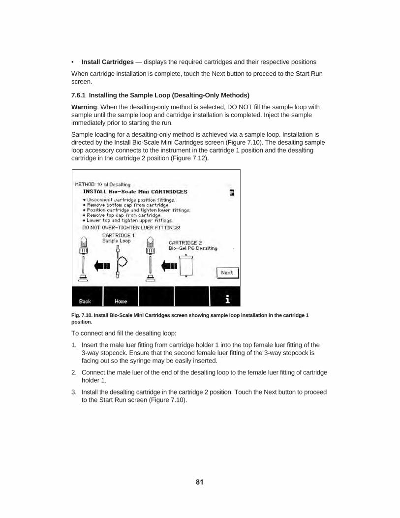
• Install Cartridges — displays the required cartridges and their respective positions
When cartridge installation is complete, touch the Next button to proceed to the Start Runscreen.
7.6.1 Installing the Sample Loop (Desalting-Only Methods)
Warning: When the desalting-only method is selected, DO NOT fill the sample loop withsample until the sample loop and cartridge installation is completed. Inject the sampleimmediately prior to starting the run.
Sample loading for a desalting-only method is achieved via a sample loop. Installation isdirected by the Install Bio-Scale Mini Cartridges screen (Figure 7.10). The desalting sampleloop accessory connects to the instrument in the cartridge 1 position and the desalting cartridge in the cartridge 2 position (Figure 7.12).
Fig. 7.10. Install Bio-Scale Mini Cartridges screen showing sample loop installation in the cartridge 1 position.
To connect and fill the desalting loop:
1. Insert the male luer fitting from cartridge holder 1 into the top female luer fitting of the 3-way stopcock. Ensure that the second female luer fitting of the 3-way stopcock is facing out so the syringe may be easily inserted.
2. Connect the male luer of the end of the desalting loop to the female luer fitting of cartridgeholder 1.
3. Install the desalting cartridge in the cartridge 2 position. Touch the Next button to proceedto the Start Run screen (Figure 7.10).
81

Fig. 7.11. Start Run screen directs application of the sample to the sample loop (desalting-only method).
4. To apply sample, fill the syringe and insert it into the open female luer of the 3-waystopcock. Turn the 3-way stopcock lever down toward the loop and fill the loop withsample, avoiding bubbles as much as possible.
5. Return the 3-way stopcock lever to the middle position, facing toward the syringe. Thedesalting loop is now filled with sample and ready for the desalting method to begin.
Fig. 7.12. Sample loop installed in the cartridge 1 position.
Note: Determine the appropriate combination of desalting loop and desalting cartridge forthe protein sample volume to be applied. For a 2 ml sample, choose the 2 ml desalting loopand the 10 ml desalting cartridge. For a 10 ml sample, choose the 10 ml desalting loop andthe 50 ml desalting cartridge. Application of a sample volume smaller than the desaltingloop volume is not recommended, since it will result in increased dilution of the sample andreduced desalting resolution.
82

7.7 Viewing Real-Time Data With Profinia Software To collect real-time data:
1. Connect the USB cable provided with the Profinia software package to the USB port onthe back of the instrument and to the computer.
Important: The front USB port does not output real-time data.
2. Open Profinia software on your computer by double-clicking on the desktop Profiniasoftware icon. Look for the connection icon in the Profinia software in the lower left corner of the software screen (see section 12 for more information on using Profiniasoftware.
At this point, the run can be started and the chromatogram displays on the computerscreen.
7.8 Starting the RunThe Start Run screen (Figure 7.13) displays a summary of the sample information. It alsodisplays a reminder to connect the instrument to a computer running Profinia software ifyou would like to view the chromatogram in real time. The Profinia system does not requiresoftware and a computer to operate the instrument; current data points appear on the running screen.
The lower toolbar contains buttons for viewing the methods steps and for optional manualpriming of any extra tubing attached to the sample, buffer, diluent, or waste lines to accommodate larger containers in these ports.
Note: Touching the Home button returns the user directly to the home screen and all therun and sample information resets, except the lot number tracking information. A savedmethod remains stored in memory. An edited method that is not saved reverts to the originalsettings.
Fig. 7.13. Start Run screen.
83

7.8.1 Viewing Steps
Touch the View Steps button (available on the Start Run screen, and at any point during therun) to retrieve the View Method Steps screen. During a run, the step that is currently inprogress is highlighted.
7.8.2 Running the Manual Prime Function
Note: The manual prime function is needed to prime any extra tubing up to the point of connection to original inlets.
To prime extra tubing attached to buffer, sample, fraction tube, diluent, or waste outlets toaccommodate larger containers, touch the Manually Prime button at the bottom of the StartRun screen. The Select Item to Prime Manually screen displays (Figure 7.14).
Fig. 7.14. Select Item to Prime Manually screen.
1. Touch the arrow buttons to scroll through the list of reagent lines and highlight the linethat requires manual priming.
2. Touch the Prime button to start priming. The pump continues priming until you touchthe Stop button.
3. Select the next reagent line for manual priming (if needed), and press Prime.
4. Continue until all reagent lines connected with extra tubing have been primed.
Note: Prime lines until no air is visible in the tubing or when fluid is seen entering the waste container.
Priming Multiple Lines
To prime multiple lines, either follow the procedure outlined in the previous section, or:
1. Touch the arrow buttons to scroll through the list of reagent lines, highlight the desiredline, then touch the Prime button.
2. While the system is priming the first reagent line, use the arrow buttons to select thenext reagent line (priming of the first line continues).
84

3. Touch the Prime button again to immediately start priming the next selected reagentline upon completion of the first selected line.
4. Repeat until all the required reagent lines are primed, then touch the Stop button to stopthe pump.
When all manual priming is completed, touch the Back button in the toolbar to return to theStart Run screen.
7.8.3 Clearing System Memory to Start Run
To start your purification run:
Touch the Start button in the lower right of the screen. The Preparing Data MemoryStorage screen displays with a progress bar indicating temporary memory data clearance.
Note: The system can store up to three run data files in memory. An “M” status indicator displayed in the upper right corner of the screen indicates none of the run data files storedin system memory have been transferred. If system memory is full, the oldest transferred orstored data file will be overwritten with the new file when a purification run is started.
Once memory has cleared, the method starts and the Run in Progress screen displays.
7.9 Monitoring Run ProgressThe Run in Progress screen (Figure 7.15) displays an overview of the progress of the current run, as well as basic details about the current step in progress and expected sampleelution times (see section 6.8.1 for a complete list of screen features).
Fig. 7.15. Run in Progress screen.
7.9.1 Peak Detection
Affinity and desalting protein peaks are identified using an automatic peak detection algorithm that is active during elution steps on the Profinia instrument. In addition to automaticpeak detection, the option to manually detect and divert the protein peak is also availableduring affinity and desalting elution step(s). When manual peak detection is available, themanual peak detect/divert button displays on the Run In Progress screen. See section 6.8.2for details on automatic and manual peak detection.
85

7.9.2 Collecting Purified Sample
The purified sample is collected in fraction tube position 1D or 2D. When the purified protein is collected, the Run in Progress screen displays the actual elution times and the tubecan be removed. After the target protein has eluted, the Profinia system will automaticallycontinue to run the cartridge cleaning and storage procedures and process the second sampleif selected.
7.9.3 Completing the Run
Run results display as soon as the end-of-run cleaning procedures are completed.
7.10 Preparing System for End-of-Run CleaningSystem cleaning is an automatic feature that occurs upon completion of each method runand is required to prevent cross-contamination between runs and to maintain the systemfor optimum operation. The two sample lines and the fraction line valve (all eight fractionlines) will be cleaned as part of the end-of-run cleaning process. The pump seals are alsowashed as the final step in this process and the internal system lines are cleaned with 20% ethanol from buffer position 8.
7.10.1 Preparing for Line Cleaning
To prepare the system for end-of-run cleaning:
1. Remove all sample tubes from the instrument.
2. Place tubes containing 10 ml of deionized water in both sample 1 and sample 2 positions;place water in both sample positions even if only one sample was used in the run.
3. Fill a buffer bottle with 20% ethanol and place it in buffer position 8.
4. Remove all fraction collection tubes from the instrument.
5. Place the cleaning tray (provided with the instrument) in the fraction collection area.
6. Touch the Start button to begin the cleaning procedure.
You will proceed to the System Cleaning in Progress screen.
7.10.2 System Cleaning in Progress Screen
When system cleaning starts, the System Cleaning in Progress screen displays the foursystem cleaning procedures: Clean Sample Lines, Clean Fraction Lines, Clean BufferLines, and System EtOH Wash. The cleaning steps that will be performed after a run iscompleted are indicated by darkened circles. A checkmark adjacent to a darkened circleindicates the cleaning step has been completed. When the cleaning process is completed,you will proceed to the Run Completed screen and the run results are displayed.
7.11 Performing End-of-Run ProceduresThe Run Completed screen (Figure 7.16) is displayed on completion of all purification runsteps, including system cleaning. Run details for each sample purified are displayed in therun data table. The total estimated protein (yield) and protein concentration have been calculated and are displayed for each sample.
86

Fig. 7.16. Run Completed screen.
7.11.1 Exporting Data to a Computer
The run data file can be transferred to a portable memory device as an .ofi file, which canbe imported into Profinia software (optional) for viewing data in tabular form and in a chromatogram. If Profinia software has not been purchased, the data file can be viewed inany compatible spreadsheet software (for example, Microsoft Excel). To export the rundata file:
1. Insert a USB portable memory device into the USB port directly below the touch screen.The Export Data button is initially displayed with an “X” across it, indicating that the button is not yet functional. As soon as the system recognizes the portable memorydevice, the “X” disappears and the Export Data button is available. The time requiredfor recognition depends on the portable memory device used and can take up to 15 sec.(See the troubleshooting details in Appendix C if the memory device is not recognized.)
2. Touch the Export Data button. A progress bar displays indicating that the transfer is inprogress; typical transfer time is approximately 60 sec. The actual transfer timedepends on the amount of data in the run data file and the portable drive.
Upon completion of data export, you will automatically return to the Run Completed screen.
7.11.2 Performing Final Run Procedures
The toolbar at the bottom of the Run Completed screen displays the final steps to shut down the system or prepare for a new run. Choose one of the following options:
• Re-Run Method — immediately begin a new sample run with the same method
• Run New Method — immediately begin performing another purification run using a different method type, or new buffers for the run that was just performed
• Short-Term Wash — if the system will not be used again on the same day, the bufferlines and valves should be rinsed with water
• Long-Term Wash — if the system will not be used in the next 2 days, it should berinsed with water and ethanol or other sanitizer to maintain optimum mechanical performance and prevent bacterial growth
See section 6.10.2 for details on performing final run procedures.
87

Important: When the Profinia system is used in a cold environment, it is best to leaveinstrument power on; the slight amount of heat generated helps control condensation. TheUV lamp automatically turns off one hour after the last separation run, and turns back onwhen instrument operation resumes. If the instrument will be stored long term in a cold environment, it is acceptable to turn the power off. When the instrument is removed from acold environment, the unit must be equilibrated to room temperature. This prevents condensation from forming which could possibly be damaging to internal components.
88

Section 8 Saved MethodsThe Profinia™ instrument can store up to 35 program methods in memory. Saved methodscan be retrieved alphabetically according to the method name assigned by the user duringprogramming, by method type, or as a single list of all stored methods. Program methodscan be retrieved from memory for subsequent runs or used as method templates for additional customizing. Saved methods are retrieved directly from the home screen (Figure 8.1) through the Saved Methods menu.
Fig. 8.1. System home screen.
Run data and parameters retained in saved program methods include:
• Method name
• Username
• Date method created
• Flow rate
• Column volume
• Buffer concentration
• Peak detection thresholds
Sample volumes and other run-specific information are not retained with saved programmethods and need to be entered when running a saved method.
Note: Make sure the correct method temperature is selected for saved methods thatinclude the desalting step.
8.1 Retrieving Saved MethodsTo retrieve methods saved in system memory:
1. Touch the Saved Methods button in the toolbar on the home screen. You will proceedto the Select Saved Method System to View screen.
89

2. Use the arrows to select the viewing mode by: “Method System” or “All MethodSystems”. Touch the Next button to proceed to the Select Saved Method screen.
8.2 Selecting Saved MethodsIn the Select Saved Method screen (Figure 8.3), immediately above the list of saved methods,the date the method was created, the username (person who created the method), and themethod type display for the highlighted method.
Note: To ensure that you are listed as the person who created your method, make sureyou enter your name in the Username field of the Enter Run & Sample Information screenwhen programming a method.
Note: System date and time settings can be modified under the Data/Utilities menu; seesection 9.3.3 for more information.
Fig. 8.2. Select Saved Method screen with username, creation date, and method type displayed for thehighlighted stored method.
The following options are available in the Select Saved Method screen:
• Delete — deletes the selected method only; a popup message appears, requestingconfirmation
• Rename — renames the selected method; the old name will be overwritten with thenew name. To create a duplicate method with a different name press Select, edit themethod name in the Enter Run & Sample Information screen, and press Save; this isthe equivalent to a “save as” function
• Select — opens the highlighted method and proceeds to the Enter Run & SampleInformation screen
• Back — returns to the Select Method Type to View screen
• i — retrieves help information about the screen
8.3 Running Saved MethodsTo run a saved method, highlight the desired method from the Select Saved Methodscreen and touch the Select button to proceed to the Enter Run & Sample Information
90

screen (Figure 8.3). See section 7.3 for details on editing the method and entering run andsample information.
Fig. 8.3. Enter Run & Sample Information screen retrieved when saved method is selected.
The following options are available in the Enter Run & Sample Information screen:
• Save — saves revised information (button displays only when edits have been made).Touch the Save button to store the edited method to memory
Note: The Save button in this screen is programmed as a “save as” function. When thename of a saved method is edited in the Enter Run & Sample Information screen, thenewly named method is stored in memory in addition to the original saved method. Apopup message displays, indicating method memory is full when 35 methods are stored.You will need to delete a method prior to saving a new method. The new method can berun without saving it to memory. When memory is full, the upper right status corner of thescreen displays “F”.
• Edit — accesses the alphanumeric or numeric keypad to edit method name, username,and run and sample information
• Edit method — accesses the method steps for editing the individual step parameters
• Back — returns to the Select Method Type & Options screen; allows editing of themethod options
• Save — Methods — returns to the “Select saved Method System to View” screen
For details on setting up and starting the run, see section 6.
Important note for Program Methods users:
The saved methods using older version of firmware may not work properly usingnewer versions of firmware. The best practice is to record the parameters saved inthe old methods and reprogram it as a new method on the new firmware. Refer toAppendix K for Profinia planning worksheets to record parameter changes.
91
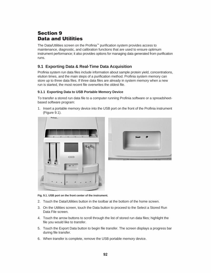
Section 9 Data and UtilitiesThe Data/Utilities screen on the Profinia™ purification system provides access to maintenance, diagnostic, and calibration functions that are used to ensure optimum instrument performance; it also provides options for managing data generated from purificationruns.
9.1 Exporting Data & Real-Time Data AcquisitionProfinia system run data files include information about sample protein yield, concentrations,elution times, and the main steps of a purification method. Profinia system memory canstore up to three data files. If three data files are already in system memory when a newrun is started, the most recent file overwrites the oldest file.
9.1.1 Exporting Data to USB Portable Memory Device
To transfer a stored run data file to a computer running Profinia software or a spreadsheet-based software program:
1. Insert a portable memory device into the USB port on the front of the Profinia instrument(Figure 9.1).
Fig. 9.1. USB port on the front center of the instrument.
2. Touch the Data/Utilities button in the toolbar at the bottom of the home screen.
3. On the Utilities screen, touch the Data button to proceed to the Select a Stored RunData File screen.
4. Touch the arrow buttons to scroll through the list of stored run data files; highlight thefile you would like to transfer.
5. Touch the Export Data button to begin file transfer. The screen displays a progress barduring file transfer.
6. When transfer is complete, remove the USB portable memory device.
92

Warning: Most USB portable memory devices display a flashing light when data is beingtransferred. Wait until the light stops flashing, an indication that the file transfer is complete,before removing the portable memory device from the instrument.
Note: An asterisk appears next to run data files that have been transferred to a USBportable memory device.
9.1.2 Real-Time Data Transfer to Profinia Software
To transfer a run data file from the Profinia system to a computer in real time:
1. Before starting your purification run, use the USB cable provided with Profinia softwareto connect the instrument (using the USB port on the back of the instrument) to a computer that has Profinia software installed.
Important: To capture data in real time, the USB cable connection must be establishedprior to starting a purification run.
2. Open Profinia software on the computer. A connection between the software and theinstrument will be indicated by a “Waiting for data” message at the bottom of theProfinia software screen on your computer (Figure 9.2). This message indicates that arun can be started.
Fig. 9.2. “Waiting for data” message on the bottom of the Profinia software screen.
3. Use the directory section of Profinia software in the upper left corner of the screen todetermine where you want your data file stored on your computer (see section 12 forgeneral information on running Profinia software).
4. Select Default from the software Options menu, and use Browse to select the file orcreate a new file in the Profinia instrument for your run data information.
5. Touch the Start button on the Start Run screen.
Data from your purification displays in real time on your computer screen as the run progresses.
9.2 System UtilitiesThe following list of calibration functions is accessible from the system menu on the Utilitiesscreen:
• Calibrate Touch Screen • Pump Flow Rate Check• Calibrate UV Monitors• Calibrate Conductivity • Adjust Peak Detection Sensitivity• Calibrate pH Probe• Calibrate Air Detection System
93

• Calibrate Pressure Sensor
9.2.1 Calibrating Touch Screen
To calibrate the system touch screen:
1. Touch the Data/Utilities button from the system home screen, then touch the Diag/MaintFunctions button.
2. Touch the up and down arrows to scroll through the list of functions and highlight“Calibrate Touch Screen”, then touch the Select button.
3. Use the stylus to tap the center of five consecutive screen targets (Figure 9.3). Whenyou touch the center of the last confirmation target in the center of the screen, the system returns to the Home screen.
Fig. 9.3. Touch screen calibration screen.
9.2.2 Checking Pump Flow Rate
The Profinia instrument’s pump does not require calibration. If the fraction size is not asexpected or other symptoms are seen, check the flow rate. If the flow rate is not withinspecifications, clean the system check valves and replace the inline filter disk (see section13.2 for more details). The following items are required to check the pump:
• Graduated cylinder — suitable for measuring the volume of water delivered
• Deionized water — Profinia diluent (water) bottle filled to 200 ml
To check the pump flow rate:
1. Touch the Data/Utilities button in the toolbar at the bottom of the home screen, thentouch Calibration Functions.
2. Touch the up and down arrows to scroll through the list of calibration functions andhighlight “Pump Flow Rate Check”, then touch Select; an information screen appears.
3. Touch the Next button to proceed to the Calibration screen.
4. Touch the Edit button to choose the flow rate, then touch the Edit button again to setthe time for the flow rate test using the alphanumeric keypad.
94

5. Touch the Start button; the system pumps water from the water bottle to the waste outlet to remove air from the system and the delivery tube. When the step is finished,the screen displays “Priming Complete” and additional instructions.
6. Remove the waste line from the waste bottle and place the waste line in an empty graduated cylinder.
7. Touch Start to pump deionized water through the system at the flow rate and for theduration set in step 4.
8. When the test is complete the system displays "Flow Rate Check Completed". Note theexpected quantity on the screen. The actual quantity delivered when bypassing the cartridged during the flow rate check can be up to 7% over the expected value if thesystem is working optimally. The additional restriction from directing the flow throughthe cartridges during the method will result in the expected quantity displayed on thescreen.
If the quantity is less than the displayed expected quantity, change the inline filter disk andmake sure that all the air has been purged from the system before repeating the test procedure.
If you continue to have problems with system flow rates, clean or replace the pump checkvalves (Section 13.2.1) or replace the pump seals (Section 13.2.2). If the system still doesnot operate normally, contact your local Bio-Rad office for assistance.
9.2.3 Calibrating UV Monitors
You may wish to calibrate the UV monitors using a protein similar to your protein of interestfor improved quantitation. The following materials are required to calibrate the UV monitors:
Protein solution of known absorbance — prepare a protein solution and measure itsabsorbance in a spectrophotometer at 280 nm. The absorbance value for a 1 cm pathlengthwill be entered prior to the calibration process. Note:
• Choose a solution that has an absorbance reading less than 2 AU at 280 nm, for a1 cm pathlength on the spectrophotometer
• If you use a cuvette that is less than 1 cm pathlength, correct the absorbance reading to 1 cm. For example, if you use a 2 mm cuvette, multiply the reading by 5 and enter this value in the calibration screen
• Choose a solution that has an absorbance reading less than 1 unit on the UV monitor(the instrument has a 2 mm pathlength)
• A protein concentration of 1–2 mg/ml is a suggested starting point
Deionized water — 45 ml in a 50 ml sample tube; 500 ml in the diluent (water) bottle forplacement in the system’s Di water port
20% ethanol solution — 100 ml in a Profinia 125 ml buffer bottle
To calibrate the UV monitors:
1. Fill a 125 ml Profinia buffer bottle with 20% ethanol and place it in buffer position 8.
2. Prepare the standard protein solution and measure its absorbance at 280 nm. Correctthe absorbance value to 1 cm pathlength.
3. Fill a 50 ml sample tube with 45 ml of this UV absorbance standard solution, and placeit in sample position 1.
95

4. Fill a 50 ml sample tube with 45 ml of deionized water, and reserve it for later use (towash sample line 1 when calibration is complete).
5. Fill the diluent (water) bottle to 500 ml with deionized water, and place it in the Di waterport.
Note: Make sure to empty the waste bottle before performing this procedure to preventoverflow.
6. Turn the Profinia instrument on.
7. Touch the Data/Utilities button on the system home screen, then touch CalibrationFunctions.
8. Touch the up and down arrows to scroll through the list of functions and highlight“Calibrate UV Monitors”, then touch Select; the UV Calibration Information screenappears.
9. Touch the Next button; you will proceed to the Calibrate UV Monitors screen.
Note:The screen displays the UV-1 and UV-2 values, as well as the C (correction) factorsfor each of the two monitors.
10. Touch the Edit button to enter the absorbance of your standard solution (in absorbanceunits per centimeter) into the alphanumeric keypad. Touch the OK button to confirm.
11. Touch the Start button. The instrument will:
a) Pump ethanol through both UV flow cells.
b) Rinse the UV flow cells with water.
c) Zero the UV monitors on water.
d) Fill the UV flow cells with the protein solution.
e) Set the UV absorbance value for both UV monitors to the absorbance valueentered in step 10.
12. Upon completion of these procedures, the instrument displays “UV Calibration complete— Place tube of DI water at sample position 1”. Place the tube filled with deionizedwater in sample position 1, then touch the Start button. The system washes with water,then returns to the Calibration Functions screen.
9.2.4 Calibrating Conductivity
The Profinia system’s conductivity monitor is calibrated during instrument manufacturing,and generally does not require calibration unless the conductivity flow cell is replaced. Thefollowing materials are required to calibrate the conductivity monitor:
• Conductivity standard solution — conductivity 10 millisiemens per centimeter(mS/cm); 45 ml of solution is required
• Deionized water — 45 ml in a 50 ml sample tube, 500 ml in the diluent (water) bottlefor placement in the system’s Di water port
To calibrate the conductivity monitor:
1. Turn the instrument on; the system should warm up for 20 min before calibrating theconductivity monitor.
2. Fill a 50 ml sample tube with 45 ml of conductivity standard solution, then place it insample position 1.
96

3. Fill the system’s water bottle with at least 500 ml of deionized water. Empty the wastebottle if needed.
4. Touch the Data/Utilities button on the system’s home screen, then touch CalibrationFunctions.
5. Touch the up and down arrows to scroll through the list of functions and highlight“Calibrate Conductivity Monitor”, then touch Select to display the Calibrate Conductivityscreen.
6. Touch Next to proceed to the Calibrate Conductivity Flow Cell screen, which displayscalibration instructions.
7. Touch the Start button. The system pumps conductivity standard solution through theconductivity flow cell, then set conductivity to 10 mS/cm. When finished with this step,the system will pause and display “Calibration Complete”.
8. Place the tube of water in sample position 1, then touch the OK button. The systemflushes the sample line with water and when complete, returns to the CalibrationFunctions screen.
9.2.5 Adjusting Peak Detection Sensitivity
Peak detection sensitivity settings range between 0.1 (most sensitive) and 10 (least sensitive); the default setting is 1. Peak detection sensitivity is a global setting for both theBio-Rad methods and the program methods modes. The peak detection sensitivity parameterallows the instrument to adjust the automatic peak detection algorithm to various peakshapes and sizes in the event the default setting does not recognize a peak during thespecified time window. In general, use lower numbers (more sensitive) if a small proteinpeak is expected.
Note: Using more sensitive settings for peak detection may lead to activation of automaticpeak detection from small deviations in the UV that are not associated with the proteinpeak.
To adjust peak detection sensitivity settings:
1. Touch the Data/Utilities button on the system home screen, then touch CalibrationFunctions.
2. Touch the up and down arrows to scroll through the list of functions and highlight“Adjust Peak Detection Sensitivity”, then touch the Select button; the numeric keypaddisplays.
3. Enter a value between 0.1 and 10, then press OK to return to the Calibration Functionsscreen.
9.2.6 Calibrating pH Probe
The Profinia pH monitor is calibrated at pH 4 and pH 10. The following materials arerequired to calibrate the pH probe:
• Standard pH calibration buffers — available from scientific supply companies;approximately 50 ml of each buffer is required to calibrate the system. Using colorlessstandards is recommended, since certain dye additives require additional wash stepsfor removal
• Deionized water — diluent (water) bottle filled to 500 ml, and two sample tubes to 50 mlto flush the system after calibration
97

To calibrate the pH probe:
1. Touch the Data/Utilities button on the system home screen, then touch CalibrationFunctions.
2. Touch the up and down arrows to scroll through the list of functions and highlight“Calibrate pH Probe”, then touch the Select button. An information screen appears.
3. Touch the Next button; the Calibrate pH Probe screen displays with a list of detailedinstructions.
4. Pour 50 ml of each pH buffer (pH 4 and pH 10) in separate 50 ml sample tubes.
5. Place the bottle containing the pH 4 buffer in sample position 1.
6. Place the bottle containing the pH 10 buffer in sample position 2.
7. Touch the Start button. The system will:
a) Flush the pH probe with water.
b) Pump pH 4 buffer to prime sample line 1 and the pH probe. The system reducesthe flow rate and sets the pH value to 4.
c) Pump pH 10 buffer to prime sample line 2 and the pH probe. The system reducesthe flow rate and sets the pH value to 10. The system pauses and displays “pHProbe Calibration Complete”.
8. Replace the tubes of pH buffer (sample positions 1 and 2) with 50 ml tubes filled withdeionized water.
9. Touch the Start button. The system flushes the lines with water, then returns to theCalibration Functions screen.
9.2.7 Calibrating Air Detection System
Calibration of the three air sensors is required for optimum performance. The calibrationprocess measures electronic signals of air and liquid to establish the thresholds for end ofsample/reagent detection. To calibrate the air detection system, follow the on screeninstructions.
9.2.8 Calibrating Pressure Sensor
The Pressure Sensor Calibration process contains the re-calibration for the zero point ofthe pressure measuring system. Calibration of the zero pressure point is needed if thepressure reading during non-operation of the system does not return to zero. Access theManual mode from the Data/Utilities section to observe the pressure reading.
To calibrate the zero pressure point, access the Calibrating Pressure Transducer fromHome/Data-Utilities/Calibration Functions and follow the on-screen directions.
9.3 Diagnostic/Maintenance FunctionsThe following list of diagnostic and maintenance functions is accessible from the systemmenu on the Diag/Maint Functions screen (Figure 9.4):
• Display Firmware Version• Manual Operation• Set Time and Date• Clean Sample Lines• Clean Fraction Lines• Clean Buffer Lines• System Ethanol Wash
98

• Clean All Inlet and Outlet Lines• Clean Pump Check Valves• System NaOH Wash• Clean Inline Check Valve• Affinity Cartridge Cleaning in Place• Desalting Cartridge Cleaning in Place• Select End of Sample/Reagent Detection• Select Method Temperature• Adjust Display Contrast
Fig. 9.4. Diag/Maint Functions screen.
9.3.1 Displaying Firmware Versions
To retrieve the version numbers for the system’s main firmware components:
1. Touch the Data/Utilities button on the system home screen.
2. On the Utilities screen, touch the Diag/Maint Functions button.
3. Touch the up and down arrows to scroll through the list of functions and highlight“Display Firmware Versions”, then touch the Select button. The screen displays thefirmware versions for the main board, pump/valve controls, and UV monitor.
4. Note the version numbers for the firmware, then touch OK to return to the Diag/MaintFunctions screen.
9.3.2 Setting and Operating Instrument Manually
Manual operation allows you to set the system valves in a desired position and manuallyrun the system pump. Refer to the schematic diagram below (Figure 9.5) to identify whichcomponent you want to control.
99

Fig. 9.5. Diagram of all internal Profinia system hardware components.
The adjustable components are:
Pump flow rate — set in ml/min. After a flow rate is entered into the Edit menu and youtouch the Update button, the pump starts. To stop the pump, press the Stop Pump buttonon the bottom of the screen
Inlet select valve (ISV) — rotary valve (10 port) that selects the buffer or sample. After youenter a valve position into the Edit menu and touch the Update button, the valve moves
• Positions 1 through 8 are buffers 1 through 8
• Positions 9 and 10 are samples 1 and 2
100

Outlet select valve (OSV) — rotary valve (10 port) that directs system output. After a valveposition is entered in the Edit menu and you touch the Update button on the ManualOperation screen, the valve moves
• Positions 1 through 4 are fractions 1A through 1D
• Positions 5 through 8 are fractions 2A through 2D
• Position 9 is the fraction collector outlet
• Position 10 is the system waste outlet
Column valve 1 (CV1) — rotary valve (6 port) that directs the flow for cartridge 1. After avalve position is entered in the Edit menu and the Update button is pressed on the ManualOperation screen, the valve will move
• Position 1 directs flow to the system waste outlet
• Position 2 directs flow to flush behind the pump pistons
• Position 5 directs flow to column valve 2
• Position 6 directs flow to cartridge 1
• All other valve ports are plugged
Column valve 2 (CV2) — rotary valve (6 port) that directs the flow for cartridge 1. After avalve position is entered in the Edit menu and the Update button is pressed on the ManualOperation screen, the valve will move
• Position 4 directs flow to the system waste outlet
• Position 5 directs flow to the conductivity monitor, pH monitor (optional) and to theoutlet select valve
• Position 6 directs flow to cartridge 2
• All other valve ports are plugged
Proportioning valve (PV) — solenoid valve (3 port, 2 position). The proportioning valvemixes concentrated buffer from the inlet select valve with water from the system water bottle. Position settings are 0x, and 1x through 5x:
• 0x draws 100% water from the water bottle
• 1x draws 100% buffer from the inlet select valve (ISV)
• 2x makes a 1:1 concentrate/water mixture
• 3x makes a 1:2 concentrate/water mixture
• 4x makes a 1:3 concentrate/water mixture
• 5x makes a 1:4 concentrate/water mixture
The proportioning valve operates only when the pump is running. The timing of the valvedepends on the pump flow rate
Warning: Use care when controlling components manually. Improper settings may damagethe cartridges or system components.
101

Manual control toolbar — buttons (5) at the bottom of the Manual Operations screen(Figure 9.6) that control:
• Toggle lamp — switches the UV lamp on or off: a light bulb icon in the upper leftcorner of the screen indicates that the UV lamp is on. Normally the Profinia lampwill turn off one hour after the last run is finished. If the lamp is manually switchedon, it will remain on until it is manually switched off
• Zero UV Detector 1 — sets the absorbance of UV monitor 1 to zero
• Zero UV Detector 2 — sets the absorbance of UV monitor 2 to zero
• Stop Pump — stops the system buffer pump, if running
• OK — returns to the Diag/Maint Functions screen
Fig. 9.6. Manual Operation of Hardware screen.
To access the manual operation features:
1. Touch the Data/Utilities button on the system home screen.
2. Touch the Diag/Maint Functions button.
3. Touch the up and down arrows to scroll through the list of functions and highlight“Manual Operation”, then touch the Select button.
The Manual Operation screen has three parts — the status screen, the manual operationscreen, and the toolbar (near the bottom of the screen):
Status screen — top of the Manual Operation screen, includes information regarding:
• PSI — system pressure value
• pH — value for pH. If pH probe is not connected the value shown is ~25
• T — system temperature value
• AU1 and AU2 — absorbance values for UV monitor 1 and UV monitor 2
• VR1 and VR2 — lamp operation indicator; must be greater than 0.05 volts
• VS1 and VS2 — flow cell operation indicator; must be greater then 65% of the VRvalue
• C — conductivity value in mS
102

Manual control screen — center section of the screen, for manually operating systemcomponents
Toolbar — lower section of the screen, includes command button options described in section 3.3
To change the system component settings prior to starting a run:
1. On the Manual Operation screen, touch the up and down arrows to scroll through thelist of components and highlight a component to manually operate.
2. Touch the Edit button to retrieve the numeric keypad.
3. Enter the value (for example, flow rate, valve position, proportioning percent) desired.
4. Touch OK to confirm and return to the main screen.
5. When all values on the screen are set correctly, touch Update to start the system asdescribed for each component in the list of adjustable components above.
To change the system component settings when a run is in progress:
1. On the Manual Operation screen, touch the arrow buttons to highlight the desired com-ponent.
2. Touch the Edit button to retrieve the numeric keypad and enter the new values; touchOK to return to the Manual Operation screen.
3. Touch Update to continue the run with the new settings.
103

9.3.3 Setting Time and Date
To change the system date and time settings (Figure 9.7):
1. Touch the Data/Utilities button on the system home screen.
2. Touch the Diag/Maint Functions button.
3. On the Diag/Maint Functions screen, touch the up and down arrows to scroll throughthe list of functions and highlight “Set Time and Date”, then touch the Select button.
4. Touch the up and down arrows next to each date and time setting to adjust for local settings; press OK to save selections and return to the Diag/Maint Functions screen.
Fig. 9.7. Set Time & Date screen.
104

9.3.4 Cleaning Sample Lines
This procedure is used to clean the two sample lines; buffer position 8 holds the 20%ethanol solution and is used as a final system purge:
1. Touch the Data/Utilities button on the system home screen.
2. Touch the Diag/Maint Functions button.
3. On the Diag/Maint Functions screen, touch the up and down arrows to scroll throughthe list of functions and highlight “Clean Sample Lines”, then touch the Select button.
4. Follow the directions displayed on the screen (Figure 9.8).
5. Touch the Start button. The system washes the sample lines with water followed by asystem purge with ethanol from buffer position 8. A progress bar displays while cleaningis in process.
When cleaning is complete, the system returns to the Diag/Maint Functions screen.
Fig. 9.8. Prepare system to clean sample lines screen.
105
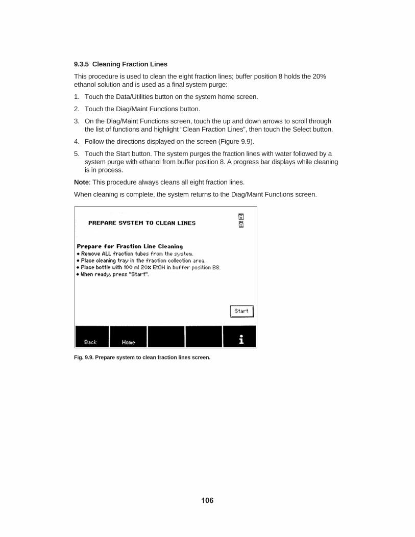
9.3.5 Cleaning Fraction Lines
This procedure is used to clean the eight fraction lines; buffer position 8 holds the 20%ethanol solution and is used as a final system purge:
1. Touch the Data/Utilities button on the system home screen.
2. Touch the Diag/Maint Functions button.
3. On the Diag/Maint Functions screen, touch the up and down arrows to scroll throughthe list of functions and highlight “Clean Fraction Lines”, then touch the Select button.
4. Follow the directions displayed on the screen (Figure 9.9).
5. Touch the Start button. The system purges the fraction lines with water followed by asystem purge with ethanol from buffer position 8. A progress bar displays while cleaningis in process.
Note: This procedure always cleans all eight fraction lines.
When cleaning is complete, the system returns to the Diag/Maint Functions screen.
Fig. 9.9. Prepare system to clean fraction lines screen.
106

9.3.6 Cleaning Buffer Lines
This procedure is used to clean buffer lines 1 through 7; buffer position 8 holds the 20%ethanol solution and is used as a final system purge:
1. Touch the Data/Utilities button on the system home screen.
2. Touch the Diag/Maint Functions button.
3. On the Diag/Maint Functions screen, touch the up and down arrows to scroll throughthe list of functions and highlight “Clean Buffer Lines”, then touch the Select button.
4. Follow the directions displayed on the screen (Figure 9.10).
5. Touch the Start button. The system purges buffer lines 1 through 7 with water, followedby a system purge with ethanol from buffer position 8. A progress bar displays whilecleaning is in process.
When cleaning is complete, the system returns to the Diag/Maint Functions screen.
Fig. 9.10. Prepare system to clean buffer lines screen.
107

9.3.7 Washing System With Ethanol
This procedure is used to clean the complete system with ethanol; all buffer lines, sample lines, fraction lines, cartridge position lines, and valve positions are purged withethanol:
Note: If the buffer and sample inlet lines and the fraction outlet lines are stored withethanol, make sure to wash these lines with water prior to starting a new method using the“Clean All Inlet and Outlet Lines” procedure (section 9.3.8).
1. Touch the Data/Utilities button on the system home screen.
2. Touch the Diag/Maint Functions button.
3. On the Diag/Maint Functions screen, touch the up and down arrows to scroll throughthe list of functions and highlight “System Ethanol Wash”, then touch the Select button.
4. Follow the reagent placement instructions displayed on the screen (Figure 9.11).
5. Remove both cartridges and connect the cartridge fittings.
6. Remove all fraction tubes and replace them with the cleaning tray or empty fractiontubes.
7. Touch the Start button; the system flushes the internal flow paths. A progress bar displayswhile cleaning is in process.
8. When system flush is complete, touch OK to return to the Diag/Maint Functions screen.
Fig. 9.11. Prepare System to Clean Lines, system ethanol wash screen.
108

9.3.8 Cleaning Inlet and Outlet Lines
This procedure cleans all buffer and sample inlet lines and fraction outlet lines, followed bya system purge with ethanol from buffer position 8:
1. Touch the Data/Utilities button on the system home screen.
2. Touch the Diag/Maint Functions button.
3. On the Diag/Maint Functions screen, touch the up and down arrows to scroll throughthe list of functions and highlight “Clean All Inlet and Outlet Lines”, then touch the Selectbutton.
4. Follow reagent placement instructions displayed on the screen (Figure 9.12).
5. Touch the Start button; the system flushes the lines with water, followed by a systempurge with ethanol from buffer position 8. A progress bar displays while cleaning is inprogress.
When cleaning is complete, the system will return to the Diag/Maint Functions screen.
Fig. 9.12. Clean All Inlet and Outlet Lines screen.
109

9.3.9 Cleaning Pump Check Valves
Use this procedure to pump 0.5 M sodium hydroxide (NaOH) solution through the pump toclean the check valves:
1. Touch the Data/Utilities button on the system home screen.
2. Touch the Diag/Maint Functions button.
3. On the Diag/Maint Functions screen, touch the up and down arrows to scroll throughthe list of functions and highlight “Clean Pump Check Valves”, then touch the Selectbutton.
4. Follow instructions displayed on the screen (Figure 9.13).
5. Fill one buffer bottle with 50 ml of NaOH solution (0.5 M) and place it in buffer position8.
6. Touch the Start button. The system slowly pumps NaOH through the pump for 10 min,followed by a water wash at which point the system pauses. A progress bar displayswhile cleaning is in process.
7. Follow screen instructions for the two available options: 1) Repeat the NaOH wash, or2) Complete the wash (wash the buffer 8 position with water).
8. Touch the Repeat button to repeat the NaOH wash, or touch the Continue button tocomplete the procedure. A progress bar displays while cleaning is in process.
When cleaning is complete, the system returns to the Diag/Maint Functions screen.
Fig. 9.13. Pump Check Valve Cleaning screen.
110

9.3.10 Washing System With NaOH
Use this procedure to wash the internal system lines (including the cartridge lines) withNaOH solution:
1. Touch the Data/Utilities button on the system home screen.
2. Touch the Diag/Maint Functions button.
3. On the Diag/Maint Functions screen, touch the up and down arrows to scroll throughthe list of functions and highlight “System NaOH Wash”, then touch the Select button.
4. Follow instructions displayed on the screen (Figure 9.14).
5. Touch the Start button. The system slowly pumps NaOH through the system for 15 min,followed by a system water wash at which point the system pauses. A progress bar displays while cleaning is in process.
6. Follow screen instructions for the two available options: 1) Repeat the NaOH wash, or2) Complete the wash (wash the buffer 8 position with water).
7. Touch the Repeat button to repeat the NaOH wash, or touch the Continue button tocomplete the procedure. A progress bar will display while cleaning is in process.
When cleaning is complete, the system will return to the Diag/Maint Functions screen.
Fig. 9.14. System NaOH wash screen.
111

9.3.11 Cleaning Inline Check Valve
Use this procedure to manually clean the inline check valve positioned between the cartridge 2 outlet and the fraction valve (outlet selector valve); cleaning the inline checkvalve manually with a syringe allows removal of residue as well as small particles:
1. Touch the Data/Utilities button on the system home screen.
2. Touch the Diag/Maint Functions button.
3. On the Diag/Maint Functions screen, touch the up and down arrows to scroll throughthe list of functions and highlight “Clean Inline Check Valve”, then touch the Select button.
4. Follow instructions displayed on the screen (Figure 9.15).
5. When the manual procedure is complete, touch the Finish button to wash the systemwith water from the diluent bottle. A progress bar displays while cleaning is in process.
When cleaning is complete, the system returns to the Diag/Maint Functions screen.
Fig. 9.15. Clean Inline Check Valve screen.
9.3.12 Affinity Cartridge Cleaning in Place
A convenient cleaning in place method for prepacked 1 ml and 5 ml affinity chromatographycartridges can be accessed through the Profinia Data/Utilities menu. This cleaning in placemethod uses a wash buffer, a cleaning buffer, and a storage buffer. The formulation ofthese buffers depends upon the specific type of affinity cartridge to be cleaned and thenature of the contaminants to be removed. The instruction manual for prepacked affinitychromatography cartridges contains pertinent information on compatible and recommendedcleaning reagents. Note that the formulation for the buffers should not be diluted and needsto be supplied at the working concentration (1x).
1. Touch the Data/Utilities button on the system home screen.
2. Touch the Diag/Maint Functions button.
112

3. On the Diag/Maint Functions screen, touch the up and down arrows to scroll throughthe list of functions and highlight “Affinity Cartridge Cleaning in Place”, then touch theSelect button.
4. Select the size of the cartridge to be cleaned (1 ml or 5 ml).
5. Follow instructions displayed on the screen (Figure 9.16).
6. After the cartridge and reagents have been installed press the Start button.
7. At the end of the cleaning method the user has the option to end or repeat the method.(Repeating the method will subject the cartridge to another cleaning cycle).
The cleaning in place method steps are listed in Table 9.1. Note that 20% aqueous ethanolneeds to be supplied at buffer position 8. This is for system cleaning only and is not part ofthe cleaning in place method. The flow rate for 1 ml and 5 ml cartridges is 1 ml/min and 5ml/min, respectively.
Table 9.1. Steps of the Affinity Cleaning in Place Method
Buffer Buffer Buffer Column Flow Rate (ml/min)Port Conc. Volumes 1 ml Cartridge 5 ml Cartridge
Equilibration B5 1x 2 1 5
Cleaning B6 1x 10 1 5
Equilibration B5 1x 5 1 5
Storage B7 1x 5 1 5
20% Ethanol B8 1x – 1 5
Fig. 9.16. Affinity Cartridge Cleaning in Place screen.
9.3.13 Desalting Cartridge Cleaning in Place
A cleaning in place method for 10 ml and 50 ml Bio-Gel P6 desalting cartridges is availablethrough the Profinia Data/Utilities Menu for storage or cleaning with user defined reagents.This method uses 1x buffer concentrates at predefined flow rates of 4 and 20 ml/min for 10 mland 50 ml cartridges respectively. For Profinia coldroom setting the flow rates are reducedto 2 and 10 ml/min to prevent overpressure (Table 9.2 and Figure 9.17).
113
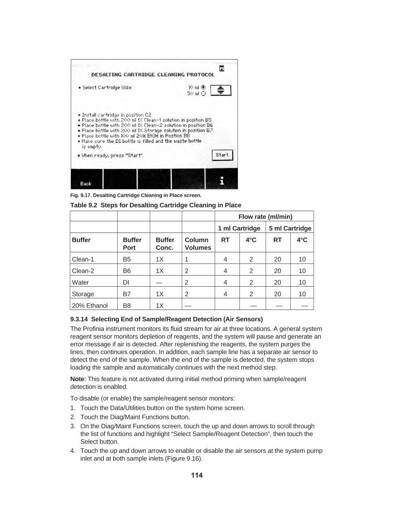
Fig. 9.17. Desalting Cartridge Cleaning in Place screen.
Table 9.2 Steps for Desalting Cartridge Cleaning in Place
Flow rate (ml/min)
1 ml Cartridge 5 ml Cartridge
Buffer Buffer Buffer Column RT 4°C RT 4°CPort Conc. Volumes
Clean-1 B5 1X 1 4 2 20 10
Clean-2 B6 1X 2 4 2 20 10
Water DI — 2 4 2 20 10
Storage B7 1X 2 4 2 20 10
20% Ethanol B8 1X — — — —
9.3.14 Selecting End of Sample/Reagent Detection (Air Sensors)
The Profinia instrument monitors its fluid stream for air at three locations. A general systemreagent sensor monitors depletion of reagents, and the system will pause and generate anerror message if air is detected. After replenishing the reagents, the system purges thelines, then continues operation. In addition, each sample line has a separate air sensor todetect the end of the sample. When the end of the sample is detected, the system stopsloading the sample and automatically continues with the next method step.
Note: This feature is not activated during initial method priming when sample/reagentdetection is enabled.
To disable (or enable) the sample/reagent sensor monitors:
1. Touch the Data/Utilities button on the system home screen.2. Touch the Diag/Maint Functions button.3. On the Diag/Maint Functions screen, touch the up and down arrows to scroll through
the list of functions and highlight “Select Sample/Reagent Detection”, then touch theSelect button.
4. Touch the up and down arrows to enable or disable the air sensors at the system pumpinlet and at both sample inlets (Figure 9.16).
114

5. Select the OK button to confirm selections and return to the Diag/Maint Functionsscreen.
Fig. 9.18. Select End of Sample/Reagent Detection screen.
9.3.15 Selecting Method Temperature
For methods that include the desalting step, the instrument operating temperature is critical.Maximum flow rates for the desalting cartridges are lower at 4°C than at room temperature. Flow rates over maximum limits compress the bed volume and cause over-pressure errors. Make sure the operating temperature is set to match cold room orroom temperature operating conditions before programming your run. Methods with desaltingsteps have longer run times at the cold room setting due to the lower maximum flow rates.The operating temperature setting displays as a status indicator in the upper right corner ofthe screen. If the cold room operating temperature is selected, “C” appears only whenmethods are selected that include a desalting step. If the room temperature setting isselected, “C” will not display. For affinity-only methods, the temperature setting is irrelevantand will not display. See Table 6.1 (section 6) for flow rate details. To set the operatingtemperature:
1. Touch the Data/Utilities button on the system home screen.
2. Touch the Diag/Maint Functions button.
3. On the Diag/Maint Functions screen, use the up and down arrows to scroll through thelist of functions and highlight ”Select Method Temperature”, then touch the Select button.The Select Method Temperature screen will display (Figure 9.18).
4. Use the up and down arrow buttons to select room temperature or cold room (4°C)operation.
5. Touch the OK button to return to the Diag/Maint Function screen.
115

Fig. 9.19. Select Method Temperature screen.
9.3.16 Select Display Contrast
Follow the on-screen instructions to increase or decrease the contrast.
Fig. 9.20. Select display contrast screen.
116

Section 10 Profinia™ Purification Kits
10.1 Introduction
10.1.1 Background
The Profinia protein purification system includes a complete line of consumables that interface with the instrument for the purification of affinity-tagged proteins. The consumablesconsist of standard chromatography buffers, resins, reagents, and accessories that havebeen packaged into a complete, kit-based, and easy-to-use platform. Reagents and purification kits have been developed for the four main types of system applications —native IMAC, denaturing IMAC, GST, and desalting — and include bacterial lysis reagents,prepackaged buffers, IMAC and GST affinity media in prepacked cartridges, and antibodydetection tools. See Appendix B (Ordering Information) for a complete list of Profinia products.
10.1.2 Product Information
Two types of kits can be used for the purification of affinity-tagged proteins: Profinia purification kits and Profinia buffer kits. The all-inclusive Profinia purification kits include two1 ml affinity and two 10 ml desalting cartridges, in addition to a complete set of buffers andsolutions (affinity, desalting*, cleaning, and storage solutions) and reagents (urea and glutathione) required for affinity and desalting applications. Profinia buffer kits are an appropriate choice for those users requiring additional buffers and cleaning reagents, butare not supplied with the affinity or desalting cartridges. The desalting buffer and separationskits contain solutions and cartridges specific for desalting or buffer exchange.
Each kit contains sufficient reagents to perform 10 ml of affinity purifications, followed by100 ml of desalting separations. This can be broken up into ten individual 1 ml affinity cartridge runs, two 5 ml affinity cartridge runs, or a single 5 ml and five 1 ml cartridge runs.The cartridges for affinity/desalting applications are provided as 1 ml/10 ml pairs. Larger 5 ml/50 ml affinity/desalting cartridges can be purchased separately for larger-scale purification runs. Because each ml of IMAC or GST resin typically yields ~10 mg of purifiedprotein, each buffer or purification kit typically yields ~100 mg of purified protein. Table 10.1summarizes the complete line of purification and buffer kits available for the Profinia system.
* Denaturing IMAC kits do not contain desalting cartridges or desalting buffer; stepwise dialysis is the suggestedmethod for desalting and buffer exchange and for renaturing proteins purified under denaturing conditions.
117

Table 10.1. Profinia purification and buffer kits.
Kit Catalog # Solutions Powdered Reagents Cartridges
Purification Desalting Storage Buffers Buffer Solutions Urea Glutathione Affinity Desalting
Profinia Native IMAC Kits
Native IMACpurification kit 620-0225 ✔ ✔ ✔
✔ ✔
Native IMAC buffer kit 620-0221 ✔ ✔ ✔
Profinia Denaturing IMAC Kits
Denaturing IMAC purification kit 620-0227 ✔ ✔ ✔
Denaturing IMACbuffer kit 620-0222 ✔ ✔✔
Profinia GST Kits
GST purification 620-0226 ✔ ✔ ✔ ✔ ✔ ✔kit
GST buffer kit 620-0223 ✔ ✔ ✔ ✔
Profinia Desalting Kits
Desalting 620-0228 ✔ ✔✔
kit
Desalting 620-0224 ✔ ✔buffer kit
10.1.3 Equipment and Materials Required
Profinia purification and buffer kits are specifically designed to be used with the Profiniaprotein purification instrument. All of the buffers and solutions come formulated as concentrates that are made with chromatography-grade solutions, and have been prefilteredto remove particulates. The buffers that require the addition of urea or glutathione alsorequire filtration through a 0.2 µm filter prior to use with the system. Accessories to theProfinia instrument include Profinia software, cooling accessory units, and desalting sampleloops. Consumables that can be purchased separately include Profinia bacterial lysis andextraction reagents, His and GST detection antibodies, and a dual-tagged lyophilized control lysate containing GST and histidine residues. Complete catalog number and orderinginformation can be found in Appendix B.
10.1.4 Storage Conditions
All unopened Profinia IMAC purification and buffer kits can be stored between 4 and 22°C.The GST kits can be stored at 22°C for up to two weeks. For long-term storage, the GSTkits should be stored at 4°C. The labels on the outside of the kit box provide exact expirationdates, and each kit is guaranteed for ~1 year when stored at the proper temperature. Onceopened, the kits and reagents should be stored at 4°C.
10.2 Native IMAC Purification and Buffer KitsThe buffers provided in the native IMAC kit are formulated from potassium salts andbuffers, and contain increasing concentrations of imidazole for optimum lysing, binding,washing, and elution of histidine (His)-tagged proteins.
118

Native IMAC buffers* are used for proteins that partition into the soluble fraction of bacteriallysates and that have accessible His sequence tags. Table 10.2 provides a list of buffercompositions. The native lysis buffer is used for sample preparation (see Appendix E), andis not used in any of the instrument ports.
The IMAC cartridges are provided in 20% ethanol, and can be stored between 4 and 22°Cprior to use. The cartridges are packed with 1 ml of Bio-Rad Profinity™ IMAC resin, and typically yield 10 mg of purified protein per run (dependent upon protein expression leveland culture volume loaded). To minimize any possibility of cross-contamination, it is suggested that individual cartridges be dedicated to the purification of a unique His-taggedprotein. The desalting cartridges are provided in water with 0.05% azide as a preservativeand can be stored between 4 and 22°C prior to use.
* IMAC buffers made with potassium salts are more stable than sodium salt-based buffers, and do not form precipitates with long-term storage. However, to prevent the formation and precipitation of potassium-SDS complexesin Laemmli buffer, native IMAC samples and fractions (lysate load, flowthrough, wash 1, and wash 2 samples)should be diluted at least 1:7 in Laemmli buffer prior to electrophoresis. The desalted and purified fraction is collected in a PBS-based buffer and only needs dilution 1:2 prior to electrophoresis.
Table 10.2. Formulations for buffers and solutions provided in the Profinia native IMAC kits.
Profinia Supplied Concentrated Working 1x Vol, Buffer Solution Formulation Formulation ml PositionNative 2x 600 mM KCl, 100 mM 300 mM KCl, 50 mM 125 N/AIMAC lysis KH2PO4, 10 mM KH2PO4, 5 mM buffer imidazole, pH 8.0 imidazole, pH 8.0Native 2x 600 mM KCl, 100 mM 300 mM KCl, 50 mM 125 1IMAC KH2PO4, 10 mM KH2PO4, 5 mM wash buffer imidazole, pH 8.0 imidazole, pH 8.01 Native 2x 600 mM KCl, 100 mM 300 mM KCl, 50 mM 100 2IMAC KH2PO4, 20 mM KH2PO4, 10 mM wash buffer imidazole, pH 8.0 imidazole, pH 8.02Native 2x 600 mM KCl, 100 mM 300 mM KCl, 50 mM 100 3IMAC KH2PO4, 500 mM KH2PO4, 250 mM elution imidazole, pH 8.0 imidazole, pH 8.0buffer Desalting 5x 685 mM NaCl, 13.5 mM 137 mM NaCl, 2.7 mM 200 4buffer KCl, 21.5 mM Na2HP04, KCl, 4.3 mM Na2HP04,
40.5 mM KH2P04, pH 8.1 mM KH2P04, pH 7.47.0 (pH 7.4 upon dilution)
Cleaning 2x 1,000 mM NaCl, 100 mM 500 mM NaCl, 50 mM 125 5solution 1 Tris, pH 8.0 Tris, pH 8.0Cleaning 4x 2,000 mM NaCl, 400 mM 500 mM NaCl, 100 mM 125 6solution 2 NaOAc, pH 4.5 NaOAc, pH 4.5Storage 2x 4% C6H5CH2OH (benzyl 2% C6H5CH2OH (benzyl 200 7solution alcohol) alcohol)
119

Figure 10.1. shows proper placement of native IMAC buffers in the Profinia instrument.
Fig. 10.1. Native IMAC buffers properly positioned with instrument lid closed.
10.3 Denaturing IMAC Purification and Buffer KitsThe buffers provided in the denaturing IMAC kit are formulated with identical salts andbuffers as the native IMAC solutions, but require the addition of urea from the urea packsprovided with each kit. Denaturing IMAC buffers are used for proteins that partition into theinsoluble fraction of bacterial lysates or have inaccessible His sequence tags. The denaturingIMAC buffers can also be used to solubilize the entire bacterial pellet without separation ofthe soluble and insoluble fractions. Purifications from unfractionated bacterial pellets mayresult in slightly less pure proteins. Table 10.3 provides a list of buffer compositions. Thelysis buffer is used for sample preparation (see Appendix E), and is not used in any of theinstrument ports. The IMAC cartridges are identical to the cartridges described in section10.2, and all specifications apply to denaturing IMAC purifications.
120

Table 10.3. Formulations for buffers and solutions provided in the Profinia denaturing IMAC
kits.
Profinia Supplied Concentrated Working 1x Supplied Vol*, BufferSolution Formulation Formulation Vol, ml ml PositionDenaturing 1.4x 420 mM KCl, 6 M urea, 300 mM KCl, 176 250 N/AIMAC lysis 70 mM KH2PO4, 50 mM KH2PO4, buffer 7 mM imidazole, 5 mM imidazole,
pH 8.0 pH 8.0Denaturing 1.4x 420 mM KCl, 6 M urea, 300 mM KCl, 176 250 1IMAC 70 mM KH2PO4, 50 mM KH2PO4, wash buffer 1 7 mM imidazole, 5 mM imidazole,
pH 8.0 pH 8.0Denaturing 1.4x 420 mM KCl, 6 M urea, 300 mM KCl, 88 125 2IMAC 70 mM KH2PO4, 50 mM KH2PO4, wash buffer 2 14 mM imidazole, 10 mM imidazole,
pH 8.0 pH 8.0Denaturing 1.4x 420 mM KCl, 6 M urea, 300 mM KCl, 88 125 3IMAC 70 mM KH2PO4, 50 mM KH2PO4, elution 350 mM imidazole, 250 mM imidazole, buffer pH 8.0 pH 8.0Cleaning 2x 1,000 mM NaCl, 500 mM NaCl, 125 N/A 5solution 1 100 mM Tris, 50 mM Tris, pH 8.0
pH 8.0Cleaning 4x 2,000 mM NaCl, 500 mM NaCl, 125 N/A 6solution 2 400 mM NaOAc, 100 mM NaOAc,
pH 4.5 pH 4.5Storage 2x 4% C6H5CH2OH 2% C6H5CH2OH 200 N/A 7solution (benzyl alcohol) (benzyl alcohol)
*After addition of urea.
121
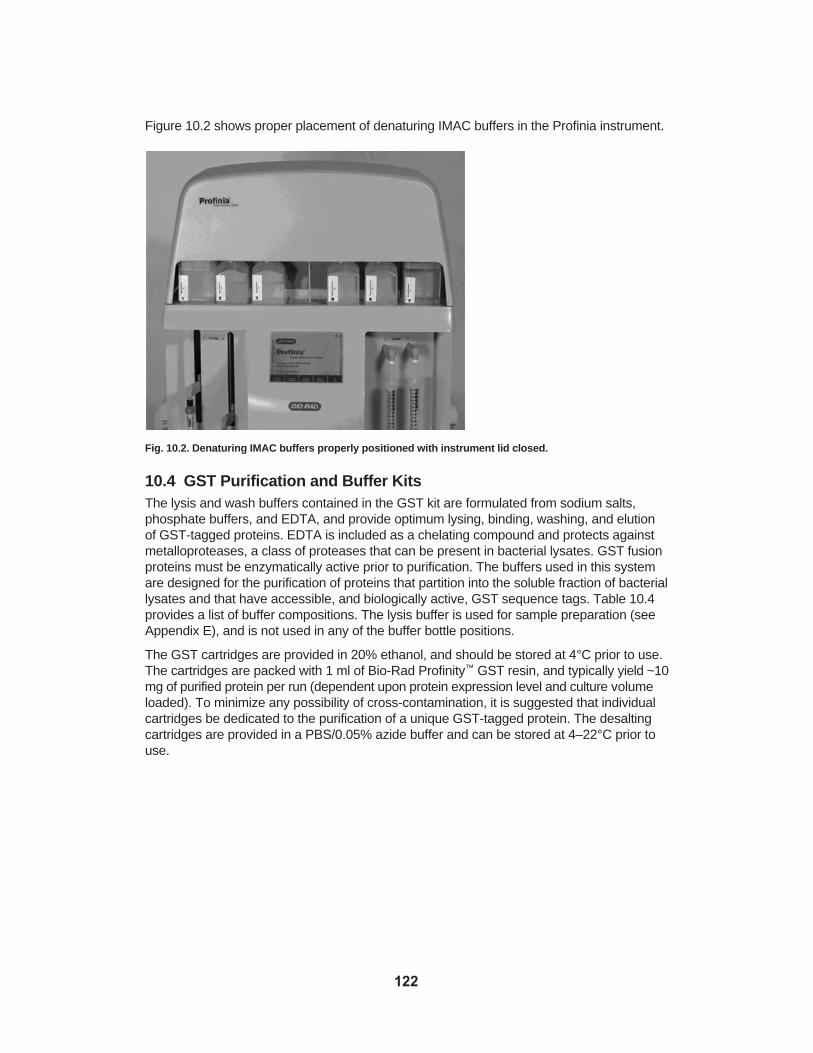
Figure 10.2 shows proper placement of denaturing IMAC buffers in the Profinia instrument.
Fig. 10.2. Denaturing IMAC buffers properly positioned with instrument lid closed.
10.4 GST Purification and Buffer KitsThe lysis and wash buffers contained in the GST kit are formulated from sodium salts,phosphate buffers, and EDTA, and provide optimum lysing, binding, washing, and elutionof GST-tagged proteins. EDTA is included as a chelating compound and protects againstmetalloproteases, a class of proteases that can be present in bacterial lysates. GST fusionproteins must be enzymatically active prior to purification. The buffers used in this systemare designed for the purification of proteins that partition into the soluble fraction of bacteriallysates and that have accessible, and biologically active, GST sequence tags. Table 10.4provides a list of buffer compositions. The lysis buffer is used for sample preparation (seeAppendix E), and is not used in any of the buffer bottle positions.
The GST cartridges are provided in 20% ethanol, and should be stored at 4°C prior to use.The cartridges are packed with 1 ml of Bio-Rad Profinity™ GST resin, and typically yield ~10mg of purified protein per run (dependent upon protein expression level and culture volumeloaded). To minimize any possibility of cross-contamination, it is suggested that individualcartridges be dedicated to the purification of a unique GST-tagged protein. The desaltingcartridges are provided in a PBS/0.05% azide buffer and can be stored at 4–22°C prior touse.
122

Table 10.4. Formulations for buffers and solutions provided in the GST kits.
Profinia Supplied Concentrated Working 1x Vol, Buffer Solution Formulation Formulation ml PositionGST lysis 2x 300 mM NaCl, 150 mM NaCl, 125 N/Abuffer 20 mM Na2HP04, 10 mM Na2HP04,
10 mM EDTA,pH 7.4 5 mM EDTA, pH 7.4GST 2x 300 mM NaCl, 150 mM NaCl, 200 1wash 20 mM Na2HP04, 10 mM Na2HP04, buffer 10 mM EDTA, pH 7.4 5 mM EDTA, pH 7.4GST 2x 40 mM glutathione, 20 mM glutathione, 100 3elution 200 mM Tris, 10 mM EDTA, 100 mM Tris, 5 mM EDTA, buffer pH 8.0 pH 8.0Desalting 5x 685 mM NaCl, 13.5 mM KCl, 137 mM NaCl, 2.7 mM KCl, 200 4buffer 21.5 mM Na2HP04, 4.3 mM Na2HP04,
40.5 mM KH2P04, pH 8.1 mM KH2P04, pH 7.47.0 (pH 7.4 upon dilution)
Cleaning 2x 1,000 mM NaCl, 100 mM Tris, 500 mM NaCl, 50 mM Tris, 125 5solution 1 pH 8.0 pH 8.0Cleaning 4x 2,000 mM NaCl, 500 mM NaCl, 125 6solution 2 400 mM NaOAc, pH 4.5 100 mM NaOAc, pH 4.5Storage 2x 4% C6H5CH2OH (benzyl 2% C6H5CH2OH (benzyl 200 7Solution alcohol) alcohol)
Figure 10.3 shows proper placement of GST buffers in the Profinia instrument.
Fig. 10.3. GST buffers properly positioned with instrument lid closed.
10.5 Desalting Buffer and Separation KitsThe buffers and solutions provided in the desalting kit consist of a PBS-based desaltingbuffer, cleaning buffers, and a storage solution. The PBS solution provides an optimumionic strength to prevent nonspecific interactions between proteins and the matrix, and is acommonly used buffer for the storage of a wide variety of proteins.
123

Note: Desalting buffers are already included in native IMAC and GST purification andbuffer kits. Optimized desalting and storage solutions for unique proteins need to be determined empirically.
The desalting solutions and cartridges can be used to remove or exchange salts, buffers,and small molecules from any protein sample. Table 10.5 provides a list of buffer compositions.
The desalting cartridges are provided in water with 0.05% sodium azide as a preservative,and can be stored between 4 and 22°C prior to use. The cartridges are packed with 10 ml of Bio-Rad P6 size exclusion resin, and typically yield ~80% or more recovery ofapplied target protein. The resin in the P6 desalting cartridges interacts minimally with proteins. When used with the cleaning buffers, different proteins can safely be applied tothe same desalting cartridge.
Table 10.5. Formulations for buffers and solutions provided in the Profinia desalting kits.
Profinia Supplied Concentrated Working 1x Vol, BufferSolution Formulation Formulation ml PositionDesalting 5x 685 mM NaCl, 13.5 mM KCl, 137 mM NaCl, 2.7 mM KCl, 200 4buffer 21.5 mM Na2HP04, 4.3 mM Na2HP04,
40.5 mM KH2P04, pH 7.0 8.1 mM KH2P04, pH 7.4(pH 7.4 upon dilution)
Cleaning 2x 1,000 mM NaCl, 100 mM Tris, 500 mM NaCl, 50 mM Tris, 125 5solution 1 pH 8.0 pH 8.0Cleaning 4x 2,000 mM NaCl, 500 mM NaCl, 125 6solution 2 400 mM NaOAc, pH 4.5 100 mM NaOAc, pH 4.5Storage 2x 4% C6H5CH2OH (benzyl 2% C6H5CH2OH (benzyl 200 7solution alcohol) alcohol)
Figure 10.4 shows proper placement of desalting buffers in the Profinia instrument.
Fig. 10.4. Desalting buffers properly positioned with instrument lid closed. Also shown, the desalting loopinstalled in the cartridge 1 position.
124

Section 11 Connecting External ComponentsFunctionality of the Profinia™ protein purification system can be enhanced by add-on components. The instrument can be connected to a pH monitor, larger buffer bottles (standard sizes with Bio-Rad methods are 125 ml and 250 ml), larger sample and fractiontubes (standard sizes with Bio-Rad methods are 15 ml and 50 ml), and the Profinia coolingaccessory.
11.1 pH MonitorThe optional pH monitor (catalog #620-0411) allows the Profinia system to monitor the pHof the fluid stream of a protein sample. This pH information is displayed on the instrument’sscreen, stored in the run data record, and can be displayed in real time on the computerscreen if the system is connected to a computer running Profinia software. Run data canalso be exported for later viewing and analysis.
The pH monitor kit (Figure 11.1) includes:
• Bio-Rad pH probe — calomel pH probe, sealed for maintenance-free operation
• Profinia pH flow cell — minimum swept volume for best response
• Tubing assembly — connects the flow cell to the instrument
• Mounting bracket and screws
• Instructions
Fig. 11.1. Profinia pH monitor kit.
Additional materials required are standard pH calibration buffers, pH 4.0 and 10.0, availablefrom laboratory supply companies.
To install the pH flow cell and probe:
1. Use the power switch to turn the instrument off and unplug the power cord.
2. Use the handles on the back of the unit to turn it so the back of the unit is facing you.
Important: Use care not to spill any fluids when turning the unit.
3. Disconnect and remove the waste bottle (right side of the instrument).
4. Remove the thumbscrews connecting the rear access panel to the instrument; thereare two thumbscrews at the top of the panel, and two near the center.
125
pH probe
Tubingassembly
pH flow cell
Mountingbracket &screws

5. Lift off the access panel by pulling it straight toward you (Figure 11.2).
Fig. 11.2. Rear view of instrument with access panel removed.
6. Locate the two holes provided for mounting the pH flow cell.
7. Install the pH flow cell bracket using two Phillips head screws (Figure 11.3).
Fig. 11.3. Bracket mounted in the correct location in the instrument fluidics area.
8. Find the tubing connecting the conductivity flow cell to the center of the outlet selectvalve. Unscrew the fitting at the outlet select valve.
126
pH flow cellmounting bracketholes and screws
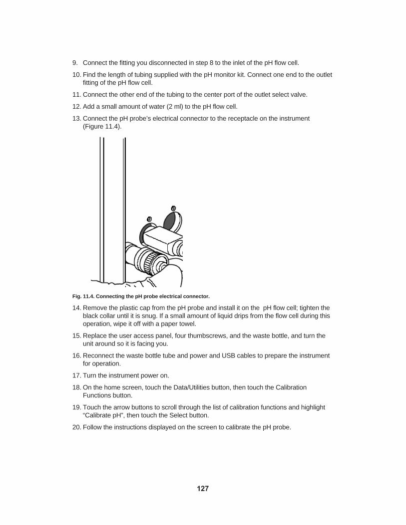
9. Connect the fitting you disconnected in step 8 to the inlet of the pH flow cell.
10. Find the length of tubing supplied with the pH monitor kit. Connect one end to the outletfitting of the pH flow cell.
11. Connect the other end of the tubing to the center port of the outlet select valve.
12. Add a small amount of water (2 ml) to the pH flow cell.
13. Connect the pH probe’s electrical connector to the receptacle on the instrument (Figure 11.4).
Fig. 11.4. Connecting the pH probe electrical connector.
14. Remove the plastic cap from the pH probe and install it on the pH flow cell; tighten theblack collar until it is snug. If a small amount of liquid drips from the flow cell during thisoperation, wipe it off with a paper towel.
15. Replace the user access panel, four thumbscrews, and the waste bottle, and turn theunit around so it is facing you.
16. Reconnect the waste bottle tube and power and USB cables to prepare the instrumentfor operation.
17. Turn the instrument power on.
18. On the home screen, touch the Data/Utilities button, then touch the CalibrationFunctions button.
19. Touch the arrow buttons to scroll through the list of calibration functions and highlight“Calibrate pH”, then touch the Select button.
20. Follow the instructions displayed on the screen to calibrate the pH probe.
127

Fig. 11.5a. Installing the flow cell. Fig. 11.5b. Connecting the electrical connector.
Fig. 11.5c. Connecting the tubing. Fig. 11.5d. Installing the pH probe.
11.2 Larger Buffer, Sample, and Fraction ContainersThe Profinia system is designed to operate with built-in components (buffer bottles andfraction and sample tubes), but can accommodate larger bottles and tubes for large-sampleruns or program methods that require buffer volumes greater than those accommodated bythe Profinia 250 ml buffer bottle.
Important: Prior to starting a method, all the externally connected reagent tubes must beprimed manually. Use the manual priming function on the Start Run screen to do this.
11.2.1 External Buffer Containers
To connect an external buffer container to the Profinia instrument, all that is required is 1/8"OD PTFE tubing (catalog #750-0603 or similar), sufficient in length to connect the externalbottle(s) to the buffer inlet port on the instrument. To use buffer bottles that do not fit in thesystem buffer bottle tray:
1. Place buffer bottle(s) to be used in your purification run next to the instrument.
2. Locate the bottom section of tubing that is connected to each buffer inlet valve.
3. Use one hand to push up on the silicone coupler, and the other to disconnect the shortpiece of tubing by pulling it off.
4. Install the longer piece of 1/8" OD PTFE tubing by pushing one end into the siliconecoupling (Figure 11.6).
128
1
2
3
4

Fig. 11.6. Installing PTFE tubing into the position 2 buffer line.
5. Place the other end of the tubing into the external buffer bottle.
Note: If connecting more than one external buffer bottle for a run, it is helpful to use stickersto label each tube with the Profinia buffer position number marked on the buffer tray.
Once the longer tubes have been installed and other standard setup procedures are complete, the system is ready for a purification run.
Note: The inlet tube must be primed before starting a run. This can be done using the manual priming function in the method Start Run screen.
11.2.2 External Sample Containers
To connect an external sample container to the Profinia instrument, all that is required isPTFE tubing, 1/8" OD, sufficient in length to connect the external container(s) to the sampleinlet port(s) on the instrument. You need a length of tubing for each port that accommodatesthe external sample containers. To use sample tubes that do not fit in the system sampleinlet tray:
1. Place external sample container(s) next to the instrument.
2. Locate the bottom section of tubing that is connected to each sample inlet valve.
3. Use one hand to push up on the silicone coupler, and the other to disconnect the tubingby pulling it off.
4. Install the 1/8" OD PTFE tubing by pushing one end into the silicone coupling.
5. Place the other end of the tubing in the external sample container.
Note: If connecting more than one external sample container for a run, it is helpful to usestickers to label each tube with the Profinia sample position number marked on the buffertray.
129
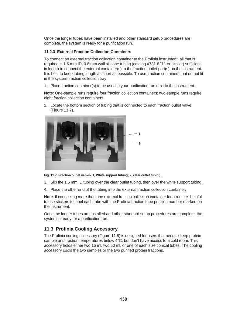
Once the longer tubes have been installed and other standard setup procedures are complete, the system is ready for a purification run.
11.2.3 External Fraction Collection Containers
To connect an external fraction collection container to the Profinia instrument, all that isrequired is 1.6 mm ID, 0.8 mm wall silicone tubing (catalog #731-8211 or similar) sufficientin length to connect the external container(s) to the fraction outlet port(s) on the instrument.It is best to keep tubing length as short as possible. To use fraction containers that do not fitin the system fraction collection tray:
1. Place fraction container(s) to be used in your purification run next to the instrument.
Note: One-sample runs require four fraction collection containers; two-sample runs requireeight fraction collection containers.
2. Locate the bottom section of tubing that is connected to each fraction outlet valve(Figure 11.7).
Fig. 11.7. Fraction outlet valves. 1, White support tubing; 2, clear outlet tubing.
3. Slip the 1.6 mm ID tubing over the clear outlet tubing, then over the white support tubing.
4. Place the other end of the tubing into the external fraction collection container.
Note: If connecting more than one external fraction collection container for a run, it is helpfulto use stickers to label each tube with the Profinia fraction tube position number marked onthe instrument.
Once the longer tubes are installed and other standard setup procedures are complete, thesystem is ready for a purification run.
11.3 Profinia Cooling AccessoryThe Profinia cooling accessory (Figure 11.8) is designed for users that need to keep proteinsample and fraction temperatures below 4°C, but don’t have access to a cold room. Thisaccessory holds either two 15 ml, two 50 ml, or one of each size conical tubes. The coolingaccessory cools the two samples or the two purified protein fractions.
130
1
2

Fig. 11.8. Profinia cooling accessory. The instrument comes with two cooling units as shown.
To install the cooling accessory on the instrument:
1. Fill the cooling accessory with water to the inside chamber fill line.
Warning: Use tap water when filling the cooling accessory with water; do not use deionizedwater because it will expand in the unit during freezing. Do not fill the cooling accessorypast the top of the vertical rib located inside the unit.
2. Chill the cooling accessory in a freezer.
3. Place the sample or fraction tubes in the cooling accessory.
4. Place the tubes and the cooling accessory on the instrument in the desired sampleand/or fraction collection position.
Fig. 11.9. Placing sample tubes in the cooling accessory on instrument sample lines (left); cooling accessory units installed in both the sample and purified protein fraction collection tube positions (right).
131

11.4 Connecting non-Bio-Rad ColumnsColumns from other suppliers can be connected to the Profinia instrument. Figure 11.10displays other commercially available affinity columns connected in cartridge position 1 onthe Profinia instrument. For instructions on how to connect non-Bio-Rad columns to theProfinia instrument, please request bulletin 5326, Chromatography Column ConnectionGuide.
Fig. 11.10. Examples of non-Bio-Rad columns connected to the Profinia instrument.
132

Section 12 The Profinia SoftwareThe Profinia software runs on a PC platform, and allows viewing and reporting of run data;it is an optional accessory to the Profinia protein purification instrument and does not con-trol instrument functions. This section contains basic instructions for operating the software.For complete software instructions, see the Profinia Software User’s Guide on the Profinia software CD.
12.1 Operating RequirementsThe following are minimum system requirements for running Profinia software:
• Operating system — Windows XP or Windows Vista
• CPU — Pentium 4 processor at 2 GHz or higher
• RAM — 512 MB minimum
• Screen resolution — 1,024 x 768
• Hard drive space — 80 GB minimum
• Other driver — CD-ROM
• USB port — 2.0
12.2 Software StructureThe default opening screen of Profinia software is divided into five main areas (Figure 12.1):
• Menu options — top portion of the screen includes pull-down menus and buttoncommands for navigating software functionality
• Directory menu — upper left window displays folders located on the computer’s internaland external drives; click on the plus symbol located next to the drive names to expanddirectory information for that drive
• File menu — lower left window displays any Profinia data files (.ofi file extension) locatedin the folder highlighted in the directory menu window
• Chromatogram window(s) — upper right section displays chromatographic data fromthe purification profile; the y-axis displays absorbance units (AU) and the x-axis displaysrun time (hh:mm). A chromatogram is displayed for each sample (up to two) purified inthe run
• Data table — lower right section displays a data table of run information and results;click on the tabs at the bottom of the screen to view data for different parameters of therun
133

Fig. 12.1. Profinia software main screen. Area 1, menu options; area 2, directory menu; area 3, file menu;area 4, chromatogram window(s); area 5, data table.
12.3 Transferring Data to Profinia SoftwareThere are two ways to transfer Profinia instrument data files to Profinia software:
• Real-time data transfer — transfer in-progress run data via USB cable connectionbetween a computer operating Profinia software and the instrument
• Portable memory device data transfer — transfer files via USB portable memorydevice at the end of a run
12.3.1 Real-Time Data Transfer
To import data into Profinia software via real-time data transfer:
1. Connect the instrument to your computer using the USB cable provided with the software.
2. Open Profinia software on your computer.
3. Make sure communication between the instrument and computer has been established.This is indicated by a “Waiting for data” message displayed at the bottom of the Profiniasoftware screen (Figure 12.2).
Fig. 12.2. “Waiting for data” message on the bottom of the Profinia software screen indicates communication between the instrument and the computer is established and a run can be started.
134
1
2
3
4
5
4. Highlight the directory in your computer to which you’d like the run data transferred.
5. Start the purification run according to the procedure outlined in section 6.6. As the runprogresses, data appears in real time in the software chromatogram(s) and data tables.At the end of the run, the completed data file will be stored in the directory highlighted instep 4.
Note: The run data filename format consists of the run name assigned by the user on theEnter Run & Sample Information screen on the instrument (see section 6.3) and an .ofi fileextension.
12.3.2 Portable Memory Device Data Transfer
After the file has been transferred from the Profinia instrument to the portable USB portablememory device (see section 9.1.1 for information on transferring run data files to a portablememory device):
1. Plug the portable memory device into any available USB port on your computer.
2. Open the folder for the USB portable memory device.
3. Choose the folder on the computer in which you would like to place the run data file, orcreate a new folder in which to store the data file. Profinia automatically creates a“Data” folder in the software system files created upon installation (for example, if youinstalled the software program in the “C: Program Files” location, there will be a “Data”folder automatically created in the same location).
4. Copy and paste or drag and drop the run file from the portable USB portable devicefolder to the desired data folder.
12.4 Viewing Run Data Files
12.4.1 Opening Files in Profinia Software
1. Open Profinia software.
2. Using the directory on the left side of the screen, locate the folder that contains thedesired run data file. All run data files contained in the selected folder will be displayedin the lower file menu portion of the screen.
3. Double-click the run data file to be viewed. The file chromatogram(s) and data tableslaunch in the right side of the screen.
135

12.4.2 Chromatogram Overview
The following run parameters are displayed in the software chromatogram (Figure 12.3):
• UV-1 — data trace from the UV-1 detector
• Pressure — data trace from the pressure monitor
• pH — data trace from the pH monitor (optional accessory)
• UV-2 — data trace from the UV-2 detector
• Cond — data trace from the conductivity monitor
• Temp — data trace from the temperature monitor
• Main Steps — indicated by a downward-facing arrow symbol that marks the time atwhich each main step occurred during the course of the run
• Fraction — indicated by “collection tube” symbol that marks the points at which collection began during the course of the run
Fig. 12.3. Run parameters displayed at the top of a Profinia software chromatogram.
12.4.3 Eliminating Run Parameters Displayed
The top of each chromatogram displays all possible run parameters. Checked boxes indicatethe parameters displayed in the chromatogram. To remove any parameter from the chromatogram, click on the box to remove the checkmark. The trace for that parameter aswell as any parameter-specific axis information will be removed from the screen.
12.4.4 Customizing Chromatogram Display Options
Customize the way information is displayed on your chromatogram by changing line colorsand widths, choosing whether UV-1 and UV-2 information is displayed on separate axes,determining the major steps that are included in the chromatogram, and whether a sound isheard at sample elution (real-time data display only).
Changing Chromatogram Background and Trace Colors
There are two categories of data for which you can customize the colors that are displayed:
• Chromatogram background — color of the entire chromatogram background
• Traces — color of each line that indicates UV, pressure, pH, conductivity, and fractioninformation from the run
To change the colors that are used to distinguish information in your chromatogram:
1. Click “Options” > “Colors” from the software main menu.
2. Click on the bubble next to the parameter to change.
3. Click the Color button located at the bottom of the list of parameters.
4. Choose from Named or System Colors, or customize a color using the screen tabs.Once a color has been selected, click the OK button to return to the ChromatogramOption screen.
Note: Changes appear on the chromatogram as you make adjustments, but won’t besaved until the entire procedure is completed.
136

5. Repeat this procedure for each data category for which you’d like to implement a colorchange. When finished, click Save to retain changes and return to the main softwarescreen, or click Close to return to the screen without implementing changes.
Fig. 12.4. Changing the color of the UV-1 trace line by selecting from the “Named” color list; it is also possible to create custom colors.
Changing Trace Line Width
To change the thickness of trace lines:
1. Click “Options” > “Trace Options” from the software main menu.
2. Use the up and down arrows located in the “Width” box next to the parameter toincrease or decrease the width of its associated trace.
Note: Changes appear on the chromatogram as you make adjustments, but won’t besaved until the entire procedure is completed.
3. Repeat this procedure for each data category for which you’d like to implement a tracewidth change. When finished, click Save to retain changes and return to the main software screen, or click Close to return to the screen without implementing changes.
Changing UV Axis Display
The software automatically generates separate axes for each UV detector. To merge UVaxis information into one y-axis:
1. Click “Options” from the software main menu.
2. Locate the “Separate Axis for UV-1 and UV-2 (Top)” and “Separate Axis for UV-1 andUV-2 (Bottom)” menu options. A checkmark next to these menu options indicates thefunction is in effect.
Note: Only two-sample runs have top and bottom chromatograms.
3. Click on the option for which you’d like to merge y-axis labels. The checkmark next tothe menu option disappears and UV-1 and UV-2 axis information displays together.
4. Repeat this procedure to separate UV-1 and UV-2 axis information.
137

Changing Major Steps Displayed
Major steps are regions between main steps such as sample load begin/end and wash-1begin/end. The following major steps are displayed on the chromatogram and indicated bydownward-facing arrows:
• Sample load
• Wash-1
• Wash-2
• Elute affinity
• Elute desalting
To add highlights to the screen indicating the time during which when these steps occurred:
1. Click “Options” > “Major Steps”.
2. Click the box of the main step you’d like highlighted.
Note: Changes appear on the chromatogram as you make adjustments, but won’t besaved until the entire procedure is completed.
3. Repeat this procedure for each major step for which you’d like to implement a changein display.
4. Adjust the transparency of the highlights using the up and down arrows next to theTransparency command.
5. When finished, click Save to retain changes and return to the main software screen, orclick Close to return to the screen without implementing changes.
Changing Chromatogram Default Options
The following default information can be adjusted to change the way all chromatogramsdisplay:
• Trace visibility — turn off trace displays for checked items: UV-1, UV-2, Pressure,Conductivity, pH, Temperature, Fraction, and Main Steps
Note: UV-1 and UV-2 are not applicable for all methods and will be turned off automatically.
• UI configuration — remove file browsing or data table windows from the main screen
• X-axis — choose whether the x-axis displays data related to “Time” or “Volume”
• Standard report y-scales — choose whether the y-axis displays “Y-axes according toSample 1”, “Y-axes according to Sample 2”, or “Y-axes as is”
To adjust default information:
1. Click “Options” > “Defaults”.
2. Click the items you’d like to add or remove from the default displays.
Note: Changes appear on the chromatogram as you make adjustments, but won’t besaved until the entire procedure is completed.
3. When finished, click Save to retain changes and return to the main software screen, orclick Close to return to the screen without implementing changes.
138

12.5 ReportsProfinia software enables users to create and print reports for use in presentations or labo-ratory recordkeeping.
12.5.1 Standard Reports
Standard reports display:
• Method and run information — method name, run name, run start (day, date, andtime), run duration (hh:mm:ss), run data file (directory and file name), user name, FW(firmware) version, and instrument serial number
• Chromatogram(s) — sample 1 and sample 2 (two-sample runs) as they appear on thescreen. Adjust the zoom and other settings to the image you want, then create thereport to include the chromatogram as you have specified
• Data tables — default displays sample-related data including concentration, elutiontime, load volume, flow rates, and wash times for the run
• Footer — default information is the day, date, and time the report was printed
To create a standard report:
1. Click “Reports”, then highlight “Standard Report”.
2. Choose to “Print to Default Printer” or “Preview”.
This procedure can also be accomplished by clicking the Print Std Reports button locatedat the top of the software screen. You cannot preview a report before printing it using thisshortcut command.
12.5.2 Custom Reports
The following parameters can be adjusted to customize reports:
• Chromatogram(s) size — choose Small, Medium, Large, or Custom; custom sizes arecreated using the up and down arrows to specify chromatogram height and width
• Information to include — select each type of information to include in the report; alsouse this list to specify the order in which information is to appear in the report
• Select a report — choose any previously customized report
• Add report comments — insert any details you’d like included in the report
• Name your custom report — create a name for your report to simplify future identification and retrieval
To create a custom report:
1. Click “Reports” > “Custom Reports” to open the Define or Select a Custom Reportscreen.
2. Select the chromatogram size and information to include in the report by clicking on thebubbles or boxes next to the list of options.
3. Change the order of information included in the report by highlighting an option in the“Information to Include” list and using the up and down arrows to the right to move theselection. The order of the information listed in the menu is the order in which it appearson the report.
4. Type any desired notes into the “Add Report Comments” box.
139

5. Type a name for the report into the “Name your custom report” text line.
6. Click the Save button to save the customized report version. The name of the reportappears in the “Select a Report” list.
7. If desired, click the Make Favorite button to identify this custom report as the preferredversion. For future run data files, simply click the Print Favorite button located at the topof the screen to print a report with these options selected.
8. Click Preview to see how the report will print, Print to print the report, or Close to closethe window and return to the software’s main screen.
12.6 Exporting ChromatogramsProfinia chromatogram images can be exported in many different image files, including .jpgand .tif file formats. To export chromatograms:
1. Click “File” > “Export Chromatograms”.
2. Select the desired image file format.
3. Select to “Copy to Clipboard” for immediate use, or “Save to File” for future use.
12.7 Exporting Data FilesProfinia run data files can be exported in either text or Excel file format. To export run data:
1. Click “File” > “Export Run Data” to open the Export Run Data window.
2. If a run is currently open in Profinia software, that filename appears as the data toexport. To export a different data file, click the Browse button to navigate computerdrives and directories.
3. Select the information to be exported with the file by marking the bubble or boxes nextto each option.
4. Choose “Text” or “Excel” file format from the “Select File Format” pull-down menu.
5. Choose whether you’d like the data deliminated by tab, comma, space, or colon usingthe “Select Deliminator” pull-down menu.
6. Click Save to proceed with exporting data with the options selected or Close to abandonthe procedure and return to the main screen.
7. If proceeding with data export, the Save As window opens. Select a folder and filename for the data export, then click Save to finish data export or Cancel to return to theExport Run Data screen.
12.8 Help InformationYou can find complete instructions on software functionality in the Profinia Software User’sGuide, or use the software Help screen for more information on how to perform software procedures:
1. Click “Help” from the software pull-down menu.
2. Click “Contents and Index” to retrieve a list of help topics or to search the help index, or“About” to retrieve information about the software version.
140

Section 13 Care and MaintenanceProper care and maintenance of Profinia™ system parts help keep the instrument operatingat optimum performance levels.
13.1 Cleaning the InstrumentThe Profinia instrument automatically flushes system lines at the end of each purificationrun. To keep the system clean, there are several automated cleaning and storage procedures:
• Daily cleaning — buffer, sample, and fraction line cleaning
• Weekly cleaning — system NaOH and ethanol washes
• Storage
The procedures are selected from the Diag/Maint Functions menu, which is accessible viathe Data/Utilities menu. The procedures outlined below are designed to use water, ethanol,or sodium hydroxide (NaOH). Other cleaning solutions, such as 0.5 M hydrochloric acid(HCl), or 6 M guanidine HCl, may also be used. When using multiple cleaning solutions (forexample, 0.1 M NaOH followed by 0.5 M HCl), flush the system with water between stepsto prevent interactions between the cleaning chemicals.
Before running the cleaning procedures, remove the cartridges and connect the cartridge inletand outlet fittings by turning the plastic collars clockwise. Remove all fraction tubes andplace the cleaning tray in the fraction collection area. To run each cleaning procedure:
1. Touch the Data/Utilities button, then the Diag/Maint Functions button on the lower toolbar to retrieve the menu for cleaning functions.
2. On the Diag/Maint Functions screen, touch the up and down arrows to scroll throughthe list of functions and highlight the desired cleaning procedure.
3. Touch Select, then follow the touch screen instructions.
13.1.1 Daily Cleaning
When finished using the system for the day, perform buffer, sample, and fraction line cleaning procedures as described in section 13.1.4.
13.1.2 Weekly Cleaning
Once a week, run the system NaOH wash, then the system ethanol wash as described insection 13.1.4.
13.1.3 Storage
If the system will not be used for more than a week:
1. Run the system NaOH wash, then the system ethanol wash as described in section13.1.4.
2. Empty the diluent and waste bottles.
3. Cap the ends of the buffer and sample inlet tubes and fraction outlet tubes with thecaps the instrument was shipped with (replacement Catalog #620-0444) to prevent theentry of dust or foreign objects.
141

4. If system power will be left on, go to the Manual Operation screen (Data/Utilities >Diag/Maint Functions > Manual Operation) and turn the lamp off, using the ToggleLamp button.
Note: When the Profinia instrument is switched on, the UV lamp does not start until amethod starts. The UV lamp shuts off automatically one hour after a method is finished. Ifyou use the Toggle Lamp button to switch the lamp on, it will stay on until the machine ispowered down or until you toggle the lamp off. The one hour shutoff does not functionwhen the lamp is turned on manually.
13.1.4 System Cleaning Procedures
Cleaning Sample Lines
Use this procedure to clean the lines between the inlet select valve and the sample tubes:
1. Remove all sample tubes from the instrument.
2. Fill conical tubes with 25 ml of deionized water and place them in sample positions 1and 2.
3. Fill a buffer bottle with 100 ml of 20% ethanol and place it in buffer position 8.
4. Touch the Start button. A progress bar displays, tracking the duration of the procedure.
Cleaning Fraction Lines
Use this procedure to clean the lines between the outlet select valve and the fraction tubes:
1. Remove all fraction tubes from the instrument.
2. Place the cleaning tray in the fraction collection area.
3. Place a bottle with 100 ml of 20% ethanol in buffer position 8.
4. Touch the Start button. A progress bar displays, tracking the duration of the procedure.
Cleaning Buffer Lines
Use this procedure to clean the lines between the buffer containers and the inlet selectvalve:
1. Fill seven buffer bottles with 50 ml of deionized water each, and place them in bufferpositions 1 through 7.
2. Fill one buffer bottle with 100 ml of 20% ethanol and place it in buffer position 8.
3. Touch the Start button. A progress bar displays, tracking the duration of the procedure.
System Ethanol Wash
Use this procedure to pump ethanol solution through the system:
1. Remove both cartridges from the system, and connect the inlet and outlet cartridge fittings together.
2. Fill seven buffer bottles with 50 ml of 20% ethanol each, and place them in buffer positions 1 through 7.
3. Fill one buffer bottle with 100 ml of 20% ethanol and place it in buffer position 8.
4. Fill two conical tubes with 25 ml of 20% ethanol each, and place them in sample positions 1 and 2.
142

5. Place the cleaning tray in the fraction collection area.
6. Touch the Start button. A progress bar displays, tracking the duration of the procedure.
Cleaning Inlet and Outlet Lines
Use this procedure to clean all buffer and sample inlets and fraction outlets:
1. Fill diluent bottle with deionized water.
2. Fill seven buffer bottles with 50 ml of deionized water each, and place them in bufferpositions 1 through 7.
3. Fill one buffer bottle with 100 ml of 20% ethanol and place it in buffer position 8.
4. Fill two conical tubes with 25 ml of deionized water each, and place them in samplepositions 1 and 2.
5. Place the cleaning tray in the fraction collection area.
6. Touch the Start button. A progress bar displays, tracking the duration of the procedure.
Cleaning Pump Check Valves
Use this procedure to pump NaOH solution through the pump and clean the piston andcheck valves:
1. Fill the diluent bottle with deionized water.
2. Fill one buffer bottle with 50 ml of NaOH solution (0.1 to 0.5 M) and place it in bufferposition 8.
3. Touch the Start button. A progress bar displays, tracking the duration of the procedure.
System NaOH Wash
Use this procedure to wash the system (except the buffer inlets) with NaOH solution:
1. Fill the diluent bottle with deionized water.
2. Fill one buffer bottle with 50 ml of NaOH solution (0.1 to 0.5 M) and place it in bufferposition 8.
3. Remove both cartridges from the system, and connect the inlet and outlet cartridge fittings together.
4. Touch the Start button. A progress bar displays, tracking the duration of the procedure.
13.1.5 Cleaning Touch Screen
To clean the system touch screen:
1. Apply a neutral pH cleaner, such as ethanol or 3% or less isopropyl alcohol, to a soft,lint-free cloth.
Note: Do not apply cleaning solution directly to the surface of the touch screen.
2. Wipe the touch screen gently with the cloth without allowing fluid or compressed air toenter the small 1 mm vent hole along the edge of the touch screen.
Warning: Never use acidic or alkaline cleaners or organic chemicals, such as ammonia,phosphates, ethylene glycol, paint thinner, acetone, toluene, xylene, propyl alcohol, orkerosene to clean the Profinia touch screen.
143

13.2 MaintenanceRegular maintenance helps keep the system performing optimally. Figure 13.1 is a diagramof the instrument’s main parts and connections.
Fig. 13.1. Schematic diagram of the Profinia system.
The following internal components require regular maintenance and may need to berepaired or replaced occasionally (for a checklist of annual maintenance procedures, seeAppendix G):
• Pump check valves
• Pump seals
• UV monitor lamp
• UV monitor flow cells
• Buffer and sample inlet tubes
• Tubing and fittings
• Inline filter
144

Use the following procedure to access all internal components, then locate the part-specificprocedure for servicing or replacing the hardware in the sections that follow:
1. Turn instrument power off and unplug the power cord.
2. Turn the instrument around so the rear of the instrument is facing you.
Important: Use care not to spill any fluids when turning the unit.
3. Unplug the USB cable if connected to the instrument.
4. Disconnect the waste tube where it threads into the rear of the unit (right side of theinstrument) and remove the waste bottle; set it aside.
5. The fluidics access panel is on the right side, held in place by four thumbscrews.Remove the thumbscrews connecting the rear access panel to the instrument; thereare two screws located at the top of the panel and two near the center. Do not removethe electronics access panel, held in place by Phillips head screws.
6. Lift off the access panel by pulling it straight toward you (Figure 13.2). Set the accesspanel and thumbscrews aside.
Fig. 13.2. Rear view of instrument with access panel removed.
13.2.1 Pump Check Valves
The Profinia system automatically cleans the flow path after every run, so the check valvesshould only require service during preventive maintenance. If pump flow rates are not asexpected or sample volumes are too small, the check valves may not be working properly.
The system uses two different types of check valves:
Disk check valve — inlet (two valves on the bottom of the pump body)
Button check valve — outlet (two valves on the top of the pump body)
Removal, inspection, cleaning, and replacement procedures for both types of check valvesare similar, but not identical. Materials required to service the check valves are:
145
Check valves
Pumpassembly
UV monitorassembly
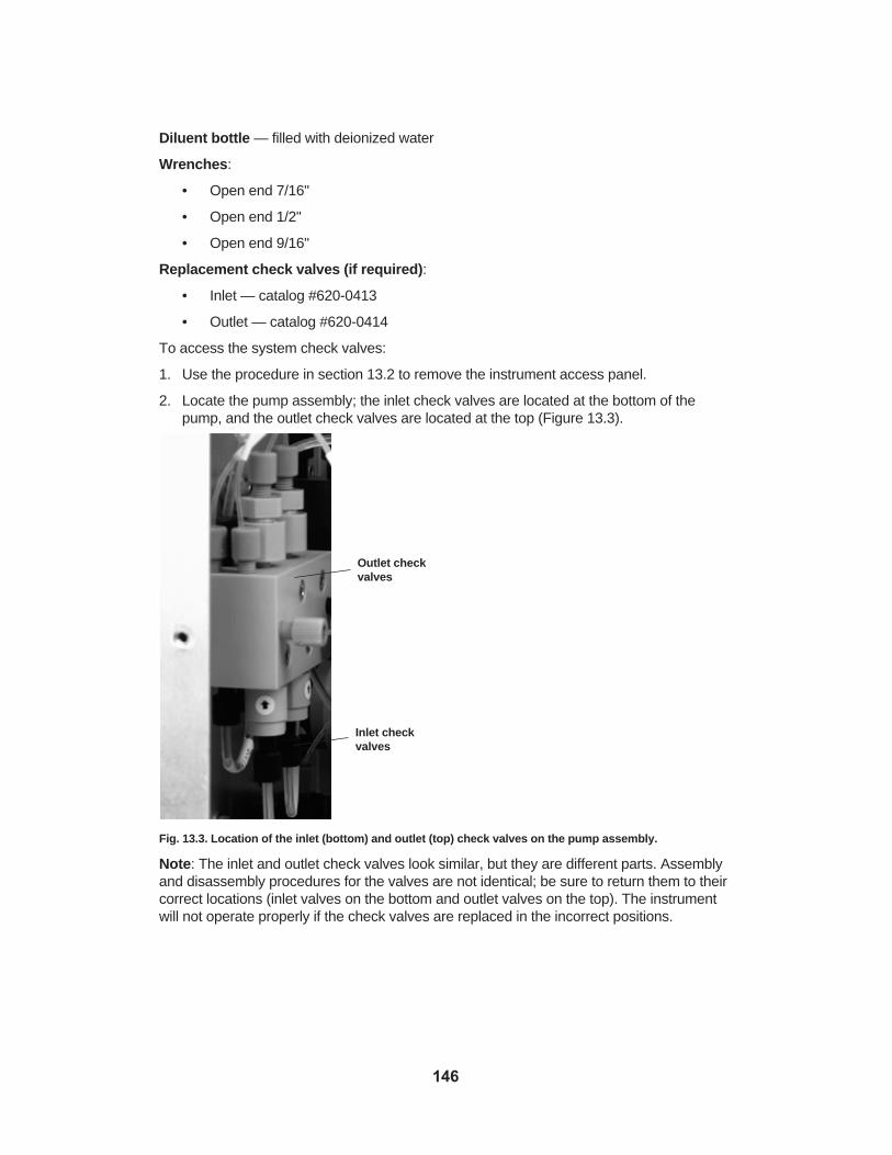
Diluent bottle — filled with deionized water
Wrenches:
• Open end 7/16"
• Open end 1/2"
• Open end 9/16"
Replacement check valves (if required):
• Inlet — catalog #620-0413
• Outlet — catalog #620-0414
To access the system check valves:
1. Use the procedure in section 13.2 to remove the instrument access panel.
2. Locate the pump assembly; the inlet check valves are located at the bottom of thepump, and the outlet check valves are located at the top (Figure 13.3).
Fig. 13.3. Location of the inlet (bottom) and outlet (top) check valves on the pump assembly.
Note: The inlet and outlet check valves look similar, but they are different parts. Assemblyand disassembly procedures for the valves are not identical; be sure to return them to theircorrect locations (inlet valves on the bottom and outlet valves on the top). The instrumentwill not operate properly if the check valves are replaced in the incorrect positions.
146
Outlet checkvalves
Inlet checkvalves

Cleaning and Replacing Inlet (Bottom) Check Valves
Fig. 13.4. Diagram of the inlet check valve.
To clean or replace the inlet check valve:
1. Remove the two tubing fittings from the bottom of the inlet flow cell.
2. Using your fingers or a 9/16" open-end wrench, unscrew the inlet flow cells from thepump body.
3. Hold the check valve body with a 9/16" open-end wrench, and loosen the threadedinsert with a ½" open-end wrench.
4. Unscrew the insert (male threaded part) from the valve body (female threaded part).Note the black rubber disk on the insert, and look into the cavity of the valve body; youwill see a tan-colored plastic disk. This disk has a groove machined into one side (theside facing you) and three small, drilled holes.
5. Turn the check valve body over and tap it on the benchtop to remove the plastic disk.
6. Carefully pry the rubber disk from the insert.
7. Rinse the check valve parts thoroughly in water and examine for damage; replace ifdamaged.
8. Replace the plastic disk in the check valve body, with the groove facing toward you.
9. Replace the rubber disk in the threaded insert — it is the same on both sides.
10. Thread the check valve insert into the check valve body and tighten, using the twowrenches as described in step 3 above.
Note: Do not overtighten the insert.
11. Thread the assembled check valve into the pump body, and tighten with a 9/16" open-end wrench; do not overtighten.
12. Reconnect the tubes and fittings to the top of the check valves.
147

Cleaning and Replacing Outlet (Top) Check Valves
Fig. 13.5. Diagram of the outlet check valve.
To clean or replace the outlet check valve:
1. Remove the tubing fittings from the top of the outlet check valve.
2. Using your fingers or a 9/16" open-end wrench, unscrew the outlet check valve from thepump body.
3. Hold the check valve body with a 9/16" open-end wrench, and loosen the threadedinsert with a 7/16" open-end wrench.
4. Unscrew the threaded insert from the valve body. The insert has a concave surfacewith a hole in it. Set the insert aside in a safe place.
5. Look into the cavity of the check valve body; you will see a tan-colored disk with a rubber “button” facing toward you. Turn the check valve body over and tap it on thebenchtop to remove the plastic disk and button from the valve body.
6. Gently pull the black button from the disk, using your fingertips.
7. Examine parts for damage; replace the check valve if necessary.
8. Using your fingers, gently replace the rubber button in the plastic disk. Take care tocenter the head in the disk. The plastic disk is the same on both sides.
9. Replace the disk in the check valve body, with the black rubber button toward you.
10. Thread the insert into the check valve body and tighten, using the two wrenches asdescribed in step 3 above.
Note: Do not overtighten the insert.
11. Thread the assembled check valve into the pump body, and tighten with a 9/16" open-end wrench.
12. Reconnect the tubing to the check valves.
148
Note: Do not overtighten the fittings.
Finishing Pump Check Valve Maintenance Procedures
When finished with check valve cleaning or replacement procedures:
1. Replace the access panel. It is best to thread all four thumbscrews loosely into theinstrument body, then tighten.
2. Reconnect the power cord and tubing.
3. Replace the waste bottle and reconnect the waste tube to the instrument.
4. Turn the unit around so the front is facing outward.
13.2.2 Pump Seals
The Profinia system automatically cleans the flow path after every run, including the areabehind the pump seals. The Profinia pump has four seals, two main seals located in thepump body, and two piston guide seals located in the piston guides. Pump seals do notnormally require replacement, except during periodic preventative maintenance. If flowrates are not as expected or sample volumes are too small, the pump seals may be leaking.The Profinia pump seals are located in the instrument cabinet, inside the pump assembly.Materials required to clean or replace the pump seals:
• Pump seal kit — catalog #620-0412, includes four pump seals, pump seal tool, andinstruction sheet
• 9/64" Allen wrench
• Wrench for tubing fittings
• Profinia 125 ml bottle — filled with 100 ml of 50% alcohol (methanol, ethanol, or isopropanol)
• Shallow tray and alcohol — for soaking pump parts
To clean or replace the system pump seals:
1. Use the procedure in section 13.2 to remove the instrument access panel.
2. Locate the pump head assembly.
3. Use your fingers or the tubing wrench to remove the 1/8" inlet tube from the front of thepump body (Figure 13.6).
149

Fig. 13.6. Removing the inlet tube from the pump assembly.
4. Use your fingers to remove the 1/16" outlet tube from the front of the pump body; youmay leave the tubes in place on the top and bottom of the valve body.
5. Use a standard 9/64" Allen wrench to remove the four screws that hold the pump headto the drive assembly (Figure 13.7).
Fig. 13.7. Removing the pump screws.
6. Pull the pump head away gently (Figure 13.8); the pump wash tubing will still be connected.
150
Inlet tube connection
Outlet tube connection
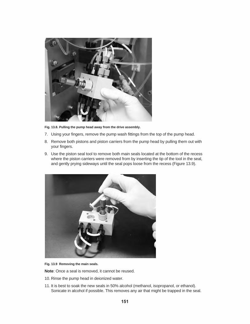
Fig. 13.8. Pulling the pump head away from the drive assembly.
7. Using your fingers, remove the pump wash fittings from the top of the pump head.
8. Remove both pistons and piston carriers from the pump head by pulling them out withyour fingers.
9. Use the piston seal tool to remove both main seals located at the bottom of the recesswhere the piston carriers were removed from by inserting the tip of the tool in the seal,and gently prying sideways until the seal pops loose from the recess (Figure 13.9).
Fig. 13.9 Removing the main seals.
Note: Once a seal is removed, it cannot be reused.
10. Rinse the pump head in deionized water.
11. It is best to soak the new seals in 50% alcohol (methanol, isopropanol, or ethanol).Sonicate in alcohol if possible. This removes any air that might be trapped in the seal.
151

12. Press the new seals into the recesses in the pump body with your fingers, then use thepiston seal tool to snap them into place. Soak the pump body in 50% alcohol, sonicatein alcohol if possible to remove any trapped air.
13. To replace the piston carrier seals, pull the pistons from the piston carriers, and washall parts with deionized water.
Fig. 13.10. Piston and piston carrier.
14. Use the piston seal tool to remove both piston carrier seals from the piston guide byinserting the tip of the tool in the seal and gently prying sideways until the seal popsloose from the recess (Figure 13.11).
Note: Each piston guide has seals at one end; these are identical to the main seals.
Fig. 13.11. Removing the piston from the piston carrier (left); and removing the piston carrier seal, usingthe piston seal tool (right).
15. Rinse the piston carrier in water, and press the new seal into place with your finger. Donot use the seal tool to install the new seal.
16. Reassemble the pistons, springs, and carriers.
17. Push the piston carriers into the pump head recess.
Note: The flats on the piston carriers must be straight up and down (Figure 13.12).
16. Wipe off the four screws and place a small amount of Vaseline or stopcock grease onthe last 1/8" of the screws. Reconnect the piston wash tubing to the top of the pumphead (2 fittings).
17. Place the screws in the pump head, and put the pump head back in the hole in the carrier. If you have trouble getting the pump head inserted, check to see that the flatson the guides align with the flats on the carrier assembly (Figure 13.12).
152

Fig. 13.12. Align the flat side of the guides with the carrier assembly recess (tubing removed for clarity).
18. Use the 9/64" Allen wrench to tighten the screws. Start the inside screws first, alternatingbetween screws until they are finger-tight, then install the outside screws and tighten allfour.
19. Connect the 1/8" inlet tube to the pump head, and tighten the fitting with the fittingwrench; do not overtighten the fitting.
20. Connect the 1/16" outlet tube to the pump head, and tighten the fitting with the fittingwrench; do not overtighten the fitting.
21. Connect the 1/8" pump seal wash tubes to the top of the pump body.
22. Replace the access cover, reconnect the power cord and tubing, and turn the unitaround to face you.
23. Turn the instrument power on.
24. Place a bottle of 20% ethanol in buffer position 8.
25. Touch the Data/Utilities button on the system home screen.
26. Touch the Diag/Maint Functions button.
27. Touch the up and down arrows to select “System Ethanol Wash”, then press the Start button. When the ethanol wash is complete, the system returns to the Diag/MaintFunctions screen.
28. Check the pump flow rate after changing piston seals (see section 9.2.2).
13.2.3 UV Monitor Lamp
When the UV lamp has passed its service life, it must be replaced. The most commonsymptom of an expired lamp is a noisy UV baseline. Use the UV monitor utility outlinedbelow to check the lamp intensity.
Checking the UV Lamp Intensity
The UV monitor measures absorbance by comparing a reference voltage from a detectorthat looks directly at the UV lamp, with a sample voltage from a detector that looks through
153
Flat side ofguides
Carrierassemblyrecess

the UV monitor cuvette. If the reference voltage is less than 0.05 volts, the lamp intensity islow and the lamp should be replaced. If the sample voltage is less than 65% of the referencevoltage, the flow cell may be dirty. Either of these conditions may cause an unstable UVbaseline.
To check voltage:
1. Switch on power to the Profinia instrument.
2. From the system home screen, touch the Data/Utilities button.
3. Touch the Diag/Maint Functions button.
4. Select the Manual Operation button.
5. Touch the “Toggle Lamp” button, at the bottom of the screen. The “lamp” icon shouldappear at the upper left hand corner of the display.
6. Wait 10 minutes for the lamp to warm up.
7. The Sample and Reference values will be displayed in the upper left corner of theManual Operation of hardware screen.
Replacing the UV Monitor Lamp
Safety warnings:
• Do not remove the UV lamp when the Profinia instrument is turned on; the UV light caninjure your eyes or skin
• The UV lamp gets hot during operation. Allow 15 min to cool before touching the lampassembly to avoid burns
• Do not touch the glass surface of the lamp. If this happens, clean with methanol and aclean cloth and allow it to dry before installing
• The lamp contains a small amount of mercury vapor — dispose of the lamp in accordancewith local regulations. Do not break or incinerate the lamp
The Profinia instrument’s UV lamp is located inside the instrument cabinet. The Profinia UVlamp replacement kit (catalog #620-0406) is required to replace the lamp. To replace theProfinia UV lamp:
1. Use the procedure in section 13.2 to remove the instrument access panel.
2. Locate the UV monitor assembly (Figure 13.13).
154

Fig. 13.13. UV monitor assembly.
3. Follow the lamp’s power cable to the metal panel, and unplug it (Figure 13.14).
Note: Depress the locking tab before pulling the connector out.
Fig. 13.14. Unplugging the UV lamp power cord.
4. Reach behind the black UV monitor assembly, and remove the two screws holding thelamp assembly using the 9/64" Allen wrench provided with the new lamp. Pull the lampcarrier and filter holder gently from the UV monitor body (Figure 13.15). Set the filterholder and screws aside in a safe place.
155
UV monitor assembly

Fig. 13.15. Removing UV lamp and filter carrier.
5. Using the 5/64" Allen wrench provided with the new lamp, remove the set screw holdingthe UV lamp in place (Figure 13.16).
Fig. 13.16. Removing the replacement UV lamp set screw.
6. Slide the UV lamp out of its carrier (Figure 13.17).
156

Fig. 13.17. Sliding the replacement UV lamp out of the carrier.
7. Remove the new UV lamp from its package. Note the round window for the UV light(Figure 13.18), and the flat for the set screw.
Fig. 13.18. Lamp with UV light window and flat for set screw.
Note: Use care not to touch the glass lamp; if this happens, clean the fingerprints from thelamp with alcohol.
8. Slide the new UV lamp into the lamp carrier, and align the hole in the lamp with the window in the carrier.
9. Using the 5/64" Allen wrench, tighten the set screw that holds the lamp in place.
10. Find the filter carrier; place this on top of the UV lamp carrier with the silver side of thefilter facing toward the lamp. Align the mounting holes in the filter carrier with the mounting holes in the lamp carrier (Figure 13.19).
157
Flat for set screw
UV lightwindow

Fig. 13.19. Filter carrier and UV lamp carrier.
11. Place the lamp and filter carriers on the UV module body and secure with the screwsusing the 9/64" Allen wrench provided with the new lamp.
12. Plug the lamp’s cord into its receptacle.
13. Replace the access panel and waste bottle, reconnect the power cord, and turn the unitaround to face you. The system is now ready to operate.
13.2.4 UV Monitor Flow Cells
The Profinia system automatically cleans the flow path after every run, so the flow cells donot generally require service. If the flow cells should become dirty or clogged, the mostcommon symptom is a noisy UV baseline. To check the flow cells, check the UV signal andreference voltages, as described in section 13.2.3. With the flow cell flushed with cleanwater, the sample voltage should be at least 65% of the reference voltage.
Removing and Replacing the UV Monitor Flow Cells
The Profinia UV flow cells are located inside the instrument cabinet, in the UV monitorassembly (Figure 13.13). To inspect or replace the flow cell:
1. Use the procedure in section 13.2 to remove the instrument access panel.
2. Locate the UV monitor assembly.
3. Remove the two tubing fittings from the top of the flow cells; mark them so they can bereconnected to the same flow cell (Figure 13.20).
158
UV lightwindow
SecuringScrew
Holes forSecuringScrew
Filter-ShinySide FacesUV Lamp

Fig. 13.20. Removing the two tubing fittings from the top of the flow cells; follow this procedure for eachflow cell.
4. Using a 9/64" Allen wrench, remove the two Allen head screws holding the UV monitorassembly to its bracket.
5. Turn the UV monitor on its side and remove the two fittings from the bottom (Figure 13.21);mark these so they can be reconnected to the proper flow cell.
Fig. 13.21. Removing the two bottom fittings of the flow cells.
6. Temporarily replace the Allen screws holding the UV monitor assembly to the bracket;do not allow the monitor assembly to hang from the tubing.
7. Remove the two screws holding the flow cell assembly using a small flat-blade screwdriver (Figure 13.22).
159

Fig. 13.22. Removing one of two screws holding the flow cell assembly in place.
8. Gently pull the flow cell assembly from its recess.
9. Look through the light passages (Figure 13.23) to inspect the flow cell; there should beno debris or obstruction.
Fig. 13.23. Flow cell assembly light passages.
10. Reinstall the flow cell assembly using a small flat-blade screwdriver.
11. Remove the UV monitor assembly from its bracket and reconnect the tubing bottom ofthe flow cell assembly. Reattach the UV monitor assembly to its bracket and tighten thescrews.
12. Reattach the two tubing fittings to the top of the UV flow cell.
13. Replace the access panel and effluent bottle, reconnect the power cord, and turn theunit around to face you.
160
Light passages

14. Turn on the unit and wait 5 min.
15. Check the sample and reference voltages, as described above.
13.2.5 Buffer and Sample Inlet Tubes
If the buffer or sample inlet tubes become worn or damaged, replace them with 1/8" ODTefzel tubing. Precut pieces of tubing are available (catalog #620-0405, Profinia sipper tubereplacement kit). You may also use tubing from a roll. Cut this tubing to 13.46 cm (5.3")long, and straighten it; heat it with a hair dryer if straightening is difficult. Pull the existingtubing from the silicone tubing coupler and replace with the new tubing.
13.2.6 Tubings and Fittings
Under normal circumstances, the internal tubing and fittings for the Profinia system shouldlast indefinitely; they are protected from damage by the instrument’s cabinet and the system’sautomatic cleaning functions. Should the tubing require replacement, however, you mayorder the Profinia instrument tubing kit (catalog #620-0415), which contains tubing and fittings. It is important that the replacement tubing is the same diameter as the original, andthe length must be within ±3 mm, because method programming is based on the volume ofthe tubing.
You may also make a replacement tube from bulk tubing and fittings. Tubing fittings are ¼-28 flat bottom, using lock rings and ferrules to make a seal. The small tubing is 1/16"Tefzel (Bio-Rad catalog #750-0602). Fittings for the 1/16" tubing are nut/ferrule/lock ringsets (catalog #750-0554). The large tubing is 1/8" Tefzel (Bio-Rad catalog #750-0603).Fittings for the 1/8" tubing are nut/ferrule/lock ring sets (catalog #750-0553).
To make a replacement tube:
Note where each end of the tubing connects (Table 13.1). Refer to the diagram on theinside of the fluidic access panel or to the diagram below (Figure 13.24) to find the connection inlets and outlets.
161

Table 13.1. Diameters and lengths required for Profinia system tubing connections.
System Connection System Label Tubing OD, Tubing Inches Length,
InchesBuffer bottle to inlet select valve port B1 to ISV 1; B2 to ISV 2; 1/8 21
B3 to ISV 3; B4 to ISV 4; B5 to ISV 5; B6 to ISV 6; B7 to ISV 7; B8 to ISV 8
Inlet select valve common to proportioning ISV Com to PV (NC) 1/8 8valve NC portDiluent bottle inlet to proportioning valve Water to PV (NO) 1/8 17NO portProportioning valve common to inline filter PV (COM) to PUMP IN 1/8 12Pump inlet tee (in pump block) to inlet check Pump in to check VLV 1/8 5valve (below pump block), 2 eachPump outlet tee (in pump block) to inlet check Pump out to check VLV 1/16 5valve (above pump block), 2 eachPump outlet to pressure sensor inlet Pump out to pressure 1/16 8Pump wash loop (top of pump block, PWash loop 1/8 4near sheet metal)Pump wash outlet to waste tee (bottom PWash out to waste 1/8 8pump block)Inline filter outlet (above buffer bottles) to Filter out to pump in 1/8 18pump inletColumn valve 1 port 2 to pump wash in CV1 P2 to PWash in 1/8 8(bottom pump block)Pressure sensor to column valve 1 common Pressure to CV1 COM 1/16 8(center) portColumn 1 tee to UV monitor 1 flow cell Tee to UV1 IN 1/16 8(below UV monitor)UV monitor 1 flow cell outlet (above UV UV1 to CV2 COM 1/16 8monitor) to column valve 2 common (center) portColumn valve 2 port 5 to column valve 2 tee CV2 P5 to tee 1/16 5UV monitor 2 flow cell outlet to column UV2 out to tee 1/16 5valve 2 teeColumn 2 tee to conductivity monitor inlet Tee to COND IN 1/16 5(or pH flow cell inlet)(Optional) pH flow cell to outlet selector valve pH to OSV 1/16 6common (center) portSample inlet short 1/8" tube with air sensor S1 or S2 1/8 2.5(inside electronics cabinet)Sample inlet 1/16" tube from union (inside S1 to ISV P9; S2 to ISV P10 1/16 16electronics cabinet) to inlet select valveColumn valve 1 port 5 to column 1 tee CV1 P6 to COL1 IN 1/16 9Column valve 1 port 6 to column 2 Inlet CV2 P6 to COL2 IN 1/16 6Column 1 out to column 1 tee COL1 out to TEE 1/16 27Column 1 tee outlet to UV monitor flow cell 1 COL1 TEE to UV1 IN 1/16 27Column 2 outlet to UV monitor 2 inlet COL2 out to UV2 IN 1/16 9(under UV monitor)Waste manifold to waste outlet Manifold to out 1/8 12
162

System Connection System Label Tubing OD, Tubing Inches Length,
InchesOutlet select valve port 10 to waste manifold OSV P10 to waste 1/8 8Column valve 2 port 4 to waste manifold CV2 P4 to waste 1/8 8Column valve 1 port 1 to waste CV1 P1 to waste 1/8 9Conductivity monitor out to outlet select valve COND out to OSV COM 1/16 8common (center) portOutlet select valve port 9 to fraction collector OSV P9 to FC 1/16 18Outlet select valve ports 1–3 to fraction tube OSV P1, EFF 1A; OSV P2, 1/16 231A–1C EFF 1B; OSV P3, EFF 1COutlet select valve port 4 to fraction tube 1D OSV P4 ,EFF 1D 1/16 18Outlet select valve ports 5, 6, 1 to fraction OSV P5, EFF 2A; OSV P6, 1/16 23tubes 2A–2C EFF 2B; OSV P7, EFF 2COutlet select valve port 1 to fraction tube 2D OSV P8, EFF 2D 1/16 18Short tube from buffer bottle to inlet tube (Unlabeled) buffer inlet 1/8 5.3(straighten), 1/buffer bottle (short) tube, 8 ea.Waste outlet to waste bottle (rear of cabinet) (Unlabeled) waste outlet 1/8 17
to waste bottleDiluent inlet to diluent bottle (rear of cabinet) (Unlabeled) diluent bottle 1/8 10
to diluent inlet
163

Fig. 13.24. Schematic diagram of the Profinia system.
To install the replacement tube:
1. Remove the damaged tube and measure it, or refer to the list of tubing lengths in Table 13.1.
2. Look at the nut, ferrule, and lock ring on the tubing ends to determine how to install thenew tubing.
3. Cut the new tubing to the proper length, using a tubing cutter or razor blade.
Note: The replacement tubing must be within ±3 mm of the specified length.
4. Slip the nut over the tubing with the small end of the tubing toward the cut end of thetube.
164

5. Slip the lock ring over the tubing.
Note: The lock ring is tapered on the inside; the wide end of the lock ring faces the cut endof the tubing.
6. Slip the ferrule over the tubing, with the flat end of the tubing toward the cut end of thetube (Figure 13.25).
Fig. 13.25. Ferrule and lock ring properly slipped over the tubing.
7. Thread the nut into a ¼-28 fitting; you may wish to use the external fraction collectorconnection on the back panel of the instrument. This compresses the ferrule and locksit onto the tube (Figure 13.26).
Fig. 13.26. Ferrule locked onto the tube.
8. Repeat the steps above for the other end of the tube.
9. Using tape, label the new tubing assembly with the same words as the tubing itreplaces.
10. Install the new tubing and tighten the fittings.
165

13.2.7 Inline Filter
The inline filter is a 6 µm polyester membrane filter, which protects the system from particlesin the inlet fluid stream. The inline filter is located under the top cover of the instrumentabove the buffer bottles, near the left side of the instrument. The inline filter should bereplaced every month, or after 20 purification runs.
Preparing the filter for installation:
1. Fill the Luer-Lok syringe with 30 ml of 20% ethanol and connect to the inline filter(Figure 13.27).
2. Push the ethanol through the inline filter in approximately 30 sec.
3. Remove the inline filter from the syringe and follow installation instructions.
Fig. 13.27. Connecting the syringe to the inline filter.
Installing the filter:
1. Open the top cover and locate the filter (Figure 13.28).
2. Twist both luer fittings counterclockwise to unlock them, then remove the filter.
3. Install the new filter, and tighten the fittings.
Fig. 13.28. Location of the inline filter under the instrument top cover.
166

13.2.8 Power Conditioning
The Profinia system is designed to operate in a laboratory environment with other instrumentsnearby; it complies with the CE standard for immunity from interference. During operation,the Profinia system draws a maximum of 40 volt-amps (VA). This is 0.33 amps at 120 voltsand 0.17 amps at 240 volts. As with any electronic device, it is desirable to use a surgesuppressor or uninterruptible power supply (UPS) to avoid damage caused by voltagesurges or other severe power line problems:
• Surge suppressors — designed to prevent damage due to surges or spikes in powerline voltage. Select a surge suppressor that is rated to deliver enough current for theProfinia (40 VA) and any accessories (such as a computer). Avoid plugging motor-drivenitems, such as vacuum pumps, into the same surge suppressor as the Profinia system— this may cause interference.
• Uninterruptible power supplies (UPS) — act as surge suppressors but also maintainpower when the main power fails. When selecting a UPS, first consider the currentcapacity of the unit; a UPS should have a rating of at least 80 VA (twice the draw of aProfinia system). When selecting a UPS, remember to add the current requirements ofany computer, monitor, or other accessory that will be used with the system. Avoidplugging motor-driven items, such as vacuum pumps, into the same UPS as theProfinia system — this may cause interference and shortens the amount of time theUPS supplies power. The manufacturer’s runtime chart defines how long the systemruns after the power fails. Select a UPS that supplies power through the longest expectedpower outage, with a safety margin of 20%.
167

Appendix AProfinia™ System Specifications Operating limitsFlow rate range 0.2–20 ml/minMaximum back pressure 45 psi (3.4 bar)
Detection UV detection 280 nm Conductivity monitor range 0–500 mS/cmpH monitor pH range 1–14 Sample and Fraction 15 or 50 ml conical tubes and ability to useCollection containers external reservoirs connected by tubingBuffer selection Rotary selector valve for up to 8 buffers Solvent compatibility All commonly used chromatographic solvents* Operating temperature 4–30°C; cold room compatible
Data output USB mass storage deviceDirect USB cable to PC
Dimensions (W x D x H) 58 x 33 x 67 cm (22.7 x 13 x 26.4 in)Weight 28 kg (62 lb)
Optional accessories**Cooling accessory Optional Profinia PC software Desalting sample loops pH monitor
*Chemical Compatibility (Chemical/Buffer Concentration)8 M Urea 1 M Hydrochloric acid 6 M Guanidine hydrochloride 3 M Ammonium sulfate or saturated solution30% Ethanol 30 mM ß-mercaptoethanol 100% Methanol 10% SDS in PBS5 M Sodium chloride 5% Triton in PBS 2 M Sodium citrate Aqueous buffers, pH 2–1230% Glycerol2 M Sodium hydroxide3 M Sodium acetate
** Sold separately
168

Appendix BProfinia™ System Ordering Information
Catalog # Description
156-3004 Profinity eXact Antibody Reagent
620-0010 Profinia Software, includes USB cable
620-0200 Profinia Small Urea Pack, 2 x 45 g
620-0201 Profinia Large Urea Pack, 2 x 90 g
620-0202 Profinia Glutathione Pack, 1.23 g
620-0203 Profinia His Antibody
620-0204 Profinia GST Antibody
620-0205 2x Profinia Native IMAC Lysis/Bind Buffer, 125 ml
620-0206 2x Profinia Native IMAC Equilibration/Wash Buffer 1, 125 ml
620-0207 2x Profinia Native IMAC Wash Buffer 2, 100 ml
620-0208 2x Profinia Native IMAC Elution Buffer, 100 ml
620-0209 1.4x Profinia Denaturing IMAC Lysis/Bind Buffer, 176 ml
620-0210 1.4x Profinia Denaturing IMAC Equilibration/Wash Buffer 1, 176 ml
620-0211 1.4x Profinia Denaturing IMAC Wash Buffer 2, 88 ml
620-0212 1.4x Profinia Denaturing IMAC Elution Buffer, 88 ml
620-0213 2x Profinia GST Lysis/Bind Buffer, 125 ml
620-0214 2x Profinia GST Equilibration/Wash Buffer, 200 ml
620-0215 2x Profinia GST Elution Buffer, 100 ml
620-0216 5x Profinia Desalting Buffer, 200 ml
620-0217 2x Profinia Cleaning Solution 1, 125 ml
620-0218 4x Profinia Cleaning Solution 2, 125 ml
620-0219 2x Profinia Storage Solution, 200 ml
620-0221 Profinia Native IMAC Buffer Kit, includes purification buffers, cleaningand storage solutions; sufficient for 10 applications
620-0222 Profinia Denaturing IMAC Buffer Kit, includes purification buffers,cleaning and storage solutions, urea reagent; sufficient for 10 applications
620-0223 Profinia GST Buffer Kit, includes purification buffers, cleaning and storage solutions, glutathione reagent; sufficient for 10 applications
620-0224 Profinia Desalting Buffer Kit, includes purification buffers, cleaning andstorage solutions; sufficient for 10 applications
620-0225 Profinia Native IMAC Purification Kit, 1 ml, includes Profinia nativeIMAC buffer kit, 2 x 1 ml IMAC and 2 x 10 ml desalting cartridges
169

Catalog # Description
620-0226 Profinia GST Purification Kit, 1 ml, includes Profinia GST buffer kit, 2 x 1 ml GST and 2 x 10 ml desalting cartridges
620-0227 Profinia Denaturing IMAC Purification Kit, 1 ml, includes Profinia denaturing IMAC buffer kit, 2 x 1 ml IMAC cartridges
620-0228 Profinia Desalting Purification Kit, 10 ml, includes Profinia desaltingbuffer kit, 2 x 10 ml desalting cartridges
620-0229 Profinia Native IMAC Starter Kit, includes Profinia native IMAC bufferkit, 1 x 1 ml IMAC and 1 x 10 ml desalting cartridge, E. coli lysate
620-0230 Profinia GST Starter Kit, includes Profinia GST buffer kit, 1 x 1 ml GSTand 1 x 10 ml desalting cartridge, E. coli lysate, glutathione reagent
620-0231 Bottle Starter Pack, includes 4 x 125 ml buffer bottles, 4 x 250 ml bufferbottles, 8 buffer bottle lids
620-0232 Waste/Diluent Bottle Set, includes 2 graduated bottles with caps, tubing
620-0233 Profinia Control Lysate
620-0235 Profinia Native IMAC Purification Kit, 5 ml, includes 2 Profinia nativeIMAC buffer kits, 1 x 5 ml IMAC and 1 x 50 ml desalting cartridge
620-0236 Profinia GST Purification Kit, 5 ml, includes 2 Profinia GST buffer kits, 1 x 5 ml GST and 1 x 50 ml desalting cartridge
620-0237 Profinia Denaturing IMAC Purification Kit, 5 ml, includes 2 Profiniadenaturing IMAC buffer kits, 2 x 1 ml IMAC cartridges
620-0238 Profinia Desalting Purification Kit, 50 ml, includes 2 Profinia desaltingbuffer kits, 1 x 50 ml desalting cartridge
620-0400 Profinia Cleaning Tray, includes 1 cleaning tray
620-0401 Profinia Instrument Cooling Accessory, includes 2 cooling units
620-0402 Profinia Desalting Sample Loop, 2 ml
620-0403 Profinia Desalting Sample Loop, 10 ml
620-0404 Profinia Inline Filter Replacement Kit, includes 12 inline filters
620-0405 Profinia Sipper Tube Replacement Kit, includes 10 pieces of precuttubing
620-0406 Profinia Lamp Replacement Kit, includes 1 lamp
620-0407 Profinia Buffer Lids, includes 8 lids
620-0408 Profinia 50 ml Sample Lids, includes 2 lids
620-0409 Profinia 15 ml Sample Lids, includes 2 lids
620-0410 Profinia Instrument Accessory Kit, includes cleaning tray, inline filterpack, 2 x 50 ml sample lids, 2 x 15 ml sample lids, bottle starter pack,waste/diluent bottle set
620-0411 Profinia pH Monitor Kit, includes pH electrode, flow cell, mountingaccessories
620-0412 Profinia Pump Seal Kit, includes 4 pump seals and seal insertion tool
620-0413 Profinia Inlet Check Valve Kit, includes 2 check valves
620-0414 Profinia Outlet Check Valve Kit, includes 2 check valves
170

Catalog # Description
620-0415 Profinia Instrument Tubing Kit, includes assembled system tubing andfittings
620-0416 Profinia UV Flow Cell Replacement Kit, includes flow cell and fittings
620-1004 Profinia Instrument With Accessory Kit, 100–240 V, includes cleaningtray, inline filter pack, 2 x 50 ml sample lids, 2 x 15 ml sample lids, bottlestarter pack, waste/diluent bottle set
620-1005 Profinia Instrument With Accessory Kit and Native IMAC Starter Kit,100–240 V, includes cleaning tray, inline filter pack, 2 x 50 ml sample lids,2 x 15 ml sample lids, bottle starter pack, waste/diluent bottle set, Profinianative IMAC buffer kit, 1 x 1 ml IMAC and 1 x 10 ml desalting cartridge, E. coli lysate
620-1006 Profinia Instrument With Accessory Kit and GST Starter Kit, 100–240 V,includes cleaning tray, inline filter pack, 2 x 50 ml sample lids, 2 x 15 mlsample lids, bottle starter pack, waste/diluent bottle set, Profinia GSTbuffer kit, 1 x 1 ml GST and 1 x 10 ml desalting cartridge, E. coli lysate,glutathione reagent
620-1009 Profinia Protein Purification System, 100–240 V, includes same as620-1004 with Profinia software
620-1010 Profinia Protein Purification System With Native IMAC Starter Kit,100–240 V, includes same as 620-1005 with Profinia software
620-1011 Profinia Protein Purification System With GST Starter Kit, 100–240 V,includes same as 620-1006 with Profinia software
620-1014 Profinia Protein Purification System With Computer, 100–240 V,includes same as 620-1009 with computer
620-1015 Profinia Protein Purification System With Computer and Native IMACStarter Kit, 100–240 V, includes same as 620-1010 with computer
620-1016 Profinia Protein Purification System With Computer and GST StarterKit, 100–240 V, includes same as 620-1011 with computer
732-4600 Bio-Scale Mini Affi-Prep Protein A Cartridges, 5 x 1 ml
732-4602 Bio-Scale Mini Affi-Prep Protein A Cartridges, 1 x 5 ml
732-4646 Bio-Scale Mini Profinity eXact Cartridges, 2 x 1 ml
732-4647 Bio-Scale Mini Profinity eXact Cartridges, 4 x 1 ml
732-4648 Bio-Scale Mini Profinity eXact Cartridges, 1 x 5 ml
732-5312 Bio-Scale Mini Bio-Gel P-6 Desalting Cartridge, 1 x 50 ml
732-5314 Bio-Scale Mini Bio-Gel P-6 Desalting Cartridges, 5 x 50 ml
171

Appendix CProfinia™ System Troubleshooting
Problems and Solutions
Problem SolutionNo power to system If the instrument will not start, check that the system is
plugged in to a live outlet and that the power cord is insertedinto the rear panel receptacle. Make sure the switch is in theon position. The Profinia system is compatible with 100–240volt mains power without adjustments, and there are nofuses or other user serviceable power protection devicesrequired.
Air in system The most common cause of air in the system is running outof water or buffer. When this happens, the system will display“Air in line detected!”. To solve this problem:
1. Examine all buffer and water containers and refill as necessary.
2. Make sure all tubes are submerged in the liquid. 3. Touch the Start button. The system will purge the air, and
continue the separation run.
If all fluids are present, lift the instrument’s top cover to checkthe inline filter fittings and the small pieces of tubing that connect the sample and buffer inlet tubes. If necessary,remove the fluidics compartment access cover and check forloose fittings or damaged tubing.
System fails to detect The air detectors can be switched on and off manually. To end of sample, or air make sure the end of sample/reagent detection feature is on: in system
1. Touch the Data/Utilities button.2. Touch the up and down arrows to scroll through the list of
functions and highlight “End of Sample/RegentDetection”.
3. Select this function to make sure the air detectors areswitched on.
Clogged inline filter A clogged inline filter will reduce the system flow rate orcause bubbles to appear in the flow stream. If the filter clogsfrequently, be sure to filter your sample with a 0.45 micron orsmaller membrane filter immediately before use. Use thespecified 10 micron membrane filter only; other filters mayrestrict the flow or clog prematurely.
Fraction size small, Examine the sample tubes and verify that all of the sample or flow rate low volume that was programmed has been injected into the
system.
172

Problem SolutionIf there aren’t problems noted with sample application, usethe “Check Flow Rate” utility (section 9.2.2) to check if theflow rate is correct. If the flow rate is low, possible causesare:• Inline filter — replace the inline filter, and repeat the flow
rate check• Pump check valves — run the system NaOH wash to
clean any contamination from the check valves. Checkthe flow rate again. If the flow rate is still low, disassembleand clean the check valves
• Pump seals — if cleaning the check valves does notresolve the problem, replace the pump seals
Method runs longer Check the method temperature setting (section 9.3.13). If the than expected system is set for low temperature (4°C), flow rates are slower
and the method will take longer to run.
Leaks at cartridges If you see leakage at the cartridge inlets or outlets, first tightenthe locking collars. If this does not stop the leakage, replacethe cartridges.
Leaks to the benchtop The most common cause of leakage to the benchtop is anoverflowing waste bottle or fraction tube. If this is not thecause, remove the cover of the fluidics compartment (section13.2) and check for leaks caused by loose fittings or damagedtubing. When replacing tubing, use the same size and lengthtubing (section 13.2.5).
Uneven UV baseline If the UV trace wavers excessively, first check and replacethe system inline filter (a clogged filter may cause bubbles inthe fluid). If this does not resolve the problem, go to theManual Operation screen (section 9.3.2) and check the intensity of the UV lamp and the signal/reference voltageratio. It may be necessary to replace the UV lamp, or cleanthe UV flow cell.
Different readings Check UV lamp intensity and signal/reference voltage ratio between UV monitors (section 13.2.3), clean the flow cell, or change the UV lamp if
necessary. You may calibrate the UV monitors with a proteinsolution to match the readings.
Protein estimates are Protein absorbances vary; use the UV monitor calibration not as expected utility (section 9.2.3) to calibrate the system with a protein
similar to your samples.
Incorrect conductivity If the conductivity monitor does not display the proper reading reading, use conductivity standard solution (10 mS) to
calibrate the conductivity meter.
Incorrect pH reading Recalibrate the pH probe using the pH calibration utility (section 9.2.6).
173

Problem SolutionData does not display The Profinia system must be connected to the computer via on a computer USB cable, and Profinia software must be running before the running Profinia method is started. It is not possible to start a real-time computer software during a display after a run has started.separation run
System does not If the system does not recognize the USB portable memory recognize a USB device, remove and reinsert the device. If this does not solve portable memory the problem, try another USB device. The Profinia system is device compatible with most, but not all, USB portable memory
devices (memory sticks).
System error See Appendix D.messages
174

Instrument Error Codes and Solutions
ERROR ERROR MESSAGES Possible Cause(s) and CODE Solution(s)
2 CANNOT TALK TO I2C DEVICE XX. Inter-processor communication CHECK INTERNAL CONNECTIONS AND problems, possibly due to loose. TRY AGAIN CONNECTIONS
4 VALVE CONFIGURATION ERROR BAD Dirty valves, defective valves, or VALVE: XXX. defective cables.(and one of the following messages):POSITION ERROR: VALVE XXX.CAN’T FIND HOME VALVE XXX.CAN’T FIND PROP VALVE.
5 INTERNAL ERROR: XX. Power cycle the unit; contact Bio-Rad POWER CYCLE UNIT. if error persists.CONTACT BIO-RAD IF ERROR PERSISTS.
7,14,19 AIR IN BUFFER LINE DETECTED! Check all reagents and DI water.REPLACE OR ADD REAGENT. Press Start to re-prime the lines andCHECK ALL REAGENTS AND DI WATER. continue the method.PRESS START TO RE-PRIME THE LINE AND CONTINUE METHOD. PRESS STOP TO TERMINATE.
8 PUMP ERROR – CANNOT FIND HOME Cycle power, contact Bio-Rad if POSITION. IF ERROR PERSISTS, problem persists.CONTACT BIO-RAD.
10,11,18 OVERPRESSURE DETECTED @60PSI. Correct problem and continue.OPERATIONS SUSPENDED. • Check cartridge and methodCORRECT AND CONTINUE. • Check temperature setting
•Check zero pressure point
12 METHOD STORAGE IS FULL. Saved method memory is full. DELETE A STORED METHOD OR Delete a stored method or proceed PROCEED WITHOUT SAVING. without saving the new method.
13 INTERNAL HARDWARE ERROR. Check connections. DISCONNECTED COMPONENTS. Contact Bio-Rad if problem persists.CHECK DEVICE XX.
15 TROUBLE WITH PV BOARD. Check connections. ERROR =XX. Contact Bio-Rad if problem persists.CHECK CONNECTIONS.
16,17 VALVE MOVE WHILE PUMPING RUN Contact Bio-Rad if problem persists.PAUSED. IF ERROR PERSIST CONTACT BIO-RAD.
There is a problem using your memory stick. Failed memory stick – use a different Please re-insert it and try again. If problem memory stick.persists power-cycle unit and try again ( or try a different memory stick).
“X” represent an internal device address. Please contact Bio-Rad technical support (1-800-4BIO RAD)for assistance.
175

Appendix DProfinia™ System Error MessagesThe error messages listed below are displayed on the Profinia touch screen when instrumentoperation errors occur.
Message Possible Cause(s) and SolutionsCannot Talk to I2C device X* Interprocessor communication problems;
possibly due to loose connections.Check internal connections and try again.
Valve configuration error Dirty valves, defective valves, or defectivecables.
Bad valve X*Position error: valve X*Can’t home: valve X*Can’t find prop valve
Internal error: X* Power cycle the unit; contact Bio-Rad if errorpersists.
Air in line detected! Replace or add reagent.Check all reagents and deionized water.Press Start to re-prime the line and continuethe method. Press Stop to terminate run.
Pump Error Contact Bio-Rad if error persists.
Over pressure detected @60 psi Correct and continue.operations suspended
Over pressure detected-paused Correct and continuecheck cartridges and method
Over pressure-did you remove Correct and cycle powerthe waste line shipping plug?
Method storage is full saving Delete a stored method or proceed without (35 methods can be stored; user can continue without saving methods).
Internal hardware error, disconnected Check connections; contact Bio-Rad if error components, check device X* persists.
Trouble with PV board, error X* Check connections.
Valve move while pumping, run paused Contact Bio-Rad if error persists.
There is a problem using your memory If problem persists, power-cycle the unit and stick. Please re-insert it and try again. retry. Use a different portable memory
device.
*”X” represents an internal device address. Please contact Bio-Rad technical support (1-800-4BIORAD) for assistance.
176
Appendix ESample Preparation
Preparing Lysates Prior to PurificationLysates from E. coli cultures can be prepared using conventional sonication procedureswith the lysis buffers supplied in each kit, or using chemical lysis methods and the Profiniabacterial lysis/extraction reagent. For E. coli cultures expressing medium to high levels offusion proteins, (~10% of total protein), 200 ml of culture will normally yield sufficient material for a 1 ml cartridge purification, and 1,000 ml of culture will yield sufficient materialfor a 5 ml cartridge purification run. For cultures expressing protein at low levels (~10% oftotal protein), the culture volumes will need to be determined empirically for each protein.Bacterial cultures can be grown in advance and centrifuged. The pellets can be stored at–70°C for several months and lysed at a convenient date for sample preparation.
Native Lysate Preparation (Profinia Native IMAC or GST Kits)
1. Harvest the cell pellet by centrifugation at 8,000 x g for 10 min at 4°C.
2. Determine weight of pellet and resuspend in 10 volumes of Profinia native IMAC washbuffer 1 or Profinia GST wash buffer (200 ml of culture typically yields 0.8–1.0 g ofpaste, or 8–10 ml of lysate). Thoroughly resuspend the pellet by pipetting or vortexing.
3. As an optional step and to decrease the viscosity, add a nuclease solution (DNase at100 U/ml or benzonase at 25 U/ml).
4. Sonicate the lysate (on ice, using 25% output) four times at 1 min intervals.
5. Centrifuge at 16,000 x g for 20 min at 4°C to clarify the lysate.
6. Filter clarified lysate through a 0.45 µm filter to remove particulates.
7. Transfer the clarified lysate supernatant to a 15 ml or 50 ml sample tube and insert intothe Profinia instrument.
8. If the lysate is not going to be used immediately, it can be frozen at –20°C and thawedonce to be purified at a later date. However, proteolysis or protein degradation canoccur upon freezing and thawing, and the quality of the purified product may be compromised. This will have to be determined empirically for individual proteins. Uponthawing, refilter through a 0.45 µm filter, as precipitates often form after freezing.
Denaturing Lysate Preparation (Profinia Denaturing IMAC Kits)
1. Harvest the cell pellet by centrifugation at 8,000 x g for 10 min at 4°C.
2. Determine weight of pellet and resuspend in 10 volumes of Profinia denaturing IMACwash buffer 1 (200 ml of culture typically yields 0.8–1.0 g of paste, or 8–10 ml of lysate).Thoroughly resuspend the pellet by pipetting or vortexing.
3. Sonicate the lysate (on ice, using 25% output) four times at 1 min intervals.
4. Centrifuge at 16,000 x g for 20 min at 4°C to clarify lysate.
5. Filter clarified lysate through a 0.45 µm filter to remove particulates. Transfer the clarifiedlysate to a 15 ml or 50 ml sample tube and insert into the Profinia instrument.
6. If the lysate is not going to be used immediately, it can be frozen at –20°C and thawedonce to be purified at a later date. See the description under the native lysate prep fortreatment upon freezing/thawing.
177

Native Lysate Preparation Using Profinia Bacterial Lysis/Extraction Reagent
(Recommended for IMAC procedures; binding capacities of GST fusion proteins will bedecreased ~30% using chemical lysis methodologies.)
1. Harvest the cell pellet by centrifugation at 8,000 x g for 10 min at 4°C.
2. Determine weight of pellet and resuspend in 10 volumes of Profinia bacteriallysis/extraction reagent (200 ml of culture typically yields 0.8–1.0 g of paste, or 8–10 mlof lysate). Thoroughly resuspend the pellet by pipetting or vortexing.
3. As an optional step and to decrease the viscosity, add a nuclease solution (DNase at100 U/ml or benzonase at 25 U/ml) and incubate for 10 min at room temperature.
4. Centrifuge at 16,000 x g for 20 min to clarify the lysate.
5. Filter the clarified lysate through a 0.45 µm filter to remove particulates. Transfer theclarified lysate to a 15 ml or 50 ml sample tube and insert into the Profinia instrument.
6. If the lysate is not going to be used immediately, it can be frozen at –20°C and thawedonce to be purified at a later date. See description under the native lysate preparation(Profinia native IMAC or GST kits) for treatment upon freezing/thawing.
Denaturing IMAC Lysate Preparation Using Profinia Bacterial Lysis/ExtractionReagent
1. Harvest the cell pellet by centrifugation at 8,000 x g for 10 min at 4°C.
2. Determine weight of the pellet and resuspend in 10 volumes of Profinia bacteriallysis/extraction reagent (200 ml of culture typically yields 0.8–1.0 g of paste, or 8–10 mlof lysate).
3. To decrease the viscosity, add a nuclease (DNase at 100 U/ml or benzonase at 25U/ml) to the suspension, and thoroughly resuspend by pipetting or vortexing. Let thesolution incubate with gentle shaking 10 min at room temperature.
4. Centrifuge at 16,000 x g for 20 min at 4°C.
5. Discard the supernatant and add 10 volumes of Profinia denaturing IMAC wash buffer 1to the inclusion body pellet.
6. Vortex or mix well to thoroughly resuspend the pellet (may take ~10 min).
7. Centrifuge at 16,000 x g for 20 min at 4°C to clarify lysate.
8. Filter the clarified lysate through a 0.45 µm filter to remove particulates. Transfer theclarified lysate to a 15 ml or 50 ml sample tube and insert into the Profinia instrument.
9. If the lysate is not going to be used immediately, it can be frozen at –20°C and thawedonce to be purified at a later date. See description under the native lysate preparation(Profinia native IMAC or GST kits) for treatment upon freezing/thawing.
178

Appendix FSample Preparation, Application, and Analysis Tips
Topic Tips and Recommendations
Sample Preparation
Sample resuspension Resuspend harvested bacterial cells (wet or frozen) at a 1:10–1:20 (w:v)and volumes ratio of cell (g) to lysis buffer (ml). For example, resuspend 1 g of
cell in 10–20 ml of lysis buffer. Use a minimum of 10 ml of lysisbuffer for cell weights <1 g to facilitate cell lysis and to minimizesample loss during preparation and handling.
Sample lysis — Use volumes 10 ml, even for small amounts of harvested cells. sonication Adequately immerse the sonication horn to avoid frothing the cell
suspension. Select a sonication vessel that allows the tip of thesonication horn to remain immersed during bursts.
Use short (30 sec) sonication bursts interspersed with frequentcooling of the sample on ice. Excessive sample heating from prolonged sonication times or high output settings can lead tofragmentation of proteins and poor recovery of the protein of interest.
Monitor the viscosity of cell suspension during sonication toensure adequate disruption of cell walls and nucleic acid fragments.Highly viscous samples may benefit from pretreatment of the cellsuspension with DNase.
Sample lysis — Chemical lysis of bacterial cell pellets with buffers containing chemical disruption detergents can result in decreased binding of GST fusion proteins
to the cartridge compared to samples prepared by mechanicaldisruption (sonication). Yields can be 20–40% lower, dependingon the protein characteristics.
To minimize lysate viscosity, add a nuclease (such as benzonase)to the resuspended pellet. Add benzonase at 25 U/ml (or DNaseat 100 U/ml), and incubate for 10 min at room temperature.
Sample clarification Clarify and filter the prepared cell lysate prior to application on theProfinia system. Following cell disruption, centrifuge the cell suspension for 15–30 min at 6,000 x g or greater. After obtainingthe soluble or insoluble fraction containing the protein of interest,use a low-protein binding 0.45–1.0 µm filtration device to clear anyparticulates not removed by centrifugation. For small sample volumes (<50 ml), a 22–32 mm syringe filter is generally sufficient.For larger sample volumes, it may be necessary to use a vacuumor pressure-driven filtration device with sufficient surface area toefficiently remove suspended particulates.
179

Topic Tips and RecommendationsSample Screening — Before choosing a native or denaturing purification protocol, Solubility Profile approximate expression level and determine if the overexpressed
target protein partitions into the soluble or insoluble fractions.Soluble proteins are typically purified with a native purification procedure, while insoluble proteins must be solublized in stringentdenaturants (up to 8 M urea) and are purified with the denaturingprocedure. To determine the solubility profile:1. Pellet ~ 2 ml of E. coli culture by centrifugation at 4,000 x g for
10 min at 4°C.2. Resuspend the pellet in 500 µl of PBS, and sonicate for 60 sec
on ice, in 10 sec pulses. Remove 50 µl of the sonicate andlabel as the “total” sample. Centrifuge the lysate at 12,000 x gfor 20 min at 4°C. Transfer the supernatant to a clean tube.Remove 50 µl of the supernatant, and label as the “soluble”sample.
3. Resuspend the insoluble pellet in 500 µl of 6 M urea in 1xPBS, and sonicate for 60 sec on ice, in 10 sec pulses.Centrifuge the lysate at 12,000 x g for 20 min at 4°C. Remove50 µl of the supernatant, and label “insoluble” sample.
4. To each of the 50 µl samples, add 150 µl of Laemmli buffer,and boil for 5 min at 95°C.
5. Load 10 µl of each sample on an SDS-PAGE gel.Examine the soluble and insoluble fractions for the target protein.Approximate the expression level and determine the portioning ofthe target protein.
Sample Degradation Once cell lysis has begun, work quickly to get the purificationstarted. The longer a complex lysate sits, the greater the chance itwill degrade. Performing lysis at 4°C can also help minimizedegradation.
The GST lysis/wash buffer contains 5 mM EDTA and is an effective inhibitor of metalloproteases. However, additional protease inhibitors or the addition of a protease inhibitor cocktail tothe sample immediately prior to the cell lysis step may improvethe yield of target protein. Minimize the time between cell lysisand application of the cleared lysate to the column. Keep the sample on ice.
General Sample Keep cell suspensions on ice to avoid precipitation and Preparation Tips degradation of the proteins of interest.
Freeze harvested bacterial cells at –20°C or below. Prepare cellsuspensions fresh and avoid freeze-thawing the cells or the prepared lysate.
Keep samples of each fractionation step used during samplepreparation for analysis by SDS-PAGE or similar in order to monitor the efficiency of lysis and recovery of the protein of interest. For SDS-PAGE samples, preparing a 1:10 dilution of thesample in sample loading buffer and loading 5–10 µl of the preparation is generally sufficient for detection of the bands ofinterest.
180

Topic Tips and Recommendations
Sample Application
Load and Flow Rate The yield of the target protein is dependent on the flow rate at Dependency which the sample is applied to the column. Lowering the flow rate
may significantly improve yield.
For viscous samples, choose the low flow sample applicationparameter in order to avoid exceeding the pressure limits of theProfinia system. It may be necessary to improve the efficiency ofcell lysis of highly viscous samples by: • Increasing sonication time• Clarifying and filtering the sample prior to use in the Profinia
system• Adding nucleases or trying a different lysis methodSlowing down the flow rate of the sample loading step allows thetarget protein more time to diffuse within the column and find abinding site. This is especially true when purifying protein bydenaturing IMAC. Denaturing IMAC buffers are very viscous, soslowing down the flow rate for the sample loading and wash-1steps can greatly increase yield.
Load Volumes For optimal recovery on the Profinia system, use load volumes 5 ml or greater. Ideally, dilute small/concentrated samples from <5 ml to >10 ml to maximize yield.
Large Sample When low protein expression requires large culture volumes Volumes (>2 L of starting culture), bacterial pellets can be lysed at 5:1 (v/w)
ratio to help keep the total sample volume equal to the maximumload volume allowable in the preset Bio-Rad Methods (50 ml).Alternatively, a custom Program Method can be used along withan external sample container (see Section 11.2.2 on pg. 128) toload volumes up to a maximum of 999 liters.
Proper Load Ensure the sample is free from particulate matter by filtering it Volume Not Applied through a 0.22 or 0.45 µm filter immediately prior to
chromatography.
Check/change the inline filter. Change the inline filter on a regularbasis if running large sample volumes.
Periodically run the short-term system wash with 20% ethanol toensure optimal system performance and flow rates.
Sample Analysis
Low Target Protein The yield of the target protein is dependent on the flow rate at Yield which the sample is applied to the column. Lowering the flow rate
may significantly improve yield.
181

Topic Tips and RecommendationsPrecipitation of Precipitation of the elution peak can occur when the eluted protein Elution Peak is too highly concentrated. Load a lesser volume of sample or add
protein stabilization reagents such as glycerol (up to 10%), reducing agents, and detergents to help prevent precipitation ofthe eluted protein.
Target Protein in Check the pH of the sample after lysis and ensure that it is 7.0. Flow Through His-tagged proteins will not bind under acidic conditions.
Keep the concentration of chelating agents, such as EDTA, to 1 mM. EDTA will strip the nickel-charged resin if used at too higha concentration.
Low Purity of His- Increase the concentration of imidazole in the sample and wash Tagged Target buffers to minimize binding by host proteins. Higher imidazole in Protein the sample may decrease binding of His-tagged proteins, resulting
in lower yield. Optimization of imidazole concentration is necessaryto balance higher purity and yield.
Purification and Buffer KitsProper Storage of All of the kits can be stored at 22°C (room temperature) for short Solutions and Kits periods of time, either upon receipt or during normal usage. For
kits that have labile reagents (glutathione in GST kits), 4°C is therecommended long-term storage temperature.
Once opened and used with the instrument, all reagents shouldbe stored at 4°C for up to 3 months. After insertion into the instrument, the solutions are no longer sterile and require storageat 4°C.
Once opened and used with the instrument, check the solutionsfor particulates and clarity before reusing. If there is any indicationof particulates, contamination, or microbial growth, the solutionshould be discarded.
Addition of The solutions are provided as concentrates, and are diluted by theAdditives or Profinia instrument. If another component need to be added to oneReagents to the of the solutions (for example, a protease inhibitor), it should be Solutions added as a concentrate and brought to the final concentration
of the solution (for example, final 2x concentration for the affinitybuffers). The volume to be added should be minimized so that itdoes not dramatically alter the final concentration of the solutionlabeled on the bottle.
Addition of Urea Urea and glutathione are supplied in convenient, premeasured and Glutathione aliquots for each buffer bottle. These reagents should be added to
the buffers on the day purification starts. Any unused solution canbe stored at 4°C for up to 7 days.
182

Topic Tips and RecommendationsFor longer-term storage, any unused buffer can be stored at–20°C and used within 6 months. Upon thawing, check for anyparticulates, and if necessary, heat in a 37°C waterbath to dissolve precipitates. Always refilter solutions through a 0.2 µm filter if particulates are present.
183

Appendix GProfinia™ System Annual MaintenanceThe list of maintenance procedures in Table G should be performed regularly to ensureoptimum instrument performance and longevity.
Table G. Profinia system maintenance checklist.
Date Maintenance Procedure Performed Comments
Examine the instrument to note any obvious damage or spills.
Determine whether the instrument has been malfunctioning, and note any problems (if desired, use a Profinia starter kit to verify operation).
Examine all external tubes (buffer inlet tubes, sample inlet tubes, cartridge inlet and outlet fittings) and replace any that are worn or damaged.
Examine the diluent and waste bottles and tubing; clean, repair, or replace as necessary.
Examine the cartridge connectors; replace if worn or damaged.
Run the system ethanol wash and the procedure to clean all lines and valves (section 13.1.4).
Replace the inline filter disk.
Check UV monitor sample and reference voltage (section 13.2.3). Replace UV lamp if Vref is <0.2 V. Clean or replace UV flow cells if Vsample is <65% of Vref.
Calibrate the pH probe (if installed), at pH 4 and 10 (section 9.6.2). Measure the pH of a pH 7 standard; replace the probe if the pH reading is <6.9 or >7.1.
Check the pump flow rate (section 9.2.2) and note the results.
Check the conductivity monitor calibration with a standard solution, recalibrate if necessary (section 9.2.4).
With instrument power off, remove the fluidics compartment cover (section 13.2) to:
1. Correct any leaks and repair any damaged tubing.
2. Replace the pump seals and the seals in the piston guides (section 13.2.2).
3. Clean or replace the pump check valves (two inlet, two outlet; section 13.2.1).
184

Date Maintenance Procedure Performed Comments
4. Replace the UV lamp, if necessary (section 13.2.3).
5. Check UV flow cell assembly (section 13.2.4).
After replacing any system parts or components, run the system ethanol wash, then the procedure to flush all inlet and outlet lines (section 13.1.4).Recheck the pump flow rate and note the results. Note that the pressure reads zero with the system stopped; re-zero the sensor if necessary. Install a calibrated gauge and 20 psi backpressure regulator at the pressure sensor outlet. Compare the readings of the gauge and the sensor, recalibrate the sensor if not within ±4 psi. Replace the pressure sensor if calibration is not successful. Replace the back panel and reconnect all tubing and cables.If desired, run a starter kit separation to validate system operation.
185

Appendix HProfinia™ Instrument Cleaning and Maintenance Log
User Information Cleaning Maintenance Miscellaneous
Date Operator Short
Term
Long
Term
Inline Filter
Replacement
Lamp
Replacement
Notes
186

Appendix IProfinia Protein A and G Method
1.1 Background InformationThe Profinia protein purification system is an automated, user-friendly instrument for thepurification of affinity-tagged proteins and antibodies. The system has been designed touse standard chromatography buffers, resins, and reagents with easy-to-use pre-programmedpurification methods stored on the instrument. There are five main types of applicationscurrently used in the Profinia system: native IMAC, denaturing IMAC, GST, desalting, andprotein A and G. The Protein A and G method will be referred to as the Protein A methodthroughout this section. This section provides information on the use of protein A methodsin the Bio-Rad Methods and Program Methods modes of the Profinia instrument.
1.2 Description of MethodThe Profinia protein A method is designed for the affinity purification of antibodies (typicallyIgG) from serum, ascites, or hybridoma cell culture supernatant using protein A (or in somecases, protein G) chromatography media. The instrument has two main types of protein Amethods that can be used for the purification of IgG: protein A affinity, and protein A plusintegrated desalting. Both methods are designed to use either 1 ml or 5 ml pre-packed protein A cartridges and 10 ml or 50 ml P6 desalting cartridges (respectively), when usingthe protein A plus integrated desalting methods. Cartridges for protein A applications areavailable from Bio-Rad as 1 ml and 5 ml Bio-Scale Mini Affi-Prep protein A cartridges thatare designed for direct connection to the Profinia instrument. Each ml of Bio-Rad Affi-Prepprotein A resin typically yields 5–15 mg of purified IgG, depending on the species, sampletype, and antibody subclass. The Profinia protein A methods allow the selection of one ortwo samples per run, a choice of standard or low flow-rates for sample loading (1 ml cartridges, 1 or 0.5 ml/min; 5 ml cartridges, 5 or 2.5 ml/min) or extended cartridge washingfor each sample, similar to the options available for the IMAC and GST pre-programmedmethods. Following system priming and cartridge equilibration, the protein A method is programmed to load sample from the S1 and/or S2 ports onto the cartridge. The availablepre-programmed Bio-Rad protein A methods are designed for loading volumes between2–50 ml per sample. For larger sample volumes, the protein A methods can be customizedto load volumes (in ml or L) ranging between 0–999. Refer to Section 11 for system requirements when using large sample or buffer volumes on the Profinia instrument. Table 1summarizes the method steps for a typical Bio-Rad Profinia 1 ml protein A plus 10 mldesalting method with 1 sample. The steps outlined in Table 1 are similar for the 5 ml protein A methods; however, flow-rates are increased proportionally to accommodate largevolumes of the 5 ml protein A and 50 ml desalting cartridges. In the case of the protein Aaffinity only methods (without integrated desalting), the steps associated with the desaltingcartridge are absent, and elution of the protein A cartridge is collected directly into 1D (or2D) fraction without desalting.
187

Table 1. Protocol steps for Profinia 1 ml protein A plus 10 ml desalting method with asingle sample
1.3 Required Equipment and Materials Bio-Rad Affi-Prep protein A 1 ml and 5 ml Bio-Scale Mini cartridges are designed to beused with the pre-programmed protein A methods on the Profinia instrument. In addition, anumber of other pre-packed protein A cartridges available in 1 ml and 5 ml sizes from other chromatography suppliers have been tested and can be used with the pre-programmedprotein A methods. When using cartridges from other suppliers, it may be necessary toobtain the correct fittings to adapt the cartridges to the luer-style fittings of the Profiniainstrument cartridge connection ports. Protein A methods that include integrated desaltingwill also require the use of Bio-Rad Bio-Gel P6 desalting cartridges, which are available in10 ml and 50 ml sizes, to match the corresponding cartridge sizes required in the pre-programmed protein A methods. Complete Profinia buffer and purification kits specificfor protein A methods are not available; however, Table 2 lists the most common recommendedbuffers and reagents used for protein A purifications. All buffers and solutions can be madeor purchased as concentrates as described in Table 2. Prepared buffers should use highquality, chromatography grade reagents and should be pre-filtered through a 0.2 or 0.45 µm filter to remove particulates prior to use with the system. Although the buffer concentrationsare preset in the protein A methods, buffer concentrations of 1x, 2x, 3x, 4x, and 5x can beselected and saved as an alternative protein A method in the Program Method mode onthe Profinia instrument.
When using the Profinia protein A plus integrated desalting methods, the Profinia desaltingpurification kit or individually packaged Profinia buffers can be used to supply most of thereagents recommended for the protocol. If the Profinia desalting purification kit is used, aprotein A elution/regeneration buffer, such as those recommended in Table 2, will need tobe prepared separately (see Table 2 for buffer compositions). Protocols for preparation ofrecommended protein A elution/regeneration buffers are included in Section 5 of thisappendix.
Method Steps Buffer Name
Buffer Port Inlet
Buffer Conc.
Fraction Port Outlet
Column Volume
Flow Rate [ml/min]
Protein A Cart.
Desalting Cart.
System Priming All Buffer and Sample Ports B0,1,3,4,5,6,7,8
, S1 - Waste (W) - 20 Offline Offline Equilibrate 1 Water B0 - W 2 4 Offline Online Equilibrate 2 Desalting Buffer B4 5x W 3 4 Offline Online Water Wash Water B0 - W - 20 Offline Offline Equilibrate 1 Water B0 - W 2 2 Online Offline
Equilibrate 2 Protein A Equilibration/Wash
Buffer B1 5x W 10 2 Online Offline Load S1 Sample B9 1x W->1A 2-50 ml 1 Online Offline
Wash-1 C1 Protein A Equilibration/Wash
Buffer B1 5x 1A->1B 12 1 Online Offline
Elute 1 C1 Protein A Elution/Regeneration
Buffer B3 5x 1B->W Up to 10 1 Online Offline
Elute 2 C1 Protein A Elution/Regeneration
Buffer B3 5x W 3 1 Online Online Elute 1 C2 Desalting Buffer B4 5x W Up to 1 2 Offline Online Elute 2 C2 Desalting Buffer B4 5x 1D 0.4 2 Offline Online Elute 3 C2 Desalting Buffer B4 5x W 1 2 Offline Online Clean 1 C2 Clean 1 Buffer B5 2x W 1 4 Offline Online Clean 2 C2 Clean 2 Buffer B6 4x W 2 4 Offline Online
Prime B3 Protein A Elution/Regeneration
Buffer B3 5x W - 20 Offline Offline
Clean 1 C1 Protein A Elution/Regeneration
Buffer B3 5x W 5 2 Online Offline
Clean 2 C1 Protein A Equilibration/Wash
Buffer B1 5x W 5 2 Online Offline Water Wash Water B0 - W - 20 Offline Offline
Store C1 20% EtOH B8 1x W 2 Online Offline Water Wash Water B0 - W - 15 Offline Offline
Store C2 Profinia Storage Buffer B7 2x W 2 4 Offline Online Water Wash Water B0 - W 20 Offline Offline
Clean Pump Seals Water B0 - W - 20 Offline Offline
System Line Cleaning Water B0,
B9, B10 - System and Pump Seals - 20 Offline Offline
20% EtOH Wash 20% EtOH B8 1x W - 15 OfflineOffline
-
7
188

In order to preserve the activity of labile antibodies when using acidic elution conditions, it isrecommended that 1 M Tris-HCl, pH 8 be added to the elution fractions (1D and 2D) containing purified antibodies when not using integrated desalting so that the final pH of thecollected fractions is adjusted to pH 7–8.
Accessories to the Profinia instrument that can be used for protein A methods includeProfinia cooling blocks, cartridge connection fittings, and external sample/buffer tubing.Complete catalog and ordering information can be found in Section 4 of this appendix.
Table 2. Recommended formulations for buffers and solutions for 1 ml protein A plus 10 ml desalting method
* These buffers and solutions are available as part of the Profinia desalting kit (catalog #620-0228)
† Volumes needed for the 5 ml protein A methods will be corresponding larger to accommodate the increase in cartridge capacityand size
‡ These catalog numbers are for dry ingredients that can be used to prepare working buffer solutions
D See Section 5 for suggested recipes for these buffers
1.4 Recommended Storage ConditionsBuffers in the Profinia purification kits should be stored between 4 and 22°C. Once they areused with the instrument, all reagents should be stored at 4°C for up to 3 months. Afterinsertion into the instrument, the solutions are no longer sterile. It is important to checksolutions for particulates and clarity before reusing. If there is any indication of particulates,contamination or microbial growth, the solutions should be discarded. Affi-Prep protein Aand P6 desalting Bio-Scale Mini cartridges should be stored at 4°C in the appropriate storage solutions listed in Table 2. Refer to the manufacturer’s recommendations for storageof other protein A cartridges that are compatible with the Profinia system.
189

Section 2Guidelines When Using Protein A Methods
2.1 Sample Preparation InformationAffi-Prep protein A cartridges are convenient, ready-to-use devices for the isolation andpurification of monoclonal and polyclonal antibodies. Protein A binds specifically and withhigh affinity to the Fc portion of immunoglobulins, in particular IgG. Bio-Rad protein A cartridgesare designed for routine affinity purification of most IgGs from serum, ascites, and cell culturesupernatant. The binding capacity of protein A depends on the species, subtype, and sourceof the particular IgG. In addition, the total capacity of protein A cartridges also depends onseveral other factors, such as flow rate during sample application, sample concentration, thetemperature at which the purification is carried out, and the composition of the buffers used forthe separation. Profinia protein A methods are compatible with most commercially availableprotein A cartridges and are optimized to provide fast, easy, and reproducible chromatographic separations including integrated desalting and cartridge regeneration.
Protein A generally binds to IgG most effectively between pH 7–9, although the optimal binding pH varies by species. Elution is generally achieved by decreasing the pH (2.5–4).When possible, the sample should be adjusted to the composition of the binding/equilibrationbuffer (see Table 2 for recommendations). If a concentrated source of IgG is used, such asserum, then this is best accomplished by diluting the sample with binding buffer to a minimumof a 1:5 ratio (or greater). Increased recoveries of concentrated samples can be achieved byusing sample load volumes of 5 ml or greater. In cases where the concentration of the sampleis low and the sample volume is large (for example, > 25 ml for a 1 ml cartridge, such as withcell culture supernatants) it may not be practical to dilute the sample further with bindingbuffer. When working with dilute samples, the pH of the sample should be checked andadjusted to an optimum binding pH (~7–9) with an appropriate buffer, such as 1 M Tris pH 8or similar, in order to maximize binding to the protein A cartridge. Immediately prior to load-ing on the instrument, samples should be filtered through a 0.2 or 0.45 µm filter to preventclogging of the system filter and cartridge. This is especially important when loading large vol-umes of serum or plasma.
2.2 Protein A Cartridge SelectionProfinia protein A methods are designed to use 1 ml or 5 ml protein A cartridges. Since thetotal IgG content of serum differs between species, use a sample size such that the amountof IgG in the sample does not exceed the maximum cartridge binding capacity. The concentration of antibody in cell culture supernatant can vary considerably betweenhybridoma clones (5–50 µg/ml). The approximate cartridge binding capacity for a mm Affi-Prep protein A cartridge is approximately 15–20 mg of human IgG. If the anticipatedamount of IgG in the starting sample exceeds the capacity of a 1 ml cartridge, then it is rec-ommended to either select the 5 ml cartridge purification option or decrease the samplevolume applied to a 1 ml cartridge. To minimize the possibility of cross contamination, it issuggested that individual protein A and desalting cartridges are dedicated to the purificationof a unique sample or IgG species, as in the case of hybridoma cell culture supernatants.Profinia protein A methods include regeneration steps for the protein A cartridge to strip any remaining bound immunoglobulins following elution. For methods that include integrateddesalting, using the recommended buffers in Table 2 will ensure that the Bio-Rad P6Desalting cartridges are cleaned, stored, and ready for re-use at the completion of themethod.
190

For additional cleaning-in-place options for protein A cartridges, refer to the Utilities sectionof the manual for information on the affinity cartridge cleaning-in-place method and theinformation provided from the manufacturer of the protein A cartridge used.
2.3 Protein A Method Parameters and Instruction for UseThe default protein A method in the Profinia protein A purification system requires the useof buffers as concentrates which are then proportioned to a 1x formulation by the instrumentusing the preprogrammed methods. The formulations provided in Table 2 list the mostcommonly recommended buffers for protein A purifications, as well as cleaning and storagesolutions designed for optimal regeneration and cartridge re-use.
Optimal binding and elution conditions for IgG are both sample type and antibody dependent.In general, binding/equilibration/wash buffers for protein A purifications should be between pH 7–9. The recommended buffer for binding/equilibration/washing is the Profinia desaltingbuffer (pH 7.4). Two commonly recommended elution buffers for Protein A separations aresolutions of sodium citrate (pH 2.7–4) or glycine (pH 2.5–3). For methods that include integrated desalting, elution with a sodium citrate buffer at pH 3 is recommended (seeSection 5 of the appendix). In addition, the width of the elution peak is influenced by theconcentration of the elution buffer; higher buffer concentrations produce narrower elutionpeaks. In cases where milder elution conditions are required, use of protein A affinity onlymethods is recommended to ensure that the entire IgG elution peak is collected.
When preparing for a protein A purification, bottles should be clearly labeled with the buffername and the buffer position number (1–8) for insertion in the correct location on the instrument. The position number on the bottle must match the position number on theinstrument to properly run the preprogrammed methods. Follow the on-screen guide on theinstrument for the correct set-up of a protein A method and refer to the Quick Start Guide inSection 4 of the instrument manual for detailed instructions. The sample load should be inthe range of 2–50 ml; however, a minimum load volume of 5–10 ml is recommended toavoid sample loss due to small volumes. The recommended A280 for 1 mg/ml solution ofIgG is 1.4. A typical run profile for 1 ml of human serum diluted 1:5 in 1x PBS (Profiniadesalting buffer) and using the recommended buffer formulations in Table 2 is shown inFigure 1.
Note: For Protein G purifications, it may be necessary to reduce the affinity peak diversionvolume from 3 ml (for a 1 ml protein A and G plus desalting method) to 2.5–2.7 ml inProgram Method Mode in order to optimize recovery of the antibody.
191

Fig. 1. Typical chromatogram and SDS-PAGE for Bio-Rad 1 ml Protein A plus 10 ml desalting method.
Section 3Frequently Asked Questions and Troubleshooting
Problem Possible Cause Possible Solutions
Antibody detected in 1A Cartridge binding capacity Load a smaller volume of starting(or 2A) flow-through fractions exceeded material or increase cartridge
size so that the binding capacityis not exceeded
Sample or equilibration buffer Dilute sample with additional not at neutral pH or correct ionic binding buffer or adjust pH to strength for optimum binding ensure neutral sample pHSample loading is too fast for Choose the “Low” flow rate
` efficient binding option in the Protein A methodsand, if necessary, dilute sampleto reduced concentration of IgG
No antibody detected in 1D Sample does not contain Check starting sample on (or 2D) elution fraction immunoglobulin or SDS-PAGE to ensure that
species/subclass of IgG does antibody is present and refer to not have affinity for Protein A cartridge manual to confirm
specificity of species/subclassesfor Protein A resin
Antibody lacks function in Antibody is acid labile Increase pH of elution buffer and downstream assay or use Protein A Custom method to appears degraded on collect larger volume from elution SDS-PAGE fraction
Antibody is temperature Carry out purification at 4°C and sensitive set Profinia instrument to
cold-room operation settingLow purity of antibody on Sample load and wash steps Select “Extended” wash option SDS-PAGE or residual do not return to baseline with for Protein A method during setupcontamination from standard Protein A method to increase wash timestarting material wash option
192
Fraction 1A-Flow-through, 1B-Wash, 1D-Affinity-purified + Desalted IgG

Section 4Ordering Information
Catalog # Description
732-0111 Luer to M6 Adaptor Fittings Kit
732-0112 Luer to 10-32 Adaptor Fitting Kit
732-0113 Luer to BioLogic System Fittings Kit
750-0603 PTFE FEP Tubing, 1/8”, for pre-pump connections, 15’
731-8211 Silicone Tubing, 1.6 mm ID, 0.8 mm wall
620-0401 Profinia Cooling Accessory
620-0404 Profinia Inline Filter Assembly Replacement
620-0228 Profinia Desalting Kit
620-0224 Profinia Desalting Buffer Kit, 10 applications
732-4600 Bio-Scale Mini Affi-Prep Protein A Cartridges, 5 x 1 ml
732-4602 Bio-Scale Mini Affi-Prep Protein A Cartridges, 1 x 5 ml
732-5302 Bio-Scale Mini Profinity Desalting Cartridges, 1 x 10 ml
732-5312 Bio-Scale Mini Profinity Desalting Cartridges, 1 x 50 ml
620-0216 5x Profinia Desalting Buffer, 200 ml
620-0217 2x Profinia Cleaning Solution 1, 125 ml
620-0218 4x Profinia Cleaning Solution 2, 125 ml
620-0219 2x Profinia Storage Solution, 200 ml
Section 5Protocol for Protein A Elution/Regeneration BufferPreparation500 mM Sodium Citrate, pH 3: For 250 ml, add the following to 200 ml of high quality water:19.75 g Anhydrous citric acid6.53 g Sodium citrate dihydrate
Stir solution until thoroughly dissolved. Adjust buffer volume to 0.25 L, filter sterilize (0.2 micron filter), and transfer to sterilized bottles compatible with the Profinia buffer ports.
1750 mM Glycine, pH 2.5: For 250 ml, add the following to 160 ml of high quality water:32.84 g Glycine
Stir solution until thoroughly dissolved then adjust to pH 2.5 by titration with 6 N HCl (~29.5 ml). Use appropriate precautions when working with HCl (wear gloves and gogglesand work in a well ventilated area or hood). Adjust the buffer volume to 0.25 L, filter sterilize(0.2 micron filter), and transfer to sterilized bottles compatible with the Profinia buffer ports.
193

Appendix JProfinia Profinity eXact Method Manual
Section 1
1.1 Background InformationThe Profinia protein purification system is an automated, user-friendly instrument for thepurification of affinity tagged proteins and antibodies. The system uses standard chromatography buffers, resins, and reagents along with the easy to use pre-programmedpurification methods stored on the instrument. There are six main types of applications currently available in the Profinia system: native IMAC, denaturing IMAC, GST, desalting,Protein A and G, and eXact. This section provides information on the use of the eXactmethods in the Bio-Rad Methods and Program Methods modes of the Profinia instrument.
1.2 Description of MethodThe Profinia Profinity eXact method is designed for the affinity purification of tag-free targetprotein from lysates prepared using the Profinity eXact E. coli-based expression systemand purification cartridges. The instrument has two main types of eXact methods that canbe used for the purification of Profinity eXact affinity-tagged proteins: eXact affinity andeXact plus integrated desalting. Both method types are designed for either 1 ml or 5 ml pre-packed eXact cartridges and 10 ml or 50 ml P6 desalting cartridges (respectively) whenusing the eXact plus desalting methods. Cartridges for eXact applications are available from Bio-Rad as 1 ml and 5 ml eXact Bio-scale mini cartridges that are designedfor direct connection to the Profinia instrument. Each ml of Bio-Rad eXact resin typicallyyields 2–3 mg of purified, tag-free target protein, depending on the concentration of the target protein in the starting lysate.
The Profinia eXact methods allow selection of one or two samples per run, a choice of singlewash or two wash steps, and three preset incubation times for tag cleavage (0.5 hrs, 2 hrs,and 15 hrs). In the Programed Methods mode, the incubation step can be set to any intervalup to 999 hrs. The eXact method also allows manual completion of the incubation step, atthe users discretion, advancing the program to the protein elution step. Following systempriming and cartridge equilibration, the eXact method is programmed to load sample fromthe S1 and/or S2 ports onto the cartridge. The available pre-programmed Bio-Rad eXactmethods are designed for loading volumes between 2–50 ml per sample; however, the recommended minimum load volume is 10 ml. For larger sample volumes, the ProgrameXact methods can be customized to load in (ml) or (L) volumes ranging between 0–999.Refer to Section 11 for system requirements when using large sample or buffer volumes onthe Profinia instrument. Table 1 summarizes the method steps for a typical Bio-RadProfinia 1 ml eXact + 10 ml Desalting Method with 1 sample. The steps outlined in Table 1are similar for the 5 ml eXact methods; however, flow-rates are increased to accommodatethe larger volumes of the 5 ml eXact and 50 ml desalting cartridges. For eXact affinity onlymethods (without integrated desalting), the steps associated with the desalting cartridgeare absent, and elution of the eXact cartridge is collected directly into 1D (or 2D) fractionswithout desalting.
194

Table 1. Method Steps for Bio-Rad Profinia 1 ml eXact plus 10 ml Desalting Methodwith 1 Sample
1.3 Required Equipment and Materials Bio-Rad Profinity eXact 1 ml and 5 ml Bio-Scale Mini cartridges are designed to be usedwith the pre-programmed eXact methods on the instrument. Profinity eXact methods thatinclude integrated desalting require the use of Bio-Gel P6 Desalting cartridges, available in10 ml and 50 ml sizes, to match the corresponding 1 ml and 5 ml affinity cartridge sizesrequired in the pre-programmed eXact methods. Complete Profinia buffer and purificationkits specific for eXact methods are not available; however, Table 2 lists the most commonrecommended buffers and reagents used for eXact purifications. All buffers and solutionscan be made or purchased as concentrates as described in Table 2. Triggering anionsshould be avoided in buffers used to prepare crude lysates and for the binding and washsteps buffers. A list of triggering anions and buffer and chemical compatibilities are listed inTables 3 and 4.
Prepared buffers should use high quality, chromatography grade reagents and should bepre-filtered through a 0.2 or 0.45 µm filter to remove particulates prior to use with the system.Although the buffer concentrations are preset to 1x in the Bio-Rad eXact methods, bufferconcentrations of 1x, 2x, 3x, 4x, and 5x can be selected and saved as an alternate eXactmethod in the Program Method mode on the Profinia instrument.
Note: Due to the larger volumes required (>250 ml) for some configurations of the 5 mleXact methods, external containers may be required for some buffers when the eXactmethods with the 2 sample options are selected. In such cases, external buffer containersmay be used to accommodate the larger buffer volumes required, or the eXact methodmay be customized in the Program Method mode to select buffer concentrates (automaticdilution) for any buffer position required for the method.
Accessories to the Profinia instrument that can be used for eXact methods include Profiniacooling blocks and external sample/buffer tubing. Complete catalog and ordering information can be found in Section 4 of this appendix.
Method Steps Buffer Name
Buffer
Port
Inlet
Buffer
Conc.
Fraction Port
Outlet
Column
Volume
Flow Rate
[ml/min]
eXact
Cart.
Desalting
Cart.
System Priming All Buffer and Sample Ports
B0,1,3,4,5,6,7,8,
9 - Waste (W) - 20 Offline Offline
Equilibrate Di C2 Water B0 - W 2 4 Offline Online
Equilibrate C2 Desalting Buffer B4 1x W 3 4 Offline Online
Water Wash Water B0 - W - 20 Offline Offline
Equilibrate C1 eXact Equilibration/Wash Buffer B1 1x W 10 2 Online Offline
Load S1 to C1 Sample B9 1x W->1A 2-50 (ml) 1 Online Offline
Wash-1 C1 eXact Equilibration/Wash Buffer B1 1x 1A->1B 14 3 Online Offline
Prime Elute eXact Elution Buffer B3 1x W 4 10 Offline Offline
Pre-Elute C1 eXact Elution Buffer B3 1x W 1 3 Online Offline
Incubate - B0 - Inc.
Timed (0.5, 2,
or 15 hrs) 0 Offline Offline
Elute 1-C1 eXact Elution Buffer B3 1x W Up to 1 Online Offline
Elute 2-C1 eXact Elution Buffer B3 1x W 2.5 1 Online Online
Elute 1 C2 Desalting Buffer B4 1x W Up to 1 2 Offline Online
Elute 2 C2 Desalting Buffer B4 1x 1D 0.4 2 Offline Online
Elute 3 C2 Desalting Buffer B4 1x W 1 2 Offline Online
Clean 1 C2 Clean 1 Buffer B5 1x W 1 4 Offline Online
Clean 2 C2 Regeneration Buffer B6 1x W 2 4 Offline Online
Clean 1 C1 eXact Equilibration/Wash Buffer B1 1x W 3 3 Online Offline
Clean 2 C1 Regeneration Buffer B6 1x W 3 3 Online Offline
Clean 3 C1 eXact Equilibration/Wash Buffer B1 1x W 5 3 Online Offline
Water Wash Water B0 - W 0 20 Offline Offline
Clean 3 C2 Water B0 W 2 4 Offline Online
Store C1 eXact Storage Solution B7 1x W 7 2 Online Offline
Store C2 eXact Storage Solution B7 1x W 2 4 Offline Online
Water Wash Water B0 - W 4 20 Offline Offline
Clean Pump Seals Water B0 - W 4 20 Offline Offline
System Line
Cleaning Water
B0,
B9,
B10 -
W, 1A-D, 2A-
D - 20 Offline Offline
20% EtOH Wash 20% EtOH B8 1x W - 15 Offline Offline
10
195

Table 2. Recommended Formulations for Buffers and Solutions for 1 ml eXact + 10 mlDesalting Method
*These buffers and solutions are available as part of the Profinia Desalting Kit (catalog # 620-0228) or individually as concentrates.The buffers will need to be manually diluted to 1x for use with the default eXact method, or a custom method can be created in theProgram Methods mode to accommodate the concentrates, if desired.
†Volumes used for the 5 ml eXact methods will be correspondingly larger to accommodate the increase in cartridge capacity and size
Table 3. Triggering Anions for the Profinity eXact Tag System
Anion Compound Fast
Cleavage
Moderate
Cleavage
F NaF, KF 100 mM 5 mM
N3 NaN3 10 mM 1 mM
NO2 NaNO2 5 mM 1 mM
HCO2 NaHCO2 1000 mM 25 mM
Cl NaCl, KCl >1000 mM 75 mM
----
-
Buffer Conc. [x] Formulation Volume† Port
# Catalog # eXact Bind/Equilibration/Wash Buffer 1x 100 mM Sodium Phosphate, pH 7.2 65 ml B1 -
eXact Wash Buffer 2 (Optional) 1x 100 mM Sodium Phosphate, 300 mM Sodium Acetate, pH 7.2 35 ml B2 -
eXact Elution Buffer (Recommended) 1x 100 mM Sodium Phosphate, 100 mM Sodium Fluoride, pH 7.2 40 ml B3 -
eXact Elution (Optional) 1x 100 mM Sodium Phosphate, 20 mM Sodium Azide, pH 7.2 40 ml B3 -
Profinia Desalting Buffer (PBS)* 1x 137 mM NaCl, 2.7 mM KCl, 4.3 mM Na2HP04, 8.1 mM KH2P04
, pH 7.4 75 ml B4 620-0216 Cleaning Solution 1* 1x 500 mM NaCl, 50 mM Tris, pH 8.0 40 ml B5 620-0217 eXact Regeneration Solution 1x 100 mM Phosphoric Acid 55 ml B6 -
eXact Storage Solution 1x 100 mM Sodium Phosphate 0.02% Sodium Azide, pH 7.2 60 ml B7 -
20% EtOH (system storage solution) 1x 20% EtOH (v/v) 35 ml B8 -
196

Table 4. Buffer and Chemical Compatibilities for the Profinity eXact Tag System
1.4 Recommended Storage ConditionsPurchased buffers obtained from Profinia purification kits should be stored between4–22°C. Once used with the instrument, all reagents should be stored at 4°C for up to 3months. After insertion into the instrument, the solutions are no longer sterile. Prior to use, itis important to check solutions for particulates and clarity before reuse. If there is any indication of particulates, contamination, or microbial growth, the solutions should be discarded. Bio-Rad Profinity eXact and P6 Desalting Bio-Scale Mini cartridges should bestored at 4°C in the appropriate storage solutions listed in Table 2.
Section 2eXact Method Guidelines
2.1 Sample Preparation InformationBio-Rad Profinity eXact cartridges are convenient, ready-to-use devices for the capture,cleavage, and purification of proteins expressed from the eXact system expression vector.The Profinity eXact resin utilizes an immobilized, engineered protease that both recognizes
197

and binds to the N-terminal co-expressed affinity tag in the fusion protein. Subsequent to thecolumn binding and washing steps, the eXact protease performs a specific, controlled cleavageand removal of the tag from the fusion directly on the cartridge, resulting in the release ofhighly purified recombinant protein with a native N-terminus. This cleavage reaction is triggered with a sodium fluoride-containing buffer and can take between 30 min to 15 hrs(overnight). During elution, the cleaved Profinity eXact tag remains tightly associated withthe resin’s immobilized protease, eliminating the need for additional steps to remove the protease and the tag. The yield of Profinity eXact cartridges is approximately 3 mg/ml of purified maltose binding protein (from Profinity eXact Control Protein Lysate). The totalcapacity of Profinity eXact cartridges will also depend on several other factors, such as flowrate during sample application, sample concentration, the temperature at which the purificationis carried out, and the composition of the buffers used for the separation. The Profinia eXactmethods are designed for the recommended buffer formulations provided in Table 2 (see theeXact System Manual for additional information) and are optimized to provide fast, easy, andreproducible chromatographic separations including integrated desalting and cartridgeregeneration.
The protease used in the Profinity eXact system generally binds most effectively at neutralpH using a sodium phosphate or tris-based buffer that does not contain Cl- ions or other triggering anions (see Table 3). Elution is generally achieved by triggering anions such asfluoride or azide. When possible, the sample should be prepared in the composition of thebinding/equilibration buffer. Refer to Section 5.3 of the Profinity eXact System Manual fordetailed sample preparation guidelines.
Note: increased recoveries of target protein can be achieved during purification by using sampleload volumes of 10 ml or greater. This is best accomplished by diluting the sample to aminimum of 10 ml into binding buffer. In cases where the concentration of the sample islow and the sample volume is large (i.e. > 25 ml for a 1 ml cartridge) it may not be practicalto dilute the sample further with binding buffer. When working with dilute samples, the flow-rateof the sample loading step may be adjusted in the Profinia Programmed Method mode in orderto minimize the cleavage and loss of the sample that may occur under prolonged sample loading conditions. Immediately prior to loading on the instrument, samples should becentrifuged to remove cellular debris and filtered through a 0.2 or 0.45 µm filter to preventclogging of the Profinia system filter and cartridge. This is especially important when loadinglarge volumes of cell lysate. Samples should be keep on ice or cooled using the ProfiniaCooling Accessory until ready to load on the system.
2.2 eXact Method Cartridge SelectionThe Profinia eXact methods are designed to use 1 ml or 5 ml Profinity eXact cartridges.Since the target protein content of cell lysates varies between preparations and differentproteins, use a sample size such that the amount of target protein in the sample does notgrossly exceed the maximum cartridge binding capacity. The cartridge binding capacity fora 1 ml Bio-Rad eXact cartridge is approximately 3–4 mg target protein. If the anticipatedamount of target protein in the starting sample exceeds the capacity of a 1 ml cartridge,then it is recommended to either select the 5 ml cartridge purification option or to decreasethe sample volume applied to a 1 ml cartridge. To minimize the possibility of cross contamination, it is recommended that individual Profinity eXact and desalting cartridgesare dedicated to the purification of a unique samples or target protein. The Profinia eXactmethods include regeneration steps for the Profinity eXact cartridge to strip the bound affinitytag following elution. In the methods that include integrated desalting, use of the recommendedbuffers in Table 2 will ensure that the Bio-Rad P6 Desalting cartridges are cleaned, stored,and ready for re-use at the completion of the method.
198

For additional cleaning-in-place options for eXact affinity and desalting cartridges, refer tothe Utilities section of the manual for information on the Affinity and Desalting CartridgeCleaning-In-Place method.
2.3 eXact Method Parameters and Instruction for UseThe default Bio-Rad eXact method requires the use of buffers at 1x concentrations whichare used by the preprogrammed methods stored on the instrument. The formulations pro-vided in Table 2 list the recommended buffers for eXact purifications, as well as cleaningand storage solutions designed for optimal regeneration and cartridge re-use. The concen-tration of any buffer position used in the Profinia eXact method can be customized in theProgram Methods mode to 1x, 2x, 3x, 4x, and 5x. This option is particularly useful whenselecting 5 ml eXact purification methods with the 2 sample option, as the volume of bufferrequired for some steps may exceed the capacity of standard bottles provided with theinstrument (~250 ml). In such cases, a custom eXact method may be programmed withbuffer concentration values between 2x–5x (the default is 1x) in order to minimized the volume of buffer required by the method.
Optimal binding and elution settings for the eXact system are preset in the eXact method.There are single wash and two wash method options. The two wash method option allowsthe use of a second, optional buffer for increased wash stringency prior to elution. Thedefault Bio-Rad eXact methods allow three choices of incubation times, 0.5 hrs, 2 hrs, and15 hrs. The optimal incubation time should be empirically determined and will be target protein dependant; however, the cleavage reaction for most eXact fusion proteins occurswithin 30 min at room temperature. The incubation time can also be customized in theProgram Methods mode for durations outside the three standard options in the defaultmethod.
Note: For cleavage reactions performed overnight, it is generally recommended to performthe incubation at 4°C to minimize target protein degradation or denaturation. If the Profiniainstrument is stored and operated in a cold room, the cold room setting should be enabledin the Utilities menu.
In general, binding/equilibration/wash buffers for eXact purifications should follow the rec-ommendations found in Table 2 and the eXact System Manual. The recommended bufferfor desalting is the Bio-Rad Profinia desalting buffer (pH 7.4). When preparing for an eXactpurification, bottles should be clearly labeled with the buffer name and the buffer positionnumber (1–8) for insertion in the correct location on the instrument. The position number onthe bottle must match the position number on the instrument to properly run the prepro-grammed methods. Follow the on-screen guide on the instrument for the correct set-up of aeXact method and refer to the Quick Start Guide in Section 4 of the instrument manual fordetailed instructions. The sample load should be in the range of 2-50 ml; however, a minimumload volume of 10 ml is recommended to avoid sample loss due to line priming and tubingdead volumes. The recommended A280 for 1 mg/ml solution will be target protein dependant.
A typical run profile for 10 ml of Profinity eXact-tagged Maltose Binding Protein lyophilizedlysate (diluted 1:5 in 1x eXact Binding/Wash buffer) and using the recommended buffer formulations in Table 2 is shown in Figure 1.
199

Fig. 1. Typical Chromatogram and SDS Page for Bio-Rad 1 ml eXact plus 10 ml Desalting Method*.
Profinity eXact affinity-tagged maltose binding protein (MBP) was purified from bacterial lysate by Profinia chromatography using the preset affinity plus desalting method and recommended buffers. A Chromatogram of aProfinity eXact purification using a 1 ml Bio-Scale Mini™ Profinity eXact cartridge and a 10 ml Bio-Scale™ MiniBio-Gel® P6 desalting cartridge. B Samples were run on a 4–20% Criterion™ Tris-HCl gel. Lanes 1, PrecisionPlus Protein™ standards (PPstd); lane 2, column load (Load); lane 3, column flow-through fraction (1A); lane 4,column wash (1B); and lane 5, eluted and desalted tag-free MBP (1D).
Section 3Frequently Asked Questions and Troubleshooting
Problem Possible Cause Possible Solutions
Protein detected in 1A Cartridge binding capacity Load a smaller volume of starting(or 2A) flow-through fractions exceeded material or increase cartridge
size so as to not exceed bindingcapacity
Sample or equilibration buffer Dilute sample with additional not at optimum pH or contains binding buffer or adjust pH to <7triggering anions such as CI- to ensure optimum sample pH;
remove triggering anions frombuffers used to prepare celllysate and wash buffer
Protein is sensitive to Maintain lysates at 4°C prior to` temperature loading and run purification in
cold room or pre-chill buffersNo protein detected in 1D (or Sample does not contain target Check starting sample on 2D) elution fraction protein or target protein does SDS-PAGE to ensure that
not have affinity tag needed target protein is present and for eXact system target protein (with affinity tag) is
intactProtein lacks function in Protein is denatured or Modify buffer conditions and use downstream assay or insoluble or is unstable in integrated desalting method toappears degraded on elution buffer for long periods ensure quick buffer exchange SDS-PAGE of time into a stabilizing buffer,
Protein is sensitive to Carry out purification at 4°C and temperature set Profinia instrument to
cold-room operation setting
200
A B
1 2 3 4 5

Low purity of target protein Sample load and wash steps Select two wash option for eXacton SDS-PAGE or residual do not return to baseline with method during setup to addcontamination from standard eXact method secondary wash step and/orstarting material wash option decrease load volume to
prevent over saturation of resin;increase ionic strength of buffers(see eXact System Manual fordetails)
Section 4Ordering Information
Catalog # Description
156-3004 Profinity eXact Antibody Reagent
750-0603 1/8” OD PTFE Tubing
731-8211 1.6 mm ID, 0.8 mm Wall Silicone Tubing
620-0401 Profinia Cooling Accessory
620-0404 Profinia Inline Filter Assembly Replacement
620-0228 Profinia Desalting Kit
620-0224 Profinia Desalting Buffer Kit, 10 applications
732-4646 BioScale Mini eXact Cartridges, 2 X 1 ml
732-4648 BioScale Mini eXact Cartridges, 1 X 5 ml
732-5312 BioScale Mini Profinity Desalting Cartridges, 1 X 50 ml
620-0216 5x Profinia Desalting Buffer, 200 ml
620-0217 2x Profinia Cleaning Solution,1, 125 ml
201

Appendix KProfinia Program Methods Planning WorksheetsThe worksheets included in this section are designed to help plan desired changes to stepparameters when customizing a program method. The worksheets provide an overview ofall main method steps and parameters associated with the steps; parameters that are noteditable are indicated by an “X” in the corresponding position. Worksheets are included forthe following method types:
• Native IMAC only
• Native IMAC plus desalting
• Denaturing IMAC
• GST only
• GST plus desalting
• Protein A and G only
• Protein A and G plus desalting
• Profinity eXact
• Profinity eXact plus desalting
• Affinity only
• Affinity plus desalting
• Desalting only
202

203

204

205

206

207

208

209

210
Method Type:Method Name:
eXact Cartridge Size:# Cartridges:
Sample 1 Name & Volume:Sample 2 Name & Volume:
Method Step Step DescriptionPosition/Reagent
BufferConc.,1-5X
Frac#
(S1/S2)
FlowRate
ml/min CV
PeakDetectDelay
MaxPeak
DetectVol
FlowRate
ml/min CV
PeakDetectDelay
MaxPeak
DetectVol
PRIMING STEPS Not editable x w/w x x x x x x x xEQUILIBRATING C1/C2
Equilibrate C1/C2 Equilibrate withequilibration/wash-1 buffer
B1/equilibrationwash-1 buffer w/w x x x x
LOADING SAMPLELoad sample to C1 Load sample to eXact
cartridge C1 x 1A/2A x x x x xLoad sample to C2 Load sample to eXact
cartridge C2 x 2A x x xWASHING
Wash-1 C1/C2 Wash eXact cartridge withequilibration/wash-1 buffer
B1/equilibrationwash-1 buffer 1B/2B x x x x
Wash-2 C1/C2(for 2-wash methods)
Wash eXact cartridge withwash-2 buffer
B2/wash-2buffer 1C/2C x x
INCUBATION-ELUTIONPrime elution buffer Not Editable B3/elution buffer x w/w x x x x x x x x
Pre-elute C1-C2 Fill eXact cartridge with elution buffer
B3/elution bufferw/w
Incubation Enter 0 to 999 hrs. x __Hrs x x x __Hrs x xElute-1 C1/C2 Start elution until affinity
peak is detected B3/elution buffer
w/w x xElute-2 C1C2 Collect affinity peak B3/elution buffer 1D/2D x x x x
CARTRIDGE CLEAN
Clean-1 C1/C2 Clean eXact cartridgeB1/equilibration
wash-1buffer w/w x x x x
Clean-2 C1/C2 Clean eXact cartridgeB6/regeneration
buffer w/w x x x x
Clean-3 C1/C2 Clean eXact cartridgeB1/equilibrationwash-1 buffer w/w x x x x
STORINGStore C1/C2 Store eXact cartridge B7/storage solution w/w x x x x
Peak ParameterSettings
Peak ParameterSettings
SAMPLE 1 SETTINGS SAMPLE 2 SETTINGSSample 1&2
Settings
eXact Affinity only Program Method Planning Worksheet

211
Method Type:Method Name:
eXact Cartridge Size:Desalting Cartridge Size:
Sample 1 Name & Volume:Sample 2 Name & Volume:
Method Step Step DescriptionPosition/Reagent
BufferConc.,1-5X
Frac#
(S1/S2)
FlowRate
ml/min CV
PeakDetectDelay
MaxPeak
DetectVol
FlowRate
ml/min CV
PeakDetectDelay
PRIMING STEPS Not Editable x w/w x x x x x x xEQUILIBRATING C2
Equilibrate Di-C2 Equilibrate DS Cartridgewith Di water Di Water x w/w x x x
Equilibrate C2 Equilibrate DS Cartridgewith desalting buffer
B4/Desaltingbuffer w/w x x x
EQUILIBRATING C1Equilibrate C1 Equilibrate with
Equilibration/Wash-1 bufferB1/equilibrationWash-1buffer w/w x x x
LOADING SAMPLELoad Sample to C1 Load sample to eXact
cartridge C1 x 1A/2A x x x x xWASHING
Wash-1 C1/C2 Wash eXact cartridge withEquilibration/Wash-1 buffer
B1/equilibrationWash-1buffer 1B/2B x x x
Wash-2 C1/C2(for 2-Wash methods)
Wash eXact cartridge withWash-2 buffer
B2/Wash-2buffer 1C/2C x x x
INCUBATION-ELUTE to DSPrime Elution buffer Not Editable B3/Elution buffer x w/w x x x x x x x
Pre-EluteC1 Fill eXact Cartridge with Elution buffer
B3/Elution bufferw/w
Incubation Enter 0 to 999 hrs. x __Hrs x x x __Hrs xElute-1 C1 Start elution until affinity
peak is detected B3/Elution buffer
w/w x xElute-2 C1 Divert affinity peak To DS B3/Elution buffer w/w x x x
ELUTION DSElute-1 C2 Start elution until protein
peak is detected B4/Desalt buffer w/w x xElute-2 C2 Collect protein peak B4/Desalt buffer 1D/2D x x xElute-3 C2 Remove salts from DS B4/Desalt buffer w/w x x x
CARTRIDGE CLEAN
Clean-1 C2 Clean Desalt Cartridge B5/Clean-1 solution w/w x x x
Clean-2 C2 Clean Desalt CartridgeB6/Regeneration
buffer w/w x x x
Clean-1 C1 Clean eXact CartridgeB1/equilibrationWash-1buffer w/w x x x
Clean-2 C1 Clean eXact CartridgeB6/Regeneration
buffer w/w x x x
Clean-3 C1 Clean eXact CartridgeB1/equilibrationWash-1buffer w/w x x x
STORINGStore C1 Store eXact Cartridge B7/Storage solution w/w x x xStore C2 Store Desalt Cartridge B7/Storage solution w/w x x x
SAMPLE 2 SETTINGSample 1&2
SettingsPeak Parameter
SettingsPeak Pa
Setti
SAMPLE 1 SETTINGS
eXact Affinity + Desalting Program Method Planning Worksheet

212

213

214

TrademarksPentium is a trademark of Intel Corporation. Windows and Windows XP are trademark are trademarks of Microsoft Corporation.
215


Life ScienceGroup
00-0000 0000 Sig 0308Bulletin 0000 Rev A US/EG
Bio-Rad Laboratories, Inc.
Web site www.bio-rad.com USA 800 4BIORAD Australia 61 02 9914 2800 Austria 01 877 89 01 Belgium 09 385 55 11 Brazil 55 21 3237 9400 Canada 905 364 3435 China 86 21 6426 0808 Czech Republic 420 241 430 532 Denmark 44 52 10 00 Finland 09 804 22 00 France 01 47 95 69 65 Germany 089 318 84 0 Greece 30 210 777 4396 Hong Kong 852 2789 3300 Hungary 36 1 455 8800 India 91 124 4029300 Israel 03 963 6050 Italy 39 02 216091 Japan 03 6361 7000 Korea 82 2 3473 4460 Mexico 52 555 488 7670 The Netherlands 0318 540666 New Zealand 0508 805 500 Norway 23 38 41 30 Poland 48 22 331 99 99 Portugal 351 21 472 7700 Russia 7 495 721 14 04 Singapore 65 6415 3188 South Africa 27 861 246 723 Spain 34 91 590 5200 Sweden 08 555 12700 Switzerland 061 717 95 55 Taiwan 886 2 2578 7189 United Kingdom 020 8328 2000
10006036 Rev F