Professor, NITTTR, Sector-26, Chandigarh
47
Dr. BC Choudhary Professor, NITTTR, Sector-26, Chandigarh
Transcript of Professor, NITTTR, Sector-26, Chandigarh

Dr. BC Choudhary
Professor,
NITTTR, Sector-26, Chandigarh

Presentation Overview
WDM Fundamentals
Course/Dense WDM systems
Passive/Active Components
Engineering Solutions

Problem:
Demand for massive increases in capacity
Immediate Solution:
Dense Wavelength Division Multiplexing
Longer term Solution:
Optical Fibre Networks
Problems and Solutions

Increasing the channel bit rate
TDM
Signal Code from a single-laser wavelength
fiber
Mux
TDM
More Bandwidth Means...
WDM
Signal Code from multi-laser wavelengths
fiber
Mux
Increasing the number of channels
Extended transmission bands
Increased channel density

Time-Division Multiple Access (TDMA)
A Technique used to transport data from multiple sources over
the same serial data channel.
TDM is a digital process that can be applied when the data rate
capacity of the transmission medium is greater than the data rate
required by the sending and receiving devices.
A digital multiplexing technique to combine data.

Wavelength Division Multiplexing (WDM)
Ultra - High BW
Multichannel System
Multiplexes multiple optical carrier signals on a single optical
fiber by using different wavelengths (colours) of laser light to
carry different signals.
Allows multiplication in Capacity.
Enables Bidirectional Communications over one strand of fiber.


TDM
Signal Code
from a
single-laser
wavelength
fiber
Mux
WDM
Signal Code
from
multi-laser
wavelengths
fiber
Mux
WDM and TDM are complementary
Implementation is under way throughout the world
International standards are emerging
The Revolution

Reasons for WDM
Classic response
• Limited fiber strands
• More bandwidth
• Greater non regenerated distances
Additional
• WDM layer protection

Basic Definition
WDM is the ability to combine
• Multiple sources of data using
• Multiple wavelengths (colors) of light on
• One strand of fiber cable
Source 3
Source 2
Source 4
Source 1
A unique and powerful aspect of OFC: many different
wavelengths can be sent along a single fiber simultaneously in
the 1300- to -1600 nm spectral band.

WDM CONCEPT
Technology of combining a number of wavelengths onto the
same fiber – Wavelength Division Multiplexing (WDM)
• Scheme is same as Frequency division Multiplexing (FDM)
used in radio and microwave systems
• Wavelengths in WDM must be properly spaced to avoid
interchannel interference.
Key System features
Capacity upgrade Transparency
Wavelength Routing Wavelength Switching

Bands in Light Spectrum
700 1300 1100 900 1700 nm 1500
Visible Infrared
“E” Band ~ 1370 - 1440 nm
“S” Band ~ 1470 - 1500 nm
“C” Band ~ 1530 - 1565 nm
“L” Band ~ 1570 - 1610 nm
“O” Band ~ 1270-1350 nm
Approximate Attenuation
of Single Mode fiber cable

Potential of WDM
Optical Bandwidths
1310 nm window:
= 14 THz
= 80 nm
1550 nm window:
= 15 THz
= 120 nm
Total available fiber BW 30
THz (200 nm) in two low loss
windows Transmission bandwidths in 1310 nm and 1550 nm windows allow
the use of many simultaneous channels for sources with narrow
spectral widths.
Standard point-to-point transmission makes use of only a very
narrow portion of the transmission bandwidth capability of a fiber.

Typical WDM network containing various types of optical amplifiers.
Deployment of WDM Systems
Since the spectral width of a high quality source occupies only a narrow
optical bandwidth, the two low-loss windows provide many additional
operating regions.
Using a number of light sources, each emitting at a different peak
wavelength sufficiently spaced from its neighbor can utilize full fiber
bandwidth capability.

Wavelength Divison Multiplexing (WDM)
Rx8
4
2
3
1
7
6
5
8
Rx7
Rx6
Rx5
Rx4
Rx3
Rx2
Rx1
EDFA EDFA EDFA EDFA

TYPES OF WD: MUX/DEMUX
Three Basic Types :
Broadband WDMs (WDMs): combine & separate 1310 and
1550 nm channels or even 850 and 1310 nm channels
Narrow band WDMs (CWDMs) : combine and separate
wavelength channels with center to center spacing > 100 GHz.
Dense WDMs (DWDMs): Operating with wavelength-channel
spacing < 100 GHz
ITU-T recommendation G.692 specifies channels from a grid of
frequencies referenced to 193.100 THz (1552.52nm) and spacing them
100 GHz (0.8nm)

Trend is toward smaller channel spacings, to incease the channel count
ITU channel spacings are 0.4 nm, 0.8 nm and 1.6 nm (50, 100 and 200 GHz)
Proposed spacings of 0.2 nm (25 GHz) and even 0.1 nm (12.5 GHz)
Requires laser sources with excellent long term wavelength stability 10 pm
One target is to allow more channels in the C-band without other upgrades
Wavelength in nm
1550 1554 1551 1552 1553 1553
0.8 nm
Channel Spacing

Speed of Light assumed to be 2.99792458 x 10⁸ m/s
1552.52
1553.33
1554.13
1554.94
1555.75
1556.55
1557.36
1558.17
1546.52
1547.32
1548.11
1548.91
1549.72
1550.52
1551.32
1552.12
1540.56
1541.35
1542.14
1542.94
1543.73
1544.53
1545.32
1546.12
1534.64
1535.43
1536.22
1537.00
1537.79
1538.58
1539.37
1540.16
1528.77
1529.55
1530.33
1531.12
1531.90
1532.68
1533.47
1534.25
1558.98
1559.79
1560.61
All Wavelengths in nm
ITU DWDM Channel Plan
0.8 nm Spacing (100 GHz)

Speed of Light assumed to be 2.99792458 x 10⁸
m/s
All Wavelengths in nm
1552.52
1552.93
1553.33
1553.73
1554.13
1554.54
1554.94
1555.34
1555.75
1556.15
1556.55
1556.96
1557.36
1557.77
1558.17
1546.52
1546.92
1547.32
1547.72
1548.11
1548.51
1548.91
1549.32
1549.72
1550.12
1550.52
1550.92
1551.32
1551.72
1552.12
1540.56
1540.95
1541.35
1541.75
1542.14
1542.54
1542.94
1543.33
1543.73
1544.13
1544.53
1544.92
1545.32
1545.72
1546.12
1534.64
1535.04
1535.43
1535.82
1536.22
1536.61
1537.00
1537.40
1537.79
1538.19
1538.58
1538.98
1539.37
1539.77
1540.16
1528.77
1529.16
1529.55
1529.94
1530.33
1530.72
1531.12
1531.51
1531.90
1532.29
1532.68
1533.07
1533.47
1533.86
1534.25
1558.58
1558.98
1559.39
1559.79
1560.20
1560.61
So called
ITU C-Band
81 channels defined
Another band called
the L-band exists
above 1565 nm
ITU DWDM Channel Plan
0.4 nm Spacing (50 GHz)

Course WDM (CWDM)
CWDM grid defined in ITU G.694.2
• From 1270 nm to 1610 nm
• Spaced 20 nm apart
• Center frequency (fc) deviate +/- 6 or 7 nm
» Non Cooled lasers
» Easier to Manufacture
» Less expensive
13 nm CWDM filter bandwidth

Dense WDM (DWDM)
Grid defined in ITU G.694.1
• From 1525 nm to 1610 nm
• Centered at 193.1 THz (1552.52 nm) • +/- 100, 50, 25 or 12.5 GHz
• ~ +/- 0.8, 0.4, 0.2 or 0.1 nm
• DFB lasers drift ~0.1 nm/0C
High stability (cooled) lasers
Harder to manufacture
More expensive

EDFA EDFA
EDFA
Tx
Tx
Tx
Rx
Rx
Rx
1
2
N
1
2
N SPLITTER
La La
Optical Isolator
Optical Filter
Optical Fiber
COMBINER
1 1 2
M
Wavelength selective
tunable filters
Optical Signal
Typical Long-haul DWDM System
Implementation of WDM networks requires a variety of passive and/or active
devices to combine, distribute, isolate and amplify optical power at different
wavelengths.

Passive/Active Components
Passive devices : operate completely in optical
domain to split, isolate and combine light streams.
• Couplers, Power splitters, Optical isolators
• WDM, DWDM, OADM, power taps etc.
Fabricated either from optical fibers or by means of planar
optical waveguides.
Active devices : controlled electronically
• Tunable sources
• Optical amplifiers (EDFA)
• Optical filters
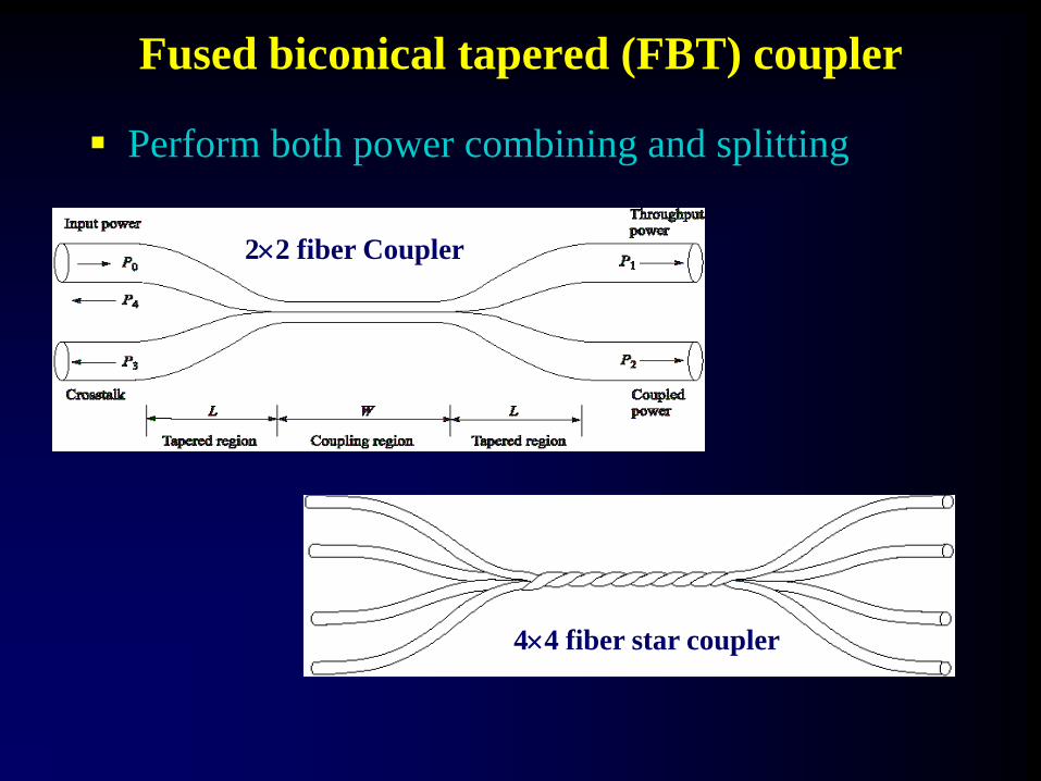
Fused biconical tapered (FBT) coupler
22 fiber Coupler
44 fiber star coupler
Perform both power combining and splitting

Four-channel Wavelength Dependent Multiplexer
Made using Mach-Zehnder Interferometery Technique
Four channel WDM made using three 22 MZI elements

Reflection Grating
• A grating can separate individual wavelengths since the
grating equation is satisfied at different points in the imaging
plane for different wavelengths.
Constructive Interference
(sini - sind) = m
Grating equation

Fiber Bragg Grating (FBG)
Constructed within an optical fiber for accessing individual
wavelengths in the closely spaced spectrum of DWDM systems.
High - performance all fiber device ; low cost, low loss, easy to
couple, simple to packaging etc.
FBG Video

WD_DEMUX Device
Simple demultiplexing function Using FBG and optical circulator
DEMUX to extract desired wavelength, a circulator is
used in conjunction with the FBG.
Infinera ‘s Photonic ICWDM

Tunable DFB/DBR Laser Sources
Tunable laser characteristics
Tunable DBR Laser
Tunning achieved either by :
• Changing the temperature
(0.1nm/ oC)
• Altering injection current

Tunable Optical Filter
Basic concept of tunable optical filter
Operates over a frequency range , and is electrically
tuned to allow only one optical frequency band to pass
through.

Optical Add/Drop MUX (OADM)
Multiple tunable fiber grating used in conjunction with two
optical circulators to add and drop any number of N different
wavelength.
To add or drop wavelengths to DWDM system

Each wavelength still behaves as if it has it own "virtual fibre"
Wavelengths can be added and dropped as required at
some intermediate location
Transmitters
DWDM
Multiplexer
Power
Amp Line
Amp
Receive
Preamp
200 km
DWDM
DeMultiplexe
r
Receivers Add/Drop
Mux/Demux
Optical
fibre
DWDM System with Add-Drop

WDM/DWDM Ring

DWDM Long Haul
Uses DWDM standard optics
Introduces three regions; S, C & L
S band from 1440 nm to 1500 nm
C band from 1530 nm to 1565 nm
L band from 1570 nm to 1620 nm
Amplifiers only available in the C&L bands
Dispersion compensation with amplifier

Non Linear Effects in DWDM System
Nonlinear effects are function of the total power coupled to
the fiber and the interaction length, they limit the maximum
number of wavelength channels that can be transmitted over
a particular distance.
Five optical NLEs that can cause degradation of the
transmitted signals as listed .
Stimulated Brillouin Scattering (SBS)
Stimulated Raman Scattering (SRS)
Self Phase Modulation (SPM)
Cross Phase Modulation (XPM)
Four Wave Mixing (FWM)

Among the five fiber nonlinearity effects
SBS and SRS arise from interaction between light and
acoustic or optical phonon (due to lattice or molecular
vibrations),
whereas SPM, XPM and FWM are caused by the Kerr
effect, where intensity modulation of a signal is converted
through refractive index nonlinearity to modulation of
phase leading to excessive pulse broadening.

Engineering Problems
DWDM is an analog problem
• Optical noise floor/SNR on amps
• Guard bands on adjacent signals
• Linear impairments
» Attenuation
» Chromatic Dispersion
• Non linear, cumulative impairments
» Polarization Mode Dispersion (PMD)
» Four Wave Mixing
» Non Linear Effects
Requires high degree of Signal maintenance

DWDM System Deployment
Important challenges in designing DWDM networks
To meet these challenges, various signal-impairment effects that
are inherent in OFC links must be taken care in design practices
• Transmission of different wavelength channels at the highest
possible bit rate.
• Transmission over the longest possible distance with the
smallest number of optical amplifiers.
• Network architecture that allow simple and efficient network
operation, control, and management.

Polarization-mode dispersion(PMD): very serious
impediment for links operating at 10 Gb/s and higher.
Cannot be easily mitigated
Group velocity dispersion (GVD): limit the bit rate by
temporally spreading a transmitted optical pulse.
Can be minimized by operation in low-dispersion window;
• 1310nm for SMF
• 1550nm for DSF
Nonuniform gain across the desired wavelength range
of EDFAs in WDM link.
Must be equalized over the desired wavelength range.

Reflections from splices and connectors that can cause
instabilities in laser sources.
Can be eliminated by the use of optical isolators.
Nonlinear inelastic scattering processes, SBS and SRS
Keeping launched power below these thresholds.
Nonlinear variations of the refractive index in a silica
fiber that occur because the R.I. is dependent on
intensity changes in the signal.
Either working at low input powers or large core fibers.

Signal maintenance using Optical Devices

High Capacity OFC System
Experimental setup for 55 wavelengths WDM transmission using SMFs
and DCFs in the link
Achieved data rate of 1.1 Tb/s – corresponds to sending almost the entire
contents of 1000 copies of a 30-volume encyclopedia in 1 second

Transmitters
DE
MU
X
Receivers
EDFA EDFA EDFA
Metropolitan-Access Network
Network Management Layer
Add/Drop
i i
Digital Client Layer Optical Channel (OC-N) Layer
Optical Layers Optical Multiplexing Section Layer (OMS-L)
Optical Transmission Section Layer (OTS-L)
Digital Client Layer SONET/SDH/PDH/ATM/ IP/etc. Digital Hierarchy Layer
MU
X
n n
1
2
1
2
Ro
ute
r EDFA = Erbium-doped fiber amplifier
MUX = Multiplexer
DEMUX = Demultiplexer
The Optical Network System

FORESIGHT…
Lightwave Communication Systems Employing, DWDM,
EDFAs and Soliton Pulses
“ZERO LOSS & NEAR INFINITE BANDWIDTH”
Provide with a network capable of
handling almost all our information
needs and resulting in a true information
based society !

Questions?