PRODUCT SELECTION SURGE PROTECTION … include the switching of power circuits, the operation of...
52
SURGE PROTECTION SOLUTIONS ERICO · www.erico.com PRODUCT SELECTION
Transcript of PRODUCT SELECTION SURGE PROTECTION … include the switching of power circuits, the operation of...

SURGE PROTECTION SOLUTIONS
ERICO · www.erico.com
PRODUCT SELECTION

WWW.ERICO.COM2
NOTE: Product application information given in this document is of a general nature. Installers of the product are cautioned to ensure product is always installed in accordance with any applicable National Standards, Codes, and Practices.

COORDINATED FACILITY PROTECTION 3
or from switching induced surges. Costs can range from degradation of electrical or electronic systems to data loss, equipment destruction or injury to personnel. Some of these costs can appear relatively minor but the loss of an essential service or revenues associated with a facility or plant shut down can be enormous.
Sources of Transients and SurgesAlthough lightning is the most spectacular form of externally generated surges, it is only one source of over-voltage. Other sources include the switching of power circuits, the operation of electrical equipment by neighboring industries, the operation of power factor correction devices, and the switching and clearing of faults on transmission lines. It is important to note that lightning does not need to directly strike a power line for such
damage to occur; a strike several hundred meters away can induce large damaging transients, even to underground cables.
It is estimated that 70 to 85% of all transients are generated internally within one’s own facility by the switching of electrical loads such as lights, heating systems, motors and the operation of office equipment.
Modern industry is highly reliant on electronic equipment and automation to increase productivity and safety. The economic benefits of such devices are well accepted. Computers are commonplace and microprocessor-based controllers are used in most manufacturing facilities. Microprocessors can also be found embedded in many industrial machines, security & fire alarms, time clocks and inventory tracking tools. Given the wide range of transient sources and the potential cost of disruption, the initial installed cost of surge protection can readily be justified for any facility.As a guide, the cost of protection should
be approximately 10% of the cost of the facility’s economic risk.
Critical FactorsCritical factors need to be considered when determining the need for facility protection. Many factors can be determined by answering the following questions:
• What is the risk to personnel? • What is the risk of equipment damage? • What are the consequences of equipment failure? • Is the equipment associated with an essential service? • How will equipment failure affect overall facility
operation and revenue generation?• What are the legal implications of providing
inadequate protection?
The statistical nature of lightning and the broad spectrum of energy delivered by a lightning flash, the problems created by various power generation and distribution systems, and the continued trend to more sensitive and specialized electronics, requires careful selection of available technologies if adequate protection is to be provided.
What are the costs of inadequate protection?The costs that can result from inadequate protection are many and varied. The type of equipment within a facility will have a direct impact on the damage that can occur. Robust equipment, such as lighting and air-conditioning systems, are often able to withstand impulses as high as 1500 volts and are not as sensitive to the rapid rate-of-rise exhibited by the pre-clamped surge waveform as are electronics. These systems are often not critical to the continuing operation of the site and therefore usually do not require the premium level of protection that is essential for more sensitive equipment.
However, significant damage can occur, even to the more robust systems, as a result of lightning induced surges resulting within a radius of several kilometers,
Damage to vital equipment caused by destructive surges and transients.
THE NEED FOR COORDINATED PROTECTION
WWW.ERICO.COM4
Load Cell Protector
WEIGH BRIDGE
Ground
Load Cell Protector
TelephoneLine
Potential EqualizationClamp
CENTRAL PROCESS MONITORING FACILITY
UniversalTransientBarriers
UTB
DINLINESurge Filter
Line Surge Protectors (LSPs)Remote
Sensor Control Program
LogicController
Lightning protection principlesrecommend that all external cablingenter the building at a common point.
PROGRAMLOGICCONTROLLER
Overhead High Voltage TransmissionLines
GroundAC TransformerSub Station MANUFACTURING FACILITY
Where building facilities are separated by less than 30 metres, building grounding systems should be bonded together.
DINLINESurge Filter
UniversalTransientBarriers
SurgeReductionFilter
DistributionBoard
Ground
Ground
Ground
GroundGround
Ground
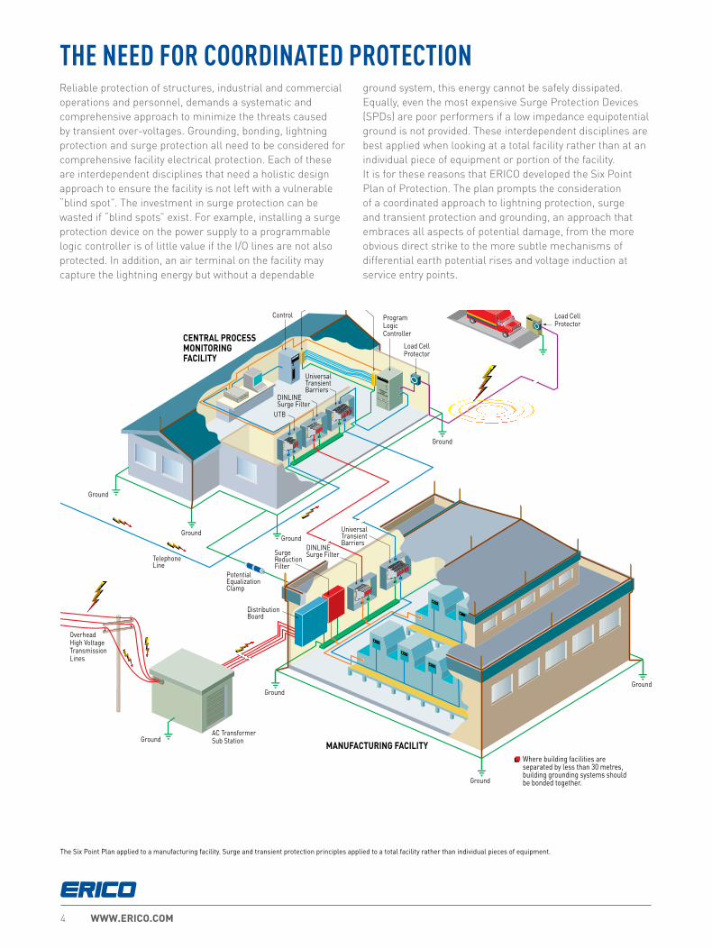
Reliable protection of structures, industrial and commercial operations and personnel, demands a systematic and comprehensive approach to minimize the threats caused by transient over-voltages. Grounding, bonding, lightning protection and surge protection all need to be considered for comprehensive facility electrical protection. Each of these are interdependent disciplines that need a holistic design approach to ensure the facility is not left with a vulnerable “blind spot”. The investment in surge protection can be wasted if “blind spots” exist. For example, installing a surge protection device on the power supply to a programmable logic controller is of little value if the I/O lines are not also protected. In addition, an air terminal on the facility may capture the lightning energy but without a dependable
ground system, this energy cannot be safely dissipated. Equally, even the most expensive Surge Protection Devices (SPDs) are poor performers if a low impedance equipotential ground is not provided. These interdependent disciplines are best applied when looking at a total facility rather than at an individual piece of equipment or portion of the facility. It is for these reasons that ERICO developed the Six Point Plan of Protection. The plan prompts the consideration of a coordinated approach to lightning protection, surge and transient protection and grounding, an approach that embraces all aspects of potential damage, from the more obvious direct strike to the more subtle mechanisms of differential earth potential rises and voltage induction at service entry points.
The Six Point Plan applied to a manufacturing facility. Surge and transient protection principles applied to a total facility rather than individual pieces of equipment.
THE NEED FOR COORDINATED PROTECTION

COORDINATED FACILITY PROTECTION 5
1
2
5
43
Power Protection TVSS Device
Communications Line Protection Device
Ground Electrode
Power Distribution Panel
Telephone Main Distribution Frame
PCS, Radio & Telemetry Equipment
Power Ground
AC Transformer Sub Station
Overhead Distribution Voltage Transmission Lines
Telephone Lines
Direct Lightning Strike
ERICO SYSTEM 3000 Active Lightning Protection System
Capture the lightning strike
Dissipate Energy into the Grounding System
Low Impedance Ground using flat copper radials and
Ground Enhancement Material
Inspection Well
Safely Convey Energy to Ground
Protect Incoming AC Power Feeders
IS File
Server
PABX
InverterRectifier
Batteries
Ground Potential Equalization Bonding
TVSS
Remote Data Terminal
Sub-Distribution BoardBond All Ground
Points Together
PrinterBilling Computer
Signal Control Lines
Induced Surge
ERICO SYSTEM 3000 Active Lightning Protection System
ERICO SYSTEM 2000 Conventional Lightning Protection System
The Six Point Plan of Protection from ERICOCapture the lightning strike.Capture the lightning strike to a known and preferred attachment point using a purpose-designed air terminal system.
Convey this energy to ground.Conduct the energy to the ground via a purpose-designed downconductor.
Dissipate energy into the grounding system.Dissipate energy into a low impedance grounding system.
Bond all ground points together.Bond all ground points to eliminate ground loops and create an equipotential plane.
Protect incoming AC power feeders.Protect equipment from surges and transients on incoming power lines to prevent equipment damage and costly operational downtime.
Protect low voltage data/telecommunications circuits.Protect equipment from surges and transients on incoming telecommunications and signal lines to prevent equipment damage and costly operational downtime.
1
234
5
6
6 Protect Low Voltage Data/Telecommunications Circuits
SIX POINT PLAN OF PROTECTIONBy following the Six Point Plan of Protection, ERICO customers are able to implement the most effective solutions to individual lightning, grounding and surge problems while retaining an integrated protection philosophy.
Point 5 of the Six Point Plan advocates protection of AC power services, advocating a coordinated approach to surge protection, where the first stage of defense is the installation of primary protection devices at the mains supply service entrance, followed by secondary protection at distribution branch panels and where necessary, at point-of-use applications.
Point 6 recognizes the need to provide effective surge protection on cables supplying telecommunications, signal and data management equipment.

WWW.ERICO.COM6
ERICO EXPERTISE
The ERICO advantage is our approach to the complete Facility Electrical Protection Solution. Well designed and high quality Surge Protection is critical to a facility equipment’s reliable operation, however it is only part of the solution.
ERICO therefore offers the complete range and expertise in grounding, bonding, surge and lightning protection, providing the complete solution worldwide and across applications including Commercial, Industrial, Telecom, Utility and Railway. Our service and expertise encompasses more than just the product.
PRODUCT TESTING To effectively meet market requirements and ensure our products are designed and tested to the highest of performance standards, ERICO has invested in state of the art testing equipment that is able to:
• Support application testing for clients – to ensure your equipment is adequately protected.
• Participate in the UL Client Test Data Program.
• Support competitive product testing.
• Test and evaluate to a range of mechanical, electrical and environmental requirements.
HISTORY ERICO continues to be a pioneer in the low voltage Surge Protection industry, having been involved in grounding and bonding applications for over 100 years, and as a manufacturer of SPDs for over thirty years.
Our involvement in the industry predates the creation of the initial IEC and UL low voltage surge protection standards. We’ve been on the journey since the early days of Low Voltage AC surge protection, with the issuing of the IEEE587 standard in 1980, and we have been active on all major worldwide SPD standards committees and industry bodies (including IEEE, IEC, and UL) since.
SEMINARS AND SITE AUDITS Each year ERICO conducts hundreds of seminars in numerous countries around the world, educating specifiers, engineers, and installers on Facility Electrical Protection, of which surge protection plays a key role.

COORDINATED FACILITY PROTECTION 7
CERTIFIED SURGE PROTECTION DEVICES
ERICO surge protective devices (SPDs) provide the option for traditional construction or TD technology. For example, the DT product line features traditional construction, while the EDT product line features with TD technology. These product lines have been designed and independently tested and certified to the latest editions of both IEC61643-11 and UL1449 Ed4.
This provides the user of the product peace of mind that the products will perform safely in application, and also perform to the claimed ratings provided. Both these standards have stringent tests that are not easy to pass, but essential to ensure the product is designed well for safe behavior, and for effective protection performance to the product ratings.
Compliance to these standards are required by code in many countries, however still many countries around the world do not require compliance, leaving those countries vulnerable
to poorly performing products. An informed buyer will avoid non-compliant product, instead demanding compliance to one or both of these standards, factually verified by an independent third party test laboratory certificate. Compliance to these
standards alone however should be considered a benchmark or minimum requirement, as there are certain enhanced performance requirements that may be advantageous for some applications.
One example of this is how the SPD performs during an AC overvoltage
event. In both standards referenced above, the requirement is for the SPD to safely disconnect from service during these events, however a better solution is for the SPD to survive such an event, thereby continuing to provide protection to your valuable equipment being protected.
ERICO’s TD technology delivers just that, a true step-up in performance for SPDs. Our SPDs with TD technology have been designed to be unaffected by the AC overvoltages applied during testing, while not compromising the clamping performance. This provides them with the ability to survive extreme overvoltage conditions and still be operational afterwards to protect your valuable equipment from subsequent surges and transients.
This extends greatly the life expectancy of the SPD within the most extreme environments, saving maintenance work and reducing operational downtime.

WWW.ERICO.COM8
TRANSIENT DISCRIMINATING TECHNOLOGY
To meet the fundamental requirements of performance, longer service life and greater safety under real world conditions, ERICO has developed Transient Discriminating (TD) Technology.
This quantum leap in technology adds a level of “intelligence” to the Surge Protection Device enabling it to discriminate between sustained abnormal overvoltage conditions (Temporary Over Voltages – TOVs) and true transient or surge events. Not only does this help ensure safe operation under practical application, but it also prolongs the life of the protector since permanent disconnects are not required as a means of achieving internal over-voltage protection.
TRADITIONAL TECHNOLOGIESConventional SPD technologies utilizing metal oxide varistors and/or silicon avalanche diodes to clamp or limit transient events are susceptible to sustained 50/60 Hz mains over-voltage conditions (TOVs) which often occur during faults to the utility system. Such occurrences present a significant safety hazard when the suppression device attempts to clamp the peak of each half cycle on the mains overvoltage.
This condition can cause the device to rapidly accumulate heat and in turn fail with the possibility of inducing a fire hazard. The diagram shows how a traditional SPD is chosen to have a nominal clamping voltage that is above the peak of the nominal AC mains voltage. However, in the lower diagram, it can be seen that when the AC mains experiences a Temporary Over-Voltage (TOV), the SPD attempts to clamp the over-voltage, and rapidly heats up, resulting in failure, potentially accompanied by fire or explosion.
Nominal ClampingVoltage on 50/60 Hz
Nominal AC MainsOperating Voltage
Nominal ClampingVoltage on 50/60 Hz
Nominal AC MainsOperating Voltage
TOV Condition
SPD in Conduction
Repetitive Clamping Causes SPDto Heat Up, Possibly Exploding orCausing a Fire

COORDINATED FACILITY PROTECTION 9
THE CORE OF TD TECHNOLOGY
Effectively, TD Technology allows the SPD to have two clamping levels – one well above the peak of a TOV (up to twice its nominal AC voltage!), and the other much lower, to effectively and swiftly clamp lightning transients.
As the explanatory illustration shows, this allows the TD circuit to still remain operational after TOV events, thus continuing to clamp transients and providing a much longer operational life. For example, the IEC 61643-11 standard applies a test of 442 Vac for two hours from Line to Neutral for SPDs intended to operate at 230 Vac. While most SPDs fail safely during this test, ERICO’s EDT2 Series SPDs are unaffected by this stringent test, and remain completely operational. The IEC 61643-11 standard calls this Withstand mode, as opposed to Safe Failure mode.
ERICO SPDs that incorporate TD Technology are especially recommended for any site where sustained over-voltages are known to occur, and where failure of traditional SPD technologies cannot be tolerated.
The secret to ERICO’s Transient Discriminating Technology is its active frequency discrimination circuit.This patented device can discriminate between a temporary over-voltage (TOV) condition and a very fast transient, which is associated with lightning or switching-induced surges. When the transient frequencies are detected, the patented Quick-Switch within TD activates to allow the robust protection to limit the incoming transient. The frequency discriminating circuit that controls the Quick-Switch helps ensure that the SPD device is immune to the effects of a sustained 50 or 60 Hz TOV. This allows the device to keep operating, in order to help provide safe and reliable transient protection, even after anabnormal over-voltage condition has occurred.
Traditional SPD, at best, disconnects safely during TOV event.
Until replaced, further surges go unimpededstraight to the equipment to be protected!
Traditional SPD voltage clamping
TD Technology clampstime after time!
TD technology clamping
1. Transient Impulse
2. Substantial Over-voltage
1. Transient Impulse
Typical Supply Problems
Traditional Technology Response
TD Technology Solution
TD Technology ProvidesContinued Protection -
Even After Over-Voltages
Traditional Technology
ThermalDisconnect
ThermalDisconnect
TD Quick Switch
Active TD Technology

WWW.ERICO.COM10
Class of SPD
In the IEC system, SPDs are tested to various Test Classes, intended to assess and assure their suitability for use in different locations and circumstances. Strictly speaking, the Class refers to the type of test, not to the SPD. However, in common usage, SPDs are referred to by their Class, For example, a Class I SPD is an SPD that has been tested to Class I requirements (of a specified severity), and so on. The Test Classes are as follows:
Class I – Tested with simulated partial conducted lightning current impulses. These SPDs would be used at points of high exposure, such as where the line close to the SPD might be directly struck by lightning, or at the point of entry to a building fitted with a direct strike Lightning Protection System (LPS).
Class II – Tested with shorter duration current impulses. These SPDs would be installed where the surge currents are expected to be less. This could be at the main power entry point of a building in a non-exposed location (surrounded by taller buildings, for example), or at sub-panels within the building.
Class III – Tested with voltage impulses. These SPDs would be installed at equipment to be protected, and are only expected to handle residual voltages surges that “got past” upstream Class I or II SPDs, and the associated small surge currents. Often, for convenience, Class II protectors are used at these locations as well.
In the illustration above, the type of SPDs installed at the Main Distribution Board, Distribution Boards, and the Equipment to be protected would be as follows:
There are a number of IEC standards that work together to provide a system of classifying the power system, the over-voltages that can occur at different points in the system, the performance and application of SPDs, and the relative susceptibility of end use equipment to lightning surges. The most directly relevant are the IEC 62305 series standards dealing with both lightning protection and surge protection, and the IEC 61643 series standards covering testing, selection, and application of SPDs.
BUILDING SITUATION MDB DB EQUIPMENT
Highly exposed, or fitted with LPS Class I Class II Class III (or II)
Less exposed, no LPS Class II Class II Class III (or II)
TEST CLASS PARAMETER DESCRIPTION
Class I Impulse Current, IimpThis current impulse has a 10/350 us waveform.
Class II
Nominal Discharge Current, In
This current impulse has a waveform of 8/20us, and is nominal because the SPD has to successfully handle a sequence of 15 of these impulses.
Maximum Discharge Current, Imax
This current impulse has a waveform of 8/20us, and is the maximum 8/20us impulse the SPD can handle. It is an optional parameter.
Class IIIOpen circuit voltage of the combination wave generator, Uoc
All Classes
Voltage Protection Level, Up
Fitting SPDs at all three locations may not be necessary, depending on the building size, and wiring length. Generally, SPDs are always fitted at the point of entry, and in smaller equipment rooms may just be, additionally, at the equipment. In larger buildings, spread over multiple floors or large areas, SPDs would usually be provided at the distribution boards, and additionally at sensitive or critical equipment.
SPDs are primarily rated according to how large a surge current magnitude they can handle, and how well they limit the voltage while conducting that surge current. These parameters are:
It is possible to test one SPD type at more than one Test Class. SPDs are marked and specified with the parameters they have been successfully tested to.
SELECTION AND APPLICATION OF AC POWER SYSTEM SPDs (IEC SYSTEM)
MDB DB
EQUIPMENT
EQUIPMENT

COORDINATED FACILITY PROTECTION 11
SELECTION AND APPLICATION OF AC POWER SYSTEM SPDs (IEC SYSTEM)
R E C O M M E N D E D P R O D U C T S
PROD
UCT
SERI
ES
SRF N SERIESDT1 SERIES
DT2 SERIESEDT2 SERIES
TSF SERIES
DISTRIBUTED CIRCUITS,POWER OUTLETS, CIRCUITS REMOTE
FROM POINT-OF-ENTRY
SUB CIRCUITS ORNEAR TO
POINT-OF-ENTRY
POINT-OF-ENTRY INNER CITY SITES
POINT-OF-ENTRYHIGHLY EXPOSED OR
CRITICALLY IMPORTANT SITES
POINT-OF-ENTRYEXPOSED OR RURAL
SITES
S P D C L A S S E S A N D C AT E G O R I E SCAT ACAT BCAT CANSI/IEEE C62.41
IEC 61643-11 Test Class
VDE ClassificationI I, II II IIIA B C D

WWW.ERICO.COM12
TN-C SystemIn this system, the neutral and protective earth conductor are combined in a single conductor throughout the system. This conductor is referred to as a PEN, a “Protective Earth & Neutral”. All exposed conductive equipment parts are connected to the PEN.
For example, on a 230 V Ph-N system, Ph-PEN protection should have a Uc rating of at least 255 V. Generally an SPD with a Uc rating of at least 275 V would be selected for 220 to 240 V systems. Often, to allow for power supply voltage fluctuations, a Uc of at least 1.3 x Uo is recommended, such as a Uc of 300 V for a 230 V system, or ERICO’s TD technology would be chosen.
TN-S SystemIn this system, a separate neutral and protective earth conductor are run throughout. The Protective Earth (PE) conductor is normally a separate conductor, but can also be the metallic sheath of the power cable. All exposed conductive equipment parts are connected to the PE conductor.
* Install fuse A if supply fuse B exceeds back-up overcurrent protection rating
Source Main Distribution Board Sub/Branch Distribution Board
* Install fuse C if supply fuse D exceeds back-up overcurrent protection rating
* Install fuse A if supply fuse B exceeds back-up overcurrent protection rating
SPDs shown connected L-N and N-PE.May also be connected L-PE and N-PE.
Source Main Distribution Board Sub/Branch Distribution Board
* Install fuse C if supply fuse D exceeds back-up overcurrent protection rating
SPDs INSTALLED DESCRIPTION EXAMPLE PRODUCT
Phase to PEN (“3+0”) At least 1.1 x Uo DT230030R
Having determined the Class of SPD required, the correct voltage and configuration needs to be determined. The standard IEC 60364-1 details the following system configurations. In the descriptions that follow, Uo is used for the nominal systems voltage, and Uc is used for the maximum continuous operating voltage (this is a parameter of an SPD).
SELECTION AND APPLICATION OF AC POWER SYSTEM SPDs (IEC SYSTEM)

COORDINATED FACILITY PROTECTION 13
SPDs INSTALLED DESCRIPTION EXAMPLE PRODUCT
Phase to PE (“4+0”), or At least 1.1 x Uoc DT230040R
Phase-N, and N-PE (“3+1”) DT230031R
SPDs INSTALLED DESCRIPTION EXAMPLE PRODUCT
MDB: Phase to PEN (“3+0”)DB: Phase to PEN (“4+0”), orPhase-N, and N-PE (“3+1”)
At least 1.1 x Uo DT130030R, DT230040R, DT230031R
TN-C-S SystemIn this system, the supply is configured as per TN-C, while the downstream installation is configured as per TN-S. The combined PEN conductor typically occurs between the substation and the entry point into the building, and earth and neutral are separated in the Main Distribution Board. This system is also known as Protective Multiple Earthing (PME) or Multiple Earthed Neutral (MEN). The supply PEN conductor is earthed at a number of points throughout the network and generally as close to the consumer’s point-of-entry as possible.
* Install fuse A if supply fuse B exceeds back-up overcurrent protection rating
SPDs shown connected L-PE and N-PE.May also be connected L-N and N-PE.
Source Main Distribution Board Sub/Branch Distribution Board
* Install fuse C if supply fuse D exceeds back-up overcurrent protection rating
For example, on a 230 V Ph-N system, Ph-PE (or Ph-N) protection should have a Uc rating of at least 255 V. Generally an SPD with a Uc rating of at least 275 V would be selected for 220 to 240 V systems. Often, to allow for power supply voltage fluctuations, a Uc of at least 1.3 x Uo is recommended, such as a Uc of 300 V for a 230 V system, or ERICO’s TD technology would be chosen.
For example, on a 230 V Ph-N system, Ph-PE (or Ph-N) protection should have a Uc rating of at least 255 V. Generally an SPD with a Uc rating of at least 275 V would be selected for 220 to 240 V systems. Often, to allow for power supply voltage fluctuations, a Uc of at least 1.3 x Uo is recommended, such as a Uc of 300 V for a 230 V system, or ERICO’s TD technology would be chosen.
SELECTION AND APPLICATION OF AC POWER SYSTEM SPDs (IEC SYSTEM)

WWW.ERICO.COM14
SPDs INSTALLED DESCRIPTION EXAMPLE PRODUCT
Phase to N, N-PE (“3+1”) At least 1.1 x Uoc DT130031R, DT230031R
For example, on a 230 V Ph-N system, Ph-N protection should have a Uc rating of at least 255 V. Generally an SPD with a Uc rating of at least 275 V would be selected for 220 to 240 V systems. Often, to allow for power supply voltage fluctuations, a Uc of at least 1.3 x Uo is recommended, such as a Uc of 300 V for a 230V system, or ERICO’s TD technology would be chosen.
In the TT system, in order for overcurrent protective devices (fuses and circuit breakers) to operate in the intended manner, it is important that SPDs must not connect directly from phase to protective ground, but from phase to neutral and neutral to ground. Therefore, the Neutral-to-PE SPD carries both the PE to neutral impulse current and the PE to phase impulse currents. This SPD is recommended to be a GDT (Gas Discharge Tube) due to their generally superior energy handling characteristics.
TT SystemA system having one point of the source of energy earthed and the exposed conductive parts of the installation connected to independent earthed electrodes. The incoming supply neutral is not earthed at the main distribution board.
* Install fuse A if supply fuse B exceeds back-up overcurrent protection rating
Source Main Distribution Board Sub/Branch Distribution Board
* Install fuse C if supply fuse D exceeds back-up overcurrent protection rating
SELECTION AND APPLICATION OF AC POWER SYSTEM SPDs (IEC SYSTEM)

COORDINATED FACILITY PROTECTION 15
IT SystemA system having no direct connection between live parts and earth, but all exposed conductive parts of the installation being connected to independent earthed electrodes. The source is either floating or earthed through a high impedance (to limit fault currents). This means that during a Phase to Earth fault, the systems continues to operate. This is detected, and maintenance efforts commenced to rectify the fault. However, during this time, the Phase to Earth voltage rises to the usual Line to Line voltage, and installed SPDs must withstand this during this time. Most installed IT systems do not utilise a neutral conductor - equipment is powered from line to line. The IT system is typically used in older installations in countries such as Norway and France. It is also used in special applications, such as intensive care wards of hospitals and special industrial applications.
SPDs INSTALLED DESCRIPTION EXAMPLE PRODUCT
Phase to PEN (“3+0”) At least 1.73 x Uo DT230030R
SPDs INSTALLED DESCRIPTION EXAMPLE PRODUCT
Phase to PEN (“4+0”) At least 1.73 x Uo DT130040R, DT230040R
For example, on a 230 V Ph-N system, Ph-PE and N-PE protection should have a Uc rating of 440 V (allowing for the L-L voltage and a 10% tolerance). Often an additional safety margin is applied, to allow for instabilities that can occur in the ungrounded IT system, such as a Uc of 480 V.
SELECTION AND APPLICATION OF AC POWER SYSTEM SPDs (IEC SYSTEM)

WWW.ERICO.COM16
CLASS I / CLASS II SURGE PROTECTIONDT1The DIN Rail mounted DT1 family of SPDs provide reliable and efficient protection against voltage transients within the IEC Class I & II and UL Type 1 & 2 environments. Tested and independently certified to the IEC (via VDE) and UL standards, the DT1 Series provides a range of safety and performance features for the harshest environments and suitable for protection within a wide range of applications.
DT2 The DIN Rail mounted DT2 family provides many of the same benefits as the DT1 Series but is specifically designed to fit within the parameters of IEC Class II and UL Type 2 environments. Targeting the Class II / Type 2 classification allows the system designer to effectively select the correct coordinated protection while keeping total project costs in check.
EDT2 The DIN Rail mounted EDT2 family of SPDs provide reliable protection against voltage transients within the IEC Class II and UL Type 2 environments. In addition, ERICO’s Transient Discriminating (TD) technology ensures continued operation during and after sustained and abnormal over-voltage events. Tested and independently certified to the IEC (via VDE) and UL standards, the EDT2 Series provides a range of safety and performance features for the harshest environments and suitable for protection within a wide range of applications. The EDT2 Series provides extended service life in the harshest of environments, ensuring your equipment and systems are kept safe and operational through extreme abnormal voltage conditions.
PRODUCTS

17
DATA / SIGNAL PROTECTIONLightning or induced surges can destroy or
compromise signal communications systems and data. ERICO offers multiple series of data and signal surge protection devices designed to provide transient protection for equipment
from induced surges. These are also well-suited to the protection of industrial equipment and are compact in size, while
offering high surge carrying capacity. ERICO data and signal surge protection offers a complete solution to eliminate damage,
downtime, and power disruption..
GROUNDING, BONDING AND CONNECTIVITY SOLUTIONS
SURGE FILTERS
SRF The SRF (Surge Reduction Filters) product family combines
high-energy surge diversion with surge filtering, making them ideal for primary service protection applications. Their efficient
low pass filtering stage dramatically reduces the rate-of-voltage rise and the let-through voltage thereby substantially reducing
the risk of physical equipment damage. They incorporate TD technology making them robust against AC power system
temporary overvoltages, and their standards compliance to IEC 61643-11 Class I & Class II ensure maximum product
performance with maximum product safety.
TSFThe Transient Surge Filter (TSF) product family
combines ERICO’s Transient Discriminating (TD) technology with a low pass filter to protect against
transient events and attenuate small signal RFI/EMI noise problems. Perfect for PLC
controllers, SCADA systems, motor control centers, and other similar applications, the TSF
also features serviceable surge modules and a compact form factor. The TSF range of products
are certified to UL 1449 4th Edition, UL 1283 5th Edition (EMI Filtering), and IEC 61643-11 Class II.

WWW.ERICO.COM18
SURGE PROTECTION PRODUCT SELECTIONThe various product solutions available are listed below. The basic division is into power protection and signal protection. Power protectors are further divided into shunt protection and series (filtering) protection. Signal protectors are genberally divided by connectors types and application.
POWER PROTECTION - DINRAIL TEST CLASS 1 AND 2 PROTECTORS
SHUNT PROTECTION FOR POWER CIRCUITS
(E)DTX YYY ZZ (R) (E)DTX = PRODUCT FAMILY DT1 = Dinrail Test Class 1 DT2 = Dinrail Test Class 2 EDT2 = Enhanced Dinrail TestClass 2
YYY = VOLTAGE 75 = 75 V 150 = 150 V 300 = 300 V 350 = 350 V 480 = 480 V 550 = 550 V (EDT2 only) 750 = 750 V 880 =880 V (EDT2 only)
ZZ = MODE 10 = 1 +0 20 = 2 + 0 30 = 3 + 0 40 = 4 + 0 11 = 1 + 1 31 = 3 + 1
R = REMOTE CONTACTS
SGTX YY (R) SGTX = PRODUCT FAMILY SGT1 = Spark Gap Test Class 1 SGT2 = Spark Gap Test Class 2
YY = SURGE RATING 40 = 40 kA In [T2] 50 = 50kA Iimp [T1]
R = REMOTE CONTACTS(SGT240R only)
POWER PROTECTION – TRANSIENT SURGE FILTERS
SERIES PROTECTION FOR POWER CIRCUITS (6 A TO 20 A)
TSF XXA YYYV TSF = PRODUCT FAMILY XX = LINE CURRENT6 = 6 A20 = 20 A
YYY = VOLTAGE24 = 24 V (6 A only) 120 =120 V 240 =240 V
POWER PROTECTION – SURGE REDUCTION FILTERS
SERIES PROTECTION FOR POWER CIRCUITS (63 A TO 800 A)
SRF XXXA N SRF = PRODUCT FAMILY XXX = LINE CURRENT 63 = 63 A 125 = 125 A 250 = 250 A 500 = 500 A 800 = 800 A
N = N SERIES
SIGNAL PROTECTION – UNIVERSAL TRANSIENT BARRIERS
GENERAL PURPOSE SIGNAL PROTECTION
UTB XXX SP UTB = PRODUCT FAMILY XXX = VOLTAGE 5 = 5 V 15 = 15 V 30 = 30 V 60 = 60 V 110 = 110 V
S = SINGLE PAIR
TELEPHONE LINE PROTECTION
UTBSA UTB = PRODUCT FAMILY SA = TELEPHONE

COORDINATED FACILITY PROTECTION 19
SURGE PROTECTION PRODUCT SELECTIONSIGNAL PROTECTION – COAXIAL SURGE PROTECTION
GENERAL PURPOSE COAXIAL CABLE PROTECTION
CSP1 XXX YYY CSP1 = PRODUCT FAMILY
XXX = CONNECTOR
NB =N type, F-F bulkhead NMF =N type, male-female BNC = BNC type, male-female SMA = SMA type, male-female
YYY = MODE 90 =90 V 600 = 600 V
SIGNAL PROTECTION – HIGH SPEED PROTECTION
HIGH SPEED TWISTED PAIR KRONE BLOCK PROTECTION
HSP 10 K XXX HSP = PRODUCT FAMILY 10 = 10 PAIR
K = KRONE BLOCK
XXX = VOLTAGE
12 = 12 V 36 = 36 V 72 = 72 V 230 = 230 V
SIGNAL PROTECTION – SUBSCRIBER LINE PROTECTION
GENERAL TWISTED PAIR KRONE BLOCK PROTECTION
SLP 1 RJ11 A SLP = PRODUCT FAMILY 1 = 1 PAIR
RJ11A = RJ11 CONNECTOR
SLP 10 K1F SLP = PRODUCT FAMILY 10 = 10 PAIR K = KRONE BLOCK 1F = FAIL SAFE
SIGNAL PROTECTION – CLOSED CIRCUIT TV
COAXIAL CABLE CCTV
CCTV 12 CCTV = PRODUCT FAMILY 12 = VOLTAGE
SIGNAL PROTECTION – LOCAL AREA NETWORK
GENERAL PURPOSE RJ45 PROTECTION
LAN RJ45 C6P LAN = PRODUCT FAMILY RJ45 = CONNECTOR C6P = CATEGORY 6 PROTECTION

WWW.ERICO.COM20
DT AND EDT SPD FEATURES
SPD STATUS INDICATION
CONVENIENT MODULE AND BASE DESIGN
CLIP LOCKS MODULE IN PLACE FOR VIBRATION RESISTANCE
LOCK BACK CLIP MAKES FOR EASY INSTALLATION
RUGGED CONNECTION TO BASE HANDLES HIGH SURGE CURRENT
KEYING MECHANISM ENSURES CORRECT MODULE
ADVANCED DESIGN AVOIDS FUSING IN MANY INSTALLATIONS
ALARM CONTACTS ALLOW REMOTE STATUS MONITORING
Packed with features and benefits for the user, the DT and EDT line from ERICO represents the latest in product design, development and testing.
20

COORDINATED FACILITY PROTECTION 21
DT1 DIN RAIL SURGE PROTECTION CLASS I+II, 1+0 MODEFEATURES
• Compact, yet high surge rated pluggable design, using minimum DIN rail width
• External back-up fuse is not required up to 315 A
• Retaining clip ensures enhanced vibration and shock resistance performance
• Red/Green status indication and change-over contacts standard for remote monitoring
90 mm
85 mm
18 mm
Certification Details:IEC 61643-11 Class IIEN 61643-11 Type 2UL 1449, 4th Edition Type 1CA
Complies with:
IEC 61643-11:2011EN 61643-11:2012UL 1449, 4th EditionCSA C22.2 No. 269-4
Protection Modes: L-PE, N-PE (only TN-S), L-PEN, L-N
PART NUMBER DT17510R DT130010R DT148010R
IEC ELECTRICAL
Nominal AC Voltage (50/60Hz) Uo / Un 60V 240V 400V
Maximum Continuous Operating Voltage (AC) Uc 75V 300V 480V
Nominal Discharge Current (8/20 μs) In 12.5 kA 12.5 kA 10 kA
Maximum Discharge Current (8/20 μs) Imax 50 kA 50 kA 50 kA
Impulse Discharge Current (10/350 μs) Iimp 12.5 kA 12.5 kA 10 kA
Specific Energy W/R 39 kJ/Ω 39 kJ/Ω 25 kJ/Ω
Voltage Protection Level Up 700V 1400V 2000V
Response Time tA < 25 ns
Back-Up Fuse (max) 315A / 250A gG
Short-Circuit Current Rating (AC) ISCCR 25 kA / 50 kA
TOV Withstand 5s UT 114V 337V 581V
TOV 120 min UT/mode 114V/withstand 442V/safe fail 762V/safe fail
Number of Ports 1
UL ELECTRICAL
Maximum Continuous Operating Voltage (AC) MCOV 75V 300V 480V
Voltage Protection Rating VPR 400V 900V 1500V
Nominal Discharge Current (8/20 μs) In 20 kA 20 kA 20 kA
Short-Circuit Current Rating (AC) SCCR 100 kA 150 kA 200 kA
MECHANICAL
Operating Temperature Range Ta -40° C to +70° C [ -40° F to +158° F}
Terminal Screw Torque Mmax 39.9 Ibf·in [4.5 Nm]
Conductor Cross Section (max) 35mm2 (Solid) / 25mm2 (Stranded)2 AWG (Solid) / 4 AWG (Stranded)
Mounting 35 mm DIN Rail, EN 60715
Housing Material Thermoplastic: Extinguishing Degree UL 94 V-0
Thermal Protection Yes
Operating State / Fault Indication Green Flag / Not Green Flag
Remote Contacts (RC) Yes
RC Switching Capacity AC: 250V/ 1A, 125V/ 1A; DC: 48V/0.5A, 24V/0.5A, 12V/0.5A
RC Conductor Cross Section (max) 1.5mm2 (Solid) / 16 AWG (Solid)
Single Unit Weight pounds 0.371 0.402 0.446
Single Unit Weight grams 168 182 202

WWW.ERICO.COM22
90 mm
85 mm
36 mm
DT1 DIN RAIL SURGE PROTECTION CLASS I+II, 2+0 MODEFEATURES
• Compact, yet high surge rated pluggable design, using minimum DIN rail width
• External back-up fuse is not required up to 315 A
• Retaining clip ensures enhanced vibration and shock resistance performance
• Red/Green status indication and change-over contacts standard for remote monitoring
Certification Details:IEC 61643-11 Class I+IIEN 61643-11 Type 1+2UL 1449, 4th Edition Type 1CA
Complies with:
IEC 61643-11:2011EN 61643-11:2012UL 1449, 4th EditionCSA C22.2 No. 269-4
Protection Modes: L-PE, N-PE
PART NUMBER DT130020R
IEC ELECTRICAL
Nominal AC Voltage (50/60Hz) Uo / Un 240V
Maximum Continuous Operating Voltage (AC) Uc 300V
Nominal Discharge Current (8/20 μs) In 12.5 kA
Maximum Discharge Current (8/20 μs) Imax 50 kA
Impulse Discharge Current (10/350 μs) Iimp 12.5 kA
Specific Energy W/R 39 kJ/Ω
Voltage Protection Level Up 1400V
Response Time tA < 25 ns
Back-Up Fuse (max) 315A / 250A gG
Short-Circuit Current Rating (AC) ISCCR 25 kA / 50 kA
TOV Withstand 5s UT 337V
TOV 120 min UT/mode 442V/safe fail
Number of Ports 1
UL ELECTRICAL
Maximum Continuous Operating Voltage (AC) MCOV 300V
Voltage Protection Rating VPR 900V
Nominal Discharge Current (8/20 μs) In 20 kA
Short-Circuit Current Rating (AC) SCCR 150 kA
MECHANICAL
Operating Temperature Range Ta -40° F to +158° F [-40° C to +70° C]
Terminal Screw Torque Mmax 39.9 Ibf·in [4.5 Nm]
Conductor Cross Section (max) 35mm2 (Solid) / 25mm2 (Stranded)2 AWG (Solid) / 4 AWG (Stranded)
Mounting 35 mm DIN Rail, EN 60715
Housing Material Thermoplastic: Extinguishing Degree UL 94 V-0
Thermal Protection Yes
Operating State / Fault Indication Green Flag / Not Green Flag
Remote Contacts (RC) Yes
RC Switching Capacity AC: 250V/ 1A, 125V/ 1A; DC: 48V/0.5A, 24V/0.5A, 12V/0.5A
RC Conductor Cross Section (max) 1.5mm2 (Solid) / 16 AWG (Solid)
Single Unit Weight pounds 0.779
Single Unit Weight grams 353

COORDINATED FACILITY PROTECTION 23
FEATURES
• Compact, yet high surge rated pluggable design, using minimum DIN rail width
• External back-up fuse is not required up to 315 A
• Retaining clip ensures enhanced vibration and shock resistance performance
• Red/Green status indication and change-over contacts standard for remote monitoring
Certification Details:IEC 61643-11 Class I+IIEN 61643-11 Type 1+2UL 1449, 4th Edition Type 1CA
Complies with:
IEC 61643-11:2011EN 61643-11:2012UL 1449, 4th EditionCSA C22.2 No. 269-4
Protection Modes: L-PEN
DT1 DIN RAIL SURGE PROTECTION CLASS I+II, 3+0 MODE
54 mm
90 mm
85 mm
PART NUMBER DT130030R DT148030R
IEC ELECTRICAL
Nominal AC Voltage (50/60Hz) Uo / Un 240V 400V
Maximum Continuous Operating Voltage (AC) Uc 300V 480V
Nominal Discharge Current (8/20 μs) In 12.5 kA 10 kA
Maximum Discharge Current (8/20 μs) Imax 50 kA 50 kA
Impulse Discharge Current (10/350 μs) Iimp 12.5 kA 10 kA
Specific Energy W/R 39 kJ/Ω 25 kJ/Ω
Voltage Protection Level Up 1400V 2000V
Response Time tA < 25 ns
Back-Up Fuse (max) 315A / 250A gG
Short-Circuit Current Rating (AC) ISCCR 25 kA / 50 kA
TOV Withstand 5s UT 337V 581V
TOV 120 min UT/mode 442V/safe fail 762V/safe fail
Number of Ports 1
UL ELECTRICAL
Maximum Continuous Operating Voltage (AC) MCOV 300V 480V
Voltage Protection Rating VPR 900V 1500V
Nominal Discharge Current (8/20 μs) In 20 kA 20 kA
Short-Circuit Current Rating (AC) SCCR 150 kA 200 kA
MECHANICAL
Operating Temperature Range Ta -40° F to +158° F [-40° C to +70° C]
Terminal Screw Torque Mmax 39.9 Ibf·in [4.5 Nm]
Conductor Cross Section (max) 35mm2 (Solid) / 25mm2 (Stranded)2 AWG (Solid) / 4 AWG (Stranded)
Mounting 35 mm DIN Rail, EN 60715
Housing Material Thermoplastic: Extinguishing Degree UL 94 V-0
Thermal Protection Yes
Operating State / Fault Indication Green Flag / Not Green Flag
Remote Contacts (RC) Yes
RC Switching Capacity AC: 250V/ 1A, 125V/ 1A; DC: 48V/0.5A, 24V/0.5A, 12V/0.5A
RC Conductor Cross Section (max) 1.5mm2 (Solid) / 16 AWG (Solid)
Single Unit Weight pounds 1.133 1.266
Single Unit Weight grams 514 574

WWW.ERICO.COM24
72 mm
90 mm
85 mm
DT1 DIN RAIL SURGE PROTECTION CLASS I+II, 4+0 MODEFEATURES
• Compact, yet high surge rated pluggable design, using minimum DIN rail width
• External back-up fuse is not required up to 315 A
• Retaining clip ensures enhanced vibration and shock resistance performance
• Red/Green status indication and change-over contacts standard for remote monitoring
Certification Details:IEC 61643-11 Class I+IIEN 61643-11 Type 1+2UL 1449, 4th Edition Type 1CA
Complies with:
IEC 61643-11:2011EN 61643-11:2012UL 1449, 4th EditionCSA C22.2 No. 269-4
Protection Modes: L-PE, N-PE
PART NUMBER DT130040R DT148040R
IEC ELECTRICAL
Nominal AC Voltage (50/60Hz) Uo / Un 240V 400V
Maximum Continuous Operating Voltage (AC) Uc 300V 480V
Nominal Discharge Current (8/20 μs) In 12.5 kA 10 kA
Maximum Discharge Current (8/20 μs) Imax 50 kA 50 kA
Impulse Discharge Current (10/350 μs) Iimp 12.5 kA 10 kA
Specific Energy W/R 39 kJ/Ω 25 kJ/Ω
Voltage Protection Level Up 1400V 2000V
Response Time tA < 25 ns
Back-Up Fuse (max) 315A / 250A gG
Short-Circuit Current Rating (AC) ISCCR 25 kA / 50 kA
TOV Withstand 5s UT 337V 581V
TOV 120 min UT/mode 442V/safe fail 762V/safe fail
Number of Ports 1
UL ELECTRICAL
Maximum Continuous Operating Voltage (AC) MCOV 300V 480V
Voltage Protection Rating VPR 900V 1500V
Nominal Discharge Current (8/20 μs) In 20 kA 20 kA
Short-Circuit Current Rating (AC) SCCR 150 kA 200 kA
MECHANICAL
Operating Temperature Range Ta -40° F to +158° F [-40° C to +70° C]
Terminal Screw Torque Mmax 39.9 Ibf·in [4.5 Nm]
Conductor Cross Section (max) 35mm2 (Solid) / 25mm2 (Stranded)2 AWG (Solid) / 4 AWG (Stranded)
Mounting 35 mm DIN Rail, EN 60715
Housing Material Thermoplastic: Extinguishing Degree UL 94 V-0
Thermal Protection Yes
Operating State / Fault Indication Green Flag / Not Green Flag
Remote Contacts (RC) Yes
RC Switching Capacity AC: 250V/ 1A, 125V/ 1A; DC: 48V/0.5A, 24V/0.5A, 12V/0.5A
RC Conductor Cross Section (max) 1.5mm2 (Solid) / 16 AWG (Solid)
Single Unit Weight pounds 1.519 1.696
Single Unit Weight grams 689 769
COORDINATED FACILITY PROTECTION 25
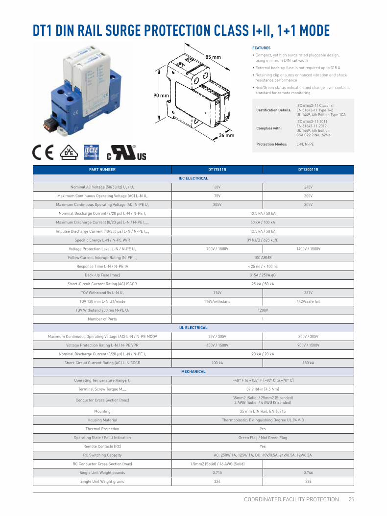
DT1 DIN RAIL SURGE PROTECTION CLASS I+II, 1+1 MODEFEATURES
• Compact, yet high surge rated pluggable design, using minimum DIN rail width
• External back-up fuse is not required up to 315 A
• Retaining clip ensures enhanced vibration and shock resistance performance
• Red/Green status indication and change-over contacts standard for remote monitoring
Certification Details:IEC 61643-11 Class I+IIEN 61643-11 Type 1+2UL 1449, 4th Edition Type 1CA
Complies with:
IEC 61643-11:2011EN 61643-11:2012UL 1449, 4th EditionCSA C22.2 No. 269-4
Protection Modes: L-N, N-PE
PART NUMBER DT17511R DT130011R
IEC ELECTRICAL
Nominal AC Voltage (50/60Hz) Uo / Un 60V 240V
Maximum Continuous Operating Voltage (AC) L-N Uc 75V 300V
Maximum Continuous Operating Voltage (AC) N-PE Uc 305V 305V
Nominal Discharge Current (8/20 μs) L-N / N-PE In 12.5 kA / 50 kA
Maximum Discharge Current (8/20 μs) L-N / N-PE Imax 50 kA / 100 kA
Impulse Discharge Current (10/350 μs) L-N / N-PE Iimp 12.5 kA / 50 kA
Specific Energy L-N / N-PE W/R 39 kJ/Ω / 625 kJ/Ω
Voltage Protection Level L-N / N-PE Up 700V / 1500V 1400V / 1500V
Follow Current Interupt Rating (N-PE) Ifi 100 ARMS
Response Time L-N / N-PE tA < 25 ns / < 100 ns
Back-Up Fuse (max) 315A / 250A gG
Short-Circuit Current Rating (AC) ISCCR 25 kA / 50 kA
TOV Withstand 5s L-N UT 114V 337V
TOV 120 min L-N UT/mode 114V/withstand 442V/safe fail
TOV Withstand 200 ms N-PE UT 1200V
Number of Ports 1
UL ELECTRICAL
Maximum Continuous Operating Voltage (AC) L-N / N-PE MCOV 75V / 305V 300V / 305V
Voltage Protection Rating L-N / N-PE VPR 400V / 1500V 900V / 1500V
Nominal Discharge Current (8/20 μs) L-N / N-PE In 20 kA / 20 kA
Short-Circuit Current Rating (AC) L-N SCCR 100 kA 150 kA
MECHANICAL
Operating Temperature Range Ta -40° F to +158° F [-40° C to +70° C]
Terminal Screw Torque Mmax 39.9 Ibf·in [4.5 Nm]
Conductor Cross Section (max) 35mm2 (Solid) / 25mm2 (Stranded)2 AWG (Solid) / 4 AWG (Stranded)
Mounting 35 mm DIN Rail, EN 60715
Housing Material Thermoplastic: Extinguishing Degree UL 94 V-0
Thermal Protection Yes
Operating State / Fault Indication Green Flag / Not Green Flag
Remote Contacts (RC) Yes
RC Switching Capacity AC: 250V/ 1A, 125V/ 1A; DC: 48V/0.5A, 24V/0.5A, 12V/0.5A
RC Conductor Cross Section (max) 1.5mm2 (Solid) / 16 AWG (Solid)
Single Unit Weight pounds 0.715 0.746
Single Unit Weight grams 324 338
90 mm
85 mm
36 mm

WWW.ERICO.COM26
72 mm
90 mm
85 mm
FEATURES
• Compact, yet high surge rated pluggable design, using minimum DIN rail width
• External back-up fuse is not required up to 315 A
• Retaining clip ensures enhanced vibration and shock resistance performance
• Red/Green status indication and change-over contacts standard for remote monitoring
Certification Details:IEC 61643-11 Class I+IIEN 61643-11 Type 1+2UL 1449, 4th Edition Type 1CA
Complies with:
IEC 61643-11:2011EN 61643-11:2012UL 1449, 4th EditionCSA C22.2 No. 269-4
Protection Modes: L-N, N-PE
DT1 DIN RAIL SURGE PROTECTION CLASS I+II, 3+1 MODE
PART NUMBER DT130031R
IEC ELECTRICAL
Nominal AC Voltage (50/60Hz) Uo / Un 240V
Maximum Continuous Operating Voltage (AC) L-N Uc 300V
Maximum Continuous Operating Voltage (AC) N-PE Uc 305V
Nominal Discharge Current (8/20 μs) L-N / N-PE In 12.5 kA / 50 kA
Maximum Discharge Current (8/20 μs) L-N / N-PE Imax 50 kA / 100 kA
Impulse Discharge Current (10/350 μs) L-N / N-PE Iimp 12.5 kA / 50 kA
Specific Energy L-N / N-PE W/R 39 kJ/Ω / 625 kJ/Ω
Voltage Protection Level L-N / N-PE Up 1400V / 1500V
Follow Current Interupt Rating (N-PE) Ifi 100 ARMS
Response Time L-N / N-PE tA < 25 ns / < 100 ns
Back-Up Fuse (max) 315A / 250A gG
Short-Circuit Current Rating (AC) ISCCR 25 kA / 50 kA
TOV Withstand 5s L-N UT 337V
TOV 120 min L-N UT/mode 442V/safe fail
TOV Withstand 200 ms N-PE UT 1200V
Number of Ports 1
UL ELECTRICAL
Maximum Continuous Operating Voltage (AC) L-N / N-PE MCOV 300V / 305V
Voltage Protection Rating L-N / N-PE VPR 900V / 1500V
Nominal Discharge Current (8/20 μs) L-N / N-PE In 20 kA / 20 kA
Short-Circuit Current Rating (AC) L-N SCCR 150 kA
MECHANICAL
Operating Temperature Range Ta -40° F to +158° F [-40° C to +70° C]
Terminal Screw Torque Mmax 39.9 Ibf·in [4.5 Nm]
Conductor Cross Section (max) 35mm2 (Solid) / 25mm2 (Stranded)2 AWG (Solid) / 4 AWG (Stranded)
Mounting 35 mm DIN Rail, EN 60715
Housing Material Thermoplastic: Extinguishing Degree UL 94 V-0
Thermal Protection Yes
Operating State / Fault Indication Green Flag / Not Green Flag
Remote Contacts (RC) Yes
RC Switching Capacity AC: 250V/ 1A, 125V/ 1A; DC: 48V/0.5A, 24V/0.5A, 12V/0.5A
RC Conductor Cross Section (max) 1.5mm2 (Solid) / 16 AWG (Solid)
Single Unit Weight pounds 1.491
Single Unit Weight grams 676

COORDINATED FACILITY PROTECTION 27
DT2 DIN RAIL SURGE PROTECTION CLASS II, 1+0 MODEFEATURES
• Compact, yet high surge rated pluggable design, using minimum DIN rail width
• External back-up fuse is not required up to 315 A
• Retaining clip ensures enhanced vibration and shock resistance performance
• Red/Green status indication and change-over contacts standard for remote monitoring90 mm
69 mm
18 mm
Certification Details:IEC 61643-11 Class I+IIEN 61643-11 Type 1+2UL 1449, 4th Edition Type 1CA
Complies with:
IEC 61643-11:2011EN 61643-11:2012UL 1449, 4th EditionCSA C22.2 No. 269-4
Protection Modes: L-N, N-PE
PART NUMBER DT27510R DT215010R DT230010R DT248010R
IEC ELECTRICAL
Nominal AC Voltage (50/60Hz) Uo / Un 60V 120V 240V 400V
Maximum Continuous Operating Voltage (AC) Uc 75V 150V 300V 480V
Nominal Discharge Current (8/20 μs) In 20 kA
Maximum Discharge Current (8/20 μs) Imax 50 kA
Voltage Protection Level Up 800V 1250V 1500V 2300V
Response Time tA < 25 ns
Back-Up Fuse (max) 315A / 250A gG
Short-Circuit Current Rating (AC) ISCCR 25 kA / 50 kA
TOV Withstand 5s UT 114V 229V 337V 581V
TOV 120 min UT/mode 114V/withstand 229V/safe fail 442V/safe fail 762V/safe fail
Number of Ports 1
UL ELECTRICAL
Maximum Continuous Operating Voltage (AC) MCOV 75V 150V 300V 480V
Voltage Protection Rating VPR 500V 700V 1200V 1500V
Nominal Discharge Current (8/20 μs) In 20 kA
Short-Circuit Current Rating (AC) SCCR 100 kA 200 kA 150 kA 200 kA
MECHANICAL
Operating Temperature Range Ta -40° F to +158° F [-40° C to +70° C]
Terminal Screw Torque Mmax 39.9 Ibf·in [4.5 Nm]
Conductor Cross Section (max) 35mm2 (Solid) / 25mm2 (Stranded)2 AWG (Solid) / 4 AWG (Stranded)
Mounting 35 mm DIN Rail, EN 60715
Housing Material Thermoplastic: Extinguishing Degree UL 94 V-0
Thermal Protection Yes
Operating State / Fault Indication Green Flag / Not Green Flag
Remote Contacts (RC) Yes
RC Switching Capacity AC: 250V/ 1A, 125V/ 1A; DC: 48V/0.5A, 24V/0.5A, 12V/0.5A
RC Conductor Cross Section (max) 1.5mm2 (Solid) / 16 AWG (Solid)
Single Unit Weight pounds 0.274 0.283 0.298 0.320
Single Unit Weight grams 124 128 135 145

WWW.ERICO.COM28
36 mm
90 mm
69 mm
DT2 DIN RAIL SURGE PROTECTION CLASS II, 2+0 MODEFEATURES
• Compact, yet high surge rated pluggable design, using minimum DIN rail width
• External back-up fuse is not required up to 315 A
• Retaining clip ensures enhanced vibration and shock resistance performance
• Red/Green status indication and change-over contacts standard for remote monitoring
Certification Details:IEC 61643-11 Class IIEN 61643-11 Type 2UL 1449, 4th Edition Type 1CA
Complies with:
IEC 61643-11:2011EN 61643-11:2012UL 1449, 4th EditionCSA C22.2 No. 269-4
Protection Modes: L-PE, N-PE
PART NUMBER DT230020R
IEC ELECTRICAL
Nominal AC Voltage (50/60Hz) Uo / Un 240V
Maximum Continuous Operating Voltage (AC) Uc 300V
Nominal Discharge Current (8/20 μs) In 20 kA
Maximum Discharge Current (8/20 μs) Imax 50 kA
Voltage Protection Level Up 1500V
Response Time tA < 25 ns
Back-Up Fuse (max) 315A / 250A gG
Short-Circuit Current Rating (AC) ISCCR 25 kA / 50 kA
TOV Withstand 5s UT 337V
TOV 120 min UT/mode 442V/safe fail
Number of Ports 1
UL ELECTRICAL
Maximum Continuous Operating Voltage (AC) MCOV 300V
Voltage Protection Rating VPR 1200V
Nominal Discharge Current (8/20 μs) In 20 kA
Short-Circuit Current Rating (AC) SCCR 150 kA
MECHANICAL
Operating Temperature Range Ta -40° F to +158° F [-40° C to +70° C]
Terminal Screw Torque Mmax 39.9 Ibf·in [4.5 Nm]
Conductor Cross Section (max) 35mm2 (Solid) / 25mm2 (Stranded)2 AWG (Solid) / 4 AWG (Stranded)
Mounting 35 mm DIN Rail, EN 60715
Housing Material Thermoplastic: Extinguishing Degree UL 94 V-0
Thermal Protection Yes
Operating State / Fault Indication Green Flag / Not Green Flag
Remote Contacts (RC) Yes
RC Switching Capacity AC: 250V/ 1A, 125V/ 1A; DC: 48V/0.5A, 24V/0.5A, 12V/0.5A
RC Conductor Cross Section (max) 1.5mm2 (Solid) / 16 AWG (Solid)
Single Unit Weight pounds 0.587
Single Unit Weight grams 266

COORDINATED FACILITY PROTECTION 29
Part Number DT230030R DT248030R
IEC ELECTRICAL
Nominal AC Voltage (50/60Hz) Uo / Un 240V 400V
Maximum Continuous Operating Voltage (AC) Uc 300V 480V
Nominal Discharge Current (8/20 μs) In 20 kA
Maximum Discharge Current (8/20 μs) Imax 50 kA
Voltage Protection Level Up 1500V 2300V
Response Time tA < 25 ns
Back-Up Fuse (max) 315A / 250A gG
Short-Circuit Current Rating (AC) ISCCR 25 kA / 50 kA
TOV Withstand 5s UT 337V 581V
TOV 120 min UT/mode 442V/safe fail 762V/safe fail
Number of Ports 1
UL ELECTRICAL
Maximum Continuous Operating Voltage (AC) MCOV 300V 480V
Voltage Protection Rating VPR 1200V 1500V
Nominal Discharge Current (8/20 μs) In 20 kA
Short-Circuit Current Rating (AC) SCCR 150 kA 200 kA
MECHANICAL
Operating Temperature Range Ta -40° F to +158° F [-40° C to +70° C]
Terminal Screw Torque Mmax 39.9 Ibf·in [4.5 Nm]
Conductor Cross Section (max) 35mm2 (Solid) / 25mm2 (Stranded)2 AWG (Solid) / 4 AWG (Stranded)
Mounting 35 mm DIN Rail, EN 60715
Housing Material Thermoplastic: Extinguishing Degree UL 94 V-0
Thermal Protection Yes
Operating State / Fault Indication Green Flag / Not Green Flag
Remote Contacts (RC) Yes
RC Switching Capacity AC: 250V/ 1A, 125V/ 1A; DC: 48V/0.5A, 24V/0.5A, 12V/0.5A
RC Conductor Cross Section (max) 1.5mm2 (Solid) / 16 AWG (Solid)
Single Unit Weight pounds 0.829 0.896
Single Unit Weight grams 376 406
FEATURES
• Compact, yet high surge rated pluggable design, using minimum DIN rail width
• External back-up fuse is not required up to 315 A
• Retaining clip ensures enhanced vibration and shock resistance performance
• Red/Green status indication and change-over contacts standard for remote monitoring
Certification Details:IEC 61643-11 Class IIEN 61643-11 Type 2UL 1449, 4th Edition Type 1CA
Complies with:
IEC 61643-11:2011EN 61643-11:2012UL 1449, 4th EditionCSA C22.2 No. 269-4
Protection Modes: L-PEN
DT2 DIN RAIL SURGE PROTECTION CLASS II, 3+0 MODE
54 mm
90 mm
69 mm

WWW.ERICO.COM30
72 mm
90 mm
69 mm
DT2 DIN RAIL SURGE PROTECTION CLASS II, 4+0 MODEFEATURES
• Compact, yet high surge rated pluggable design, using minimum DIN rail width
• External back-up fuse is not required up to 315 A
• Retaining clip ensures enhanced vibration and shock resistance performance
• Red/Green status indication and change-over contacts standard for remote monitoring
Certification Details:IEC 61643-11 Class I+IIEN 61643-11 Type 1+2UL 1449, 4th Edition Type 1CA
Complies with:
IEC 61643-11:2011EN 61643-11:2012UL 1449, 4th EditionCSA C22.2 No. 269-4
Protection Modes: L-PE, N-PE
Part Number DT230040R DT248040R
IEC ELECTRICAL
Nominal AC Voltage (50/60Hz) Uo / Un 240V 400V
Maximum Continuous Operating Voltage (AC) Uc 300V 480V
Nominal Discharge Current (8/20 μs) In 20 kA
Maximum Discharge Current (8/20 μs) Imax 50 kA
Voltage Protection Level Up 1500V 2300V
Response Time tA < 25 ns
Back-Up Fuse (max) 315A / 250A gG
Short-Circuit Current Rating (AC) ISCCR 25 kA / 50 kA
TOV Withstand 5s UT 337V 581V
TOV 120 min UT/mode 442V/safe fail 762V/safe fail
Number of Ports 1
UL ELECTRICAL
Maximum Continuous Operating Voltage (AC) MCOV 300V 480V
Voltage Protection Rating VPR 1200V 1500V
Nominal Discharge Current (8/20 μs) In 20 kA
Short-Circuit Current Rating (AC) SCCR 150 kA 200 kA
MECHANICAL
Operating Temperature Range Ta -40° F to +158° F [-40° C to +70° C]
Terminal Screw Torque Mmax 39.9 Ibf·in [4.5 Nm]
Conductor Cross Section (max) 35mm2 (Solid) / 25mm2 (Stranded)2 AWG (Solid) / 4 AWGa (Stranded)
Mounting 35 mm DIN Rail, EN 60715
Housing Material Thermoplastic: Extinguishing Degree UL 94 V-0
Thermal Protection Yes
Operating State / Fault Indication Green Flag / Not Green Flag
Remote Contacts (RC) Yes
RC Switching Capacity AC: 250V/ 1A, 125V/ 1A; DC: 48V/0.5A, 24V/0.5A, 12V/0.5A
RC Conductor Cross Section (max) 1.5mm2 (Solid) / 16 AWG (Solid)
Single Unit Weight pounds 1.114 1.202
Single Unit Weight grams 505 545

COORDINATED FACILITY PROTECTION 31
PART NUMBER DT27511R DT230011R
IEC ELECTRICAL
Nominal AC Voltage (50/60Hz) Uo / Un 60V 240V
Maximum Continuous Operating Voltage (AC) L-N Uc 75V 300V
Maximum Continuous Operating Voltage (AC) N-PE Uc 305V 305V
Nominal Discharge Current (8/20 μs) L-N / N-PE In 20 kA / 40 kA
Maximum Discharge Current (8/20 μs) L-N / N-PE Imax 50 kA / 65 kA
Voltage Protection Level L-N / N-PE Up 800V / 1500V 1500V / 1500V
Follow Current Interrupt Rating N-PE Ifi 100 ARMS
Response Time L-N / N-PE tA < 25 ns / < 100 ns
Back-Up Fuse (max) 315A / 250A gG
Short-Circuit Current Rating (AC) ISCCR 25 kA / 50 kA
TOV Withstand 5s L-N UT 114V 337V
TOV 120 min L-N UT/mode 114V/withstand 442V/safe fail
TOV Withstand 200 ms N-PE UT 1200V
Number of Ports 1
UL ELECTRICAL
Maximum Continuous Operating Voltage (AC) L-N / N-PE MCOV 75V / 305V 300V / 305V
Voltage Protection Rating L-N / N-PE VPR 500V / 1000V 1200V / 1000V
Nominal Discharge Current (8/20 μs) L-N / N-PE In 20 kA / 20 kA
Short-Circuit Current Rating (AC) L-N SCCR 100 kA 150 kA
MECHANICAL
Operating Temperature Range Ta -40° F to +158° F [-40° C to +70° C]
Terminal Screw Torque Mmax 39.9 Ibf·in [4.5 Nm]
Conductor Cross Section (max) 35mm2 (Solid) / 25mm2 (Stranded)2 AWG (Solid) / 4 AWG (Stranded)
Mounting 35 mm DIN Rail, EN 60715
Degree of Protection IP 20
Housing Material Thermoplastic: Extinguishing Degree UL 94 V-0
Thermal Protection Yes
Operating State / Fault Indication Green Flag / Not Green Flag
Remote Contacts (RC) Yes
RC Switching Capacity AC: 250V/ 1A, 125V/ 1A; DC: 48V/0.5A, 24V/0.5A, 12V/0.5A
RC Conductor Cross Section (max) 1.5mm2 (Solid) / 16 AWG (Solid)
Single Unit Weight pounds 0.505 0.530
Single Unit Weight grams 229 240
DT2 DIN RAIL SURGE PROTECTION CLASS II, 1+1 MODEFEATURES
• Compact, yet high surge rated pluggable design, using minimum DIN rail width
• External back-up fuse is not required up to 315 A
• Retaining clip ensures enhanced vibration and shock resistance performance
• Red/Green status indication and change-over contacts standard for remote monitoring
Certification Details:IEC 61643-11 Class I+IIEN 61643-11 Type 1+2UL 1449, 4th Edition Type 1CA
Complies with:
IEC 61643-11:2011EN 61643-11:2012UL 1449, 4th EditionCSA C22.2 No. 269-4
Protection Modes: L-N, N-PE36 mm
90 mm
69 mm

WWW.ERICO.COM32
72 mm
90 mm
69 mm
DT2 DIN RAIL SURGE PROTECTION CLASS II, 3+1 MODEFEATURES
• Compact, yet high surge rated pluggable design, using minimum DIN rail width
• External back-up fuse is not required up to 315 A
• Retaining clip ensures enhanced vibration and shock resistance performance
• Red/Green status indication and change-over contacts standard for remote monitoring
Certification Details:IEC 61643-11 Class IIEN 61643-11 Type 2UL 1449, 4th Edition Type 1CA
Complies with:
IEC 61643-11:2011EN 61643-11:2012UL 1449, 4th EditionCSA C22.2 No. 269-4
Protection Modes: L-N, N-PE
PART NUMBER DT230031R
IEC ELECTRICAL
Nominal AC Voltage (50/60Hz) Uo / Un 240V
Maximum Continuous Operating Voltage (AC) L-N Uc 300V
Maximum Continuous Operating Voltage (AC) N-PE Uc 305V
Nominal Discharge Current (8/20 μs) L-N / N-PE In 20 kA / 40 kA
Maximum Discharge Current (8/20 μs) L-N / N-PE Imax 50 kA / 65 kA
Voltage Protection Level L-N / N-PE Up 1500V / 1500V
Follow Current Interrupt Rating N-PE Ifi 100 ARMS
Response Time L-N / N-PE tA < 25 ns / < 100 ns
Back-Up Fuse (max) 315A / 250A gG
Short-Circuit Current Rating (AC) ISCCR 25 kA / 50 kA
TOV Withstand 5s L-N UT 337V
TOV 120 min L-N UT/mode 442V/safe fail
TOV Withstand 200 ms N-PE UT 1200V / 300A
Number of Ports 1
UL ELECTRICAL
Maximum Continuous Operating Voltage (AC) L-N / N-PE MCOV 300V / 305V
Voltage Protection Rating L-N / N-PE VPR 1200V / 1000V
Nominal Discharge Current (8/20 μs) L-N / N-PE In 20 kA / 20 kA
Short-Circuit Current Rating (AC) L-N SCCR 150 kA
MECHANICAL
Operating Temperature Range Ta -40° F to +158° F [-40° C to +70° C]
Terminal Screw Torque Mmax 39.9 Ibf·in [4.5 Nm]
Conductor Cross Section (max) 35mm2 (Solid) / 25mm2 (Stranded)2 AWG (Solid) / 4 AWG (Stranded)
Mounting 35 mm DIN Rail, EN 60715
Housing Material Thermoplastic: Extinguishing Degree UL 94 V-0
Thermal Protection Yes
Operating State / Fault Indication Green Flag / Not Green Flag
Remote Contacts (RC) Yes
RC Switching Capacity AC: 250V/ 1A, 125V/ 1A; DC: 48V/0.5A, 24V/0.5A, 12V/0.5A
RC Conductor Cross Section (max) 1.5mm2 (Solid) / 16 AWG (Solid)
Single Unit Weight pounds 1.072
Single Unit Weight grams 486

COORDINATED FACILITY PROTECTION 33
FEATURES
• Compact, yet high surge rated pluggable design, using minimum DIN rail width
• External back-up fuse is not required up to 315 A
• Retaining clip ensures enhanced vibration and shock resistance performance
• Red/Green status indication and change-over contacts standard for remote monitoring
90 mm
69 mm
18 mm
Certification Details:IEC 61643-11 Class I+IIEN 61643-11 Type 1+2UL 1449, 4th Edition Type 1CA
Complies with:
IEC 61643-11:2011EN 61643-11:2012UL 1449, 4th EditionCSA C22.2 No. 269-4
Protection Modes: L-N, N-PE
EDT2 ENHANCED DIN RAIL SURGE PROTECTION CLASS II, 1+0 MODE
PART NUMBER EDT215010R EDT230010R EDT248010R EDT255010R EDT275010R
IEC ELECTRICAL
Nominal AC Voltage (50/60Hz) Uo / Un 120V 240V 400V 400V 600V
Maximum Continuous Operating Voltage (AC) Uc 150V 300V 480V 550V 750V
Nominal Discharge Current (8/20 μs) In 20 kA
Maximum Discharge Current (8/20 μs) Imax 50 kA 35 kA
Voltage Protection Level Up 1250V 1650V 2300V 2500V 3500V
Response Time tA < 25 ns
Back-Up Fuse (max) 315A / 250A gG
Short-Circuit Current Rating (AC) ISCCR 25 kA / 50 kA
TOV Withstand 120 min UT 300V 442V 762V 918V 1200V
Number of Ports 1
UL ELECTRICAL
Maximum Continuous Operating Voltage (AC) MCOV 150V 300V 480V 550V 750V
Voltage Protection Rating VPR 700V 1200V 1800V 1800V 3000V
Nominal Discharge Current (8/20 μs) In 20 kA
Short-Circuit Current Rating (AC) SCCR 200 kA 150 kA 200 kA 200 kA 200 kA
MECHANICAL
Operating Temperature Range Ta -40° F to +158° F [-40° C to +70° C]
Terminal Screw Torque Mmax 39.9 Ibf·in [4.5 Nm]
Conductor Cross Section (max) 35mm2 (Solid) / 25mm2 (Stranded)2 AWG (Solid) / 4 AWG (Stranded)
Mounting 35 mm DIN Rail, EN 60715
Housing Material Thermoplastic: Extinguishing Degree UL 94 V-0
Thermal Protection Yes
Operating State / Fault Indication Green Flag / Not Green Flag
Remote Contacts (RC) Yes
RC Switching Capacity AC: 250V/ 1A, 125V/ 1A; DC: 48V/0.5A, 24V/0.5A, 12V/0.5A
RC Conductor Cross Section (max) 1.5mm2 (Solid) / 16 AWG (Solid)
Single Unit Weight pounds 0.296 0.307 0.331 0.342 0.364
Single Unit Weight grams 134 139 150 155 165

WWW.ERICO.COM34
FEATURES
• Compact, yet high surge rated pluggable design, using minimum DIN rail width
• External back-up fuse is not required up to 315 A
• Retaining clip ensures enhanced vibration and shock resistance performance
• Red/Green status indication and change-over contacts standard for remote monitoring
Certification Details:IEC 61643-11 Class IIEN 61643-11 Type 2UL 1449, 4th Edition Type 1CA
Complies with:
IEC 61643-11:2011EN 61643-11:2012UL 1449, 4th EditionCSA C22.2 No. 269-4
Protection Modes: L-PEN 54 mm
90 mm
69 mm
EDT2 ENHANCED DIN RAIL SURGE PROTECTION CLASS II, 3+0 MODE
PART NUMBER EDT230030R
IEC ELECTRICAL
Nominal AC Voltage (50/60Hz) Uo / Un 240V
Maximum Continuous Operating Voltage (AC) Uc 300V
Nominal Discharge Current (8/20 μs) In 20 kA
Maximum Discharge Current (8/20 μs) Imax 50 kA
Voltage Protection Level Up 1650V
Response Time tA < 25 ns
Back-Up Fuse (max) 315A / 250A gG
Short-Circuit Current Rating (AC) ISCCR 25 kA / 50 kA
TOV Withstand 120 min UT 442V
Number of Ports 1
UL ELECTRICAL
Maximum Continuous Operating Voltage (AC) MCOV 300V
Voltage Protection Rating VPR 1200V
Nominal Discharge Current (8/20 μs) In 20 kA
Short-Circuit Current Rating (AC) SCCR 150 kA
MECHANICAL
Operating Temperature Range Ta -40° F to +158° F [-40° C to +70° C]
Terminal Screw Torque Mmax 39.9 Ibf·in [4.5 Nm]
Conductor Cross Section (max) 35mm2 (Solid) / 25mm2 (Stranded)2 AWG (Solid) / 4 AWG (Stranded)
Mounting 35 mm DIN Rail, EN 60715
Housing Material Thermoplastic: Extinguishing Degree UL 94 V-0
Thermal Protection Yes
Operating State / Fault Indication Green Flag / Not Green Flag
Remote Contacts (RC) Yes
RC Switching Capacity AC: 250V/ 1A, 125V/ 1A; DC: 48V/0.5A, 24V/0.5A, 12V/0.5A
RC Conductor Cross Section (max) 1.5mm2 (Solid) / 16 AWG (Solid)
Single Unit Weight pounds 0.856
Single Unit Weight grams 388

COORDINATED FACILITY PROTECTION 35
72 mm
90 mm
69 mm
FEATURES
• Compact, yet high surge rated pluggable design, using minimum DIN rail width
• External back-up fuse is not required up to 315 A
• Retaining clip ensures enhanced vibration and shock resistance performance
• Red/Green status indication and change-over contacts standard for remote monitoring
Certification Details:IEC 61643-11 Class IIEN 61643-11 Type 2UL 1449, 4th Edition Type 1CA
Complies with:
IEC 61643-11:2011EN 61643-11:2012UL 1449, 4th EditionCSA C22.2 No. 269-4
Protection Modes: L-PE, N-PE
EDT2 ENHANCED DIN RAIL SURGE PROTECTION CLASS II, 4+0 MODE
PART NUMBER EDT230040R
IEC ELECTRICAL
Nominal AC Voltage (50/60Hz) Uo / Un 240V
Maximum Continuous Operating Voltage (AC) Uc 300V
Nominal Discharge Current (8/20 μs) In 20 kA
Maximum Discharge Current (8/20 μs) Imax 50 kA
Voltage Protection Level Up 1650V
Response Time tA < 25 ns
Back-Up Fuse (max) 315A / 250A gG
Short-Circuit Current Rating (AC) ISCCR 25 kA / 50 kA
TOV Withstand 120 min UT 442V
Number of Ports 1
UL ELECTRICAL
Maximum Continuous Operating Voltage (AC) MCOV 300V
Voltage Protection Rating VPR 1200V
Nominal Discharge Current (8/20 μs) In 20 kA
Short-Circuit Current Rating (AC) SCCR 150 kA
MECHANICAL
Operating Temperature Range Ta -40° F to +158° F [-40° C to +70° C]
Terminal Screw Torque Mmax 39.9 Ibf·in [4.5 Nm]
Conductor Cross Section (max) 35mm2 (Solid) / 25mm2 (Stranded)2 AWG (Solid) / 4 AWG (Stranded)
Mounting 35 mm DIN Rail, EN 60715
Housing Material Thermoplastic: Extinguishing Degree UL 94 V-0
Thermal Protection Yes
Operating State / Fault Indication Green Flag / Not Green Flag
Remote Contacts (RC) Yes
RC Switching Capacity AC: 250V/ 1A, 125V/ 1A; DC: 48V/0.5A, 24V/0.5A, 12V/0.5A
RC Conductor Cross Section (max) 1.5mm2 (Solid) / 16 AWG (Solid)
Single Unit Weight pounds 1.149
Single Unit Weight grams 521

WWW.ERICO.COM36
FEATURES
• Compact, yet high surge rated pluggable design, using minimum DIN rail width
• External back-up fuse is not required up to 315 A
• Retaining clip ensures enhanced vibration and shock resistance performance
• Red/Green status indication and change-over contacts standard for remote monitoring
Certification Details:IEC 61643-11 Class IIEN 61643-11 Type 2UL 1449, 4th Edition Type 1CA
Complies with:
IEC 61643-11:2011EN 61643-11:2012UL 1449, 4th EditionCSA C22.2 No. 269-4
Protection Modes: L-N, N-PE36 mm
90 mm
69 mm
EDT2 ENHANCED DIN RAIL SURGE PROTECTION CLASS II, 1+1 MODE
PART NUMBER EDT230011R
IEC ELECTRICAL
Nominal AC Voltage (50/60Hz) Uo / Un 240V
Maximum Continuous Operating Voltage (AC) L-N Uc 300V
Maximum Continuous Operating Voltage (AC) N-PE Uc 305V
Nominal Discharge Current (8/20 μs) L-N / N-PE In 20 kA / 40 kA
Maximum Discharge Current (8/20 μs) L-N / N-PE Imax 50 kA / 65 kA
Voltage Protection Level L-N / N-PE Up 1650V / 1500V
Follow Current Interrupt Rating N-PE Ifi 100 ARMS
Response Time L-N / N-PE tA < 25 ns / < 100 ns
Back-Up Fuse (max) 315A / 250A gG
Short-Circuit Current Rating (AC) ISCCR 25 kA / 50 kA
TOV Withstand 120 min L-N UT/mode 442V
TOV Withstand 200 ms N-PE UT 1200V
Number of Ports 1
UL ELECTRICAL
Maximum Continuous Operating Voltage (AC) L-N / N-PE MCOV 300V / 305V
Voltage Protection Rating L-N / N-PE VPR 1200V / 1000V
Nominal Discharge Current (8/20 μs) L-N / N-PE In 20 kA / 20 kA
Short-Circuit Current Rating (AC) L-N SCCR 150 kA
MECHANICAL
Operating Temperature Range Ta -40° F to +158° F [-40° C to +70° C]
Terminal Screw Torque Mmax 39.9 Ibf·in [4.5 Nm]
Conductor Cross Section (max) 35mm2 (Solid) / 25mm2 (Stranded)2 AWG (Solid) / 4 AWG (Stranded)
Mounting 35 mm DIN Rail, EN 60715
Housing Material Thermoplastic: Extinguishing Degree UL 94 V-0
Thermal Protection Yes
Operating State / Fault Indication Green Flag / Not Green Flag
Remote Contacts (RC) Yes
RC Switching Capacity AC: 250V/ 1A, 125V/ 1A; DC: 48V/0.5A, 24V/0.5A, 12V/0.5A
RC Conductor Cross Section (max) 1.5mm2 (Solid) / 16 AWG (Solid)
Single Unit Weight pounds 0.538
Single Unit Weight grams 244

COORDINATED FACILITY PROTECTION 37
72 mm
90 mm
69 mm
FEATURES
• Compact, yet high surge rated pluggable design, using minimum DIN rail width
• External back-up fuse is not required up to 315 A
• Retaining clip ensures enhanced vibration and shock resistance performance
• Red/Green status indication and change-over contacts standard for remote monitoring
Certification Details:IEC 61643-11 Class IIEN 61643-11 Type 2UL 1449, 4th Edition Type 1CA
Complies with:
IEC 61643-11:2011EN 61643-11:2012UL 1449, 4th EditionCSA C22.2 No. 269-4
Protection Modes: L-N, N-PE
EDT2 ENHANCED DIN RAIL SURGE PROTECTION CLASS II, 3+1 MODE
PART NUMBER EDT230031R
IEC ELECTRICAL
Nominal AC Voltage (50/60Hz) Uo / Un 240V
Maximum Continuous Operating Voltage (AC) L-N Uc 300V
Maximum Continuous Operating Voltage (AC) N-PE Uc 305V
Nominal Discharge Current (8/20 μs) L-N / N-PE In 20 kA / 40 kA
Maximum Discharge Current (8/20 μs) L-N / N-PE Imax 50 kA / 65 kA
Voltage Protection Level L-N / N-PE Up 1650V / 1500V
Follow Current Interrupt Rating N-PE Ifi 100 ARMS
Response Time L-N / N-PE tA < 25 ns / < 100 ns
Back-Up Fuse (max) 315A / 250A gG
Short-Circuit Current Rating (AC) ISCCR 25 kA / 50 kA
TOV Withstand 120 min L-N UT/mode 442V
TOV Withstand 200 ms N-PE UT 1200V
Number of Ports 1
UL ELECTRICAL
Maximum Continuous Operating Voltage (AC) L-N / N-PE MCOV 300V / 305V
Voltage Protection Rating L-N / N-PE VPR 1200V / 1000V
Nominal Discharge Current (8/20 μs) L-N / N-PE In 20 kA / 20 kA
Short-Circuit Current Rating (AC) L-N SCCR 150 kA
MECHANICAL
Operating Temperature Range Ta -40° F to +158° F [-40° C to +70° C]
Terminal Screw Torque Mmax 39.9 Ibf·in [4.5 Nm]
Conductor Cross Section (max) 35mm2 (Solid) / 25mm2 (Stranded)2 AWG (Solid) / 4 AWG (Stranded)
Mounting 35 mm DIN Rail, EN 60715
Housing Material Thermoplastic: Extinguishing Degree UL 94 V-0
Thermal Protection Yes
Operating State / Fault Indication Green Flag / Not Green Flag
Remote Contacts (RC) Yes
RC Switching Capacity AC: 250V/ 1A, 125V/ 1A; DC: 48V/0.5A, 24V/0.5A, 12V/0.5A
RC Conductor Cross Section (max) 1.5mm2 (Solid) / 16 AWG (Solid)
Single Unit Weight pounds 0.812
Single Unit Weight grams 368

WWW.ERICO.COM38
SPECIFICATION TSF6A24V TSF6A120V TSF20A120V TSF6A240V TSF20A240V
Nominal System Voltage (Un) 24 V 120 V 240 V
Rated Load Current (IL) 6 A 20 A 6 A 20 A
Max Continuous Operating Voltage (Uc) 30 VAC/38 VDC 170 V 275 V
Stand-off Voltage – 230 440
Filtering -65 dB @ 100 kHz -50 dB @ 100 kHz
-65 dB @ 100 kHz
-50 dB @ 100 kHz
Replacement Module TSF24MDSD TSF120MTDS TSF240MTDS
Certifications CE CEcURus
TRANSIENT SURGE FILTER
FEATURES
• Compact, space saving design
• Replaceable surge module reduces down time and unprotected time during maintenance
• Compliance to the latest UL 1449 Edition 4 and IEC 61643-11 surge standards and UL 1283 Electromagnetic Interference Filters (EMI) standard
• Low let-through voltages on the critical line to neutral mode
• Transient Discriminating (TD) Technology provides increased service life
SPECIFICATIONSFrequency: 0 – 100 Hz
Max Discharge Current (Imax), L-N: 20 kA 8/20 μs
Max Discharge Current (Imax), L-PE: 20 kA 8/20 μs
Max Discharge Current (Imax), N-PE: 20 kA 8/20 μs
Distribution System: 1Ph 2W+G
Connection, Solid: 2.5 mm2 - 6.0 mm2; #14 - #10
Connection, Stranded: 2.5 mm2 - 6.0 mm2; #14 - #10
Mounting: 35 mm top hat DIN rail
Status Indication: Mechanical flag
Enclosure Material: UL® 94V-0 Thermoplastic
Enclosure Rating: IP 20
Temperature: -5 to 40 °C
Module Width: 3 M
Depth (D): 95 mm
Height (H): 123 mm
Width (W): 54 mm
Unit Weight: 508 grams

COORDINATED FACILITY PROTECTION 39
SPECIFICATION SRF163N SRF1125N
Rated Load Current (IL) 63 A 125 A
Rate of Voltage Rise (dV/dt) 3 V/µs Max 8 V/µs Max
Input Connection 10 - 35 mm² 25 - 120 mm²
Output Connection 25 - 120 mm²
Depth (D) 200 mm
Height (H) 300 mm
Width (W) 400 mm
Unit Weight 10.3 kg 12.3 kg
Complies With
IEC® 61643-11 Class I, Class IIANSI®/IEEE® C62.41.2-2002 Cat A, Cat B, Cat C
ANSI®/IEEE® C62.41.2-2002 Scenario II, Exposure 3, 100 kA 8/20 μs, 10 kA 10/350 μs
SURGE REDUCTION FILTER N-SERIES, SINGLE PHASE
FEATURES
• High-performance protection incorporating Spark Gap and Transient Discriminating (TD) technologies
• High surge rating ideal for exposed critical service entrance applications
• Reduces let-through voltages and rate-of-voltage rise (dv/dt) and helps provide optimum protection for electronic equipment
• Extreme reliability and simplified design with direct connection from input to output
• Comprehensive front panel status and internal diagnostic LEDs
SPECIFICATIONSNominal System Voltage (Un): 220 - 240 VAC
Distribution System: 1Ph 2W+G
System Compatibility: TN-C, TN-C-S, TN-S, TT
Frequency: 50 – 60 Hz
Short Circuit Current Rating (SCCR): 43 kA
Heat Dissipation: 25 W
Filtering: -40 dB @ 100 kHz
Protection Modes: All modes protected
Technology: Spark Gap, In-line series low pass sine wave filter, TD technology with thermal disconnect (50 kA 8/20us secondary stage)
Enclosure Material: Metal
Enclosure Rating: IP 65
Mounting: Wall mount
Status Indication: Front panel LED, Internal diagnostic primary and secondary protection LEDs, Change-over contact (Form C dry), 250 VAC/30 VDC/5 A, 4 kV isolation

WWW.ERICO.COM40
SPECIFICATION SRF363N SRF3125N SRF3250N SRF3500N SRF3800N
Rated Load Current (IL) 63 A 125 A 250 A 500 A 800 A
Heat Dissipation 34 W 56 W 98 W 215 W 260 W
Rate of Voltage Rise (dV/dt) 5 V/µs Max 10 V/µs Max 11 V/µs Max 10 V/µs Max
Input Connection 10 - 35 mm² 25 - 120 mm² 10 mm Stud (2) 10 mm studs
Output Connection 10 - 35 mm² 25 - 120 mm² 10 mm Stud (2) 10 mm studs
Enclosure Rating IP 65 IP 32
Depth (D) 200 mm 300 mm
Height (H) 500 mm 800 mm 1000 mm 1200 mm
Width (W) 400 mm 600 mm 800 mm
Unit Weight 17.7 kg 21.6 kg 41.7 kg 76.6 kg 97.2 kg
Complies WithIEC® 61643-11 Class I, Class II
ANSI®/IEEE® C62.41.2-2002 Cat A, Cat B, Cat CANSI®/IEEE® C62.41.2-2002 Scenario II, Exposure 3, 100 kA 8/20 μs, 10 kA 10/350 μs
SURGE REDUCTION FILTER N-SERIES, THREE PHASE
FEATURES
• High-performance protection incorporating Spark Gap and Transient Discriminating (TD) technologies
• High surge rating ideal for exposed critical service entrance applications
• Reduces let-through voltages and rate-of-voltage rise (dv/dt) and helps provide optimum protection for electronic equipment
• Extreme reliability and simplified design with direct connection from input to output
• Comprehensive front panel status and internal diagnostic LEDs
SPECIFICATIONSNominal System Voltage (Un): 220/380 - 240/415 VAC
Distribution System: 3Ph Y 4W+G
System Compatibility: TN-C, TN-C-S, TN-S, TT
Frequency: 50 – 60 Hz
Short Circuit Current Rating (SCCR): 43 kA
Filtering: -40 dB @ 100 kHz
Protection Modes: All modes protected
Technology: Spark Gap, In-line series low pass sine wave filter, TD technology with thermal disconnect (50 kA 8/20us secondary stage)
Enclosure Material: Metal
Mounting: Wall mount
Status Indication: Front panel LED, Internal diagnostic primary and secondary protection LEDs, Change-over contact (Form C dry), 250 VAC/30 VDC/5 A, 4 kV isolation

COORDINATED FACILITY PROTECTION 41
COAXIAL SURGE PROTECTOR
FEATURES
• Simple plug-in installation
• Supplied with mounting bracket and flying lead ground
• Low insertion and return loss
• Wide operating frequency spectrum
SPECIFICATIONSMax Discharge Current (Imax), Per Mode: 20 kA 8/20 μs
Frequency: 0 – 3 GHz
Capacitance: 1.5 pF
Insulation Resistance: 10 GΩ
Impulse Life: 400 @ 500 A 10/1000 μs
Enclosure Material: Metal
Enclosure Rating: IP 20; NEMA®-1
Temperature: -40 to 90 °C
Part Number Connection Type Spark-Over Voltage @ 100 V/μs
Spark-Over Voltage @ 100 V/s
DepthD
HeightH
WidthW
Unit Weight
CSP1NB90 N-Type, Female/Female 450 V 72 – 108 V 25.4 mm 25 mm 25 mm 133.4 g
CSP1NMF90 N-Type, Male/Female 450 V 72 – 108 V 25.4 mm 25 mm 25 mm 133.4 g
CSP1BNC90 BNC, Male/Female 450 V 72 – 108 V 25.4 mm 25 mm 25 mm 133.4 g
CSP1BNC600 BNC, Male/Female 1,100 V 480 – 720 V 25.4 mm 25 mm 25 mm 133.4 g
CSP1SMA90 SMA, Male/Female 450 V 72 – 108 V 25.4 mm 25 mm 25 mm 133.4 g
CSP1NB600 N-Type, Female/Female 1,100 V 480 – 720 V 25.4 mm 25 mm 25 mm 133.4 g

WWW.ERICO.COM42
HIGH SPEED DATA LINE PROTECTOR
FEATURES
• Multi-stage protection with primary or combination primary/secondary protectors
• 10 pair protector
• Provides both L-L and L-PE protection modes for comprehensive protection
• Simple installation into Krone® LSA disconnect block
• Data Line Terminator (DLT) available where screw terminal connections are required
35 mm
125 mm
21 mm
SPECIFICATION HSP10K12 HSP10K36 HSP10K72 HSP10K230
Max Continuous Operating Voltage (Uc) 13 VDC 40 VDC 65 VDC 190 VDC
Max Discharge Current (Imax), L+L-PE 20 kA 8/20 μs
Rated Load Current (IL) 150 mA
Frequency 12 MHz Max
Transmission Rate 8 Mb/s
Protection Modes L-LL-PE
Technology Multi-stage
Connection Type Krone® LSA-PLUS
Impedance Balance 55 dB Max
Insertion Loss .4 dB Max
Return Loss 20 dB Max

COORDINATED FACILITY PROTECTION 43
UNIVERSAL TRANSIENT BARRIER, SINGLE PAIR
FEATURES
• Compact design universal transient barrier provides protection of low-voltage circuits and transducers
• Separate plug and base design allows hot swappable module replacement
• Multi-stage protection and fine over-voltage protection helps ensure lowest residual surge voltages reach sensitive equipment
• Common-mode and differential-mode protection protects against both possible surge conditions
• Surge rating to 20 kA 8/20 μs is ideal for exposed wiring
• Allows for protection of 25 analog signals or 50 digital signals per linear foot (0,3 m) of DIN rail space
SPECIFICATION UTB5SP UTB15SP UTB30SP UTB60SP UTB110SP
Nominal System Voltage (Un)
0 - 3 VAC0 - 5 VDC
3 - 10 VAC5 - 15 VDC
10 - 21 VAC15 - 30 VDC
21 - 42 VAC30 - 60 VDC
100 - 120 VAC60 - 154 VDC
Max Continuous Operating Voltage (Uc)
5 VAC7 VDC
12 VAC18 VDC
23 VAC33 VDC
45 VAC64 VDC
150 VAC170 VDC
Frequency 0.5 MHz 1.0 MHz 2.0 MHz 3.0 MHz 3.0 MHz
Voltage Protection Level (Up), L-L 10 V @ 3 kA 25 V @ 3 kA 44 V @ 3 kA 85 V @ 3 kA 220 V @ 3 kA
Replacement Module UTB5SPM UTB15SPM UTB30SPM UTB60SPM UTB110SPM
CertificationsCE
NOMUR
CEUR
CENOMUR
CEUR
CENOMUR
SPECIFICATIONSRated Load Current (IL): 2A
Loop Resistance: 1 Ω
Max Discharge Current (Imax), L+L-PE: 20 kA 8/20 μs
Protection Modes: Common, Differential
Technology: Gas Discharge Tube (GDT), Metal Oxide Varistor (MOV), Silicon Avalanche Diode (SAD)
Connection, Stranded: 1.0 mm2 - 4.0 mm2; #18 - #12
Mounting: 35 mm top hat DIN rail
Temperature: -20 to 65 °C
Enclosure Material: UL® 94V-0 Thermoplastic
Enclosure Rating: IP 20, NEMA®-1
Depth (D): 72 mm
Height (H): 90 mm
Width (W): 12 mm
Unit Weight: 68 g
Certification Details: UL® 497B
Complies With: ANSI®/IEEE® C62.41.2-2002 Cat A, Cat B, Cat C

WWW.ERICO.COM44
UNIVERSAL TRANSIENT BARRIER, MODEM/TELEPHONE
FEATURES
• General purpose barrier provides protection of low-voltage circuits and transducers
• Separate plug and base design allows hot swappable module replacement
• Multi-stage protection and fine over-voltage protection helps ensure lowest residual surge voltages reach sensitive equipment
SPECIFICATION UTBSA
Max Continuous Operating Voltage (Uc)
5 VAC7 VDC
Frequency 15 MHz
Voltage Protection Level (Up), L-L 340 V @ 3 kA
Replacement Module UTBSM
Certifications CENOM
SPECIFICATIONSRated Load Current (IL): 160 mA
Loop Resistance: 1 Ω
Max Discharge Current (Imax), L+L-PE: 20 kA 8/20 μs
Protection Modes: Common, Differential
Technology: Gas Discharge Tube (GDT), PTC
Connection, Stranded: 1.0 mm2 - 4.0 mm2; #18 - #12
Mounting: 35 mm top hat DIN rail
Temperature: -20 to 65 °C
Enclosure Material: UL® 94V-0 Thermoplastic
Enclosure Rating: IP 20, NEMA®-1
Depth (D): 68 mm
Height (H): 90 mm
Width (W): 17.8 mm
Unit Weight: 99.8 g
Certification Details: UL® 497B
Complies With: ANSI®/IEEE® C62.41.2-2002 Cat A, Cat B, Cat C

COORDINATED FACILITY PROTECTION 45
CLOSED CIRCUIT TELEVISION PROTECTOR
FEATURES
• Robust high energy protection
• Compact package for limited space requirements
• Isolated ground prevents introduction of unwanted noise
SPECIFICATION CCTV12
Nominal System Voltage (Un) +/- 12 VDC
Max Continuous Operating Voltage (Uc) +/- 14 VDC
Voltage Protection Level (Up) 60 V @ 5 kA
Nominal Discharge Current (In) 10 kA 8/20 µs
Frequency 100 MHz Max
Transmission Rate 16 Mb/s
Impedance 50 – 75 Ω
Connection Type BNC, Female
Mounting In-line insertion
Temperature -25 to 70 °C
Enclosure Material Metal
Enclosure Rating IP 20 NEMA®-1
Depth (D) 27.9 mm
Height (H) 90 mm
Width (W) 22.1 mm
Unit Weight 60 g
Standard Packaging Quantity 1 pc
UPC 78285647021
EAN-13 8711893014204

WWW.ERICO.COM46
SPECIFICATION SLP10K1F
Max Continuous Operating Voltage (Uc) 190 VDC
Max Discharge Current (Imax), L+L-PE 20 kA 8/20 μs
Rated Load Current (IL) 1,000 mA
Frequency 12 Hz Max
Transmission Rate 8 Mb/s
Protection Modes L-L
Technology Single-stage
Connection Type Krone® LSA-PLUS
Impedance Balance 48 dB Max
Insertion Loss .75 dB Max
Return Loss 22 dB Max
Loop Resistance 0.2 Ω
Temperature -20 to 60 °C
Enclosure Material UL® 94V-0 Thermoplastic
Depth (D) 21 mm
Height (H) 34.5 mm
Width (W) 125 mm
Unit Weight 22.7 g
Certification Details UL 497
Certifications RCM, CE, cULus
Standard Packaging Quantity 1 pc
UPC 78285647508
EAN-13 9321098000460
SUBSCRIBER LINE PROTECTOR, SINGLE STAGE
FEATURES
• Single stage protection with primary or combination primary/secondary protectors
• 10 pair protector
• Simple installation into Krone® LSA disconnect block
• Data Line Terminator (DLT) available where screw terminal connections are required

COORDINATED FACILITY PROTECTION 47
SPECIFICATION SLP1RJ11A
Max Continuous Operating Voltage (Uc) 280 V
Max Discharge Current (Imax), Per Mode 20 kA 8/20 μs
Voltage Protection Level (Up), T-R 110 V
Voltage Protection Level (Up), T/R-G 500 V @ 125 A
Rated Load Current (IL) 120 mA
Connection Type RJ11
Ground Lead Length 152 mm
Lead Size 1.0 mm2; #18
Temperature -40 to 65 °C
Depth (D) 27.9 mm
Height (H) 38.1 mm
Width (W) 77.7 mm
Unit Weight 49.9 g
Enclosure Material UL® 94V-0 Thermoplastic
Certifications RCM, NOM, UL
TELEPHONE LINE PROTECTOR
FEATURES
• RJ11 sockets provide simple plug-in connection for 4 or 6 position RJ plugs
• Includes patch cord and adhesive mounting strips
• Provides both L-L and L-PE protection modes for comprehensive protection
• Automatic over-current protection

WWW.ERICO.COM48
SPECIFICATION LANRJ45C6P
Nominal System Voltage (Un) 48 VDC
Max Continuous Operating Voltage (Uc) 50 VDC
Voltage Protection Rating (VPR), L-L 150 V
Voltage Protection Rating (VPR), L-PE 550 V
Nominal Discharge Current (In), L-L 150 A 8/20 μs
Max Discharge Current (Imax), L-PE 10 kA 8/20 μs
Impulse Current (Iimp) 1 kA 10/350 μs
Rated Load Current (IL) 1 A
Frequency 250 MHz Max
Temperature -40 to 80 °C
Connection Type RJ45
Enclosure Material Metal
Enclosure Rating IP 20
Depth (D) 45.5 mm
Height (H) 75 mm
Width (W) 19 mm
Complies With IEC® 61643-21
Standard Packaging Quantity 1 pc
UPC 78285693008
EAN-13 0782856930082
LAN SURGE PROTECTOR
FEATURES
• Rugged, metallic enclosure provides both environmental and electrical shielding
• Up to CAT6 and POE (Power Over Ethernet) protection in one product
• Simple, bi-directional installation

COORDINATED FACILITY PROTECTION 49
GLOSSARY OF TERMINOLOGY8/20μs Current WaveshapeA current impulse with a virtual front time of 8μs and a time to half-value of 20μs.
Aggregate Surge RatingThe sum of the surge ratings of individual voltage limiting components, connected in parallel, in the device.Note: This figure does not indicate the maximum discharge current (Imax) of the device. It does however provide an indication of the expected SPD life. Users should be aware that certain manufacturers may incorrectly claim the aggregate surge rating of MOV material used in their device as its Imax. Non-perfect current sharing between parallel MOVs, and the inability of series over-current or thermal disconnects to carry the full surge current, generally means that the maximum discharge current which the SPD can withstand is less than its aggregate surge rating.
AttenuationThe ability of an SPD to reduce electrical noise interference, measured in decibels. Attenuation varies with frequency, so it is usual to specify the attenuation of the SPD at a particular frequency; commonly 100kHz.
Backup Overcurrent ProtectionAn external overcurrent protective device installed prior to the SPD. Such a device may be required if the overcurrent limiting device on the service is larger than that required by the SPD or connecting wiring.
Class I testSPD tested with maximum impulse current (Iimp) and nominal discharge current (In).
Class II testSPD tested with maximum discharge current (Imax) and nominal discharge current (In).
Class III testSPD tested with combination wave.
Distribution SystemDefines the electrical power distribution system. The distribution system is usually described by configuration of the phases, neutral and ground conductor configuration on the secondary side of the supply transformer. Refer to pages 10-12 for further information.
Follow Current (If)The current supplied by the electrical power distribution system which flows through the SPD after a discharge current impulse. The follow current is significantly higher than the operating current, and is normally high for voltage switching type SPDs (e.g. spark gaps) since the arc voltage falls below the AC supply voltage after firing.
Impulse Current (Iimp)Peak impulse current withstand with a 10/350μs current waveshape. This is often used for the classification of SPDs tested to Test Class I, but is not the only acceptable waveshape.
Insertion LossThe insertion loss of an SPD is usually only stated for two port devices for use on low voltage data systems. It is a measure of the ratio of voltage at the output to the input at the device under test. The insertion loss is usually stated for a given frequency and measured in decibels.
Leakage CurrentThe current flowing to the ground conductor when the SPD is connected to the nominal supply voltage Un.
Let-through VoltageAnother term often used to describe the measured limiting voltage.Note: This measurement may be carried out with, or without, the presence of the nominal AC power (Un) being applied to the SPD. As such, the results may be different and the user should take cognizance of this in making any comparative assessments.
Location CategoriesVarious standards attempt to define the electrical environment at which an SPD may be installed, into location categories or zones.Note: The user should be aware that international consensus has not been reached on these classifications, nor on the size of expected surge activity, which may occur. Further, the user should note that the demarcation of these zones do not form literal boundaries, but are rather a gradual transition.
Maximum Continuous Operating Voltage (Uc)The maximum r.m.s. or d.c. voltage which may be continuously applied to the SPD’s mode of protection without degradation or inhibiting its correct operation.Note: Specifications given in the catalog generally are phase (L-N) voltages.
Maximum Discharge Current (Imax)The maximum single shot current, having an 8/20μs waveshape, which the SPD can safely divert.
Measured Limiting VoltageThe maximum voltage measured across the SPD’s terminals during the application of an impulse of specified waveshape and amplitude.
Modes of ProtectionSPDs may provide protection line-to-ground, line-to-neutral, neutral-to-ground or in combinations thereof. These paths are referred to as the modes of protection.Note: The user is advised that not all modes require protection, and more is not necessarily better when selecting an SPD. As an example, the N-G mode is not required when the SPD is installed at the primary service entrance of a TN-C-S electrical distribution system, due to the Neutral-Ground bond at this point. The L-L mode is generally not provided for systems with neutral conductors since the L-N modes also protect the L-L modes. Similarly, the L-G mode can be protected via the L-N and N-G modes.
Nominal Discharge Current (In)The peak value of the current flowing through the SPD during the application an 8/20μs waveshape.Note: IEC 61643-1requires SPDs tested to Test Class II, to withstand 15 impulses at In followed by 0.1, 0.25, 0.5, 0.75 and 1.0 times Imax.
Nominal (System) Voltage (Un)The L-N voltage by which an electrical power system is designated. Under normal system conditions, the voltage at the supply terminals may differ from the nominal voltage as determined by the tolerance of the supply system (normally +/- 10%).
One-port SPDAn SPD connected in shunt (parallel) with the circuit to be protected. A one port device may have separate input and output terminals, but without a specific series impedance between these terminals. This type of connection is also known as a Kelvin connection.

WWW.ERICO.COM50
GLOSSARY OF TERMINOLOGYOperating CurrentThe current drawn (per phase) by the SPD when energized at the nominal operating voltage Un.Note: For SPDs with integral series filtering, the total current drawn may be greater than the real rms current consumption (i.e. VA may be greater than Watts). This is due to the presence of the internal filtering capacitance.
Over-current ProtectionAn over-current device, such as a fuse or circuit-breaker, which could be part of the electrical distribution system located externally and up-stream of the SPD. May provide protection to the SPD, the connecting wiring and provide a means of externally isolating the SPD.
Protective Earth (PE)The IEC® 60364 series characterizes low-voltage distribution systems by their grounding methods and the configuration of the neutral and protective conductors. The Protective Earth is commonly referred to as “ground”, or “earth”, in many regions.
Rated Load Current (IL)Maximum continuous rated current that can be supplied to a load connected to the protected output of an SPD. Normally only stated for two port, series connected, SPDs.
Residual VoltageIn IEC terminology this refers to the peak value of the voltage that appears between the terminals of an SPD due to the passage of discharge current In. NZS/AS 1768 refers to this as the let-through voltage, a measurement obtained when the stated test impulse is superimposed on top of the nominal system voltage Un.
Secondary Surge ArresterA loosely used term given to SPDs intended for operation on medium voltage systems (>1kV). Within the USA, a secondary surge arrester defines an SPD Listed by Underwriters Laboratories Inc. for use on LV and MV systems at locations prior to the main overcurrent disconnect to the facility.Note: Secondary Surge Arrester Listing is generally considered to have less demanding safety requirements than those for UL® 1449 Transient Voltage Surge Arrester Listing.
Short Circuit Current Rating (SCCR)The short-circuit current rating of the SPD. Required by USA National Electric Code (NEC®) for TVSS devices.
SPD DisconnectorAn IEC term used to describe a device (internal and/or external) for disconnecting an SPD from the electrical power system.Note: This disconnecting device is not required to have isolating capability. It is to prevent a persistent fault on the system and is used to give an indication of the SPD failure. There may be more than one disconnector function, for example an over-current protection function and a thermal protection function. These functions may be integrated into one unit or performed in separate units.
Spark-over VoltageThe voltage at which a switching type SPD (generally of the spark gap type) will initiate conduction. This value is normally specified for a voltage increasing at 1kV/s.
Status IndicatorA device(s) that indicates the operational status of the SPD, or of a particular mode of its protection.Note: Such indicators may be local with visual and/or audible alarms and/or may have remote signaling and/or output contact capability.
Suppressed Voltage Rating (SVR)A special case of the measured limiting voltage specific to the UL 1449 Listing of an SPD.Note: This test is performed using a small 500A 8/20μs current limited impulse, and the clamping voltage recorded at the ends of 6”connecting leads. The result obtained is rounded up to the nearest value given in a table.
Surge Protection Device (SPD)An IEC term used to describe a device intended to limit transient over-voltages and divert surge currents. It contains at least one non-linear component.
Surge (Reduction) FilterA two-port series filtering type of SPD specifically designed to reduce the rate-of-rise of voltage (dv/dt) of the pre-clamped waveform. Such a device normally contains a filter with low-pass performance.
Transient Voltage Surge Suppressor (TVSS)An SPD tested to meet the safety requirements of UL 1449 - Standard for Transient Voltage Surge Suppressors. UL 1449 defines the basic safety requirements for TVSS devices installed on electrical circuits up to 600V. The United States National Electric Code (NEC) only permits TVSS devices to be installed after (downstream of) the main over-current disconnect to a facility.
Two-port SPDAn SPD with two sets of terminals, input and output (line and equipment), and with a specific impedance inserted between these terminals. These are often referred to as series (in-line) connected SPDs and generally contain wave-shaping filters in addition to simple shunt-only protection.
Voltage Protection Level (Up)Similar to the measured limiting voltage, the voltage protection level characterizes the performance of an SPD in limiting the voltage across its terminals.Note: The voltage protection level is the measured limiting voltage recorded under a specified current magnitude and waveshape, and rounded up to the next highest voltage selected from a list of preferred values found in IEC 61643-1 Standard for surge protective devices connected to low-voltage power distribution systems. For SPDs tested to Test Class I, Up is generally stated using a 10/350 Iimp and for SPDs tested to Test Class II, using an 8/20μs Imax.
Voltage Protection Rating (VPR)A rating selected from a list of preferred values as given in Table 63.1 of ANSI®/UL 1449 and assigned to each mode of protection. The value of the VPR is determined as the nearest highest value taken from Table 63.1 to the measured limiting voltage determined during the transient-voltage surge suppression test using the combination wave generator at a setting of 6 kV, 3 kA.

COORDINATED FACILITY PROTECTION 51

© 2009, 2017 Pentair All Rights ReservedPentair, CADDY, CADWELD, CRITEC, ERICO, ERIFLEX, ERITECH and LENTON are owned by Pentair or its global affiliates. All other trademarks are the property of their respective owners. Pentair reserves the right to change specifications without prior notice.
UL is a trademark of Underwriters Laboratories.
AUSTRALIAPhone +61-2-9751-8500Fax +61-2-9475-5334
BELGIUMPhone +0800-757-48Fax +0800-757-60
CANADAPhone +1-800-677-9089Fax +1-800-677-8131
CHILEPhone +56-2-370-2908Fax +56-2-370-2914
DENMARKPhone +808-89-373Fax +808-89-372
FRANCEPhone +33-4-77-365-656Fax +33-4-77-553-789
GERMANYPhone +0-800-189-0272Fax +0-800-189-0274
HONG KONGPhone +852-2764-8808Fax +852-2764-4486
HUNGARYPhone +068-00-165-38Fax +31-13-583-5499
INDONESIAPhone +62-21-575-0941Fax +62-21-575-0942
ITALYPhone +39-02-8474-2250Fax +39-02-8474-2251
MEXICOPhone +52-55-5260-5991Fax +52-55-5260-3310
NETHERLANDSPhone +31-13-583-5400Fax +31-13-583-5499
NORWAYPhone +800-100-73Fax +800-100-66
SINGAPOREPhone +65-6-268-3433Fax +65-6-268-1389
SPAINPhone +34-93-467-7726Fax +34-93-467-7725
SWEDENPhone +0207-909-08Fax +0207-989-64
SWITZERLANDPhone +0800-558-697Fax +0800-559-615
THAILANDPhone +66-2-267-5776Fax +66-2-636-6988
UNITED KINGDOMPhone +0808-2344-670Fax +0808-2344-676
UNITED STATESPhone +1-440-248-0100Fax +1-440-248-0723
POLANDPhone +48-71-374-4022Fax +48-71-374-4043
BRAZILPhone +55-11-3623-4333Fax +55-11-3621-4066
CHINAPhone +86-21-3430-4878 Fax +86-21-5831-8177
UNITED ARAB EMIRATESPhone +971-4-881-7250Fax +971-4-881-7270
www.erico.com
E1330C-WWEN E408LT17WWEN WB0917WWW.ERICO.COM