Product Safety Sign and Label System - Allied Valve Inc. · Product Safety Sign and Label System If...
48
Transcript of Product Safety Sign and Label System - Allied Valve Inc. · Product Safety Sign and Label System If...


Product Safety Sign and Label System
If and when required, appropriate safety labels have been included in the
rectangular margin blocks throughout this manual. Safety labels are
vertically oriented rectangles as shown in the represented examples
(below), consisting of three panels encircled by a narrow border. The panels
can contain four messages which communicate:
The level of hazard seriousness. The nature of the hazard.
The consequence of human or product interaction with the hazard.
The instructions, if necessary, on how to avoid the hazard.
The top panel of the format contains a signal
word (DANGER, WARNING, CAUTION or
ATTENTION) which communicates the level
of hazard seriousness.
The center panel contains a pictorial which
communicates the nature of the hazard,
and the possible consequence of human or
product interaction with the hazard. In
some instances of human hazards the
pictorial may, instead, depict what
preventive measures to take, such as
wearing protective equipment.
The bottom panel may contain an instruction
message on how to avoid the hazard. In the
case of human hazard, this message may also
contain a more precise definition of the
hazard, and the consequences of human
interaction with the hazard, then can be
communicated by the pictorial.
Con-37

Con-37
Table of Contents
i. Safety Notice .............................................................. 4
ii. Safety Precautions ...................................................... 4 iii. Warranty Information .................................................. 5
I. Terminology for Safety Relief Valves ......................... 5 II. General Handling, Storage and Installation ............... 6
III. Hydrostatic Testing, Service and Remote Sensing
7
IV. Introduction ................................................................ 7 A. General ............................................................ 7
B. Pilot Valve .......................................................... 7 C. Main Valve ....................................................... 8
V. Operating Principles .................................................. 12 A. 49PV (valve closed) ......................................... 12
B. 49PV (valve open) ........................................... 13 C. 49MV (valve closed) ........................................ 13
D. 49MV (valve open) .......................................... 14 VI. General Maintenance ............................................... 14
A. Restoring Safety ............................................... 14 B. General Planning ............................................ 10
C. Removal of Pilot Valve from Main Valve . . 15
VII. Maintenance of Main Valve ........................................... 15
A. Disassembly of Main Valve ............................... 15 B. Nozzle Removal .............................................. 15
C. Cleaning the Main Valve .....................................
.............................................................................. 15
D. Main Valve Inspection/Part Replacement . 16
E. Main Valve Maintenance Steps ....................... 16 F. Main Valve Lubrication .................................... 17
VIII. Assembly of Main Valve ............................................... 18 A. Nozzle Installation ............................................ 18
B. Disc Sub-assembly ......................................... 18
C. Disc to Guide Seal ...........................................
.............................................................................. 18
D. Guide and Disc Assembly (for D, E, F, G, J, H, K and 3"L Orifices) .............................................. 18
E. Guide and Disc Assembly (for 4"L, M, N, P Q, R, T,
3"F.B., 4"F.B., 6"F.B., 8"F.B. and 10"F.B.) . . . 19

Con-37
IX. Maintenance of Pilot Valve ....................................... 19 A. Disassembly of Pilot Valve ................................ 19
B. Disassembly of Modulator Assembly . . . . 19
C. Cleaning the Pilot Valve .................................. 20
D. Pilot Valve Inspection/Part Replacement . 20
E. Pilot Valve Lubrication ...................................... 21 X. Assembly of Main Pilot ............................................. 21
XI. Assembly of Field Test Fitting ................................... 22 XII. Assembly of Gas or Liquid Modulator ....................... 23
XIII. Reassembly of Pilot to Main Valve ......................... 23 A. Installation of the Pilot ....................................... 23
B. Assembly of the Backflow Preventer . . . . 24
C. Assembly of the External Filter ........................ 24
XIV. Pilot Valve Testing ....................................................... 24 A. General Testing ............................................... 24
B. Definitions and Guidelines .............................. 24 C. Calibration and Testing Procedure ................ 25
D. Final Set Pressure Adjustment ..................... 26 E. Seat Tightness and Leakage Test ................. 26
F. Testing on Installation ...................................... 26 XV. Backflow Preventer Option ........................................... 28
XVI. Troubleshooting the 4900 Series Valve ................... 28 XVII. Replacement Parts Planning ..................................... 29
A. Basic Guidelines .............................................. 29
B. Identification and Ordering Essentials . . . 29
C. POSRV Identification ....................................... 29
D. Verifying Materials of O-Rings/Seals . . . . 29 E.
Positive Identification of Main Valve and Pilot
Valve Combinations ............................................. 30
XVIII. Field Service, Training and Repair Program . . . .33 Service Engineer Locations ...................... Back Cover
Worldwide Sales Office Locations . . . . Back Cover

i. Safety Notice
Proper installation and maintenance is essential
to the safe and reliable operation of all valve
products. The relevant procedures
recommended by Dresser, and described in this
manual, are effective methods of performing the
required tasks. Some of these procedures require
the use of tools specifically designed for an
intended purpose. These special tools should
be used when, and as, recommended.
It is important to note that this manual contains
various “safety messages” which should be
carefully read in order to minimize the risk of
personal injury, or the possibility that improper
procedures will be followed which may
damage the involved Dresser product, or
render it unsafe. It is also important to
understand that these “safety messages” are not
exhaustive. Dresser cannot possibly know,
evaluate, and advise any customer of all of the
conceivable ways in which tasks might be
performed, or of the possible hazardous
consequences of each way. Consequently,
Dresser has not undertaken any such broad
evaluation and, thus, anyone who uses a
procedure and/or tool, which is not
recommended by Dresser, or deviates from
Dresser recommendations, must be thoroughly
satisfied that neither personal safety, nor valve
safety, will be jeopardized by the method and/or
tools selected. If not so satisfied, contact
Dresser (at 318/640-2250) if there are any
questions relative to tools/methods. Some of the
products manufactured by Dresser may be used
in radioactive environments. Consequently, prior
to starting any operation in a radioactive
environment, the proper “health physics”
procedures should be consulted and followed, if
applicable.
The installation, operation and maintenance of
valves and/or valve products may involve
proximity to fluids at extremely high pressure
and/or temperature. Consequently, every
precaution should be taken to prevent injury to
personnel during the performance of any
procedure. These precautions should consist of,
but are not limited to, ear drum protection, eye
protection, and the use of protective clothing.
(i.e., gloves, etc.) when personnel are in or around
a valve work area. Due to the various
circumstances and conditions in which these
operations may be performed on
Dresser products, and the possible hazardous
consequences of each way, Dresser cannot
possibly evaluate all conditions that might injure
personnel or equipment. Nevertheless, Dresser
does offer certain safety precautions listed on this
page for customer information only.
It is the responsibility of the purchaser or user of
Dresser valves/equipment to adequately train all
personnel who will be working with the involved
valves/equipment. Further, prior to working with
the involved valves/equipment, personnel who
are to perform such work should become
thoroughly familiar with the contents of this
manual. Accordingly, should additional copies of
this manual be required, they can be purchased,
at a minimal cost, by contacting Dresser (in
writing) at P.O. Box 1430, Alexandria, LA
71309-1430, or (telephonically) at 318/640-2250.
ii. Safety Precautions
Follow all plant safety regulations, but be sure to
observe the following:
• Always lower the working pressure before
making any valve adjustment.
• Do not stand in front of the discharge side of a
safety relief valve when testing or operating.
• When removing a valve from a system for
disassembly, stand clear and/or wear protective
clothing to prevent exposure to splatter of any
corrosive process medium which may have
been trapped inside the valve. Ensure the
valve is isolated from system pressure before
the valve is removed.
• Allow the system to cool to room temperature
before cleaning, servicing or repairing the
system. Hot components or fluids can cause
severe personal injury or death.
• Hearing and eye protection should be used
when testing or operating a valve.
• Wear protective clothing. Hot water can burn
and superheated steam is not visible.
• Exercise care when examining a valve for
visible or audible leakage.
• Never use pressurized fluids, gas or air to clean
clothing or body parts. Never use body parts to
check for leaks. Pressurized fluids, gas or air
injected into or near the body can cause severe
personal injury or death.
Con-37

Safety Precautions (cont’d.)
• Use of improper tools or improper use of right
tools could result in personal injury or
product/property damage. Heed all service
manual warnings and read installation
instructions before installing valve(s).
• It is the responsibility of the owner to specify and
provide guarding to protect persons from pressurized
or heated parts. Contact with such parts can lead to
severe personal injury or death.
• All valves require periodic inspection and tests
by qualified persons to insure that the valves are in
proper working condition and will function as
designed by Dresser. The owner/operator of the
valves must be aware of usage conditions and
must bear the responsibility for determining the
appropriate frequency of examination of the
valves.
iii. Warranty Information
Warranty Statement
Dresser warrants that its products and work will
meet all applicable specifications and other
specific product and work requirements (including
those of performance), if any, and will be free
from defects in material and workmanship.
Refer to Dresser’s Standard Terms of Sale or
specific contract details on warranty and limitation
of remedy and liability.
Defective and nonconforming items must be held
for Dresser’s inspection and returned to the original
F.O.B. point upon request.
Warranty Claims
Warranty claims must be made immediately upon
discovery and in any event, within thirty (30)
months of shipment of the applicable product (at
F.O.B. shipping point), or within twenty-four
(24) months from the date of installation,
whichever is earlier. For all other details on
warranty, limitation of remedy, liability of remedy
and liability, please refer to Dresser’s Standard
Terms of Sale.
Incorrect Selection or
Misapplication of Products
Dresser cannot be responsible for customer’s incorrect
selection or misapplication of our products.
Unauthorized Repair Work
Dresser has not authorized any non-Dresser Con-
37

affiliated repair companies, contractors or
individuals to perform warranty repair service on
new products or field repaired products of its
manufacture. Therefore, customers contracting such
repair services from unauthorized sources must
do so at their own risk.
Unauthorized Removal of Seals
All new valves and valves repaired in the field by
Dresser Field Service are sealed to assure the
customer of our guarantee against defective
workmanship. Unauthorized removal and/or
breakage of this seal will negate our warranty.
I. Terminology for Safety Relief Valves
• Accumulation
Accumulation is the pressure increase over the
maximum allowable working pressure of the vessel
during discharge through the pressure relief
valve, expressed as a percentage of that pressure
or in pounds per square inch.
• Back Pressure
Back pressure is the pressure at the discharge side
of a pressure relief valve, distinguished as follows:
-Superimposed Back Pressure: the pressure in
the discharge header before the valve opens
a) Constant Superimposed: this type of
back pressure remains essentially at a fixed
value (constant) and exists (superimposed)
continuously prior to and during the opening of
the valve.
b) Variable Superimposed: this type of back
pressure varies or changes over a range from
a minimum to a maximum, or vice versa. The
actual back pressure at any specific time
depends on conditions in the piping system to
which the outlet of the valve is connected.
- Built-up Back Pressure: the pressure which
develops at the valve outlet as a result of flow after
the valve is opened. • Blowdown
Blowdown is the difference between set
pressure and reseating pressure of a pressure
relief valve, expressed as a percentage of the set
pressure, or actual pressure units.

Valve Terminology (cont’d.)
• Bore Area
The bore area is the minimum cross-sectional flow area of a nozzle.
Differential Between Operating
and Set Pressures
Valves in process service will generally give best results if the operating pressure does not exceed 90%
of the set pressure. On pump and compressor discharge lines, however, the differential required
between the operating and set pressures may be greater because of pressure pulsations coming
from a reciprocating piston. It is recommended that the valve be set as high above the operating pressure
as possible.
Disc
A disc is the pressure-containing movable element of a pressure relief valve that affects closure.
• Lift
Lift is the actual travel of the disc away from closed position when a valve is relieving.
• Maximum Allowable Working Pressure Maximum allowable working pressure is the maximum
gauge pressure permissible in a vessel at a designated temperature. A vessel may not be operated
above this pressure, or its equivalent, at any metal temperature other than that used in its design.
Consequently, for that metal temperature, it is the highest pressure at which the primary pressure
safety relief valve is set to open. Nozzle
A nozzle is a pressure-containing element that constitutes the inlet flow passage and includes the fixed
portion of the seat closure.
• Operating Pressure
The operating pressure is the gauge pressure to which the vessel is normally subjected in service. A
suitable margin is provided between operating pressure and maximum allowable working pressure. For
assured safe operation, the operating pressure should be at least 10% under the maximum allowable
working pressure or 5 psi (.34 bar), whichever is greater.
• Overpressure
Overpressure is a pressure increase over the set pressure of the primary relieving device. Overpressure
is similar to accumulation when the relieving device is set at the maximum allowable working
pressure of the vessel.
Normally, overpressure is expressed as a percentage of set pressure.
• Pilot Operated Safety Relief Valve
A pilot operated safety relief valve is a safety relief valve in which the major relieving device is
combined with and is controlled by a self actuated auxiliary pressure relief valve.
• Pressure Relief Device
A relief valve is an automatic pressurerelieving device, actuated by static pressure upstream from
the valve; a relief valve is used primarily for liquid service.
• Rated Capacity
Rated capacity is the percentage of measured flow at an authorized percent overpressure
permitted by the applicable code. Rated capacity is generally expressed in pounds per hour (lb/hr)
for vapors; standard cubic feet per minute (SCFM) or m3/min for gases; and in gallons per minute
(GPM) for liquids.
• Seat
The seat is the pressure-containing contact between the fixed and moving portions of the pressure-
containing elements of a valve.
• Set Pressure
Set pressure is the gauge pressure at the valve inlet, for which the pressure relief valve has been
adjusted to open under service conditions. In liquid service, set pressure is determined by the inlet
pressure at which the valve starts to discharge.

In gas or vapor service, the set pressure is determined by the inlet pressure at which the valve pops.
II. General Handling, Storage and Preinstallation
A. Handling Flanged valves, either crated or uncrated, should always be kept with the inlet flange down, in the normal
installation position, to prevent possible misalignment and damage to internals. The valve should never
be laid on its side.
Pressure relief valves, either crated or uncrated, should never be subjected to sharp impact.
Particular care should be exercised when the valve is being loaded onto or unloaded from a
truck, and when it is being hoisted into position for installation.
Con-37

Handling, Storage . . . (cont’d.)
Never attempt to lift the full weight of the valve by the pilot
assembly, external devices or tubing. Lift the valve by the
eyebolts only.
B. Storage
Pressure relief valves should be stored in a dry environment
to protect them from the weather. They should not be removed
from the skids or crates until immediately prior to installation.
Flange protectors and sealing plugs should not be removed until
the valve is ready to be installed on the system. This includes
both inlet and outlet protectors.
C. Pre-installation and Installation
After the valve is uncrated and protective devices removed,
exercise care to prevent dirt and other foreign matter from
entering either the inlet or the outlet port.
Mounting Instructions
Pressure relief valves should be mounted in a vertical,
upright position. Installing a valve in any other position will
adversely affect its operation in varying degrees as a result
of induced misalignment of parts.
No stop valve should be placed between the pressure
vessel and its relief valve except as permitted by Code
regulations. If a stop valve is located between the
pressure vessel and pressure relief valve, its port area
should equal or exceed the nominal internal area of the
piping to the relief valve inlet. Pressure drop in the piping
from the vessel to the relief valve must not exceed 3%
of the valve set pressure when it is flowing at full capacity.
Flanges and gasket surfaces must be free from dirt and
debris when valves are installed. Flange bolts should be
tightened evenly to prevent distortion of the valve body and
inlet nozzle. Before start-up, be sure all threaded joints
are tight and secure.
III. Hydrostatic Testing, Service and Remote Sensing
A. Hydrostatic Testing
Prior to hydrostatic test of the pressure vessel system, the
pilot-operated safety relief valve should be removed and the
mounting flange for the valve blocked.
B. Service Considerations
For best performance, pressure relief valves should be serviced
annually unless maintenance history dictates otherwise.
They should be located for easy access and removal for
service.
Con-37
C. Remote Sensing
If the pressure drop between the source of pressure in the
equipment to be protected and the pressure at the relief valve
inlet exceeds 3%, the sensing line to the pilot valve should be
connected directly to the equipment being protected rather
than to the sensing connection on the main valve inlet neck.
The main valve sensing port, (see Fig. 2), should be plugged
with an appropriate sized NPT pipe plug.
For remote sensing, 3/8 -inch diameter tubing is adequate for
distances up to 10 feet (3.048 m).
For block valve and other special installation features consult
API 520 or the factory.
IV. Introduction
A. General
“A pilot operated pressure relief valve is a pressure relief valve
in which the major relieving device is combined with and is
controlled by a self-actuated auxiliary pressure relief
valve.”*
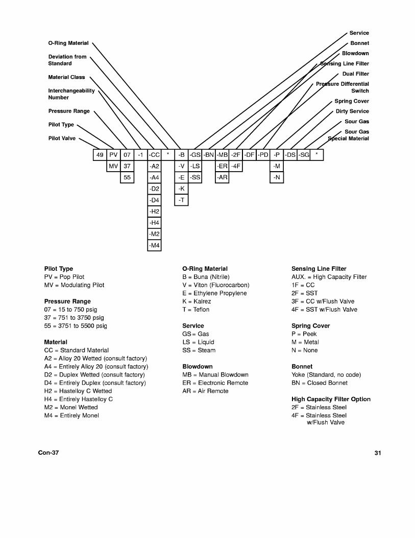
The CONSOLIDATED® Modular Pilot Valve (MPV) is
designed to provide reliable performance characteristics and
stable operation within a pressure range of 15 to 3750 psig.
*Source: ASME Code, Section VIII - Div. I, Paragraph UG-126.
B. Pilot Valve Introduction
Standard pilot construction consists of 316SS parts with nitrile
O-Rings and nitrile diaphragms (only 01 and 07 classes)
with Teflon based seals throughout. Alternate materials can be provided by contacting the factory.
Pilot Valve Features
One pilot fits all 4900-1main valves
Standard O-Ring seals
Superior seat tightness
Accurate adjustment of blowdown and set point
Positive closure after blowdown
Reduces icing and clogging
Dual pilots
Dual filters
Field test connection
Remote sensing
Optional sensing line filter
Backflow preventer
Manual blowdown
Pressure differential switch
External blowdown adjustments
Adjustable Blowdown
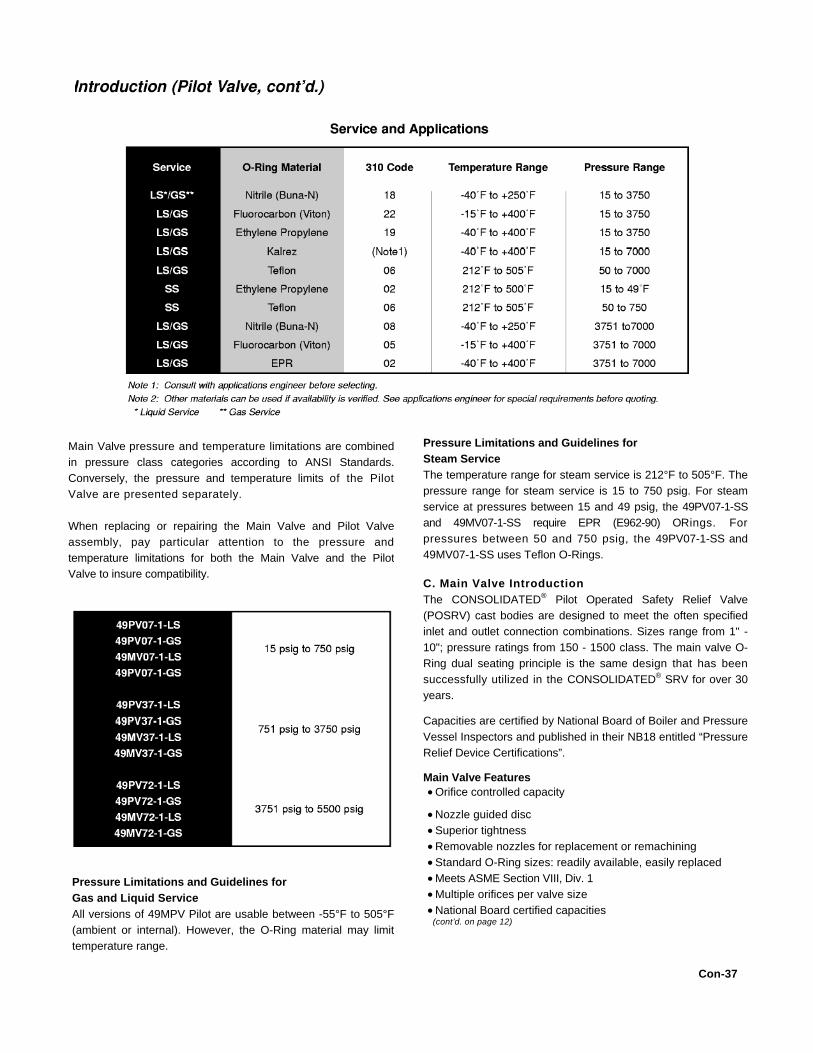
Pressure Limitations and Guidelines for
Steam Service
The temperature range for steam service is 212°F to 505°F. The
pressure range for steam service is 15 to 750 psig. For steam
service at pressures between 15 and 49 psig, the 49PV07-1-SS
and 49MV07-1-SS require EPR (E962-90) ORings. For
pressures between 50 and 750 psig, the 49PV07-1-SS and
49MV07-1-SS uses Teflon O-Rings.
C. Main Valve Introduction
The CONSOLIDATED® Pilot Operated Safety Relief Valve
(POSRV) cast bodies are designed to meet the often specified
inlet and outlet connection combinations. Sizes range from 1" -
10"; pressure ratings from 150 - 1500 class. The main valve O-
Ring dual seating principle is the same design that has been
successfully utilized in the CONSOLIDATED® SRV for over 30
years.
Capacities are certified by National Board of Boiler and Pressure
Vessel Inspectors and published in their NB18 entitled “Pressure
Relief Device Certifications”.
Main Valve Features Orifice controlled capacity
Nozzle guided disc
Superior tightness
Removable nozzles for replacement or remachining
Standard O-Ring sizes: readily available, easily replaced
Meets ASME Section VIII, Div. 1
Multiple orifices per valve size
National Board certified capacities (cont’d. on page 12)
Con-37
Main Valve pressure and temperature limitations are combined
in pressure class categories according to ANSI Standards.
Conversely, the pressure and temperature limits of the Pilot
Valve are presented separately.
When replacing or repairing the Main Valve and Pilot Valve
assembly, pay particular attention to the pressure and
temperature limitations for both the Main Valve and the Pilot
Valve to insure compatibility.
Pressure Limitations and Guidelines for
Gas and Liquid Service
All versions of 49MPV Pilot are usable between -55°F to 505°F
(ambient or internal). However, the O-Ring material may limit
temperature range.


The O-Ring retainer has two machined slots in the upper
beveled edge, allowing system pressure to reach the
chamber behind the O-Ring. This exerts pressure against a
specially curved metal seating surface on valve nozzle. The O-
Ring seat seal design maintains a greater degree of
tightness because the increasing operating pressure works to
force the O-Ring against the metal seat.
When the valve opens, there is no pressure build-up in the O-
Ring chamber as the slots vent the pressure to a lower pressure
area.
This design features a secondary metal-to-metal seat which
becomes effective if O-Ring integrity is lost. The beveled seat
and disc guide the O-Ring into position, eliminating rubbing and
abrasion.
12
A. Operational Description for the 4900 Series Type 49
PV Pilot (PV Valve Closed)
System pressure from the main valve inlet is fed to the dome by
the pilot through interconnecting tubing. This equalizes the
pressure on the top of the disc with inlet pressure on the
seating surface (bottom) of the disc. Since the area of the top of
the disc is larger than the area of the seating surface, the
differential area results in a net downward force, keeping the
main valve tightly closed.

Con-37
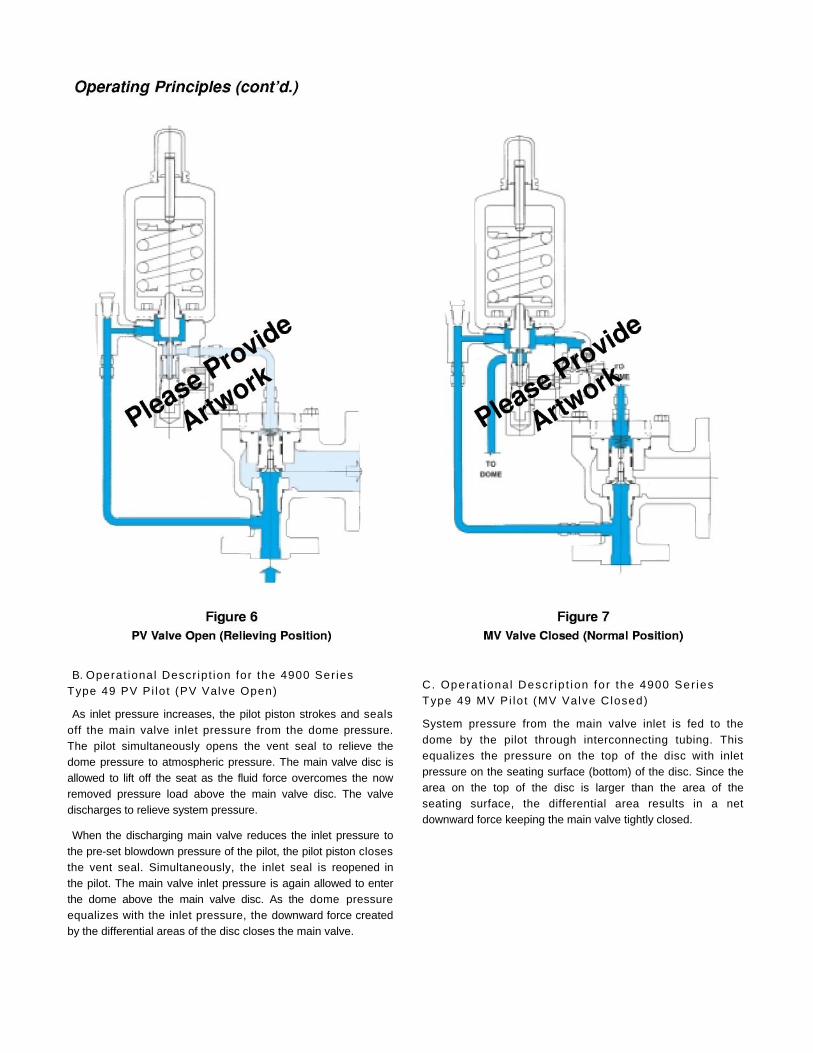
B. Operat ional Descr ipt ion for the 4900 Ser ies
Type 49 PV Pi lot (PV Valve Open)
As inlet pressure increases, the pilot piston strokes and seals
off the main valve inlet pressure from the dome pressure.
The pilot simultaneously opens the vent seal to relieve the
dome pressure to atmospheric pressure. The main valve disc is
allowed to lift off the seat as the fluid force overcomes the now
removed pressure load above the main valve disc. The valve
discharges to relieve system pressure.
When the discharging main valve reduces the inlet pressure to
the pre-set blowdown pressure of the pilot, the pilot piston closes
the vent seal. Simultaneously, the inlet seal is reopened in
the pilot. The main valve inlet pressure is again allowed to enter
the dome above the main valve disc. As the dome pressure
equalizes with the inlet pressure, the downward force created
by the differential areas of the disc closes the main valve.
C. Opera t iona l Descr ip t ion fo r the 4900 Ser ies
Type 49 MV Pi lo t (MV Valve Closed)
System pressure from the main valve inlet is fed to the
dome by the pilot through interconnecting tubing. This
equalizes the pressure on the top of the disc with inlet
pressure on the seating surface (bottom) of the disc. Since the
area on the top of the disc is larger than the area of the
seating surface, the differential area results in a net
downward force keeping the main valve tightly closed.

14
of pressure remains in the dome. This pressure is
controlled by the differential area in the modulator. Since the
dome pressure has not been dropped to atmospheric pressure,
the main valve only partially opens at the set point. The
modulator piston will remain closed until the main valve disc is
forced into higher lift by increasing inlet pressure. As this
occurs, the modulator piston may relieve further pressure from
the dome as necessary to achieve the required main disc lift
within 10% overpressure.
MV Valve Fully Open (Full Relieving Position)
As the inlet pressure increases further, the net upward force on
the main valve disc increases, allowing the main valve to relieve
more pressure. The disc obtains full lift (full capacity) within 10%
of set pressure.
When the discharging valve reduces the inlet pressure to the
pre-set blowdown pressure of the pilot, the pilot piston closes
the vent seal. Simultaneously, the inlet seal is reopened in
the pilot. The main valve inlet pressure is again allowed to enter
the dome above the main valve disc. As the dome pressure
equalizes with the inlet pressure, the downward force created by
the differential areas of the disc closes the main valve.
VI. General Maintenance
A. Restoring Safety
Appropriate service and repair are important to safe, reliable
operation of all valve products. Restoration to original quality
and manufacturing specifications will accomplish the desired
results. Procedures developed by Dresser as described in the
applicable Installation and Maintenance Manual, when correctly
applied, will be effective.
B. General Planning
A 12 month maintenance interval is recommended for general
service conditions. For severe service applications, a 3 to 6
month inspection and testing interim may be more appropriate.
The specific plant’s operating and service history will better
determine this frequency. Dresser encourages preventive
maintenance.
The 4900-3 series Pilot Operated Safety Relief Valve (POSRV) is
easily maintained. Normal maintenance usually involves:
Removal of pilot valve from main valve Disassembly
Cleaning Component Inspection
Parts Replacement as Needed
Reassembly
Setting, Testing and Resealing the Valve
D. Operational Description for the 4900 Series
Type 49 MV Pilot (MV Valve Open)
MV Valve Modulating (Partial Relieving Position)
As inlet pressure increases, the pilot piston strokes and seals
off the main valve inlet pressure from the dome pressure.
The pilot simultaneously opens the vent seal to relieve the dome
pressure to the bottom of the modulator piston. The modulator
piston has a differential area with the smaller area being on top
of the modulator piston. The top of this piston always sees the
main valve inlet pressure. When the dome pressure is applied to
the bottom of the modulator piston, there is a net upward force.
This is due to both pressures being equal (at this point), and the
lower area is larger than the upper area. The modulator
relieves the pressure from the dome to the atmosphere until
force from the inlet pressure on top of the modulator piston is
sufficient to move it to the closed position. A certain amount

General Maintenance (cont’d.) VII. Maintenance of
Occasionally, remachining the seat bushing may Main Valve
be necessary to extend the service life of the
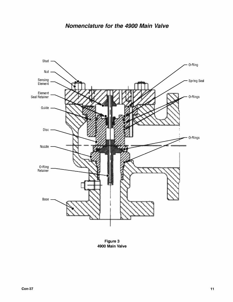
valve. Keep all parts for each valve separated to A. Disassembly of Main Valve
ensure replacement in the same valve. (refer to Figure 3 for Main Valve nomenclature)
C. Removal of Pilot Valve 1. Loosen and remove the cap screws
from Main Valve and the cover plate.
1. Loosen the cap screws and remove the 2. Remove the disc assembly by lifting up
pilot from the coverplate. on the disc and using the small threaded
hole and an eyebolt of the same size and 2. Mark the coverplate and the pilot and thread pitch.
base for ease of assembly.
3. Remove the guide by lifting straight up
3. Remove the spring shield (refer to out of the base.
Figure 3). 4. Remove the sensing retainer nut.
4. Loosen the 4 socket cap screws and remove the pilot from the coverplate. 5 For valves with separate retainer and
sensing tube, remove the retainer from
5. Remove the inlet spool from the inlet port. the disc and then remove the tub
6. Remove the inlet shuttle guide from the 6. Remove all seals and O-Rings inlet port with the flanged end outward. 7. Valve is now ready for cleaning and
7. Remove the inlet shuttle seat from the inspection. inlet bore of the pilot. The counterbore should be facing out. B. Nozzle Removal
For rework or replacement, remove the nozzle
from the base by unscrewing counterclockwise
with the appropriate socket or spanner wrench
shown in Figure 10 and Table 1. This applies to
all main valve sizes except the 8 and 10 inch full
bore valves. The latter are disassembled by
removing the four restraining bolts, inserting two
eyebolts (.625 - 11 unc) 180°apart, and pulling
the nozzle out.
C. Cleaning the Main Valve
Parts are to be free of any oil or grease except for
lubrication as specified in this instruction.
Cleaning agents used should be such that
effective cleaning is assured without injuring the
surface finishes or material properties of the part.
Acceptable cleaning agents include
demineralized water, non-phosphate detergent,
acetone or isopropyl alcohol. Parts must be
blown dry or wiped dry after cleaning.

If you are using cleaning solvents, take
precautions to protect yourself from potential
danger from breathing fumes, chemical burns, or
explosion. See the solvent’s Material Safety Data
________ Sheet for safe handling
recommendations and equipment.

Maintenance of M.V. (cont’d.) It is not recommended to “sand blast” internal
parts as it can reduce the dimensions of the
parts. The base and cover plate may be sand
blasted with care not to erode internal
surfaces, or damage machined surfaces.
D. Main Valve Inspection and Part
Replacement
1. After main valve disassembly, visually
examine the condition of the parts.
2. Check for galling or scratch marks on the
disc OD and guide ID.
3. Examine the top seating surface of the
nozzle for cuts or deformity.
4. Inspect the general condition of base and
cover plate for cracks or holes.
5. Check condition of the O-Ring retainer,
spring, studs and nuts. Replace as
needed.
6. Clean all parts. Inspect guiding and seating
surfaces for damage and wear.
E. Main Valve Maintenance Steps
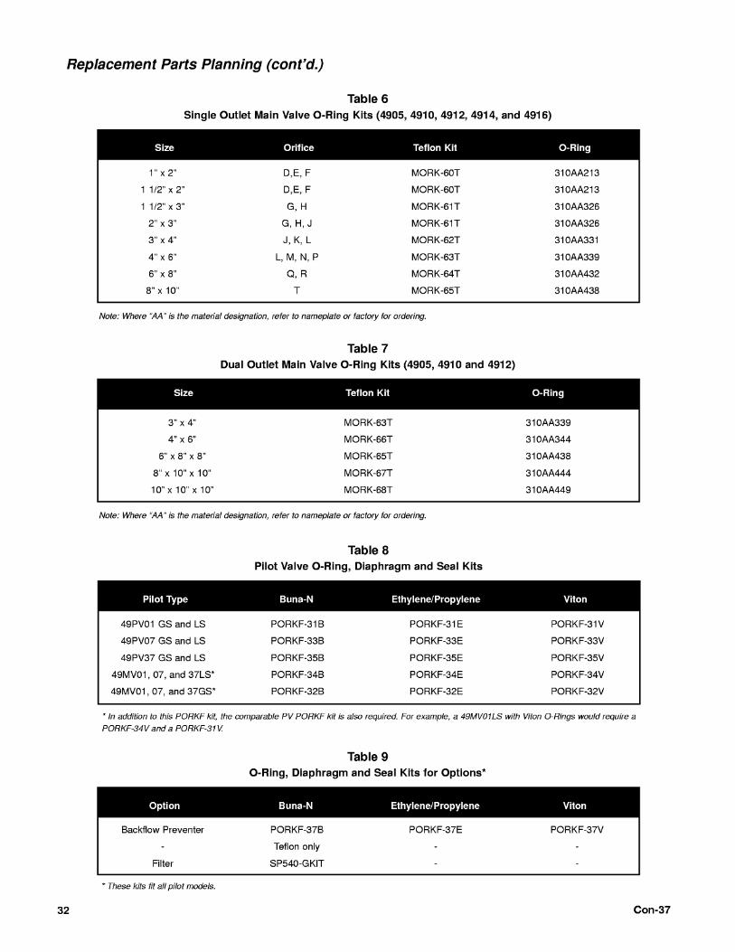
1. Remove and discard all O-Rings, seals
and filter elements. Replace with new parts.
Replacement O-Rings and seal kits are
detailed in Tables 6-9.
2. The nozzle seat can be restored by
machining, if required. Critical dimensions
that MUST be maintained are shown in Figure
11 and Table 2.


Maintenance of Main Valve (cont’d.)
F. Main Valve Lubrication
1. Lightly lubricate all O-Rings with Silicone Grease as
provided in the kit.
2. Lubricate and Seal pipe threads with a Teflon thread
compound such as Dresser SP-364-AB pipe sealant or
Teflon tape.
3. Use nickel based anti-seize compound to lubricate the
threads or bearing surfaces on the cover plate stud bolts or
capscrews.


VIII. Assembly of Main Valve A. Nozzle Installation
Install nozzle O-Ring into groove in nozzle. Install nozzle into
base with the appropriate wrench and torque to the value shown
in Table 3, below.
B. Disc Sub-Assembly
1. Install the seat seat O-Ring in the disc groove and
position the O-Ring retainer onto the disc. Install the
retainer or retainer screws and tighten to the torque values
listed in Table 4a.
2. For valves with separate retainer and sensing tube,
assemble the tube to the retainer before attaching to the
disc. Insert the tube through the retainer and attach using
the hex nut. Torque to 25 ft/lbs ± 5 ft/lbs.
3. Insert an O-Ring into the O-Ring groove of the sensing
retainer nut. Thread the nut into the top of the disc, being
careful not to dislodge the O-Ring. Torque to 300 in/lbs ±
5 in/lbs.
Note: For Teflon seat O-Rings, heat to 300°F for 10 minutes
before installation. Take care to prevent burns to your
fingers.
C. Disc to Guide Seal
1. For Teflon seals, make sure of the integrity of the Teflon seal
and seal springs. Install energized seal on disc outside
diameter. It must be installed with the exposed spring facing
upwards. Install the cut guide ring(s) on disc outside diameter.
Stagger the cut locations on the backup rings 180° apart if two
rings are required.
2. For O-Ring seals, install the O-Ring onto the disc,
locating it in the groove below the omni seal groove.
Note: For valve sizes shown in the following subsections
D and E, “Guide and Disc Assembly”, and for set
pressures below 50 psig, remove the spring in the Teflon
seal before installing.
D. Guide and Disc Assembly
(for D, E, F, G, H, J, K and 3” L)
1. Make sure the chamfer on the top of the guide is
smooth. If any sharp edges exist, polish the chamfer, since
the seal could be damaged during assembly.
2. Insert the disc assembly into the bottom of guide first.
Continue pushing disc into guide, being careful of not
pinching the guide rings. Push disc in until shoulder of disc
hits bottom of guide.
3. Insert guide/disc assembly into top of base. Push disc in
until the disc is in contact with the seat.
4. Drop O-Ring into top of base and guide. 5.
Install O-Ring into top groove on guide.
6. Thread the sensing element into the bottom of the cover
plate. Torque to 50 ft/lbs ± 5 ft/lbs.

Assembly of Main Valve (cont’d.) 7. Install cover plate such that the vent port and dome
port is on the outlet side of the valve center line.
Carefully lower the cover plate onto the base, making sure
that the sensing element aligns with the retainer nut of the
disc. Install cover plate bolting and torque uniformly,
making sure that there is a uniform gap between the
base and the cover plate. Torque stud nuts or cap screws to
the values shown in Table 4.
E. Guide and Disc Assembly
(for 4"L, M, N, P, Q, R, T, 3"F.B., 4"F.B., 6"F.B., 8"F.B. and
10"F.B.)
1. Make sure the chamfer on the top of the guide is
smooth. If any sharp edges exist, polish the chamfer, since
the seal could be damaged during assembly.
2. Insert guide into top of base.
3. Drop O-Ring into top of base and guide.
4. Insert disc assembly into guide with the O-Ring retainer
going in first. Continue pushing disc into guide, being
careful not to pinch the guide rings. Push disc in until it is
in contact with the seat.
5. Install O-Ring into top groove on guide.
6. Install cover plate such that the vent port and dome
port is on the outlet side of the valve center line.
Carefully lower the cover plate onto the base, making sure
that the sensing element aligns with the retainer nut of the
disc. Install coverplate bolting and torque uniformly,
making sure that there is a uniform gap between the
base and the coverplate. Torque stud nuts or cap screws to
the values shown in Table 4.
IX. Maintenance of Pilot Valve
A. Disassembly of Pilot Valve
Tools Required
vise 3/4" open end wrench
1/2" open end wrench
tool #4995401
1/4" Allen wrench
1-1/2" adjustable wrench
• torque wrench (ft/lbs)
Specific Steps
1. Remove the compression screw cap by turning
counterclockwise.
2. Loosen the two cap screws and remove the
modulator attachment if present.
3. Remove the end of the filter and remove the internal filter
element spring body and O-Rings.
4. Loosen the two cap screws and remove the port adaptor
from the pilot base. Mark the pilot valve base and the
adaptor for reassembly.
5. Remove the field test assembly, using care not to drop
the balls from the ball checks.
6. Remove the backflow preventer, using care not to drop
the ball from the filter.
7. Loosen the compression screw lock nut.
8. Loosen and remove the compression screw and lock nut.
9. If the pilot has a bonnet, remove it by unscrewing it
counterclockwise.
10. Remove the spring and spring washers from the
yoke assembly.
11. Loosen and remove the four cap screws from the yoke
(or bonnet base).
12. Remove the main piston from the base.
13. Using a T-handle groove wrench (part #4995401),
remove insert top counterclockwise. Remove the insert
bottom, seal and O-Ring.
14. Remove the adjuster plug by turning it
counterclockwise and then pulling it gently from the pilot
valve base.
15. Holding the large part of the adjuster plug, remove the
adjuster top by turning counterclockwise.
(continued)
19
Con-37

Maintenance of Pilot Valve (cont’d.)
16. Remove all seal and O-Rings carefully as not to
damage the grooves.
17. The pilot valve is now ready to clean and reassemble
(see reassembly procedure).
B. Disassembly of the Modulator Assembly 1.
Remove the seal and seal wire.
2. Remove socket head cap screws holding the
modulator to the main pilot.
3. Remove and discard the 2 O-Rings between the
modulator and the main pilot.
4. Remove both cap screws from the bottom of modulator.
5. Remove modulator stop from modulator base. This can
be done by rotating the modulator stop enough to be able
to push against the ears on the modulator base to remove
the modulator stop.
6. Remove both O-Rings from modulator stop and discard.
7. Remove modulator piston from the modulator base by
hitting the base on a firm surface. Make sure surface is
clean so that when the piston comes out, the seat does not
hit any object that might damage it.
8. Disassemble the modulator piston by removing the lock
screw.
9. Remove and discard both O-Rings. Be careful not to
bend the lip enclosing medium modulator O-Ring (seat)
during removal of the O-Ring.
10. Discard both Teflon seals.
If you are using
cleaning solvents, take
precautions to protect
yourself from
potential danger from
breathing fumes, chemical burns, or explosion. See the
solvent’s
20
Material Safety Data Sheet for safe handling
recommendations and equipment.
It is not recommended to “sand blast” internal parts as it can reduce
the dimensions of the parts. The base and cover plate may be
sand blasted with care not to erode internal surfaces, or damage
machined surfaces.
D. Inspection and Part Replacement
After the valve has been disassembled, all parts should be
given a visual inspection. Some key areas to check with the
boundaries for reworking parts are listed below.
1. Main Piston - Galling or excessive wear on the small
diameter end where it engages the seals or on the spherical
bearing surface. Any corrosion or pitting. The part can be
polished as long as the outside diameter of the stem remains
at 0.243 ± .001 inches. The stem itself must have a TIR of
0.001 inches along its length.
2. Insert Top - Galling or excessive wear on the inside
diameter that guides the Main Piston. Check for any
corrosion or pitting. Also, check for galling of threads.
3. Insert Bottom - Galling or excessive wear on the inside
diameter that guides the Main Piston. Check for any
corrosion or pitting.
4. Adjuster Top - Galling or excessive wear on the inside
diameter that guides the Main Piston. Check for any
corrosion or pitting. Also, check for galling of threads.
5. Adjuster Bottom - Galling or excessive wear on the inside
diameter that guides the Main Piston. Check for any
corrosion or pitting. Also check for galling of threads.
6. Center Plate - Galling or excessive wear on the outside
diameter that rubs against the yoke. Check for any
corrosion or pitting.
7. Yoke - Galling or excessive wear on the inside diameter
that guides the Main Piston Assembly. Any corrosion or
pitting. Check for any galling on the threads for the
compression screw.
8. Compression Screw - Galling at the spherical bearing
surface or in the thread. Check for any corrosion or
pitting.
9. Spring Washers - Galling at the spherical bearing surface.
Check for any corrosion or pitting.
10. Shuttle Base - Galling or excessive wear in the threads.
11. Shuttle Plug - Galling or excessive wear in the threads.
12. Modulator Stop - Top seating surface for cuts or
deformities. The surface can be lapped if the distance
from the seat to the outside shoulder does not reduce to
less than 0.086 inches.
Con
C. Cleaning the Pilot Valve
Parts are to be free of any oil or
grease except for lubrication as
specified in this instruction.
Cleaning agents used shall be such
that effective cleaning is assured
without injuring the surface finishes
or material properties of the part.
Acceptable cleaning agents include
demineralized water, non phosphate
detergent, acetone and isopropyl
alcohol. Parts must be blown dry or
wiped dry after cleaning.

37

Maintenance of Pilot Valve (cont’d.)
13. O-Ring Retainer - Seating surface for cuts or
deformities. The surface can be lapped if the overall height
of the part does not reduce to less than 0.160 inches.
Also, check the outside diameter for any scratches that
might prevent the O-Ring from sealing.
14. Modulator Piston Bottom - Galling or excessive wear on
the outside diameter that rubs against the modulator base.
Make sure that the lip holding the ORing for the seat is
not deformed. Also, check the outside diameter of the O-
Ring groove for scratches that might cause the O-Ring not
to seal. Check for any corrosion or pitting.
15. Modulator Piston Top - Galling or excessive wear on the
outside diameter that rubs against the modulator base.
Check for any corrosion or pitting.
16. Modulator Base - Galling or excessive wear on any
inside diameter. Any corrosion or pitting.
If any damage listed above is present, the part should be
replaced or repaired per instruction. Other valve parts may be
acceptable with light corrosion, pitting, or minor damage of other
types if it can be determined that it will not affect product
performance. All O-Rings, diaphragms, and seals should be
replaced each time the valve is disassembled.
Refer to Tables 6-9 for a list of O-Ring repair kits.
Recommended spare parts are listed in Table 5.
E. Pilot Valve Lubrication
1. Lightly lubricate all O-Rings except Silicone O-Rings, with
Silicone Grease as provided in the kit.
2. Lubricate and seal pipe threads with a Teflon thread
compound such as Dresser SP-364-AB pipe sealant or
Teflon tape.
3. Lubricate standard threads and bearing points with
fluorolube (GR362) or equivalent.
X. Assembly of Main Pilot 1. Make the adjuster assembly
This assembly consists of.. 1
- Adjuster bottom 1 - Adjuster
top 1 - Teflon seat seal
Specific Steps:
a. Install first small main O-Ring into groove on
adjuster top.
b. Install second small main O-Ring into groove on adjuster
bottom. Install from the opposite end of the square.
Con
37
c. On the same end of the adjuster bottom, place the
Teflon seat seal on top of the adjuster bottom with the
spring facing upwards.
d. Thread adjuster top onto adjuster bottom and tighten
hand tight.
Note: Before wrench tightening adjuster top, unscrew the
pieces and inspect seal in adjuster top. Make sure the
outer lip on seat seal did not flare out during installation. If it
did, check seal guiding chamfer for nicks or burrs and
replace the seal. Repeat above procedure until seal
installs properly. Torque to 27 ft/lbs ± 2 ft - lbs.
Do not install adjuster assembly into main base with
O-Rings installed without wrench tightening adjuster
top and adjuster bottom together. Adjuster top can get
stuck in base.
e. Cycle main piston through Teflon seat seal 10
times.
f. Lightly lubricate both O-Rings. Install assembly into base
with the adjuster top going in first. Rotate the assembly at
the same time as it is being inserted until the threads are
engaged. This helps the O-Rings get by the chamfers and
holes.
g. Continue to thread adjuster assembly into base until it
stops. Do not tighten.
h. Thread the adjuster lock nut onto the adjuster assembly
hand tight.
i. Thread adjuster cap onto adjuster assembly. Hand
tighten. Note: Make sure cap threads freely on adjuster bottom. .
Make the insert assembly.
This assembly consists of: 1
- Insert top 1 - Insert bottom 1
- Teflon seat seal 1 - Small
main O-Ring
Specific Steps:
a. Press Teflon seat seal into groove on the insert bottom.
Make sure spring is facing upwards.
b. Install insert top over insert bottom with the seal side
going in first.
c. Lightly lubricate O-Ring groove now formed by the two
insert parts. This lubrication is used to hold the ORing in
place when it is being inserted into base.
d. Place small main O-Ring into groove.
e. As shown in Figure 6, turn insert assembly over and
thread into base with T-handle groove wrench (part
#4995401.) Tighten wrench tight. Make sure milled slot is
facing up. (continued)
21

Con-37 23
Assembly of Main Pilot (cont’d.) f. Cycle main piston through Teflon seat seal 10 times. 3.
Place large O-Ring in groove on top of base. 4. Install the
Teflon seal into the yoke or top plate.
For Low pressure: 49PV07-T
Install the low pressure Teflon seal into the low pressure
yoke or top plate. The spring should be facing you when
installed.
Next, install the low pressure main piston into the low
pressure yoke or top plate with the spring washer
bearing point going in first. Be careful not to damage the
Teflon seal.
For High Pressure: the 49PV37-T
Install the high pressure Teflon seal into the high pressure
yoke or top plate. The spring should be facing you when
installed.
Next, install the high pressure main piston into the t
pressure yoke or top plate with the spring washer
bearing point going in first. Be careful not to damage the
Teflon seal.
5. Install the main piston and yoke or top plate assembly into
the base by inserting small diameter end of piston through
insert assembly. Line up the yoke arms with the dome port and
the inlet port.
6. Insert the four cap screws through the yoke or top plate
and thread into the main base. Tighten to 300 in-L.B.F. (± 30 in-
L.B.F.).
7. Thread lock nut onto compression screw.
8. Thread compression screw into top of yoke or bonnet until
the bearing point begins to protrude through the yoke or
bonnet.
9. Place spring washers on the ends of the spring. There is
not a top or bottom to the top or bottom spring washer.
10. Place spring and spring washer assembly on top of main
piston for valves with yokes. Hold this assembly in place while
turning compression screw down to the top spring washer.
For valves with bonnets, install the bonnet over the spring and
washer assembly. Thread the bonnet onto the top plate.
Tighten wrench tight. Install and tighten lock screws.
11. Tighten compression screw lock nut wrench tight.
XI. Assembly of Field Test Fitting 1. Insert the field test filter or guide into the field test fitting
openings of the body.
2. Insert a ball seat O-Ring into the field test fitting seat ring
counterbore.
3. Insert the field test O-Ring seal into the pilot base.
4. Position the pilot base with the field test fitting opening
vertical. Insert the ball check ball into the filter or guide.
5. Thread the field test fitting body into the pilot base.
Torque the fitting to 50 ft/lbs.

Con-37 23
XII. Assembly of Gas or Liquid Modulator
1. Make the modulator piston assembly.
This assembly consists of..
1 - Modulator piston top
1 - Modulator piston bottom 1 -
O-Ring retainer 1 - Lock screw
1 - Small modulator 0-ring 1 -
Teflon inlet seal 1 - Teflon
balance seal 1 - Medium modulator O-Ring
Specific Steps:
a. Install Teflon inlet seal into groove on modulator piston top.
Be sure to have the spring in the seal facing up.
Note: Make sure that the proper service is stamped on the
top of the modulator piston top.
b. Install medium modulator O-Ring into groove on
modulator piston bottom.
c. Turn modulator piston bottom over and place small
modulator O-Ring into inner groove.
d. Install Teflon balance seal onto modulator piston bottom in
outer groove. Make sure spring is facing down.
e. Insert modulator piston top into modulator piston bottom
through the side with the small modulator ORing and the
Teflon balance seal.
f. Turn assembly over and install O-Ring retainer. The
chamfered outside diameter goes in first.
g. Thread lock screw through O-Ring retainer into
modulator piston top. Tighten 40 in/lbs ± 5 in/lbs.
2. Lubricate Teflon seals before inserting into modulator base.
Note: Make sure that the proper service is stamped on the top
of the modulator base and it matches what is stamped on
modulator piston top.
3. Insert modulator piston assembly into modulator base with the
modulator piston top going in first. Push piston in with thumbs until
it stops. There will be some resistance due to the Teflon seals
compressing to fit into the bore of the modulator base. If necessary
for installation, insert the proper wrench into the lock screw. Lightly
tapping the wrench with a hammer will force the piston into the
modulator base.
4. Install both large modulator O-Rings into grooves on
modulator piston stop.
5. Insert modulator stop into modulator base with the seat going
in first. Make sure the side hole in the modulator stop is facing
towards the flat side of the modulator base.
6. Thread the cap screws through the modulator stop into the pilot
modulator. Tighten to 365 in/lbs ± 30 in/lbs.
7. Install the modulator.
a. Remove pipe plug on flat modulator surface of main
base. Check to verify that no Teflon tape has been left in
vent port or the port above it.
b. Place two small modulator O-Rings into grooves on flat
surface of main pilot.
c. Attach modulator to main base with two hollow head cap
screws with 95 in/lbs ± 10 in/lbs of torque.
XIII. Reassembly of Pilot to the Main Valve
A. Installation of the Pilot
1. For the 49PV07-T and the 49MV07-T:
a. Insert O-Rings in the inlet sensing port, dome port
and vent port ring grooves of the pilot base.
b. Insert the inlet shuttle seat into the inlet bore of the
pilot. The counterbore should be facing out.
c. Inset the inlet shuttle guide into the inlet port with
the flanged end outward.
d. Align the inlet port, dome port and vent port in
the main valve coverplate. Care must be taken to
insure that the shuttle guide and O-Rings stay in
place.
e. Bolt the pilot to the coverplate using the 4 socket
head cap screws specified on the bill of material.
Torque to 40 ft/lbs ± 5 ft/lbs.
2. For the 49PV07-1, 49PV37-1, 49MV07-1 and
49MV37-1:
a. Insert O-Rings in the inlet sensing port, dome port
and vent port ring grooves of the pilot base.
b. Place an O-Ring in the O-Ring shoulder of the
small end of the inlet spool.
c. Insert the inlet spool into the inlet port with the
flanged end outward.
d. Align the inlet port, dome port and vent port of
the pilot with the matching ports in the main valve
coverplate. Care must be taken to insure that the
shuttle guide and O-Rings stay in place.
e. Bolt the pilot to the coverplate using the 4 socket
head cap screws specified on the bill of material.
Torque to 40 ft/lbs ± 5 ft/lbs.

Reassembly, Pilot to Main Valve (cont’d.) B. Assembly of the Backflow Preventer
(refer to Figure 1)
1. Insert a ball seat O-Ring into the pilot base seat ring
counter bore at the bottom of the backflow preventer fitting
opening.
2. Insert the backflow preventer ball check guide into the
pilot base. The end closest to the cross-drilled holes
must go in first.
3. Insert a ball seat O-Ring into the backflow preventer
fitting seat ring counterbore.
4. Insert the two backflow fitting O-Ring seals into the
pilot base, locating them on the seal shoulders as
shown in Figure 1.
5. Position the pilot base with the backflow preventer fitting
opening vertical. Insert the ball check ball into the guide.
6. Thread the backflow preventer into the pilot base.
Torque the fitting to 50 ft/lbs.
C. Assembly of the External Filter
1. Insert O-Rings into the two .375 diameter x .055 deep
counterbores of the external filter port of the pilot base.
2. Insert an O-Ring into the counterbore at the filter base
bolt hole.
3. Assemble the filter base to the pilot base using the
filter bolt reference on the b/m. The 1/4-18NPT thread in
the filter base must be facing toward the pilot base inlet
flange face. Torque the bolt to 35 ft/lbs ± 5 ft/lbs.
4. Screw the filter tie bolt into the filter base. The end with
the drilled and cross-drilled hole goes in the filter base.
Screw it all the way in until it contacts the filter bolt, then
back off 1/4 turn.
5. Install the filter element over the tie bolt and onto the
raised filter element guide of the filter base.
6. Install a filter sleeve O-Ring seal over the filter sleeve
guide shoulder of the filter base.
7. Install the filter sleeve to the filter base.
8. Install a filter sleeve O-Ring seal over the filter sleeve
guide shoulder of the filter end cap.
9. Thread the filter end cap onto the filter tie bolt. Tighten
until metal-to-metal make up with the guide sleeve is
obtained.
XIV. Pilot Valve Testing
A. General Testing
The pilot valve opening and closing pressure must be calibrated
prior to its assembly onto the main valve. Failure to do this can
cause incorrect blowdown readings, but if the valve is to be
tested on the pressure vessel, it can successfully be
calibrated and tested for set pressure and blowdown.
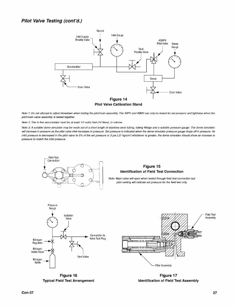
The pilot test stand should consist of the equipment listed
below (refer to Figure 14 for recommended set up). All
equipment must be rated for at least 3750 (264 kg/cm2) psig
pressure.
1. suitable pressure source with regulator 2. 1/2 cubic foot (14 liter) inlet side accumulator 3.
1/30 cubic foot (1 liter) dome simulator 4. inlet and
dome pressure gauges 5. inlet supply throttle valve
6. inlet supply vent/throttle valve
7. inlet supply and dome simulator pressure gauges
The inlet accumulator and dome simulator should be fitted
with a drain valve at the lowest point in the vessel to allow
draining moisture before testing.
B. Definitions and Guidelines
• Set Point: This is the point where vent pressure is felt
from port.
• Closing Point: This is the point where dome pressure
begins to reload.
Blowdown: Set point minus closing point.
• Notch: Any peak or valley on bottom of main pilot which
is used for adjustment.
Leakage will be checked for a one-minute interval. Pilots
with Teflon O-Rings (for use on steam) may leak on air
test.
Con-37

Pilot Valve Testing (cont’d.)
C. Calibration and Testing Procedure
1. Remove adjuster cap and loosen the adjuster plug lock nut. 2.
Proceed with the initial setting of seats. a. Turn adjuster into base until it stops. Turn out 1 turn.
b. Adjust compression screw to approximately ± 10% of set point
of pilot. Final setting will be done later.
3. Troubleshoot.
a. Make adjustments in 2 notches or less. Match any corner of
the square on the bottom of the adjuster to a notch on the
base.
b. Only turn adjuster when there is less than 125 psig
in dome. Adjustment is usually done when inlet pressure is
at 110% of set pressure.
c. If you experience long blowdown, turn the adjuster out. If
the pilot is flowing and the dome is not dropping at 1% or 1
psig overpressure (whichever is greater), turn adjuster in.
4. Adjust blowdown.
a. Lower inlet pressure so that inlet and dome
pressures are equal (approximately 90% of set
pressure).
b. Slowly increase pressure to note the set point.
c. Increase inlet pressure to 1% or 1 psig above set point
(whichever is greater), and hold for a couple of seconds to
make sure dome pressure is dropping. If dome pressure is
dropping, continue to increase to 10% over pressure or 3
psig (whichever is greater). Dome pressure should drop to
0 psig. If dome pressure is not dropping, adjust as noted in
the preceding Step 3, "Troubleshooting".
d. Slowly drop inlet pressure to note the closing point. e.
Use the following guidelines when setting blowdown:
For Gas Service: Set pressure is 15 to 75 psig - 0 to 1.5 psig
blowdown Set pressure is 76 to 750 psig - 0% to 2% blowdown Set pressure is 751 to 3750 psig - 0% to 3% blowdown
For Liquid Service: Set pressure is 15 to 30 psig - 1 to 3 psig blowdown Set pressure is 31 to 75 psig - 2 to 4 psig blowdown Set pressure is 76 to 3750 psig - 3% to 6% blowdown.
Con-37
For 49MV-T: Set at 0% to 1% below set pressure or 1 psig,
whichever is greater.
For example, if the set pressure equals 150 psig on gas, the
following valves would be set at:
49PV07-T = 147.0 psig 49MV07-T = 148.5 psig Closing point =
144.1 psig Closing point = 145.5 psig
Pilot 0 BPM = 144 psig Pilot 0 BPM = 144 psig Pilot < 40
BPM = 165 psig Pilot 0 BPM = 165 psig
6. After adjustments have been made, tighten lock nut on
compression screw and tighten adjuster cap to secure settings.
7. Re-Verify Settings.
a. Lower inlet pressure so that inlet and dome pressures are
equal (approximately 90% of set pressure).
b. Slowly increase pressure to verify that pilot is tight (0
BPM) at 4% below set point or 2 psig, whichever is greater.
c. Increase inlet pressure to 1% or 1 psig above set point,
whichever is greater, and hold for a couple of seconds to make
sure dome pressure is dropping. If dome pressure is dropping,
continue to increase to 10% over pressure or 3 psig, whichever
is greater. Dome pressure should drop to 0 psig. If dome
pressure is not dropping, adjust as noted in the preceding Step
3, "Troubleshooting". Retest beginning with Step 7a, above.
d. Check rate of leakage from pilot at 10% above unit
ticket set point. It should be less than 40 BPM.
e. Slowly drop inlet pressure to note the closing point. 25
f. If blowdown adjustments are necessary, increase inlet
pressure to release dome pressure to less than 125 psig.
Make adjustments and re-test as outlined in the preceding
Step 3, "Troubleshooting".
g. If adjustments are not necessary, continue with Step 5.
5. Adjust compression screw for set pressure without modulator
attached.
For 49PV-T: Set at 1% to 2% below set pressure or 1 psig,
whichever is greater.
Note: If the 49PV-T is piped to the outlet, increase the set
pressure mentioned above according to the following table.
Pilot Valve Testing (cont’d.)
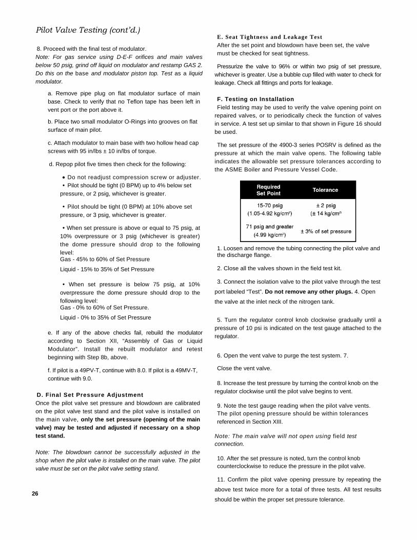
8. Proceed with the final test of modulator.
Note: For gas service using D-E-F orifices and main valves
below 50 psig, grind off liquid on modulator and restamp GAS 2.
Do this on the base and modulator piston top. Test as a liquid
modulator.
a. Remove pipe plug on flat modulator surface of main
base. Check to verify that no Teflon tape has been left in
vent port or the port above it.
b. Place two small modulator O-Rings into grooves on flat
surface of main pilot.
c. Attach modulator to main base with two hollow head cap
screws with 95 in/lbs ± 10 in/lbs of torque.
d. Repop pilot five times then check for the following:
Do not readjust compression screw or adjuster.
• Pilot should be tight (0 BPM) up to 4% below set
pressure, or 2 psig, whichever is greater.
• Pilot should be tight (0 BPM) at 10% above set
pressure, or 3 psig, whichever is greater.
• When set pressure is above or equal to 75 psig, at
10% overpressure or 3 psig (whichever is greater)
the dome pressure should drop to the following
level: Gas - 45% to 60% of Set Pressure
Liquid - 15% to 35% of Set Pressure
• When set pressure is below 75 psig, at 10%
overpressure the dome pressure should drop to the
following level: Gas - 0% to 60% of Set Pressure.
Liquid - 0% to 35% of Set Pressure
e. If any of the above checks fail, rebuild the modulator
according to Section XII, “Assembly of Gas or Liquid
Modulator”. Install the rebuilt modulator and retest
beginning with Step 8b, above.
f. If pilot is a 49PV-T, continue with 8.0. If pilot is a 49MV-T,
continue with 9.0.
D. Final Set Pressure Adjustment
Once the pilot valve set pressure and blowdown are calibrated
on the pilot valve test stand and the pilot valve is installed on
the main valve, only the set pressure (opening of the main
valve) may be tested and adjusted if necessary on a shop
test stand.
Note: The blowdown cannot be successfully adjusted in the
shop when the pilot valve is installed on the main valve. The pilot
valve must be set on the pilot valve setting stand.
26
E. Seat Tightness and Leakage Test
After the set point and blowdown have been set, the valve
must be checked for seat tightness.
Pressurize the valve to 96% or within two psig of set pressure,
whichever is greater. Use a bubble cup filled with water to check for
leakage. Check all fittings and ports for leakage.
F. Testing on Installation
Field testing may be used to verify the valve opening point on
repaired valves, or to periodically check the function of valves
in service. A test set up similar to that shown in Figure 16 should
be used.
The set pressure of the 4900-3 series POSRV is defined as the
pressure at which the main valve opens. The following table
indicates the allowable set pressure tolerances according to
the ASME Boiler and Pressure Vessel Code.
1. Loosen and remove the tubing connecting the pilot valve and the discharge flange.
2. Close all the valves shown in the field test kit.
3. Connect the isolation valve to the pilot valve through the test
port labeled “Test”. Do not remove any other plugs. 4. Open
the valve at the inlet neck of the nitrogen tank.
5. Turn the regulator control knob clockwise gradually until a
pressure of 10 psi is indicated on the test gauge attached to the
regulator.
6. Open the vent valve to purge the test system. 7.
Close the vent valve.
8. Increase the test pressure by turning the control knob on the
regulator clockwise until the pilot valve begins to vent.
9. Note the test gauge reading when the pilot valve vents. The pilot opening pressure should be within tolerances
referenced in Section XIII. Note: The main valve will not open using field test connection.
10. After the set pressure is noted, turn the control knob counterclockwise to reduce the pressure in the pilot valve.
11. Confirm the pilot valve opening pressure by repeating the
above test twice more for a total of three tests. All test results
should be within the proper set pressure tolerance.

Con-37
1. Disassembly: remove plug (located near the valve discharge
flange) from body by unscrewing counterclockwise. Remove
ball and filter.
2. Maintenance and Reassembly a. Remove and discard O-Rings.
b. Clean all parts and inspect for damage and wear.
c. Lubricate O-Rings with silicone grease or equivalent.
d. Reassemble with new O-Rings (refer to Table 9, ORing
kit information for options).
XV. Backflow Preventer Option
When a pilot operated relief valve is not vented directly to
atmosphere, it is possible to build up a back pressure in the
discharge line. This is typical in applications where several valves
manifold into a common discharge header. Should the discharge
line back pressure exceed the valve inlet pressure, it could cause
the main valve piston to lift and allow reverse flow through the
main valve. This trouble can be avoided by use of the Backflow
Preventer optional feature.
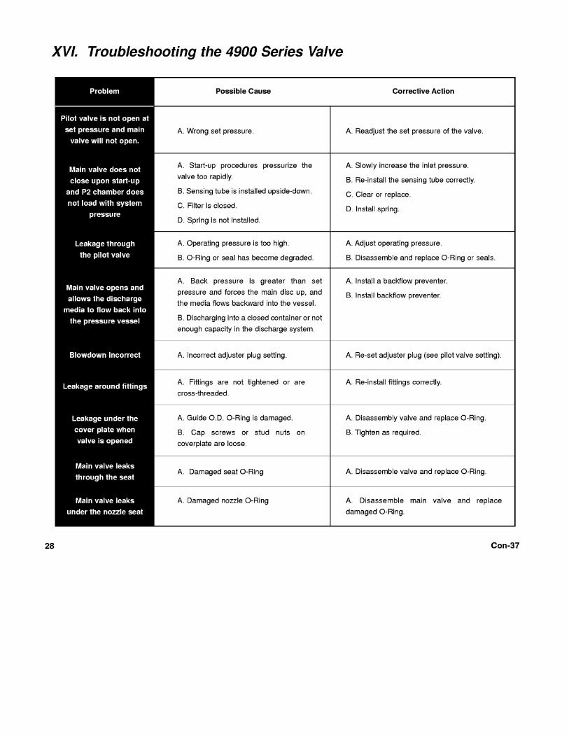

XVII. Replacement Parts Planning
A. Basic Guidelines
The following guidelines should be of assistance in
developing a meaningful replacement parts plan.
1. The total number of valves in service should be
classified by size, type, and temperature class.
2. The parts inventory should be classified by the tendency
to require replacement.
Class I - Most frequently replaced
Class II - Less frequently replaced but critical in an
emergency
3. Parts for the valve types covered by this manual are
classified on Table 5. "Quantity Parts" is the number of parts
or sets which is recommended to achieve a desired
need-probability, as it relates to the total number of
valves in service by size and type. For example, a "Qty.
parts" of 1 for "Valves in service" of 5 means that 1 part
should be stocked for each 5 valves of the same type and
size in service.
4. When ordering replacement parts, please specify in
accordance with applicable nomenclature (see Figures 1-3).
Be sure to state the size, type and serial number of the
valve for which parts are required. When ordering pilot
parts please state specific pilot type (49PV01, 07, 37,
etc.)
For ease of maintenance O-Ring kits are available for
each main valve and pilot type. A stock of these kits should
be kept on hand for maximum operating efficiency. See
Tables 6-9.
B. Identification and Ordering Essentials
When ordering service parts, please furnish the following
information to ensure receiving the correct replacement parts.
Identify valve by the following nameplate data: 1.
Size 2. Type
3. Pressure/Temperature Class Rating
4. Serial Numbers from both main valve and pilot valve
Example: Main Valve - 4910R-3-CC-DA-RF-GS, TL1234M
Pilot Valve - 49PV07-1-CC-B-GS, TL1234P
Con-37
D. Verifying Materials of O-Rings and Seals Kit
coding indicates O-Ring and seals material.
Examples: MORK-60T T=Teflon
B=Buna N PORKF-34E
E=Ethylene/Propylene
PORKF-32V V=Viton
K=Kalrez
29

30 Con-37
Replacement Parts Planning (cont’d.) E. Positive Identification of Main Valve and Pilot
Valve Combinations
POSRV's shipped direct from the factory to the end-user
probably have main valves and pilot valves with identical serial
numbers (S/N's). Those shipped unconnected to the Dresser
Green Tag network may have main valves and pilot valves with
different S/N's. During service and repair, the following
inspection steps will ensure the proper match of main valves to
pilot valves:
1. Record main valve and pilot valve S/N's of original
POSRV's in plant records.
2. Inspect S/N's for agreement with Step 1, after any
disassembly involving removal of pilot valve from main
valve.
3. Make sure the set pressures of the main valve and
pilot valve are identical.
4. Check O-Ring and Seals Kit material code to ensure
they are the same for main valve and pilot valve.
Any discrepancies should be promptly reported to the
appropriate plant authority.
Specify parts required by:
1. Part Name (for Nomenclature, refer to Figures 1- 3) 2.
Part Number (if known) 3. Quantity
Contact Parts Marketing: 1-318-640-2250
In addition, the main valve serial number is stamped on the
top edge of the outlet flange. Be sure to include the one or two
letters preceding the figures in the serial number. Typical valve
nameplates are shown in Figures 18 and 19.

Replacement Parts Planning (cont’d.)
Engineering Instructions

Con-37 33
XVIII. Manufacturer’s Field Service, Training and Repair Program
A. Field Service
Utilities and Process Industries expect and demand service on a moment's notice. CONSOLIDATED' Field Service can be depended upon for prompt response, even in extreme off-hour emergency situations.
Dresser maintains the largest and most competent field service staff in the Industry. Service Engineers are located at strategic points throughout the United States to respond to customer's requirements for service. Each Service Engineer is factory trained and long experienced in servicing Safety Valves. Dresser Service Engineers restore disc and nozzle critical dimensions which affect valve performance and are capable of modernizing valves in the field.
It is highly recommended that the professional talents of a Dresser Field Service Engineer be employed to make final field adjustments during the initial setting of all CONSOLIDATED® POSRV's.
All Field Service Engineer's activities are coordinated from the Alexandria, Louisiana, Field Service Office. Upon receipt of a purchase order number authorizing the trip, the service engineer is dispatched.
Contact: Field Service Dept., Field Service Supervisor, (318) 640-6055.
B. Factory Repair Facilities
The factory at Alexandria, Louisiana maintains a CONSOLIDATED' Repair Center. The Repair Department, in conjunction with the manufacturing facilities, is equipped to perform specialized repairs and product modifications, e.g. butt-weld, bushing replacements, code welding, pilot replacement, etc. Contact: Repair Dept., Mgr. Valve Repair, (318) 640-6057. C. Safety Relief Valve Maintenance Training Rising costs of maintenance and repair in the Utility and Process Industries indicate the need for trained maintenance personnel. Dresser Industrial Valve Operation conducts service seminars that can help your maintenance and engineering personnel to reduce these costs.
Seminars, conducted either at your site, or at our Alexandria, Louisiana manufacturing plant, provide participants with an introduction to the basics of preventive maintenance necessary to minimize downtime, reduce unplanned repairs and increase valve safety. While these seminars do not make "instant" experts, they do provide the participants with "Hands On" experience with CONSOLIDATED' Valves. The seminar also includes valve terminology and nomenclature, component inspection, trouble shooting, setting and testing, with emphasis on the ASME Boiler and Pressure Vessel Code.
For further information, please contact the product Training Manager by fax at (318) 640-6041, or telephone (318) 6406054.


![Safety Recall T53 / NHTSA 17V-543 Certification Label · Please reference Safety Recall T53. Fiat Chrysler Automobiles US LLC Certification Label Dear [Name], This notice is sent](https://static.fdocuments.us/doc/165x107/5e6935056e865859c17081df/safety-recall-t53-nhtsa-17v-543-certification-label-please-reference-safety-recall.jpg)

![Product Safety Signs and Labels · 7 Safety sign and label colors ... ANSI Z535.4 Product Safety Signs and Labels [new in 1991] ANSI Z535.5 Safety Tags and Barricade Tapes ...](https://static.fdocuments.us/doc/165x107/5ae304257f8b9a595d8de20b/product-safety-signs-and-labels-safety-sign-and-label-colors-ansi-z5354-product.jpg)