Produced Water & Environmental Conference TUVNEL ... KANFA Mator.pdf · Produced Water &...
23
31 years experience with produced water technologies in the North sea Produced Water & Environmental Conference TUVNEL , Aberdeen 5-6 June 2013 Jon Berntsen, KANFA Mator AS
Transcript of Produced Water & Environmental Conference TUVNEL ... KANFA Mator.pdf · Produced Water &...
31 years experience with produced water technologies in the North sea
Produced Water & Environmental Conference
TUVNEL , Aberdeen 5-6 June 2013
Jon Berntsen, KANFA Mator AS

31 years. A short time in the history of oil, but technologically?
What was the typical NCS technology in the early 80’s?
CPI (Corrugated Plate Interceptor)
Flotation cells (WEMCO)
Skimmer/separator
What was the typical produced water flow rates?
Fairly low – moderate.
What was the prospects about water flow rates?
Rocketing!

Input data for design and equipment selection
• Characteristics and thereby treatability of produced water prior to treatment depends on:
− the type of fluid to be produced (oil field (saline) or gas field (no saline))
− the effect of choking (generation of small droplets)
− the water flow rate (able to handle high flow)
?

Hydrocyclone
Feed inlet via. tangential ports
Accelerating Helical
Flow Path
Reverse Flow in
Central Core
Dense Phase
Underflow
Light Phase
Overflow
Back - Pressure
Regulation
Advantage:
Handling high flow
Small footprint
Need to:
Understand design
Understand operation

Hydrocyclone: Understand design
Started with Serck Baker 60 mm oil spin Next
37 mm hydrocyclone Next
22 mm hydrocyclone Next
17 mm hydrocyclone Finally
14 mm hydrocyclone
The most promising was the 22 mm hydrocyclone since it provided a true operating
window. The smaller diameters (17mm and 14mm) was difficult to
operate, but showed good performance at one specific pressure drop!
Today’s design with D= 18 – 22 mm is a good choice.

Hydrocyclone: Understand performance
Parallel installation on
offshore platforms.
The shaded illustration
is what the vendors
tried to sell.
The performance is
real life.
PROSEP is the empirical software
we developed to calculate performance

Hydrocyclone: Understand performance
A closer look at the model shows
that flow rate (Q) is influential
for both flow pattern and efficiency.
Experience shows that optimal Q is very
important for good performance!
It is interesting to observe that the industry (suppliers) finally acknowledge
this fact and deliver vessel with multiple chambers to adjust capacity to fit
the actual Q.

Further increase in water production
The rapid increase in produced water production generated new
operational challenges.
• Increased use of corrosion inhibitor (surface active chemical)
• Reduced BS&W to export intensified the use of emulsion breaker
• Increased volume of low pressure produced water (carry over
from separators)
The increased use of production chemicals lead to periods with
difficulties to meet discharge requirements.
The industry grabbed this opportunity to develop something that
could boost the hydrocyclone performance:
Coalescing device(s)/methods
Use of inlet cyclones
It was not only increase in water production but also higher gas flow rates
that challenged the industry.
Higher gas rates and water rates increase problems with foaming in the
separators leading to compressor breakdown.
In an attempt to reduce this problem, inlet cyclones was installed in the
majority of inlet and secondary separators.
The result of this retrofits was EVEN MORE produced water problems!
Coalescence
Separation = Coalescence
Since oil is dispersed in the water as very small droplets there is a demand
that the oil droplets get in contact with each other and are able to coalesce.
One method, might be use of material that promote coalescence (oleophilic
surfaces).
The idea is good and various components is developed, but it did not met
the expectations.
• Produced water contain:
• High volume of solids (clay, silt, scaling products)
• Huge volume of fine dispersed gas bubbles
These coat the surface and inhibit contact with the coalescing material.
• Oliophilic material placed in water become hydrophilic with time.
C-Tour
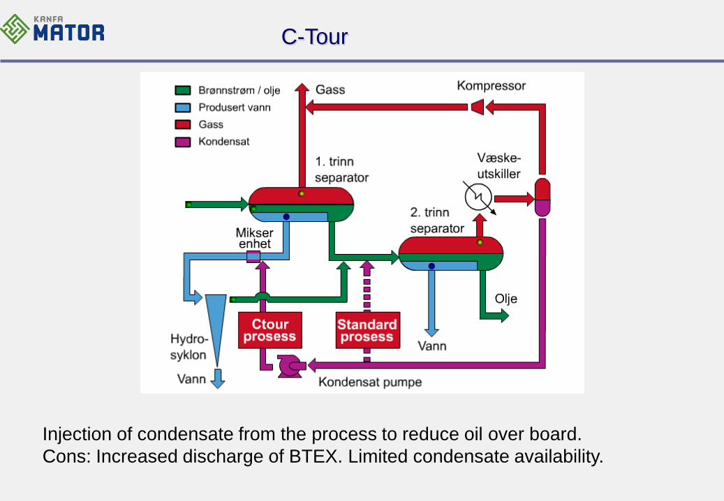
Injection of condensate from the process to reduce oil over board.
Cons: Increased discharge of BTEX. Limited condensate availability.
Compact flotation unit
The oil industry has a long time experience with flotation but current (90’s)
technology represented huge weight and footprint and maintenance.
The development of a vertical column with more efficient design easy to
retrofit entered the marketplace.
CFU is a rather simple technology which resulted in a vast number of
suppliers.
It is normally possible to achieve very good performance, which is even
the history behind horizontal flotation cells (WEMCO’s), but it is easy to
end up with very bad or low performance.

Compact flotation unit
CFU require flotation gas and flocculants for reliable performance.
Produced water contain much particles, typically oil wetted. These particles
sticks to the flocculants together with oil and form a new component which,
over time, clog rejects.
Unfortunately we experience several
units that, periodically, have higher
oil concentration out of the unit than
into the unit !
We have had access to daily lab reports showing a CFU having lower oil
concentration out of the unit compared to into the unit for only
10 days in a 6 months period .

Compact flotation unit
Below are given two illustrations from control room monitor showing levels in
the CFU. This is an installation with two CFU’s in series.
The left illustration show first CFU with clogged reject having only gas in
the vessel. No water level established.
Right illustration show first unit with restriction in reject line. Only gas emerging.
Compact flotation unit
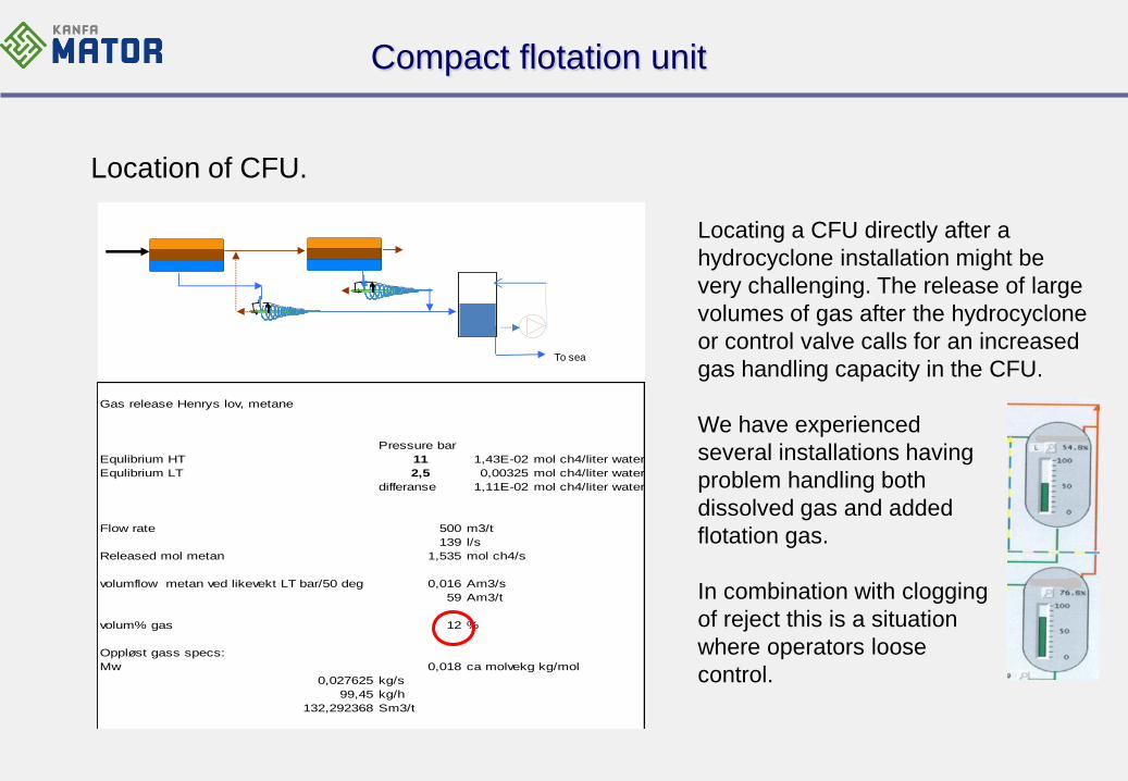
Location of CFU.
To sea
Gas release Henrys lov, metane
Pressure bar
Equlibrium HT 11 1,43E-02 mol ch4/liter water
Equlibrium LT 2,5 0,00325 mol ch4/liter water
differanse 1,11E-02 mol ch4/liter water
Flow rate 500 m3/t
139 l/s
Released mol metan 1,535 mol ch4/s
volumflow metan ved likevekt LT bar/50 deg 0,016 Am3/s
59 Am3/t
volum% gas 12 %
Oppløst gass specs:
Mw 0,018 ca molvekg kg/mol
0,027625 kg/s
99,45 kg/h
132,292368 Sm3/t
Locating a CFU directly after a
hydrocyclone installation might be
very challenging. The release of large
volumes of gas after the hydrocyclone
or control valve calls for an increased
gas handling capacity in the CFU.
We have experienced
several installations having
problem handling both
dissolved gas and added
flotation gas.
In combination with clogging
of reject this is a situation
where operators loose
control.

Handling low pressure produced water
• Low pressure produced water is often more stabilised by particles and chemicals
(lower interfacial tension thereby lower oil droplet coalescence), thereby more
difficult to treat.
• However, treatment systems for low pressure water are often less equipped than
systems for high pressure water → low pressure water has negative influence
on the discharge.
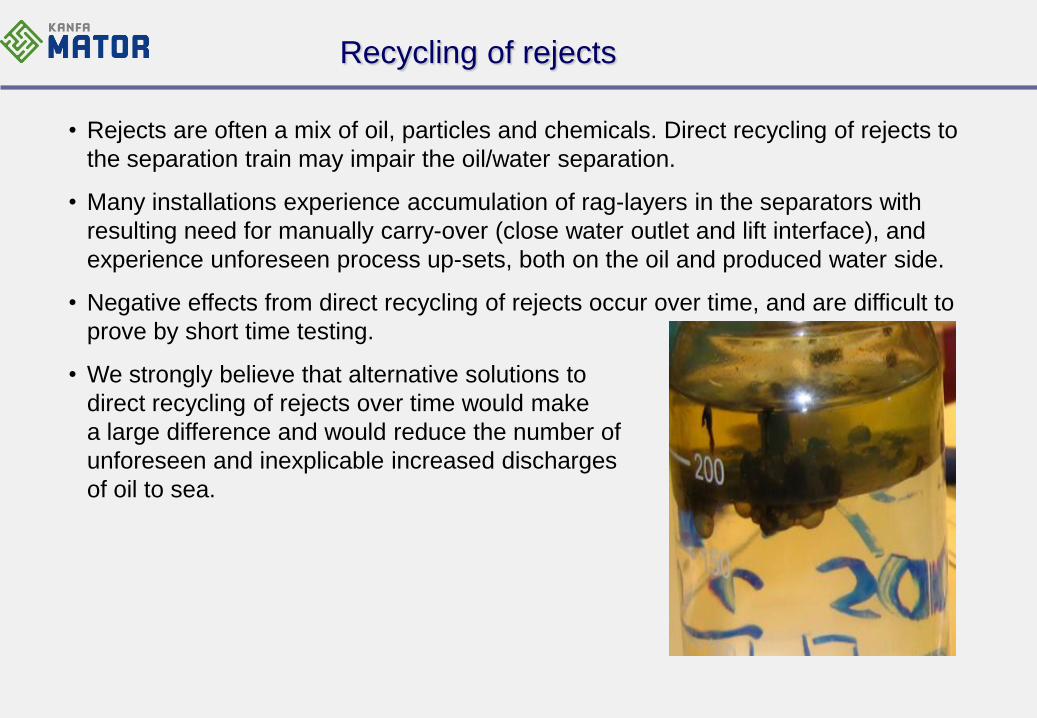
Recycling of rejects
• Rejects are often a mix of oil, particles and chemicals. Direct recycling of rejects to
the separation train may impair the oil/water separation.
• Many installations experience accumulation of rag-layers in the separators with
resulting need for manually carry-over (close water outlet and lift interface), and
experience unforeseen process up-sets, both on the oil and produced water side.
• Negative effects from direct recycling of rejects occur over time, and are difficult to
prove by short time testing.
• We strongly believe that alternative solutions to
direct recycling of rejects over time would make
a large difference and would reduce the number of
unforeseen and inexplicable increased discharges
of oil to sea.
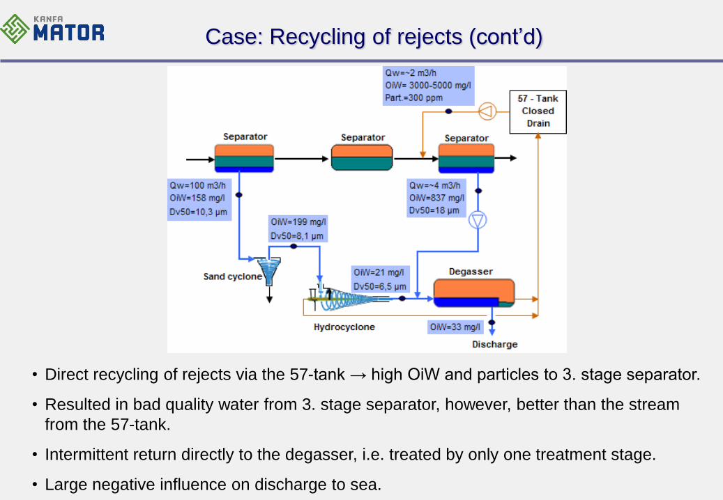
Case: Recycling of rejects (cont’d)
• Direct recycling of rejects via the 57-tank → high OiW and particles to 3. stage separator.
• Resulted in bad quality water from 3. stage separator, however, better than the stream
from the 57-tank.
• Intermittent return directly to the degasser, i.e. treated by only one treatment stage.
• Large negative influence on discharge to sea.

Case: Recycling of rejects (cont’d)
• Build-up of rag-layer in coalescer and
intermittent (on/off) return of bad quality water
with flocculant and particles to 1. stage
separator.
• Periods with control of flocculant injection,
reduced skimming from degasser thereby
reduced recycle, and improved pumping
frequency of water return from coalescer to
1. stage separator.
Online OiW:
Online OiW:

Case: Recycling, but more controlled
• Reject water phase treated by dedicated
centrifuge. Discharge < 10 ppm OiW
• Improved solution for treatment of reject
and low pressure water from different
sources!

Generic production process
Equipment drain
HP separator LP separator Export
Overboard
PWT
system 44:Rejects
57:Closed drains
Export
Overboard
Solids/sludge
Export
Overboard
Solids/sludge
An alternativ treatment system for recycled fluid

An alternativ treatment system for recycled fluid
A major challenge for treatment of reject fluids is particles, typically oil coated
neutral density particles. This situation is frequently experienced on installation
processing high water cut wells.
This situation limits the use of filter, flotation and hydrocyclone technologies.
The only technology that has proven capable to treat such fluid, is centrifuges.
BUT, history tells that the operators are not satisfied. WHY?
The centrifuges are incorrect installed and used
The fluids to be treated are a mix of particles, stable oil droplets and chemicals.
Sometimes it can be low temperature fluids stored in a huge tank.
This situation represents a separation challenge and to be able to handle this
the centrifuge should, at least, have twice the capacity compared to the feed pump!
A very simple role of thumb.

31 years experience with produced water technologies in the North sea
A neutral review of lesson learned:
Hydrocyclone followed by degasser proved performance to less than 10
ppm OiW.
Low pressure water treatment is a challenge, should never be recycled.
Technology available – market not prepared.
Production chemicals challenging but with correct dosage and proper
understanding from operators it might be less a problem.
Lack of process understanding (incorrect location of technology).
Some produced water might need special treatment due to reservoir
specific properties (iron, barium …..) (correct chemical).
Accept that produced water contain lots of particles, many oil wetted.