PROCEDURES • Power Lines - Crane Institute
78
145 PROCEDURES • Power Lines Crane contact with power lines is a major cause of serious injuries and fatalities involving those working with cranes. Overhead power lines must always be considered energized until electrical authorities indicate otherwise. Crane operators and other personnel involved in the operation must not rely on the covering of wires for their protection. Before any work has begun on a job site containing power lines, the utility company must be contacted to determine if it is feasible for the power lines to be: temporarily diverted around the job site; or de-energized and visibly grounded and appropriately marked at the job site location; or for insulating barriers to be erected to prevent contact between the crane, load, and lines. If none of these are feasible, the following steps must be taken to minimize the hazard of electrocution or serious injury as a result of the crane or load contacting energized power lines. • An on-site meeting must be held between management of the project and the owner of the power lines (or a designated representative of the electrical utility) to establish procedures to safely complete the operation. Before work begins, these procedures must be communicated to all personnel involved in the operation – including crane operators, signal persons, and riggers, etc.
Transcript of PROCEDURES • Power Lines - Crane Institute
145
PROCEDURES • Power Lines
Crane contact with power lines is a major cause of serious injuries and fatalities involving those working with cranes. Overhead power lines must always be considered energized until electrical authorities indicate otherwise. Crane operators and other personnel involved in the operation must not rely on the covering of wires for their protection.
Before any work has begun on a job site containing power lines, the utility company must be contacted to determine if it is feasible for the power lines to be: temporarily diverted around the job site; or de-energized and visibly grounded and appropriately marked at the job site location; or for insulating barriers to be erected to prevent contact between the crane, load, and lines. If none of these are feasible, the following steps must be taken to minimize the hazard of electrocution or serious injury as a result of the crane or load contacting energized power lines.
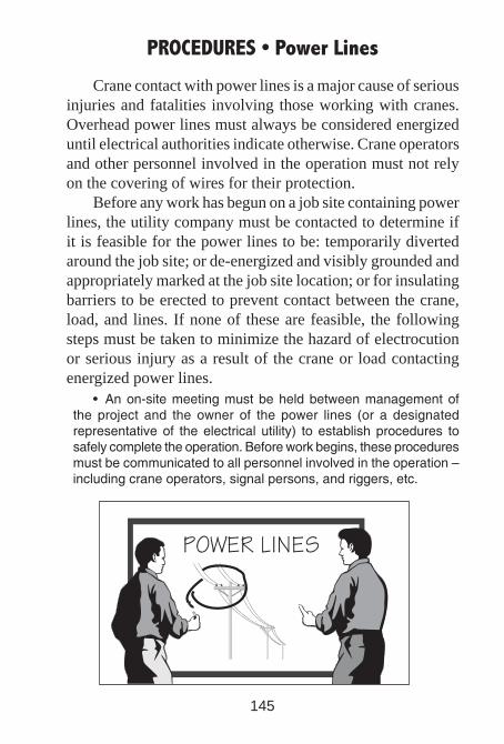
•Anon-sitemeetingmustbeheldbetweenmanagementofthe project and the owner of the power lines (or a designatedrepresentativeof theelectrical utility) to establishprocedures tosafelycompletetheoperation.Beforeworkbegins,theseproceduresmustbecommunicatedtoallpersonnelinvolvedintheoperation–includingcraneoperators,signalpersons,andriggers,etc.

146
PROCEDURES • Power Lines
•Nopartofthecraneorloadmusteverentertheprohibitedzonearoundanenergizedpowerline.Thiszonemustbeenlargedas electrical potential of the power line increases (see tablebelow).Certainenvironmentalconditionssuchasfog,smoke,orprecipitationmayalsorequirethisdistancetobeincreased.
•Whenworkingaroundpower lines, restrict theworkingareatoessentialpersonnel.Agoodwaytoaccomplishthisisbyusingbarricades.
•Consider erecting guard structures or other highly visibledevicesaroundpowerlinestoimprovevisibilityandaidinlocationoftheprohibitedzone.
•Considertheuseofsyntheticslingsbecausetheycanbelessconductivethansteeltypeslings.
•Taglines,whenrequired,mustbeofanon-conductivetype.
kV=kilovolt(1000volts),aunitofelectricalpotentialdifference.
A 20 foot clearance must be maintained if the voltage, up to 350 kV, is unknown. OSHA 1926.1408(a)(2)A 50 foot clearance must be maintained if the voltage, over 350 kV, is unknown. OSHA 1926.1409(a)

147
•Any timea crane isworkingwithin a boom’s length of theprohibitedzone,aqualifiedsignalpersonmustbeappointed.Thesignalperson’ssoleresponsibilityistobeinconstantcontactwiththeoperatorandtoverifythattherequiredclearanceismaintained.
•Noonemaytouchanypartofthecraneorloaduntilthesignalpersonindicatesitissafetodoso.
•Materialsshouldnotbestoredunderpowerlinesandcranesshouldnotbeusedtohandlematerialsunderpowerlines.
•Theoperationofcranesorhandlingloadsabovepowerlinesshouldbeavoided.
•Whenworking close to transmission towers, the craneandriggingcanbecomeelectricallycharged.Toreducethepossibilityofbeingshocked,riggersshouldconsidertheuseofsyntheticwebslingsandinsulatedgloveswhenhandlingsuspendedloads.
•Ifinsulatedlinks,boomguards,orproximitywarningdevicesare usedon cranes, suchdevicesmust not be a substitute fortherequirementsoutlinedinASMEB30.5.Ifused,thelimitationsandtestingrequirementsofthesedevicesmustbeunderstoodbyeveryoneinvolvedintheoperation.
PROCEDURES • Power Lines
148
PROCEDURES • Determining Load Weight
Before any rigging operation can begin, the weight of the load to be lifted must be known. Otherwise, it cannot be assumed that the correct rigging equipment has been selected.
The weight of some loads may be easy to calculate be-cause of their simple shape and uniform density. The weight of other loads, because of complex construction, is difficult to determine and may require the assistance of an engineer.
Weights might be obtained from sources such as draw-ings, shipping documents, and catalogs. Standard tables can also be used for finding the weight of items such as I-beams, bars, pipes, and rods.
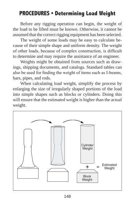
When calculating load weight, simplify the process by enlarging the size of irregularly shaped portions of the load into simple shapes such as blocks or cylinders. Doing this will ensure that the estimated weight is higher than the actual weight.

149
PROCEDURES • Determining Load Weight
Shape: Rectangular Block Material: Steel
Example 1
150
PROCEDURES • Determining Load Weight
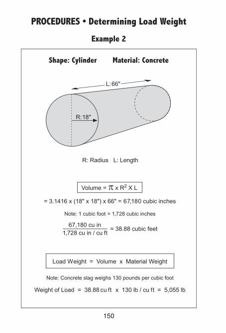
Example 2
Shape: Cylinder Material: Concrete
151
PROCEDURES • Determining Load WeightExample 3
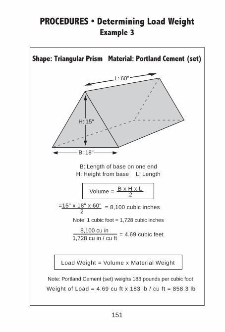
Shape: Triangular Prism Material: Portland Cement (set)
Note: 1 cubic foot = 1,728 cubic inches
L: 60"
H: 15"
B: 18"
B: Length of base on one end
Load Weight = Volume x Material Weight
Weight of Load = 4.69 cu ft x 183 lb / cu ft = 858.3 lb
H: Height from base L: Length
=15" x 18" x 60" = 8,100 cubic inches
8,100 cu in1,728 cu in / cu ft
= 4.69 cubic feet
Note: Portland Cement (set) weighs 183 pounds per cubic foot
Volume = B x H x L2
2

152
PROCEDURES • Determining Load Weight
Aluminum 165 Asbestos 153 Asphalt 81 Brass 534 Brick(Soft) 110 Brick(Common) 125 Brick(Pressed) 140 Bronze 534 Coal 84 Concrete(Slag) 130 Concrete(Reinforced) 150 Copper 556 CrushedRock 95 DieselFuel 52 Earth,Dry(Loose) 75 Earth,Dry(Packed) 95 Earth,Wet 100 Glass 161 Granite 168 Ice 58 Iron 485 Lead 711 Lime:Gypsum(Loose) 64
Limestone(solid) 163 Lumber:Douglas-fir 34 Lumber:Oak 62 Lumber:Pine 45 Lumber:Poplar 30 Lumber:Spruce 28 Lumber:RailroadTies 50 Marble 170 MotorOil 60 Paper 75 Petroleum:Crude 55 Petroleum:Gasoline 45 PortlandCement(Loose) 94 PortlandCement(Set) 183 RiverSand 120 Rubber 95 Sand&Gravel(Wet) 125 Sand&Gravel(Dry) 108 Steel 490 Tar 75 Tin 460 Water 65 Zinc 440
Weights of Materials and Liquids – lb per cubic ft
Weights of Steel and Aluminum Plateslb per square ft
PlateSize (inches) Steel Aluminum
1/8 5 1.75 1/4 10 3.50 1/2 20 7.00 3/4 30 10.50 1 40 14.00
153
PROCEDURES • Center of Gravity
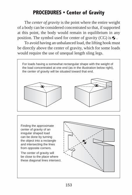
The center of gravity is the point where the entire weight of a body can be considered concentrated so that, if supported at this point, the body would remain in equilibrium in any position. The symbol used for center of gravity (CG) is .
To avoid having an unbalanced load, the lifting hook must be directly above the center of gravity, which for some loads would require the use of unequal length sling legs.
Finding the approximatecenter of gravity of anirregular shaped loadcan be done by turningthe object into a rectangleand intersecting the linesfrom opposite corners.
The center of gravity willbe close to the place wherethese diagonal lines intersect.
For loads having a somewhat rectangular shape with the weight ofthe load concentrated at one end (as in the illustration below right), the center of gravity will be situated toward that end.

154
PROCEDURES • Center of Gravity
When a load is suspended, its center of gravity will hang directly below the hook. Using equal length slings on an ir-regularly shaped load will cause the load to tilt. For the load to hang level, unequal length slings will have to be used.
Rigging the load below the center of gravity can result in the load shifting. In order for loads to remain stable, attach-ment points should be above the center of gravity.
For the load to remain stable,rigging should be attachedabove the center of gravity (left).
Lifting loads riggedbelow the center ofgravity can result inthe load becomingunstable (right).
155
PROCEDURES • Handling Loads
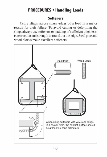
SoftenersUsing slings across sharp edges of a load is a major
reason for their failure. To avoid cutting or deforming the sling, always use softeners or padding of sufficient thickness, construction and strength to round out the edge. Steel pipe and wood blocks make excellent softeners.
When using softeners with wire rope slingsin a choker hitch, the contact surface shouldbe at least six rope diameters.
156
PROCEDURES • Handling Loads
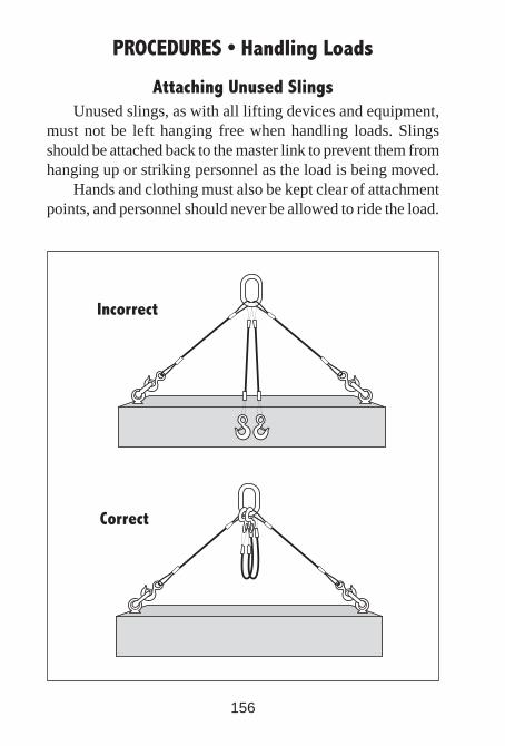
Attaching Unused SlingsUnused slings, as with all lifting devices and equipment,
must not be left hanging free when handling loads. Slings should be attached back to the master link to prevent them from hanging up or striking personnel as the load is being moved.
Hands and clothing must also be kept clear of attachment points, and personnel should never be allowed to ride the load.
157
PROCEDURES • Handling Loads
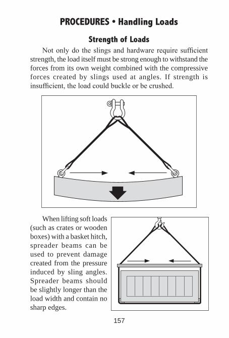
Strength of LoadsNot only do the slings and hardware require sufficient
strength, the load itself must be strong enough to withstand the forces from its own weight combined with the compressive forces created by slings used at angles. If strength is insufficient, the load could buckle or be crushed.
When lifting soft loads (such as crates or wooden boxes) with a basket hitch, spreader beams can be used to prevent damage created from the pressure induced by sling angles. Spreader beams should be slightly longer than the load width and contain no sharp edges.
158
PROCEDURES • Handling Loads
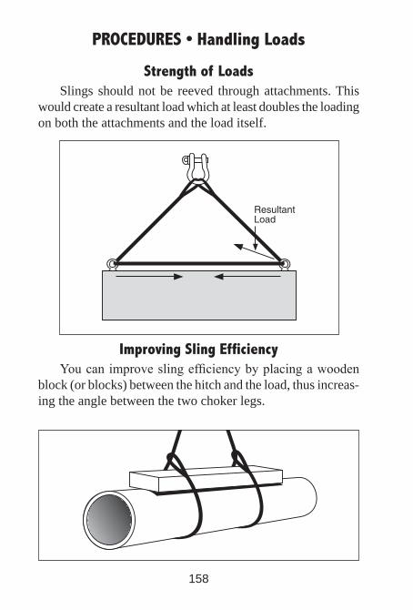
Strength of LoadsSlings should not be reeved through attachments. This
would create a resultant load which at least doubles the loading on both the attachments and the load itself.
Improving Sling EfficiencyYou can improve sling efficiency by placing a wooden
block (or blocks) between the hitch and the load, thus increas-ing the angle between the two choker legs.

159
PROCEDURES • Handling Loads
Turning LoadsTo turn a load, use a double choker with the sling body
passing through the eyes of the sling with the eyes placed in the opposite direction of the turn. To avoid unequal loading of the legs, make sure the center of the sling body is placed over the hook and not the sling eyes.
This method pro-vides good control over the load because its weight is applied against the sling, al-lowing little or no movement between sling and load.
Turning a load with one hook requires the sling to be attached to the side of the load above the center of gravity. To prevent the load from sliding, the load may have to be simultaneously lifted and moved in the direction of the turn.

160
PROCEDURES • Handling Loads
Securing LoadsTo prevent loads from becoming dislodged and possibly
falling, they must be secured before lifting – especially when lifting loose material and objects such as bricks and blocks.
To ensure that loosematerials do not fall,they must be secured.

161
PROCEDURES • Handling Loads
Securing LoadsTo avoid having to detach the lifting device from the load,
it is common for workers to use “homemade” rigging equip-ment. One example is to lift wooden trusses with a homemade hook made from a steel rod (or a conventional hook with the latch removed, taped or wired back).
However, there have been cases where a truss has come out of the hook before being secured in place, resulting in a worker being seriously injured or killed. To avoid such ac-cidents, loads must be well secured and properly balanced in the sling or approved lifting device.
Before being lifted more than a few inches, the load must be well secured and properly balanced in the sling or lifting device.
162
PROCEDURES • Handling Loads
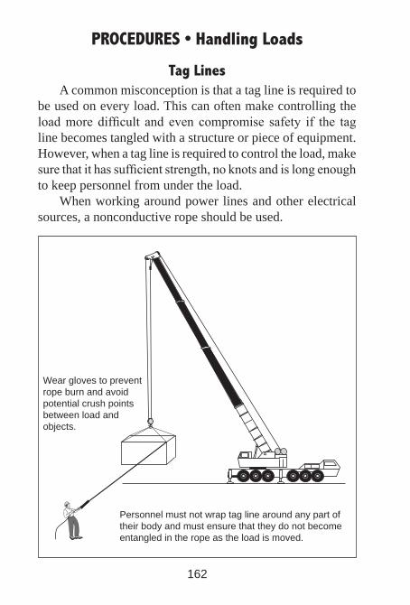
Tag LinesA common misconception is that a tag line is required to
be used on every load. This can often make controlling the load more difficult and even compromise safety if the tag line becomes tangled with a structure or piece of equipment. However, when a tag line is required to control the load, make sure that it has sufficient strength, no knots and is long enough to keep personnel from under the load.
When working around power lines and other electrical sources, a nonconductive rope should be used.
Personnel must not wrap tag line around any part of their body and must ensure that they do not become entangled in the rope as the load is moved.
Wear gloves to prevent rope burn and avoid potential crush points between load and objects.
163
PROCEDURES • Handling Loads
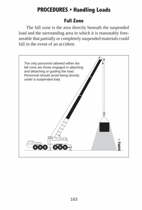
Fall ZoneThe fall zone is the area directly beneath the suspended
load and the surrounding area in which it is reasonably fore-seeable that partially or completely suspended materials could fall in the event of an accident.
The only personnel allowed within the fall zone are those engaged in attaching and detaching or guiding the load. Personnel should avoid being directly under a suspended load.
164
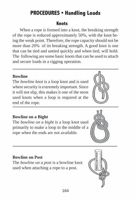
Bowline on a BightThe bowline on a bight is a loop knot used primarily to make a loop in the middle of a rope when the ends are not available.
PROCEDURES • Handling Loads
Bowline on PostThe bowline on a post is a bowline knot used when attaching a rope to a post.
Knots When a rope is formed into a knot, the breaking strength
of the rope is reduced approximately 50%, with the knot be-ing the weak point. Therefore, the rope capacity should not be more than 20% of its breaking strength. A good knot is one that can be tied and untied quickly and when tied, will hold. The following are some basic knots that can be used to attach and secure loads in a rigging operation.
BowlineThe bowline knot is a loop knot and is used where security is extremely important. Since it will not slip, this makes it one of the most used knots when a loop is required at the end of the rope.
165
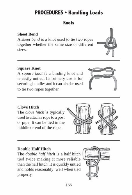
Double Half HitchThe double half hitch is a half hitch tied twice making it more reliable than the half hitch. It is quickly untied and holds reasonably well when tied properly.
PROCEDURES • Handling Loads
Clove HitchThe clove hitch is typically used to attach a rope to a post or pipe. It can be tied in the middle or end of the rope.
Square KnotA square knot is a binding knot and is easily untied. Its primary use is for securing bundles and it can also be used to tie two ropes together.
Sheet BendA sheet bend is a knot used to tie two ropes together whether the same size or different sizes.
Knots
166
PROCEDURES • Handling Loads
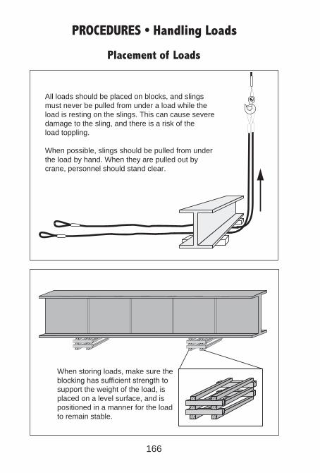
When storing loads, make sure theblocking has sufficient strength tosupport the weight of the load, isplaced on a level surface, and ispositioned in a manner for the loadto remain stable.
Placement of Loads
All loads should be placed on blocks, and slings must never be pulled from under a load while the load is resting on the slings. This can cause severedamage to the sling, and there is a risk of theload toppling.
When possible, slings should be pulled from underthe load by hand. When they are pulled out by crane, personnel should stand clear.
167
PROCEDURES • Communicating with the Operator
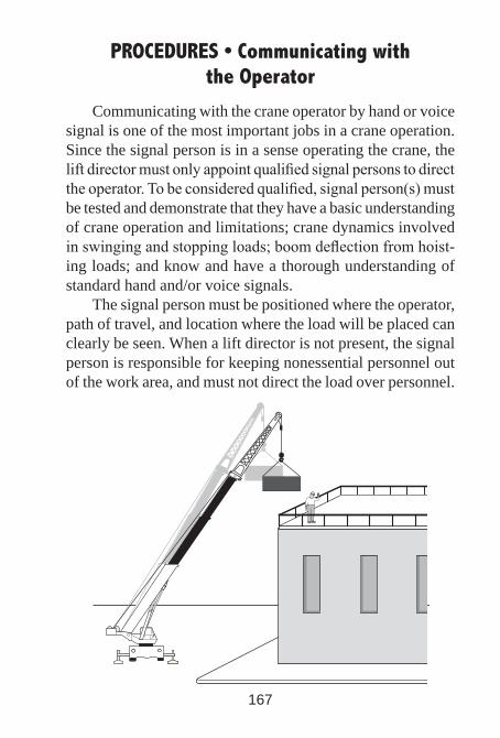
Communicating with the crane operator by hand or voice signal is one of the most important jobs in a crane operation. Since the signal person is in a sense operating the crane, the lift director must only appoint qualified signal persons to direct the operator. To be considered qualified, signal person(s) must be tested and demonstrate that they have a basic understanding of crane operation and limitations; crane dynamics involved in swinging and stopping loads; boom deflection from hoist-ing loads; and know and have a thorough understanding of standard hand and/or voice signals.
The signal person must be positioned where the operator, path of travel, and location where the load will be placed can clearly be seen. When a lift director is not present, the signal person is responsible for keeping nonessential personnel out of the work area, and must not direct the load over personnel.
168
PROCEDURES • Communicating with the Operator
Communication between the signal person and the crane operator must be continuous. If communication is disrupted, crane movements must be stopped until communication is restored and a proper signal is given and understood.
Signals must be discernible or audible and if not under-stood, no response by the operator should be made. Unless voice communication equipment is used, standard hand sig-nals used to direct the operator must be those prescribed in applicable ASME B30 Standards.
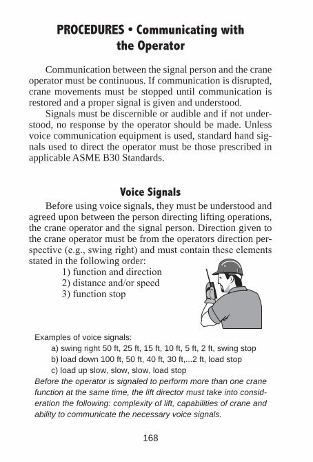
Voice SignalsBefore using voice signals, they must be understood and
agreed upon between the person directing lifting operations, the crane operator and the signal person. Direction given to the crane operator must be from the operators direction per-spective (e.g., swing right) and must contain these elements stated in the following order:
1) function and direction 2) distance and/or speed 3) function stop
Examples of voice signals:a) swing right 50 ft, 25 ft, 15 ft, 10 ft, 5 ft, 2 ft, swing stopb) load down 100 ft, 50 ft, 40 ft, 30 ft,...2 ft, load stopc) load up slow, slow, slow, load stop
Before the operator is signaled to perform more than one crane function at the same time, the lift director must take into consid-eration the following: complexity of lift, capabilities of crane and ability to communicate the necessary voice signals.
169
PROCEDURES • Communicating with the Operator
Special SignalsSpecial signals may be used for operations or crane at-
tachments which are not covered by standard signals. Modi-fications of the standard voice or hand signals must be agreed upon in advance by the person directing lifting operations, the crane operator, and the signal person. These special signals must not conflict with standard signals.
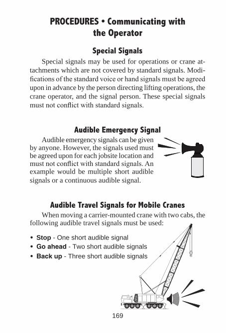
Audible Emergency SignalAudible emergency signals can be given
by anyone. However, the signals used must be agreed upon for each jobsite location and must not conflict with standard signals. An example would be multiple short audible signals or a continuous audible signal.
Audible Travel Signals for Mobile CranesWhen moving a carrier-mounted crane with two cabs, the
following audible travel signals must be used:
• Stop - One short audible signal• Goahead - Two short audible signals• Backup - Three short audible signals
170
PROCEDURES • Communicating with the Operator
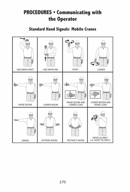
Standard Hand Signals: Mobile Cranes

171
Standard Hand Signals: Mobile Cranes (Continued)
PROCEDURES • Communicating with the Operator
172
PROCEDURES • Communicating with the Operator
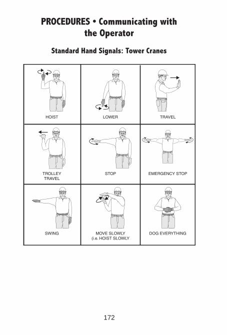
Standard Hand Signals: Tower Cranes
173
PROCEDURES • Communicating with the Operator
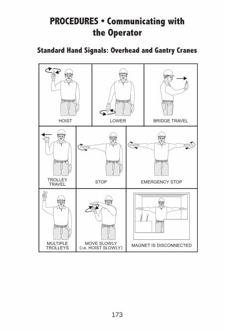
Standard Hand Signals: Overhead and Gantry Cranes
174
PROCEDURES • Hoisting Personnel
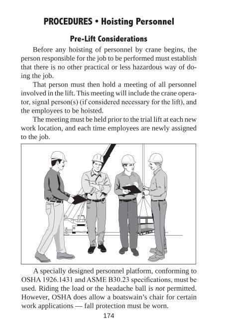
Pre-Lift ConsiderationsBefore any hoisting of personnel by crane begins, the
person responsible for the job to be performed must establish that there is no other practical or less hazardous way of do-ing the job.
That person must then hold a meeting of all personnel involved in the lift. This meeting will include the crane opera-tor, signal person(s) (if considered necessary for the lift), and the employees to be hoisted.
The meeting must be held prior to the trial lift at each new work location, and each time employees are newly assigned to the job.
A specially designed personnel platform, conforming to OSHA 1926.1431 and ASME B30.23 specifications, must be used. Riding the load or the headache ball is not permitted. However, OSHA does allow a boatswain’s chair for certain work applications — fall protection must be worn.
175
PROCEDURES • Hoisting Personnel
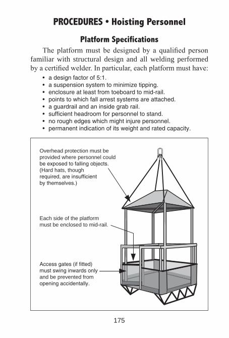
Platform SpecificationsThe platform must be designed by a qualified person
familiar with structural design and all welding performed by a certified welder. In particular, each platform must have: • adesignfactorof5:1. • asuspensionsystemtominimizetipping. • enclosureatleastfromtoeboardtomid-rail. • pointstowhichfallarrestsystemsareattached. • aguardrailandaninsidegrabrail. • sufficientheadroomforpersonneltostand. • noroughedgeswhichmightinjurepersonnel. • permanentindicationofitsweightandratedcapacity.
Accessgates(iffitted)mustswinginwardsonlyand be prevented from openingaccidentally.
Each side of the platformmust be enclosed to mid-rail.
Overhead protection must be provided where personnel couldbeexposedtofallingobjects.(Hard hats, thoughrequired,areinsufficientbythemselves.)

176
PROCEDURES • Hoisting Personnel
Selection of RiggingThe rigging equipment
selected for hoisting person-nel must not be used for any other purpose and should be kept apart from other rigging or clearly identified in some way. It must be capable of handling at least 5 times the maximum intended load and 10 times for rotation resistant wire rope slings.
Eyesinwireropeslingsmustbe fabricated with thimbles.
Wire rope bridles must beattached to a master linkor shackle to ensure evenload distribution.
All hooksmust havelockablelatches.
177
PROCEDURES • Hoisting Personnel
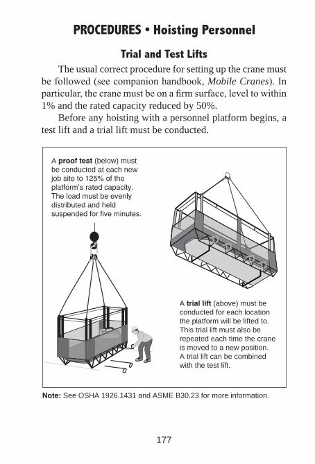
Trial and Test LiftsThe usual correct procedure for setting up the crane must
be followed (see companion handbook, Mobile Cranes). In particular, the crane must be on a firm surface, level to within 1% and the rated capacity reduced by 50%.
Before any hoisting with a personnel platform begins, a test lift and a trial lift must be conducted.
A prooftest (below) mustbe conducted at each newjobsiteto125%oftheplatform’sratedcapacity.Theloadmustbeevenlydistributed and held suspendedforfiveminutes.
A triallift (above) must beconducted for each locationthe platform will be lifted to. This trial lift must also berepeated each time the craneis moved to a new position.A trial lift can be combined with the test lift.
Note:See OSHA 1926.1431 and ASME B30.23 for more information.
178
PROCEDURES • Multi-Crane Lifts
Using more than one crane to lift and place a load com-pounds the risk of the lifting procedure due to the complexity of coordinating the operation. This complexity increases both with the number of cranes lifting the load as well as the maneuvers that must be performed to handle the load. (This is particularly true when utilizing mobile cranes. For example, a simple move-ment such as booming down with a load – which may be safe and proper for a single crane – can cause a catastrophe if not coordinated properly during a multi-crane lift.)
Consequently, detailed plans must be made, preferably by a qualified engineer, for coordinating every step of a multi-crane lifting procedure. The following issues must be addressed:
• Onlyonequalifiedpersonmustdirectalloperationsduring the lift to prevent uncoordinated movements.
• All personnel must understand all phases of the operation in additiontotheirownspecificresponsibilities.
• Plans must include an accurate determination of the share of theloadtobecarriedbyeachcraneaswellasthemethodbywhichthisloaddistributionwillbecontrolledduringlifting.
• Movements with the load should be planned in simple single stepsratherthansimultaneously,andmadeinaslowandcontrolled manner.
• Hoistlinesmustremainvertical.(Thisisabsolutelycriticalwith mobile cranes because of the potential for boom col-lapse from side loading.)
• Areductionof25%innetcapacityforeachcraneshouldbeconsidered, although such a reduction alone should never be viewed as adequate preparation for attempting a tandem lift.
• Allplanningnormallyrequiredforasinglecranelift(suchasverifyingtheadequacyofthesupportingsurface)becomesmore crucial when a multi-crane lift is to be performed.

179
PROCEDURES • Dual Crane Lifts
Determining Loads on Unequally Loaded Cranes
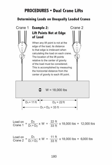
180
PROCEDURES • Dual Crane Lifts
Determining Loads on Unequally Loaded Cranes
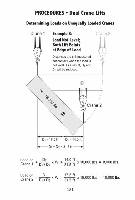
181
PROCEDURES • Dual Crane Lifts
Determining Loads on Unequally Loaded Cranes
1-800-832-2726
19© 2014 Crane Institute of America, LLC. All rights reserved. ILLEGAL TO REPRODUCE without written permission.
1910.184(a) – Scope
This section applies to slings used in conjunction with other material handling equipment for the movement of material by hoisting, in employments covered by this part. The types of slings covered are those made from alloy steel chain, wire rope, metal mesh, natural or synthetic fiber rope (conventional three strand construction), and synthetic web (nylon, polyester, and polypropylene).
1910.184(b) – Definitions
“Angle of loading” is the inclination of a leg or branch of a sling measured from the horizontal or vertical plane; provided that an angle of loading of five degrees or less from the vertical may be considered a vertical angle of loading.
“Basket hitch” is a sling configuration whereby the sling is passed under the load and has both ends, end attachments, eyes or handles on the hook or a single master link.
“Braided wire rope” in a wire rope formed by plaiting component wire ropes.
“Bridle wire rope sling” is a sling composed of multiple wire rope legs with the top ends gathered in a fitting that goes over the lifting hook.
“Cable laid endless sling-mechanical joint” is an endless wire rope sling made from one length of rope wrapped six times around a core formed by hand tucking the ends of the rope inside the six wraps.
“Cable laid rope” is a wire rope composed of six wire ropes wrapped around a fiber or wire rope core.
“Cable laid rope sling-mechanical joint” is a wire rope sling made from a cable laid rope with eyes fabricated by pressing or swaging one ore more metal sleeves over the rope junction.
“Choker hitch” is a sling configuration with one end of the sling passing under the load and through an end attachment handle or eve on the other end of the sling.
“Coating” is an elastomer or other suitable material applied to a sling or to a sling component to impart desirable properties.
“Cross rod” is a wire used to join spirals of metal mesh to form a complete fabric.
“Designated” means selected or assigned by the employer or the employer’s representative as being qualified to perform specific duties.
“Equivalent entity” is a person or organization (including an employer) which, by possession of equipment, technical knowledge and skills, can perform with equal competence the same repairs and tests as the person or organization with which it is equated.
“Fabric (metal mesh)” is the flexible portion of a metal mesh sling consisting of a series of transverse coils and cross rods.
“Female handle (choker)” is a handle with a handle eye and a slot of such dimension as to permit passage of a male handle thereby allowing the use of a metal mesh sling in a choker hitch.
“Handle” is a terminal fitting to which metal mesh fabric is attached.
“Handle eye” is an opening in a handle of a metal mesh sling shaped to accept a hook, shackle or other lifting device.
“Hitch” is a sling configuration whereby the sling is fastened to an object or load, either directly to it or around it.
“Link” is a single ring of a chain.“Male Handle (triangle)” is a handle with a handle
eye.“Master coupling link” is an alloy steel welded
coupling link used as an intermediate link to join alloy steel chain to master links.
“Master link” or “gathering ring” is a forged or welded steel link used to support all members (legs) of an alloy steel chain sling or wire rope sling.
“Mechanical coupling link” is a nonwelded, mechanical closed steel link used to attach master links, hooks, etc., to alloy steel chain.
“Proof load” is the load applied in performance of a proof test.
“Proof test” is a nondestructive tension test performed by the sling manufacturer or an equivalent entity to verify construction and workmanship of a sling.
“Rated capacity” or “working load limit” is the maximum working load permitted by the provisions of this section.
OSHA 1910.184Slings
1-800-832-2726
20© 2014 Crane Institute of America, LLC. All rights reserved. ILLEGAL TO REPRODUCE without written permission.
“Reach” is the effective length of an alloy steel chain sling measured from the top bearing surface of the upper terminal component to the bottom bearing surface of the lower terminal component.
“Selvage edge” is the finished edge of synthetic webbing designed to prevent unraveling.
“Sling” is an assembly which connects the load to the material handling equipment.
“Sling manufacturer” is a person or organization that assembles sling components into their final form for sale to users.
“Spiral” is a single transverse coil that is the basic element from which metal mesh is fabricated.
“Strand laid endless sling-mechanical joint” is a wire rope sling made endless from one length of rope with the ends joined by one or more metallic fittings.
“Strand laid grommet-hand tucked” is an endless wire rope sling made from one length of strand wrapped six times around a core formed by hand tucking the ends of the strand inside the six wraps.
“Strand laid rope” is a wire rope made with stands (usually six or eight) wrapped around fiber core, wire strand core, or independent wire rope core (IWRC).
“Vertical hitch” is a method of supporting a load by a single, vertical part of leg of the sling.
1910.184(c) – Safe operating practices
Whenever any sling is used, the following practices shall be observed:
(1) Slings that are damaged or defective shall not be used.
(2) Slings shall not be shortened with knots or bolts or other makeshift devices.
(3) Sling legs shall not be kinked.(4) Slings shall not be loaded in excess of their
rated capacities.(5) Slings used in a basket hitch shall have the
loads balanced to prevent slippage.(6) Slings shall be securely attached to their loads.(7) Slings shall be padded or protected from the
sharp edges of their loads.(8) Suspended loads shall be kept clear of all
obstructions.(9) All employees shall be kept clear of loads
about to be lifted and of suspended loads.
(10) Hands or fingers shall not be placed between the sling and its load while the sling is being tightened around the load.
(11) Shock loading is prohibited.(12) A sling shall not be pulled from under a load
when the load is resting on the sling.
1910.184(d) – Inspections
Each day before being used, the sling and all fasten-ings and attachments shall be inspected for damage or defects by a competent person designated by the employer. Additional inspections shall be performed during sling use, where service conditions warrant. Damaged or defective slings shall be immediately re-moved from service.
1910.184(e) – Alloy steel chain slings
(1) Sling identification. Alloy steel chain slings shall have permanently affixed durable identification stating size, grade, rated capacity, and reach.
(2) Attachments.(i) Hooks, rings, oblong links, pear shaped
links, welded or mechanical coupling links or other attachments shall have a rated capacity at least equal to that of the alloy steel chain with which they are used or the sling shall not be used in excess of the rated capacity of the weakest component.
(ii) Makeshift links or fasteners formed from bolts or rods, or other such attachments, shall not be used.
(3) Inspections.(i) In addition to the inspection required by
paragraph (d) of this section, a thorough periodic inspection of alloy steel chain slings in use shall be made on a regular basis, to be determined on the basis of (A) frequency of sling use; (B) severity of service conditions; (C) nature of lifts being made; and (D) experience gained on the service life of slings used in similar circumstances. Such inspections shall in no event be at intervals greater than once every 12 months.
1910.184(b) – Definitions (cont’d) 1910.184(c) – Safe operating practices (cont’d)
1-800-832-2726
21© 2014 Crane Institute of America, LLC. All rights reserved. ILLEGAL TO REPRODUCE without written permission.
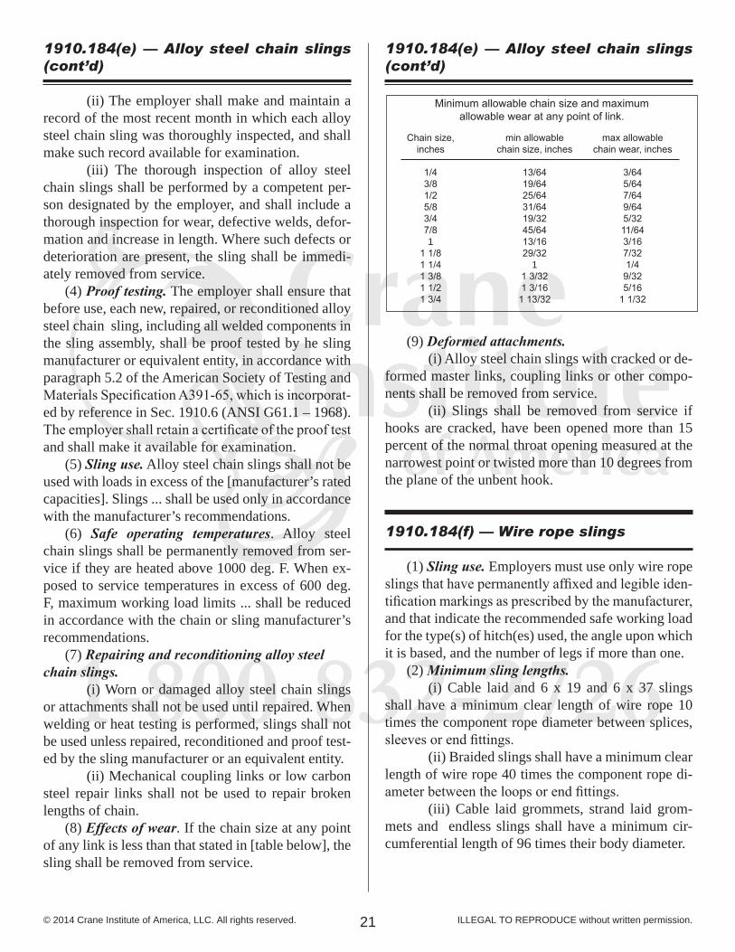
Minimum allowable chain size and maximumallowable wear at any point of link.
Chain size,inches
1/43/81/25/83/47/81
1 1/81 1/41 3/81 1/21 3/4
min allowablechain size, inches
13/6419/6425/6431/6419/3245/6413/1629/32
11 3/321 3/161 13/32
max allowablechain wear, inches
3/645/647/649/645/3211/643/167/321/49/325/16
1 1/32
(ii) The employer shall make and maintain a record of the most recent month in which each alloy steel chain sling was thoroughly inspected, and shall make such record available for examination.
(iii) The thorough inspection of alloy steel chain slings shall be performed by a competent per-son designated by the employer, and shall include a thorough inspection for wear, defective welds, defor-mation and increase in length. Where such defects or deterioration are present, the sling shall be immedi-ately removed from service.
(4) Proof testing. The employer shall ensure that before use, each new, repaired, or reconditioned alloy steel chain sling, including all welded components in the sling assembly, shall be proof tested by he sling manufacturer or equivalent entity, in accordance with paragraph 5.2 of the American Society of Testing and Materials Specification A391-65, which is incorporat-ed by reference in Sec. 1910.6 (ANSI G61.1 – 1968). The employer shall retain a certificate of the proof test and shall make it available for examination.
(5) Sling use. Alloy steel chain slings shall not be used with loads in excess of the [manufacturer’s rated capacities]. Slings ... shall be used only in accordance with the manufacturer’s recommendations.
(6) Safe operating temperatures. Alloy steel chain slings shall be permanently removed from ser-vice if they are heated above 1000 deg. F. When ex-posed to service temperatures in excess of 600 deg. F, maximum working load limits ... shall be reduced in accordance with the chain or sling manufacturer’s recommendations.
(7) Repairing and reconditioning alloy steel chain slings.
(i) Worn or damaged alloy steel chain slings or attachments shall not be used until repaired. When welding or heat testing is performed, slings shall not be used unless repaired, reconditioned and proof test-ed by the sling manufacturer or an equivalent entity.
(ii) Mechanical coupling links or low carbon steel repair links shall not be used to repair broken lengths of chain.
(8) Effects of wear. If the chain size at any point of any link is less than that stated in [table below], the sling shall be removed from service.
(9) Deformed attachments.(i) Alloy steel chain slings with cracked or de-
formed master links, coupling links or other compo-nents shall be removed from service.
(ii) Slings shall be removed from service if hooks are cracked, have been opened more than 15 percent of the normal throat opening measured at the narrowest point or twisted more than 10 degrees from the plane of the unbent hook.
1910.184(f) — Wire rope slings (1) Sling use. Employers must use only wire rope
slings that have permanently affixed and legible iden-tification markings as prescribed by the manufacturer, and that indicate the recommended safe working load for the type(s) of hitch(es) used, the angle upon which it is based, and the number of legs if more than one.
(2) Minimum sling lengths.(i) Cable laid and 6 x 19 and 6 x 37 slings
shall have a minimum clear length of wire rope 10 times the component rope diameter between splices, sleeves or end fittings.
(ii) Braided slings shall have a minimum clear length of wire rope 40 times the component rope di-ameter between the loops or end fittings.
(iii) Cable laid grommets, strand laid grom-mets and endless slings shall have a minimum cir-cumferential length of 96 times their body diameter.
1910.184(e) — Alloy steel chain slings (cont’d)
1910.184(e) — Alloy steel chain slings (cont’d)
1-800-832-2726
22© 2014 Crane Institute of America, LLC. All rights reserved. ILLEGAL TO REPRODUCE without written permission.
(3) Safe operating temperatures. Fiber core wire rope slings of all grades shall be permanently removed from service if they are exposed to temperatures in excess of 200 deg. F. When nonfiber core wire rope slings of any grade are used at temperatures above 400 deg. F or below minus 60 deg. F, recommenda-tions of the sling manufacturer regarding use at that temperature shall be followed.
(4) End attachments.(i) Welding of end attachments, except covers
to thimbles, shall be performed prior to the assembly of the sling.
(ii) All welded end attachments shall not be used unless proof tested by the manufacturer or equivalent entity at twice their rated capacity prior to initial use. The employer shall retain a certificate of the proof test, and make it available for examination.
(5) Removal from service. Wire rope slings shall be immediately removed from service if any of the following conditions are present:
(i) Ten randomly distributed broken wires in one rope lay, or five broken wires in one strand in one rope lay.
(ii) Wear or scraping of one-third the original diameter of outside individual wires.
(iii) Kinking, crushing, bird caging or any other damage resulting in distortion of the wire rope structure.
(iv) Evidence of heat damage.(v) End attachments that are cracked, de-
formed or worn.(vi) Hooks that have been opened more than
15 percent of the normal throat opening measured at the narrowest point or twisted more than 10 degrees from the plane of the unbent hook.
(vii) Corrosion of the rope or end attachments.
1910.184(g) — Metal mesh slings
(1) Sling marking. Each metal mesh sling shall have permanently affixed to it a durable marking that states the rated capacity for vertical basket hitch and choker hitch loadings.
(2) Handles. Handles shall have a rated capacity at least equal to the metal fabric and exhibit no defor-mation after proof testing.
(3) Attachments of handles to fabric. The fabric and handles shall be joined so that:
(i) The rated capacity of the sling is not reduced.(ii) The load is evenly distributed across the
width of the fabric.(iii) Sharp edges will not damage the fabric.
(4) Sling coatings. Coatings which diminish the rated capacity of a sling shall not be applied.
(5) Sling testing. All new and repaired metal mesh slings, including handles, shall not be used unless proof tested by the manufacturer or equivalent entity at a minimum of 1 1/2 times their rated capacity. Elastomer impregnated slings shall be proof tested before coating.
(6) Proper use of metal mesh slings. Metal mesh slings shall not be used to lift loads in excess of their rated capacities as prescribed [by the manufacturer]. Slings not included in this table shall be used only in accordance with the manufacturer’s recommendations.
(7) Safe operating temperatures. Metal mesh slings which are not impregnated with elastomers may be used in a temperature range from minus 20 deg. F to plus 550 deg. F without decreasing the working load limit. Metal mesh slings impregnated with polyvinyl chloride or neoprene may be used only in a tempera-ture range from zero degrees to plus 200 deg. F. For op-erations outside these temperature ranges or for metal mesh slings impregnated with other materials, the sling manufacturer’s recommendations shall be followed.
(8) Repairs.(i) Metal mesh slings which are repaired shall
not be used unless repaired by a metal mesh sling manufacturer or an equivalent entity.
(ii) Once repaired, each sling shall be perma-nently marked or tagged, or a written record main-tained, to indicate the date and nature of the repairs and the person or organization that performed the re-pairs. Records of repairs shall be made available for examination.
(9) Removal from service. Metal mesh slings shall be immediately removed from service if any of the following conditions are present:
(i) A broken weld or broken brazed joint along the sling edge.
(ii) Reduction in wire diameter of 25 percent due to abrasion or 15 percent due to corrosion.
(iii) Lack of flexibility due to distortion of the fabric.
(iv) Distortion of the female handle so that the depth of the slot is increased more than 10 percent.
1910.184(f) — Wire rope slings (cont’d) 1910.184(g) — Metal mesh slings (cont’d)
1-800-832-2726
23© 2014 Crane Institute of America, LLC. All rights reserved. ILLEGAL TO REPRODUCE without written permission.
(v) Distortion of either handle so that the width of the eye is decreased more than 10 per cent.
(vi) A 15 percent reduction of the original cross sectional area of metal at any point around the handle eye.
(vii) Distortion of either handle out of its plane.
1910.184(h) — Natural and synthetic fi-ber rope slings
(1) Sling use.(i) Fiber rope slings made from conventional
three strand construction fiber rope shall not be used with loads in excess of the [manufacturer’s rated capacities].
(ii) Fiber rope slings shall have a diameter of curvature meeting at least the minimums specified in Figures N-184-4 and N-185-5 [not shown; see “Con-tact Surface Requirements for Slings” at right].
(iii) Slings ... shall be used only in accordance with the manufacturer’s recommendations.
(2) Safe operating temperatures. Natural and synthetic fiber rope slings, except for wet frozen slings, may be used in a temperature range from mi-nus 20 deg. F to plus 180 deg. F without decreasing the working load limit. For operations outside this temperature range and for wet frozen slings, the sling manufacturer’s recommendations shall be followed.
(3) Splicing. Spliced fiber rope slings shall not be used unless they have been spliced in accordance with the following minimum requirements and in ac-cordance with any additional recommendations of the manufacturer:
(i) In manila rope, eye splices shall consist of at least three full tucks, and short splices shall con-sist of at least six full tucks, three on each side of the splice center line.
(ii) In synthetic fiber rope, eye splices shall consist of at least four full tucks, and short splices shall consist of at least eight full tucks, four on each side of the center line.
1910.184(g) — Metal mesh slings (cont’d)
(iii) Strand end tails shall not be trimmed flush with the surface of the rope immediately adjacent to the full tucks. This applies to all types of fiber rope and both eye and short splices. For fiber rope under one inch in diameter, the tail shall project at least six rope diameters beyond the last full tuck. For fiber rope one inch in diameter and larger, the tail shall project at least six inches beyond the last full tuck. Where a projecting tail interferes with the use of the sling, the tail shall be tapered and spliced into the body of the rope using at least two additional tucks (which will require a tail length of approximately six rope diam-eters beyond the last full tuck).
(iv) Fiber rope slings shall have a minimum clear length of rope between eye splices equal to 10 times the rope diameter.
(v) Knots shall not be used in lieu of splices.(vi) Clamps not designed specifically for fiber
ropes shall not be used for splicing.(vii) For all eye splices, the eye shall be of
such size to provide an included angle of not greater than 60 degrees at the splice when the eye is placed over the load or support.
(4) End attachments. Fiber rope slings shall not be used if end attachments in contact with the rope have sharp edges or projections.
(5) Removal from service. Natural and synthetic fiber rope slings shall be immediately removed from service if any of the following conditions are present:
(i) Abnormal wear.(ii) Powdered fiber between strands.(iii) Broken or cut fibers.(iv) Variations in the size or roundness of
strands.(v) Discoloration or rotting.(vi) Distortion of hardware in the sling.
(6) Repairs. Only fiber rope slings made from new rope shall be used. Use of repaired or reconditioned fiber rope slings is prohibited.
1910.184(h) — Natural and synthetic fi-ber rope slings (cont’d)
1-800-832-2726
24© 2014 Crane Institute of America, LLC. All rights reserved. ILLEGAL TO REPRODUCE without written permission.
1910.184(i) — Synthetic web slings
(1) Sling identification. Each sling shall be marked or coded to show the rated capacities for each type of hitch and type of synthetic web material.
(2) Webbing. Synthetic webbing shall be of uni-form thickness and width and selvage edges shall not be split from the webbing’s width.
(3) Fittings. Fittings shall be:(i) Of a minimum breaking strength equal to
that of the sling; and (ii) Free of all sharp edges that could in any
way damage the webbing.(4) Attachment of end fittings to webbing and
formation of eyes. Stitching shall be the only method used to attach end fittings to webbing and to form eyes. The thread shall be in an even pattern and con-tain a sufficient number of stitches to develop the full breaking strength of the sling.
(5) Sling use. Synthetic web slings ... shall not be used with loads in excess of the [manufacturer’s rated capacities]. Slings ... shall be used only in accordance with the manufacturer’s recommendations.
(6) Environmental conditions. When synthetic web slings are used, the following precautions shall be taken:
(i) Nylon web slings shall not be used where fumes, vapors, sprays, mists or liquids of acids or phenolics are present.
(ii) Polyester and polypropylene web slings shall not be used where fumes, vapors, sprays, mists or liquids of caustics are present.
(iii) Web slings with aluminum fittings shall not be used where fumes, vapors, sprays, mists or liq-uids of caustics are present.
(7) Safe operating temperatures. Synthetic web slings of polyester and nylon shall not be used at tem-peratures in excess of 180 deg. F. Polypropylene web slings shall not be used at temperatures in excess of 200 deg. F.
(8) Repairs.(i) Synthetic web slings which are repaired
shall not be used unless repaired by a sling manufac-turer or an equivalent entity.
(ii) Each repaired sling shall be proof tested by the manufacturer or equivalent entity to twice the rated capacity prior to its return to service. The em-ployer shall retain a certificate of the proof test and make it available for examination.
1910.184(i) — Synthethic web slings (cont’d)
(iii) Slings, including webbing and fittings, which have been repaired in a temporary manner shall not be used.
(9) Removal from service. Synthetic web slings shall be immediately removed from service if any of the following conditions are present:
(i) Acid or caustic burns;(ii) Melting or charring of any part of the sling
surface;(iii) Snags, punctures, tears or cuts;(iv) Broken or worn stitches; or(v) Distortion of fittings.

1-800-832-2726
25© 2014 Crane Institute of America, LLC. All rights reserved. ILLEGAL TO REPRODUCE without written permission.
OSHA CFR 1926.251Rigging Equipment
for Material Handling
1926.251(a) — General
(1) Rigging equipment for material handling shall be inspected prior to use on each shift and as nec-essary during its use to ensure that it is safe. Defective rigging equipment shall be removed from service. (2) Rigging equipment shall not be loaded in ex-cess of its recommended safe working load, as pre-scribed in Tables H-1 through H-20 in this subpart, following 1926.252(e) for the specific equipment. (3) Rigging equipment, when not in use, shall be removed from the immediate work area so as not to present a hazard to employees. (4) Special custom design grabs, hooks, clamps, or other lifting accessories, for such units as modular panels, prefabricated structures and similar materials, shall be marked to indicate the safe working loads and shall be proof-tested prior to use to 125 percent of their rated load. (5) “Scope.” This section applies to slings used in conjunction with other material handling equipment for the movement of material by hoisting, in employ-ments covered by this part. The types of slings cov-ered are those made from alloy steel chain, wire rope, metal mesh, natural or synthetic fiber rope (conven-tional three strand construction), and synthetic web (nylon, polyester, and polypropylene). (6) “Inspections.” Each day before being used, the sling and all fastenings and attachments shall be inspected for damage or defects by a competent per-son designated by the employer. Additional inspec-tions shall be performed during sling use, where ser-vice conditions warrant. Damaged or defective slings shall be immediately removed from service.
1926.251(b) — Alloy steel chains (1) Welded alloy steel chain slings shall have per-manently affixed durable identification stating size, grade, rated capacity, and sling manufacturer. (2) Hooks, rings, oblong links, pear-shaped links, welded or mechanical coupling links, or other attach-ments, when used with alloy steel chains, shall have a rated capacity at least equal to that of the chain. (3) Job or shop hooks and links, or makeshift fas-teners, formed from bolts, rods, etc., or other such at-tachments, shall not be used. (4) Rated capacity (working load limit) for alloy steel chain slings shall conform to the values shown in Table H-1. (5) Whenever wear at any point of any chain link exceeds that shown in Table H-2, the assembly shall be removed from service. (6) “Inspections.” (i) In addition to the inspection required by other paragraphs of this section, a thorough periodic inspection of alloy steel chain slings in use shall be made on a regular basis, to be determined on the basis of (A) frequency of sling use; (B) severity of service conditions; (C) nature of lifts being made; and (D) experience gained on the service life of slings used in similar circumstances. Such inspections shall in no event be at inter-vals greater than once every 12 months. (ii) The employer shall make and maintain a record of the most recent month in which each alloy steel chain sling was thoroughly inspected, and shall make such record available for examination.
1-800-832-2726
26© 2014 Crane Institute of America, LLC. All rights reserved. ILLEGAL TO REPRODUCE without written permission.
1926.251(c) — Wire rope
(1) Tables H-3 through H-14 shall be used to de-termine the safe working loads of various sizes and classifications of improved plow steel wire rope and wire rope slings with various types of terminals. For sizes, classifications, and grades not included in these tables, the safe working load recommended by the manufacturer for specific, identifiable products shall be followed, provided that a safety factor of not less than 5 is maintained. (2) Protruding ends of strands in splices on slings and bridles shall be covered or blunted. (3) Wire rope shall not be secured by knots, ex-cept on haul back lines on scrapers. (4) The following limitations shall apply to the use of wire rope: (i) An eye splice made in any wire rope shall have not less than three full tucks. However, this re-quirement shall not operate to preclude the use of another form of splice or connection which can be shown to be as efficient and which is not otherwise prohibited. (ii) Except for eye splices in the ends of wires and for endless rope slings, each wire rope used in hoisting or lowering, or in pulling loads, shall consist of one continuous piece without knot or splice. (iii) Eyes in wire rope bridles, slings, or bull wires shall not be formed by wire rope clips or knots. (iv) Wire rope shall not be used if, in any length of eight diameters, the total number of visible broken wires exceeds 10 percent of the total number of wires, or if the rope shows other signs of excessive wear, corrosion, or defect. (5) When U-bolt wire rope clips are used to form eyes, Table H-20 shall be used to determine the num-ber and spacing of clips. (i) When used for eye splices, the U-bolt shall be applied so that the “U” section is in contact with the dead end of the rope. (6) Slings shall not be shortened with knots or bolts or other makeshift devices. (7) Sling legs shall not be kinked. (8) Slings used in a basket hitch shall have the loads balanced to prevent slippage. (9) Slings shall be padded or protected from the sharp edges of their loads.
(10) Hands or fingers shall not be placed between the sling and its load while the sling is being tightened around the load. (11) Shock loading is prohibited. (12) A sling shall not be pulled from under a load when the load is resting on the sling. (13) “Minimum sling lengths.” (i) Cable laid and 6 x 19 and 6 x 37 slings shall have minimum clear length of wire rope 10 times the component rope diameter between splices, sleeves or end fittings. (ii) Braided slings shall have a minimum clear length of wire rope 40 times the component rope di-ameter between the loops or end fittings. (iii) Cable laid grommets, strand laid grom-mets and endless slings shall have a minimum cir-cumferential length of 96 times their body diameter. (14) “Safe operating temperatures.” Fiber core wire rope slings of all grades shall be permanently removed from service if they are exposed to tempera-tures in excess of 200 deg. F (93.33 deg. C). When nonfiber core wire rope slings of any grade are used at temperatures above 400 deg. F (204.44 deg. C) or below minus 60 deg. F (15.55 deg. C), recommenda-tions of the sling manufacturer regarding use at that temperature shall be followed. (15) “End attachments.” (i) Welding of end attachments, except covers to thimbles, shall be performed prior to the assembly of the sling. (ii) All welded end attachments shall not be used unless proof tested by the manufacturer or equivalent entity at twice their rated capacity prior to initial use. The employer shall retain a certificate of proof test, and make it available for examination.
1926.251(d) — Natural rope, and synthetic fiber
(1) General. When using natural or synthetic fiber rope slings, Tables H-15, 16, 17, and 18 shall apply. (2) All splices in rope slings provided by the em-ployer shall be made in accordance with fiber rope manufacturers recommendations.
1926.251(c) — Wire rope (cont’d)
1-800-832-2726
27© 2014 Crane Institute of America, LLC. All rights reserved. ILLEGAL TO REPRODUCE without written permission.
(i) In manila rope, eye splices shall contain at least three full tucks, and short splices shall contain at least six full tucks (three on each side of the center line of the splice). (ii) In layed synthetic fiber rope, eye splices shall contain at least four full tucks, and short splices shall contain at least eight full tucks (four on each side of the center line of the splice). (iii) Strand end tails shall not be trimmed short (flush with the surface of the rope) immediately adja-cent to the full tucks. This precaution applies to both eye and short splices and all types of fiber rope. For fi-ber ropes under 1-inch diameter, the tails shall project at least six rope diameters beyond the last full tuck. For fiber ropes 1-inch diameter and larger, the tails shall project at least 6 inches beyond the last full tuck. In applications where the projecting tails may be ob-jectionable, the tails shall be tapered and spliced into the body of the rope using at least two additional tucks (which will require a tail length of approximately six rope diameters beyond the last full tuck). (iv) For all eye splices, the eye shall be suf-ficiently large to provide an included angle of not greater than 60 deg. at the splice when the eye is placed over the load or support. (v) Knots shall not be used in lieu of splices. (3) “Safe operating temperatures.” Natural and synthetic fiber rope slings, except for wet frozen slings, may be used in a temperature range from mi-nus 20 deg. F (-28.88 deg. C) to plus 180 deg. F (82.2 deg. C) without decreasing the working load limit. For operations outside this temperature range and for wet frozen slings, the sling manufacturer’s recom-mendations shall be followed. (4) “Splicing.” Spliced fiber rope slings shall not be used unless they have been spliced in accordance with the following minimum requirements and in ac-cordance with any additional recommendations of the manufacturer: (i) In manila rope, eye splices shall consist of at least three full tucks, and short splices shall con-sist of at least six full tucks, three on each side of the splice center line.
1926.251(d) — Natural Rope, and synthetic fiber (cont’d)
(ii) In synthetic fiber rope, eye splices shall consist of at least four full tucks, and short splices shall consist of at least eight full tucks, four on each side of the center line. (iii) Strand end tails shall not be trimmed flush with the surface of the rope immediately adjacent to the full tucks. This applies to all types of fiber rope and both eye and short splices. For fiber rope under 1 inch (2.54 cm) in diameter, the tail shall project at least six rope diameters beyond the last full tuck. For fiber rope 1 inch (2.54 cm) in diameter and larger, the tail shall project at least 6 inches (15.24 cm) beyond the last full tuck. Where a projecting tail interferes with the use of the sling, the tail shall be tapered and spliced into the body of the rope using at lest two addi-tional tucks (which will require a tail length of approx-imately six rope diameters beyond the last full tuck). (iv) Fiber rope slings shall have a minimum clear length of rope between eye splices equal to 10 times the rope diameter. (v) Knots shall not be used in lieu of splices. (vi) Clamps not designed specifically for fiber ropes shall not be used for splicing. (vii) For all eye splices, the eye shall be of such size to provide an included angle of not greater than 60 degrees at the splice when the eye is placed over the load or support. (5) “End attachments.” Fiber rope slings shall not be used if end attachments in contact with the rope have sharp edges or projections. (6) “Removal from service.” Natural and syn-thetic fiber rope slings shall be immediately removed from service if any of the following conditions are present: (i) Abnormal wear. (ii) Powdered fiber between strands. (iii) Broken or cut fibers. (iv) Variations in the size or roundness of strands. (v) Discoloration or rotting. (vi) Distortion of hardware in the sling.
1926.251(d) — Natural Rope, and synthetic fiber (cont’d)
1-800-832-2726
28© 2014 Crane Institute of America, LLC. All rights reserved. ILLEGAL TO REPRODUCE without written permission.
16
Table H-19Safe Working Loads for Shackles
Material Size Pin Safe(inches) Diameter Working
(inches) Load
1/2 5/8 1.45/8 3/4 2.23/4 7/8 3.27/8 1 4.3
1 1 1/8 5.61 1/8 1 1/4 6.71 1/4 1 3/8 8.21 3/8 1 1/2 10.01 1/2 1 5/8 11.91 3/4 2 16.22 2 1/4 21.2
Table H-20Number and Spacing of U-Bolt Wire Rope Clips
Improved Number of ClipsPlow Steel MinimumRope Diameter Drop Other Spacing(inches) Forged Material (inches)
1/2 3 4 35/8 3 4 3 3/43/4 4 5 4 1/27/8 4 5 5 1/4
1 5 6 61 1/8 6 6 6 3/41 1/4 6 7 7 1/21 3/8 7 7 8 1/41 1/2 7 8 9
[44 FR 8577, Feb. 9, 1979; 44 FR 20940, Apr. 6, 1979, as amendedat 58 FR 35173, June 30, 1993]
©2007 CIA, Inc. Illegal to reproduce without written permission.
1926.251(e) — Synthetic webbing (nylon, polyester, and polypropylene)
(1) The employer shall have each synthetic web sling marked or coded to show: (i) Name or trademark of manufacturer. (ii) Rated capacities for the type of hitch. (iii) Type of material. (2) Rated capacity shall not be exceeded. (3) “Webbing.” Synthetic webbing shall be of uniform thickness and width and selvage edges shall not be split from the webbing’s width. (4) “Fittings.” Fittings shall be: (i) Of a minimum breaking strength equal to that of the sling; and (ii) Free of all sharp edges that could in any way damage the webbing. (5) “Attachment of end fittings to webbing and formation of eyes.” Stitching shall be the only meth-od used to attach end fittings to webbing and to form eyes. The thread shall be in an even pattern and con-tain a sufficient number of stitches to develop the full breaking strength of the sling. (6) “Environmental conditions.” When synthetic web slings are used, the following precautions shall be taken: (i) Nylon web slings shall not be used where fumes, vapors, sprays, mists or liquids of acids or phenolics are present. (ii) Polyester and polypropylene web slings shall not be used where fumes, vapors, sprays, mists or liquids of caustics are present. (iii) Web slings with aluminum fittings shall not be used where fumes, vapors, sprays, mists or liq-uids of caustics are present. (7) “Safe operating temperatures.” Synthetic web slings of polyester and nylon shall not be used at temperatures in excess of 180 deg. F (82.2 deg. C). Polypropylene web slings shall not be used at tem-peratures in excess of 200 deg. F (93.33 deg. C). (8) “Removal from service.” Synthetic web slings shall be immediately removed from service if any of the following conditions are present: (i) Acid or caustic burns; (ii) Melting or charring of any part of the sling surface; (iii) Snags, punctures, tears or cuts; (iv) Broken or worn stitches; or (v) Distortion of fittings.
1926.251(f) — Shackles and hooks
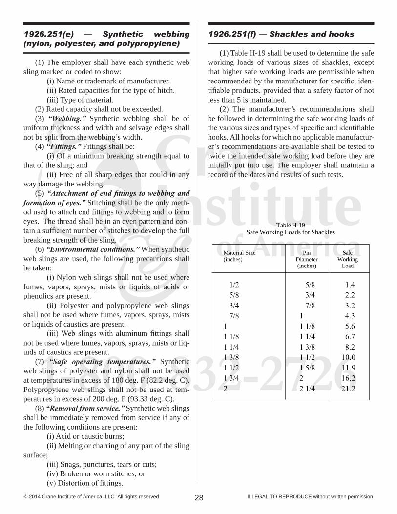
(1) Table H-19 shall be used to determine the safe working loads of various sizes of shackles, except that higher safe working loads are permissible when recommended by the manufacturer for specific, iden-tifiable products, provided that a safety factor of not less than 5 is maintained. (2) The manufacturer’s recommendations shall be followed in determining the safe working loads of the various sizes and types of specific and identifiable hooks. All hooks for which no applicable manufactur-er’s recommendations are available shall be tested to twice the intended safe working load before they are initially put into use. The employer shall maintain a record of the dates and results of such tests.
1-800-832-2726
29© 2014 Crane Institute of America, LLC. All rights reserved. ILLEGAL TO REPRODUCE without written permission.
1926.753(a)
All the provisions of §1926.550 apply to hoisting and rigging with the exception of §1926.550 (g)(2).
1926.753(b)
In addition, paragraphs (c) through (e) of this section apply regarding the hazards associated with hoisting and rigging.
1926.753(c) — General
(1) Pre-shift visual inspection of cranes.(i) Cranes being used in steel erection activi-
ties shall be visually inspected prior to each shift by a competent person; the inspection shall include ob-servation for deficiencies during operation. At a mini-mum this inspection shall include the following:
(A) All control mechanisms for maladjustments;
(B) Control and drive mechanism for ex-cessive wear of components and contamination by lu-bricants, water or other foreign matter.
(C) Safety devices, including but not lim-ited to boom angle indicators, boom stops, boom kick out devices, anti-two block devices, and load moment indicators where required;
(D) Air, hydraulic, and other pressurized lines for deterioration or leakage, particularly those which flex in normal operation;
(E) Hooks and latches for deformation, chemical damage, cracks, or wear;
(F) Wire rope reeving for compliance with hoisting equipment manufacturer’s specifications;
(G) Electrical apparatus for malfunction-ing, signs of excessive deterioration, dirt, or moisture accumulation;
(H) Hydraulic system for proper fluid level;
(I) Tires for proper inflation and condition;
(J) Ground conditions around the hoisting equipment for proper support, including ground set-tling under and around outriggers, ground water ac-cumulation, or similar conditions;
(K) The hoisting equipment for level posi-tion; and
(L) The hoisting equipment for level posi-tion after each move and setup.
(ii) If any deficiency is identified, an immedi-ate determination shall be made by the competent per-son as to whether the deficiency constitutes a hazard.
(iii) If the deficiency is determined to consti-tute a hazard, the hoisting equipment shall be removed from service until the deficiency has been corrected.
(iv) The operator shall be responsible for those operations under the operator’s direct control. When-ever there is any doubt as to safety, the operator shall have the authority to stop and refuse to handle loads until safety has been assured.
(2) A qualified rigger (a rigger who is also a quali-fied person) shall inspect the rigging prior to each shift in accordance with §1926.251.
(3) The headache ball, hook or load shall not be used to transport personnel except as provided in paragraph (c)(4) of this section.
(4) Cranes or derricks may be used to hoist em-ployees on a personnel platform when work under this subpart is being conducted, provided that all provi-sions of §1926.550 (except for §1926.550 (g)(2)) are met.
(5) Safety latches on hooks shall not be deactivat-ed or made inoperable except:
(i) When a qualified rigger has determined that the hoisting and placing of purlins and single joists can be performed more safely by doing so; or
(ii) When equivalent protection is provided in a site-specific erection plan.
OSHA 1926.753Hoisting and Rigging
(Steel Erection)
1-800-832-2726
30© 2014 Crane Institute of America, LLC. All rights reserved. ILLEGAL TO REPRODUCE without written permission.
1926.753(d) — Working under loads
(1) Routes for suspended loads shall be pre-planned to ensure that no employee is required to work directly below a suspended load except for:
(i) Employees engaged in the initial connection of the steel; or
(ii) Employees necessary for the hooking or unhooking of the load.
(2) When working under suspended loads, the following criteria shall be met:
(i) Materials being hoisted shall be rigged to prevent unintentional displacement;
(ii) Hooks with self-closing safety latches or their equivalent shall be used to prevent components from slipping out of the hook; and
(iii) All loads shall be rigged by a qualified rigger.
1926.753(e) — Multiple lift rigging pro-cedure
(1) A multiple lift shall only be performed if the following criteria are met:
(i) A multiple lift rigging assembly is used;(ii) A maximum of five members are hoisted
per lift;(iii) Only beams and similar structural
members are lifted; and(iv) All employees engaged in the multiple lift
have been trained in these procedures in accordance with §1926.761(c)(1).
(v) No crane is permitted to be used for a multiple lift where such use is contrary to the manufacturer’s specifications and limitations.
(2) Components of the multiple lift rigging assembly shall be specifically designed and assembled with a maximum capacity for total assembly and for each individual attachment point. This capacity, certified by the manufacturer or a qualified rigger, shall be based on the manufacturer’s specifications with a 5 to 1 safety factor for all components.
(3) The total load shall not exceed:(i) The rated capacity of the hoisting equipment
specified in the hoisting equipment load charts;(ii) The rigging capacity specified in the
rigging rating chart.(4) The multiple lift rigging assembly shall be
rigged with members:(i) Attached at their center of gravity and
maintained reasonably level;(ii) Rigged from top down; and(iii) Rigged at least 7 feet (2.1 m) apart.
(5) The members on the multiple lift rigging assembly shall be set from the bottom up.
(6) Controlled load lowering shall be used whenever the load is over the connectors.
____________________________________________[59 FR 40729, Aug. 9, 1994; 60 FR 5131, Jan. 26, 1995; 60 FR 39254, Aug. 2, 1995; 66 FR 5267, Jan. 18, 2001]
1-800-832-2726
31© 2014 Crane Institute of America, LLC. All rights reserved. ILLEGAL TO REPRODUCE without written permission.
1926.1400 — Scope
(a) This standard applies to power-operated equip-ment, when used in construction, that can hoist, lower and horizontally move a suspended load. Such equip-ment includes, but is not limited to: articulating cranes (such as knuckle-boom cranes); crawler cranes; float-ing cranes; cranes on barges; locomotive cranes; mo-bile cranes (such as wheelmounted, rough-terrain, all-terrain, commercial truck-mounted, and boom truck cranes); multi-purpose machines when configured to hoist and lower (by means of a winch or hook) and horizontally move a suspended load; industrial cranes (such as carry-deck cranes); dedicated pile drivers; service/ mechanic trucks with a hoisting device; a crane on a monorail; tower cranes (such as a fixed jib, i.e., “hammerhead boom”), luffing boom and self-erecting); pedestal cranes; portal cranes; overhead and gantry cranes; straddle cranes; sideboom cranes; derricks; and variations of such equipment. However, items listed in paragraph (c) of this section are ex-cluded from the scope of this standard. (b) Attachments. This standard applies to equip-ment included in paragraph (a) of this section when used with attachments. Such attachments, whether crane-attached or suspended include, but are not lim-ited to: hooks, magnets, grapples, clamshell buckets, orange peel buckets, concrete buckets, drag lines, personnel platforms, augers or drills and pile driving equipment. (c) Exclusions. This subpart does not cover: (1) Machinery included in paragraph (a) of this section while it has been converted or adapted for a non-hoisting/lifting use. Such conversions/adapta-tions include, but are not limited to, power shovels, excavators and concrete pumps. (2) Power shovels, excavators, wheel load-ers, backhoes, loader backhoes, track loaders. This machinery is also excluded when used with chains, slings or other rigging to lift suspended loads.
(3) Automotive wreckers and tow trucks when used to clear wrecks and haul vehicles. (4) Digger derricks when used for augering holes for poles carrying electric and telecommunica-tion lines, placing and removing the poles, and for handling associated materials to be installed on or re-moved from the poles. Digger derricks used in work subject to 29 CFR part 1926, subpart V, must comply with 29 CFR 1910.269. Digger derricks used in con-struction work for telecommunication service (as de-fined at 29 CFR 1910.268(s)(40)) must comply with 29 CFR 1910.268. (5) Machinery originally designed as vehicle-mounted aerial devices (for lifting personnel) and self-propelled elevating work platforms. (6) Telescopic/hydraulic gantry systems. (7) Stacker cranes. (8) Powered industrial trucks (forklifts), ex-cept when configured to hoist and lower (by means of a winch or hook) and horizontally move a suspended load. (9) Mechanic’s truck with a hoisting device when used in activities related to equipment mainte-nance and repair. (10) Machinery that hoists by using a come-a-long or chainfall. (11) Dedicated drilling rigs. (12) Gin poles when used for the erection of communication towers. (13) Tree trimming and tree removal work. (14) Anchor handling or dredge-related opera-tions with a vessel or barge using an affixed A-frame. (15) Roustabouts. (16) Helicopter cranes. (17) Material Delivery (i) Articulating/knuckle-boom truck cranes that deliver material to a construction site when used to transfer materials from the truck crane to the ground, without arranging the materials in a particu-lar sequence for hoisting.
OSHA 1926 Subpart CCCranes and Derricks
1-800-832-2726
32© 2014 Crane Institute of America, LLC. All rights reserved. ILLEGAL TO REPRODUCE without written permission.
(ii) Articulating/knuckle-boom truck cranes that deliver material to a construction site when the crane is used to transfer building supply sheet goods or building supply packaged materials from the truck crane onto a structure, using a fork/cradle at the end of the boom, but only when the truck crane is equipped with a properly functioning automatic overload pre-vention device. Such sheet goods or packaged materi-als include, but are not limited to: sheets of sheet rock, sheets of plywood, bags of cement, sheets or packages of roofing shingles, and rolls of roofing felt. (iii) This exclusion does not apply when: (A) The articulating/knuckle-boom crane is used to hold, support or stabilize the material to facilitate a construction activity, such as holding material in place while it is attached to the structure; (B) The material being handled by the articulating/knuckle-boom crane is a prefabricated component. Such prefabricated components include, but are not limited to: precast concrete members or panels, roof trusses (wooden, cold-formed metal, steel, or other material), prefabricated building sec-tions such as, but not limited to: floor panels, wall panels, roof panels, roof structures, or similar items; (C) The material being handled by the crane is a structural steel member (for example, steel joists, beams, columns, steel decking (bundled or un-bundled) or a component of a systems-engineeredmetal building (as defined in 29 CFR 1926 subpart R). (D) The activity is not specifically ex-cluded under §1400(c)(17)(i) and (ii). (d) All sections of this subpart CC apply to the equipment covered by this standard unless specified otherwise. (e) The duties of controlling entities under this subpart include, but are not limited to, the duties specified in § 1926.1402(c), § 1926.1402(e) and § 1926.1424(b). (f) Where provisions of this standard direct an op-erator, crewmember, or other employee to take certain actions, the employer must establish, effectively com-municate to the relevant persons, and enforce, work rules to ensure compliance with such provisions. (g) For work covered by subpart V of this part, compliance with 29 CFR § 1910.269(p) is deemed compliance with §§ 1926.1407 through 1926.1411.
(h) Section 1926.1402 does not apply to cranes designed for use on railroad tracks, when used on rail-road tracks that are part of the general railroad system of transportation that is regulated pursuant to the Fed-eral Railroad Administration under 49 CFR part 213, and that comply with applicable Federal Railroad Ad-ministration requirements. See § 1926.1402(f).
1926.1400 — Scope (cont’d) 1926.1400 — Scope (cont’d)
1-800-832-2726
33© 2014 Crane Institute of America, LLC. All rights reserved. ILLEGAL TO REPRODUCE without written permission.
OSHA 1926 Subpart CCAssembly/Disassembly
1926.1403 — Assembly/Disassembly – selection of manufacturer or employer procedures
When assembling or disassembling equipment (or at-tachments), the employer must comply with all ap-plicable manufacturer prohibitions and must comply with either: (a) Manufacturer procedures applicable to as-sembly and disassembly, or (b) Employer procedures for assembly and disassembly. Employer procedures may be used only where the employer can demonstrate that the proce-dures used meet the requirements in § 1926.1406. NOTE: The employer must follow manufacturer procedures when an employer uses synthetic slings during assembly or disassembly rigging. (See § 1926.1404(r).)
1926.1404 — Assembly/Disassembly - General Requirements (applies to all assembly and disassembly operations)
(a) Supervision – competent-qualified person. (1) Assembly/disassembly must be directed by a person who meets the criteria for both a compe-tent person and a qualified person, or by a competent person who is assisted by one or more qualified per-sons (“A/D director”). (2) Where the assembly/disassembly is being performed by only one person, that person must meet the criteria for both a competent person and a quali-fied person. For purposes of this standard, that person is considered the A/D director. (b) Knowledge of procedures. The A/D director must understand the applicable assembly/disassem-bly procedures.
(c) Review of procedures. The A/D director must review the applicable assembly/disassembly proce-dures immediately prior to the commencement of assembly/disassembly unless the A/D director un-derstands the procedures and has applied them to the same type and configuration of equipment (including accessories, if any). (d) Crew instructions. (1) Before commencing assembly/disassem-bly operations, the A/D director must ensure that the crew members understand all of the following: (i) Their tasks. (ii) The hazards associated with their tasks. (iii) The hazardous positions/locations that they need to avoid. (2) During assembly/disassembly operations, before a crew member takes on a different task, or when adding new personnel during the operations, the requirements in paragraphs (d)(1)(i) through (d)(1)(iii) of this section must be met. (e) Protecting assembly/disassembly crew mem-bers out of operator view. (1) Before a crew member goes to a location that is out of view of the operator and is either in, on, or under the equipment, or near the equipment (or load) where the crew member could be injured by movement of the equipment (or load), the crew mem-ber must inform the operator that he/she is going to that location. (2) Where the operator knows that a crew member went to a location covered by paragraph (e)(1) of this section, the operator must not move any part of the equipment (or load) until the operator is informed in accordance with a prearranged system of communication that the crew member is in a safe position. (f) Working under the boom, jib or other components. (1) When pins (or similar devices) are being removed, employees must not be under the boom, jib, or other components, except where the requirements of paragraph (f)(2) of this section are met.
1-800-832-2726
34© 2014 Crane Institute of America, LLC. All rights reserved. ILLEGAL TO REPRODUCE without written permission.
1926.1404 — Assembly/Disassembly - General Requirements...(cont’d)
1926.1404 — Assembly/Disassembly - General Requirements... (cont’d)
(2) Exception. Where the employer demon-strates that site constraints require one or more em-ployees to be under the boom, jib, or other components when pins (or similar devices) are being removed, the A/D director must implement procedures that mini-mize the risk of unintended dangerous movement and minimize the duration and extent of exposure under the boom. (See Non-mandatory Appendix B of this subpart for an example.) (g) Capacity limits. During all phases of as-sembly/disassembly, rated capacity limits for loads imposed on the equipment, equipment components (including rigging), lifting lugs and equipment acces-sories, must not be exceeded for the equipment being assembled/disassembled. (h) Addressing specific hazards. The A/D direc-tor supervising the assembly/disassembly operation must address the hazards associated with the opera-tion, which include: (1) Site and ground bearing conditions. Site and ground conditions must be adequate for safe assembly/disassembly operations and to support the equipment during assembly/disassembly (see § 1926.1402 for ground condition requirements). (2) Blocking material. The size, amount, con-dition and method of stacking the blocking must be sufficient to sustain the loads and maintain stability. (3) Proper location of blocking. When used to support lattice booms or components, blocking must be appropriately placed to: (i) Protect the structural integrity of the equipment, and (ii) Prevent dangerous movement and collapse. (4) Verifying assist crane loads. When using an assist crane, the loads that will be imposed on the assist crane at each phase of assembly/disassembly must be verified in accordance with § 1926.1417(o)(3) before assembly/disassembly begins. (5) Boom and jib pick points. The point(s) of attachment of rigging to a boom (or boom sections or jib or jib sections) must be suitable for prevent-ing structural damage and facilitating safe handling of these components. (6) Center of gravity. (i) The center of gravity of the load must be identified if that is necessary for the method used for maintaining stability.
(ii) Where there is insufficient information to accurately identify the center of gravity, measures designed to prevent unintended dangerous movement resulting from an inaccurate identification of the cen-ter of gravity must be used. (See Non-mandatory Ap-pendix B of this subpart for an example.) (7) Stability upon pin removal. The boom sec-tions, boom suspension systems (such as gantry A-frames and jib struts), and components must be rigged or supported to maintain stability upon the removal of the pins. (8) Snagging. Suspension ropes and pendants must not be allowed to catch on the boom or jib con-nection pins or cotter pins (including keepers and locking pins). (9) Struck by counterweights. The potential for unintended movement from inadequately support-ed counterweights and from hoisting counterweights. (10) Boom hoist brake failure. Each time reli-ance is to be placed on the boom hoist brake to pre-vent boom movement during assembly/disassembly, the brake must be tested prior to such reliance to de-termine if it is sufficient to prevent boom movement. If it is not sufficient, a boom hoist pawl, other locking device/back-up braking device, or another method of preventing dangerous movement of the boom (such as blocking or using an assist crane) from a boom hoist brake failure must be used. (11) Loss of backward stability. Backward stability before swinging the upperworks, travel, and when attaching or removing equipment components. (12) Wind speed and weather. The effect of wind speed and weather on the equipment. (i) [Reserved.] (j) Cantilevered boom sections. Manufacturer limitations on the maximum amount of boom sup-ported only by cantilevering must not be exceeded. Where these are unavailable, a registered professional engineer familiar with the type of equipment involved must determine in writing this limitation, which must not be exceeded. (k) Weight of components. The weight of each of the components must be readily available. (l) [Reserved.]

1-800-832-2726
35© 2014 Crane Institute of America, LLC. All rights reserved. ILLEGAL TO REPRODUCE without written permission.
1926.1404 — Assembly/Disassembly - General Requirements... (cont’d)
1926.1404 — Assembly/Disassembly - General Requirements... (cont’d)
(m) Components and configuration. (1) The selection of components, and con-figuration of the equipment, that affect the capacity or safe operation of the equipment must be in accor-dance with: (i) Manufacturer instructions, prohibi-tions, limitations, and specifications. Where these are unavailable, a registered professional engineer famil-iar with the type of equipment involved must approve, in writing, the selection and configuration of compo-nents; or (ii) Approved modifications that meet the requirements of § 1926.1434 (Equipment modifications). (2) Post-assembly inspection. Upon comple-tion of assembly, the equipment must be inspected to ensure compliance with paragraph (m)(1) of this sec-tion (see § 1926.1412(c) for post-assembly inspection requirements). (n) [Reserved.] (o) Shipping pins. Reusable shipping pins, straps, links, and similar equipment must be removed. Once they are removed they must either be stowed or other-wise stored so that they do not present a falling object hazard. (p) Pile driving. Equipment used for pile driving must not have a jib attached during pile driving operations. (q) Outriggers and Stabilizers. When the load to be handled and the operating radius require the use of outriggers or stabilizers, or at any time when outrig-gers or stabilizers are used, all of the following require-ments must be met (except as otherwise indicated): (1) The outriggers or stabilizers must be either fully extended or, if manufacturer procedures permit, deployed as specified in the load chart. (2) The outriggers must be set to remove the equipment weight from the wheels, except for loco-motive cranes (see paragraph (q)(6) of this section for use of outriggers on locomotive cranes). This provi-sion does not apply to stabilizers. (3) When outrigger floats are used, they must be attached to the outriggers. When stabilizer floats are used, they must be attached to the stabilizers. (4) Each outrigger or stabilizer must be visible to the operator or to a signal person during extension and setting.
(5) Outrigger and stabilizer blocking must: (i) Meet the requirements in paragraphs (h)(2) and (h)(3) of this section. (ii) Be placed only under the outrigger or stabilizer float/pad of the jack or, where the outrig-ger or stabilizer is designed without a jack, under the outer bearing surface of the extended outrigger or sta-bilizer beam. (6) For locomotive cranes, when using outrig-gers or stabilizers to handle loads, the manufacturer’s procedures must be followed. When lifting loads with-out using outriggers or stabilizers, the manufacturer’s procedures must be met regarding truck wedges or screws. (r) Rigging. In addition to following the require-ments in 29 CFR 1926.251 and other requirements in this and other standards applicable to rigging, when rigging is used for assembly/disassembly, the em-ployer must ensure that: (1) The rigging work is done by a qualified rigger. (2) Synthetic slings are protected from: abra-sive, sharp or acute edges, and configurations that could cause a reduction of the sling’s rated capacity, such as distortion or localized compression. NOTE: Requirements for the protection of wire rope slings are contained in 29 CFR 1926.251(c)(9). (3) When synthetic slings are used, the syn-thetic sling manufacturer’s instructions, limitations, specifications and recommendations must be followed.
1926.1405 — Disassembly – additional requirements for dismantling of booms and jibs (applies to both the use of manufacturer procedures and employ-er procedures)
Dismantling (including dismantling for chang-ing the length of) booms and jibs. (a) None of the pins in the pendants are to be re-moved (partly or completely) when the pendants are in tension. (b) None of the pins (top or bottom) on boom sec-tions located between the pendant attachment points and the crane/derrick body are to be removed (partly or completely) when the pendants are in tension.
1-800-832-2726
36© 2014 Crane Institute of America, LLC. All rights reserved. ILLEGAL TO REPRODUCE without written permission.
1926.1405 — Disassembly - Additional Requirements...(cont’d)
(c) None of the pins (top or bottom) on boom sec-tions located between the uppermost boom section and the crane/derrick body are to be removed (partly or completely) when the boom is being supported by the uppermost boom section resting on the ground (or other support). (d) None of the top pins on boom sections lo-cated on the cantilevered portion of the boom being removed (the portion being removed ahead of the pendant attachment points) are to be removed (partly or completely) until the cantilevered section to be re-moved is fully supported.
1926.1406 — Assembly/Disassembly - employer procedures - general requirements
(a) When using employer procedures instead of manufacturer procedures for assembly/disassembly, the employer must ensure that the procedures: (1) Prevent unintended dangerous movement, and prevent collapse, of any part of the equipment. (2) Provide adequate support and stability of all parts of the equipment. (3) Position employees involved in the assem-bly/disassembly operation so that their exposure to unintended movement or collapse of part or all of the equipment is minimized. (b) Qualified person. Employer procedures must be developed by a qualified person.
1-800-832-2726
37© 2014 Crane Institute of America, LLC. All rights reserved. ILLEGAL TO REPRODUCE without written permission.
OSHA 1926.1407Power Line Safety
1926.1407 — Power line safety (up to 350 kV) - assembly and disassembly
(a) Before assembling or disassembling equip-ment, the employer must determine if any part of the equipment, load line, or load (including rigging and lifting accessories) could get, in the direction or area of assembly/disassembly, closer than 20 feet to a power line during the assembly/disassembly process. If so, the employer must meet the requirements in Op-tion (1), Option (2), or Option (3) of this section, as follows: (1) Option (1) – Deenergize and ground. Confirm from the utility owner/operator that the pow-er line has been deenergized and visibly grounded at the worksite. (2) Option (2) – 20 foot clearance. Ensure that no part of the equipment, load line or load (including rigging and lifting accessories), gets closer than 20 feet to the power line by implementing the measures specified in paragraph (b) of this section. (3) Option (3) – Table A clearance. (i) Determine the line’s voltage and the minimum clearance distance permitted under Table A (see § 1926.1408). (ii) Determine if any part of the equip-ment, load line, or load (including rigging and lift-ing accessories), could get closer than the minimum clearance distance to the power line permitted under Table A (see § 1926.1408). If so, then the employer must follow the requirements in paragraph (b) of this section to ensure that no part of the equipment, load line, or load (including rigging and lifting accesso-ries), gets closer to the line than the minimum clear-ance distance. (b) Preventing encroachment/electrocution. Where encroachment precautions are required under Option (2), or Option (3) of this section, all of the fol-lowing requirements must be met:
(1) Conduct a planning meeting with the As-sembly/Disassembly director (A/D director), opera-tor, assembly/disassembly crew and the other work-ers who will be in the assembly/disassembly area to review the location of the power line(s) and the steps that will be implemented to prevent encroachment/electrocution. (2) If tag lines are used, they must be nonconductive. (3) At least one of the following additional measures must be in place. The measure selected from this list must be effective in preventing encroachment.The additional measures are: (i) Use a dedicated spotter who is in con-tinuous contact with the equipment operator. The ded-icated spotter must: (A) Be equipped with a visual aid to assist in identifying the minimum clearance distance. Examples of a visual aid include, but are not limit-ed to: a clearly visible line painted on the ground; a clearly visible line of stanchions; a set of clearly vis-ible line-of-sight landmarks (such as a fence post be-hind the dedicated spotter and a building corner ahead of the dedicated spotter). (B) Be positioned to effectively gauge the clearance distance. (C) Where necessary, use equipment that enables the dedicated spotter to communicate di-rectly with the operator. (D) Give timely information to the op-erator so that the required clearance distance can be maintained. (ii) A proximity alarm set to give the op-erator sufficient warning to prevent encroachment. (iii) A device that automatically warns the operator when to stop movement, such as a range control warning device. Such a device must be set to give the operator sufficient warning to prevent encroachment. (iv) A device that automatically limits range of movement, set to prevent encroachment. (v) An elevated warning line, barricade, or line of signs, in view of the operator, equipped with flags or similar high-visibility markings.

1-800-832-2726
38© 2014 Crane Institute of America, LLC. All rights reserved. ILLEGAL TO REPRODUCE without written permission.
(c) Assembly/disassembly below power lines prohibited. No part of a crane/derrick, load line, or load (including rigging and lifting accessories), whether partially or fully assembled, is allowed be-low a power line unless the employer has confirmed that the utility owner/operator has deenergized and (at the worksite) visibly grounded the power line. (d) Assembly/disassembly inside Table A clear-ance prohibited. No part of a crane/derrick, load line, or load (including rigging and lifting accessories), whether partially or fully assembled, is allowed closer than the minimum approach distance under Table A (see § 1926.1408) to a power line unless the employ-er has confirmed that the utility owner/operator has deenergized and (at the worksite) visibly grounded the power line. (e) Voltage information. Where Option (3) of this section is used, the utility owner/operator of the power lines must provide the requested voltage infor-mation within two working days of the employer’s request. (f) Power lines presumed energized. The em-ployer must assume that all power lines are energized unless the utility owner/operator confirms that the power line has been and continues to be deenergized and visibly grounded at the worksite. (g) Posting of electrocution warnings. There must be at least one electrocution hazard warning con-spicuously posted in the cab so that it is in view of the operator and (except for overhead gantry and tower cranes) at least two on the outside of the equipment.
1926.1408 — Power line safety (up to 350 kV) – equipment operations.
(a) Hazard assessments and precautions inside the work zone. Before beginning equipment opera-tions, the employer must: (1) Identify the work zone by either: (i) Demarcating boundaries (such as with flags, or a device such as a range limit device or range control warning device) and prohibiting the operator from operating the equipment past those boundaries, or (ii) Defining the work zone as the area 360 degrees around the equipment, up to the equipment’s maximum working radius.
1926.1407 — Power line safety (cont’d)
(2) Determine if any part of the equipment, load line or load (including rigging and lifting acces-sories), if operated up to the equipment’s maximum working radius in the work zone, could get closer than 20 feet to a power line. If so, the employer must meet the requirements in Option (1), Option (2), or Option (3) of this section, as follows: (i) Option (1) – Deenergize and ground. Confirm from the utility owner/operator that the pow-er line has been deenergized and visibly grounded at the worksite. (ii) Option (2) – 20 foot clearance. En-sure that no part of the equipment, load line, or load (including rigging and lifting accessories), gets closer than 20 feet to the power line by implementing the measures specified in paragraph (b) of this section. (iii) Option (3) – Table A clearance. (A) Determine the line’s voltage and the minimum approach distance permitted under Ta-ble A (see § 1926.1408). (B) Determine if any part of the equip-ment, load line or load (including rigging and lifting accessories), while operating up to the equipment’s maximum working radius in the work zone, could get closer than the minimum approach distance of the power line permitted under Table A (see § 1926.1408). If so, then the employer must follow the requirements in paragraph (b) of this section to ensure that no part of the equipment, load line, or load (including rigging and lifting accessories), gets closer to the line than the minimum approach distance. (b) Preventing encroachment/electrocution. Where encroachment precautions are required under Option (2) or Option (3) of this section, all of the fol-lowing requirements must be met: (1) Conduct a planning meeting with the op-erator and the other workers who will be in the area of the equipment or load to review the location of the power line(s), and the steps that will be implemented to prevent encroachment/electrocution. (2) If tag lines are used, they must be non-conductive.
1926.1408 — Power line safety (cont’d)
1-800-832-2726
39© 2014 Crane Institute of America, LLC. All rights reserved. ILLEGAL TO REPRODUCE without written permission.
(3) Erect and maintain an elevated warning line, barricade, or line of signs, in view of the op-erator, equipped with flags or similar high-visibility markings, at 20 feet from the power line (if using Op-tion (2) of this section) or at the minimum approach distance under Table A (see § 1926.1408) (if using Option (3) of this section). If the operator is unable to see the elevated warning line, a dedicated spotter must be used as described in § 1926.1408(b)(4)(ii) in addition to implementing one of the measures de-scribed in §§ 1926.1408(b)(4)(i), (iii), (iv) and (v). (4) Implement at least one of the following measures: (i) A proximity alarm set to give the op-erator sufficient warning to prevent encroachment. (ii) A dedicated spotter who is in continu-ous contact with the operator. Where this measure is selected, the dedicated spotter must: (A) Be equipped with a visual aid to assist in identifying the minimum clearance distance. Examples of a visual aid include, but are not lim-ited to: a clearly visible line painted on the ground; a clearly visible line of stanchions; a set of clearly visible line-ofsight landmarks (such as a fence post behind the dedicated spotter and a building corner ahead of the dedicated spotter). (B) Be positioned to effectively gauge the clearance distance. (C) Where necessary, use equipment that enables the dedicated spotter to communicate di-rectly with the operator. (D) Give timely information to the op-erator so that the required clearance distance can be maintained. (iii) A device that automatically warns the operator when to stop movement, such as a range control warning device. Such a device must be set to give the operator sufficient warning to prevent encroachment. (vi) An device that automatically limits range of movement, set to prevent encroachment. (v) An insulating link/device, as defined in § 1926.1401, installed at a point between the end of the load line (or below) and the load. (5) The requirements of paragraph (b)(4) of this section do not apply to work covered by subpart V of this part.
1926.1408 — Power line safety (cont’d) 1926.1408 — Power line safety (cont’d)
(c) Voltage information. Where Option (3) of this section is used, the utility owner/operator of the power lines must provide the requested voltage infor-mation within two working days of the employer’s request. (d) Operations below power lines. (1) No part of the equipment, load line, or load (including rigging and lifting accessories) is allowed below a power line unless the employer has confirmed that the utility owner/operator has deenergized and (at the worksite) visibly grounded the power line, except where one of the exceptions in paragraph (d)(2) of this section applies. (iii) For equipment with articulating or ex-tensible booms: The uppermost part of the equipment, with the boom in the fully extended position, at true vertical, would be more than 20 feet below the plane of the power line or more than the Table A of this sec-tion minimum clearance distance below the plane of the power line. (iv) The employer demonstrates that com-pliance with paragraph (d)(1) of this section is infea-sible and meets the requirements of § 1926.1410. (e) Power lines presumed energized. The em-ployer must assume that all power lines are energized unless the utility owner/operator confirms that the power line has been and continues to be deenergized and visibly grounded at the worksite. (f) When working near transmitter/communica-tion towers where the equipment is close enough for an electrical charge to be induced in the equipment or materials being handled, the transmitter must be deen-ergized or the following precautions must be taken: (1) The equipment must be provided with an electrical ground. (2) If tag lines are used, they must be non-conductive. (g) Training. (1) The employer must train each operator and crew member assigned to work with the equipment on all of the following: (i) The procedures to be followed in the event of electrical contact with a power line. Such training must include: (A) Information regarding the danger of electrocution from the operator simultaneously touching the equipment and the ground.

1-800-832-2726
40© 2014 Crane Institute of America, LLC. All rights reserved. ILLEGAL TO REPRODUCE without written permission.
(B) The importance to the operator’s safety of remaining inside the cab except where there is an imminent danger of fire, explosion, or other emergency that necessitates leaving the cab. (C) The safest means of evacuating from equipment that may be energized. (D) The danger of the potentially ener-gized zone around the equipment (step potential). (E) The need for crew in the area to avoid approaching or touching the equipment and the load. (F) Safe clearance distance from power lines. (ii) Power lines are presumed to be ener-gized unless the utility owner/operator confirms that the power line has been and continues to be deener-gized and visibly grounded at the worksite. (iii) Power lines are presumed to be un-insulated unless the utility owner/operator or a regis-tered engineer who is a qualified person with respect to electrical power transmission and distribution con-firms that a line is insulated. (iv) The limitations of an insulating link/device, proximity alarm, and range control (and simi-lar) device, if used. (v) The procedures to be followed to proper-ly ground equipment and the limitations of grounding. (2) Employees working as dedicated spotters must be trained to enable them to effectively perform their task, including training on the applicable re-quirements of this section. (3) Training under this section must be admin-istered in accordance with § 1926.1430(g). (h) Devices originally designed by the manufac-turer for use as: a safety device (see § 1926.1415), operational aid, or a means to prevent power line con-tact or electrocution, when used to comply with this section, must meet the manufacturer’s procedures for use and conditions of use.
Table A - Minimum Clearance Distances
Voltage (nominal kV, alternating current)
up to 50
over 50 to 200
over 200 to 350
over 350 to 500
over 500 to 750
over 750 to 1,000
over 1,000
Minimum Clearance Distance (feet)
10
15
20
25
35
45
(as established by the utility owner/operator or registered professional engineer who is a quali-fiedpersonwithrespecttoelectrical power Transmis-sion and distribution
Note: The value that follows “to” is up to and includes that value. For example, over 50 to 200 means up to and including 200 kV.
1926.1408 — Power line safety (cont’d)
1926.1409 - Power line safety (over 350 kV )
The requirements of § 1926.1407 and § 1926.1408 apply to power lines over 350 kV except: (a) For power lines at or below 1000 kV, wherever the distance “20 feet” is specified, the distance “50 feet” must be substituted; and (b) For power lines over 1000 kV, the minimum clearance distance must be established by the utility owner/operator or registered professional engineer who is a qualified person with respect to electrical power transmission and distribution.

1-800-832-2726
41© 2014 Crane Institute of America, LLC. All rights reserved. ILLEGAL TO REPRODUCE without written permission.
1926.1410 — Power Line Safety — Pow-er line safety (all voltages) - equipment operations closer than the Table A zone
Equipment operations in which any part of the equipment, load line, or load (including rigging and lifting accessories) is closer than the minimum ap-proach distance under Table A of § 1926.1408 to an energized power line is prohibited, except where the employer demonstrates that all of the following re-quirements are met: (a) The employer determines that it is infeasible to do the work without breaching the minimum ap-proach distance under Table A of § 1926.1408. (b) The employer determines that, after consulta-tion with the utility owner/operator, it is infeasible to deenergize and ground the power line or relocate the power line. (c) Minimum clearance distance. (1) The power line owner/operator or regis-tered professional engineer who is a qualified person with respect to electrical power transmission and distribution determines the minimum clearance dis-tance that must be maintained to prevent electrical contact in light of the on-site conditions. The factors that must be considered in making this determination include, but are not limited to: conditions affecting atmospheric conductivity; time necessary to bring the equipment, load line, and load (including rigging and lifting accessories) to a complete stop; wind condi-tions; degree of sway in the power line; lighting con-ditions, and other conditions affecting the ability to prevent electrical contact. (2) Paragraph (c)(1) of this section does not apply to work covered by subpart V of this part; in-stead, for such work, the minimum clearance dis-tances specified in § 1926.950 Table V-1 apply. Em-ployers engaged in subpart V work are permitted to work closer than the distances in § 1926.950 Table V-1 where both the requirements of this section and § 1926.952(c)(3)(i) or (ii) are met. (d) A planning meeting with the employer and utility owner/operator (or registered professional en-gineer who is a qualified person with respect to elec-trical power transmission and distribution) is held to determine the procedures that will be followed to pre-vent electrical contact and electrocution. At a mini-mum these procedures must include: (1) If the power line is equipped with a device
that automatically reenergizes the circuit in the event of a power line contact, before the work begins, the automatic reclosing feature of the circuit interrupting device must be made inoperative if the design of the device permits. (2) A dedicated spotter who is in continu-ous contact with the operator. The dedicated spotter must: (i) Be equipped with a visual aid to assist in identifying the minimum clearance distance. Ex-amples of a visual aid include, but are not limited to: a line painted on the ground; a clearly visible line of stanchions; a set of clearly visible line-of-sight land-marks (such as a fence post behind the dedicated spotter and a building corner ahead of the dedicated spotter). (ii) Be positioned to effectively gauge the clearance distance. (iii) Where necessary, use equipment that enables the dedicated spotter to communicate directly with the operator. (iv) Give timely information to the op-erator so that the required clearance distance can be maintained. (3) An elevated warning line, or barricade (not attached to the crane), in view of the operator (either directly or through video equipment), equipped with flags or similar high-visibility markings, to prevent electrical contact. However, this provision does not apply to work covered by subpart V of this part. (4) Insulating link/device. (i) An insulating link/device installed at a point between the end of the load line (or below) and the load. (ii) For work covered by subpart V of this part, the requirement in paragraph (d)(4)(i) of this sec-tion applies only when working inside the § 1926.950 Table V-1 clearance distances. (iii) For work covered by subpart V of this part involving operations where use of an insu-lating link/device is infeasible, the requirements of § 1910.269(p)(4)(iii)(B) or (C) may be substituted for the requirement in (d)(4)(i) of this section. (iv) Until November 8, 2011, the follow-
1926.1410 — Power line safety (cont’d)
1-800-832-2726
42© 2014 Crane Institute of America, LLC. All rights reserved. ILLEGAL TO REPRODUCE without written permission.
ing procedure may be substituted for the requirement in paragraph (d)(4)(i) of this section: all employees, excluding equipment operators located on the equip-ment, who may come in contact with the equipment, the load line, or the load must be insulated or guarded from the equipment, the load line, and the load. In-sulating gloves rated for the voltage involved are ad-equate insulation for the purposes of this paragraph. (v) Until November 8, 2013, the follow-ing procedure may be substituted for the requirement in (d)(4)(i) of this section: (A) The employer must use a link/de-vice manufactured on or before November 8, 2011, that meets the definition of an insulating link/device, except that it has not been approved by a Nationally Recognized Testing Laboratory, and that is main-tained and used in accordance with manufacturer re-quirements and recommendations, and is installed at a point between the end of the load line (or below) and the load; and (B) All employees, excluding equip-ment operators located on the equipment, who may come in contact with the equipment, the load line, or the load must be insulated or guarded from the equip-ment, the load line, and the load through an additional means other than the device described in paragraph (d)(4)(v)(A) of this section. Insulating gloves rated for the voltage involved are adequate additional means of protection for the purposes of this paragraph. (5) Nonconductive rigging if the rigging may be within the Table A of § 1926.1408 distance during the operation. (6) If the equipment is equipped with a device that automatically limits range of movement, it must be used and set to prevent any part of the equipment, load line, or load (including rigging and lifting ac-cessories) from breaching the minimum approach dis-tance established under paragraph (c) of this section. (7) If a tag line is used, it must be of the non-conductive type. (8) Barricades forming a perimeter at least 10 feet away from the equipment to prevent unauthor-ized personnel from entering the work area. In areas where obstacles prevent the barricade from being at least 10 feet away, the barricade must be as far from the equipment as feasible. (9) Workers other than the operator must be
1926.1410 — Power line safety (cont’d)
prohibited from touching the load line above the in-sulating link/device and crane. Operators remotely operating the equipment from the ground must use either wireless controls that isolate the operator from the equipment or insulating mats that insulate the op-erator from the ground. (10) Only personnel essential to the operation are permitted to be in the area of the crane and load. (11) The equipment must be properly grounded. (12) Insulating line hose or cover-up must be in-stalled by the utility owner/operator except where such devices are unavailable for the line voltages involved. (e) The procedures developed to comply with paragraph (d) of this section are documented and im-mediately available on-site. (f) The equipment user and utility owner/opera-tor (or registered professional engineer) meet with the equipment operator and the other workers who will be in the area of the equipment or load to review the pro-cedures that will be implemented to prevent breaching the minimum approach distance established in para-graph (c) of this section and prevent electrocution. (g) The procedures developed to comply with paragraph (d) of this section are implemented. (h) The utility owner/operator (or registered pro-fessional engineer) and all employers of employees involved in the work must identify one person who will direct the implementation of the procedures. The person identified in accordance with this paragraph must direct the implementation of the procedures and must have the authority to stop work at any time to ensure safety. (i) [Reserved.] (j) If a problem occurs implementing the proce-dures being used to comply with paragraph (d) of this section, or indicating that those procedures are inad-equate to prevent electrocution, the employer must safely stop operations and either develop new proce-dures to comply with paragraph (d) of this section or have the utility owner/operator deenergize and visibly ground or relocate the power line before resuming work. (k) Devices originally designed by the manufac-
1926.1410 — Power line safety (cont’d)

1-800-832-2726
43© 2014 Crane Institute of America, LLC. All rights reserved. ILLEGAL TO REPRODUCE without written permission.
turer for use as a safety device (see § 1926.1415), op-erational aid, or a means to prevent power line con-tact or electrocution, when used to comply with this section, must comply with the manufacturer’s proce-dures for use and conditions of use. (l) [Reserved.] (m) The employer must train each operator and crew member assigned to work with the equipment in accordance with § 1926.1408(g).
1926.1411 - Power line safety – while traveling under or near power lines with no load.
(a) This section establishes procedures and cri-teria that must be met for equipment traveling un-der or near a power line on a construction site with no load. Equipment traveling on a construction site with a load is governed by §§ 1926.1408, 1926.1409 or 1926.1410, whichever is appropriate, and § 1926.1417(u). (b) The employer must ensure that: (1) The boom/mast and boom/mast support system are lowered sufficiently to meet the require-ments of this paragraph. (2) The clearances specified in Table T of this section are maintained. (3) The effects of speed and terrain on equip-ment movement (including movement of the boom/mast) are considered so that those effects do not cause the minimum clearance distances specified in Table T of this section to be breached. (4) Dedicated spotter. If any part of the equip-ment while traveling will get closer than 20 feet to the power line, the employer must ensure that a dedicated spotter who is in continuous contact with the driver/operator is used. The dedicated spotter must: (i) Be positioned to effectively gauge the clearance distance. (ii) Where necessary, use equipment that enables the dedicated spotter to communicate directly with the operator. (iii) Give timely information to the op-erator so that the required clearance distance can be maintained. (5) Additional precautions for traveling in
1926.1410 — Power line safety (cont’d)
poor visibility. When traveling at night, or in condi-tions of poor visibility, in addition to the measures specified in paragraphs (b)(1) through (4) of this sec-tion, the employer must ensure that: (i) The power lines are illuminated or an-other means of identifying the location of the lines is used. (ii) A safe path of travel is identified and used.
1926.1411 — Power line safety (cont’d)
Table T - Minimum Clearance DistancesWhile Traveling with No Load
Voltage (nominal kV, alternating current)
up to 0.75
over .75 to 50
over 50 to 345
over 345 to 750
over 750 to 1,000
over 1,000
While Traveling - Minimum Clearance Distance (feet)
4
6
10
16
20
(as established by the utility owner/operator or registered professional engineer who is a quali-fiedpersonwithrespecttoelectrical power Transmis-sion and distribution
1-800-832-2726
44© 2014 Crane Institute of America, LLC. All rights reserved. ILLEGAL TO REPRODUCE without written permission.
OSHA 1926.1413Wire Rope Inspection
1926.1413 — Wire Rope - Inspection
(a) Shift inspection. (1) A competent person must begin a visual inspection prior to each shift the equipment is used, which must be completed before or during that shift. The inspection must consist of observation of wire ropes (running and standing) that are likely to be in use during the shift for apparent deficiencies, includ-ing those listed in paragraph (a)(2) of this section. Untwisting (opening) of wire rope or booming down is not required as part of this inspection. (2) Apparent deficiencies. (i) Category I. Apparent deficiencies in this category include the following: (A) Significant distortion of the wire rope structure such as kinking, crushing, unstranding, birdcaging, signs of core failure or steel core protru-sion between the outer strands. (B) Significant corrosion. (C) Electric arc damage (from a source other than power lines) or heat damage. (D) Improperly applied end connections. (E) Significantly corroded, cracked, bent, or worn end connections (such as from severe service). (ii) Category II. Apparent deficiencies in this category are: (A) Visible broken wires, as follows: (1) In running wire ropes: six randomly distributed broken wires in one rope lay or three broken wires in one strand in one rope lay, where a rope lay is the length along the rope in which one strand makes a complete revolution around the rope. (2) In rotation resistant ropes: two randomly distributed broken wires in six rope diam-eters or four randomly distributed broken wires in 30 rope diameters. (3) In pendants or standing wire ropes: more than two broken wires in one rope lay locat-ed in rope beyond end connections and/or more han one broken wire in a rope lay located at an end connection. (B) A diameter reduction of more than 5% from nominal diameter.
(iii) Category III. Apparent deficiencies in this category include the following: (A) In rotation resistant wire rope, core protrusion or other distortion indicating core failure. (B) Prior electrical contact with a power line. (C) A broken strand. (3) Critical review items. The competent person must give particular attention to all of the following: (i) Rotation resistant wire rope in use. (ii) Wire rope being used for boom hoists and luffing hoists, particularly at reverse bends. (iii) Wire rope at flange points, crossover points and repetitive pickup points on drums. (iv) Wire rope at or near terminal ends. (v) Wire rope in contact with saddles, equal-izer sheaves or other sheaves where rope travel is limited. (4) Removal from service. (i) If a deficiency in Category I (see para-graph (a)(2)(i) of this section) is identified, an imme-diate determination must be made by the competent person as to whether the deficiency constitutes a safe-ty hazard. If the deficiency is determined to constitute a safety hazard, operations involving use of the wire rope in question must be prohibited until: (A) The wire rope is replaced (see § 1926.1417), or (B) If the deficiency is localized, the problem is corrected by severing the wire rope in two; the undamaged portion may continue to be used. Join-ing lengths of wire rope by splicing is prohibited. If a rope is shortened under this paragraph, the employer must ensure that the drum will still have two wraps of wire when the load and/or boom is in its lowest position. (ii) If a deficiency in Category II (see para-graph (a)(2)(ii) of this section) is identified, opera-tions involving use of the wire rope in question must be prohibited until: (A) The employer complies with the wire rope manufacturer’s established criterion for removal from service or a different criterion that the wire rope manufacturer has approved in writing for that specific wire rope (see § 1926.1417),

1-800-832-2726
45© 2014 Crane Institute of America, LLC. All rights reserved. ILLEGAL TO REPRODUCE without written permission.
(B) The wire rope is replaced (see § 1926.1417), or (C) If the deficiency is localized, the problem is corrected by severing the wire rope in two; the undamaged portion may continue to be used. Join-ing lengths of wire rope by splicing is prohibited. If a rope is shortened under this paragraph, the employer must ensure that the drum will still have two wraps of wire when the load and/or boom is in its lowest position. (iii) If a deficiency in Category III is iden-tified, operations involving use of the wire rope in question must be prohibited until: (A) The wire rope is replaced (see § 1926.1417), or (B) If the deficiency (other than power line contact) is localized, the problem is corrected by severing the wire rope in two; the undamaged portion may continue to be used. Joining lengths of wire rope by splicing is prohibited. Repair of wire rope that con-tacted an energized power line is also prohibited. If a rope is shortened under this paragraph, the employer must ensure that the drum will still have two wraps of wire when the load and/or boom is in its lowest position. (iv) Where a wire rope is required to be removed from service under this section, either the equipment (as a whole) or the hoist with that wire rope must be tagged-out, in accordance with § 1926.1417(f)(1), until the wire rope is repaired or replaced. (b) Monthly inspection. (1) Each month an inspection must be con-ducted in accordance with paragraph (a) (shift inspec-tion) of this section. (2) The inspection must include any deficien-cies that the qualified person who conducts the annual inspection determines under paragraph (c)(3)(ii) of this section must be monitored. (3) Wire ropes on equipment must not be used until an inspection under this paragraph demonstrates that no corrective action under paragraph (a)(4) of this section is required. (4) The inspection must be documented according to § 1926.1412(e)(3) (monthly inspection documentation).
1926.1413 — Wire Rope - Inspection (cont’d)
1926.1413 — Wire Rope - Inspection (cont’d)
(c) Annual/comprehensive. (1) At least every 12 months, wire ropes in use on equipment must be inspected by a qualified person in accordance with paragraph (a) of this section (shift inspection). (2) In addition, at least every 12 months, the wire ropes in use on equipment must be inspected by a qualified person, as follows: (i) The inspection must be for deficiencies of the types listed in paragraph (a)(2) of this section. (ii) The inspection must be complete and thorough, covering the surface of the entire length of the wire ropes, with particular attention given to all of the following: (A) Critical review items listed in paragraph (a)(3) of this section. (B) Those sections that are normally hidden during shift and monthly inspections of disassembly. (3) If a deficiency is identified, an immediate determination must be made by the qualified person as to whether the deficiency constitutes a safety hazard. (i) If the deficiency is determined to con-stitute a safety hazard, operations involving use of the wire rope in question must be prohibited until: (A) The wire rope is replaced (see § 1926.1417), or (B) If the deficiency is localized, the problem is corrected by severing the wire rope in two; the undamaged portion may continue to be used. Join-ing lengths of wire rope by splicing is prohibited. If a rope is shortened under this paragraph, the employer must ensure that the drum will still have two wraps of wire when the load and/or boom is in its lowest position. (ii) If the qualified person determines that, though not presently a safety hazard, the deficiency needs to be monitored, the employer must ensure that the deficiency is checked in the monthly inspections. (4) The inspection must be documented ac-cording to § 1926.1412(f)(7) (annual/comprehensive inspection documentation). (d) Rope lubricants that are of the type that hinder inspection must not be used. (e) All documents produced under this section must be available, during the applicable document re-tention period, to all persons who conduct inspections under this section.

1-800-832-2726
46© 2014 Crane Institute of America, LLC. All rights reserved. ILLEGAL TO REPRODUCE without written permission.
1926.1419 — Signals - General Requirements
(a) A signal person must be provided in each of the following situations: (1) The point of operation, meaning the load travel or the area near or at load placement, is not in full view of the operator. (2) When the equipment is traveling, the view in the direction of travel is obstructed. (3) Due to site specific safety concerns, either the operator or the person handling the load deter-mines that it is necessary. (b) Types of signals. Signals to operators must be by hand, voice, audible, or new signals. (c) Hand signals. (1) When using hand signals, the Standard Method must be used (see Appendix A of this subpart). Exception: Where use of the Standard Method for hand signals is infeasible, or where an operation or use of an attachment is not covered in the Standard Method, non-standard hand signals may be used in accordance with paragraph (c)(2) of this section. (2) Non-standard hand signals. When using non-standard hand signals, the signal person, opera-tor, and lift director (where there is one) must contact each other prior to the operation and agree on the non-standard hand signals that will be used. (d) New signals. Signals other than hand, voice, or audible signals may be used where the employer demonstrates that: (1) The new signals provide at least equally effective communication as voice, audible, or Stan-dard Method hand signals, or (2) The new signals comply with a national consensus standard that provides at least equally ef-fective communication as voice, audible, or Standard Method hand signals. (e) Suitability. The signals used (hand, voice, au-dible, or new), and means of transmitting the signals to the operator (such as direct line of sight, video, ra-dio, etc.), must be appropriate for the site conditions.
OSHA 1926.1419Signals
(f) During operations requiring signals, the ability to transmit signals between the operator and signal person must be maintained. If that ability is interrupted at any time, the operator must safely stop operations requiring signals until it is reestablished and a proper signal is given and understood. (g) If the operator becomes aware of a safety prob-lem and needs to communicate with the signal person, the operator must safely stop operations. Operations must not resume until the operator and signal person agree that the problem has been resolved. (h) Only one person may give signals to a crane/derrick at a time, except in circumstances covered by paragraph (j) of this section. (i) [Reserved.] (j) Anyone who becomes aware of a safety prob-lem must alert the operator or signal person by giv-ing the stop or emergency stop signal. (NOTE: § 1926.1417(y) requires the operator to obey a stop or emergency stop signal). (k) All directions given to the operator by the sig-nal person must be given from the operator’s direc-tion perspective. (l) [Reserved.] (m) Communication with multiple cranes/der-ricks. Where a signal person(s) is in communication with more than one crane/derrick, a system must be used for identifying the crane/derrick each signal is for, as follows: (1) for each signal, prior to giving the func-tion/direction, the signal person must identify the crane/derrick the signal is for, or (2) must use an equally effective method of identifying which crane/derrick the signal is for.

1-800-832-2726
47© 2014 Crane Institute of America, LLC. All rights reserved. ILLEGAL TO REPRODUCE without written permission.
1926.1420 — Signals – radio, telephone or other electronic transmission of singals (a) The device(s) used to transmit signals must be tested on site before beginning operations to ensure that the signal transmission is effective, clear, and re-liable. (b) Signal transmission must be through a dedi-cated channel, except: (1) Multiple cranes/derricks and one or more signal persons may share a dedicated channel for the purpose of coordinating operations. (2) Where a crane is being operated on or ad-jacent to railroad tracks, and the actions of the crane operator need to be coordinated with the movement of other equipment or trains on the same or adjacent tracks. (c) The operator’s reception of signals must be by a hands-free system.
1926.1421 — Signals – voice signals – additional requirements
(a) Prior to beginning operations, the operator, signal person and lift director (if there is one), must contact each other and agree on the voice signals that will be used. Once the voice signals are agreed upon, these workers need not meet again to discuss voice signals unless another worker is added or substituted, there is confusion about the voice signals, or a voice signal is to be changed. (b) Each voice signal must contain the following three elements, given in the following order: function (such as hoist, boom, etc.), direction; distance and/or speed; function, stop command. (c) The operator, signal person and lift director (if there is one), must be able to effectively communicate in the language used.
1926.1422 — Signals – hand signal chart
Hand signal charts must be either posted on the equipment or conspicuously posted in the vicinity of the hoisting operations.
1-800-832-2726
48© 2014 Crane Institute of America, LLC. All rights reserved. ILLEGAL TO REPRODUCE without written permission.
OSHA 1926.1423-1425Fall Protection,
Work Area Control and Free Fall
1926.1423 — Fall protection
(a) Application. (1) Paragraphs (b), (c)(3), (e) and (f) of this section apply to all equipment covered by this subpart except tower cranes. (2) Paragraphs (c)(1), (c)(2), (d), (g), (j) and (k) of this section apply to all equipment covered by this subpart. (3) Paragraphs (c)(4) and (h) of this section apply only to tower cranes. (b) Boom walkways. (1) Equipment manufactured after November 8, 2011 with lattice booms must be equipped with walkways on the boom(s) if the vertical profile of the boom (from cord centerline to cord centerline) is 6 or more feet. (2) Boom walkway criteria. (i) The walkways must be at least 12 inch-es wide. (ii) Guardrails, railings and other perma-nent fall protection attachments along walkways are: (A) Not required. (B) Prohibited on booms supported by pendant ropes or bars if the guardrails/railings/attach-ments could be snagged by the ropes or bars. (C) Prohibited if of the removable type (designed to be installedand removed each time the boom is assembled/disas-sembled). (D) Where not prohibited, guardrails or railings may be of any height up to, but not more than, 45 inches. (c) Steps, handholds, ladders, grabrails, guard-rails and railings. (1) Section 1926.502(b) does not apply to equipment covered by this subpart. (2) The employer must maintain in good con-dition originally-equipped steps, handholds, ladders and guardrails/railings/grabrails.
(3) Equipment manufactured after November 8, 2011 must be equipped so as to provide safe access and egress between the ground and the operator work station(s), including the forward and rear positions, by the provision of devices such as steps, handholds, ladders, and guardrails /railings/grabrails. These de-vices must meet the following criteria: (i) Steps, handholds, ladders and guard-rails/railings/grabrails must meet the criteria of SAE J185 (May 2003) (incorporated by reference, see § 1926.6) or ISO 11660-2:1994(E) (incorporated by reference, see § 1926.6) except where infeasible. (ii) Walking/stepping surfaces, except for crawler treads, must have slipresistant features/prop-erties (such as diamond plate metal, strategically placed grip tape, expanded metal, or slip-resistant paint). (4) Tower cranes manufactured after Novem-ber 8, 2011 cab, machinery platforms, and tower (mast), by the provision of devices such as steps, handholds, ladders, and guardrails/railings/grabrails. These devices must meet the following criteria: (i) Steps, handholds, ladders, and guard-rails/railings/grabrails must meet the criteria of ISO 11660-1:2008(E) (incorporated by reference, see § 1926.6) and ISO 11660-3:2008(E) (incorporated by reference, see § 1926.6) or SAE J185 (May 2003) (in-corporated by reference, see § 1926.6) except where infeasible. (ii) Walking/stepping surfaces must have slip-resistant features/properties (such as diamond plate metal, strategically placed grip tape, expanded metal, or slip-resistant paint). (d) Personal fall arrest and fall restraint sys-tems. Personal fall arrest system components must be used in personal fall arrest and fall restraint systems and must conform to the criteria in § 1926.502(d) ex-cept that § 1926.502(d)(15) does not apply to com-ponents used in personal fall arrest and fall restraint systems. Either body belts or body harnesses must be used in personal fall arrest and fall restraint systems.
1-800-832-2726
49© 2014 Crane Institute of America, LLC. All rights reserved. ILLEGAL TO REPRODUCE without written permission.
(e) For non-assembly/disassembly work, the em-ployer must provide and ensure the use of fall pro-tection equipment for employees who are on a walk-ing/working surface with an unprotected side or edge more than 6 feet above a lower level as follows: (1) When moving point-to-point: (i) On non-lattice booms (whether hori-zontal or not horizontal). (ii) On lattice booms that are not horizontal. (iii) On horizontal lattice booms where the fall distance is 15 feet or more. (2) While at a work station on any part of the equipment (including the boom, of any type), except when the employee is at or near draw-works (when the equipment is running), in the cab, or on the deck. (f) For assembly/disassembly work, the employer must provide and ensure the use of fall protection equipment for employees who are on a walking/work-ing surface with an unprotected side or edge more than 15 feet above a lower level, except when the em-ployee is at or near draw-works (when the equipment is running), in the cab, or on the deck. (g) Anchorage criteria. (1) Sections 1926.502(d)(15) and 1926.502(e)(2) apply to equipment covered by this subpart only to the extent delineated in paragraph (g)(2) of this section. (2) Anchorages for personal fall arrest and positioning device systems. (i) Personal fall arrest systems must be an-chored to any apparently substantial part of the equip-ment unless a competent person, from a visual inspec-tion, without an engineering analysis, would conclude that the criteria in § 1926.502(d)(15) would not be met. (ii) Positioning device systems must be an chored to any apparently substantial part of the equipment unless a competent person, from a visual inspection, without an engineering analysis, would conclude that the criteria in § 1926.502(e)(2) would not be met. (iii) Attachable anchor devices (portable anchor devices that are attached to the equipment) must meet the anchorage criteria in § 1926.502(d)(15) for personal fall arrest systems and § 1926.502(e)(2) for positioning device systems.
(3) Anchorages for fall restraint systems. Fall restraint systems must be anchored to any part of the equipment that is capable of withstanding twice the maximum load that an employee may impose on it during reasonably anticipated conditions of use. (h) Tower cranes. (1) For work other than erecting, climbing, and dismantling, the employer must provide and ensure the use of fall protection equipment for em-ployees who are on a walking/working surface with an unprotected side or edge more than 6 feet above a lower level, except when the employee is at or near draw-works (when the equipment is running), in the cab, or on the deck. (2) For erecting, climbing, and dismantling work, the employer must provide and ensure the use of fall protection equipment for employees who are on a walking/working surface with an unprotected side or edge more than 15 feet above a lower level. (i) [Reserved.] (j) Anchoring to the load line. A personal fall arrest system is permitted to be anchored to the crane/derrick’s hook (or other part of the load line) where all of the following requirements are met: (1) A qualified person has determined that the set-up and rated capacity of the crane/derrick (includ-ing the hook, load line and rigging) meets or exceeds the requirements in § 1926.502(d)(15). (2) The equipment operator must be at the work site and informed that the equipment is being used for this purpose. (3) No load is suspended from the load line when the personal fall arrest system is anchored to the crane/derrick’s hook (or other part of the load line). (k) Training. The employer must train each em-ployee who may be exposed to fall hazards while on, or hoisted by, equipment covered by this subpart on all of the following: (1) the requirements in this subpart that ad-dress fall protection. (2) the applicable requirements in §§ 1926.500 and 1926.502.
1926.1423 — Fall Protection 1926.1423 — Fall Protection
1-800-832-2726
50© 2014 Crane Institute of America, LLC. All rights reserved. ILLEGAL TO REPRODUCE without written permission.
1926.1424 — Work area control
(a) Swing radius hazards. (1) The requirements in paragraph (a)(2) of this section apply where there are accessible areas in which the equipment’s rotating superstructure (whether per-manently or temporarily mounted) poses a reasonably foreseeable risk of: (i) Striking and injuring an employee; or (ii) Pinching/crushing an employee against an-other part of the equipment or another object. (2) To prevent employees from entering these hazard areas, the employer must: (i) Train each employee assigned to work on or near the equipment (“authorized personnel”) in how to recognize struck-by and pinch/crush hazard areas posed by the rotating superstructure. (ii) Erect and maintain control lines, warning lines, railings or similar barriers to mark the boundar-ies of the hazard areas. Exception: When the employer can demonstrate that it is neither feasible to erect such barriers on the ground nor on the equipment, the hazard areas must be clearly marked by a combination of warning signs (such as “Danger –Swing/Crush Zone”) and high vis-ibility markings on the equipment that identify the hazard areas. In addition, the employer must train each employee to understand what these markings signify. (3) Protecting employees in the hazard area. (i) Before an employee goes to a location in the hazard area that is out of view of the operator, the employee (or someone instructed by the employee) must ensure that the operator is informed that he/she is going to that location. (ii) Where the operator knows that an employee went to a location covered by paragraph (a)(1) of this section, the operator must not rotate the superstructure until the operator is informed in accordance with a pre-arranged system of communication that the employee is in a safe position. (b) Where any part of a crane/derrick is within the working radius of another crane/derrick, the controlling entity must institute a system to coordinate operations. If there is no controlling entity, the employer (if there is only one employer operating the multiple pieces of equipment), or employers, must institute such a system.
1926.1425 — Keeping clear of the load
(a) Where available, hoisting routes that minimize the exposure of employees to hoisted loads must be used, to the extent consistent with public safety. (b) While the operator is not moving a suspended load, no employee must be within the fall zone, except for employees: (1) Engaged in hooking, unhooking or guiding a load; (2) Engaged in the initial attachment of the load to a component or structure; or (3) Operating a concrete hopper or concrete bucket. (c) When employees are engaged in hooking, un-hooking, or guiding the load, or in the initial connection of a load to a component or structure and are within the fall zone, all of the following criteria must be met: (1) The materials being hoisted must be rigged to prevent unintentional displacement. (2) Hooks with self-closing latches or their equiva-lent must be used. Exception:“J” hooks are permitted to be used for setting wooden trusses. (3) The materials must be rigged by a qualified rigger. (d) Receiving a load. Only employees needed to receive a load are permitted to be within the fall zone when a load is being landed. (e) During a tilt-up or tilt-down operation: (1) No employee must be directly under the load. (2) Only employees essential to the operation are permitted in the fall zone (but not directly under the load). An employee is essential to the operation if the employee is conducting one of the following operations and the employer can demonstrate it is infeasible for the employee to perform that operation from outside the fall zone: (1) physically guide the load; (2) closely monitor and give instructions regarding the load’s movement; or (3) either detach it from or initially attach it to an-other component or structure (such as, but not limited to, making an initial connection or installing bracing).NOTE: Boom free fall is prohibited when an employee is in the fall zone of the boom or load, and load line free fall is prohibited when an employee is directly under the load; see § 1926.1426.
1-800-832-2726
51© 2014 Crane Institute of America, LLC. All rights reserved. ILLEGAL TO REPRODUCE without written permission.
OSHA 1926.1428Signal Person Qualifications
1926.1428 — Signal person qualifications
(a) The employer of the signal person must en-sure that each signal person meets the Qualification Requirements (paragraph (c) of this section) prior to giving any signals. This requirement must be met by using either Option (1) or Option (2) of this section. (1) Option (1) – Third party qualified evalua-tor. The signal person has documentation from a third party qualified evaluator (see Qualified Evaluator (third party), § 1926.1401 for definition) showing that the signal person meets the Qualification Require-ments (see paragraph (c) of this section). (2) Option (2) – Employer’s qualified evalu-ator. The employer’s qualified (see Qualified Evalu-ator (not a third party), § 1926.1401 for definition) evaluator assesses the individual and determines that the individual meets the Qualification Requirements (see paragraph (c) of this section) and provides docu-mentation of that determination. An assessment by an employer’s qualified evaluator under this option is not portable – other employers are not permitted to use it to meet the requirements of this section. (3) The employer must make the documenta-tion for whichever option is used available at the site while the signal person is employed by the employer. The documentation must specify each type of signal-ing (e.g. hand signals, radio signals, etc.) for which the signal person meets the requirements of paragraph
(c) of this section. (b) If subsequent actions by the signal person in-dicate that the individual does not meet the Qualifica-tion Requirements (see paragraph (c) of this section), the employer must not allow the individual to con-tinue working as a signal person until re-training is provided and a re-assessment is made in accordance with paragraph (a) of this section that confirms that the individual meets the Qualification Requirements. (c) Qualification Requirements. Each signal person must: (1) Know and understand the type of signals used. If hand signals are used, the signal person must know and understand the Standard Method for hand signals. (2) Be competent in the application of the type of signals used. (3) Have a basic understanding of equipment operation and limitations, including the crane dynam-ics involved in swinging and stopping loads and boom deflection from hoisting loads. (4) Know and understand the relevant require-ments of § 1926.1419 through § 1926.1422 and § 1926.1428. (5) Demonstrate that he/she meets the require-ments in paragraphs (c)(1) through (4) of this section through an oral or written test, and through a practical test.

1-800-832-2726
52© 2014 Crane Institute of America, LLC. All rights reserved. ILLEGAL TO REPRODUCE without written permission.
OSHA 1926.1431Hoisting Personnel
1926.1431 — Hoisting personnel
The requirements of this section are supplemental to the other requirements in this subpart and apply when one or more employees are hoisted. (a) The use of equipment to hoist employees is prohibited except where the employer demonstrates that the erection, use, and dismantling of convention-al means of reaching the work area, such as a person-nel hoist, ladder, stairway, aerial lift, elevating work platform, or scaffold, would be more hazardous, or is not possible because of the project’s structural design or worksite conditions. This paragraph does not apply to work covered by subpart R (Steel Erection) of this part. (b) Use of personnel platform. (1) When using equipment to hoist employ-ees, the employees must be in a personnel platform that meets the requirements of paragraph (e) of this section. (2) Exceptions: A personnel platform is not re-quired for hoisting employees: (i) Into and out of drill shafts that are up to and including 8 feet in diameter (see paragraph (o) of this section for requirements for hoisting these employees). (ii) In pile driving operations (see para-graph (p) of this section for requirements for hoisting these employees). (iii) Solely for transfer to or from a ma-rine worksite in a marine-hoisted personnel transfer device (see paragraph (r) of this section for require-ments for hoisting these employees). (iv) In storage-tank (steel or concrete), shaft and chimney operations (see paragraph (s) of this section for requirements for hoisting these employees). (c) Equipment set-up. (1) The equipment must be uniformly level, within one percent of level grade, and located on foot-ing that a qualified person has determined to be suf-ficiently firm and stable.
(2) Equipment with outriggers or stabilizers must have them all extended and locked. The amount of extension must be the same for all outriggers and stabilizers and in accordance with manufacturer pro-cedures and load charts. (d) Equipment criteria. (1) Capacity: use of suspended personnel platforms. The total load (with the platform loaded, including the hook, load line and rigging) must not exceed 50 percent of the rated capacity for the radius and configuration of the equipment, except during proof testing. (2) Capacity: use of boom-attached person-nel platforms. The total weight of the loaded person-nel platform must not exceed 50 percent of the rated capacity for the radius and configuration of the equip-ment (except during proof testing). (3) Capacity: hoisting personnel without a personnel platform. When hoisting personnel with-out a personnel platform pursuant to paragraph (b)(2) of this section, the total load (including the hook, load line, rigging and any other equipment that imposes a load) must not exceed 50 percent of the rated capac-ity for the radius and configuration of the equipment, except during proof testing. (4) When the occupied personnel platform is in a stationary working position, the load and boom hoist brakes, swing brakes, and operator actuated sec-ondary braking and locking features (such as pawls or dogs) or automatic secondary brakes must be engaged. (5) Devices. (i) Equipment (except for derricks and ar-ticulating cranes) with a variable angle boom must be equipped with all of the following: (A) A boom angle indicator, readily visible to the operator, and (B) A boom hoist limiting device. (ii) Articulating cranes must be equipped with a properly functioning automatic overload pro-tection device. (iii) Equipment with a luffing jib must be equipped with: (A) A jib angle indicator, readily vis-ible to the operator, and. (B) A jib hoist limiting device.
1-800-832-2726
53© 2014 Crane Institute of America, LLC. All rights reserved. ILLEGAL TO REPRODUCE without written permission.
(iv) Equipment with telescoping booms must be equipped with a device to indicate the boom’s extended length clearly to the operator, or must have measuring marks on the boom. (v) Anti two-block. A device which auto-matically prevents damage and load failure from con-tact between the load block, overhaul ball, or similar component, and the boom tip (or fixed upper block or similar component) must be used. The device(s) must prevent such damage/failure at all points where two-blocking could occur. Exception: this device is not required when hoisting personnel in pile driving operations. Instead, para-graph (p)(2) of this section specifies how to prevent two-blocking during such operations. (vi) Controlled load lowering. The load line hoist drum must have a system, other than the load line hoist brake, which regulates the lowering rate of speed of the hoist mechanism. This system or device must be used when hoisting personnel. (NOTE: Free fall of the load line hoist is prohibited (see § 1926.1426(d); the use of equipment in which the boom hoist mechanism can free fall is also pro-hibited (see § 1926.1426(a)(1).)) (vii) Proper operation required. Person-nel hoisting operations must not begin unless the devices listed in this section are in proper working order. If a device stops working properly during such operations, the operator must safely stop operations. Personnel hoisting operations must not resume un-til the device is again working properly. Alternative measures are not permitted. (See § 1926.1417 for tag-out and related requirements.) (6) Direct attachment of a personnel platform to a luffing jib is prohibited. (e) Personnel platform criteria. (1) A qualified person familiar with structural design must design the personnel platform and attach-ment/suspension system used for hoisting personnel. (2) The system used to connect the personnel platform to the equipment must allow the platform to remain within 10 degrees of level, regardless of boom angle. (3) The suspension system must be designed to minimize tipping of the platform due to movement of employees occupying the platform.
(4) The personnel platform itself (excluding the guardrail system and personal fall arrest system anchorages), must be capable of supporting, without failure, its own weight and at least five times the max-imum intended load. (5) All welding of the personnel platform and its components must be performed by a certified welder familiar with the weld grades, types and mate-rial specified in the platform design. (6) The personnel platform must be equipped with a guardrail system which meets the requirements of subpart M of this part, and must be enclosed at least from the toeboard to mid-rail with either solid construction material or expanded metal having open-ings no greater than ½ inch (1.27cm). Points to which personal fall arrest systems are attached must meet the anchorage requirements in subpart M of this part. (7) A grab rail must be installed inside the en-tire perimeter of the personnel platform except for ac-cess gates/doors. (8) Access gates/doors. If installed, access gates/doors of all types (including swinging, sliding, folding, or other types) must: (i) Not swing outward. If due to the size of the personnel platform, such as a 1-person platform, it is infeasible for the door to swing inward and allow safe entry for the platform occupant, then the access gate/door may swing outward. (ii) Be equipped with a device that pre-vents accidental opening. (9) Headroom must be sufficient to allow em-ployees to stand upright in the platform. (10) In addition to the use of hard hats, em-ployees must be protected by overhead protection on the personnel platform when employees are exposed to falling objects. The platform overhead protection must not obscure the view of the operator or platform occupants (such as wire mesh that has up to ½ inch openings), unless full protection is necessary. (11) All edges exposed to employee contact must be smooth enough to prevent injury. (12) The weight of the platform and its rated capacity must be conspicuously posted on the plat-form with a plate or other permanent marking. (f) Personnel platform loading. (1) The personnel platform must not be loaded in excess of its rated capacity.
1926.1431 — Hoisting personnel (cont’d) 1926.1431 — Hoisting personnel (cont’d)
1-800-832-2726
54© 2014 Crane Institute of America, LLC. All rights reserved. ILLEGAL TO REPRODUCE without written permission.
(2) Use. (i) Personnel platforms must be used only for employees, their tools, and the materials neces-sary to do their work. Platforms must not be used to hoist materials or tools when not hoisting personnel. (ii) Exception: materials and tools to be used during the lift, if secured and distributed in ac-cordance with paragraph (f)(3) of this section may be in the platform for trial lifts. (3) Materials and tools must be: (i) Secured to prevent displacement. (ii) Evenly distributed within the confines of the platform while it is suspended. (4) The number of employees occupying the personnel platform must not exceed the maximum number the platform was designed to hold or the num-ber required to perform the work, whichever is less. (g) Attachment and rigging. (1) Hooks and other detachable devices. (i) Hooks used in the connection between the hoist line and the personnel platform (including hooks on overhaul ball assemblies, lower load blocks, bridle legs, or other attachment assemblies or compo-nents) must be: (A) Of a type that can be closed and locked, eliminating the throat opening. (B) Closed and locked when attached. (ii) Shackles used in place of hooks must be of the alloy anchor type, with either: (A) A bolt, nut and retaining pin, in place; or (B) Of the screw type, with the screw pin secured from accidental removal. (iii) Where other detachable devices are used, they must be of the type that can be closed and locked to the same extent as the devices addressed in paragraphs (g)(1)(i) and (ii) of this section. Such devices must be closed and locked when attached. (2) Rope bridle. When a rope bridle is used to suspend the personnel platform, each bridle leg must be connected to a master link or shackle (see para-graph (g)(1) of this section) in a manner that ensures that the load is evenly divided among the bridle legs.
1926.1431 — Hoisting personnel (cont’d) 1926.1431 — Hoisting personnel (cont’d)
(3) Rigging hardware (including wire rope, shackles, rings, master links, and other rigging hard-ware) and hooks must be capable of supporting, with-out failure, at least five times the maximum intended load applied or transmitted to that component. Where rotation resistant rope is used, the slings must be ca-pable of supporting without failure at least ten times the maximum intended load. (4) Eyes in wire rope slings must be fabricated with thimbles. (5) Bridles and associated rigging for suspend-ing the personnel platform must be used only for the platform and the necessary employees, their tools and materials necessary to do their work. The bridles and associated rigging must not have been used for any purpose other than hoisting personnel. (h) Trial lift and inspection. (1) A trial lift with the unoccupied personnel platform loaded at least to the anticipated liftweight must be made from ground level, or any other loca-tion where employees will enter the platform, to each location at which the platform is to be hoisted and positioned. Where there is more than one location to be reached from a single set-up position, either indi-vidual trial lifts for each location, or a single trial lift, in which the platform is moved sequentially to each location, must be performed; the method selected must be the same as the method that will be used to hoist the personnel. (2) The trial lift must be performed immedi-ately prior to each shift in which personnel will be hoisted. In addition, the trial lift must be repeated prior to hoisting employees in each of the following circumstances: (i) The equipment is moved and set up in a new location or returned to a previously used location. (ii) The lift route is changed, unless the competent person determines that the new route pres-ents no new factors affecting safety. (3) The competent person must determine that: (i) Safety devices and operational aids re-quired by this section are activated and functioning properly. Other safety devices and operational aids must meet the requirements of § 1926.1415 and § 1926.1416.

1-800-832-2726
55© 2014 Crane Institute of America, LLC. All rights reserved. ILLEGAL TO REPRODUCE without written permission.
(ii) Nothing interferes with the equipment or the personnel platform in the course of the trial lift. (iii) The lift will not exceed 50 percent of the equipment’s rated capacity at any time during the lift. (iv) The load radius to be used during the lift has been accurately determined. (4) Immediately after the trial lift, the compe-tent person must: (i) Conduct a visual inspection of the equipment, base support or ground, and personnel platform, to determine whether te trial list has ex-posed any defect ot produced any adverse effect. (ii) Confirm that, upon the completion of the trial lift process, the test weight has been re-moved. (5) Immediately prior to each lift: (i) The platform must be hoisted a few inches with the personnel and materials/tools on board and inspected by a competent person to ensure that it is secure and properly balanced. (ii) The following conditions must be de-termined by a competent person to exist before the lift of personnel proceeds: (A) Hoist ropes must be free of defi-ciencies in accordance with § 1926.1413(a). (B) Multiple part lines must not be twisted around each other. (C) The primary attachment must be centered over the platform. (D) If the load rope is slack, the hoist-ing system must be inspected to ensure that all ropes are properly seated on drums and in sheaves. (6) Any condition found during the trial lift and subsequent inspection(s) that fails to meet a requirement of this standard or otherwise creates a safety hazard must be corrected before hoisting personnel. (See § 1926.1417 for tag-out and related requirements.) (i) [Reserved.] (j) Proof testing. (1) At each jobsite, prior to hoisting employees on the personnel platform, and after any repair or mod-ification, the platform and rigging must be proof test-ed to 125 percent of the platform’s rated capacity. The proof test may be done concurrently with the trial lift.
1926.1431 — Hoisting personnel (cont’d) 1926.1431 — Hoisting personnel (cont’d)
(2) The platform must be lowered by con-trolled load lowering, braked, and held in a suspended position for a minimum of five minutes with the test load evenly distributed on the platform. (3) After proof testing, a competent person must inspect the platform and rigging to determine if the test has been passed. If any deficiencies are found that pose a safety hazard, the platform and rigging must not be used to hoist personnel unless the deficiencies are corrected, the test is repeated, and a competent person determines that the test has been passed. (See § 1926.1417 for tag-out and related requirements.) (4) Personnel hoisting must not be conducted until the competent person determines that the platform and rigging have successfully passed the proof test. (k) Work practices. (1) Hoisting of the personnel platform must be performed in a slow, controlled, cautious manner, with no sudden movements of the equipment or the platform. (2) Platform occupants must: (i) Keep all parts of the body inside the platform during raising, lowering, and horizontal movement. This provision does not apply to an oc-cupant of the platform when necessary to position the platform or while performing the duties of a signal person. (ii) Not stand, sit on, or work from the top or intermediate rail or toeboard, or use any other means/device to raise their working height. (iii) Not pull the platform out of plumb in relation to the hoisting equipment. (3) Before employees exit or enter a hoisted personnel platform that is not landed, the platform must be secured to the structure where the work is to be performed, unless the employer can demonstrate that securing to the structure would create a greater hazard. (4) If the platform is tied to the structure, the operator must not move the platform until the opera-tor receives confirmation that it is freely suspended. (5) Tag lines must be used when necessary to control the platform. (6) Platforms without controls. Where the platform is not equipped with controls, the equipment operator must remain at the equipment controls, on site, and in view of the equipment, at all times while the platform is occupied.
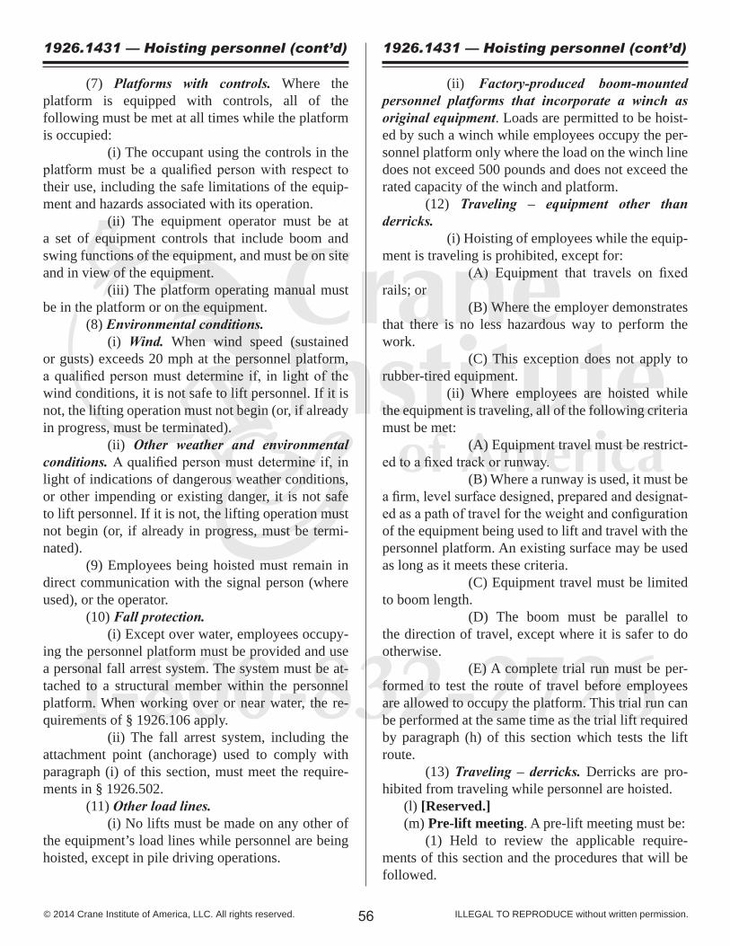
1-800-832-2726
56© 2014 Crane Institute of America, LLC. All rights reserved. ILLEGAL TO REPRODUCE without written permission.
(7) Platforms with controls. Where the platform is equipped with controls, all of the following must be met at all times while the platform is occupied: (i) The occupant using the controls in the platform must be a qualified person with respect to their use, including the safe limitations of the equip-ment and hazards associated with its operation. (ii) The equipment operator must be at a set of equipment controls that include boom and swing functions of the equipment, and must be on site and in view of the equipment. (iii) The platform operating manual must be in the platform or on the equipment. (8) Environmental conditions. (i) Wind. When wind speed (sustained or gusts) exceeds 20 mph at the personnel platform, a qualified person must determine if, in light of the wind conditions, it is not safe to lift personnel. If it is not, the lifting operation must not begin (or, if already in progress, must be terminated). (ii) Other weather and environmental conditions. A qualified person must determine if, in light of indications of dangerous weather conditions, or other impending or existing danger, it is not safe to lift personnel. If it is not, the lifting operation must not begin (or, if already in progress, must be termi-nated). (9) Employees being hoisted must remain in direct communication with the signal person (where used), or the operator. (10) Fall protection. (i) Except over water, employees occupy-ing the personnel platform must be provided and use a personal fall arrest system. The system must be at-tached to a structural member within the personnel platform. When working over or near water, the re-quirements of § 1926.106 apply. (ii) The fall arrest system, including the attachment point (anchorage) used to comply with paragraph (i) of this section, must meet the require-ments in § 1926.502. (11) Other load lines. (i) No lifts must be made on any other of the equipment’s load lines while personnel are being hoisted, except in pile driving operations.
1926.1431 — Hoisting personnel (cont’d) 1926.1431 — Hoisting personnel (cont’d)
(ii) Factory-produced boom-mounted personnel platforms that incorporate a winch as original equipment. Loads are permitted to be hoist-ed by such a winch while employees occupy the per-sonnel platform only where the load on the winch line does not exceed 500 pounds and does not exceed the rated capacity of the winch and platform. (12) Traveling – equipment other than derricks. (i) Hoisting of employees while the equip-ment is traveling is prohibited, except for: (A) Equipment that travels on fixed rails; or (B) Where the employer demonstrates that there is no less hazardous way to perform the work. (C) This exception does not apply to rubber-tired equipment. (ii) Where employees are hoisted while the equipment is traveling, all of the following criteria must be met: (A) Equipment travel must be restrict-ed to a fixed track or runway. (B) Where a runway is used, it must be a firm, level surface designed, prepared and designat-ed as a path of travel for the weight and configuration of the equipment being used to lift and travel with the personnel platform. An existing surface may be used as long as it meets these criteria. (C) Equipment travel must be limited to boom length. (D) The boom must be parallel to the direction of travel, except where it is safer to do otherwise. (E) A complete trial run must be per-formed to test the route of travel before employees are allowed to occupy the platform. This trial run can be performed at the same time as the trial lift required by paragraph (h) of this section which tests the lift route. (13) Traveling – derricks. Derricks are pro-hibited from traveling while personnel are hoisted. (l) [Reserved.] (m) Pre-lift meeting. A pre-lift meeting must be: (1) Held to review the applicable require-ments of this section and the procedures that will be followed.

1-800-832-2726
57© 2014 Crane Institute of America, LLC. All rights reserved. ILLEGAL TO REPRODUCE without written permission.
(2) Attended by the equipment operator, signal person (if used for the lift), employees to be hoisted, and the person responsible for the task to be performed. (3) Held prior to the trial lift at each new work location, and must be repeated for any employees newly assigned to the operation. (n) Hoisting personnel near power lines. Hoist-ing personnel within 20 feet of a power line that is up to 350 kV, and hoisting personnel within 50 feet of a power line that is over 350 kV, is prohibited, except for work covered by subpart V of this part (Power Transmission and Distribution). (o) Hoisting personnel in drill shafts. When hoisting employees into and out of drill shafts that are up to and including 8 feet in diameter, all of the following requirements must be met: (1) The employee must be in either a person-nel platform or on a boatswain’s chair. (2) If using a personnel platform, paragraphs (a) through (n) of this section apply. (3) If using a boatswain’s chair: (i) The following paragraphs of this sec-tion apply: (a), (c), (d)(1), (d)(3), (d)(4), (e)(1), (e)(2), (e)(3), (f)(1), (f)(2)(i), (f)(3)(i), (g), (h), (k)(1), (k)(6), (k)(8), (k)(9), (k)(11)(i), (m), (n). Where the terms “personnel platform” or “platform” are used in these paragraphs, substitute them with “boatswain’s chair.” (ii) A signal person must be stationed at the shaft opening. (iii) The employee must be hoisted in a slow, controlled descent and ascent. (iv) The employee must use personal fall protection equipment, including a full body harness, attached independent of the crane/derrick. (v) The fall protection equipment must meet the applicable requirements in § 1926.502. (vi) The boatswain’s chair itself (exclud-ing the personal fall arrest system anchorages), must be capable of supporting, without failure, its own weight and at least five times the maximum intended load. (vii) No more than one person must be hoisted at a time. (p) Hoisting personnel for pile driving opera-tions. When hoisting an employee in pile driving op-erations, the following requirements must be met:
1926.1431 — Hoisting personnel (cont’d)
(1) The employee must be in a personnel plat-form or boatswain’s chair. (2) For lattice boom cranes: Clearly mark the cable (so that it can easily be seen by the operator) at a point that will give the operator sufficient time to stop the hoist to prevent two-blocking, or use a spot-ter who is in direct communication with the operator to inform the operator when this point is reached. For telescopic boom cranes: Clearly mark the cable (so that it can be easily seen by the operator) at a point that will give the operator sufficient time to stop the hoist to prevent two-blocking, and use a spotter who is in direct communication with the operator to in-form the operator when this point is reached. (3) If using a personnel platform, paragraphs (b) through (n) of this section apply. (4) If using a boatswain’s chair: (i) The following paragraphs of this sec-tion apply: (a), (c), (d)(1), (d)(3), (d)(4), (e)(1), (e)(2), (e)(3), (f)(1), (f)(2)(i), (f)(3)(i), (g), (h), (j), (k)(1), (k)(6), (k)(8), (k)(9), (k)(11)(i), (m), and (n). Where the terms “personnel platform” or “platform” are used in these paragraphs, substitute them with “boatswains chair.” (ii) The employee must be hoisted in a slow, controlled descent and ascent. (iii) The employee must use personal fall protection equipment, including a full body harness, independently attached to the lower load block or overhaul ball. (iv) The fall protection equipment must meet the applicable requirements in § 1926.502. (v) The boatswain’s chair itself (excluding the personal fall arrest system anchorages), must be capable of supporting, without failure, its own weight and at least five times the maximum intended load. (vi) No more than one person must be hoisted at a time. (q) [Reserved.] (r) Hoisting personnel for marine transfer. When hoisting employees solely for transfer to or from a marine worksite, the following requirements must be met: (1) The employee must be in either a person-nel platform or a marine-hoisted personnel transfer device. (2) If using a personnel platform, paragraphs (a) through (n) of this section apply.
1926.1431 — Hoisting personnel (cont’d)

3/8 7/16 1/2 9/16 5/8 3/4 7/8 1 1 1/8 1 1/4 1 3/8 1 1/2 1 5/8 1 3/4
Forged Eye Bolts • Shouldered Type
NominalSize
(inches)90 deg.(pounds)
NR NR 220 520 890 1310 1910 2630 4125 6040
Rigger’s Capacity Card © CIA, LLC.
Crane Institute of America, LLC.www.craneinstitute.com . 3880 St. Johns Parkway, Sanford, Florida 32771 . 407-322-6800
NR NR 180 440 740 1140 1630 2320 3690 5460
Shackles • Screw Pin/Bolt TypeNominalShackle
Size(inches)
WorkingLoadLimit
(pounds) 660 1,000 1,500 2,000 3,000 4,000 6,500 9,500 13,000
NominalShackle
Size(inches)
WorkingLoadLimit
(pounds)
60 deg.(pounds)
Vertical Basket or 2-Leg 60
degree45
degree
Wire Rope Slings • 6 X 19 or 6 X 37 • EIPS • IWRC • MS • Rated Capacity in Pounds
2200 2800 3800 4800 5800 8200 11200 14400 18200 22000 26000 32000 36000 42000
5800 7800 10200 12800 15600 22000 30000 40000 48000 60000 72000 84000 98000 114000
5000 6800 8800 11000 13600 19400 26000 34000 42000 52000 62000 74000 84000 98000
4000 5400 7200 9000 11000 15800 22000 28000 34000 42000 50000 60000 70000 80000
1 LEG BASKET AND 2 LEG BRIDLEChoker
2800 3800 5000 6400 7800 11200 15200 19600 24000 30000 36000 42000 48000 56000
2800 3800 5000 6400 7800 11200 15200 19600 24000 30000 36000 42000 48000 56000
30 degree
RopeDiameter(Inches)
• Rated capacities basket hitch based on D/d ratio of 25.• Rated capacities based on pin diameter no larger than natural eye width or less than the nominal sling diameter.• Horizontal sling angles less than 30 degrees shall not be used.
Alloy Steel Chain Slings • Grade 80 • Rated Capacity in Pounds
2 LEG 3 LEG AND 4 LEG60 deg 45 deg 30 deg 60 deg 45 deg
mm
5.57810131620222632
21003500
4500 7100 12000 18100 28300 34200 47700 72300
ChainSize
(Inches)
7/32 9/32 5/16 3/8 1/2 5/8 3/4 7/8 1 1 1/4
36006100
7800 12300 20800 31300 49000 59200 82600 125200
3000 4900 6400 10000 17000 25600 40000 48400 67400 102200
2100 3500 4500 7100 12000 18100 28300 34200 47700 72300
5500 9100 11700 18400 31200 47000 73500 88900 123900 187800
4400 7400 9500 15100 25500 38400 60000 72500 101200 153400
3200 5200 6800 10600 18000 27100 42400 51300 71500 108400
30 deg
• Chain slings made with grades of steel other than Grades 80 and 100 alloy steel are not recommended for overhead lifting.• Rating of multileg slings adjusted for angle of loading between the inclined leg and the horizontal plane of the load.• 4 leg sling rating is same as 3 leg sling rating because normal lifting practice may not distribute load uniformly on all four legs.
3/16 1/4 5/16 3/8 7/16 1/2 5/8 3/4 7/8
11 1/81 1/41 3/81 1/21 3/4
22 1/42 1/2
17,000 19,000 24,000 27,000 34,000 50,000 70,000 80,000 110,000
1/45/163/81/25/83/47/81
1 1/41 1/2
75 210 400 850 1410 2230 2960 3850 6200 9010
400 680 1000 1840 2940 4340 6000 7880 12600 18260
30 deg.(pounds)
0 deg.(pounds)
7.22.14
rigger’s capacity card - 2014
1 LEG90 deg
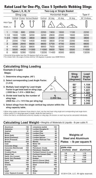
Calculating Sling Loading
Steps:Example (2 Legs):
Sling Load Angle Angle(degrees) Factor 65° 1.104 60° 1.155 55° 1.221 50° 1.305 45° 1.414 40° 1.555 35° 1.742 30° 2.000
Calculating Load Weight • Weights of Materials & Liquids - lb per cubic ft
• When sling angles are between those listed in chart, use the next lower sling angle and corresponding load angle factor.• When using 3 or 4 sling legs equal in length, divide the total load by 3.• When the load is not distributed uniformly (equally) on sling legs, the tension on each leg must be calculated individually.
Weights ofSteel and Aluminum
Plates – lb per square ft
1/8 5 1.75 1/4 10 3.50 1/2 20 7.00 3/4 30 10.50 1 40 14.00
plate size (inches) steel aluminum
Aluminum 165Asbestos 153Asphalt 81Brass 534Brick (Soft) 110Brick (Common) 125Brick (Pressed) 140Bronze 534Coal 84Concrete (Slag) 130Concrete (Reinforced) 150Copper 556Crushed Rock 95Diesel Fuel 52Earth, Dry (Loose) 75Earth, Dry (Packed) 95Earth, Wet 100Glass 161Granite 168Ice 58Iron 485Lead 711Lime: Gypsum (Loose) 64
Limestone (solid) 163Lumber:Douglas-fir 34Lumber:Oak 62Lumber:Pine 45Lumber:Poplar 30Lumber:Spruce 28Lumber:Railroad Ties 50Marble 170Motor Oil 60Paper 75Petroleum: Crude 55Petroleum: Gasoline 45Portland Cement (Loose) 94Portland Cement (Set) 183River Sand 120Rubber 95Sand & Gravel (Wet) 125Sand & Gravel (Dry) 108Steel 490Tar 75Tin 460Water 65Zinc 440
• Horizontal sling angles less than 30 degrees shall not be used.• For choker hitch, the angle of choke shall be 120 degrees or greater (see ASME B30.9)
2,000 lbs.
1. Determine sling angles. (45°)
2. Select corresponding Load Angle Factor. (1.414)
3. Multiply load weight by Load Angle Factor to get total load on sling Legs. ( 2000 lbs x 1.414 = 2828 lbs )4. Divide total load by the number of sling legs. (2828 lbs ÷ 2 = 1414 lbs per sling leg)
5. Select slings from the single vertical leg column within the sling capacity table.
© 2014 CIA, LLC. All rights reserved.