
Procedural modelling in Houdini based on Function ... · Procedural modelling in Houdini based on...
42
Procedural modelling in Houdini based on Function Representation Master’s Thesis Andy Abgottspon August 2011 – National Centre for Computer Animation, Bournemouth University
Transcript of Procedural modelling in Houdini based on Function ... · Procedural modelling in Houdini based on...
Procedural modelling in Houdinibased on Function RepresentationMaster’s ThesisAndy Abgottspon
August 2011 – National Centre for Computer Animation, Bournemouth University
Abstract
In modern computer graphics, objects are mostly represented by boundary representationmodels like polygonal meshes. Such models only store information about an object’s boundaryand are relatively easy to render and often highly scalable. While this is sufficient for avariety of applications like many types of computer animation and games, other uses requireinformation about volume rather than just surface. Function representation (FRep) allowsdefining objects as a set of geometric primitives with certain operations and relations. Sinceobjects are defined as mathematical functions as opposed to a list of points, models areresolution independent and can be polygonised at any desired level of detail.
Building upon the current library developed at the NCCA and its Maya plugin, FRep mod-elling functionality has been integrated into Houdini and its node-based environment. Thelibrary is developed in C++ using the Houdini Development Kit (HDK) and comes as a setof custom nodes.
i
Contents
Abstract i
Table of Contents ii
List of Figures v
Acknowledgements vi
1 Introduction 1
2 Previous work 22.1 Overview of representations . . . . . . . . . . . . . . . . . . . . . . . . . . . . 22.2 The Function Representation (FRep) . . . . . . . . . . . . . . . . . . . . . . . 3
2.2.1 Operations . . . . . . . . . . . . . . . . . . . . . . . . . . . . . . . . . . 32.2.2 Polygonisation . . . . . . . . . . . . . . . . . . . . . . . . . . . . . . . . 4
3 Technical background 53.1 FRep API . . . . . . . . . . . . . . . . . . . . . . . . . . . . . . . . . . . . . . 5
3.1.1 Architectural overview . . . . . . . . . . . . . . . . . . . . . . . . . . . . 53.1.2 Entities and nodes . . . . . . . . . . . . . . . . . . . . . . . . . . . . . . 63.1.3 The FRep tree . . . . . . . . . . . . . . . . . . . . . . . . . . . . . . . . 73.1.4 Usage . . . . . . . . . . . . . . . . . . . . . . . . . . . . . . . . . . . . . 8
3.2 Houdini Development Kit (HDK) . . . . . . . . . . . . . . . . . . . . . . . . . 93.2.1 Extending Houdini . . . . . . . . . . . . . . . . . . . . . . . . . . . . . . 93.2.2 Operators and attributes . . . . . . . . . . . . . . . . . . . . . . . . . . 103.2.3 The SOP Node . . . . . . . . . . . . . . . . . . . . . . . . . . . . . . . . 113.2.4 Geometry . . . . . . . . . . . . . . . . . . . . . . . . . . . . . . . . . . . 12
4 Design and implementation 144.1 System overview . . . . . . . . . . . . . . . . . . . . . . . . . . . . . . . . . . . 144.2 Development environment . . . . . . . . . . . . . . . . . . . . . . . . . . . . . 16
4.2.1 Installation and setup . . . . . . . . . . . . . . . . . . . . . . . . . . . . 164.2.2 Makefiles . . . . . . . . . . . . . . . . . . . . . . . . . . . . . . . . . . . 164.2.3 IDE Integration and debugging . . . . . . . . . . . . . . . . . . . . . . . 16
ii
4.3 Using the FRep API . . . . . . . . . . . . . . . . . . . . . . . . . . . . . . . . 184.3.1 GCC compatibility . . . . . . . . . . . . . . . . . . . . . . . . . . . . . . 184.3.2 Custom intermediate layer . . . . . . . . . . . . . . . . . . . . . . . . . 18
4.4 Procedural function-based modelling in Houdini . . . . . . . . . . . . . . . . . 194.4.1 The modelling workflow . . . . . . . . . . . . . . . . . . . . . . . . . . . 194.4.2 Tree traversal . . . . . . . . . . . . . . . . . . . . . . . . . . . . . . . . . 204.4.3 Polygonisation . . . . . . . . . . . . . . . . . . . . . . . . . . . . . . . . 234.4.4 FRep Operations . . . . . . . . . . . . . . . . . . . . . . . . . . . . . . . 23
5 Results and analysis 295.1 Modelling . . . . . . . . . . . . . . . . . . . . . . . . . . . . . . . . . . . . . . 295.2 Animation . . . . . . . . . . . . . . . . . . . . . . . . . . . . . . . . . . . . . . 305.3 Morphing . . . . . . . . . . . . . . . . . . . . . . . . . . . . . . . . . . . . . . . 315.4 Limitations . . . . . . . . . . . . . . . . . . . . . . . . . . . . . . . . . . . . . . 32
6 Conclusion 336.1 Applications . . . . . . . . . . . . . . . . . . . . . . . . . . . . . . . . . . . . . 336.2 Future work . . . . . . . . . . . . . . . . . . . . . . . . . . . . . . . . . . . . . 34
References 35
iii
List of Figures
2.1 Example of a boundary representation: triangle mesh model . . . . . . . . . . 22.2 Set-theoretic operations based on R-functions: (a) Union and (b) Intersection
(Kravtsov 2011) . . . . . . . . . . . . . . . . . . . . . . . . . . . . . . . . . . . 32.3 Shape and position of 3D blend is controlled by the bounding ellipsoid. (Pasko
et al. 2005) . . . . . . . . . . . . . . . . . . . . . . . . . . . . . . . . . . . . . . 42.4 The leftmost and rightmost images demonstrate the initial and final triangle
surfaces, before and after optimisation. The two middle images show interme-diate stages. (Ohtake et al. 2002) . . . . . . . . . . . . . . . . . . . . . . . . . 4
3.1 Full structure of the modelling environment and basic tools for FRep modelling(Kravtsov 2011) . . . . . . . . . . . . . . . . . . . . . . . . . . . . . . . . . . . 6
3.2 The FRep entity UML-diagram (Kravtsov 2011) . . . . . . . . . . . . . . . . . 73.3 FRep tree in Houdini . . . . . . . . . . . . . . . . . . . . . . . . . . . . . . . . 83.4 A Model-View-Controller diagram: The general design pattern (Kravtsov 2011) 93.5 Houdini’s node based system . . . . . . . . . . . . . . . . . . . . . . . . . . . . 103.6 Basic class diagram for custom Houdini nodes (adapted from SideFX (2011a)) 113.7 Providing guide geometry (blue lattice) in a custom node . . . . . . . . . . . . 123.8 Geometry Structure in Houdini (SideFX 2011b) . . . . . . . . . . . . . . . . . 13
4.1 Class diagram of custom Houdini nodes . . . . . . . . . . . . . . . . . . . . . . 154.2 Using custom build steps in QtCreator to compile and bundle the Houdini
library from within the IDE . . . . . . . . . . . . . . . . . . . . . . . . . . . . 174.3 Debugging using QtCreator . . . . . . . . . . . . . . . . . . . . . . . . . . . . 184.4 The interaction with the FRep API (Kravtsov 2011) . . . . . . . . . . . . . . 194.5 Using built-in primitive types as guide geometry . . . . . . . . . . . . . . . . . 204.6 Transform node for scale, translation and rotation . . . . . . . . . . . . . . . . 204.7 Polygonisation using analytic normals and a subdivision level of 3 . . . . . . . 234.8 Example of a CSG node used to perform a subtract operation . . . . . . . . . 244.9 Example of the blend node in use with different blend values: 1 10 1, 1 50 50,
1 1 10 . . . . . . . . . . . . . . . . . . . . . . . . . . . . . . . . . . . . . . . . . 244.10 Bounded blending using three spheres . . . . . . . . . . . . . . . . . . . . . . . 254.11 Example of the taper node . . . . . . . . . . . . . . . . . . . . . . . . . . . . . 254.12 Examples of bend, twist and deform point operations . . . . . . . . . . . . . . 26
iv
4.13 Sphere sweep node using a standard Houdini curve as input . . . . . . . . . . 264.14 Offset node using different offset values: -0.5 (left), 0 (middle), 0.5 (right) . . . 274.15 Metamorphosis from a cone to a torus . . . . . . . . . . . . . . . . . . . . . . . 274.16 Instancer node output based on torus . . . . . . . . . . . . . . . . . . . . . . . 284.17 More complex example of the instancer node. . . . . . . . . . . . . . . . . . . 28
5.1 Screw model with its corresponding node network and optimisation for sharpfeatures . . . . . . . . . . . . . . . . . . . . . . . . . . . . . . . . . . . . . . . . 29
5.2 Penguin FRep model . . . . . . . . . . . . . . . . . . . . . . . . . . . . . . . . 305.3 Truck showing keyframe animation . . . . . . . . . . . . . . . . . . . . . . . . 305.4 Animation graph of the truck animation . . . . . . . . . . . . . . . . . . . . . 315.5 Metamorphosis of simple 3D character to a screw . . . . . . . . . . . . . . . . 31
6.1 A set of application and platform specific translators (Kravtsov 2011) . . . . . 34
v

Acknowledgements
I would like to express my gratitude towards the course leader Jon Macey for his supportand inputs throughout the academic year and this project.
I thank Denis Kravtsov for providing me with the idea and base for this project, as well asfor his patient and kind support.
Also, thanks to Turlif Vilbrandt from Uformia AS and Prof. Alexander Pasko for theirvaluable feedback and interest in the project.
vi
Chapter 1
Introduction
In the visual effects and games industry, the predominant modelling techniques are usingpolygonal meshes. While these offer various benefits and are well integrated into currentpipelines, they only represent surfaces and have a given amount of detail. As a consequence,information about an object internal structure cannot be stored and modelling of heteroge-neous real-world objects is difficult. In other fields like CAD and 3D printing, the tradeoffscannot be circumvented without effort and alternative representations are needed.
One alternative is to use “Function representation in geometric modelling” as suggested byPasko et al. (1995). The so-called FRep allows the definition of objects, operations andrelations as a mathematical function as opposed to point data and meshes. A lot of researchin this field has been done at the NCCA. The FRep API (Kravtsov 2011) was taken as basefor this project.
This thesis documents the design and implementation of a custom plugin for Houdini thatwas written in C++ using the Houdini Development Kit (HDK). Houdini is a high-end 3Danimation package developed by Side Effects Software and used heavily in the VFX industry.Due to its node-based architecture, it is very suitable for procedural modelling. Moreover,many of the concepts in the FRep API, like for example the tree and node structure, translateand integrate very well into the software.
Chapter 2 gives an overview of the topic and related research. In Chapter 3, the relevantconcepts of the APIs used, namely the existing FRep API and the Houdini Development Kit,are introduced. Chapter 4 documents the conceptual design of the plugin and further detailsparticular to the development environment and workflow. Furthermore, the modelling processand key algorithms are explained. Chapter 5 presents results and gives an idea over potentialapplications. The results are evaluated in Chapter 6 where future work and improvementsare discussed.
1
Chapter 2
Previous work
There are different ways of representing objects digitally. This chapter gives a brief overviewof various representations and discusses the fundamental research relevant for this project.
2.1 Overview of representations
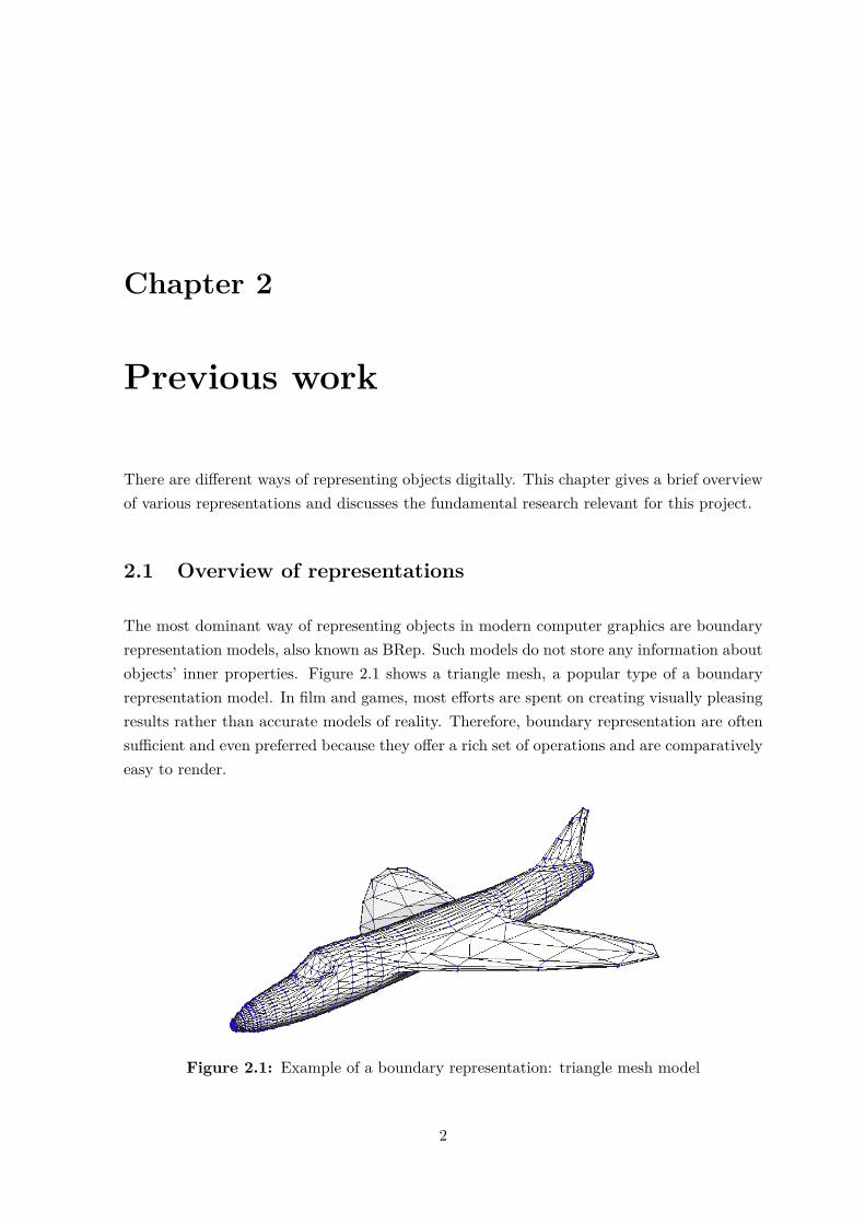
The most dominant way of representing objects in modern computer graphics are boundaryrepresentation models, also known as BRep. Such models do not store any information aboutobjects’ inner properties. Figure 2.1 shows a triangle mesh, a popular type of a boundaryrepresentation model. In film and games, most efforts are spent on creating visually pleasingresults rather than accurate models of reality. Therefore, boundary representation are oftensufficient and even preferred because they offer a rich set of operations and are comparativelyeasy to render.
Figure 2.1: Example of a boundary representation: triangle mesh model
2
2.2 The Function Representation (FRep)
For other purposes, volumetric representations allow us to store the object’s internal structurerather than only a limited surface information. This is especially important when modellingreal-life heterogeneous objects. There are a number of volumetric representations includingvoxel representation, implicit surfaces and FReps.
2.2 The Function Representation (FRep)
The Function Representation (FRep) combines different models such as algebraic surfaces,skeleton based “implicit” surfaces, CSG (Constructive Solid Geometry), sweeps, volumetricobjects, parametric models and procedural models. The representation defines a geometricobject by a single real continuous function of point coordinates as F (X) ≥ 0 (Pasko 2011).This also lets us represent models independent from resolution.
A constructive tree defines functions and provides a visual overview of operations and pa-rameters. Leaf nodes are primitives like a box, sphere, torus, etc. Non-leaf nodes containoperations and relations. This functionality was implemented and made accessible via anFRep API.
2.2.1 Operations
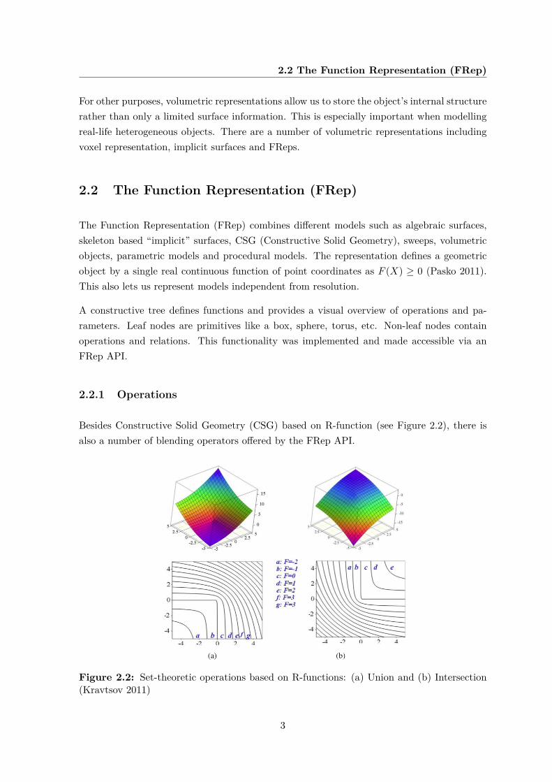
Besides Constructive Solid Geometry (CSG) based on R-function (see Figure 2.2), there isalso a number of blending operators offered by the FRep API.
Figure 2.2: Set-theoretic operations based on R-functions: (a) Union and (b) Intersection(Kravtsov 2011)
3
2.2 The Function Representation (FRep)
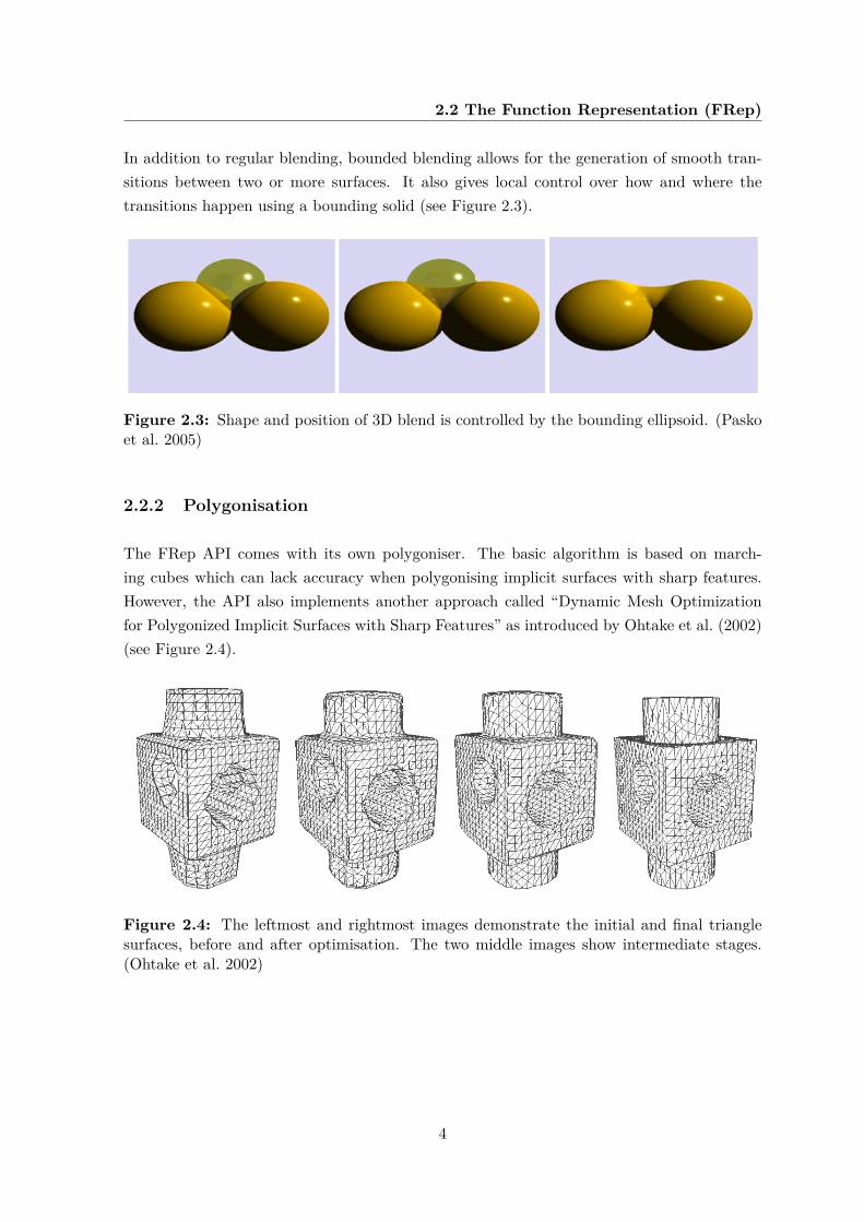
In addition to regular blending, bounded blending allows for the generation of smooth tran-sitions between two or more surfaces. It also gives local control over how and where thetransitions happen using a bounding solid (see Figure 2.3).
Figure 2.3: Shape and position of 3D blend is controlled by the bounding ellipsoid. (Paskoet al. 2005)
2.2.2 Polygonisation
The FRep API comes with its own polygoniser. The basic algorithm is based on march-ing cubes which can lack accuracy when polygonising implicit surfaces with sharp features.However, the API also implements another approach called “Dynamic Mesh Optimizationfor Polygonized Implicit Surfaces with Sharp Features” as introduced by Ohtake et al. (2002)(see Figure 2.4).
Figure 2.4: The leftmost and rightmost images demonstrate the initial and final trianglesurfaces, before and after optimisation. The two middle images show intermediate stages.(Ohtake et al. 2002)
4
Chapter 3
Technical background
Working with 3rd party code and frameworks can be challenging. Along with the technicaldetails, a fair understanding of the overall environment is required to make the right designdecisions later. This chapter gives an overview of the FRep API and the key HDK conceptsrelevant to this project.
3.1 FRep API
This project is using the FRep API developed by (Kravtsov 2011). He describes the commu-nication between API and applications as follows:
“The main and most common way of communication between the FRep APIand higher-level applications using FReps is through the parameters of the FRepentities and through the creation of complex FRep trees containing the aforemen-tioned entities.” (Kravtsov 2011)
3.1.1 Architectural overview
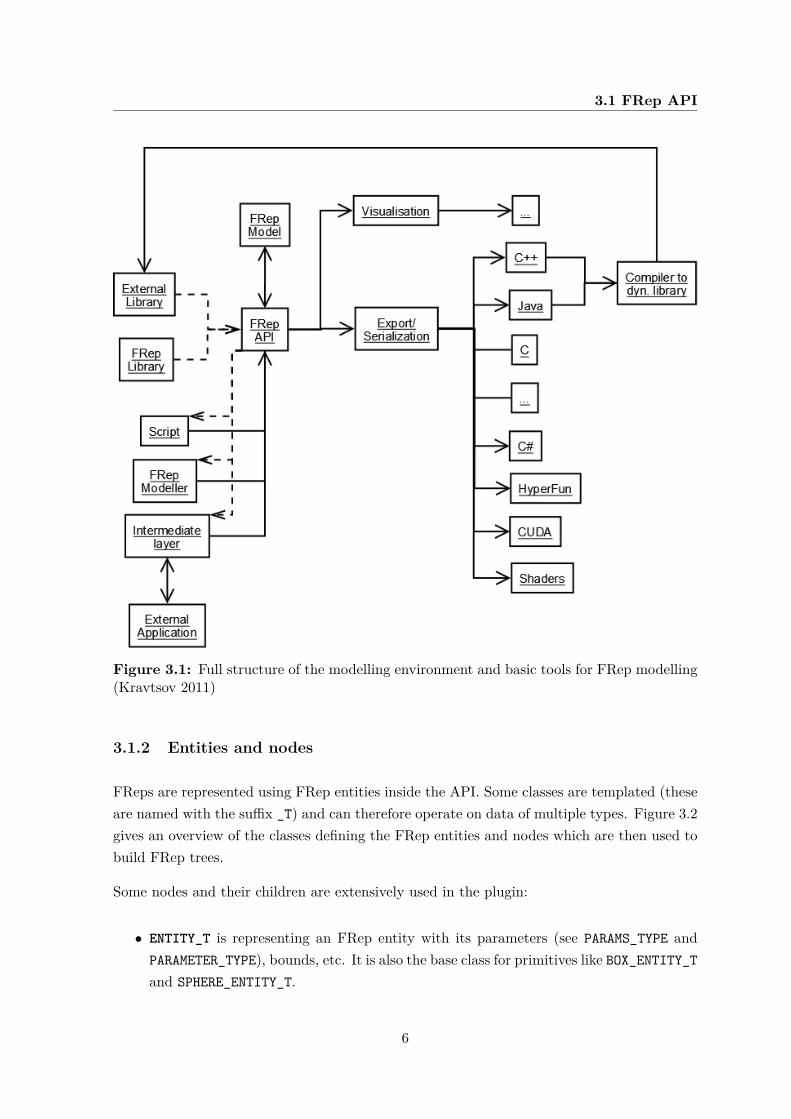
The FRep API itself makes use of a number of libraries and underlying APIs. Figure 3.1shows the API in the context and in relation to the intermediate layer. The plugin developedacts as intermediate layer between the external application (Houdini) and the API.
5
3.1 FRep API
Figure 3.1: Full structure of the modelling environment and basic tools for FRep modelling(Kravtsov 2011)
3.1.2 Entities and nodes
FReps are represented using FRep entities inside the API. Some classes are templated (theseare named with the suffix _T) and can therefore operate on data of multiple types. Figure 3.2gives an overview of the classes defining the FRep entities and nodes which are then used tobuild FRep trees.
Some nodes and their children are extensively used in the plugin:
• ENTITY_T is representing an FRep entity with its parameters (see PARAMS_TYPE andPARAMETER_TYPE), bounds, etc. It is also the base class for primitives like BOX_ENTITY_Tand SPHERE_ENTITY_T.
6
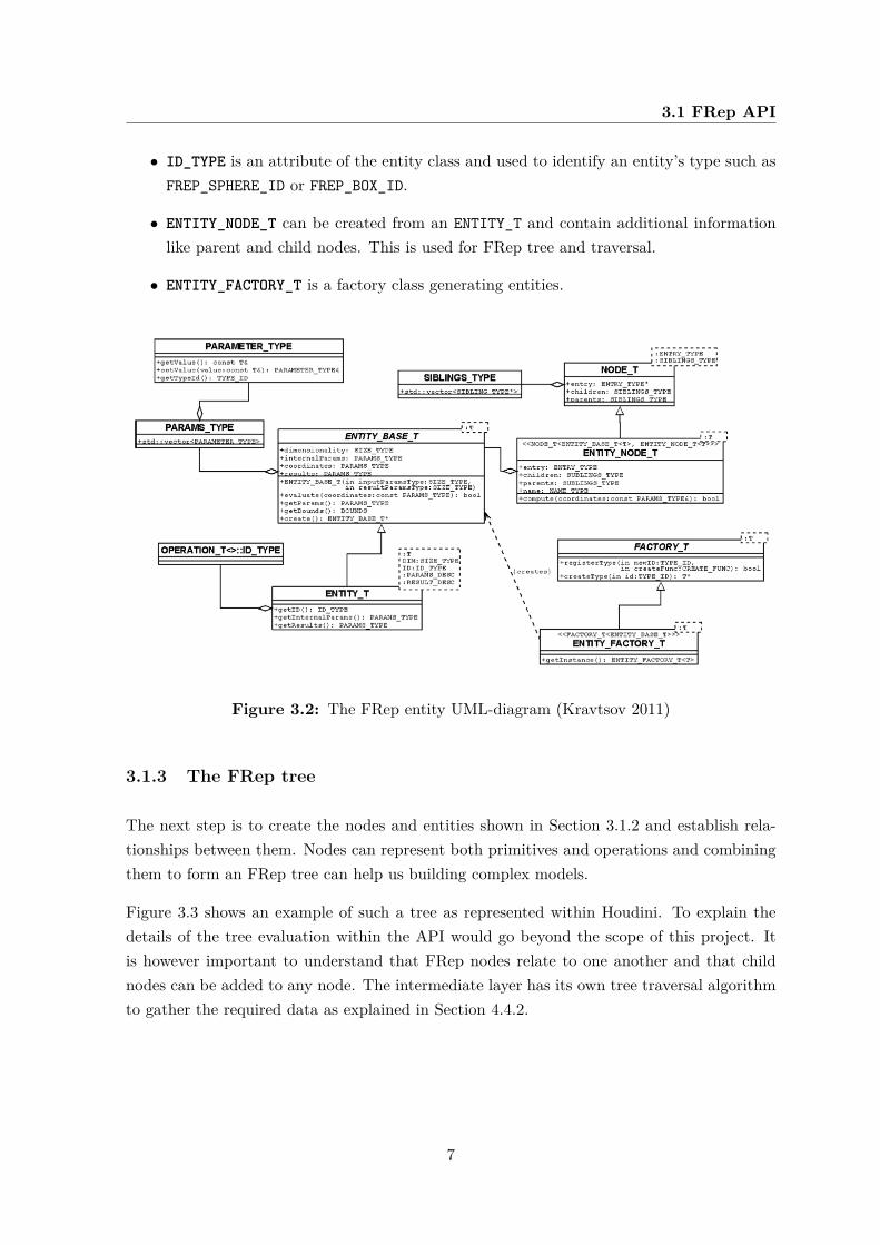
3.1 FRep API
• ID_TYPE is an attribute of the entity class and used to identify an entity’s type such asFREP_SPHERE_ID or FREP_BOX_ID.
• ENTITY_NODE_T can be created from an ENTITY_T and contain additional informationlike parent and child nodes. This is used for FRep tree and traversal.
• ENTITY_FACTORY_T is a factory class generating entities.
Figure 3.2: The FRep entity UML-diagram (Kravtsov 2011)
3.1.3 The FRep tree
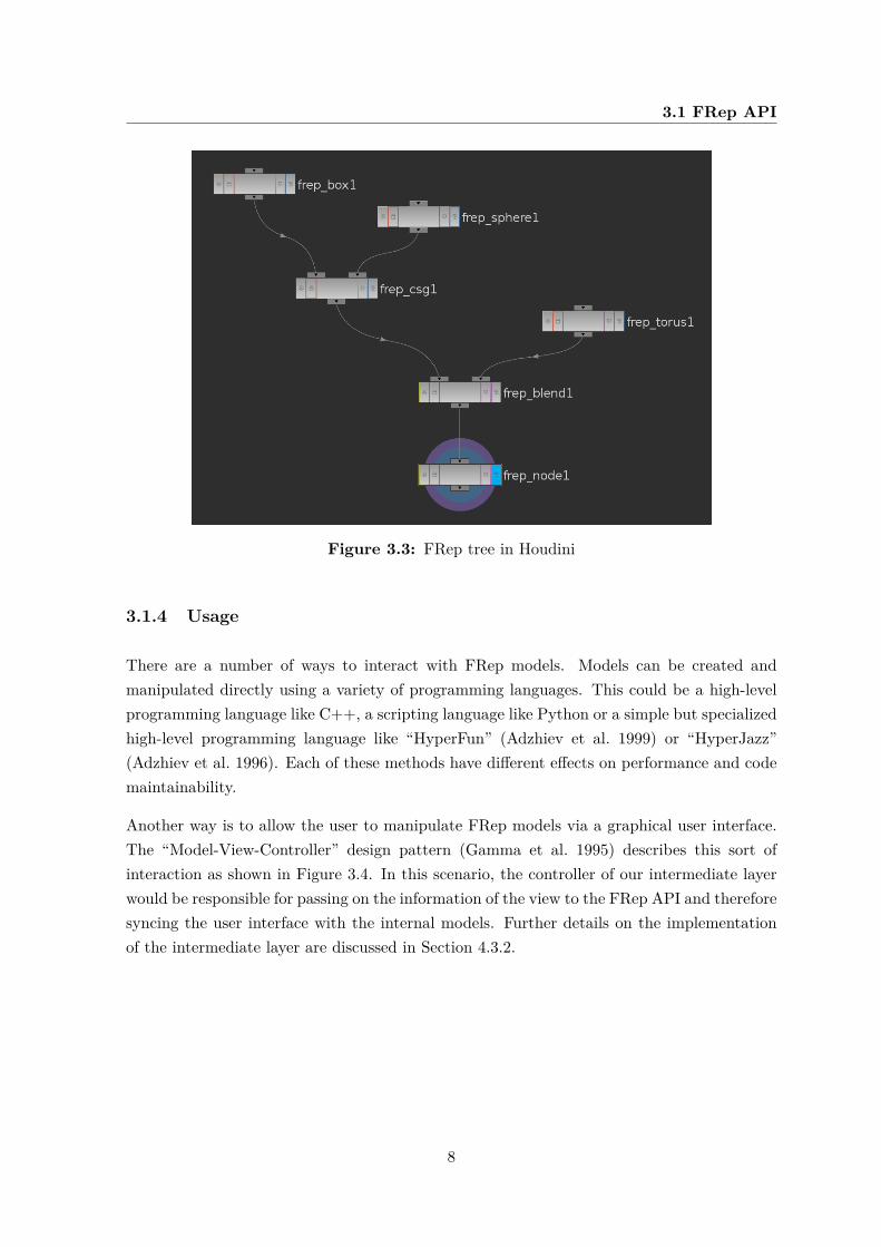
The next step is to create the nodes and entities shown in Section 3.1.2 and establish rela-tionships between them. Nodes can represent both primitives and operations and combiningthem to form an FRep tree can help us building complex models.
Figure 3.3 shows an example of such a tree as represented within Houdini. To explain thedetails of the tree evaluation within the API would go beyond the scope of this project. Itis however important to understand that FRep nodes relate to one another and that childnodes can be added to any node. The intermediate layer has its own tree traversal algorithmto gather the required data as explained in Section 4.4.2.
7
3.1 FRep API
Figure 3.3: FRep tree in Houdini
3.1.4 Usage
There are a number of ways to interact with FRep models. Models can be created andmanipulated directly using a variety of programming languages. This could be a high-levelprogramming language like C++, a scripting language like Python or a simple but specializedhigh-level programming language like “HyperFun” (Adzhiev et al. 1999) or “HyperJazz”(Adzhiev et al. 1996). Each of these methods have different effects on performance and codemaintainability.
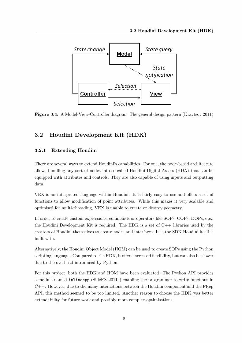
Another way is to allow the user to manipulate FRep models via a graphical user interface.The “Model-View-Controller” design pattern (Gamma et al. 1995) describes this sort ofinteraction as shown in Figure 3.4. In this scenario, the controller of our intermediate layerwould be responsible for passing on the information of the view to the FRep API and thereforesyncing the user interface with the internal models. Further details on the implementationof the intermediate layer are discussed in Section 4.3.2.
8
3.2 Houdini Development Kit (HDK)
Figure 3.4: A Model-View-Controller diagram: The general design pattern (Kravtsov 2011)
3.2 Houdini Development Kit (HDK)
3.2.1 Extending Houdini
There are several ways to extend Houdini’s capabilities. For one, the node-based architectureallows bundling any sort of nodes into so-called Houdini Digital Assets (HDA) that can beequipped with attributes and controls. They are also capable of using inputs and outputtingdata.
VEX is an interpreted language within Houdini. It is fairly easy to use and offers a set offunctions to allow modification of point attributes. While this makes it very scalable andoptimised for multi-threading, VEX is unable to create or destroy geometry.
In order to create custom expressions, commands or operators like SOPs, COPs, DOPs, etc.,the Houdini Development Kit is required. The HDK is a set of C++ libraries used by thecreators of Houdini themselves to create nodes and interfaces. It is the SDK Houdini itself isbuilt with.
Alternatively, the Houdini Object Model (HOM) can be used to create SOPs using the Pythonscripting language. Compared to the HDK, it offers increased flexibility, but can also be slowerdue to the overhead introduced by Python.
For this project, both the HDK and HOM have been evaluated. The Python API providesa module named inlinecpp (SideFX 2011c) enabling the programmer to write functions inC++. However, due to the many interactions between the Houdini component and the FRepAPI, this method seemed to be too limited. Another reason to choose the HDK was betterextendability for future work and possibly more complex optimisations.
9
3.2 Houdini Development Kit (HDK)
3.2.2 Operators and attributes
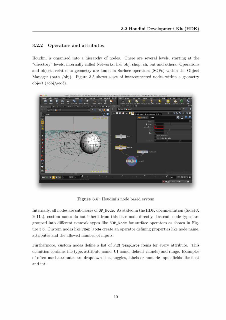
Houdini is organised into a hierarchy of nodes. There are several levels, starting at the“directory” levels, internally called Networks, like obj, shop, ch, out and others. Operationsand objects related to geometry are found in Surface operators (SOPs) within the ObjectManager (path /obj). Figure 3.5 shows a set of interconnected nodes within a geometryobject (/obj/geo3).
Figure 3.5: Houdini’s node based system
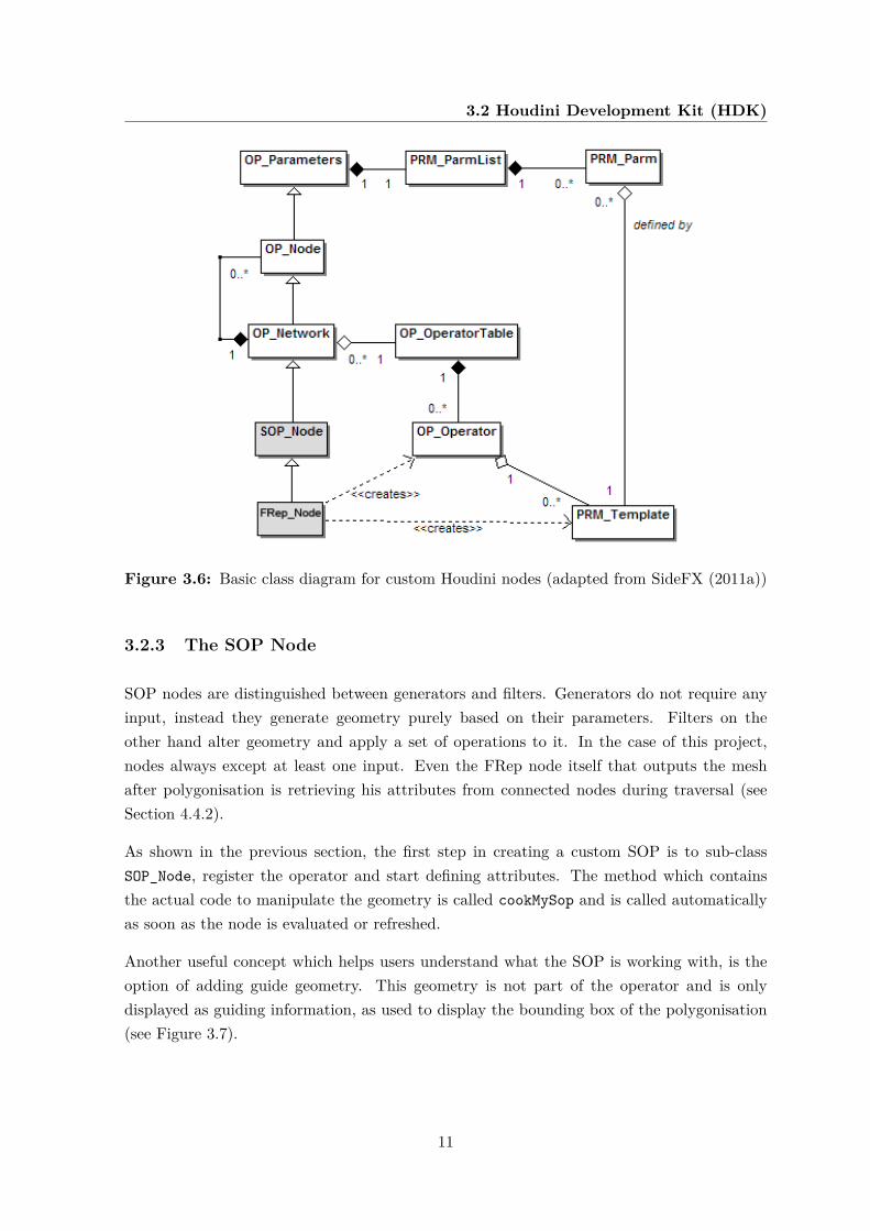
Internally, all nodes are subclasses of OP_Node. As stated in the HDK documentation (SideFX2011a), custom nodes do not inherit from this base node directly. Instead, node types aregrouped into different network types like SOP_Node for surface operators as shown in Fig-ure 3.6. Custom nodes like FRep_Node create an operator defining properties like node name,attributes and the allowed number of inputs.
Furthermore, custom nodes define a list of PRM_Template items for every attribute. Thisdefinition contains the type, attribute name, UI name, default value(s) and range. Examplesof often used attributes are dropdown lists, toggles, labels or numeric input fields like floatand int.
10
3.2 Houdini Development Kit (HDK)
Figure 3.6: Basic class diagram for custom Houdini nodes (adapted from SideFX (2011a))
3.2.3 The SOP Node
SOP nodes are distinguished between generators and filters. Generators do not require anyinput, instead they generate geometry purely based on their parameters. Filters on theother hand alter geometry and apply a set of operations to it. In the case of this project,nodes always except at least one input. Even the FRep node itself that outputs the meshafter polygonisation is retrieving his attributes from connected nodes during traversal (seeSection 4.4.2).
As shown in the previous section, the first step in creating a custom SOP is to sub-classSOP_Node, register the operator and start defining attributes. The method which containsthe actual code to manipulate the geometry is called cookMySop and is called automaticallyas soon as the node is evaluated or refreshed.
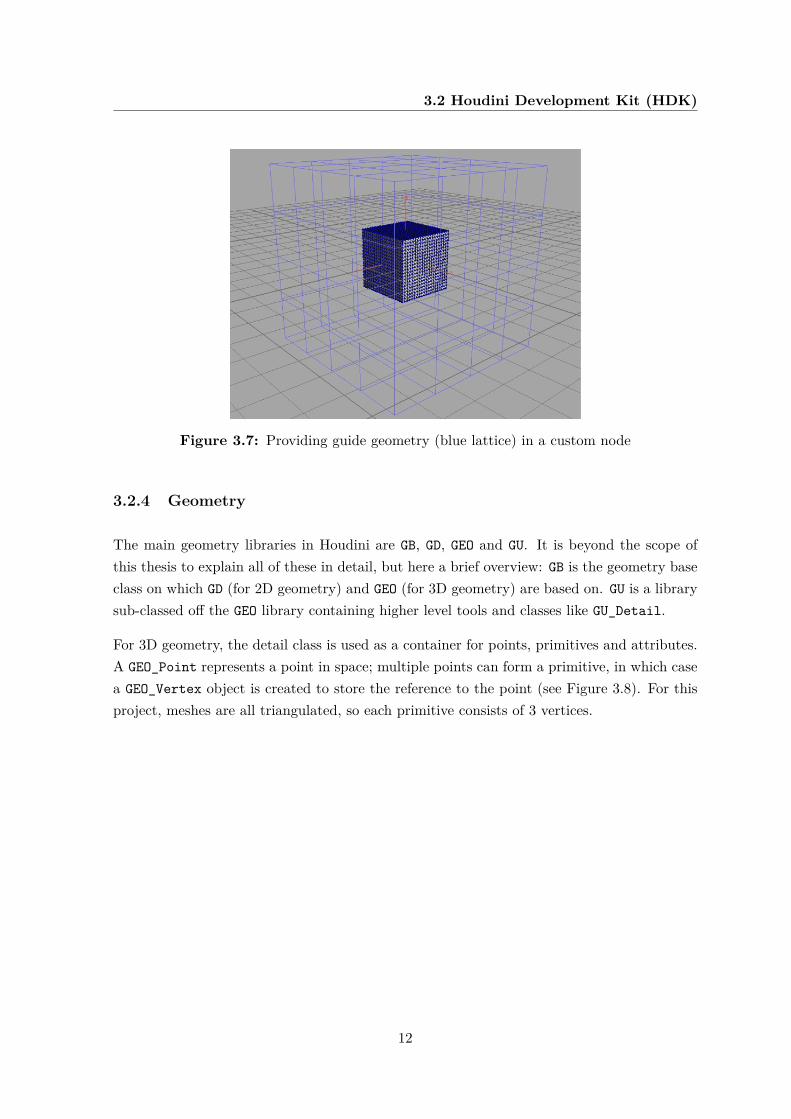
Another useful concept which helps users understand what the SOP is working with, is theoption of adding guide geometry. This geometry is not part of the operator and is onlydisplayed as guiding information, as used to display the bounding box of the polygonisation(see Figure 3.7).
11
3.2 Houdini Development Kit (HDK)
Figure 3.7: Providing guide geometry (blue lattice) in a custom node
3.2.4 Geometry
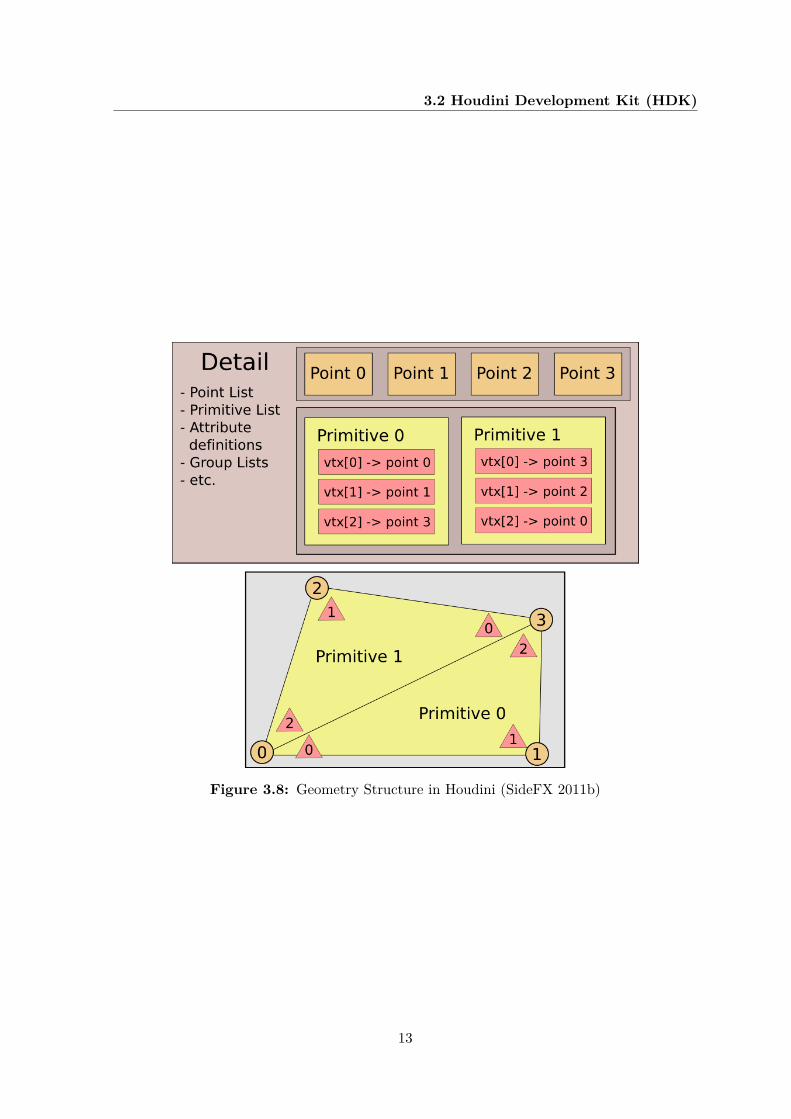
The main geometry libraries in Houdini are GB, GD, GEO and GU. It is beyond the scope ofthis thesis to explain all of these in detail, but here a brief overview: GB is the geometry baseclass on which GD (for 2D geometry) and GEO (for 3D geometry) are based on. GU is a librarysub-classed off the GEO library containing higher level tools and classes like GU_Detail.
For 3D geometry, the detail class is used as a container for points, primitives and attributes.A GEO_Point represents a point in space; multiple points can form a primitive, in which casea GEO_Vertex object is created to store the reference to the point (see Figure 3.8). For thisproject, meshes are all triangulated, so each primitive consists of 3 vertices.
12
3.2 Houdini Development Kit (HDK)
Figure 3.8: Geometry Structure in Houdini (SideFX 2011b)
13
Chapter 4
Design and implementation
To design a system well requires knowledge of all components and appropriate use of thetools at disposal. After all, design is not just what something looks like, it is how it works.
Many design decisions made throughout the project were based on best practises and exam-ples from Houdini and its HDK. The main goal was to integrate FRep modelling capabilitiesinto a environment familiar to existing Houdini users rather than inventing complicated newworkflows.
4.1 System overview
General naming conventions and coding standards have been respected and kept consistentwith the Maya plugin and FRep library itself, wherever possible and not conflicting withHDK’s coding guidelines.
There are three main QtCreator projects:
• QtRep: The port of the FRep API from Windows to Mac OS X (see Section 4.3.1 onGCC compatibility). The output is a dynamic library libQtRep.dylib on Mac OS.On Windows, this would correspond to a .dll, on Linux to a .so file.
• frep-houdini: The intermediate layer (see Section 3.1.1), making use of libQtRep.dylib and containing all custom FRep nodes for Houdini.
• houdini-test: A standalone test project that uses libQtRep.dylib and allows to makecalls to the FRep API. This is useful for testing and debugging the interaction with theFRep library.
14
4.1 System overview
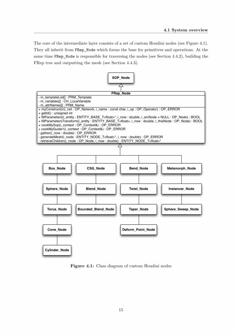
The core of the intermediate layer consists of a set of custom Houdini nodes (see Figure 4.1).They all inherit from FRep_Node which forms the base for primitives and operations. At thesame time FRep_Node is responsible for traversing the nodes (see Section 4.4.2), building theFRep tree and outputting the mesh (see Section 4.4.3).
+ myConstructor(i_net : OP_Network, i_name : const char, i_op : OP_Operator) : OP_ERROR+ getId() : unsigned int+ fillParameters(i_entity : ENTITY_BASE_T<float>*, i_now : double, i_srcNode = NULL : OP_Node) : BOOL+ fillParametersTransform(i_entity : ENTITY_BASE_T<float>, i_now : double, i_thisNode : OP_Node) : BOOL+ cookMySop(i_context : OP_Context&) : OP_ERROR+ cookMyGuide1(i_context : OP_Context&) : OP_ERROR- gather(i_now : double) : OP_ERROR- generateMesh(i_node : ENTITY_NODE_T<float>*, i_now : double) : OP_ERROR- retrieveChildren(i_node : OP_Node, i_now : double) : ENTITY_NODE_T<float>*
- m_templateList[] : PRM_Template- m_variables[] : CH_LocalVariable- m_attrNames[] : PRM_Name
FRep_Node
Box_Node CSG_Node Bend_Node Metamorph_Node
SOP_Node
Sphere_Node
Torus_Node
Cone_Node
Cylinder_Node
Blend_Node
Bounded_Blend_Node
Twist_Node
Taper_Node
Deform_Point_Node
Instancer_Node
Sphere_Sweep_Node
Figure 4.1: Class diagram of custom Houdini nodes
15
4.2 Development environment
4.2 Development environment
4.2.1 Installation and setup
The Houdini Development Kit (HDK) is part of Houdini and installed under $HFS/toolkit.All required header files, makefiles and samples are available in Houdini Master as well asthe free Apprentice version. This project was developed using QtCreator in order to allowdeployment to other platforms. The operating system used during development was Mac OSX 10.7.
After the installation, the $HFS environment variable points to the installation directory,which is typically /Library/Frameworks/Houdini.framework/Resources on a Mac.
4.2.2 Makefiles
There are several ways of compiling HDK code. Using the hcustom command-line tool is veryconvenient and useful for testing, but also limited to a single C++ source file and thereforenot appropriate for the library. The alternative is using Makefiles which are shipped withthe HDK and provide sample Makefiles for Linux and Windows.
For the Mac, Schmidt (2011) provides a makefile which was used as a base. Additionally,running hcustom -e My_Node.cpp outputs the compiler and linker commands executed byhcustom and offers an insight into the way plugins are compiled and bundled. This is par-ticularly helpful when compiling from console or for debugging compiler and linker flags.
4.2.3 IDE Integration and debugging
It is worth mentioning a number of best practices that have been discovered throughout thedevelopment, especially since effective workflows on different platforms using various IDEsare scarcely documented.
Unfortunately, Houdini’s plugin architecture does not (officially) support loading and reload-ing of plugins. Instead, they are loaded upon startup which requires Houdini to be closed andreopened every time a change to a library is made. During the development of the project,the following workflow has proven to be most effective:
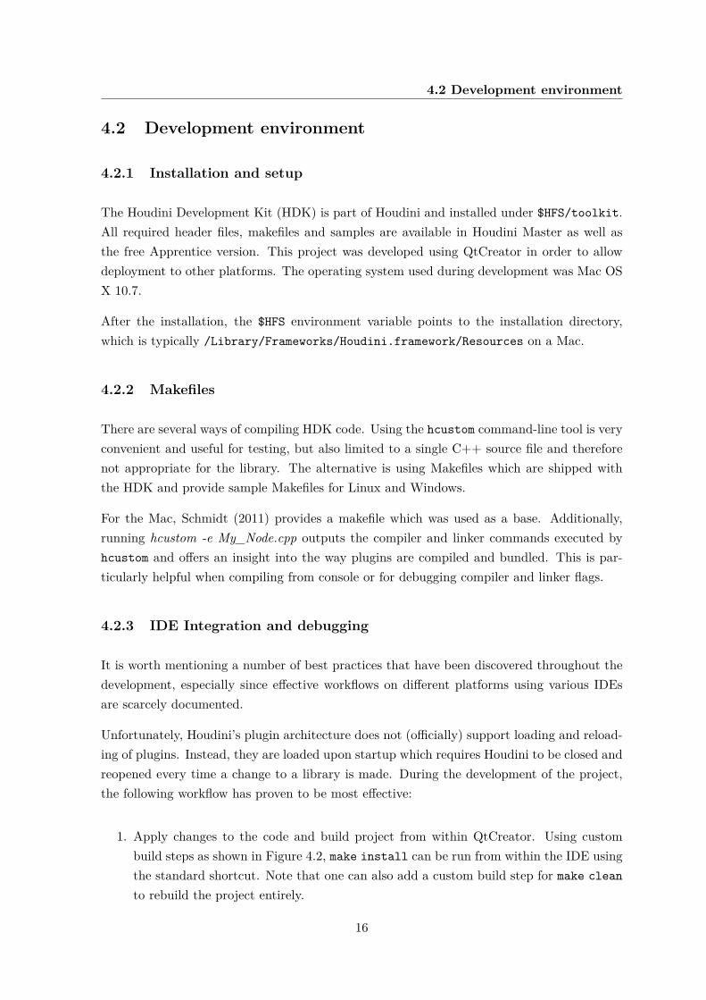
1. Apply changes to the code and build project from within QtCreator. Using custombuild steps as shown in Figure 4.2, make install can be run from within the IDE usingthe standard shortcut. Note that one can also add a custom build step for make cleanto rebuild the project entirely.
16
4.2 Development environment
2. Start Houdini from Terminal. This could also be done automatically via a custom buildstep. However, the terminal window is at the same time used for logs and thereforeuseful to display.
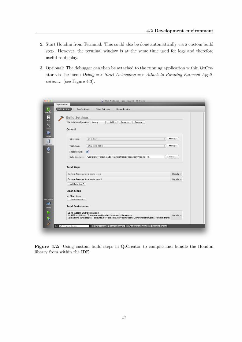
3. Optional: The debugger can then be attached to the running application within QtCre-ator via the menu Debug => Start Debugging => Attach to Running External Appli-cation... (see Figure 4.3).
Figure 4.2: Using custom build steps in QtCreator to compile and bundle the Houdinilibrary from within the IDE
17
4.3 Using the FRep API
Figure 4.3: Debugging using QtCreator
4.3 Using the FRep API
4.3.1 GCC compatibility
Various adjustments to the existing FRep library (see Section 3.1) were required for it to beused in the HDK plugin. A dynamic library was built and the code, originally developed onWindows using Visual Studio’s compiler, was made GCC compatible.
This very time-consuming task was at the same time necessary groundwork. Having astandard-compliant code base then allows for cross-platform development. The original li-brary heavily relies on templates and some notations needed to be adjusted in order to workwith the usually more strict GCC. Although being platform-independent for the most part,some platform-specific code in the FRep library had to be ported as well.
4.3.2 Custom intermediate layer
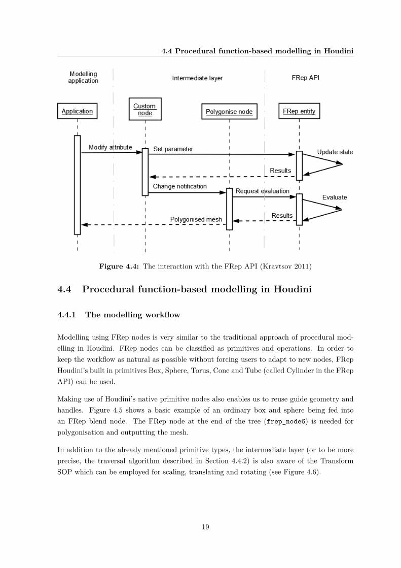
The set of Houdini operators create a custom intermediate layer, allowing communicationbetween FRep API and Houdini (see Figure 4.4). These patterns were adapted from the ex-isting plugin for Autodesk Maya (Kravtsov 2011). Furthermore, existing naming conventionswere kept and pre-existing standards respected to ensure portability and maintainability.
18
4.4 Procedural function-based modelling in Houdini
Figure 4.4: The interaction with the FRep API (Kravtsov 2011)
4.4 Procedural function-based modelling in Houdini
4.4.1 The modelling workflow
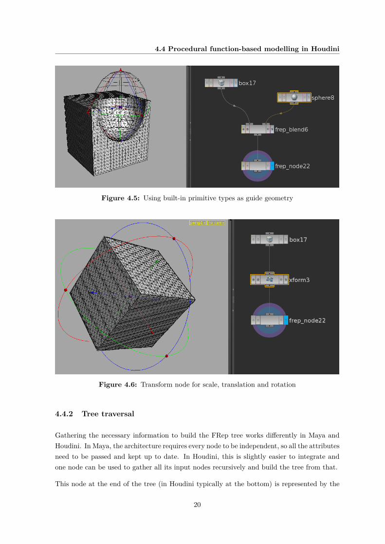
Modelling using FRep nodes is very similar to the traditional approach of procedural mod-elling in Houdini. FRep nodes can be classified as primitives and operations. In order tokeep the workflow as natural as possible without forcing users to adapt to new nodes, FRepHoudini’s built in primitives Box, Sphere, Torus, Cone and Tube (called Cylinder in the FRepAPI) can be used.
Making use of Houdini’s native primitive nodes also enables us to reuse guide geometry andhandles. Figure 4.5 shows a basic example of an ordinary box and sphere being fed intoan FRep blend node. The FRep node at the end of the tree (frep_node6) is needed forpolygonisation and outputting the mesh.
In addition to the already mentioned primitive types, the intermediate layer (or to be moreprecise, the traversal algorithm described in Section 4.4.2) is also aware of the TransformSOP which can be employed for scaling, translating and rotating (see Figure 4.6).
19
4.4 Procedural function-based modelling in Houdini
Figure 4.5: Using built-in primitive types as guide geometry
Figure 4.6: Transform node for scale, translation and rotation
4.4.2 Tree traversal
Gathering the necessary information to build the FRep tree works differently in Maya andHoudini. In Maya, the architecture requires every node to be independent, so all the attributesneed to be passed and kept up to date. In Houdini, this is slightly easier to integrate andone node can be used to gather all its input nodes recursively and build the tree from that.
This node at the end of the tree (in Houdini typically at the bottom) is represented by the
20
4.4 Procedural function-based modelling in Houdini
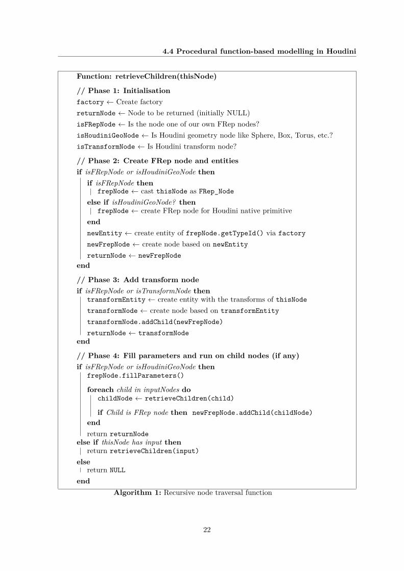
FRep_Node class. The traversal of the nodes is controlled by one single, recursive functioncalled retrieveChildren. Not only is this function responsible for traversing all child nodes,it also creates the corresponding FRep entities and nodes as well as fills them with theparameters provided by the user in Houdini.
The function is run with the (only) child of the FRep_Node as input and returns a full FReptree consisting of FRep nodes and their children. The algorithm (see Algorithm 1) can bestructured in five phases:
1. Variables like factory and returnNode are initialised. Also, further flags to indicatethe type of the current node are defined.
2. A new frepNode instance is created. This is achieved either by casting the currentnode, if it is an actual FRep node, or by manually creating it in case the current nodeis one of Houdini’s built-in primitives (Sphere, Box, Torus, Cone, etc.). Additionally, anew FRep entity of the corresponding type is created. The node holding that entity isalso marked to be returned.
3. The FRep API offers a transform entity which can be appended to a node to per-form operations. In case we are using an FRep node that can be transformed or evenHoudini’s own transform SOP, create the necessary FRep entity. Then, create the cor-responding node and add it as child of the original node. In this manner, an “invisible”FRep transform is added right after the node it transforms.
4. In the last step, the algorithms determines what to return. If the current node is anFRep object (either by being one of the FRep nodes or one of Houdini’s primitivesrepresenting one), fill the entity and run this whole procedure for every child of thisnode. Alternatively, if this is just an ordinary node that should be ignored by thissystem, run retrieveChildren on its input (child). If the node is irrelevant to theFRep system and has no inputs, return NULL.
21
4.4 Procedural function-based modelling in Houdini
Function: retrieveChildren(thisNode)
// Phase 1: Initialisationfactory ← Create factoryreturnNode ← Node to be returned (initially NULL)isFRepNode ← Is the node one of our own FRep nodes?isHoudiniGeoNode ← Is Houdini geometry node like Sphere, Box, Torus, etc.?isTransformNode ← Is Houdini transform node?
// Phase 2: Create FRep node and entitiesif isFRepNode or isHoudiniGeoNode then
if isFRepNode thenfrepNode ← cast thisNode as FRep_Node
else if isHoudiniGeoNode? thenfrepNode ← create FRep node for Houdini native primitive
endnewEntity ← create entity of frepNode.getTypeId() via factorynewFrepNode ← create node based on newEntityreturnNode ← newFrepNode
end
// Phase 3: Add transform nodeif isFRepNode or isTransformNode then
transformEntity ← create entity with the transforms of thisNodetransformNode ← create node based on transformEntitytransformNode.addChild(newFrepNode)returnNode ← transformNode
end
// Phase 4: Fill parameters and run on child nodes (if any)if isFRepNode or isHoudiniGeoNode then
frepNode.fillParameters()
foreach child in inputNodes dochildNode ← retrieveChildren(child)
if Child is FRep node then newFrepNode.addChild(childNode)endreturn returnNode
else if thisNode has input thenreturn retrieveChildren(input)
elsereturn NULL
endAlgorithm 1: Recursive node traversal function
22
4.4 Procedural function-based modelling in Houdini
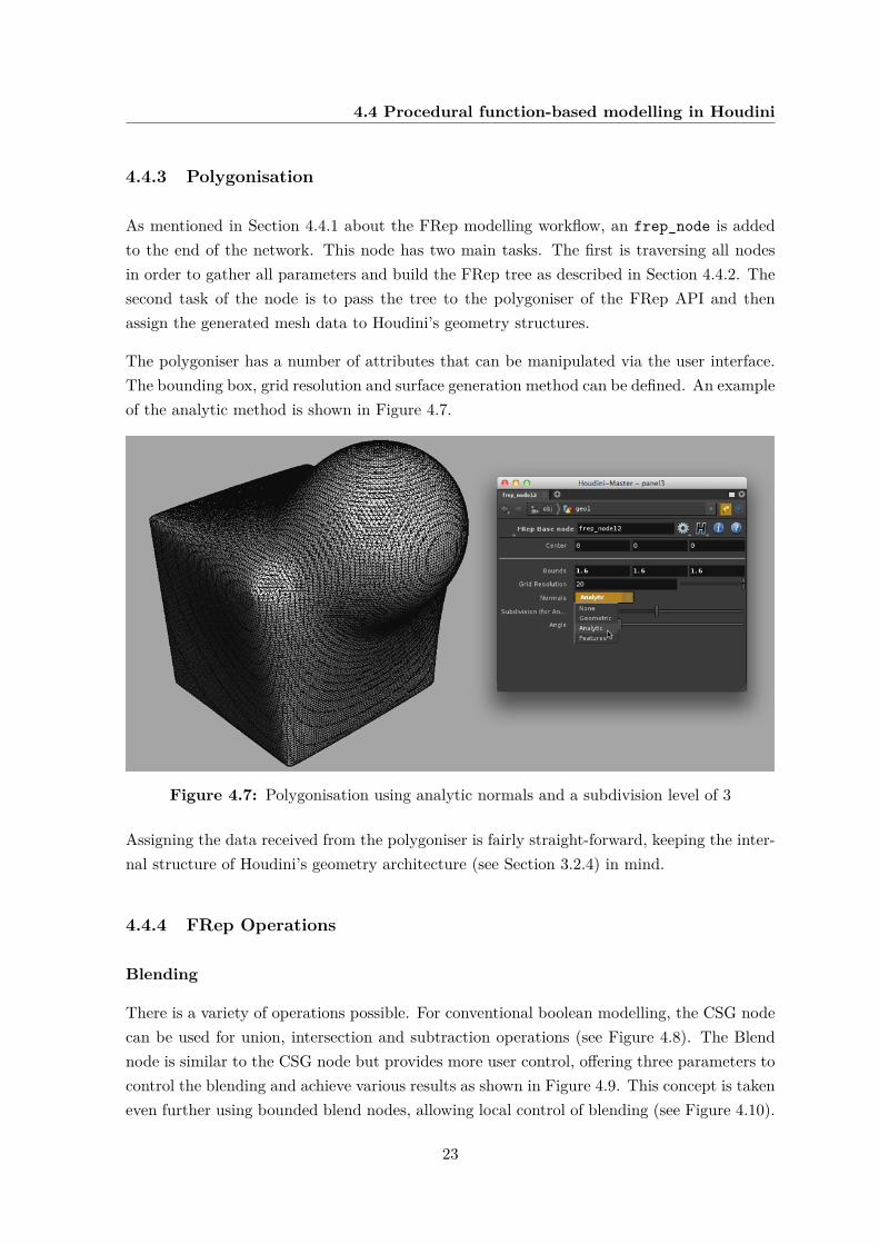
4.4.3 Polygonisation
As mentioned in Section 4.4.1 about the FRep modelling workflow, an frep_node is addedto the end of the network. This node has two main tasks. The first is traversing all nodesin order to gather all parameters and build the FRep tree as described in Section 4.4.2. Thesecond task of the node is to pass the tree to the polygoniser of the FRep API and thenassign the generated mesh data to Houdini’s geometry structures.
The polygoniser has a number of attributes that can be manipulated via the user interface.The bounding box, grid resolution and surface generation method can be defined. An exampleof the analytic method is shown in Figure 4.7.
Figure 4.7: Polygonisation using analytic normals and a subdivision level of 3
Assigning the data received from the polygoniser is fairly straight-forward, keeping the inter-nal structure of Houdini’s geometry architecture (see Section 3.2.4) in mind.
4.4.4 FRep Operations
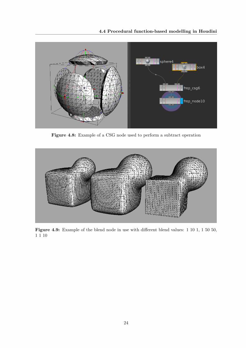
Blending
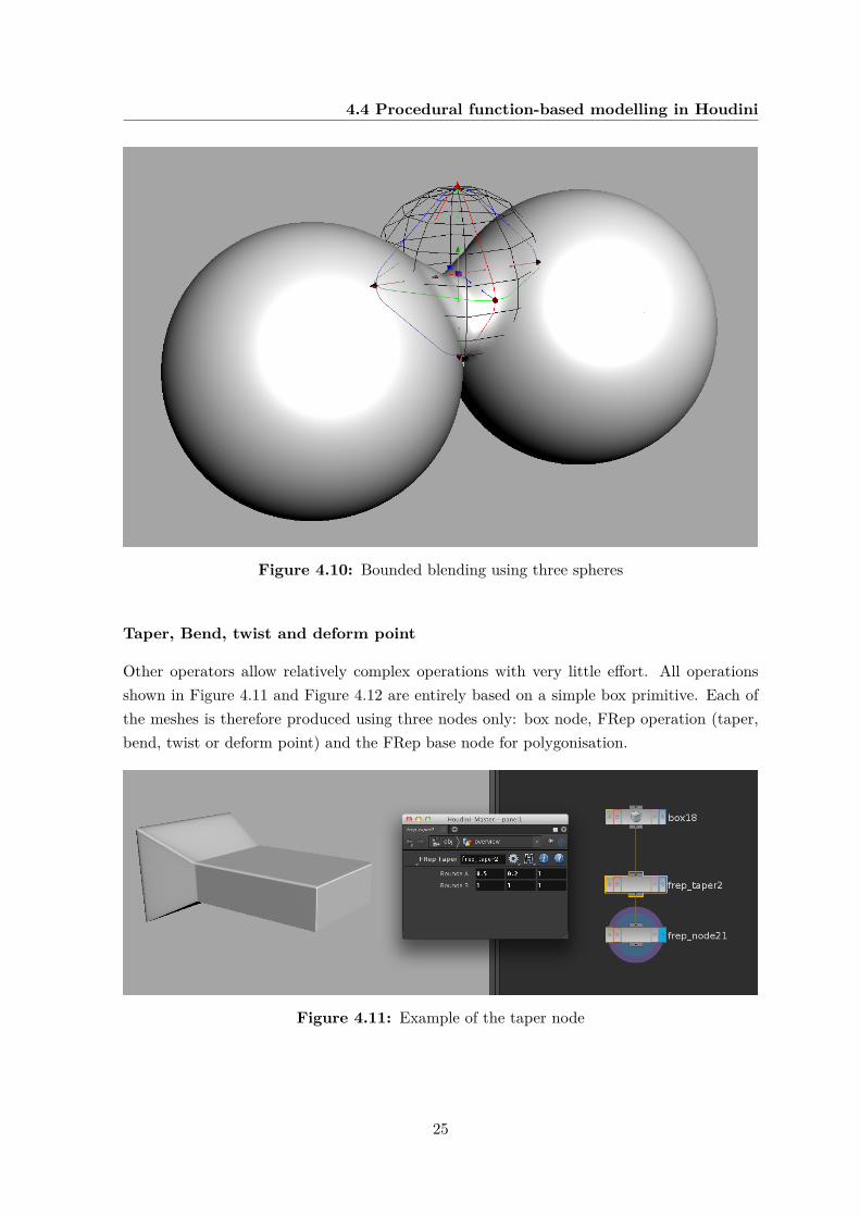
There is a variety of operations possible. For conventional boolean modelling, the CSG nodecan be used for union, intersection and subtraction operations (see Figure 4.8). The Blendnode is similar to the CSG node but provides more user control, offering three parameters tocontrol the blending and achieve various results as shown in Figure 4.9. This concept is takeneven further using bounded blend nodes, allowing local control of blending (see Figure 4.10).
23
4.4 Procedural function-based modelling in Houdini
Figure 4.8: Example of a CSG node used to perform a subtract operation
Figure 4.9: Example of the blend node in use with different blend values: 1 10 1, 1 50 50,1 1 10
24
4.4 Procedural function-based modelling in Houdini
Figure 4.10: Bounded blending using three spheres
Taper, Bend, twist and deform point
Other operators allow relatively complex operations with very little effort. All operationsshown in Figure 4.11 and Figure 4.12 are entirely based on a simple box primitive. Each ofthe meshes is therefore produced using three nodes only: box node, FRep operation (taper,bend, twist or deform point) and the FRep base node for polygonisation.
Figure 4.11: Example of the taper node
25
4.4 Procedural function-based modelling in Houdini
Figure 4.12: Examples of bend, twist and deform point operations
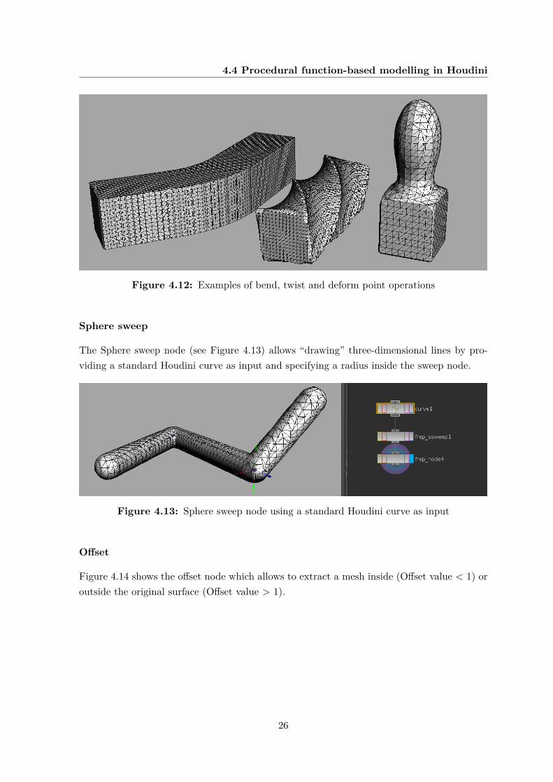
Sphere sweep
The Sphere sweep node (see Figure 4.13) allows “drawing” three-dimensional lines by pro-viding a standard Houdini curve as input and specifying a radius inside the sweep node.
Figure 4.13: Sphere sweep node using a standard Houdini curve as input
Offset
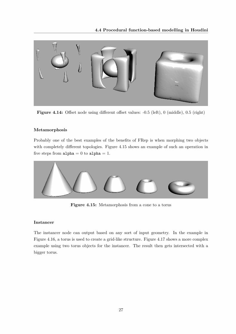
Figure 4.14 shows the offset node which allows to extract a mesh inside (Offset value < 1) oroutside the original surface (Offset value > 1).
26
4.4 Procedural function-based modelling in Houdini
Figure 4.14: Offset node using different offset values: -0.5 (left), 0 (middle), 0.5 (right)
Metamorphosis
Probably one of the best examples of the benefits of FRep is when morphing two objectswith completely different topologies. Figure 4.15 shows an example of such an operation infive steps from alpha = 0 to alpha = 1.
Figure 4.15: Metamorphosis from a cone to a torus
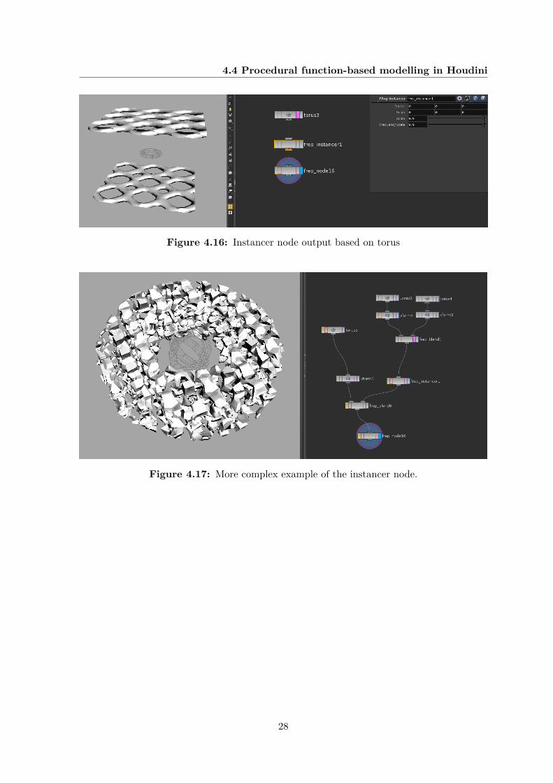
Instancer
The instancer node can output based on any sort of input geometry. In the example inFigure 4.16, a torus is used to create a grid-like structure. Figure 4.17 shows a more complexexample using two torus objects for the instancer. The result then gets intersected with abigger torus.
27
4.4 Procedural function-based modelling in Houdini
Figure 4.16: Instancer node output based on torus
Figure 4.17: More complex example of the instancer node.
28
Chapter 5
Results and analysis
Like traditional polygon modelling, FRep modelling offers the same vastness of possibilities.Virtually anything can be created, any attribute of an object can be controlled and changedover time. This chapter tries to provide an idea of what is possible by showing some examples,but also outlining some of the limitations of the current system.
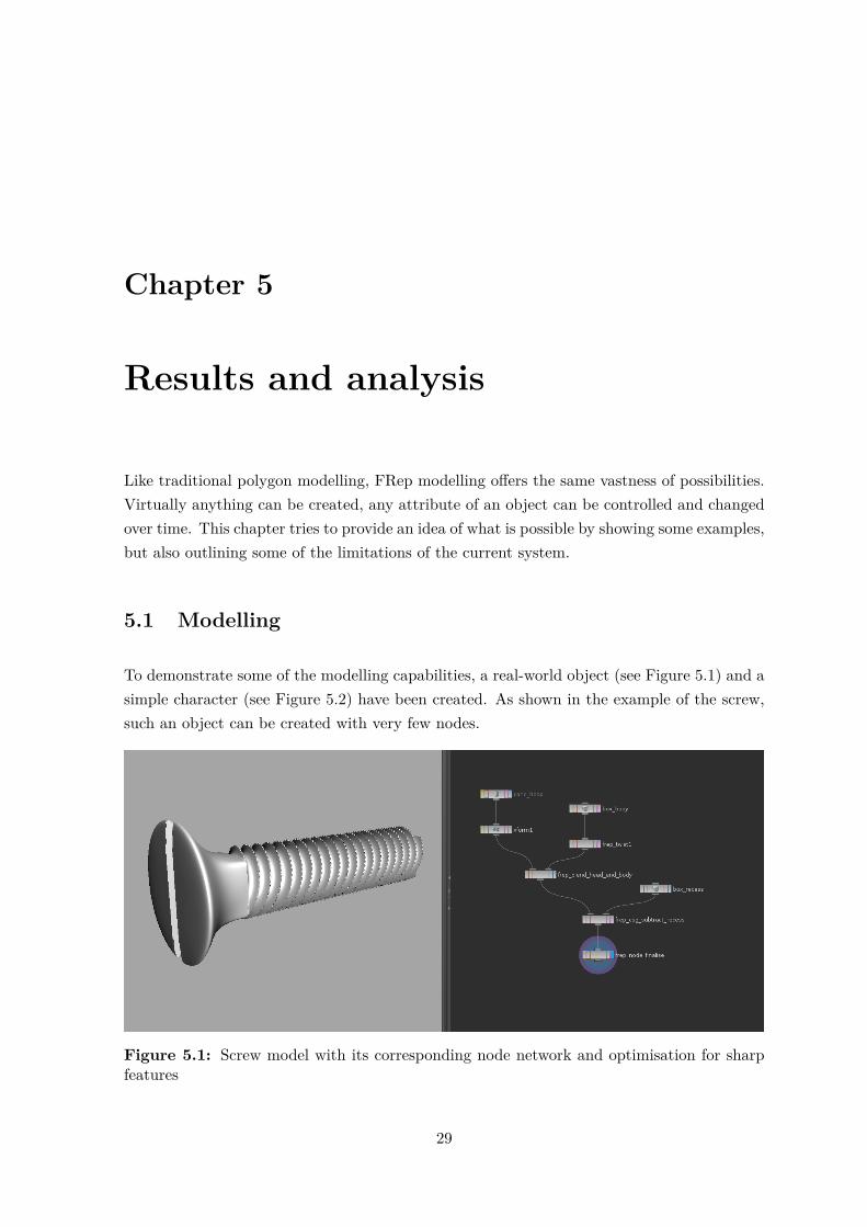
5.1 Modelling
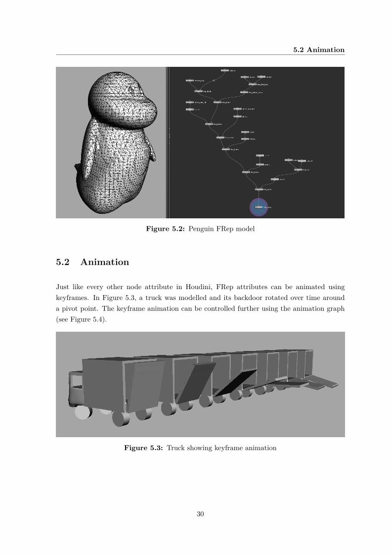
To demonstrate some of the modelling capabilities, a real-world object (see Figure 5.1) and asimple character (see Figure 5.2) have been created. As shown in the example of the screw,such an object can be created with very few nodes.
Figure 5.1: Screw model with its corresponding node network and optimisation for sharpfeatures
29
5.2 Animation
Figure 5.2: Penguin FRep model
5.2 Animation
Just like every other node attribute in Houdini, FRep attributes can be animated usingkeyframes. In Figure 5.3, a truck was modelled and its backdoor rotated over time arounda pivot point. The keyframe animation can be controlled further using the animation graph(see Figure 5.4).
Figure 5.3: Truck showing keyframe animation
30
5.3 Morphing
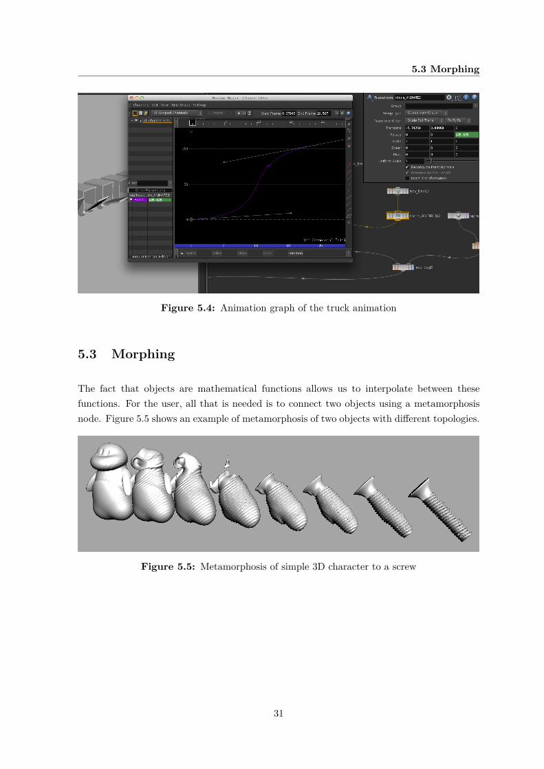
Figure 5.4: Animation graph of the truck animation
5.3 Morphing
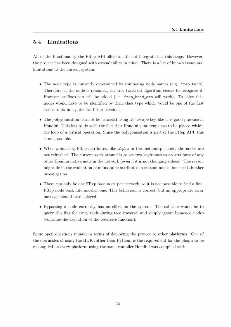
The fact that objects are mathematical functions allows us to interpolate between thesefunctions. For the user, all that is needed is to connect two objects using a metamorphosisnode. Figure 5.5 shows an example of metamorphosis of two objects with different topologies.
Figure 5.5: Metamorphosis of simple 3D character to a screw
31
5.4 Limitations
5.4 Limitations
All of the functionality the FRep API offers is still not integrated at this stage. However,the project has been designed with extendability in mind. There is a list of known issues andlimitations to the current system:
• The node type is currently determined by comparing node names (e.g. frep_bend).Therefore, if the node is renamed, the tree traversal algorithm ceases to recognise it.However, suffixes can still be added (i.e. frep_bend_arm will work). To solve this,nodes would have to be identified by their class type which would be one of the firstissues to fix in a potential future version.
• The polygonisation can not be canceled using the escape key like it is good practice inHoudini. This has to do with the fact that Houdini’s interrupt has to be placed withinthe loop of a critical operation. Since the polygonisation is part of the FRep API, thisis not possible.
• When animating FRep attributes, like alpha in the metamorph node, the nodes arenot refreshed. The current work around is to set two keyframes to an attribute of anyother Houdini native node in the network (even if it is not changing values). The reasonmight lie in the evaluation of animatable attributes in custom nodes, but needs furtherinvestigation.
• There can only be one FRep base node per network, so it is not possible to feed a finalFRep node back into another one. This behaviour is correct, but an appropriate errormessage should be displayed.
• Bypassing a node currently has no effect on the system. The solution would be toquery this flag for every node during tree traversal and simply ignore bypassed nodes(continue the execution of the recursive function).
Some open questions remain in terms of deploying the project to other platforms. One ofthe downsides of using the HDK rather than Python, is the requirement for the plugin to berecompiled on every platform using the same compiler Houdini was compiled with.
32
Chapter 6
Conclusion
Basing a project on an external library (which had to be ported first), while at the same timetackling a complex SDK like the Houdini Development Kit was certainly an ambitious goal. Inretrospect, the objective of bringing FRep modelling capabilities to Houdini while respectingexisting guidelines and UI paradigms, was achieved. Particularly the degree of integrationinto the Houdini environment is very promising for future projects and applications.
The FRep API offers a vast set of features. Some nodes and features could not be integratedgiven the short duration of this project. There is also a list of known issues and limitationsto the system, as discussed in Section 5.4. Choosing the HDK over Python was the rightdecision and, apart from having performance benefits, offering a clean and solid foundationfor future development.
6.1 Applications
The technology can have applications in industries like film and games, especially as comput-ers get faster and more accurate representations of the real-world are desired. Furthermore,being able to blend and morph objects regardless of topology is challenging using currentmethods.
Since FReps are resolution-independent, they are ideal for use in digital manufacturing and3D printing. Additional nodes could be developed to allow export from Houdini to variousfile formats like STL.
33
6.2 Future work
6.2 Future work
In addition to addressing known issues (see Section 5.4), there are various nodes in theFRep API that remain to be implemented. Other limitations are connected to the nature offunction-based modelling itself. For example, it can be very difficult for a user to imagine theinfluence of each of the attributes in a blend operation. Developing new tools and techniquesto allow more intuitive FRep modelling and teaching artists to use these appropriately isanother area for further research.
Houdini has its own iso surface node to polygonise implicit functions. It might be interestingto investigate potential performance benefits when integrating Houdini’s polygoniser into thecurrent system. On the other hand, optimisations to the polygonsier like the support forsharp features would go missing.
Performance is still an issue, especially as models become more complex and higher resolutionsare applied. To leverage multiple CPU cores or the GPU, additional efforts are needed, asshown with the CUDA integration in the Maya plugin (Kravtsov 2011).
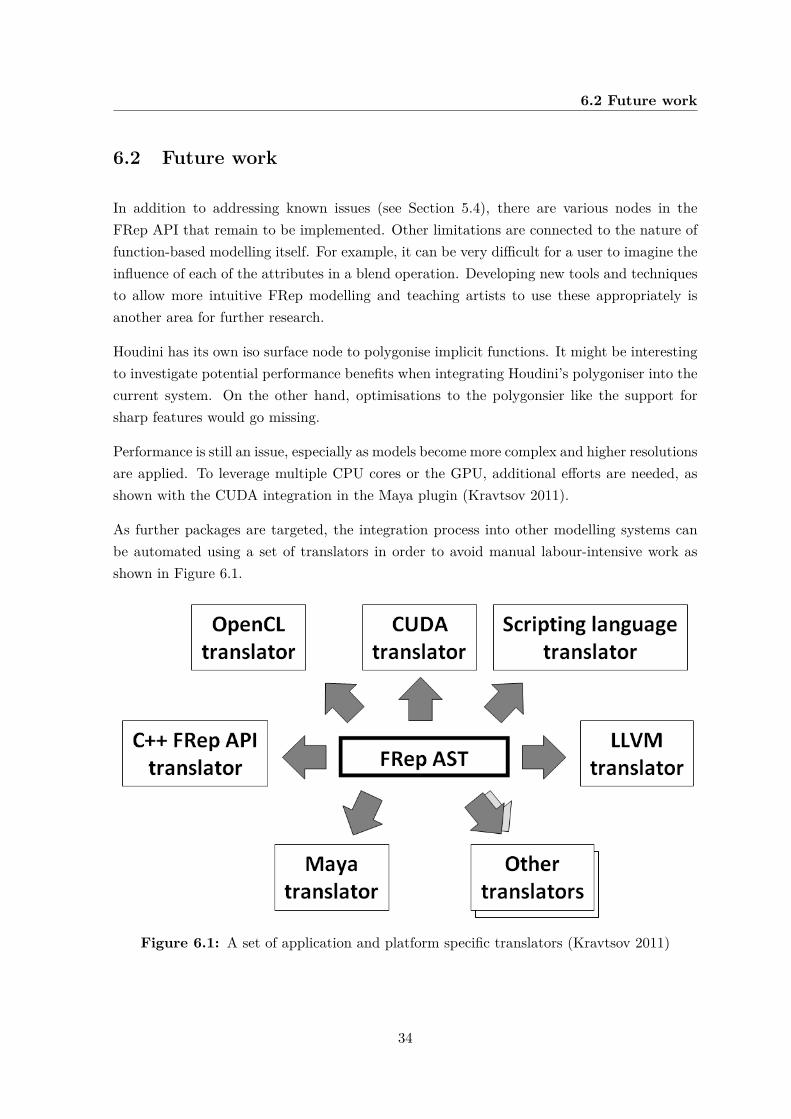
As further packages are targeted, the integration process into other modelling systems canbe automated using a set of translators in order to avoid manual labour-intensive work asshown in Figure 6.1.
Figure 6.1: A set of application and platform specific translators (Kravtsov 2011)
34
REFERENCES
References
Adzhiev, V., Pasko, A., and Sarkisov, A. (1996), Hyperjazz project: development ofgeometric modelling systems with inherent symbolic interactivity. In CSG 96 (Winchester,UK, 17-19 April 1996), Information Geometers, 183198.
Adzhiev, V., Cartwright, R., Fausett, E., Ossipov, A., Pasko, A., andSavchenko, V. (1999), Hyperfun project: a framework for collaborative multidimensionalf-rep modeling. Available from: http://hyperfun.org/HF_paper.pdf [Accessed 10 August2011].
Gamma, E., Helm, R., Johnson, R., and Vlissides, J. (1995), Design patterns: elementsof reusable object-oriented software.
Kravtsov, D. (2011), Hybrid modelling of time-variant heterogeneous objects. PhD Thesis.
Ohtake, Y., Belyaev, A., and Pasko, A. (2002), Dynamic mesh opti-mization for polygonized implicit surfaces with sharp features. Available from:http://hyperfun.org/TVC02obp.pdf [Accessed 5 August 2011].
Pasko, A. (2011), What is frep? Available from:http://hyperfun.org/wiki/doku.php?id=frep:what [Accessed 5 August 2011].
Pasko, A., Adzhiev, V., Sourin, A., and Savchenko, V. (1995), Function representa-tion in geometric modeling: concepts, implementation and applications. Available from:http://hyperfun.org/TVC95.pdf [Accessed 5 August 2011].
Pasko, G., Pasko, A., and Kunii, T. (2005), Bounded blending for function-based shapemodeling. Available from: http://www.hyperfun.org/BoundBlend_CGAprefinal.pdf [Ac-cessed 5 August 2011].
Schmidt, S. H. (2011), Hdk - houdini makefile for mac. Available from:http://www.subsites.org/484.0.html [Accessed 1 August 2011].
SideFX (2011)a, Houdini development kit – architectural overview. Available from:http://www.sidefx.com/docs/hdk11.0/hdk_opbasics_architecture.html [Accessed 1 Au-gust 2011].
SideFX (2011)b, Houdini development kit – geometry introduction. Availablefrom: http://www.sidefx.com/docs/hdk11.0/hdk_geometry_intro.html [Accessed 1 Au-gust 2011].
SideFX (2011)c, Extending the hou module using c++. Available from:http://www.sidefx.com/docs/houdini11.0/hom/extendingwithcpp [Accessed 3 August2011].
35