ProASICPLUS Starter Kit - microsemi.com
86
ProASIC PLUS Starter Kit User’s Guide & Tutorial
Transcript of ProASICPLUS Starter Kit - microsemi.com

ProASICPLUS Starter Kit
User’s Guide & Tutorial
ProASIC_UG.book Page i Wednesday, November 24, 2004 8:09 AM

ii
Actel Corporation, Mountain View, CA 94043© 2004 Actel Corporation. All rights reserved.
Printed in the United States of America
Part Number: 5020005-2
Release: November 2004
No part of this document may be copied or reproduced in any form or by any means without prior written consent of Actel.
Actel makes no warranties with respect to this documentation and disclaims any implied warranties of merchantability or fitness for a particular purpose. Infor-mation in this document is subject to change without notice. Actel assumes no responsibility for any errors that may appear in this document.This document contains confidential proprietary information that is not to be disclosed to any unauthorized person without prior written consent of Actel Cor-poration.TrademarksActel and the Actel logotype are registered trademarks of Actel Corporation.
Adobe and Acrobat Reader are registered trademarks of Adobe Systems, Inc.
Liberty is a licensed trademark of Synopsys Inc. This product uses SDC, a Pro-prietary format of Synopsys Inc.
Libero Integrated Design Environment is a trademark of Actel Corporation.
Mentor Graphics, Viewlogic, ViewDraw, MOTIVE, and ModelSim are regis-tered trademarks of Mentor Graphics, Inc.
Synplify and Synplicity are registered trademarks of Synplicity, Inc.
Verilog is a registered trademark of Open Verilog International.
WaveFormer Lite and SynaptiCAD are trademarks of SynaptiCAD, Inc.
Windows is a registered trademark and Windows NT is a trademark of Mi-crosoft Corporation in the U.S. and other countries.
All other products or brand names mentioned are trademarks or registered trade-marks of their respective holders.
ProASIC_UG.book Page ii Wednesday, November 24, 2004 8:09 AM

ProASIC PLUS Starter Kit User’s Guide iii
Table of Contents
Introduction . . . . . . . . . . . . . . . . . . . . . . . . . . . . . . . . . . . . 5Document Contents . . . . . . . . . . . . . . . . . . . . . . . . . . . . . . . 5
Document Assumptions . . . . . . . . . . . . . . . . . . . . . . . . . . . . . 5
1 Contents and System Requirements . . . . . . . . . . . . . . . . . . . . 7Starter Kit Contents . . . . . . . . . . . . . . . . . . . . . . . . . . . . . . . 7
2 Hardware Components . . . . . . . . . . . . . . . . . . . . . . . . . . . . . 9ProASICPLUS Evaluation Board . . . . . . . . . . . . . . . . . . . . . . . . 9
Power Supply . . . . . . . . . . . . . . . . . . . . . . . . . . . . . . . . . 10
Programming Headers. . . . . . . . . . . . . . . . . . . . . . . . . . . . . 10
Clock Circuits . . . . . . . . . . . . . . . . . . . . . . . . . . . . . . . . . 11
LED Device Connections . . . . . . . . . . . . . . . . . . . . . . . . . . . 11
Switches Device Connections . . . . . . . . . . . . . . . . . . . . . . . . . 12
3 Setup and Self Test . . . . . . . . . . . . . . . . . . . . . . . . . . . . . . 15Software Installation. . . . . . . . . . . . . . . . . . . . . . . . . . . . . . 15
Hardware Installation . . . . . . . . . . . . . . . . . . . . . . . . . . . . . 15
Testing the Evaluation Board . . . . . . . . . . . . . . . . . . . . . . . . . 15
Programming the Test file. . . . . . . . . . . . . . . . . . . . . . . . . . . 16
4 Actel VHDL APA Design Flow . . . . . . . . . . . . . . . . . . . . . 17Design Entry . . . . . . . . . . . . . . . . . . . . . . . . . . . . . . . . . 18
Design Implementation . . . . . . . . . . . . . . . . . . . . . . . . . . . . 19
Programming . . . . . . . . . . . . . . . . . . . . . . . . . . . . . . . . . 20
System Verification . . . . . . . . . . . . . . . . . . . . . . . . . . . . . . 20
5 Quick Start Tutorial . . . . . . . . . . . . . . . . . . . . . . . . . . . . . . 21Step 1 – Create a New Project. . . . . . . . . . . . . . . . . . . . . . . . . 21
Step 2 – Perform a Pre-synthesis Simulation . . . . . . . . . . . . . . . . . 25
ProASIC_UG.book Page iii Wednesday, November 24, 2004 8:09 AM

iv ProASIC PLUS Starter Kit User’s Guide
Step 3 – Synthesize the Design in Synplify . . . . . . . . . . . . . . . . . . 39
Step 4 – Perform a Post-Synthesis Simulation . . . . . . . . . . . . . . . . . 41
Step 5 – Implement the Design with Designer . . . . . . . . . . . . . . . . 42
Step 6 – Perform a Timing Simulation with Back-Annotated Timing . . . . 49
Step 7 – Generate the Programming File . . . . . . . . . . . . . . . . . . . 50
Step 8 – Program the Device . . . . . . . . . . . . . . . . . . . . . . . . . . 51
A Board Connections . . . . . . . . . . . . . . . . . . . . . . . . . . . . . . .65
B Board Schematics . . . . . . . . . . . . . . . . . . . . . . . . . . . . . . .77Top-Level View . . . . . . . . . . . . . . . . . . . . . . . . . . . . . . . . 77
Bottom-Level View . . . . . . . . . . . . . . . . . . . . . . . . . . . . . . 78
C Product Support . . . . . . . . . . . . . . . . . . . . . . . . . . . . . . . .81Actel U.S. Toll-Free Line . . . . . . . . . . . . . . . . . . . . . . . . . . . 81
Customer Service . . . . . . . . . . . . . . . . . . . . . . . . . . . . . . . . 81
Customer Applications Center . . . . . . . . . . . . . . . . . . . . . . . . . 81
Guru Automated Technical Support . . . . . . . . . . . . . . . . . . . . . . 81
Web Site . . . . . . . . . . . . . . . . . . . . . . . . . . . . . . . . . . . . 82
FTP Site . . . . . . . . . . . . . . . . . . . . . . . . . . . . . . . . . . . . 82
Contacting the Customer Applications Center . . . . . . . . . . . . . . . . 82
Worldwide Sales Offices . . . . . . . . . . . . . . . . . . . . . . . . . . . . 83
Index . . . . . . . . . . . . . . . . . . . . . . . . . . . . . . . . . . . . . . . .85
ProASIC_UG.book Page iv Wednesday, November 24, 2004 8:09 AM

5
Introduction
Thank you for purchasing Actel’s ProASICPLUS Starter Kit.
This guide provides the information required to easily evaluate the ProASICPLUS devices. This is the first release of the Starter Kit User’s Guide. The most up-to-date version of this guide is available at:
http://www.actel.com/techdocs/manuals/default.asp.
Document ContentsChapter 1 - Contents and System Requirements describes the contents of the ProASICPLUS Starter Kit.
Chapter 2 - Hardware Components describes the components of the ProASICPLUS Evaluation Board.
Chapter 3 - Setup and Self Test describes how to setup the ProASICPLUS Evaluation Board and how to perform a self test.
Chapter 4- Actel VHDL APA Design Flow introduces the design flow for VHDL using the Actel Libero™ Integrated Design Environment (IDE) suite.
Chapter 5- Quick Start Tutorial contains a step-by-step tutorial.
Appendix A - Board Connections provides a table listing the board connections.
Appendix B - Board Schematics provides illustrations of the ProASICPLUS Evaluation Board.
Appendix C - Product Support describes Actel’s support services.
Document AssumptionsThis user’s guide assumes:
• You intend to use Actel’s Libero IDE software.
• You have installed and are familiar with Actel’s Libero IDE 2.3 SP 2 software.
• You are familiar with the VHDL hardware description language.
• You are familiar with PCs and Windows operating systems.
ProASIC_UG.book Page 5 Wednesday, November 24, 2004 8:09 AM

Document Assumptions
6 ProASICPLUS Starter Kit User’s Guide
ProASIC_UG.book Page 6 Wednesday, November 24, 2004 8:09 AM

7
1Contents and System Requirements
This chapter details the contents of the ProASICPLUS Starter Kit and lists the power supply and software system requirements.
Starter Kit ContentsThe starter kit includes:
• Evaluation board - APA-EVAL-BRD300-SA
• Libero IDE Gold
• FlashPro Lite
• The ProASICPLUS Starter Kit User’s Guide & Tutorial
• Customer Letter
• CD with design examples
• Switching brick power supply, part number DTS090220U-P5P-SZ from CUI INC
For the CD contents, review the ReadMe.doc file at the top level of the CD.
ProASIC_UG.book Page 7 Wednesday, November 24, 2004 8:09 AM

Starter Kit Contents
8 ProASICPLUS Starter Kit User’s Guide
ProASIC_UG.book Page 8 Wednesday, November 24, 2004 8:09 AM

9
2Hardware Components
This chapter describes the hardware components of the ProASICPLUS Evaluation board.
ProASICPLUS Evaluation BoardFigure 2-1 illustrates a top-level view of the ProASICPLUS Evaluation board.
Figure 2-1. ProASICPLUS Evaluation Board: Top-Level View
ProASIC_UG.book Page 9 Wednesday, November 24, 2004 8:09 AM

Power Supply
10 ProASIC PLUS Starter Kit User’s Guide
The ProASICPLUS evaluation board consists of:
• Wall mount power supply connector, with switch and LED indicator
• Jumper to select between 2.5V and 3.3V I/O voltages
• Small program header (compatible with both FlashPro/FlashPro Lite and Silicon Sculptor)
• 40MHz oscillator and manual clock option
• Eight LEDs (driven by outputs from the device)
• Jumpers (allow disconnection of all external circuitry from the FPGA)
• Four switches (provide input to the device)
For further information, refer to the following appendices:
Appendix A – Board Connections
Appendix B – Board Schematics
Power SupplyTo use the ProASICPLUS Evaluation board with a wall mount power supply, use the switching brick power supply that is provided with the kit. The power supply is controlled by an On/Off switch. An LED DS9 indicates the presence of a working wall mount supply.
• Use JP1 to select either 3.3V or 2.5V for the Device I/O Voltage.
• JP2 connects AGND to GND for the use of the PLL.
• JP3 connects AVDD to VDD for the use of the PLL.
Note: Alternatively, use the five pin header next to the power supply connection to drive power to the board from a laboratory supply.
Programming HeadersA small form programming header, which is suitable for use with both the FlashPro/FlashPro Lite and Silicon Sculptor II, is supplied with the board. The footprint for the large programming header is on the board, but has not been populated.
When using FlashPro/FlashPro Lite, use the STAPL(.STP) file to program the device. Silicon Explorer II can be used for both bitstream (.BIT) or STAPL (.STP) files. However, the ISP programming adapter module SMPA-ISP-ACTEL-2-KIT is required to use Silicon Sculptor II with the ProASICPLUS Evaluation board.
ProASIC_UG.book Page 10 Wednesday, November 24, 2004 8:09 AM

40MHz Oscillator Clock Circuits
ProASIC PLUS Starter Kit User’s Guide 11
Clock Circuits The ProASICPLUS Evaluation board has two clock circuits, a 40MHz oscillator and a manual clock.
40MHz Oscillator The 40MHz oscillator on the board is connected to JP4. JP4 connects the clock to pin 24 of the devices. Pin 24 is a global input pin. To use pin 24 for a different clock signal, disconnect JP4.
To use a different Clock Frequency, purchase the Crystal from Epson programmed to a variety of frequencies. The SG-8002JC40.000M-PCC from Epson is also available through Digikey.
Manual ClockWhen activated, the manual clock button (PB1) lights DS10, the pulse generated LED, and generates a pulse. This is connected to JP17. JP17 connects to pin 128 of the device. Pin 128 is a global input pin.
To use pin 128 for a different clock signal, disconnect JP17.
LED Device ConnectionsEight LEDs are connected to the device via jumpers. If the jumpers are in place, the device I/O can drive the LEDs. The LEDs change based on the following output:
• A ‘1’ on the output of the device lights the LED.
• A ‘0’ on the output of the device switches off the LED.
• An unprogrammed or tristated output may show a faintly lit LED.
Table 2-1 lists the LED/device connections.
To use the device I/O for other purposes, remove the jumpers.
Table 2-1. LED Device Connections
LED Device Connection
DS1 Pin 87
DS2 Pin 90
DS3 Pin 91
ProASIC_UG.book Page 11 Wednesday, November 24, 2004 8:09 AM

Switches Device Connections Manual Clock
12 ProASIC PLUS Starter Kit User’s Guide
Figure 2-2 illustrates the location of the LED/device connections on the ProASICPLUS evaluation board.
Switches Device ConnectionsFour switches are connected to the device via jumpers. If the jumpers are in place, the device I/O can be driven by the switches listed in Table 2-2 .• Pressing a switch drives a 1 into the device. The 1 continues to drive while the switch is in place.
• Releasing a switch drives a zero into the device.
Table 2-2 lists the switch/device connections.
DS4 Pin 92
DS5 Pin 93
DS6 Pin 94
DS7 Pin 95
DS8 Pin 96
Figure 2-2. LED Device Connections
Table 2-1. LED Device Connections
LED Device Connection
ProASIC_UG.book Page 12 Wednesday, November 24, 2004 8:09 AM

Manual Clock Switches Device Connections
ProASIC PLUS Starter Kit User’s Guide 13
To use the device I/O for other purposes, remove the jumpers.
Figure 2-3 illustrates the switch device connections.
Table 2-2. Switch Device Connections
Switch Device Connections
SW1 Pin 55
SW2 Pin 63
SW3 Pin 69
SW4 Pin 79
Figure 2-3. Switch Device Connections
ProASIC_UG.book Page 13 Wednesday, November 24, 2004 8:09 AM

Switches Device Connections Manual Clock
14 ProASIC PLUS Starter Kit User’s Guide
ProASIC_UG.book Page 14 Wednesday, November 24, 2004 8:09 AM

15
3Setup and Self Test
This chapter outlines how to set up and test the ProASICPLUS Evaluation Board.
Software InstallationThe ProASICPLUS Starter Kit includes the Libero™ Integrated Design Environment (IDE) software (version 2.3 SP2). For Libero IDE software installation instructions, refer to the Actel Installation and Licensing Guide at:
http://www.actel.com/documents/install.pdf.
Hardware InstallationFlashPro Lite is required to use the ProASICPLUS Starter Kit. For software and hardware installation instructions refer the FlashPro User’s Guide at:
http://www.actel.com/documents/flashproUG.pdf.
Testing the Evaluation BoardIf the evaluation board is shipped directly from Actel, it contains a test program that determines if the board works properly.
To test the evaluation board:
1. Connect the power supply to the board.
2. Turn on the ON/OFF switch.
3. Perform the actions described in Table 3-1. For locations of the switches mentioned in Table 3-1, refer to Figure 2-1 on page 9.
Table 3-1. Evaluation Board
Action Result Pass/Fail
Press PB1 multiple times, but not too quickly
Count sequence should be visible on the LEDs
Pass
Press and hold SW1 All LEDs are unlit Pass
ProASIC_UG.book Page 15 Wednesday, November 24, 2004 8:09 AM

Programming the Test file
16 ProASICPLUS Starter Kit User’s Guide
Programming the Test fileTo retest the evaluation board at any time, use the test program to reprogram the board. Use the test.stp STAPL file or the test.bit bitstream file. These files are included on the Starter Kit CD.
This design is currently implemented for the APA075 and APA300 package devices. For a device of a different size, it is possible to recompile the design into other device sizes. For information about retargeting the device, refer to the Designer User’s Guide at http://www.actel.com/documents/designerUG.pdf. The design files are available under actelprj/eval in the Starter Kit CD.
For instructions on programming the device using FlashPro Lite, refer to the FlashPro User’s Guide at:
http://www.actel.com/documents/flashproUG.pdf.
Press and hold SW2 All LEDs are lit Pass
Press and hold SW3Count sequence runs while you hold the switch
Pass
Press and hold SW4LED is lit/unlit alternately in a 10101010 pattern
Pass
Press any two switches simultaneously
Creates a 00110011 pattern Pass
Table 3-1. Evaluation Board
Action Result Pass/Fail
ProASIC_UG.book Page 16 Wednesday, November 24, 2004 8:09 AM

17
4Actel VHDL APA Design Flow
This chapter introduces the design flow for VHDL using the Actel Libero IDE software suite. This chapter also briefly describes how to use the software tools and provides information about the sample design. Figure 4-1 shows the VHDL-based design flow.
Figure 4-1. VHDL-Based Design Flow
CLAM Designer
ActelDevice
Design Creation/Verification
Design Implementation
SystemVerification
Programming
Silicon Sculptor
SDFFile
StructuralHDL
Netlist
EDIFNetlist
SynthesisLibrary
Design Synthesis &Optimization
Compile LayoutFuse
x
PinEdit ChipEdit Timer
BackAnnotate
User Tools
Power
ACTgenMacro Builder
ProgrammingFile (stp/bit)
Bitstreamor
0101
HDL Editor
UserTestbench
Timing Simulation
ModelSimSimulator
Functional Simulation
WaveFormer LiteTestbench
Stimulus Generation
SynplifySynthesis
SmartNetlistViewer
Flash Pro
ProASIC_UG.book Page 17 Wednesday, November 24, 2004 8:09 AM

Design Entry
18 ProASICPLUS Starter Kit User’s Guide
The Libero IDE design flow has four main components:
• Design Entry
• Design Implementation
• Programming
• System Verification
Design EntryDesign entry consists of capturing a schematic representation of the design and performing functional simulations with a test bench.
Design Capture
For schematic capture, Libero uses ViewDraw for Actel, which includes a schematic editor. The schematic editor provides a graphical entry method to capture designs. ViewDraw for Actel is the Libero integrated schematic entry vehicle, supporting mixed mode entry in which HDL blocks and schematic symbols can be mixed.
The ViewDraw wir file is automatically created after using the Save + Check command in ViewDraw. This file is used to create the structural HDL netlist.
For more information on using ViewDraw for Actel, refer to the Libero User’s Guide at http://www.actel.com/documents/liberoUG.pdf.
Adding ACTgen Macros
Use the ACTgen Macro Builder to instantly create customized macros and then use ViewDraw to add these macros to a schematic. Alternatively, add the ACTgen Macros in the HDL file.
Creating and Adding Symbols for HDL Files
Schematic users can encapsulate a HDL block into a block symbol.
To create a symbol:
1. Right-click the block in the Design Hierarchy window of Libero IDE.
2. Click Create Symbol. Libero IDE generates a symbol for the selected HDL block.
The macro is accessible from the components list in ViewDraw for Actel.
Test Bench Generation
It is necessary to create a test bench and associate it with a project in order to run a simulation. WaveFormer Lite from SynaptiCAD is the Libero IDE integrated test bench generator.
ProASIC_UG.book Page 18 Wednesday, November 24, 2004 8:09 AM

Design Implementation
ProASICPLUS Starter Kit User’s Guide
WaveFormer Lite fits perfectly into the Libero design environment, automatically extracting signal information from HDL design files, and producing HDL test bench code that can be used with any standard VHDL or Verilog simulator.
WaveFormer Lite generates VHDL and Verilog test benches from drawn waveforms.
Pre-Synthesis Simulation
Functional simulation verifies that the logic of a design is functionally correct. Simulation is performed using the Libero integrated simulator, ModelSim for Actel. ModelSim for Actel is a custom edition of ModelSimPE that is integrated into the Libero design environment. ModelSim for Actel is an OEM edition of Model Technology Incorporated’s (MTI) tools. ModelSim for Actel supports VHDL or Verilog, but it can only simulate one language at a time. It only works with Actel libraries and is supported by Actel.
Synthesis & Netlist Generation
After entering the design source, synthesize it to generate a netlist. Synthesis transforms the behavioral HDL source into a gate-level netlist and optimizes the design for a target technology.
For more detailed information on the above topics, refer to the Libero User’s Guide at http://www.actel.com/documents/liberoUG.pdf.
Design ImplementationDuring design implementation, Actel’s Designer places-and-routes the design.
Place-and-Route
Start Designer from Libero IDE to place-and-route the design.
Timing Simulation
Perform timing simulation on the design after place-and-route in Designer. Timing simulation requires information extracted and back-annotated from Designer.
ProASIC_UG.book Page 19 Wednesday, November 24, 2004 8:09 AM

Programming
20 ProASICPLUS Starter Kit User’s Guide
Optional Tools
The tools listed in Table 4-1 provide optional functions that are not required in a basic design. Use these tools to perform static timing analysis, power analysis, customize I/O placements and attributes, and view the netlist. After place-and-route, perform the post-layout (timing) simulation.
For more information on the tools described in the above section, refer to the Designer User’s Guide at http://www.actel.com/documents/designerUG.pdf.
ProgrammingProgram the device with programming software and hardware from Actel or a supported 3rd party programming system. Refer to the Designer User’s Guide, Silicon Sculptor User’s Guide, and FlashPro User’s Guide for information about programming an Actel device.
These guides can be found at:
http://www.actel.com/techdocs/manuals/default.asp.
System VerificationUse the CLAM diagnostic tool to perform system verification on a programmed device. Refer to Technical Data For CLAM® System for Actel FPGA Devices for information about using CLAM. This guide can be found at:
http://www.actel.com/documents/CLAMActel.pdf.
Table 4-1. Designer’s User Tools
Designer User Tools User Tool Function
Timer Static timing analysis
SmartPower Power analysis
ChipEditCustomize I/O and logic macro placements
PinEdit Customize I/O placements and attributes
Netlist ViewerView your netlist and trace paths
ProASIC_UG.book Page 20 Wednesday, November 24, 2004 8:09 AM

21
5Quick Start Tutorial
This tutorial illustrates a simple basic VHDL design for an APA Evaluation Board. The design is targeted at the Actel ProASICPLUS family. To show the design in its simplest form, a simple andgate design is created in Actel’s Libero IDE 2.3 SP 2. The steps involved are:
Step 1 – Create a New Project
Step 2 – Perform a Pre-synthesis Simulation
Step 3 – Synthesize the Design in Synplify
Step 4 – Perform a Post-Synthesis Simulation
Step 5 – Implement the Design with Designer
Step 6 – Perform a Timing Simulation with Back-Annotated Timing
Step 7 – Generate the Programming File
Step 8 – Program the Device
Step 1 – Create a New ProjectThis step uses the Libero IDE HDL Editor to enter an Actel VHDL design.
To create the VHDL project:
1. Start Libero IDE by double-clicking the Actel Libero IDE icon on the desktop.
2. From the File menu, select New Project. The New Project dialog box is displayed, as shown in Figure 5-1.
ProASIC_UG.book Page 21 Wednesday, November 24, 2004 8:09 AM

Step 1 – Create a New Project
22 ProASICPLUS Starter Kit User’s Guide
.
Figure 5-1. New Project Dialog Box
3. Enter example in the Project Name field.
4. In the Project Location field, click Browse to navigate to C:\Actelprj.
5. Select PA from the Family drop-down list.
6. Check the VHDL radio button in the HDL field.
7. Click OK. The project “example” is created and opened in the Libero IDE.
8. From the File menu, click New. This opens the New dialog box, as shown in Figure 5-2.
ProASIC_UG.book Page 22 Wednesday, November 24, 2004 8:09 AM
Step 1 – Create a New Project
ProASICPLUS Starter Kit User’s Guide 23
Figure 5-2. New File Dialog Box
9. Select VHDL Entity in the File Type field, enter andgate in the Name field and click OK. The HDL Editor opens.
10. Enter the following VHDL file, or if this document is open in an electronic form, cut and paste it from this document.
ProASIC_UG.book Page 23 Wednesday, November 24, 2004 8:09 AM

Step 1 – Create a New Project
24 ProASICPLUS Starter Kit User’s Guide
-- AND Gate Tutorial for APA Evaluation BoardLIBRARY ieee;USE iee.std_logic_1164. ALL;
ENTITY andgate isport (A, B : in std_logic;-- Data InputsOUTPUT : out std_logic); -- Output= A AND Bend andgate;
architecture behaviour of andgate is
begin
OUTPUT <= A AND B;
end behaviour;
11. From the File menu, click Save. The design file “andgate” will now appear under the Design Hierarchy tab in Libero IDE as shown in Figure 5-3. The file name “andgate.vhd’ is listed under HDL files in the File Manager tab in the Libero IDE, as shown in Figure 5-4.
Figure 5-3. Design Hierarchy Tab
ProASIC_UG.book Page 24 Wednesday, November 24, 2004 8:09 AM

Step 2 – Perform a Pre-synthesis Simulation
ProASICPLUS Starter Kit User’s Guide 25
Figure 5-4. File Manager Tab
12. Click the File Manager tab.
13. Right-click on andgate.vhd and run “check HDL”. This checks the syntax of the andgate.vhd file. Before moving to the next section, please modify the code if any errors are visible.
Step 2 – Perform a Pre-synthesis SimulationThe next step is simulating the RTL description of the design. First, use WaveFormer Lite to create a stimulus for the design and then generate a test bench for the design.
Creating Stimulus Using WaveFormer Lite
WaveFormer Lite generates VHDL test benches from drawn waveforms. There are three basic steps for creating test benches using WaveFormer Lite and the Actel Libero IDE software:
1. Import Signal Information
2. Drawing Waveforms
3. Export the Test Bench
ProASIC_UG.book Page 25 Wednesday, November 24, 2004 8:09 AM

Step 2 – Perform a Pre-synthesis Simulation Import Signal Information
26 ProASICPLUS Starter Kit User’s Guide
Import Signal InformationTo launch WaveFormer Lite and import signal information into it:
1. Double-click the WaveForm Lite icon in the Libero IDE, or right-click the andgate file in the Design Hierarchy tab and select Create Stimulus. WaveFormer Lite launches, with the port signals appearing in the Diagram window, as shown in Figure 5-5.
Figure 5-5. WaveFormer Lite Timing Diagram Window
ProASIC_UG.book Page 26 Wednesday, November 24, 2004 8:09 AM

Drawing Waveforms Step 2 – Perform a Pre-synthesis Simulation
ProASICPLUS Starter Kit User’s Guide 27
The andgate design contains the following signals:
• A Input signal
• B Input signal
• OUTPUT Output Signal
Drawing WaveformsTo draw a Waveform:
The state buttons are the buttons with the waveforms drawn on their face: HIGH, LOW, TRIstate, VALid, INValid, WHI weak high, and WLO weak low, as shown in Figure 5-6.
Figure 5-6. State Buttons
When a state button is activated, it is pushed in and colored red. The active state is the type of waveform that is drawn next. To activate a state button, click on it.
The state buttons automatically toggle between the two most recently activated states. The state with the small red “T” above the name will be the toggle state. The initial activated state is HIGH and the initial toggle state is LOW.
Signal edges are automatically aligned to the closest edge grid when signals are drawn using the mouse. Control the edge grid from the Options > Grid Settings menu item.
1. Select the High state and place the mouse cursor inside the Diagram window at the same vertical row as the signal name.
2. Click the left mouse button. This draws a waveform from the end of the signal to the mouse cursor. The red state button on the button bar determines the type of waveform drawn. The cursor shape also mirrors the red state button.
3. Move the mouse to the right and click again to draw another segment.
To copy waveforms:
It is possible to copy and paste sections of waveforms onto (overwrite) or into (insert) any signal in the diagram. To copy and paste waveform sections:
1. Select the names of the required signals. If no signals are selected, the Block Copy command selects all the signals in the diagram.
ProASIC_UG.book Page 27 Wednesday, November 24, 2004 8:09 AM

Step 2 – Perform a Pre-synthesis Simulation Drawing Waveforms
28 ProASICPLUS Starter Kit User’s Guide
2. Select the Edit > Block Copy Waveforms menu option. This opens the Block Copy Waveforms dialog box (Figure 5-7) with the selected signals displayed in the Change Waveform Destination list box.
Figure 5-7. Block Copy Waveforms Dialog Box
ProASIC_UG.book Page 28 Wednesday, November 24, 2004 8:09 AM

Export the Test Bench Step 2 – Perform a Pre-synthesis Simulation
ProASICPLUS Starter Kit User’s Guide 29
3. In the dialog, enter the values that define the copy and paste.
Select either Time or Clock cycle for the base units of the dialog. Remember:
• When copying only signals (no clocks), time is the default base unit of the dialog.
• When copying part of a clock, it is best to choose a clock cycles base unit and choose the copied clock as the reference clock.
• If time is selected when copying clocks, the (end_time - start_time) must equal an integral number of clock periods, and the place_at time must be at the same clock period offset as the start_time.
• Start and End define the times of the block copy.
• Place At is the time at which the block will be pasted.
• The Insert and Overwrite radio buttons determine whether the paste block is inserted into the existing waveforms or overwrites those waveforms.
• The list box at the bottom of the dialog determines which signal the copied waveforms will be pasted into.
To change this mapping:
• Select a line in the list box.
This places the destination signal in the drop-down list box on top of the list box.
• Select another signal from the drop-down list box.
Each destination signal can be used only once per copy.
• Click OK to complete the copy and paste operation.
Export the Test BenchIn this step a stimulus file is created for the design and a test bench is generated using WaveFormer Lite. After exporting the testbench, perform a pre-synthesis simulation using ModelSim.
To Create a Stimulus File and Generate a VHDL Testbench:
In this step, a design stimulus file is created using WaveFormer Lite. Following the instructions in the previous sections, define values for the A input signal (A), the B input signal (B), and the output signal (OUTPUT).
ProASIC_UG.book Page 29 Wednesday, November 24, 2004 8:09 AM

Step 2 – Perform a Pre-synthesis Simulation Export the Test Bench
30 ProASICPLUS Starter Kit User’s Guide
1. Following the instructions on the previous pages, create waveforms for A and B, as described below:
This creates the waveform shown in Figure 5-8.
Table 5-1. Wave Forms for A and B
A – low 0nS – 100 ns
high 100 nS – 1 us
B – low 0nS – 300 ns
high 300 nS – 330 ns
low 330 nS – 1 us
ProASIC_UG.book Page 30 Wednesday, November 24, 2004 8:09 AM

Export the Test Bench Step 2 – Perform a Pre-synthesis Simulation
ProASICPLUS Starter Kit User’s Guide 31
Figure 5-8. WaveForm Timing Diagram
2. After successfully creating the waveforms, select Save As from the File menu. In the Save As dialog box, enter andgate_stim.btim as the file name and click Save.
3. After saving the timing diagram file, select Export Timing Diagram As from the Export menu.
4. Select “VHDL Wait with Top Level Test Bench” in Files of Type and enter andgate_stim.vhd for the file name, as shown in Figure 5-9.
ProASIC_UG.book Page 31 Wednesday, November 24, 2004 8:09 AM

Step 2 – Perform a Pre-synthesis Simulation Export the Test Bench
32 ProASICPLUS Starter Kit User’s Guide
Figure 5-9. andgate_stim.vhd
The WaveFormer Lite Report window displays the VHDL testbench with a component declaration and instantiation inside.
5. Exit WaveFormer Lite (File > Exit). The Libero IDE File Manager tab displays the stimulus files.
The design is ready to simulate under ModelSim.
To create a testbench using HDL editor:
Alternatively, create a testbench using the HDL editor. To create a stimulus file with the HDL Editor:
1. From the File menu, select New. This opens the New File dialog box.
2. Select Stimulus HDL file from the File Type list, enter andgate_stim for the name, and click OK. The file opens in the HDL Editor.
3. Create the VHDL testbench and save it.
Pre-Synthesis Simulation
Once the test bench is generated, use ModelSim to perform a pre-synthesis simulation.
To perform a pre-synthesis simulation:
1. Select a stimulus file. Right-click andgate in the Libero IDE Design Hierarchy tab and select “Select a Stimulus File”, as shown in Figure 5-10.
ProASIC_UG.book Page 32 Wednesday, November 24, 2004 8:09 AM

Export the Test Bench Step 2 – Perform a Pre-synthesis Simulation
ProASICPLUS Starter Kit User’s Guide 33
Figure 5-10. Selecting a Stimulus File
The Select Stimulus dialog box shown in Figure 5-11 appears.
ProASIC_UG.book Page 33 Wednesday, November 24, 2004 8:09 AM

Step 2 – Perform a Pre-synthesis Simulation Export the Test Bench
34 ProASICPLUS Starter Kit User’s Guide
Figure 5-11. Select Stimulus Dialog Box
2. Select andgate_stim.vhd in the Project List box and click Add to add the file to the Associated Files list.
3. Click OK. A check mark appears next to Waveformer Lite in the Process window, as shown in Figure 5-12.
ProASIC_UG.book Page 34 Wednesday, November 24, 2004 8:09 AM
Export the Test Bench Step 2 – Perform a Pre-synthesis Simulation
ProASICPLUS Starter Kit User’s Guide 35
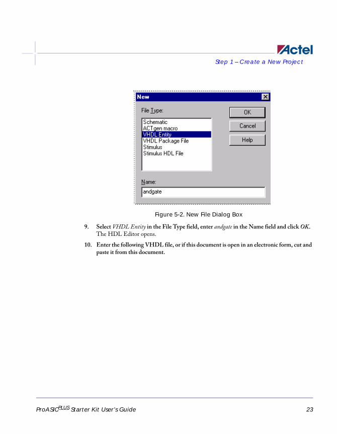
Figure 5-12. Check Mark in Waveformer Lite
4. Double-click the ModelSim simulation icon in the Libero IDE Process window, or right-click andgate in the Libero IDE Design Hierarchy tab and select Run Pre-synthesis Simulation, as shown in Figure 5-13.
ProASIC_UG.book Page 35 Wednesday, November 24, 2004 8:09 AM

Step 2 – Perform a Pre-synthesis Simulation Export the Test Bench
36 ProASICPLUS Starter Kit User’s Guide
Figure 5-13. Run Pre-Synthesis Simulation
5. The ModelSim VHDL simulator opens and compiles the source files as shown in Figure 5-14.
ProASIC_UG.book Page 36 Wednesday, November 24, 2004 8:09 AM

Export the Test Bench Step 2 – Perform a Pre-synthesis Simulation
ProASICPLUS Starter Kit User’s Guide 37
Figure 5-14. ModelSim Main Window
ProASIC_UG.book Page 37 Wednesday, November 24, 2004 8:09 AM

Step 2 – Perform a Pre-synthesis Simulation Export the Test Bench
38 ProASICPLUS Starter Kit User’s Guide
Once the compilation completes, the simulator simulates for the default time period of 1000ns and a Wave window, shown in Figure 5-15, opens to display the simulation results. Scroll in the Wave window to verify that the design functions properly.
Figure 5-15. ModelSim Wave Window
6. In the Modelsim window, select File > Quit to close the window.
ProASIC_UG.book Page 38 Wednesday, November 24, 2004 8:09 AM

Export the Test Bench Step 3 – Synthesize the Design in Synplify
ProASICPLUS Starter Kit User’s Guide 39
Step 3 – Synthesize the Design in SynplifyThe next step is generating an EDIF netlist by synthesizing the design in Synplify. For HDL designs, Libero IDE launches and loads Synplicity’s Synplify synthesizer with the appropriate design files.
To create an EDIF netlist for the design using Synplify:
1. In the Libero IDE, double-click the Synplify Synthesis icon in the Libero IDE process window or right-click the andgate file under the Design Hierarchy tab and select Synthesize. This launches the Synplify synthesis tool with the appropriate design files, as shown in Figure 5-16.
Figure 5-16. Synplify
2. From the Project menu, select Implementation Options. The Options for Implementation dialog box is displayed, as shown in Figure 5-17.
ProASIC_UG.book Page 39 Wednesday, November 24, 2004 8:09 AM

Step 3 – Synthesize the Design in Synplify Export the Test Bench
40 ProASICPLUS Starter Kit User’s Guide
Figure 5-17. Options for Implementation Dialog Box
3. Set the following in the dialog box:
• Technology: Actel PA (Set by Libero IDE)
• Parts: APA075 (for Starter Kit boards prior to v3), APA300 (for Starter Kit v3 boards)
• Fanout Guide: 12 (Default)
• Hard Limit to Fanout; Off (Default). This refers to the fanout limit.
Accept the default values for each of the other tabs in the Options for Implementation dialog box and click OK.
4. In the Synplify main window, click Run. Synplify compiles and synthesizes the design into a netlist called andgate.edn. The resulting andgate.edn file is then automatically translated by Libero into a VHDL netlist called andgate.vhd.
The resultant EDIF and VHDL files are displayed under the Implementation Files in the File Manager tab of Libero IDE.
Note: If any errors appear after clicking the Run button, edit the file using the Synplify editor. To edit the file, double-click the file name in the Synplify window. Any changes made here are saved to the original design file in Libero IDE.
ProASIC_UG.book Page 40 Wednesday, November 24, 2004 8:09 AM

Export the Test Bench Step 4 – Perform a Post-Synthesis Simulation
ProASICPLUS Starter Kit User’s Guide 41
5. Save and close Synplify. From the File menu, click Exit to close Synplify. Click Yes to save any settings made to the andgate.prj in Synplify.
Step 4 – Perform a Post-Synthesis SimulationThe next step is simulating the VHDL netlist of the andgate using the VHDL testbench created in “To Create a Stimulus File and Generate a VHDL Testbench:” on page 29.
1. Click the ModelSim Simulation icon in the Libero IDE Process window, or right-click the andgate file in the Design Hierarchy tab and select Run Post-Synthesis Simulation. This launches the ModelSim Simulator which compiles the source file and test bench.
Once the compilation completes, the simulator runs for 1000 ns and a Wave window opens to display the simulation results.
2. Scroll in the Wave window to verify that the andgate works correctly. Use the zoom buttons to zoom in and out as necessary.
ProASIC_UG.book Page 41 Wednesday, November 24, 2004 8:09 AM

Step 5 – Implement the Design with Designer Export the Test Bench
42 ProASICPLUS Starter Kit User’s Guide
Step 5 – Implement the Design with DesignerAfter creating and testing the design, the next phase is implementing the Design using the Actel Designer Software.
1. Double-click the Designer Place and Route icon in the Libero IDE Process window, or right-click the mouse on andgate in the Design Hierarchy tab of the Design Explorer Window, and select Run Designer. Actel’s Designer application opens and the design file is read in (Figure 5-18).
Figure 5-18. Designer
ProASIC_UG.book Page 42 Wednesday, November 24, 2004 8:09 AM

Export the Test Bench Step 5 – Implement the Design with Designer
ProASICPLUS Starter Kit User’s Guide 43
2. Compile the design.
From the Tools menu, select Device Selection. This opens the Device Selection Wizard shown in Figure 5-19.
Figure 3-19. Device Selection Wizard
Select APA300 in the Die field and select 208 PQFP in the package field. Accept the default speed grade and die voltage and click Next.
Complete the remaining fields and click Finish. Double-click the Compile icon.
Designer compiles the design and shows the utilization of the selected device. Also, note that the Compile icon in Designer turns green indicating that the compile has successfully completed.
ProASIC_UG.book Page 43 Wednesday, November 24, 2004 8:09 AM

Step 5 – Implement the Design with Designer Export the Test Bench
44 ProASICPLUS Starter Kit User’s Guide
3. PIN Editing
Once the design compiles successfully, use the PinEdit tool to drag and drop the placement of pins and fix pin locations for subsequent place-and-route runs.
Click the PinEdit user tool. This opens the PinEdit window (Figure 5-20).
Figure 5-20. PinEdit Window
ProASIC_UG.book Page 44 Wednesday, November 24, 2004 8:09 AM

Export the Test Bench Step 5 – Implement the Design with Designer
ProASICPLUS Starter Kit User’s Guide 45
Assign A to pin 55, B to pin 63, and the output to pin 87, as shown in Table 5-2.
Click the Pin # field of each signal and assign the required pin number to the signal from the drop-down list that appears. As each of the signals are assigned, they move from the Unassigned window to the Assigned window, as shown in Figure 5-21.
Table 5-2. Pin Assignments
Signal Direction PIN
A Input 55 (SW1)
B Input 63 (SW1)
OUTPUT Output 87 (LED DS1)
ProASIC_UG.book Page 45 Wednesday, November 24, 2004 8:09 AM

Step 5 – Implement the Design with Designer Export the Test Bench
46 ProASICPLUS Starter Kit User’s Guide
Figure 5-21. PinEdit Window With Pins Assigned
Once a pin number is assigned to all of the signals, select Commit from the File menu and close the PinEdit window.
4. (Optional) Designer User Tools.
After successfully compiling the design, use the Designer Tools to view pre-layout static timing analysis with Timer, set time constraints in Timer, and use ChipEdit to assign modules. Access each of these functions by clicking the required icon.
ProASIC_UG.book Page 46 Wednesday, November 24, 2004 8:09 AM

Export the Test Bench Step 5 – Implement the Design with Designer
ProASICPLUS Starter Kit User’s Guide 47
For more information on these functions, refer to the Designer’s User Guide and online help. For this tutorial, no changes are made to the design.
5. Layout the Design.
From Designer, click the Layout icon. This opens the Layout Options dialog box shown in Figure 5-22.
Figure 5-22. Layout Options Dialog Box
Click OK to accept the default layout options. This runs the placer-and-router on the design. The layout icon in designer turns green to indicate that the layout has successfully completed.
6. Back-Annotate the design.
ProASIC_UG.book Page 47 Wednesday, November 24, 2004 8:09 AM

Step 5 – Implement the Design with Designer Export the Test Bench
48 ProASICPLUS Starter Kit User’s Guide
From Designer, click the Back Annotate icon. This opens the Back-Annotate dialog box shown in Figure 5-23.
Figure 5-23. Back Annotate Dialog Box
Accept the default settings and click OK. The Back Annotate icon turns green.
7. Save and close Designer.
ProASIC_UG.book Page 48 Wednesday, November 24, 2004 8:09 AM

Export the Test Bench Step 6 – Perform a Timing Simulation with Back-Annotated Timing
ProASICPLUS Starter Kit User’s Guide 49
From the File menu, click Exit. Click Yes to save the design before closing designer. Designer saves all the design information in a *.adb file.
The file andgate.adb appears under the Designer Files of the File Manager tab in Libero IDE. To reopen the file, right-click the file and select Open in Designer.
Step 6 – Perform a Timing Simulation with Back-Annotated Timing
After completing the place-and-route and back annotation of the design, perform a timing simulation with the ModelSim HDL simulator.
To perform a timing simulation:
1. Click the ModelSim Simulation icon in the Libero IDE Process window, or right-click the andgate file in the Design Hierarchy tab and select Run Post-Layout Simulation.
This launches the ModelSim Simulator which compiles the back annotated VHDL netlist file and test bench.
Once the compilation completes, the simulator runs for 1000 ns and a Wave window opens to display the simulation results.
2. Scroll in the Wave window to verify that the andgate works correctly.
Use the zoom buttons to zoom in and out as necessary.
ProASIC_UG.book Page 49 Wednesday, November 24, 2004 8:09 AM

Step 7 – Generate the Programming File Export the Test Bench
50 ProASICPLUS Starter Kit User’s Guide
Step 7 – Generate the Programming FileThis step generates the necessary file for programming the ProASICPLUS APA Evaluation Board.
1. Right click andgate in the Design Hierarchy tab to open Designer.
2. Double-click the Bitstream icon in Designer, or select Export -> Bitstream Files from the File menu. This opens the Generate Programming Files: Bitstream Files dialog box, as shown in Figure 5-24.
Figure 5-24. Bitstream File Dialog Box
3. Select STAPL from the File Type drop-down list box.
4. Select an Output File Name. Enter the andgate file name or select the andgate file by clicking the Browse button. The Bitstream file dialog box appears.
5. Click OK. On successful completion, the Bitstream icon turns green. The programming file is saved to the Libero IDE, appearing in the File Manager under implementation files.
ProASIC_UG.book Page 50 Wednesday, November 24, 2004 8:09 AM

Initial Setup Step 8 – Program the Device
ProASICPLUS Starter Kit User’s Guide 51
Note: The STAPL file header contains the security key.
Step 8 – Program the DeviceAfter generating the programming file, program the device using Actel’s FlashPro Lite programmer.
Initial SetupBefore performing any action with the FlashPro programmer, it must be properly setup. Please properly connect the FlashPro ribbon cable with the programming header and turn on the switch.
To setup FlashPro Lite:
1. From the File menu, click Connect. The FlashPro Connect to Programmer dialog box displays, as shown in Figure 5-25.
Figure 5-25. FlashPro: Connect to Programmer Dialog Box
2. In the Port list, select the port the FlashPro programmer is connected to as shown in Figure 5-26.
3. In the Configuration list, select ProASIC PLUS. FlashPro Lite does not support ProASIC devices.
4. (Optional) Disable voltages from the programmer if they are available on the board.
ProASIC_UG.book Page 51 Wednesday, November 24, 2004 8:09 AM

Step 8 – Program the Device Initial Setup
52 ProASICPLUS Starter Kit User’s Guide
Figure 5-26. Connect to Programmer Dialog Box for ProASIC PLUS Devices
Note: To power-up the device from the board power supply, please deselect VDD(L) and VDDP. VPP and VPN are required during programming only and are supplied by the FlashPro programmer. Programming of ProASIC devices requires that VDD(L) is at 0 volts during programming. The board power supply design must allow for this if it is used to power-up the device during programming. ProASICPLUS devices do not have this requirement.
FlashPro Lite only supports ProASICPLUS devices as shown in the FlashPro Lite Log window in Figure 5-27. Use FlashPro to program ProASIC devices.
ProASIC_UG.book Page 52 Wednesday, November 24, 2004 8:09 AM

Initial Setup Step 8 – Program the Device
ProASICPLUS Starter Kit User’s Guide 53
Figure 5-27. FlashPro Lite Log Window
ProASIC_UG.book Page 53 Wednesday, November 24, 2004 8:09 AM

Step 8 – Program the Device Analyze Chain and Device Selection
54 ProASICPLUS Starter Kit User’s Guide
5. Click Connect. A successful connect, or any errors, appear in the Log window, as shown in Figure 5-28.
Figure 5-28. FlashPro Lite Successful Connection
Note: FlashPro Lite does not have VDDP and VDD drivers.
Analyze Chain and Device SelectionTo analyze the chain and select the device:
1. From the File menu, click Analyze Chain. Chain details appear in the Log window, as shown in Figure 5-29. If any failures appear, refer to the error and troubleshooting section of the FlashPro User’s Guide at:
http://www.actel.com/documents/flashproUG.pdf.
ProASIC_UG.book Page 54 Wednesday, November 24, 2004 8:09 AM

Loading the STAPL File Step 8 – Program the Device
ProASICPLUS Starter Kit User’s Guide 55
Figure 5-29. FlashPro: Analyzing Chain
2. Select the APA 075 device (for Starter Kit boards prior to v3) or the APA300 device for Starter Kit v3 boards) from the Device list. If only one device is present in the chain, performing Analyze Chain selects that device automatically from the Device list.
Loading the STAPL FileFlashPro Lite programmer uses a STAPL (*.stp) file to program the device.
To load the STAPL file:
1. Click the Open File button in the toolbar, or from the File menu, click “Open STAPL file”.
The Open dialog box appears, as shown in Figure 5-30.
ProASIC_UG.book Page 55 Wednesday, November 24, 2004 8:09 AM

Step 8 – Program the Device Loading the STAPL File
56 ProASICPLUS Starter Kit User’s Guide
Figure 5-30. Open Dialog Box
2. Browse to the root folder of the project, select the STAPL file, and click Open. The FlashPro software loads the file. The FlashPro Log window displays a message indicating that the software has successfully loaded, as shown in Figure 5-31.
ProASIC_UG.book Page 56 Wednesday, November 24, 2004 8:09 AM

Loading the STAPL File Step 8 – Program the Device
ProASICPLUS Starter Kit User’s Guide 57
Figure 5-31. STAPL file loaded successfully
ProASIC_UG.book Page 57 Wednesday, November 24, 2004 8:09 AM
Step 8 – Program the Device Selecting an Action
58 ProASICPLUS Starter Kit User’s Guide
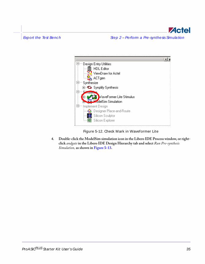
Selecting an ActionAfter loading the STAPL file, select an action from the Action list. See Table 5-3 for a definition of each action.
Programming the DeviceTo program the device:
1. In the Action list, select PROGRAM.
2. In the Device list, select the APA300 device.
3. Click the Execute button in the toolbar.
The Execute Action dialog box appears, as shown in Figure 5-32.
Table 5-3. Action Options
Option Action
QUERY_SECURITY
Checks for security feature. If the device is pro-grammed with the security feature, then this com-mand exists with Read inhibit:1 Write inhibit:1. If the security feature is not present, the values are Read inhibit:0 Write inhibit 0.
ERASE Erases the device.
READ_IDCODE Reads the device ID code.
VERIFY
Verifies whether the device was programmed with the loaded STPL file. If the wrong STPL file is loaded, an Exit 11 result appears in the log win-dow. A successful operation results in Exit 0. This command resembles the checksum command of anti-fuse product’s programming.
PROGRAM Programs the device.
DEVICE_INFO
Displays the serial number of the device, the Design Name that is programmed into the device, and the checksum that is programmed into the device.
ProASIC_UG.book Page 58 Wednesday, November 24, 2004 8:09 AM

Programming the Device Step 8 – Program the Device
ProASICPLUS Starter Kit User’s Guide 59
Figure 5-32. Execute Action Dialog Box
All the steps of the programming sequence are listed. Optional steps appear in bold. Grayed out options are required for programming and cannot be changed.
4. Make the required selections and click Execute to start programming. The progress of the programming action displays in the Log window. The message 'Exit 0' indicates that the device has successfully been programed, as shown in Figure 5-33.
ProASIC_UG.book Page 59 Wednesday, November 24, 2004 8:09 AM

Step 8 – Program the Device Programming the Device
60 ProASICPLUS Starter Kit User’s Guide
Figure 5-33. Successfully Programmed Device
ProASIC_UG.book Page 60 Wednesday, November 24, 2004 8:09 AM

Verifying the Correct Programming Step 8 – Program the Device
ProASICPLUS Starter Kit User’s Guide 61
Note: Do not interrupt the programming sequence, it may damage the device or programmer.
If you encounter any failures, please refer to the troubleshooting section of the FlashPro User’s Guide.
Verifying the Correct ProgrammingTo verify the device is programmed with the correct STAPL file:
1. Load the STAPL file.
2. In the Action list, click Verify.
3. Click the Execute button in the toolbar.
The Execute Action dialog box appears, as shown in Figure 5-34.
Figure 5-34. Execute Action Dialog Box
The default settings appear in the Execute Action dialog box.
4. Click Execute to start the verification process. A successful verification results in Exit 0, as shown in Figure 5-35. If the STPL file is different from the file used for programming, Exit 11 appears in the Log window.
Note: Do not interrupt the programming sequence, it may damage the device.
ProASIC_UG.book Page 61 Wednesday, November 24, 2004 8:09 AM

Step 8 – Program the Device Verifying the Correct Programming
62 ProASICPLUS Starter Kit User’s Guide
Figure 5-35. Successful Verification
ProASIC_UG.book Page 62 Wednesday, November 24, 2004 8:09 AM

Saving Your Log File Step 8 – Program the Device
ProASICPLUS Starter Kit User’s Guide 63
Saving Your Log FileAll FlashPro results are displayed in the Log window. Save these results into a file.
To save the log file:
1. From the File menu, click Save Log. The Save dialog box appears, as shown in Figure 5-36.
Figure 5-36. Save Dialog Box
2. Select a directory, type in the file name, and click Save. The FlashPro software saves the file.
Check Functionality of Tutorial DesignThis design uses an AND gate with inputs at pins 55 and 63 and output at pin 87. After programming the device, press switches SW1 (pin 55) and SW2 (pin 63) at the same time, and LED DS1 (pin 87) should come ON.
ProASIC_UG.book Page 63 Wednesday, November 24, 2004 8:09 AM

Step 8 – Program the Device Check Functionality of Tutorial Design
64 ProASICPLUS Starter Kit User’s Guide
ProASIC_UG.book Page 64 Wednesday, November 24, 2004 8:09 AM

65
ABoard Connections
This appendix lists the pin assignments and board connections for the ProASICPLUS Evaluation Board.
Table A-1. Board Connections
PinNumber
APA075 APA150 APA300APA45
0APA60
0APA75
0APA100
0
1 GND GND GND GND GND GND GND
2 I/O I/O I/O I/O I/O I/O I/O
3 I/O I/O I/O I/O I/O I/O I/O
4 I/O I/O I/O I/O I/O I/O I/O
5 I/O I/O I/O I/O I/O I/O I/O
6 I/O I/O I/O I/O I/O I/O I/O
7 I/O I/O I/O I/O I/O I/O I/O
8 I/O I/O I/O I/O I/O I/O I/O
9 I/O I/O I/O I/O I/O I/O I/O
10 I/O I/O I/O I/O I/O I/O I/O
11 I/O I/O I/O I/O I/O I/O I/O
12 I/O I/O I/O I/O I/O I/O I/O
13 I/O I/O I/O I/O I/O I/O I/O
14 I/O I/O I/O I/O I/O I/O I/O
15 I/O I/O I/O I/O I/O I/O I/O
16 VDD VDD VDD VDD VDD VDD VDD
17 GND GND GND GND GND GND GND
18 I/O I/O I/O I/O I/O I/O I/O
19 I/O I/O I/O I/O I/O I/O I/O
ProASIC_UG.book Page 65 Wednesday, November 24, 2004 8:09 AM

66 ProASICPLUS Starter Kit User’s Guide
20 I/O I/O I/O I/O I/O I/O I/O
21 I/O I/O I/O I/O I/O I/O I/O
22 VDDP VDDP VDDP VDDP VDDP VDDP VDDP
23I/O (GLMX)
I/O (GLMX)
I/O (GLMX)
I/O (GLMX)
I/O (GLMX)
I/O (GLMX)
I/O (GLMX)
24 GL GL GL GL GL GL GL
25 AGND AGND AGND AGND AGND AGND AGND
26 NPECL NPECL NPECL NPECL NPECL NPECL NPECL
27 AVDD AVDD AVDD AVDD AVDD AVDD AVDD
28PPECL (I/P)
PPECL (I/P)
PPECL (I/P)
PPECL (I/P)
PPECL (I/P)
PPECL (I/P)
PPECL (I/P)
29 GND GND GND GND GND GND GND
30 GL GL GL GL GL GL GL
31 I/O I/O I/O I/O I/O I/O I/O
32 I/O I/O I/O I/O I/O I/O I/O
33 I/O I/O I/O I/O I/O I/O I/O
34 I/O I/O I/O I/O I/O I/O I/O
35 I/O I/O I/O I/O I/O I/O I/O
36 VDD VDD VDD VDD VDD VDD VDD
37 I/O I/O I/O I/O I/O I/O I/O
38 I/O I/O I/O I/O I/O I/O I/O
Table A-1. Board Connections
PinNumber
APA075 APA150 APA300APA45
0APA60
0APA75
0APA100
0
ProASIC_UG.book Page 66 Wednesday, November 24, 2004 8:09 AM

ProASICPLUS Starter Kit User’s Guide 67
39 I/O I/O I/O I/O I/O I/O I/O
40 VDDP VDDP VDDP VDDP VDDP VDDP VDDP
41 GND GND GND GND GND GND GND
42 I/O I/O I/O I/O I/O I/O I/O
43 I/O I/O I/O I/O I/O I/O I/O
44 I/O I/O I/O I/O I/O I/O I/O
45 I/O I/O I/O I/O I/O I/O I/O
46 I/O I/O I/O I/O I/O I/O I/O
47 I/O I/O I/O I/O I/O I/O I/O
48 I/O I/O I/O I/O I/O I/O I/O
49 I/O I/O I/O I/O I/O I/O I/O
50 I/O I/O I/O I/O I/O I/O I/O
51 I/O I/O I/O I/O I/O I/O I/O
52 GND GND GND GND GND GND GND
53 VDDP VDDP VDDP VDDP VDDP VDDP VDDP
54 I/O I/O I/O I/O I/O I/O I/O
55 I/O I/O I/O I/O I/O I/O I/O
56 I/O I/O I/O I/O I/O I/O I/O
57 I/O I/O I/O I/O I/O I/O I/O
58 I/O I/O I/O I/O I/O I/O I/O
59 I/O I/O I/O I/O I/O I/O I/O
Table A-1. Board Connections
PinNumber
APA075 APA150 APA300APA45
0APA60
0APA75
0APA100
0
ProASIC_UG.book Page 67 Wednesday, November 24, 2004 8:09 AM

68 ProASICPLUS Starter Kit User’s Guide
60 I/O I/O I/O I/O I/O I/O I/O
61 I/O I/O I/O I/O I/O I/O I/O
62 I/O I/O I/O I/O I/O I/O I/O
63 I/O I/O I/O I/O I/O I/O I/O
64 I/O I/O I/O I/O I/O I/O I/O
65 GND GND GND GND GND GND GND
66 I/O I/O I/O I/O I/O I/O I/O
67 I/O I/O I/O I/O I/O I/O I/O
68 I/O I/O I/O I/O I/O I/O I/O
69 I/O I/O I/O I/O I/O I/O I/O
70 I/O I/O I/O I/O I/O I/O I/O
71 VDD VDD VDD VDD VDD VDD VDD
72 VDDP VDDP VDDP VDDP VDDP VDDP VDDP
73 I/O I/O I/O I/O I/O I/O I/O
74 I/O I/O I/O I/O I/O I/O I/O
75 I/O I/O I/O I/O I/O I/O I/O
76 I/O I/O I/O I/O I/O I/O I/O
77 I/O I/O I/O I/O I/O I/O I/O
78 I/O I/O I/O I/O I/O I/O I/O
79 I/O I/O I/O I/O I/O I/O I/O
80 I/O I/O I/O I/O I/O I/O I/O
Table A-1. Board Connections
PinNumber
APA075 APA150 APA300APA45
0APA60
0APA75
0APA100
0
ProASIC_UG.book Page 68 Wednesday, November 24, 2004 8:09 AM

ProASICPLUS Starter Kit User’s Guide 69
81 GND GND GND GND GND GND GND
82 I/O I/O I/O I/O I/O I/O I/O
83 I/O I/O I/O I/O I/O I/O I/O
84 I/O I/O I/O I/O I/O I/O I/O
85 I/O I/O I/O I/O I/O I/O I/O
86 I/O I/O I/O I/O I/O I/O I/O
87 I/O I/O I/O I/O I/O I/O I/O
88 VDD VDD VDD VDD VDD VDD VDD
89 VDDP VDDP VDDP VDDP VDDP VDDP VDDP
90 I/O I/O I/O I/O I/O I/O I/O
91 I/O I/O I/O I/O I/O I/O I/O
92 I/O I/O I/O I/O I/O I/O I/O
93 I/O I/O I/O I/O I/O I/O I/O
94 I/O I/O I/O I/O I/O I/O I/O
95 I/O I/O I/O I/O I/O I/O I/O
96 I/O I/O I/O I/O I/O I/O I/O
97 GND GND GND GND GND GND GND
98 I/O I/O I/O I/O I/O I/O I/O
99 I/O I/O I/O I/O I/O I/O I/O
100 I/O I/O I/O I/O I/O I/O I/O
101 TCK TCK TCK TCK TCK TCK TCK
Table A-1. Board Connections
PinNumber
APA075 APA150 APA300APA45
0APA60
0APA75
0APA100
0
ProASIC_UG.book Page 69 Wednesday, November 24, 2004 8:09 AM

70 ProASICPLUS Starter Kit User’s Guide
102 TDI TDI TDI TDI TDI TDI TDI
103 TMS TMS TMS TMS TMS TMS TMS
104 VDDP VDDP VDDP VDDP VDDP VDDP VDDP
105 GND GND GND GND GND GND GND
106 VPP VPP VPP VPP VPP VPP VPP
107 VPN VPN VPN VPN VPN VPN VPN
108 TDO TDO TDO TDO TDO TDO TDO
109 TRST TRST TRST TRST TRST TRST TRST
110 RCK RCK RCK RCK RCK RCK RCK
111 I/O I/O I/O I/O I/O I/O I/O
112 I/O I/O I/O I/O I/O I/O I/O
113 I/O I/O I/O I/O I/O I/O I/O
114 I/O I/O I/O I/O I/O I/O I/O
115 I/O I/O I/O I/O I/O I/O I/O
116 I/O I/O I/O I/O I/O I/O I/O
117 I/O I/O I/O I/O I/O I/O I/O
118 I/O I/O I/O I/O I/O I/O I/O
119 I/O I/O I/O I/O I/O I/O I/O
120 I/O I/O I/O I/O I/O I/O I/O
121 I/O I/O I/O I/O I/O I/O I/O
122 GND GND GND GND GND GND GND
Table A-1. Board Connections
PinNumber
APA075 APA150 APA300APA45
0APA60
0APA75
0APA100
0
ProASIC_UG.book Page 70 Wednesday, November 24, 2004 8:09 AM

ProASICPLUS Starter Kit User’s Guide 71
123 VDDP VDDP VDDP VDDP VDDP VDDP VDDP
124 I/O I/O I/O I/O I/O I/O I/O
125 I/O I/O I/O I/O I/O I/O I/O
126 VDD VDD VDD VDD VDD VDD VDD
127 I/O I/O I/O I/O I/O I/O I/O
128 GL GL GL GL GL GL GL
129PPECL (I/P)
PPECL (I/P)
PPECL (I/P)
PPECL (I/P)
PPECL (I/P)
PPECL (I/P)
PPECL (I/P)
130 GND GND GND GND GND GND GND
131 AVDD AVDD AVDD AVDD AVDD AVDD AVDD
132 NPECL NPECL NPECL NPECL NPECL NPECL NPECL
133 AGND AGND AGND AGND AGND AGND AGND
134 GL GL GL GL GL GL GL
135I/O (GLMX)
I/O (GLMX)
I/O (GLMX)
I/O (GLMX)
I/O (GLMX)
I/O (GLMX)
I/O (GLMX)
136 I/O I/O I/O I/O I/O I/O I/O
137 I/O I/O I/O I/O I/O I/O I/O
138 VDDP VDDP VDDP VDDP VDDP VDDP VDDP
139 I/O I/O I/O I/O I/O I/O I/O
140 I/O I/O I/O I/O I/O I/O I/O
141 GND GND GND GND GND GND GND
Table A-1. Board Connections
PinNumber
APA075 APA150 APA300APA45
0APA60
0APA75
0APA100
0
ProASIC_UG.book Page 71 Wednesday, November 24, 2004 8:09 AM
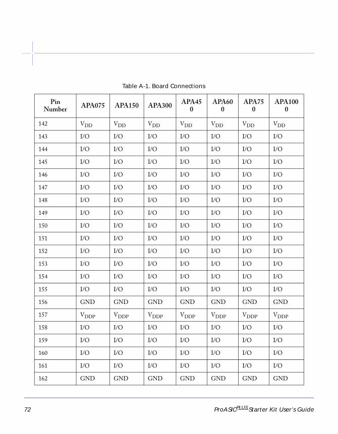
72 ProASICPLUS Starter Kit User’s Guide
142 VDD VDD VDD VDD VDD VDD VDD
143 I/O I/O I/O I/O I/O I/O I/O
144 I/O I/O I/O I/O I/O I/O I/O
145 I/O I/O I/O I/O I/O I/O I/O
146 I/O I/O I/O I/O I/O I/O I/O
147 I/O I/O I/O I/O I/O I/O I/O
148 I/O I/O I/O I/O I/O I/O I/O
149 I/O I/O I/O I/O I/O I/O I/O
150 I/O I/O I/O I/O I/O I/O I/O
151 I/O I/O I/O I/O I/O I/O I/O
152 I/O I/O I/O I/O I/O I/O I/O
153 I/O I/O I/O I/O I/O I/O I/O
154 I/O I/O I/O I/O I/O I/O I/O
155 I/O I/O I/O I/O I/O I/O I/O
156 GND GND GND GND GND GND GND
157 VDDP VDDP VDDP VDDP VDDP VDDP VDDP
158 I/O I/O I/O I/O I/O I/O I/O
159 I/O I/O I/O I/O I/O I/O I/O
160 I/O I/O I/O I/O I/O I/O I/O
161 I/O I/O I/O I/O I/O I/O I/O
162 GND GND GND GND GND GND GND
Table A-1. Board Connections
PinNumber
APA075 APA150 APA300APA45
0APA60
0APA75
0APA100
0
ProASIC_UG.book Page 72 Wednesday, November 24, 2004 8:09 AM

ProASICPLUS Starter Kit User’s Guide 73
163 I/O I/O I/O I/O I/O I/O I/O
164 I/O I/O I/O I/O I/O I/O I/O
165 I/O I/O I/O I/O I/O I/O I/O
166 I/O I/O I/O I/O I/O I/O I/O
167 I/O I/O I/O I/O I/O I/O I/O
168 I/O I/O I/O I/O I/O I/O I/O
169 I/O I/O I/O I/O I/O I/O I/O
170 VDDP VDDP VDDP VDDP VDDP VDDP VDDP
171 VDD VDD VDD VDD VDD VDD VDD
172 I/O I/O I/O I/O I/O I/O I/O
173 I/O I/O I/O I/O I/O I/O I/O
174 I/O I/O I/O I/O I/O I/O I/O
175 I/O I/O I/O I/O I/O I/O I/O
176 I/O I/O I/O I/O I/O I/O I/O
177 I/O I/O I/O I/O I/O I/O I/O
178 GND GND GND GND GND GND GND
179 I/O I/O I/O I/O I/O I/O I/O
180 I/O I/O I/O I/O I/O I/O I/O
181 I/O I/O I/O I/O I/O I/O I/O
182 I/O I/O I/O I/O I/O I/O I/O
183 I/O I/O I/O I/O I/O I/O I/O
Table A-1. Board Connections
PinNumber
APA075 APA150 APA300APA45
0APA60
0APA75
0APA100
0
ProASIC_UG.book Page 73 Wednesday, November 24, 2004 8:09 AM

74 ProASICPLUS Starter Kit User’s Guide
184 I/O I/O I/O I/O I/O I/O I/O
185 I/O I/O I/O I/O I/O I/O I/O
186 VDDP VDDP VDDP VDDP VDDP VDDP VDDP
187 VDD VDD VDD VDD VDD VDD VDD
188 I/O I/O I/O I/O I/O I/O I/O
189 I/O I/O I/O I/O I/O I/O I/O
190 I/O I/O I/O I/O I/O I/O I/O
191 I/O I/O I/O I/O I/O I/O I/O
192 I/O I/O I/O I/O I/O I/O I/O
193 I/O I/O I/O I/O I/O I/O I/O
194 I/O I/O I/O I/O I/O I/O I/O
195 GND GND GND GND GND GND GND
196 I/O I/O I/O I/O I/O I/O I/O
197 I/O I/O I/O I/O I/O I/O I/O
198 I/O I/O I/O I/O I/O I/O I/O
199 I/O I/O I/O I/O I/O I/O I/O
200 I/O I/O I/O I/O I/O I/O I/O
201 I/O I/O I/O I/O I/O I/O I/O
202 I/O I/O I/O I/O I/O I/O I/O
203 I/O I/O I/O I/O I/O I/O I/O
204 I/O I/O I/O I/O I/O I/O I/O
Table A-1. Board Connections
PinNumber
APA075 APA150 APA300APA45
0APA60
0APA75
0APA100
0
ProASIC_UG.book Page 74 Wednesday, November 24, 2004 8:09 AM

ProASICPLUS Starter Kit User’s Guide 75
205 I/O I/O I/O I/O I/O I/O I/O
206 I/O I/O I/O I/O I/O I/O I/O
207 I/O I/O I/O I/O I/O I/O I/O
208 VDDP VDDP VDDP VDDP VDDP VDDP VDDP
Table A-1. Board Connections
PinNumber
APA075 APA150 APA300APA45
0APA60
0APA75
0APA100
0
ProASIC_UG.book Page 75 Wednesday, November 24, 2004 8:09 AM

76 ProASICPLUS Starter Kit User’s Guide
ProASIC_UG.book Page 76 Wednesday, November 24, 2004 8:09 AM

77
BBoard Schematics
This appendix provides illustrations of the ProASICPLUS Evaluation Board.
Top-Level ViewFigure B-37 illustrates a top-level view of the ProASICPLUS Evaluation Board.
Figure B-37. ProASICPLUS Evaluation Board: Top-level View
ProASIC_UG.book Page 77 Wednesday, November 24, 2004 8:09 AM

Bottom-Level View
78 ProASICPLUS Starter Kit User’s Guide
Bottom-Level ViewFigure B-38 illustrates a bottom-level view of the ProASICPLUS Evaluation Board, while Figure B-39 illustrates the ProASICPLUS Evaluation Board schematic.
Figure B-38. ProASICPLUS Evaluation Board: Bottom-level View
ProASIC_UG.book Page 78 Wednesday, November 24, 2004 8:09 AM

Bottom-Level View
ProASICPLUS Starter Kit User’s Guide 79
Figure B-39. ProASICPLUS Evaluation Board Schematic
C91 2
C11
1 2
C15
1 2
C10
1 2
C61 2
+3.3
v
C71 2
C13
1 2
Good
Powe
rEn
able
InInOu
tOu
t
Gnd
TPS7
7633
PWP
VR1
6 7 5
13 14 16
3
C19
1 2
1.0K
R21
1 2
C17
12
+3.3
v
JP21
2
330
R41 2
JP31
2
HDR4
52
C36
1 2
C12
1 2
C51 2
Gnd
Out
V+40
.000
MHz
Oscillator
Y13
4 2
TP2 4
TP2 5
TP2 1
TP2 2
JP4
12
+3.3
v
+3.3
v
330
R31 2
220
R21 2
C25
1 2
Glob
alor
I/O
VDD(+2.5v)
NPECL1
Analog
Gnd
VDDP
(2.5
/3.3
v)
Ground
I/O
I/O
I/O
I/O
I/O
I/O
I/O
I/O
I/O
I/O
I/O
I/O
I/O
I/O
I/O
I/O
I/O
I/O
I/O
Ground
U11 2 3 4 5 6 7 8 9
10 11 12 13 14 15 16 17 18 19 20 21 22 23 24 25 26
C23
1 2
+2.5
v
Glob
alor
I/O
Anal
ogGn
d
NPEC
L2
Grou
nd
VDDP
(2.5
/3.3
v)
I/O
AVDD
VDD(
+2.5
v)
Grou
nd
I/O
I/O
I/O
I/O
I/O
I/O
I/O
I/O
I/O
I/O
I/O
I/O
I/O
I/O
I/O
I/O
I/O
U1131
132
133
134
135
136
137
138
139
140
141
142
143
144
145
146
147
148
149
150
151
152
153
154
155
156
P110
C31 2
C22
1 2
P225
P223
P221
P215
Glob
alor
I/O
AVDD(+2.5v)
PPECL1
VDD(+2.5v)
VDDP
(2.5
/3.3
v)
Ground
I/O
I/O
I/O
I/O
I/O
I/O
I/O
I/O
I/O
I/O
I/O
I/O
I/O
I/O
I/O
I/O
I/O
I/O
Ground
Ground
U127 28 29 30 31 32 33 34 35 36 37 38 39 40 41 42 43 44 45 46 47 48 49 50 51 52
Grou
nd
VDDP
(2.5
/3.3
v)
VDDP
(2.5
/3.3
v)
I/O
I/O
VDD(+2.5v)
I/O
I/O
I/O
I/O
I/O
I/O
I/O
I/O
I/O
I/O
I/O
I/O
I/O
I/O
I/O
I/O
I/O
I/O
I/O
I/O
U1183
184
185
186
187
188
189
190
191
192
193
194
195
196
197
198
199
200
201
202
203
204
205
206
207
208
VDD(
+2.5
v)
VDDP
(2.5
/3.3
v)
VDDP
(2.5
/3.3
v)
I/O
I/O
I/O
I/O
I/O
I/O
I/O
I/O
I/O
I/O
I/O
I/O
I/O
I/O
I/O
I/O
I/O
I/O
I/O
I/O
I/O
I/O
Grou
nd
U1
53 54 55 56 57 58 59 60 61 62 63 64 65 66 67 68 69 70 71 72 73 74 75 76 77 78
TCK
TDI
TMS
VDD(
+2.5
v)
VDDP
(2.5
/3.3
v)
VDDP
(2.5
/3.3
v)
Grou
nd
I/O
I/O
I/O
I/O
I/O
I/O
I/O
I/O
I/O
I/O
I/O
I/O
I/O
I/O
I/O
I/O
I/O
I/O
Grou
nd
U179 80 81 82 83 84 85 86 87 88 89 90 91 92 93 94 95 96 97 98 99
100
101
102
103
104
Glob
alor
I/O
TRST
PPEC
L2
RCK
TDO
VPN
VPP
VDD(
+2.5
v)
VDDP
(2.5
/3.3
v)
Grou
nd
Grou
nd
I/O
I/O
I/O
I/O
I/O
I/O
I/O
I/O
I/O
I/O
I/O
I/O
I/O
I/O
Grou
ndU1
105
106
107
108
109
110
111
112
113
114
115
116
117
118
119
120
121
122
123
124
125
126
127
128
129
130
Grou
nd
VDDP
(2.5
/3.3
v)
VDDP
(2.5
/3.3
v)
I/O
I/O
VDD(+2.5v)
Grou
nd
I/O
I/O
I/O
I/O
I/O
I/O
I/O
I/O
I/O
I/O
I/O
I/O
I/O
I/O
I/O
I/O
I/O
I/O
I/O
U1
157
158
159
160
161
162
163
164
165
166
167
168
169
170
171
172
173
174
175
176
177
178
179
180
181
182
P115
P211
P210
220
R51 2
HDR4
51
HDR4
50
HDR4
49
HDR4
48
HDR4
47
HDR4
46
HDR4
45
HDR4
44
HDR4
43
HDR4
42
HDR4
41
HDR4
40
C81 2
C21
1 2
C27
1 2
C28
1 2
P19
P13
P113
P15
C16
1 2
HDR4
39
HDR4
38
HDR4
37
C24
1 2
P125
P123
P121
P29
P117
P11
HDR4
36
HDR4
35
HDR4
34
HDR4
33
HDR4
32
HDR4
31
HDR4
30
HDR4
27
HDR4
28
HDR4
29
HDR4
26
HDR4
25
HDR4
24
HDR4
23
HDR4
22
HDR4
21
HDR4
20
HDR4
19
HDR4
18
HDR4
17
HDR4
16
HDR4
15
HDR4
14
HDR4
13
HDR4
12
HDR4
11
HDR4
10
HDR4
9
HDR4
8
HDR4
7
HDR4
6
HDR4
5
HDR4
4
HDR4
1
HDR4
2
HDR4
3
HDR3
52
HDR3
51
HDR3
50
C14
1 2
HDR3
49
HDR3
48
HDR3
47
HDR3
46
HDR3
45
HDR3
44
C18
1 2
Good
Powe
rEn
able
InInOu
tOu
t
Gnd
TPS7
7625
PWP
VR2
6 7 5
13 14 16
3
SW2
1 234
C20
1 2
HDR3
43
HDR3
42
HDR3
41
HDR3
40
HDR3
39
HDR3
38
HDR3
37
HDR3
36
HDR3
35
HDR3
34
HDR3
33
HDR3
32
HDR3
31
HDR3
30
HDR3
27
HDR3
28
HDR3
29
HDR3
26
HDR3
25
HDR3
24
HDR3
23
HDR3
22
HDR3
21
HDR3
20
HDR3
19
HDR3
18
HDR3
17
HDR3
16
HDR3
15
HDR3
14
HDR3
13
HDR3
12
HDR3
11
HDR3
10
HDR3
9
HDR3
8
HDR3
7
HDR3
6
HDR3
5
HDR3
4
P126
HDR3
1
HDR3
2
HDR3
3
HDR2
52
HDR2
51
HDR2
50
HDR2
49
HDR2
48
P124
P122
P120
P118
P116
P114
P112
P17
P18
P16
P14
P119
P12
P111
HDR2
47
HDR2
46
C26
1
2
P23
P213
P25
P217
P21
P226
P224
P222
P220
HDR2
45
P218
P216
HDR2
44
HDR2
43
HDR2
42
P214
P212
P27
P28
P26
P24
HDR2
41
HDR2
40
HDR2
39
P219
HDR2
38
HDR2
37
HDR2
36
HDR2
35
HDR2
34
HDR2
33
P22
HDR2
32
HDR2
31
HDR2
30
HDR2
27
HDR2
28
HDR2
29
HDR2
26
HDR2
25
HDR2
24
HDR2
23
HDR2
22
HDR2
21
HDR2
20
HDR2
19
HDR2
18
HDR2
17
HDR2
16
HDR2
15
HDR2
14
HDR2
13
HDR2
12
HDR2
11
HDR2
10
HDR2
9
HDR2
8
HDR2
7
HDR2
6
HDR2
5
HDR2
4
HDR2
1
HDR2
2
HDR2
3
HDR1
52
HDR1
51
HDR1
50
HDR1
49
HDR1
48
HDR1
47
HDR1
46
HDR1
45
HDR1
44
HDR1
43
HDR1
42
HDR1
41
HDR1
40
HDR1
39
HDR1
38
HDR1
37
HDR1
36
HDR1
35
HDR1
34
HDR1
33
HDR1
32
HDR1
31
HDR1
30
HDR1
27
HDR1
28
HDR1
29
HDR1
26
HDR1
25
HDR1
24
HDR1
23
HDR1
22
HDR1
21
HDR1
20
HDR1
19
HDR1
18
HDR1
17
HDR1
16
HDR1
15
HDR1
14
HDR1
13
HDR1
12
HDR1
11
HDR1
10
HDR1
9
HDR1
8
HDR1
7
HDR1
6
HDR1
5
HDR1
4
HDR1
1
HDR1
2
HDR1
3
1.0K
R11
1 2
C11 2
C21 2
OnSW5
12
345
6
JP16
12JP
151
2JP14
12JP
131
2JP12
12
3 21DC
JP11
12
JP1 2 13
DS9
12
330
R11 2
JP91
2
1.0K
R22
1 2
MMBT
2222
Q1
3 2
12.
0KR7 1
2
2.0K
R81 2
150
R10
1 2
+5v
+3.3
v
+5v
RC
Q Q
CLR
74LV
123A
U2
5 12910
11
67
+3.3
v
+3.3
v
220K
R9 12
18K
R6 12
C32
12C3
51 2
1000pF
C30
12
C29
1 2
JP10
12
JP5
12
TP2 3
150
R19
1 2
DS1
12DS2
12DS3
12DS
4
12DS5
12DS6
12DS
7
12DS
8
12
150
R17
1 215
0R18
1 215
0R16
1 215
0R1
51 2
150
R13
1 215
0R1
41 2
150
R12
1 2
+3.3
v
Ground
74LV123A
U2
16
8
+3.3
v
JP17
12
C31
1 2
JP8
12
JP6
12
JP7
12
RC
Q Q
CLR
74LV
123A
U2
13 412
3
1415
PB1
1 234
1.0K
R20
1 2
330
R26
12
DS10
12
C33
1 2
+3.3
v
SW4
1 234
1.0K
R23
1 2C4
1 2
C34
1 2
330
R24
12
SW3
1 234
SW1
1 234
330
R25
12
330
R28
12
330
R27
12
C37
1 2
GL-128
RCK
TRST
B
TDO
VPN
VPP
TMS
TDI
TCK
U1-94
U1-95
U1-92
U1-93
U1-90
U1-91
U1-87
U1-69
U1-63
U1-55
GND
GND
GND
GND
GND
GND
GND
GND
GND
GND
GND
GND
GND
GND
GND
GND
GND
GND
GND
GND
GND
GND
GND
GND
GND
GND
GND
GND
GND
GND
GND
GND
GND
GND
GND
GND
GND
GND
GND
GND
GND
GND
GND
GND
GND
GND
GND
GND
GND
GND
GND
GND
GND
GND
GND
U1-96
U1-79
9V-IN
EXT-IN
EXT-IN
AGND
AGND
AVDD
AVDD
VDDP
VDDP
VDDP
+2.5V
+2.5V
+2.5V
+3.3V
+3.3V
+3.3
V
+3.3
V
+3.3
V
+3.3
V
+3.3V
+3.3V
+3.3
V
10-6
-02
APAx
xx-2
Rev.
1.0
Assy
.#AP
Axxx
-503
Rev.
A
ToFP
GAPi
n96
ToFP
GAPi
n94
ToFP
GAPi
n92
ToFP
GAPi
n90
ToFP
GAPi
n87
VDD
VDD
VDPP
VDPP
VDD
(+2.
5v)
VDD
VDD
VDDP
VDDP
IMPO
RTAN
T:
Equa
l+3.3
vOR
+2.5
v
Inst
all
AJu
mper
AtJP1To
Select
VDDP
VDDP
VDDP
VDDP
Ground
+2.5
v
6-8V
DC
ToFP
GAPi
n79
ToFP
GAPi
n69
ToFP
GAPi
n63
ToFP
GAPi
n55
ToFP
GAPi
n95
ToFP
GAPi
n93
ToFP
GAPi
n91
ToFPGA
Pin
128
220
InputTo
Pin30
PressForClock
1
Inst
all
Jump
erTo
Manual
Clock
Input
DCSu
pply
Exte
rnal
Conn
ect
ToFP
GAI/
O
APAx
xx-2
.Sch
Augu
st9,
2002
stal
led
atth
efa
ctor
yR5
and
R6are
not
in-
Note
:
ToU1
Pin
24(G
loba
lIn
put)
and
HDR1
Pin
24
GL GL
GND
GND
GND
AGND
GL
GND
GND
GND
GND
GNDGL
TRST
GND
GND
GND
GND
GND
GND
GND
AGNDGND
P1 P2
P1P1P2
P2
HDR4
HDR4
HDR3
HDR3
HDR2
HDR2
HDR1
HDR1
Ana.+2.5v
Ana.Gnd
AGND
AVDD
AVDD(+2.5v)
TRST
B
RCK
TMS
TDO
TDI
TCK
VPN
VPP
NoCo
nnec
tion
From
Programmer
TRST
B
RCK
TMS
TDO
TDI
TCK
Ground
Ground
Ground
Ground
Ground
GroundVPN
VPP
PPECL2
NPECL2
AVDDRCK
TDO
VPN
VPP
TMS
TDI
TCK
PPEC
L1
NPEC
L1I/O
VDDP
(2.5
/3.3
v)
VDDP
(2.5
/3.3
v)
VDDP
(2.5
/3.3
v)
VDDP
(2.5
/3.3
v)
VDDP
(2.5
/3.3
v)
VDDP
(2.5
/3.3
v)
VDDP
(2.5
/3.3
v)
VDDP
(2.5
/3.3
v)
VDDP
(2.5
/3.3
v)
VDDP
(2.5
/3.3
v)
VDDP
(2.5
/3.3
v)
VDDP
(2.5
/3.3
v)
VDD(
+2.5
v)
VDD(
+2.5
v)
VDD(+2.5v)
VDD(+2.5v)
VDD(+2.5v)
VDD(+2.5v)
VDD(
+2.5
v)
VDD(
+2.5
v)
I/O
I/O
I/O
I/O
I/O
I/O
I/O
I/O
I/O
I/O
I/O
I/O
I/O
I/O
I/O
I/O
I/O
I/O
I/O
I/O
I/O
I/O
I/O
I/O
I/O
I/O
I/O
I/O
I/O
I/O
I/O
I/O
I/O
I/O
I/O
I/O
I/O
I/O
I/O
I/O
I/O
I/O
I/O
I/O
I/O
I/O
I/O
I/O
I/O
I/O
I/O
I/O
I/O
I/O
I/O
I/O
I/O
I/O
I/O
I/O
I/O
I/O
I/O
I/O
I/O
I/O
I/O
I/O
I/O
I/O
I/O
I/O
I/O
I/O
I/O
I/O
I/O
I/O
I/O
I/O
I/O
I/O
I/O
I/O
I/O
I/O
I/O
I/O
I/O
I/O
I/O
I/O
I/O
I/O
I/O
I/O
I/O
I/O
I/O
I/O
I/O
I/O
I/O
I/O
I/O
I/O
I/O
I/O
I/O
I/O
I/O
I/O
I/O
I/O
I/O
I/O
I/O
I/O
I/O
I/O
I/O
I/O
I/O
I/O
I/O
I/O
I/O
I/O
I/O
I/O
I/O
I/O
I/O
I/O
I/O
I/O
I/O
I/O
I/O
I/O
I/O
I/O
I/O
I/O
I/O
I/O
I/O
I/O
I/O
I/O
I/O
+2.5
v
Demo
nstr
atio
nBo
ard
Northridge,CA
91326
Electronics
RAST
URNo
Conn
ecti
on
From
Programmer
TRST
B
RCK
TMS
TDO
TDI
TCK
Grou
nd
Grou
nd
Grou
nd
Grou
nd
Grou
nd
Grou
ndVPN
VPP
Sche
mati
cDi
agra
m-Dr
awin
gNu
mber
:
PWB
Numb
er:
R.A.
Stur
laDr
awn
By:
Date
:
OfSh
eet
#Re
vise
d:
II
4321
4321
HG
FE
DC
BA
HG
FE
DC
BA
11
ProASIC_UG.book Page 79 Wednesday, November 24, 2004 8:09 AM

Bottom-Level View
80 ProASICPLUS Starter Kit User’s Guide
ProASIC_UG.book Page 80 Wednesday, November 24, 2004 8:09 AM

81
CProduct Support
Actel backs its products with various support services including Customer Service, a Customer Applications Center, a web site, an FTP site, electronic mail, and worldwide sales offices. This appendix contains information about contacting Actel and using these support services.
Actel U.S. Toll-Free LineUse the Actel toll-free line to contact Actel for sales information, technical support, requests for literature about Actel and Actel products, Customer Service, investor information, and using the Action Facts service.
The Actel toll-free line is (888) 99-ACTEL.
Customer ServiceContact Customer Service for nontechnical product support, such as product pricing, product upgrades, update information, order status, and authorization.
From Northeast and North Central U.S.A., call (650) 318-4480.From Southeast and Southwest U.S.A., call (650) 318-4480.From South Central U.S.A., call (650) 318-4434.From Northwest U.S.A., call (650) 318-4434.From Canada, call (650) 318-4480.From Europe, call (650) 318-4252 or +44 (0) 1276 401500.From Japan, call (650) 318-4743.From the rest of the world, call (650) 318-4743.Fax, from anywhere in the world (650) 318-8044.
Customer Applications CenterActel staffs its Customer Applications Center with highly skilled engineers who can help answer your hardware, software, and design questions. The Applications Center spends a great deal of time creating application notes and answers to FAQs. So, before you contact us, please visit our online resources. It is very likely we have already answered your question(s).
Guru Automated Technical SupportGuru is a web-based automated technical support system accessible through the Actel home page (http://www.actel.com/custsup/search.html). Guru provides answers to technical questions about Actel products. Many answers include diagrams, illustrations, and links to other resources on the Actel web site. Guru is available 24 hours a day, seven days a week.
ProASIC_UG.book Page 81 Wednesday, November 24, 2004 8:09 AM

Web Site
82 ProASICPLUS Starter Kit User’s Guide
Web SiteActel has a World Wide Web home page where you can browse a variety of technical and nontechnical information. Use a Net browser (Netscape recommended) to access Actel’s home page.
The URL is http://www.actel.com. You are welcome to share the resources provided on the Internet.
Be sure to visit the Technical Documentation area on our web site, which contains information regarding products, technical services, current manuals, and release notes.
FTP SiteActel has an anonymous FTP site located at ftp://ftp.actel.com. Here you can obtain library updates, software patches, design files, and data sheets.
Contacting the Customer Applications CenterHighly skilled engineers staff the Customer Applications Center from 7:30 A.M. to 5:00 P.M., Pacific Time, Monday through Friday. Several ways of contacting the Center follow:
You can communicate your technical questions to our e-mail address and receive answers back by e-mail, fax, or phone. Also, if you have design problems, you can e-mail your design files to receive assistance. We constantly monitor the e-mail account throughout the day. When sending your request to us, please be sure to include your full name, company name, and your contact information for efficient processing of your request.
The technical support e-mail address is [email protected].
Telephone
Our Technical Message Center answers all calls. The center retrieves information, such as your name, company name, phone number and your question, and then issues a case number. The Center then forwards the information to a queue where the first available application engineer receives the data and returns your call. The phone hours are from 7:30 A.M. to 5:00 A.M., Pacific Time, Monday through Friday.
The Customer Applications Center number is (800) 262-1060.
European customers can call +44 (0) 1256 305600.
ProASIC_UG.book Page 82 Wednesday, November 24, 2004 8:09 AM

Headquarters Worldwide Sales Offices
ProASICPLUS Starter Kit User’s Guide 83
Worldwide Sales Offices
.
HeadquartersActel Corporation2051 Stierlin CourtMountain View, California 94086Toll Free: 888.99.ACTELTel: 650.318.4200Fax: 650.318.4600
US Sales Offices
CaliforniaBay Area
Tel: 650.318.4200Fax: 650.318.4600
IrvineTel: 949.788.0980Fax: 949.788.0822
Newbury ParkTel: 805.375.5769Fax: 805.375.5749
ColoradoTel: 303.420.4335Fax: 303.420.4336
FloridaTel: 407.977.6846Fax: 407.977.6847
GeorgiaTel: 770.623.3960Fax: 770.831.0055
IllinoisTel: 847.259.1501Fax: 847.259.1572
MassachusettsTel: 978.244.3800Fax: 978.244.3820
MinnesotaTel: 651.917.9116Fax: 651.917.9114
North CarolinaTel: 919.654.4529Fax: 919.674.0055
PennsylvaniaTel: 215.794.2050Fax: 215.706.0680
TexasTel: 972.312.8700Fax: 972.312.8707
International Sales Offices
CanadaSuite 106235 Stafford Rd. West,Nepean, Ontario K2H 9C1Tel: 613.726.7575Fax: 613.726.8666
France361 Avenue General de Gaulle92147 Clamart CedexTel: +33 (0)1.40.83.11.00Fax: +33 (0)1.40.94.11.04
GermanyActel GmbHLohweg 27, D-85375 Neufahrn, GermanyPhone: +49.(0)81.659.584.0Fax: +49.(0)81.659.584.10Hong Kong39th Floor, One Pacific Place, 88 Queensway Admiralty, Hong Kong Tel: +011.852.227.35712Fax: +011.852.227.35999
ItalyVia Giovanni da Udine No. 3420156 MilanoTel: +39 (0)2.3809.3259Fax: +39 (0)2.3809.3260
JapanEXOS Ebisu Building 4F1-24-14 Ebisu Shibuya-kuTokyo 150Tel: +81 (0)3.3445.7671Fax: +81 (0)3.3445.7668
Korea30th Floor, ASEM Tower,159-1 Samsung-dongKangnam-ku, SeoulTel: +82 (0)2.6001.3382Fax: +82 (0)2.6001.3030
NordicSveavagen 49Djursholm 18262Sweden
Tel: +46.8544.99025 Fax: +46.8544.99026
Taiwan4F-3, No. 75, Sec. 1,Hsin-Tai-Wu Road,Hsi-chih, Taipei, 221 Tel: +886.928.273190Fax: +886.226.626251
United KingdomDunlop House,Riverside WayCamberley,Surrey GU15 3YLTel: +44 (0)1276.401450Fax: +44 (0)1276.401490
ProASIC_UG.book Page 83 Wednesday, November 24, 2004 8:09 AM

Worldwide Sales Offices Headquarters
84 ProASICPLUS Starter Kit User’s Guide
ProASIC_UG.book Page 84 Wednesday, November 24, 2004 8:09 AM

85
AActel
FTP Site 82Web Based Technical Support 81Web Site 82
Assumptions 5
BBack-Annotated Timing 49
CChipEdit 46clock circuits 11
40MHz oscillator 11manual clock 11
Contacting ActelCustomer Service 81Electronic Mail 82Technical Support 81Toll-Free 81Web Based Technical Support 81
Customer Service 81
Ddesign
implementation 42layout 47
design flowVHDL APA 17
design synthesis 39Designer 42device
programming 51device selection 54Document
Assumptions 5
EElectronic Mail 82evaluation board 9
testing 15
FFlashPro Lite
analyze chain 54programming the device 58saving the log file 63setting up 51verifying the correct programming 61
Hhardware components 9hardware installation 15
LLED device connections 11Libero IDE design flow
design creationadding ACTgen macros 18design capture 18pre-synthesis simulation 19symbols for hdl files 18synthesis & netlist generation 19test bench generation 18
design entry 18design implementation 19programming 20system verification 20
Nnew project
creation 21
Index
ProASIC_UG.book Page 85 Wednesday, November 24, 2004 8:09 AM

Index
86
Ppin editing 44PinEdit 46post-synthesis simulation 41power supply 10pre-synthesis simulation
drawing waveforms 27exporting the testbench 29importing signal information 26performing 25
Product Support 81–??Customer Applications Center 81Customer Service 81Electronic Mail 82FTP Site 82Technical Support 81Toll-Free Line 81Web Site 82
programming filegeneration 50
programming headers 10
Ssoftware installation 15stapl file
loading 55starter kit
contents 7stimulus
creating using WaveFormer Lite 25switches
device connections 12Synplify 39
TTechnical Support 81
test benchexporting 29
test fileprogramming 16
Timer 46timing simulation 49Toll-Free Line 81
VVHDL APA design flow 17
WWaveFormer Lite 25waveforms 27Web Based Technical Support 81
ProASIC_UG.book Page 86 Wednesday, November 24, 2004 8:09 AM