PRO PLUS ELECTRONIC SCALES
34
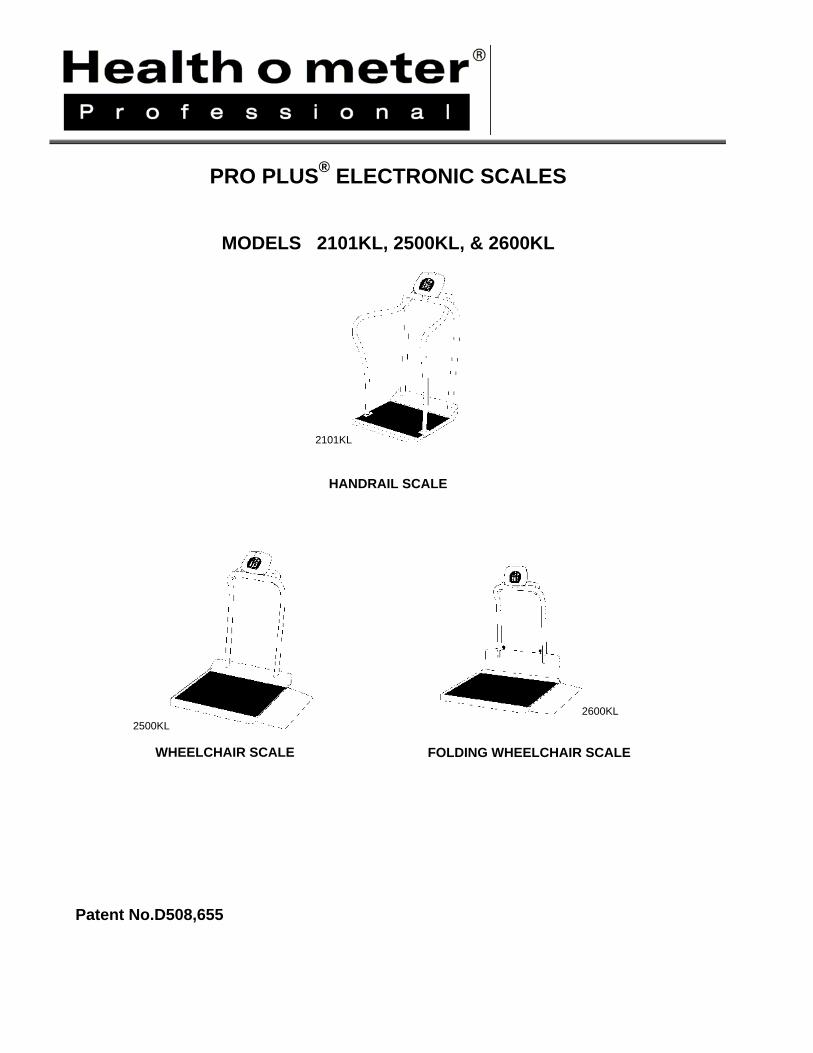
PRO PLUS ® ELECTRONIC SCALES MODELS 2101KL, 2500KL, & 2600KL KL 2101 HANDRAIL SCALE KL 2500 KL 2600 WHEELCHAIR SCALE FOLDING WHEELCHAIR SCALE Patent No.D508,655
Transcript of PRO PLUS ELECTRONIC SCALES
PRO PLUS® ELECTRONIC SCALES
MODELS 2101KL, 2500KL, & 2600KL
KL2101
HANDRAIL SCALE
KL2500 KL2600
WHEELCHAIR SCALE
FOLDING WHEELCHAIR SCALE
Patent No.D508,655

1
OPERATION MANUAL
PROPLUS® ELECTRONIC SCALES
MODELS 2101KL, 2500KL AND 2600KL Thank you for your purchase of this product. Please read this manual carefully and keep it handy for ready reference.
TABLE OF CONTENTS CAUTION AND WARNING....................................................................................................2
SPECIFICATIONS.................................................................................................................2
SET UP..................................................................................................................................3-4
OPERATION INSTRUCTIONS..............................................................................................5-16
MAINTENANCE.....................................................................................................................17
TROUBLESHOOTING...........................................................................................................18
CALIBRATION PATH ............................................................................................................19
EXPLODED VIEW OF DISPLAY MODULE...........................................................................20
DISPLAY MODULE PARTS LIST..........................................................................................20
2101KL EXPLODED VIEW …………………………………………………………………… ..... 21
2101KL PARTS LIST………………………………………………………………………… ........22
2500KL EXPLODED VIEW ………………………………………………………………………..23
2500KL PARTS LIST……………………………………………………………………………… .24
2600KL EXPLODED VIEW …………………………………………………………………… .....25
2600KL PARTS LIST…………………………………………………………………………….....26
COMMUNICATION PROTOCOL……………………………………………………………… ....31
WARRANTY ..........................................................................................................................32

2
CAUTION AND WARNING To prevent injury and damage to your scale, please follow these instructions very carefully.
• Do not transport the scale while the platform is loaded.
• For accurate weighing the scale must be placed on a flat, stable surface.
• For accurate weighing, verify proper operation according to the procedure described in this manual before each use.
• Do not use in the presence of flammable materials.
• Operating at other voltages and frequencies than specified could damage the equipment.
• If the “LOW BAT” indicator activates, for accurate weighing, replace the batteries or connect the scale to an AC power source as soon as possible.
• It is intended that this equipment be used with assistance of a health care worker.
SPECIFICATIONS GENERAL Health o meter’s Pro Plus® Electronic Scales Models 2101KL, 2500KL and 2600KL use highly sophisticated microprocessor technology. Each precision instrument is designed to provide accurate, reliable and repeatable weight measurements and features that make the weighing process simple, fast and convenient. The scale is set up to use motion-sensing weighing technology, to determine the actual weight of a moving patient. The scale may be changed to measure live weight; see page 12 for instructions on changing the scale setting.
The weight can be display in pounds (decimals, fractions of a lb or lb/oz) or in kilograms. The scale features a wrap-around handrail for patient comfort and safety and a 180 degree swivel/pivot head for reading from either side of the scale. Also included on the platform scales (2101KL, 2500KL & 2600KL) are two wheels for easy mobility. The unit can be operated using its AC adapter or by 6-D cell batteries (not included).
3
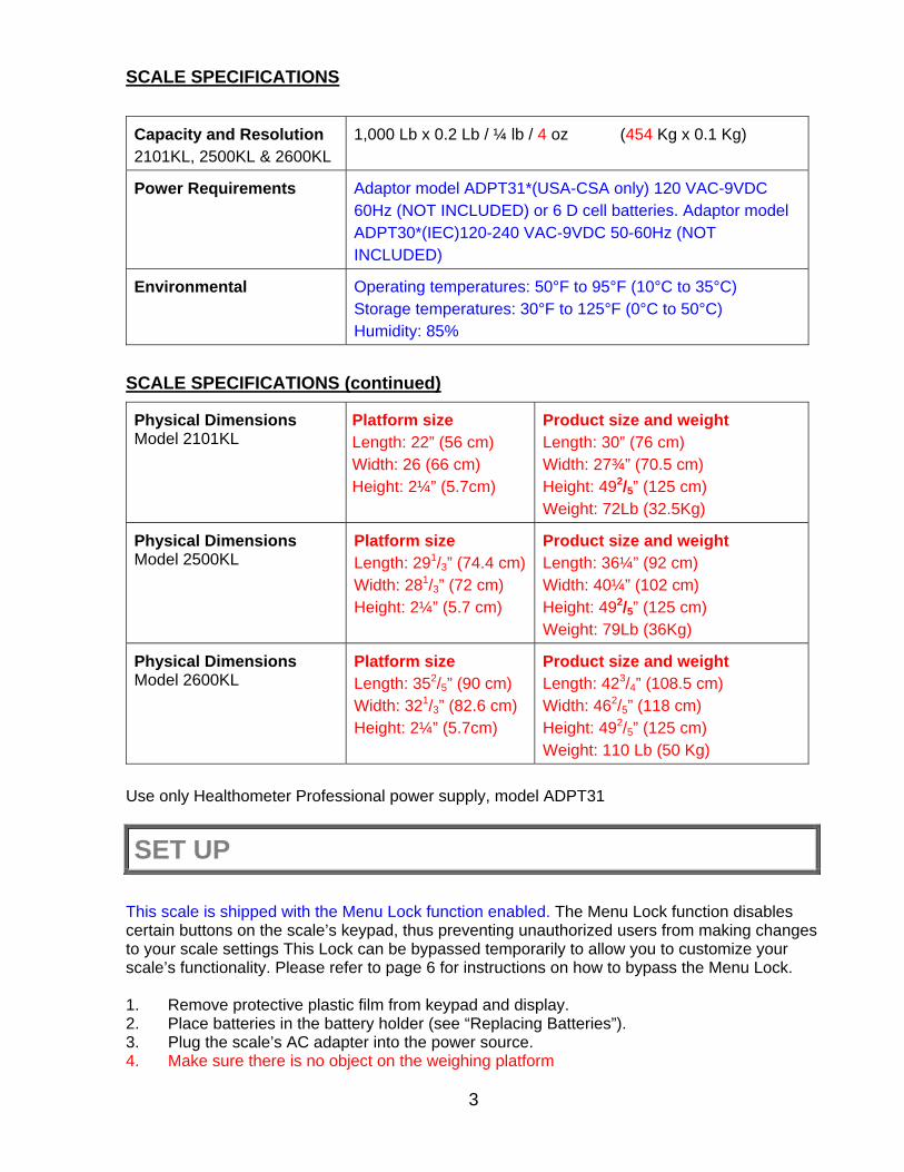
SCALE SPECIFICATIONS
Capacity and Resolution 2101KL, 2500KL & 2600KL
1,000 Lb x 0.2 Lb / ¼ lb / 4 oz (454 Kg x 0.1 Kg)
Power Requirements Adaptor model ADPT31*(USA-CSA only) 120 VAC-9VDC 60Hz (NOT INCLUDED) or 6 D cell batteries. Adaptor model ADPT30*(IEC)120-240 VAC-9VDC 50-60Hz (NOT INCLUDED)
Environmental Operating temperatures: 50°F to 95°F (10°C to 35°C) Storage temperatures: 30°F to 125°F (0°C to 50°C) Humidity: 85%
SCALE SPECIFICATIONS (continued)
Physical Dimensions Model 2101KL
Platform size Length: 22” (56 cm) Width: 26 (66 cm) Height: 2¼” (5.7cm)
Product size and weight Length: 30” (76 cm) Width: 27¾” (70.5 cm) Height: 492/5” (125 cm) Weight: 72Lb (32.5Kg)
Physical Dimensions Model 2500KL
Platform size Length: 291/3” (74.4 cm)Width: 281/3” (72 cm) Height: 2¼” (5.7 cm)
Product size and weight Length: 36¼” (92 cm) Width: 40¼” (102 cm) Height: 492/5” (125 cm) Weight: 79Lb (36Kg)
Physical Dimensions Model 2600KL
Platform size Length: 352/5” (90 cm) Width: 321/3” (82.6 cm) Height: 2¼” (5.7cm)
Product size and weight Length: 423/4” (108.5 cm) Width: 462/5” (118 cm) Height: 492/5” (125 cm) Weight: 110 Lb (50 Kg)
Use only Healthometer Professional power supply, model ADPT31
SET UP
This scale is shipped with the Menu Lock function enabled. The Menu Lock function disables certain buttons on the scale’s keypad, thus preventing unauthorized users from making changes to your scale settings This Lock can be bypassed temporarily to allow you to customize your scale’s functionality. Please refer to page 6 for instructions on how to bypass the Menu Lock. 1. Remove protective plastic film from keypad and display. 2. Place batteries in the battery holder (see “Replacing Batteries”). 3. Plug the scale’s AC adapter into the power source. 4. Make sure there is no object on the weighing platform

4
5. Press the ON/OFF button to turn the scale on. The display will show “Health o Meter Pro Plus” and then ”000Lb00oz”.(a)
6. Place a weight [not to exceed the capacity] on the scale. The display should read “WEIGHING“ until the weight calculation is complete and the weight is displayed.
7. Press the KG/LB button to select the weight mode (Lb/Kg).(b) * 8. Press the REWEIGH button; the scale should perform the weighing process again. 9. Remove the weight from the scale, the scale will return to zero and the display will read
“ZERO” on the left upper side of the screen along with ”000Lb00oz”. 10. Disconnect the scale’s AC adapter from the power source. The scale will shut off. Press
On/Off and the scale will switch to battery power.
NOTE: If the set up procedure failed, refer to the troubleshooting instructions. If the problem is not corrected, refer to qualified service personnel.
(a) To adjust the display backlight and/or contrast, please refer to page 12. (b) To change the display mode in pounds to fractions or decimals, please refer to page 6. Replacing Batteries
Figure 1. Replacing Batteries (refer to the Parts List on page 20 for details on parts followed by # )
1. Unplug the scale. 2. Remove the battery cover from the display assembly. 3. Disconnect battery holder cable connector from the scale-battery connector. 4. Carefully remove the battery holder by sliding it out the display assembly. 5. Replace the batteries with new ones.** 6. Carefully position the battery holder into the display assembly. 7. Connect the battery holder cable connector to the scale-battery connector. 8. Attach the battery cover to the display assembly and install the screw.
** We recommend the use of EVEREADY Energizer® e2TM batteries.

5
OPERATION INSTRUCTIONS 1. Make sure there is no object on the weighing platform 2. Press the ON/OFF button to turn the scale on. 3. Wait until ”000Lb00oz” and “ZERO” on the left side of the display appear. 4. Ask the patient to step on the scale. The display should read “WEIGHING“ until the weight
of the person is displayed. 5. If you wish to reweigh without asking the patient to step off and to step on the scale again,
press the REWEIGH button. 6. Ask the patient to step off the scale.
NOTE: The scale will always default to the settings and units last used.
WARNING: If the scale will not be used for some time, remove batteries to avoid a safety hazard.
Figure 2. Keypad
Health o Meter Pro-Plus

6
ITEM DESCRIPTION FUNCTION
POWER Turns scale ON and OFF.
ZERO Zeros the scale prior to weighing.
HOLD/RELEASE
Holds the value of the weighed object on the display until the button is pressed again to clear the value. Also used to scroll down in the menu.
REWEIGH Allows repeated weighing of the patient without stepping off
the scale.
KG/LB
Toggles between kilograms or pounds. Also used to scroll up in the menu. To activate or deactivate the KG or LB only (Lockout) mode you must press and hold the KG/LB button for 13 seconds. See NOTE Below.
MENU Press and hold for 5 seconds to enter the menu of the scale.
BMI Prompts entry of data to calculate the patient’s Body Mass
Index (BMI).
PRINT Prints patient’s data (if printer is connected to the scale).
ID
Prompts entry of patient’s identification number (ID). This ID will be stored with all the weighing made until it is cleared or a different ID is stored.
TARE
Prompts entry of TARE value that will be deducted from the weight on the platform. Also releases tare weight (returns display to zero).
EXIT Reverts back one step when in the menu and data entry
modes.
ENTER Used to enter commands and values into the scale.
NOTE: The Lockout mode prevents the scale from changing between KG and LB until it is deactivated
MENU
In the menu screen the user can set preferences and/or instruct the scale how to handle stored data. The menu can be navigated using the up and down keys ( ) or by entering the associated menu position number with the keypad. The menu has a “roll-over” way of working: when the user scrolls to the bottom of the menu and presses the down button, it will return to the top of the menu.

7
NOTE: The default mode of the scale is set so the menu option is locked out. If the menu button is pushed before activating the menu option, “MenuLock” will show on the display. To temporarily reactivate the use of the MENU key, press and hold the MENU key for 5 seconds. During the menu access delay, the menu will display “MenuLock”. After 5 seconds, the menu will show on the display and you may begin navigating through the menu.
Figure 3. Main Menu
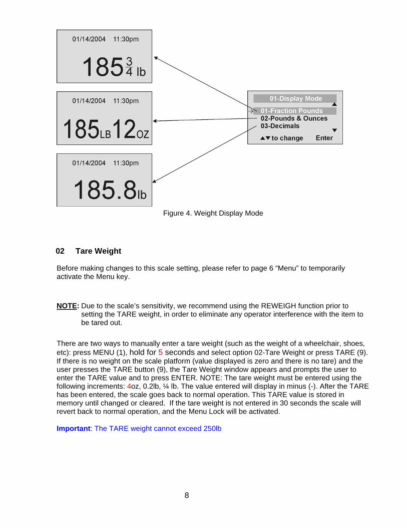
01 WEIGHT DISPLAY MODE (only applies to pound values, NOT the metric values)
Before making changes to this scale setting, please refer to “Menu” instructions above to temporarily activate the Menu key. The user can set the screen display value in either fraction of pound (¼, ½ or ¾ lb), in pounds and ounces (resolution of 4 ounces) or in decimals (resolution of 0.2 lb). When kg is selected as the units of use, these settings have no effect. The mode that is selected is used through all the screens.
▲▼ to change Enter
8
Figure 4. Weight Display Mode
02 Tare Weight
Before making changes to this scale setting, please refer to page 6 “Menu” to temporarily activate the Menu key.
NOTE: Due to the scale’s sensitivity, we recommend using the REWEIGH function prior to setting the TARE weight, in order to eliminate any operator interference with the item to be tared out.
There are two ways to manually enter a tare weight (such as the weight of a wheelchair, shoes, etc): press MENU (1), hold for 5 seconds and select option 02-Tare Weight or press TARE (9). If there is no weight on the scale platform (value displayed is zero and there is no tare) and the user presses the TARE button (9), the Tare Weight window appears and prompts the user to enter the TARE value and to press ENTER. NOTE: The tare weight must be entered using the following increments: 4oz, 0.2lb, ¼ lb. The value entered will display in minus (-). After the TARE has been entered, the scale goes back to normal operation. This TARE value is stored in memory until changed or cleared. If the tare weight is not entered in 30 seconds the scale will revert back to normal operation, and the Menu Lock will be activated. Important: The TARE weight cannot exceed 250lb
9
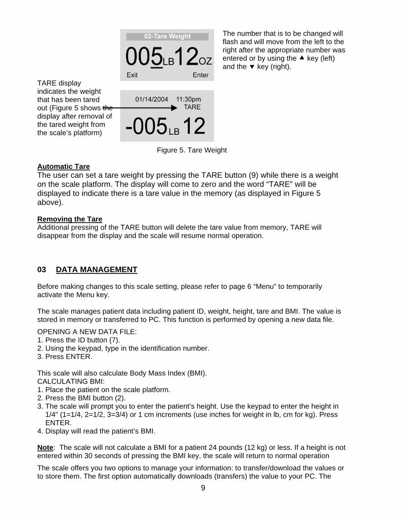
TARE display indicates the weight that has been tared out (Figure 5 shows the display after removal of the tared weight from the scale’s platform)
The number that is to be changed will flash and will move from the left to the right after the appropriate number was entered or by using the key (left) and the key (right).
Figure 5. Tare Weight
Automatic Tare The user can set a tare weight by pressing the TARE button (9) while there is a weight on the scale platform. The display will come to zero and the word “TARE” will be displayed to indicate there is a tare value in the memory (as displayed in Figure 5 above).
Removing the Tare Additional pressing of the TARE button will delete the tare value from memory, TARE will disappear from the display and the scale will resume normal operation.
03 DATA MANAGEMENT
Before making changes to this scale setting, please refer to page 6 “Menu” to temporarily activate the Menu key. The scale manages patient data including patient ID, weight, height, tare and BMI. The value is stored in memory or transferred to PC. This function is performed by opening a new data file.
OPENING A NEW DATA FILE: 1. Press the ID button (7). 2. Using the keypad, type in the identification number. 3. Press ENTER. This scale will also calculate Body Mass Index (BMI). CALCULATING BMI: 1. Place the patient on the scale platform. 2. Press the BMI button (2). 3. The scale will prompt you to enter the patient’s height. Use the keypad to enter the height in 1/4" (1=1/4, 2=1/2, 3=3/4) or 1 cm increments (use inches for weight in lb, cm for kg). Press ENTER. 4. Display will read the patient’s BMI.
Note: The scale will not calculate a BMI for a patient 24 pounds (12 kg) or less. If a height is not entered within 30 seconds of pressing the BMI key, the scale will return to normal operation
The scale offers you two options to manage your information: to transfer/download the values or to store them. The first option automatically downloads (transfers) the value to your PC. The

10
second option stores the value in memory. The maximum capacity of the scale is 270 files of different data.
01 Auto Download
Automatic Download is the default option and will transfer the value to the PC as soon as the patient steps off the scale or when the user presses the HOLD/RELEASE button if it was kept in “HOLD”. If no PC is connected, the value is not transferred and not stored and will be lost after the load is removed from the scale.
02 Store in memory
The value is stored in memory for later download to PC. If the memory is close to full the user will be warned and given the option to transfer all values to the PC or to clear the memory of all values.
03 Do not store data
No data will be stored
▲▼ to change Enter

11
04 Transfer now
All the values stored in memory are transferred to the PC and the scale memory is cleared of all values. If the transfer was unsuccessful, the values are kept in memory until successfully transferred or cleared.
05 Clear memory
If select YES, then press Enter, All the values stored in memory will be cleared. If select NO, then it will return to the last menu.
03 SCALE SETTINGS Before making changes to this scale setting, please refer to page 6 “Menu” to temporarily activate the Menu key.
01 Auto Hold Time
The user can determine how long to display the weight reading once it is determined, regardless of whether the patient remains on the platform. The scale defaults to no Auto Hold Time. The maximum setting is 20 seconds Hold Time.
02 Sleep Time

12
The user can set the time elapsed before the scale goes into the sleep mode. The default is 1 minute. When the scale goes into sleep mode, STANDBY is displayed on the screen. The maximum setting is 10 minutes Sleep Time.
03 Auto Off Time
The user can determine how long the scale will operate before turning off automatically due to inactivity. Default time is 10 minutes. If the value is set to zero, the auto off function is disabled. The maximum setting is 60 minutes Auto Off Time.
04 Tone Volume
There is an option to adjust the beeping tone of the scale. This tone should sound when the scale has determined the weight on the platform, when a key is pressed, after the scale is turned on, at the end of self-test, or in the case of fault or warning. Use the and keys on the keypad to adjust the volume. Whenever the user presses the key to change a volume, a beep will sound to indicate the set volume level.
05 Display Date and Time
This option will turn on or turn off the date and time display.
06 Display Backlight
01:00

13
The user can set the brightness of the backlight.
07 Display Contrast
The user can set the contrast of the LCD.
08 Live Weight
By selecting “Yes” the user can set the Live Weight mode to deactivate the motion-sensing mode. In the Live Weight mode the weight displayed will fluctuate with the patient’s movement; the scale will not lock on to the weight as is the case in the motion-sensing mode. Press the REWEIGH button to operate the motion-sensing mode and to determine the correct weight on the screen. To revert back to motion-sensing mode, change the Live Weight setting to “NO”.
06 SYSTEM SETTINGS
Before making changes to this scale setting, please refer to page 6 “Menu” to temporarily activate the Menu key.

14
01 Set Time & Date The user can set the time and date using the keypad.
To set the time move between hours, minutes and seconds using the up and down keys and enter the values on the keypad. If set Display 24 Hours to YES, do not set AM/PM AM/PM) If set Display 24 Hours to NO, then will jump to the AM/PM line press the ENTER button once.
Set the date using the up and down keys and enter the values on the keypad.
02 About
This screen displays the software version of the scale.
03 Display 24 Hour

15
There are two options display the time: 12 hour (AM/PM) or 24 hour.
06 SYSTEM TEST Before making changes to this scale setting, please refer to page 6 “Menu” to temporarily activate the Menu key.
01 Battery Test
The scale will display the estimated amount of battery life remaining until the batteries will have to be replaced.
NOTE: In order to complete the battery test, the scale must be powered by batteries only. Unplug the scale from AC power source prior to battery test.
02 USB Connection
The scale will test the connection to the PC and will display a message “Connection is OK” or ”NO Connection”. If “NO Connection” is displayed, check your USB connections on the scale and on your PC and retest the connection. Refer to qualified service personnel if problem persists.

16
The scale has a diagnostic routine where it tests the User Interface (UI) hardware functionality (LCD, keypad). In order to do this the user has to press all the keys according to the messages displayed on the screen.
If the requested command was not received or wrong button was pressed, the following message will be displayed.
If after 10 seconds the requested command was not received, the following message will be displayed. If “UI Error Failure” is displayed, refer to qualified service personnel.
07 USER SETTINGS Before making changes to this scale setting, please refer to page 6 “Menu” to temporarily activate the Menu key.
01 Retain Entered Values
This option allows the user to use the same values for ID, height and TARE between weighing. If this option is disabled, the user has to re-enter these values for each reading. If the values are not entered, only the weight is stored. NOTE: These values cannot be retained by ID number.

17
02 Display Height & ID
When the user selects to display the height and ID of the user, it will be displayed at the bottom of the screen. We recommend the use of this function to ensure that the patient’s correct ID and height have been entered.
03 Prompt For Height
When this option is activated, the user will be asked to enter the patient’s height after every weighing. The operator has 30 seconds to enter height.
04 Prompt For ID
When this option is activated, the user will be asked to enter the patient’s ID number after every weighing. The operator has 30 seconds to enter ID.

18
MAINTENANCE GENERAL This section provides instructions for maintenance, cleaning, troubleshooting and operator replaceable parts for Pro Plus® Electronic Scales Models 2101KL, 2500KL and 2600KL. Maintenance operations other than those described in this section should be performed by qualified service personnel. MAINTENANCE Before first use and after periods of non-use, check the scale for proper operation and function. If the scale does not operate correctly, refer to qualified service personnel. 1. Check overall appearance of the total scale for any obvious damage, wear and tear. 2. Inspect AC adapter for cord cracking or fraying or for broken or bent prongs. CLEANING Proper care and cleaning is essential to ensure a long life of accurate and effective operation.
Disconnect the scale from the AC power source. 1. Clean all external surfaces with a clean damp cloth or tissue. Anti-bacterial soap and water
solution may be used. Dry with a clean soft cloth. 2. Do not immerse the scale into cleaning or other liquid solution. 3. Do not use Isopropyl Alcohol or other solutions to clean the display surface.

19
TROUBLESHOOTING Refer to the following instructions to check and correct any failure before contacting service personnel.
SYMPTOM POSSIBLE CAUSE CORRECTIVE ACTION Scale does not turn on 1. Dead Battery
2. Faulty electrical outlet 3. Bad power supply
1. Replace batteries 2. Use a different outlet 3. Replace adapter
Questionable weight or the scale does not zero
1. External object interfering with the scale
1. Remove interfering object from the scale
2. The display did not show ”0.0” before weighing
2. Ask the patient to get off the scale, zero the scale and begin weighing process again
3. Scale is not placed on a level floor
3. Place the scale on a level floor and begin weighing process again
4. Scale is out of calibration 4. Check weight with known weight value
5. Improper Tare 5. Place the item to be tared on the scale. Press REWEIGH. Once the weight of the item is displayed, press TARE. Place the patient and the tared item back on the scale. Press REWEIGH again.
Weighing is performed but the display shows “weigh” and “reweigh” every few seconds; the weighing process takes too long and no weight is displayed.
The patient is not standing still Ask the patient to stand still or you can change to live weight setting
The display shows “Overload” message
The load on the scale exceeds the capacity (1000.0 Lbs)
Remove the excess weight and use the scale according to its limits
The display shows “LOW BAT” message
The batteries are empty Replace batteries according to instructions
The display shows “Sensor ERR ” message
There is a problem with one or more load cells or the load cell cable is disconnected.
Check load cell cable connection at the display and platform assembly ports. If the problem is not corrected, refer to qualified service personnel to replace the defective load cell.
Display shows “MenuLock” when MENU button is pressed
The MENU key has not been activated
Press and hold the MENU button for 5 seconds to activate
20
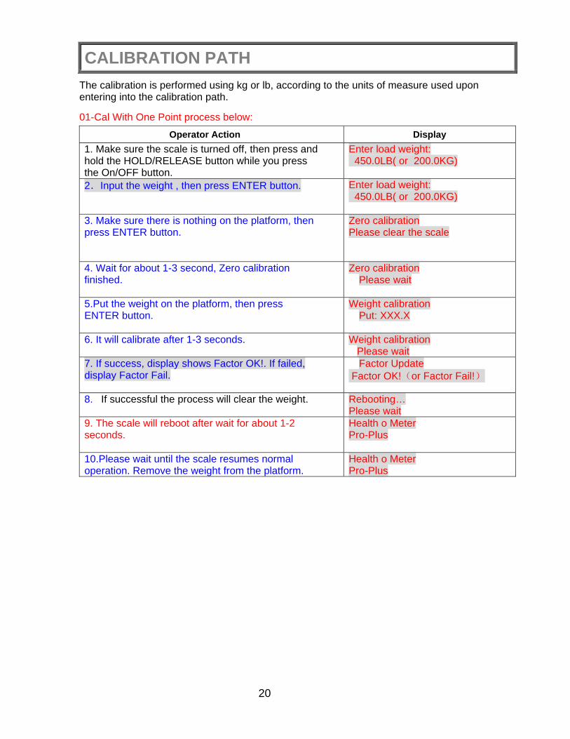
CALIBRATION PATH The calibration is performed using kg or lb, according to the units of measure used upon entering into the calibration path.
01-Cal With One Point process below:
Operator Action Display 1. Make sure the scale is turned off, then press and hold the HOLD/RELEASE button while you press the On/OFF button.
Enter load weight: 450.0LB( or 200.0KG)
2.Input the weight , then press ENTER button.
Enter load weight: 450.0LB( or 200.0KG)
3. Make sure there is nothing on the platform, then press ENTER button.
Zero calibration Please clear the scale
4. Wait for about 1-3 second, Zero calibration finished.
Zero calibration Please wait
5.Put the weight on the platform, then press ENTER button.
Weight calibration Put: XXX.X
6. It will calibrate after 1-3 seconds.
Weight calibration Please wait
7. If success, display shows Factor OK!. If failed, display Factor Fail.
Factor Update Factor OK!(or Factor Fail!)
8. If successful the process will clear the weight.
Rebooting… Please wait
9. The scale will reboot after wait for about 1-2 seconds.
Health o Meter Pro-Plus
10.Please wait until the scale resumes normal operation. Remove the weight from the platform.
Health o Meter Pro-Plus

21
EXPLODED DIAGRAMS
The 2101KL, 2500KL and 2600KL ProPlus® scales all share the same display module. Please refer to page 20 for display module parts for these scales. Exploded diagrams and parts lists are included for the remainder of the scale parts on the pages following the display module parts list.
MODELS 2101KL, 2500KL & 2600KL EXPLODED VIEW OF DISPLAY MODULE
DISPLAY MODULE PARTS LIST – ALL MODELS
Key No. Part No. Description Qty. 31 B411192 KEYPAD 1,000LB 1 32 HEAD TOP 1 33 LCD WINDOW 1 34 LCD BOARD 1 35 WN1412 CROSS HEAD SCREW K22L6 4 36 DISPLAY TO EAGLE P.C.B CABLE 1 37 WN1412 CROSS HEAD SCREW K30L6 4 38 EAGLE BOARD 1 39 HEAD BASE 1 40 PHIL. PAN HEAD SCREW M3.5 6 41 MODEL LABEL 1 42 B3245801-0 INPUT/OUTPUT PORTS LABEL 1 43 PHIL. PAN HEAD SCREW M3 1 44 B3822801-0 BATTERY COVER 1 45 B400152 RUBBER O RING 1 46 B2033801-0 BATTERY HOLDER 1
22
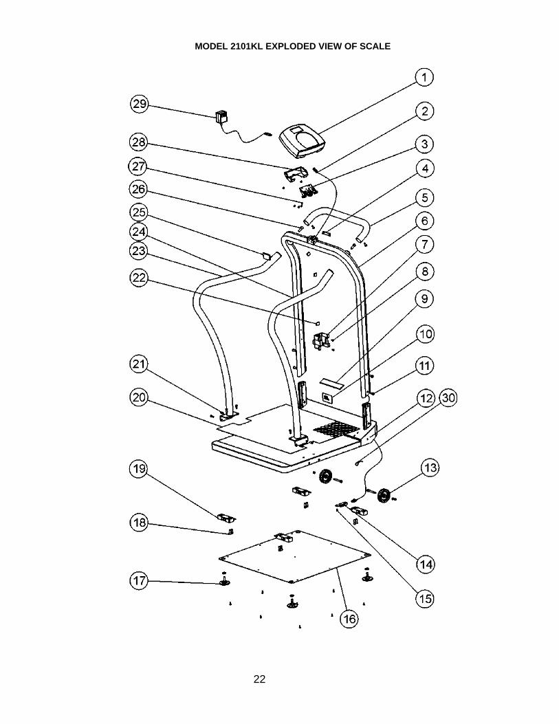
MODEL 2101KL EXPLODED VIEW OF SCALE

23
MODEL 2101KL PARTS LIST
Key No. Part No. Description Qty. 1 B1109401-0 DISPLAY ASSEMBLY 1 2 B2033701-0 MAIN BOARD TO JUNCTION BOX CABLE 1 3 B2266901-0 TILT MECHANISM ASSEMBLY 1 4 B3822601-0 SMALL REAR COVER 1 5 B3822901-0 HANDLE 1 6 B3822101-0 HANDRAIL 1 7 B3817001-0 ADAPTER HOLDER 1 8 SHEET METAL SCREW M3.5 11 9 HEALTH O METER LABEL 1 10 MODEL LABEL 1 11 SOCKET HEAD CAP SCREW M8 4 12 B3822001-0 BASE ASSEMBLY 1 13 B2267201-0 RUBBER WHEEL ASSEMBLY 2 14 B2138901-0 CON. DIG. BOARD 1 15 PHIL. PAN HEAD SCREW M3 1 16 B3822401-0 BOTTOM COVER 1 17 B2266701-0 PLASTIC FOOT M10 ASSEMBLY 4 18 SOCKET HEAD CAP SCREW NC5/16-18*3/4” 8 19 B1304202-0 LOAD CELL 4 20 B3823001-0 PVC MAT 1 21 SOCKET HEAD CAP SCREW M6 10 22 B401305 CABLE CLIP 4 23 LEFT SIDE BAR 1 24 RIGHT SIDE BAR 1 25 B3822501-0 FRONT COVER 1 26 SOCKET HEAD SCREW M10 2 27 PHIL. PAN HEAD SCREW M4 6 28 B3822701-0 REAR COVER 1 29 ADPT31 ADAPTER UNIT 9VDC 120VAC 1 30 CABLE TIE CV100 1

24
MODEL 2500KL EXPLODED VIEW OF SCALE

25
MODEL 2500KL PARTS LIST
Key No. Part No. Description Qty. 1 B1109401-0 DISPLAY ASSEMBLY 1 2 B2033701-0 MAIN BOARD TO JUNCTION BOX CABLE 1 3 B2266901-0 TILT MECHANISM ASSEMBLY 1 4 B3822601-0 BACK BASE COVER 1 5 B3823401-0 HANDRAIL 1 6 B401307 PLASTIC TUBE COVER DIA. 38 2 7 B3817001-0 ADAPTER HOLDER 1 8 SHEET METAL SCREW M3.5 4 9 HEALTH O METER LABEL 1 10 SOCKET HEAD CAP SCREW M8 4 11 CABLE TIE CV100 1 12 B401308 RUBBER BUMPER 2 13 B3823601-0 RIGHT RAMP HINGE 1 14 SPRING LOCK WASHER NC10 8 15 PHIL. PAN HEAD SCREW M5 12 16 B3823501-0 RAMP 1 17 B3823701-0 LEFT RAMP HINGE 1 18 B2138901-0 CON. DIG BOARD 1 19 PHIL. PAN HEAD SCREW M3 1 20 B2266701-0 PLASTIC FOOT M10 ASSEMBLY 4 21 PHIL. PAN HEAD SCREW #8*1/2” 9 22 3823801-0 BOTTOM COVER 1 23 SOCKET HEAD CAP SCREW NC5/16-18*3/4” 8 24 B1304202-0 LOAD CELL 4 25 B2267201-0 RUBBER WHEEL ASSEMBLY 2 26 B3823901-0 GUARDRAIL 1 27 SCALE BASE ASSEMBLY 1 28 B3824101-0 PVC MAT 1 29 MODEL LABEL 1 30 ADPT31 ADAPTER UNIT 9 VDC 120VAC 1 31 B401305 CABLE CLIP 4 32 B3822501-0 BASE COVER 1 33 PHIL. PAN HEAD SCREW M4 6 34 B3822701-0 REAR COVER 1
NOTE: A second Ramp is available separately as 2500RAMP.

26
MODEL 2600KL EXPLODED VIEW OF SCALE View of Scale in Folded Position

27
MODEL 2600KL PARTS LIST
Key No. Part No. Description Qty. 1 B1109401-0 DISPLAY ASSEMBLY 1 2 MAIN BOARD TO JUNCTION BOX CABLE 1 3 TILT MECHANISM ASSEMBLY 1 4 PHIL. PAN HEAD SCREW M4 6 5 B3822701-0 REAR COVER 1 6 B3822601-0 BACK BASE COVER 1 7 B401305 CABLE CLIP 4 8 B3822501-0 BASE COVER 1 9 PLASTIC TUBE COVER DIA. 38 2 10 HEALTH O METER LABEL 1 11 HANDRAIL 1 12 ADPT31 ADAPTER UNIT 9VDC 120VAC 1 13 B3817001-0 ADAPTER HOLDER 1 14 HANDRAIL OPEN RUBBER STOPPER 2 15 HANDRAIL CLOSED RUBBER STOPPER 2 16 B2267601-0 HANDRAIL LOCKING PIN ASSEMBLY 2 17 B3827201-0 HANDRAIL PIVOT 2 18 SOCKET HEAD SHOULDER SCREW 10(M8)*30 2 19 B2267301-0 SWIVEL CASTER 60 ASSEMBLY 2 20 B2267401-0 FIXED CASTER 60 ASSEMBLY 2 21 MODEL LABEL 1 22 B3826901-0 BACK BOX COVER 1 23 B3827001-0 GUARDRAIL 1 24 B2138901-0 CON. DIG BOARD 1 25 PHIL. PAN HEAD SCREW M3 1 26 B1304202-0 LOAD CELL 4 27 SOCKET HEAD CAP SCREW NC5/16-18*3/4” 12 28 B2266701-0 PLASTIC FOOT M10 ASSEMBLY 4 29 PHIL. PAN HEAD SCREW #8*1/2” 32 30 B3823601-0 RIGHT RAMP HINGE 1 31 B3826801-0 BOTTOM COVER 1 32 B401308 RUBBER BUMPER 2 33 B3827401-0 RAMP 1 34 SPRING LOCK WASHER NC10 8 35 PHIL. PAN HEAD SCREW M5 12 36 B3823701-0 LEFT RAMP HINGE 1 37 B401328 SCOTCHMATE LOOP 1 38 B401300 HANDLE 2 39 B3827301-0 BASE 1 40 B3827101-0 PVC MAT 1 41 B401327 SCOTCHMATE HOOK 2 42 SPRING LOCK WASHER M8 4
NOTE: A second Ramp is available separately as 2600RAMP.

28
PC Communication Protocol
This scale uses an escape protocol for communicating with a PC and over the USB and serial port 2(serial port 1 : connecting to the printer). In an Escape protocol, the escape (<esc> or ASCII 27) is used to indicate that there is a command, and not data, following.
Two scenarios have been defined: Scale initiated communication and PC initiated communication. The following is a table of what can be sent across the communications line.
Scale Initiated ESC Value PC Initiated ESC Value Send Single reading R Update Firmware U Send continuousreading
R Request current values/settings
Q
Send bulk readings R Diagnostics A Send scale control messages
C
Request stored data R Set stored data S
Send Diagnostics A
Delete stored data X
The following is a complete list of ESC characters that will be used:
Name ESC
character ESC value with
parameters Description
Reading R R This will tell the PC that the scale is sending a reading. Immediately following this will be the value that is sent (i.e. <ESC>R<ESC>I1234567890<ESC>W200.00<ESC>Nm<ESC>…<ESC>E
ID I Icccccccccc1 This is the patient ID. (10 chars) Weight W Wnnn.nn This is the patient weight (i.e. W200.05 means 200.5 ) Height H Hnnn.nn This is the patient height TARE T Tnnn.nn This is the TARE weight that the scale is taring out BMI B Bnnn.n This is the patient's BMI End Of Packet(EOP)
E E This indicates that the end of the command/datapacket has been reached
Units N Nc This indicates in which unit the values have been taken (m=metric, c=constitutional)
Power Status J J Requests the power status of the scale. The response to this will be either a <ESC>O<ESC>E or <ESC>F<ESC>E or <ESC>L<ESC>E
On O O When prompted for a power status, this will indicate that the scale is turned on
Off F F When prompted for a power status, this will indicate that the scale is turned off (or is in low power/sleep mode) When in Low Power mode, the scale will return L
DateTime D Dnnnnnnnnnnnn
This is a time and date string (MMDDYYYYhhmmss)
Update U Uc This command has a parameter c, which will help doing the update of the firmware. First of all the PC will initiate the update by sending an Ur (Request for update). The scale will reply with Uc (Clear to send) or Ue (error, don’t send). Then the scale will send U127K or U127B (the length of the data that is following in
1 We used descriptive characters to show the type of the parameters. These are: c=Character, n=Numeric. The number of parameters indicates the set number of placeholders for these characters and numbers (i.e. Zccc indicates that a value containing 3 characters will be given.)
29
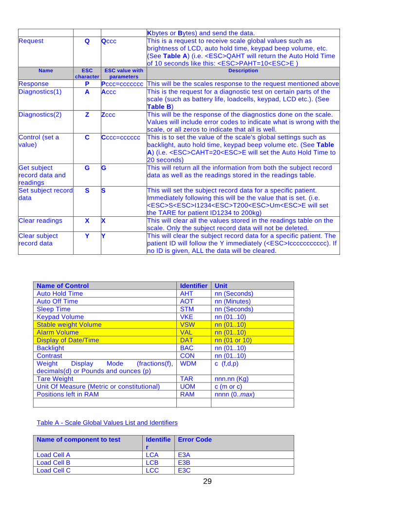
Kbytes or Bytes) and send the data. Request Q Qccc This is a request to receive scale global values such as
brightness of LCD, auto hold time, keypad beep volume, etc. (See Table A) (i.e. <ESC>QAHT will return the Auto Hold Time of 10 seconds like this: <ESC>PAHT=10<ESC>E )
Name ESC character
ESC value with parameters
Description
Response P Pccc=ccccccc This will be the scales response to the request mentioned aboveDiagnostics(1) A Accc This is the request for a diagnostic test on certain parts of the
scale (such as battery life, loadcells, keypad, LCD etc.). (See Table B)
Diagnostics(2) Z Zccc This will be the response of the diagnostics done on the scale. Values will include error codes to indicate what is wrong with the scale, or all zeros to indicate that all is well.
Control (set a value)
C Cccc=cccccc This is to set the value of the scale's global settings such as backlight, auto hold time, keypad beep volume etc. (See Table A) (i.e. <ESC>CAHT=20<ESC>E will set the Auto Hold Time to 20 seconds)
Get subject record data and readings
G G This will return all the information from both the subject record data as well as the readings stored in the readings table.
Set subject record data
S S This will set the subject record data for a specific patient. Immediately following this will be the value that is set. (i.e. <ESC>S<ESC>I1234<ESC>T200<ESC>Um<ESC>E will set the TARE for patient ID1234 to 200kg)
Clear readings X X This will clear all the values stored in the readings table on the scale. Only the subject record data will not be deleted.
Clear subject record data
Y Y This will clear the subject record data for a specific patient. The patient ID will follow the Y immediately (<ESC>Iccccccccccc). If no ID is given, ALL the data will be cleared.
Name of Control Identifier UnitAuto Hold Time AHT nn (Seconds)Auto Off Time AOT nn (Minutes)Sleep Time STM nn (Seconds)Keypad Volume VKE nn (01..10)Stable weight Volume VSW nn (01..10)Alarm Volume VAL nn (01..10)Display of Date/Time DAT nn (01 or 10)Backlight BAC nn (01..10)Contrast CON nn (01..10)Weight Display Mode (fractions(f), decimals(d) or Pounds and ounces (p)
WDM c (f,d,p)
Tare Weight TAR nnn.nn (Kg)Unit Of Measure (Metric or constitutional) UOM c (m or c)Positions left in RAM RAM nnnn (0..max)
Table A - Scale Global Values List and Identifiers
Name of component to test Identifie
rError Code
Load Cell A LCA E3ALoad Cell B LCB E3BLoad Cell C LCC E3C

30
Load Cell D LCD E3DBattery BAT E4L(Bat Low, but still usable) or
E4U (Bat Low and Unstable)PC Communication (USB) PCC E05Write to RAM WRM E08Read from RAM RRM E09Table B - Components to test
The different tables on the scale:
There will be two data tables on the scale. The first will store the subject record data (patient-related data that does not change) and the second will store the data recorded during the readings made.
Subject record data Fields: ID, TARE, HEIGHT Readings Fields: Index (referring to the ID from the Subject Record Table), Weight, Date-time Sample and explanation of esc protocol
1. When the scale measures the weight of a patient and sends this over the communications line to the PC, it will look like this:
<SCALE> <PC>
<ESC>R<ESC>I1234567890<ESC>W90.98<ESC>H178.7<ESC>T5.7<ESC>B28<ESC>Nm<ESCE
2. When the PC requests the values of the stored weighings, it will look like this:
First the PC will ask the scale to send the data. We do this with the “Get Subject Record Data and Readings” command.
<SCALE> <PC>
<ESC>G<ESC>E
Then the scale will reply with the stored data.
Reading (Command)Patient ID = 1234567890Weight = 90.98Height = 178.70TARE = 5.7BMI = 28Unit of measure = MetricEOP
Get subject dataEOP
Direction of communication
Direction of communication

31
<SCALE> <PC>
<ESC>R<ESC>I1234<ESC>W200.19<ESC>H70.5<ESC>B28<ESC>T0.0<ESC>Nm<ESC>R<ESC>I1235<ESC>…<ESC>E
If no data is stored on the scale, it will simply send
<ESC>R<ESC>E
Pin Configuration for ProPlus Cables
The pins of the two connectors are connected as follows:
RJ45 Function DB9 4 TX 2 2 RX 3 1 GND 5
NOTE: Connect the printer cable to the PORT 2 of the scale
NOTE:Transmission Parameters Baud Rate 9600
Parity None Databits 8 bits Stopbits 1bit Startbits 1 bit Hardware handshake None
Direction of communication
1 2 3 4 5 6 7 8
RJ45 DB9
Reading (First patient’s data) Patient ID = 1234 Weight = 200.19 (Pounds) Height = 70.5 (inches)
TARE = 0.0 (Pounds) BMI = 28 Unit of measure = Constitutional Reading (second patient’s data) EOP

32
Printer Parameters
<SCALE> <PRINTER> Pinter model: CT-S280 Working voltage: DC8.5V-2.5A This scale is featured with printing function by connecting the printer XXXXX: 1. Connect the printer cable to the PORT 1 of the scale 2. Turn on the printer power 3. Make sure there is no object on the weighing platform 4.Turn on the scale and wait till display show ZERO and 0.0 before step on the scale 5. Step on the scale and weigh 6. Input the data of patient ID, height, weight of wheelchair and etc. 7. Press 3 (PRINT) key , printer will print out the patient’s ID,weight, height, BMI and etc.
Pin Configuration for ProPlus PrinterCables
RJ45 Function DB9 6 TX 3 7 GND 2
Content from printer as below: 1. ID 2. Weight 3. Height 4. BMI 5. Tare Weight NOTE: Make sure the printer prior for the scale to print it normal NONE: Connect the printer cable to the PORT 1 of the scale
1 2 3 4 5 6 7 8
RJ45DB9
Direction of communication

33
WARRANTY
LIMITED WARRANTY What does the Warranty Cover? Pelstar LLC scales are warranted from date of purchase against defects of materials or in workmanship for a period of three (3) years. If product fails to function properly, return the product, freight prepaid and properly packed to Pelstar. See “To Get Warranty Service” below for instructions. If manufacturer determines that a defect of material or in workmanship exists, customers' sole remedy will be repair or replacement of scale at no charge. Replacement will be made with a new or remanufactured product or component. If the product is no longer available, replacement may be made with a similar product of equal or greater value. All parts including repaired and replaced parts are covered only for the original warranty period. Who is Covered? The original purchaser of the product must have proof of purchase to receive warranty service. Pelstar dealers or retail stores selling Pelstar products do not have the right to alter, or modify or any way change the terms and conditions of this warranty. What is Excluded? Your warranty does not cover normal wear of parts or damage resulting from any of the following: negligent use or misuse of the product, use on improper voltage or current, use contrary to the operating instruction, abuse including tampering, damage in transit, or unauthorized repair or alternations. Further, the warranty does not cover Acts of God, such as fire, flood, hurricanes and tornadoes. This warranty gives you specific legal rights, and you may also have other rights that vary from country to country, state to state, province to province or jurisdiction to jurisdiction. To get Warranty Service Make sure you keep your sales receipt or document showing proof of purchase. Attach proof of purchase to your defective product along with your name, address, daytime telephone number and description of the problem. Carefully package the product and send with shipping and insurance prepaid
If your scale is not covered by warranty, or has been damaged, an estimate of repair costs or replacement costs will be provided to you for approval prior to servicing or replacing.