
Primergy FibreCAT SX40 Storage Subsystem -...
71
Edition December 2006 Primergy FibreCAT SX40 Storage Subsystem Operating Manual Susanne Däschlein Fujitsu Siemens Computers GmbH Paderborn 81730 München e-mail: Internet:[email protected] Tel.: 06001-155 Fax: (++49) 700 / 372 00000 FibreCAT SX40 Sprachen: En
-
Upload
nguyendang -
Category
Documents
-
view
229 -
download
8
Transcript of Primergy FibreCAT SX40 Storage Subsystem -...

Primergy
FibreCAT SX40Storage Subsystem Operating ManualSusanne DäschleinFujitsu Siemens Computers GmbH Paderborn81730 Münchene-mail: Internet:[email protected].: 06001-155Fax: (++49) 700 / 372 00000FibreCAT SX40Sprachen: En
Edition December 2006

Comments… Suggestions… Corrections…The User Documentation Department would like toknow your opinion of this manual. Your feedback helpsus optimize our documentation to suit your individual needs.
Fax forms for sending us your comments are included inthe back of the manual.
There you will also find the addresses of the relevantUser Documentation Department.
Certified documentation according to DIN EN ISO 9001:2000To ensure a consistently high quality standard anduser-friendliness, this documentation was created tomeet the regulations of a quality management system which complies with the requirements of the standardDIN EN ISO 9001:2000.
cognitas. Gesellschaft für Technik-Dokumentation mbHwww.cognitas.de
Copyright and Trademarks
Copyright © 2006 Fujitsu Siemens Computers GmbH.All rights reserved.Delivery subject to availability; right of technical modifications reserved.
All hardware and software names used are trademarks of their respective manufacturers.

FibreCAT SX40 Operating Manual
Contents
1 Introduction . . . . . . . . . . . . . . . . . . . . . . . . . . . 7
1.1 Target Group . . . . . . . . . . . . . . . . . . . . . . . . . . . 8
1.2 Structure of the Manual . . . . . . . . . . . . . . . . . . . . . 8
1.3 Notation Conventions . . . . . . . . . . . . . . . . . . . . . . 9
1.4 Technical Data . . . . . . . . . . . . . . . . . . . . . . . . . 10
2 Important Notes . . . . . . . . . . . . . . . . . . . . . . . . 13
2.1 Notes on Safety . . . . . . . . . . . . . . . . . . . . . . . . 13
2.2 Electrostatic-sensitive Component Label . . . . . . . . . . 15
2.3 CE Certificate . . . . . . . . . . . . . . . . . . . . . . . . . . 16
2.4 RFI Suppression . . . . . . . . . . . . . . . . . . . . . . . . 16
2.5 Notes on Mounting the Rack . . . . . . . . . . . . . . . . . 16
2.6 Notes on Transportation . . . . . . . . . . . . . . . . . . . . 17
2.7 Environmental Protection . . . . . . . . . . . . . . . . . . . 17
3 Operating and Indicator Elements . . . . . . . . . . . . . . 19
3.1 ON/OFF Switch of the Power Supply Units . . . . . . . . . . 19
3.2 Indicator Elements on the Front Side . . . . . . . . . . . . . 193.2.1 Meaning of the Operating Status LEDs . . . . . . . . . . . . . 203.2.2 Meaning of the Status LEDs of the Hard Disk Drives . . . . . . 22
3.3 Indicator Elements on the Rear Side . . . . . . . . . . . . . 233.3.1 Meaning of the Status LEDs of the SAS I/O module . . . . . . 233.3.2 Meaning of the Status LEDs of the Power Supply Units . . . . 25
4 Power Supply . . . . . . . . . . . . . . . . . . . . . . . . . . 27
4.1 Power Supply Units . . . . . . . . . . . . . . . . . . . . . . 274.1.1 Replacing the Power Supply Unit . . . . . . . . . . . . . . . . 28
Operating Manual FibreCAT SX40
Contents
5 Hard Disk Drives . . . . . . . . . . . . . . . . . . . . . . . . 31
5.1 Handling Hard Disk Drives . . . . . . . . . . . . . . . . . . 31
5.2 Removing/Installing Hard Disk Drive/Blank Insert . . . . . . 32
5.3 Hot-Plug for SAS or SATA Hard Disk Drives . . . . . . . . . 36
6 SAS Input/Output Module . . . . . . . . . . . . . . . . . . . 37
6.1 Installing a Second SAS I/O Module . . . . . . . . . . . . . 37
7 Connections . . . . . . . . . . . . . . . . . . . . . . . . . . 39
7.1 SAS Connection . . . . . . . . . . . . . . . . . . . . . . . . 39
7.2 Mains Connection . . . . . . . . . . . . . . . . . . . . . . . 40
8 Configurations . . . . . . . . . . . . . . . . . . . . . . . . . 41
8.1 Basic Configuration . . . . . . . . . . . . . . . . . . . . . . 41
8.2 Redundant Configuration . . . . . . . . . . . . . . . . . . . 42
8.3 Two Node Cluster . . . . . . . . . . . . . . . . . . . . . . . 43
8.4 Two Node Cluster And Redundant Configuration . . . . . . 44
9 Installation . . . . . . . . . . . . . . . . . . . . . . . . . . . 45
9.1 Installation Steps . . . . . . . . . . . . . . . . . . . . . . . 45
9.2 Unpacking the Storage Subsystem . . . . . . . . . . . . . . 46
9.3 Installing the Storage Subsystem in the Rack . . . . . . . . 479.3.1 Requirements of the Rack . . . . . . . . . . . . . . . . . . . . 479.3.2 Installing in the PRIMECENTER Rack . . . . . . . . . . . . . 48
9.4 Switching the Storage Subsystem ON/OFF . . . . . . . . . 53

FibreCAT SX40 Operating Manual
Contents
10 Fault Clearing . . . . . . . . . . . . . . . . . . . . . . . . . 55
10.1 Problem Solutions and Tips . . . . . . . . . . . . . . . . . . 5610.1.1 Power Supply Status LED (Front) . . . . . . . . . . . . . . . . 5610.1.1.1 Power supply status LED remains dark . . . . . . . . . . . . . 5610.1.2 Identification Status LED . . . . . . . . . . . . . . . . . . . . 5610.1.2.1 Identification status LED is on . . . . . . . . . . . . . . . . . . 5610.1.3 Fault Status LED . . . . . . . . . . . . . . . . . . . . . . . . 5610.1.3.1 Fault status LED is on during operation . . . . . . . . . . . . . 5610.1.4 Storage Subsystem Switches OFF . . . . . . . . . . . . . . . 5710.1.5 System does not Start Up after New Drives have been Installed 5710.1.6 Status LED of the Hard Disk Drive does not Come ON . . . . . 5710.1.7 Drives “dead” on System Start . . . . . . . . . . . . . . . . . 5710.1.8 RAID Controller Indicates the Added Drive to be Incorrect . . . 58
Abbreviations . . . . . . . . . . . . . . . . . . . . . . . . . . . . . . . 59
Related Publications . . . . . . . . . . . . . . . . . . . . . . . . . . . 65
Index . . . . . . . . . . . . . . . . . . . . . . . . . . . . . . . . . . . . 67


1 IntroductionThe functionality, mechanics and design of the FibreCAT® SX40 storage subsystem are optimally adapted to the servers of Fujitsu-Siemens Computers. It can be used as rack model. In the 19-inch rack, the FibreCAT® SX40 subsystem occupies two height units.
The FibreCAT® SX40 storage subsystem can accommodate up to twelve 1-inch hard disk drives. If it is equipped, e.g. with twelve 300 Gbyte SAS hard disk drives, approximately 3.6 Tbyte hard disk memory is available within one housing.
The cluster capability is made possible by the use of a second Input/Output module (only available for PRIMEQUEST servers). In conjunction with a cluster-capable operating system, two servers can be run over two channels on a two-channel FibreCAT® SX40 storage subsystem via one HBA (Host Bus Adapter) each.
Server Management/ServerView
(only for connection to PRIMERGY servers and ServerView Suite package)
ServerView and the related agents are set up within the group of servers and storage subsystems being monitored. The received informations are evaluated by ServerView and processed for display or forwarding to the administrator (manager).
I When installing FibreCAT® SX40 storage subsystem in connection with ServerView please install the ServerStart CD version V6.611 or higher on each of the connected servers.
Notes to installing and update see at the documentation of ServerView (see also “Related publications” on page 65).
FibreCAT SX40 Operating Manual 7

Target Group Introduction
1.1 Target Group
The operating instructions are intended for the person responsible for installing the hardware and correctly operating the system. The operating instructions contain all the descriptions which are of importance for commissioning your FibreCAT® SX40 storage subsystem in so far as they do not form part of the publication of your server system.
To understand the different expansion options it is necessary to have a knowledge of hardware and data transmission, as well as basic knowledge of the operating system used.
1.2 Structure of the Manual
The FibreCAT® SX40 storage subsystem manual describes how to install and configure the subsystem and perform expansions or upgrades.
You will find further information in the documentation of your PRIMERGY/PRIMEQUEST server.
This manual consists of the following chapters:
● Important notesThis chapter contains instructions on the safe operation of your storage subsystem as well as information about environmental protection.
● Operating and indicator elementsThis chapter gives a detailed description of the operating panel and the connecting elements on the rear panel of the corresponding storage subsystem.
● Power supplyThis part of the manual describes the power supply units and their power supply. Fitting and removing power supply units is also described in detail.
● Hard disk drivesThis chapter describes in detail how the hot-plug hard disk drives must be dealt with.
● Input/Output moduleThis chapter describes the installing of a second Input/Output module (only available for PRIMEQUEST servers).
8 Operating Manual FibreCAT SX40

Introduction Notation Conventions
● Connections This chapter describes the SAS and the mains connection.
The possibilities of supplying the storage subsystem with mains voltage are also described.
● ConfigurationsThis part of the manual gives configuration examples.
● InstallationThe activities needed to install and commission the storage subsystem are described.
● Clearing faultsThis chapter contains advice on solving problems that occur on commis-sioning or during the operation of the storage subsystem.
1.3 Notation Conventions
Italics identifies commands and entries in flow text
Semibold highlights text
“Quotation marks” indicates references to other chapters or manuals
Ê identifies an operation that you have to perform.
I indicates additional information, notes and tips
V CAUTION! indicates warnings, which, if ignored, will endanger your health, the operability of your server or the security of your data
Table 1: Notation Conventions
FibreCAT SX40 Operating Manual 9

Technical Data Introduction
1.4 Technical Data
Electrical Characteristics
Power supply 2 hot-plug modules with 750 W each (redundant)
Output power 750 W / 1+1each 750 W
Active power maximum 300 W
Apparent power maximum 330 VA
Heat transfer 1080 kJ/h (1024 btu/h)
Rated voltage 100 V - 240 V
Rated current maximum 3 A - 1.5 A / 100 V - 240 V
Rated current in basic configuration 1.9 A - 1 A / 100 V - 240 V
Rated frequency 50 Hz - 60 Hz
Environmental Conditions (according to DIN EN 60721-3-x)
Temperature/operation 10°C to 35°C (to DIN IEC 721)
Noise Development (according to ISO 9296)
LWAd (1 B = 10 dB) IDLE (ISO 7779): 6.4 BOperating (ISO 7779): 6.5 B
LpAm (bystander position) IDLE (ISO 7779): 47 dBOperating (ISO 7779): 47 dB
Dimensions
Rack (H x W x D) 88 x 480 x 582 mm2 height unitsinstallation depth 563 mm
Weight approx. 30 kg (depending on the upgrading)
10 Operating Manual FibreCAT SX40

Introduction Technical Data
Standards Complied With
Product safety
Global IEC 60950
Europe EN 60950, EN 30571
USA UL 60950, CSA 60950
Canada CSA 60950
Electromagnetic compatibility
Europe EN 55022 class A, EN 55024, EN 61000-3-3; EN61000-2-3
Taiwan CNS 13438 class A
Japan VCCI class A
Australia / New Zealand AS/NZ CISPR22 class A
USA / Canada FCC CFR 47 class A /ICES 003 class A
Method of conformity
Europe (CE) 89/336/EWG (EMV), 73/23/EEC (LVD)
North America FCC class A
Admittance
Product safety / Electromagnetic compatibility
Global CB
Europe CE
Germany GS
USA / Canada FCC / CULUS or CCSAUS
Taiwan BSMI
China CCC
Japan VCCI
Russia Ghost
Australia C-Tick
Saudi Arabia SASO
FibreCAT SX40 Operating Manual 11


2 Important Notes
2.1 Notes on Safety
In this section you will find information that you must note when using the storage subsystem.
This device complies with the relevant safety standards for IT equipment.
I The following safety notes are also provided in the “Safety notes and other important information” manual. Also pay attention to the notes in the operating manual of the connected PRIMERGY/PRIMEQUEST system.
If you have any questions relating to setting up and operating your system in the environment where you intend to use it, please contact your sales outlet or our customer service team.
V CAUTION!
● The actions described in these instructions should only be performed by technical specialists. Equipment repairs should only be performed by service personnel. Any unauthorized openings and improper repairs could expose the user to risks (electric shock, energy hazards, fire hazards) and could also damage the equipment. Please note that any unauthorized openings of the device will result in the invalidation of the warranty and exclusion from all liability.
● Transport the device in its original packaging or in other suitable packaging which will protect it against shock or impact.
● Read the notes on environmental conditions in section “Technical Data” on page 10 before setting up and operating the device.
● If the device is brought in from a cold environment, condensation may form both inside and on the outside of the machine.
Wait until the device has acclimatized to room temperature and is absolutely dry before starting it up. Material damage may be caused to the device if this requirement is not observed.
● Check that the rated voltage specified on the type label is the same as the local line voltage.
FibreCAT SX40 Operating Manual 13

Notes on Safety Important Notes
V CAUTION!
● The device must only be connected to a properly grounded wall outlet (the device is fitted with a tested and approved power cable).
● Make sure that the power sockets on the device and the protective grounded outlet of the building’s wiring system is freely accessible.
● Switching off the device does not cut off the supply of power. To do this you must remove the power plugs.
● Before opening the unit, switch off the device and then pull out the power plugs.
● Route the cables in such a way that they do not form a potential hazard (make sure no-one can trip over them) and that they cannot be damaged. When connecting up a device, refer to the relevant notes in this manual.
● Never connect or disconnect data transmission lines during a storm (lightning hazard).
● Systems which comprise a number of cabinets must use a separate fused socket for each cabinet.
● The servers and the directly connected external storage subsystems should be connected to the same power supply distributor. Otherwise you run the risk of losing data if, for example, the central processing unit is still running but the storage subsystem has failed during a power failure.
● Make sure that no objects (such as bracelets or paper clips) fall into or liquids spill into the device (risk of electric shock or short circuit).
● In emergencies (e.g. damage to housings, power cords or controls or ingress of liquids or foreign bodies), immediately power down the device, pull out the power plugs and notify your service department.
● Note that proper operation of the system (in accordance with IEC 60950/DIN EN 60950) is guaranteed only if slot covers are installed on all vacant slots and/or dummies on all vacant bays and the housing cover is fitted (cooling, fire protection, RFI suppression).
14 Operating Manual FibreCAT SX40

Important Notes Electrostatic-sensitive Component Label
2.2 Electrostatic-sensitive Component Label
Electrostatic-sensitive components may be identified by the following sticker:
Figure 1: Electrostatic-sensitive Component Sticker
You must follow the instructions below when handling modules containing electrostatic-sensitive components
Ê Discharge static electricity from your body (for example by touching a grounded metal object) before handling modules containing electrostatic-sensitive components.
Ê The equipment and tools you use must be free of static charge.
Ê Remove the power plug before installing or removing modules containing electrostatic-sensitive components.
Ê Only hold modules containing electrostatic-sensitive components by their edges.
Ê Do not touch any of the pins or track conductors on a module containingelectrostatic-sensitive components.
Ê Use a grounding strap designed for the purpose, to connect you to the system unit as you install the modules.
Ê Place all components on a static-safe base.
I An exhaustive description of the handling of modules containing electro-static-sensitive components can be found in the relevant European and international standards (DIN EN 61340-5-1, ANSI/ESD S20.20).
FibreCAT SX40 Operating Manual 15

CE Certificate Important Notes
2.3 CE Certificate
2.4 RFI Suppression
All other equipment which is connected to this product must also have radio noise suppression in accordance with EC Guideline 89/336/EWG.
Products which meet this requirement are accompanied by a certificate to that effect issued by the manufacturer and/or bear the CE mark. Products which do not meet this requirement may be operated only with the special permission of the BZT (Bundesamt für Zulassungen in der Telekommunikation).
I This is a “Class A“ equipment. This equipment may cause harmful inter-ference in residential areas. In this case, the user may be held liable for taking appropriate measures and bearing the costs resulting from these measures.
2.5 Notes on Mounting the Rack
● For safety reasons, at least two people are required to install the rack-mounted model because of its weight and size.
● When connecting and disconnecting cables, observe the notes in the operating manual of your PRIMERGY/PRIMEQUEST system and the comments in the ”Important notes“ chapter in the technical manual supplied with the rack.
● Ensure that the anti-tilt bracket is correctly mounted when you set up the rack.
● For safety reasons, no more than one unit may be withdrawn from the rack at any one time during installation and maintenance work.
The shipped version of this device complies with the requirements of the EEC directives 89/336/EEC ”Electromagnetic compatibility“ and 73/23/EEC ”Low voltage directive“. The device therefore qualifies for the CE certificate (CE=Communauté Européenne).
16 Operating Manual FibreCAT SX40

Important Notes Notes on Transportation
● If more than one unit is withdrawn from the rack at any one time, there is a danger that the rack will tilt forward.
● The power supply to the rack must be installed by an authorized specialist (electrician).
2.6 Notes on Transportation
I Transport the storage subsystem in its original packaging or in other suitable packaging which will protect it against shock or impact.Do not unpack it until all transport maneuvers are completed.
If you need to lift or transport the storage subsystem, ask someone to help you.
2.7 Environmental Protection
Environmentally friendly product design and development
This product has been designed in accordance with standards for ”environmen-tally friendly product design and development“. This means that the designers have taken into account important criteria such as durability, selection of materials, emissions, packaging, the ease with which the product can be dismantled and the extent to which it can be recycled.
This saves resources and thus reduces the harm done to the environment.
Notes on packaging
Please do not throw away the packaging. We recommend that you do not throw away the original packaging in case you need it later for transporting.
Notes on labeling plastic housing parts
Please avoid attaching your own labels to plastic housing parts wherever possible, since this makes it difficult to recycle them.
FibreCAT SX40 Operating Manual 17

Environmental Protection Important Notes
Take-back, recycling and disposal
For details on returning and reuse of devices and consumables within Europe, refer to the “Returning used devices” manual, or contact your Fujitsu Siemens Computers branch office/subsidiary or our recycling centre in Paderborn:
Fujitsu Siemens ComputersRecycling CenterD-33106 Paderborn
Tel. +49 5251 8180-10
Fax +49 5251 8180-15
The device may not be disposed of with household rubbish. This appliance is labelled in accordance with European Directive 2002/96/EC concerning used electrical and electronic appliances (waste electrical and electronic equipment - WEEE).The guideline determines the framework for the return and recycling of used appliances as applicable throughout the EU. To return your used device, please use the return and collection systems available to you. You will find further information on this at www.fujitsu-siemens.com/recycling.
18 Operating Manual FibreCAT SX40

3 Operating and Indicator ElementsThis section describes the position and meaning of the operating and indicator elements on the FibreCAT® SX40 storage subsystem.
3.1 ON/OFF Switch of the Power Supply Units
Each power supply unit has a power switch on the rear side of the FibreCAT® SX40 storage subsystem.
Figure 2: Power Switches
(1) Power switches
3.2 Indicator Elements on the Front Side
You can see the following on the front side of the FibreCAT® SX40 subsystem:
– the four operating status LEDs which indicate the identification, the power supply, the temperature and the fault status
– Status LEDs of the hard disk drives
I There is a “Identification“ and a “Power/Activity/Fault“ LED for each of the 12 possible hard disk drives.
Position Function Description
(I) On The power supply unit is switched on.
(O) Off The power supply unit is switched on.
1 1
FibreCAT SX40 Operating Manual 19
Indicator Elements on the Front Side Operating and Indicator Elements
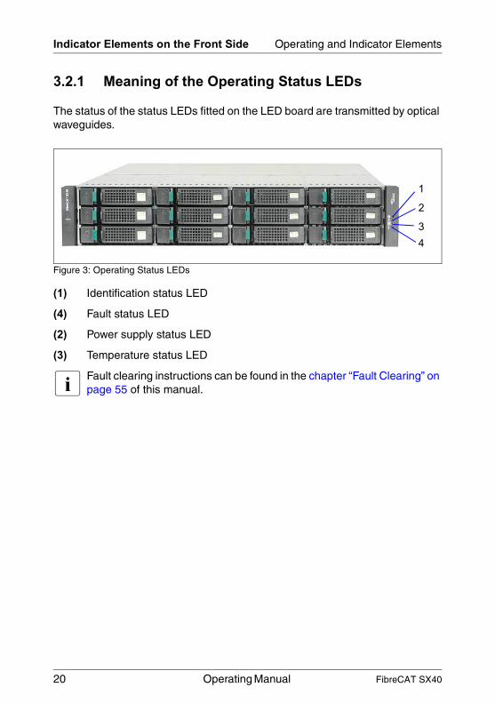
3.2.1 Meaning of the Operating Status LEDs
The status of the status LEDs fitted on the LED board are transmitted by optical waveguides.
Figure 3: Operating Status LEDs
(1) Identification status LED
(4) Fault status LED
(2) Power supply status LED
(3) Temperature status LED
I Fault clearing instructions can be found in the chapter “Fault Clearing” on page 55 of this manual.
1
2
34
20 Operating Manual FibreCAT SX40

Operating and Indicator Elements Indicator Elements on the Front Side
V CAUTION!
The Server Management software (ServerView) reports the exceeding of the temperature limit. The subsystem does not switch off automatically in the case of overheating because data can only be saved to the hard disk drives when the connected server has been shut down properly.
LED Color At power-on Operating Meaning
Identifi-cation status
White On for 3-4 seconds, off
Off Not active
Blinking Identification
Fault status
Yellow On for 3-4 seconds, off
Off No fault
On A fault has occurred. Service action is required. The event has been acknowledged but the problem still needs attention.
Power supply status
Green On for 3-4 seconds, blinking for up to 2 seconds during boot, on
On System is powered on with at least on power supply unit operating normally.
Off Both power supply units are off.
Tem-perature status
Green On for 3-4 seconds, off
Off The inside temperature is normal.
Yellow On The inside temperature is above treshold.
FibreCAT SX40 Operating Manual 21
Indicator Elements on the Front Side Operating and Indicator Elements
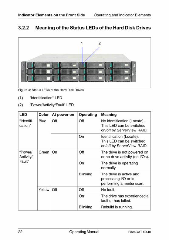
3.2.2 Meaning of the Status LEDs of the Hard Disk Drives
Figure 4: Status LEDs of the Hard Disk Drives
(1) “Identification“ LED
(2) “Power/Activity/Fault“ LED
LED Color At power-on Operating Meaning
“Identifi-cation“
Blue Off Off No identification (Locate).This LED can be switched on/off by ServerView RAID.
On Identification (Locate).This LED can be switched on/off by ServerView RAID.
“Power/Activity/ Fault“
Green On Off The drive is not powered on or no drive activity (no I/Os).
On The drive is operating normally.
Blinking The drive is active and processing I/O or is performing a media scan.
Yellow Off Off No fault.
On The drive has experienced a fault or has failed.
Blinking Rebuild is running.
1 2
22 Operating Manual FibreCAT SX40
Operating and Indicator Elements Indicator Elements on the Rear Side
3.3 Indicator Elements on the Rear Side
You can see the following on the rear side of the FibreCAT® SX40 subsystem:
– Status LEDs of the SAS I/O module
– Status LEDs of the hard disk drives
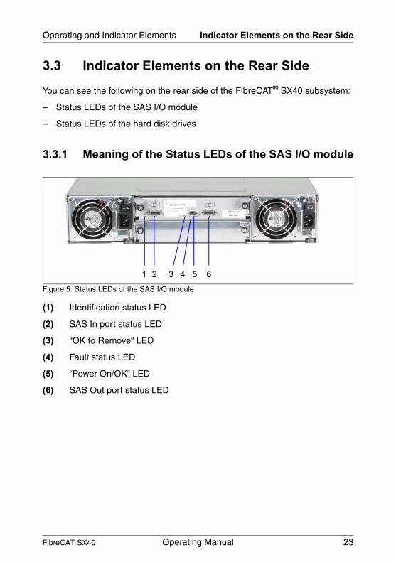
3.3.1 Meaning of the Status LEDs of the SAS I/O module
Figure 5: Status LEDs of the SAS I/O module
(1) Identification status LED
(2) SAS In port status LED
(3) “OK to Remove“ LED
(4) Fault status LED
(5) “Power On/OK“ LED
(6) SAS Out port status LED
1 2 3 4 5 6
FibreCAT SX40 Operating Manual 23

Indicator Elements on the Rear Side Operating and Indicator Elements
LED Color Status Meaning
Identifi-cation status
White Off Not active
Blinking Identification
SAS In port status
Green Off The SAS In port is empty or the link is down.
On The port link is up and connected.
“OK to Remove“
Blue Off Not implemented.
Fault status
Yellow On A fault has occurred. Service action is required.
Blinking Indicates a hardware-controlled power-up or a cache flush or a restore error.
„Power On/OK“
Green Off The SAS I/O module is not okay
On The SAS I/O module is operating normally.
SAS Out port status
Green Off The SAS Out port is empty or the link is down.
On The port link is up and connected.
24 Operating Manual FibreCAT SX40

Operating and Indicator Elements Indicator Elements on the Rear Side
3.3.2 Meaning of the Status LEDs of the Power Supply Units
Figure 6: Status LEDs of the Power Supply Units
(1) “AC Power Good“ LED
(2) “DC Fan Fault“ LED
LED Color Status Meaning
“AC Power Good“
Green Off AC power is off or input voltage is below the minimum threshold.
On AC power is on and input voltage is normal.
“DC Fan Fault“
Yellow Off DC output voltage is normal.
On DC output voltage is out of range or a PSU fan is operating below the minimum required RPM.
1
21
2
FibreCAT SX40 Operating Manual 25


4 Power Supply
4.1 Power Supply Units
The FibreCAT® SX40 storage subsystem contains two power supply units that guarantee the power supply to all the fitted components. If one power supply unit fails, the system will carry on running (redundant power supply).
Figure 7: FibreCAT® SX40 Storage Subsystem with two Power Supply Units
The power supply units are supplied with mains voltage via the supplied connecting leads.
The two power supply units can be connected directly to two different phases of the in-house circuit in order to achieve phase redundancy (see section “Mains Connection” on page 40).
FibreCAT SX40 Operating Manual 27

Power Supply Units Power Supply
4.1.1 Replacing the Power Supply Unit
V CAUTION!
It is imperative that you read the chapter chapter “Important Notes” on page 13 in this manual before you carry out work on your storage subsystem.
If faults occur with the power supply unit, it could be necessary to replace a power supply unit. Information about the relevant error messages can be found in the sections “Meaning of the Operating Status LEDs” on page 20 and “Meaning of the Status LEDs of the Power Supply Units” on page 25 and in the chapter chapter “Fault Clearing” on page 55.
V CAUTION!
When a power supply unit is replaced in a non-redundant power supply system (only one power supply unit present) the server must be switched off or the SAS channels deactivated.
Ê If only one power supply unit is present, shut down the server and switch it off.
Ê Remove the lead of the defective power supply unit.
Figure 8: Power Supply Unit Removed
Ê Loosen the knurled screw.
Ê Pull the lever downward. The power supply unit will be pulled out of the bay a few centimeters by the lever.
Ê Take the power supply unit out of the bay.
28 Operating Manual FibreCAT SX40

Power Supply Power Supply Units
Ê Push the new power supply unit into the empty bay until the lever fits in the bottom of the housing.
Ê Push the lever upward until the power supply unit fits fully in the bay.
Ê Tighten the knurled screw to protect the lever against unintended opening.
Ê Connect the lead to the power supply unit (see the section “Mains Connection” on page 40).
Ê Connect the power cable to the mains (see the section “Mains Connection” on page 40).
FibreCAT SX40 Operating Manual 29


5 Hard Disk DrivesThe FibreCAT® SX40 storage subsystem can accommodate up to twelve 1-inch hard disk drives. If it is equipped, e.g. with twelve 300 Gbyte SAS hard disk drives, approximately 3.6 Tbyte hard disk memory is available as a maximum within one housing.
The SAS or SATA hard disk drives are built into a frame which allows defective hard disk drives to be replaced (hot-plug) or new hard disk drives to be added during operation.
The “hot-plug“ function can only be performed together with a corresponding RAID configuration. Further information about the RAID configuration or RAID level can be found in the disk array controller documentation.
A hard disk drive may only be replaced if it is inactive (see description of the LEDs in the section “Meaning of the Status LEDs of the Hard Disk Drives” on page 22) or has been marked as defective in the management tool.
The hot -plug procedure increases the availability of the system operation and guarantees a high degree of data integrity and protection against failure.
5.1 Handling Hard Disk Drives
Hard disk drives are highly sensitive electromagnetic devices and must be handled with great care. It is extremely likely that an incorrect handling will lead to a partially and/or total failure of the hard disk drives.
These failures will result in data errors and to loss of data or to total destruction of the hard disk drive.
Please observe following rules, which will help to avoid the occurrence of this type of problems:
● Store and transport hard disk drives only within the limits stipulated in the specification.
● When transporting hard disk drives (even over short distances), always use the original packaging (ESD labeling).
● Never expose a hard disk drive to a temperature shock. Avoid the formation of condensation inside and on the outside of the hard disk drives.
FibreCAT SX40 Operating Manual 31

Removing/Installing Hard Disk Drive/Blank Insert Hard Disk Drives
The hard disk drives may be exposed only to defined temperature and climatic conditions.
● Always put the hard disk drive down carefully, with its largest surface facing downwards, to avoid the danger of tipping over.
5.2 Removing/Installing Hard Disk Drive/Blank Insert
V CAUTION!
Under no circumstances should you remove a hard disk drive while the system is in operation if you are not sure that the hard disk drive is operated by a RAID controller and belongs to a disk array which is operating in RAID level 1, 5, 10 or 50.The hard disk drives must all be marked clearly so that they can be put back into the original bays after an upgrade. If this is not taken into account, existing data can be destroyed.
The hard disk drives which can be ordered for the FibreCAT® SX40 storage subsystem are delivered pre-installed in frames. Only a service technician may Removing a hard disk drive from the frame may only be done in authorised repair centers.
Figure 9: Hard Disk Drive in Frame
32 Operating Manual FibreCAT SX40
Hard Disk Drives Removing/Installing Hard Disk Drive/Blank Insert
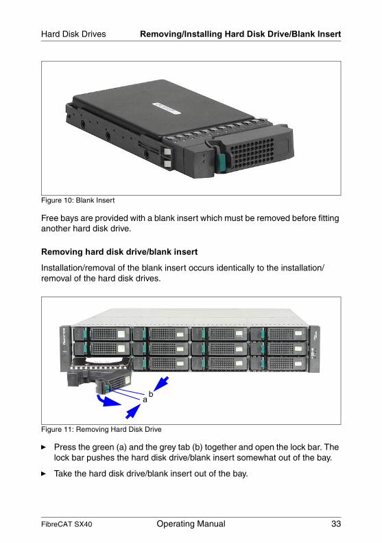
Figure 10: Blank Insert
Free bays are provided with a blank insert which must be removed before fitting another hard disk drive.
Removing hard disk drive/blank insert
Installation/removal of the blank insert occurs identically to the installation/ removal of the hard disk drives.
Figure 11: Removing Hard Disk Drive
Ê Press the green (a) and the grey tab (b) together and open the lock bar. The lock bar pushes the hard disk drive/blank insert somewhat out of the bay.
Ê Take the hard disk drive/blank insert out of the bay.
a b
FibreCAT SX40 Operating Manual 33

Removing/Installing Hard Disk Drive/Blank Insert Hard Disk Drives
V CAUTION!
Keep the blank insert for future use. If you remove the hard disk drive again and do not fit a replacement, you must put back the blank insert because of cooling, adherence to EMC (electromagnetic compatibility) requirements and fire protection.
Installing hard disk drives/blank insert
V CAUTION!
The hard disk drive must be acclimatized in its operating environment for an acclimatization time.
Figure 12: Opening the Lock Bar
Ê Press the green and the grey tab together and open the lock bar (see also figure 11).
Temperature difference (°C)(operating environment/outside)
Minimum acclimatization time (hours)
5 310 515 720 825 930 10
Table 2: Acclimatization Time for the Hard Disk Drives
34 Operating Manual FibreCAT SX40

Hard Disk Drives Removing/Installing Hard Disk Drive/Blank Insert
Figure 13: Installing the Hard Disk Drive
Ê Push the hard disk drive into the empty bay until it stops.
Ê Push the lock bar completely inward until the locking mechanism engages.
Numbering of the hard disk drives
Figure 14: Numbering of the Hard Disk Drives
0 1 2 3
4 5
11
6 7
8 9 10
FibreCAT SX40 Operating Manual 35

Hot-Plug for SAS or SATA Hard Disk Drives Hard Disk Drives
5.3 Hot-Plug for SAS or SATA Hard Disk Drives
V CAUTION!
Before replacing an hard disk drive: switch on the blue “Identification“ LED (section “Meaning of the Status LEDs of the Hard Disk Drives” on page 22) of the depending hard disk drive by ServerView RAID to ensure the replacing of the correct hard disk drive.
If you want to replace an SAS or SATA hard disk drive during operation, proceed as follows:
Ê If you want to pull out a hard disk drive which is not defective, you must ensure that no reading or writing access to this hard disk drive is possible.
Ê Pull the hard disk drive (defective/not defective) out by a few centimeters.
Ê Wait for at least 60 seconds.
I This period is necessary for the Host Bus Adapter to recognize that a hard disk drive has been pulled out and for the hard disk drive to come to a stop.
Ê Pull the hard disk drive right out.
Ê Insert the new hard disk drive.
When you have removed the hard disk drive and are not fitting any replacement, then fit a blank insert into the blank bay. Ensure that the blank insert engages in the bay correctly.
36 Operating Manual FibreCAT SX40

6 SAS Input/Output ModuleThe cluster capability is made possible by the use of a second Input/Output module (only available for PRIMEQUEST servers). In conjunction with a cluster-capable operating system, two servers can be run over two channels on a two-channel FibreCAT® SX40 storage subsystem via one HBA (Host Bus Adapter) each.
6.1 Installing a Second SAS I/O Module
V CAUTION!
Note the safety instructions and the instructions on the ESD label in chapter “Important Notes” on page 13.
Ê Shut down the server that is connected to the FibreCAT® SX40 storage subsystem, wait until the server is switched off and switch off both power supply units (see also section “ON/OFF Switch of the Power Supply Units” on page 19).
Figure 15: Removing the I/O Module Dummy
Ê Loosen the two knurled screws (1) of the SAS I/O module dummy, press down simultaneously the two metal levers and pull out the SAS I/O module dummy.
V CAUTION!
Keep the SAS I/O module dummy for future use. If you remove the SAS I/O module again and do not fit a replacement, you must put back the SAS I/O module dummy because of cooling, adherence to EMC (electro-magnetic compatibility) requirements and fire protection.
1 1
FibreCAT SX40 Operating Manual 37

Installing a Second SAS I/O Module SAS Input/Output Module
Figure 16: Installing the Second SAS I/O Module
Ê Before installation loosen the two knurled screws on the second SAS I/O module and press down the two metal levers.
Ê Carefully push the SAS I/O module into the empty bay.
Ê Push up the two metal levers and fasten the SAS I/O module with the two knurled screws.
38 Operating Manual FibreCAT SX40

7 ConnectionsIf you would like to put the FibreCAT® SX40 storage subsystem into operation, the SAS and the mains connections must be inserted.
7.1 SAS Connection
The required connections are on the rear panel of the storage subsystem.
Figure 17: SAS Connections
Ê Set up the data connection between the server and the storage subsystem by inserting the plug of the SAS cable coming from the server into the SAS In port connector of the FibreCAT® SX40 storage subsystem.
I Ensure that the plug is screwed securely to the SAS connector. Only in this way can the smooth flow of data between the server and the storage subsystem be guaranteed.
V CAUTION!
You can only use SAS cables with a maximum length of 2 m for connection of the MegaRAID SAS 8344 ELP controller (Order number.: S26361-F3215-E1/L1/E201/L201).
SAS In port SAS Out portDebug port
FibreCAT SX40 Operating Manual 39

Mains Connection Connections
7.2 Mains Connection
Figure 18: Inserting the Power Cables
The storage subsystem is supplied with the mains voltage via the two delivered power cables.
Ê Plug the end of the power cables marked (1) into the port of the power supply unit on the rear panel of the storage subsystem.
Ê Plug the end of the power cables marked (2) into a safety socket on the rack mains socket strip.
V CAUTION!
Ensure that at least one power supply unit of the FibreCAT® SX40 storage subsystem and one power supply unit of the server attached to the subsystem are connected with the same phase.
I In order to set up the mains connection of the storage subsystem with phase redundancy, the two power supply units must be connected to two different phases or to two different circuits of the rack installation.
I Ensure that the safety sockets used to connect the storage subsystem are protected sufficiently by a 16 A or 15 A (USA) automatic cutout.
1
2
40 Operating Manual FibreCAT SX40

8 ConfigurationsV CAUTION!
You can only use SAS cables with a maximum length of 2 m for connection of the MegaRAID SAS 8344 ELP controller (Order number.: S26361-F3215-E1/L1/E201/L201).
8.1 Basic Configuration
Figure 19: Basic Configuration 1
● Server with RAID controller/HBA.
● FibreCAT® SX40 storage subsystem (one-channel version with a maximum of 12 hard disk drives).
Figure 20: Basic Configuration 2
● Server with RAID controller/HBA.
● Up to three FibreCAT® SX40 storage subsystems (each one-channel version with a maximum of 12 hard disk drives).
PRIMERGY/
PRIMEQUEST
Server
RA
ID C
on
tro
lle
r/H
BA
FibreCAT SX40
FibreCAT SX40
PRIMERGY/
PRIMEQUEST
Server
RA
ID C
ontr
oller/
HB
A
FibreCAT SX40 Operating Manual 41

Redundant Configuration Configurations
8.2 Redundant Configuration
I In this case redundant configuration means: the total data path is redundant. When a HBA, cable or I/O module will fail, although access is possible to the data of the hard disks.
Figure 21: Redundant Configuration
● Only for PRIMEQUEST servers available.
● PRIMEQUEST server with two HBAs.
● Up to three FibreCAT® SX40 storage subsystems (each two-channel version with a maximum of 12 hard disk drives).
PRIMEQUEST
Server
HB
AH
BA
FibreCAT SX40
42 Operating Manual FibreCAT SX40
Configurations Two Node Cluster
8.3 Two Node Cluster
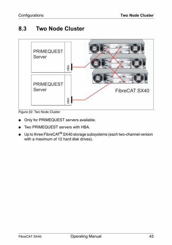
Figure 22: Two Node Cluster
● Only for PRIMEQUEST servers available.
● Two PRIMEQUEST servers with HBA.
● Up to three FibreCAT® SX40 storage subsystems (each two-channel version with a maximum of 12 hard disk drives).
PRIMEQUEST
Server
HB
A
FibreCAT SX40
PRIMEQUEST
Server
HB
A
FibreCAT SX40 Operating Manual 43
Two Node Cluster And Redundant Configuration Configurations
8.4 Two Node Cluster And Redundant Configuration
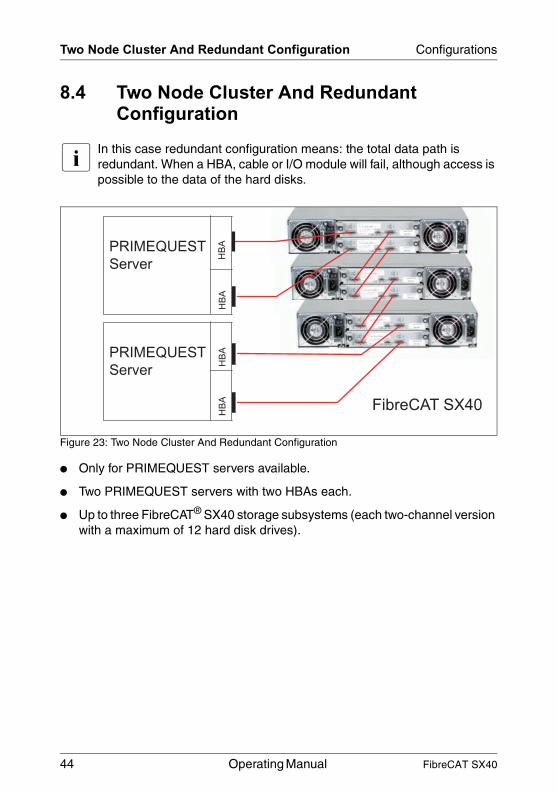
I In this case redundant configuration means: the total data path is redundant. When a HBA, cable or I/O module will fail, although access is possible to the data of the hard disks.
Figure 23: Two Node Cluster And Redundant Configuration
● Only for PRIMEQUEST servers available.
● Two PRIMEQUEST servers with two HBAs each.
● Up to three FibreCAT® SX40 storage subsystems (each two-channel version with a maximum of 12 hard disk drives).
PRIMEQUEST
Server
HB
A
FibreCAT SX40
PRIMEQUEST
Server
HB
AH
BA
HB
A
44 Operating Manual FibreCAT SX40
9 Installation
9.1 Installation Steps
V CAUTION!
The storage subsystem should not be subjected to any extreme environ-mental conditions (see section “Technical Data” on page 10). Protect it from dust, moisture and heat.
The following installation steps are described in detail in other sections of this chapter:
Ê Unpacking the storage subsystem.
Ê Inserting the storage subsystem into the rack.
Ê Cabling the storage subsystem (see section “SAS Connection” on page 39).
Ê Setting the desired system parameters.
Ê Connecting the storage subsystem to the mains voltage (see section “Mains Connection” on page 40).
Ê Switching ON the storage subsystem.
FibreCAT SX40 Operating Manual 45
Unpacking the Storage Subsystem Installation
9.2 Unpacking the Storage Subsystem
V CAUTION!
Please note the safety instructions in chapter “Important Notes” on page 13.
Enlist the help of others to carry the storage subsystem.
You should retain the original packing of the storage subsystem for possible further transport.
Ê Unpack all parts.
Ê Check the contents of the package for visible transport damage.
Ê Check whether the delivery matches the information given on the delivery note.
Ê Check whether the first page of the guarantee booklet has been completed in full.
If you find transport damage or inconsistencies between the contents of the package and the delivery note, inform your supplier immediately!
46 Operating Manual FibreCAT SX40

Installation Installing/Uninstalling the Subsystem in/from the Rack
9.3 Installing the Storage Subsystem in the Rack
V CAUTION!
● Please observe the safety precautions and references to mounting into the rack in chapter “Important Notes” on page 13.
● At least two people are needed to position the server in the rack.
● The rack can tip over if more than one unit is removed.
9.3.1 Requirements of the Rack
The rack systems of the Fujitsu Siemens Computers GmbH (e.g. PRIMECENTER Rack) fully support the installation of the subsystem. For the installation in 3rd-Party racks, please ask your customer service.
To accommodate the ventilation concept and ensure proper ventilation of the components in the rack, any unused areas must be closed using dummy covers.
Power is supplied via the socket strips available in the rack.
The mounting of the cable management is described in detail in the Technical Manual for the respective rack.
The mounting of the cable management is described in detail in the Technical Manual for the respective rack.
FibreCAT SX40 Operating Manual 47

Installing in the Different Racks Installation
9.3.2 Installing in the PRIMECENTER Rack
For installation in the PRIMECENTER Rack, the rack mounting kit delivered with the subsystem is used.
Figure 24: Rack Mounting Kit
1 Sliding rail front right
2 Sliding rail front left
3 Screws and cage nuts
4 Mounting instruction
1 2 3 4
48 Operating Manual FibreCAT SX40
Installation Installing in the Different Racks
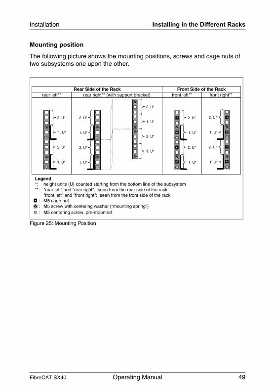
Mounting position
The following picture shows the mounting positions, screws and cage nuts of two subsystems one upon the other.
Figure 25: Mounting Position
Rear Side of the Rack Front Side of the Rackrear left** rear right** (with support bracket) front left** front right**
Legend*: height units (U) counted starting from the bottom line of the subsystem**: "rear left" and "rear right": seen from the rear side of the rack
"front left" and "front right": seen from the front side of the rack: M5 cage nut: M5 screw with centering washer (“mounting spring”)
2. U*
1. U*
2. U*
1. U*
1. U*
2. U*
1. U*
2. U*
2. U*
1. U*
2. U*
1. U*
1. U*
2. U*
1. U*
2. U*
2. U*
1. U*
1. U*
2. U*
: M5 centering screw, pre-mounted
FibreCAT SX40 Operating Manual 49

Installing in the Different Racks Installation
Figure 26: Installing the Support Bracket
For mounting the left sliding rail in the PRIMECENTER rack, the delivered support bracket must first be mounted on the rear left support upright. The bracket must be mounted level with the lower edge of the device.
Ê Refer to the assembly instructions in the Technical Manual for the PRIMECENTER rack (see also “Related publications” on page 65).
I For better orientation the height units are marked on the support uprights.
Ê Mount the support angle at the appropriate height on the left rear support upright as described in the Technical Manual of the PRIMECENTER rack.
50 Operating Manual FibreCAT SX40
Installation Installing in the Different Racks
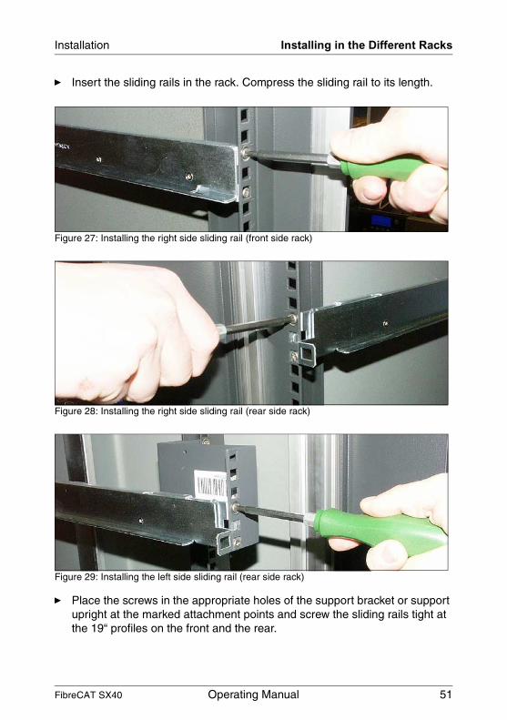
Ê Insert the sliding rails in the rack. Compress the sliding rail to its length.
Figure 27: Installing the right side sliding rail (front side rack)
Figure 28: Installing the right side sliding rail (rear side rack)
Figure 29: Installing the left side sliding rail (rear side rack)
Ê Place the screws in the appropriate holes of the support bracket or support upright at the marked attachment points and screw the sliding rails tight at the 19“ profiles on the front and the rear.
FibreCAT SX40 Operating Manual 51

Installing in the Different Racks Installation
Figure 30: Position of the cage nuts
Ê Place the cage nuts for fastening the subsystem in the appropriate holes of the front support uprights.
Ê Put the subsystem on the support angles of the sliding rails and push the subsystem into the rack as far as it will go.
The following steps can be performed by a single person:
Figure 31: Fastening the Subsystem
Ê Pull off the covers of the fastening angles on both sides.
Ê Secure the subsystem within the rack using two screws on each side.
Ê Install on both sides the covers of the fastening angles.
52 Operating Manual FibreCAT SX40

Installation Switching the Subsystem ON/OFF
Ê Route the cables as described in the Technical Manual of the PRIMECENTER Rack.
9.4 Switching the Storage Subsystem ON/OFF
The FibreCAT® SX40 storage subsystem can be switched on or off via the two power supply switches.
V CAUTION!
If the storage subsystem is not switched on by a connected server, the two power supply units of the storage subsystem must always be switched on before the connected server.
FibreCAT SX40 Operating Manual 53


10 Fault ClearingV CAUTION!
Please note the safety instructions in chapter “Important Notes” on page 13.
If a fault occurs, attempt to rectify it in accordance with the measures set out below:
● Which are described in this chapter,
● Which are described in the documentation for the connected server and the RAID controller or HBA used.
If you cannot rectify the fault, proceed as follows:
Ê Note the steps that you have performed and the state which was active when the error occurred. Note also any error message which may have been displayed.
Ê Switch OFF the connected server.
Ê Switch OFF the power supply units of the storage subsystem and pull out the power plugs.
Ê Contact our service organization.
FibreCAT SX40 Operating Manual 55

Problem Solutions and Tips Fault Clearing
10.1 Problem Solutions and Tips
The following sections describe irregularities which can be observed on the storage subsystem in case of faults. Their possible causes are named and there are instructions for fault clearing.
10.1.1 Power Supply Status LED (Front)
If the power supply status LED is green the device is switched on and the power supply and at least one power supply unit are OK.
10.1.1.1 Power supply status LED remains dark
Power cable not connected correctly
Ê Ensure that the power cable on the storage subsystem and the safety socket are connected correctly.
Power supply units defective
Ê Check the LEDs of the power supply units.
If the “AC Power Good“ LED (green LED) is dark on the power supply units and the “DC Fan Fault“ LED (yellow LED) is on, the power supply units are defective.
Ê Replace the power supply units.
10.1.2 Identification Status LED
10.1.2.1 Identification status LED is on
ServerView switched on this LED for identification. No error.
10.1.3 Fault Status LED
10.1.3.1 Fault status LED is on during operation
ServerView detected a fault, service action is required.
56 Operating Manual FibreCAT SX40
Fault Clearing Problem Solutions and Tips
10.1.4 Storage Subsystem Switches OFF
Temperature too high
The temperature sensors have measured an extreme temperature (tolerable temperature for operation see section “Technical Data” on page 10) and the server has shut down the system.
Ê Wait until the storage subsystem has cooled down.
10.1.5 System does not Start Up after New Drives have been Installed
SAS configuration incorrect (RAID controller)
Ê Call up the configuration menu and check the drive settings (device config-uration) and the additional settings (advanced configuration options).
10.1.6 Status LED of the Hard Disk Drive does not Come ON
Ê Check whether the hard disk drive has been correctly installed and locked (see section “Removing/Installing Hard Disk Drive/Blank Insert” on page 32).
Hard disk drive or SAS/SATA backplane is defective
Ê Replace the hard disk drive. If the status LED is still OFF, the SAS/SATA backplane is defective. Contact the service organization.
10.1.7 Drives “dead” on System Start
Incorrect cabling
Ê Ensure that the cabling correspond to the original status.
FibreCAT SX40 Operating Manual 57

Problem Solutions and Tips Fault Clearing
Configuration of the RAID controller incorrect
Ê Call up the RAID utility from the configuration disk or from the controller BIOS of the RAID controller, and correct the settings for the drives.
You will find further notes in the RAID controller documentation.
10.1.8 RAID Controller Indicates the Added Drive to be Incorrect
This error message can have the following cause:
RAID controller not configured for the drive
Installation was occurred with the system switched off.
Ê Configure the RAID controller retroactively for the drive. You will find infor-mation on this topic in the RAID controller documentation
or
Ê Re-install the drive with the system switched ON.If the drive is still found to be incorrect, it must be replaced (see section “Hot-Plug for SAS or SATA Hard Disk Drives” on page 36).
58 Operating Manual FibreCAT SX40

AbbreviationsThe technical terms and abbreviations given below represent only a selection of the full list of common technical terms and abbreviations.
Not all technical terms and abbreviations listed here are valid for the described system board.
ACAlternating Current
ACPIAdvanced Configuration and Power management Interface
ANSIAmerican National Standards Institute
ASR&RAutomatic Server Recovery and Restart
ATAAdvanced Technology Attachment
BBUBattery Backup Unit
BIOSBasic Input Output System
BMCBaseboard Management Controller
CMOSComplementary Metal Oxide Semiconductor
COMCOMmunication port
CPUCentral Processing Unit
FibreCAT SX40 Operating Manual 59

Abbreviations
DDRDouble Data Rate
DIMMDual In-line Memory Module
DIPDual In-line Package
DMIDesktop Management Interface
DRAMDynamic Random Access Memory
ECCError Correction Code
EEPROMElectrical Erasable Programmable Read Only Memory
EFIExtensible Firmware Interface
EMIElectromagnetic interference
EMRLEmbedded RAID Logic
EPROMErasable Programmable Read Only Memory
ESDElectroStatic Discharge
EVRDEnterprise VRD
HPCHot-plug Controller
60 Operating Manual FibreCAT SX40
Abbreviations
HBAHost Bus Adapter
FPCFront Panel Controller
FRUField Replaceable Unit
FSBFront Side Bus
ICEIn Circuit Emulation
IDEIntegrated (intelligent) Drive Electronics
IECInternational Electrotechnical Commission
IMEIntegrated Mirroring Enhanced
IOOPIntelligent Organisation Of PCI
IPMBIntelligent Platform Management Bus
IPMIIntelligent Platform Management Interface
iRMCintegrated Remote Management Controller
ISOInternational Organisation for Standardisation
LANLocal Area Network
FibreCAT SX40 Operating Manual 61
Abbreviations
LEDLight Emitting Diode
MPSMulti Processor Specification
NMINon Maskable Interrupt
OEMOriginal Equipment Manufacturer
OHCIOpen Host Controller Interface
OSOperating System
PCIPeripheral Components Interconnect
PDAPrefailure Detection and Analyzing
PIOProgrammed Input Output
PDBPower Distribution Board
PLDProgrammable Logic Device
PS(U)Power Supply (Unit)
PWMPulse Wide Modulation
PXEPreboot eXecution Environment
62 Operating Manual FibreCAT SX40

Abbreviations
RAIDRedundant Array of Inexpensive Disks
RoHSRestriction of the Use of Certain Hazardous Substances (Waste from Electric and Electronic Equipment, EU Directive)
RoMBRAID on Motherboard
RSBRemote Service Board
RSTReSeT
RTCReal Time Clock
SASSerial Attached SCSI
SATASerial ATA
SCSISmall Computer Systems Interface
SDDCSingle Device Data Correction
SDRAMSynchronous Dynamic Random Access Memory
SELSystem Event Log
SHDGServer Hardware Design Guide
SMBSystem Management Bus
FibreCAT SX40 Operating Manual 63

Abbreviations
SMMServer Management Mode
SMPSymmetrical Multi Processing
UHCIUnified Host Controller Interface
USBUniversal Serial Bus
VGAVideo Graphics Adapter
VRDVoltage Regulator Down
VRMVoltage Regulator Module
WEEEWaste from Electric and Electronic Equipment (EU Directive)
WfMWired for Management
WOLWake up On LAN
64 Operating Manual FibreCAT SX40

Related PublicationsPRIMERGY manuals are available as PDF file on the ServerBooks CD. The ServerBooks CD is part of the PRIMERGY ServerView Suite delivered with each server system.
The current versions of the required manuals can be downloaded free of charge as PDF files from the Internet. The overview page showing the online documen-tation available on the Internet can be found via the URL:http://manuals.fujitsu-siemens.com. For the documentation of the PRIMERGY servers choose the navigation point industry standard servers.
[1] Safety notes and other important information
[2] Ergonomics
[3] Guarantee
[4] Returning used devices
[5] PRIMECENTER Rack Technical Manual
[6] DataCenter Rack Technical Manual
[7] 19” Rack Technical Manual
FibreCAT SX40 Operating Manual 65


Index
AAC power distribution 40acclimatization time 34adhesive labels on plastic casingparts 17
Bblank insert
removing/installing 32blank insert, hard disk drive 34
Ccage nut 50CE label 16cluster 7configurations 41
Ddisposal of equipment 18drive "dead" 57
Eelectrical data 10electromagnetic compatibility 16EMC 34, 37environmental conditions 10environmental protection 17
Hhard disk drive
acclimatization time 34blank insert 34hot-plug 36removing/installing 32
height units 7hot-plug 36
Iindicator elements
operating status LEDs 19status LEDs of the hard disk
drives 19status LEDs of the PSUs 23status LEDs of the SAS I/O
module 23
Llow voltage directive 16
Mmains connection 40manufacturer’s notes 16
Oon/off switch 19operating status LEDs
fault status 20identification status 20meaning 21power supply status 20temperature status 20
Ppacking 17phase redundancy 40plastic casing parts, adhesive
labels 17power supply status LED dark 56power supply unit
redundancy 27replacement 28
power switch 19
FibreCAT SX40 Operating Manual 67

Index
Rradio suppression 16recycling, equipment 18returning, equipment 18
Ssafety instructions 13SAS connection 39SAS I/O module dummy 37ServerView 7spring nut 50status LED hard disk drive does not
come on 57structure of the manual 8support bracket 50system does not start up 57
Uunpacking 46
68 Operating Manual FibreCAT SX40
Comments on FibreCAT SX40Storage Subsystem
FibreCAT SX40
CommentsSuggestionsCorrections
✁
Submitted by
Fujitsu Siemens Computers GmbHUser Documentation81730 MünchenGermany
Fax: (++49) 700 / 372 00000
Internet: [email protected]://manuals.fujitsu-siemens.com


Information on this document On April 1, 2009, Fujitsu became the sole owner of Fujitsu Siemens Compu-ters. This new subsidiary of Fujitsu has been renamed Fujitsu Technology So-lutions.
This document from the document archive refers to a product version which was released a considerable time ago or which is no longer marketed.
Please note that all company references and copyrights in this document have been legally transferred to Fujitsu Technology Solutions.
Contact and support addresses will now be offered by Fujitsu Technology So-lutions and have the format …@ts.fujitsu.com.
The Internet pages of Fujitsu Technology Solutions are available at http://ts.fujitsu.com/... and the user documentation at http://manuals.ts.fujitsu.com.
Copyright Fujitsu Technology Solutions, 2009
Hinweise zum vorliegenden Dokument Zum 1. April 2009 ist Fujitsu Siemens Computers in den alleinigen Besitz von Fujitsu übergegangen. Diese neue Tochtergesellschaft von Fujitsu trägt seit-dem den Namen Fujitsu Technology Solutions.
Das vorliegende Dokument aus dem Dokumentenarchiv bezieht sich auf eine bereits vor längerer Zeit freigegebene oder nicht mehr im Vertrieb befindliche Produktversion.
Bitte beachten Sie, dass alle Firmenbezüge und Copyrights im vorliegenden Dokument rechtlich auf Fujitsu Technology Solutions übergegangen sind.
Kontakt- und Supportadressen werden nun von Fujitsu Technology Solutions angeboten und haben die Form …@ts.fujitsu.com.
Die Internetseiten von Fujitsu Technology Solutions finden Sie unter http://de.ts.fujitsu.com/..., und unter http://manuals.ts.fujitsu.com finden Sie die Benutzerdokumentation.
Copyright Fujitsu Technology Solutions, 2009


![PRIMERGY BX600 Start Guide - Fujitsu Global for this server are stored in the PRIMERGY Startup Disc. Insert the PRIMERGY Startup Disc and click [PRIMERGY Manuals] on the [PRIMERGY](https://static.fdocuments.us/doc/165x107/5aff609a7f8b9a68498fad97/primergy-bx600-start-guide-fujitsu-global-for-this-server-are-stored-in-the-primergy.jpg)

