PRIMERGY BX600 Management Blade Hardware Guide - Fujitsu Global
1
PRIMERGY BX600 Management Blade Hardware Guide
Areas Covered
Before Reading This Manual
This section explains the notes for your safety and conventions used in this manual. Make
sure to read this section.
Chapter 1 About Management Blades
This chapter explains the system features and the component names of Management Blades.
Chapter 2 Installing and Removing Management Blades
This chapter explains how to install/remove Management Blades to the chassis and default
settings.
Chapter 3 Software
This chapter explains the software that can be used in collaboration with Management
Blades.
Chapter 4 Web UI
This chapter explains the Web UI which enables the management and operation of the blade
server system in the Management Blade.
Chapter 5 CLI
This chapter explains the command line interface (CLI) which enables the management/
operation of the blade server system in the Management Blade.
Chapter 6 Technical Information Knowledgebase
This chapter explains the specifications and operational notes of the Management Blade.

2
Before Reading This ManualFor Your Safety
This manual contains important information, required to operate this product safely.
Thoroughly review the information in this manual before using this product. Especially note the points under "Safety Precautions" provided
with the Chassis or Server Blade, and only operate this product with a complete understanding of the material provided.
This manual and "Safety Precautions" should be kept in an easy-to-access location for quick reference when using this product.
Data Backup
To protect data stored in this product (including basic software (OS) and application software), perform backup and other necessary
operations. Note that data protection is not guaranteed when repairs are performed. It is the customer's responsibility to maintain backup
copies in advance.
In case of data loss, Fujitsu assumes no liability for data maintenance or restoration and damages that occur as a result of the data loss for any
reason, except for items covered under warranty.
High Safety
This product is designed, developed and manufactured as contemplated for general use, including without limitation, general office use,
personal use, household use, and ordinary industrial use, but is not designed, developed and manufactured as contemplated for use
accompanying fatal risks or dangers that, unless extremely high safety is secured, could lead directly to death, personal injury, severe physical
damage, or other loss (hereinafter "High Safety Required Use"), including without limitation, nuclear reaction control in nuclear facility,
aircraft flight control, air traffic control, mass transport control, medical life support system, missile launch control in weapon system. You
shall not use this product without securing the sufficient safety required for the High Safety Required Use. If you wish to use this product for
High Safety Required Use, please consult with our sales representatives in charge before such use.
PRIMERGY BX600 Management Blade Hardware Guide
Contents
This manual supports operation of the PRIMERGY BX600 S3 Blade Server System Unit and BX620 S4
Server Blade. For information on the chassis and Server Blade not described in this manual, refer to the
relevant manuals in the Fujitsu PRIMERGY website (http://primergy.fujitsu.com).
Remarks
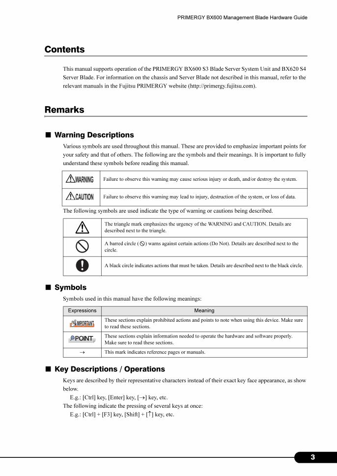
■ Warning Descriptions
Various symbols are used throughout this manual. These are provided to emphasize important points for
your safety and that of others. The following are the symbols and their meanings. It is important to fully
understand these symbols before reading this manual.
The following symbols are used indicate the type of warning or cautions being described.
■ Symbols
Symbols used in this manual have the following meanings:
■ Key Descriptions / Operations
Keys are described by their representative characters instead of their exact key face appearance, as show
below.
E.g.: [Ctrl] key, [Enter] key, [→] key, etc.
The following indicate the pressing of several keys at once:
E.g.: [Ctrl] + [F3] key, [Shift] + [↑] key, etc.
Failure to observe this warning may cause serious injury or death, and/or destroy the system.
Failure to observe this warning may lead to injury, destruction of the system, or loss of data.
The triangle mark emphasizes the urgency of the WARNING and CAUTION. Details are
described next to the triangle.
A barred circle ( ) warns against certain actions (Do Not). Details are described next to the
circle.
A black circle indicates actions that must be taken. Details are described next to the black circle.
Expressions Meaning
These sections explain prohibited actions and points to note when using this device. Make sure
to read these sections.
These sections explain information needed to operate the hardware and software properly.
Make sure to read these sections.
→ This mark indicates reference pages or manuals.
3

4
■ Entering Commands (Keys)
Command entries are displayed in the following way:
• In the spaces indicated with the "↑" mark, press the [Space] key once.
• When using Windows, commands are not case sensitive.
• CD/DVD drive names are shown as [CD/DVD drive]. Enter your drive name according to your
environment.
[CD/DVD drive]:\setup.exe
■ Screen Shots and Figures
Screen shots and figures are used as visual aids throughout this manual. Windows, screens, and file
names may vary depending on the OS, software, or configuration of the server used. Figures in this
manual may not show cables that are actually connected for convenience of explanation.
■ Consecutive Operations
Consecutive operations are described by connecting them with "–".
Example: Procedure of clicking the [Start] button, pointing to [Programs], and clicking [Accessories]
↓
Click [Start] – [All Programs] – [Accessories].
PRIMERGY BX600 Management Blade Hardware Guide
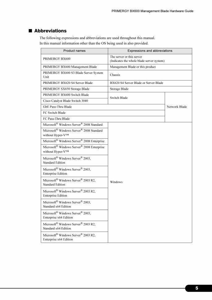
■ Abbreviations
The following expressions and abbreviations are used throughout this manual.
In this manual information other than the OS being used in also provided.
Product names Expressions and abbreviations
PRIMERGY BX600The server or this server
(Indicates the whole blade server system)
PRIMERGY BX600 Management Blade Management Blade or this product
PRIMERGY BX600 S3 Blade Server System
UnitChassis
PRIMERGY BX620 S4 Server Blade BX620 S4 Server Blade or Server Blade
PRIMERGY SX650 Storage Blade Storage Blade
PRIMERGY BX600 Switch BladeSwitch Blade
Network Blade
Cisco Catalyst Blade Switch 3040
GbE Pass-Thru Blade
FC Switch Blade
FC Pass-Thru Blade
Microsoft® Windows Server® 2008 Standard
Windows
Microsoft® Windows Server® 2008 Standard
without Hyper-V™
Microsoft® Windows Server® 2008 Enterprise
Microsoft® Windows Server® 2008 Enterprise
without Hyper-V™
Microsoft® Windows Server® 2003,
Standard Edition
Microsoft® Windows Server® 2003,
Enterprise Edition
Microsoft® Windows Server® 2003 R2,
Standard Edition
Microsoft® Windows Server® 2003 R2,
Enterprise Edition
Microsoft® Windows Server® 2003,
Standard x64 Edition
Microsoft® Windows Server® 2003,
Enterprise x64 Edition
Microsoft® Windows Server® 2003 R2,
Standard x64 Edition
Microsoft® Windows Server® 2003 R2,
Enterprise x64 Edition
5

6
■ Management Blade Firmware
The Web UI/CLI screen configuration and parameters of the Management Blade differ depending on the
firmware version. When referring to manuals, use the manual version that matches the Management
Blade firmware version being used.
This manual describes the Management Blade firmware version V1.62 or later.
Microsoft, Windows and Windows Server are trademarks or registered trademarks of Microsoft Corporation in the United States and other countries. Other product names used are trademarks or registered trademarks of their respective manufacturers. Other products are copyrights of their respective manufacturers.
Copyright FUJITSU LIMITED 2008
Screen shot(s) reprinted with permission from Microsoft Corporation.
PRIMERGY BX600 Management Blade Hardware Guide
Contents
Chapter 1 About Management Blades
1.1 Features . . . . . . . . . . . . . . . . . . . . . . . . . . . . . . . . . . . . . . . . . . . . . 10
1.2 Component Names and Functions . . . . . . . . . . . . . . . . . . . . . . . 11
Chapter 2 Installing and Removing Management Blades
2.1 Before Starting . . . . . . . . . . . . . . . . . . . . . . . . . . . . . . . . . . . . . . . 14
2.2 Installing and Removing . . . . . . . . . . . . . . . . . . . . . . . . . . . . . . . 15
2.3 Default Settings . . . . . . . . . . . . . . . . . . . . . . . . . . . . . . . . . . . . . . 16
2.3.1 Management Software . . . . . . . . . . . . . . . . . . . . . . . . . . . . . . . . . . . . . . . .16
2.3.2 Communication Interface Settings . . . . . . . . . . . . . . . . . . . . . . . . . . . . . . .16
2.3.3 Management User Settings . . . . . . . . . . . . . . . . . . . . . . . . . . . . . . . . . . . .19
2.3.4 Blade Server Time Management . . . . . . . . . . . . . . . . . . . . . . . . . . . . . . . .20
2.3.5 Various Setting Values . . . . . . . . . . . . . . . . . . . . . . . . . . . . . . . . . . . . . . . .21
2.3.6 Points to Note During Management Blade Operations . . . . . . . . . . . . . . .21
Chapter 3 Software
3.1 Software . . . . . . . . . . . . . . . . . . . . . . . . . . . . . . . . . . . . . . . . . . . . 24
Chapter 4 Web UI
4.1 Accessing Web Interface . . . . . . . . . . . . . . . . . . . . . . . . . . . . . . . 26
4.2 Web UI Menu . . . . . . . . . . . . . . . . . . . . . . . . . . . . . . . . . . . . . . . . 27
4.2.1 Start Screen . . . . . . . . . . . . . . . . . . . . . . . . . . . . . . . . . . . . . . . . . . . . . . . .27
4.2.2 Settings Menu . . . . . . . . . . . . . . . . . . . . . . . . . . . . . . . . . . . . . . . . . . . . . .28
4.2.3 System Settings Page . . . . . . . . . . . . . . . . . . . . . . . . . . . . . . . . . . . . . . . .31
4.2.4 System Property Group . . . . . . . . . . . . . . . . . . . . . . . . . . . . . . . . . . . . . . .32
4.2.5 Management Blade Group . . . . . . . . . . . . . . . . . . . . . . . . . . . . . . . . . . . . .48
4.2.6 Lan Switch Blade Group . . . . . . . . . . . . . . . . . . . . . . . . . . . . . . . . . . . . . .49
4.2.7 PHY Module Group . . . . . . . . . . . . . . . . . . . . . . . . . . . . . . . . . . . . . . . . . .50
4.2.8 FC Switch Blade Group . . . . . . . . . . . . . . . . . . . . . . . . . . . . . . . . . . . . . . .51
4.2.9 Adv. KVM Blade Group (when PG-KVB102 is installed) . . . . . . . . . . . . . .52
4.2.10 DKVM Blade Group (when PG-KVB103 is installed) . . . . . . . . . . . . . . .53
4.2.11 Server Blade Group . . . . . . . . . . . . . . . . . . . . . . . . . . . . . . . . . . . . . . . . .55
Chapter 5 CLI
5.1 CLI Connection Methods . . . . . . . . . . . . . . . . . . . . . . . . . . . . . . . 64
5.1.1 Using Serial Interface . . . . . . . . . . . . . . . . . . . . . . . . . . . . . . . . . . . . . . . . .64
5.1.2 Using Telnet via LAN Interface . . . . . . . . . . . . . . . . . . . . . . . . . . . . . . . . . .65
5.2 Basic Operations of Each Screen . . . . . . . . . . . . . . . . . . . . . . . . 66
7
8
5.3 CLI Login . . . . . . . . . . . . . . . . . . . . . . . . . . . . . . . . . . . . . . . . . . . . 67
5.4 CLI Menu . . . . . . . . . . . . . . . . . . . . . . . . . . . . . . . . . . . . . . . . . . . . 69
5.4.1 Console Menu . . . . . . . . . . . . . . . . . . . . . . . . . . . . . . . . . . . . . . . . . . . . . . 69
5.4.2 Management Agent . . . . . . . . . . . . . . . . . . . . . . . . . . . . . . . . . . . . . . . . . 70
5.4.3 Console Redirection . . . . . . . . . . . . . . . . . . . . . . . . . . . . . . . . . . . . . . . . 132
5.4.4 Logout . . . . . . . . . . . . . . . . . . . . . . . . . . . . . . . . . . . . . . . . . . . . . . . . . . . 135
5.4.5 Reboot . . . . . . . . . . . . . . . . . . . . . . . . . . . . . . . . . . . . . . . . . . . . . . . . . . . 135
5.4.6 System Information Dump . . . . . . . . . . . . . . . . . . . . . . . . . . . . . . . . . . . . 136
Chapter 6 Technical Information Knowledgebase
6.1 Specifications . . . . . . . . . . . . . . . . . . . . . . . . . . . . . . . . . . . . . . . 138
6.2 Points to Note about Remote Power OFF and the Shutdown
Function . . . . . . . . . . . . . . . . . . . . . . . . . . . . . . . . . . . . . . . . . . . .139
6.2.1 Remote Power OFF . . . . . . . . . . . . . . . . . . . . . . . . . . . . . . . . . . . . . . . . . 139
6.2.2 Graceful Shutdown Function . . . . . . . . . . . . . . . . . . . . . . . . . . . . . . . . . . 139
6.3 Other Notes . . . . . . . . . . . . . . . . . . . . . . . . . . . . . . . . . . . . . . . . . 140
Chapter 1
About Management Blades
This chapter explains the system features and
the component names of Management Blades.
1.1 Features . . . . . . . . . . . . . . . . . . . . . . . . . . . . . . . . . . . . . 10
1.2 Component Names and Functions . . . . . . . . . . . . . . . . . . 11
9
1
Chapter 1 About Management Blades
1.1 Features
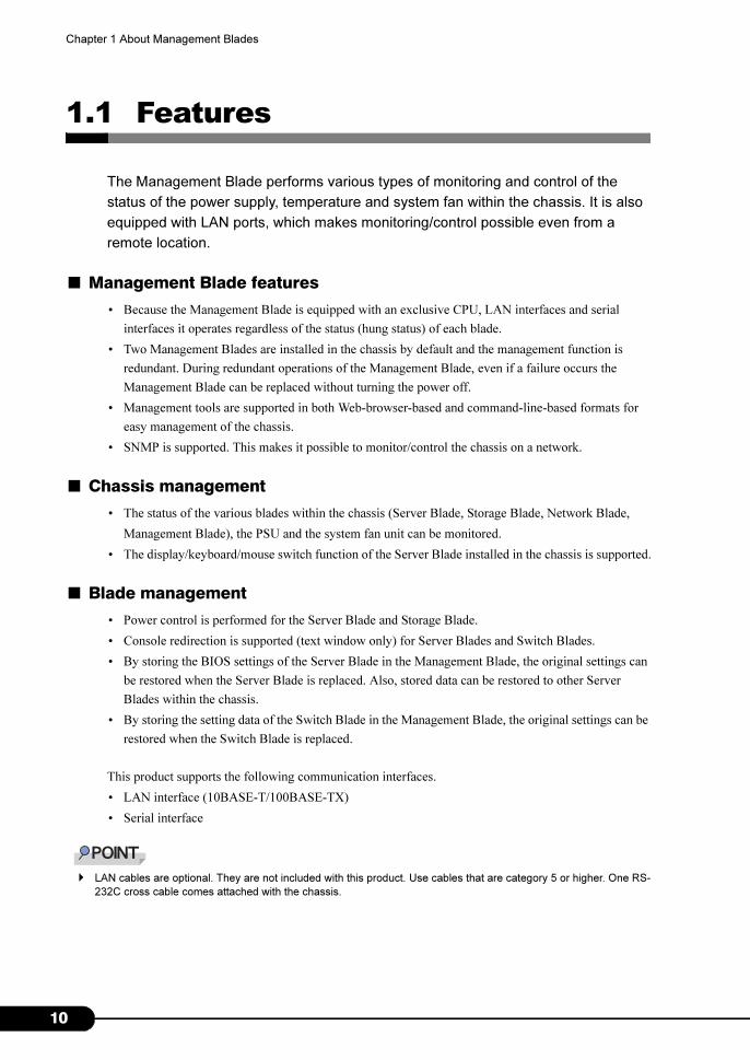
The Management Blade performs various types of monitoring and control of the
status of the power supply, temperature and system fan within the chassis. It is also
equipped with LAN ports, which makes monitoring/control possible even from a
remote location.
■ Management Blade features
• Because the Management Blade is equipped with an exclusive CPU, LAN interfaces and serial
interfaces it operates regardless of the status (hung status) of each blade.
• Two Management Blades are installed in the chassis by default and the management function is
redundant. During redundant operations of the Management Blade, even if a failure occurs the
Management Blade can be replaced without turning the power off.
• Management tools are supported in both Web-browser-based and command-line-based formats for
easy management of the chassis.
• SNMP is supported. This makes it possible to monitor/control the chassis on a network.
■ Chassis management
• The status of the various blades within the chassis (Server Blade, Storage Blade, Network Blade,
Management Blade), the PSU and the system fan unit can be monitored.
• The display/keyboard/mouse switch function of the Server Blade installed in the chassis is supported.
■ Blade management
• Power control is performed for the Server Blade and Storage Blade.
• Console redirection is supported (text window only) for Server Blades and Switch Blades.
• By storing the BIOS settings of the Server Blade in the Management Blade, the original settings can
be restored when the Server Blade is replaced. Also, stored data can be restored to other Server
Blades within the chassis.
• By storing the setting data of the Switch Blade in the Management Blade, the original settings can be
restored when the Switch Blade is replaced.
This product supports the following communication interfaces.
• LAN interface (10BASE-T/100BASE-TX)
• Serial interface
� LAN cables are optional. They are not included with this product. Use cables that are category 5 or higher. One RS-
232C cross cable comes attached with the chassis.
0
PRIMERGY BX600 Management Blade Hardware Guide
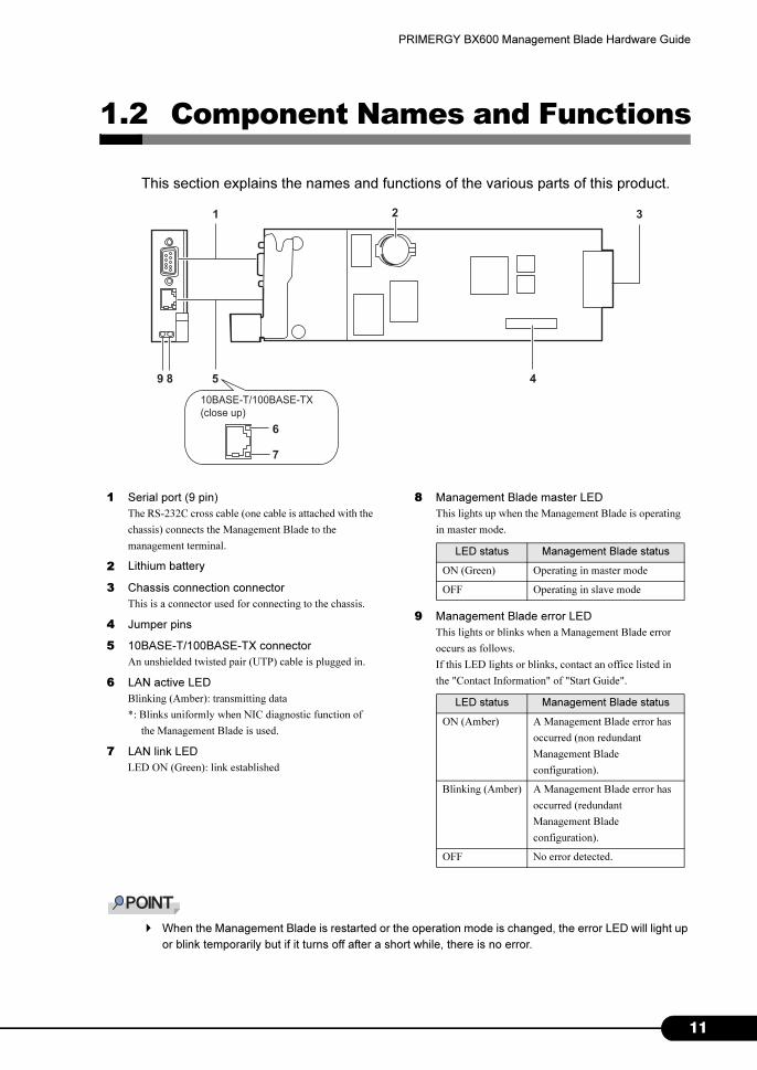
1.2 Component Names and Functions
This section explains the names and functions of the various parts of this product.
� When the Management Blade is restarted or the operation mode is changed, the error LED will light up
or blink temporarily but if it turns off after a short while, there is no error.
1 3
4
2
5
6
7
89
10BASE-T/100BASE-TX
(close up)
1 Serial port (9 pin)
The RS-232C cross cable (one cable is attached with the
chassis) connects the Management Blade to the
management terminal.
2 Lithium battery
3 Chassis connection connector
This is a connector used for connecting to the chassis.
4 Jumper pins
5 10BASE-T/100BASE-TX connector
An unshielded twisted pair (UTP) cable is plugged in.
6 LAN active LED
Blinking (Amber): transmitting data
*: Blinks uniformly when NIC diagnostic function of
the Management Blade is used.
7 LAN link LED
LED ON (Green): link established
8 Management Blade master LED
This lights up when the Management Blade is operating
in master mode.
9 Management Blade error LED
This lights or blinks when a Management Blade error
occurs as follows.
If this LED lights or blinks, contact an office listed in
the "Contact Information" of "Start Guide".
LED status Management Blade status
ON (Green) Operating in master mode
OFF Operating in slave mode
LED status Management Blade status
ON (Amber) A Management Blade error has
occurred (non redundant
Management Blade
configuration).
Blinking (Amber) A Management Blade error has
occurred (redundant
Management Blade
configuration).
OFF No error detected.
11

1
Chapter 1 About Management Blades
2
Chapter 2
Installing and Removing Management Blades
This chapter explains how to install/remove
Management Blades to the chassis and default
settings.
2.1 Before Starting . . . . . . . . . . . . . . . . . . . . . . . . . . . . . . . . 14
2.2 Installing and Removing . . . . . . . . . . . . . . . . . . . . . . . . . 15
2.3 Default Settings . . . . . . . . . . . . . . . . . . . . . . . . . . . . . . . . 16
13
1
Chapter 2 Installing and Removing Management Blades
2.1 Before Starting
Perform the following preparations before installing/ removing a Management Blade
to the chassis.
■ Preparations
Before starting prepare the following.
• Management Blade
• The server and manual for each optional component
• Management terminal (PC etc.)
� It is necessary to have a normal environment in which Web browser and terminal software operates in
the management terminal. Also, LAN ports or serial ports are necessary as communication interfaces.
4
PRIMERGY BX600 Management Blade Hardware Guide
2.2 Installing and Removing
For details about installing/removing Management Blades, refer to "BX600 S3 Blade
Server System Unit Hardware Guide".
� For the Management Blades to monitor the chassis constantly, blade system management starts
approx. 1 minute after the power cable of the chassis has been plugged in.
� Always use the same Management Blade firmware version in both Management Blades (excluding
firmware being updated).
15
1
Chapter 2 Installing and Removing Management Blades
2.3 Default Settings
Before using the Management Blade, some default settings must be performed.
2.3.1 Management Software
Management Blade supports management tools such as Web UI (web user interface) and CLI (command
line interface). Using these management tools, the chassis of the blade server and various blades can be
easily managed from the management terminal.
• The Web UI operates/manages using the Web browser via the LAN.
• CLI operates/manages using a command line base on the console menu that uses serial ports or Telnet
protocol via LAN.
2.3.2 Communication Interface Settings
Perform the necessary settings from among the following depending on the management tools and
method of communication to be used.
• When using Web UI or CLI via Telnet
�"■ LAN Interface Settings" (p.16)
• When using CLI via a serial interface
�"■ Serial Interface Settings" (p.18)
� Access the various management tools using the user name "root", password "root" as set in the default
user settings during default settings. Password is case sensitive.
■ LAN Interface Settings
The procedures for settings LAN interface are as follows.
� The LAN interfaces of Management Blade can be set to 10Mbps full duplex/ 10Mbps half duplex/
100Mbps full duplex/ 100Mbps half duplex/ auto-negotiation. Set the same setting to the connecting
hub. If they are connected in different settings, the level of communication efficiency may severely
decrease or communication may fail.
6
PRIMERGY BX600 Management Blade Hardware Guide
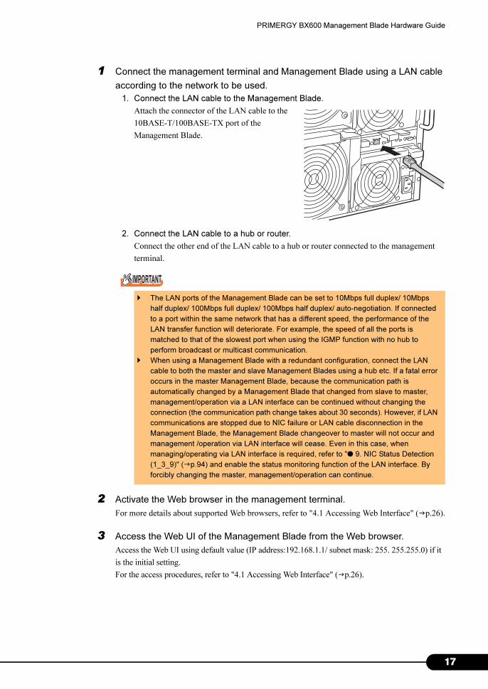
1 Connect the management terminal and Management Blade using a LAN cable
according to the network to be used.
1. Connect the LAN cable to the Management Blade.
Attach the connector of the LAN cable to the
10BASE-T/100BASE-TX port of the
Management Blade.
2. Connect the LAN cable to a hub or router.
Connect the other end of the LAN cable to a hub or router connected to the management
terminal.
2 Activate the Web browser in the management terminal.
For more details about supported Web browsers, refer to "4.1 Accessing Web Interface" (�p.26).
3 Access the Web UI of the Management Blade from the Web browser.
Access the Web UI using default value (IP address:192.168.1.1/ subnet mask: 255. 255.255.0) if it
is the initial setting.
For the access procedures, refer to "4.1 Accessing Web Interface" (�p.26).
� The LAN ports of the Management Blade can be set to 10Mbps full duplex/ 10Mbps
half duplex/ 100Mbps full duplex/ 100Mbps half duplex/ auto-negotiation. If connected
to a port within the same network that has a different speed, the performance of the
LAN transfer function will deteriorate. For example, the speed of all the ports is
matched to that of the slowest port when using the IGMP function with no hub to
perform broadcast or multicast communication.
� When using a Management Blade with a redundant configuration, connect the LAN
cable to both the master and slave Management Blades using a hub etc. If a fatal error
occurs in the master Management Blade, because the communication path is
automatically changed by a Management Blade that changed from slave to master,
management/operation via a LAN interface can be continued without changing the
connection (the communication path change takes about 30 seconds). However, if LAN
communications are stopped due to NIC failure or LAN cable disconnection in the
Management Blade, the Management Blade changeover to master will not occur and
management /operation via LAN interface will cease. Even in this case, when
managing/operating via LAN interface is required, refer to "● 9. NIC Status Detection
(1_3_9)" (�p.94) and enable the status monitoring function of the LAN interface. By
forcibly changing the master, management/operation can continue.
17
1
Chapter 2 Installing and Removing Management Blades
4 Perform LAN interface settings by clicking on [System Property] – [LAN
Interface] in the setting parameter menu of the displayed Management Blade
initial screen in this order.
For details about setting methods, refer to "● LAN Interface" (�p.29).
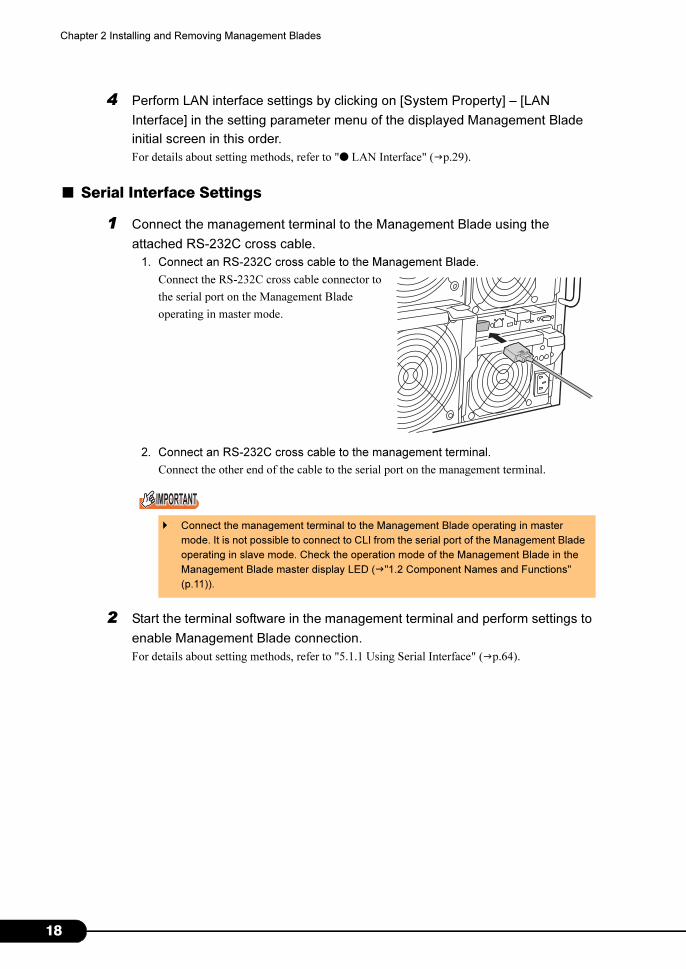
■ Serial Interface Settings
1 Connect the management terminal to the Management Blade using the
attached RS-232C cross cable.
1. Connect an RS-232C cross cable to the Management Blade.
Connect the RS-232C cross cable connector to
the serial port on the Management Blade
operating in master mode.
2. Connect an RS-232C cross cable to the management terminal.
Connect the other end of the cable to the serial port on the management terminal.
2 Start the terminal software in the management terminal and perform settings to
enable Management Blade connection.
For details about setting methods, refer to "5.1.1 Using Serial Interface" (�p.64).
� Connect the management terminal to the Management Blade operating in master
mode. It is not possible to connect to CLI from the serial port of the Management Blade
operating in slave mode. Check the operation mode of the Management Blade in the
Management Blade master display LED (�"1.2 Component Names and Functions"
(p.11)).
8
PRIMERGY BX600 Management Blade Hardware Guide
2.3.3 Management User Settings
A user name "root" and password "root" that have administrator privileges are set by default to the
Management Blade.
To ensure the security, make sure to change the password.
■ Changing the password from Web UI
1 Access the Web UI from the management terminal.
2 Click [System Property] – [User Accounts].
The "User Accounts" page appears.
3 Click [root].
The "Account" page of the User name: root appears.
4 Enter the following parameter and click [Apply].
• Password: Enter a new password.
• Confirm Password: Enter the new password again.
■ Changing the password from CLI
1 Log in to the CLI from the management terminal.
2 Move in the order of "(1) Management Agent" – "(6) Username And Password".
Select (1), "root".
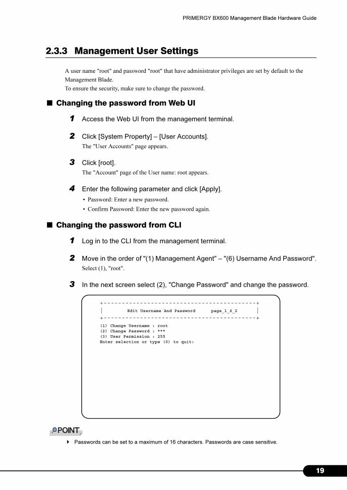
3 In the next screen select (2), "Change Password" and change the password.
� Passwords can be set to a maximum of 16 characters. Passwords are case sensitive.
+------------------------------------------+| |+------------------------------------------+
Edit Username And Password page_1_6_2
(1) Change Username : root(2) Change Password : ***(3) User Permission : 255Enter selection or type (0) to quit:
19
2
Chapter 2 Installing and Removing Management Blades
2.3.4 Blade Server Time Management
It is necessary to perform/check Management Blade time and time zone settings during initial setting.
Perform checks/settings in Web UI (�"● System Information" (p.45)) or CLI (�"■ Management Agent
Information (1_1)" (p.71)).
Note the following when checking/setting.
■ Server Blade and Management Blade time synchronization
The time of the Server Blade installed in the chassis can be synchronized with the time of the
Management Blade by enabling "Sync RTC with Mgmt. Blade" using the BIOS setup (Default value is
[Enabled]).
Using this function, the time of multiple Server Blades and Management Blades installed in the chassis
can be synchronized.
→ "BX620 S4 Server Blade User's Guide Chapter 8 Hardware Configuration/Utilities"
■ Management Blade time synchronization via the network
Management Blade supports NTP as a time synchronization system via the network. Set in Web UI (�"•
NTP" (p.40)) or CLI (�"● 17. Agent NTP (1_1_17)" (p.78)). When using this function, complete
settings or checking before starting blade server operations or when suspended.
� Disable "Sync RTC with Mgmt. Blade" if you do not wish to perform time synchronization for Server
Blade and Management Blade for reasons such as a precise system time being demanded of the
Server Blade. In this case incorporate a time synchronization system (NTP etc.) via the network in
the Server Blade system design.
� Do not change NTP settings during blade server operation. Doing so may cause a system failure by
the time synchronization of the Management and Server Blades in the OS etc.
0
PRIMERGY BX600 Management Blade Hardware Guide
2.3.5 Various Setting Values
In order to operate the Management Blade, perform settings in order to they conform with the
installation environment on the management tools.
2.3.6 Points to Note During Management Blade Operations
The following are points to notice for Management Blade operations.
■ Management Blade redundancy function
Two Management Blades are installed in this server by default and the management function is
redundant.
In a redundant configuration, one Management Blade operates in master mode and the other in slave
mode. During normal operations, the Management Blade operating in master mode performs system
management and operations. The Management Blade operating in slave mode is continuously
monitoring the master.
If an error occurs in the master the slave will detect this and switch with the master enabling
management and operations to continue without stopping.
� As long as there is no error in the Management Blade, immediately after the power cable has been
connected the Management Blade installed in slot 1 operates as the master.
� Store the various setting values set in the Management Blade in the hard copy of screens, take
note, or record in the Configuration Sheets. This is necessary when maintaining or restoring
settings.
� Always use the same Management Blade firmware version in both Management Blades (excluding
firmware being updated).
21

2
Chapter 2 Installing and Removing Management Blades
2
Chapter 3
Software
This chapter explains the software that can be
used in collaboration with Management Blades.
3.1 Software . . . . . . . . . . . . . . . . . . . . . . . . . . . . . . . . . . . . . 24
23
2
Chapter 3 Software
3.1 Software
The following software is used with Management Blades.
• ServerView V3.50 or later
Blade server system status monitoring and remote operations can be performed from the ServerView
management console.
• RemoteControlService V3.06 or later
CLI operations can be performed via Telnet.
ServerView management console and RemoteControlService are stored in the PRIMERGY Startup
Disc.
For details about how to install ServerView and RemoteControlService, refer to the "Server Blade
User's Guide" and the "ServerView User's Guide".
� In order to use ServerView, the following settings must be performed for Management Blade.
• Connect the management terminal to which ServerView management console has been installed
with Management Blade and Server Blade using the LAN.
• Set IP address and subnet mask in the LAN interface settings.
• Set SNMP to "Enable" and set the SNMP community name to be the same as ServerView in SNMP
settings.
• Set the IP address of the management terminal installed in the ServerView management console in
"SNMP Trap Destination".
• Set Management Agent System Name (recommended).
- "Agent Information" of Web UI (�"● System Information" (p.45))
- "9. Agent System Info" of CLI (�"■ Management Agent Information (1_1)" (p.71))
4
Chapter 4
Web UI
This chapter explains the Web UI which enables
the management and operation of the blade
server system in the Management Blade.
4.1 Accessing Web Interface . . . . . . . . . . . . . . . . . . . . . . . . . 26
4.2 Web UI Menu . . . . . . . . . . . . . . . . . . . . . . . . . . . . . . . . . 27
25
2
Chapter 4 Web UI
4.1 Accessing Web Interface
Management Blade supports Web interface (Web UI) and can be accessed from the
following Web browsers.
• Internet Explorer (Version 5.0, 5.5, 6.0 or later)
• Netscape (Version 4.75, 4.78, 6.x or later (*))
*: When using the SSL function, Version 7.0 or later is required.
To access Management Blade from Web UI, execute the Web browser and enter the following address in
the address bar. Enter the IP address of the Management Blade in <IP address>.
• http://<IP address >:< Port number (default:80)> (when HTTP SSL is "disable")
• https://<IP address >:< Port number (default:443)> (when HTTP SSL is "enable")
A dialog box will appear. Enter the user name and password to login.
� HTTP SSL is set to "Disable" by default.
� The Web interface can be accessed from the ServerView management console. For details about
access methods, refer to "Chapter 3 How to use ServerView" in the "ServerView User's Guide".
6
PRIMERGY BX600 Management Blade Hardware Guide
4.2 Web UI Menu
4.2.1 Start Screen
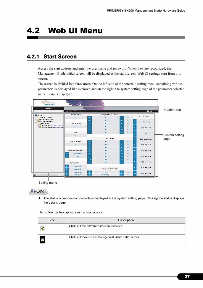
Access the start address and enter the user name and password. When they are recognized, the
Management Blade initial screen will be displayed as the start screen. Web UI settings start from this
screen.
The screen is divided into three areas. On the left side of the screen, a setting menu containing various
parameters is displayed like explorer, and on the right, the system setting page of the parameter selected
in the menu is displayed.
� The status of various components is displayed in the system setting page. Clicking the status displays
the details page.
The following link appears in the header area.
Icon Description
Click and the relevant frames are reloaded.
Click and move to the Management Blade initial screen.
Header area
System setting
page
Setting menu
27
2
Chapter 4 Web UI
4.2.2 Settings Menu
The system configuration, properties and blades installed in the blade server system are displayed in the
settings menu on the left side of the screen. This page is divided into 4 groups, "System Property",
"Management Blade", "Switch Blade" and "Server Blade".
■ System Property group
This group is used for system configuration.
�"4.2.4 System Property Group" (p.32)
● System Event Log
Displays logs and sets the alarm handler.
�"● System Event Log" (p.32)
• Event Log
Displays event logs related to Management Blades and Server Blades.
• Alarm Handler
Sets alarm handler.
● Environment/Maintenance
This sets operations and monitors the status for the devices such as the chassis, fan, and PSU.
Also performs reboot settings for Management Blades.
�"● Environment/Maintenance" (p.34)
• Firmware Update
Not normally used.
• Power Supply
Displays the status and running time of PSU and also performs the settings for ON/OFF of the main
power supply of the chassis and the concurrent ON/OFF settings of the power supply of the Server
Blades.
• UPS
Not used.
• Chassis
Displays the door status of the chassis, displays and sets temperature of the chassis, and indicates if
the maintenance LED is lit.
• Fans
Displays and sets the status and running time of the system fan unit and sets the fan test.
• Reset management Blade
Reboots the Management Blade.
8
PRIMERGY BX600 Management Blade Hardware Guide
● LAN Interface
Performs settings for network configuration.
�"● LAN Interface" (p.39)
• Internet Protocol
Sets the IP address etc.
• Domain Name Server
Sets DNS.
• HTTP
Sets the port number etc. of the HTTP.
• Telnet
Sets the port number etc. of telnet.
• NTP
Sets NTP.
• SSL
Sets SSL.
• Duplex Mode
Sets transfer speed.
● SNMP Interface
Sets information regarding SNMP.
�"● SNMP Interface" (p.42)
• SNMP Communities
Sets the SNMP community name.
• SNMP Trap Destination
Sets the SNMP trap destination.
● Console Redirection
Performs settings related to console redirection.
�"● Console Redirection" (p.43)
• Keyboard/Mouse/Video Switch to Local
Performs Keyboard/Display/Mouse (KVM) switch settings.
• IP Filter for Telnet/IP Filter for HTTP/IP Filter for SNMP
Sets IP filtering.
● Fiber Channel
Displays the status of the FC Pass-Thru Blade.
�"● Fiber Channel" (p.44)
● System Information
Sets agent information, time, and the time zone.
�"● System Information" (p.45)
29
3
Chapter 4 Web UI
● User Accounts
Adds new users and changes the password.
�"● User Accounts" (p.46)
● Deployment Table
Displays and sets the Parameters of various Server Blades that can be used with Deployment software.
�"● Deployment Table" (p.47)
● PPP and Modem Setting
This function is not supported.
■ Management Blade group
Displays the information of installed Management Blades.
�"4.2.5 Management Blade Group" (p.48)
■ Lan Switch Blade group
Displays the information and sets the maintenance LED of installed Switch Blades.
�"4.2.6 Lan Switch Blade Group" (p.49)
■ PHY Module group
Displays the information and sets the maintenance LED of installed GbE Pass-Thru Blade.
�"4.2.7 PHY Module Group" (p.50)
■ FC Switch Blade group
Displays the information of installed Fibre Channel Switch Blade.
�"4.2.8 FC Switch Blade Group" (p.51)
■ Adv.KVM Blade group (when PG-KVB102 is installed)
Displays the information and manages the firmware of installed advanced KVM module (PG-KVB102).
Also starts the viewer used for remote access to KVM.
�"4.2.9 Adv. KVM Blade Group (when PG-KVB102 is installed)" (p.52)
■ DKVM Blade group (when PG-KVB103 is installed)
Displays the information and manages the firmware of installed advanced KVM module (PG-KVB103).
Also starts the viewer used to remotely access KVM, and starts the tools for using the remote floppy disk
drives and CD/DVD drives in the Server Blade.
�"4.2.10 DKVM Blade Group (when PG-KVB103 is installed)" (p.53)
■ Server Blade group
Displays the information of installed Server Blades and Storage Blades, and performs various settings.
�"4.2.11 Server Blade Group" (p.55)
0
PRIMERGY BX600 Management Blade Hardware Guide
4.2.3 System Settings Page
The system settings page displayed in the right of the screen shows the various settings and information
of the item selected in the settings menu.
In the system settings page all the page header and footer areas are configured using the same method.
The title of the current page appears in the header area.
The following information appears in the footer area.
• Controller time
Check the time and date of the Management Blade.
� The time and date displayed is the time and date when the Web page was accessed.
The following link appears in the both the header and footer areas.
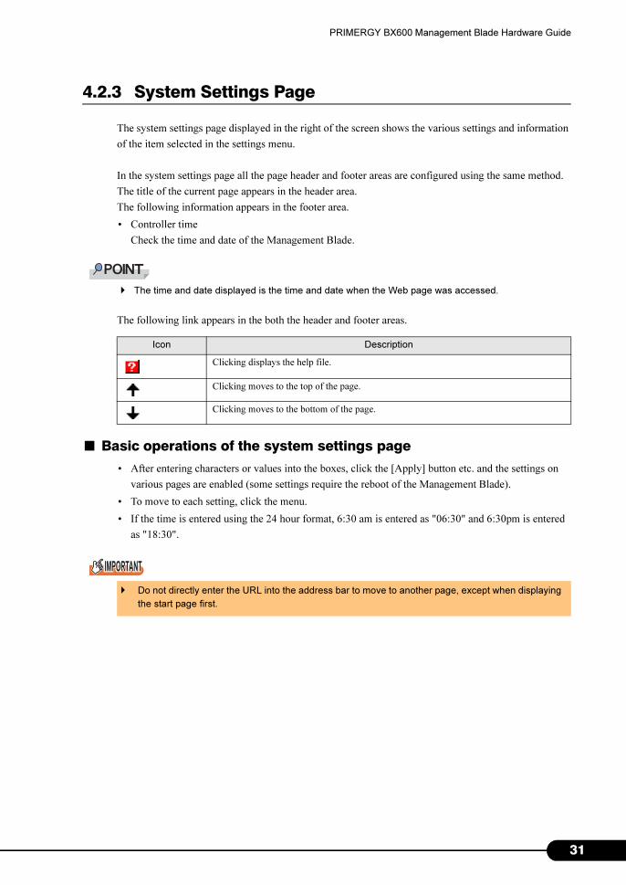
■ Basic operations of the system settings page
• After entering characters or values into the boxes, click the [Apply] button etc. and the settings on
various pages are enabled (some settings require the reboot of the Management Blade).
• To move to each setting, click the menu.
• If the time is entered using the 24 hour format, 6:30 am is entered as "06:30" and 6:30pm is entered
as "18:30".
Icon Description
Clicking displays the help file.
Clicking moves to the top of the page.
Clicking moves to the bottom of the page.
� Do not directly enter the URL into the address bar to move to another page, except when displaying
the start page first.
31
3
Chapter 4 Web UI
4.2.4 System Property Group
This group is used for system configuration.
● System Event Log
The Management Blade and Server Blade event logs are displayed and alarm handler settings are
performed on the System Event Log page. Management Blade logs include event logs related to the
chassis.
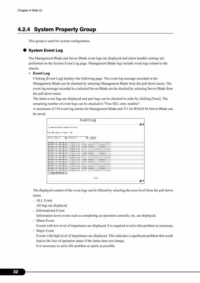
• Event Log
Clicking [Event Log] displays the following page. The event log message recorded in the
Management Blade can be checked by selecting Management Blade from the pull down menu. The
event log message recorded in a selected Server Blade can be checked by selecting Server Blade from
the pull down menu.
The latest event logs are displayed and past logs can be checked in order by clicking [Next]. The
remaining number of event logs can be checked in "Free SEL entry number".
A maximum of 510 event log entries for Management Blade and 511 for BX620 S4 Server Blade can
be saved.
The displayed content of the event logs can be filtered by selecting the error level from the pull down
menu.
- ALL Event
All logs are displayed.
- Informational Event
Information level events such as completing an operation correctly, etc. are displayed.
- Minor Event
Events with low level of importance are displayed. It is required to solve this problem as necessary.
- Major Event
Events with high level of importance are displayed. This indicates a significant problem that could
lead to the loss of operation status if the status does not change.
It is necessary to solve this problem as quick as possible.
2
PRIMERGY BX600 Management Blade Hardware Guide
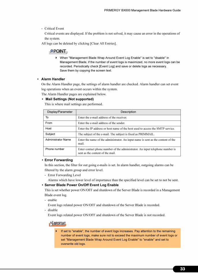
- Critical Event
Critical events are displayed. If the problem is not solved, it may cause an error in the operations of
the system.
All logs can be deleted by clicking [Clear All Entries].
� When "Management Blade Wrap Around Event Log Enable" is set to "disable" in
Management Blade, if the number of event logs is maximized, no more event logs can be
recorded. Periodically check [Event Log] and save or delete logs as necessary.
Save them by copying the screen text.
• Alarm Handler
On the Alarm Handler page, the settings of alarm handler are checked. Alarm handler can set event
log operations when an event occurs within the system.
The Alarm Handler pages are explained below.
• Mail Settings (Not supported)
This is where mail settings are performed.
• Error Forwarding
In this section, the filter for out going e-mails is set. In alarm handler, outgoing alarms can be
filtered by the alarm group and error level.
- Error Forwarding Level
Alarms which have lower level of importance than the specified level can be set to not be sent.
• Server Blade Power On/Off Event Log Enable
This is set whether power ON/OFF and shutdown of the Server Blade is recorded in a Management
Blade event log.
- enable
Event logs related power ON/OFF and shutdown of the Server Blade is recorded.
- disable
Event logs related power ON/OFF and shutdown of the Server Blade is not recorded.
Display/Parameter Description
To Enter the e-mail address of the receiver.
From Enter the e-mail address of the sender.
Host Enter the IP address or host name of the host used to access the SMTP service.
Subject The subject of the e-mail. The subject is fixed as PRIMMAIL.
Administrator Name Enter the name of the administrator. An input name is sent as the content of the
mail.
Phone number Enter contact phone number of the administrator. An input telephone number is
sent as the content of the mail.
� If set to "enable", the number of event logs increases. Pay attention to the remaining
number of event logs, make sure not to exceed the maximum number of event logs or
set "Management Blade Wrap Around Event Log Enable" to "enable" and set to
overwrite old logs.
33
3
Chapter 4 Web UI
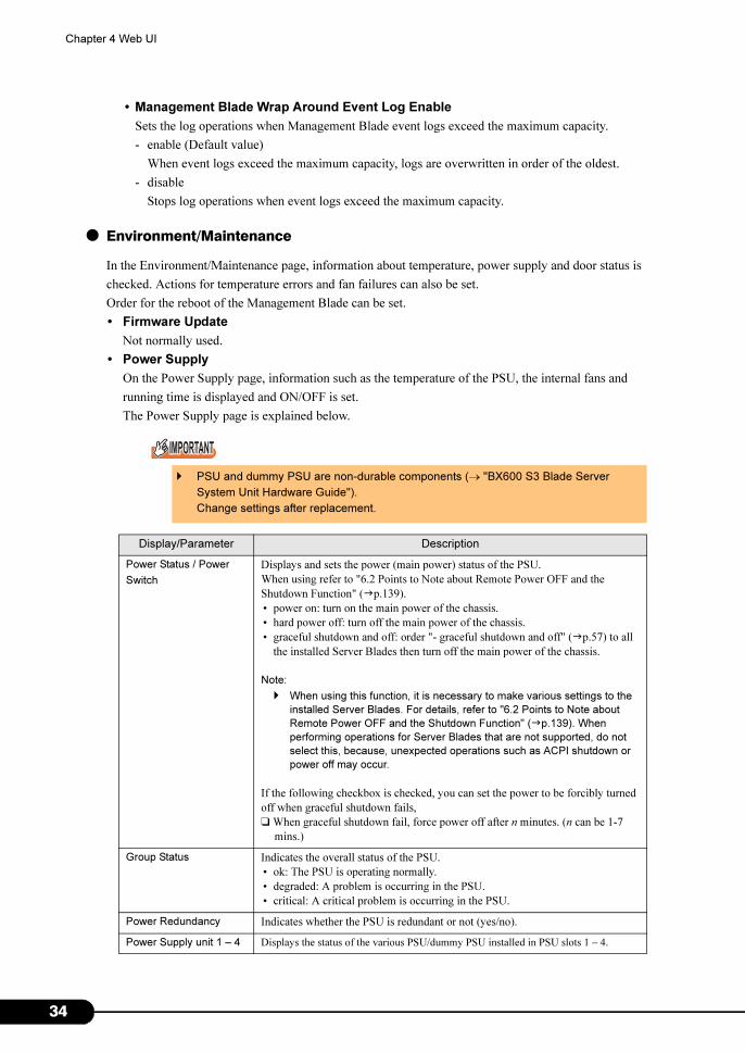
• Management Blade Wrap Around Event Log Enable
Sets the log operations when Management Blade event logs exceed the maximum capacity.
- enable (Default value)
When event logs exceed the maximum capacity, logs are overwritten in order of the oldest.
- disable
Stops log operations when event logs exceed the maximum capacity.
● Environment/Maintenance
In the Environment/Maintenance page, information about temperature, power supply and door status is
checked. Actions for temperature errors and fan failures can also be set.
Order for the reboot of the Management Blade can be set.
• Firmware Update
Not normally used.
• Power Supply
On the Power Supply page, information such as the temperature of the PSU, the internal fans and
running time is displayed and ON/OFF is set.
The Power Supply page is explained below.
� PSU and dummy PSU are non-durable components (→ "BX600 S3 Blade Server
System Unit Hardware Guide").
Change settings after replacement.
Display/Parameter Description
Power Status / Power
Switch
Displays and sets the power (main power) status of the PSU.
When using refer to "6.2 Points to Note about Remote Power OFF and the
Shutdown Function" (�p.139).
• power on: turn on the main power of the chassis.
• hard power off: turn off the main power of the chassis.
• graceful shutdown and off: order "- graceful shutdown and off" (�p.57) to all
the installed Server Blades then turn off the main power of the chassis.
Note:
� When using this function, it is necessary to make various settings to the
installed Server Blades. For details, refer to "6.2 Points to Note about
Remote Power OFF and the Shutdown Function" (�p.139). When
performing operations for Server Blades that are not supported, do not
select this, because, unexpected operations such as ACPI shutdown or
power off may occur.
If the following checkbox is checked, you can set the power to be forcibly turned
off when graceful shutdown fails,
❑ When graceful shutdown fail, force power off after n minutes. (n can be 1-7
mins.)
Group Status Indicates the overall status of the PSU.
• ok: The PSU is operating normally.
• degraded: A problem is occurring in the PSU.
• critical: A critical problem is occurring in the PSU.
Power Redundancy Indicates whether the PSU is redundant or not (yes/no).
Power Supply unit 1 – 4 Displays the status of the various PSU/dummy PSU installed in PSU slots 1 – 4.
4
PRIMERGY BX600 Management Blade Hardware Guide
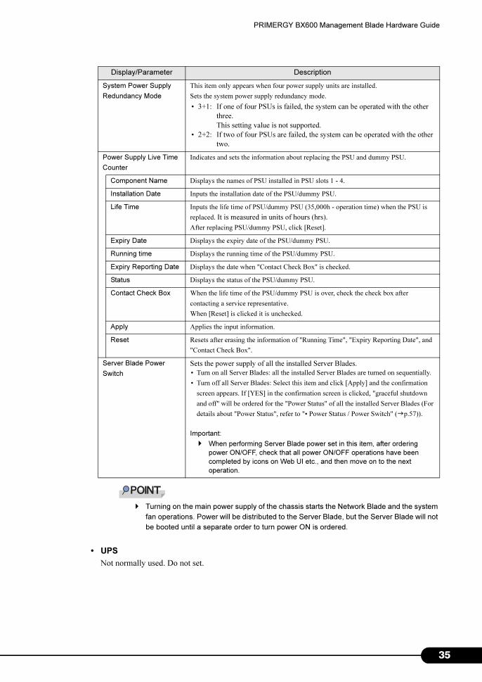
� Turning on the main power supply of the chassis starts the Network Blade and the system
fan operations. Power will be distributed to the Server Blade, but the Server Blade will not
be booted until a separate order to turn power ON is ordered.
• UPS
Not normally used. Do not set.
System Power Supply
Redundancy Mode
This item only appears when four power supply units are installed.
Sets the system power supply redundancy mode.
• 3+1: If one of four PSUs is failed, the system can be operated with the other
three.
This setting value is not supported.
• 2+2: If two of four PSUs are failed, the system can be operated with the other
two.
Power Supply Live Time
Counter
Indicates and sets the information about replacing the PSU and dummy PSU.
Component Name Displays the names of PSU installed in PSU slots 1 - 4.
Installation Date Inputs the installation date of the PSU/dummy PSU.
Life Time Inputs the life time of PSU/dummy PSU (35,000h - operation time) when the PSU is
replaced. It is measured in units of hours (hrs).
After replacing PSU/dummy PSU, click [Reset].
Expiry Date Displays the expiry date of the PSU/dummy PSU.
Running time Displays the running time of the PSU/dummy PSU.
Expiry Reporting Date Displays the date when "Contact Check Box" is checked.
Status Displays the status of the PSU/dummy PSU.
Contact Check Box When the life time of the PSU/dummy PSU is over, check the check box after
contacting a service representative.
When [Reset] is clicked it is unchecked.
Apply Applies the input information.
Reset Resets after erasing the information of "Running Time", "Expiry Reporting Date", and
"Contact Check Box".
Server Blade Power
Switch
Sets the power supply of all the installed Server Blades.
• Turn on all Server Blades: all the installed Server Blades are turned on sequentially.
• Turn off all Server Blades: Select this item and click [Apply] and the confirmation
screen appears. If [YES] in the confirmation screen is clicked, "graceful shutdown
and off" will be ordered for the "Power Status" of all the installed Server Blades (For
details about "Power Status", refer to "• Power Status / Power Switch" (�p.57)).
Important:
� When performing Server Blade power set in this item, after ordering
power ON/OFF, check that all power ON/OFF operations have been
completed by icons on Web UI etc., and then move on to the next
operation.
Display/Parameter Description
35
3
Chapter 4 Web UI
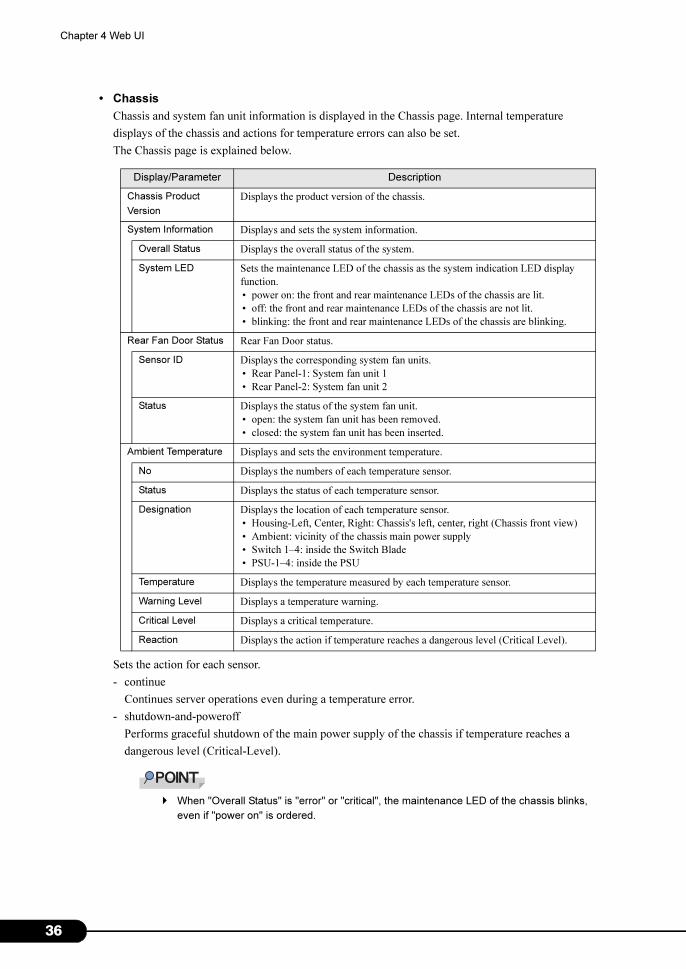
• Chassis
Chassis and system fan unit information is displayed in the Chassis page. Internal temperature
displays of the chassis and actions for temperature errors can also be set.
The Chassis page is explained below.
Sets the action for each sensor.
- continue
Continues server operations even during a temperature error.
- shutdown-and-poweroff
Performs graceful shutdown of the main power supply of the chassis if temperature reaches a
dangerous level (Critical-Level).
� When "Overall Status" is "error" or "critical", the maintenance LED of the chassis blinks,
even if "power on" is ordered.
Display/Parameter Description
Chassis Product
Version
Displays the product version of the chassis.
System Information Displays and sets the system information.
Overall Status Displays the overall status of the system.
System LED Sets the maintenance LED of the chassis as the system indication LED display
function.
• power on: the front and rear maintenance LEDs of the chassis are lit.
• off: the front and rear maintenance LEDs of the chassis are not lit.
• blinking: the front and rear maintenance LEDs of the chassis are blinking.
Rear Fan Door Status Rear Fan Door status.
Sensor ID Displays the corresponding system fan units.
• Rear Panel-1: System fan unit 1
• Rear Panel-2: System fan unit 2
Status Displays the status of the system fan unit.
• open: the system fan unit has been removed.
• closed: the system fan unit has been inserted.
Ambient Temperature Displays and sets the environment temperature.
No Displays the numbers of each temperature sensor.
Status Displays the status of each temperature sensor.
Designation Displays the location of each temperature sensor.
• Housing-Left, Center, Right: Chassis's left, center, right (Chassis front view)
• Ambient: vicinity of the chassis main power supply
• Switch 1–4: inside the Switch Blade
• PSU-1–4: inside the PSU
Temperature Displays the temperature measured by each temperature sensor.
Warning Level Displays a temperature warning.
Critical Level Displays a critical temperature.
Reaction Displays the action if temperature reaches a dangerous level (Critical Level).
6
PRIMERGY BX600 Management Blade Hardware Guide
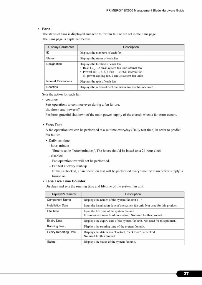
• Fans
The status of fans is displayed and actions for fan failure are set in the Fans page.
The Fans page is explained below.
Sets the action for each fan.
- continue
Sets operations to continue even during a fan failure.
- shutdown-and-poweroff
Performs graceful shutdown of the main power supply of the chassis when a fan error occurs.
• Fans Test
A fan operation test can be performed at a set time everyday (Daily test time) in order to predict
fan failure.
• Daily test time
- hour: minute
Time is set in "hours:minutes". The hours should be based on a 24-hour clock.
- disabled
Fan operation test will not be performed.
❑ Fan test at every start-up
If this is checked, a fan operation test will be performed every time the main power supply is
turned on.
• Fans Live Time Counter
Displays and sets the running time and lifetime of the system fan unit.
Display/Parameter Description
ID Displays the numbers of each fan.
Status Displays the status of each fan.
Designation Displays the location of each fan.
• Rear 1,2_1–2 fans: system fan unit internal fan
• PowerUnit 1, 2, 3, 4-Fan-1–3: PSU internal fan
(1: power cooling fan, 2 and 3: system fan unit)
Normal Revolutions Displays the rpm of each fan.
Reaction Displays the action of each fan when an error has occurred.
Display/Parameter Description
Component Name Displays the names of the system fan unit 1 - 4.
Installation Date Input the installation date of the system fan unit. Not used for this product.
Life Time Input the life time of the system fan unit.
It is measured in units of hours (hrs). Not used for this product.
Expiry Date Displays the expiry date of the system fan unit. Not used for this product.
Running time Displays the running time of the system fan unit.
Expiry Reporting Date Displays the date when "Contact Check Box" is checked.
Not used for this product.
Status Displays the status of the system fan unit.
37
3
Chapter 4 Web UI
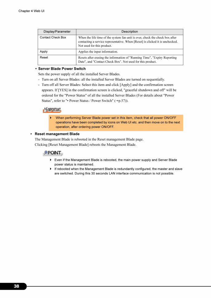
• Server Blade Power Switch
Sets the power supply of all the installed Server Blades.
- Turn on all Server Blades: all the installed Server Blades are turned on sequentially.
- Turn off all Server Blades: Select this item and click [Apply] and the confirmation screen
appears. If [YES] in the confirmation screen is clicked, "graceful shutdown and off" will be
ordered for the "Power Status" of all the installed Server Blades (For details about "Power
Status", refer to "• Power Status / Power Switch" (�p.57)).
• Reset management Blade
The Management Blade is rebooted in the Reset management Blade page.
Clicking [Reset Management Blade] reboots the Management Blade.
� Even if the Management Blade is rebooted, the main power supply and Server Blade
power status is maintained.
� If rebooted when the Management Blade is redundantly configured, the master and slave
are switched. During this 30 seconds LAN interface communication is not possible.
Contact Check Box When the life time of the system fan unit is over, check the check box after
contacting a service representative. When [Reset] is clicked it is unchecked.
Not used for this product.
Apply Applies the input information.
Reset Resets after erasing the information of "Running Time", "Expiry Reporting
Date", and "Contact Check Box". Not used for this product.
� When performing Server Blade power set in this item, check that all power ON/OFF
operations have been completed by icons on Web UI etc. and then move on to the next
operation, after ordering power ON/OFF.
Display/Parameter Description
8
PRIMERGY BX600 Management Blade Hardware Guide
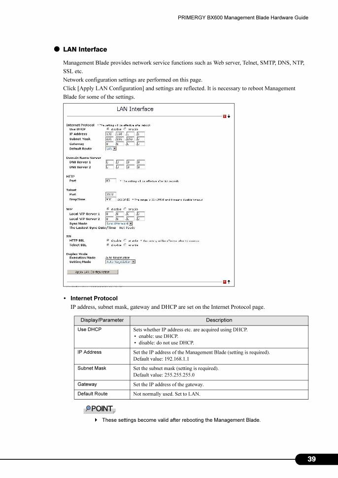
● LAN Interface
Management Blade provides network service functions such as Web server, Telnet, SMTP, DNS, NTP,
SSL etc.
Network configuration settings are performed on this page.
Click [Apply LAN Configuration] and settings are reflected. It is necessary to reboot Management
Blade for some of the settings.
• Internet Protocol
IP address, subnet mask, gateway and DHCP are set on the Internet Protocol page.
� These settings become valid after rebooting the Management Blade.
Display/Parameter Description
Use DHCP Sets whether IP address etc. are acquired using DHCP.
• enable: use DHCP.
• disable: do not use DHCP.
IP Address Set the IP address of the Management Blade (setting is required).
Default value: 192.168.1.1
Subnet Mask Set the subnet mask (setting is required).
Default value: 255.255.255.0
Gateway Set the IP address of the gateway.
Default Route Not normally used. Set to LAN.
39
4
Chapter 4 Web UI
• Domain Name Server
Domain Name Server (DNS) is set on the Domain Name Server page.
• HTTP
Port number is set on the HTTP page.
� Changes to port settings will make valid 10 seconds after the changes.
• Telnet
Port number and Drop Time settings are set on the Telnet page.
� The change to the Telnet port number becomes valid after rebooting the Management
Blade.
• NTP
The enabling/disabling of settings and NTP server settings are performed on the NTP page.
Display/Parameter Description
DNS Server 1 Sets the IP address of the primary DNS server.
DNS Server 2 Sets the IP address of the secondary DNS server.
Display/Parameter Description
Port Sets the port number of the HTTP interface.
Default value:80
Display/Parameter Description
Port Sets the port number of telnet.
Default value:3172
Drop Time Sets the amount of time (secs) until a hibernating Telnet connection automatically
disconnects.
This can be set within the range of 30–65535 seconds. If set to 0 the automatic
disconnection function is disabled.
Also, the set value will be the same as the "Management Agent Timeout (Sec)" on
the CLI.
Display/Parameter Description
NTP Sets whether to perform time synchronization in the Management Blade using
Network Time Protocol (NTP). If NTP is enabled, the time of the Management
Blade is synchronized with the NTP server every 15 minutes.
• enable: use NTP.
• disable: do not use NTP.
Local NTP Server 1 Sets the IP address of the primary NTP server.
Local NTP Server 2 Sets the IP address of the secondary NTP server.
0
PRIMERGY BX600 Management Blade Hardware Guide
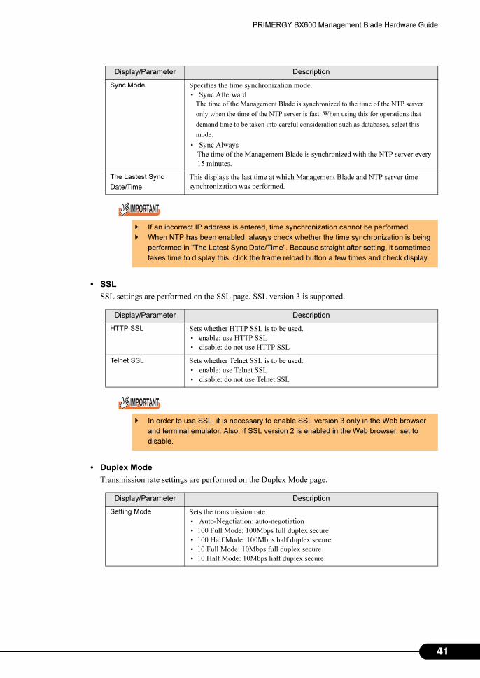
• SSL
SSL settings are performed on the SSL page. SSL version 3 is supported.
• Duplex Mode
Transmission rate settings are performed on the Duplex Mode page.
Sync Mode Specifies the time synchronization mode.
• Sync Afterward
The time of the Management Blade is synchronized to the time of the NTP server
only when the time of the NTP server is fast. When using this for operations that
demand time to be taken into careful consideration such as databases, select this
mode.
• Sync Always
The time of the Management Blade is synchronized with the NTP server every
15 minutes.
The Lastest Sync
Date/Time
This displays the last time at which Management Blade and NTP server time
synchronization was performed.
� If an incorrect IP address is entered, time synchronization cannot be performed.
� When NTP has been enabled, always check whether the time synchronization is being
performed in "The Latest Sync Date/Time". Because straight after setting, it sometimes
takes time to display this, click the frame reload button a few times and check display.
Display/Parameter Description
HTTP SSL Sets whether HTTP SSL is to be used.
• enable: use HTTP SSL
• disable: do not use HTTP SSL
Telnet SSL Sets whether Telnet SSL is to be used.
• enable: use Telnet SSL
• disable: do not use Telnet SSL
� In order to use SSL, it is necessary to enable SSL version 3 only in the Web browser
and terminal emulator. Also, if SSL version 2 is enabled in the Web browser, set to
disable.
Display/Parameter Description
Setting Mode Sets the transmission rate.
• Auto-Negotiation: auto-negotiation
• 100 Full Mode: 100Mbps full duplex secure
• 100 Half Mode: 100Mbps half duplex secure
• 10 Full Mode: 10Mbps full duplex secure
• 10 Half Mode: 10Mbps half duplex secure
Display/Parameter Description
41
4
Chapter 4 Web UI
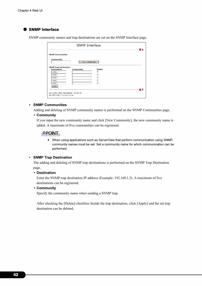
● SNMP Interface
SNMP community names and trap destinations are set on the SNMP Interface page.
• SNMP Communities
Adding and deleting of SNMP community names is performed on the SNMP Communities page.
• Community
If you input the new community name and click [New Community], the new community name is
added. A maximum of five communities can be registered.
� When using applications such as ServerView that perform communication using SNMP,
community names must be set. Set a community name for which communication can be
performed.
• SNMP Trap Destination
The adding and deleting of SNMP trap destinations is performed on the SNMP Trap Destination
page.
• Destination
Enter the SNMP trap destination IP address (Example: 192.168.1.2). A maximum of five
destinations can be registered.
• Community
Specify the community name when sending a SNMP trap.
After checking the [Delete] checkbox beside the trap destination, click [Apply] and the set trap
destination can be deleted.
2
PRIMERGY BX600 Management Blade Hardware Guide
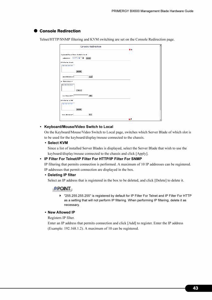
● Console Redirection
Telnet/HTTP/SNMP filtering and KVM switching are set on the Console Redirection page.
• Keyboard/Mouse/Video Switch to Local
On the Keyboard/Mouse/Video Switch to Local page, switches which Server Blade of which slot is
to be used for the keyboard/display/mouse connected to the chassis.
• Select KVM
Since a list of installed Server Blades is displayed, select the Server Blade that wish to use the
keyboard/display/mouse connected to the chassis and click [Apply].
• IP Filter For Telnet/IP Filter For HTTP/IP Filter For SNMP
IP filtering that permits connection is performed. A maximum of 10 IP addresses can be registered.
IP addresses that permit connection are displayed in the box.
• Deleting IP filter
Select an IP address that is registered in the box to be deleted, and click [Delete] to delete it.
� "255.255.255.255" is registered by default for IP Filter For Telnet and IP Filter For HTTP
as a setting that will not perform IP filtering. When performing IP filtering, delete it as
necessary.
• New Allowed IP
Registers IP filter.
Enter an IP address that permits connection and click [Add] to register. Enter the IP address
(Example: 192.168.1.2). A maximum of 10 can be registered.
43
4
Chapter 4 Web UI
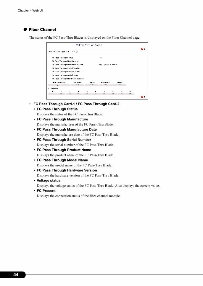
● Fiber Channel
The status of the FC Pass-Thru Blades is displayed on the Fiber Channel page.
• FC Pass Through Card-1 / FC Pass Through Card-2
• FC Pass Through Status
Displays the status of the FC Pass-Thru Blade.
• FC Pass Through Manufacture
Displays the manufacturer of the FC Pass-Thru Blade.
• FC Pass Through Manufacture Date
Displays the manufacture date of the FC Pass-Thru Blade.
• FC Pass Through Serial Number
Displays the serial number of the FC Pass-Thru Blade.
• FC Pass Through Product Name
Displays the product name of the FC Pass-Thru Blade.
• FC Pass Through Model Name
Displays the model name of the FC Pass-Thru Blade.
• FC Pass Through Hardware Version
Displays the hardware version of the FC Pass-Thru Blade.
• Voltage status
Displays the voltage status of the FC Pass-Thru Blade. Also displays the current value.
• FC Present
Displays the connection status of the fibre channel module.
4
PRIMERGY BX600 Management Blade Hardware Guide
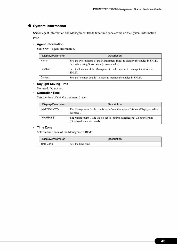
● System Information
SNMP agent information and Management Blade time/time zone are set on the System Information
page.
• Agent Information
Sets SNMP agent information.
• Daylight Saving Time
Not used. Do not set.
• Controller Time
Sets the time of the Management Blade.
• Time Zone
Sets the time zone of the Management Blade.
Display/Parameter Description
Name Sets the system name of the Management Blade to identify the device in SNMP.
Sets when using ServerView (recommended).
Location Sets the location of the Management Blade in order to manage the device in
SNMP.
Contact Sets the "contact details" in order to manage the device in SNMP.
Display/Parameter Description
(MM/DD/YYYY) The Management Blade date is set in "month/day/year" format (Displayed when
accessed).
(HH:MM:SS) The Management Blade time is set in "hour:minute:second" 24 hour format
(Displayed when accessed).
Display/Parameter Description
Time Zone Sets the time zone.
45
4
Chapter 4 Web UI
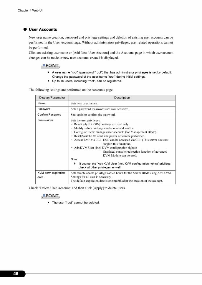
● User Accounts
New user name creation, password and privilege settings and deletion of existing user accounts can be
performed in the User Account page. Without administrators privileges, user related operations cannot
be performed.
Click an existing user name or [Add New User Account] and the Accounts page in which user account
changes can be made or new user accounts created is displayed.
� A user name "root" (password "root") that has administrator privileges is set by default.
Change the password of the user name "root" during initial settings.
� Up to 10 users, including "root", can be registered.
The following settings are performed on the Accounts page.
Check "Delete User Account" and then click [Apply] to delete users.
� The user "root" cannot be deleted.
Display/Parameter Description
Name Sets new user names.
Password Sets a password. Passwords are case sensitive.
Confirm Password Sets again to confirm the password.
Permissions Sets the user privileges.
• Read Only [LOGIN]: settings are read only
• Modify values: settings can be read and written.
• Configure users: manages user accounts (for Management Blade).
• Reset/Switch Off: reset and power off can be performed.
• Access EMP via CLI: EMP can be accessed via CLI. (This server does not
support this function).
• Adv.KVM User (incl. KVM configuration rights):
Graphical console redirection function of advanced
KVM Module can be used.
Note:
� If you set the “Adv.KVM User (incl. KVM configuration rights)” privilege,
check all other privileges as well.
KVM perm expiration
date
Sets remote access privilege earned hours for the Server Blade using Adv.KVM.
Settings for all user is necessary.
The default expiration date is one month after the creation of the account.
6
PRIMERGY BX600 Management Blade Hardware Guide
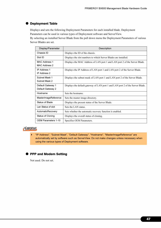
● Deployment Table
Displays and sets the following Deployment Parameters for each installed blade. Deployment
Parameters can be used in various types of Deployment software and ServerView.
By selecting an installed Server Blade from the pull down menu the Deployment Parameters of various
Server Blades are set.
● PPP and Modem Setting
Not used. Do not set.
Display/Parameter Description
Chassis ID Displays the ID of the chassis.
Slot ID Displays the slot numbers to which Server Blades are installed.
MAC Address 1
MAC Address 2
Displays the MAC Address of LAN port 1 and LAN port 2 of the Server Blade.
IP Address 1
IP Address 2
Displays the IP Address of LAN port 1 and LAN port 2 of the Server Blade.
Subnet Mask 1
Subnet Mask 2
Displays the subnet mask of LAN port 1 and LAN port 2 of the Server Blade.
Default Gateway 1
Default Gateway 2
Displays the default gateway of LAN port 1 and LAN port 2 of the Server Blade.
Hostname Sets the hostname.
MasterImageReference Sets the master image directory.
Status of Blade Displays the present status of the Server Blade.
Lan Status of slot Sets the LAN status.
AutomaticRecovery Sets whether the automatic recovery function is enabled.
Status of Cloning Displays the overall status of cloning.
OEM Parameters 1-10 Specifies OEM Parameters.
� "IP Address", "Subnet Mask", "Default Gateway", "Hostname", "MasterImageReference" are
automatically set by software such as ServerView. Do not make changes unless necessary when
using the various types of Deployment software.
47

4
Chapter 4 Web UI
4.2.5 Management Blade Group
Displays all the installed Management Blades.
Click the link and the following information will be displayed for Management Blade.
Display/Parameter Description
Blade Information Blade information
Play Role Displays the operation mode of the Management Blade.
• master: operates as the master and manages the chassis.
• slave: operates as a slave and monitors the Management Blade of the master. If
the Management Blade of the master fails, the slave will take over the
management of the chassis.
Manufacture Displays the manufacturer.
Produce Date Displays the manufacture date.
Serial Number Displays the system serial number.
Product Name Displays the product name of the system.
Model Name Displays the model name.
MAC Address Displays the MAC address for management.
Firmware Version Displays the firmware version.
Hardware Version Displays the hardware version.
Change
Management Role
to Slave
Changes the operation mode of the Management Blade. Not used normally (not
displayed if not redundant configuration).
Change
Management Role
to Master
8
PRIMERGY BX600 Management Blade Hardware Guide
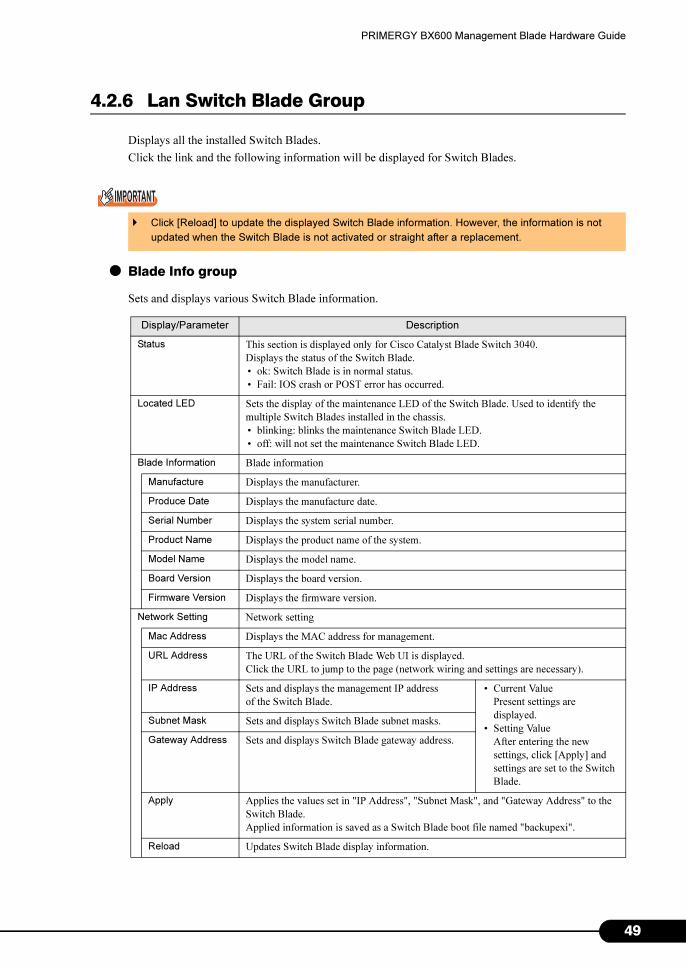
4.2.6 Lan Switch Blade Group
Displays all the installed Switch Blades.
Click the link and the following information will be displayed for Switch Blades.
● Blade Info group
Sets and displays various Switch Blade information.
� Click [Reload] to update the displayed Switch Blade information. However, the information is not
updated when the Switch Blade is not activated or straight after a replacement.
Display/Parameter Description
Status This section is displayed only for Cisco Catalyst Blade Switch 3040.
Displays the status of the Switch Blade.
• ok: Switch Blade is in normal status.
• Fail: IOS crash or POST error has occurred.
Located LED Sets the display of the maintenance LED of the Switch Blade. Used to identify the
multiple Switch Blades installed in the chassis.
• blinking: blinks the maintenance Switch Blade LED.
• off: will not set the maintenance Switch Blade LED.
Blade Information Blade information
Manufacture Displays the manufacturer.
Produce Date Displays the manufacture date.
Serial Number Displays the system serial number.
Product Name Displays the product name of the system.
Model Name Displays the model name.
Board Version Displays the board version.
Firmware Version Displays the firmware version.
Network Setting Network setting
Mac Address Displays the MAC address for management.
URL Address The URL of the Switch Blade Web UI is displayed.
Click the URL to jump to the page (network wiring and settings are necessary).
IP Address Sets and displays the management IP address
of the Switch Blade.
• Current Value
Present settings are
displayed.
• Setting Value
After entering the new
settings, click [Apply] and
settings are set to the Switch
Blade.
Subnet Mask Sets and displays Switch Blade subnet masks.
Gateway Address Sets and displays Switch Blade gateway address.
Apply Applies the values set in "IP Address", "Subnet Mask", and "Gateway Address" to the
Switch Blade.
Applied information is saved as a Switch Blade boot file named "backupexi".
Reload Updates Switch Blade display information.
49
5
Chapter 4 Web UI
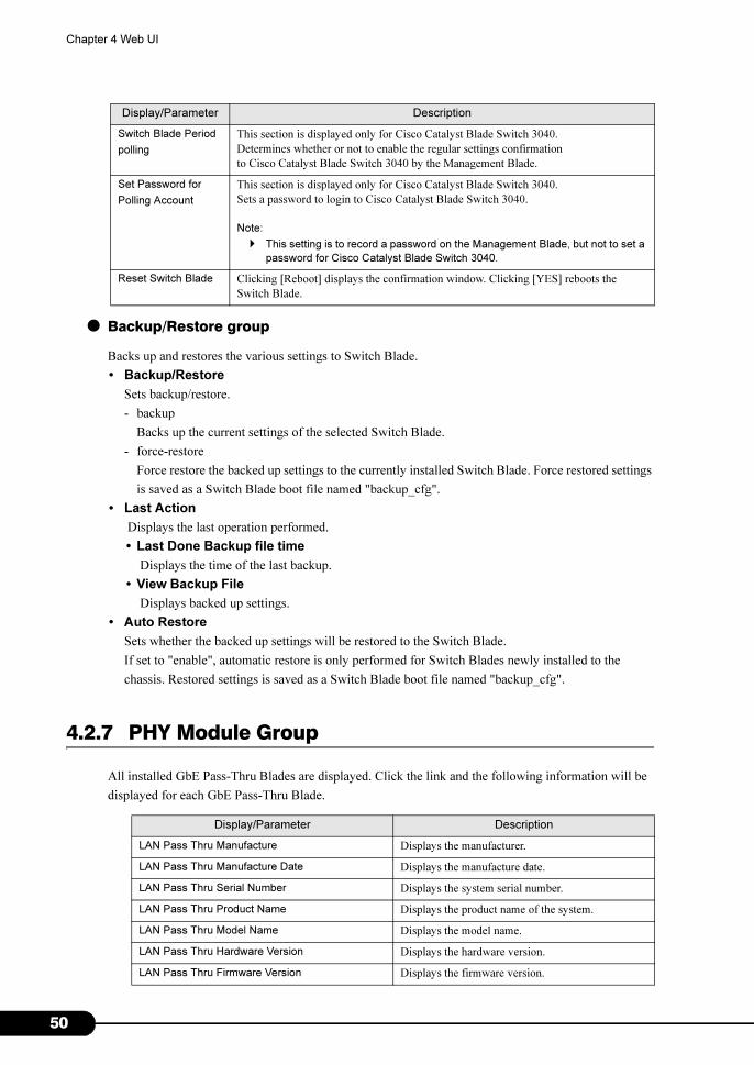
● Backup/Restore group
Backs up and restores the various settings to Switch Blade.
• Backup/Restore
Sets backup/restore.
- backup
Backs up the current settings of the selected Switch Blade.
- force-restore
Force restore the backed up settings to the currently installed Switch Blade. Force restored settings
is saved as a Switch Blade boot file named "backup_cfg".
• Last Action
Displays the last operation performed.
• Last Done Backup file time
Displays the time of the last backup.
• View Backup File
Displays backed up settings.
• Auto Restore
Sets whether the backed up settings will be restored to the Switch Blade.
If set to "enable", automatic restore is only performed for Switch Blades newly installed to the
chassis. Restored settings is saved as a Switch Blade boot file named "backup_cfg".
4.2.7 PHY Module Group
All installed GbE Pass-Thru Blades are displayed. Click the link and the following information will be
displayed for each GbE Pass-Thru Blade.
Switch Blade Period
polling
This section is displayed only for Cisco Catalyst Blade Switch 3040.
Determines whether or not to enable the regular settings confirmation
to Cisco Catalyst Blade Switch 3040 by the Management Blade.
Set Password for
Polling Account
This section is displayed only for Cisco Catalyst Blade Switch 3040.
Sets a password to login to Cisco Catalyst Blade Switch 3040.
Note:
� This setting is to record a password on the Management Blade, but not to set a
password for Cisco Catalyst Blade Switch 3040.
Reset Switch Blade Clicking [Reboot] displays the confirmation window. Clicking [YES] reboots the
Switch Blade.
Display/Parameter Description
LAN Pass Thru Manufacture Displays the manufacturer.
LAN Pass Thru Manufacture Date Displays the manufacture date.
LAN Pass Thru Serial Number Displays the system serial number.
LAN Pass Thru Product Name Displays the product name of the system.
LAN Pass Thru Model Name Displays the model name.
LAN Pass Thru Hardware Version Displays the hardware version.
LAN Pass Thru Firmware Version Displays the firmware version.
Display/Parameter Description
0
PRIMERGY BX600 Management Blade Hardware Guide
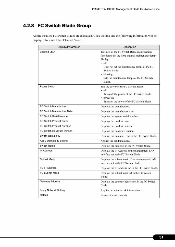
4.2.8 FC Switch Blade Group
All the installed FC Switch Blades are displayed. Click the link and the following information will be
displayed for each Fibre Channel Switch.
Display/Parameter Description
Located LED This acts as the FC Switch Blade identification
function to set the fibre channel maintenance lamp
display.
• off
Does not set the maintenance lamps of the FC
Switch Blade.
• blinking
Sets the maintenance lamps of the FC Switch
Blade.
Power Switch Sets the power of the FC Switch Blade.
• off
Turns off the power of the FC Switch Blade.
• power on
Turns on the power of the FC Switch Blade.
FC Switch Manufacture Displays the manufacturer.
FC Switch Manufacture Date Displays the manufacture date.
FC Switch Serial Number Displays the system serial number.
FC Switch Product Name Displays the product name.
FC Switch Product Number Displays the product number.
FC Switch Hardware Version Displays the hardware version.
Switch Domain ID Displays the domain ID set in the FC Switch Blade.
Apply Domain ID Setting Applies the set domain ID.
Switch Name Displays the name set in the FC Switch Blade.
IP Address Displays the IP Address of the management LAN
interface set in the FC Switch Blade.
Subnet Mask Displays the subnet mask of the management LAN
interface set in the FC Switch Blade.
FC IP Address Displays the IP Address set in the FC Switch Blade.
FC Subnet Mask Displays the subnet mask set in the FC Switch
Blade.
Gateway Address Displays the gateway address set in the FC Switch
Blade.
Apply Network Setting Applies the set network information.
Reload Reloads the set contents.
51
5
Chapter 4 Web UI
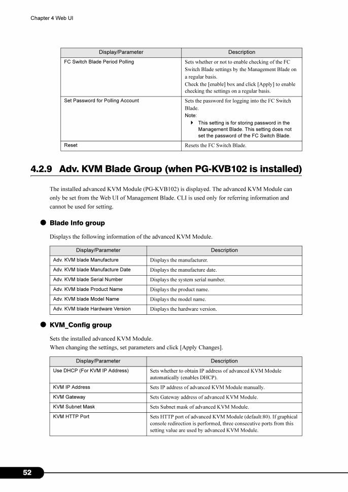
4.2.9 Adv. KVM Blade Group (when PG-KVB102 is installed)
The installed advanced KVM Module (PG-KVB102) is displayed. The advanced KVM Module can
only be set from the Web UI of Management Blade. CLI is used only for referring information and
cannot be used for setting.
● Blade Info group
Displays the following information of the advanced KVM Module.
● KVM_Config group
Sets the installed advanced KVM Module.
When changing the settings, set parameters and click [Apply Changes].
FC Switch Blade Period Polling Sets whether or not to enable checking of the FC
Switch Blade settings by the Management Blade on
a regular basis.
Check the [enable] box and click [Apply] to enable
checking the settings on a regular basis.
Set Password for Polling Account Sets the password for logging into the FC Switch
Blade.
Note:
� This setting is for storing password in the
Management Blade. This setting does not
set the password of the FC Switch Blade.
Reset Resets the FC Switch Blade.
Display/Parameter Description
Adv. KVM blade Manufacture Displays the manufacturer.
Adv. KVM blade Manufacture Date Displays the manufacture date.
Adv. KVM blade Serial Number Displays the system serial number.
Adv. KVM blade Product Name Displays the product name.
Adv. KVM blade Model Name Displays the model name.
Adv. KVM blade Hardware Version Displays the hardware version.
Display/Parameter Description
Use DHCP (For KVM IP Address) Sets whether to obtain IP address of advanced KVM Module
automatically (enables DHCP).
KVM IP Address Sets IP address of advanced KVM Module manually.
KVM Gateway Sets Gateway address of advanced KVM Module.
KVM Subnet Mask Sets Subnet mask of advanced KVM Module.
KVM HTTP Port Sets HTTP port of advanced KVM Module (default:80). If graphical
console redirection is performed, three consecutive ports from this
setting value are used by advanced KVM Module.
Display/Parameter Description
2
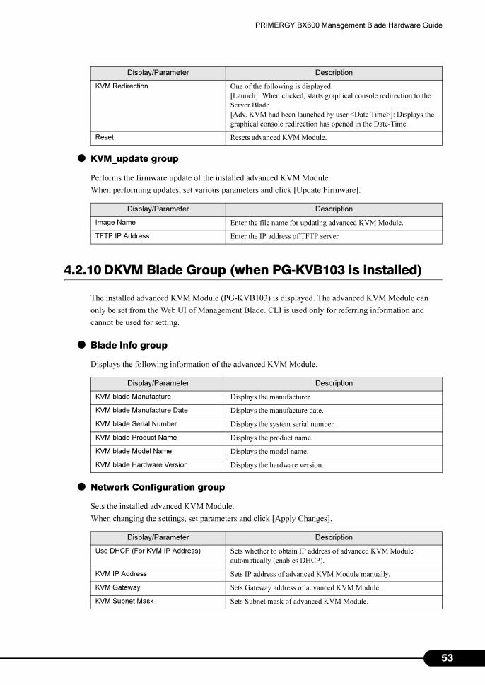
PRIMERGY BX600 Management Blade Hardware Guide
● KVM_update group
Performs the firmware update of the installed advanced KVM Module.
When performing updates, set various parameters and click [Update Firmware].
4.2.10 DKVM Blade Group (when PG-KVB103 is installed)
The installed advanced KVM Module (PG-KVB103) is displayed. The advanced KVM Module can
only be set from the Web UI of Management Blade. CLI is used only for referring information and
cannot be used for setting.
● Blade Info group
Displays the following information of the advanced KVM Module.
● Network Configuration group
Sets the installed advanced KVM Module.
When changing the settings, set parameters and click [Apply Changes].
KVM Redirection One of the following is displayed.
[Launch]: When clicked, starts graphical console redirection to the
Server Blade.
[Adv. KVM had been launched by user <Date Time>]: Displays the
graphical console redirection has opened in the Date-Time.
Reset Resets advanced KVM Module.
Display/Parameter Description
Image Name Enter the file name for updating advanced KVM Module.
TFTP IP Address Enter the IP address of TFTP server.
Display/Parameter Description
KVM blade Manufacture Displays the manufacturer.
KVM blade Manufacture Date Displays the manufacture date.
KVM blade Serial Number Displays the system serial number.
KVM blade Product Name Displays the product name.
KVM blade Model Name Displays the model name.
KVM blade Hardware Version Displays the hardware version.
Display/Parameter Description
Use DHCP (For KVM IP Address) Sets whether to obtain IP address of advanced KVM Module
automatically (enables DHCP).
KVM IP Address Sets IP address of advanced KVM Module manually.
KVM Gateway Sets Gateway address of advanced KVM Module.
KVM Subnet Mask Sets Subnet mask of advanced KVM Module.
Display/Parameter Description
53
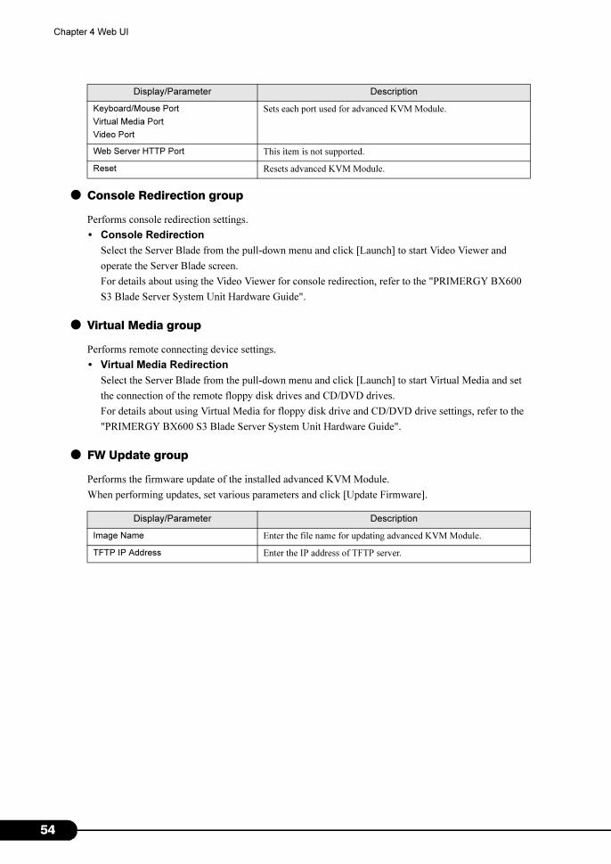
5
Chapter 4 Web UI
● Console Redirection group
Performs console redirection settings.
• Console Redirection
Select the Server Blade from the pull-down menu and click [Launch] to start Video Viewer and
operate the Server Blade screen.
For details about using the Video Viewer for console redirection, refer to the "PRIMERGY BX600
S3 Blade Server System Unit Hardware Guide".
● Virtual Media group
Performs remote connecting device settings.
• Virtual Media Redirection
Select the Server Blade from the pull-down menu and click [Launch] to start Virtual Media and set
the connection of the remote floppy disk drives and CD/DVD drives.
For details about using Virtual Media for floppy disk drive and CD/DVD drive settings, refer to the
"PRIMERGY BX600 S3 Blade Server System Unit Hardware Guide".
● FW Update group
Performs the firmware update of the installed advanced KVM Module.
When performing updates, set various parameters and click [Update Firmware].
Keyboard/Mouse Port
Virtual Media Port
Video Port
Sets each port used for advanced KVM Module.
Web Server HTTP Port This item is not supported.
Reset Resets advanced KVM Module.
Display/Parameter Description
Image Name Enter the file name for updating advanced KVM Module.
TFTP IP Address Enter the IP address of TFTP server.
Display/Parameter Description
4
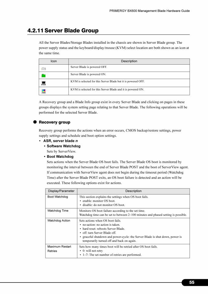
PRIMERGY BX600 Management Blade Hardware Guide
4.2.11 Server Blade Group
All the Server Blades/Storage Blades installed in the chassis are shown in Server Blade group. The
power supply status and the keyboard/display/mouse (KVM) select location are both shown as an icon at
the same time.
A Recovery group and a Blade Info group exist in every Server Blade and clicking on pages in these
groups displays the system setting page relating to that Server Blade. The following operations will be
performed for the selected Server Blade.
● Recovery group
Recovery group performs the actions when an error occurs, CMOS backup/restore settings, power
supply settings and schedule and boot option settings.
• ASR, server blade n
• Software Watchdog
Sets by ServerView.
• Boot Watchdog
Sets actions when the Server Blade OS boot fails. The Server Blade OS boot is monitored by
monitoring the interval between the end of Server Blade POST and the boot of ServerView agent.
If communication with ServerView agent does not begin during the timeout period (Watchdog
Time) after the Server Blade POST exits, an OS boot failure is detected and an action will be
executed. These following options exist for actions.
Icon Description
Server Blade is powered OFF.
Server Blade is powered ON.
KVM is selected for this Server Blade but it is powered OFF.
KVM is selected for this Server Blade and it is powered ON.
Display/Parameter Description
Boot Watchdog This section explains the settings when OS boot fails.
• enable: monitor OS boot.
• disable: do not monitor OS boot.
Watchdog Time Monitors OS boot failure according to the set time.
Watchdog time can be set to between 2–100 minutes and phased setting is possible.
Watchdog Action Sets actions when OS boot fails.
• no-action: no action is taken.
• hard reset: reboots Server Blade.
• off: turn Server Blade off.
• graceful shutdown and power-cycle: the Server Blade is shut down, power is
temporarily turned off and back on again.
Maximum Restart
Retries
Sets how many times boot will be retried after OS boot fails.
• 0: will not retry
• 1–7: The set number of retries are performed.
55
5
Chapter 4 Web UI
� The "OS Boot Monitoring" function can also be enabled or disabled from ServerView.
• Auto Configuration, server blade n
• Server Blade n System CMOS Configuration Backup/Restore
n indicates the installed slot number.
Performs the backup and restore of CMOS information specified by the BIOS setup utility of the
Server Blade.
After turning on the Server Blade, operations cannot be performed until POST ends. In this case
"Not ready to backup/restore, now!!" is displayed.
• CMOS Backup
Backs up the CMOS settings of BIOS.
� If ServerView is not installed to the Server Blade, be sure to set the "Boot Watchdog" to
"disable". If the setting is "enable", there is a fear that the Server Blade may
automatically turn off or restart improperly.
� Even when ServerView is installed to the Server Blade, When starting the system while
the PRIMERGY Startup Disc or floppy disks for activating hardware configuration tools
is inside, be sure to disable the OS Boot Monitoring function (default settings are
disable).
If you start up the system while the "OS Boot Monitoring" function remains enabled, the
Server Blade may automatically turn off or restart unexpectedly. If the OS Boot
Monitoring function is needed, it should be reset to enabled before resuming normal
server operation.
� When setting this function, refer to "ServerView User's Guide" to fully learn about its
specifications, in order to set it correctly.
� It is necessary to back up the BIOS settings when:
• Using the Server Blade for the first time
• Using the BIOS Setup Utility to make information changes
• Hardware configuration of this server is changed, in specific memory expansion
change
• Updating the BIOS version
� Information that is configured with the BIOS setup utility can be backed up/restored.
BIOS information of the onboard SCSI Array Controller cannot be backed up/ restored.
� Backup/restore results are recorded in the Management Blade event log.
6

PRIMERGY BX600 Management Blade Hardware Guide
• CMOS Restore
Restores the CMOS settings of BIOS.
It is necessary to restart Server Blade to enable the BIOS information. Restart as necessary.
• Power Control, server blade n
• Power Status / Power Switch
Sets Server Blade power supply. When using refer to "6.2 Points to Note about Remote Power OFF
and the Shutdown Function" (�p.139).
- Power on
Turns on the server.
- graceful shutdown and off
Sends an order to shut down the OS to the ServerView agent operating on the Server Blade, and
turn off the power.
- graceful shutdown and power-cycle
Sends an order to shut down the OS to the ServerView agent operating on the Server Blade and
after temporarily turning off, turns on the power again.
- hard reset
Reactivates the Server Blade.
- NMI
Normally, do not select.
� This function cannot be used when the Server Blade that backed up the CMOS
settings and the restore destination Server Blade differs or when the BIOS version
differs.
Display/Parameter Description
CMOS File Displays the CMOS settings file backed up to the Management Blade. "Slot
number: MAC address: Backup date: BIOS version" is attached as the file name.
Select the settings file to be restored.
Restore Policy Sets the conditions (policy) for restoring BIOS CMOS settings to Server Blade.
• smart-restore: stops restore when the MAC address and slot number of the
Server Blade for restoration and the Server Blade which backed up the CMOS
setting file differs.
• force-restore: forcibly restore even if the Server Blade for restoration and the
Server Blade to which backed up the CMOS setting file differs.
IMPORTANT:
� This function cannot be used when the model of the Server Blade that
backed up the CMOS settings and the restore destination Server Blade
differs.
� When using the graceful shutdown function it is necessary to make various settings to
Server Blades. For details, refer to "6.2 Points to Note about Remote Power OFF and
the Shutdown Function" (�p.139). Do not select "graceful shutdown and power-cycle"
when performing operations for Server Blades that are not supported because there is
a fear that unexpected operations such as ACPI shutdown or power off may occur.
57
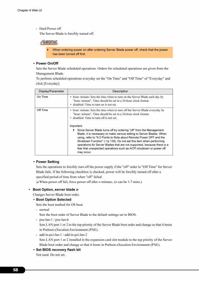
5
Chapter 4 Web UI
- Hard Power off
The Server Blade is forcibly turned off.
• Power On/Off
Sets the Server Blade scheduled operations. Orders for scheduled operations are given from the
Management Blade.
To perform scheduled operations everyday set the "On Time" and "Off Time" of "Everyday" and
click [Everyday].
• Power Setting
Sets the operations to forcibly turn off the power supply if the "off" order in "Off Time" for Server
Blade fails. If the following checkbox is checked, power will be forcibly turned off after a
specified period of time from when "off" failed.
❑ When power off fail, force power off after n minutes. (n can be 1-7 mins.)
• Boot Option, server blade n
Changes Server Blade boot order.
• Boot Option Selected
Sets the boot method for OS boot.
- normal
Sets the boot order of Server Blade to the default settings set in BIOS.
- pxe-lan-1 / pxe-lan-6
Sets LAN port 1 or 2 to the top priority of the Server Blade boot order and change so that it boots
in Preboot eXecution Environment (PXE).
- add-in-pci-lan-1 / add-in-pci-lan-2
Sets LAN port 1 or 2 installed in the expansion card slot module to the top priority of the Server
Blade boot order and change so that it boots in Preboot eXecution Environment (PXE).
• Set BIOS recovery flash bit
Not used. Do not set.
� When ordering power on after ordering Server Blade power off, check that the power
has been turned off first.
Display/Parameter Description
On Time • hour: minute: Sets the time when to turn on the Server Blade each day by
"hour: minute". Time should be set in a 24-hour clock format.
• disabled: Time to turn on is not set.
Off Time • hour: minute: Sets the time when to turn off the Server Blade everyday by
"hour: minute". Time should be set in a 24-hour clock format.
• disabled: Time to turn off is not set.
Important:
� Since Server Blade turns off by ordering "off" from the Management
Blade, it is necessary to make various setting to Server Blades. When
using, refer to "6.2 Points to Note about Remote Power OFF and the
Shutdown Function" (�p.139). Do not set this item when performing
operations for Server Blades that are not supported, because there is a
fear that unexpected operations such as ACPI shutdown or power off
may occur.
8
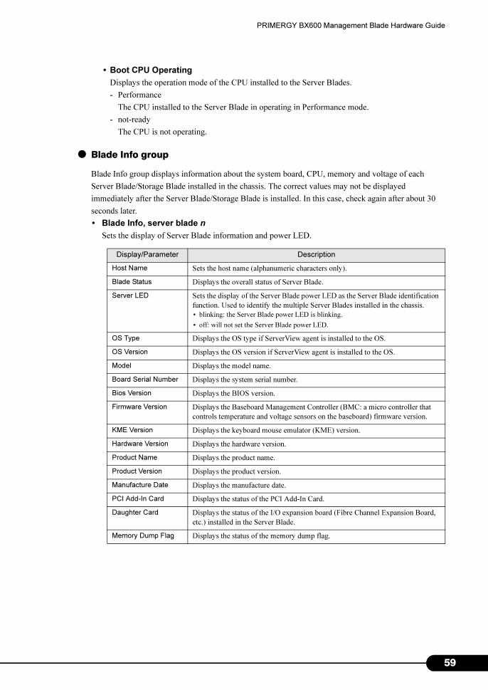
PRIMERGY BX600 Management Blade Hardware Guide
• Boot CPU Operating
Displays the operation mode of the CPU installed to the Server Blades.
- Performance
The CPU installed to the Server Blade in operating in Performance mode.
- not-ready
The CPU is not operating.
● Blade Info group
Blade Info group displays information about the system board, CPU, memory and voltage of each
Server Blade/Storage Blade installed in the chassis. The correct values may not be displayed
immediately after the Server Blade/Storage Blade is installed. In this case, check again after about 30
seconds later.
• Blade Info, server blade n
Sets the display of Server Blade information and power LED.
Display/Parameter Description
Host Name Sets the host name (alphanumeric characters only).
Blade Status Displays the overall status of Server Blade.
Server LED Sets the display of the Server Blade power LED as the Server Blade identification
function. Used to identify the multiple Server Blades installed in the chassis.
• blinking: the Server Blade power LED is blinking.
• off: will not set the Server Blade power LED.
OS Type Displays the OS type if ServerView agent is installed to the OS.
OS Version Displays the OS version if ServerView agent is installed to the OS.
Model Displays the model name.
Board Serial Number Displays the system serial number.
Bios Version Displays the BIOS version.
Firmware Version Displays the Baseboard Management Controller (BMC: a micro controller that
controls temperature and voltage sensors on the baseboard) firmware version.
KME Version Displays the keyboard mouse emulator (KME) version.
Hardware Version Displays the hardware version.
Product Name Displays the product name.
Product Version Displays the product version.
Manufacture Date Displays the manufacture date.
PCI Add-In Card Displays the status of the PCI Add-In Card.
Daughter Card Displays the status of the I/O expansion board (Fibre Channel Expansion Board,
etc.) installed in the Server Blade.
Memory Dump Flag Displays the status of the memory dump flag.
59
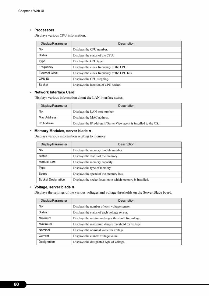
6
Chapter 4 Web UI
• Processors
Displays various CPU information.
• Network Interface Card
Displays various information about the LAN interface status.
• Memory Modules, server blade n
Displays various information relating to memory.
• Voltage, server blade n
Displays the settings of the various voltages and voltage thresholds on the Server Blade board.
Display/Parameter Description
No. Displays the CPU number.
Status Displays the status of the CPU.
Type Displays the CPU type.
Frequency Displays the clock frequency of the CPU.
External Clock Displays the clock frequency of the CPU bus.
CPU ID Displays the CPU stepping.
Socket Displays the location of CPU socket.
Display/Parameter Description
No. Displays the LAN port number.
Mac Address Displays the MAC address.
IP Address Displays the IP address if ServerView agent is installed to the OS.
Display/Parameter Description
No. Displays the memory module number.
Status Displays the status of the memory.
Module Size Displays the memory capacity.
Type Displays the type of memory.
Speed Displays the speed of the memory bus.
Socket Designation Displays the socket location to which memory is installed.
Display/Parameter Description
No Displays the number of each voltage sensor.
Status Displays the status of each voltage sensor.
Minimum Displays the minimum danger threshold for voltage.
Maximum Displays the maximum danger threshold for voltage.
Nominal Displays the nominal value for voltage.
Current Displays the current voltage value.
Designation Displays the designated type of voltage.
0
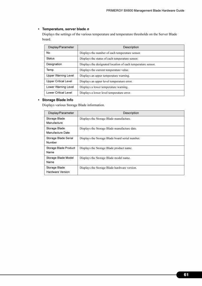
PRIMERGY BX600 Management Blade Hardware Guide
• Temperature, server blade n
Displays the settings of the various temperature and temperature thresholds on the Server Blade
board.
• Storage Blade Info
Displays various Storage Blade information.
Display/Parameter Description
No Displays the number of each temperature sensor.
Status Displays the status of each temperature sensor.
Designation Displays the designated location of each temperature sensor.
Temp. Displays the current temperature value.
Upper Warning Level Displays an upper temperature warning.
Upper Critical Level Displays an upper level temperature error.
Lower Warning Level Displays a lower temperature warning.
Lower Critical Level Displays a lower level temperature error.
Display/Parameter Description
Storage Blade
Manufacture
Displays the Storage Blade manufacture.
Storage Blade
Manufacture Date
Displays the Storage Blade manufacture date.
Storage Blade Serial
Number
Displays the Storage Blade board serial number.
Storage Blade Product
Name
Displays the Storage Blade product name.
Storage Blade Model
Name
Displays the Storage Blade model name.
Storage Blade
Hardware Version
Displays the Storage Blade hardware version.
61

6
Chapter 4 Web UI
2
Chapter 5
CLI
This chapter explains the command line
interface (CLI) which enables the management/
operation of the blade server system in the
Management Blade.
5.1 CLI Connection Methods . . . . . . . . . . . . . . . . . . . . . . . . . 64
5.2 Basic Operations of Each Screen . . . . . . . . . . . . . . . . . . 66
5.3 CLI Login . . . . . . . . . . . . . . . . . . . . . . . . . . . . . . . . . . . . 67
5.4 CLI Menu . . . . . . . . . . . . . . . . . . . . . . . . . . . . . . . . . . . . 69
63
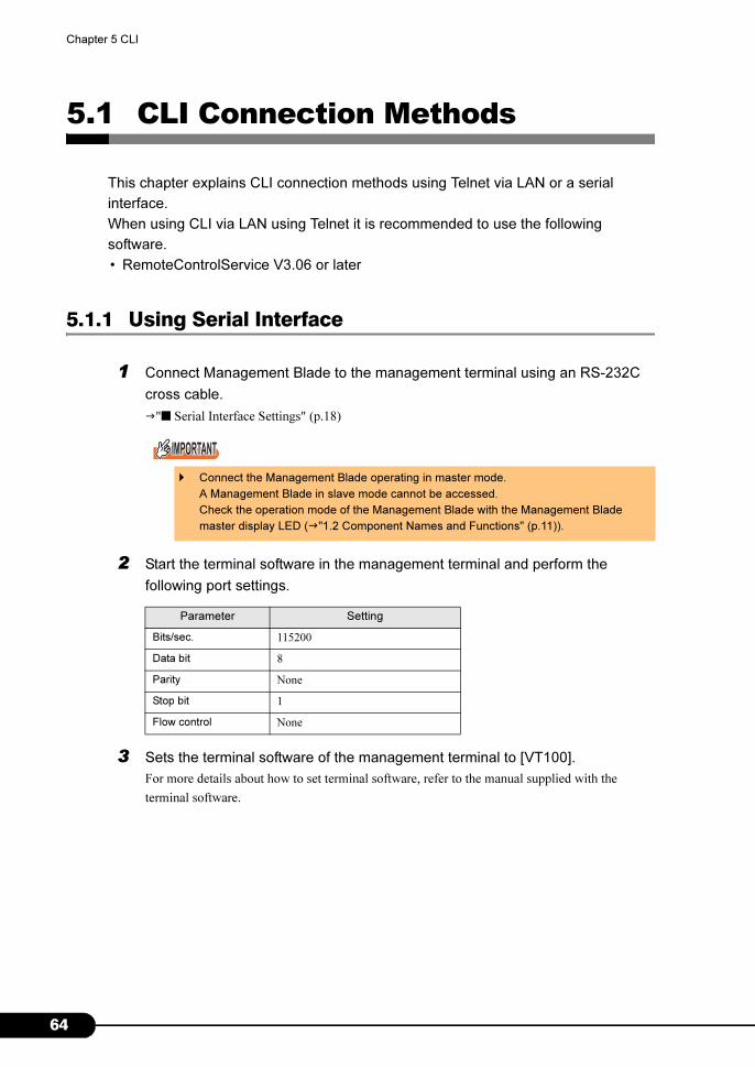
6
Chapter 5 CLI
5.1 CLI Connection Methods
This chapter explains CLI connection methods using Telnet via LAN or a serial
interface.
When using CLI via LAN using Telnet it is recommended to use the following
software.
• RemoteControlService V3.06 or later
5.1.1 Using Serial Interface
1 Connect Management Blade to the management terminal using an RS-232C
cross cable.
�"■ Serial Interface Settings" (p.18)
2 Start the terminal software in the management terminal and perform the
following port settings.
3 Sets the terminal software of the management terminal to [VT100].
For more details about how to set terminal software, refer to the manual supplied with the
terminal software.
� Connect the Management Blade operating in master mode.
A Management Blade in slave mode cannot be accessed.
Check the operation mode of the Management Blade with the Management Blade
master display LED (�"1.2 Component Names and Functions" (p.11)).
Parameter Setting
Bits/sec. 115200
Data bit 8
Parity None
Stop bit 1
Flow control None
4
PRIMERGY BX600 Management Blade Hardware Guide
5.1.2 Using Telnet via LAN Interface
1 Connect Management Blade to the management terminal using a LAN cable.
�"■ LAN Interface Settings" (p.16)
2 Start the Telnet client software in the management terminal and specify the IP
address and port number of the Management Blade to connect the
Management Blade to the management terminal.
(Default value IP address: 192.168.1.1, subnet mask: 255.255.255.0, port number: 3172)
� Telnet only opens one session for Management Blade at a time.
� It is necessary to set Telnet client software to [VT100]. For more details about how to set client
software, refer to the manual supplied with the client software.
65

6
Chapter 5 CLI
5.2 Basic Operations of Each Screen
In the CLI page, if you enter the numbers shown on the screen after "Enter
Selection:" and press [Enter], information can be set and displayed and pages can be
changed.
• When entering setting values, enter the number or letter strings in accordance with the directions
displayed on the screen after the symbol [- - >>].
• If <effect after reboot> is displayed on the screen, it is necessary to restart the Management Blade
after changing settings.
• The items shown as (-) display only and cannot be changed.
• Letter strings can be deleted by pressing [Space] and then pressing [Enter] in the same input window.
• If the time is entered using the 24 hour format, 6:30 am is entered as "06:30" and 6:30 pm is entered
as "18:30".
6
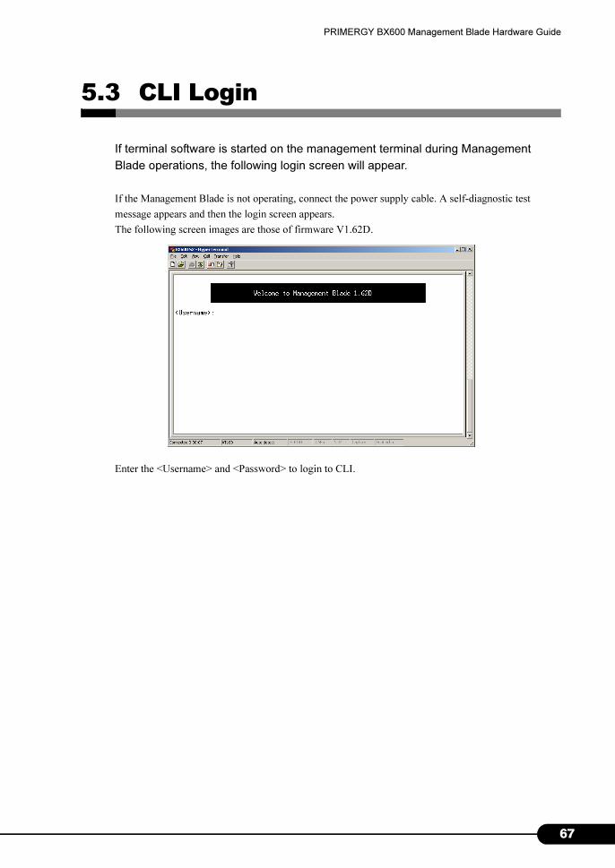
PRIMERGY BX600 Management Blade Hardware Guide
5.3 CLI Login
If terminal software is started on the management terminal during Management
Blade operations, the following login screen will appear.
If the Management Blade is not operating, connect the power supply cable. A self-diagnostic test
message appears and then the login screen appears.
The following screen images are those of firmware V1.62D.
Enter the <Username> and <Password> to login to CLI.
67
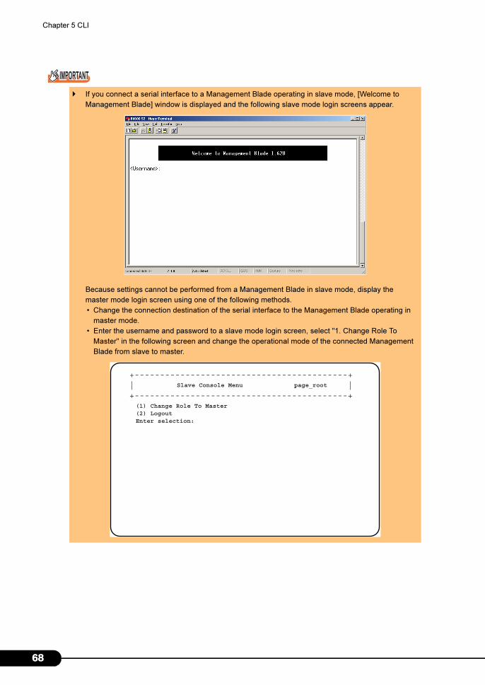
6
Chapter 5 CLI
� If you connect a serial interface to a Management Blade operating in slave mode, [Welcome to
Management Blade] window is displayed and the following slave mode login screens appear.
Because settings cannot be performed from a Management Blade in slave mode, display the
master mode login screen using one of the following methods.
• Change the connection destination of the serial interface to the Management Blade operating in
master mode.
• Enter the username and password to a slave mode login screen, select "1. Change Role To
Master" in the following screen and change the operational mode of the connected Management
Blade from slave to master.
+------------------------------------------+| |+------------------------------------------+
Slave Console Menu page_root
(1) Change Role To Master(2) LogoutEnter selection:
8
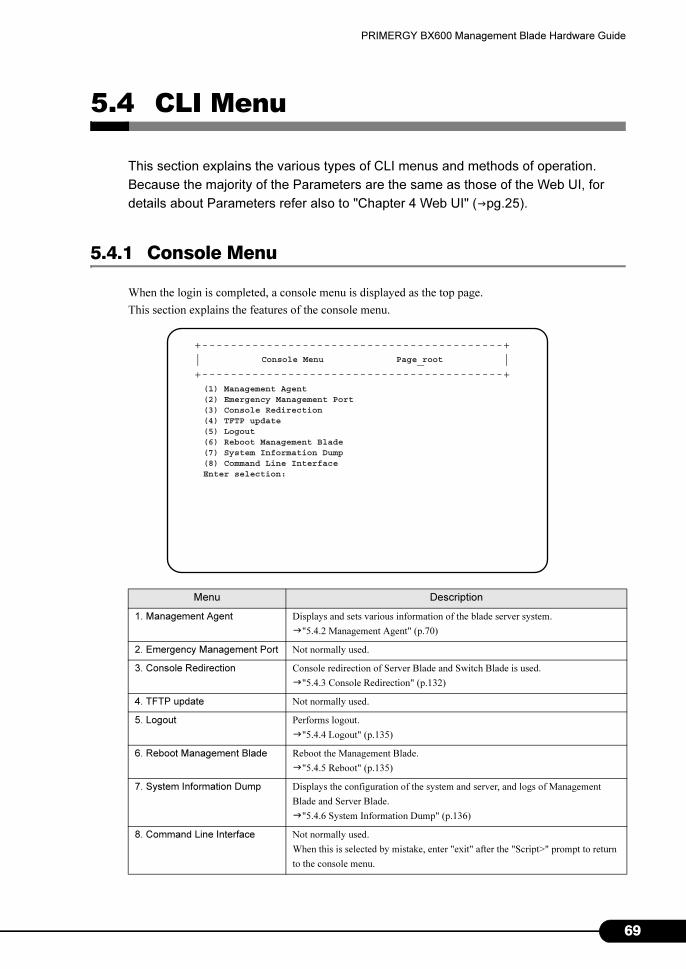
PRIMERGY BX600 Management Blade Hardware Guide
5.4 CLI Menu
This section explains the various types of CLI menus and methods of operation.
Because the majority of the Parameters are the same as those of the Web UI, for
details about Parameters refer also to "Chapter 4 Web UI" (�pg.25).
5.4.1 Console Menu
When the login is completed, a console menu is displayed as the top page.
This section explains the features of the console menu.
Menu Description
1. Management Agent Displays and sets various information of the blade server system.
�"5.4.2 Management Agent" (p.70)
2. Emergency Management Port Not normally used.
3. Console Redirection Console redirection of Server Blade and Switch Blade is used.
�"5.4.3 Console Redirection" (p.132)
4. TFTP update Not normally used.
5. Logout Performs logout.
�"5.4.4 Logout" (p.135)
6. Reboot Management Blade Reboot the Management Blade.
�"5.4.5 Reboot" (p.135)
7. System Information Dump Displays the configuration of the system and server, and logs of Management
Blade and Server Blade.
�"5.4.6 System Information Dump" (p.136)
8. Command Line Interface Not normally used.
When this is selected by mistake, enter "exit" after the "Script>" prompt to return
to the console menu.
Console Menu Page root
(1) Management Agent(2) Emergency Management Port(3) Console Redirection(4) TFTP update(5) Logout(6) Reboot Management Blade(7) System Information Dump(8) Command Line InterfaceEnter selection:
+------------------------------------------+| _ |+------------------------------------------+
69
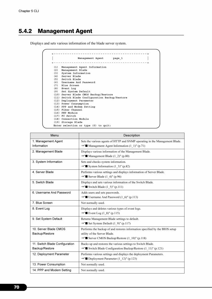
7
Chapter 5 CLI
5.4.2 Management Agent
Displays and sets various information of the blade server system.
Menu Description
1. Management Agent
Information
Sets the various agents of HTTP and SNMP operating in the Management Blade.
�"■ Management Agent Information (1_1)" (p.71)
2. Management Blade Displays various information of the Management Blade.
�"■ Management Blade (1_2)" (p.80)
3. System Information Sets and checks system information.
�"■ System Information (1_3)" (p.82)
4. Server Blade Performs various settings and displays information of Server Blade.
�"■ Server Blade (1_4)" (p.96)
5. Switch Blade Displays and sets various information of the Switch Blade.
�"■ Switch Blade (1_5)" (p.111)
6. Username And Password Adds users and sets passwords.
�"■ Username And Password (1_6)" (p.113)
7. Blue Screen Not normally used.
8. Event Log Displays and deletes various types of event logs.
�"■ Event Log (1_8)" (p.115)
9. Set System Default Returns Management Blade settings to default.
�"■ Set System Default (1_9)" (p.117)
10. Server Blade CMOS
Backup/Restore
Performs the backup of and restores information specified by the BIOS setup
utility of the Server Blade.
�"■ Server CMOS Backup/Restore (1_10)" (p.118)
11. Switch Blade Configuration
Backup/Restore
Backs up and restores the various settings to Switch Blade.
�"■ Switch Blade Configuration Backup/Restore (1_11)" (p.121)
12. Deployment Parameter Performs various settings and displays the deployment Parameters.
�"■ Deployment Parameter (1_12)" (p.123)
13. Power Consumption Not normally used.
14. PPP and Modem Setting Not normally used.
Management Agent page_1
(1) Management Agent Information(2) Management Blade(3) System Information(4) Server Blade(5) Switch Blade(6) Username And Password(7) Blue Screen(8) Event Log(9) Set System Default(10) Server Blade CMOS Backup/Restore(11) Switch Blade Configuration Backup/Restore(12) Deployment Parameter(13) Power Consumption(14) PPP and Modem Setting(15) Fiber Channel(16) PHY Module(17) FC Switch
Enter selection or type (0) to quit:
(18) Connection Module(19) Storage Blade
+------------------------------------------+| |+------------------------------------------+
0
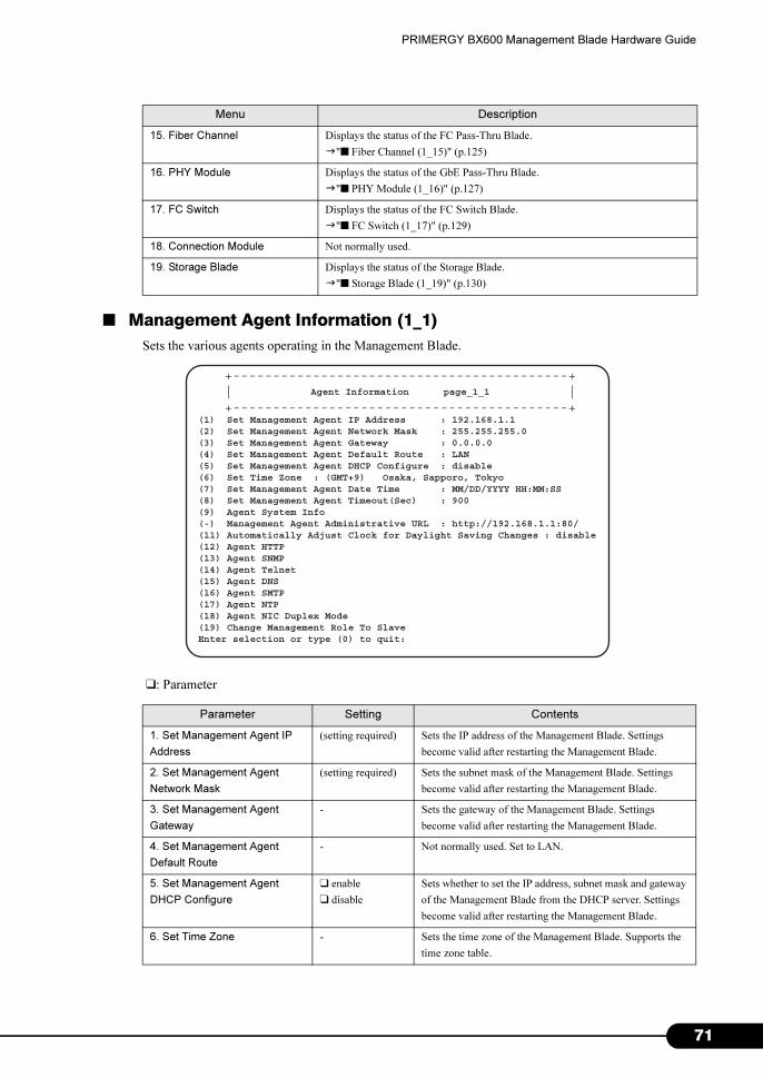
PRIMERGY BX600 Management Blade Hardware Guide
■ Management Agent Information (1_1)
Sets the various agents operating in the Management Blade.
❑: Parameter
15. Fiber Channel Displays the status of the FC Pass-Thru Blade.
�"■ Fiber Channel (1_15)" (p.125)
16. PHY Module Displays the status of the GbE Pass-Thru Blade.
�"■ PHY Module (1_16)" (p.127)
17. FC Switch Displays the status of the FC Switch Blade.
�"■ FC Switch (1_17)" (p.129)
18. Connection Module Not normally used.
19. Storage Blade Displays the status of the Storage Blade.
�"■ Storage Blade (1_19)" (p.130)
Parameter Setting Contents
1. Set Management Agent IP
Address
(setting required) Sets the IP address of the Management Blade. Settings
become valid after restarting the Management Blade.
2. Set Management Agent
Network Mask
(setting required) Sets the subnet mask of the Management Blade. Settings
become valid after restarting the Management Blade.
3. Set Management Agent
Gateway
- Sets the gateway of the Management Blade. Settings
become valid after restarting the Management Blade.
4. Set Management Agent
Default Route
- Not normally used. Set to LAN.
5. Set Management Agent
DHCP Configure
❑ enable
❑ disable
Sets whether to set the IP address, subnet mask and gateway
of the Management Blade from the DHCP server. Settings
become valid after restarting the Management Blade.
6. Set Time Zone - Sets the time zone of the Management Blade. Supports the
time zone table.
Menu Description
(1) Set Management Agent IP Address : 192.168.1.1(2) Set Management Agent Network Mask : 255.255.255.0(3) Set Management Agent Gateway : 0.0.0.0(4) Set Management Agent Default Route : LAN(5) Set Management Agent DHCP Configure : disable(6) Set Time Zone : (GMT+9) Osaka, Sapporo, Tokyo(7) Set Management Agent Date Time : MM/DD/YYYY HH:MM:SS(8) Set Management Agent Timeout(Sec) : 900(9) Agent System Info (-) Management Agent Administrative URL : http://192.168.1.1:80/(11) Automatically Adjust Clock for Daylight Saving Changes : disable(12) Agent HTTP (13) Agent SNMP(14) Agent Telnet(15) Agent DNS(16) Agent SMTP (17) Agent NTP (18) Agent NIC Duplex Mode(19) Change Management Role To SlaveEnter selection or type (0) to quit:
Agent Information page_1_1
+------------------------------------------+| |+------------------------------------------+
71
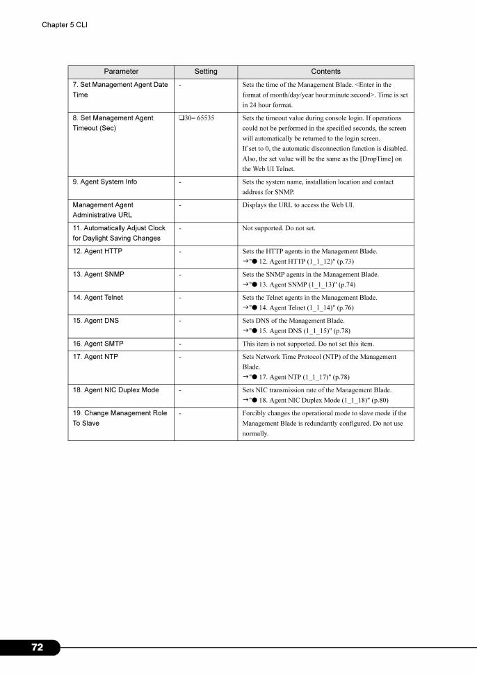
7
Chapter 5 CLI
7. Set Management Agent Date
Time
- Sets the time of the Management Blade. <Enter in the
format of month/day/year hour:minute:second>. Time is set
in 24 hour format.
8. Set Management Agent
Timeout (Sec)
❑30– 65535 Sets the timeout value during console login. If operations
could not be performed in the specified seconds, the screen
will automatically be returned to the login screen.
If set to 0, the automatic disconnection function is disabled.
Also, the set value will be the same as the [DropTime] on
the Web UI Telnet.
9. Agent System Info - Sets the system name, installation location and contact
address for SNMP.
Management Agent
Administrative URL
- Displays the URL to access the Web UI.
11. Automatically Adjust Clock
for Daylight Saving Changes
- Not supported. Do not set.
12. Agent HTTP - Sets the HTTP agents in the Management Blade.
�"● 12. Agent HTTP (1_1_12)" (p.73)
13. Agent SNMP - Sets the SNMP agents in the Management Blade.
�"● 13. Agent SNMP (1_1_13)" (p.74)
14. Agent Telnet - Sets the Telnet agents in the Management Blade.
�"● 14. Agent Telnet (1_1_14)" (p.76)
15. Agent DNS - Sets DNS of the Management Blade.
�"● 15. Agent DNS (1_1_15)" (p.78)
16. Agent SMTP - This item is not supported. Do not set this item.
17. Agent NTP - Sets Network Time Protocol (NTP) of the Management
Blade.
�"● 17. Agent NTP (1_1_17)" (p.78)
18. Agent NIC Duplex Mode - Sets NIC transmission rate of the Management Blade.
�"● 18. Agent NIC Duplex Mode (1_1_18)" (p.80)
19. Change Management Role
To Slave
- Forcibly changes the operational mode to slave mode if the
Management Blade is redundantly configured. Do not use
normally.
Parameter Setting Contents
2
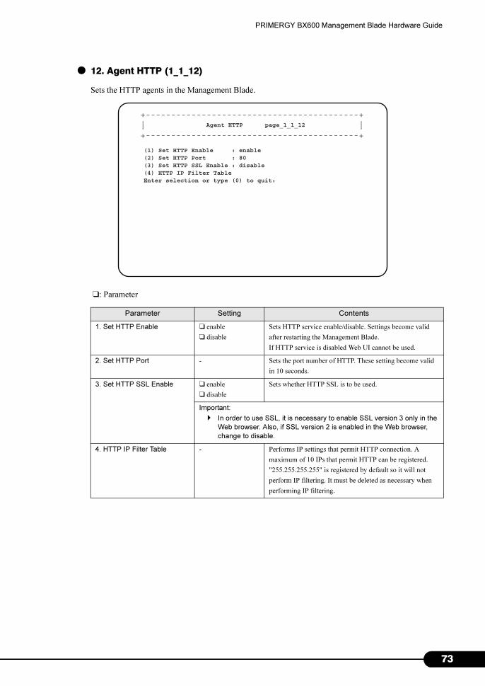
PRIMERGY BX600 Management Blade Hardware Guide
● 12. Agent HTTP (1_1_12)
Sets the HTTP agents in the Management Blade.
❑: Parameter
Parameter Setting Contents
1. Set HTTP Enable ❑ enable
❑ disable
Sets HTTP service enable/disable. Settings become valid
after restarting the Management Blade.
If HTTP service is disabled Web UI cannot be used.
2. Set HTTP Port - Sets the port number of HTTP. These setting become valid
in 10 seconds.
3. Set HTTP SSL Enable ❑ enable
❑ disable
Sets whether HTTP SSL is to be used.
Important:
� In order to use SSL, it is necessary to enable SSL version 3 only in the
Web browser. Also, if SSL version 2 is enabled in the Web browser,
change to disable.
4. HTTP IP Filter Table - Performs IP settings that permit HTTP connection. A
maximum of 10 IPs that permit HTTP can be registered.
"255.255.255.255" is registered by default so it will not
perform IP filtering. It must be deleted as necessary when
performing IP filtering.
+------------------------------------------+| |+------------------------------------------+
Agent HTTP page_1_1_12
(1) Set HTTP Enable : enable(2) Set HTTP Port : 80(3) Set HTTP SSL Enable : disable(4) HTTP IP Filter TableEnter selection or type (0) to quit:
73
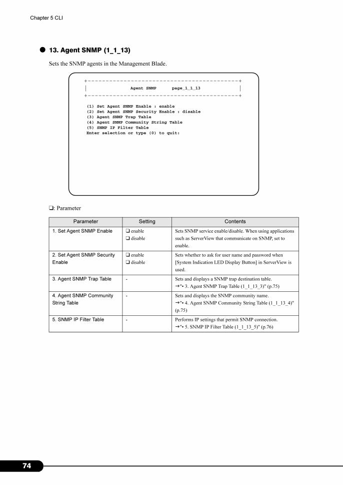
7
Chapter 5 CLI
● 13. Agent SNMP (1_1_13)
Sets the SNMP agents in the Management Blade.
❑: Parameter
Parameter Setting Contents
1. Set Agent SNMP Enable ❑ enable
❑ disable
Sets SNMP service enable/disable. When using applications
such as ServerView that communicate on SNMP, set to
enable.
2. Set Agent SNMP Security
Enable
❑ enable
❑ disable
Sets whether to ask for user name and password when
[System Indication LED Display Button] in ServerView is
used.
3. Agent SNMP Trap Table - Sets and displays a SNMP trap destination table.
�"• 3. Agent SNMP Trap Table (1_1_13_3)" (p.75)
4. Agent SNMP Community
String Table
- Sets and displays the SNMP community name.
�"• 4. Agent SNMP Community String Table (1_1_13_4)"
(p.75)
5. SNMP IP Filter Table - Performs IP settings that permit SNMP connection.
�"• 5. SNMP IP Filter Table (1_1_13_5)" (p.76)
+------------------------------------------+| |+------------------------------------------+
Agent SNMP page_1_1_13
(1) Set Agent SNMP Enable : enable(2) Set Agent SNMP Security Enable : disable(3) Agent SNMP Trap Table(4) Agent SNMP Community String Table(5) SNMP IP Filter TableEnter selection or type (0) to quit:
4
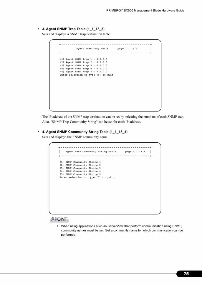
PRIMERGY BX600 Management Blade Hardware Guide
• 3. Agent SNMP Trap Table (1_1_13_3)
Sets and displays a SNMP trap destination table.
The IP address of the SNMP trap destination can be set by selecting the numbers of each SNMP trap.
Also, "SNMP Trap Community String" can be set for each IP address.
• 4. Agent SNMP Community String Table (1_1_13_4)
Sets and displays the SNMP community name.
� When using applications such as ServerView that perform communication using SNMP,
community names must be set. Set a community name for which communication can be
performed.
+------------------------------------------+| |+------------------------------------------+
Agent SNMP Trap Table page_1_1_13_3
(1) Agent SNMP Trap 1 : 0.0.0.0(2) Agent SNMP Trap 2 : 0.0.0.0(3) Agent SNMP Trap 3 : 0.0.0.0(4) Agent SNMP Trap 4 : 0.0.0.0(5) Agent SNMP Trap 5 : 0.0.0.0Enter selection or type (0) to quit:
+------------------------------------------+| |+------------------------------------------+
Agent SNMP Community String Table page_1_1_13_4
(1) SNMP Community String 1 :(2) SNMP Community String 2 :(3) SNMP Community String 3 :(4) SNMP Community String 4 :(5) SNMP Community String 5 :Enter selection or type (0) to quit:
75
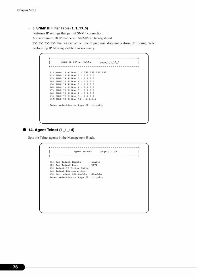
7
Chapter 5 CLI
• 5. SNMP IP Filter Table (1_1_13_5)
Performs IP settings that permit SNMP connection.
A maximum of 10 IP that permit SNMP can be registered.
255.255.255.255, that was set at the time of purchase, does not perform IP filtering. When
performing IP filtering, delete it as necessary.
● 14. Agent Telnet (1_1_14)
Sets the Telnet agents in the Management Blade.
+------------------------------------------+| |+------------------------------------------+
SNMP IP Filter Table page_1_1_13_5
(1) SNMP IP Filter 1 : 255.255.255.255(2) SNMP IP Filter 2 : 0.0.0.0(3) SNMP IP Filter 3 : 0.0.0.0(4) SNMP IP Filter 4 : 0.0.0.0(5) SNMP IP Filter 5 : 0.0.0.0(6) SNMP IP Filter 6 : 0.0.0.0(7) SNMP IP Filter 7 : 0.0.0.0(8) SNMP IP Filter 8 : 0.0.0.0(9) SNMP IP Filter 9 : 0.0.0.0(10)SNMP IP Filter 10 : 0.0.0.0
Enter selection or type (0) to quit:
+------------------------------------------+| |+------------------------------------------+
Agent TELNET page_1_1_14
(1) Set Telnet Enable : enable(2) Set Telnet Port : 3172(3) Telnet IP Filter Table(4) Telnet Disconnection(5) Set telnet SSL Enable : disableEnter selection or type (0) to quit:
6
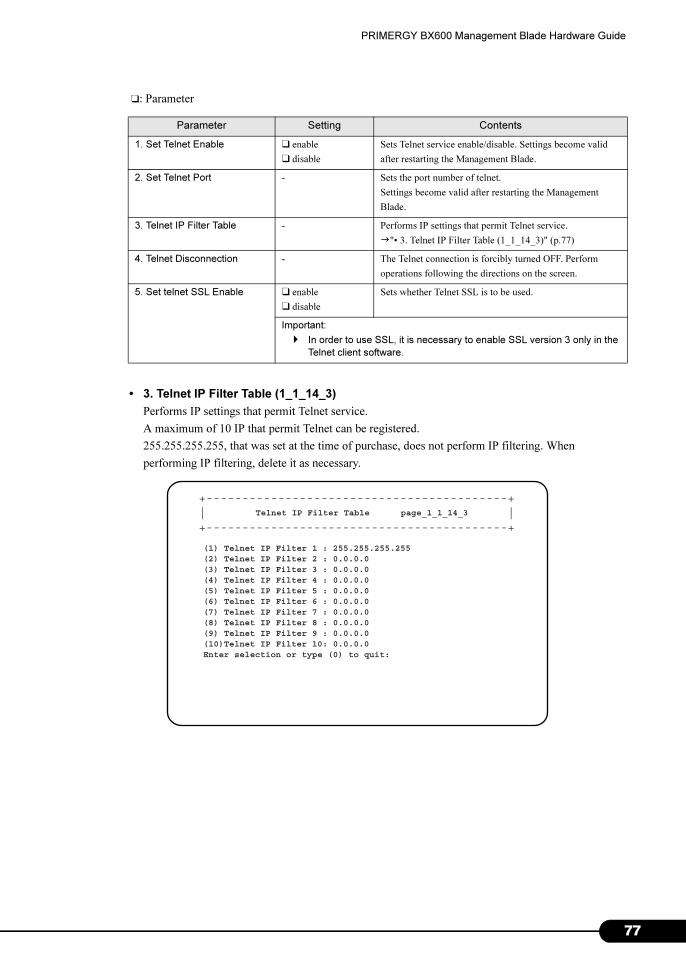
PRIMERGY BX600 Management Blade Hardware Guide
❑: Parameter
• 3. Telnet IP Filter Table (1_1_14_3)
Performs IP settings that permit Telnet service.
A maximum of 10 IP that permit Telnet can be registered.
255.255.255.255, that was set at the time of purchase, does not perform IP filtering. When
performing IP filtering, delete it as necessary.
Parameter Setting Contents
1. Set Telnet Enable ❑ enable
❑ disable
Sets Telnet service enable/disable. Settings become valid
after restarting the Management Blade.
2. Set Telnet Port - Sets the port number of telnet.
Settings become valid after restarting the Management
Blade.
3. Telnet IP Filter Table - Performs IP settings that permit Telnet service.
�"• 3. Telnet IP Filter Table (1_1_14_3)" (p.77)
4. Telnet Disconnection - The Telnet connection is forcibly turned OFF. Perform
operations following the directions on the screen.
5. Set telnet SSL Enable ❑ enable
❑ disable
Sets whether Telnet SSL is to be used.
Important:
� In order to use SSL, it is necessary to enable SSL version 3 only in the
Telnet client software.
+------------------------------------------+| |+------------------------------------------+
Telnet IP Filter Table page_1_1_14_3
(1) Telnet IP Filter 1 : 255.255.255.255(2) Telnet IP Filter 2 : 0.0.0.0(3) Telnet IP Filter 3 : 0.0.0.0(4) Telnet IP Filter 4 : 0.0.0.0(5) Telnet IP Filter 5 : 0.0.0.0(6) Telnet IP Filter 6 : 0.0.0.0(7) Telnet IP Filter 7 : 0.0.0.0(8) Telnet IP Filter 8 : 0.0.0.0(9) Telnet IP Filter 9 : 0.0.0.0(10)Telnet IP Filter 10: 0.0.0.0Enter selection or type (0) to quit:
77
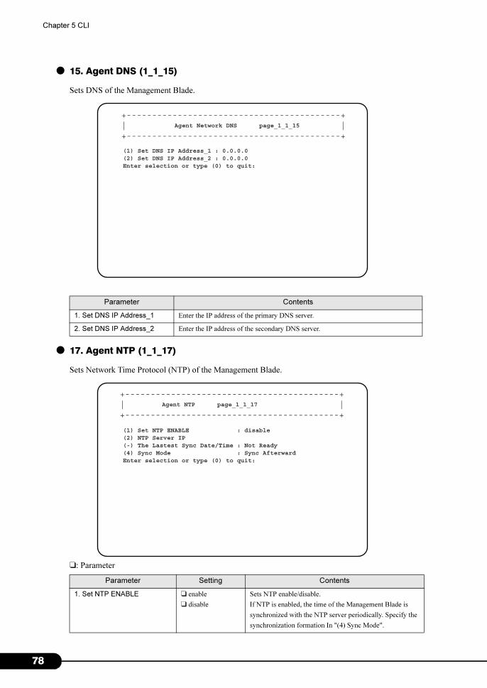
7
Chapter 5 CLI
● 15. Agent DNS (1_1_15)
Sets DNS of the Management Blade.
● 17. Agent NTP (1_1_17)
Sets Network Time Protocol (NTP) of the Management Blade.
❑: Parameter
Parameter Contents
1. Set DNS IP Address_1 Enter the IP address of the primary DNS server.
2. Set DNS IP Address_2 Enter the IP address of the secondary DNS server.
Parameter Setting Contents
1. Set NTP ENABLE ❑ enable
❑ disable
Sets NTP enable/disable.
If NTP is enabled, the time of the Management Blade is
synchronized with the NTP server periodically. Specify the
synchronization formation In "(4) Sync Mode".
+------------------------------------------+| |+------------------------------------------+
Agent Network DNS page_1_1_15
(1) Set DNS IP Address_1 : 0.0.0.0(2) Set DNS IP Address_2 : 0.0.0.0Enter selection or type (0) to quit:
+------------------------------------------+| |+------------------------------------------+
Agent NTP page_1_1_17
(1) Set NTP ENABLE : disable(2) NTP Server IP(-) The Lastest Sync Date/Time : Not Ready(4) Sync Mode : Sync AfterwardEnter selection or type (0) to quit:
8
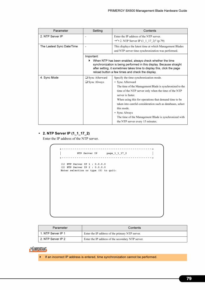
PRIMERGY BX600 Management Blade Hardware Guide
• 2. NTP Server IP (1_1_17_2)
Enter the IP address of the NTP server.
2. NTP Server IP - Enter the IP address of the NTP server.
�"• 2. NTP Server IP (1_1_17_2)" (p.79)
The Lastest Sync Date/Time - This displays the latest time at which Management Blades
and NTP server time synchronization was performed.
Important:
� When NTP has been enabled, always check whether the time
synchronization is being performed in this display. Because straight
after setting, it sometimes takes time to display this, click the page
reload button a few times and check the display.
4. Sync Mode ❑ Sync Afterward
❑ Sync Always
Specify the time synchronization mode.
• Sync Afterward
The time of the Management Blade is synchronized to the
time of the NTP server only when the time of the NTP
server is faster.
When using this for operations that demand time to be
taken into careful consideration such as databases, select
this mode.
• Sync Always
The time of the Management Blade is synchronized with
the NTP server every 15 minutes.
Parameter Contents
1. NTP Server IP 1 Enter the IP address of the primary NTP server.
2. NTP Server IP 2 Enter the IP address of the secondary NTP server.
� If an incorrect IP address is entered, time synchronization cannot be performed.
Parameter Setting Contents
+------------------------------------------+| |+------------------------------------------+
NTP Server IP page_1_1_17_2
(1) NTP Server IP 1 : 0.0.0.0(2) NTP Server IP 2 : 0.0.0.0Enter selection or type (0) to quit:
79
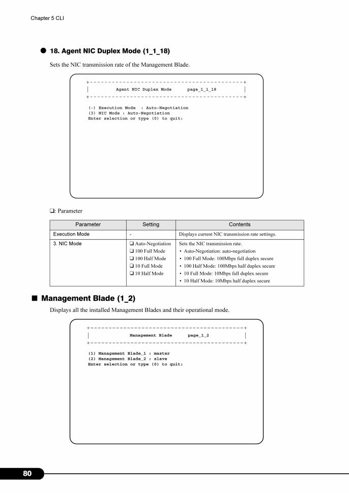
8
Chapter 5 CLI
● 18. Agent NIC Duplex Mode (1_1_18)
Sets the NIC transmission rate of the Management Blade.
❑: Parameter
■ Management Blade (1_2)
Displays all the installed Management Blades and their operational mode.
Parameter Setting Contents
Execution Mode - Displays current NIC transmission rate settings.
3. NIC Mode ❑ Auto-Negotiation
❑ 100 Full Mode
❑ 100 Half Mode
❑ 10 Full Mode
❑ 10 Half Mode
Sets the NIC transmission rate.
• Auto-Negotiation: auto-negotiation
• 100 Full Mode: 100Mbps full duplex secure
• 100 Half Mode: 100Mbps half duplex secure
• 10 Full Mode: 10Mbps full duplex secure
• 10 Half Mode: 10Mbps half duplex secure
+------------------------------------------+| |+------------------------------------------+
Agent NIC Duplex Mode page_1_1_18
(-) Execution Mode : Auto-Negotiation(3) NIC Mode : Auto-NegotiationEnter selection or type (0) to quit:
+------------------------------------------+| |+------------------------------------------+
Management Blade page_1_2
(1) Management Blade_1 : master(2) Management Blade_2 : slaveEnter selection or type (0) to quit:
0
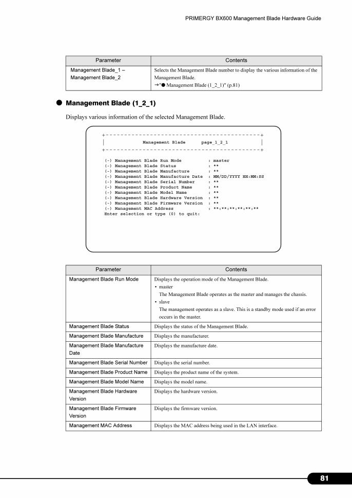
PRIMERGY BX600 Management Blade Hardware Guide
● Management Blade (1_2_1)
Displays various information of the selected Management Blade.
Parameter Contents
Management Blade_1 –
Management Blade_2
Selects the Management Blade number to display the various information of the
Management Blade.
�"● Management Blade (1_2_1)" (p.81)
Parameter Contents
Management Blade Run Mode Displays the operation mode of the Management Blade.
• master
The Management Blade operates as the master and manages the chassis.
• slave
The management operates as a slave. This is a standby mode used if an error
occurs in the master.
Management Blade Status Displays the status of the Management Blade.
Management Blade Manufacture Displays the manufacturer.
Management Blade Manufacture
Date
Displays the manufacture date.
Management Blade Serial Number Displays the serial number.
Management Blade Product Name Displays the product name of the system.
Management Blade Model Name Displays the model name.
Management Blade Hardware
Version
Displays the hardware version.
Management Blade Firmware
Version
Displays the firmware version.
Management MAC Address Displays the MAC address being used in the LAN interface.
+------------------------------------------+| |+------------------------------------------+
Management Blade page_1_2_1
(-) Management Blade Run Mode : master(-) Management Blade Status : **(-) Management Blade Manufacture : **(-) Management Blade Manufacture Date : MM/DD/YYYY HH:MM:SS(-) Management Blade Serial Number : **(-) Management Blade Product Name : **(-) Management Blade Model Name : **(-) Management Blade Hardware Version : **(-) Management Blade Firmware Version : **(-) Management MAC Address : **:**:**:**:**:**Enter selection or type (0) to quit:
81
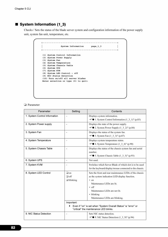
8
Chapter 5 CLI
■ System Information (1_3)
Checks / Sets the status of the blade server system and configuration information of the power supply
unit, system fan unit, temperature, etc.
❑: Parameter
Parameter Setting Contents
1. System Control Information - Displays system information.
�"● 1. System Control Information (1_3_1)" (p.83)
2. System Power supply - Displays the state of the power supply.
�"● 2. System Power Supply (1_3_2)" (p.84)
3. System Fan - Displays the status of the system fan.
�"● 3. System Fan (1_3_3)" (p.87)
4. System Temperature - Displays system temperature status.
�"● 4. System Temperature (1_3_4)" (p.90)
5. System Chassis Table - Displays the status of the chassis system fan and serial
number.
�"● 5. System Chassis Table (1_3_5)" (p.93)
6. System UPS - Not used.
7. System KVM - Switches which Server Blade of which slot is to be used
for the keyboard/display/mouse connected to the chassis.
8. System LED Control ❑ on
❑ off
❑ blinking
Sets the front and rear maintenance LEDs of the chassis
as the system indication LED display function.
• on
Maintenance LEDs are lit.
• off
Maintenance LEDs are not lit.
• blinking
Maintenance LEDs are blinking.
Important:
� Even if "on" is set when "System Overall Status" is "error" or
"critical" the maintenance LED blinks.
9. NIC Status Detection - Sets NIC status detection.
�"● 9. NIC Status Detection (1_3_9)" (p.94)
+------------------------------------------+| |+------------------------------------------+
System Information page_1_3
(1) System Control Information(2) System Power Supply(3) System Fan(4) System Temperature(5) System Chassis Table(6) System UPS(7) System KVM(8) System LED Control : off(9) NIC Status Detection(10) Turn on/off all server bladesEnter selection or type (0) to quit:
2
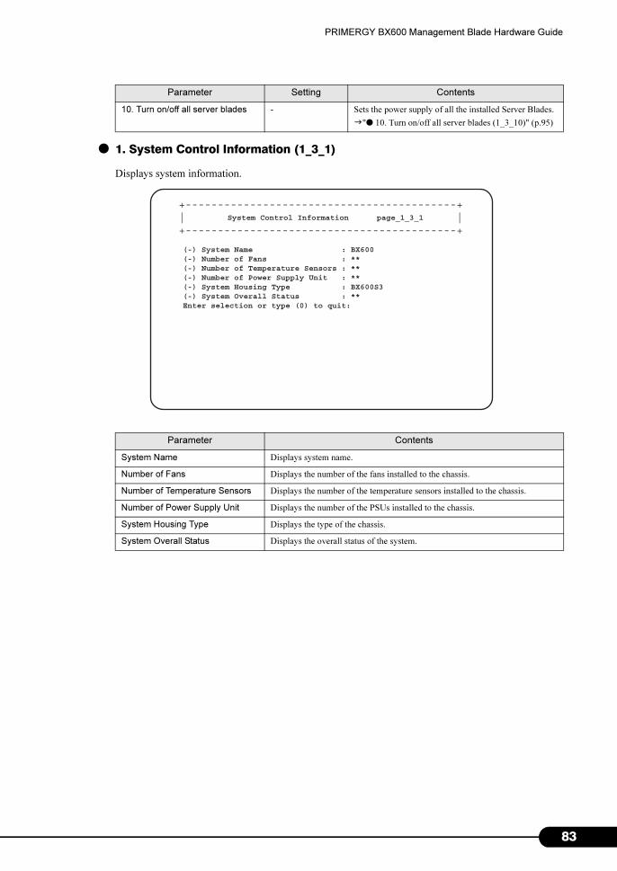
PRIMERGY BX600 Management Blade Hardware Guide
● 1. System Control Information (1_3_1)
Displays system information.
10. Turn on/off all server blades - Sets the power supply of all the installed Server Blades.
�"● 10. Turn on/off all server blades (1_3_10)" (p.95)
Parameter Contents
System Name Displays system name.
Number of Fans Displays the number of the fans installed to the chassis.
Number of Temperature Sensors Displays the number of the temperature sensors installed to the chassis.
Number of Power Supply Unit Displays the number of the PSUs installed to the chassis.
System Housing Type Displays the type of the chassis.
System Overall Status Displays the overall status of the system.
Parameter Setting Contents
+------------------------------------------+| |+------------------------------------------+
System Control Information page_1_3_1
(-) System Name : BX600(-) Number of Fans : **(-) Number of Temperature Sensors : **(-) Number of Power Supply Unit : **(-) System Housing Type : BX600S3(-) System Overall Status : **Enter selection or type (0) to quit:
83
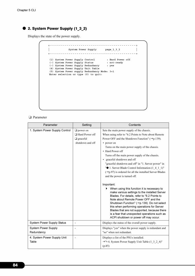
8
Chapter 5 CLI
● 2. System Power Supply (1_3_2)
Displays the state of the power supply.
❑: Parameter
Parameter Setting Contents
1. System Power Supply Control ❑ power on
❑ Hard Power off
❑ graceful
shutdown and off
Sets the main power supply of the chassis.
When using refer to "6.2 Points to Note about Remote
Power OFF and the Shutdown Function" (�p.139).
• power on
Turns on the main power supply of the chassis.
• Hard Power off
Turns off the main power supply of the chassis.
• graceful shutdown and off
"graceful shutdown and off" in "1. Server power" in
"● 1. Server Blade Control Information (1_4_1_1)"
(�p.97) is ordered for all the installed Server Blades
and the power is turned off.
Important:
� When using this function it is necessary to
make various settings to the installed Server
Blades. For details, refer to "6.2 Points to
Note about Remote Power OFF and the
Shutdown Function" (�p.139). Do not select
this when performing operations for Server
Blades that are not supported, because there
is a fear that unexpected operations such as
ACPI shutdown or power off may occur.
System Power Supply Status - Displays the status of the overall power supply.
System Power Supply
Redundancy
- Displays "yes" when the power supply is redundant and
"no" when not redundant.
4. System Power Supply Unit
Table
- Displays a list of the PSUs installed.
�"• 4. System Power Supply Unit Table (1_3_2_4)"
(p.85)
+------------------------------------------+| |+------------------------------------------+
System Power Supply page_1_3_2
(1) System Power Supply Control : Hard Power off(-) System Power Supply Status : not-ready(-) System Power Supply Redundancy : yes(4) System Power Supply Unit Table(5) System Power supply Redundancy Mode: 3+1Enter selection or type (0) to quit:
4
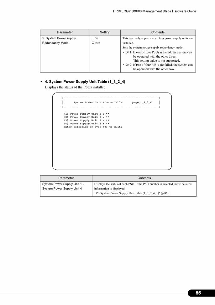
PRIMERGY BX600 Management Blade Hardware Guide
• 4. System Power Supply Unit Table (1_3_2_4)
Displays the status of the PSUs installed.
5. System Power supply
Redundancy Mode
❑ 3+1
❑ 2+2
This item only appears when four power supply units are
installed.
Sets the system power supply redundancy mode.
• 3+1: If one of four PSUs is failed, the system can
be operated with the other three.
This setting value is not supported.
• 2+2: If two of four PSUs are failed, the system can
be operated with the other two.
Parameter Contents
System Power Supply Unit 1 -
System Power Supply Unit 4
Displays the status of each PSU. If the PSU number is selected, more detailed
information is displayed.
�"• System Power Supply Unit Table (1_3_2_4_1)" (p.86)
Parameter Setting Contents
+------------------------------------------+| |+------------------------------------------+
System Power Unit Status Table page_1_3_2_4
(1) Power Supply Unit 1 : **(2) Power Supply Unit 2 : **(3) Power Supply Unit 3 : **(4) Power Supply Unit 4 : **Enter selection or type (0) to quit:
85
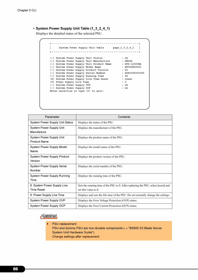
8
Chapter 5 CLI
• System Power Supply Unit Table (1_3_2_4_1)
Displays the detailed status of the selected PSU.
Parameter Contents
System Power Supply Unit Status Displays the status of the PSU.
System Power Supply Unit
Manufacture
Displays the manufacturer of the PSU.
System Power Supply Unit
Product Name
Displays the product name of the PSU.
System Power Supply Model
Name
Displays the model name of the PSU.
System Power Supply Product
Version
Displays the product version of the PSU.
System Power Supply Serial
Number
Displays the serial number of the PSU.
System Power Supply Running
Time
Displays the running time of the PSU.
8. System Power Supply Live
Time Reset
Sets the running time of the PSU to 0. After replacing the PSU, select [reset] and
set this value to 0.
9. Power Supply Live Time Displays and sets the life time of the PSU. Do not normally change the settings.
System Power Supply OVP Displays the Over Voltage Protection (OVP) status.
System Power Supply OCP Displays the Over Current Protection (OCP) status.
� PSU replacement
PSU and dummy PSU are non-durable components (→ "BX600 S3 Blade Server
System Unit Hardware Guide").
Change settings after replacement.
+------------------------------------------+| |+------------------------------------------+
System Power Supply Unit Table page_1_3_2_4_1
(-) System Power Supply Unit Status : ok(-) System Power Supply Unit Manufacture : DELTA(-) System Power Supply Unit Product Name : DPS-1200CBA(-) System Power Supply Model Name : AFC00B00043(-) System Power Supply Product Version : S3(-) System Power Supply Serial Number : ZOD0345003945(-) System Power Supply Running Time : 94(8) System Power Supply Live Time Reset : reset(9) Power Supply Live Time : 0(-) System Power Supply OVP : ok(-) System Power Supply OCP : okEnter selection or type (0) to quit:
6
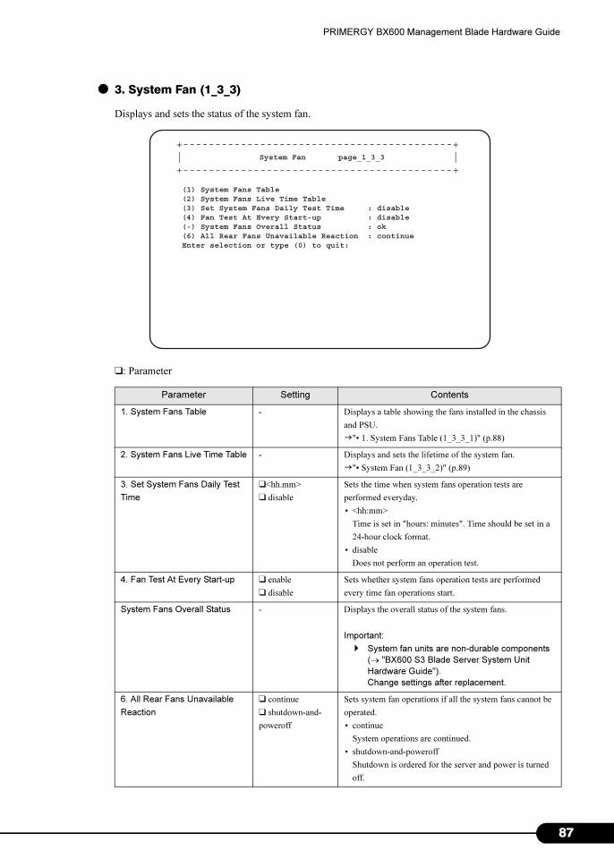
PRIMERGY BX600 Management Blade Hardware Guide
● 3. System Fan (1_3_3)
Displays and sets the status of the system fan.
❑: Parameter
Parameter Setting Contents
1. System Fans Table - Displays a table showing the fans installed in the chassis
and PSU.
�"• 1. System Fans Table (1_3_3_1)" (p.88)
2. System Fans Live Time Table - Displays and sets the lifetime of the system fan.
�"• System Fan (1_3_3_2)" (p.89)
3. Set System Fans Daily Test
Time
❑<hh.mm>
❑ disable
Sets the time when system fans operation tests are
performed everyday.
• <hh:mm>
Time is set in "hours: minutes". Time should be set in a
24-hour clock format.
• disable
Does not perform an operation test.
4. Fan Test At Every Start-up ❑ enable
❑ disable
Sets whether system fans operation tests are performed
every time fan operations start.
System Fans Overall Status - Displays the overall status of the system fans.
Important:
� System fan units are non-durable components
(→ "BX600 S3 Blade Server System Unit
Hardware Guide").
Change settings after replacement.
6. All Rear Fans Unavailable
Reaction
❑ continue
❑ shutdown-and-
poweroff
Sets system fan operations if all the system fans cannot be
operated.
• continue
System operations are continued.
• shutdown-and-poweroff
Shutdown is ordered for the server and power is turned
off.
+------------------------------------------+| |+------------------------------------------+
System Fan page_1_3_3
(1) System Fans Table(2) System Fans Live Time Table(3) Set System Fans Daily Test Time : disable(4) Fan Test At Every Start-up : disable(-) System Fans Overall Status : ok(6) All Rear Fans Unavailable Reaction : continueEnter selection or type (0) to quit:
87
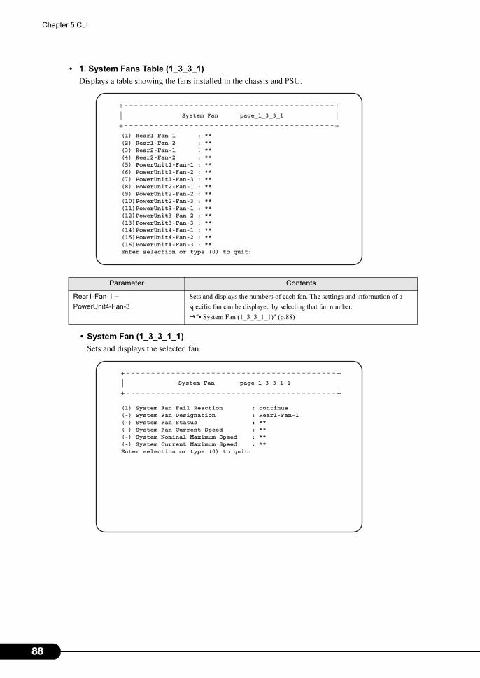
8
Chapter 5 CLI
• 1. System Fans Table (1_3_3_1)
Displays a table showing the fans installed in the chassis and PSU.
• System Fan (1_3_3_1_1)
Sets and displays the selected fan.
Parameter Contents
Rear1-Fan-1 –
PowerUnit4-Fan-3
Sets and displays the numbers of each fan. The settings and information of a
specific fan can be displayed by selecting that fan number.
�"• System Fan (1_3_3_1_1)" (p.88)
+------------------------------------------+| |+------------------------------------------+
System Fan page_1_3_3_1
(1) Rear1-Fan-1 : **(2) Rear1-Fan-2 : **(3) Rear2-Fan-1 : **(4) Rear2-Fan-2 : **(5) PowerUnit1-Fan-1 : **(6) PowerUnit1-Fan-2 : **(7) PowerUnit1-Fan-3 : **(8) PowerUnit2-Fan-1 : **(9) PowerUnit2-Fan-2 : **(10)PowerUnit2-Fan-3 : **(11)PowerUnit3-Fan-1 : **(12)PowerUnit3-Fan-2 : **(13)PowerUnit3-Fan-3 : **(14)PowerUnit4-Fan-1 : **(15)PowerUnit4-Fan-2 : **(16)PowerUnit4-Fan-3 : **Enter selection or type (0) to quit:
+------------------------------------------+| |+------------------------------------------+
System Fan page_1_3_3_1_1
(1) System Fan Fail Reaction : continue(-) System Fan Designation : Rear1-Fan-1(-) System Fan Status : **(-) System Fan Current Speed : **(-) System Nominal Maximum Speed : **(-) System Current Maximum Speed : **Enter selection or type (0) to quit:
8
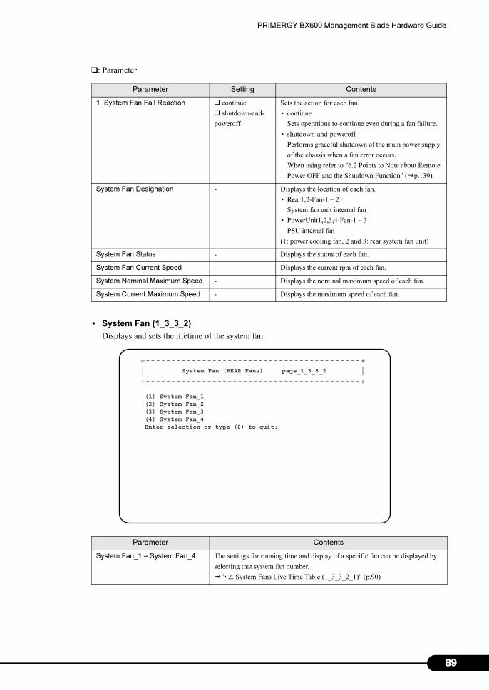
PRIMERGY BX600 Management Blade Hardware Guide
❑: Parameter
• System Fan (1_3_3_2)
Displays and sets the lifetime of the system fan.
Parameter Setting Contents
1. System Fan Fail Reaction ❑ continue
❑ shutdown-and-
poweroff
Sets the action for each fan.
• continue
Sets operations to continue even during a fan failure.
• shutdown-and-poweroff
Performs graceful shutdown of the main power supply
of the chassis when a fan error occurs.
When using refer to "6.2 Points to Note about Remote
Power OFF and the Shutdown Function" (�p.139).
System Fan Designation - Displays the location of each fan.
• Rear1,2-Fan-1 – 2
System fan unit internal fan
• PowerUnit1,2,3,4-Fan-1 – 3
PSU internal fan
(1: power cooling fan, 2 and 3: rear system fan unit)
System Fan Status - Displays the status of each fan.
System Fan Current Speed - Displays the current rpm of each fan.
System Nominal Maximum Speed - Displays the nominal maximum speed of each fan.
System Current Maximum Speed - Displays the maximum speed of each fan.
Parameter Contents
System Fan_1 – System Fan_4 The settings for running time and display of a specific fan can be displayed by
selecting that system fan number.
�"• 2. System Fans Live Time Table (1_3_3_2_1)" (p.90)
+------------------------------------------+| |+------------------------------------------+
System Fan (REAR Fans) page_1_3_3_2
(1) System Fan_1(2) System Fan_2(3) System Fan_3(4) System Fan_4Enter selection or type (0) to quit:
89
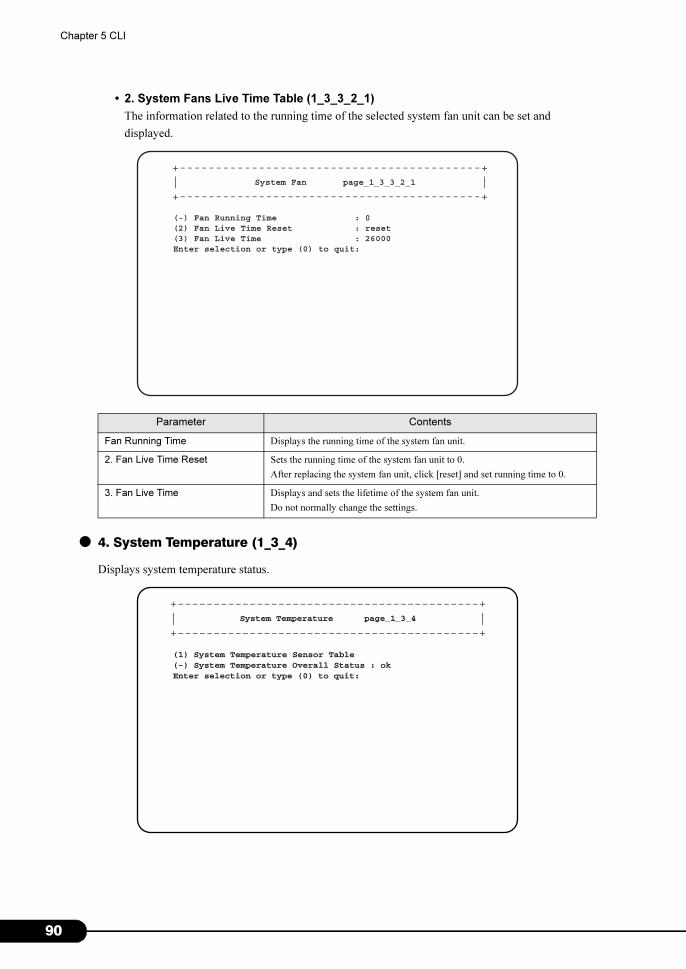
9
Chapter 5 CLI
• 2. System Fans Live Time Table (1_3_3_2_1)
The information related to the running time of the selected system fan unit can be set and
displayed.
● 4. System Temperature (1_3_4)
Displays system temperature status.
Parameter Contents
Fan Running Time Displays the running time of the system fan unit.
2. Fan Live Time Reset Sets the running time of the system fan unit to 0.
After replacing the system fan unit, click [reset] and set running time to 0.
3. Fan Live Time Displays and sets the lifetime of the system fan unit.
Do not normally change the settings.
+------------------------------------------+| |+------------------------------------------+
System Fan page_1_3_3_2_1
(-) Fan Running Time : 0(2) Fan Live Time Reset : reset(3) Fan Live Time : 26000Enter selection or type (0) to quit:
+------------------------------------------+| |+------------------------------------------+
System Temperature page_1_3_4
(1) System Temperature Sensor Table(-) System Temperature Overall Status : okEnter selection or type (0) to quit:
0
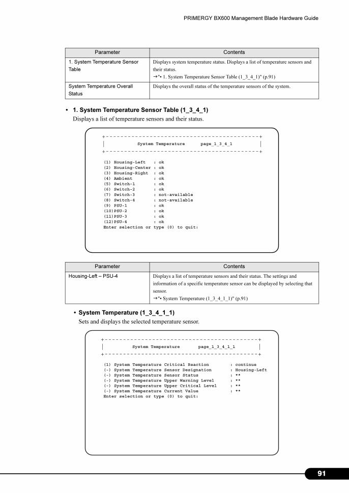
PRIMERGY BX600 Management Blade Hardware Guide
• 1. System Temperature Sensor Table (1_3_4_1)
Displays a list of temperature sensors and their status.
• System Temperature (1_3_4_1_1)
Sets and displays the selected temperature sensor.
Parameter Contents
1. System Temperature Sensor
Table
Displays system temperature status. Displays a list of temperature sensors and
their status.
�"• 1. System Temperature Sensor Table (1_3_4_1)" (p.91)
System Temperature Overall
Status
Displays the overall status of the temperature sensors of the system.
Parameter Contents
Housing-Left – PSU-4 Displays a list of temperature sensors and their status. The settings and
information of a specific temperature sensor can be displayed by selecting that
sensor.
�"• System Temperature (1_3_4_1_1)" (p.91)
+------------------------------------------+| |+------------------------------------------+
System Temperature page_1_3_4_1
(1) Housing-Left : ok(2) Housing-Center : ok(3) Housing-Right : ok(4) Ambient : ok(5) Switch-1 : ok(6) Switch-2 : ok(7) Switch-3 : not-available(8) Switch-4 : not-available(9) PSU-1 : ok(10)PSU-2 : ok(11)PSU-3 : ok(12)PSU-4 : okEnter selection or type (0) to quit:
+------------------------------------------+| |+------------------------------------------+
System Temperature page_1_3_4_1_1
(1) System Temperature Critical Reaction : continue(-) System Temperature Sensor Designation : Housing-Left(-) System Temperature Sensor Status : **(-) System Temperature Upper Warning Level : **(-) System Temperature Upper Critical Level : **(-) System Temperature Current Value : **Enter selection or type (0) to quit:
91
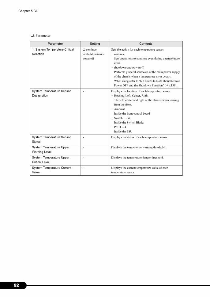
9
Chapter 5 CLI
❑: Parameter
Parameter Setting Contents
1. System Temperature Critical
Reaction
❑ continue
❑ shutdown-and-
poweroff
Sets the action for each temperature sensor.
• continue
Sets operations to continue even during a temperature
error.
• shutdown-and-poweroff
Performs graceful shutdown of the main power supply
of the chassis when a temperature error occurs.
When using refer to "6.2 Points to Note about Remote
Power OFF and the Shutdown Function" (�p.139).
System Temperature Sensor
Designation
- Displays the location of each temperature sensor.
• Housing-Left, Center, Right
The left, center and right of the chassis when looking
from the front.
• Ambient
Inside the front control board
• Switch 1 – 4:
Inside the Switch Blade:
• PSU1 – 4
Inside the PSU
System Temperature Sensor
Status
- Displays the status of each temperature sensor.
System Temperature Upper
Warning Level
- Displays the temperature warning threshold.
System Temperature Upper
Critical Level
- Displays the temperature danger threshold.
System Temperature Current
Value
- Displays the current temperature value of each
temperature sensor.
2
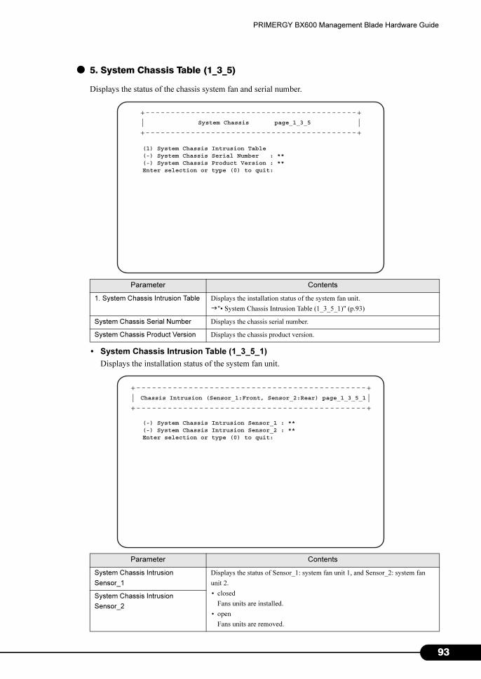
PRIMERGY BX600 Management Blade Hardware Guide
● 5. System Chassis Table (1_3_5)
Displays the status of the chassis system fan and serial number.
• System Chassis Intrusion Table (1_3_5_1)
Displays the installation status of the system fan unit.
Parameter Contents
1. System Chassis Intrusion Table Displays the installation status of the system fan unit.
�"• System Chassis Intrusion Table (1_3_5_1)" (p.93)
System Chassis Serial Number Displays the chassis serial number.
System Chassis Product Version Displays the chassis product version.
Parameter Contents
System Chassis Intrusion
Sensor_1
Displays the status of Sensor_1: system fan unit 1, and Sensor_2: system fan
unit 2.
• closed
Fans units are installed.
• open
Fans units are removed.
System Chassis Intrusion
Sensor_2
+------------------------------------------+| |+------------------------------------------+
System Chassis page_1_3_5
(1) System Chassis Intrusion Table(-) System Chassis Serial Number : **(-) System Chassis Product Version : **Enter selection or type (0) to quit:
+--------------------------------------------+| |+--------------------------------------------+
Chassis Intrusion (Sensor_1:Front, Sensor_2:Rear) page_1_3_5_1
(-) System Chassis Intrusion Sensor_1 : **(-) System Chassis Intrusion Sensor_2 : **Enter selection or type (0) to quit:
93
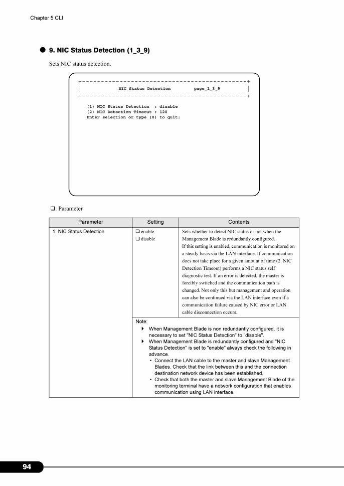
9
Chapter 5 CLI
● 9. NIC Status Detection (1_3_9)
Sets NIC status detection.
❑: Parameter
Parameter Setting Contents
1. NIC Status Detection ❑ enable
❑ disable
Sets whether to detect NIC status or not when the
Management Blade is redundantly configured.
If this setting is enabled, communication is monitored on
a steady basis via the LAN interface. If communication
does not take place for a given amount of time (2. NIC
Detection Timeout) performs a NIC status self
diagnostic test. If an error is detected, the master is
forcibly switched and the communication path is
changed. Not only this but management and operation
can also be continued via the LAN interface even if a
communication failure caused by NIC error or LAN
cable disconnection occurs.
Note:
� When Management Blade is non redundantly configured, it is
necessary to set "NIC Status Detection" to "disable".
� When Management Blade is redundantly configured and "NIC
Status Detection" is set to "enable" always check the following in
advance.
• Connect the LAN cable to the master and slave Management
Blades. Check that the link between this and the connection
destination network device has been established.
• Check that both the master and slave Management Blade of the
monitoring terminal have a network configuration that enables
communication using LAN interface.
+--------------------------------------------+| |+--------------------------------------------+
NIC Status Detection page_1_3_9
(1) NIC Status Detection : disable(2) NIC Detection Timeout : 120Enter selection or type (0) to quit:
4
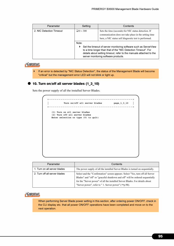
PRIMERGY BX600 Management Blade Hardware Guide
● 10. Turn on/off all server blades (1_3_10)
Sets the power supply of all the installed Server Blades.
2. NIC Detection Timeout ❑ 0 – 300 Sets the time (seconds) for NIC status detection. If
communication does not take place in the setting time
here, a NIC status self diagnostic test is performed.
Note:
� Set the timeout of server monitoring software such as ServerView
to a time longer than that of the "NIC Detection Timeout". For
details about setting timeout, refer to the manuals attached to the
server monitoring software products.
� If an error is detected by "NIC Status Detection", the status of the Management Blade will become
"critical" but the management error LED will not blink or light up.
Parameter Contents
1. Turn on all server blades The power supply of all the installed Server Blades is turned on sequentially.
2. Turn off all server blades Select and the "Confirmation" screen appears. Select "Yes, turn off all Server
Blades" and "off" or "graceful shutdown and off" will be ordered sequentially
for the "Server power" of all the installed Server Blades. For details about
"Server power", refer to " 1. Server power" (�p.98).
When performing Server Blade power setting in this section, after ordering power ON/OFF, check in
the CLI display etc. that all power ON/OFF operations have been completed and move on to the
next operation.
Parameter Setting Contents
+--------------------------------------------+| |+--------------------------------------------+
Turn on/off all server blades page_1_3_10
(1) Turn on all server blades(2) Turn off all server bladesEnter selection or type (0) to quit:
95
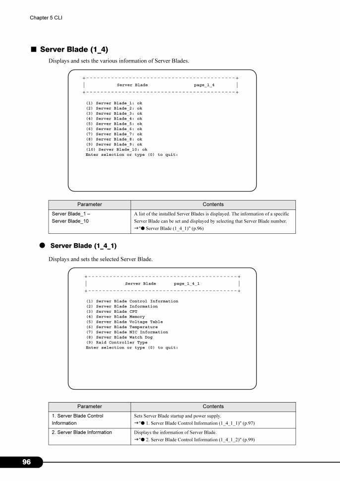
9
Chapter 5 CLI
■ Server Blade (1_4)
Displays and sets the various information of Server Blades.
● Server Blade (1_4_1)
Displays and sets the selected Server Blade.
Parameter Contents
Server Blade_1 –
Server Blade_10
A list of the installed Server Blades is displayed. The information of a specific
Server Blade can be set and displayed by selecting that Server Blade number.
�"● Server Blade (1_4_1)" (p.96)
Parameter Contents
1. Server Blade Control
Information
Sets Server Blade startup and power supply.
�"● 1. Server Blade Control Information (1_4_1_1)" (p.97)
2. Server Blade Information Displays the information of Server Blade.
�"● 2. Server Blade Control Information (1_4_1_2)" (p.99)
Server Blade page_1_4
(1) Server Blade_1: ok(2) Server Blade_2: ok(3) Server Blade_3: ok(4) Server Blade_4: ok(5) Server Blade_5: ok(6) Server Blade_6: ok(7) Server Blade_7: ok(8) Server Blade_8: ok(9) Server Blade_9: ok(10) Server Blade_10: okEnter selection or type (0) to quit:
+------------------------------------------+| |+------------------------------------------+
Server Blade page_1_4_1
(1) Server Blade Control Information(2) Server Blade Information(3) Server Blade CPU(4) Server Blade Memory(5) Server Blade Voltage Table(6) Server Blade Temperature(7) Server Blade NIC Information(8) Server Blade Watch Dog(9) Raid Controller TypeEnter selection or type (0) to quit:
+------------------------------------------+| |+------------------------------------------+
6
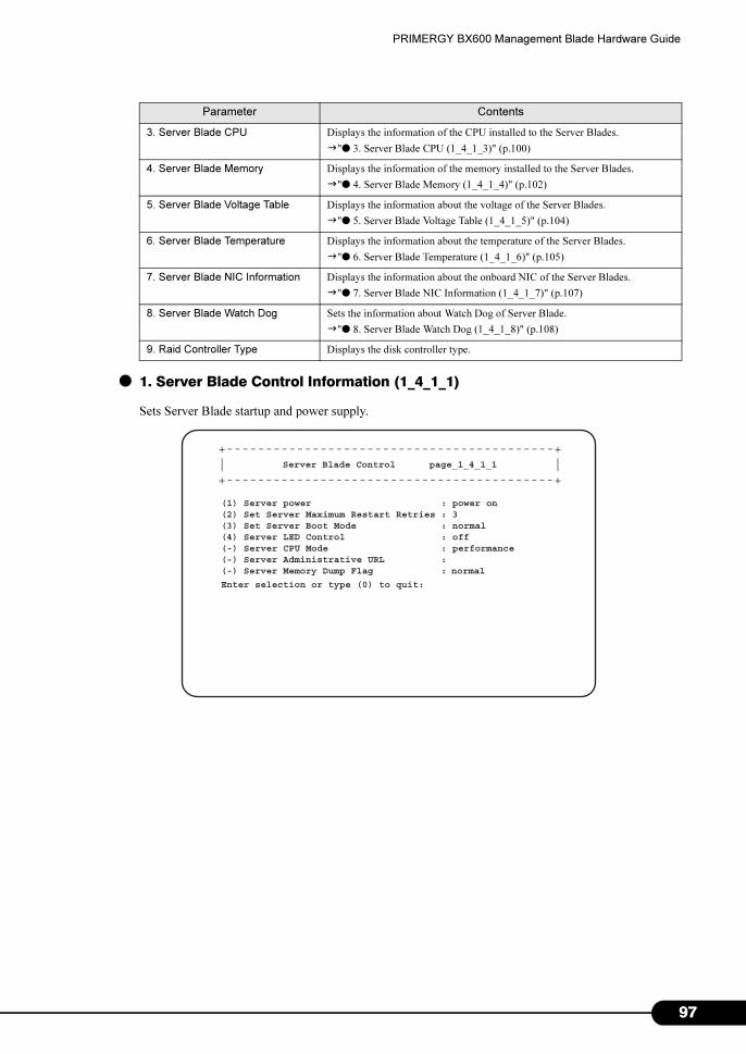
PRIMERGY BX600 Management Blade Hardware Guide
● 1. Server Blade Control Information (1_4_1_1)
Sets Server Blade startup and power supply.
3. Server Blade CPU Displays the information of the CPU installed to the Server Blades.
�"● 3. Server Blade CPU (1_4_1_3)" (p.100)
4. Server Blade Memory Displays the information of the memory installed to the Server Blades.
�"● 4. Server Blade Memory (1_4_1_4)" (p.102)
5. Server Blade Voltage Table Displays the information about the voltage of the Server Blades.
�"● 5. Server Blade Voltage Table (1_4_1_5)" (p.104)
6. Server Blade Temperature Displays the information about the temperature of the Server Blades.
�"● 6. Server Blade Temperature (1_4_1_6)" (p.105)
7. Server Blade NIC Information Displays the information about the onboard NIC of the Server Blades.
�"● 7. Server Blade NIC Information (1_4_1_7)" (p.107)
8. Server Blade Watch Dog Sets the information about Watch Dog of Server Blade.
�"● 8. Server Blade Watch Dog (1_4_1_8)" (p.108)
9. Raid Controller Type Displays the disk controller type.
Parameter Contents
Server Blade Control page_1_4_1_1
(1) Server power : power on(2) Set Server Maximum Restart Retries : 3(3) Set Server Boot Mode : normal(4) Server LED Control : off(-) Server CPU Mode : performance(-) Server Administrative URL :(-) Server Memory Dump Flag : normal
Enter selection or type (0) to quit:
+------------------------------------------+| |+------------------------------------------+
97
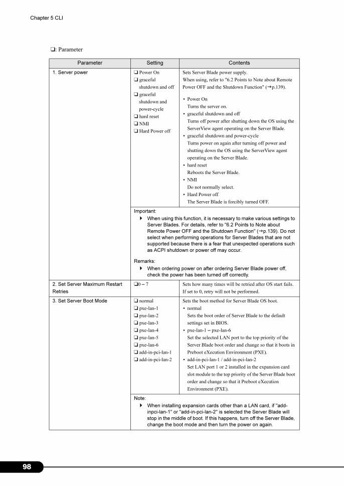
9
Chapter 5 CLI
❑: Parameter
Parameter Setting Contents
1. Server power ❑ Power On
❑ graceful
shutdown and off
❑ graceful
shutdown and
power-cycle
❑ hard reset
❑ NMI
❑ Hard Power off
Sets Server Blade power supply.
When using, refer to "6.2 Points to Note about Remote
Power OFF and the Shutdown Function" (�p.139).
• Power On
Turns the server on.
• graceful shutdown and off
Turns off power after shutting down the OS using the
ServerView agent operating on the Server Blade.
• graceful shutdown and power-cycle
Turns power on again after turning off power and
shutting down the OS using the ServerView agent
operating on the Server Blade.
• hard reset
Reboots the Server Blade.
• NMI
Do not normally select.
• Hard Power off
The Server Blade is forcibly turned OFF.
Important:
� When using this function, it is necessary to make various settings to
Server Blades. For details, refer to "6.2 Points to Note about
Remote Power OFF and the Shutdown Function" (�p.139). Do not
select when performing operations for Server Blades that are not
supported because there is a fear that unexpected operations such
as ACPI shutdown or power off may occur.
Remarks:
� When ordering power on after ordering Server Blade power off,
check the power has been turned off correctly.
2. Set Server Maximum Restart
Retries
❑0 – 7 Sets how many times will be retried after OS start fails.
If set to 0, retry will not be performed.
3. Set Server Boot Mode ❑ normal
❑ pxe-lan-1
❑ pxe-lan-2
❑ pxe-lan-3
❑ pxe-lan-4
❑ pxe-lan-5
❑ pxe-lan-6
❑ add-in-pci-lan-1
❑ add-in-pci-lan-2
Sets the boot method for Server Blade OS boot.
• normal
Sets the boot order of Server Blade to the default
settings set in BIOS.
• pxe-lan-1 – pxe-lan-6
Set the selected LAN port to the top priority of the
Server Blade boot order and change so that it boots in
Preboot eXecution Environment (PXE).
• add-in-pci-lan-1 / add-in-pci-lan-2
Set LAN port 1 or 2 installed in the expansion card
slot module to the top priority of the Server Blade boot
order and change so that it Preboot eXecution
Environment (PXE).
Note:
� When installing expansion cards other than a LAN card, if "add-
inpci-lan-1" or "add-in-pci-lan-2" is selected the Server Blade will
stop in the middle of boot. If this happens, turn off the Server Blade,
change the boot mode and then turn the power on again.
8
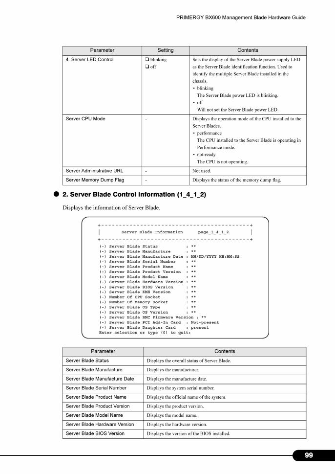
PRIMERGY BX600 Management Blade Hardware Guide
● 2. Server Blade Control Information (1_4_1_2)
Displays the information of Server Blade.
4. Server LED Control ❑ blinking
❑ off
Sets the display of the Server Blade power supply LED
as the Server Blade identification function. Used to
identify the multiple Server Blade installed in the
chassis.
• blinking
The Server Blade power LED is blinking.
• off
Will not set the Server Blade power LED.
Server CPU Mode - Displays the operation mode of the CPU installed to the
Server Blades.
• performance
The CPU installed to the Server Blade is operating in
Performance mode.
• not-ready
The CPU is not operating.
Server Administrative URL - Not used.
Server Memory Dump Flag - Displays the status of the memory dump flag.
Parameter Contents
Server Blade Status Displays the overall status of Server Blade.
Server Blade Manufacture Displays the manufacturer.
Server Blade Manufacture Date Displays the manufacture date.
Server Blade Serial Number Displays the system serial number.
Server Blade Product Name Displays the official name of the system.
Server Blade Product Version Displays the product version.
Server Blade Model Name Displays the model name.
Server Blade Hardware Version Displays the hardware version.
Server Blade BIOS Version Displays the version of the BIOS installed.
Parameter Setting Contents
Server Blade Information page_1_4_1_2
(-) Server Blade Status : **(-) Server Blade Manufacture : **(-) Server Blade Manufacture Date : MM/DD/YYYY HH:MM:SS(-) Server Blade Serial Number : **(-) Server Blade Product Name : **(-) Server Blade Product Version : **(-) Server Blade Model Name : **(-) Server Blade Hardware Version : **
(-) Server Blade KME Version : **(-) Number Of CPU Socket : **(-) Number Of Memory Socket : **(-) Server Blade OS Type : **(-) Server Blade OS Version : **(-) Server Blade BMC Firmware Version : **(-) Server Blade PCI Add-In Card : Not-present(-) Server Blade Daughter Card : presentEnter selection or type (0) to quit:
+------------------------------------------+| |+------------------------------------------+
(-) Server Blade BIOS Version : **
99
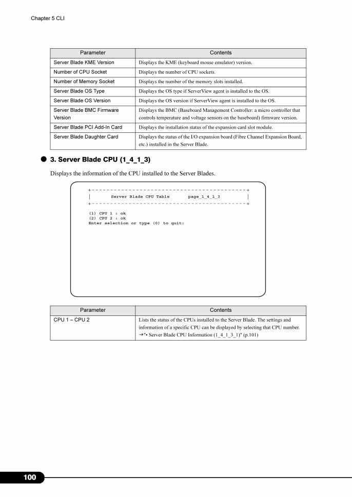
1
Chapter 5 CLI
● 3. Server Blade CPU (1_4_1_3)
Displays the information of the CPU installed to the Server Blades.
Server Blade KME Version Displays the KME (keyboard mouse emulator) version.
Number of CPU Socket Displays the number of CPU sockets.
Number of Memory Socket Displays the number of the memory slots installed.
Server Blade OS Type Displays the OS type if ServerView agent is installed to the OS.
Server Blade OS Version Displays the OS version if ServerView agent is installed to the OS.
Server Blade BMC Firmware
Version
Displays the BMC (Baseboard Management Controller: a micro controller that
controls temperature and voltage sensors on the baseboard) firmware version.
Server Blade PCI Add-In Card Displays the installation status of the expansion card slot module.
Server Blade Daughter Card Displays the status of the I/O expansion board (Fibre Channel Expansion Board,
etc.) installed in the Server Blade.
Parameter Contents
CPU 1 – CPU 2 Lists the status of the CPUs installed to the Server Blade. The settings and
information of a specific CPU can be displayed by selecting that CPU number.
�"• Server Blade CPU Information (1_4_1_3_1)" (p.101)
Parameter Contents
Server Blade CPU Table page_1_4_1_3
(1) CPU 1 : ok(2) CPU 2 : okEnter selection or type (0) to quit:
+------------------------------------------+| |+------------------------------------------+
00
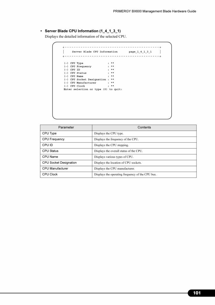
PRIMERGY BX600 Management Blade Hardware Guide
• Server Blade CPU Information (1_4_1_3_1)
Displays the detailed information of the selected CPU.
Parameter Contents
CPU Type Displays the CPU type.
CPU Frequency Displays the frequency of the CPU.
CPU ID Displays the CPU stepping.
CPU Status Displays the overall status of the CPU.
CPU Name Displays various types of CPU.
CPU Socket Designation Displays the location of CPU sockets.
CPU Manufacturer Displays the CPU manufacturer.
CPU Clock Displays the operating frequency of the CPU bus.
Server Blade CPU Information page_1_4_1_3_1
(-) CPU Type : **(-) CPU Frequency : **(-) CPU ID : **(-) CPU Status : **(-) CPU Name : **(-) CPU Socket Designation : **(-) CPU Manufacturer : **(-) CPU Clock : **Enter selection or type (0) to quit:
+------------------------------------------+| |+------------------------------------------+
101
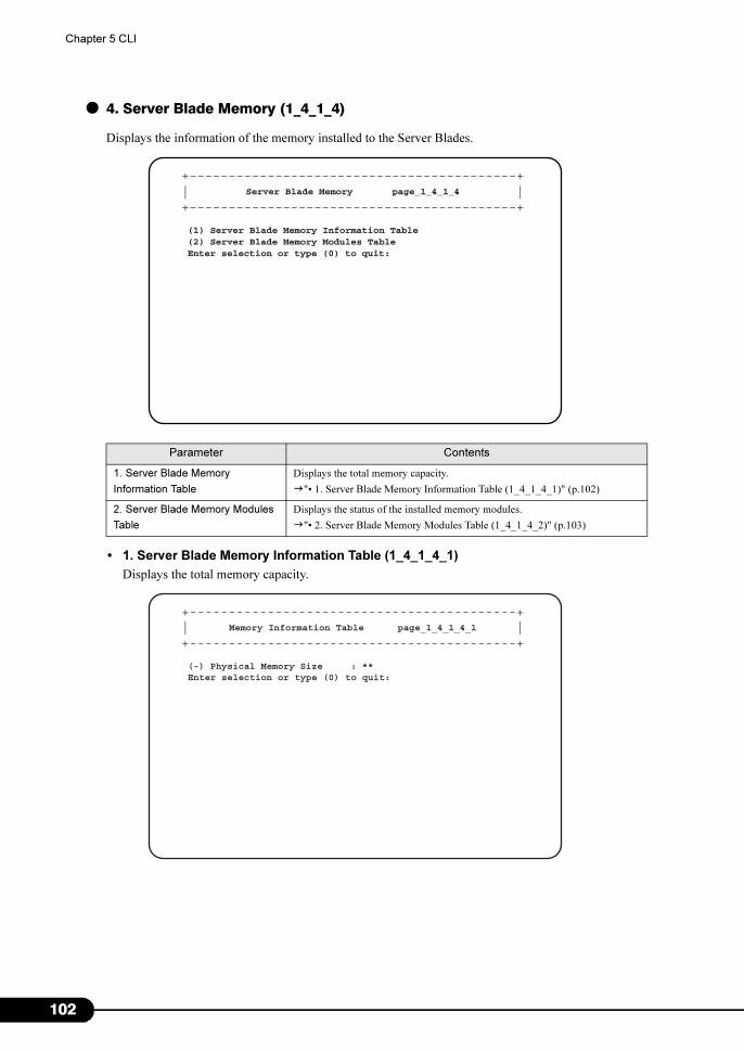
1
Chapter 5 CLI
● 4. Server Blade Memory (1_4_1_4)
Displays the information of the memory installed to the Server Blades.
• 1. Server Blade Memory Information Table (1_4_1_4_1)
Displays the total memory capacity.
Parameter Contents
1. Server Blade Memory
Information Table
Displays the total memory capacity.
�"• 1. Server Blade Memory Information Table (1_4_1_4_1)" (p.102)
2. Server Blade Memory Modules
Table
Displays the status of the installed memory modules.
�"• 2. Server Blade Memory Modules Table (1_4_1_4_2)" (p.103)
Server Blade Memory page_1_4_1_4
(1) Server Blade Memory Information Table(2) Server Blade Memory Modules TableEnter selection or type (0) to quit:
+------------------------------------------+| |+------------------------------------------+
Memory Information Table page_1_4_1_4_1
(-) Physical Memory Size : **Enter selection or type (0) to quit:
+------------------------------------------+| |+------------------------------------------+
02
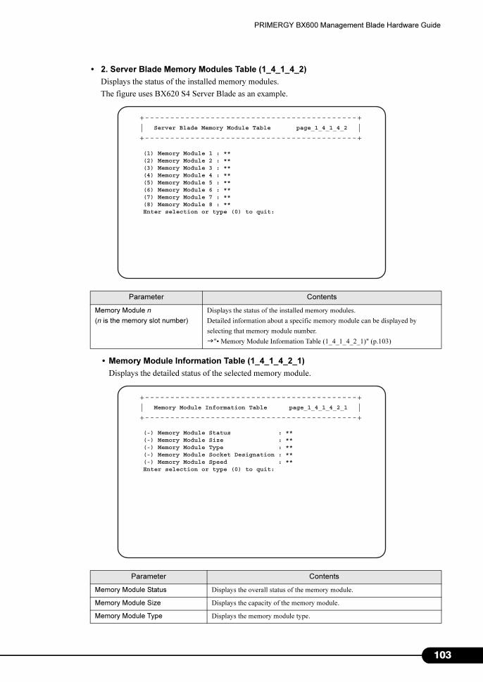
PRIMERGY BX600 Management Blade Hardware Guide
• 2. Server Blade Memory Modules Table (1_4_1_4_2)
Displays the status of the installed memory modules.
The figure uses BX620 S4 Server Blade as an example.
• Memory Module Information Table (1_4_1_4_2_1)
Displays the detailed status of the selected memory module.
Parameter Contents
Memory Module n
(n is the memory slot number)
Displays the status of the installed memory modules.
Detailed information about a specific memory module can be displayed by
selecting that memory module number.
�"• Memory Module Information Table (1_4_1_4_2_1)" (p.103)
Parameter Contents
Memory Module Status Displays the overall status of the memory module.
Memory Module Size Displays the capacity of the memory module.
Memory Module Type Displays the memory module type.
Server Blade Memory Module Table page_1_4_1_4_2
(1) Memory Module 1 : **(2) Memory Module 2 : **(3) Memory Module 3 : **(4) Memory Module 4 : **(5) Memory Module 5 : **(6) Memory Module 6 : **(7) Memory Module 7 : **(8) Memory Module 8 : **Enter selection or type (0) to quit:
+------------------------------------------+| |+------------------------------------------+
Memory Module Information Table page_1_4_1_4_2_1
(-) Memory Module Status : **(-) Memory Module Size : **(-) Memory Module Type : **(-) Memory Module Socket Designation : **(-) Memory Module Speed : **Enter selection or type (0) to quit:
+------------------------------------------+| |+------------------------------------------+
103
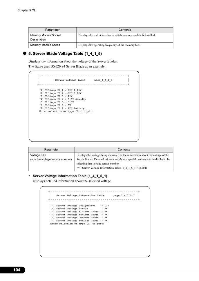
1
Chapter 5 CLI
● 5. Server Blade Voltage Table (1_4_1_5)
Displays the information about the voltage of the Server Blades.
The figure uses BX620 S4 Server Blade as an example.
• Server Voltage Information Table (1_4_1_5_1)
Displays detailed information about the selected voltage.
Memory Module Socket
Designation
Displays the socket location to which memory module is installed.
Memory Module Speed Displays the operating frequency of the memory bus.
Parameter Contents
Voltage ID n
(n is the voltage sensor number)
Displays the voltage being measured as the information about the voltage of the
Server Blades. Detailed information about a specific voltage can be displayed by
selecting that voltage sensor number.
�"• Server Voltage Information Table (1_4_1_5_1)" (p.104)
Parameter Contents
Server Voltage Table page_1_4_1_5
(1) Voltage ID 1 : CPU 2 12V(2) Voltage ID 2 : CPU 1 12V(3) Voltage ID 3 : 12V(4) Voltage ID 4 : 3.3V Standby(5) Voltage ID 5 : 3.3V(6) Voltage ID 6 : 5V(7) Voltage ID 7 : RTC BatteryEnter selection or type (0) to quit:
+------------------------------------------+| |+------------------------------------------+
Server Voltage Information Table page_1_4_1_5_1
(-) Server Voltage Designation : 12V(-) Server Voltage Status : **(-) Server Voltage Minimum Value : **(-) Server Voltage Maximum Value : **(-) Server Voltage Current Value : **(-) Server Voltage Nominal Value : **Enter selection or type (0) to quit:
+------------------------------------------+| |+------------------------------------------+
04
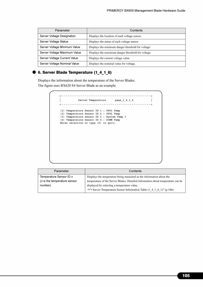
PRIMERGY BX600 Management Blade Hardware Guide
● 6. Server Blade Temperature (1_4_1_6)
Displays the information about the temperature of the Server Blades.
The figure uses BX620 S4 Server Blade as an example.
Parameter Contents
Server Voltage Designation Displays the location of each voltage sensor.
Server Voltage Status Displays the status of each voltage sensor.
Server Voltage Minimum Value Displays the minimum danger threshold for voltage.
Server Voltage Maximum Value Displays the maximum danger threshold for voltage.
Server Voltage Current Value Displays the current voltage value.
Server Voltage Nominal Value Displays the nominal value for voltage.
Parameter Contents
Temperature Sensor ID n
(n is the temperature sensor
number)
Displays the temperature being measured as the information about the
temperature of the Server Blades. Detailed information about temperature can be
displayed by selecting a temperature value.
�"• Server Temperature Sensor Information Table (1_4_1_6_1)" (p.106)
Server Temperature page_1_4_1_6
(1) Temperature Sensor ID 1 : CPU1 Temp(2) Temperature Sensor ID 2 : CPU2 Temp(3) Temperature Sensor ID 3 : System Temp 3(4) Temperature Sensor ID 4 : DIMM TempEnter selection or type (0) to quit:
+------------------------------------------+| |+------------------------------------------+
105
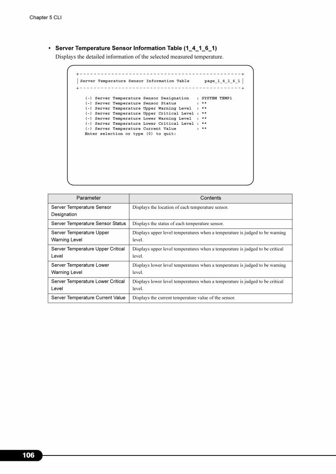
1
Chapter 5 CLI
• Server Temperature Sensor Information Table (1_4_1_6_1)
Displays the detailed information of the selected measured temperature.
Parameter Contents
Server Temperature Sensor
Designation
Displays the location of each temperature sensor.
Server Temperature Sensor Status Displays the status of each temperature sensor.
Server Temperature Upper
Warning Level
Displays upper level temperatures when a temperature is judged to be warning
level.
Server Temperature Upper Critical
Level
Displays upper level temperatures when a temperature is judged to be critical
level.
Server Temperature Lower
Warning Level
Displays lower level temperatures when a temperature is judged to be warning
level.
Server Temperature Lower Critical
Level
Displays lower level temperatures when a temperature is judged to be critical
level.
Server Temperature Current Value Displays the current temperature value of the sensor.
Server Temperature Sensor Information Table page_1_4_1_6_1
(-) Server Temperature Sensor Designation : SYSTEM TEMP1(-) Server Temperature Sensor Status : **(-) Server Temperature Upper Warning Level : **(-) Server Temperature Upper Critical Level : **(-) Server Temperature Lower Warning Level : **(-) Server Temperature Lower Critical Level : **(-) Server Temperature Current Value : **Enter selection or type (0) to quit:
+----------------------------------------------+| |+----------------------------------------------+
06
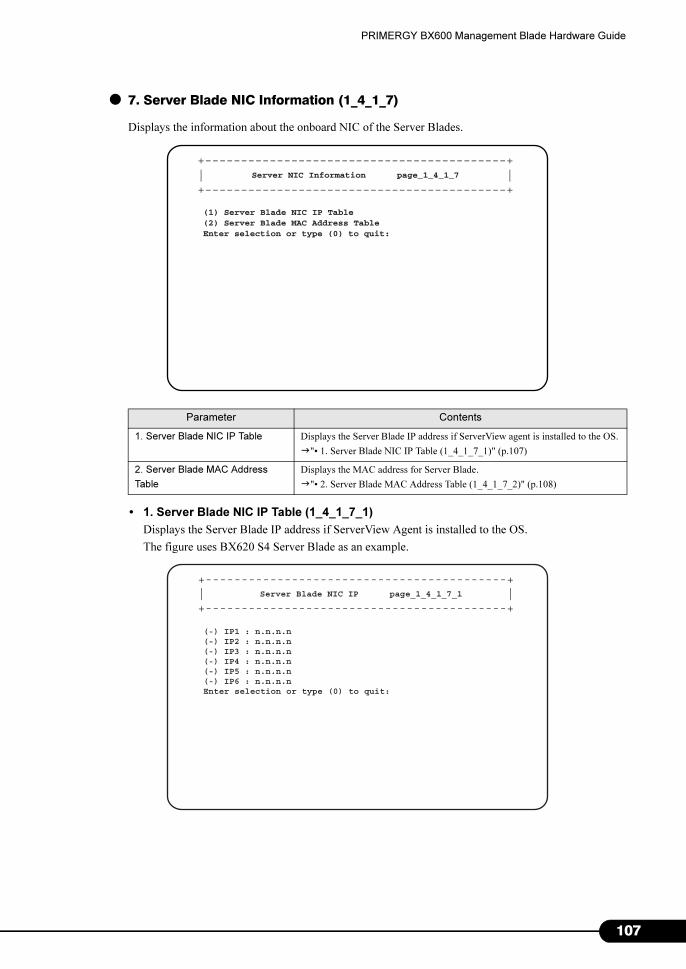
PRIMERGY BX600 Management Blade Hardware Guide
● 7. Server Blade NIC Information (1_4_1_7)
Displays the information about the onboard NIC of the Server Blades.
• 1. Server Blade NIC IP Table (1_4_1_7_1)
Displays the Server Blade IP address if ServerView Agent is installed to the OS.
The figure uses BX620 S4 Server Blade as an example.
Parameter Contents
1. Server Blade NIC IP Table Displays the Server Blade IP address if ServerView agent is installed to the OS.
�"• 1. Server Blade NIC IP Table (1_4_1_7_1)" (p.107)
2. Server Blade MAC Address
Table
Displays the MAC address for Server Blade.
�"• 2. Server Blade MAC Address Table (1_4_1_7_2)" (p.108)
Server NIC Information page_1_4_1_7
(1) Server Blade NIC IP Table(2) Server Blade MAC Address TableEnter selection or type (0) to quit:
+------------------------------------------+| |+------------------------------------------+
Server Blade NIC IP page_1_4_1_7_1
(-) IP1 : n.n.n.n(-) IP2 : n.n.n.n(-) IP3 : n.n.n.n(-) IP4 : n.n.n.n(-) IP5 : n.n.n.n(-) IP6 : n.n.n.nEnter selection or type (0) to quit:
+------------------------------------------+| |+------------------------------------------+
107
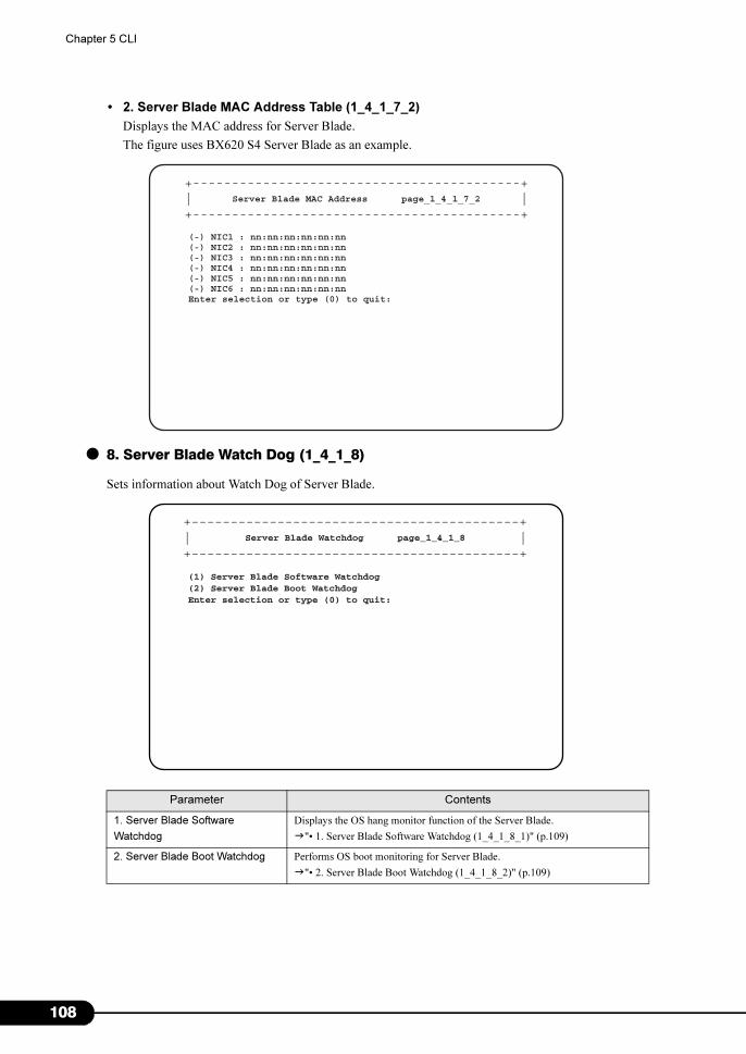
1
Chapter 5 CLI
• 2. Server Blade MAC Address Table (1_4_1_7_2)
Displays the MAC address for Server Blade.
The figure uses BX620 S4 Server Blade as an example.
● 8. Server Blade Watch Dog (1_4_1_8)
Sets information about Watch Dog of Server Blade.
Parameter Contents
1. Server Blade Software
Watchdog
Displays the OS hang monitor function of the Server Blade.
�"• 1. Server Blade Software Watchdog (1_4_1_8_1)" (p.109)
2. Server Blade Boot Watchdog Performs OS boot monitoring for Server Blade.
�"• 2. Server Blade Boot Watchdog (1_4_1_8_2)" (p.109)
Server Blade MAC Address page_1_4_1_7_2
(-) NIC1 : nn:nn:nn:nn:nn:nn(-) NIC2 : nn:nn:nn:nn:nn:nn(-) NIC3 : nn:nn:nn:nn:nn:nn(-) NIC4 : nn:nn:nn:nn:nn:nn(-) NIC5 : nn:nn:nn:nn:nn:nn(-) NIC6 : nn:nn:nn:nn:nn:nnEnter selection or type (0) to quit:
+------------------------------------------+| |+------------------------------------------+
+------------------------------------------+| |+------------------------------------------+
Server Blade Watchdog page_1_4_1_8
(1) Server Blade Software Watchdog(2) Server Blade Boot WatchdogEnter selection or type (0) to quit:
08
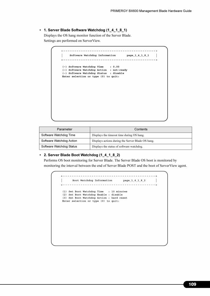
PRIMERGY BX600 Management Blade Hardware Guide
• 1. Server Blade Software Watchdog (1_4_1_8_1)
Displays the OS hang monitor function of the Server Blade.
Settings are performed on ServerView.
• 2. Server Blade Boot Watchdog (1_4_1_8_2)
Performs OS boot monitoring for Server Blade. The Server Blade OS boot is monitored by
monitoring the interval between the end of Server Blade POST and the boot of ServerView agent.
Parameter Contents
Software Watchdog Time Displays the timeout time during OS hang.
Software Watchdog Action Displays actions during the Server Blade OS hang.
Software Watchdog Status Displays the status of software watchdog.
+------------------------------------------+| |+------------------------------------------+
Software Watchdog Information page_1_4_1_8_1
(-) Software Watchdog Time : 0.00(-) Software Watchdog Action : not-ready(-) Software Watchdog Status : disableEnter selection or type (0) to quit:
+------------------------------------------+| |+------------------------------------------+
Boot Watchdog Information page_1_4_1_8_2
(1) Set Boot Watchdog Time : 10 minutes(2) Set Boot Watchdog Enable : disable(3) Set Boot Watchdog Action : hard resetEnter selection or type (0) to quit:
109
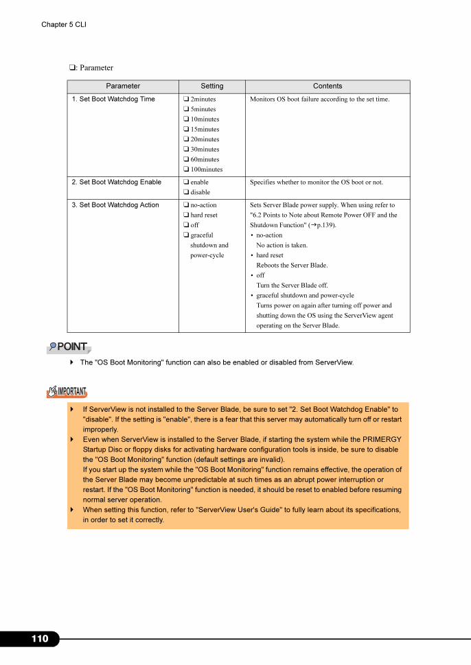
1
Chapter 5 CLI
❑: Parameter
� The "OS Boot Monitoring" function can also be enabled or disabled from ServerView.
Parameter Setting Contents
1. Set Boot Watchdog Time ❑ 2minutes
❑ 5minutes
❑ 10minutes
❑ 15minutes
❑ 20minutes
❑ 30minutes
❑ 60minutes
❑ 100minutes
Monitors OS boot failure according to the set time.
2. Set Boot Watchdog Enable ❑ enable
❑ disable
Specifies whether to monitor the OS boot or not.
3. Set Boot Watchdog Action ❑ no-action
❑ hard reset
❑ off
❑ graceful
shutdown and
power-cycle
Sets Server Blade power supply. When using refer to
"6.2 Points to Note about Remote Power OFF and the
Shutdown Function" (�p.139).
• no-action
No action is taken.
• hard reset
Reboots the Server Blade.
• off
Turn the Server Blade off.
• graceful shutdown and power-cycle
Turns power on again after turning off power and
shutting down the OS using the ServerView agent
operating on the Server Blade.
� If ServerView is not installed to the Server Blade, be sure to set "2. Set Boot Watchdog Enable" to
"disable". If the setting is "enable", there is a fear that this server may automatically turn off or restart
improperly.
� Even when ServerView is installed to the Server Blade, if starting the system while the PRIMERGY
Startup Disc or floppy disks for activating hardware configuration tools is inside, be sure to disable
the "OS Boot Monitoring" function (default settings are invalid).
If you start up the system while the "OS Boot Monitoring" function remains effective, the operation of
the Server Blade may become unpredictable at such times as an abrupt power interruption or
restart. If the "OS Boot Monitoring" function is needed, it should be reset to enabled before resuming
normal server operation.
� When setting this function, refer to "ServerView User's Guide" to fully learn about its specifications,
in order to set it correctly.
10
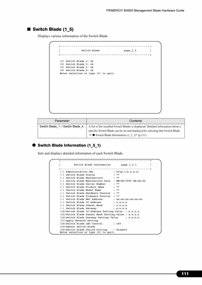
PRIMERGY BX600 Management Blade Hardware Guide
■ Switch Blade (1_5)
Displays various information of the Switch Blade.
● Switch Blade Information (1_5_1)
Sets and displays detailed information of each Switch Blade.
Parameter Contents
Switch Blade_1 – Switch Blade_4 A list of the installed Switch Blades is displayed. Detailed information about a
specific Switch Blade can be set and displayed by selecting that Switch Blade.
�"● Switch Blade Information (1_5_1)" (p.111)
Switch Blade page_1_5
(1) Switch Blade_1: ok(2) Switch Blade_2: ok(3) Switch Blade_3: ok(4) Switch Blade_4: okEnter selection or type (0) to quit:
+------------------------------------------+| |+------------------------------------------+
Switch Blade Information page_1_5_1
(-) Administrative URL : http://n.n.n.n/(-) Switch Blade Status : **(-) Switch Blade Manufacture : **(-) Switch Blade Manufacture Date : MM/DD/YYYY HH:DD:SS(-) Switch Blade Serial Number : **(-) Switch Blade Product Name : **(-) Switch Blade Model Name : **(-) Switch Blade Hardware Version : **(-) Switch Blade Firmware Version : **(-) Switch Blade MAC Address : nn:nn:nn:nn:nn:nn(-) Switch Blade IP Address : n.n.n.n(-) Switch Blade Subnet Mask : n.n.n.n(-) Switch Blade Gateway : n.n.n.n(14)Switch Blade IP Address Setting Value : n.n.n.n(15)Switch Blade Subnet Mask Setting Value : n.n.n.n(16)Switch Blade Gateway Setting Value : n.n.n.n(17)Apply Network Setting(18)Switch Blade LED Control : off(19)Reboot Switch Blade(20)Switch Blade Period Polling : disableEnter selection or type (0) to quit:
+------------------------------------------+| |+------------------------------------------+
111
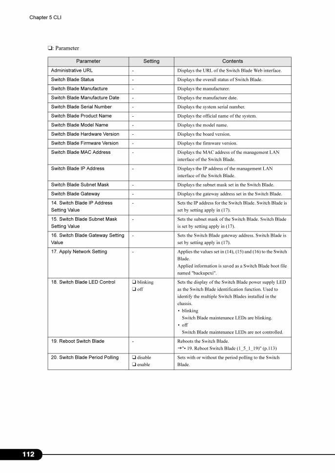
1
Chapter 5 CLI
❑: Parameter
Parameter Setting Contents
Administrative URL - Displays the URL of the Switch Blade Web interface.
Switch Blade Status - Displays the overall status of Switch Blade.
Switch Blade Manufacture - Displays the manufacturer.
Switch Blade Manufacture Date - Displays the manufacture date.
Switch Blade Serial Number - Displays the system serial number.
Switch Blade Product Name - Displays the official name of the system.
Switch Blade Model Name - Displays the model name.
Switch Blade Hardware Version - Displays the board version.
Switch Blade Firmware Version - Displays the firmware version.
Switch Blade MAC Address - Displays the MAC address of the management LAN
interface of the Switch Blade.
Switch Blade IP Address - Displays the IP address of the management LAN
interface of the Switch Blade.
Switch Blade Subnet Mask - Displays the subnet mask set in the Switch Blade.
Switch Blade Gateway - Displays the gateway address set in the Switch Blade.
14. Switch Blade IP Address
Setting Value
- Sets the IP address for the Switch Blade. Switch Blade is
set by setting apply in (17).
15. Switch Blade Subnet Mask
Setting Value
- Sets the subnet mask of the Switch Blade. Switch Blade
is set by setting apply in (17).
16. Switch Blade Gateway Setting
Value
- Sets the Switch Blade gateway address. Switch Blade is
set by setting apply in (17).
17. Apply Network Setting - Applies the values set in (14), (15) and (16) to the Switch
Blade.
Applied information is saved as a Switch Blade boot file
named "backupexi".
18. Switch Blade LED Control ❑ blinking
❑ off
Sets the display of the Switch Blade power supply LED
as the Switch Blade identification function. Used to
identify the multiple Switch Blades installed in the
chassis.
• blinking
Switch Blade maintenance LEDs are blinking.
• off
Switch Blade maintenance LEDs are not controlled.
19. Reboot Switch Blade - Reboots the Switch Blade.
�"• 19. Reboot Switch Blade (1_5_1_19)" (p.113)
20. Switch Blade Period Polling ❑ disable
❑ enable
Sets with or without the period polling to the Switch
Blade.
12
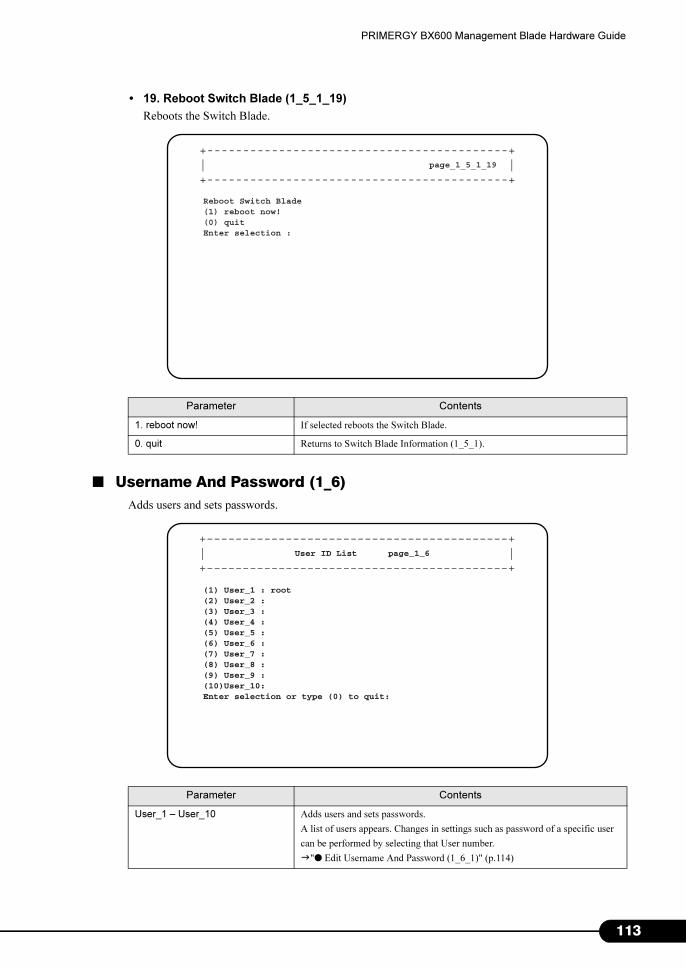
PRIMERGY BX600 Management Blade Hardware Guide
• 19. Reboot Switch Blade (1_5_1_19)
Reboots the Switch Blade.
■ Username And Password (1_6)
Adds users and sets passwords.
Parameter Contents
1. reboot now! If selected reboots the Switch Blade.
0. quit Returns to Switch Blade Information (1_5_1).
Parameter Contents
User_1 – User_10 Adds users and sets passwords.
A list of users appears. Changes in settings such as password of a specific user
can be performed by selecting that User number.
�"● Edit Username And Password (1_6_1)" (p.114)
page_1_5_1_19
Reboot Switch Blade(1) reboot now!(0) quitEnter selection :
+------------------------------------------+| |+------------------------------------------+
User ID List page_1_6
(1) User_1 : root(2) User_2 :(3) User_3 :(4) User_4 :(5) User_5 :(6) User_6 :(7) User_7 :(8) User_8 :(9) User_9 :(10)User_10:Enter selection or type (0) to quit:
+------------------------------------------+| |+------------------------------------------+
113
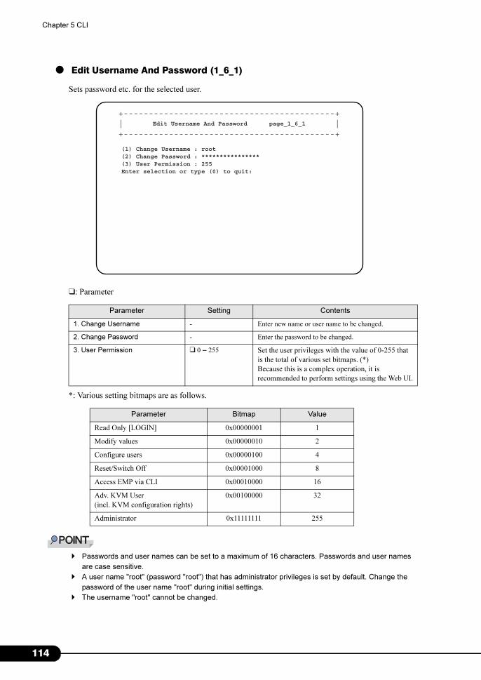
1
Chapter 5 CLI
● Edit Username And Password (1_6_1)
Sets password etc. for the selected user.
❑: Parameter
*: Various setting bitmaps are as follows.
� Passwords and user names can be set to a maximum of 16 characters. Passwords and user names
are case sensitive.
� A user name "root" (password "root") that has administrator privileges is set by default. Change the
password of the user name "root" during initial settings.
� The username "root" cannot be changed.
Parameter Setting Contents
1. Change Username - Enter new name or user name to be changed.
2. Change Password - Enter the password to be changed.
3. User Permission ❑ 0 – 255 Set the user privileges with the value of 0-255 that
is the total of various set bitmaps. (*)
Because this is a complex operation, it is
recommended to perform settings using the Web UI.
Parameter Bitmap Value
Read Only [LOGIN] 0x00000001 1
Modify values 0x00000010 2
Configure users 0x00000100 4
Reset/Switch Off 0x00001000 8
Access EMP via CLI 0x00010000 16
Adv. KVM User
(incl. KVM configuration rights)
0x00100000 32
Administrator 0x11111111 255
Edit Username And Password page_1_6_1
(1) Change Username : root(2) Change Password : ****************(3) User Permission : 255Enter selection or type (0) to quit:
+------------------------------------------+| |+------------------------------------------+
14
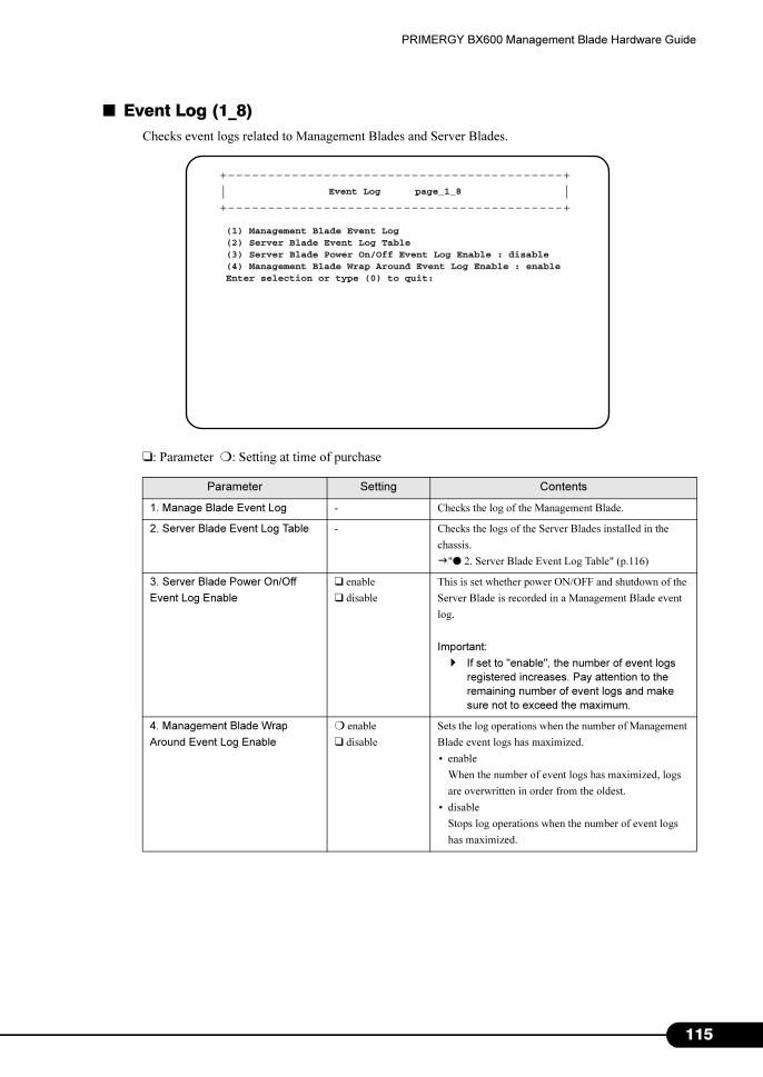
PRIMERGY BX600 Management Blade Hardware Guide
■ Event Log (1_8)
Checks event logs related to Management Blades and Server Blades.
❑: Parameter ❍: Setting at time of purchase
Parameter Setting Contents
1. Manage Blade Event Log - Checks the log of the Management Blade.
2. Server Blade Event Log Table - Checks the logs of the Server Blades installed in the
chassis.
�"● 2. Server Blade Event Log Table" (p.116)
3. Server Blade Power On/Off
Event Log Enable
❑ enable
❑ disable
This is set whether power ON/OFF and shutdown of the
Server Blade is recorded in a Management Blade event
log.
Important:
� If set to "enable", the number of event logs
registered increases. Pay attention to the
remaining number of event logs and make
sure not to exceed the maximum.
4. Management Blade Wrap
Around Event Log Enable
❍ enable
❑ disable
Sets the log operations when the number of Management
Blade event logs has maximized.
• enable
When the number of event logs has maximized, logs
are overwritten in order from the oldest.
• disable
Stops log operations when the number of event logs
has maximized.
Event Log page_1_8
(1) Management Blade Event Log(2) Server Blade Event Log Table(3) Server Blade Power On/Off Event Log Enable : disable(4) Management Blade Wrap Around Event Log Enable : enableEnter selection or type (0) to quit:
+------------------------------------------+| |+------------------------------------------+
115
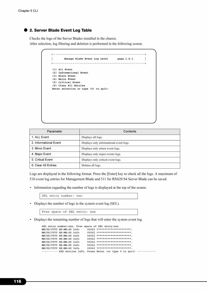
1
Chapter 5 CLI
● 2. Server Blade Event Log Table
Checks the logs of the Server Blades installed in the chassis.
After selection, log filtering and deletion is performed in the following screen.
Logs are displayed in the following format. Press the [Enter] key to check all the logs. A maximum of
510 event log entries for Management Blade and 511 for BX620 S4 Server Blade can be saved.
• Information regarding the number of logs is displayed at the top of the screen.
• Displays the number of logs in the system event log (SEL).
• Displays the remaining number of logs that will enter the system event log.
Parameter Contents
1. ALL Event Displays all logs.
2. Informational Event Displays only informational event logs.
3. Minor Event Displays only minor event logs.
4. Major Event Displays only major events logs.
5. Critical Event Displays only critical event logs.
6. Clear All Entries Deletes all logs.
SEL entry number: nnn
Free space of SEL entry: nnn
Manage Blade Event Log Level page_1_8_1
(1) All Event(2) Informational Event(3) Minor Event(4) Major Event(5) Critical Event(6) Clear All EntriesEnter selection or type (0) to quit:
+------------------------------------------+| |+------------------------------------------+
SEL entry number:nnn, Free space of SEL entry:nnnMM/DD/YYYY HH:MM:SS Info 00062 **********************.MM/DD/YYYY HH:MM:SS Info 00062 **********************.MM/DD/YYYY HH:MM:SS Info 00062 **********************.MM/DD/YYYY HH:MM:SS Info 00062 **********************.MM/DD/YYYY HH:MM:SS Info 00062 **********************.MM/DD/YYYY HH:MM:SS Info 00062 **********************.MM/DD/YYYY HH:MM:SS Info 00062 **********************.---------- XXX entries left, Press Enter (or type 0 to quit) ------------
16
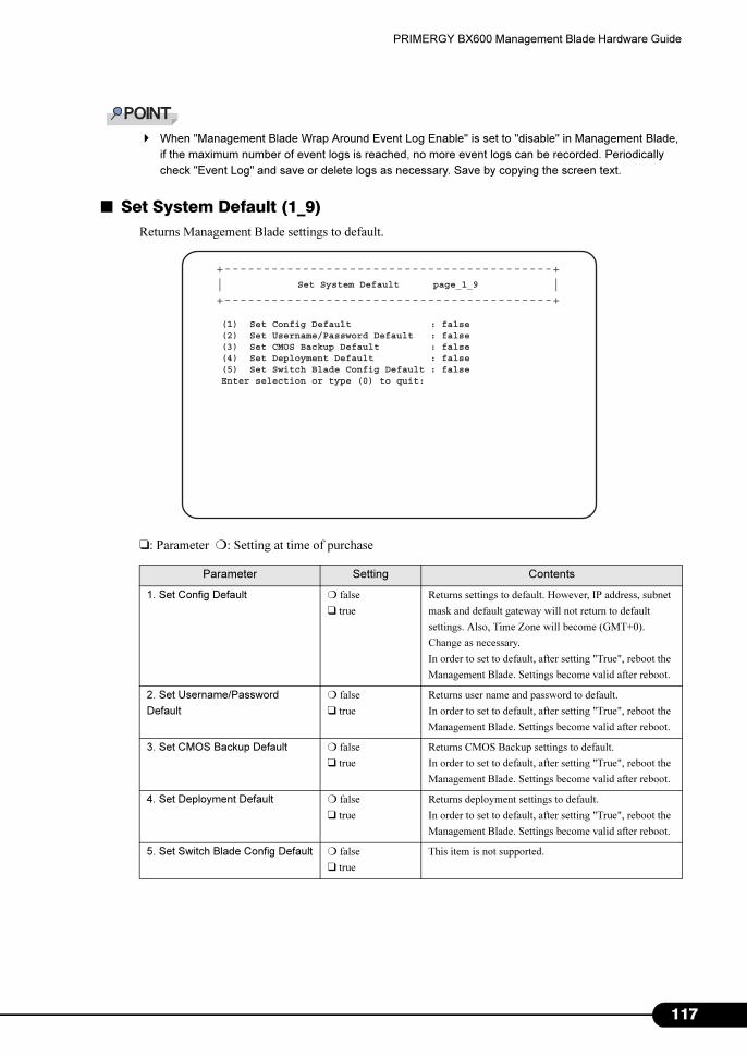
PRIMERGY BX600 Management Blade Hardware Guide
� When "Management Blade Wrap Around Event Log Enable" is set to "disable" in Management Blade,
if the maximum number of event logs is reached, no more event logs can be recorded. Periodically
check "Event Log" and save or delete logs as necessary. Save by copying the screen text.
■ Set System Default (1_9)
Returns Management Blade settings to default.
❑: Parameter ❍: Setting at time of purchase
Parameter Setting Contents
1. Set Config Default ❍ false
❑ true
Returns settings to default. However, IP address, subnet
mask and default gateway will not return to default
settings. Also, Time Zone will become (GMT+0).
Change as necessary.
In order to set to default, after setting "True", reboot the
Management Blade. Settings become valid after reboot.
2. Set Username/Password
Default
❍ false
❑ true
Returns user name and password to default.
In order to set to default, after setting "True", reboot the
Management Blade. Settings become valid after reboot.
3. Set CMOS Backup Default ❍ false
❑ true
Returns CMOS Backup settings to default.
In order to set to default, after setting "True", reboot the
Management Blade. Settings become valid after reboot.
4. Set Deployment Default ❍ false
❑ true
Returns deployment settings to default.
In order to set to default, after setting "True", reboot the
Management Blade. Settings become valid after reboot.
5. Set Switch Blade Config Default ❍ false
❑ true
This item is not supported.
Set System Default page_1_9
(1) Set Config Default : false(2) Set Username/Password Default : false(3) Set CMOS Backup Default : false(4) Set Deployment Default : false(5) Set Switch Blade Config Default : falseEnter selection or type (0) to quit:
+------------------------------------------+| |+------------------------------------------+
117
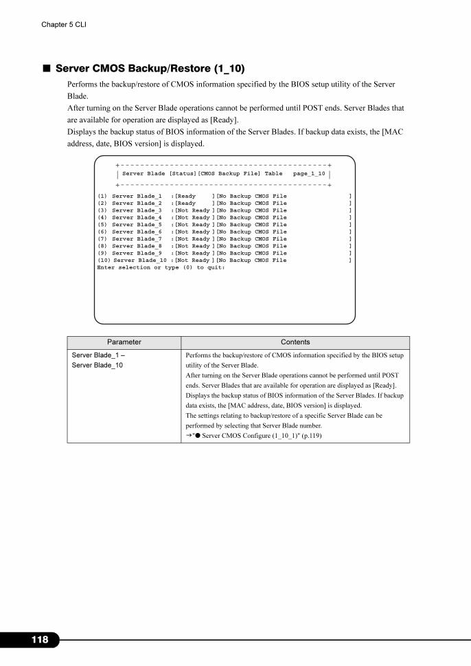
1
Chapter 5 CLI
■ Server CMOS Backup/Restore (1_10)
Performs the backup/restore of CMOS information specified by the BIOS setup utility of the Server
Blade.
After turning on the Server Blade operations cannot be performed until POST ends. Server Blades that
are available for operation are displayed as [Ready].
Displays the backup status of BIOS information of the Server Blades. If backup data exists, the [MAC
address, date, BIOS version] is displayed.
Parameter Contents
Server Blade_1 –
Server Blade_10
Performs the backup/restore of CMOS information specified by the BIOS setup
utility of the Server Blade.
After turning on the Server Blade operations cannot be performed until POST
ends. Server Blades that are available for operation are displayed as [Ready].
Displays the backup status of BIOS information of the Server Blades. If backup
data exists, the [MAC address, date, BIOS version] is displayed.
The settings relating to backup/restore of a specific Server Blade can be
performed by selecting that Server Blade number.
�"● Server CMOS Configure (1_10_1)" (p.119)
+------------------------------------------+| |+------------------------------------------+
Server Blade [Status][CMOS Backup File] Table page_1_10
(1) Server Blade_1 :[Ready ][No Backup CMOS File ](2) Server Blade_2 :[Ready ][No Backup CMOS File ](3) Server Blade_3 :[Not Ready ][No Backup CMOS File ](4) Server Blade_4 :[Not Ready ][No Backup CMOS File ](5) Server Blade_5 :[Not Ready ][No Backup CMOS File ](6) Server Blade_6 :[Not Ready ][No Backup CMOS File ](7) Server Blade_7 :[Not Ready ][No Backup CMOS File ](8) Server Blade_8 :[Not Ready ][No Backup CMOS File ](9) Server Blade_9 :[Not Ready ][No Backup CMOS File ](10) Server Blade_10 :[Not Ready ][No Backup CMOS File ]
Enter selection or type (0) to quit:
18
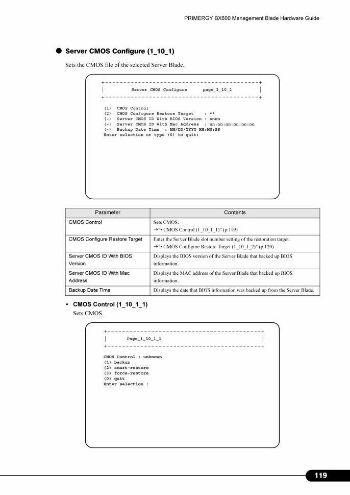
PRIMERGY BX600 Management Blade Hardware Guide
● Server CMOS Configure (1_10_1)
Sets the CMOS file of the selected Server Blade.
• CMOS Control (1_10_1_1)
Sets CMOS.
Parameter Contents
CMOS Control Sets CMOS.
�"• CMOS Control (1_10_1_1)" (p.119)
CMOS Configure Restore Target Enter the Server Blade slot number setting of the restoration target.
�"• CMOS Configure Restore Target (1_10_1_2)" (p.120)
Server CMOS ID With BIOS
Version
Displays the BIOS version of the Server Blade that backed up BIOS
information.
Server CMOS ID With Mac
Address
Displays the MAC address of the Server Blade that backed up BIOS
information.
Backup Date Time Displays the date that BIOS information was backed up from the Server Blade.
+------------------------------------------+| |+------------------------------------------+
Server CMOS Configure page_1_10_1
(1) CMOS Control(2) CMOS Configure Restore Target : **(-) Server CMOS ID With BIOS Version : nnnn(-) Server CMOS ID With Mac Address : nn:nn:nn:nn:nn:nn(-) Backup Date Time : MM/DD/YYYY HH:MM:SSEnter selection or type (0) to quit:
+------------------------------------------+| |+------------------------------------------+
Page_1_10_1_1
CMOS Control : unknown(1) backup(2) smart-restore(3) force-restore(0) quitEnter selection :
119
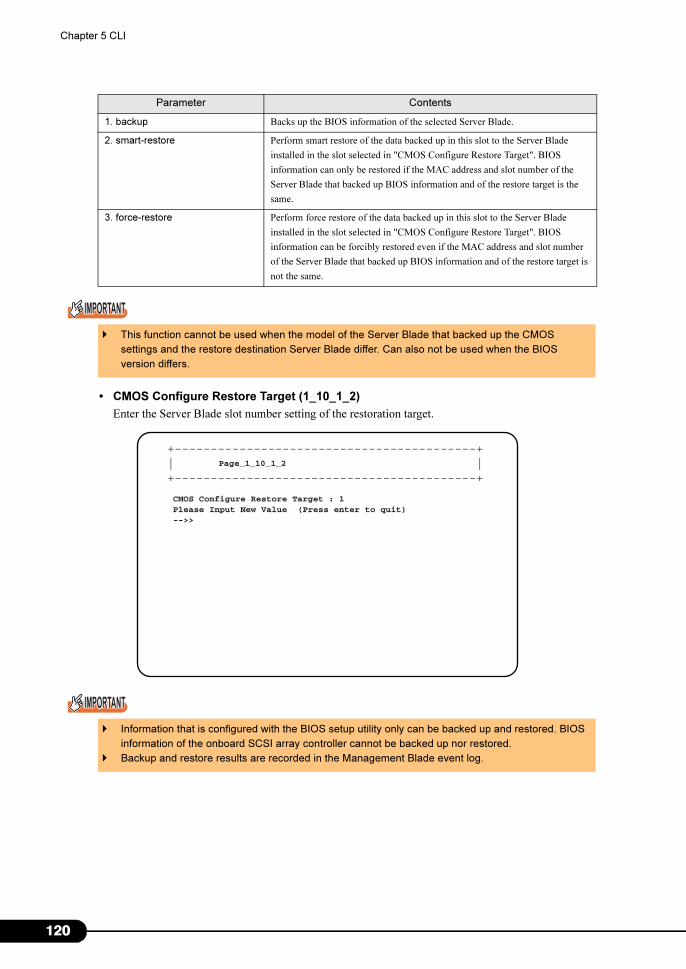
1
Chapter 5 CLI
• CMOS Configure Restore Target (1_10_1_2)
Enter the Server Blade slot number setting of the restoration target.
Parameter Contents
1. backup Backs up the BIOS information of the selected Server Blade.
2. smart-restore Perform smart restore of the data backed up in this slot to the Server Blade
installed in the slot selected in "CMOS Configure Restore Target". BIOS
information can only be restored if the MAC address and slot number of the
Server Blade that backed up BIOS information and of the restore target is the
same.
3. force-restore Perform force restore of the data backed up in this slot to the Server Blade
installed in the slot selected in "CMOS Configure Restore Target". BIOS
information can be forcibly restored even if the MAC address and slot number
of the Server Blade that backed up BIOS information and of the restore target is
not the same.
� This function cannot be used when the model of the Server Blade that backed up the CMOS
settings and the restore destination Server Blade differ. Can also not be used when the BIOS
version differs.
� Information that is configured with the BIOS setup utility only can be backed up and restored. BIOS
information of the onboard SCSI array controller cannot be backed up nor restored.
� Backup and restore results are recorded in the Management Blade event log.
+------------------------------------------+| |+------------------------------------------+
Page_1_10_1_2
CMOS Configure Restore Target : 1Please Input New Value (Press enter to quit)-->>
20
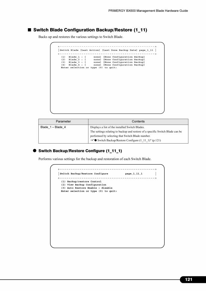
PRIMERGY BX600 Management Blade Hardware Guide
■ Switch Blade Configuration Backup/Restore (1_11)
Backs up and restores the various settings to Switch Blade.
● Switch Backup/Restore Configure (1_11_1)
Performs various settings for the backup and restoration of each Switch Blade.
Parameter Contents
Blade_1 – Blade_4 Displays a list of the installed Switch Blades.
The settings relating to backup and restore of a specific Switch Blade can be
performed by selecting that Switch Blade number.
�"● Switch Backup/Restore Configure (1_11_1)" (p.121)
+--------------------------------------------+| |+--------------------------------------------+Switch Blade [Last Action] [Last Done Backup Date] page_1_11
(1) Blade_1 : [ none] [None Configuration Backup](2) Blade_2 : [ none] [None Configuration Backup](3) Blade_3 : [ none] [None Configuration Backup](4) Blade_4 : [ none] [None Configuration Backup]Enter selection or type (0) to quit:
+--------------------------------------------+| |+--------------------------------------------+Switch Backup/Restore Configure page_1_11_1
(1) Backup/restore Control(2) View Backup Configuration(3) Auto Restore Enable : disableEnter selection or type (0) to quit:
121
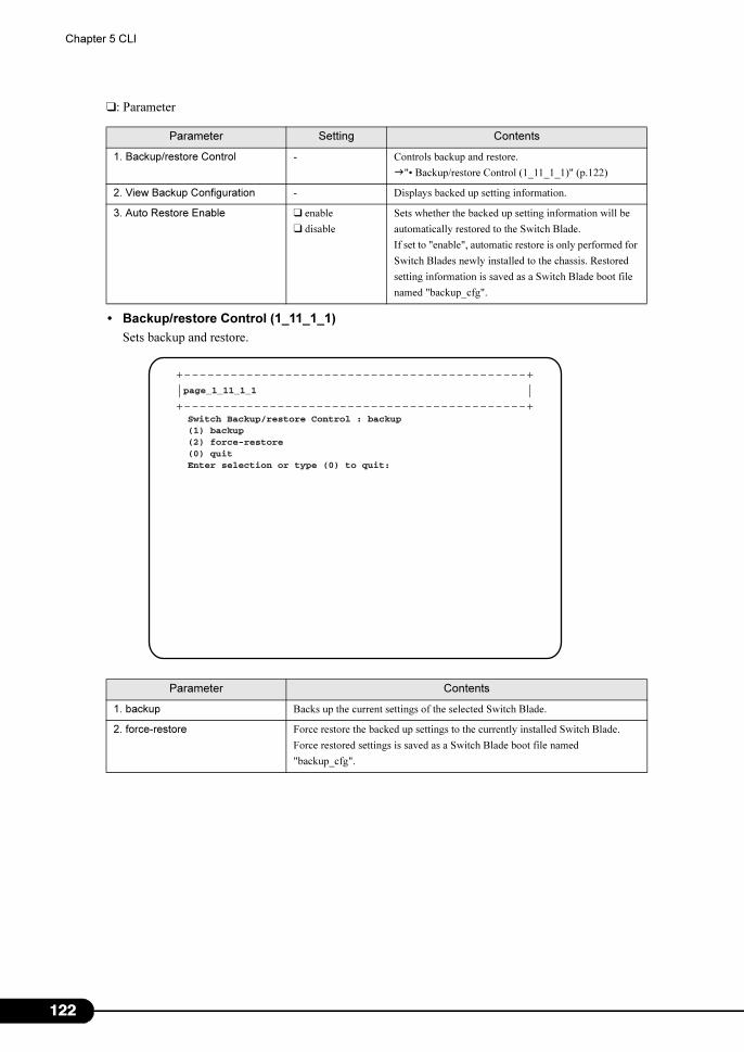
1
Chapter 5 CLI
❑: Parameter
• Backup/restore Control (1_11_1_1)
Sets backup and restore.
Parameter Setting Contents
1. Backup/restore Control - Controls backup and restore.
�"• Backup/restore Control (1_11_1_1)" (p.122)
2. View Backup Configuration - Displays backed up setting information.
3. Auto Restore Enable ❑ enable
❑ disable
Sets whether the backed up setting information will be
automatically restored to the Switch Blade.
If set to "enable", automatic restore is only performed for
Switch Blades newly installed to the chassis. Restored
setting information is saved as a Switch Blade boot file
named "backup_cfg".
Parameter Contents
1. backup Backs up the current settings of the selected Switch Blade.
2. force-restore Force restore the backed up settings to the currently installed Switch Blade.
Force restored settings is saved as a Switch Blade boot file named
"backup_cfg".
+--------------------------------------------+| |+--------------------------------------------+page_1_11_1_1
Switch Backup/restore Control : backup (1) backup (2) force-restore(0) quitEnter selection or type (0) to quit:
22
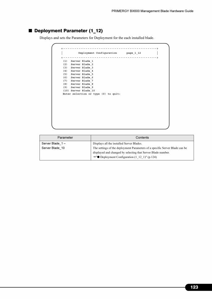
PRIMERGY BX600 Management Blade Hardware Guide
■ Deployment Parameter (1_12)
Displays and sets the Parameters for Deployment for the each installed blade.
Parameter Contents
Server Blade_1 –
Server Blade_10
Displays all the installed Server Blades.
The settings of the deployment Parameters of a specific Server Blade can be
displayed and changed by selecting that Server Blade number.
�"● Deployment Configuration (1_12_1)" (p.124)
+------------------------------------------+| |+------------------------------------------+
Deployment Configuration page_1_12
(1) Server Blade_1(2) Server Blade_2(3) Server Blade_3(4) Server Blade_4(5) Server Blade_5(6) Server Blade_6(7) Server Blade_7(8) Server Blade_8(9) Server Blade_9(10) Server Blade_10Enter selection or type (0) to quit:
123
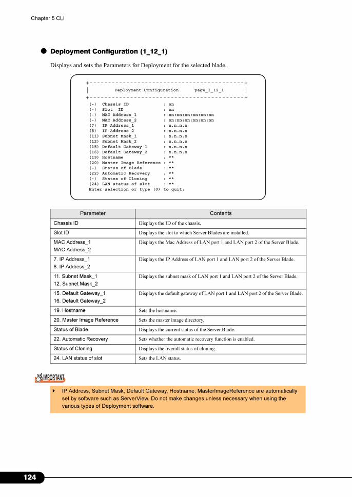
1
Chapter 5 CLI
● Deployment Configuration (1_12_1)
Displays and sets the Parameters for Deployment for the selected blade.
Parameter Contents
Chassis ID Displays the ID of the chassis.
Slot ID Displays the slot to which Server Blades are installed.
MAC Address_1
MAC Address_2
Displays the Mac Address of LAN port 1 and LAN port 2 of the Server Blade.
7. IP Address_1
8. IP Address_2
Displays the IP Address of LAN port 1 and LAN port 2 of the Server Blade.
11. Subnet Mask_1
12. Subnet Mask_2
Displays the subnet mask of LAN port 1 and LAN port 2 of the Server Blade.
15. Default Gateway_1
16. Default Gateway_2
Displays the default gateway of LAN port 1 and LAN port 2 of the Server Blade.
19. Hostname Sets the hostname.
20. Master Image Reference Sets the master image directory.
Status of Blade Displays the current status of the Server Blade.
22. Automatic Recovery Sets whether the automatic recovery function is enabled.
Status of Cloning Displays the overall status of cloning.
24. LAN status of slot Sets the LAN status.
� IP Address, Subnet Mask, Default Gateway, Hostname, MasterImageReference are automatically
set by software such as ServerView. Do not make changes unless necessary when using the
various types of Deployment software.
+------------------------------------------+| |+------------------------------------------+
Deployment Configuration page_1_12_1
(-) Chassis ID : nn(-) Slot ID : nn(-) MAC Address_1 : nn:nn:nn:nn:nn:nn(-) MAC Address_2 : nn:nn:nn:nn:nn:nn(7) IP Address_1 : n.n.n.n(8) IP Address_2 : n.n.n.n(11) Subnet Mask_1 : n.n.n.n(12) Subnet Mask_2 : n.n.n.n(15) Default Gateway_1 : n.n.n.n(16) Default Gateway_2 : n.n.n.n(19) Hostname : **(20) Master Image Reference : **(-) Status of Blade : **(22) Automatic Recovery : **(-) States of Cloning : **(24) LAN status of slot : **Enter selection or type (0) to quit:
24
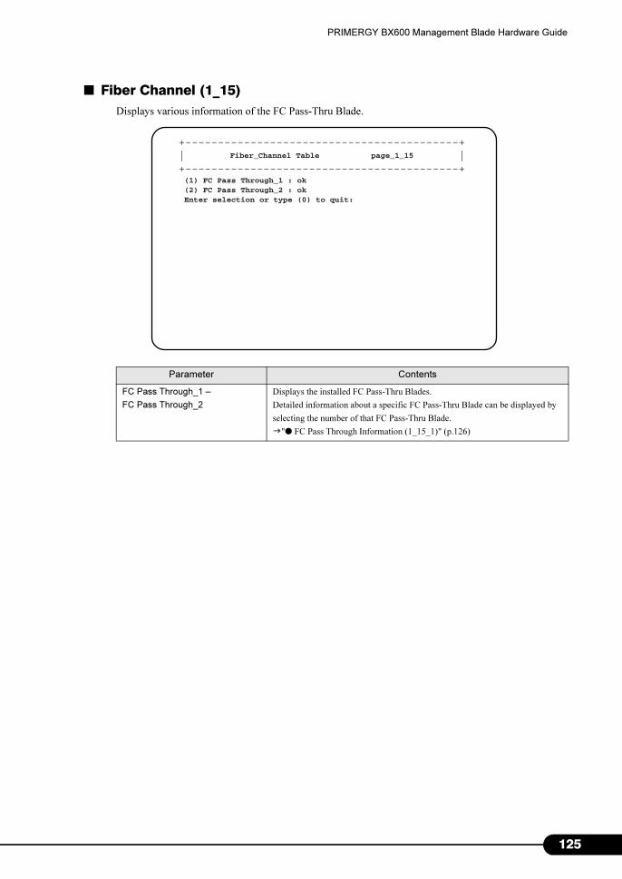
PRIMERGY BX600 Management Blade Hardware Guide
■ Fiber Channel (1_15)
Displays various information of the FC Pass-Thru Blade.
Parameter Contents
FC Pass Through_1 –
FC Pass Through_2
Displays the installed FC Pass-Thru Blades.
Detailed information about a specific FC Pass-Thru Blade can be displayed by
selecting the number of that FC Pass-Thru Blade.
�"● FC Pass Through Information (1_15_1)" (p.126)
+------------------------------------------+| |+------------------------------------------+
Fiber_Channel Table page_1_15
(1) FC Pass Through_1 : ok(2) FC Pass Through_2 : okEnter selection or type (0) to quit:
125
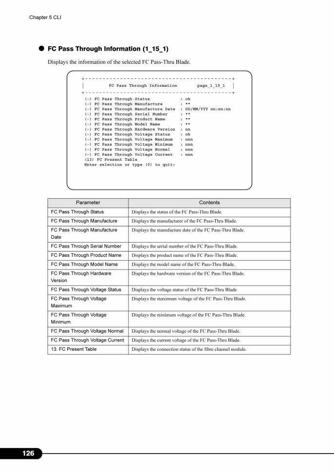
1
Chapter 5 CLI
● FC Pass Through Information (1_15_1)
Displays the information of the selected FC Pass-Thru Blade.
Parameter Contents
FC Pass Through Status Displays the status of the FC Pass-Thru Blade.
FC Pass Through Manufacture Displays the manufacturer of the FC Pass-Thru Blade.
FC Pass Through Manufacture
Date
Displays the manufacture date of the FC Pass-Thru Blade.
FC Pass Through Serial Number Displays the serial number of the FC Pass-Thru Blade.
FC Pass Through Product Name Displays the product name of the FC Pass-Thru Blade.
FC Pass Through Model Name Displays the model name of the FC Pass-Thru Blade.
FC Pass Through Hardware
Version
Displays the hardware version of the FC Pass-Thru Blade.
FC Pass Through Voltage Status Displays the voltage status of the FC Pass-Thru Blade.
FC Pass Through Voltage
Maximum
Displays the maximum voltage of the FC Pass-Thru Blade.
FC Pass Through Voltage
Minimum
Displays the minimum voltage of the FC Pass-Thru Blade.
FC Pass Through Voltage Normal Displays the normal voltage of the FC Pass-Thru Blade.
FC Pass Through Voltage Current Displays the current voltage of the FC Pass-Thru Blade.
13. FC Present Table Displays the connection status of the fibre channel module.
+------------------------------------------+| |+------------------------------------------+
FC Pass Through Information page_1_15_1
(-) FC Pass Through Status : ok(-) FC Pass Through Manufacture : **(-) FC Pass Through Manufacture Date : DD/MM/YYY nn:nn:nn(-) FC Pass Through Serial Number : **(-) FC Pass Through Product Name : **(-) FC Pass Through Model Name : **(-) FC Pass Through Hardware Version : nn(-) FC Pass Through Voltage Status : ok(-) FC Pass Through Voltage Maximum : nnn(-) FC Pass Through Voltage Minimum : nnn(-) FC Pass Through Voltage Normal : nnn(-) FC Pass Through Voltage Current : nnn(13) FC Present TableEnter selection or type (0) to quit:
26
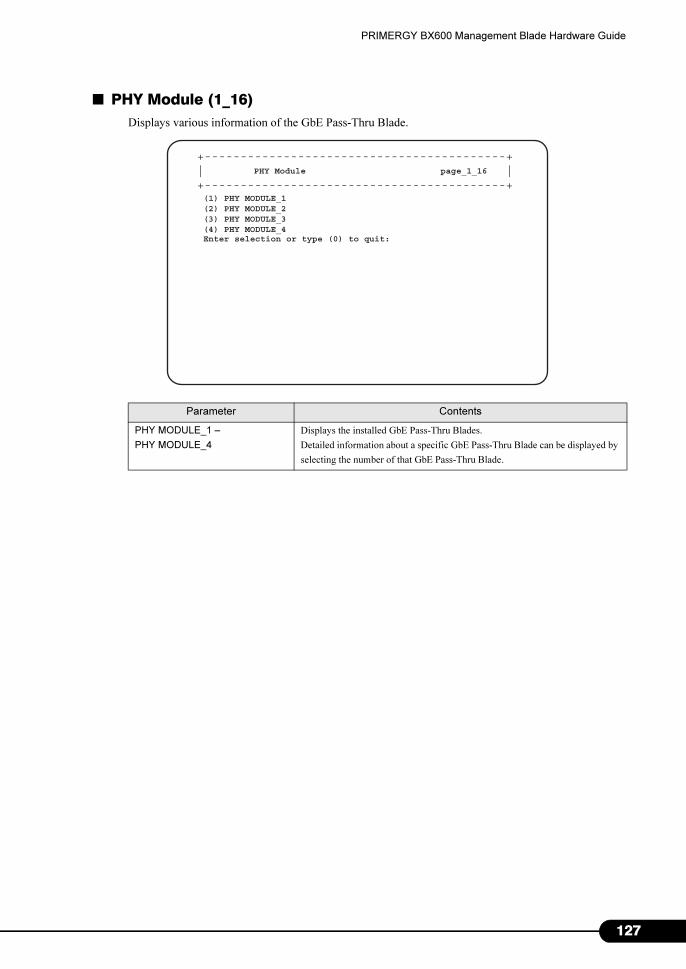
PRIMERGY BX600 Management Blade Hardware Guide
■ PHY Module (1_16)
Displays various information of the GbE Pass-Thru Blade.
Parameter Contents
PHY MODULE_1 –
PHY MODULE_4
Displays the installed GbE Pass-Thru Blades.
Detailed information about a specific GbE Pass-Thru Blade can be displayed by
selecting the number of that GbE Pass-Thru Blade.
+------------------------------------------+| |+------------------------------------------+
PHY Module page_1_16
(1) PHY MODULE_1(2) PHY MODULE_2(3) PHY MODULE_3(4) PHY MODULE_4Enter selection or type (0) to quit:
127
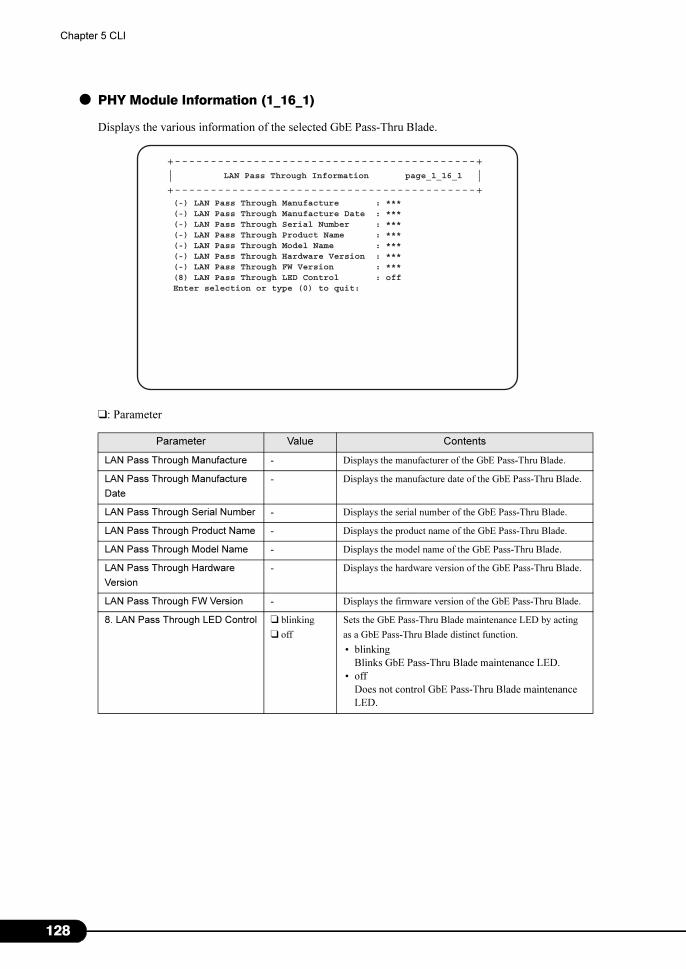
1
Chapter 5 CLI
● PHY Module Information (1_16_1)
Displays the various information of the selected GbE Pass-Thru Blade.
❑: Parameter
Parameter Value Contents
LAN Pass Through Manufacture - Displays the manufacturer of the GbE Pass-Thru Blade.
LAN Pass Through Manufacture
Date
- Displays the manufacture date of the GbE Pass-Thru Blade.
LAN Pass Through Serial Number - Displays the serial number of the GbE Pass-Thru Blade.
LAN Pass Through Product Name - Displays the product name of the GbE Pass-Thru Blade.
LAN Pass Through Model Name - Displays the model name of the GbE Pass-Thru Blade.
LAN Pass Through Hardware
Version
- Displays the hardware version of the GbE Pass-Thru Blade.
LAN Pass Through FW Version - Displays the firmware version of the GbE Pass-Thru Blade.
8. LAN Pass Through LED Control ❑ blinking
❑ off
Sets the GbE Pass-Thru Blade maintenance LED by acting
as a GbE Pass-Thru Blade distinct function.
• blinking
Blinks GbE Pass-Thru Blade maintenance LED.
• off
Does not control GbE Pass-Thru Blade maintenance
LED.
+------------------------------------------+| |+------------------------------------------+
LAN Pass Through Information page_1_16_1
(-) LAN Pass Through Manufacture : ***(-) LAN Pass Through Manufacture Date : ***(-) LAN Pass Through Serial Number : ***(-) LAN Pass Through Product Name : ***(-) LAN Pass Through Model Name : ***(-) LAN Pass Through Hardware Version : ***(-) LAN Pass Through FW Version : ***(8) LAN Pass Through LED Control : offEnter selection or type (0) to quit:
28
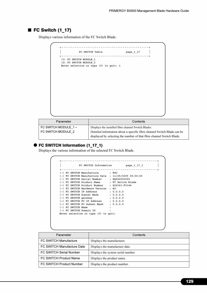
PRIMERGY BX600 Management Blade Hardware Guide
■ FC Switch (1_17)
Displays various information of the FC Switch Blade.
● FC SWITCH Information (1_17_1)
Displays the various information of the selected FC Switch Blade.
Parameter Contents
FC SWITCH MODULE_1 –
FC SWITCH MODULE_2
Displays the installed fibre channel Switch Blades.
Detailed information about a specific fibre channel Switch Blade can be
displayed by selecting the number of that fibre channel Switch Blade.
Parameter Contents
FC SWITCH Manufacture Displays the manufacturer.
FC SWITCH Manufacture Date Displays the manufacture date.
FC SWITCH Serial Number Displays the system serial number.
FC SWITCH Product Name Displays the product name.
FC SWITCH Product Number Displays the product number.
+----------------------------------------+| FC SWITCH Table page_1_17 |+----------------------------------------+ (1) FC SWITCH MODULE_1 (2) FC SWITCH MODULE_2 Enter selection or type (0) to quit: 1
+--------------------------------------------+| FC SWITCH Information page_1_17_1 |+--------------------------------------------+(-) FC SWITCH Manufacture : FSC(-) FC SWITCH Manufacture Date : 11/25/2005 00:00:00(-) FC SWITCH Serial Number : RQ040002505(-) FC SWITCH Product Name : FC Switch Blade(-) FC SWITCH Product Number : S26361-F3144(-) FC SWITCH Hardware Version : A0(-) FC SWITCH IP Address : 0.0.0.0(-) FC SWITCH Subnet Mask : 0.0.0.0(-) FC SWITCH gateway : 0.0.0.0(-) FC SWITCH FC IP Address : 0.0.0.0(-) FC SWITCH FC Subnet Mask : 0.0.0.0(-) FC SWITCH Name : (-) FC SWITCH Domain ID : Enter selection or type (0) to quit:
129
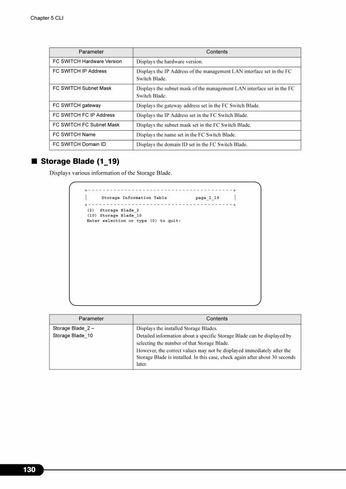
1
Chapter 5 CLI
■ Storage Blade (1_19)
Displays various information of the Storage Blade.
FC SWITCH Hardware Version Displays the hardware version.
FC SWITCH IP Address Displays the IP Address of the management LAN interface set in the FC
Switch Blade.
FC SWITCH Subnet Mask Displays the subnet mask of the management LAN interface set in the FC
Switch Blade.
FC SWITCH gateway Displays the gateway address set in the FC Switch Blade.
FC SWITCH FC IP Address Displays the IP Address set in the FC Switch Blade.
FC SWITCH FC Subnet Mask Displays the subnet mask set in the FC Switch Blade.
FC SWITCH Name Displays the name set in the FC Switch Blade.
FC SWITCH Domain ID Displays the domain ID set in the FC Switch Blade.
Parameter Contents
Storage Blade_2 –
Storage Blade_10
Displays the installed Storage Blades.
Detailed information about a specific Storage Blade can be displayed by
selecting the number of that Storage Blade.
However, the correct values may not be displayed immediately after the
Storage Blade is installed. In this case, check again after about 30 seconds
later.
Parameter Contents
+----------------------------------------+| Storage Information Table page_1_19 |+----------------------------------------+ (2) Storage Blade_2 (10) Storage Blade_10 Enter selection or type (0) to quit:
30
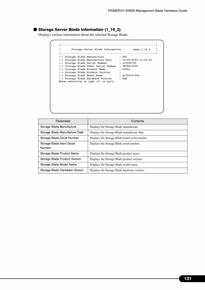
PRIMERGY BX600 Management Blade Hardware Guide
● Storage Server Blade Information (1_19_2)
Displays various information about the selected Storage Blade.
Parameter Contents
Storage Blade Manufacture Displays the Storage Blade manufacture.
Storage Blade Manufacture Date Displays the Storage Blade manufacture date.
Storage Blade Serial Number Displays the Storage Blade board serial number.
Storage Blade Ident Serial
Number
Displays the Storage Blade serial number.
Storage Blade Product Name Displays the Storage Blade product name.
Storage Blade Product Version Displays the Storage Blade product version.
Storage Blade Model Name Displays the Storage Blade model name.
Storage Blade Hardware Version Displays the Storage Blade hardware version.
+--------------------------------------------+| Storage Server Blade Information page_1_19_2 |+--------------------------------------------+(-) Storage Blade Manufacture : FSC(-) Storage Blade Manufacture Date : 05/20/2003 11:50:00(-) Storage Blade Serial Number : 123456789(-) Storage Blade Ident Serial Number : YKTS010000(-) Storage Blade Product Name : D2864(-) Storage Blade Product Version :(-) Storage Blade Model Name : A3C40097945(-) Storage Blade Hardware Version : XXXEnter selection or type (0) to quit:
131
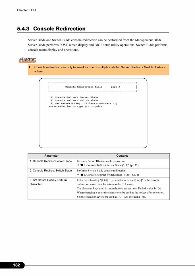
1
Chapter 5 CLI
5.4.3 Console Redirection
Server Blade and Switch Blade console redirection can be performed from the Management Blade.
Server Blade performs POST screen display and BIOS setup utility operations. Switch Blade performs
console menu display and operations.
� Console redirection can only be used for one of multiple installed Server Blades or Switch Blades at
a time.
Parameter Contents
1. Console Redirect Server Blade Performs Server Blade console redirection.
�"■ 1. Console Redirect Server Blade (3_1)" (p.133)
2. Console Redirect Switch Blade Performs Switch Blade console redirection.
�"■ 2. Console Redirect Switch Blade (3_2)" (p.134)
3. Set Return Hotkey, Ctrl+ (a
character)
Enter the return key "[Ctrl] + [(character to be used) key]" in the console
redirection screen enables return to the CLI screen.
The character keys used in return hotkey are set here. Default value is [Q].
When changing it enter the character to be used as the hotkey after selection.
Set the character keys to be used as [A] – [Z] excluding [M].
+------------------------------------------+| |+------------------------------------------+
Console Redirection Table page_3
(1) Console Redirect Server Blade(2) Console Redirect Switch Blade(3) Set Return Hotkey , Ctrl+(a character) : QEnter selection or type (0) to quit:
32
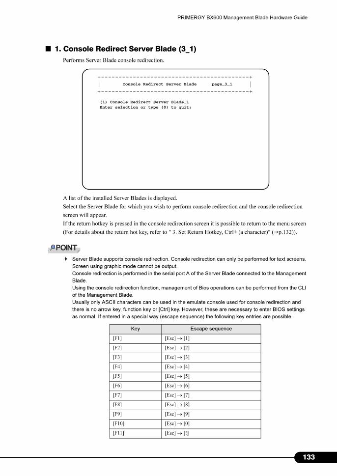
PRIMERGY BX600 Management Blade Hardware Guide
■ 1. Console Redirect Server Blade (3_1)
Performs Server Blade console redirection.
A list of the installed Server Blades is displayed.
Select the Server Blade for which you wish to perform console redirection and the console redirection
screen will appear.
If the return hotkey is pressed in the console redirection screen it is possible to return to the menu screen
(For details about the return hot key, refer to " 3. Set Return Hotkey, Ctrl+ (a character)" (�p.132)).
� Server Blade supports console redirection. Console redirection can only be performed for text screens.
Screen using graphic mode cannot be output.
Console redirection is performed in the serial port A of the Server Blade connected to the Management
Blade.
Using the console redirection function, management of Bios operations can be performed from the CLI
of the Management Blade.
Usually only ASCII characters can be used in the emulate console used for console redirection and
there is no arrow key, function key or [Ctrl] key. However, these are necessary to enter BIOS settings
as normal. If entered in a special way (escape sequence) the following key entries are possible.
Key Escape sequence
[F1] [Esc] → [1]
[F2] [Esc] → [2]
[F3] [Esc] → [3]
[F4] [Esc] → [4]
[F5] [Esc] → [5]
[F6] [Esc] → [6]
[F7] [Esc] → [7]
[F8] [Esc] → [8]
[F9] [Esc] → [9]
[F10] [Esc] → [0]
[F11] [Esc] → [!]
+------------------------------------------+| |+------------------------------------------+
Console Redirect Server Blade page_3_1
(1) Console Redirect Server Blade_1Enter selection or type (0) to quit:
133
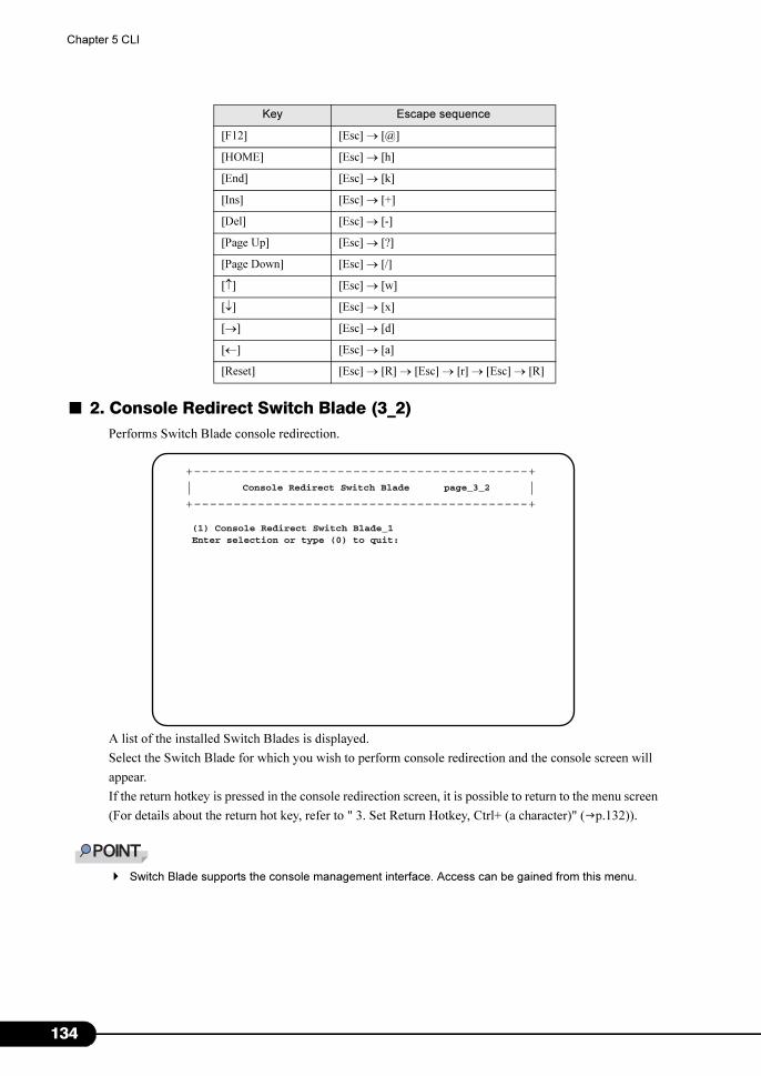
1
Chapter 5 CLI
■ 2. Console Redirect Switch Blade (3_2)
Performs Switch Blade console redirection.
A list of the installed Switch Blades is displayed.
Select the Switch Blade for which you wish to perform console redirection and the console screen will
appear.
If the return hotkey is pressed in the console redirection screen, it is possible to return to the menu screen
(For details about the return hot key, refer to " 3. Set Return Hotkey, Ctrl+ (a character)" (�p.132)).
� Switch Blade supports the console management interface. Access can be gained from this menu.
[F12] [Esc] → [@]
[HOME] [Esc] → [h]
[End] [Esc] → [k]
[Ins] [Esc] → [+]
[Del] [Esc] → [-]
[Page Up] [Esc] → [?]
[Page Down] [Esc] → [/]
[↑] [Esc] → [w]
[↓] [Esc] → [x]
[→] [Esc] → [d]
[←] [Esc] → [a]
[Reset] [Esc] → [R] → [Esc] → [r] → [Esc] → [R]
Key Escape sequence
+------------------------------------------+| |+------------------------------------------+
Console Redirect Switch Blade page_3_2
(1) Console Redirect Switch Blade_1Enter selection or type (0) to quit:
34
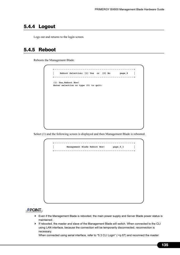
PRIMERGY BX600 Management Blade Hardware Guide
5.4.4 Logout
Logs out and returns to the login screen.
5.4.5 Reboot
Reboots the Management Blade.
Select (1) and the following screen is displayed and then Management Blade is rebooted.
L
� Even if the Management Blade is rebooted, the main power supply and Server Blade power status is
maintained.
� If rebooted, the master and slave of the Management Blade will switch. When connected to the CLI
using LAN interface, because the connection will be temporarily disconnected, reconnection is
necessary.
When connected using serial interface, refer to "5.3 CLI Login" (�p.67) and reconnect the master.
+------------------------------------------+| |+------------------------------------------+
Reboot Selection: [1] Yes or [0] No page_6
(1) Yes,Reboot Now!Enter selection or type (0) to quit:
+------------------------------------------+| |+------------------------------------------+
Management Blade Reboot Now! page_6_1
135
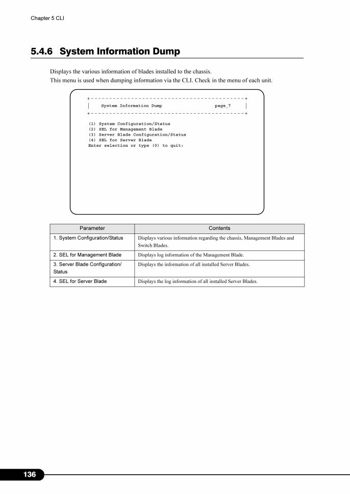
1
Chapter 5 CLI
5.4.6 System Information Dump
Displays the various information of blades installed to the chassis.
This menu is used when dumping information via the CLI. Check in the menu of each unit.
Parameter Contents
1. System Configuration/Status Displays various information regarding the chassis, Management Blades and
Switch Blades.
2. SEL for Management Blade Displays log information of the Management Blade.
3. Server Blade Configuration/
Status
Displays the information of all installed Server Blades.
4. SEL for Server Blade Displays the log information of all installed Server Blades.
+------------------------------------------+| |+------------------------------------------+
System Information Dump page_7
(1) System Configuration/Status(2) SEL for Management Blade(3) Server Blade Configuration/Status(4) SEL for Server BladeEnter selection or type (0) to quit:
36
Chapter 6
Technical Information Knowledgebase
This chapter explains the specifications and
operational notes of the Management Blade.
6.1 Specifications . . . . . . . . . . . . . . . . . . . . . . . . . . . . . . . . . 138
6.2 Points to Note about Remote Power OFF and the Shutdown
Function . . . . . . . . . . . . . . . . . . . . . . . . . . . . . . . . . . . . . 139
6.3 Other Notes . . . . . . . . . . . . . . . . . . . . . . . . . . . . . . . . . . 140
137

1
Chapter 6 Technical Information Knowledgebase
6.1 Specifications
The Management Blade is installed to the chassis by default. Specifications are as
follows.
Parameter Functions and Specifications
Product name Management blade
External interface LAN (10BASE-T/100BASE-TX) × 1, Serial × 1
Dimension (Length × Width × Height) 275 × 75 × 26 mm
Weight About 0.4kg
Operation environment This is the same as the operation environment for the chassis.
38

PRIMERGY BX600 Management Blade Hardware Guide
6.2 Points to Note about Remote Power OFF and the Shutdown Function
The following are points to note about remote power off and the shutdown function.
6.2.1 Remote Power OFF
This is a function in Management Blade that remotely turns OFF the power of the chassis and Server
Blade from the Web UI or CLI.
When using this function, note the following points.
• When remotely turning OFF the main power of the chassis, first check that the power of all the
installed Server Blades is OFF. If Server Blades are operational, the system may be damaged.
• When ordering Server Blade power to be turned OFF, first finish the OS on the Server Blade.
6.2.2 Graceful Shutdown Function
When using the graceful shutdown function, install ServerView to the Server Blade.
139
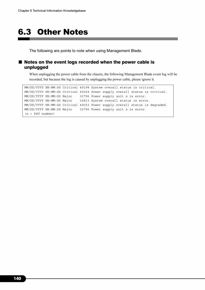
1
Chapter 6 Technical Information Knowledgebase
6.3 Other Notes
The following are points to note when using Management Blade.
■ Notes on the event logs recorded when the power cable is unplugged
When unplugging the power cable from the chassis, the following Management Blade event log will be
recorded, but because the log is caused by unplugging the power cable, please ignore it.
MM/DD/YYYY HH:MM:SS Critical 49198 System overall status is critical.
MM/DD/YYYY HH:MM:SS Critical 49254 Power supply overall status is critical.
MM/DD/YYYY HH:MM:SS Major 32796 Power supply unit n is error.
MM/DD/YYYY HH:MM:SS Major 32813 System overall status is error.
MM/DD/YYYY HH:MM:SS Critical 49253 Power supply overall status is degraded.
MM/DD/YYYY HH:MM:SS Major 32796 Power supply unit n is error.
(n = PSU number)
40
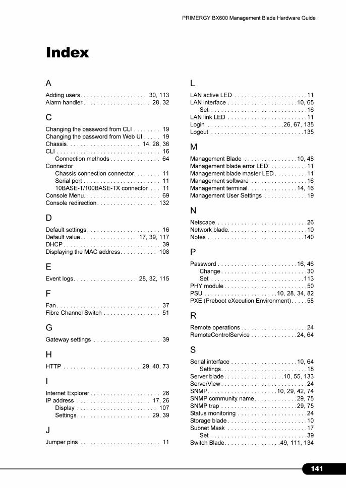
PRIMERGY BX600 Management Blade Hardware Guide
Index
A
Adding users. . . . . . . . . . . . . . . . . . . . 30, 113
Alarm handler . . . . . . . . . . . . . . . . . . . . 28, 32
C
Changing the password from CLI . . . . . . . . 19
Changing the password from Web UI . . . . . 19
Chassis. . . . . . . . . . . . . . . . . . . . . . 14, 28, 36
CLI . . . . . . . . . . . . . . . . . . . . . . . . . . . . . . . 16
Connection methods . . . . . . . . . . . . . . . 64
Connector
Chassis connection connector. . . . . . . . 11
Serial port . . . . . . . . . . . . . . . . . . . . . . . 11
10BASE-T/100BASE-TX connector . . . 11
Console Menu. . . . . . . . . . . . . . . . . . . . . . . 69
Console redirection . . . . . . . . . . . . . . . . . . 132
D
Default settings . . . . . . . . . . . . . . . . . . . . . . 16
Default value. . . . . . . . . . . . . . . . . 17, 39, 117
DHCP . . . . . . . . . . . . . . . . . . . . . . . . . . . . . 39
Displaying the MAC address. . . . . . . . . . . 108
E
Event logs. . . . . . . . . . . . . . . . . . . 28, 32, 115
F
Fan . . . . . . . . . . . . . . . . . . . . . . . . . . . . . . . 37
Fibre Channel Switch . . . . . . . . . . . . . . . . . 51
G
Gateway settings . . . . . . . . . . . . . . . . . . . . 39
H
HTTP . . . . . . . . . . . . . . . . . . . . . . . 29, 40, 73
I
Internet Explorer . . . . . . . . . . . . . . . . . . . . . 26
IP address . . . . . . . . . . . . . . . . . . . . . . 17, 26
Display . . . . . . . . . . . . . . . . . . . . . . . . 107
Settings. . . . . . . . . . . . . . . . . . . . . . 29, 39
J
Jumper pins . . . . . . . . . . . . . . . . . . . . . . . . 11
L
LAN active LED . . . . . . . . . . . . . . . . . . . . . .11
LAN interface . . . . . . . . . . . . . . . . . . . . .10, 65
Set . . . . . . . . . . . . . . . . . . . . . . . . . . . . .16
LAN link LED . . . . . . . . . . . . . . . . . . . . . . . .11
Login . . . . . . . . . . . . . . . . . . . . . . .26, 67, 135
Logout . . . . . . . . . . . . . . . . . . . . . . . . . . . .135
M
Management Blade . . . . . . . . . . . . . . . .10, 48
Management blade error LED. . . . . . . . . . . .11
Management blade master LED . . . . . . . . . .11
Management software . . . . . . . . . . . . . . . . .16
Management terminal . . . . . . . . . . . . . . .14, 16
Management User Settings . . . . . . . . . . . . .19
N
Netscape . . . . . . . . . . . . . . . . . . . . . . . . . . .26
Network blade. . . . . . . . . . . . . . . . . . . . . . . .10
Notes . . . . . . . . . . . . . . . . . . . . . . . . . . . . .140
P
Password . . . . . . . . . . . . . . . . . . . . . . . .16, 46
Change . . . . . . . . . . . . . . . . . . . . . . . . . .30
Set . . . . . . . . . . . . . . . . . . . . . . . . . . . .113
PHY module . . . . . . . . . . . . . . . . . . . . . . . . .50
PSU . . . . . . . . . . . . . . . . . . . . . .10, 28, 34, 82
PXE (Preboot eXecution Environment) . . . . .58
R
Remote operations . . . . . . . . . . . . . . . . . . . .24
RemoteControlService . . . . . . . . . . . . . .24, 64
S
Serial interface . . . . . . . . . . . . . . . . . . . .10, 64
Settings. . . . . . . . . . . . . . . . . . . . . . . . . .18
Server blade . . . . . . . . . . . . . . . . . .10, 55, 133
ServerView . . . . . . . . . . . . . . . . . . . . . . . . . .24
SNMP. . . . . . . . . . . . . . . . . . . . .10, 29, 42, 74
SNMP community name. . . . . . . . . . . . .29, 75
SNMP trap . . . . . . . . . . . . . . . . . . . . . . .29, 75
Status monitoring . . . . . . . . . . . . . . . . . . . . .24
Storage blade . . . . . . . . . . . . . . . . . . . . . . . .10
Subnet Mask . . . . . . . . . . . . . . . . . . . . . . . .17
Set . . . . . . . . . . . . . . . . . . . . . . . . . . . . .39
Switch Blade. . . . . . . . . . . . . . . . .49, 111, 134
141

1
System fan unit . . . . . . . . . . . . . 10, 28, 36, 82
T
Telnet . . . . . . . . . . . . . . . . . . . . . . . . . . . . . . 64
Set . . . . . . . . . . . . . . . . . . . . . . . 29, 40, 76
U
User name . . . . . . . . . . . . . . . . . . . . . . . 16, 46
W
Web UI. . . . . . . . . . . . . . . . . . . . . . . . . . 16, 26
42

• The contents may be revised without prior notice.
• Fujitsu assumes no liability for damages to third party copyrights or other rights
arising from the use of any information in this manual.
• No part of this manual may be reproduced in any form without the prior written
permission of Fujitsu.
PRIMERGY BX600 Management Blade
Hardware Guide
B7FH-5611-01ENZ0-00
Issued in
Issued by
August, 2008
FUJITSU LIMITED