PRESSURE GROUTING, FINE FISSUR - apps.dtic.mil · This investigation of various grout mixtures and...
83
PRESSURE GROUTING, FINE FISSUR.ES N4 11) M TECHNICAL REPORT NO. 6-437 October 1956 Waterways experiment Station CORPS OF ENGINEERS, U. S. ARMY Vickcsburg, Mss 55 .pp;
Transcript of PRESSURE GROUTING, FINE FISSUR - apps.dtic.mil · This investigation of various grout mixtures and...
PRESSURE GROUTING, FINE FISSUR.ES
N411)
M
TECHNICAL REPORT NO. 6-437
October 1956
Waterways experiment StationCORPS OF ENGINEERS, U. S. ARMY
Vickcsburg, Mss5 5.pp;
THIE CWiTENTS OF IHIS REPORT ARE NOT TO BE USED
I-OR ADVERTISING, PUBLICATION, OR PRGNOTIONAL
PURPOSES
1922
~v
PREFACE
The work reported herein was authorized by the Office, Chief of
Engineers) as part of Item CW 612, "Prepakt Concrete and Grouting," of
the Corps of Engineers Civil Works Investigations program, and completed
under Item CW 550, "Grouting Research - Concrete Dam Frundations."
The investigation was begun in 1949 and was conducted by the Coll-
crete Division of the Waterways Experiment Station under the supervision
of Mr. V. -. Minear, formerly of the Office, Chief of Engineers, and
Mr. H. K. Cook, formerly Chief of the Concrete Division. Personnel of
the Waterways Experiment Station actively engaged in Lhe work were
T. B. Kennedy, C. H. Willetts, W. 0. Crawley, R. L. Curry, B. Mather,
K. Mather, and L. Pepper. This report was prepared by Mr. Cook and
Mr. Kennedy.
j
_~
vii
CONTENTS
Page
PREFACE . . . . . . . . . . . . . . . . . . . . . . . . . v
SLMAARY . . . . . . . . . . . . . . . . . . . . . . . .. . . ix
PART I: INTODUCTION ........................... .. 1
Purpose of Investigation ....... ................. 1Description of Investigation ... ............... . .. 1
PART II: MATERIALS, E)UWiMENT, AND SPECIMENS .......... 4
Materials ......... ........................ . . 4G- uting Equipment .................... 7Specimens . . . . . . . . . . . . . . . . . . . . . . . 9
PART iII: GROUT PUMPING TESTS ......... . . . . . . . . . 11
Gneral Procedures . ............ . . . . . . . . 11Discussion of Pumping Tests . . . . . . .......... 12
PART IV: TESTS OF GROUT CHARACTERISTICS ... .............. . 29
Consistency . . . . . . . . . . . . . . . . ... . . . . . . 29Bleeding . . .................. . . . . . . 31Setting Time . . . . . . . . . . . . . . . . . . .. . . . . 33Solubility . . . . . . . . . . . . . . . . . . . . . . . . 34
Conclusions . . . . . . . . . . . . . . . . . . . . . . . . 35
FART V: SUNMARY OF RESU LTS ................... 37
Factors Influencing Penetration of Grouts . . . . . . .. 37Factors Affecting Quality of Grout Films ......... 39Measurement of Consistency . . . . . . . . . . . . . . . . 41
PART VI: CONCLUSIONS ..................... . . 43
TABLES i-4
APPENDIX A: TESTS ON SIMULATED GROUTS AND EXAMINATION OFMATERIAL FILLING FISSURE IN TEST 9, STAGE 1 . . . . Al
Test Conditions . . . . . . . . . . . . . . . . . . . .. AlTime of Set . . . . . . . . . . . . . . . . . . . . . . . . A12
Bleeding . . . . . . . . . . . . . . . . . . . . . . . .. A4Petrographic Examination of Specimens of GrovtMixture 3A at 13 Days ... D.y. . .. . A5
Reoifts of Fyamination of Bled W;ter and Paste . . . ... A6Results of' Examination of' Thin Sections . ......... . A7Petrographic Examination of Grout Filling Fissure
in Test 9 . . . . . . . . . . . . ........ .A8
Chemical Tests on Simulated Grout Mixture 3A . . . . ... A1OChemical Examination of Sludge from Fissure of Test 9 . . . A12
TABLE Al
- -- ------ -
viii
C$)NTE2T'3 (Continued)
Page
APPENDIX B: CONSIDERATIONS INVOLVED IN STRENGTH AND PORW -ITY
OF HIGH RATIO WATER-CENENT GROUTS . . . . . . . . . B).
Net Water Content and Porosity of the Cement Paste B4..
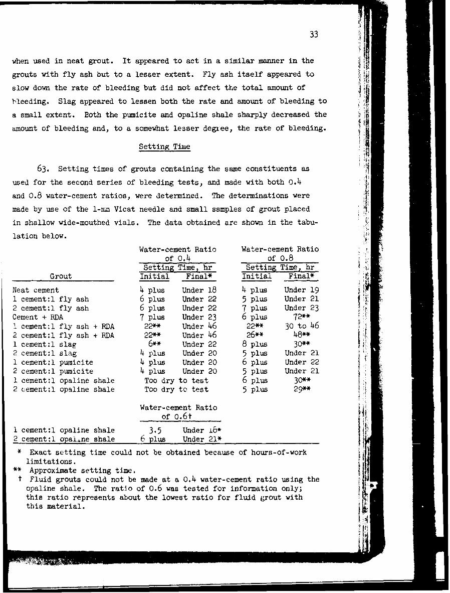
ix
SUMMARY
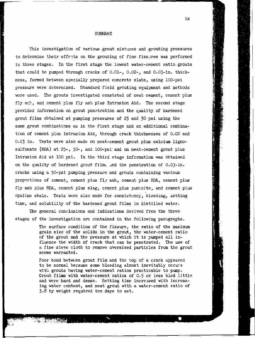
This investigation of various grout mixtures and grouting pressures
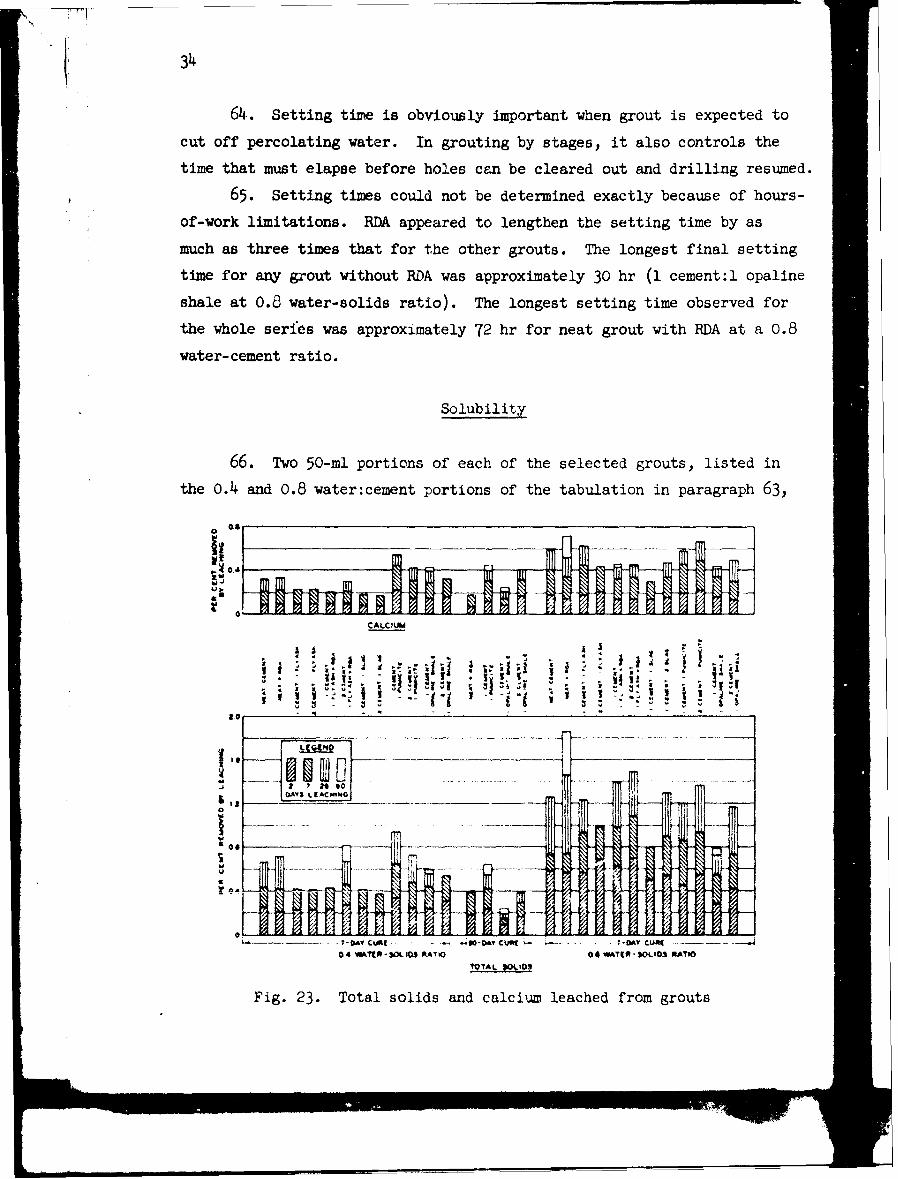
to determine their effects on the grouting of fine fissares was performed
in three stages. In the first stage the lowest water-cement ratio grouts
that could be pumped through cracks of 0.01-, 0.02-, and 0.03-in. thick-
ness, formed between specially prepared concrete slabs, using 100-psi
pressure were determined. Standard field grouting equipment and methods
were used. The grouts investigated consisted of neat cement, cement plus
fly ash, and cement plus fly ash plus Intrusion Aid. The second stage
provided information on grout penetration and the quality of hardened
grout films obtained at pumping pressures of 25 and 50 psi using the
same grout combinations as in the first stage and an additional combina-
tion of cement plus Intrusion Aid, through crack thicknesses of 0.02 and
0.03 in. Tests were also made on neat-cement grout plus calcium ligno-
sulfonate (RDA) at 25-, 50-, and 100-psi and on neat-cement grout plus
Intrusion Aid at 100 psi. In the third stage information was obtained
on the quality of hardened grout film. and the penetration of 0.03-in.
cracks using a 50-psi pumping pressure and grouts containing various
proportions of cement, cement plus flY ash, cement plus RDA, cement plus
fly ash plus RDA, cement plus slag, cement plus pumicite, and cement plus
opaline shale. Tests were also made for consistency, bleeding, setting
time, and solubility of the hardened grout films in distilled water.
The general conclusions and indications derived from the three
stages of the investigation are contained in the following paragraphs.
The surface condition of the fissure, the ratio of the maximumgrain size of the solids in the grout, the water-cement ratioof the grout and the pressure at which it is pumped all in-fluence the width of crack that can be penetrated. The use ofa fine sieve cloth to remove oversized particles from the groutseems warranted.
Poor bond between grout film and the top of a crack appearedto be normal because some bleeding almost inevitably occurswith grouts having water-cement ratios practicable to pump.Grout films with water-cement ratios of 0.5 or less bled littleand were hard and dense. Setting time increased with increas-ing water content, and neat grout with a water-cement ratio of3.8 by weight required ten days to set.

x
The use of fluidifiers allowed some reduction in water-cementratio that could be forced into a given crack thickness. Theiruse increased setting time, decreased bleeding, and had littleeffect on the solubility of the groat film as judged by leach-ing tests.
An approximately straight-line drop in pressure occurred fromthe intake to the exhaust end of the crack when cracks of 0.02-and 0.03-in. thickness were grouted. With finer fissures thepressure drop was steeper for the first 12 in. than for theremaining 36 in. of crack length.
Frequently the solids appeared to have agglomerated in hardenedgrout films containing fly ash. The use of ground, water-quenched blast-furnace slag, pumicite, and opaline shale ap-peared to reduce bleeding and improve the appearance ofhardened grout films.
Resistance of grout films to leaching increased with age andwith decreasing water-cement ratio. Ground slag and opalineshale reduced the solubility of grout. The effects of pumiciteand fly ash on solubility were inconclusive.
-ME
PRESSURE GROUTING FINE FISSURES
PART I: INTRODUCTION
Purpose of Investigation
1. It is recognized that the strength and 4mpermeability of a
grout film follow the water-cement ratio law as do mixtures of other ma-
terials containing water and cement. Because of this fact it is desir-
able, where important work is concerned, to use grouts containing as low
water contents per unit volume as possible. Since the lower the water
content the thicker the grout, it is also important to determine the
thickest consistencies that will penetrate cracks of' various widths at
given pressures.
2. In sealing fine seams, grouts having water contents as high as
20 to 1 (20 cu ft of water per bag of cement) are sometimes used, and
grouts of a consistency as thin as 10 to 1 are not uncommon. The assump-
tion has been that thin grout placed under sufficient pressure to force
out the excess water used to obtain such a consistency will form a hard
durable film. Whether it is always possible to exert enough pressure to
squeeze out this excess water is questionable, and for this reason I
knowledge of the physical nature f the grout films produced by fairly
high water-cement ratios would be valuable. Such grouts are believed to
be extremely pervious and, in time, susceptible to leaching that will
transform an impervious area into a pervious one.
3. The purpose of the program was to obtain information on the
degree to which the penetration of fine fissures by grout was influenced
by surface texture of specimen, pumping pressure, water-cement ratio,
chemical fluidifiers, and finely divided mineral additives. It was also
desired to determine the effect of these factors on the quality of the
hardened grout films.
Description of Investigation
4. Preliminary tests were conducted to develop the best technique
2
for the grouting tests. It was found -t the most practical approach
to use in penetrating fine cracks is that used in the field wherein a
very dilute grout is used first and is gradually thickened by addition
of solid materials until refusal results. This procedure was adopted
and enabled the operators to determine the stiffest grout, of any type
tested, that could be pumped through the three fissure thicknesses se-
lected for investigation at pressures up to 100 psi.
5. The study was conducted in three separate stages. The scope
of each stage was as follows:
a. The first stage furnished data on the lowest water-cementratios of grouts that could be pumped thrcugh fissures of0.01-, 0.02-, and 0.03-in. thickness at 100-psi pressure,using standard field equipment and methods, under thefollowing grout conditions: (1) neat cement; (2) cementplus fly ash; (3) cement plus fly ash plus Intrusion Aid.A study of consistency, bleeding characteristics, andsetting times of the various grouts was also made. Afterthe grouting tests were completed, chemical and petrographicexaminations of bleed water and solid residues from some ofthe high water-cement ratio grouts, and further bleedingtests were made. Results of these supplemental tests arecontained in appendix A.
b. The second stage provided data on grout penetration obtainedat pumping pressures of 25 and 50 psi using the three groutcorditions of the first stage and the additional conditionof cement plus Intrusion Aid. Tests were also made of neat-cement grout plus calcium lignosulfonate (FDA) at 25, 50,and lo0 psi, ard of neat-cement grout plus Intrusion Aidat 100 psi.
c. The third stage consisted of: pumping tests through a 0.03-in.-thick crack at 50 psi using the seven grout conditionslisted below; tests of the grouts themselves for consistency,bleeding, setting time; and tests to determine the apparentquality of hardened grout films and their solubility in dis-tilled water under various leaching conditions.
Grout Conditions
(1) Neat cement (5) Cement plus slag(2) Cement plus fly ash (6) Cement plus pumicite(3) Cement plus RDA (7 Cement plus opaline shale(4) Cement plus fly ash
plus RDA
F1me of the above materials were used in various propor-ions of one to thu other so that a total of 17 different
3
grout mixtures were pumped. These are described in detaillater in the report. Stage three also included detailedtests of consistency, bleeding, and setting time of thefluid grouts, and leaching tests made with distilled wateron the hardened grouts as well as examinations of thehardened grout films for apparent quality. These bleedingtests and the examination of the hardened grout films werein addition to the work described in appendix A and donein the first stage of the investigation.
6. This report contains the essential information obtained in the
three stages. This information has been grouped so that all data bearing
on one condition are presented together rather than discussed under the
separate stages.
i
PART II: MATERIAIS, EQUIPMENT, AND SPECIMENS
Materials
Cement
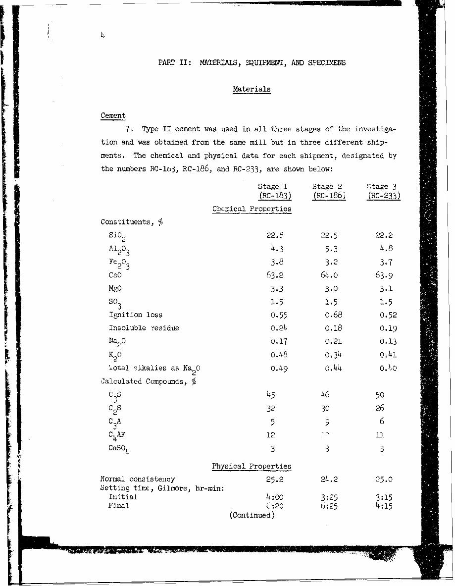
7. Type II cement was used in all three stages of the investiga-
tion and was obtained from the same mill but in three different ship-
ments. The chemical and physical data for each shipment, designated by
the numbers RC-Io3, RC-186, and RC-233, are shown below:
Stage 1 Stage 2 Ftage 3(RC-183) (RC-186) (RC-233)
Chemical Properties
Constituents, %SiO2 22.8 22.5 22.2
Al203 4.3 5.3 4.8
Fc203 3.8 3.2 3.7
CaO 63.2 64.o 63.9
MgO 3.3 3.0 3.1
so3 1.5 1.5 1.5
Ignition loss 0.55 0.68 0.52
Insoluble residue 0.24 0.18 0.19
NaO 0.17 0.21 0.13
K,0 0.48 o.34 n.41
ota. ritkalies as Na2 0 o.49 ;.44 0.4Calculated Compounds, %
c 3s 45 C, 50
C 2S 32 3C 26
C 3A 5 9 6
C4AF 12 13l
CaSO 4 3 3 3
. Physical Properties
Normal consistency 25.2 24.2 25.0Setting time, Gilmore, hr-min:
Initial 4:00 3 : 25 3:15Final , :20 b:25 4:15
(Continued)
Stage 1 Stage 2 Stage 3(EC-183) _Lc,L6) (RC-233)
Physical Properties (continued)
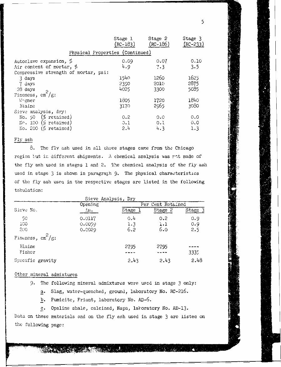
Autoclave expansion, % 0.09 0.07 0.10Air content of mortar, % 4.9 7.3 3.5Ccmipressive strength of mortflar, psi:3 days 1540 1260 1 62c3-7 days 2390O 2010 2875
28 days 2 4025 3300 5085Fineness, cm /.
v' un e r 1805 1720 184oBlaine 3170 2965 3080
Sieve- anaiysis, dry:No. 50 (%retained) 0.2 0. o 0.0NP. 100 (, k, retained) 0. .1 0.0No. 200 ~Sretained) 2.4 4.3 1.3
Fly ash
8. The fly ash used in all three stages came from the Chicago
region bu-t i:- diffearent shipments. A chemical analysis -Vas r-It made of
the fly ash used in stages 1 and 2. The chemical analysis of the fly ash
used in stage 3 is show.n in paragralph 9. The physical characteristics
of the fly ash usea in the respective stares are listed in the following
tabulation:
SieveAnalysis,_Dry _________
Opening Per Cent RetainedSieve No. u.Stage 1 Stage 2 Stage3
500.0117 0.4 0.2 0.9100 5 1.3 1. 1 0.9
0.0029 6.2 6.o 2.52
Fintness, cmr gBlaine 2795 2795 - -- -
Fisher ------ -- 3335
Specific gravity 2.43 2.43 2.48
Other mineral admixtures
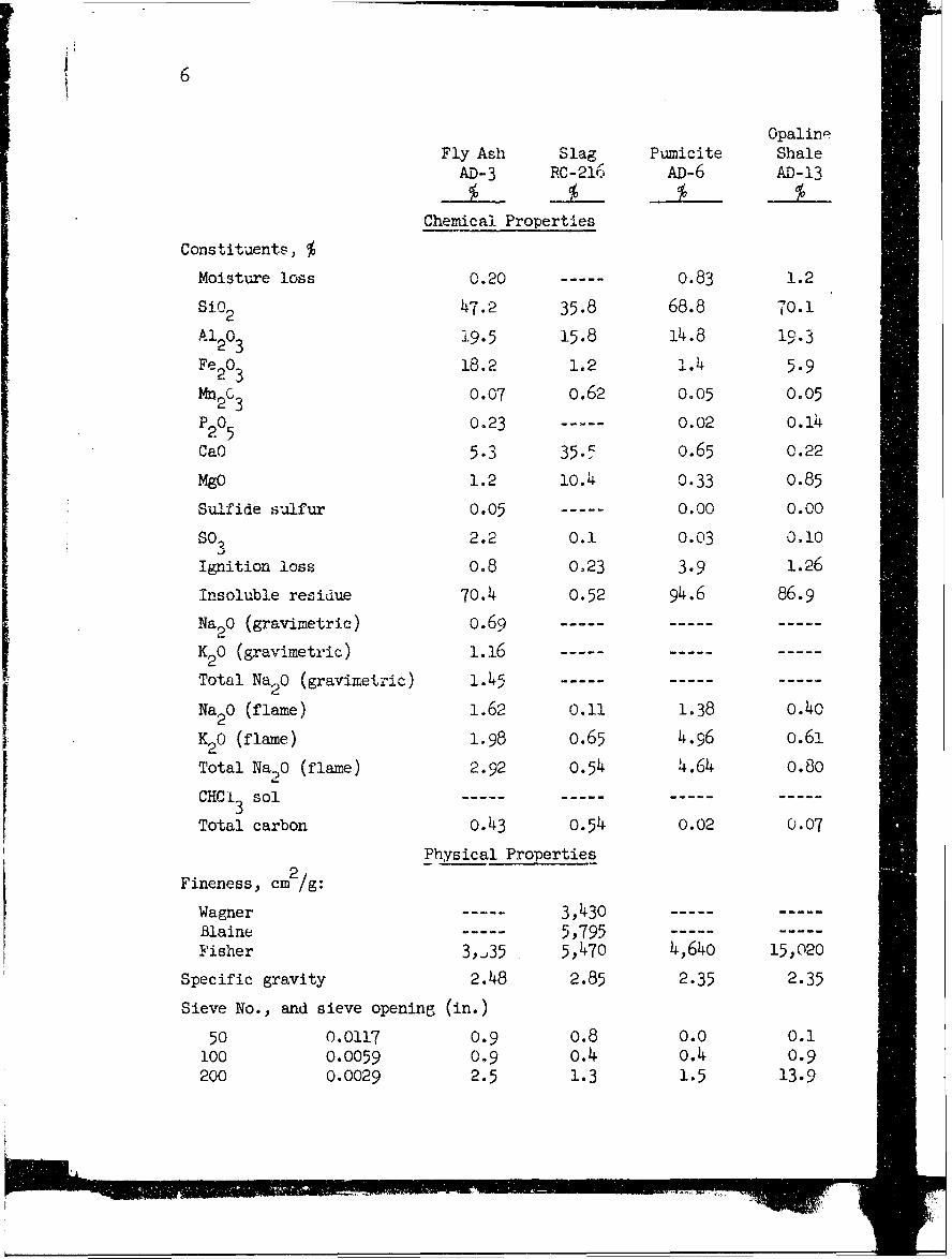
9. The following mineral admixtures were uscd in stage 3 only:
a. Slag, water-quenched, ground, laboratory No. RC-.216.
b. Pumicite, Friant, laboratory No. AD-6.
c. Opaline shale, calcined, Napa, laboratory No. AD-13.
Data on these materials and on the fly ash used in stage 3 are iistea onthe following page:,
6
OpalineFly Ash Slag Pumicite ShaleAD-3 RC-216 AD-6 AD-13
Chemical Properties
Constituents, %
Moisture loss 0.20 0.83 1.2
S102 47.2 35.8 68.8 70.1
Al203 19.5 15.8 14.8 19.3
Fe20 3 18.2 1.2 I. 4 5.9Mn2C3 0.07 o.62 0.05 0.05
P205 0.23 0.02 o.14
CaO 5.3 35. o.65 0.22
MgO 1.2 1O.4 0.33 0.85
Sulfide silfur 0.05 0.00 0.00
s03 2.2 0.1 0.03 0.10
Ignition loss 0.8 0.23 3.9 1.26
Insoluble residue 70.4 0.52 94.6 86.9
Na2 0 (gravimetric) 0.69 .....
K20 (gravimetric) 1.16
Total Na2 0 (gravimetric) 1.45 .....
Na2 0 (flame) 1.62 0.11 1.38 0.40
K 20 (flame) 1.98 o.65 4.96 0.61
Total Na20 (flame) 2.92 O.54 4.64 0.80
CHCI3 sol
Total carbon o.43 O.54 0.02 0.07
Physical Properties
Fineness, cm 2/g:
Wagner 3,430Blaine .... 5,795Fisher 3,,35 5,470 4,64o 15,020
Specific gravity 2.48 2.85 2.35 2.35
Sieve No., and sieve opening (in.)
50 0.0117 0.9 o.8 0.0 0.1100 0.0059 0.9 0.4 o.4 0.9200 0.0029 2.5 1.3 1.5 13.9
7
Chemical admixtures
10. Intrusion Aid from the same shipment was used in stages I and
2 of the program and was furnished by the Prepakt Concrete Company,
Cleveland, Ohio. It causes slight expansion of the grout and is pur-
ported to prevent agglomeration of the sulids and aid intrusion of the
grout.
11. Calcium lignosulfonate, RDA, was used in stages 2 and 3 and
was furnished by Dewey and Almy Chemical Company, Cambridge, Mass.
Marasperse C was used in stage 2 only and was furnished by the Marathon
Corporation, Rothschild, Wis. These materials were added for the same
ptuposes as the Intrusion Aid, except that they do not have the expansion
characteristics of the Intrusion Aid.
Grouting Equipment
12. The grout pump wa.. a single-cylinder, reciprocating 3-3/4- by
2-1/2.. by 5-in. steam pump with rubber piston and valves, air-driven for
these tests. The grout mixer was a paddle-type machine powered by a motor
from an electric drill. A photograph of the grouting assembly, including
a typical specimen, as used in stage 1 of the program is shown on fig. 1.
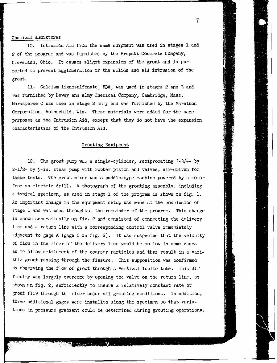
An important change in the equipment setup was made at the conclusion of
stage 1 and was used throughout the remainder of the program. This change
is shown schematically on fig. 2 and consisted of connecting the delivery
line and a return line with a corresponding control valve immediately
adjacent to gage A (gage 0 on fig. 2). It was suspected that the velocity
of flow in the riser of the delivery line would be so low in some cases
as tn allow settlement of the coarser particles and thus result in a vari-
able grout passing through the fissure. This supposition was confirmed
by observing the flow of grout through a vertical lucite tube. This dif-
ficulty was largely overcome by opening the valve on the return line, as
shown on fig. 2, sufficiently to insure a relatively constant rate of
grout flow through t riser under all grouting conditions. In addition,
three additional gages were installed along the specimen so that varia-
tions in pressure gradient could be determined during grouting operations.

GAGE4 rGGE 3 GAGE2 GAE I AGE
PRESPESSQR COINE A
Fig. 2. Equiet diegra (ot stog scage)ofn rti
G AG~m E n 4 e u fo t eGt s tA e 2 G An d I3A E 0 V L E
L'

9
Specimens
13. It had originally been intended to cast prisms of high-strength
concrete 6 in. wide by 7 in. deep by 52 in. long over-all, containing two
3/4-in. pipe nipples 48 in. apart embedded in the same side along the
center line, with the axis of the nipple normal to the side surface and
extending to a point just past the center of the prism. After curing
for approximately seven days, the prisms were to be sawed from end to end,
producing two pieces approximately 3 in. thick by 7 in. wide by 52 in.
long with the saw cutting off the tip ends of the embedded pipe nipples.
Thun i/2-in.-wide shimstock of the desired thickness was to have been
placed between the two halves of the prism to serve as separator gaskets
around the edges and ends and the halves fitted back together and held
in place with C-clamps, thus forming a fissure 6 in. wide by 48 in. longbetween pipes. It was then planned to pump the grout into the pipe nipple
at one end and out the pipe nipple at the other end.
14. This scheme did not prove successful because it was found im-
possible to make a perfectly straight cut with the diamond saw. Further-
Lore, the kerf of the saw was quite pronounced leaving a series of ridges
and grooves which made a tight seal and control of the crack thickness
impossible. Consequentiy, the specimens were cast in two pieces using a
sheet of 1/4-in. plate glass as a separator in the plane where the saw
cut would have been made. Several pieces of glass were measured for
variation in thickness and none were found to vary over 0.002 in. Sur-
faces cast against the glass were smooth and true. The specimens for
stage 2 and 3 were cast with five 3/4-in. pipe nipples, spaced 12 in.
apart, along the center line of one slab to accommodate pressure gages
and to allow flow of the grout. The specimens for stage 1 contained only
two pipe nipples. The specimens were pumped in a horizontal position
for the following reasons:
a. The most dangerous conditions in grouting under a damare caused by extensive open passages such as horizontalbedding planes. It was desired to learn something aboutgrout flow and pressure distribution under such conditions.
b. It was hoped to learn something concerning the validity ol
10
the assumption that excess mixing water can be forced outof the grout by the application of pressure. It was be-lieved that if this did occur a good bond would be madewith the top as well as the bottom half of the specimen;if not, bleed water would prevent bond with the top half.
PART III: GROUT PU ING TESTS
General Procedures
Treatment of grout
15. Dry materials were all sieved through a 30-mesh sieve and the
mixed grout was passed through a 30-, 50-, or 100-mesh sieve depending
upon the water-cement ratio. The thinnest grouts were passed through a
100-mesh sieve, thicker grouts through a 50-mesh sieve, and the thickest
grouts through a 30-mesh sieve.
Grout injection
16. Grout injection was started by pumping water through the spec-
imen followed by a thin grout which was gradually thickened by the addi-
tion of solids. The desiied pressure was maintained on the specimen by
operating the bypass valve so that only a controlled portion of the total
flow of grout was shunted through the specimen. The pump was operated
at a speed of approximately 72 strokes per minute for the major portion
of the tests. At the lowest water-cement ratio for a given test more
than one hour of pumping was usually required to discharge one cubic foot
of grout through the fissure of a specimen. Grout flow stopped at any
given pressure when the grout became ,o," thick. In the stage 1 opera-
tions, pressure was maintained on specimens for 10 to 15 min after all
flow had stopped with the valve at B (fig. 1) open at all times. Water
continued to drip very slowly from the discharge line during final ap-
plication of pressure, being squeezed out after separating from the grout
film in the specimen. When gage B assembly was removed the short pipe
nipple cast in the test specimen was invariably found to be full of
hardened grout into which a pencil could only be forced with difficulty.
This was the case regardless of the consistency of the grout being pumped
at the end of the test. In stage 2 operations the valves at the entrance
and discharge ends of the specimen were closed as soon as all flow had
stopped and the pressure within the specimen was allowed to equalize in-
sofar as internal conditions would permit. Pumping for stage 3 was in
most instances conducted as in stage 1 although for some tests tb valves
were closed on both ends of the specimens as in stage 2.
'7V"
12
Test conditions
17. The major portion of the tests on the various grout mixyures
was performed at pressures of 100, 50, and 25 psi; the grouts were pumped
through cracks of O.O1-, 0.02-, and 0.03-in. thickness. Some of the
tests, particularly those in stage 3 where the effects of the addition
of several finely divided materials were investigated, w-re conducted
only at a pumping pressure of 50 psi. The test conditions and the com-
position of the grout mixtures investigated in all three stages of the
program are shown in table 1.
18. Observations were made daxring and after pumping for:
a. The effect of specimen surface on the water-cement ratioand pumpability of the grout (stage 1 only).
b. Lowest water-cement ratio of grout that would penetratethe three different fissure thicknesses.
c. Pressure drop along the specimen.
d. Rate of grout flow at a given pressure, water-cementratio, and crack thickness.
e. Relationship between pumping pressure and lowest water-cement ratio grout that a fissure would take.
f. Relationship of particle size of grout solids to the widthof crack that could be grouted.
R. Effect of chemicals (Intrusion Aid and RDA) on the pene-tration qualities of grouts.
h. Quality of hardened grout films, from visual obscrv.tion.
i. Strength of grout film as judged by shear tests (forstage 2 only).
A. Special observations and tests were made in stage 3 forconsistency of the grout at each change in water-cementratio by measuring change in unit weight of the grout andthe torque imparted to a piano-wire consistency eter.
Discusson of Pumping Tests
19. Table 1 shows the major results of the pumping tests for all
combinations of materials tested. In most instances the lowest water-
cement ratio shown for a given grout mixture and test condition was the
lowest water-cement ritio that could be pumped. It is considered, however,

13
that the water-cement ratio at which the flow equals 0.1 cu ft per min
(6 cu ft per hr) is the stiffest grout practical for field pumping.
20. Throughout this report water-cement ratio has been expressed
by weight of water to cement or to cement plus other solids when mate-
1'ials such as fly ash were added to the grout.
Effect of surface texture of
specimen on grout penetration
21. Pumping tests 2 through 12 were made using specimen surfaces
from which the glaze, due to casting against the glass, was removed by
light rubbing with a carborundum stone. Tests 13 through the end of the
program were made using specimen surfaces from which the glaze had not
been removed. The effects of type of specimen surface, fineness (maxi-
mum grain size) of the grout, and crack thickness on the water-cement
ratio of the grout are shown on fig. 3 and discussed on the following
page:
5.0
LEGEND
40 . L NEAT GROUT, RUSOED SURFACE.
4 2. NEAT GROUT, SMOOTH SURFACE. -
3 CEMth"-FLY ASH GROUT, RUBOED SURFACE.
4 CEMENT-FLY ASH GROUT, SMOOTH SURFACE.
5 CEMENT-FLY ASH PUJS INTRUSION AID,-2 30 RUBBED SURFACE.
0 G. CEMENT-FLY ASH PLUM INTRUSION AID,SMIOOTH SURFACEL _
W20-_ _ _- -
I-
iti
hii
$1 7I 4 I 3 2 3 4 1 1
003-IN OP NIG 002 -IN. OPENING 0.01 " N OPCNIWG
Fig. 3. Effect of crack thickness and surface texture,and grout fineness on water-cement ratio
7777 -r
1' 14
a. The combination of smooth surfaces and grout strainedthrough a No. 50 sieve permitted the ube of lower water-cement ratios for the 0.03- and 0.02-in. fissures thanfor the combination of rubbed surfaces and grout strainedthrough a No. 30 sieve, for both neat grout and groutcontaining fly ash.
b. The combination of smooth surfaces and grout strainedthrough a No. 50 sieve permitted the passing of neat groutwith a water-cement ratio of 1.34 by weight through the
0.01-in. opening as contrasted with a water-cement ratioof 2.06 with the rubbed surfaces and neat grout strained
through a No. 30 sieve.
c. Grout conta'ning fly ash could not be pumped through the0.01-in. opening regardless of the type of surface orwhen strained through the No. 50 sieve even with a water-cement ratio of 4.30, the highest water-cement ratio used
in the tests. The reason for the poor pumpability of thefly ash grout is discussed in paragraph 22.
d. The use of Intrusion Aid permitted a slight reduction inwater-cement ratio when grouting the 0.03-in. fissureswith rubbed surfaces as compared to the grout containingfly ash and no Intrusion Aid, but did not help when grout-ing the 0.02- and 0.01-in. fissures with rubbed surfaces.
e. The use of Intrusion Aid permitted a slight reduction inwater-cement ratio when grouting the smooth-surfaced 0.02-and O.J3-in. fissures but was ineffective in promotingpenetration of the O.Ci-in. fissures.
22. The physical data on the materials used in stage 1 showed the
cement to have a greeter specific surface (Blaine 3172 cm per g, 97.3
per cent passing the No. 200 sievu) than the fly ash (Blaine 2795 ('m per
g, 92.1 per cent passing the No. 200 sieve), and showed that the fly ash
contained somewhat more than 0.4 per cent of material larger than 0.0117
in. (No. 50 sieve). This grain size exceeded the 0.01-in. opening of the
smallest fissre and caused a grid of oversi-e grains to build up quick-
ly during pumping which blocked the passage of the grout through the fis-
sure regardless of whether or not the grout contained Intrusion Aid.
Test 22 seemed to be an exception to the above but since a bad leak de-
veloped under the shim of this specimen during the test it ic believed
that the crack thickness was actually greater than 0.01 in., thus vitiat-
ing the results.
15
Influence of crack thick-ness on grout penetration
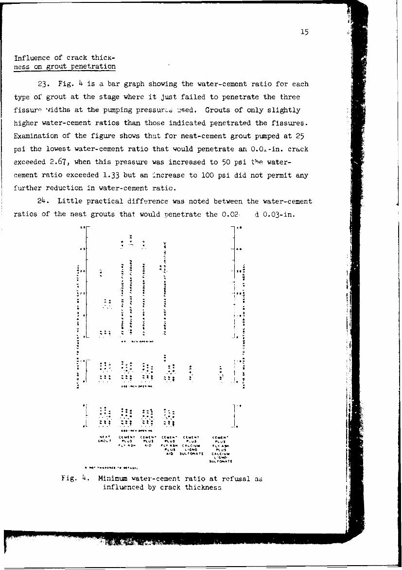
23. Fig. 4 is a bar graph showing the water-cement ratio for each
type of grout at the stage where it just failed to penetrate the three
fissure w idths at the pumping pressurco used. Grouts of only slightly
higher water-cement ratios than those indicated penetrated the fissures.
Examination of the figure shows that for neat-cement grout pumped at 25
psi the lowest water-cement ratio that would penetrate an O.O.-in. crack
exceeded 2.67, when this pressure was increased to 50 psi the water-
cement ratio exceeded 1.33 but an increase to 100 psi did not permit any
further reduction in water-cement ratio.
24. Little practical difference was noted between the water-cement
ratios of the neat grouts that would penetrate the 0.02- d 0.03-in.
6 0
t~~ 0
-
Z 4f z 2
C.0 T; V1- U 0. W I P 3 V 1, .
. . A Fv
, Q-4
Fig. 4. Minimum ater-cement ratio at refusal asinfluenced by crack thickness
II
iA
cracks. Plzniping pressure, within tte range investigated, also had little
efiect on the ability of grouts of various water-cement ratios to pene-
trate the 0.02- and 0.03-in. cracks.
25. Grouting of any of the 0.01-in. cracks with grouts containing
fly ash was found impracticable, regardless of the pressure applied, be-
cause of the maximin grain size of the fly ash.
26. The use of fly ash was of no benefit in grouting the 0.02-in.
crack, since it permitted no practical reduction in water-cement ratio
over neat grout. Pumping pressure, within the range used, was of little
value in improving the penetration of the 0.02-in. crack with a cement
and fly ash grout.
27. Grouts of cement and fly ash that would penetrate the 0.03-in.
crack were of slightly lower water-cement ratio than the neat grouts
that would penetrate cracks of similar width at 25 and 50 psi, but practi-
cally the same at 100 psi.
28. Use of Intrusion Aid in neat-cement grout permitted a sligh
reduction in water-cement ratio of the grouts that would penetrate both
the 0.02- and 0.03-in. cracks at the pressures tested.
29. RDA was used only at 50-psi pressure on the 0.02-in. crack
with neat cement and with cement plus fly ash; it appears to be as ef-
fective as Intrusion Aid with respect to grout penetration.
30. In the above discussion th2 effect of maximum grain size,
as indicated in paragraph 22, should be kept iii mind as well as the
fact that fig. 4 indicates water-cement ratios at refusal, whereas a
rate of flow of 6 cu ft per hr is the stiffebt grout practical for field
pumping.
Pressure drop along the specimen
31. The pressure gradient for the 0.02- and 0.03-in. cracks during
pumping was approximately a straight line with zero pressure at the exit
,,id of the specimen (gage 4), maximum pressure at the entrance end of
the specimen (gage 0), and intermediate pressures at gages 1, 2, and 3.
The static px.ssure, after pumping was stopped when the grout was thick
(water-cement ratio of less than 0.5) and valves at both entrance and
exit ends were closed, did not always equalize from end to end. This
i!L
m~ay have3 teen due to a thixotropic* condition developing in the thick
grout inirediately upon cessation of movement. and causing a 'blocking of
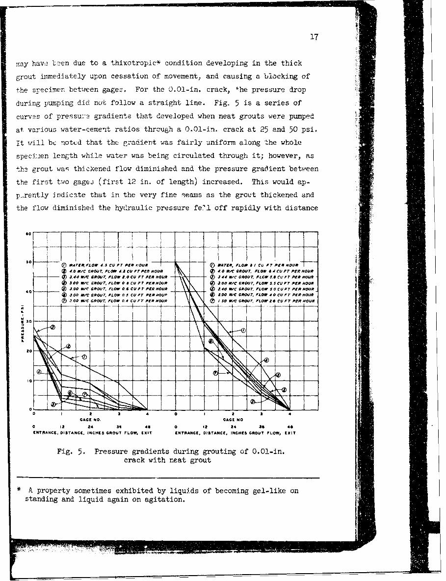
the s- 'ecirnen between gagez. For the 0.01-in, crack, '-he pressure drop
during pumping did not follow a straight line. Fig. 5 is a series of
curves of Pressu:r3 gradients that developed when neat grouts were pumped
at va-rious water-ceme'ft ratios thrculih a 0.0*1-in, crack at 25 and 50 psi.
it vil1 bt- nottd that the. pradient was fairly uniform along the whole
speci-aen length while water was being circulated through it; however, as
th2 grout waq thickened flow diminished and the pressure gradient betw~een
the first tCwo gage.3 (first 12 in. of length) increased. This would ap-
p-.rently indiceate that in the very fine reams as the grout thickened and
the flow diminished the hydIraulic pressure fe'?1 off rapidly with distance
so
wATEr.FEp io4. cu r r ogm 0ux D iwATrr, fLOll 8 Ci FT PER NOUR
0 OWIC GROU T, r L .c rU rT PEAt OUR (Vd RWCCOUT. LO .dCUO IRHUj.E 4ew'C GROU r Low z.0 vU FuTr PER mOUR ® 44av GROUT,nowsAc rPEyu-
®3,00 NyC CMRO4/Tn LO Oa cu FT PER HOUR ® .0 wvC GROUT, o . u;O' ofi® 3.0 Nc GROUT rLO 0o .6 scuFrT Pr mou.9 t 4o PvC GROUT. FLow s~ocoF PEr HrAOUR
40 ®w 3.0wc GROUT; nLow as5 CUFT PERmo tooP w~ *00 r, noROUoT; FLO rU PER HOUIR
3,00 WIC G.9U or L OW 0.4 c U ir PER HOUR 1®5 WZC GROUT, nLow* CU aFT r PER HOUR
i30 - - - ---
h20__ _ _1
10-4--N
0 a 3 0 1 3 4GAGE WO. GAGE No.
0 12 24 34 46 0 Qi 24 so 46ENTRANCE, DISTANCE, INCHES GROUT FLOW, EXIT ENTRANCE, DISTANCE. INCHES GROUT I LOW, EXIT
Fig. 5. Pressure gradients during grouting of 0.01-in.crack with neat grout
*A property sometimes exhibited by liquids of becoming gel-like onstanding and liquid again on agitation.
r77
,o, I I llI I I 1."' 1 ! I IAL ARESSURE DUARING PUMP/NG, *.. PRESSURE OURNC PUMPING
FLOW EQUALS 00 CU F7 FLOW EQUALS 60 CU FtPER HOUR PER HOUR
40 ~ ~ k 1/ PRSURT-*N 40W PRESSURE DURING PUMPING.
GROUT FLOW EQUALS 6.0 FLOW EQUALS 60 CU FT
CU FTPER HOUR PER HOUR!t 1 PRESSURE DURING PUMPING o..C_. PRESSURE OUING PUMPING
-- JUST PRIOR TO REFUSAL, ] JUST PRIOR TO REFUSAL,IL FLOW 0.9 CU FT PER HOUR L FLOW 3.6 CU Ft PER HOUR -
& T',4,j STATIC PRESSURE 10SSURE / MINAFTER REFUSAL- ArER REFUSAL
- I '":---I0-t
;zHz z'11IK I o0 I 2 3 4 5 6 0 1 2 3 4 5 6
GAGE GAGE
Fig. 6. Pressure gradient during PIE.g 7. Presisure gradient duringand after grouting 0.02-in. crack, and after grouting 0.0,-in. crack,
neat grout neat grout
, PRESSURE DURING PUMPING, W ,,.4, PRESSURE DURING PUMP/NG,FLOW EQUALS 60 CU FT FLOW EQUALS 6.0 cU FTPER HOUR I PER HOUR
40 *,-C.92, PRESSURE URING PUMPING-, 40 --- W/C 50 PRESSURE DURING PUMPING,FLOW EQUALS 6,0CU .F FLOW EQUALS 6.0 CUFTPER HOUR PER HOUR
-kC 57 PRESSURE "NG PUMPING -WIC 43 PRESSURE DURIN PUMPINGa ---- /ST PRIOR 1 REFUSAL, Io - AJUST PRIOR TO REFUSAL,
o30 t 7 CUFTPER HOUR--.----' 30 16 CU FT PER HOURWAC. Z STATIC PRESSURE /0 AMN ! W/C 40 STATIC PRESSURE /0 AlN
" , I - AFTER REFUSAL I I - AFTER REFUSAL
0I I
0 I 2 3 4 5 6 0 2 3 4 5 6GAGE GAGE
Fig. 8. Pressure gradient during Fig. 9. Pressure gradient duringand after grouting 0.02-in. crack, and after grouting 0.03-in. crack,
1 cement:1 fly ash grout 1 cement:1 fly ash grout
WKC .57 PRESSURE DURING PUMPING - W.AC.38 PRESSURE DURING PUMPING,SATFLOW Or 6.0 CUFT PER FLOW EQUALS 6.0 CU FTHOUR * * PER HOUR
40 - PRESSURE DURING PUMPING - 40 -- iC.46 PRESSURE DURING PUMPING,AT FLOW OF 6.0 CU FT PER -- FLOW EQUALS 6 0 CU FT
" __ HOUR PER HOUR
0- --- -0 PRESSURE DURING PUMPING t- ,,C P PRESSURE DURING PUMPINGJUST PRIOR TO REFUSAL ., , JUSt PRIOR TO REFUSAL.
30 -- 3 0 FLOWZ.3 CU FT PER HOUR,, "I,, 0 STATIC PRESSURE /0 ,,IN
, -- AFTER REFUSAL
.=o- .-, .. ,- . - ----10--- --- ' - -- "\-- - \ - - -ILI
0 1 2 3 4 5 6 0 1 2 3 4 5 6GAGE GAGE
Fig. 10. Pressure gradient during Fig. 11. Pressure gradient duriuggrouting 0.02-in, crack, neat grout and after grouting 0.03-in. crack,
+ Intrusion Aid (1%) neat cement + Intrusion Aid grout
L __h

19
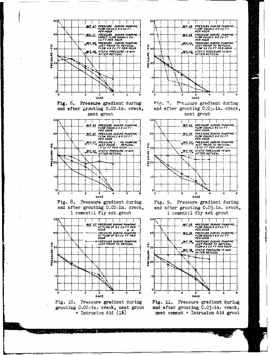
from the intrusion point. Conditions of pressure gradient and static
presbure after pumping are shown on figs. 6-14 for crack thicknesses of
0.02 and 0.03 in.
32. These figures show that in cracks with smooth walls and thick-
nesses of 0.02 in. or more the conditions of flow ,nd pressure are simi-
lar to those of water. Irregularities in the curves are due to faulty
operation of the ga&,j occasioned Ly plugging. Water-cement ratio values
at which the grouts vould act like water, relative to pressure distribu-
tion, might be different in nature where fissure walls are rough.
30- -- -
SW/C t.0 FLOW 8.3 CU FT PER HOUR
It-
oN- 1 .10 I 2 3 4 5 6
GAGE
Fig. 12. Prssure gradient duringgrouting 0.02-in. crack, 1 cement:
1 fly ash + Intrusion Aid grout
-10
-- z .49 PRESSURE DURING PUMPING, FLOW - WIC.40 PRESSURE DURING PUMPING. FLOW0 EQUALS 6.0 CU FT PER lhOUR i EQUALS 6.0 CU FT PER HOUR40--sTA TIC PRESSURE 10 MI/N AF TER - 0 - lqjPRESSURE DURING PUMPINGFLW
4R EUS AL- E-UA1-4 LS00CUF
r PER HO UR -
J_
2 1 I
,o[ I j * '
W to
0 i 0 !0 1 2 3 4 5 0 1 3 4 5 6
GAGE GAGE
Fig. 13. Pressure gradient during Fig. 14 . Pressure gradient duringgrouting 0.03-in. crack, 1 cement: and after grouting 0.02-in. crack1 fly ash + Intrusion Aid grout 1 cement:l fly ash + Intrusion Aid
grout
20
Rate of flow at givenpressure, water-cementratio and crack thickness
33. Fig. 15 is a bar graph showing the amount (in cubic feet per
hour) of various grouts, all with a water-cement ratio of 0.5, that could
be pumped through 0.02- and O.C,'-in. cracks at the three pumping pres-
6ures employed. Fig. 16 presents the same data in curves, omitting the
data on the 1 cement:l fly ash plus Intrusion Aid grout, which are anom-
alous and inconclusive.
34. Increasing pressure caused proportionately increasing flow.
Apparently the flow of the 1 cement:l fly ash grout was greater at equiva-
lent pressures and crack openings than that of neat grout.
35. The use of Intrusion Aid in the neat grout increased flow at
equivalent pressures and crack thicknesses over plain neat grout and
caused greater flow than did the use of fly ash. Data on the effect of
Intrusion Aid on the 1 cement:l fly ash grout were inconclusive.
36. The rate of flow provides a realistic measure of the viscosity
of a grout. Figs. 15 and 16 show that the rate at which a grout can be
injected into a crack is influenced by pressure and composition. Rate
of flow is an index to the distance a grout can be pushed at a given
pressure before friction causes the flow to cease. Under conditions
dictating the use of low-pressure grouting, greater density of drilling
than ordinary or the use of fluidifiers is indicated.
Relationship between pump-ing pressure, water-cementratio, ead crack thickness
37. An examination of fig. 4 shows that the crack thickness had a
great effect on the lowest water-cement ratio grout that could be pumped
through a crack. The pressure had little practical effect, since water-
cement ratios lower than 0.5 are seldom employed.
Relationship between par-ticle size of grout solidsand width of crack penetrated
38. It will be noted that the lowest water-ccnent ratio neat grout

40- 40
LEGENDM 23-PSI PUMPING PRE3SURE 9
EM 50-P31 PUMPING PRESSURE 9,S30 100-P31 PUMPING PRESSURE 30
0
IL
20- 20
U
0
IL 10 - 10
0.02 0.03 0.02 0.03 0.02 0.03 .02 0.03CRACK TI4ICKNESS-INCI4E3
NEAT GROUT NEAT +I11TR AID I CE:I FLY ASH 1:1I+AID
Fig. 15. Flow of 0.5 water-cement ratio grout at 25-, 50-, and 100-psipumping pressures through 0.02- and 0.03-in. cracks
IKI
0J II/ cw r:/F YAH
0/0AT - I .0l CRACK
0 / /CEAN0.I0LY AS. C N CRACK
___ ___ I _ II
0 Ss b10 2 S 7
presuresthrugh .02-and 0.0-in. crak
22
that could be forced through the 0.01 crack (fig. 4) was approximately
1.33 by weight. This is a dilute material of dubious quality and is
believed to be neither durable nor impermeable. Grout containing fly
ash could not be forced through the 0.01-in. crack even at considerably
higher water-cement ratios. Examination of the physical data on the
cement and fly ash shows that the maximum grain size of the cement was
between 0.01 and 0.006 in., corresponding to the 50- and 100-mesh sieves
with 0.1 per cent retained in this size range. The maximum grain size
of the fly ash was somewhat in excess of 0.01 in. These results indicate
that stoppage of the crack occurs when the crack-opening:grain-size
ratio is 1.7 even with quite dilute grouts, and that with fly ash,
where the maximum grain size exceeds the crack opening, grouting is
impossible regardless of the water-cement ratio. The critical crack-
opening:grain-size ratio probably varies with different materials, and
it is believed that a safe value should exceed 3.0.
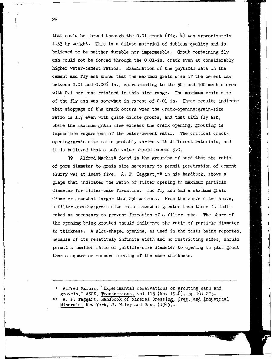
39. Alfred Machis* found in the grouting of sand that the ratio
of pore diameter to grain size necessary to permit jenetration of cement
slurry was at least five. A. F. Taggart,** in his handbook, shows a
gl-aph that indicates the ratio of filter opening to maximum particle
diameter for filter-cake formation. The fly ash had a maximum grain
d me ,er somewhat larger than 250 microns. From the curve cited above,
a filter-opening:grain-size ratio somewhat greater than three is indi-
cated as necessary to prevent foTmation of a filter cake. The share of
the opening being grouted should influence the ratio of particle diameter
to thickness. A slot-shaped opening, as used in the tests being reported,
because of its relatively infinite width and no restricting sides, should
permit a smaller ratio of jarticle-size diameter to opening to pass grout
than a square or rounded opening of the same thickness.
* Alfred Machis, "Experimental observations on grouting sand andgravels," ASCE, Transactions, vol 113 (Nov 1948), pp 181-205.
S* A. F. Taggart, Handbook of Mineral Dressing, Ores, and Industrial
Minerals, New York, J. Wiley and Sons (1945).
23
Effect of Intrusion Aidand RDA on penetrationcharacteristics of grouts
40. Fig. 4 shows that when Intrusion Aid was added to neat grout
when grouting a 0.02-in. crack the resulting water-cement ratio was re-
duced 0.03 at 25-psi, 0.08 at 50-psi, and 0.17 at 100-psi pumping pres-
sure, or an average reduction of 0.09 for all three pressures. When
Intrusion Aid was used in 1 cement:l fly ash grout, no reduction in water-
cement ratio but rather an increase of 0.43 resulted in grouting the
0.02-in. crack at 25 psi. However, a 0.02 reduction in water-cement
ratio resulted at 50 psi and a 0.09 reduction at 100 psi.
41. The use of Intrusion Aid in grouting the 0.03-in. crack with
neat grout allowed a reduction in water-cement ratio of 0.07 at 25 psi,
0.11 at 50 psi, and an unknown amount at 100 psi since the cement plus
Intrusion Aid grout at this pressure was not thickened to refusal. The
use of Intrusion Aid in grouting the 0.03-in. crack with 1 cement:l fly
ash grout apparently caused an increased water-cement ratio of 0.03 at
25 psi, a decrease of 0.01 at 50 psi, and a decrease of 0.03 at 100 psi.
42. Fig. 4 also shows that the use of RDA in neat grout permitted
a reduction of 0.01 at 25 psi, of 0.12 at 50 psi, and of 0.09 at 100 psi, For an averagc reduction of 0.07 in the minimum water-cement ratio that
would penetrate a 0.02-in. crack. In grouting the 0.03-in. crack, the
average reduction in water-cement ratio was 0.04 for the three pumping
pressures used. The use of RDA in 1 cement:l fly ash grout appaiently
allowed a reduction of 0.07 at 25 psi, of 0.03 at 50 psi, and an increase Ijof 0.01 in the water-cement ratio at 100 psi when grouting the 0.02-in.
crack. In grouting the 0.03-in. crack with cement-fly ash grout a slightly
increased water-cement ratio was required for penetration at -ll three
pressures used.I
43. For penetration of a given crack thickness, Intrusion Aid,
seemed to be a little more efficient in lowering the water content of
grout than RDA. That is, the Intrusion Aid was slightly more effi-ient
than RDA as a fluidifier. However, little appears to be gained from use
Of either material except where it might be desirable to inj, ct low
24
water-cement ratio grout under low pressure.
Quality of hardened grout
films from visual observation
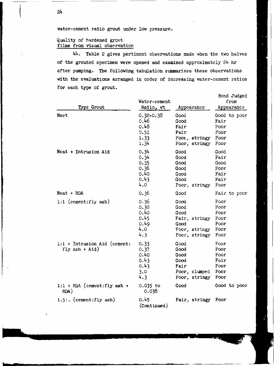
44. Table 2 gives pertinent observations made when the two halves
of the grouted specimen were opened and examined approximately 24 hr
after pumping. The following tabulation summarizes these observations
with the evaluations arranged in order of increasing water-cement ratios
for each type of grout.
Bond JudgedWater-cement from
Type Grout Ratio, wt Appearance Appearance
Neet 0.32-0.38 Good Good to pooro.46 Good Fair0.48 Fair Poor0.51 Fair Poor1.33 Pool, stringy Poor1.34 Poor, stringy Poor
Neat + Intrusion Aid 0.34 Good Good
0.34 Good Fair0.35 Good Good0.36 Good Poor0.40 Good Fair0.43 Good Fair4.0 Poor, stringy Poor
Neat + RDA 0.36 Good Fair to poor
1:1 (cement:fly ash) 0.36 Good Poor0.38 Good PoorO.40 Good Poor0.45 Fair, stringy Pooro.49 Good Poor4.0 Poor, stringy Poor4.3 Poor, stringy Poor
1:1 + Intrusion Aid (cement: 0.33 Good Poorfly ash + Aid) 0.37 Good Poor
O.4O Good Pooro.43 Good Fair0.43 Fair Poor3.0 Poor, clumped Poor4.3 Poor, stringy Poor
1:1 + RDA (cement:fly ash + 0.035 to Good Good to poorRDA) 0.038
1.5:. (cement:fly ash) 0.45 Fair, stringy Poor(Continued)
25
Bond JudgedWater-cement from
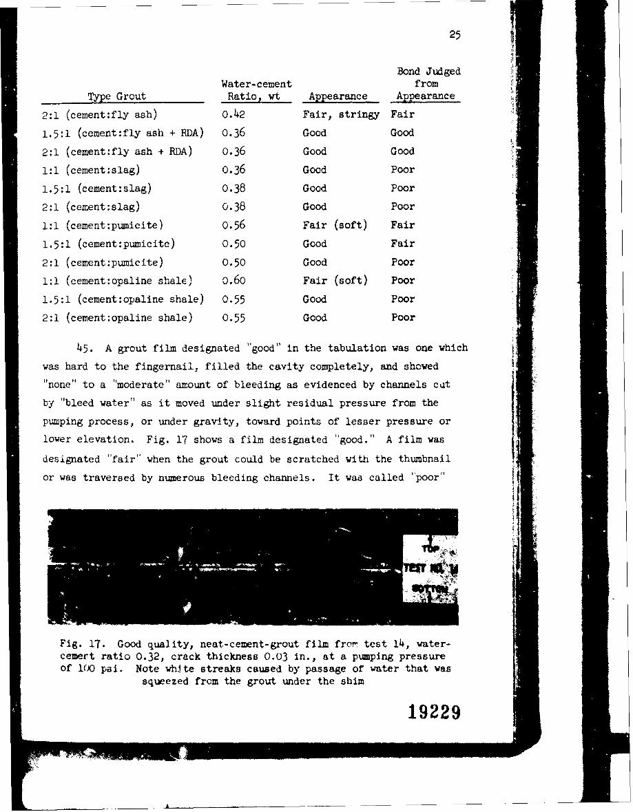
Type Grout Ratio wt Appearance Appearance
2:1 (cement:fly ash) 0.42 Fair, stringy Fair
1.5:1 (cement:fly ash + RDA) 0.36 Good Good
2:1 (cement:fly ash + RDA) 0.36 Good Good
1:1 (cement:slag) 0.36 Good Poor
1.5:1 (cement:slag) 0.38 Good Poor
2:1 (cement:slag) 0.38 Good Poor
1:1 (cement:pumicite) 0.56 Fair (soft) Fair
1.5:1 (cement:pumicite) 0.50 Good Fair
2:1 (cement:pumicite) 0.50 Good Poor
1:1 (cement:opaline shale) o.6o Fair (soft) Poor
1.5:1 (cement:opaline shale) 0.55 Good Poor
2:1 (cement:opaline shale) 0.55 Good Poor
45. A grout film designated "good" in the tabulation was one which
was hard to the fingernail, filled the cavity completely, and sovwed
"none" to a "moderate" amount of bleeding as evidenced by channels cut
by "bleed water" as it moved under slight residual pressure from the Fpumping process, or under gravity, toward points of lesser pressure or
lower elevation. Fig. 17 shows a film designated "good." A film was
designated "fair" when the grout could be scratched with the thumbnail
or was traversed by numerous bleeding channels. It was called "poor"
.3-.
Fig. 17. Good quality, neat-cement-grout film from test 14, water-cemert ratio 0.32, crack thickness 0.03 in., at a puping pressureof 100 psi. Note whIte streaks caused by passage of water that was
squeezed from the grout under the shim
19229
! ! -
*26
when it was quite soft or when the film occurred in lenses or streaks
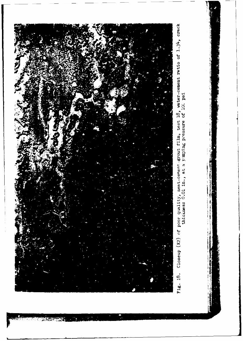
and could not be considered a continuous sheet of material. Fig. 18
shows a close-up of a poor-quality film.
46. Bond was considered "good" when approximately 40 per cent or
more of the film adhered to tie upper slab when the specimen was opened;
"fair" when the adherence was approximately 25 to 40 per cent; and "poor"
when the adherence was less than approximately 25 per cent.
47. It will be noted that the appearance of all the grouts having
a water-cement ratio of 0.6 or less was "good" to "fai:," and that where
"poor" grout was encountered the ratio was 3.0 or higher. There are no
intermediate values with the water-cement ratios ranging from 0.6 to 3.0,
but it is only logical to assume that the quality of such films would
have been "fair" to "poor." A direct comparison of the quality of dif-
ferent types of grout having the same water-cement ratio is not possible
from the present data. However. judging from the tond evaluations, the
use of Intrusion Aid appeared to be of some slight benefit in increasing
adherence of the film to the top slab; but for grouting a horizontal open-
ing between two nonabsorbent surfaces where v high-quality grout would
be required, which would assuredly adhere to the top as well as the bottom
of the cavity, a water-cement ratio not exceeding approximately o.46 and
neat grout should be used. The use of fly ash, judging from these qual-
itative data, may have had an adverse effect on the bond between top and
bottom slab, although the quality of the films, from visual observation,
was usually good. There was an apparent tendency toward clumping of the
solids in some cases.
48. RDA in the cement-fly ash grouts tended to make them softer
at 24 hr, but appeared to counteract to a large vxtenT the tendency to
agglomerate, ard improved the bond to the top slab.
49. The use of slag, pumicite, and the opaline shale tended to
improve the appearance of the grout films to - marked extent. Visual
evidencc of bleeding wa6 entirely lacking with all th- puicite nd
opaline shale grouts and with the 1 slagCl cement grout. The 1.5
cement:l slag grout showed slight bleeding Lnd te I ccrent:l slag
grout showed moderate blceiing. All three slaC-grovt1 films were hard
-*N
491k
07.
Isr
4-4
4~C
-404
44-
28
to the fingernail at 24 hr; however, the 1 cement:l pumicite grout could
be dented by a fingernail at 24 hr and the 1 cement:l shale grout could
be slightly scratched by a fingernail at 24 hr. Bonding to the top slab
did not seem to be improved by use of slag, pumicite, or opaline shale.
Strength of grout
f iLas judged by shear tests
50. An attempt was made, during stage 2 of the tests, to measure
the bond strength developed betwccn top slab and the grout by making
shear tests at 120 days age on sections of grouted specimens cut to 10-
in. lengths. Three 0.01-in. cracks were grouted at 50 psi with various
grouts as listed below, all with a water-cement ratio of 0.45 and with
pressure maintained on the specimens for 15 min after pumping:
Type Grout Test No. Remarks
Neat + Intrusior Aid 46ANeat 481 cement:l fly ash 49 Came apart in handling1 cement:l fly ash 54 Came apart in handling1 cement:l fly ash + Aid 50 Came apart in handling
51. The following results were obtained:
Specimen Section Shear Resistance, psi
46(1) 5046(2) Came apart in handling46(3) 18046(4) 7048(1) 6548(2) 3048(3) 5048(4) 6o
Test values were quite low for the neat-grout and neat-grout plus Aid
specimens tested, indicating very little bond. Those specimens contain-
ing fly ash did not develop enough bond to peimit making a test.
29 t
PART IV: TESTS OF GROUT CHARACTERISTICS
4Cons istency
52. A satisfactory device for measurement of consistency is highly
desirable and would enable the grouting crew to suit the quality and
pumpability" of the grout to the grouting conditions encountered. Con-
sistency measurements were made on the grout itself by means of a piano-
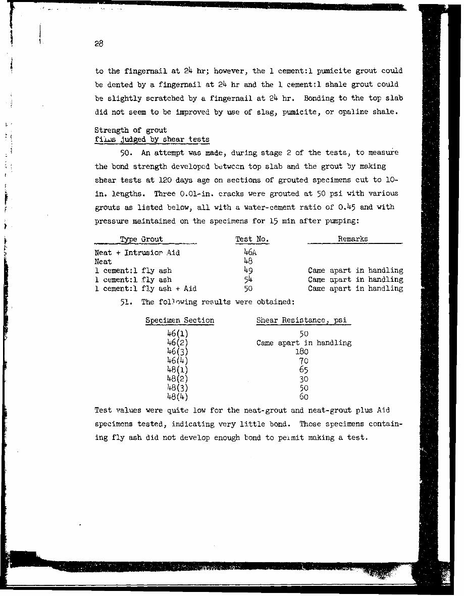
wire, pendulum-type viscosimeter, fig. 19, by a flow cone, and by a
unit-weight device.
53. The viscosimeter is an instrument
developed by Professor R. E. Davis of the
University of California, Berkeley, and the
Bureau of Reclamation. The viscosity or con-
sistency of a slurry is measured by placing a
sample in a shallow metal container mounted on
a motor-driven turntable. A wire spider is
suspended from a piano wire and is submerged
in the sample of grout. A weight holds the
piano wire taut. Torque is inrparted to the
spider and piano wire by the turning container
of grout. The number of degrees of torque
varies with the consistency of the sample
being tested.
54. The flow cone is simply, as its
name implies, a cone with a specified orifice
from which a known volumc of liquid flows in
a certain length of time, depending upon its
consistency. The flow (one used was one
developed by the Prepakt Concrete Company and
contained 1725 ml of grout. This amount of
grout was discharged through a pipe orifice,
1-1/2 in. long by 1/2-in. inside diameter, Fig. 19. Piano-wire
in the bottom of the cone. Flow was timed viscosimeter
30
with a stop watch. In some of the tests the discharge pipe was modified
to 6 in. in length and 3/8-in. inside diameter.
55. The unit weight device for consistency determinations was
designed by the Ohio River Division Laboratories for use with neat-
cement grout and consisted of a measure and specially graduated beam
"or translating unit weight into water-cement ratio. The device is
described in Engineer Bulletin, Civil Works No. 48-4, 18 May 1948.
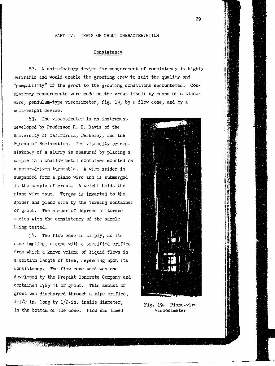
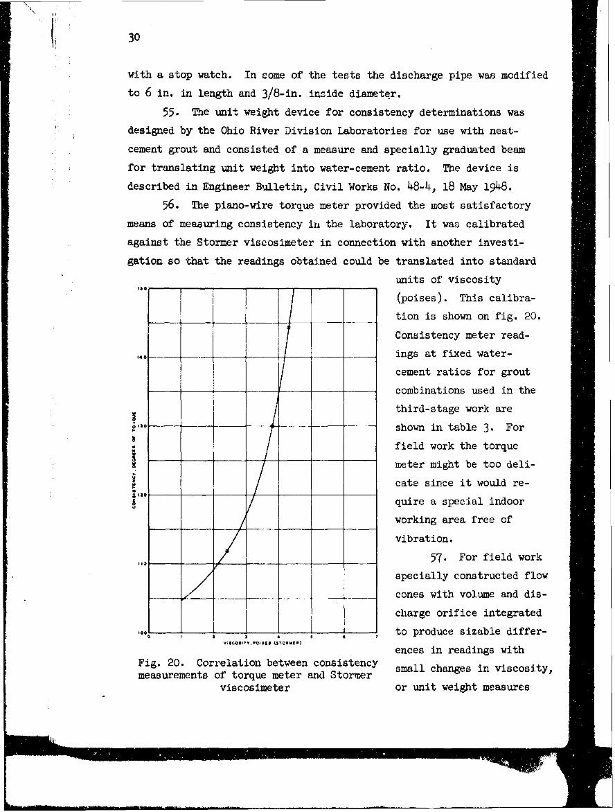
56. The piano-wire torque meter provided the most satisfactory
means of measuring consistency in the laboratory. It was calibrated
against the Stormer viscosimeter in connection with another investi-
gation so that the readings obtained could be translated into standard
units of viscosity
(poises). This calibra-
tion is shown on fig. 20.
Consistency meter read-
140 ings at fixed water-
cement ratios for grout
t combinations used in the
I third-stage work are
130-- shown in table 3. For
a Ifield work the torque
1 meter might oe too deli-
_cate since it would re-
Iquire a special indoor
-_ working area free of
vibration.
57. For field work
specially constructed flow
..... ... cones with volume and dis-
charge orifice integrated
1,00 to produce sizablc dif1tr-VISCOSITY. POISES (STORI()
ences in readings with
Fig. 20. Correlation between consistency small changes in viscosity,
measurements of torque meter and Stormerviscosimeter or unit weight measures
31
.,o I jzIzIz zz
ISO _ L EGEO
I - NEAT CEMENT0 ---- a- CEMENT ? AIgoI----- I CEMENT: I FLY ASHA- A- CEMENT I fLY ASH t IOA---- CEMENT. I SLAG
_40 ___ - 5 CEMENT I PWICITEX X 2 CEMENT I ORALINE SMALE
12 ...... -F -------\00 \S'--
0 10 20 30 40 so 60 70 0 oFLOW IN CU FT PE mR
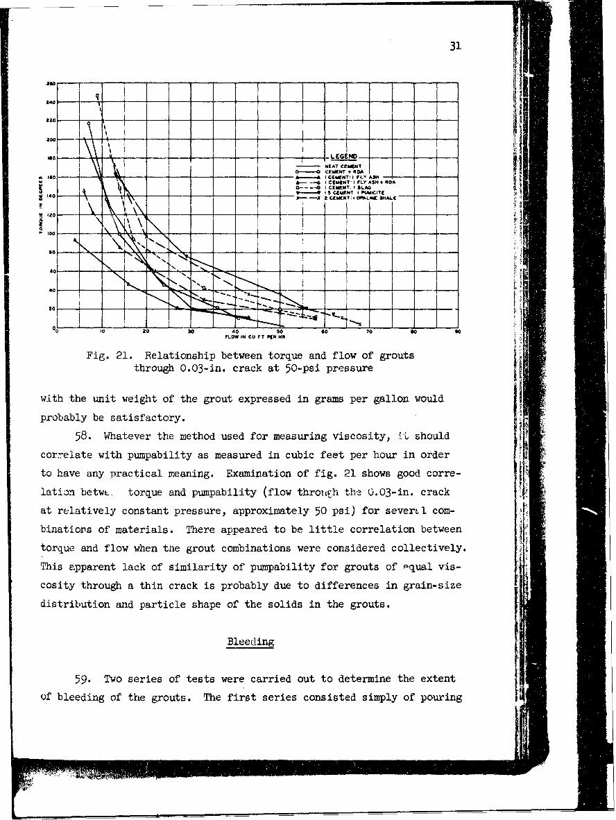
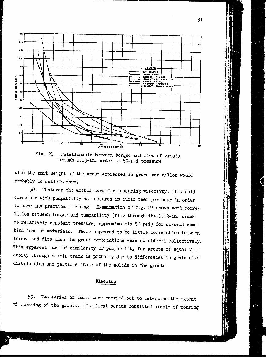
Fig. 21. Relationship between torque and flow of groutsthrough 0.03-in. crack at 50-psi pressure
with the unit weight of the grout expressed in grams per gallon would
probably be satisfactory.
58. Whatever the method used for measuring viscosity, It should
correlate with pumpability as measured in cubic feet per hour in order
to have any practical meaning. Examination of fig. 21 shows good corre-
lation betwL torque and pumpability (flow throuF-h th- 0.03-in, crack
at relatively constant pressure, approximately 50 psi) for sever~l com-
binatiors of materials. There appeared to be little correlation between
torque and flow when the grout combinations were considered collectively.
This apparent lack of similarity of pumpability for grouts of equal vis-
cosity through a thin crack is probably due to differences in grain-size
distribution and particle shape of the solids in the grouts.
Bleeding
59. Two series of tests were carried out to determine the extent
of bleeding of the grouts. The first series consisted simply of pouring
30
with a stop watch. In come of the tests the discharge pipe was modified
to 6 in. in length and 3/8-in. inside diameter.
55. The unit weight device for consistency determinations was
designed by the Ohio River Division Laboratories for use with neat-
cement grout and consisted of a measure and specially graduated beam
for translating unit weight into water-cement ratio. The device is
described in Engineer Bulletin, Civil Works No. 48-4., 18 May 1948.
56. The piano-wire torque meter provided the most satisfactory
means of measuring consistency in the laboratory. It was calibrated
against the Stormer viscosimeter in connection with another investi-
gation so that the readings obtained could be translated into standard
units of viscosity
(poises). This calibra-
Ition is shown on fig. 20.
Consistency meter read-
,,.- ings at fixed water-
cement ratios for grout
combinations used in the
third-stage work are
--3 shown in table 3. For
field work the torque
meter might be too deli-
cate since it would re-
quire a special indoor
working area free of
vibration.
110 57. For field work
specially constructed flow
- __ _cones with volume and dis-
charge orifice integrated-00 to produce sizable differ-
1 3 4 0
VWiCOSIITYPO4II (STORIER)
ences in readings withFig. 20. Correlation between consistency small changes in viscosity,measurements of torque meter and Stormer
viscosimeter or unit weight measures
31
220 ....
IS - L GEN , ------- -- , -NEAT CEMENT
1W - - -- CEMENT RDA
-----A CEMENT: I LY AS H.&_ I CEMENT I FLY ASH RDA
1, 1402 CEMENT. I OLGN
5---9I CEMENT I PUMICITEZl - Xa i 2 C I E Wr T I O F IA L IN E I S A L l"
20 0J
II
tc--h3' " 5
3O2 0 40 so so 70 so 0FLOW IN CU FrT fltO NOl
Fig. 21. Relationship between torque and flow of groutsthrough O.03-in. crack at 50-psi pressure
with the unit weight of the grout expressed in grams per gallon would
probably be satisfactory.
58. Whatever the method used for measuring viscosity, it shouldcorrelate with pumpability as measured in cubic feet per hour in orderto have any practical meaning. Examination of fig. 21 shows good corre-lation between torque and pumpability (flow through the 0.03-in. crackat relatively constant pressure, approximately 50 psi) for several com-binations of materials. There appeared to be little correlation betweentorque and flow when the grout combinations were considered collectively.This apparent lack of similarity of pumpability for grouts of equal vis-cosity through a thin crack is probably due to differences in grain-sizedistribution and particle shape of the solids in the grouts.
Bleeding
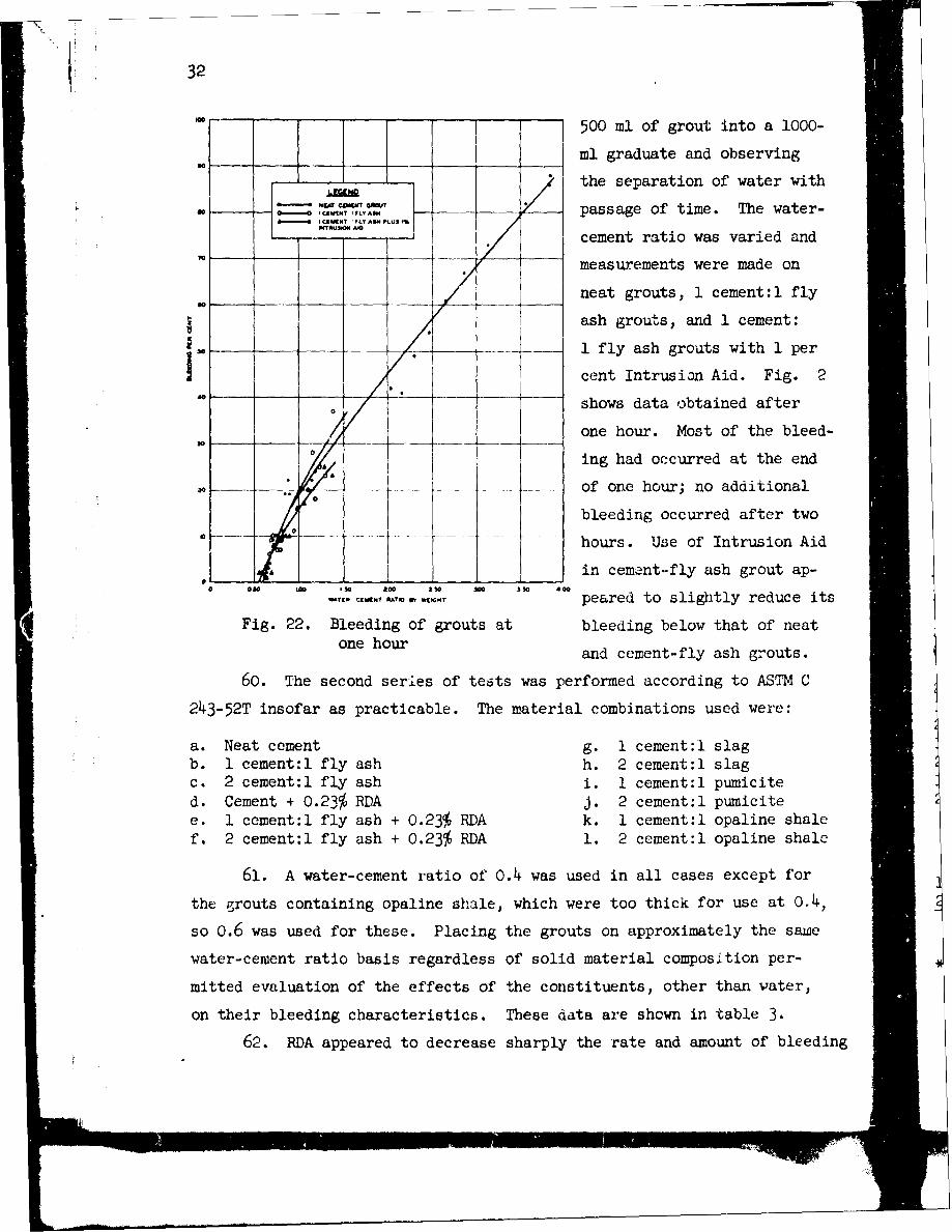
59. Two series of tests were carried out to determine the extentof bleeding of the grouts. The first series consisted simply of pouring
32
--500 ml of grout into a 1000-
ml graduate and observing
the separation of water with
- ----' -:C __/ passage of time. The water-
cement ratio was varied and
I "measurements were made on
neat grouts, 1 cement:l fly
ash grouts, and 1 cement:
__ -_-1 fly ash grouts with 1 perF0 cent Intrusion Aid. Fig. 2___ _ __ - shows data obtained after
one hour. Most of the bleed-/° ing had occurred at the end
....- of one hour; no additional
bleeding occurred after two
hours. Use of Intrusion Aid
00Iin cement-fly ash grout ap-
M9 CEMENT RATIO Of *EIGHT peared to sligitly reduce its
Fig. 22. Bleeding of grouts at bleeding below that of neatone hour and cement-fly ash grouts.
60. The second series of tests was performed according to ASTM C
243-52T insofar as practicable. The material combinations used were:
a. Neat cement g. 1 cement:l slagb. 1 cement:l fly ash h. 2 cement:l slagc. 2 cement:l fly ash i. 1 cement:l pumicited. Cement + 0.23% RDA J. 2 cement:l pumicitee. 1 cement:l fly ash + 0.23% RDA k. 1 cement:l opaline shalef. 2 cement: fly ash + 0.23% RDA 1. 2 cement: opaline shale
61. A water-cement ratio of 0.4 was used in all cases except for
the grouts containing opaline shale, which were too thick for use at 0.4,
so 0.6 was used for these. Placing the grouts on approximately the same
water-cement ratio basis regardless of solid material composition per-
mitted evaluation of the effects of the constituents, other than water,
on their bleeding characteristics. These data are shown in table 3.
62. RDA appeared to decrease sharply the rate and amount of bleeding
33
when used in neat grout. It appeared to act in a similar manner in the
grouts with fly ash but to a lesser extent. Fly ash itself appeared to
slow down the rate of bleeding but did not affect the total amount of
bleeding. Slag appeared to lessen both the rate and amount of bleeding to
a small extent. Both the pumicite and opaline shale sharply decreased the
amount of bleeding and, to a somewhat lesser degree, the rate of bleeding.
Setting Time
63. Setting times of grouts containing the same constituents asAl
used for the second series of bleeding tests, and made with both 0.4
and 0.8 water-cement ratios, were determined. The determinations were
made by use of the 1-rm Vicat needle and small samples of grout placed
in shallow wide-mouthed vials. The data obtained are shown in the tabu-
lation below.
Water-cement Ratio Water-cement Ratioof 0.4 of 0.8
Setting Time, hr Setting Time, hrGrout Initial Final* Initial Final*
Neat cement 4 plus Under 18 4 plus Under 191 cement:l fly ash 6 plus Under 22 5 plus Under 212 cement:. fly ash 6 plus Under 22 7 Plus Under 23Cement + RDA 7 plus Under 23 6 plus 72**1 cement:l fly ash + RDA 22** Under 46 22** 30 to 462 cement:l fly ash + RDA 22** Under 46 26** 48**I1 cement:l slag 6** Under 22 8 plus 30**
2 cement:l slag 4 plus Under 20 5 plus Under 211 cement:l pumicite 4 plus Under 20 6 plus Under 222 cement:l pumicite 4 plus Under 20 5 plus Under 211 cement:l opaline shale Too dry to test 6 plus 30**2 cement:l opaline shale Too dry to test 5 plus 29**
Water-cement Ratioof o.6t
1 cement:l opaline shale 3.5 Under 16*2 cement:l opaine shale 6 plus Under 21*
* Exact setting time could not be obtained because of hours-of-worklimitations.Approximate setting time.
t Fluid grouts could not be made at a 0.4 water-cement ratio using theopaline shale. The ratio of 0.6 was tested for information only;this ratio represents about the lowest ratio for fluid grout withthis material.
• , I II I I
34
614. Setting time is obviously important when grout is expected to
cut off percolating water. In grouting by stages, it also controls the
time that must elapse before holes ca~n be cleared out and drilling resumed.
65. Setting timaes could not be determined exactly because of hours-
of-work limitations. RDA appeared to lengthen the setting time by as
much as three times that for the other grouts. The longest final setting
time for any grout without RDA was approximately 30 hr (1 cenient:l opaline
shale at 0.8 water-solids ratio). The longest setting time observed for
the whole series was approximately 72 hr for neat grout with RDA at a 0.8
water- cement ratio.
Solub ility
66. Two 50-nil portions of each of the selected grouts, listed in
the 0.4 and 0.8 water:cement portions of the tabulation in paragraph 63,
0
CALC 1UOA
I II ats
OAV3 LIACMkG______ ___ il-
I-A UVIA -01- v CUE 7- .- OAT CuAC ---- -
0 4V~ 4 SM 10LI3 OAT1O OS WAY(* SOL. 103 PLAT0
TQTAL sOIID~
Fig. 23. Total solids and calcium leached from grouts
35
were placed in stoppered 2u0-ml flasks and one was cured for 7 days, the
other for 90 days. At the end of the curing age, the samples were leached vwith 50 ml of distilled water for periods of 2, 7, 28, and 90 days. Leach
water was then tested for pH, total solids, and calcium ion. The results
of these tests are shown in table 4 with total solids and calcium ex- tpressed both in parts per million found ir 200 ml of leach water and as
a percentage based on the amount of solids and calcium in the original 9
50 ml o grout. The results are also shown graphically for total solids
and calcium on fig. 23.
67. Unfortunately reaction occurred between the Pyrex glass flasks
in which the grouts were cured and the alkalies in -he grouts, causing
many to crack after several weeks storage permitting the water to leak
out. No test results are plotted on fig. 23 from specimens which were
in the cracked flasks.
Conclusions
68. Conclusions drawn from the unspoiled tests are:
a. Grouts exposed to leaching after only 7 days curing ap-peared to be somewhat more susceptible to leaching thanthose cured 90 days.
b. About one-half of the dissolved material that leached out 6of the 0.4 water-solids ratio grouts was calcium, whereasabout one-third of the dissolved material from the 0.8
water-solids ratio grcuts was calcium.
c. Increasing the water-solids ratio from 0.4 to 0.8 approx-imately doubled the amount of calcium and more than doubledthe total solids in the leach water.
d. RDA did not materially affect the solubility of the groutsmade with a water-solids ratio of 0.4. Total solubilitywas increased and calcium solubility was decreased forthe RDA grouts at a water-solids ratio of 0.8.
e. Fly ash did not appear to r:i, r .l_,.ly affect solubility ofthe 0.4 ratio grouts. Solubility of the 0.8 ratio groutsseemed to be increased by use of fly ash.
f. Behavior of RDA in the fly ash grouts was the same as inthe neat-cement grout.
g. Slag reduced the solubility of all constituents. The
36
effect on decreasing solubility was more marked at thehigheL water-solids ratio and was more pronounced for the2 cemcnt~. slag then for the I cement:l slag grout.
h. Pumicite appreciably increased the over-all solubilityof the 0.4 ratio grouts, but slightly decreased the solu-bility of the 0.8 ratio grouts. Calcium solubility wasappreciably increased in the 0.4 ratio grouts and onlyslightly increased in the 0.8 ratio grouts.
i. The opaline shale materially reduced the solubility ofall constituents. Total solids were reduced by about50 per cent and calcium by about hO per cent.
37
PART V: SUMMARY OF RESULTS
69. The reader should keep in mind in evaluating the data that the
investigation described comprises only a single set of tests per condition.
Factors Influencing Penetration of Grouts
Surface texture
70. It was found that the surfaco condition of the specimens, that
is, whether the surfaces to be grouted were smooth or roughened, had a
pronounced effect on how thick a grout could be forced through the cracks.
The smoother surfaces permitted *he use of censi erably lower water-
cement ratios than did the roughened surfaces for all three crack thick-
nesses tested.
Water-cement ratio
71. The water-cement ratio influenced the thickness of crack that
could be penetrated at a given pumping pressure. Neat grout with a water-
cement ratio of 0.43 would penetrate the 0.03-in. crack at 25 psi, but
the water-cement ratio had to be increased to 2.67 before neat grout
would penetrate the 0.01-in. crack at the same pressure.
lumping pressure
72. An approxim, &ely straight-line pressure drop occurred along
the specimens while the 0.02- and 0.03-in. cracks were being grouted.
The pressure was either 205, 50, or 100 psi where the grout entered, and
was 0 psi where it emerged with intermediate pressures measured along
the length of the specimen. Vhe pressure drop was steeper for the first
12 in. of specimen length than for the remaining 36 in. uhen the 0.01-in.
crack was being grouted. The steepness of the gradient for the first 12
in. increased as the grout thickened and the flow decreased.
73. Increased pumping pressures caused directly proportionate in-
creases in grout flow. At identical water-cement ratios, pressures, and
crack thicknesses the neat-cement grout had least fClow, cement-fly ash
grout had more flow, and neat grout plui Intrusion Aid had still unore
flow. However, thL flow was not greatest, as might be expected, with
S -~,- '--#
38
cement-fly ash grout plus Intrusion Aid. Data on the cement-fly ash-
Intrusion Ai grout were anomalous and inconclusive.
74. When the crack width was 0.02 or 0.03 in. the minimun water-
cement ratio (thickness of grout) the crack would accept was little af-
fectad by the grouting oressure, however the thickness of the grout that
would penetrate the 0.01-in. crack depended some-what on pressure. At
25 psi, the thickest grout that woul penetrate the 0.01-in. crack had
a water-cement ratio of 2.67. When the pressure was increased to 50 psi,
grout with a water-cement ratio of 1.33 would penetrate, but a further
increase in pumping pressure to 100 psi did not permit use of' still
thicker grout.
Grain size
75. The use of a No. 50 sieve cloth for straining the grout seemed
beneficial and probably the 1zc of a 1Fo. 60, or even a No. 100 cloth, if
vibrated, would be practicai in removing oversized particles which cause
trouble in grouting the tightest seams. The fly ash contained grains of
material larger than 0.01 in. and grouts containing fly ash would not
penetrate the 0.01-in. fissures. Based on the maximum grain size of the
cement, 0.006-0.01 in., and the thInnest cracks grouted, 0.01 in., the
ratio of crack thickness to grain size should not be less than 1.7, and
probably safer ratios would be 3.0 or more (see paragraphs 38 and 39).
76. The use of fly ash 4ppears limited to grouting lax er cracks
unless a supply of fine material can be obtained, or unless fly ash can
be processed, possibly by air separation, to remove the larger granules.
No attempt was made to grout 0.01-in. cracks with grout containing ground
slag, pumicite, or opaline shale. Difficulty would doubtless have been
encountered with the slag and shale whose grain size exceeded 0.01 in.
77. The use of more finely ground cements, such as high-early
strength cement, o: ordinary cement processed through an air separator
might be feasible.
Chemical fluidifiers
78. The use of Intrusion "id appeared to be a help in reducing the
water ratio of the grout that could be pumped through cracks of 0.03-in.
*,hickness with roughened surface, and 0.03- and 0.02-in. thickness with
-7 V7M .4~ 7.~t r5; ~A' tt4:~A >'t~ ~§Aw~ 4 v7W
39
smooth surfaces. It is believed that the Aid should also have promoted
use of lower water-cement ratio grout for the roughened 0.02-in. crack
but did not in these tests because of surface factors in the specimens.
Intrusion Aid was of no help in promoting penetration of 0.01-in. cracks
at any water ratio tried be'!ause of the limits of penetration placed upon
the grout containing fly ash by the coarseness of the fly ash. Penetra-
tion of 0.01-in. cracks with neat grout containing Intrusion Aid was not
tried. The use of Intrusion Aid appeared to cause a small reduction in
bleeding and a slight expansion in the grouts.
79. Intrusion Aid and RDA appeared to increase the fluidity of
the neat grouts so that a seam of given thickness would pass a greater
amount of such grout than of plain grout having the same water-cement
ratio; conversely, grout with fluidifiers, at a lower water-cement ratio
and at a given pressure, would penetrate a given crack better than grouts
without fluidifiers.
80. Intrusion Aid seemed to be more effective with neat grouts
than with grouts containing fly ash. The cement-fly ash grout with In-
trusion Aid did not penetrate either the 0.02- or the 0.03-in. seams
significantly better than the same grouts without Aid.
Mineral fines
81. Fly ash appeared to increase the fluidity of the grouts in
which it was used. The ground slag also appeared to increase fluidity,
however this was not conclusive. The pumicite and opaline shale both
greatly stiffened the grouts in which they were used; however, at com-
parable consistency with neat grout, the pumicite and opaline shale
grouts pumped better than the neat grout. At equal consistency the fly
ash and slag grouts pumped about the same as neat grout.
Factors Affecting Quality of Grout Films
Water-cement ratio
82. 'he grout films having water-cement ratios of 0.5 or less
appeared hard and filled the fissures completely with little evident
bleeding. However, the bond of top to bottom half of the grouted specimen
40
was not considered good except when water-cement ratios were lower than
0.4.
83. Bleeding occurs in grouts having water ratios in excess of
0.50, and becomes more severe the higher the unit water content. A nar-
row band of dense hard grout was always found next to the shim beneath
which water had escaped. This band of dense grout was always narrow,
never exceeding 3/4 in. in width, no matter what the original water con-
tent. It has frequently been hypothesized that the original water con-
tent of a grout is not very important as the excess water is squeezed
out into the pores of the rock and extremely fine seams (too fine to ac-
cept grout) leaving a dense hard material filling the cavity. It was
not found possible to squeeze this water out with the 100-psi grouting
pressure used, in the 10 to 15 minutes during which pressure was main-
tained, except in a narrow band around the edge of the specimen, even
with the outer edges of the specimens open to the air at 0 (relative)
pressure.
84. Setting time increased with water content. Neat grout with
a water content as high as 3.8 required ten days to set in the setting-
time tests, and had not set in 13 days when spread into a thin film in
the grouting tests. Such thin grout containing Intrusion Aid did not
set in 14 days in the setting-time tests. These thin grouts can be shown
to be incapable theoretically of developing any compressive strength; see
appendix B. The higher water-solids ratio grouts were also much less
resistant to leaching than those with lower ratios.
Chemical fluidifiers
85. Bonding of the hardened grout films to the top slab was poor
(25 per cent or less of film adhering to top) for all grouts except those
containing fly ash with RDA where the bond was considered good (40 per
cent or more adhering to top). Bond strength as measured by shear tests
on neat and neat-cement plus Intrusion Aid grouts was relatively low al-
though the use of Intrusion Aid appeared to somewhat increase bonding
between top and bottom halves of the specimen in neat grout. RDA did
not appear to benefit the bond condition of specimens intruded with neat
grout.
-- own
41
86. Both Intrusion Aid and RDA prolonged setting time and reduced
bleeding. The solids in the fly ash grouts tended to clump or agglom-
erate. This tendency appeared to be reduced but not eliminated by the
fluidifier. Intrusion Aid was not used in the tests for solubility of
grout films, but RDA had little effect on the leaching characteristics
of the grouts tested.
Miueral fines
87. Hardened grout films containing fly ash showed evidence of
channeling action and apparent agglomeration. This tendency was not
roted when the slag., pumicite, and opaline shale were used. The use of
grouLd osl a pumicite, an]d opaline shale greatly improved the apparent
qual.ty of the grout film, virtually eliminating evidence of bleeding,
channeling, and agglomeration. Bond between top and bottom halves of
the specimens was not improved by use of the several mineral fines.
88. The use of fly ash had little apparent effect on the solu-
bility of the 0.4 water-ratio grouts, but appeared to ir,:2ease the solu-
bility of the 0.8 water-ratio grout. Slag reduced the leaching in all
cases with the most pronounced effect in the higher water-ratio grouts.
Pumicite increased the over-all solubility of the 0.4 ratio grout but
slightly decreased the over-all solubility of the 0.8 ratio grout. The
opaline shale greatly reduced the over-all solubility of both the iow-
and high-water-solids ra-io grouts in which they were used.
Curing
89. Grout, films cured for 90 days appeared more resistant to
leaching than those cured 7 days.
Measurement of Consistency
90. The measurement of consisterncy was readily accomplished in
the laboratory with the torsion viscosimeter. Changes in consistency
can also be detected and controlled readily by means of unit weight meas-
urements. The flow cone was not too sensitive to small changes in viscos-
ity although a cone with an orifice restricted enough to require more
time to discharge might prove suitable for field use. The torsion
.1
viscosimeter, because it is delicate and requires a quiet, level area
for operation, would not be as suitable for field as for laboratcry use.r
43
PART VI: CONCLUSIONS
91. The surface texture of a fissure has a distinct influence on
the thickness of grout that can be used to fill it. The smoother the
surface the lower the water-cement ratio of the grout can be and still
penetrate the crack.
92. The maximum grain size of the solids in the grout determines
the minimum crack width that can be grouted. The ratio of crack width
to grain size should probably be three or more.
93. The use of such materials as Intrusion Aid and RDA increases
the fluidity of grouts, to some extent., thereby promoting penetration of
a given crack width with grouts of a slightly lower water-cement ratio
than could be used successfully without thew. Bleeding can be reduced
somewhat and setting time increased by use of these materials.
94. It is impracticable to squeeze the excess water from a thin
grout, thereby leaving a dense, hard filler in the cavity, at the pres-
sures used in this program.
95. Bleeding largely prevents bonding of the grouting material to
the upper surface of the fissure.
96. The use of finely ground mineral admixtures such as granulated
blast-furnace slag, pumicite, and opaline shale can reduce the bleeding
of a grout and greatly improve the continuity and appearance of the
hardened grout film.
97. The solubility of a grout film is influenced by the water-
cement ratio and composition of the film and length of curing. Certain
mineral admixtures can be used to reduce the amount of leaching that a 4
grout film undergoes.
98. A straight-line pressure gradient occurs along a fissure being
grouted only if the crack is of sufficient width.
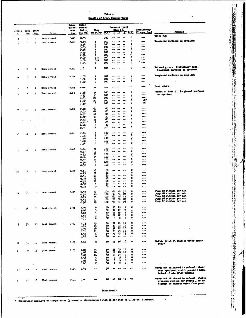
1i)
Table 1Results of Grwut PumvIrw Tests :
Crack Vater-Tkaick- cannat Wraes (pal)
Z'erlv! Test StsCe ness Ratio Flow ~. C~lta10. . NO .Grnu. i. (by _t) ft2 OtrS De) ctiOA
I h 1 eat ceecr.t 0.02 0.45 .... 100 . 0 -- Tral ru
S:eat cewc. O.G1 3.73 8 100 . 0 --- Roukened surfaces on specain
3134 7 00 . .3 5 GOO 0. .
2.55 3 100 .... 0
2.36 2 100 ... 02 . 2 0 1 .5 1 0 0 . . . . . . - 0 - - -2.06 0.9 10 ... -1.: 0 100 .... 0 --
'.01 7.6 2 100 ......- 0 -- Refused t Prelim ary test.
Roug.oad surface* on specimen
Neat Nmer.t 0.02 1.08 12, 100 .--- subosed surfaces on spseaimn1.04 7 100 . .. 0 --
1.02 0 100--------0 ---
, 1 Neat cetent 0.03 ---- - Test voided
4 1 Neatc cent 3.03 0.58 34 1o0 .....- --- Repeat of test 2. ltNaabens surfacs
0.55 30 100--------0 --- o. .. 0l tm
0.53 26 100-...... 0----0.52 22 100----...-0 2 'o.5o 6 100--- ... -0 36
7 i r eat cement 0.03 0.70 69 80-......-0 ---0.62 64 so 0 o0.57 62 6.--- 0 .
0.52 49 3 ... .. ..-- ---o. 25 o . - ---
0.242 12 80--------0 -- X0.40 0 S ......-o---
4 100- ----------- 0
, i 1 Neat ce n . 0.01 1.06 6 100-......-01.96 6 10---------------
1.-16 4 100 -- ..0
-.60 3 100D 01.34 0 100------------
* 17 i teat ,orx-nt 3.02 1.01 31 100-------- 0-------O.M -;'?o5 1O0 .... 00.73 20 1o--- ... 0 .----
0.64 15 100------- 0 ....--0.57 11 100-- ..... 00.54 6 .0 - - 00.52 0 100-- - - . .. 0 --
1I L N I;eat ce-mrt 0.03 0.51 1.8 80 ..... 0 ..
0.45 37 80 .. 00.241 27 so - 00.38 25 78-- ..... ----- -0.35 12 8o 0 0 -
0.32 5 80 - . 0 --0.32 0 80 .... 0 ...
11 , N e Uat cement 0.03 0.50 41 100 62 40 32 0 --- Pum 80 strokes per ain0.50 40 100 56 3' 22 0 --- pp 68 strokes per ma0.45 35 1oo 66 246 25 0 --- i 68 strokes per mn0.42 27 100 72 50 28 --- r 68 strokes per mln0.38 19 100 75 47 28 0 ... Pa 72 stroLes per min
uscrjLI nt 0.01 4.00 6 0 30 19 9 0
3.00 5 30 30 17 12.00 4 50 21 15 5 0 ---1.50 3 50 211 5 0 ---
1.3" 0 5o 9 6 4 0
35 3 g 2 Iesteent 0.02 1.33 25 50 3121 11 0 --1.io M1 5o 32 22 i2 o0 ..0.92 18 50 32 22 12 0
0.71 11 50 34 24 12 00.57 6 50 37 25 13 0 ---o.AS 0 50 .. .. .. .. ..-
1H. 3, . eat ceegnt 0.03 0.48 0 50 25 16 8 0 Rtio gutrati 1o
S y7 2 .:et cement 0.03 1.2o 55 50 35 2 1 00.86 5 28 20 12 00.67 "6 50 23 17 9 0 ---0.57 5 50 7 5 1 00.52 4 5o 8 6 2 0 --o.6 2 5 8 6 2 0 -
4, 1 " Oeat cc-rnt 0.03 0.245 -" 50 --------- --- Grout not tbickeed to efusel, shetest specimen. static pressure min- 4:tained 15 min after puspin
1 5 2 teat cement 0.03 2.0 w 0 0 O0 40 20 Grout not thickened to refusal, staticpressure applied for appoX 1 hr toattempt to squeeze vster frm IPAi
(Continued)
'Con istency measuired an torque mcter (piano-wire viscolutr) with spider Are of 0.125-iti. diameter.
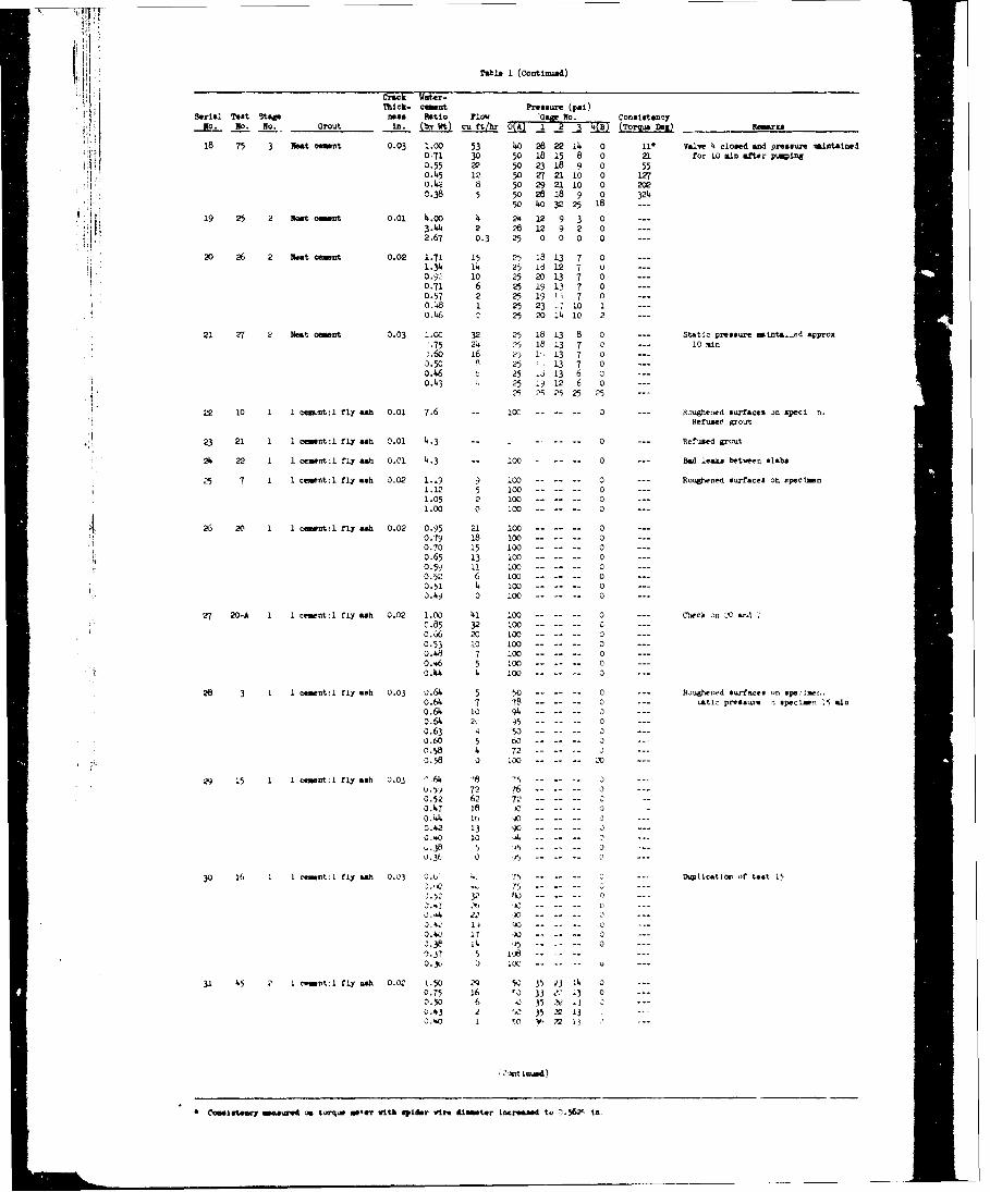
Table 1 (Conrtinued)
C Crack ate -Thick- cent Pressure (psi)4 Serial Test Stag s n i Ratio Fl1o wGa, No. Conslstency
18 75 3 Neat cemint 0.03 1.00 53 40 28 22 14 0 11* Valve 4 closed ad pressure maintained0 71 30 50 18 15 8 0 21 for 10 &inafter puing
j: 0.55 22 50 23 18 9 5504.5 12 50 2 21 10 0 1n0. 44 8 50 29 21 10 0 2020.38 5 50 28 18 9 0 324
50 40 32 5 18 --
19 25 2 Nat csmnt 0.01 4.00 4 24 12 93 03.44 2 26 12 9 2 0 --2.67 0.3 25 0 0 0 0 ---
20 26 2 Meato eent 0.02 1.71 15 25 18 13 7 0 ---1.34 14 25 18 12 7 o ---0.92 10 25 20 13 7 0 ---0.71 6 25 19 13 7 0 ---0.57 2 25 19 1 7 0 ---0.48 1 25 23 1. 10 1 ---0.46 7 25 20 14 10 2 ---
21 27 2 Nest cent 3.03 1.00 32 25 18 13 8 0 --- Static pressure ematnta.-.d approx
75 24 25 18 13 7 0 --- 10 in
.60 16 25 1, 13 7 0 ---0.50 P 25 .13 7 00.460 25 .J 13 6 0o.43 4 25 .9 12 6 0 ---
25 ?S 25 25 25 -.--
22 10 1 1 cenknt:l fly 0ah O.01 7.6 -- 10- ......- 0 --- 8oughened surface on peci n.
HefumeO grout
23 21 1 1 cmnt:l fly ash .O1 4.3 ... 0 --- Refused grout
24 22 1 1 cement : fly ash 0.01 4.3 -- 100-0 --- Bad leaks betwen slabs
7 1 ceent:l fly ash 0.02 1.19 9 100 ------ 0 --- Roughened surfaces on speclmen1.12 5 100 01.05 2 100--..... 0 -----1.00 0 100 ......-- -0--
26 20 1 1 cint:l fly ash 0.02 0.95 21 100 0 ---0 0.79 18 100 ------- 0 ---
0.70 15 100 - - - 0 ---
o.65 13 100-- .. 0 ---0.59 11 100----... 0 ---0.52 6 100--- ..... -----0.51 4 100 0 ---o.49 0 100--- ...... o .
27 20-A 1 1 c nt:l fly ah 0.02 1.00) 41 ......- 0 --- Chck on L ad "0.85 32 100 0 ---0.66 20 100-----.. 0 ---0.53 10 100---... 0 -- =0.48 7 100-...... 0 -=-0.46 5 100- - o 00.44 4 100 0
26 3 1 1 comnt:l fly ash 0.03 0.64 5 50 ..... 0 --- Rughe-d surfaces on e. 1 o.o.64 7 78------- 0 -- .atic pre sum n speclmen nmo.64 10 94 ...... a- ---0.64 2 5 --- 0 ---o.63 q 50 .. 0 ---o.60 5 w -......-- ---0.58 4 72 00.58 0 100 0 -
29 15 1 1 cnt:l fly ash 0.03 '.64 -' . .u.5 72 76 n0.52 6. 72 .0.47 18 ---------0.4" it, ------0.42 13 900.60 10 ,J ..-1.38 5 6...... 0----0.3t 0 1,) . ---
30 16 1 1 cent: fly ash 0.03 0.6' -. 75- ......------. Dulicatlo of test 1
0.52 3 P . . .. .0.4 0 ---3.42 ,U .. o --
0. 4 17 X .. .. ..- o----0.38 14 ,. .- -- 0 ---0.37 5 1 . . .0. 3K 0 1C
I1 45 2 1 cownt:1 fly ash 0.02 1.50 N9 54. 45 23 14 0OT5 16 "0 33 ?'" 13 0 ---0.50 6 .0 35 z.. 1 o ---1.43 2 .1 35 -- 130.60 1 o v 12 fl -
SCoweteacy smerwd on rasmotner vith epider vies &lmtor Increased to 7-S&2 in.
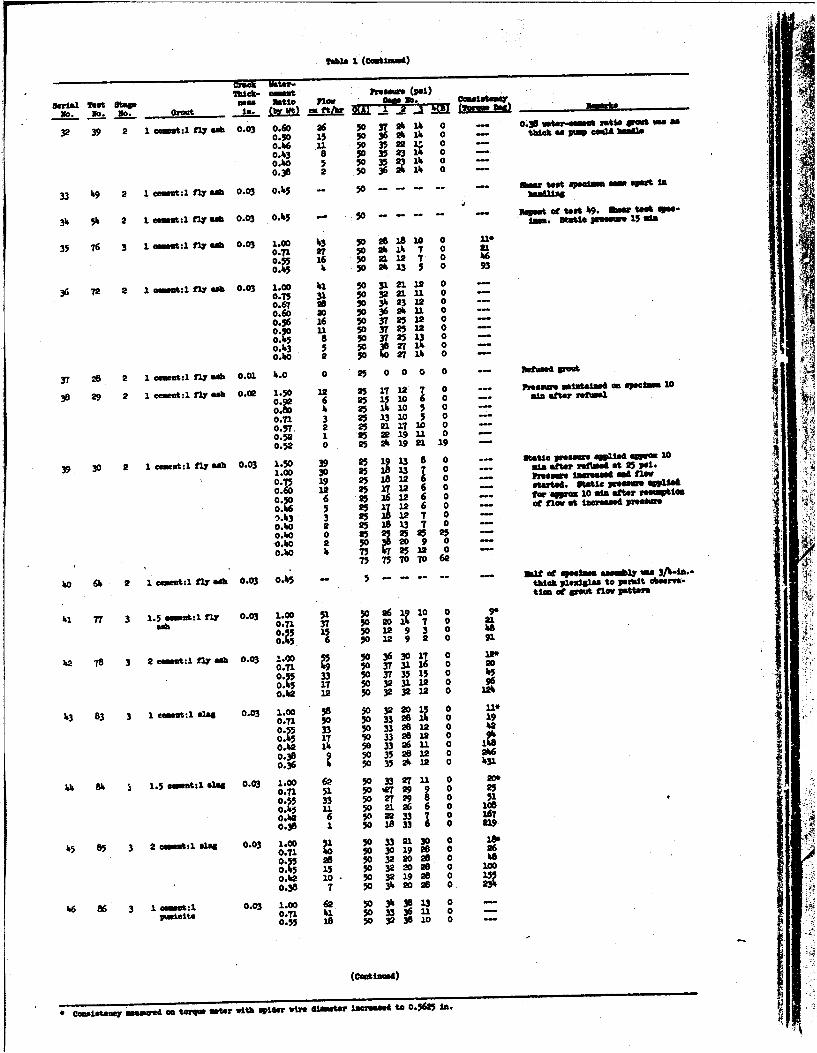
Tab"a I (COWMtMAm)luck- se(e (")
Serial Test Stae mm tLUO 11w 50. C.ist __
,0. O. O. Gr I- - -. j, "rm
32 39 2 1 emmt:1 2 oft 0.03 0.60 26 50 37 A 1 0 - 0.38btWOinub ratio Uoutinas
0.50 15 50 36 A A 0 - tu i FpCo bfsfine
o.A6 11 50 35 22 00.13 8 50 35 23 0 -
0.10 5 50 35 211 00.3 2 .5036 a 11 0 -
33 49 2 1. n t:l fly ca 0.03 0.15 - 50 -m . t- -e-l sm -- m m t u Inw 1
33 51 2 1 om:l fly l, 0.03 0.5 ) -" 50 CC- .t-t W. N10 Ot te e-
35 76 3 lei ft:ly li 0.03 1.00 13 50208 1810 0 1*
0.71 27 50 24 14 7 0 al16 50 21 127 0 6
11g 502A13 5 0 93
36 72 2 1m 1:1 M w 0.03 1.00 41 50 31 21 12 0 -
0.75 31 50 3221 11 0 -0.67 28 503 2312 0 -
0.60 20 5036A111 0 -
0.96 26 50 37 2512 0 -
OjO Li 50 37 5 2 -
8 50 3T25 1 00.13 5 50 1 o -
0.00 2 s 21 0 -
v 28 2 1 emot lfly so 0.01 1.0 0 25 000 0 -o o tIarsAPO
38 29 2 1 cet,:l flY 6 0.02 1.50 12 25 17 12 7 0 --- ssv m opee41wn 20
0 6 251 10 6 0 - a ta eua
11r I 25It1065 -
0.71 3 25 13 10 5 0 -
0.57 2 25 21 1710 0 -
0.52 1 25 2 019 11 0 -
0.52 0 25 A 19 21 19 -
39 30 2 1 emm&:lfly "h 0.03 1.50 39 25 1 13 8 0 -- Strtiepeu SW off-1 0
1.00 30 251 13 T 0 -- mi attr raf" at25 pal.
0.75 19 25 18 12 6 0 -- hPsawincreasedsMtw
0.60 12 25 12 6 0 -- ottfo. Wu*e VMem eW
0.1 11 5 g6 12 6 0 at-lo tat Incresed pretuo
N43 3 0 -5 12 7 o0 --0.40 2 2 18 3 -0.o 0 25 25 25 -1o.o 2 50 520 9 0 -
0.0 75 72512 0 -75 75 7070 62
110 611 2 1 mt:1 fly ach 0.03 0.415 - - - - -- 2" orI t peellaa ofilombl m 3/1-Ia.-thick pl@uigl - to perait ohsiva-tie t t flow Patm
111 "T 3 1.5e n:1fly 0.03 1.00 51 5o 26 11o o 9
a, 0.71 37 50 201 7 0 21o 15 3 500 Ale61 50 IN 9 2 0 9
162 78 3 2 ernnt:1 n fift5 0.03 1.00 50 36 3017 0 1"'0.71 50 373116 0 20
o15 33 50 37 35 15 0 11517 50 323112 0 96
0.111 12 50 32 3212 0 211
113 83 3 1 emeut:13slag 0.03 1.00 58 50 32 01 0.1R 0381 0 190.T1 50 50 33281 0 9
o:4 33 50 332812 0 2
0.1 .11 50 33 26UIL 01 817 5 332812 0o 10.42 A 50 33 26 U1 0 IL
o.3o5 35J 24 12 0 431
44 811 1.5 oment:sll 0.03 1.00 62 50 332711U 0 20*0.7 51 50e 29 9 0 250.55 33 50 27298 0 510.4 11 50 21.26 6 0 108o.1 6 50 0 33 o o0.38 1 50 is 33 0 U9
115 85 3 2or-mt,1@IN4 0.03 1.00 1 0 33 213 0 180.71 11 50 30 19 0 260 ., 28 50 32 228 0 180 15 50 32 20 28 0 100
0.12 10. 50 32 1920.38 7 503112028 0
%6 86 3 01 .03 0.o1 11 503 33 6 1 -
100 0331 33 0
0.55 18 50 32 380 0 --
* Omietoas mma t an tomy mter with spioer wire 1temr Incre e to 0.6 In.
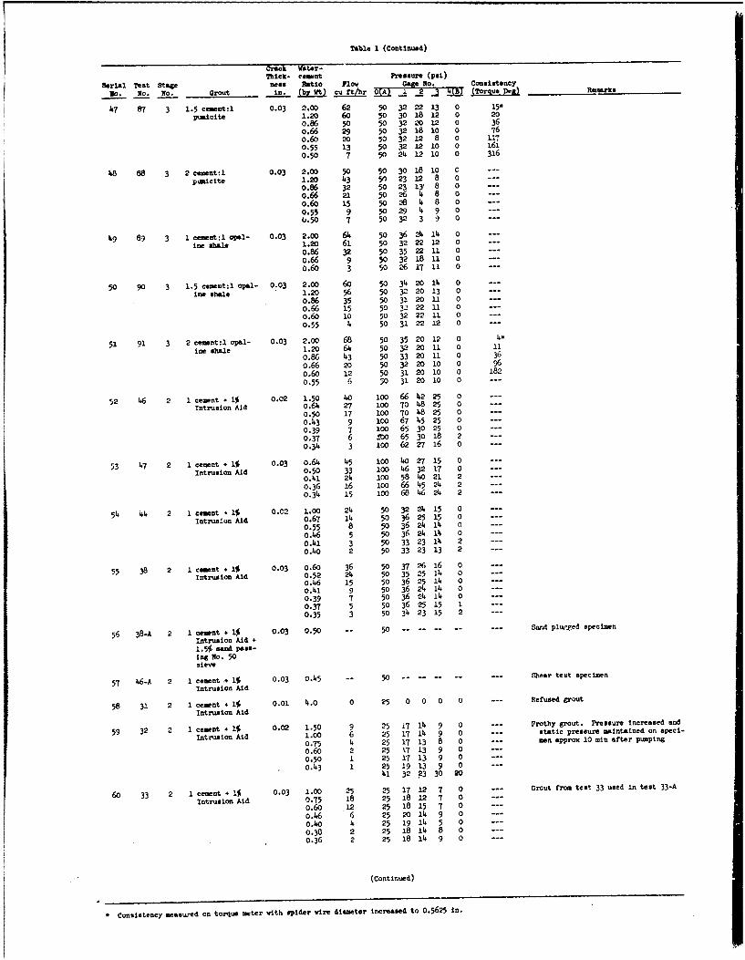
Table 1 (Continued)
Crack Water-Thick- eamant Pressure (pai)
Serial Test stage neas Ratlo Flowy j 2o3 Consistency
No0. No. No. Grout In. (by Wt) cu ft/hr PJA (T~orque ]*a) Rejearks
47 87 3 1.5 ceent:1 0.03 2.00 62 50 32 22 13 0 15"
pualcite 1.20 60 50 30 18 12 0 20
0.86 50 50 32 20 12 0 36
0.66 29 50 32 18 10 0 76o.60 20 50 32 12 8 0 117
0.55 13 50 32 12 10 0 161
0.50 7 50 24 12 10 0 316
48 88 3 2 cment:1 0.03 2.00 50 30 18 10 Cp,-,i ete 1.20 r3 5n 23 12 8 0 --0.86 32 50 23 1Y 8 0
0.66 21 5o 26 4 8 00.6o 15 50 28 4 8 0
0.55 9 50 29 14 9 0 ---
0.50 7 50 32 3 9 0 ---
49 89 3 1 cemnt:l OlI- 0.03 2.00 64 50 36 214 14 0
ieshale 1.20 61 50 32 22 12 0 ---
0.86 32 50 35 22 11 00.66 9 50 32 18 11 0
0.60 3 50 26 17 11 0 ---
50 90 3 1.5 cewent:1 opal- 0.03 2.00 60 50 34 20 14 0 ---
ine shale 1.20 56 50 32 20 13 0 ---
0.86 35 50 31 20 11 0 ---0.66 15 50 32 22 1 0 ---0.60 10 50 32 22 11 0 ---0.55 4 50 31 22 12 0 ...
51 91 3 2 cement:l opal- 0.03 2.00 68 50 35 20 12 0 4-
ine shale 1.20 64 50 32 20 11 0 11
0.86 43 50 33 20 11 0 36
0.66 20 50 32 20 10 0 96
0.60 12 50 31 20 10 0 182
0.55 6 50 31 20 10 0 ---
52 46 2 eement.+i 0.02 1.50 40 i00 66 42 25 0 ---
Intrusion Aid 0.64 27 100 70 48 25 0 ---
0.50 17 1oo 70 48 25 0 ---
0.43 9 oo 67 45 25 0 ---
0.39 7 1oo 65 30 25 0
0.37 6 rOO 65 30 18 2
0.34 3 100 62 27 16 0 ---
53 47 2 1 cement + 1$ 0.03 o.64 45 100 40 27 15 0
Intrusion Aid 0.50 33 100 46 32 17 00.141 214 100 58 40 21 2
0.36 16 loo 66 45 24 2 ---0.34 15 1oo 68 46 24 2 ---
54 1 2 I cement 41 0.C2 1.00 24 50 32 24 15 0
Intrusion Aid 0.67 14 50 36 25 15 0
0.55 8 50 36 24 114 0
o.46 5 50 36 24 114 0
0.41 3 50 33 23 14 2 ---
0.O 2 50 33 23 13 2 ---
55 38 2 1 emnt.1% 0.03 0.60 36 5o 37 ?6 16 0
Intrusion Aid 0.52 24 50 35 25 14 0
0.46 15 50 36 25 14 00.41 9 50 36 24 14 0
0.39 7 50 36 24 14 0 ---
0.37 5 50 36 25 15 1
0.35 3 50 34 23 15 2 ---
56 38-A 2 1 cement + 1% 0.03 0.50 50 ....- --- Sand plurxed specimen
Intrusion Aid -1.5$ san pass-ing No. 50sieve
57 46-A 2 1 cement .4 4% 0.03 0.45 50 . --- --- --- .. heer test specimen
Intrusion Aid
58 31 2 1 cement + 1$ 0.01 4.0 0 25 0 0 0 0 --- Refused grout
Intrusion Aid
59 32 2 1 cement + I% 0.02 1.50 9 25 17 14 9 0 --- Frothy gut. Pressure increased and
Intrusion Aid 1.00 6 25 17 14 9 0 --- static pressure maintained on spei-
0.75 4 25 17 13 8 0 --- men approx 10 sin after pumping
0.60 2 25 7 13 9 0 ---
0.50 1 25 17 13 9 0 ---
0.43 1 25 19 13 9 0 ---
41 32 23 30 20
60 33 2 1 cement + 1$ 0.03 1.00 25 25 17 12 7 0 --- Grout froa test 33 used in test 33-A
Intrusion Aid 0.75 18 25 18 12 7 0
0.60 12 25 18 15 7 0 ---
o.46 6 25 20 1 9 0
G.1O 4 25 19 14 5 0
0.30 2 25 18 14 8 0
0.36 2 25 18 11 9 0 ---
(Continued)
• Consistency measured on torque mrter with spider wire diameter increased to 0.5625 in.
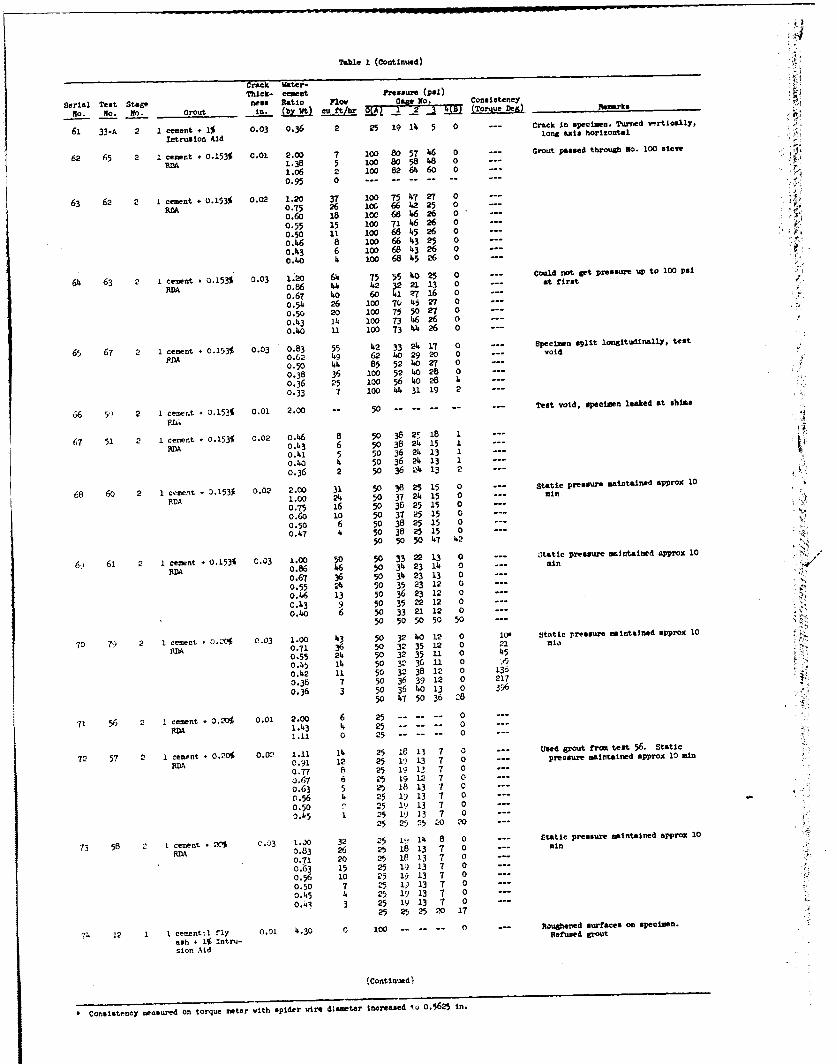
we1
Table 1 (Continued)
Crack Water-Thick- cment Pressure (psl)
Serial Test Stage nes Ratio Flo No. Consistency r
No. NO . Grout in. (by Wt) cu ft/r A (Torque Deg) Remark
61 33-A 2 1 cement + 1% 0.03 0.36 2 25 19 14 5 0 --- Crack In specimen. Turned vertiesllyp
Intrusion Aid long axis horizontal
62 65 2 1 cement 0.153% 0.01 2.00 7 100 80 5T 46 0 --- Grout passed through No. 100 sieve
RDA 1.38 5 100 80 58 28 01.06 2 1oo 82 64 60 00.95 .....
63 62 2 1Icement +0.153% 0.02 1.20 37 100 75 4.7 27 0
RDA 0.75 26 lor 662225 00.6o 18 100 68 4626 0
0.55 15 100 71 .6 26 0
0.50 11 100 66 15 26 0
0.46 8 100 66 13 25 0
0.43 6 lOO 66. 3 26 0
0.o 1, 1OO 68 1.5 26 0 ---
64 63 2 1 cement 0.153% 0.03 1.20 61 75 55 10 25 0 --- C t t res o
RDA 0.86 1. 12 32 21 13 0 --- atfirsto.67 40 6o 41 n 16 0
0.54 26 100 70 15 27 0
0.50 20 100 75 50 27 0o.4,3 14 100 73 16 26 0
0.40 100 73 4 26 0100
65 67 2 1 cement + 0.153f 0.03 0.83 55 12 33 21. 17 0 --- Specimen split longltuIAllYp, test
0.62 4,9 62 40 29 20 0 --- void
0.50 44 85 52 10 27 0
0.38 36 100 52 10 28 0
0.36 25 100 56 4o 28 1.
0.33 7 100 1. 33 19 2
66 5? 2 1 cement + 0.153% 0.02 2.00 -- 50 ------ -- Test void, specimen leaked at shims
RL;
67 51 2 1 cement + 0.153% 0.02 0.46 8 50 38 2! 18 1 --- 4
RA0.1.0 6 50 36 21. 13 1 -
o.2.i 5 50 36 2 13 1o.40 4 50 36 2 4 13 1 -- !
0.36 2 50 36 21 13 2 ---
18 60 2 1 cent 0.153k 0.02 2.00 31 50 38 25 15 0 Static pressure maintained approx 10
FDA 1.00 21 50 37 21 15 0 --- m'
0.75 16 50 36 25 15 0
0.60 10 50 37 25 15 0
0.50 6 50 38 25 15 0
0.47 1 50 38 25 15 050 50 50 1.7 1.2
69 61 2 1 cement 0 0.153% 0.03 1.00 50 50 33 22 13 0 --- static pressure mintained approx 10
RM 0.86 16 50 3 23 1. 0 --- r,
0.67 36 50 31 23 13 0
0.55 24 50 35 23 12 0
0.46 13 50 36 23 12 0
0.43 9 50 35 -2 12 0
0.O 6 50 33 21 12 050 50 50 50 50 ---
70 79) 2 1 cement .0.20% 03 1.00 43 50 32 10 32 0 10- Stutic pressure mintained approx 10 7?
BOA 0.71 36 50 32 35 12 0 21 mn
0.55 22 50 32 35 11 0 15
0.45 12 50 32 36 11 0 A.
0.22 11 50 32 38 12 0 136
0.38 7 50 36 39 12 0 217
0.36 3 50 36 20 13 0 39650 1.7 50 36 28
71 56 2 1 cement 0.20% 0.01 2.00 6 25-...... 0-"--
BOA .1.3 1 25- .....--- 0DA1.11 0 .....---- - 0
72 57 2 1 cement * 0.20% 0.02 1.11 12 25 18 13 7 0 --- Used grout from test 56. Static
0DA 0.91 12 25 1) 13 7 0 --- pressure maintained approx 10 ain
0.77 8 25 19 13 7 0
0.67 6 2 19 12 7 0
0.63 5 25 18 13 7 0c.56 4 25 19 13 7 0
0.50 - 25 19 13 7 0 -
0.1,5 1 25 19 13 7 0 ---
25 25 25 20 20 ---
73 58 2 1 cement 20% 0.03 1.30 32 25 1,? 12 8 0 --- static pressure maintained arprox 10
BDA 0.83 26 25 18 13 7 0 --- min
0.71 20 25 18 3 7 0
0.63 15 25 19 13 7 0
o.56 .0 25 19 13 7 0
0.50 7 25 19 13 7 0
0.25 1 25 19 13 7 0
0.4,3 3 25 19 13 7 0 ...
25 2 25 20 17
74 12 1 1 cement:l fly 0.01 4.30 0 100- - - - Roughened surfaces on specimen.
ash + 1% Intru- Refused grout
sion Aid
(Continued)
Consistency measured on torque meter with spider wire diameter increased tu 0.5625 in.
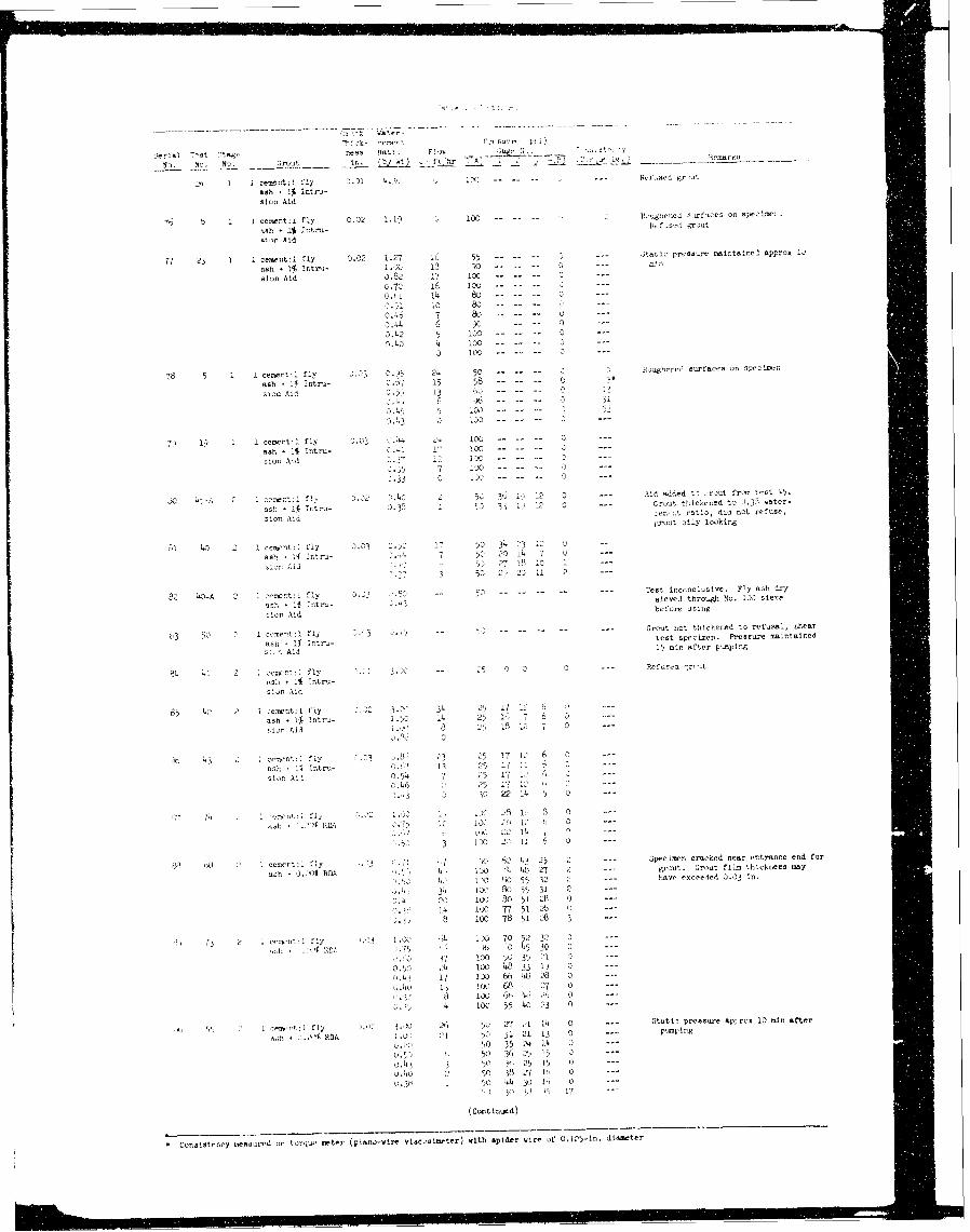
sra! 7-st ta+", nes0s 9a . Plus1~5 .. U eae ___
~Iu. No. o. ent ID. ft3 Fr CA J & L't
ash - I% intro-sion Aid
'6 1 ce.,ent:1I fly 0.02 1.1) 100 -P oduuse rset
ash -% I$ttrU- R.4.. >) .3voi t
si',f Aid
7I 23 1 1 censntI 1 ly 0.32 1.27 i6 55 ;itico pressure naintalnel appros 1,)
ash +1{lintni- 1.4 13 A 0 - z-- tn
asio Aid 3).82 17 1000.73 16 I0 - --l
IsO' 14 6G-
04. 6 90 -- 30.42 5 130 -___ _ 0 --
o.o 4 100 3 -
78 5 1 1 centnt:1I fly '5 24 50-Buyeldsrasorsect:ash + .1 I-ntru- 0." 15 58 - 0 7
a10111 7I~ 13 '0
7;, 09 1 1 cemnt: fly 21 ' '4 10--------0 --
ash ilk Intro- 1-1117
5 ------------
4l15-A 2 1 ee-olfly Y.c z 5 3'; 1) 11 2 --- Alid aided t- .-cout from test 45.
ash~~~~~ - IAItr-3 01 0 -- cst thickened to .. 8water-
asun ,t - 8 Aid -. : :. ratlo, did sot refuse,sijn id i4rout oily looking
Si 43 2 lecnt:1fly 03 w 1 50 3413912 0
assl - A ttru- 5 20 14 7 0
rsn A11.1 27, 18 >3 I1 -
'.o-7 53 2, '- 11 ---
32 40-A 2 1 zent:~ fly J.2 <.5c --- Test inoonclustve Fly as dry
'itt . 1 ttru- . ievel through No.130 sieve'Ich if Itra-before using
niun Aid
63 50 2 1mcement :1fly 3 V <.4 - 52 - - ---- Grout not thickened to refusal, shear
aol;- 1 Iztxs-test specimni. Pressure Maintainedas" Ai t 15, mIn after pomplog
81 . 2 lcmr:fly ' 3 - 5 j 3 -- hfuoeu .mut
,ah . it, ltr-
35 42 2 ceetttr.l fly 9. 3 3. 34 2 5 It 1 6-sh j 1% ntru 1.52 14 2% 1" 7
stun Aid 8s 38 2' 32i, 7563 0
3in 43 11 lc 1e fly .3 38 3 25 7(1'aoh-lS Intru- 3. 13 2-5 11
tin Ali (,.,4 7 2 17 12 0o.46 2 25 1' 1 0
.>'7 lor nt~i~ V'-3 14.3>'SO 5 0
3 1 . 6 0
PO -2Tt> fly 1 7 e36 , . 2 --- Specimen cracked sear entrance end for
ash 0_Q.41 RDAh 4, F4 7 t' 3 23 goi~t. Grout film thickness5 may
4;, IP711 55 32 2 --- have exceeded 3.33 in.
"4 34 1>' B 855 3t1I.4' 21) 100 30351 "iS --
o'1 h 1, 100' 77 51 2b.J 5 100O 78 51 28 3 ..
1>~ oci:fly e'), !> ~ 00 70 52 32 0.30 10 ' o 3 45 30 0
!7li) 53 35 21' 0 ..
35' 1. CI) 483 33 1') 3t7 t2L> (Y 6 1> 43 238
u4 i ,(x) 68 -i 3
~, 4 100 55 40 : 3 0
K) S * Y) 'ensor:) fly 1 . 3 26 ' , r7 ,1 14 0 .. Stati- prvosw-e app-ox 10 min after
su..\ROA JG; 21 50 u 21 13 0 -- pumpingu.("' 9 35 24 14 3) --
0. ) 53 363 5 1$ 0 ..
o. 43 3 50 4' 5 P) () --J.40o : 1' (3 18i L7 LI, 0 --
0.3 - 59 i> 4 to 0o -
(Cuntinued)
*Conals~teiwy neanired on to)r~js' urter (piano-wire viseostwier) with spider wire of 0.125-in. diawtef
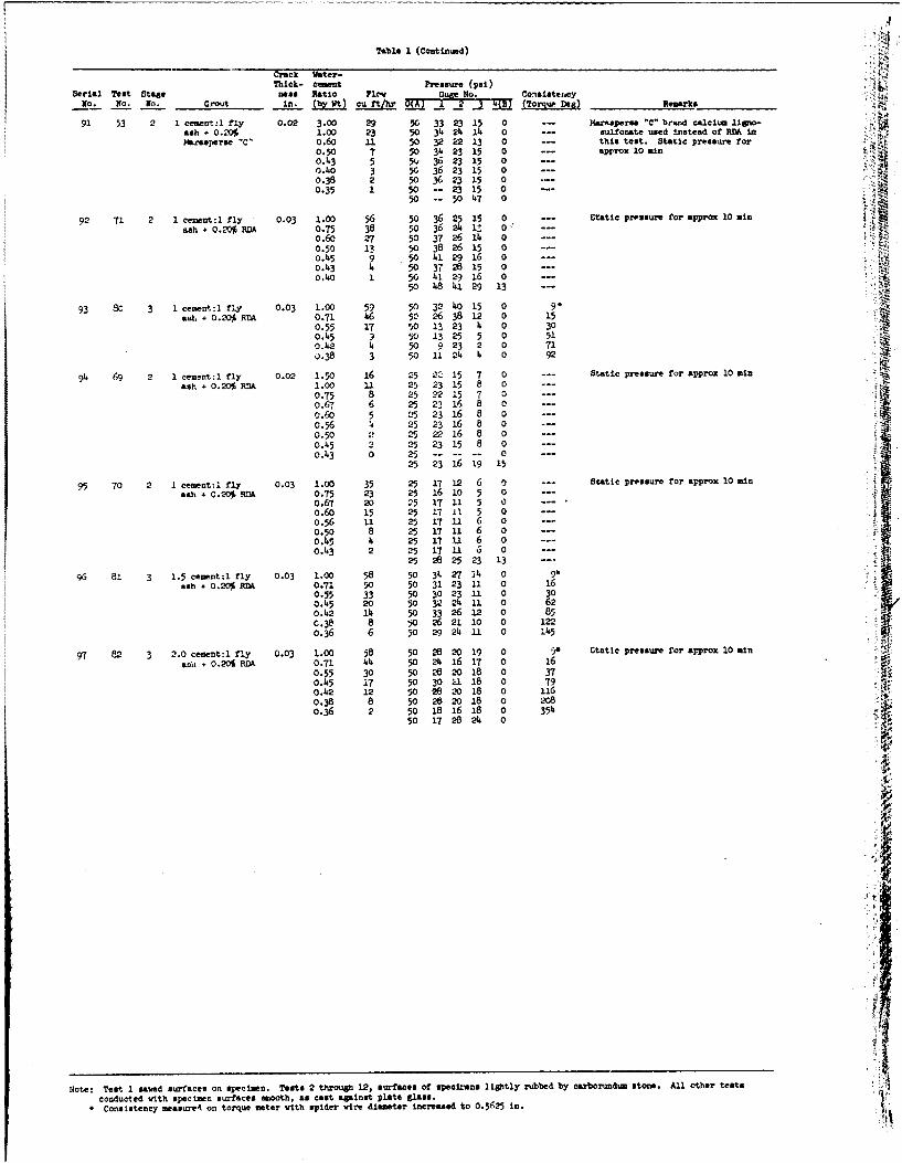
A
Table I (Continued)
Crack Water-Thick- cemt Pressure (psi)
Serial Test Stage Dos Ratio FlewGu6e No. Consistezuey
No. NO. NO. 4(B)n. {~ cif/h __ (Torque Deg) Remarks
91 53 2 1 cement:l fly 0.02 3.00 29 50 33 23 15 0 Marasperse "C" brand calcium ligno-ash + 0.20% 1.00 23 50 34 24 14 0 sulfonate used instead of RDA In
W4rasperse "C' 0.60 11 50 32 22 13 0 --- this test. Static pressure for0.50 7 50 34 23 15 --- approx 10 mino.43 5 5v 36 231 5 0 =-0).40 3 50 36 23 15 00.38 2 50 36 23 15 00.35 1 50 -- 2315 0 ..
5o -- 50 47 0
92 71 2 1 cem t:l fly 0.03 1.00 56 50 36 25 15 0 --- ,tatic pressure for app o 10ash 0.2*RDA 0.75 38 50 36 24 1, 0
0.6o 27 50 37 26 14 0 ---0.50 13 50 38 26 15 --o.45 9 50 41 29 16 0o.43 4 50 372 1 5 0 Vo.4o 1 50 41 29 16 0 §
50 48 9412 3 ---
93 80 3 1 cementl fly 0.03 1.00 59 5o 32 414 15 0 9"ash 0.20% RDA 0.71 46 50 26 38 12 0 15
0.55 17 50 13 23 4 0 30
0.45 50 13 25 5 0 51o.42 4 50 923 2 0 710.38 3 50 11 24 4 0 92
94 69 2 1 cemnt:l fly 0.02 1.50 16 25 2- 15 7 0 --- Static pressure for approx 10 minash 0.20 RDA 1.00 11 25 23 15 8 0
0.75 8 25 22 15 7 00.67 6 25 2316 8 00.6 5 25 23 16 8 ---0.56 4 25 2316 8 00.50 25 22 16 8 0 ---0.45 2 25 2315 8 00.43 0 25 -------- 0
25 23 16 19 15
95 70 2 1 cement:l fly 0.03 1.00 35 25 17 12 6 0 --- Static pressure for approx 10 min
ash + 0.20 RItA 0.75 23 25 16 10 5 0 -V0.67 20 25 17 11 5 0 .0.60 15 25 17 11 5 0o.56 11 25 17 11 6 00.50 8 25 17 11 6 0o.45 4 25 17 U 6 0o.43 2 25 1711 S 0
25 26 25 23 13 ....
96 81 3 1.5 cementt1 fly 0.03 1.00 58 50 3k. 27 14 0 9Aash 0.20 RDA 0.71 50 50 31 23 11 0 16
0.55 33 50 30 23 U1 0 300.45 20 50 32 24 11 0 620.42 14 50 33 26 12 0 85C.3q 8 5o 26 21 10 0 1220.36 6 50 29 24 11 0 145
97 82 3 2.0 cement:l fly 0.03 1.00 58 50 26 20 19 0 9* Utntic pressure for approx 10 minsoil + 0.20% POA 0.71 44 5o 24 A1 17 0 16
0.55 30 50 -8 20 18 0 37
0.45 17 50 30 U 18 0 790.142 12 50 26 X0 L8 0 1160.3 8 50 26 20 18 0 2080. 2 50 18 1618 0 354
50 17 28 24 0
Note: Test 1 saved surfaces on specimen. Tests 2 through 12, surfaces of speci" as lightly rubbed by carborund-n stone. All other tests
conducted vith specimen surfaces olooth, as cast against plate glass.* Consistency meaause4 on torque meter vith spider vire diameter increased to 0.5(25 in.
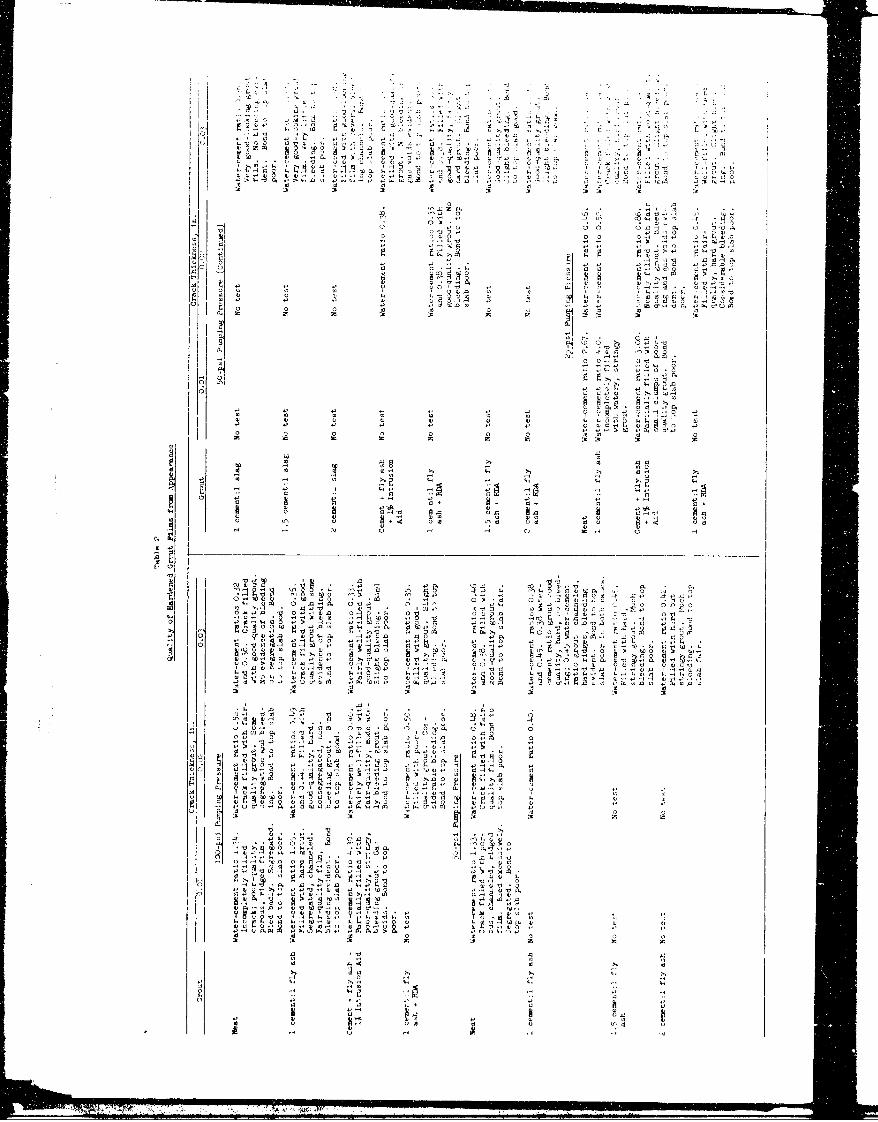
Ao V
Ao '.3 A
-II
II E ~ ~ F C ~ i 4->, F"'PO, tI Aloll
41 a'A Id I'd"O
'I C~ -A -~-93(3 A o vc I
F F FC,
I) ~ ~ ~ ~ 4 A oAA IAfA Siis 4 S. A isS. S 'I'
Al4. 0
o A, oii A
is o0 w 0 o3-I)j isA Is S'Ii A i13 31 ii4 o' A i .
15 P.
'd 1 , o 10 x
is 0is Aisi -~ H.2 ~ ~ I M s .i ~ iQ .I s .
5' CA A C
-l A 9w k 'D'os .4
- is '
m340
H, ~ ~ ~ ~ ~ ~ ~ ~ ~ ~ ~ ~ ~~~~I d__ _ _ _ _ _ _ _ _ _ _ _ _ _ _ _ _ _ _ _ _ _ _ _ _ _ _ _ _ _ _ _
F, (0
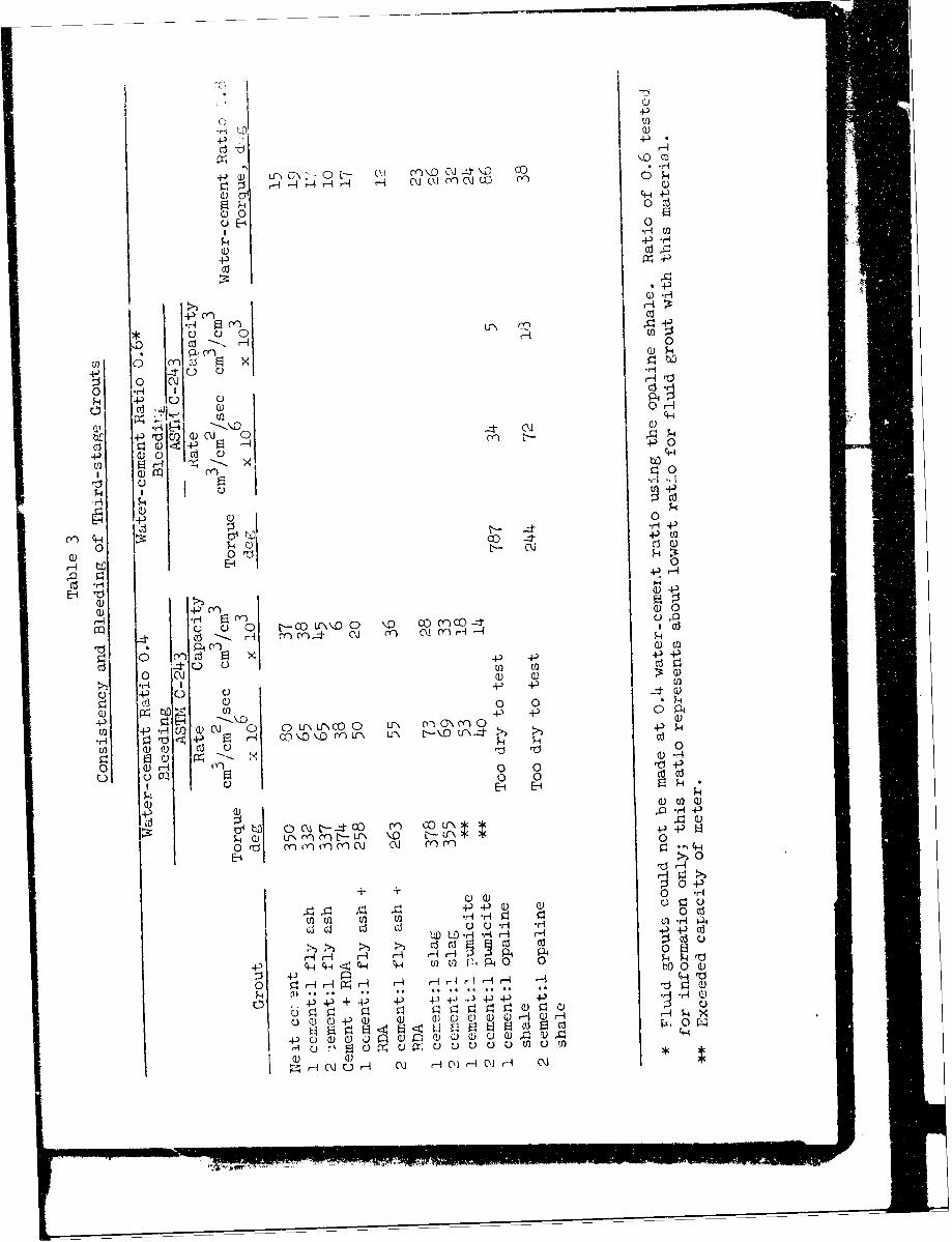
.p~
dd
+20) i'. \-O I - 4 C.' C~j (Y C\j1 cc Cr
0 0
O4-)
Q ) -H
4. (Y)
0 x
0 C ) r-4 0
rd0 -P 0 PH
8~ 4C)
I Q)
0)i r4 L *3\ Cc.
(Y' 0)) u~ CC) 4- O
) 0H Z c ~C)I ldI P0
Cc)
Q))
OL aC 0~+U
H iC H .
H) --I C*P ,j (Y l -
0 ) ~
z ~ -0 0)
C)) C) 0B 4-;'~f\D 00 PC
4- 0 a)-
0n C')C 0Ud
oo c'.0C)~ ~~ .,4C)42 2U
0 (D r () 0 0O4-+2 P ~ .'
4-0)) 0~
C)i 4- H
(a) Lr Q)
O- 0) '1) 0) 0 0
+ +) 0 -
Ua))4-) 0)
0 a
bD~ 0CLDz 4-) CdU
F.,~b 0) LfYL)-f\
4- A 2420 a
4-) 4) + 4) 4-) 4-4--0 4) - -)ri
0C))r A ++
m C) C C-) C) C)~,4 C) bO ' 0
;:i 4.)r N r ~
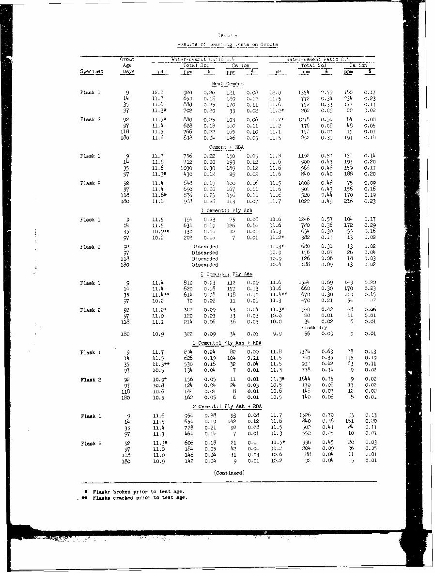
, 'esalfs of* ,uc nl, 'e st on Grouts
Grout Water-cec;,t t'ci'o -. 4 4ater-cenerlt Fatlo 0.',Age Total Sol Ca ion Total C] Ca or.
S pec Imen DRays ME pp 31p- m7Neat Cement
Flask 1 9 12.0 920 0.26 121 0.o8 12.u 1354 '-59 180 0.1714 11.7 65a 0.18 189 0.12 11.5 772 0.34 134 C. 2335 11.6 888 0.,25 10 0.11 11.6 752 0.j3 177 0.17
97 11.3* 702 0.20 33 0.02 11.2* )C0<) 0.09 22 0.02
Flask 2 92 11.5* 880 0.25 103 o.o6 11.7* 1278 0.56 84 0.08
97 11.4 628 0.18 O60 0.11 11 . 2 176 0. 08 48 0.05118 11.5 766 0.22 165 0.10 11.1 152 0. 07 15 0.01180 11.6 838 0.24 146 0.09 11.5 89)2 0.3) 191 0.18
Cement + RDA
Flask 1 9 11.7 756 0.22 150 0.09 11.8 1192 0.57 137 n.1414 11.6 712 0.20 193 0.12 11.6 900 0,43 193 0.2035 11.6 1030 0.30 189 0.12 11.6 966 0.46 159 0.1797 11.3" 430 0.12 29 0.02 11.6 840 0.40 188 0.20
Flask 2 92 11.4 648 O.19 100 O.06 11.5 1008 o.48 75 0.0997 11.4 69o 0.20 167 0.1i 11.6 901 0.43 156 o.16
118 11.6* 876 0.25 156 0.10 11.6 920 0.44 170 0.19
180 11.6 988 0.28 113 0.07 11.7 1022 j.49 216 0.23
1 Cemrent:l FIXAch
Flask 1 9 11.5 794 0.23 75 0. 02 11.6 1246 0.57 1O4 0.1714 11.5 634 o.19 126 o.14 11.6 780 0.36 172 0.29
35 1. 130 o.04 12 0.01 11.3 654 0. 30 95 n.16
97 10.2 202 0. o 7 0.01 11.2* 382 0.1' 13 0.02
Flask 2 92 Discarded 11.3* 680 0.31 13 0.0297 Discarded 10.9 156 0.07 26 0.04118 Discarded 10.9 126 ).o6 18 0.03180 Discarded 10.4 188 0.09 13 0,02
":'2 C__enpii., FlyAsr,
Flask 1 9 11.4 810 0.23 112 0.09 11.6 1524 0.69 149 0.2014 !1.4 620 o.18 157 0.13 11.6 66o 0.30 170 0.2335 11.4* 614 0.18 I18 0.10 11.4** 670 0.30 110 0.1597 10.2 70 0.02 11 0.01 11.3 470 0.21 54 - 7
Flask 2 92 11.2* 302 0.09 43 0.04 11.3* 940 0.42 48 0.97 11.0 120 0.03 33 0.03 10.0 20 0.01 11 0.01118 ii.1 214 .06 36 0.03 10.0 34 0.02 8 0.01
Flask dry
180 10.9 322 0.09 34 0.03 9.9 56 0.03 9 0.01
1 Cement:l F Ash + RDA
Flask 1 9 11.7 8)4 0.24 82 0.09 11.8 1374 0.63 78 O.i314 11.5 626 0.19 104 0.II 11.5 760 0.35 115 0.1935 11.3- 530 0.16 32 0.04 11.5 93' 0.42 63 0.11
10.5 134 0.04 7 0.01 11.3 738 0.34 9 0.02
Flask 2 92 10.9* 156 0.05 11 0.01 11.3* 1644 0.75 9 0.0297 10.8 124 O.04 24 0.03 10.5 130 0.06 13 0.02
118 io.6 141 0.04 8 0.01 10.6 0 0.07 12 0.02180 10.5 162 0.05 6 0.0i 10.5 14o o.o6 8 O.O
2 Cement:1 FIl Ash RDA
Flask 1 9 11.6 954 0.28 93 0.08 11.7 1526 0.70 A 0.1314 11.5 654 o.19 142 0.12 i1.6 84o 0.38 151 0.20
35 11.4 728 0.21 92 0.08 11.5 902 0.41 4 o.ii
T 11.3 464 0.14 7 0.01 11.3 552 o.25 10 o.01
Flask 2 92 11.3* 606 o.18 21 0. ... 11.5* 996 0.45 20 0.0397 11.0 184 0.05 42 0.04 11.. o4 0.09 36 0.5118 11.0 148 o.om4 31 0.03 i0.6 88 o.4 11 o.oi180 10.9 142 0.04 9 0.01 10.2 y2' .04 5 0.01
(Continued)
* Flaskr broken prior to test age.** Flasks cracked prbor to test age.
,,iC
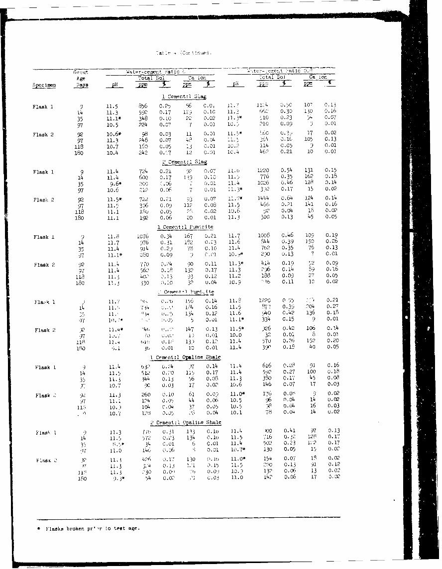
("rout WaL.r-ceient 2atio 3, w ',e't >atic 0.7
Age Total Sol Ca ion :otal Sol Ca ion
Specimn Days PE.. pp na PHi pp" J-i mIi
1 Cement:l SIa
Flask 1 9 11.5 856 0.25 56 O.O 11.7 llC0 0.50 107 0.1314 11.3 592 0.17 12) 0.10 11.3 16 0.30 130 0.16
35 11.1* 348 0.Io 22 0.02 11.3* 510 0.23 54 0.07
97 10.5 224 0.07 7 0.01 10.5 210 0.09 9 0.01
Flask 2 92 10.6* 98 0.03 11 0.01 11.5* £60 O.3- 17 0.02
97 11.3 248 0,07 49 0.04 11. 5 36'i .1 105 0.13
118 10.7 160 0.05 13 0.01 10.2 114 0.05 9 0.01
180 10.4 242 0.37 12 0.01 10.4 462 0.21 10 0.0
2 Cement:I Slag
Flask 1 9 11.4 724 0.21 92 0.07 ii.o 1220 0.54 131 0.15
14 11.4 600 0.17 139 O.ic 11.5 776 0.35 162 0.18
35 9.6* 200 -. 06 0.01 11.4 1026 o.46 128 o.14
97 10.6 212 0.06 7 0.01 11.3* 3)2 0.17 15 0.02
Flask 2 92 11.5* 722 0.21 93 0.07 11.7* 1444 0.64 124 0.14
97 11.5 306 0.09 112 0.08 11.5 466 0.21 141 0.16
118 11.1 11u 0.05 2, 0.02 10.6 92 0.04 18 0.02
180 i.1 192 0.06 20 0.01 11.3 300 0.13 45 0.05
1 Cement:l Puimlcite
Flask 1 9 11.8 1076 0.34 167 0.21 11.7 1008 0.46 109 0.19
14 11.7 976 0.31 182 0.23 11.6 804 0.39 150 0.26
35 11.4 914 0.2) 78 0.10 11.4 762 0.35 76 0.13
97 11.1* 280 0.09 ) 0.01 1O. 290 O.13 7 0.01
Flask 2 92 11.4 770 0.24 90 0.11 11.3* 414 0.19 ,52 0.0
97 11.4 562? 0.18 132 0.17 11.3 296 0.14 89 0.16
118 11.3 4o2 0.13 )3 0.12 11.2 18 0.09 27 0.05180 11.3 330 0.10 32 0.04 10.9 '>3b 0.11 10 0.02
Fla.-k 1 11.7 "t 0..u 156 o.14 iI.S 1220 0 55 '. 0.21
14 11.1, 1. o,,': iiO o.16 11.5 872 0.3) 204 0.27,5 134 0.12 11.6 940 0.42 136 0.18
97 10. . Y.05 5 O.01 11.1* 334 0.15 9 0.01
Flask 2 )2 11.'.* 14n .') 147 0.13 11.5* )26 0.42 106 O.i497 )u.7 ' u.O 1 0.01 10.0 32 O.0i 8 0.O1118 11.4 (,Ih 0. 12 13) 0. 1 11.4 57U 0.26 152 0.20
180 ,.1 jj 0.01 10 0.01 11.4 39" 0.1 40 0.05
1 Cemnt:l Opaline Shale
Flask 1 9 11.4 632 o.24 -r 0.14 11.4 616 0.25 9] o.16
14 11.5 512 0.20 11 0.17 11.4 592 0.27 100 0.1835 11.3 j44 0.13 56 0.08 11.3 380 0.17 45 O.O8
97 1O.7 90 0.03 17 0.02 10.6 146 0.07 17 0.03
Flask 2 52 11.3 260 0.10 61 0. o) II. o * 176 0. OH 9 0.02
11.1 124 01).05 44 0. 06 10.5 96 n~o4 14 o.02
113 10.) 104 0.04 37 0.05 10.5 yl 0.04 16 0.03- 10.7 12 O.05 :8 0.04 10.1 78 o. 04 14 O.02
2 Cement: I Opaline Shale
Flask 1 9 11.3 T70t 0.31 133 0. lu 11.4 )00 0.41 SP 013
14 11.5 512 0.23 134 0.lo 11.5 716 0.32 121 O. 17
35 t). * 34 0.01 6 O.O1 11.4 502 0.23 122 0.17
07 11.0 146 0. c6 9 0.01 10.7* 130 0.05 15 0.02
4ia 2 2 11.3 426 0.17 130 0.1b 11.0* 154 0.07 1 0.0211 I .3 3 ,'4 0.13 I'll o. 15 11. 5 2810 O.1 4 1 0. 12
115 11.3 .30 O.01 o 0.0? 10.) 13? 0.06 13 0.02
180 9.3* 54 0.02 21 0.03 11.0 142 0.06 17 0.02
* Flasks broken pr'-r to test age.
Li.. ..... q1
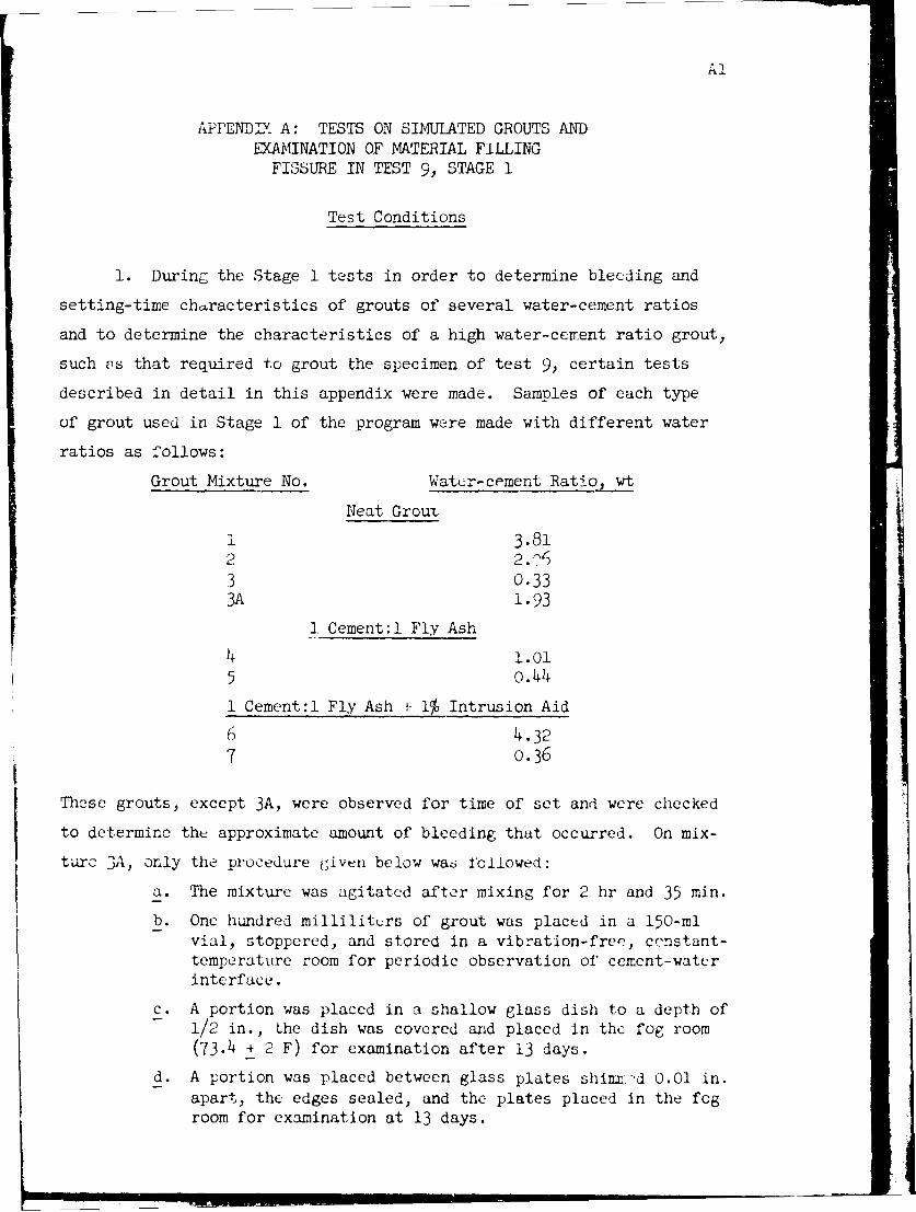
Al
APPENDIX A: TESTS ON SIMULATED GROUTS ANDEXAMINATION OF MATERIAL FILLING
FISSURE IN TEST 9, STAGE 1
Test Conditions
1. During the Stage 1 tests in order to determine bleeding and
setting-time characteristics of grouts of several water-cement ratios
and to determine the characteristics of a high water-cement ratio grout,
such vs that required to grout the specimen of test 9, certain tests
described in detail in this appendix were made. Samples of each type
of grout used in Stage 1 of the program were made with different water
ratios as follows:
Grout Mixture No. Watcr-cement Ratio wt
Neat Grout
1 3.812 2.3 0.333A 1.93
1 Cement:1 Fly Ash
5 o.44
1 Cement:l Fly Ash , 1% Intrusion Aid6 4.32
7 0.36
These grouts, except 3A, were observed for time of set and were checked
to determine the approximate amount of bleeding that occurred. On mix-
n, oly the procedure given below wa6 roliowed:
a. The mixture was agitated after mixing for 2 hr and 35 min.
b. One hundred milliliters of grout was placed in a 150-mlvial, stoppered, and stored in a vibration-free, constant-temperature room for periodic observation of cement-waterinterface.
c. A portion was placed in a shallow glass dish to a depth of- 1/2 in., the dish was covered and placed in the fog room
(73.4 + 2 F) for examination after 13 days.
d. A portion was placed between glass plates shinx-d 0.01 in.apart, the edges sealed, and the plates placed in the fogroom for examination at 13 days.

A2
e. Additional Portions were placed in foul, sL~all stopperedvials, stored in the fog room, and examined at 1, 3, 7;and 13 days.
Time of Set
2. The time-of-set tests wure made using the Vicat time-of-set
needle (1-xram diame~er) with the grout contained in 130-mi, wide-mouthed
bottles approximately 1.75 in. in diameter by 3.06' in. high. Mcasure-
inents were m~.ie for depth of penetration below the cement-water interface.
The grout conditions tested and setting times obtained are shown in the
following tabulation. The setting-time results are plotted on fig. Al.
80
- ----- A NE AT I EMEN-4T W/C .3 5! By kI: H
0~ -- O NEAT CEMENT W/C 2 06 B WEIGHT. L
0 ----- 0 NE AT C EME NT W/C 033 By WFtCHT
-44 A.I . . - I CEMENT IFLY' ASH W/C 1 01 BY
- +-+ [CEMENTl I LY A.SH WIC 044 B1. WE IG H TI0 CEMENT I FLY A&m Pt.u5 1% AI
*": 4 32 0YWCiG
CE EN I L % LU ".4so m - EET IFYA94"L>.DW/C 0 38 By WEIGHT. -'
4 '
20
ie 8 S4 32 40 48 5
Fig. Al. Settin~;tI- of g.routs
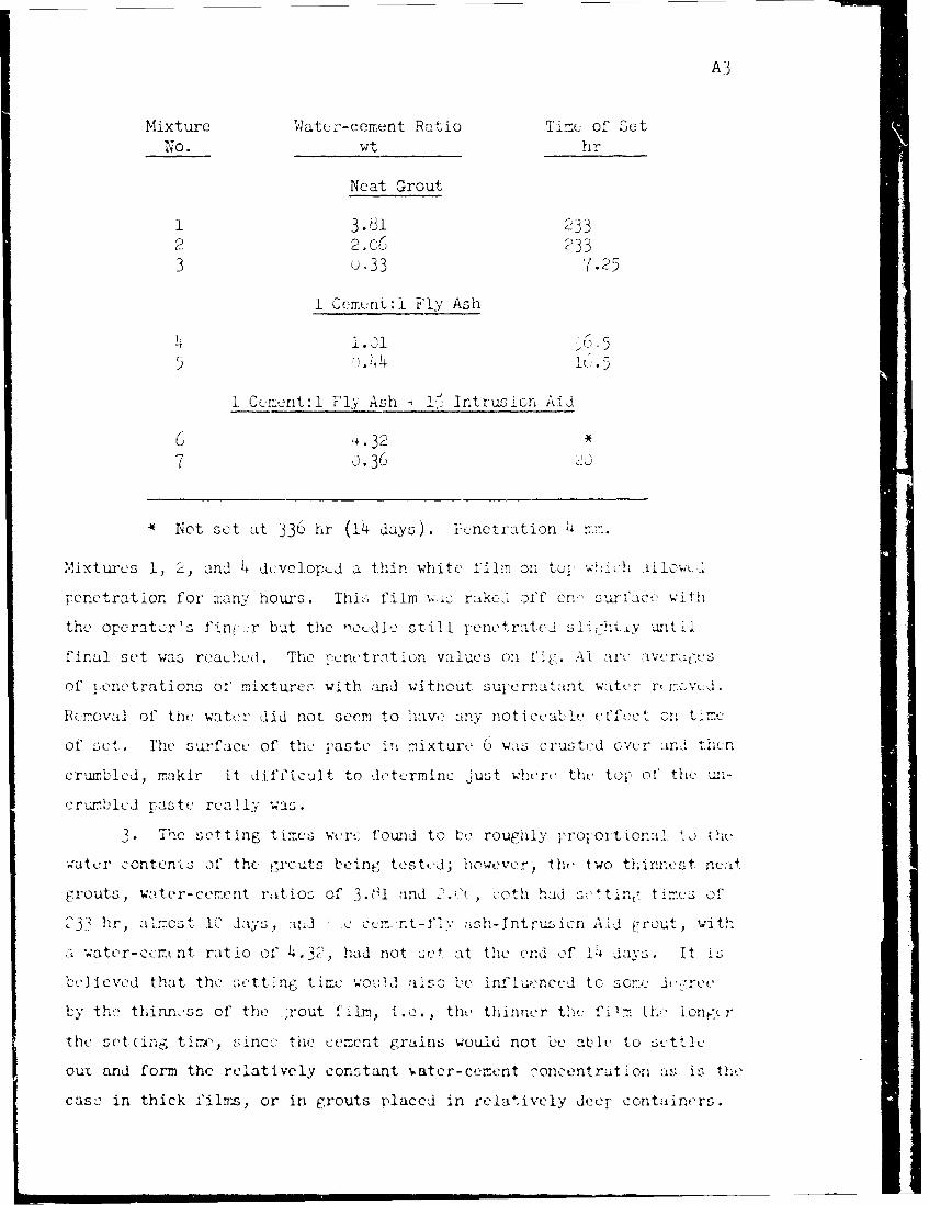
A3
Mixture Watci-cemunt Ratio Time: of 'OctNo. Wt hr
Neat Grout
1 3.81 2332 2.06 2333 u-33 Y7.2 5
1 Ccmtent:i Fly Ash
14.14 ]aj . 5
1 CcYment:1 Fl.- Ash -4 1" Intrus3ion, Aid
U 4.32*
7 3 .36 i
*Not set at 336 hr (14 days). Penetration 4 r~
Mixtures 1, 2, and 4 dcvciop _d a thin white f'ilmn on to,.wi% ilowt_,
penetration for mran'; hours. Thi,. film w,:,: rake , off cr- surt'ji- wi
the operator's fini. r but the "oudic2 still 1penetrate i .:lI unltil
final set wa3 reached ,. The -!enctrcition values on .Alt ai% Lvcra,e -
of i~crnetrations olf mixturc- wiLth and without. s.u &rlat tnt water rexd
Removal Of the! water dlid not seem to h.ave any rloti~ ce effec-t on time
Of set,. Fh'e sur-faCe Of theL IraSte i'i ::ixture. 6' wsCrusted over aIna 3e
crunrbled, makir it difficult to dete-rmine just whiere the top, of the: uin-
crur 'le1 d paste really' was.
-c~ seCting Iimcs wereCfor to tcroucr-iily
watcr ,onten:Lz of' the. 1,rcuts tein, testc'd; 'however, theif two thinnest nu:O.t
crouts, water-cemenit rttios3 of 3>1,i ind 'oth Lid se n.tlie f
233 r ~~.1 Jays, :ted .e e<nt1v2Inr~c A Id rout , wit.!
awater-eem(nit raitio of 43,had niot oat the nid of ldays. It
believed that the settine, time ',.,alo c influ,.-nccd to soejf-rvu
11-Y th- th~inne ss of th~e rout fliLm, i .c. th'' thinner theC fiI- thelon;-
the setcing tire, since_. the cement Crains wuu:d not lbe anble to stl
out and form the relatively constant -ater-cenent -oncentrution as is the_
case, in thick filrz, or in grouts p~laced in relatively deer- containers.
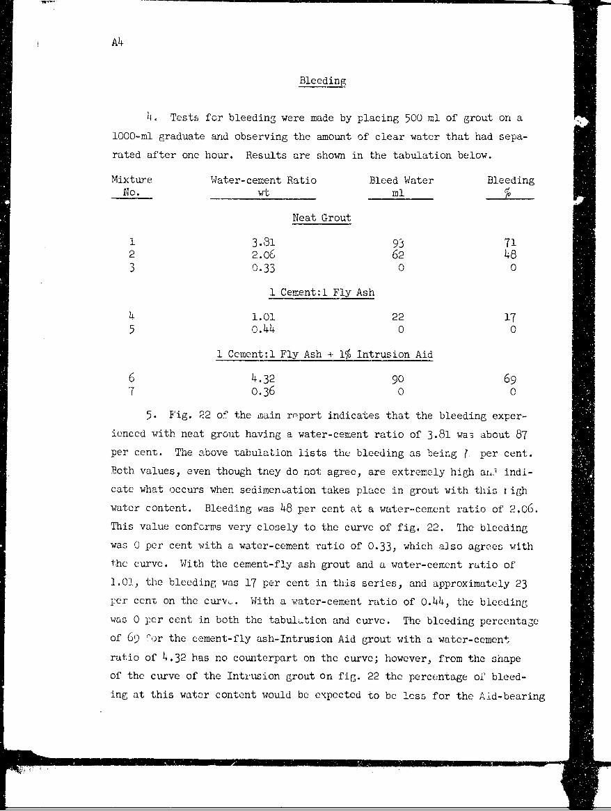
A4
Bleeding
4. Tests for bleeding were made by placing 500 ml of grout on a
1000-ml graduate and observing the amount of clear water that had sepa-
rated after one hour. Results are shown in the tabulation below.
Mixture Water-cement Ratio Bleed Water BleedingNo. wt ml
Neat Grout
1 3.81 93 712 2.06 62 483 0.33 0 0
1 Cement:l Fly Ash
4 1.0l 22 175 o.44 0 0
i Cement:l Fly Ash + 1% Intrusion Aid
6 4.32 90 697 0.36 0 0
5. Fig. 22 of the main report indicates that the bleeding exper-
ienced with neat grout having a water-cement ratio of 3.81 wa3 about 87
per cent. The above tabulation lists the bleeding as being ( per cent.
Both values, even though they do not agree, are extremely high al,' indi-
cate what occurs when sedimentation takes place in grout with this figh
water content. Bleeding was 48 per cent at a water-cemcnt ratio of 2.06.
This value conforms very closely to the curve of fig. 22. The bleeding
was 0 per cent with a water-cement ratio of 0.33, which also agrees with
the curve. With the cement-fly ash grout and a water-cement ratio of
1.01, the bleeding was 17 per cent in this series, and approximately 23
per cent on the curvy. With a water-cement ratio of 0.44, the bleeding
was 0 per cent in both the tabul-tion and curve. The bleeding percentage
of 69 Oor the cement-fly ash-Intrusion Aid grout with a water-cement
ratio of 4.32 has no counterpart on the curve; however, from the shape
of the cirve of the Intrusion grout on fig. 22 the percentage of bleed-
ing at this water content would be expected to be less for the Aid-bearing
A5
grout than for neat grout. No bleeding was indicated either in the
tabulation or on the curve for cement-fly ash Tntrusion Aid grout at a
water-cement ratio of 0.36.
Petrographic Examination of Specimensof Grout Mixture 3A at 13 Days
6. The rradua- e, mold, and shimned g ass plates were inspected
before they were opene d. The supernatant water in the graduate was clear,
but a thick film of white to grayish scum floated on the surface of the
water. A large -umbor of small wter-clear crystals were attached to the
inner wall of +he graduate between the cement-watcr interf"ace and the
surface of the water. S3imilar crystals could be seen on the upper sur-
face of the grout.
7. The shimme. glass plates were examined through the upper plate,
using a stereoscopic microscope. There were many crystals adhering to
the upper plate, in interfering masses. in some, the broad flat hexag-
onal shape of Ca(Oi)2 was clearly visible. Some air bubbles had been
caught between the plates in the preparation of the specimnen. The tops
of the bubbles were separated from the upper glass by a thin film of
solid material which did not contain any crystals large enough to be
recognized with a stereoscopic microscope. Some subsidence or shrinkage
of the grout film appeared to have taken place. When the shimmed glass
plates were separated, the grout film stuck to the lowei plate, and the
hydroxide crystals to the upper. The grout could be scratched with a
fingernail, was coherent, and looked like an aggrerate of fine grains of
silt size. The Pyrex mold was tilted while being moved from the fog
room to the stereoscopic microscope room, and ioose material on top of
the grout was agitated so that the supernatant water was slightly turbid.
Some crystals of calcium hydroxide could be seen on the upper surface of
the grout.
8. The supernatant water in the small scaled vial had a thick film
in the meniscus, and hydroxide crystals were adhering to the glass and
lying on the upper surface of the grout. Since the vial appeared similar
7,l ,i .l ... i _

A6
to the graduate and the Pyrex mold, it was decided that a petrographic
examination would be made of the sealed vial, and a chemical analysis of
the other specimens.
Results of Exanination of Bleed Water and Paste
9. The results of the examinations at 1, 3, 8, and 13 days are
reported in table AI, and can be summarized as follows:
"e At, 3, 8, and 13 days the unhydrated portions of the ce-ment, calcium -Vdroxi.de, and calcium carbonate were theonly crystalline constituents detected in the bleed waterand the paste.
b. At all. ages., amorphous gel formed by hydration could befound as rlms around unhy.rated cores. The gel carbonatedvery quickly when air had had access, developing smallsphexrulites and incomplete spherulites of calciumcarbonate.
c. Only one crystal fcrm of calciim hyaroxide' was found; ahexagonal pla:., bounded by the hexagonal prism (or twotrigonal prisms) and basal pinacoid; (fig, A2). Group;
Fig. A2. Calcium hydroxide crystal from bleed water, Xll0, plane light.A thin film of carbonating gel overlies and surrounds the crystal, andclumps of carbonating gel and unhydrated cement are scattered throughthe field. The diameter of the crystal as mea3ured in the A-B directionwas 0.20 rrm. The crystal has the forms co.non in calcium hydroxide -
the pinacoid and prism
777
A7
formed by the intergrowth of several plates increased insize, number, and complexity with increasing age. Thesize of the single crystals also increased with age. Someof the single crystals and some of the members of the groupsshowed variations in extinction pusition; a few of the in-terference figures obtained were biaxial with a very smalloptic angle but more were uniaxial negative. Where thediameter and thickness of the same crystal could be meas-ured, the diameter was about 10 times the thickness oncrystals about 0.2-0.3 mm in maximum diameter.
d. No calcium sulfoaluminate was found in any of the freshlyprepared immersion mounts at 1, 3, 8, or 13 days. The highsulfate form was found in unsealed slides of bleed waterfrom the 13-day vial, after the slides had been allowed toevaporate for several days. The high sulfate form occurredas prisms and needles with parallel extinction, negativeelongation, and indices of refraction slightly above andslightly below 1.4645 (sodium light). Radial groups ofneedles with parallel extinction and positive elongationwere also present. Some had indices of refraction slightlyabove and below 1.50. Others, in two other slides, weresimilar but had one index of refraction slightly above1.485 and below 1.489, and -the other slightly below 1.485.Both agree better in optical properties with dehydratedhigh sulfate calcium sulfoaluminate than with any othercompound likely to be present in bleed water. The analysesof bleed water reported in paragraph 4 inaicate that suchsmall amounts of SO3 and A1203 were presen in the solutionthat no high sulfate calcium sulfoaluminate would be ex-pected to crystallize from unconcentrated bleed water.
e. The secondary calcium carbonate found was most abundant inthe scum in the meniscuses, and was principally in the formof spherulites and incomplete spherulites of vaterite A(calcite with interstitial water). This particular modi-fication of calcium carbonate forms in moderately alkalinesolutions.
f. There was a decrease in unhydrated cement grains with in-creasing age.
g. Several of the slides of residue from evaporated bleedwater contained an unidentified crystalline material inelongated blades vith slightly inclined extinction, whichwas interpreted as deformed sulfoaluminate. Subsequentevidence, described below, suggests that this interpreta-tion was wrong.
Results of Examination of Thin Sections
10. Thin s.ctions of the 1- and 3-dayhydrates contained calcium
AA
hydroxide crystals in random orientations, large amounts of' partilly
hydrated and -unhydrated cement, and an amorphous grou.dmass of gel. The
general outlines of the calcium hydroxide were usually apparent and
usually indicated single crystals rather than groups. There appeared to
be a well-developed parting in the hydroxide normal to the crystallographic
c axis; extinction was parallel to the parting, which is usually apparent
even where the outlines of the grain are irregular.
11. Several changes were apparent in the 30-day as compared to the
3-day hydrates. Parts of the groundmass appeared to be crowded with ex-
tremely small units of crystalline material, which were not clearly re-
solved at a magnification of 900 diameters. The units were very small
relative to the size of the large calcium hydroxide crystals, and were
somewhat lower in interference colors, which suggests that they are
calcium hydroxide, rather than calcium carbonate. The large calcium
hydroxide crystals had increased in relative size, and frequently in-
cluded several partly hydrated grains of cement. Calcium hydroxide also
appeared as narrow rims around unhydrated cement grains. All five thin
sections of the 30-day hydrate contained a crystalline compound not ob-
served in the 1- and 3-day sections, which resembled the unidentified
crystalline compound found in the residue of evaporated bleed water. It
formed elongated crystals and radiating groups, with parallel extinction
in some and slightly inclined extinction in others, negative elongation,
and birefringence somewhat greater than that of calcium hydroxide. These
properties do not agree with reported properties of any common constituent
of cement hydrate, with crystalline hydrates described in the available
literature, or with those of gypsum, plaster of Paris, or anhydrite.
Petrographic Examination of GroutFilling Fissure in Test 9
12. The grout proportions used in this test (see table 1 of main
report) were the same as in mixture 3A. The specimen was placed in the
fog room, after grouting, and was opened and examined at an age of 13
days.
7- T
A9
13. It was observed upon inspection, shortly after the specimen
was opened, that v.iriually none of the cementing material had adhered to
or recently been in contact with the upper surface of the fissure. The
upper surface was incrusted with a white deposit which appeared to b2
composed to a large extent of small but visible crystals, the individual
faces of which were of sufficient size to give reflections visible to
the naked eye. Examination of this upper surface with a stereoscopic
microscope indicated an essentially continuous coating of finely divided
whi. material upon which had grown an abundance of -.. 2-developed hexag-
onal crystals. These crystals were markedly tabular in habit with a
diameter estimated to be approximately ten times the thickness. The
majority of the crystals grew on the surface so oriented that the attach-
ment was along one edge of the table, otherwise there appeared to be no
preferred orientation. Among the areas incrusted with crystals were
paths or channels which appeared to represent places along which fluid
had moved. Fewer crystals appeared to have developed along these chan-
nels, and in some cases the coating of finely divided white material in
the channels was observed to contain a typical network of shrinkage clacks
probably caused by evarporation after the specimen was opened. An examina-
tion of selected crystals and determination of optical constants revealed
that the crystals had the properties of calcium hydroxide and are there-
fore presumed to be derived from the cement.
14. An examination of the lower surface of the fissure shortly
after the specimen had been opened revealed an almost continuous layer
of wet unhardened siltlike substance. In small areas, this raterial was
darker in color and appeared t,' have hardened, particularly in the im-
mediate vicinity of thie point of inflow and outlet. Over the remaining
area the general softness of the matter indicated an essentially complete
absence of set. A rather poorly developed pattern of flow lines was
noted. The siltlike deposit when scraped from a sma l area with a knife
blade and reworked slightly, developed a marked water sheen indicating
a higi free-water content. The material showed no tendency toward plastic
behavior when rubbed between the fingers, but felt more like silt. Addi-
tional observations, approximately 48 hr after opening, revealed that the
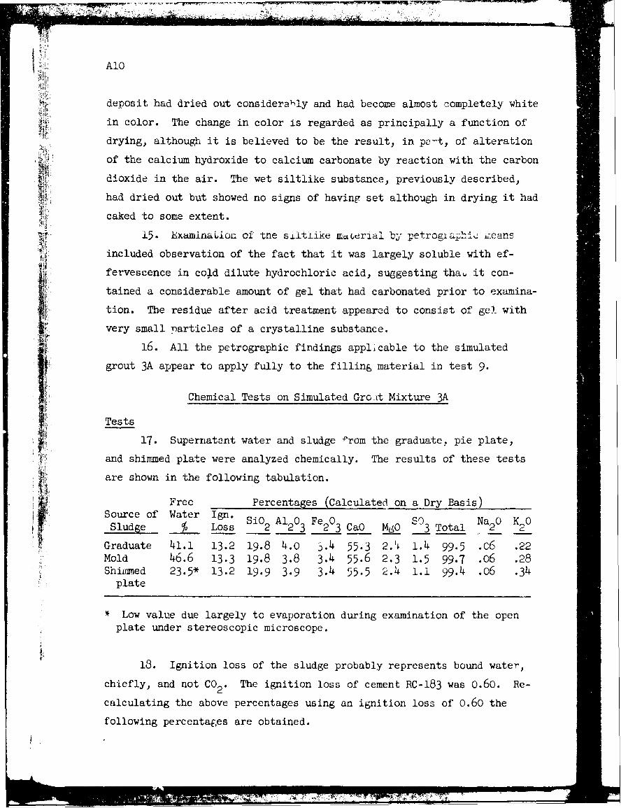
AIO
r deposit had dried out considerally and had become almost completely white
in color. The change in color is regarded as principally a function of
drying, although it is believed to be the result, in peat, of alteration
.L of the calcium hydroxide to calcium carbonate by reaction with the carbon
dioxide in the air. The wet siltlike substsnice, previously described,
had dried out but showed no signs of having set although in drying it had
caked to some extent.
i5. Examination of the siitlike m~uerial by petrographi.c*'means
included observation of the fact that it was largely soluble with ef-
fervescence in cold dilute hydrochloric acid, suggesting thau it con-
tained a considerable amount of gel that had carbonated prior to examina-
tion. The residue after acid treatment appeared to consist of gel with
very small particles of a crystalline substance.
16. All the petrographic findings applicable to the simulated
grout 3A appear to apply fully to the filling material in test 9.
Chemical Tests on Simulated Gro~tt Mixture 3A
Tests
17. Supernatant water and sludge Prom the graduate, pie plate,
and shimmed plate were analyzed chemically. The results of these tests
are shown in the following tabulation.
Free Percentages (Calculated on a Dry Basis)Source of Water Ign. Si0 Al20 Fe20 C 3 Na20 K20Sludge % Loss 2 23 23Ca0 MgO 3Total 2 2
Graduate 41.1 13.2 19.8 4.0 3.4 55.3 2.4 1.4 99.5 .x6 .22Mold 46.6 13.3 19.8 3.8 3.4 55.6 2.3 1.5 99.7 .o6 .28Shianxed 23.5* 13.2 19.9 3.9 3.4 55.5 2.4 1.1 99.4 .c6 .34plate
Low value due largely to evaporation during examination of the open
plate under stereoscopic microscope.
18. Ignition loss of the sludge probably represents bound water,
chiefly, and not CO2. The ignition loss of cement RC-183 was 0.60. Re-
calculating the above percentages using an ignition loss of 0.60 the
following percentages are obtained.
L~
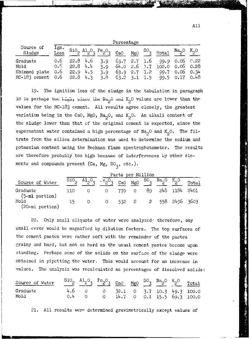
All
PercentageSourcdge of Logn Si0 2 A1203 Fe203 CaO MgO 3 Total 2 2
Graduate 0.6 22.8 4.6 3.9 63.7 2.7 1.6 99.9 0.06 0.22Mold 0.6 22.8 4.4 3.9 64.0 2.6 1.7 100.0 0.06 0.28Shimmed plate 0.6 22.9 4.5 3.9 63.9 2.7 1.2 99.7 o.o6 0.34RC-183 cement 0.6 22.8 4.3 3.8 63.2 3.1 1.5 99.5 0.17 0.48
19. The ignition loss of the sludge in the tabulation in paragraph
lb is perhaps too Lit, 'iiu lid 20 CJd K 20 values are lower than the
values for the RC-183 cement. All results agree closely, the greatest
variation being in the CaO, MgO, Na20, and K20. An alkali content of
the sludge lower than that of the original cement is expected, since the
supernatant water contained a high percentage of Na20 and K20. The fil-
trate from the silica determination was used to determine the scdium and
potassium content using the Beckman flame spectrophotometer. The results
are therefore probably too high because of interferences by other ele-
ments and compounds present (Ca, Mg, S03, etc.).
Parts per Million
Source of Water Si02 A1203 -e203 CaO MgO so3 Na20 K20 Total
Graduate 110 0 0 770 0 89 248 1184 2401(5-ml portion)
Mold 15 0 0 532 2 2 558 2496 3603(20-ml portion)
20. Only small aliquots of water were analyzed" therefore, any
small error would be magnified by dilution factors. The top surfaces of
the cement pastes were rather soft with the remainder of the pastes
grainy and hard, but not as hard as the usual cement pastes become upon
standing. Perhaps some of the solids on the surface of the sludge were
obtained in pipetting the water. This would account for an increase in
values. The analysis was recalculated as percentages of dissolved solids:
Source of Water Si02 A1203 Fe203 CaO M90 so3 Na20 K20 Total
Graduate 4.6 0 0 32.1 0 3.7 10.3 49.3 100.0Mold 0.4 0 0 14.7 0 0.1 15.5 69.3 1O0.0
21. All results were determined gravimetrically except values of
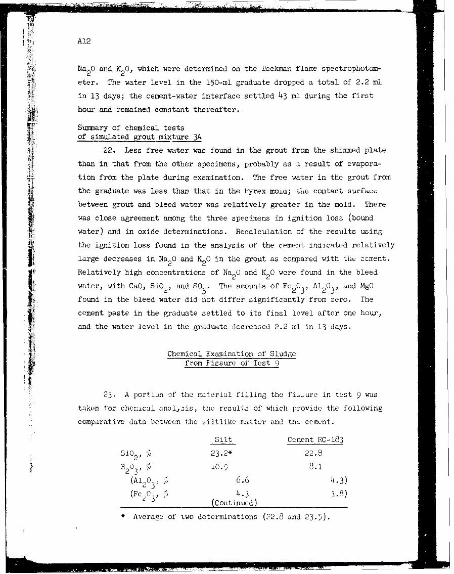
A12
Na2 0 and K 0, which were determined on the Beckman flame spectrophotom-2 2eter. The water level in the 150-ml graduate dropped a total of 2.2 ml
in 13 days; the cement-water interface settled 43 ml during the first
hour and remained constant thereafter.
Summary of chemical tests
of simulated grout mixture 3A
22. Less free water was found in the grout from the shimmed plate
Z. than in that from the other specimens, probably as a result of evapora-
tion from the plate during examination. The free water in the grout from
the graduate was less than that in the Pyrex mold; the contact surfaue
between grout and bleed water was relatively greater in the mold. There
was close agreement among the three specimens in ignition loss (bound
water) and in oxide determinations. Recalculation of the results using
the ignition loss found in the analysis of the cement indicated relatively
Ii large decreases in Na 0 and K 0 in the grout as compared with tht cement.
Relatively high concentrations of Na 0 and K 0 were found in the bleed2 2It water, with CaO, SiO, and SO3 . The amounts of Fe2 03 , A12 03, and MgO
found in the bleed water did not differ significantly from zero. The
cement paste in the graduate settled to its final level after one hour,
and the water level in the graduate decreased 2.2 ml in 13 days.
Chemical Examination of Sludgefrom Fissure of Test 9
23. A portion Df the material filling the fi ure in test 9 was
taken for chemical anal~.is, the result3 of which provide the following
comparative data between the siltlike matter and the cement.
Silt Cement EC-183
Si02, 0 23.2* 22.8
R0 L O.) 8.12 3-(Al 3 2 ,0 , 6 1. 3 ),
(FeO 3, 4.3 3.8)(Continued)
* Average of two determinations (32.8 and 23.5).
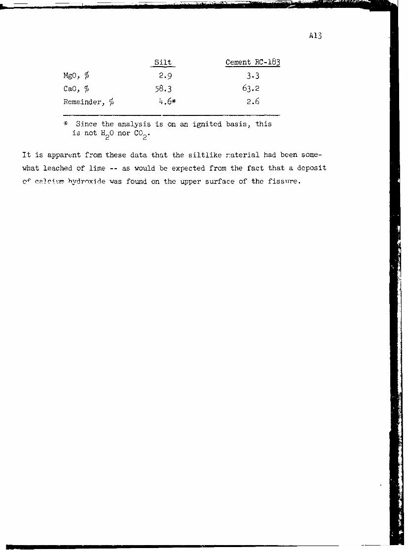
A13
Silt Cement RC-183
MgO, % 2.9 3.3
CaO, % 58.3 63.2
Remainder, % 4.6* 2.6
* Since the analysis is on an ignited basis, thisis not H 20 nor CO2 .
It is apparent from these data that the siltlike naterial had been some-
what leached of lime -- as would be expected from the fact that a deposit
o- Pcic hydroxide was found on the upper surface of the fissure.
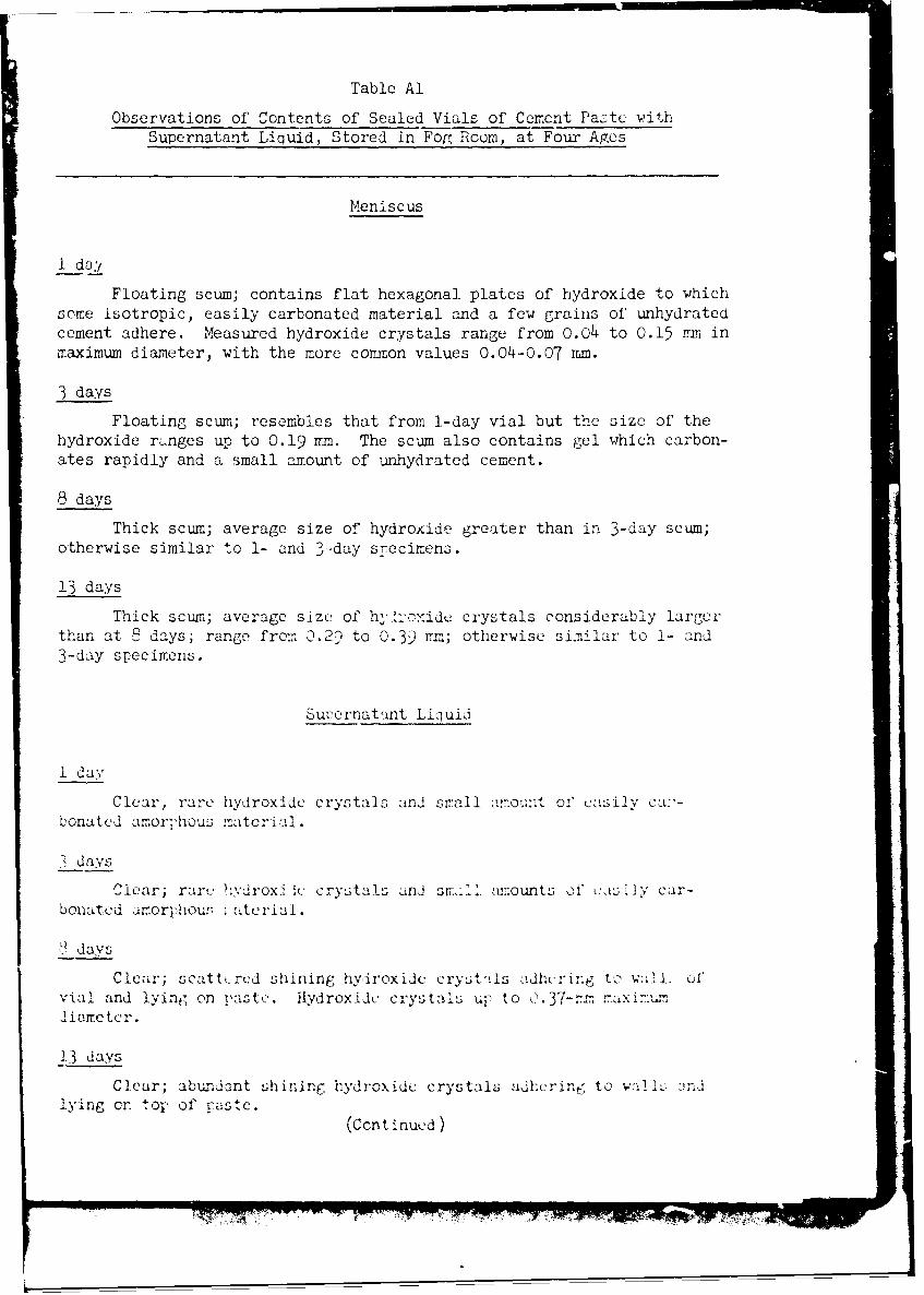
Table Al
Observations of Contents of Sealed Vials of Cement Paste withSupernatant Liquid, Stored in FoR Room, at Four Ages
Meniscus
1 do,/
Floating scum; contains flat hexagonal plates of hydroxide to whichsome isotropic, easily carbonated material and a few grains of unhydratedcement adhere. Measured hydroxide crystals range from 0.04 to 0.15 7m inmaximum diameter, with the more cornnon values 0.04-0.07 mm.
3 days
Floating scum; resembles that from 1-day vial but the size of thehydroxide rnges up to 0.19 nm. The scum also contains gel which carbon-ates rapidly and a small amount of unhydrated cement.
8 days
Thick scum; average size of hydroxide greater than in 3-day scum;otherwise similar to 1- and 3day specimens.
13 days
Thick scum; average size of hyr-oxide crystals considerably largerthan at 8 days; range from 0.29 to 0.39 1-n; otherwise similar to 1- and3-day specimens.
Su7pernatnt Liquid
1 day
Clear, rare hydroxide crystals and small arrount of easily ca:'-bonatcd amorjhou2 materiAl.
days
Clear; rar i hvdroxi ic crystals and smi anounts of cuis (y car-bonated i.orphour . aterial.
9 days
Clear; scattercd shining hydroxide cryst-i's idlicring to w-1L, Ofvial and lying on Haste. ydroxidc crystalis up to 0.37-,m maxi.:u,3iameter.
13 days
Clear; abundant shining hydroxide crystals adhcrin to wa1 i, :-,lying cn top of raste.
(Cent inued)
~~~~~-717 .'&* **". Q M* ** *

fJ
Table Al (Continued)
Paste
i '; . day4 X Dissecting needle pressed by finger penetrates about 3/4 in.
Paste looks like silt-stone; is coherent but easily broken in the hand;many deformed hydroxide plates growing parallel to the glass on the vialwalls and the outside of the plug. Under petrographic microscope cementgrains with unhydrated cores are most abundant constituent; some adhereto each other; some have gel rims. Hydroxide crystals are commonlysingle, but a few groups were found. Single crystals range in maximumdimension from 0.06 to O.±v ra; 0.13 rm most common value.
3 days
Dissecting needle pressed by finger penetrates about 3/4 in. Sim-ilar to 1-day paste under stereoscopic microscope and under petrographicmicroscope; gel rins are broader tban in 1-day hydrate, and groups ofintergrown hydroxide crysta-s ai-, more com.on. Size ranges from indi-vidual crystals 0.03 irm to groups 0.25 mm in maximum diameter.
8 days
Paste similar to 3-day paste under stereoscopic microscope. Singlehydroxide crystals up to 0.42 mm across; their thickness is about 1/10of their maximum diameter. The hydroxide groups are more complex thanthose in the 3-day paste; gel is more abundant but there is sti-l a greatnumber of recognizable cement grains.
13 days
Dissecting needle only penetrates about 3/8-1/2 in. Single hydrox-ide crystals up to 0.51 mm in maximum diameter; abundant gel and recog-
4 nizable cement grains. Hydroxide groups larger and more complex than in8-day paste.
7g
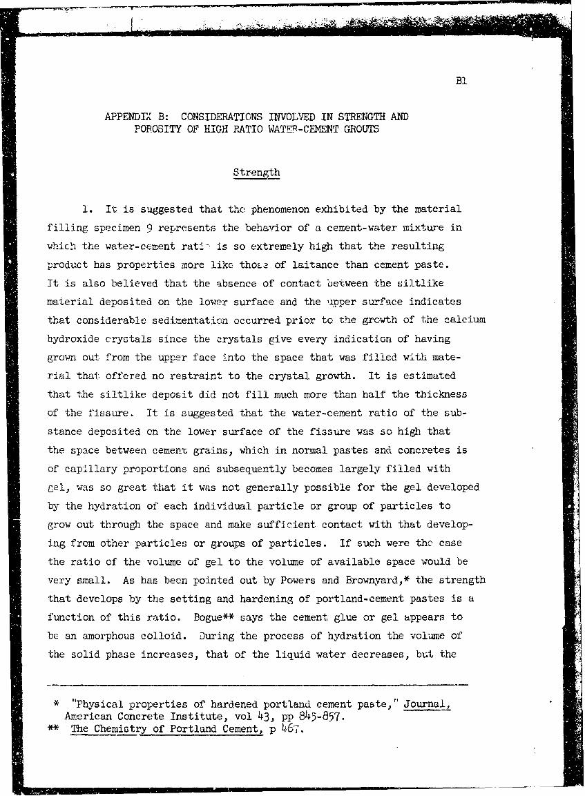
B!APPENDIX B: CONSIDERATIONS INVOLVED IN STRENGTH AND
POROSITY OF HIGH PATIO WATiR-CENET GROUTS
Strength
1. IT is suggested that the phenomenon exhibited by the material
filling specimen 9 represents the behavior of a cement-water mixture in
which the water-cement rati' is so extremely high that the resulting
product has properties more like thoa of laitance than cement paste.
It is also believed that the absence of contact between the siltlike
material deposited on the lower surface and the uiper surface indicates
that considerable sedimentation occurred prior to the growth of the calcium
hydroxide crystals since the crystals give every indication of having
grown out from the upper face into the space that was filled with mate-
rial that offered no restraint to the crystal growth. It is estimated
that the siltlike deposit did not fill much more than half the thickness
of the fissure. It is suggested that the water-cement ratio of the sub-
stance deposited on the lower surface of the fissure was so high that
the space between cement grains, which in normal pastes and concretes is
of capillary proportions and subsequently becomes largely filled with
gel, was so great that it was not generally possible for the gel developed
by the hydration of each individual particle or group of particles to
grow out through the space and make sufficient contact with that develop-
ing from other particles or groups of particles. If such were the case
the ratio of the volume of gel to the volume of available space would be
very small. As has been pointed out by Powers and Brownyard,* the strength
that develops by the setting and hardening of portland-cement pastes is a
function of this ratio. Bogue** says the cement glue or gel appears to
be an amorphous colloid. During the process of hydration the volume of
the solid phase increases, that of the liquid water decreases, but the
* "Physical properties of hardened portland cement paste," Journal,
American Concrete Institute, vol 43, pp 845-857.** The Chemistry of Portland Cement, p 46".

B2
volume of the system, cement pius water, decreases. Selective settling
of the larger or heavier grains takes place in the early stages of the
reaction, before a stiffening of the paste, leaving a layer of fine mate-
rial with a high water content known as laitance.
2. The following is based on the work of Powers and Browne.rd*:
a. The increase in the bulk volume of a paste upon hydrationis:
o.86o (wn + W
where
w = nonevaporable waternV = weight of water proportional to the gel mate-
rial in the paste (4Vm = weight of water re-quired to fill all the voids in the gel)
0.860 = mean specific volume of evaporable and non-evaporable water.
b. Hence the ratio of the increase in solid phase to theoriginal space available is:
0.860 (w + 4n )
w
where
w = original water content of paste
~vzzz m- = aconstant.
V
c.. Therefore the ratio of increase in solid phase to originali i water content (XI ) is:
' 0.86 m (l + 4k)
00
d. The compressive srength (fc is related to Xas oog
weOp. cit., p Bis
1wV
x o.6
.. . . . . -"p i l
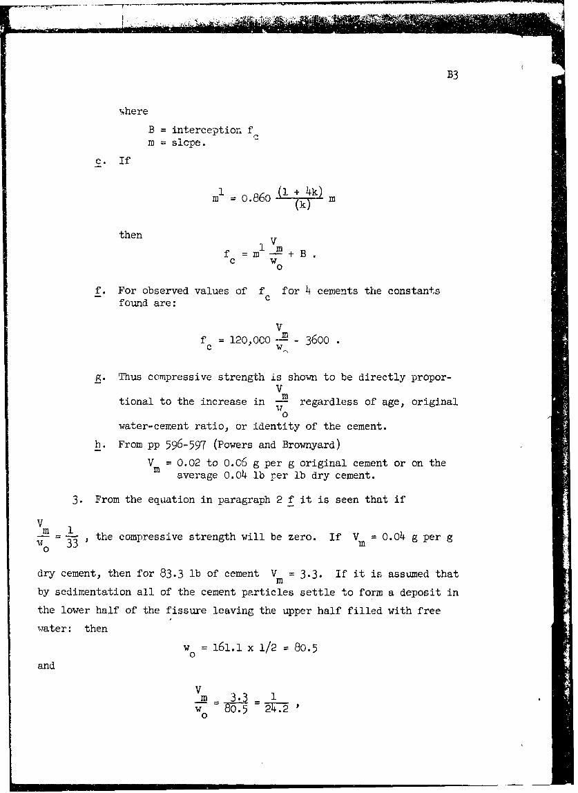
B3
,here
B = interception fm = slope.
e. If
1l=o.6 (1 + 4k)( 0k0 m
then
f =m + B.C W
0
f. For observed values of f for 4 cements the constantsfound are:
Vf = 120,000 -E - 3600 .C W
g. Thus compressive strength is shown to be directly propor-V
tional to the increase in -w regardless of age, original0
water-cement ratio, or identity of the cement.
b. From pp 596-597 (Powers and Brownyard)
V = 0.02 to 0.C6 g per g original cement or on theaverage 0.04 lb per lb dry cement.
3. From the equation in paragraph 2 f it is seen that if
Vm : - the compressive strength will be zero. If V = 0.04 g per g
140 33' i0
dry cement, then for 83.3 lb of cement V = 3.3. If it is assumed that
by sedimentation all of the cement particles settle to form a deposit in
the lower half of the fissure leaving the upper half filled with free
water: then
w = 161.1 x 1/2 = 80.50
and
V m 3wo 8 0.5 27.-2
v0|
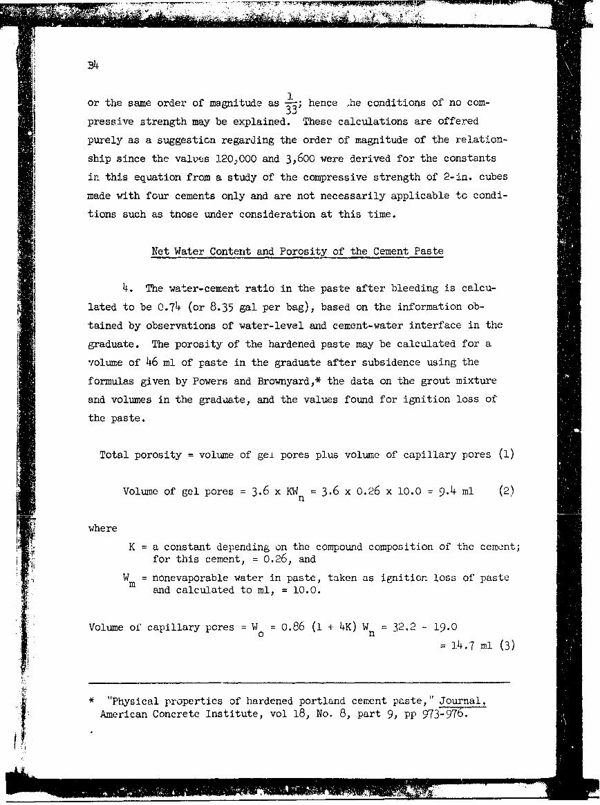
34k11
or the same order of magnitude as -; hence he conditions of no com-
or te sme oderof mgniude 33pressive strength may be explained. These calculations are offered
purely as a suggestion regarding the order of magnitude of the relation-
ship since the valves 120,000 and 3,600 were derived for the constants
in this equation from a study of the compressive strength of 2-in. cubes
made with four cements only and are not necessarily applicable to condi-
tions such as tnose under consideration at this time.
Net Water Content and Porosity of the Cement Paste
4. The water-cement ratio in the paste after bleeding is calcu-
lated to be 0.74 (or 8.35 gal per bag), based on the information ob-
tained by observations of water-level and cement-water interface in the
graduate. The porosity of the hardened paste may be calculated for a
volume of 46 ml of paste in the graduate after subsidence using the
formulas given by Powers and Brownyard,* the data on the grout mixture
and volumes in the graduate, and the values found for ignition loss of
the paste.
Total porosity = volume of gei pores plus volume of capillary pores (1)
Volume of gel pores = 3.6 x KW = 3.6 x 0.26 x lO.O = 9.4 ml (2)n
where
K = a constant depending on the compound composition of the cement;
for this cement, = 0.26, and
W = nonevaporable water in paste, taken as ignition loss of pastem and calculated to ml, = 10.0.
Volume of capillary pores = W = 0.86 (l 4 4K) W 32.2 - 19.0
O n
14.7 ml (3)
* "Physical properties of hardened portland cement paste," Journal,
Ii American Concrete Institute, vol 18, No. 8, part 9, Pp 973-976.
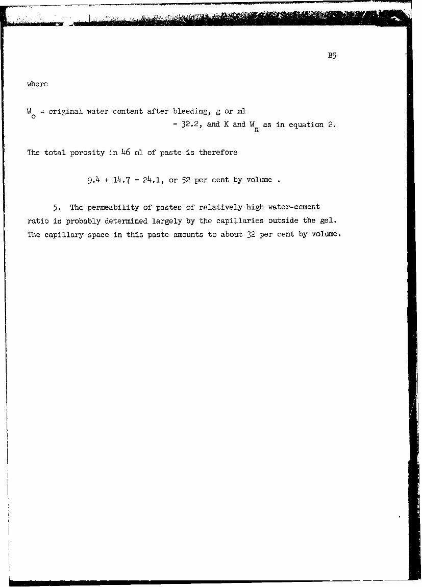
. ,. . ,.
B5
where
W = original water content after bleeding, g or ml0
= 32.2, and K and W as in equation 2.n
The total porosity in 46 ml of paste is therefore
9.4 + 14.7 = 24.1, or 52 per cent by volume
5. The permeability of pastes of relatively high water-cement
ratio is probably determined largely by the capillaries outside the gel.
The capillary space in this paste amounts to about 32 per cent by volume.