Pressure Drop Characteristics of Slit-Type Heat Exchangerpressure drop. Since cryocooler designers...
10
Pressure Drop Characteristics of Slit-Type Heat Exchanger T. Ki and S. Jeong Cryogenic Engineering Laboratory Korea Advanced Institute of Science and Technology Korea ABSTRACT A slit-type heat exchanger offers several advantages to the design of cryocoolers; it can accom- modate various configurations either in a straight or tapered shape and involves no thermal contact resistance problems, which are often encountered in a mesh-type heat exchanger. The needed heat path in the radial direction of the heat exchanger of a large-scale and high-power cryocooler is especially favorable. Our focus here is on the measurement and analysis of the pressure drop char- acteristics of a slit-type heat exchanger. First, measurement of overall pressure drop is considered under steady-flow conditions. The analyzed parameters of the heat exchanger configuration in- clude: 1) size of slit; 2) number of slits; and 3) angle of slit. Second, using the pressure boundary conditions obtained from the experiments, CFD (Computational Fluid Dynamics) was carried out to reproduce the experimental data. Using the CFD calculations, the entrance and exit losses of the pressure were carefully examined and identified. These results can divide the overall pressure drop into the entrance, exit, and tapered channel losses. Finally, we conclude that the pressure drop characteristics under steady flow conditions can be used for conditions of oscillating flow. The presented results should help one design an optimum regenerative cryocooler with slit-type heat exchangers. INTRODUCTION A heat exchanger is one of the most important components of a cryocooler. The aftercooler and warm-end heat exchanger in a Stirling-type cryocooler should be able to dump sufficient heat and entropy to the outside for the cryocooler to reach a desirable low temperature. A cold-end heat exchanger needs to be carefully designed for satisfying the required performance and temperature stability between the gas and the heat exchanger at the cryogenic temperature. It is important to know the flow and the heat transfer characteristics of the heat exchangers for optimal design of cryocoolers. A slit-type heat exchanger has several advantages. 1-5 If a slit-type heat exchanger is employed as a straight or tapered shape, cryocoolers having different flow cross-sections around the aftercooler, cold-end, and warm-end heat exchanger can have smooth flow transitions. The slit-type heat ex- changer also has no thermal contact resistance problems that are often encountered with a mesh- type construction, and the appropriate heat path in the radial direction in a large scale and high- power PTR is especially favorable. Although the optimal design of a pulse tube refrigerator with slit-type heat exchangers necessitates knowledge of their flow and heat transfer characteristics, 201
Transcript of Pressure Drop Characteristics of Slit-Type Heat Exchangerpressure drop. Since cryocooler designers...

Pressure Drop Characteristics of Slit-Type
Heat Exchanger
T. Ki and S. Jeong
Cryogenic Engineering Laboratory
Korea Advanced Institute of Science and Technology
Korea
ABSTRACT
A slit-type heat exchanger offers several advantages to the design of cryocoolers; it can accom-
modate various configurations either in a straight or tapered shape and involves no thermal contact
resistance problems, which are often encountered in a mesh-type heat exchanger. The needed heat
path in the radial direction of the heat exchanger of a large-scale and high-power cryocooler is
especially favorable. Our focus here is on the measurement and analysis of the pressure drop char-
acteristics of a slit-type heat exchanger. First, measurement of overall pressure drop is considered
under steady-flow conditions. The analyzed parameters of the heat exchanger configuration in-
clude: 1) size of slit; 2) number of slits; and 3) angle of slit. Second, using the pressure boundary
conditions obtained from the experiments, CFD (Computational Fluid Dynamics) was carried out
to reproduce the experimental data. Using the CFD calculations, the entrance and exit losses of the
pressure were carefully examined and identified. These results can divide the overall pressure drop
into the entrance, exit, and tapered channel losses. Finally, we conclude that the pressure drop
characteristics under steady flow conditions can be used for conditions of oscillating flow. The
presented results should help one design an optimum regenerative cryocooler with slit-type heat
exchangers.
INTRODUCTION
A heat exchanger is one of the most important components of a cryocooler. The aftercooler and
warm-end heat exchanger in a Stirling-type cryocooler should be able to dump sufficient heat and
entropy to the outside for the cryocooler to reach a desirable low temperature. A cold-end heat
exchanger needs to be carefully designed for satisfying the required performance and temperature
stability between the gas and the heat exchanger at the cryogenic temperature. It is important to
know the flow and the heat transfer characteristics of the heat exchangers for optimal design of
cryocoolers.
A slit-type heat exchanger has several advantages.1-5
If a slit-type heat exchanger is employed
as a straight or tapered shape, cryocoolers having different flow cross-sections around the aftercooler,
cold-end, and warm-end heat exchanger can have smooth flow transitions. The slit-type heat ex-
changer also has no thermal contact resistance problems that are often encountered with a mesh-
type construction, and the appropriate heat path in the radial direction in a large scale and high-
power PTR is especially favorable. Although the optimal design of a pulse tube refrigerator with
slit-type heat exchangers necessitates knowledge of their flow and heat transfer characteristics,
201

there is little research that has been conducted for such a purpose. Only a parallel rectangular chan-
nel approximation has been used to characterize a slit-type heat exchanger in a design process. The
characteristics of slit-type heat exchangers are quite different from those of parallel rectangular
channels in that a slit-type heat exchanger has both radially dispersed and axially tapered channel
effects. Especially in the region around the entrance, tapered channel, and exit, the characteristics
of pressure drop must be significantly different from that of a parallel rectangular channel.
In this paper, pressure drop characteristics of slit-type heat exchanger are investigated through
flow measurements and CFD analysis. For various configurations of slit-type heat exchangers, each
pressure drop has been measured under steady flow conditions. Measurements in both the positive
and negative flow directions have been conducted in consideration of the conditions of oscillating
flow. The measured pressure drop has been decoupled by entrance, tapered channel, and exit loss
using CFD. Finally, we show that the pressure drop characteristics of steady flow can be used for
oscillating flow by considering the acoustic impedance of slit-type heat exchangers.
PRESSURE DROP COMPONENTS
A typical installation of a heat exchanger involves flow contraction and expansion at the core
entrance and exit. This frontal flow area change complicates the characteristics of flow-stream
pressure drop. Since cryocooler designers are usually interested in the overall pressure drop of the
heat exchanger, rather than the specific local core friction pressure drop, it is useful and informative
to understand how the overall pressure drop is distributed along the heat exchanger assembly. In the
case of a regenerative cryocooler design where the system pressure is oscillating, the entrance and
exit effects are important in the whole design process. The amplitude of the entrance and exit losses
cannot be ignored in comparison with the core loss of the heat exchanger, and also asymmetric
characteristics of the entrance and exit effects can generate DC flow in a pulse tube cryocooler. It is,
therefore, necessary to examine the overall pressure drop and identify each pressure drop compo-
nent for optimal design of cryocoolers.
For steady flow, a typical pressure drop curve of a heat exchanger with rectangular channels is
depicted in Fig. 2. It is separated by the entrance, channel, and exit parts.6
If the heat exchanger has
a symmetric configuration at the entrance and exit regions, the pressure drop characteristic is the
same regardless of the flow direction. However, a slit-type heat exchanger has usually an asymmet-
ric configuration because the tapered channel height changes along the channel length to accommo-
date different flow cross-sections in adjacent components of a cryocooler.7,8
For complete under-
standing of pressure loss under oscillating flow conditions, the pressure drop in both flow direc-
tions should be known and decoupled in the entrance, exit, and tapered channel regions as shown in
Fig. 3.
The overall pressure drop of silt-type heat exchangers having different number, angle, and size
of the slit have been measured under steady flow conditions in both flow directions. By using the
pressure drop measurements as the boundary conditions, CFD analysis has also performed. The
CFD analysis enables one to decouple the entrance, tapered channel, and exit losses, respectively.
Figure 1. Slit-type heat exchanger.
202 PULSE TUBE ANALYSIS AND EXPERIMENTAL MEASUREMENTS

Figure 4. Experimental apparatus for steady flow measurements.
Figure 3. Schematic of pressure drop
components in the oscillating condition.
Figure 2. Pressure drop components in a heat
exchanger channel.
The analysis helps one understand the flow characteristic around the heat exchanger in both flow
directions. The obtained entrance and exit losses under steady flow conditions are applied to oscil-
lating pressure and flow conditions after the pressure drop of the tapered channel is checked with
respect to the phase change that is generated by the compliance effect.
EXPERIMENTAL SETUP AND SLIT-TYPE HEAT EXCHANGERS
The experimental apparatus used in this research is shown schematically in Fig. 4. Static pres-
sure sensors (Honeywell®
) and differential pressure sensors (Validyne® DP15) are used for measur-
ing the overall pressure drop between the slit-type heat exchangers. Two static pressure sensors are
for measuring entry static pressure according to the flow direction. The overall pressure drop is
measured by an outer differential pressure sensor and this result is used for the pressure boundary
conditions of the CFD simulation. The overall pressure drop measured by the inner differential
pressure sensor is used for confirming the CFD simulation results. We have employed a liquid
nitrogen tank and its evaporator to supply the desired mass flow rate in the range of 10 g/s, and we
continuously maintain the charge pressure using a regulator. The mass flow rate is measured and
controlled by a Coriolis mass flow meter (MaxFlo®
) and a needle valve (Swagelok®
). Temperature
as well as pressure are monitored during an experiment in order to calculate nitrogen gas density.
Measured data are saved by a Data Acquisition System (DAS) for archival purposes.
Six slit-type heat exchangers with different configurations as shown in Fig. 5 and tabulated in
Table 1 were used in the experiments. These are all copper blocks with tapered slit channels, and
each has a diameter change from the entrance to the exit region to match standardized tube diameter
sizes (2.25 inch, 1.25 inch, 1 inch and 0.5 inch) used for typical linear-compressor cylinder, regen-
erator, and pulse tube construction. After making a small hole in the copper block center using a
super drill, the tapered slits in the heat exchanger are fabricated by Electrical Discharge Machining
(EDM). The small center hole is later blocked by a machined brass bar.
203PRESSURE DROP OF SLIT-TYPE HEAT EXCHANGERS

Figure 5. Configurations of slit-type heat exchangers.
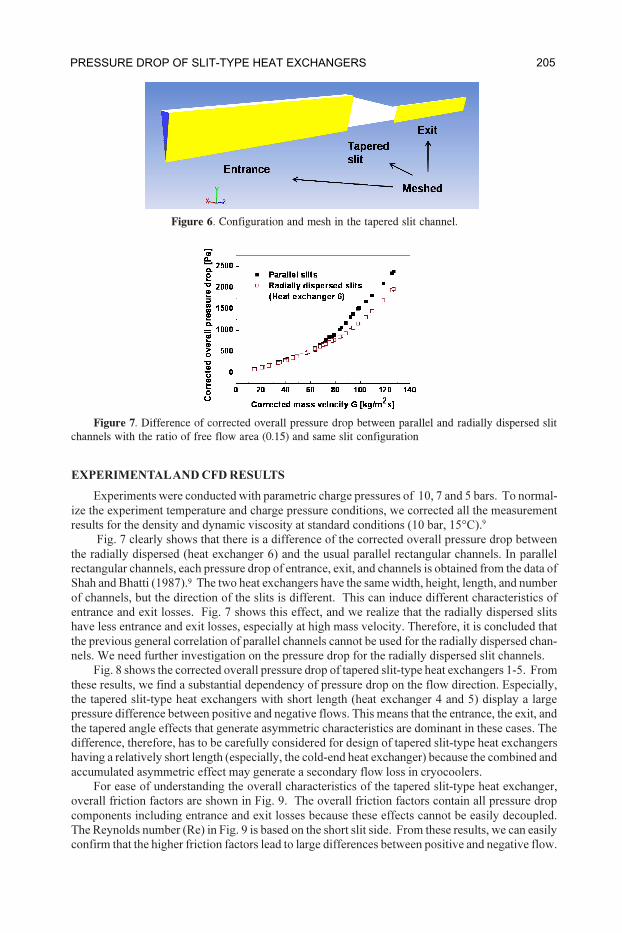
CFD
The CFD simulation program, Fluent®
, was used to separate the effects attributable to the
individual pressure drop components in the tapered slit-type heat exchangers. Symmetry was used
to allow each slit-type heat exchanger to be modeled for computation purposes by a single slit as
shown in Fig. 6. All grids were carefully created and tested with Gambit in three dimensions to
insure the generation of high quality grids in slits having a very large aspect ratio. All computa-
tional models used a pressure-based numerical solver for the steady state condition and employed a
second order upwind method control scheme with a SIMPLE pressure-velocity coupling. As a
result of the high Reynolds number observed in the tapered slit channel and in the extended inlet
and outlet regions, a realizable k-Ü turbulence model was applied. In all cases, inlet and outlet
pressure boundary conditions measured from the experiments were used, and pressure gradients
were calculated in the tapered slit-type heat exchangers. From the calculated results, each pressure
drop component was separated and characterized by its friction factor, entrance, and exit loss coef-
ficients as follows.6
(1)
where,
Dh
is the hydraulic diameter
f is the friction factor
G is the mass velocity
L is the channel length
Kc
is the contraction loss coefficient
Ke
is the expansion loss coefficient
ò is the ratio of free flow area
204 PULSE TUBE ANALYSIS AND EXPERIMENTAL MEASUREMENTS
EXPERIMENTAL AND CFD RESULTS
Experiments were conducted with parametric charge pressures of 10, 7 and 5 bars. To normal-
ize the experiment temperature and charge pressure conditions, we corrected all the measurement
results for the density and dynamic viscosity at standard conditions (10 bar, 15°C).9
Fig. 7 clearly shows that there is a difference of the corrected overall pressure drop between
the radially dispersed (heat exchanger 6) and the usual parallel rectangular channels. In parallel
rectangular channels, each pressure drop of entrance, exit, and channels is obtained from the data of
Shah and Bhatti (1987).9 The two heat exchangers have the same width, height, length, and number
of channels, but the direction of the slits is different. This can induce different characteristics of
entrance and exit losses. Fig. 7 shows this effect, and we realize that the radially dispersed slits
have less entrance and exit losses, especially at high mass velocity. Therefore, it is concluded that
the previous general correlation of parallel channels cannot be used for the radially dispersed chan-
nels. We need further investigation on the pressure drop for the radially dispersed slit channels.
Fig. 8 shows the corrected overall pressure drop of tapered slit-type heat exchangers 1-5. From
these results, we find a substantial dependency of pressure drop on the flow direction. Especially,
the tapered slit-type heat exchangers with short length (heat exchanger 4 and 5) display a large
pressure difference between positive and negative flows. This means that the entrance, the exit, and
the tapered angle effects that generate asymmetric characteristics are dominant in these cases. The
difference, therefore, has to be carefully considered for design of tapered slit-type heat exchangers
having a relatively short length (especially, the cold-end heat exchanger) because the combined and
accumulated asymmetric effect may generate a secondary flow loss in cryocoolers.
For ease of understanding the overall characteristics of the tapered slit-type heat exchanger,
overall friction factors are shown in Fig. 9. The overall friction factors contain all pressure drop
components including entrance and exit losses because these effects cannot be easily decoupled.
The Reynolds number (Re) in Fig. 9 is based on the short slit side. From these results, we can easily
confirm that the higher friction factors lead to large differences between positive and negative flow.
Figure 7. Difference of corrected overall pressure drop between parallel and radially dispersed slit
channels with the ratio of free flow area (0.15) and same slit configuration
Figure 6. Configuration and mesh in the tapered slit channel.
205PRESSURE DROP OF SLIT-TYPE HEAT EXCHANGERS

(a) Heat exchanger 1, 2 and 3 (b) Heat exchanger 4 and 5
Figure 8. Corrected overall pressure drop in tapered slit-type heat exchangers
(a) Heat exchanger 1, 2 and 3 (b) Heat exchanger 4 and 5
Figure 9. Overall friction factors in tapered slit-type heat exchangers.
This means that high friction factor or low Reynolds number conditions can induce larger asym-
metric characteristics of pressure drop. Since the experimental cases have different overall friction
factor curves, nondimensional parameters are used for generalizing the overall friction factor.
The taper angle (ï) and the ratio of the free flow area to the frontal and back area (òinlet
, òoutlet
),
which embody the width, height, and number of slits in the heat exchanger, are considered in the
definition of the overall friction factor as follows:
(2)
Fig. 10 shows the accuracy of the correlated overall friction factors. In this generalized overall
friction factor, the positive and the negative flow correlations have maximum errors of 8¶% and
15%, respectively.
Realizing the difficulty of applying the overall friction factor for diverse slit-type heat ex-
changers, we tried to decouple the genuine effect of pressure drop due to the tapered slit from the
entrance and exit losses. Fig. 11 and Fig. 12 show the CFD results for heat exchanger 4 for positive
flow conditions. The individual entrance and exit loss trends are similar to those for the parallel
206 PULSE TUBE ANALYSIS AND EXPERIMENTAL MEASUREMENTS

(a) Positive flow (b )Negative flow
Figure 10. Accuracy of correlated overall friction factors.
Figure 11. Divided entrance and exit losses. Figure 12. Pressure drop curve from CFD.
rectangular slits, but the amplitudes of the entrance and exit losses are different. Especially, the exit
losses always have a small amplitude, and the entrance losses have a large amplitude for increasing
Reynolds numbers. This means that the effect due to the tapered angle and the radially dispersed
slits is important. Since the tapered slit channels with large aspect ratios require a very large grid
number for CFD, the CFD simulation with the turbulent model consumes a huge amount of time for
obtaining accurate results. The CFD simulation could not be completed for all heat exchanger
cases; a more efficient method is necessary.
APPLICATION FOR OSCILLATING FLOW CONDITIONS
It may be questioned if the steady-flow correlation obtained in the previous section is useful for
the oscillating flow conditions in a cryocooler design. This section specifically considers the effi-
cacy of the steady pressure drop correlation of the slit-type heat exchanger in the view of an acous-
tic impedance model. An acoustic impedance model for oscillating gas flow in rectangular chan-
nels is commonly used for the design and analysis of harmonic systems. Generally, the acoustic
impedance of a slit is the ratio of complex amplitudes of pressure drop to volumetric flow rate and
can be expressed with resistive and reactive parts.
(3)
The acoustic impedance can be further notated by electrical elements as follows:
(4)
where R, L, and C are the acoustic resistance, inertance, and compliance of the equivalent hydraulic
system. According to previous research, these impedances are analyzed as follows, and in the case
of a rectangular channel the impedance becomes10
207PRESSURE DROP OF SLIT-TYPE HEAT EXCHANGERS

(5)
where,
a is the long dimension of the channel cross section
d is the narrow dimension of rectangular channel cross section
L is the geometric rectangular channel length
Y is î times the ratio of d to the viscous wavelength
ð is density of the gas
õ is radian frequency
In small rectangular channels where the high-aspect ratio approximation is applicable, the im-
pedance can be written as follws11
(6)
where,
b is the channel half-height
Ù is the channel aspect ratio
ã is the nondimensional frequency parameter
ì is the dynamic viscosity
The impedance of slit channels with a small void volume does not have a significant compli-
ance effect because the gas moves almost simultaneously at the inlet and exit. Therefore, the change
in pressure phase angle across a slit-type heat exchanger is not significant, as illustrated in Fig. 13.
Only the resistance part is meaningful in the pressure drop characteristic, even for most oscillating
flow conditions in regenerative cryocoolers. As shown in Fig. 3, a tapered channel can be divided
into three parts: entrance, exit, and channel regions. If the overall pressure losses obtained from the
steady flow condition can be generalized according to flow, the pressure drop of the tapered slit-
type heat exchanger can be derived for oscillating flow conditions, regardless of the gas stroke.
First, each time-averaged pressure drop generated from the entrance and the exit regions over a
cycle is obtained from Eq. (7).7
(7)
Second, at each small incremental time segment of the cycle, the velocity profile of particle
segments in the tapered channel region can be considered to be constant. If we know the friction
factor, which is obtained from the steady flow condition at this temporal velocity or Reynolds
number, the pressure loss in the tapered channel can be calculated during this time segment. There-
fore, the total pressure drop of the gas during a total stoke can be obtained by combining the channel
loss integrated over the cycle with losses for the entrance and exit regions.
SUMMARY
The pressure drop characteristics of a slit-type heat exchanger with radially dispersed and ta-
pered silts have been studied for both steady and oscillating flow conditions. First, for steady flow
conditions, the overall pressure drop of six tapered slit-type heat exchangers with different slit
configurations was measured for both flow directions, and the overall friction factors were ob-
tained. From these results, asymmetric pressure drop characteristics and different overall friction
factors were derived for each configuration of the slits and flow direction. The generalized new
overall friction factor is presented with maximum errors of 8 % and 15 % according to the flow
208 PULSE TUBE ANALYSIS AND EXPERIMENTAL MEASUREMENTS

direction. Second, CFD simulation, which allowed dividing the overall pressure drop into en-
trance, exit, and channel losses, was conducted to obtain a more accurate correlation. Finally, the
acoustic impedance method was appealed to to confirm the applicability of using the steady-flow
experimental data for the oscillating-flow conditions that commonly occur in regenerative cryo-
coolers. The pressure drop characteristics of the slit-type heat exchanger investigated in this paper
should be useful for the optimum design of large-capacity pulse tube refrigerators.
ACKNOWLEDGMENT
This work was supported by the Korea Science and Engineering Foundation (KOSEF) grant
funded by the Korea government (MOST) (No. R0A-2007-000-20062-0).
REFERENCES
1. Ki, T. and Jeong, S., “Optimal Design of Pulse Tube Refrigerator with Slit-type Heat Exchangers,”
Proc. of the 23th Space Cryogenics Workshop, Cryogenic Society of America, 2009, pp. 231-241.
2. Ki, T. and Jeong, S., “Stirling-type pulse tube refrigerator with slit-type heat exchangers for HTS
superconducting motor,” To be presented at the Asian Conference on Applied Superconductivity and
Cryogenics 2009, Matsue, 2009.
3. Ercolani, E., Poncet, J. M., Charles, I., Duband, L., Tanchon, J., Trollier, T., Ravex, A., “Design and
prototyping of a large capacity high frequency pulse tube,” Cryogenics, Vol. 48, No. 9-10 (2008), pp.
439-447.
4. Su, W., Ju, Y. L., Chen, M., “Development of miniature coaxial pulse tube cryocooler with novel
integral cold finger,” Proceedings of ICEC 22 (2008), pp. 549-554.
5. Mohanta, L. and Atrey, M. D., “Experimental investigation of single-stage in-line Stirling-type pulse
tube refrigerator,” Cryocoolers 15, ICC Press, Colorado (2009), pp. 185-189.
6. Kays, W. M. and London, A. L., Compact heat exchangers, McGraw-Hill, New York (1984).
7. Smith, B. L. and Swift, G. W., “Power dissipation and time-averaged pressure in oscillating flow
through a sudden area change,” J. Acoust. Soc. Am., Vol. 113, No. 5 (2003), pp. 2455-2463.
8. Petculescu, A. and Wilen, B. L., “Oscillatory flow in jet pumps: nonlinear effects and minor losses,” J.
Acoust. Soc. Am., Vol. 113, No. 3 (2003), pp. 1282-1292.
9. Shah, R. K. and Sekulic, D. P., Fundamentals of heat exchanger design, Wiley, New Jersey (2003).
10. Thurston, G. B. and Wood, J. K., “Acoustic impedance of rectangular tubes,” J. Acoust. Soc. Am., vol.
25, No. 5 (1953), pp. 858-860.
11. Christopher, J. M. and Fred, K. F., “The correct treatment of harmonic pressure-flow behavior in
microchannels,” Proceedings of the ASME IMECE, vol. MEMS-2, Orlando (2000), pp. 473-479.
209PRESSURE DROP OF SLIT-TYPE HEAT EXCHANGERS