Presented by: Amy L. Trahey, P.E. Great Lakes Engineering...
33
Presented by: Amy L. Trahey, P.E. Great Lakes Engineering Group, LLC
Transcript of Presented by: Amy L. Trahey, P.E. Great Lakes Engineering...

Presented by: Amy L. Trahey, P.E. Great Lakes Engineering Group, LLC

Background and History
Typical Design Characteristics
Future
Repair Options
Types of Distress
First introduced to Michigan in 1954
Economical Solution
Statistics
These types of structures, until recently, were proven to have been virtually maintenance free
Many of the original pre-stressed concrete box beam bridges are nearing 60 years old.
Realizing this type of design lacks the ability to easily retrofit, repair, and rehabilitate.

Typical span lengths range from 20 feet to 100 feet Consist of either single-cell or double-cell units
Partial or Full-Depth shear keys are typically filled with non-shrink grout
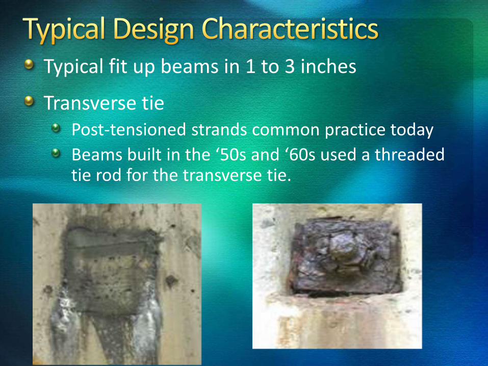
Typical fit up beams in 1 to 3 inches
Transverse tie Post-tensioned strands common practice today
Beams built in the ‘50s and ‘60s used a threaded tie rod for the transverse tie.

Wearing surface is typically Concrete or HMA
Primary structural components are single or multiple rows of pre-stressing strands

Beams built before 1980 often did not have drain holes

Pre-stressed box beams built in the ‘50s and early ‘60s did not have shear stirrups that extended across the bottom flange
These are susceptible to longitudinal cracks along the bottom flange
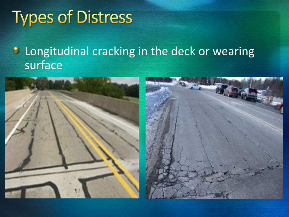
Longitudinal cracking in the deck or wearing surface

Cracking leads to leakage, which allows chloride-laden water to saturate the sides and bottoms of the beams.

Leaching between box beams

Longitudinal cracks in the bottom of box beams
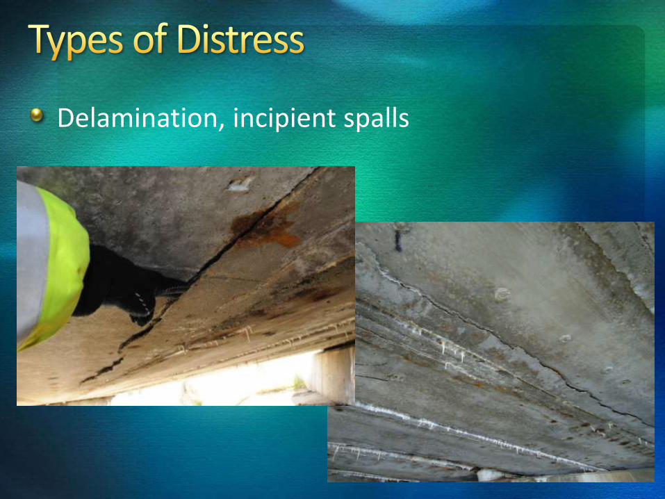
Delamination, incipient spalls
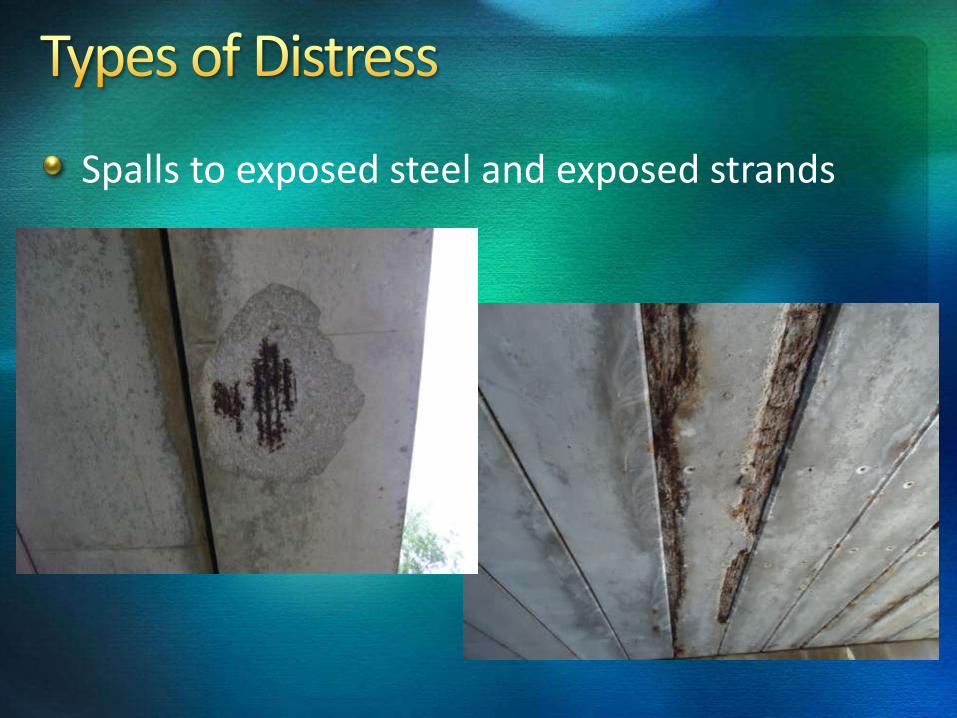
Spalls to exposed steel and exposed strands

Broken pre-stressing strands
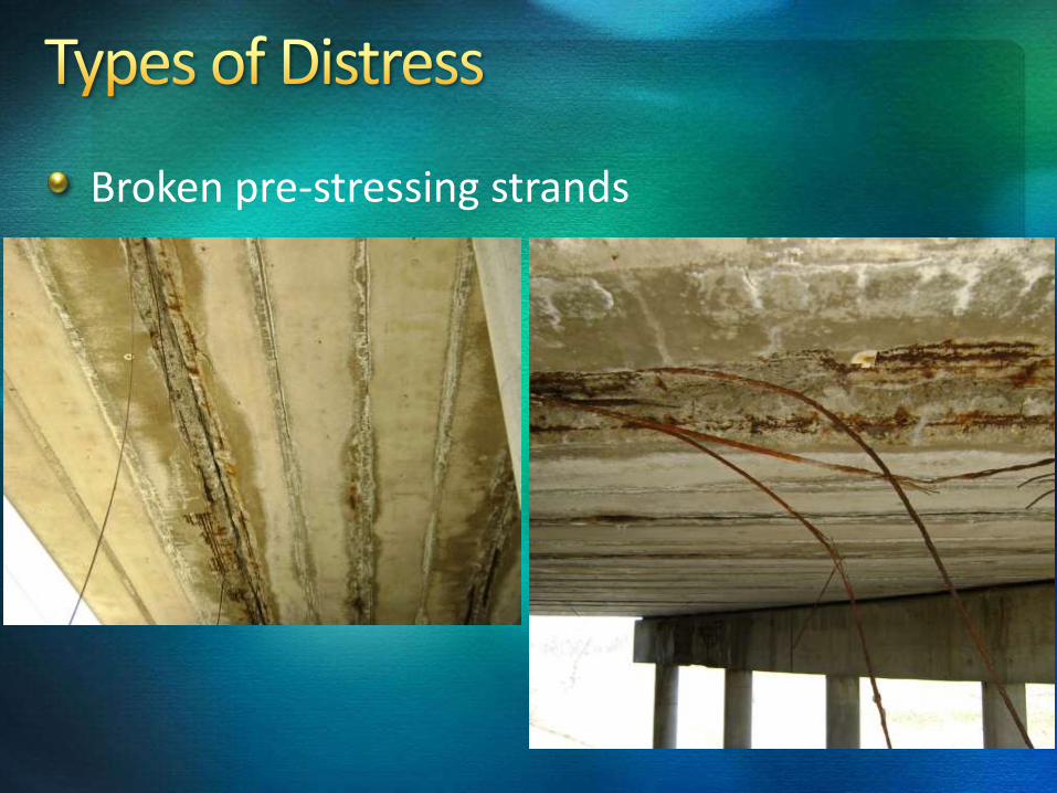
Broken pre-stressing strands

Differential movement between adjacent box beams
Results in a loss of functionality of the load transfer mechanism

Shear or flexure cracks
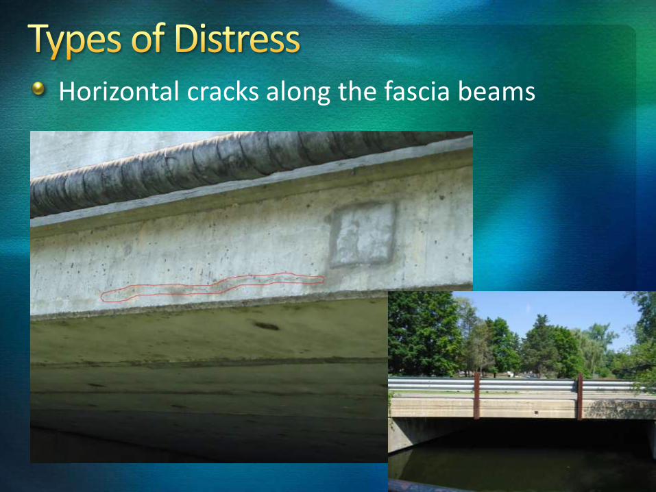
Horizontal cracks along the fascia beams

Deterioration of the top flange of the box beam
Seal the longitudinal cracks in the surface
Replace the asphalt wearing surface with a concrete deck
Replace individual beams
Splice broken pre-stressing strands
Scarify the existing asphalt surface and install a waterproofing membrane and a new asphalt overlay
Repair grouted keyway and post tensioning

Typical course of “repair” utilized today …… let it rot, load rate it, post it, shut lanes down, inspect it more frequently, and ultimately close it. This is the potential fate for adjacent concrete box beam bridges. Be prepared.

Due to the limited visual inspection techniques, this type of structure can be a “Can of Worms”
Major concern is assessing corrosion of the pre-stressing strands – that you can’t see
Concern that corrosion is affecting load carrying capacity
It is difficult for inspectors to identify independent beam action


A call for specific rating guides for adjacent pre-stressed concrete box beams to be developed to help bridge inspectors
NDT – Thermal Infrared
Radar including Synthetic Aperture Radar (SAR)
Ground Penetrating Radar (GPR)
Infrared Thermography
More Research

Inspecting adjacent concrete box beams can be challenging
Difficult to define when corrosion will affect the load-carrying capacity the bridge
Difficult to determine independent beam action or if shear keys and transverse ties are still effective in sharing the load transfer from beam to beam

The quality and efficiency of each bridge inspection is influenced by the inspector’s knowledge of how the bridge works and what controls its strength and stability
An understanding of when to conduct a load rating is critical to ensure the safety of the public