Presentation 2 (Plc)
42
PROGRAMABLE LOGIC PROGRAMABLE LOGIC CONTROLLER CONTROLLER (PLC) (PLC) “ “ A digitally operating electronic system, A digitally operating electronic system, designed for use designed for use in an industrial in an industrial environment, environment, whishes uses a programmable memory for the whishes uses a programmable memory for the internal storage of user oriented instructions internal storage of user oriented instructions for implementing specific functions such as for implementing specific functions such as logic, sequencing, timing, counting and logic, sequencing, timing, counting and arithmetic, to control, through digital or arithmetic, to control, through digital or analog inputs and outputs and various types of analog inputs and outputs and various types of machines or processes. Both the PC and its machines or processes. Both the PC and its associated peripherals are designed so that associated peripherals are designed so that they can be easily integrated into an they can be easily integrated into an industrial control system and easily used in industrial control system and easily used in all their integrated functions.” all their integrated functions.”
-
Upload
abhishek-pandey -
Category
Documents
-
view
66 -
download
16
Transcript of Presentation 2 (Plc)

PROGRAMABLE LOGIC PROGRAMABLE LOGIC CONTROLLERCONTROLLER
(PLC)(PLC) ““A digitally operating electronic system, designed A digitally operating electronic system, designed
for usefor use in an industrialin an industrial environment, whishes uses environment, whishes uses a programmable memory for the internal storage a programmable memory for the internal storage of user oriented instructions for implementing of user oriented instructions for implementing specific functions such as logic, sequencing, specific functions such as logic, sequencing, timing, counting and arithmetic, to control, timing, counting and arithmetic, to control, through digital or analog inputs and outputs and through digital or analog inputs and outputs and various types of machines or processes. Both the various types of machines or processes. Both the PC and its associated peripherals are designed so PC and its associated peripherals are designed so that they can be easily integrated into an that they can be easily integrated into an industrial control system and easily used in all industrial control system and easily used in all their integrated functions.”their integrated functions.”

HARD WIRED CONTROL SYSTEMHARD WIRED CONTROL SYSTEM
A hard wire control system is constructed only after it’s A hard wire control system is constructed only after it’s program hasprogram has been defined. Hard wire controls are difficult been defined. Hard wire controls are difficult to modify.to modify.
+24 v dc +24 v dc
Input sectionInput section
PB-1PB-1
PB-2PB-2
Processing sectionProcessing section
Lamp output sectionLamp output section
K 1 K 2

RELAY CONTROLRELAY CONTROL
The relay control can be divided in to three parts :The relay control can be divided in to three parts :
1.1. Input section – switches & sensors ( A/D ).Input section – switches & sensors ( A/D ).
2.2. Processing section –Relay coils and contacts.Processing section –Relay coils and contacts.
3.3. Output section – solenoids, lamps or motors (A/D).Output section – solenoids, lamps or motors (A/D).

PLC CONTROL SYSTEMPLC CONTROL SYSTEM
PLC replaces the function of the relay portion of the hard PLC replaces the function of the relay portion of the hard wiredwired control .control .
+ 24 v dc+ 24 v dc
PB-1 PB-1 PB-2 TO PG UNITPB-2 TO PG UNIT
Q 1Q 1
+ _ Lamp+ _ Lamp
ProgramIF I 1AND I 2THEN SET Q 1OTHER WISE RESET Q 1
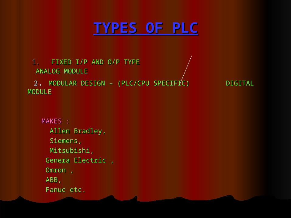
TYPES OF PLCTYPES OF PLC
1. 1. FIXED I/P AND O/P TYPE ANALOG FIXED I/P AND O/P TYPE ANALOG MODULEMODULE
22. . MODULAR DESIGN – (PLC/CPU SPECIFIC) DIGITAL MODULEMODULAR DESIGN – (PLC/CPU SPECIFIC) DIGITAL MODULE
MAKES :MAKES :
Allen Bradley,Allen Bradley,
Siemens, Siemens,
Mitsubishi,Mitsubishi,
Genera Electric ,Genera Electric ,
Omron ,Omron ,
ABB, ABB,
Fanuc etc.Fanuc etc.

COMPARISIONCOMPARISION
CHARACTERISTIC PLC RELAYCHARACTERISTIC PLC RELAY
CONSTRUCTION EASY TO PROGRAM TIME CONSUMINGCONSTRUCTION EASY TO PROGRAM TIME CONSUMING
CAPABLE OF COMPLICATED YES NOCAPABLE OF COMPLICATED YES NO
OPERATIONOPERATION
EASE OF CHANGING THE VERY SIMPLE VERY DIFFICULTEASE OF CHANGING THE VERY SIMPLE VERY DIFFICULT
COMTROL PROGRAMCOMTROL PROGRAM
PHYSICAL SIZE VERY COMPACT BULKYPHYSICAL SIZE VERY COMPACT BULKY
MAINTENANCE EXCELLENT, PLCs RARELY FAIL POOR, IF LARGE NUMBER MAINTENANCE EXCELLENT, PLCs RARELY FAIL POOR, IF LARGE NUMBER OFOF
CONTACT AND COILS HAVE CONTACT AND COILS HAVE TO BETO BE
MAINTAINEDMAINTAINED

STRUCTURE OF PLCSTRUCTURE OF PLCA PLC is essentially a micro computer with hardware, firmware and software.A PLC is essentially a micro computer with hardware, firmware and software.
Bus system : Address Bus, Data Bus, Control Bus. Bus system : Address Bus, Data Bus, Control Bus. Hardware : Actual devices-PCBs , ICs , Battery , Housing etc.Hardware : Actual devices-PCBs , ICs , Battery , Housing etc.
Firmware : software supplied and installed by manufacturer-OS Firmware : software supplied and installed by manufacturer-OS
(ROM/EPROM)(ROM/EPROM)
Software : User program written by PLC user (RAM )Software : User program written by PLC user (RAM ) Data busData bus
Address BusAddress Bus
Control Bus Control Bus
MicroprocessorCPU
ROM
Operatingsystem
RAM
Program and Data
Input Module
OutputModule
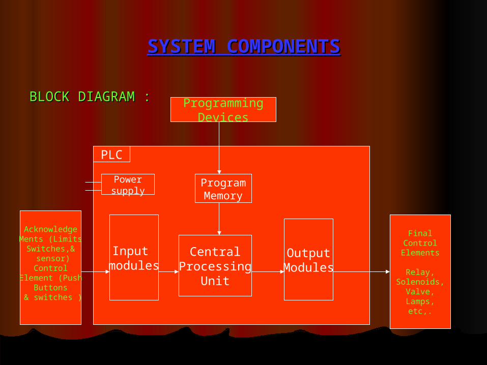
SYSTEM COMPONENTSSYSTEM COMPONENTS
BLOCK DIAGRAM :BLOCK DIAGRAM : ProgrammingDevices
AcknowledgeMents (LimitsSwitches,&
sensor)Control
Element (PushButtons
& switches )
FinalControl
Elements
Relay,Solenoids,
Valve,Lamps,
etc,.
PLC
Powersupply
Input modules
CentralProcessing
Unit
OutputModules
ProgramMemory
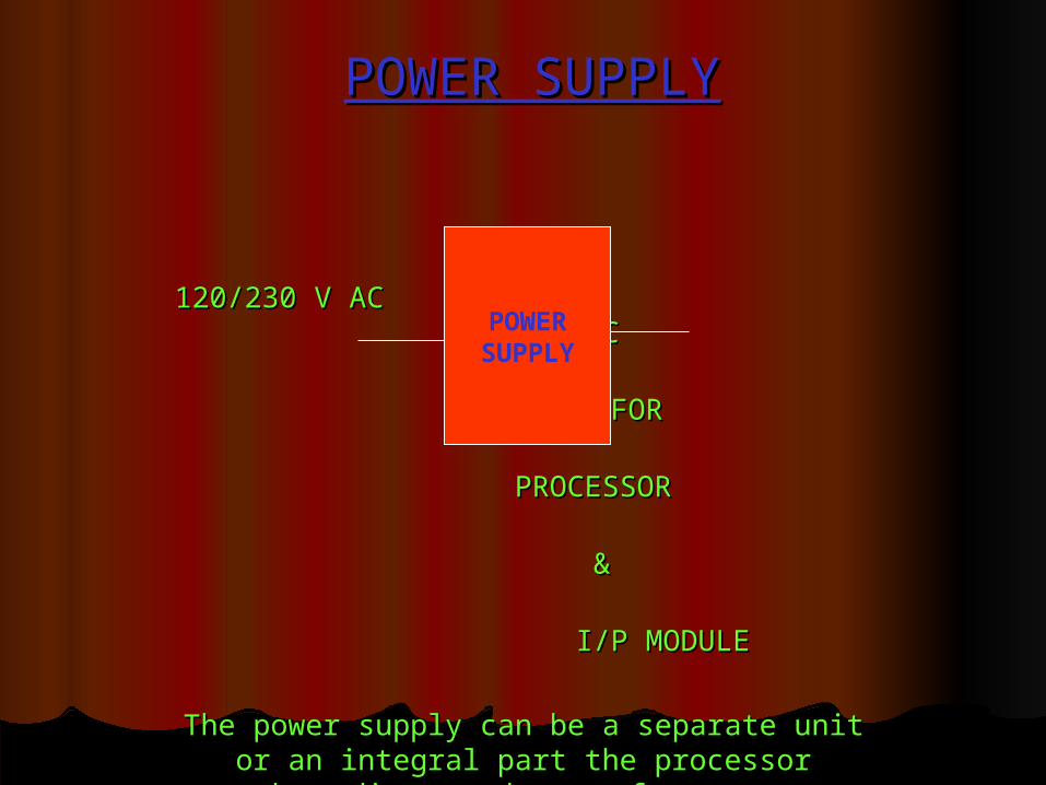
POWER SUPPLYPOWER SUPPLY
120/230 V AC120/230 V AC 24 V DC24 V DC
FORFOR
PROCESSORPROCESSOR
&&
I/P MODULEI/P MODULE
The power supply can be a separate unit or an The power supply can be a separate unit or an integralintegral part the processor depending on the part the processor depending on the
manufacturer.manufacturer.
PS307---2A/5A/10A---24 VDC---120VAC/230VACPS307---2A/5A/10A---24 VDC---120VAC/230VAC
POWERSUPPLY

INPUT & OUTPUT SECTIONINPUT & OUTPUT SECTION
(0-24 V DC)(0-24 V DC)
OR (120-240 V AC ) Low level DC OR (120-240 V AC ) Low level DC voltagevoltage
(5 V )(5 V )
Low level DC signal (120-240 V AC)Low level DC signal (120-240 V AC)
or 24 V DCor 24 V DC
Input Module
Output Module

INPUT MODULEINPUT MODULE
INPUT SIGNALINPUT SIGNAL
DI—DIGITAL INPUT (321)DI—DIGITAL INPUT (321)
AI—ANALOG INPUT (331)AI—ANALOG INPUT (331)
Error voltage detection
SIGNAL DELAY Opto -coupler
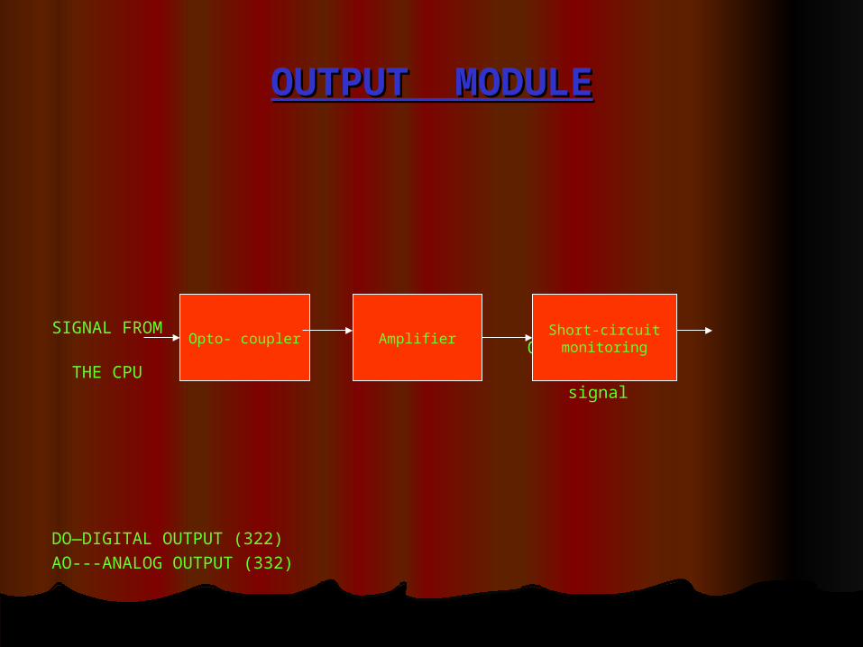
OUTPUT MODULEOUTPUT MODULE
SIGNAL FROM Output THE CPU signal
DO—DIGITAL OUTPUT (322)AO---ANALOG OUTPUT (332)
Opto- coupler AmplifierShort-circuitmonitoring

CENTRAL PROCESSING UNITCENTRAL PROCESSING UNIT
DATA BUSDATA BUS
CONTROL BUS COTROL CONTROL BUS COTROL BUSBUS
ADDRESS BUSADDRESS BUS
Arithmetic unit Control unit
ALU
Accumulator
CommandRegister
Program counter

MEMORYMEMORY
RAM ( Ram Access Memory ):RAM ( Ram Access Memory ): Read/write, Volatile ( back up by Read/write, Volatile ( back up by
battery/accumulator )battery/accumulator )
EPROM (Erasable Programmable Read Only Memory ):EPROM (Erasable Programmable Read Only Memory ): Readable Readable only. non-volatile ,ultra-violet eraser, reprogrammableonly. non-volatile ,ultra-violet eraser, reprogrammable
EEPROM (Electrically Erasable Programmable Read Only Memory EEPROM (Electrically Erasable Programmable Read Only Memory )) :Erased electrically by the proper signal at erase pin, it is :Erased electrically by the proper signal at erase pin, it is used primarily as a non-volatile back up for user program used primarily as a non-volatile back up for user program RAM, used as application memory in PLCs.RAM, used as application memory in PLCs.
Flash RAM :Flash RAM : It’s can be erased more quickly. It’s can be erased more quickly.
WORD :WORD : 8/16/32 Bits—PLC specific, 8/16/32 Bits—PLC specific,
stored binary data in form of BITS (Binary digiTS )—0/1.stored binary data in form of BITS (Binary digiTS )—0/1.
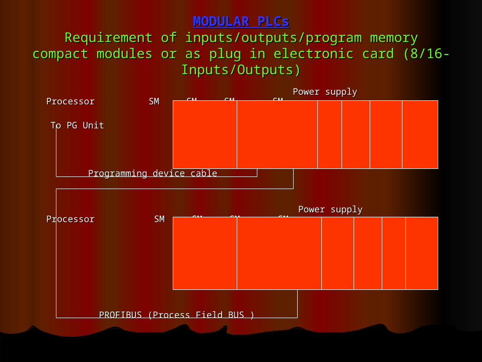
MODULAR PLCsMODULAR PLCsRequirement of inputs/outputs/program memoryRequirement of inputs/outputs/program memory
compact modules or as plug in electronic card compact modules or as plug in electronic card (8/16-Inputs/Outputs)(8/16-Inputs/Outputs)
Power supply Processor SM SM SM SMPower supply Processor SM SM SM SM
To PG UnitTo PG Unit
Programming device cableProgramming device cable
Power supply Processor SM SM SM SMPower supply Processor SM SM SM SM
PROFIBUS (Process Field BUS )PROFIBUS (Process Field BUS )
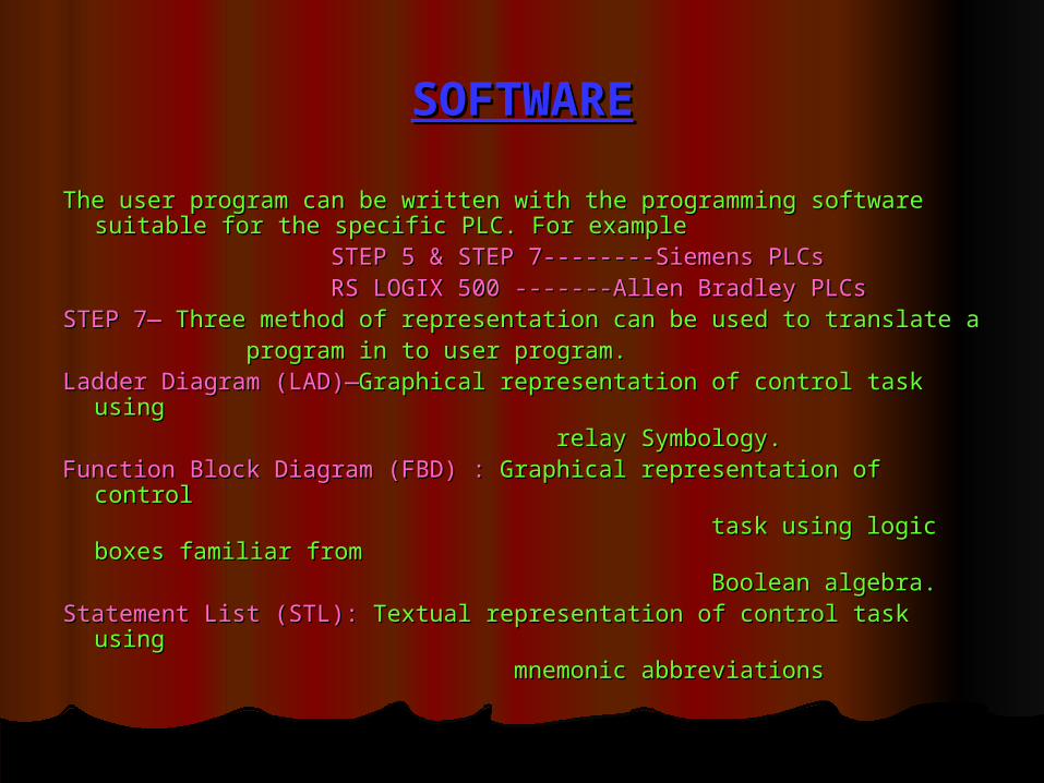
SOFTWARESOFTWARE
The user program can be written with the programming software The user program can be written with the programming software suitable for the specific PLC. For examplesuitable for the specific PLC. For example
STEP 5 & STEP 7--------Siemens PLCsSTEP 5 & STEP 7--------Siemens PLCs RS LOGIX 500 -------Allen Bradley PLCsRS LOGIX 500 -------Allen Bradley PLCsSTEP 7—STEP 7— Three method of representation can be used to translate a Three method of representation can be used to translate a program in to user program.program in to user program.Ladder Diagram (LAD)—Ladder Diagram (LAD)—Graphical representation of control task Graphical representation of control task
using using relay Symbology.relay Symbology.Function Block Diagram (FBD) :Function Block Diagram (FBD) : Graphical representation of control Graphical representation of control task using logic boxes familiar fromtask using logic boxes familiar from Boolean algebra.Boolean algebra.Statement List (STL):Statement List (STL): Textual representation of control task using Textual representation of control task using mnemonic abbreviationsmnemonic abbreviations

PLC STANDARDPLC STANDARD
Since 1992, an international standard IEC 1131 exists for Since 1992, an international standard IEC 1131 exists for programming logicprogramming logic controllers and associated peripheral devices. controllers and associated peripheral devices. The purpose of the new standard was to define and standardize The purpose of the new standard was to define and standardize the design and functionality of a PLC and the languages required the design and functionality of a PLC and the languages required for programming to the extent where users were able to operate for programming to the extent where users were able to operate using different PLC system without any difficulties. IEC 1131 using different PLC system without any difficulties. IEC 1131 standard consists of 5 parts:standard consists of 5 parts:
Part 1: General InformationPart 1: General Information Part 2: Equipment requirement & test Part 2: Equipment requirement & test Part 3: Programming LanguagesPart 3: Programming Languages Part 4: User guidelinesPart 4: User guidelines Part 5: Messaging service specificationPart 5: Messaging service specification

SIEMENS PLCsSIEMENS PLCsSIMATIC—HARDWARE+SOGTWARESIMATIC—HARDWARE+SOGTWARE
SIEMENS PROGRAMMING CONTROLLER OF S5 FAMILY.SIEMENS PROGRAMMING CONTROLLER OF S5 FAMILY.
SIMATIC S7:--SIMATIC S7:--THREE TYPES OF PROGRAMMING LOGIC THREE TYPES OF PROGRAMMING LOGIC CONTROLLERCONTROLLER
SIMATIC S7 200 :SIMATIC S7 200 : Compact micro plc for lowest performance Compact micro plc for lowest performance range.range.
SIMATIC S7 300 :SIMATIC S7 300 : Modular mini controller for intermediate Modular mini controller for intermediate
performance range.performance range.
SIMATIC S7 400 :SIMATIC S7 400 : For high performance range. For high performance range.

SIMATIC S 7 300 CONFIGURATIONSIMATIC S 7 300 CONFIGURATIONIM 365-Up to o1 meter between racksIM 365-Up to o1 meter between racks
IM 360 and IM 361-Up to 10 meter between racksIM 360 and IM 361-Up to 10 meter between racks
Allotted 08 nos.Allotted 08 nos.
Rack 0Rack 0
(IT MAY BE IN NCU )(IT MAY BE IN NCU )
IM(S)IM(S)
If not used ,then it is freeIf not used ,then it is free
Rack 1Rack 1
IM(R)IM(R)
CPU
Slot 2
IM
SLOT 3
SM SM SM SM SM SM SM SM
PS
Slot 1
IM
Slot 2
SM SM SM SM SM SM SM SM
PS
Slot 1
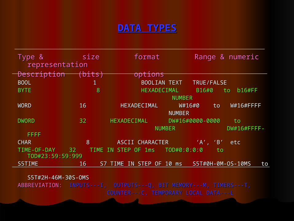
DATA TYPESDATA TYPES
Type & size format Range & numeric Type & size format Range & numeric representationrepresentation
Description (bits) optionsDescription (bits) optionsBOOL 1 BOOLIAN TEXT TRUE/FALSEBOOL 1 BOOLIAN TEXT TRUE/FALSEBYTE 8 HEXADECIMAL B16#0 to b16#FFBYTE 8 HEXADECIMAL B16#0 to b16#FF NUMBERNUMBERWORD 16 HEXADECIMAL W#16#0 to W#16#FFFFWORD 16 HEXADECIMAL W#16#0 to W#16#FFFF NUMBERNUMBERDWORD 32 HEXADECIMAL DW#16#0000-0000 toDWORD 32 HEXADECIMAL DW#16#0000-0000 to NUMBER DW#16#FFFF-FFFFNUMBER DW#16#FFFF-FFFFCHAR 8 ASCII CHARACTER ‘A’, ‘B’ etcCHAR 8 ASCII CHARACTER ‘A’, ‘B’ etcTIME-OF-DAY 32 TIME IN STEP OF 1ms TOD#0:0:0:0 to TIME-OF-DAY 32 TIME IN STEP OF 1ms TOD#0:0:0:0 to
TOD#23:59:59:999TOD#23:59:59:999S5TIME 16 S7 TIME IN STEP OF 10 ms S5T#0H-0M-OS-10MS to S5TIME 16 S7 TIME IN STEP OF 10 ms S5T#0H-0M-OS-10MS to S5T#2H-46M-30S-OMSS5T#2H-46M-30S-OMSABBREVIATION:ABBREVIATION: INPUTS---I, OUTPUTS---Q, BIT MEMORY---M, TIMERS---T,INPUTS---I, OUTPUTS---Q, BIT MEMORY---M, TIMERS---T, COUNTER---C, TEMPORARY LOCAL DATA---LCOUNTER---C, TEMPORARY LOCAL DATA---L

STEP 7 PROGRAMMING SOFTWARESTEP 7 PROGRAMMING SOFTWARE
STEP 7 IS THE PROGRAMMING SOFTWARE FOR THE SIMATIC S7STEP 7 IS THE PROGRAMMING SOFTWARE FOR THE SIMATIC S7
STEP 7 PROVIDE THE ENTIRE FUNCTIONALITY REQUIRED FOR STEP 7 PROVIDE THE ENTIRE FUNCTIONALITY REQUIRED FOR CONFIGURING,PROGRAMMING,AND ASSIGNING PARAMETERS TO CONFIGURING,PROGRAMMING,AND ASSIGNING PARAMETERS TO S7-300S7-300
STEP 7 RUNS UNDER MICROSOFT WINDOWS 95 OR HIGHERSTEP 7 RUNS UNDER MICROSOFT WINDOWS 95 OR HIGHER
STEP 7 WORKS WITH OBJECT-ORIENTED CONCEPT. THE STEP 7 STEP 7 WORKS WITH OBJECT-ORIENTED CONCEPT. THE STEP 7 OBJECTS INCLUDE STATIONS,MODULES,AND PROGRAMS.ALL OBJECTS INCLUDE STATIONS,MODULES,AND PROGRAMS.ALL OBJECT ARE REPRESENTED BY SYMBOLE ON THE GRAPHICAL USER OBJECT ARE REPRESENTED BY SYMBOLE ON THE GRAPHICAL USER INTERFACE.INTERFACE.
STEP 7 HAS A USER FRIENDLY,CONTEXT-SENSITIVE ONLINE HELP STEP 7 HAS A USER FRIENDLY,CONTEXT-SENSITIVE ONLINE HELP FUNCTION THAT GIVES VALUABLE INFORMATION AND TIPS.FUNCTION THAT GIVES VALUABLE INFORMATION AND TIPS.
THE SIMATIC MANAGER IS THE CENTRAL WINDOW WHICH IS ACTIVE THE SIMATIC MANAGER IS THE CENTRAL WINDOW WHICH IS ACTIVE WHENWHEN STEP 7 IS STARTED. STEP 7 IS STARTED.
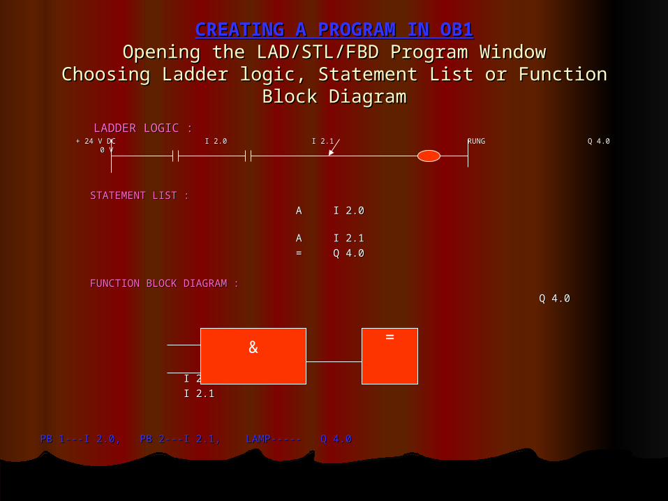
CREATING A PROGRAM IN OB1CREATING A PROGRAM IN OB1Opening the LAD/STL/FBD Program WindowOpening the LAD/STL/FBD Program Window
Choosing Ladder logic, Statement List or Function Block Choosing Ladder logic, Statement List or Function Block DiagramDiagram
LADDER LOGIC :LADDER LOGIC : + 24 V DC I 2.0 I 2.1 RUNG Q 4.0 0 V + 24 V DC I 2.0 I 2.1 RUNG Q 4.0 0 V
STATEMENT LIST :STATEMENT LIST :
A I 2.0 A I 2.0
A I 2.1A I 2.1
= Q 4.0= Q 4.0
FUNCTION BLOCK DIAGRAM :FUNCTION BLOCK DIAGRAM :
Q 4.0 Q 4.0
I 2.0I 2.0
I 2.1I 2.1
PB 1---I 2.0, PB 2---I 2.1, LAMP----- Q 4.0PB 1---I 2.0, PB 2---I 2.1, LAMP----- Q 4.0
&=

BASIC FUNCTIONBASIC FUNCTIONBinary logic operation,Binary logic operation,
Memory function,Memory function, Move function , Move function ,
Timers , Timers , Counters.Counters.
1.1. NO CONTACT NO CONTACT
2.2. NC CONTACT NC CONTACT
3.3. SINGLE COILSINGLE COIL
4.4. SERIAL AND PARALLEL CIRCUITSERIAL AND PARALLEL CIRCUIT
5.5. NEGATING THE RLO NOTNEGATING THE RLO NOT
6.6. SET AND RESET COIL , SET AND RESET COIL ,
7.7. MEMORY BOX ( SR BOX )MEMORY BOX ( SR BOX )
1.1. EDGE EVALUATION --- POSITIVE EDGE IN POWER FLOW _____(P)______EDGE EVALUATION --- POSITIVE EDGE IN POWER FLOW _____(P)______
NEGATIVE EDGE IN POWER FLOW _____(N)______NEGATIVE EDGE IN POWER FLOW _____(N)______
S R
S SR QR
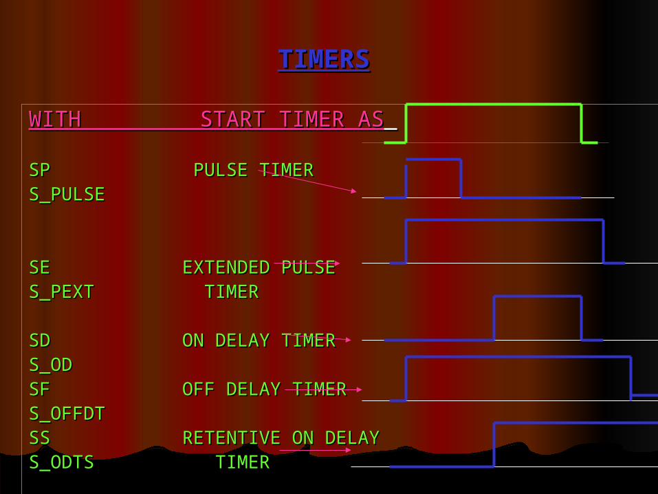
TIMERSTIMERS
WITH START TIMER ASWITH START TIMER AS SP PULSE TIMERSP PULSE TIMERS_PULSE S_PULSE
SE EXTENDED PULSESE EXTENDED PULSES_PEXT TIMERS_PEXT TIMER
SD ON DELAY TIMERSD ON DELAY TIMERS_ODS_ODSF OFF DELAY TIMER SF OFF DELAY TIMER S_OFFDTS_OFFDTSS RETENTIVE ON DELAYSS RETENTIVE ON DELAYS_ODTS TIMERS_ODTS TIMER

REPRESENTATION OF A TIMERREPRESENTATION OF A TIMER
T1T1
S-- BOOL—START INPUTS-- BOOL—START INPUT TV—S5TIME—PRESET TIME TV—S5TIME—PRESET TIME
VALU E VALU E R– BOOL---RESET INPUTR– BOOL---RESET INPUT BI—WORD---REMAINING TTIMEBI—WORD---REMAINING TTIME VALUE, INTEGERVALUE, INTEGER FORMATFORMAT BCD—WORD—REMAINING TIMEBCD—WORD—REMAINING TIME VALUE IN BCD FORMAT VALUE IN BCD FORMAT
Q--- BOOL---TIMER STATUSQ--- BOOL---TIMER STATUS
S S_ODT Q
BI
TV
BCD
R

COUNTERCOUNTER
IT’S LOCATED IN SYSTEM MEMORY,PLC SPECIFIC,IT’S LOCATED IN SYSTEM MEMORY,PLC SPECIFIC,
1. UP-DOWN COUNTER (S_CUD)1. UP-DOWN COUNTER (S_CUD)
2. UP COUNTER (S_CU)2. UP COUNTER (S_CU)
3. DOWN COUNTER (S_CD)3. DOWN COUNTER (S_CD)
4. SET COUNTER COIL4. SET COUNTER COIL
5. UP COUNTER5. UP COUNTER
6. DOWN COUNTER COIL6. DOWN COUNTER COIL
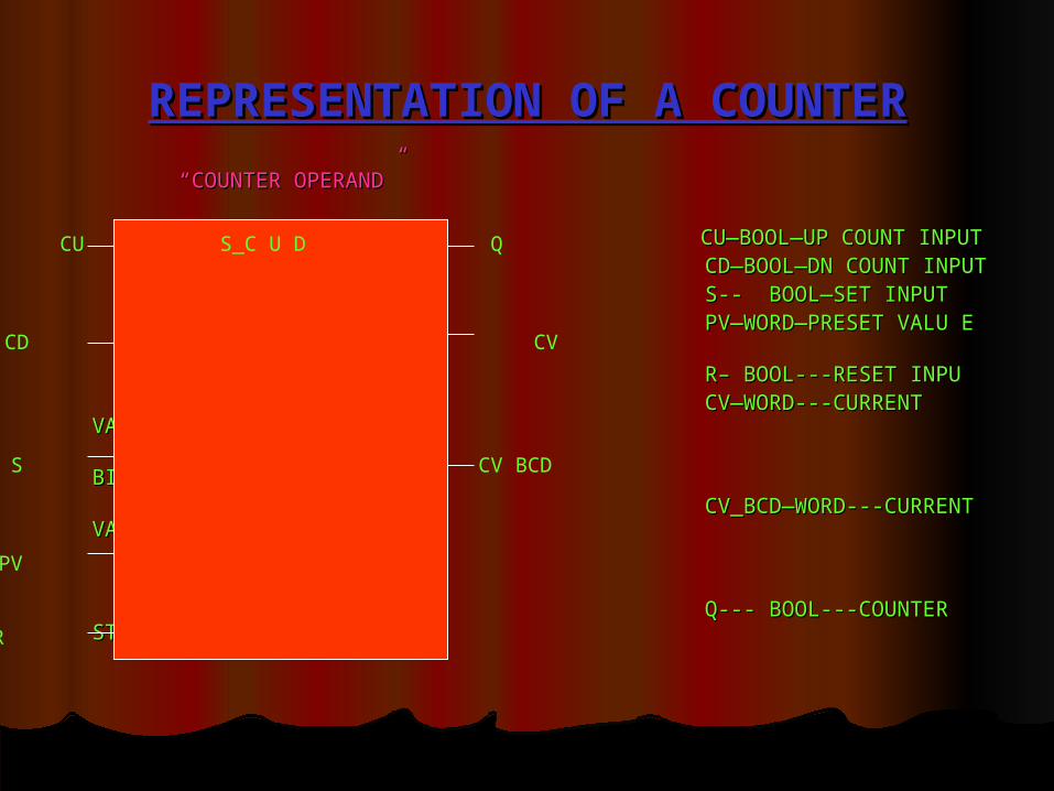
REPRESENTATION OF A COUNTERREPRESENTATION OF A COUNTER
“ “COUNTER OPERAND”COUNTER OPERAND”
CU—BOOL—UP COUNT INPUTCU—BOOL—UP COUNT INPUT CD—BOOL—DN COUNT INPUTCD—BOOL—DN COUNT INPUT S-- BOOL—SET INPUTS-- BOOL—SET INPUT PV—WORD—PRESET VALU E PV—WORD—PRESET VALU E
R– BOOL---RESET INPUR– BOOL---RESET INPU CV—WORD---CURRENT VALUE INCV—WORD---CURRENT VALUE IN BINARYBINARY CV_BCD—WORD---CURRENT VALUECV_BCD—WORD---CURRENT VALUE IN BCDIN BCD Q--- BOOL---COUNTER STATUSQ--- BOOL---COUNTER STATUS
CU S_C U D Q
CD CV
S CV BCD
PV
R
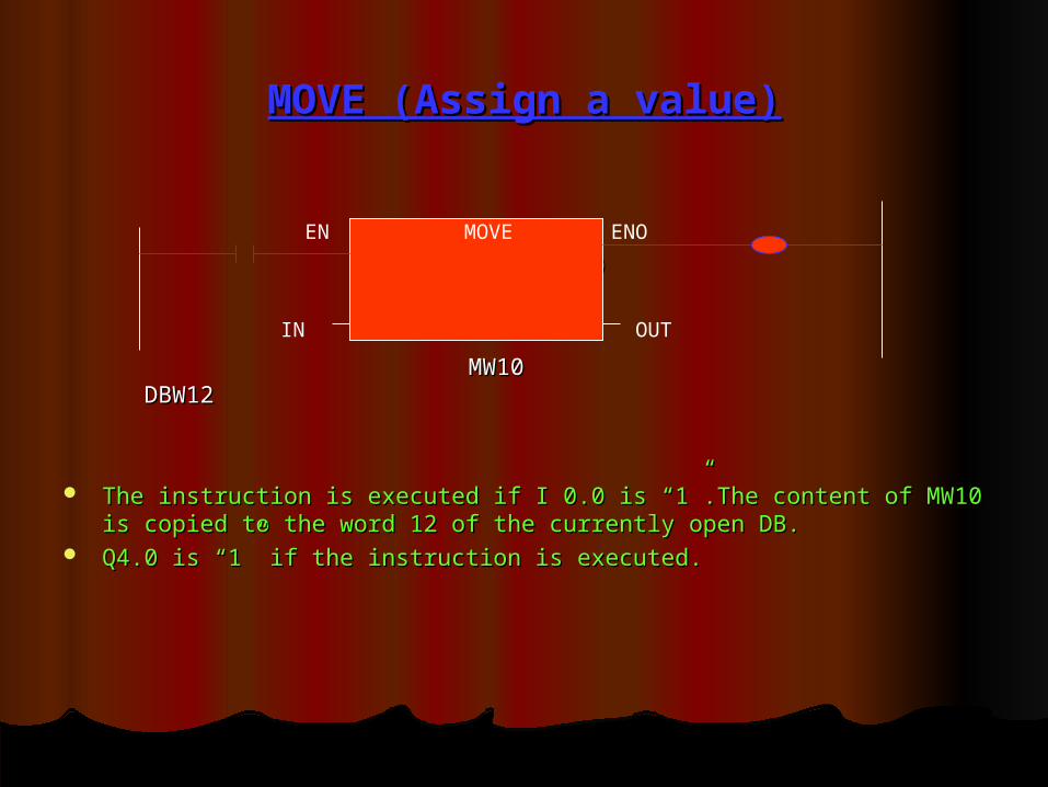
MOVE (Assign a value)MOVE (Assign a value)
I 0.0 Q4.0I 0.0 Q4.0
MW10 DBW12MW10 DBW12
The instruction is executed if I 0.0 is “1”.The content of MW10 is copied to The instruction is executed if I 0.0 is “1”.The content of MW10 is copied to the word 12 of the currently open DB.the word 12 of the currently open DB.
Q4.0 is “1” if the instruction is executed.Q4.0 is “1” if the instruction is executed.
EN MOVE ENO
IN OUT
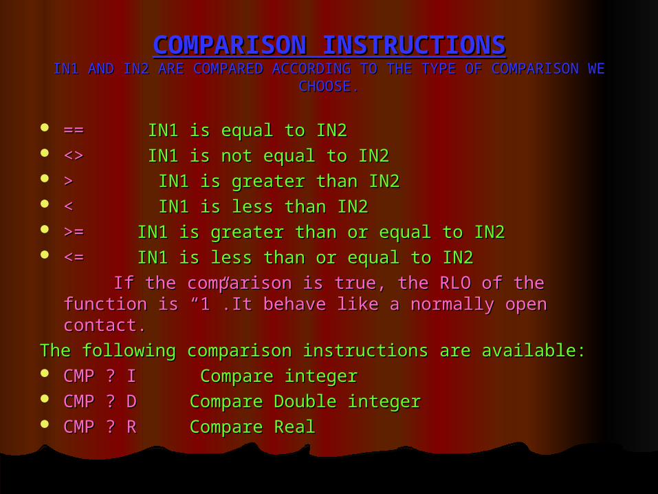
COMPARISON INSTRUCTIONSCOMPARISON INSTRUCTIONSIN1 AND IN2 ARE COMPARED ACCORDING TO THE TYPE OF COMPARISON WEIN1 AND IN2 ARE COMPARED ACCORDING TO THE TYPE OF COMPARISON WE
CHOOSE.CHOOSE.
== == IN1 is equal to IN2 IN1 is equal to IN2 <> <> IN1 is not equal to IN2 IN1 is not equal to IN2 > > IN1 is greater than IN2 IN1 is greater than IN2 < < IN1 is less than IN2 IN1 is less than IN2 >=>= IN1 is greater than or equal to IN2 IN1 is greater than or equal to IN2 <=<= IN1 is less than or equal to IN2 IN1 is less than or equal to IN2
If the comparison is true, the RLO of the function is “1”.It If the comparison is true, the RLO of the function is “1”.It behave like a normally open contact.behave like a normally open contact.
The following comparison instructions are available:The following comparison instructions are available: CMP ? ICMP ? I Compare integer Compare integer CMP ? DCMP ? D Compare Double integer Compare Double integer CMP ? RCMP ? R Compare Real Compare Real
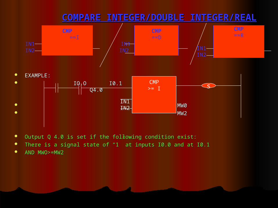
COMPARE INTEGER/DOUBLE INTEGER/REALCOMPARE INTEGER/DOUBLE INTEGER/REALCMP
==IIN1 IN2
s
EXAMPLE:EXAMPLE: IO.O I0.1 Q4.0IO.O I0.1 Q4.0
MW0MW0 MW2MW2
Output Q 4.0 is set if the following condition exist:Output Q 4.0 is set if the following condition exist: There is a signal state of “1” at inputs I0.0 and at I0.1There is a signal state of “1” at inputs I0.0 and at I0.1 AND MWO>=MW2AND MWO>=MW2
CMP>= I
IN1 IN2
CMP==D
IN1 IN2
CMP==R
IN1 IN2
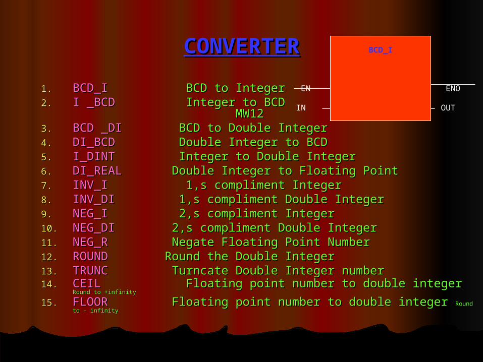
CONVERTERCONVERTER
1.1. BCD_I BCD_I BCD to Integer BCD to Integer2.2. I _BCDI _BCD Integer to BCD MW10 Integer to BCD MW10
MW12MW123.3. BCD _DIBCD _DI BCD to Double Integer BCD to Double Integer4.4. DI_BCD DI_BCD Double Integer to BCD Double Integer to BCD5.5. I_DINT I_DINT Integer to Double Integer Integer to Double Integer6.6. DI_REALDI_REAL Double Integer to Floating Point Double Integer to Floating Point7.7. INV_I INV_I 1,s compliment Integer 1,s compliment Integer8.8. INV_DIINV_DI 1,s compliment Double Integer 1,s compliment Double Integer9.9. NEG_I NEG_I 2,s compliment Integer 2,s compliment Integer10.10. NEG_DINEG_DI 2,s compliment Double Integer 2,s compliment Double Integer11.11. NEG_R NEG_R Negate Floating Point Number Negate Floating Point Number12.12. ROUND ROUND Round the Double Integer Round the Double Integer13.13. TRUNC TRUNC Turncate Double Integer number Turncate Double Integer number14.14. CEIL CEIL Floating point number to double integer Floating point number to double integer Round to +infinityRound to +infinity
15.15. FLOOR FLOOR Floating point number to double integer Floating point number to double integer Round to - infinityRound to - infinity
BCD_I
EN ENO
IN OUT
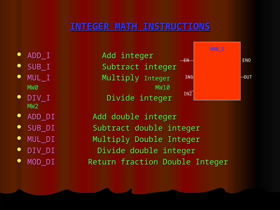
INTEGER MATH INSTRUCTIONSINTEGER MATH INSTRUCTIONS
ADD_I ADD_I Add integer Add integer SUB_I SUB_I Subtract integer Subtract integer MUL_I MUL_I Multiply Multiply Integer MW0Integer MW0
MW10MW10 DIV_I DIV_I Divide integer Divide integer MW2MW2
ADD_DI ADD_DI Add double integer Add double integer SUB_DI SUB_DI Subtract double integer Subtract double integer MUL_DIMUL_DI Multiply Double Integer Multiply Double Integer DIV_DI DIV_DI Divide double integer Divide double integer MOD_DI MOD_DI Return fraction Double Integer Return fraction Double Integer
ADD_I
EN ENO
IN1 OUT
IN2

CPUsCPUs
CPUs are capable of handling 85 K statements and 256 K CPUs are capable of handling 85 K statements and 256 K data the main memory up to 512 KB.data the main memory up to 512 KB.
Various CPUs provide up to 8192 bit memories,512 timers, Various CPUs provide up to 8192 bit memories,512 timers, and 512 counter.and 512 counter.
Smaller CPUs can be expanded up to 256 DI/DO or 64AI/AO.Smaller CPUs can be expanded up to 256 DI/DO or 64AI/AO. Larger CPUs can be expanded up to 1024 DI/DO or 256 AI/AO.Larger CPUs can be expanded up to 1024 DI/DO or 256 AI/AO. Up-down counters acquire pulses up to 10 kHz.Up-down counters acquire pulses up to 10 kHz. With a frequency measurement up to 10 kHz motor speed With a frequency measurement up to 10 kHz motor speed
can be accurately measured.can be accurately measured. For application involving controller of pressure, temperature For application involving controller of pressure, temperature
or flow rates the integrated PID controllers can e or flow rates the integrated PID controllers can e parameterized.parameterized.
The most powerful S7-300 CPU is also available with an The most powerful S7-300 CPU is also available with an integrated PROFIBUS-DP interface.integrated PROFIBUS-DP interface.

CPUs--- control & display elementsCPUs--- control & display elements
STATUS AND FAULT DISPLEYS:STATUS AND FAULT DISPLEYS:
SF………….RED HARDWARE OR SOFTWARE FAULTSSF………….RED HARDWARE OR SOFTWARE FAULTS
BATF………RED BATTERY FAULTBATF………RED BATTERY FAULT
DC5V….....GREEN 5 VDC SUPPLY FOR CPU AND S7-300 BUS IS OK.DC5V….....GREEN 5 VDC SUPPLY FOR CPU AND S7-300 BUS IS OK.
FRCE……..YELLOW FORCE REQUEST IS ACTIVE.FRCE……..YELLOW FORCE REQUEST IS ACTIVE.
RUN……...GREEN CPU IN RUN; LED FLASHES AT START-UP WITH 1 HZ.RUN……...GREEN CPU IN RUN; LED FLASHES AT START-UP WITH 1 HZ.
STOP……..YELLOW CPU IN STOP OR HOLD OR START-UPSTOP……..YELLOW CPU IN STOP OR HOLD OR START-UP..
MODE SELECTOR SWITCH:MODE SELECTOR SWITCH:
RUN-P The CPU scans the user program. The key can not be removed.RUN-P The CPU scans the user program. The key can not be removed.
RUN mode The CPU scans the user key can be removed.RUN mode The CPU scans the user key can be removed.
STOP mode The CPU does not scan user program. The key can be removed to prevent STOP mode The CPU does not scan user program. The key can be removed to prevent anyone anyone
from changing the operating mode.from changing the operating mode.
MRES mode Resetting the memory using the mode selector requires a special sequence of MRES mode Resetting the memory using the mode selector requires a special sequence of
operations.operations.

PLC SELECTION CRITERIAPLC SELECTION CRITERIA
NUMBER OF INPUTS………DIGITAL / ANALOGNUMBER OF INPUTS………DIGITAL / ANALOG NUMBER OF OUTPUTS……DIGITAL/ANALOGNUMBER OF OUTPUTS……DIGITAL/ANALOG MEMORYMEMORY PROCESSING SPEED OF CPU.PROCESSING SPEED OF CPU. CPU CAPABILITIES/SYSTEM FUNCTIONS/SYSTEM FUNCTION CPU CAPABILITIES/SYSTEM FUNCTIONS/SYSTEM FUNCTION
BLOCKS.BLOCKS. NO. OF TIMERS,COUNTERS & SIZE OF BIT NO. OF TIMERS,COUNTERS & SIZE OF BIT
MEMORY,FLAGS(MARKERS).MEMORY,FLAGS(MARKERS). NEED OF SPECIAL FUNCTION MODULES SUCH AS HIGH NEED OF SPECIAL FUNCTION MODULES SUCH AS HIGH
SPEED COUNTERS,CLOSED LOOP CONTROL ETC.SPEED COUNTERS,CLOSED LOOP CONTROL ETC. NEED OF INTERFACE MODULE.NEED OF INTERFACE MODULE. NETWORKING AND COMMUNICATION CAPABILITIES.NETWORKING AND COMMUNICATION CAPABILITIES.

CYCLIC PROGRAM EXECUTIONCYCLIC PROGRAM EXECUTION
Start-up block (OB100)…………execute once.Start-up block (OB100)…………execute once. Start the cycle monitoring time.Start the cycle monitoring time. Reading the signal states from the modules and saving the Reading the signal states from the modules and saving the
data indata in
the PII (Process Image Inputs).the PII (Process Image Inputs). Execution of the program in OB1(cyclic execution)….events, Execution of the program in OB1(cyclic execution)….events,
time of the day, hardware interrupts etc., call others OBs , time of the day, hardware interrupts etc., call others OBs , FBs , FCs / PBs etc.FBs , FCs / PBs etc.
Writing the process image output (PIQ) to the output Writing the process image output (PIQ) to the output modules.modules.
PII OB1 PIQPII OB1 PIQ
SOETWARE & VERSIONSOETWARE & VERSION
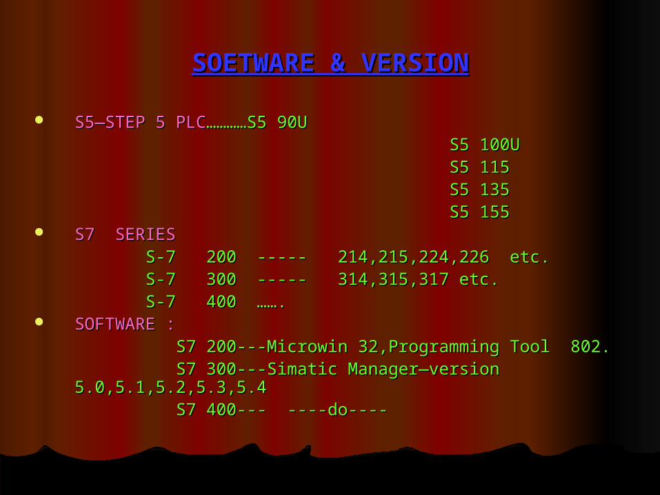
S5—STEP 5 PLCS5—STEP 5 PLC…………S5 90U…………S5 90U S5 100US5 100U S5 115S5 115 S5 135S5 135 S5 155S5 155 S7 SERIESS7 SERIES S-7 200 ----- 214,215,224,226 etc.S-7 200 ----- 214,215,224,226 etc. S-7 300 ----- 314,315,317 etc.S-7 300 ----- 314,315,317 etc. S-7 400 …….S-7 400 ……. SOFTWARE :SOFTWARE : S7 200---Microwin 32,Programming Tool 802.S7 200---Microwin 32,Programming Tool 802. S7 300---Simatic Manager—version 5.0,5.1,5.2,5.3,5.4S7 300---Simatic Manager—version 5.0,5.1,5.2,5.3,5.4 S7 400--- ----do----S7 400--- ----do----
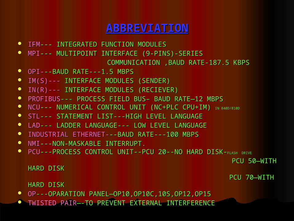
ABBREVIATIONABBREVIATION IFMIFM--- INTEGRATED FUNCTION MODULES--- INTEGRATED FUNCTION MODULES MPIMPI--- MULTIPOINT INTERFACE (9-PINS)-SERIES--- MULTIPOINT INTERFACE (9-PINS)-SERIES COMMUNICATION ,BAUD RATE-187.5 KBPSCOMMUNICATION ,BAUD RATE-187.5 KBPS OPI-OPI---BAUD RATE---1.5 MBPS--BAUD RATE---1.5 MBPS IM(S)---IM(S)--- INTERFACE MODULES (SENDER) INTERFACE MODULES (SENDER) IN(R)---IN(R)--- INTERFACE MODULES (RECIEVER) INTERFACE MODULES (RECIEVER) PROFIBUSPROFIBUS--- PROCESS FIELD BUS– BAUD RATE—12 MBPS--- PROCESS FIELD BUS– BAUD RATE—12 MBPS NCUNCU--- NUMERICAL CONTROL UNIT (NC+PLC CPU+IM) --- NUMERICAL CONTROL UNIT (NC+PLC CPU+IM) IN 840D/810DIN 840D/810D
STLSTL--- STATEMENT LIST---HIGH LEVEL LANGUAGE--- STATEMENT LIST---HIGH LEVEL LANGUAGE LADLAD--- LADDER LANGUAGE--- LOW LEVEL LANGUAGE--- LADDER LANGUAGE--- LOW LEVEL LANGUAGE INDUSTRIAL ETHERNET-INDUSTRIAL ETHERNET---BAUD RATE---100 MBPS--BAUD RATE---100 MBPS NMINMI---NON-MASKABLE INTERRUPT.---NON-MASKABLE INTERRUPT. PCUPCU---PROCESS CONTROL UNIT--PCU 20--NO HARD DISK----PROCESS CONTROL UNIT--PCU 20--NO HARD DISK-FLASHFLASH DRIVEDRIVE
PCU 50—WITH HARD DISKPCU 50—WITH HARD DISK PCU 70—WITH HARD DISKPCU 70—WITH HARD DISK OPOP---OPARATION PANEL—OP10,OP10C,10S,OP12,OP15---OPARATION PANEL—OP10,OP10C,10S,OP12,OP15 TWISTED PAIRTWISTED PAIR—-TO PREVENT EXTERNAL INTERFERENCE—-TO PREVENT EXTERNAL INTERFERENCE

STEP 7 “BLOCKS”STEP 7 “BLOCKS”
1.1. USER PROGRAMMABLE BLOCK-USER PROGRAMMABLE BLOCK---------1.ORGANISATION BLOCK (OB)1.ORGANISATION BLOCK (OB)
2.FUNCTIONS (FCs)2.FUNCTIONS (FCs)
3.FUNCTION BLOCK (FBs)3.FUNCTION BLOCK (FBs)
2.2. DATA BLOCK(DB)DATA BLOCK(DB) ---- ----1. SHARED BLOCK1. SHARED BLOCK
2. INSTANT BLOCK 2. INSTANT BLOCK
3.3. PROGRAMMED READY TO USE BLOCK-PROGRAMMED READY TO USE BLOCK-----IN S7 LIBRARY----IN S7 LIBRARY IN CPU—IN CPU—SYSTEM FUNCTION SYSTEM FUNCTION
1. SFC1. SFC
2. SFB2. SFB
NOTE:NOTE: USER CAN CALL FC & FB THROUGH PROGRAM USER CAN CALL FC & FB THROUGH PROGRAM
OB1 –ONLY CALLED BY CPUOB1 –ONLY CALLED BY CPU
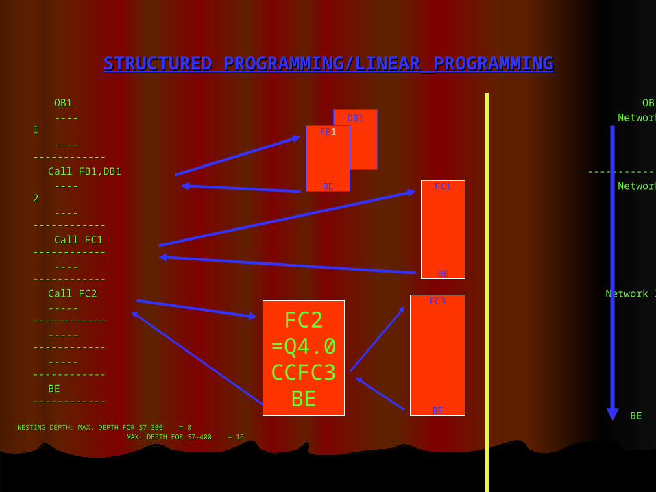
STRUCTURED PROGRAMMING/LINEARSTRUCTURED PROGRAMMING/LINEAR PROGRAMMINGPROGRAMMING
OB1 OB 1OB1 OB 1
---- Network 1---- Network 1
---- ---------------- ------------
Call FB1,DB1 ------------Call FB1,DB1 ------------
---- Network 2---- Network 2
---- ---------------- ------------
Call FC1 ------------Call FC1 ------------
---- ---------------- ------------
Call FC2 Network 3Call FC2 Network 3
----- ----------------- ------------
----- ----------------- ------------
----- ----------------- ------------
BE ------------BE ------------
BEBENESTING DEPTH: MAX. DEPTH FOR S7-300 = 8NESTING DEPTH: MAX. DEPTH FOR S7-300 = 8
MAX. DEPTH FOR S7-400 = 16MAX. DEPTH FOR S7-400 = 16
DB1
FB1
BE FC1
BE
FC2=Q4.0CCFC3
BE
FC3
BE
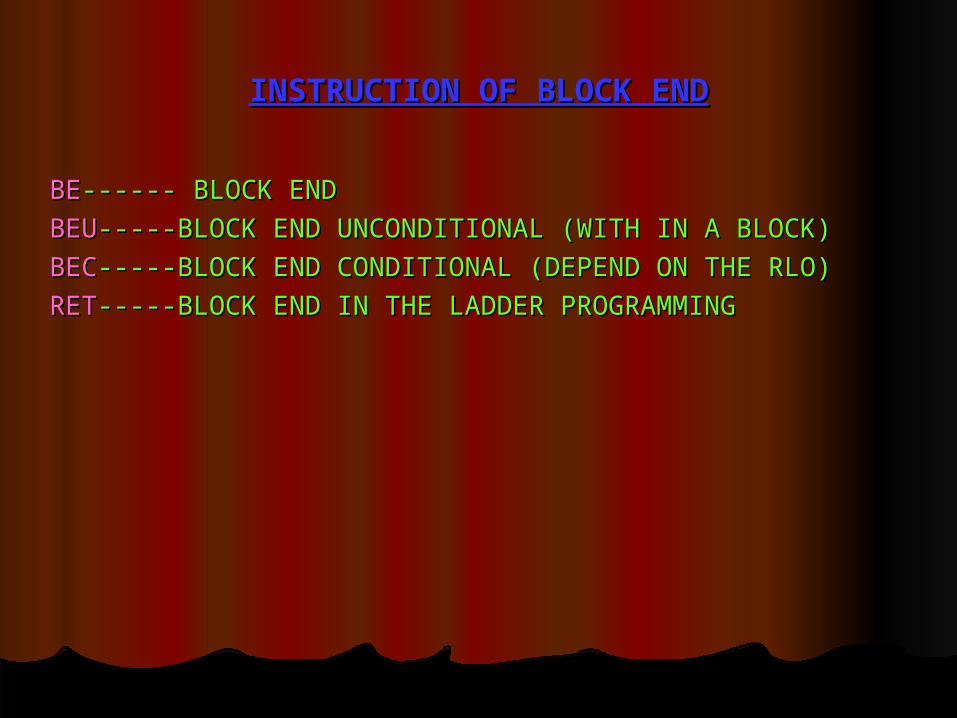
INSTRUCTION OF BLOCK ENDINSTRUCTION OF BLOCK END
BEBE------ BLOCK END------ BLOCK END
BEUBEU-----BLOCK END UNCONDITIONAL (WITH IN A BLOCK)-----BLOCK END UNCONDITIONAL (WITH IN A BLOCK)
BECBEC-----BLOCK END CONDITIONAL (DEPEND ON THE RLO)-----BLOCK END CONDITIONAL (DEPEND ON THE RLO)
RETRET-----BLOCK END IN THE LADDER PROGRAMMING-----BLOCK END IN THE LADDER PROGRAMMING

ANALOG SIGNAL PROCESSINGANALOG SIGNAL PROCESSING
TEMP.TEMP.
PRESSUREPRESSURE
FLOW SENSOR ELECTRICAL SIGNAL FLOW SENSOR ELECTRICAL SIGNAL STANDARD PROCESSABLE STANDARD PROCESSABLE SIGNALSIGNAL
LEVELLEVEL
--------------
--------------
MEASURING RANGE
MODULE(MR)
D/APROCESSIMAGE WEIGHT
(PIW)
CPU


![[IT] PLC Checker presentation](https://static.fdocuments.us/doc/165x107/55aa6b061a28ab78398b4672/it-plc-checker-presentation.jpg)