Preliminary June 2008 IL42-4032A - fccid.io · Elster Raleigh, North Carolina USA ... For...
22
June 2008 IL42-4032A Elster Raleigh, North Carolina USA +1 800 338 5251 (US toll free) +1 905 634 4895 (Canada) [email protected] www.elsterelectricity.com A3 ALPHA ® Meters with External Antenna Capability For use with the ILC2 option board General Typically, the internal antenna used with the ILC2 option board is sufficient for reliable communication with the EnergyAxis network. However, if the A3 ALPHA meter is enclosed in a meter service cabinet or the antenna must be mounted higher to overcome signal obstruction, an external antenna may be used. This leaflet contains general information for installing the A3 ALPHA meter equipped with connections for an external antenna. ■ For information on the operation of the A3 ALPHA meter, see the A3 ALPHA Meter Technical Manual (TM42- 2190B or later) or the A3 ALPHA Meter Technical Manual For Use in Canada (TM42-2195A or later) ■ For information on installing the A3 ALPHA meter, see the “ALPHA Meter Installation Instructions” (IL42- 4001Q or later) WARNING ! Use authorized utility procedures to install and service metering equipment. Dangerous voltages are present. Equipment damage, personal injury, or death can result if safety precautions are not followed. Use circuit closing devices on current transformer secondaries (3S, 4S, 5S, 5A, 6S, 6A, 8S, 9S, 10S, 10A, 26S, 29S, 35S, 35A, 36S, and 36A meters). Equipment damage, personal injury, or death can result if circuit closing secondaries are not used. Connecting an External Antenna Note. This device has been designed to operate with the antennas listed below and having a maximum gain of 5.15 dBi. Antennas not included in this list or having a gain greater than 5.15 dBi are strictly prohibited for use with this device. The required antenna impedance is 50 ohms. Internal antenna: Elster Electricity P/N: 1B12150H01 Local external antennas: Laird/Antenex TRA(B)9023P 1 (3.1 dBi); Laird/Antenex TRA(B)9023NP (3.1 dBi) Remote external antennas: PCTEL/MAXRAD P/N MFB9150 (Tessco P/N 39493) for unity gain (2.15 dBi); PCTEL/ MAXRAD P/N MFB 9153 for 3 dB gain (5.15 dBi) The external antenna connects to the ILC2 option board using a connector lead as shown in Figure 1. In addition to the standard internal antenna, there are two options available for connecting an external antenna: ■ Local external antenna ■ Remote external antenna 1 Part number specifies an antenna with a black body. For an antenna with a white body, use part number TRA9023P. Preliminary
Transcript of Preliminary June 2008 IL42-4032A - fccid.io · Elster Raleigh, North Carolina USA ... For...
June 2008 IL42-4032A
Elster Raleigh, North Carolina USA+1 800 338 5251 (US toll free)+1 905 634 4895 (Canada)[email protected]
A3 ALPHA® Meters with External Antenna Capability
For use with the ILC2 option board
GeneralTypically, the internal antenna used with the ILC2 option board is sufficient for reliable communication with the EnergyAxis network. However, if the A3 ALPHA meter is enclosed in a meter service cabinet or the antenna must be mounted higher to overcome signal obstruction, an external antenna may be used.
This leaflet contains general information for installing the A3 ALPHA meter equipped with connections for an external antenna.
■ For information on the operation of the A3 ALPHA meter, see the A3 ALPHA Meter Technical Manual (TM42-2190B or later) or the A3 ALPHA Meter Technical Manual For Use in Canada (TM42-2195A or later)
■ For information on installing the A3 ALPHA meter, see the “ALPHA Meter Installation Instructions” (IL42-4001Q or later)
WARNING!
Use authorized utility procedures to install and service metering equipment. Dangerous voltages are present. Equipment damage, personal injury, or death can result if safety precautions are not followed.Use circuit closing devices on current transformer secondaries (3S, 4S, 5S, 5A, 6S, 6A, 8S, 9S, 10S, 10A, 26S, 29S, 35S, 35A, 36S, and 36A meters). Equipment damage, personal injury, or death can result if circuit closing secondaries are not used.
Connecting an External AntennaNote. This device has been designed to operate with the antennas listed below and having a maximum gain of 5.15 dBi. Antennas not included in this list or having a gain greater than 5.15 dBi are strictly prohibited for use with this device. The required antenna impedance is 50 ohms.
Internal antenna: Elster Electricity P/N: 1B12150H01
Local external antennas: Laird/Antenex TRA(B)9023P1 (3.1 dBi); Laird/Antenex TRA(B)9023NP (3.1 dBi)
Remote external antennas: PCTEL/MAXRAD P/N MFB9150 (Tessco P/N 39493) for unity gain (2.15 dBi); PCTEL/MAXRAD P/N MFB 9153 for 3 dB gain (5.15 dBi)
The external antenna connects to the ILC2 option board using a connector lead as shown in Figure 1. In addition to the standard internal antenna, there are two options available for connecting an external antenna:
■ Local external antenna
■ Remote external antenna
1 Part number specifies an antenna with a black body. For an antenna with a white body, use part number TRA9023P.
Preliminary

IL42-4032A June 2008
2
Figure 1. Retaining clip and connector lead
Local External AntennaIf the A3 ALPHA meter is used in a metal service cabinet, using a local external antenna may be necessary. To obtain better coverage, the local external antenna can be mounted on the top of the metal service cabinet or the meter socket enclosure (see [1] in Figure 2).
Elster recommends Antenex Inc.’s 902-928 MHz Permanent Mount antenna (TRAB9023P).1 To mount the antenna on the service cabinet or meter socket enclosure, drill a 5/8-inch hole into the cabinet wall with a step drill. Insert the antenna through the hole. After the antenna is mounted, the antenna’s Type N female connector can be mated with the meter’s Type N male connector.
For installations where the mounting for the local antenna does not provide a conductive metallic ground plane, the Antenex TRAB9023NP (no ground plane required) may be employed. The gain and pattern are virtually identical with the TRAB9023P version and the TRAB9023NP may also be employed on metallic ground planes with good results.
Remote External AntennaIf the A3 ALPHA meter is used in a metal building, or the meter is installed in a location where the site requires an antenna at a greater height to overcome blocked signals, a remote antenna may be required. If a remote external antenna is used, a lightning/surge arrestor should be installed at the bottom of the socket enclosure (see [2] in Figure 2). Elster recommends a PolyPhaser DSXL IN-LINE EMP surge filter (Tessco P/N 491574).2
NOTICEDo not use a standard RG-8/U cable with solid polyethylene dielectric. The losses in solid dielectric RG-8/U cables in short distances make solid dielectric RG-8/U cables unacceptable.
The most economical connection to the remote external antenna is the RG-8/U “foam” or “LMR-400” type cable. This type of cable should be suitable for distances of up to 100 feet. The foam dielectric cable will incur a loss of approximately 3.9 dB in 100 feet (or approximately 2 dB in 50 feet). The coaxial cable should be mounted at the bottom of the meter socket in “drip loop” fashion. A “drip loop” is formed by bringing the coaxial cable to a point below the meter socket and then bending it back up to the connector. This forms a U-shape, which allows water to run down the cable exterior. Antenna cables should be ordered with N-type male connectors on each end.
1 Antenex, 2000-205 Bloomingdale Road, Glendale Heights IL 60131. Telephone: 630-351-9007. Website: antenex.com2 PolyPhaser Corporation, 2225 Park Place, Minden, NV 89423. Telephone: 800-325-7170.
Website: polyphaser.com.
N-type connector to external antenna
Connector lead
External antenna connection lead
Wire tie
Retaining clip
Preliminary

June 2008 IL42-4032A
3
The collectors and nodes in the EnergyAxis System operate under Part 15.247 of the FCC Rules. Suitable antennas are omni-directional antennas of unity gain or 3 dB gain (2.15 and 5.15 dBi, respectively). Elster recommends the following, which are rated to withstand 100 mph winds and are fitted with Type N female connectors:
■ PCTEL/MAXRAD MFB9150 Series (Tessco P/N 39493) for unity gain (2.15 dBi)
■ PCTEL/MAXRAD MFB9153 Series (Tessco P/N 74330) for 3 dB gain (5.15 dBi)
Regardless of the antenna selected, the antenna should be mounted with at least two MMK1 pipe clamps (Tessco SKU 68869). The antenna should be mounted in the clear, as free from the conductive or metallic obstructions as possible. The connectors should be sealed for waterproofing.
Figure 2. External antenna options
Remote antenna materials described in this IL can be obtained from the following:
Tessco Technologies, Inc.11126 McCormick RoadHunt Valley, MD 21031-1494+1 800 508 5444tessco.com
Laird/Antenex antennas can be obtained from the following:
OEM Sales M6Laird Technologies1751 Wilkening CourtSchaumburg, IL 60173+1 847 839 6916 (telephone) or +1 847 839 6063 (fax)www.lairdtech.com
[2] Lightning/surge arrestor
N-type female connector for cable to remote external antenna
[1] External antenna
Local external antenna installation Remote external antenna installation
Preliminary

IL42-4032A June 2008
DISCLAIMER OF WARRANTIES AND LIMITATIONS OF LIABILITY
There are no understandings, agreements, representations, or warranties either express or implied, including warranties of merchantabil-ity or fitness for a particular purpose, other than those specifically set out by any existing contract between the parties. Any such con-tract states the entire obligation of the seller. The contents of this document shall not become part of or modify any prior existing agreement, commitment, or relationship.The information, recommendations, descriptions, and safety notices in this document are based on Elster Electricity, LLC experience and judgment with respect to operation and maintenance of the described product. This information should not be considered as all-inclusive or covering all contingencies. If further information is required, Elster Electricity, LLC should be consulted.
No warranties, either expressed or implied, including warranties of fitness for a particular purpose or merchantability, or warranties arising from the course of dealing or usage of trade, are made regarding the information, recommendations, descriptions, warnings, and cau-tions contained herein.In no event will Elster Electricity, LLC be responsible to the user in contract, in tort (including negligence), strict liability or otherwise for any special, indirect, incidental, or consequential damage or loss whatsoever, including but not limited to: damage or loss of use of equipment, cost of capital, loss of profits or revenues, or claims against the user by its customers resulting from the use of the informa-tion, recommendations, descriptions, and safety notices contained herein.
Elster Electricity, LLCRaleigh, North Carolina USA ����������
*IL42-4032A*
© 2008 by Elster Electricity, LLC.All rights reserved.Printed in the United States.
FCC and Industry Canada ComplianceUser Information (Part 15.105)
This equipment has been tested and found to comply with the limits for a Class B digital device, pursuant to part 15 of the FCC Rules. These limits are designed to provide reasonable protection against harmful interference in a residential installation. This equipment generates, uses and can radiate radio frequency energy and, if not installed and used in accordance with the instructions, may cause harmful interference to radio communications. However, there is no guarantee that interference will not occur in a particular installation. If this equipment does cause harmful interference to radio or television reception, which can be determined by turning the equipment off and on, the user is encouraged to try to correct the interference by one or more of the following measures:
• reorient or relocate the receiving antenna
• increase the separation between the equipment and the receiver
• connect the equipment into an outlet on a circuit different from that to which the receiver is connected
• consult the dealer or an experienced radio/TV technician for help
If you experience trouble with this equipment, please use the Return Material Request (RMR) feature available at the Online Customer Services at www.elsterelectricity.com. Do not attempt to repair this equipment yourself unless you are replacing the entire module.
Compliance Statement (Part 15.19)
The ILC2 option board complies with Part 15 of the FCC Rules and with RSS-210 of Industry Canada. Operation is subject to the following two conditions:
1. this device may not cause harmful interference, and
2. this device must accept any interference received, including interference that may cause undesired operation of the device
Antenna Compliance
To reduce potential interference to other users, the antenna type and its gain should be so chosen that the equivalent isotropically radiated power (e.i.r.p.) is not more than permitted for successful communication.
Warning (Part 15.21)
Changes or modifications not expressly approved by Elster Electricity could void the user’s authority to operate the equipment.
RF Radiation Safety Guidelines
The device should be installed in a location where there will be a separation greater than 20 cm (8 inches) from locations occupied by humans.
Collocation Statement
Collocation of simultaneously-transmitting (co-transmitting) antennas located within 20 cm of each other within a final product is not allowed.
Preliminary
A3 ALPHA® Meter/Node (ILC2)
Product GuidePG42-1017A
DRAFT
© 2008 by Elster. All rights are reserved.
No part of this software or documentation may be reproduced, transmitted, processed or recorded by any means or form, electronic, mechanical, photographic or otherwise, translated to another language, or be released to any third party without the express written consent of Elster.
Printed in the United States of America.
ALPHA, ALPHA Plus, EnergyAxis, and REX are registered trademarks; and Metercat, AlphaPlus, and REX2 are trademarks of Elster.Other product and company names mentioned herein may be the trademarks and/or registered trademarks of their respective owners.
DISCLAIMER OF WARRANTIES AND LIMITATIONS OF LIABILITY
There are no understandings, agreements, representations, or warranties either expressed or implied, including warranties of merchantability or fitness for a particular purpose, other than those specifically set out by any existing contract between the parties. Any such contract states the entire obligation of the seller. The contents of this document shall not become part of or modify any prior existing agreement, commitment, or relationship.
The information, recommendations, descriptions, and safety notices in this document are based on Elster experience and judgment with respect to operation and maintenance of the described product. This information should not be considered as all-inclusive or covering all contingencies. If further information is required, Elster should be consulted.
No warranties, either expressed or implied, including warranties of fitness for a particular purpose or merchantability, or warranties arising from the course of dealing or usage of trade, are made regarding the information, recommendations, descriptions, warnings, and cautions contained herein.
In no event will Elster be responsible to the user in contract, in tort (including negligence), strict liability or otherwise for any special, indirect, incidental, or consequential damage or loss whatsoever, including but not limited to: damage or loss of use of equipment, cost of capital, loss of profits or revenues, or claims against the user by its customers resulting from the use of the information, recommendations, descriptions, and safety notices contained herein.
DRAFT

A3 ALPHA Meter/Node (ILC2)June 2008 Product Guide
i
Contents General Description . . . . . . . . . . . . . . . . . . . . . . . . . . . . . . . . . . . . 1
A3 ALPHA Meter Circuit Board . . . . . . . . . . . . . . . . . . . . . . . . . . . . 1
Metercat Programming Note . . . . . . . . . . . . . . . . . . . . . . . . . . . . . . . . . . . . . . . . . . . .3
Metering Software and System. . . . . . . . . . . . . . . . . . . . . . . . . . . . 4
Metercat . . . . . . . . . . . . . . . . . . . . . . . . . . . . . . . . . . . . . . . . . . . . . . . . . . . . . . . . . . . .4
EnergyAxis Metering Automation Server. . . . . . . . . . . . . . . . . . . . . . . . . . . . . . . . . . .4
Operation of the A3 ALPHA Meter with ILC2 Option Board . . . . . . 4
Billing Date . . . . . . . . . . . . . . . . . . . . . . . . . . . . . . . . . . . . . . . . . . . . . . . . . . . . . . . . . .4
TOU Schedules . . . . . . . . . . . . . . . . . . . . . . . . . . . . . . . . . . . . . . . . . . . . . . . . . . . . . . .5
Season Changes . . . . . . . . . . . . . . . . . . . . . . . . . . . . . . . . . . . . . . . . . . . . . . . . . . . . . .5
Power Failure and Restoration. . . . . . . . . . . . . . . . . . . . . . . . . . . . . . . . . . . . . . . . . . .5
ILC2 Option Board Configuration. . . . . . . . . . . . . . . . . . . . . . . . . . . . . . . . . . . . . . . . .5
Short data format . . . . . . . . . . . . . . . . . . . . . . . . . . . . . . . . . . . . . . . . . . . . . .5
Long data format . . . . . . . . . . . . . . . . . . . . . . . . . . . . . . . . . . . . . . . . . . . . . .6
Reading the A3 ALPHA Meter . . . . . . . . . . . . . . . . . . . . . . . . . . . . . 6
Changing an A3 ALPHA Meter. . . . . . . . . . . . . . . . . . . . . . . . . . . . . 6
Display List Items . . . . . . . . . . . . . . . . . . . . . . . . . . . . . . . . . . . . . . 7
ILC2 Option Board Error Codes . . . . . . . . . . . . . . . . . . . . . . . . . . . . . . . . . . . . . . . . . .7
No error . . . . . . . . . . . . . . . . . . . . . . . . . . . . . . . . . . . . . . . . . . . . . . . . . . . . .7
Table CRC error . . . . . . . . . . . . . . . . . . . . . . . . . . . . . . . . . . . . . . . . . . . . . . .8
General configuration error . . . . . . . . . . . . . . . . . . . . . . . . . . . . . . . . . . . . . . .8
Shared memory error . . . . . . . . . . . . . . . . . . . . . . . . . . . . . . . . . . . . . . . . . . .8
Power fail data save error . . . . . . . . . . . . . . . . . . . . . . . . . . . . . . . . . . . . . . . .8
ILC2 Option Board Status Codes. . . . . . . . . . . . . . . . . . . . . . . . . . . . . . . . . . . . . . . . .8
No status . . . . . . . . . . . . . . . . . . . . . . . . . . . . . . . . . . . . . . . . . . . . . . . . . . . .8
Node is registered. . . . . . . . . . . . . . . . . . . . . . . . . . . . . . . . . . . . . . . . . . . . . .8
Demand reset scheduled . . . . . . . . . . . . . . . . . . . . . . . . . . . . . . . . . . . . . . . .8
ILC2 Option Board Information . . . . . . . . . . . . . . . . . . . . . . . . . . . . . . . . . . . . . . . . . .9
LAN ID 1 . . . . . . . . . . . . . . . . . . . . . . . . . . . . . . . . . . . . . . . . . . . . . . . . . . . . .9
LAN ID 2 . . . . . . . . . . . . . . . . . . . . . . . . . . . . . . . . . . . . . . . . . . . . . . . . . . . . .9
Utility ID . . . . . . . . . . . . . . . . . . . . . . . . . . . . . . . . . . . . . . . . . . . . . . . . . . . . .9
Network registration status . . . . . . . . . . . . . . . . . . . . . . . . . . . . . . . . . . . . . . .9
FCC and Industry Canada Compliance . . . . . . . . . . . . . . . . . . . . . . 9
Compliance Statement (Part 15.19) . . . . . . . . . . . . . . . . . . . . . . . . . . . . . . . . . . . . . . .9
Warning (Part 15.21) . . . . . . . . . . . . . . . . . . . . . . . . . . . . . . . . . . . . . . . . . . . . . . . . . .10
RF Radiation Safety Guidelines per Part 2 of FCC Rules and Regulations . . . . . . .10
User Information (Part 15.105) . . . . . . . . . . . . . . . . . . . . . . . . . . . . . . . . . . . . . . . . . .10
Industry Canada Statement . . . . . . . . . . . . . . . . . . . . . . . . . . . . . . . . . . . . . . . . . . . .10
Collocation Statement . . . . . . . . . . . . . . . . . . . . . . . . . . . . . . . . . . . . . . . . . . . . . . . .10
Technical Specifications. . . . . . . . . . . . . . . . . . . . . . . . . . . . . . . . 11
Operating Ranges . . . . . . . . . . . . . . . . . . . . . . . . . . . . . . . . . . . . . . . . . . . . . . . . . . . .11
DRAFT

A3 ALPHA Meter/Node (ILC2)Product Guide June 2008
ii
DRAFT
A3 ALPHA Meter/Node (ILC2)June 2008 Product Guide
1
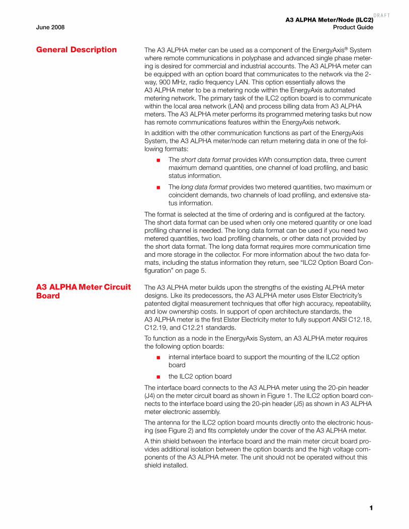
General Description The A3 ALPHA meter can be used as a component of the EnergyAxis® System where remote communications in polyphase and advanced single phase meter-ing is desired for commercial and industrial accounts. The A3 ALPHA meter can be equipped with an option board that communicates to the network via the 2-way, 900 MHz, radio frequency LAN. This option essentially allows the A3 ALPHA meter to be a metering node within the EnergyAxis automated metering network. The primary task of the ILC2 option board is to communicate within the local area network (LAN) and process billing data from A3 ALPHA meters. The A3 ALPHA meter performs its programmed metering tasks but now has remote communications features within the EnergyAxis network.
In addition with the other communication functions as part of the EnergyAxis System, the A3 ALPHA meter/node can return metering data in one of the fol-lowing formats:
■ The short data format provides kWh consumption data, three current maximum demand quantities, one channel of load profiling, and basic status information.
■ The long data format provides two metered quantities, two maximum or coincident demands, two channels of load profiling, and extensive sta-tus information.
The format is selected at the time of ordering and is configured at the factory. The short data format can be used when only one metered quantity or one load profiling channel is needed. The long data format can be used if you need two metered quantities, two load profiling channels, or other data not provided by the short data format. The long data format requires more communication time and more storage in the collector. For more information about the two data for-mats, including the status information they return, see “ILC2 Option Board Con-figuration” on page 5.
A3 ALPHA Meter Circuit Board
The A3 ALPHA meter builds upon the strengths of the existing ALPHA meter designs. Like its predecessors, the A3 ALPHA meter uses Elster Electricity’s patented digital measurement techniques that offer high accuracy, repeatability, and low ownership costs. In support of open architecture standards, the A3 ALPHA meter is the first Elster Electricity meter to fully support ANSI C12.18, C12.19, and C12.21 standards.
To function as a node in the EnergyAxis System, an A3 ALPHA meter requires the following option boards:
■ internal interface board to support the mounting of the ILC2 option board
■ the ILC2 option board
The interface board connects to the A3 ALPHA meter using the 20-pin header (J4) on the meter circuit board as shown in Figure 1. The ILC2 option board con-nects to the interface board using the 20-pin header (J5) as shown in A3 ALPHA meter electronic assembly.
The antenna for the ILC2 option board mounts directly onto the electronic hous-ing (see Figure 2) and fits completely under the cover of the A3 ALPHA meter.
A thin shield between the interface board and the main meter circuit board pro-vides additional isolation between the option boards and the high voltage com-ponents of the A3 ALPHA meter. The unit should not be operated without this shield installed.
DRAFT

A3 ALPHA Meter/Node (ILC2)Product Guide June 2008
2
Figure 1. A3 ALPHA meter electronic assembly
Figure 2. A3 ALPHA meter electronic housing with antenna
ILC2 option board at position 2
Interface board at position 1
Option board shield
Meter circuit board
Meter electronic housing
J5
J4
Antenna
DRAFT
A3 ALPHA Meter/Node (ILC2)June 2008 Product Guide
3
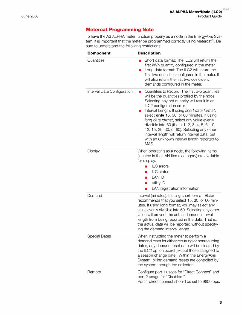
Metercat Programming NoteTo have the A3 ALPHA meter function properly as a node in the EnergyAxis Sys-tem, it is important that the meter be programmed correctly using Metercat™. Be sure to understand the following restrictions:
Component Description
Quantities ■ Short data format: The ILC2 will return the first kWh quantity configured in the meter.
■ Long data format: The ILC2 will return the first two quantities configured in the meter. It will also return the first two coincident demands configured in the meter.
Interval Data Configuration ■ Quantities to Record: The first two quantities will be the quantities profiled by the node. Selecting any net quantity will result in an ILC2 configuration error.
■ Interval Length: If using short data format, select only 15, 30, or 60 minutes. If using long data format, select any value evenly divisible into 60 (that is1, 2, 3, 4, 5, 6, 10, 12, 15, 20, 30, or 60). Selecting any other interval length will return interval data, but with an unknown interval length reported to MAS.
Display When operating as a node, the following items (located in the LAN Items category) are available for display:
■ ILC errors■ ILC status■ LAN ID■ utility ID■ LAN registration information
Demand Interval (minutes): If using short format, Elster recommends that you select 15, 30, or 60 min-utes. If using long format, you may select any value evenly divisible into 60. Selecting any other value will prevent the actual demand interval length from being reported in the data. That is, the actual data will be reported without specify-ing the demand interval length.
Special Dates When instructing the meter to perform a demand reset for either recurring or nonrecurring dates, any demand reset date will be cleared by the ILC2 option board (except those assigned to a season change date). Within the EnergyAxis System, billing demand resets are controlled by the system through the collector.
Remote1 Configure port 1 usage for “Direct Connect” and port 2 usage for “Disabled.”Port 1 direct connect should be set to 9600 bps.
DRAFT

A3 ALPHA Meter/Node (ILC2)Product Guide June 2008
4
Note. If the remote definition is not programmed into the meter, the ILC2 will not be able to return any meter reads to MAS.
The other options can be set as desired. For more information on using Meter-cat, see the Metercat user guide (TM42-2203K or later) or the online Help.
Metering Software and System
MetercatThe A3 ALPHA meter operating as a node in the EnergyAxis System requires Elster Electricity Metercat support software release 1.8 or later. Metercat offers the following features:
■ program development to create user-defined configuration data
■ meter programming to send user-defined configuration data or com-mands to the meter
■ meter reading to receive data that has been stored by the meter
■ diagnostic read including ILC2 option board and LAN status
EnergyAxis Metering Automation ServerThe EnergyAxis Metering Automation Server (MAS) reads meters over telephone or wireless networks. Using MAS, meter readings can be scheduled or per-formed on-request from the browser-based user interface. MAS allows all billing data to be read from the meter; this includes data from each A3 ALPHA meter registered with the EnergyAxis local area collector. Billing data from the A3 ALPHA meter includes consumption, demand, time-of-use registers as well as meter status flags. The A3 ALPHA meter data can be read from the stored data in the collector or on-request by using MAS to communicate through the collector to the individual A3 ALPHA meter.
Data exchange between MAS and other utility systems is performed using an open XML schema, AMR Data Exchange Format (AMRDEF), so that interfaces with billing systems and other enterprise systems can be easily implemented. MAS also comes with the JSlinger module, a powerful driver for file transfer pro-tocol (FTP) that can transform, compress and encrypt data files prior to sending them to trusted IP addresses across the Internet.
Operation of the A3 ALPHA Meter with ILC2 Option Board
The A3 ALPHA meter and the ILC2 option board communicate within the Ener-gyAxis system 900 MHz radio frequency network. The primary task of the ILC2 option board is to communicate with the LAN and to provide meter readings from the A3 ALPHA meter and pass on commands to the A3 ALPHA meter. While the time base within the A3 ALPHA meter is maintained by its super capacitor and a battery, time is adjusted automatically by the network when required.
Billing DateThe EnergyAxis System handles the billing dates for the registered A3 ALPHA meters. MAS assigns each meter to one of 30 possible billing dates, and then MAS transmits the billing dates to the meters' respective collectors. On the bill-ing date, the collector schedules the meter to perform a demand reset at the next midnight crossing.
1 If you do not see the Remote tab, select Remote as a program option in the Properties tab of your program.
DRAFT

A3 ALPHA Meter/Node (ILC2)June 2008 Product Guide
5
At midnight, the ILC2 option board copies the A3 ALPHA meter's billing data to a separate memory location. A demand reset is then performed immediately thereafter. During the next reading of all its registered meters, the collector retrieves and stores the copy of the billing data. Once the billing data is stored in the collector, it can be retrieved by MAS at the next read of the collector.
This feature allows individual meters to be identified to a specific billing date that conforms to the consumer's request or the utility's business process. Neighbor-ing meters can have individual billing dates and are not forced to be read on the same day. Changes to the billing date are handled through a schedule change in MAS.
TOU SchedulesThe A3 ALPHA meter can be programmed using Metercat to operate on a TOU program. Each program includes a TOU schedule and display list. Each TOU schedule for the A3 ALPHA meter consists of weekday, weekend, and two spe-cial day types (that is, holidays). The display list controls the values that are shown on the A3 ALPHA meter LCD. See the A3 ALPHA Meter Technical Man-ual (TM42-2190) for information on the values that can be displayed on the A3 ALPHA meter LCD.
Season ChangesSeason changes for the A3 ALPHA meter are controlled by the calendar in the A3 ALPHA meter.
Power Failure and RestorationWhen there is a power failure, the A3 ALPHA meter initiates a shutdown and stores the A3 ALPHA meter billing data and status information in EEPROM. All information stored in the ILC2 option board is stored in battery-backed RAM. The A3 ALPHA meter’s real-time clock and the data stored in the ILC2 option board are maintained by the super capacitor and battery in the A3 ALPHA meter during a power failure. If both the super capacitor and battery fail, all RAM in the meter and in the ILC2 will be lost.
Upon subsequent power restoration, an error code is generated for both the A3 ALPHA meter and the ILC2 option board.
■ For information on A3 ALPHA meter error codes, see the A3 ALPHA Meter Technical Manual (TM42-2190).
■ For information on ILC2 option board error codes, see “ILC2 Option Board Error Codes” on page 7.
ILC2 Option Board ConfigurationAt the time of ordering, the node can be configured to report register data in one of two ways:
■ short data format
■ long data format
Short data format. The short data format returns the first kWh consumption data configured in the meter, three current maximum demand quantities, identi-fication for 1 channel of load profiling, and 1 channel of load profiling to the col-lector.
■ The first demand quantity can be assigned to the maximum demand of any of the four tiers or can be assigned to the total demand.
DRAFT

A3 ALPHA Meter/Node (ILC2)Product Guide June 2008
6
■ The second demand quantity can be assigned to any of the four rates.
■ The third demand quantity can be assigned to any of the four rates.
In addition, the short data format returns the following information:
■ per phase voltages
■ A3 ALPHA meter configuration information
■ the presence of meter error or warning codes
■ number of demand resets
■ number of outages
Long data format. The long data format returns the first two metered quanti-ties configured in the meter, maximum demand or cumulative maximum demand for all rates, identification for 2 channels of load profiling, and 2 chan-nels of load profiling to the collector.
In addition, the long data format returns the following information:
■ per phase voltages
■ A3 ALPHA meter configuration
■ specific meter error or warning code
■ number of demand resets
■ number of outages
Reading the A3 ALPHA Meter
The A3 ALPHA meter can be read in the following ways:
■ visually using the LCD
■ optically using Metercat support software
■ remotely via the EnergyAxis system 900 MHz network
For more details on the information that can be viewed on the LCD, see “Display List Items” on page 7.
For more details on reading the A3 ALPHA meter optically, see the Metercat documentation and online Help.
For more details on reading the A3 ALPHA meter remotely, see the MAS docu-mentation and online Help.
Changing an A3 ALPHA Meter
Use authorized utility procedures to remove metering equipment. Dangerous voltages are present. Equipment damage, personal injury, or death can result if safety procedures are not followed.
If the A3 ALPHA meter must be taken out of service (because of an error condi-tion, the ILC2 option board fails, etc.), the A3 ALPHA meter can be replaced with another A3 ALPHA meter. See the change-out information in the A3 ALPHA Meter Technical Manual (TM32-2190)
DRAFT
A3 ALPHA Meter/Node (ILC2)June 2008 Product Guide
7
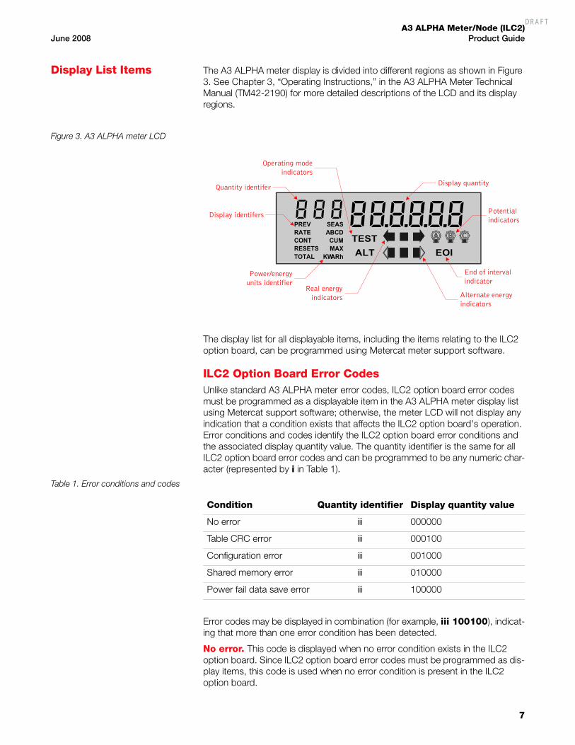
Display List Items The A3 ALPHA meter display is divided into different regions as shown in Figure 3. See Chapter 3, “Operating Instructions,” in the A3 ALPHA Meter Technical Manual (TM42-2190) for more detailed descriptions of the LCD and its display regions.
Figure 3. A3 ALPHA meter LCD
The display list for all displayable items, including the items relating to the ILC2 option board, can be programmed using Metercat meter support software.
ILC2 Option Board Error CodesUnlike standard A3 ALPHA meter error codes, ILC2 option board error codes must be programmed as a displayable item in the A3 ALPHA meter display list using Metercat support software; otherwise, the meter LCD will not display any indication that a condition exists that affects the ILC2 option board's operation. Error conditions and codes identify the ILC2 option board error conditions and the associated display quantity value. The quantity identifier is the same for all ILC2 option board error codes and can be programmed to be any numeric char-acter (represented by i in Table 1).
Table 1. Error conditions and codes
Error codes may be displayed in combination (for example, iii 100100), indicat-ing that more than one error condition has been detected.
No error. This code is displayed when no error condition exists in the ILC2 option board. Since ILC2 option board error codes must be programmed as dis-play items, this code is used when no error condition is present in the ILC2 option board.
ARh
CUM
KW
RATE
TOTALRESETSCONT
MAX
ABCDPREV SEAS
TEST
ALT EOI
Quantity identiferDisplay quantity
Potentialindicators
End of intervalindicator
Real energyindicators Alternate energy
indicators
Power/energyunits identifier
Display identifers
Operating modeindicators
Condition Quantity identifier Display quantity value
No error iii 000000
Table CRC error iii 000100
Configuration error iii 001000
Shared memory error iii 010000
Power fail data save error iii 100000
DRAFT

A3 ALPHA Meter/Node (ILC2)Product Guide June 2008
8
Table CRC error. This code indicates an error in the ILC2 option board’s pro-gramming. Contact Elster Electricity if this error code is displayed on the LCD.
General configuration error. This code indicates a problem with the ILC2 option board’s configuration or program.
■ If the node is programmed for the short data format, verify that the meter is programmed with at least one kWh quantity.
■ If the meter is programmed for load profiling, this error code will be dis-played if one of the first two quantities is programmed for a net quantity.
Contact Elster Electricity if this error code is displayed and there is no apparent programming issues.
Shared memory error. This code indicates a problem exists in the shared memory area. Contact Elster Electricity if this error code is displayed on the LCD.
Power fail data save error. This code indicates that the data saved in the ILC2 option board’s nonvolatile memory during a power failure may be invalid. This error will be displayed when power is restored to the meter if a self check has discovered an error with the ILC2 option board’s memory. Contact Elster Electricity if this error code continues to be displayed on the LCD.
ILC2 Option Board Status CodesILC2 status code must be programmed as a displayable item to appear on the A3 ALPHA meter LCD using Metercat support software. Unlike error codes, the status codes do not indicate a problem with the ILC2 option board. Status con-dition and code identifies the status condition and its associated display quantity value. The quantity identifier is the same for all ILC2 option board status codes and can be programmed to be any numeric character (represented by i in Table 2).
Table 2. Status conditions and codes
No status. This code is displayed when no status condition exists in the ILC2 option board. Since ILC2 option board error codes must be programmed as dis-play items, this code is used when no status condition is present in the ILC2 option board.
Node is registered. This code indicates that the A3 ALPHA meter with the ILC2 option board is registered with a collector. See “Network registration sta-tus” on page 9 for more specific information about the registration information.
Demand reset scheduled. This code indicates that the meter has been scheduled to perform a demand reset at the next midnight crossing. This code is displayed when the node receives a command to perform a demand reset from the network. The code remains in the display until the next midnight cross-ing (the time at which the meter performs a demand reset). See the A3 ALPHA Meter Technical Manual for more information on demand resets.
Condition Quantity identifier Display quantity value
No status iii 000000
Node is registered iii 000100
Demand reset scheduled iii 000010
DRAFT
A3 ALPHA Meter/Node (ILC2)June 2008 Product Guide
9
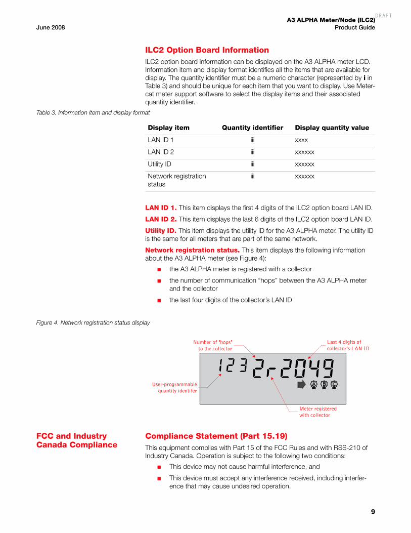
ILC2 Option Board InformationILC2 option board information can be displayed on the A3 ALPHA meter LCD. Information item and display format identifies all the items that are available for display. The quantity identifier must be a numeric character (represented by i in Table 3) and should be unique for each item that you want to display. Use Meter-cat meter support software to select the display items and their associated quantity identifier.
Table 3. Information item and display format
LAN ID 1. This item displays the first 4 digits of the ILC2 option board LAN ID.
LAN ID 2. This item displays the last 6 digits of the ILC2 option board LAN ID.
Utility ID. This item displays the utility ID for the A3 ALPHA meter. The utility ID is the same for all meters that are part of the same network.
Network registration status. This item displays the following information about the A3 ALPHA meter (see Figure 4):
■ the A3 ALPHA meter is registered with a collector
■ the number of communication “hops” between the A3 ALPHA meter and the collector
■ the last four digits of the collector’s LAN ID
Figure 4. Network registration status display
FCC and Industry Canada Compliance
Compliance Statement (Part 15.19)This equipment complies with Part 15 of the FCC Rules and with RSS-210 of Industry Canada. Operation is subject to the following two conditions:
■ This device may not cause harmful interference, and
■ This device must accept any interference received, including interfer-ence that may cause undesired operation.
Display item Quantity identifier Display quantity value
LAN ID 1 iii xxxx
LAN ID 2 iii xxxxxx
Utility ID iii xxxxxx
Network registration status
iii xxxxxx
User-programmablequantity identifer
Number of "hops"to the collector
Meter registeredwith collector
Last 4 digits ofcollector's LAN ID
DRAFT

A3 ALPHA Meter/Node (ILC2)Product Guide June 2008
10
Warning (Part 15.21)Changes or modifications not expressly approved by Elster Electricity, LLC could void the user’s authority to operate the equipment.
RF Radiation Safety Guidelines per Part 2 of FCC Rules and RegulationsThe meter should be installed in a location where there will be a separation greater than 20 cm (8 inches) from locations occupied by humans.
User Information (Part 15.105)This equipment has been tested and found to comply with the limits for a Class B digital device, pursuant to part 15 of the FCC Rules. These limits are designed to provide reasonable protection against harmful interference in a residential installation. This equipment generates, uses and can radiate radio frequency energy and, if not installed and used in accordance with the instructions, may cause harmful interference to radio communications. However, there is no guar-antee that interference will not occur in a particular installation. If this equipment does cause harmful interference to radio or television reception, the user is encouraged to try to correct the interference by one or more of the following measures:
■ Reorient or relocate the receiving antenna.
■ Move the receiving equipment farther away from the A3 ALPHA meter/collector.
■ Consult the dealer or an experienced radio/TV technician for help.
Industry Canada StatementThe term “IC” before the certification/registration number only signifies that the Industry Canada technical specifications were met.
Collocation StatementCollocation of simultaneously-transmitting (co-transmitting) antennas within 20 cm of each other in a final product is not allowed.
DRAFT

A3 ALPHA Meter/Node (ILC2)June 2008 Product Guide
11
Technical Specifications
Appendix E, “Technical Specifications,” of the A3 ALPHA Meter Technical Man-ual (TM42-2190) lists the meter specifications for an A3 ALPHA meter. When the A3 ALPHA meter is operating as a node within the EnergyAxis system, the oper-ating range for a Form 35S meter is different than the specifications listed in TM42-2190.
Operating RangesVoltage Nameplate nominal range Operating range
Form 35S 120 V to 240 V 96 V to 288 V
All other forms 120 V to 480 V 96 V to 528 V
DRAFT

A3 ALPHA Meter/Node (ILC2)Product Guide June 2008
12
DRAFT

This page is intentionally left blank.
DRAFT

Elster Electricity, LLCRaleigh, North Carolina USA+ 1 800 338 5251 (US Toll Free)+ 1 919 212 4800 (US Main)+ 1 905 634 4895 (Canada)[email protected]
This page is intentionally left blank.
DRAFT