PRELIMINARY INVESTIGATION OF FIRE AND EXPLOSION HAZARDS ...
24
NASA TECHNICAL MEMORANDUM z c NASA. TM X-53144 Ocbbr2 1964 Z PRELIMINARY INVESTIGATION OF FIRE AND EXPLOSION HAZARDS ASSOCIATED WITH S-ll INSULATION by C.. F. KEY AND J. B. GAYLE Propulsion and Vehicle Engineering Laboratory
Transcript of PRELIMINARY INVESTIGATION OF FIRE AND EXPLOSION HAZARDS ...
NASA TECHNICAL MEMORANDUM
z
c
NASA. TM X-53144
O c b b r 2 1964
Z
PRELIMINARY INVESTIGATION OF FIRE AND EXPLOSION HAZARDS ASSOCIATED WITH S-ll INSULATION
by C.. F. KEY AND J . B. GAYLE Propulsion and Vehicle Engineering Laboratory
?
TECHNICAL MEMORANDUM X-53144
PRELIMINARY INVESTIGATION OF FIRE AND EXPLOSION HAZARDS ASSOCIATED
WITH S-I1 INSULATION
C. F. Key and
J. B. Gayle
George C. Marshall Space Flight Center
Huntsville, Alabama
ABSTRACT / ' i943 - The condensation of LOX/LNz mixtures within composite insula-
tions, such as that being considered for the S-I1 vehicle, would be expected to create a fire and explosion hazard in the event of impact,
I shock, o r other stimuli.
To obtain experimental information on this problem, an investiga- tion was made in which small tanks provided with S-I1 insulation panels were filled with LH2, held for varying lengths of time, and impacted. The ' resul ts confirmed the expectation that cataetrophic failures could occur ynder these conditions but suggested that the probability of such failures ' is low and should be weighed against other factors to deter- mine if modification of the s-I1 insulation concept is necessary.
'

NASA-GEORGE C. MARSHALL SPACE FLIGHT CENTER
TECHNICAL MEMORANDUM X- 5 3 144
PRELIMINARY INVESTIGATION O F FIRE AND EXPLOSION HAZARDS ASSOCIATED
WITH S-I1 INSULATION
C. F. Key and
J. B. Gayle
CHEMISTRY BRANCH MATERIALS DIVISION ‘ i
PROPULSION AND VEHICLE ENGINEERING LABORATORY

ACKNOWLEDGEMENT
The assistance of the Applied Mechanics Research Branch, R - P & VE-PE, in providing the necessary facil- ities and personnel for transferring LHz, and conducting the tank tes ts is gratefully acknowledged. mens were fabricated by the Development Shop Section, R-P& VE-MED, and insulated by the Non-Metallic Materials Branch, R- P& VE-M.
All t es t speci-

TABLE OF CONTENTS
SUMMARY.. . . . . . . . . . . . . . . . . . . . . . . . . . . . . . . . . INTRODUCTION . . . . . . . . . . . . . . . . . . . . . . . . . . . . . . PRELIMINARY CONSIDERATION. . . . . . . . . . . . . . . . . . . EXPENMENTAL. . . . . . . . . . . . . . . . . . . . . . . . . . . . . . CONCLUSIONS . . . . . . . . . . . . . . . . . . . . . . . . . . . . . . .
LIST O F TABLES
TABLE I
Standard LOX Impact Test Results F o r S-II Ins da t ion . . . . . . . . . . . . . . . . . . . . . . . . . . . . . . . . . . .
Page 1
1
3
4
6
Page
6
i i i
LIST OF ILLUSTRATIONS
Figure
1
2
3
1 0
Title Page
0 2 / N 2 Phase Diagram . . . . . . . . . . . . . . . . . . . . 7
Calculated Temperature Profiles for S-I1 Type Insulations . . . . . . . . . . . . . . . . . . . . . . . . 8
LOX Impact Sensitivity of S-I1 Composite Insulation. . . . . . . . . . . . . . . . . . . . . . . . . . . . . 9
Test Setup for Insulated Panels . . . . . . . . . . . . . . 10
11
12
General Test Setup for Insulated Tanks . . . . . . . . .
Results fo r Insulated Tank Test No. 3 . . . . . . . . . . 1 3
Results for Insulated Tank Test No. 8 . . . . . . . . . . 1 4
Photograph of Damaged Tank After Test No. 8 . . . . . . . . . . . . . . . . . . . . . . . . . . . . . . . . 15
Photograph of Damaged Tank After Test No. 3 . . . . . . . . . . . . . . . . . . . . . . . . . . . . . . . . 16
Detailed Test Setup for Insulated Tanks. . . . . . . . .
iv

TECHNICAL MEMORANDUM X-53144
PRELIMINARY INVESTIGATION O F FIRE AND EXPLOSION HAZARDS ASSOCIATED
WITH S-I1 INSULATION
SUMMARY
The condensation of liquid oxygen/liquid nitrogen (LOX/ LNz) mixtures within composite insulations, such a s that being considered for the S-I1 vehicle, would be expected to create a f i re and explosion hazard in the event of impact, shock, o r other stimuli. The quantity of condensate and, therefore, the extent of any such hazard would be expected to be increased if the outer vapor bar r ie r of the insulation were damaged.
To obtain experimental information on this problem, an investiga- tion was made in which small tanks provided with S-I1 insulation panels were filled with LH2, held for varying lengths of time, and impacted. The resul ts confirmed the expectation that catastrophic failures could occur under these conditions but suggested that the probability of such fai lures is low and should be weighed against other factors to determine if modification of the S-I1 insulation concept is necessary.
INTRODU C TION
Many materials in contact with LOX constitute f i re and/or explosion hazards when subjected to impact, shock, heat, o r other forms of energy. Organic materials a r e especially hazardous under these conditions. Although the degree of hazard is decreased when LOX/LNz mixtures a r e substituted for LOX, evidence of sensitivity has been noted for mix- tures containing 30 percent LOX by weight. no hazard exists even with mixtures containing only 20 percent LOX (liquid a i r ) has not been obtained.
Conclusive evidence that
The selection of liquid hydrogen fo r advanced launch vehicles has necessitated the use of a wide range of new materials. In particular, the low boiling point and heat of vaporization have dictated the use of the most efficient insulations available for flight systems. External insulations currently being considered consist of reinforced rigid closed pore foams, bonded directly to the vehicle skin and covered with an essentially impermeable vapor bar r ie r . In principle, gases, primarily a i r , contained within the pores of the foam, adjacent o r close to the

foam/aluminum interface will condense o r cryopump. fa r ther away f rom the interface will cool and contract. If a leak occurs in the outer vapor ba r r i e r , cryopumping at the cold interface will continue, fed by a i r permeating the leak, until the thickness of the con- densate layer provides a sufficient thermal ba r r i e r to prevent further condensation.
Gases located
Inspection of the liquid/vapor equilibrium diagram for L O X / LN2 mixtures ( F I G 1) indicates that the concentration of oxygen in the con- densate will exceed that in the vapor phase by an amount which is dependent upon the conditions under which condensation occurs. Simi- larly, evaporation of the condensed phase during warmup of the insula- tion will cause a further increase in the concentration of oxygen in the condensate residue remaining at any time after evaporation begins. Since both the quantity of condensate and the concentration of oxygen in the condensate depend on the size of the leak, the permeability of the foam, and other poorly defined variables, i t appears evident that condi- tions could be established under which a significant quantity of conden- sate containing appreciably more than 20 percent oxygen would accumu- late within the foam portion of the insulation. materials used for this application a r e known to be susceptible to im- pact i n L O X / L N 2 mixtures containing more than 20 percent LOX, an investigation was initiated to study the hazards associated with conden- sate formed within damaged insulation on LH2 containers. Since the development of an acceptable insulation was considered a schedule pacing i tem for the S-I1 stage of the Saturn V vehicle, this study was restr ic ted to the particular insulation concept under consideration for that stage.
Because the foam
2

PRELIMINARY CONSIDERATION
Figure 2 gives computed steady state temperature profiles f o r LHz containers covered with 0.8 and 1.6 inches of the proposed S-II composite insulation. This insulation consists of polyurethane foam bonded to the aluminum tank surface with an epoxy-type adhesive. Phenolic fiberglass honeycomb is pressed into the foam for reinforce- ment,and the o m surface is covered with an essentially impermeable vapor ba r r ie r.
The approximate boiling point temperature for liquid a i r is indi- cated in FIG 2 with the distances from the foam/aluminum interfaces at which this temperature occurs. condensate layers (combined solid and liquid) a r e 0.15 and 0. 30 inch, respectively, for the 0.8finch and 1. 6-inch insulations. Assuming a density of 1.1 gm/cm3, the corresponding weights of condensate a r e in excess of 300 and 600 gm/ft2, respectively. greatly exceed the weights of a i r present initially within the composite insulations, they can be realized only if the vapor b a r r i e r is inherently permeable, if it contains leaks, or i f accumulation of condensate occurs at a specific location within intact insulation. typical vqpor ba r r i e r materials was determined to be of the order of
corresponding rate of a i r permeation per square foot per hour is negligible for this application. The permeability of the polyurethane . foam also is relatively low. comb reinforcement is applied creates numerous gross leakage paths extending f rom the surface of the foam to the foam/aluminum interface. Thus, the requirement that a relatively good vacuum be attained within the insulation is solely dependent on the integrity of the vapor barr ier .
The indicated thicknesses of the
Sincf these weights
The permeability of
S. P. Ua * F o r a pressure differential of one atmosphere, the
However, the manner in which the honey-
Consideration of the large areas and complex shapes of the sur - faces which must be insulated suggests that leaks in the vapor ba r r i e r a r e extremely probable. either the thickness or the oxygen concentration of condenSate layers in damaged insulations and also because of the uncertainties attendant to the initiation of reactions between composite materials and LOX/LNz
Because of the difficulties in predicting
*One permeability unit ( S P U ) is defined as the number of cubic centimeters of a gas at STP (OOC, 1 atma) passing through one square centimeter of material, one centimeter thick, under a pressure grad- ient of one centimeter Hg (10 t o r r ) , in one second. 'Thus, the equivalent units for 1 SPU= 1 cm3 (STP).r'cm-2. (cm Hg)-l sec-1.
3

mixtures, a direct, but limited, experimental investigation of the problem was carr ied out.
EXPERIMENTAL
Standard LOX impact tes ts were made on samples of the composite insulation and on each of the constituent materials. in Table I indicate that the insulation and i ts constituents a r e highly sensitive to impact in LOX. Because the condensate formed within a damaged insulation would be expected to have an oxygen concentration intermediate between that of liquid a i r and LOX, the tes ts on the com- posite insulation were repeated using LOX/LN2 mixtures. xc
given in F I G 3 indicate a marked decrease in sensitivity with decreas- ing LOX concentration; samples tested in 20/80 LOX/LNz weight mixtures met the standard acceptance cri terion of no reactions in 20 tests at 10 kilogram meters.
The results given
The results
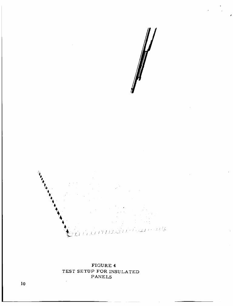
To obtain a more realist ic test configuration, additional tes ts were made by using flat aluminum test panels, each covered with a 1/2-inch thickness of composite insulation with the vapor ba r r i e r either removed o r perforated to insure permeation of LOX into the insulation core. These panels, shown in FIG 4, were immersed in LOX/LN2 mixtures for approximately 15 minutes, removed, and allowed to stand for varying lengths of time before being impacted by approximately 125 #12 lead shot f i red from a . 22 calibre rifle. hk* The results of these tes ts indi- cated that reactions occurred consistently when the gun was located l e s s than about 50 inches f rom the target if the concentration of LOX in the LOX/LN2 mixture exceeded some threshold value, roughly 20 percent. I t was noted that the frequency of reactions appeared to increase with increasing hold time (up to approximately 5 minutes) for tes ts with LOX/LNz mixtures containing 20 to 30 percent LOX. This i s consistent
*All LOX/LN2 mixtures used f o r this investigation were prepared by weighing the desired quantity of LOX and then adding the necessary quantity of LN2 to give the desired total weight of mixture,
**Each shot weighed approximately 0. 013 gm. Average shot veloo- i ty measured between 1 and 3 feet f rom the gun muzzle was approxi- mately 900 fps. were not impact sensitive in LOX at 10 kilogram meters.
Standard impact tes ts indicated that the lead shots
with the expected increase in concentration of LOX in the liquid residue during warmup of the tes t specimen. Siranjlar resuJts were obtained i n tes ts using .177 calibre copper-coated pellets f i red f rom an air rifle. flat panels) immersed in LOX/LN2 mixtures after damaging the insu- lation by perforating the vapor bar r ie r over each cell or by making saw cuts test section of the tank insulation. These cuts were approximately 1 /2 inch deep and extended to the adhesive bond adjacent to the metal tank wall.
Similar results also were obtained using test tanks (instead of
1/16 inch wide and approximately 4 inches long across the
The tests discussed above were made with LOX/LN2 mixtures being introduced in the tes t specimen by direct immersion beforehandL To obtain a much more realistic simulation, tests were run in which insulated tanks were filled with LH2 and held for varying lengths of time before impacting to allow natural cryopumping. is shown schematically in FIG 5. Test tanks were constructed and insulated a s shown in FIG 6. After the tes t tanks were filled with LH2, the samples were impacted with bird shot, f i red remotely f rom a . 22 calibre rifle located 18 to 27 inches f rom the tank surface, The results we r e r e cor de d photographic ally.
The tes t system
For the initial tests, the outer vapor b a r r i e r was punctured so that air would be liquefied in the sample cells. four horizontal slots were cut in the sample to the tank skin to simula- damaged o r defective insulation.
For the latter tests,
Instrumentation for all tests, except the third, included two copper- constantan thermocouples. with the tank skin, and the other was placed in the sample core. the third test, two thermocouples were placed in each of the above mentioned areas. The liquid hydrogen level in the tank was monitored with carbon resistors. Additionally, the tank pressure was monitored as a safety precaution.
One thermocouple was placed in contact F o r
Each tank was filled with liquid hydrogen and maintained full f o r periods varying f rom 4 to 12 hours, depending on ambient conditions, sample temperature, and the degree of liquid a i r saturation of the in- sulation sample. For each impact, the LH2 supply was shut-off; then, the sample was impacted one o r more times.
5
L
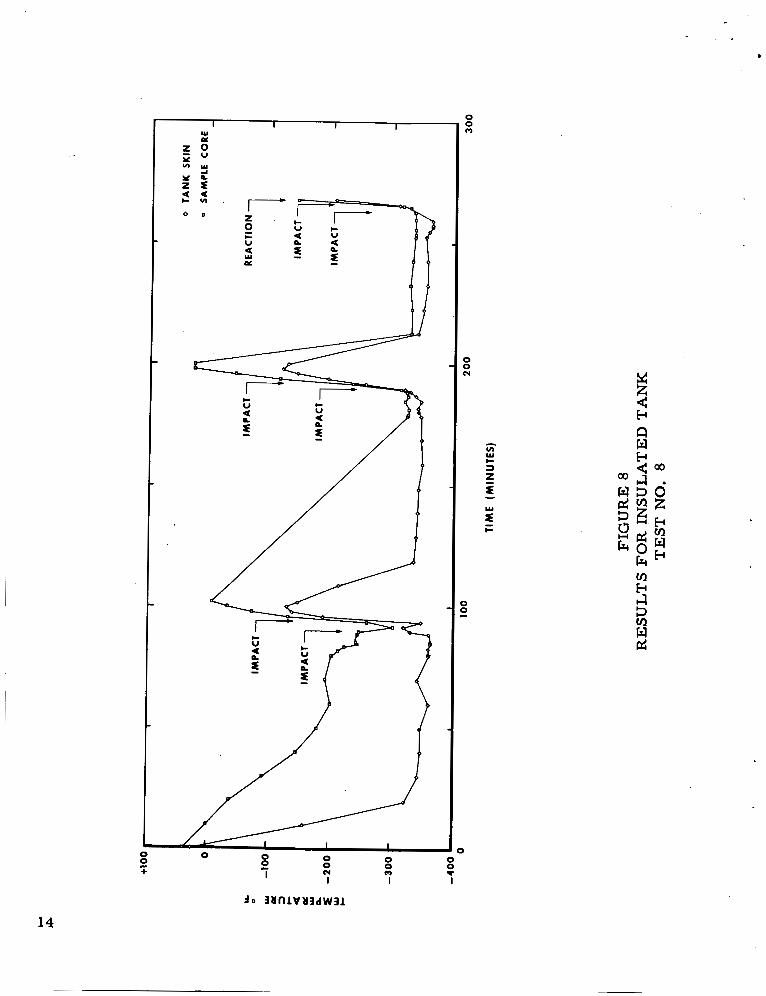
F o r the 9 tanks tested, 57 impacts were made. During the tests, liquid a i r wetting of most of the samples was observed. impacts were directed at the wetted portions of the samples. burning occurred 10 minutes and 8 minutes following shut-off of LH2 supply in Runs No. 3 and 8, respectively. for these runs a r e presented in F IG 7 and 8. tanks a r e shown in FIG 9 and 10. was much more violent than the reaction after 8 minutes warmup, which suggested either a la rger quantity of condensate o r a larger per- centage of oxygen in the condensate.
Generally, Sustained
Temperature time curves Photographs of the burned
The reaction after 10 minutes warmup
CONCLUSIONS
There i s a small but finite probability of occurrence of a catastro- phic reaction if damaged S-I1 insulation i s subjected to impact, shock, fire, o r other stimuli during o r subsequent to LHz hold. probably i s greatest during warmup of the insulation after testing o r detanking operations. other factors such as reliability, time, weight, cost, etc., to deter- mine whether a purge o r other modification i s required.
The hazard
This small hazard must be considered with
TABLE I
STANDARD LOX IMPACT TEST RESULTS FOR S-I1 INSULATION
Mate rial Frequency of Reactions at 10 kgm, percent
C o mp o s i t e Ins ul at i o n 1 0 0 . 0
Ht 424 100 .0
Hexcell 91 LD 100.0
Polyurethane Foam 7.'5
6

\
I -
9 2
90
88
86
84
82
8 0
78
76
7 4
7 2
7 0 0
I I I I I I I I I
2 0 40 60 8 0
OXYGEN IN MIXTURE, MOLE PERCENT
FIGURE 1
02JN2 PHASE DIAGRAM
100
7

5 5 0
500
450
400
3 5 0
300
250
200
150
100
sa
a 0 2 0.20 0.40 0.60 0.80 1.00 1.20 1.40 1.60
INSULATION THICKNESS (INCHES)
FIGURE 2
TYPE INSULATIONS CALCULATED TEMPERATURE PROFILES FOR S-I1
8
I

0 0 OD I!
0 0
z W
w
9
4
F I G U R E 4 T E S T S E T U P FOR INSULATED
P A N E L S
10

Y c P t
c
4 30 psi Y I
f
- 1 U a
I >
F I G U R E 5 GENERAL TEST SETUP FOR INSULATED
TANKS
11

FIGURE 6 DETAILED TEST S E T U P FOR INSULATED
TANKS
12

I-- z
a
I_
o o o *
4 1
J o 3UlllVU3dW31
a
FIGURE 7 RESULTS FOR INSULATED TANK TEST
NO. 3
13
0
+ 2 0 0 0 0 0 (Y 0
0
7 I I
d
14

FIGURE 9 PHOTOGRAPH O F DAMAGED TANK AFTER TEST
NO. 8

FIGURE 10 PHOTOGRAPH O F DAMAGED TANK A F T E R TEST NO. 3
16

October 2, 1964 APPROVAL TMX- 5 3 144
PRELIMINARY INVESTIGATION O F FIRE AND EXPLOSION HAZARDS ASSOCIATED
WITH S-II. INSULATION
By C. F. Kev and J. B. Gayle
The information i n this report has been reviewed fo r security classification. Review of any information concerning Department of Defense o r Atomic Energy Commission programs has been made by the MSFC Security Classification Officer. This report, i n its entirety, has been determined to be unclassified.
This document has also been reviewed and approved for technical rccuracy.
- W. RIEHL Chief, Chemistry Branch
Chief, Materials Division
‘r’Director, Propulsion and Vehicle Engineering Laboratory

DISTRIBUTION
DIR Dr. yon Braun DEP-T Dr. Rees R-DIR Mr. Weidner K-DIR Dr. Debus E?& 6 Mr. Body v Dr. Gruene R-AERO-DIR Dr. Geissler I-I/IB -mR col. L. James R-P&VE-DIR Mr. Cline R-P&VE-M Dr. Lucas ( 5 ) R -P & VE -M C Mr. Riehl ( 5 5 ) R-P& VE-ME Mr. Kingsbury REP&VE-MM Mr. Cataldo R- P & VE -MN Mr. Shannon R-l?&VE-P Mr. Paul R- P & VE -PE Mr. Head R-P&VE-PM Mr. Voss R-P&VE-S Mr. Kroll R-P&VE-V Mr. Aberg R-P&VEXL Mr. Faulkner R-P & VE - VO Mr. Kistler R-P&VE-VSA Mr. Prasthofer R-TEST-DIR Mr. Heimburg R-TEST-M Mr. Dyer R-@EST-T Mr. Driscoll MS-F Mr. Roberts R-P&VE-RT Mr. Hofues MS-H Mr. Akens MS-IP Mr. Remer MS -1PL Miss Robertson ( 8 ) cc-P Mr. W off o r d MS-T M r . W iggins
Scientific and Technical Information Facility Attn: NASA Repre& entative (S-AK/RKT) P. 0. Box5700 Bethesda, Maryland 20014
(25)