
Preface, Contents 1 SIMATIC 2 3 Safety Matrix 4 5 6 7 8 9 ... manual is valid for the software...
96
s Preface, Contents Introduction to Safety Matrix 1 Guidelines for Safety Critical Functions 2 Getting Started 3 Configuration 4 Operation 5 Safety Matrix Menu Options 6 Importing a Safety Matrix 7 Safety Matrix Viewer 8 Safety Matrix Editor 9 Logic Detail Diagrams 10 Migrating Matrices from QUADLOG ® to S7F 11 Glossary 12 Index SIMATIC Safety Matrix User's Guide Edition 05/2004 A5E00265325-01
Transcript of Preface, Contents 1 SIMATIC 2 3 Safety Matrix 4 5 6 7 8 9 ... manual is valid for the software...

s
Preface, Contents
Introduction to Safety Matrix 1 Guidelines for Safety Critical Functions 2 Getting Started 3 Configuration 4 Operation 5 Safety Matrix Menu Options 6 Importing a Safety Matrix 7 Safety Matrix Viewer 8 Safety Matrix Editor 9 Logic Detail Diagrams 10 Migrating Matrices from QUADLOG® to S7F
11
Glossary 12 Index
SIMATIC
Safety Matrix User's Guide
Edition 05/2004 A5E00265325-01

Copyright © Siemens AG 2004 All rights reserved
The reproduction, transmission or use of this document or its contents is not permitted without express written authority. Offenders will be liable for damages. All rights, including rights created by patent grant or registration of a utility model or design, are reserved. Siemens AG Bereich Automation and Drives Geschaeftsgebiet Industrial Automation Systems Postfach 4848, D- 90327 Nuernberg
Disclaimer of Liability
We have checked the contents of this manual for agreement with the hardware and software described. Since deviations cannot be precluded entirely, we cannot guarantee full agreement. However, the data in this manual are reviewed regularly and any necessary corrections included in subsequent editions. Suggestions for improvement are welcomed. ©Siemens AG 2004 Technical data subject to change.
Siemens Aktiengesellschaft A5E00265325-01
Safety Guidelines
This manual contains notices that you should observe to ensure your own personal safety, as well as to
protect the product and connected equipment against damage. These notices are highlighted in the
manual by a warning triangle and are marked as follows according to the level of danger:
! Safety Note Contains important information relating to approval and safety-related use of a product.
! Danger Indicates that death, severe physical injury, or substantial property damage will result if proper precautions are not taken.
! Warning Indicates that death, severe physical injury, or substantial property damage can result if proper precautions are not taken.
! Caution Indicates that minorphysical injury or property damage can result if proper precautions are not taken.
Caution
Indicates that property damage can result if proper precautions are not taken.
Note
Indicates important information relating to the product, or draws special attention to part of the documentation.
Qualified Personnel
This device/system may only be set up and operated by qualified personnel. Qualified personnel are
defined as persons who are authorized to commission, to ground, and to tag circuits, equipment, and
systems in accordance with established safety practices and standards.
Proper Use
Note the following:
! Warning This device and its components may only be used for the applications described in the catalog or the
technical description, and only in connection with devices or components from other manufacturers
which have been approved or recommended by Siemens.
This product can only function correctly and safely if it is transported, stored, set up, and installed correctly, and operated and maintained as recommended.
Trademarks
SIMATIC®, SIMATIC HMI® and SIMATIC NET® are registered trademarks of SIEMENS AG.
Third parties using for their own purposes any other names in this document which refer to trademarks
might infringe upon the rights of the trademark owners.
Safety Matrix User's Guide A5E00265325-01 iii
Preface
Purpose of the Manual
This manual provides a complete overview of the Safety Matrix application.
This manual is intended for the programmers of Safety Matrix programs and for those responsible for configuring, commissioning, and servicing automation systems.
Required Basic Knowledge
You require a general knowledge of the field of automation engineering to be able to understand this manual.
In addition, you should know how to use computers or devices with similar functions (e.g programming devices) under Windows operating systems.
Where is this Manual valid?
This manual is valid for the software package SIMATIC Safety Matrix V5.2.
Standards, Certificates and Approvals
The Safety Matrix is certified for use in safety mode up to the following levels:
• Requirement classes AK1 to AK6 in accordance with DIN V 19250/DIN V VDE
• SIL1 to SIL3 (Safety Integrity Level) in accordance with IEC 61508
• Categories 1 to 4 in accordance with EN 954-1

Preface
Safety Matrix User's Guide iv A5E00265325-01
Further Support
If you have any technical questions, please get in touch with your Siemens representative or agent responsible.
You will find your contact person at:
http://www.siemens.com/automation/partner
You will find a guide to the technical documentation offered for the individual SIMATIC Products and Systems here at:
http://www.siemens.com/simatic-tech-doku-portal
The online catalog and order system is found under:
http://www.mall.ad.siemens.com/
Training Centers Siemens offers a number of training courses to familiarize you with the SIMATIC S7 automation system. Please contact your regional training center or our central training center in D 90327 Nuremberg, Germany for details:
Telephone: +49 (911) 895-3200.
Internet: http://www.sitrain.com

Preface
Safety Matrix User's Guide A5E00265325-01 v
A&D Technical Support Worldwide, available 24 hours a day:
Beijing Peking
Nuernberg
Johnson City
Worldwide (Nuernberg)
Technical Support
24 hours a day, 365 days a year
Phone: +49 (180) 5050-222
Fax: +49 (180) 5050-223
mailto:[email protected]
GMT: +1:00
Europe / Africa (Nuernberg)
Authorization
Local time: Mon.-Fri. 8:00 to 5:00 PM
Phone: +49 (180) 5050-222
Fax: +49 (180) 5050-223
mailto:[email protected]
GMT: +1:00
United States (Johnson City)
Technical Support and Authorization
Local time: Mon.-Fri. 8:00 to 5:00 PM
Phone: +1 (423) 262 2522
Fax: +1 (423) 262 2289
mailto:[email protected]
GMT: -5:00
Asia / Australia (Beijing)
Technical Support and Authorization
Local time: Mon.-Fri. 8:00 to 5:00 PM
Phone: +86 10 64 75 75 75
Fax: +86 10 64 74 74 74
mailto:[email protected]
GMT: +8:00
The languages of the SIMATIC Hotlines and the authorization hotline are generally German and English.

Preface
Safety Matrix User's Guide vi A5E00265325-01
Service & Support on the Internet In addition to our documentation, we offer online support on the internet at:
http://www.siemens.com/automation/service&support
where you will find the following:
• The newsletter, which constantly provides you with up-to-date information on your products.
• The right documents via our Search function in Service & Support.
• A forum, where users and experts from all over the world exchange their experiences.
• Your local representative for Automation & Drives via our representatives database.
• Information on field service, repairs, spare parts and more under "Services".

Safety Matrix User's Guide A5E00265325-01 vii
Table of Contents 1 Introduction to Safety Matrix 1-1
1.1 Cause and Effect Matrix Methodology............................................................1-1 1.2 Safety Matrix Overview..................................................................................1-2 1.2.1 Defining the matrix – brief overview .............................................................. 1-3 1.3 Mode of Operation.........................................................................................1-4 1.4 Product Overview ..........................................................................................1-5
2 Guidelines for Safety Critical Functions 2-1
3 Getting Started 3-1
3.1 Hardware Requirements ................................................................................3-1 3.2 Software Requirements .................................................................................3-1 3.3 Installation .....................................................................................................3-2
4 Configuration 4-1
4.1 Creating a New Safety Matrix ........................................................................4-1 4.2 Configuring the Safety Matrix Logic................................................................4-3 4.3 Adding and Editing Causes............................................................................4-4 4.3.1 Adding a cause............................................................................................. 4-4 4.3.2 Editing a cause............................................................................................. 4-4 4.4 Cause - Configure Tab ..................................................................................4-5 4.5 Cause - Analog Parameters Tab....................................................................4-9 4.6 Cause - Options Tab....................................................................................4-11 4.7 Adding and Editing Effects...........................................................................4-14 4.7.1 Adding an effect ......................................................................................... 4-14 4.7.2 Editing an effect.......................................................................................... 4-15 4.8 Effect - Configure Tab..................................................................................4-16 4.9 Effect - Options Tab.....................................................................................4-18 4.10 Adding and Editing Intersections..................................................................4-23 4.11 Intersection Type Dialog Box .......................................................................4-24 4.12 Editing General Information .........................................................................4-26 4.13 Matrix Project Utilities ..................................................................................4-28
5 Operation 5-1
5.1 Viewing a Safety Matrix in Monitor Mode .......................................................5-1 5.2 Color Status Indicators ..................................................................................5-2 5.3 Controlling the System in Monitor Mode.........................................................5-3 5.4 Entering Maintenance Changes in Monitor Mode .........................................5-11 5.5 Making Changes In Monitor Mode ...............................................................5-13 5.6 Exiting Monitor Mode ...................................................................................5-14
6 Safety Matrix Menu Options 6-1
6.1 File Menu ......................................................................................................6-2 6.2 Edit Menu ......................................................................................................6-3 6.3 View Menu ....................................................................................................6-4 6.4 Tools Menu ...................................................................................................6-7 6.5 Window Menu................................................................................................6-9 6.6 Help Menu...................................................................................................6-10
Table of Contents
Safety Matrix User's Guide viii A5E00265325-01
7 Importing a Matrix File 7-1
8 Safety Matrix Viewer 8-1
8.1 Safety Matrix Viewer Prerequisites ................................................................8-1 8.2 Configuring the Safety Matrix Viewer .............................................................8-5 8.3 Operating the Safety Matrix Viewer................................................................8-7 8.4 Safety Matrix Viewer Security Considerations ..............................................8-10
9 Safety Matrix Editor 9-1
10 Logic Detail Diagrams 10-1
11 Migrating a Matrix from QUADLOG to S7 F Systems 11-1
12 Glossary 12-1

Safety Matrix User's Guide A5E00265325-01 1-1
1 Introduction to Safety Matrix
The Safety Matrix is a toolkit that reduces configuration, testing and maintenance time by merging the traditionally separate steps of creating a cause and effect matrix diagram, and configuring the safety system. It was developed as both a tool and a methodology.
1.1 Cause and Effect Matrix Methodology
Cause and effect matrix methodology is used for defining how and when actions are executed in a safety system. This methodology involves organizing process events into categories of causes and effects, and then linking these causes and effects. The links between the causes and effects are called intersections, which indicate the effects that will result from an active cause. From this data, logic can be extracted to create a program for executing a system of responses to contain and prevent events before they cause damage to a process.
Introduction to Safety Matrix
Safety Matrix User's Guide 1-2 A5E00265325-01
1.2 Safety Matrix Overview
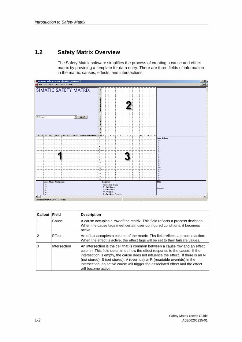
The Safety Matrix software simplifies the process of creating a cause and effect matrix by providing a template for data entry. There are three fields of information in the matrix: causes, effects, and intersections.
Callout Field Description
1 Cause A cause occupies a row of the matrix. This field reflects a process deviation. When the cause tags meet certain user-configured conditions, it becomes active.
2 Effect An effect occupies a column of the matrix. Ths field reflects a process action. When the effect is active, the effect tags will be set to their failsafe values.
3 Intersection An intersection is the cell that is common between a cause row and an effect column. This field determines how the effect responds to the cause. If the intersection is empty, the cause does not influence the effect. If there is an N (not stored), S (set stored), V (override) or R (resetable override) in the intersection, an active cause will trigger the associated effect and the effect will become active.
Introduction to Safety Matrix
Safety Matrix User's Guide A5E00265325-01 1-3
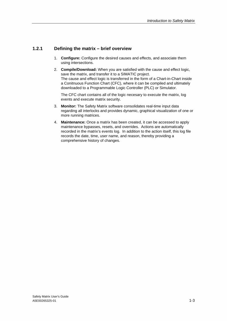
1.2.1 Defining the matrix – brief overview
1. Configure: Configure the desired causes and effects, and associate them using intersections.
2. Compile/Download: When you are satisfied with the cause and effect logic, save the matrix, and transfer it to a SIMATIC project. The cause and effect logic is transferred in the form of a Chart-in-Chart inside a Conitnuous Function Chart (CFC), where it can be compiled and ultimately downloaded to a Programmable Logic Controller (PLC) or Simulator.
The CFC chart contains all of the logic necesary to execute the matrix, log events and execute matrix security.
3. Monitor: The Safety Matrix software consolidates real-time input data regarding all interlocks and provides dynamic, graphical visualization of one or more running matrices.
4. Maintenance: Once a matrix has been created, it can be accessed to apply maintenance bypasses, resets, and overrides. Actions are automatically recorded in the matrix’s events log. In addition to the action itself, this log file records the date, time, user name, and reason, thereby providing a comprehensive history of changes.

Introduction to Safety Matrix
Safety Matrix User's Guide 1-4 A5E00265325-01
1.3 Mode of Operation
The Safety Matrix Programming Tool can be used in two different modes of operation, including:
• Offline Mode Develop a cause and effect matrix that defines a safety function. Offline mode also supports project compilation and download capabilites.
• Monitor Mode View real-time values and monitor the status of the matrix.
It is recommended that you create a matrix in the offline mode, and test it in the monitor mode using the PLC Simulator before downloading it to your system.
Note
Retain a copy of each matrix before editing so that you have a record of all your changes.

Introduction to Safety Matrix
Safety Matrix User's Guide A5E00265325-01 1-5
1.4 Product Overview
The SIMATIC Safety Matrix product line consists of three major components:
• Safety Matrix Engineering Tool
• Safety Matrix Viewer
• Safety Matrix Editor
These components support different roles in the design and operation of cause and effect logic.
Safety Matrix Engineering Tool Provides the complete suite of tools to create, configure, compile, and
download matrices in the SIMATIC STEP 7 Engineering Station (ES) environment. It additionally supports communication with a run-time Programmable Logic Controller (PLC) to allow testing of the matrix logic.
Safety Matrix Viewer Supports matrices in the PCS 7 Operating Station (OS) of a PCS 7 WinCC environment. The Safety Matrix Viewer displays the run-time matrix logic in the PLC in a format consistent with that of the Safety Matrix Engineering Tool. Multiple levels of operator matrix functionality are protected by OS user rights.
Safety Matrix Editor Provides the remote workstation the ability to create and review matrix logic without the need for SIMATIC STEP 7 or the PCS 7 environments. Matrices developed or modified on the Safety Matrix Editor can be conveniently emailed, or otherwise shared with a Safety Matrix Engineering Tool user for incorporation into a SIMATIC project.
SafetyMatrixEditor
Remote User Workstation
Shared Matrix File(* .CEM)
Safety MatrixViewer
Operator Station (OS)
Safety MatrixEngineering
Tool
Engineering Station (ES)
Controller (AS)

Introduction to Safety Matrix
Safety Matrix User's Guide 1-6 A5E00265325-01

Safety Matrix User's Guide A5E00265325-01 2-1
2 Guidelines for Safety Critical Functions
The following guidelines shall apply when the Safety Matrix Option Package is used for safety critical functions:
1. The Safety Matrix is an Option Package of S7 F/FH Systems. The user should read, understand, and comply with all Safety Notes in the "SIMATIC Programmable Controllers S7 F/FH Systems Manual".
2. The safety certification is only valid for Safety Matrix version 5.2.0.0 and higher.
3. Refer to the "Matrix Project Utilities" procedures in this document for validation and verification of the matrix logic.
4. The PLCSim cannot be used for final validation and verification of the Safety Matrix logic. Use the PLCSim as a means of checking and debugging the logic prior to download to a controller. Validation and verification of the Safety Matrix logic can only be done on an actual system.
5. The I/O Modules generate data quality information. This quality information can be read and used by the Safety Matrix logic. The quality information is associated with the data as it is read, not passed through with the logic result. The user can configure cause options to trip on bad quality if a response to bad quality is required.
6. The Safety Matrix monitor mode is not a safety critical component and is not to be used as part of the safety function. All safety function responses shall be part of the controller logic.
7. The input and output channel configuration should be consistent with the Energize-to-trip (trip on true) or De-energize-to-trip (trip on false) sense of the Safety Matrix cause and effect configuration. De-energize-to-trip is the default logic sense.
8. Online monitor command changes must be verified by inspecting the readback values.
9. Refer to section 4.1.3 of the TÜV Certifcate for the Fail-safe Components of the S7 F/FH Systems for further guidelines with online changes. (refer to the TÜV website: <www.tuv-fs.com>)
10. The current versions of the following functional safety certification documents should be reviewed prior to using the Safety Matrix for safety critical applications:
- TÜV Certifcate for the Fail-safe Components of the S7 F/FH Systems
- Annex 1 of TÜV Certifcate for the Fail-safe Components of the S7 F/FH Systems
- Annex 3 of TÜV Certifcate for the Fail-safe Components of the S7 F/FH Systems

Guidelines for Safety Critical Functions
Safety Matrix User's Guide 2-2 A5E00265325-01
11. The following operations must adhere to the TÜV “Maintenance Override“ guidelines:
- Online forcing
- Parameter changes
- Maintenance overrides
These operations are the sole responsibility of the operator.
The TÜV certificate does not allow output overrides.

Safety Matrix User's Guide A5E00265325-01 3-1
3 Getting Started
3.1 Hardware Requirements
The basic hardware requirements for running the Safety Matrix software include:
• PC with a CD-ROM drive
• F-System hardware components:
- S7 F/FH System CPUs (e.g. the CPU 417-4 H) with an F-Copy License
- Fail-safe Signal Modules (F-SM)
3.2 Software Requirements
The following software is required to operate the Safety Matrix components at their full capacity:
Common Requirements • Internet Explorer V6.0, SP1 or greater
Safety Matrix Engineering Tool • S7 F-Systems V5.2 or greater
• S7 F Lib V1.2 or greater
• STEP 7 V5.2 or greater
• CFC V6.0 or greater
• Windows 2000 Professional SP3 or greater, or Windows XP Professional
Safety Matrix Viewer • PCS 7 OS V6.0 SP2 or greater
• Windows 2000 Professional SP3 or greater
Safety Matrix Editor • Windows 2000 Professional SP3 or greater, or Windows XP Professional

Getting Started
Safety Matrix User's Guide 3-2 A5E00265325-01
3.3 Installation
The SIMATIC Safety Matrix for S7 F-System components is installed from the Safety Matrix Installation CD, as follows:
1. Place the Safety Matrix Installation CD into the CD-ROM drive of your PC.
2. From the Windows Start menu, select Run and type E:\setup.exe (replace E for your designated CD ROM drive if different) in the RUN dialog box. Click OK. You can also initiate the setup program by double-clicking your CD-ROM drive icon in the My Computer dialog box, and selecting the setup icon from the program folder.
3. Follow the setup program instructions to select the desired Safety Matrix components.
4. Install appropriate runtime licenses for the Safety Matrix Engineering Tool, Safety Matrix Viewer, and Safety Matrix Editor.
Note
Multiple language support is limited to the help file and user guide. Language selection is based on STEP 7 language (if installed), or Windows language setup.

Safety Matrix User's Guide A5E00265325-01 4-1
4 Configuration
4.1 Creating a New Safety Matrix
In a SIMATIC project, the cause and effect logic resides in a Matrix object, where the logic is configured and transferred in the form of a function block inserted on a CFC chart. Each Matrix object supports up to 128 causes and 128 effects, with a maximum of 500 intersections. A controller can support multiple matrices up to the memory capacity of the controller.
Adding a Matrix object to a project 1. Open the project in SIMATIC Manager.
2. Navigate to the S7 Program folder within the project.
3. Right-click the S7 Program folder, and select Insert New Object>Matrix Folder. A matrix folder will be added to the S7 Program.
Configuration
Safety Matrix User's Guide 4-2 A5E00265325-01
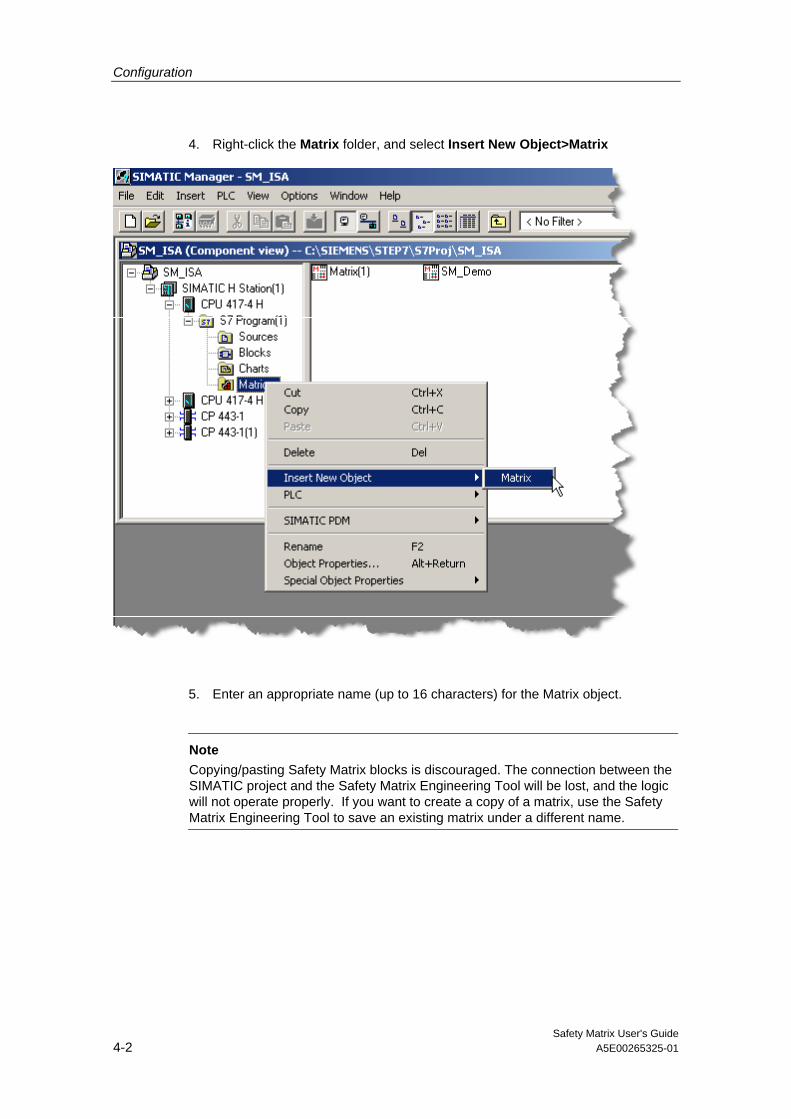
4. Right-click the Matrix folder, and select Insert New Object>Matrix
5. Enter an appropriate name (up to 16 characters) for the Matrix object.
Note Copying/pasting Safety Matrix blocks is discouraged. The connection between the SIMATIC project and the Safety Matrix Engineering Tool will be lost, and the logic will not operate properly. If you want to create a copy of a matrix, use the Safety Matrix Engineering Tool to save an existing matrix under a different name.

Configuration
Safety Matrix User's Guide A5E00265325-01 4-3
4.2 Configuring the Safety Matrix Logic
Configuring a new Safety Matrix Double-click the Matrix object in SIMATIC Manager. The Safety Matrix Engineering Tool will open as shown below.

Configuration
Safety Matrix User's Guide 4-4 A5E00265325-01
4.3 Adding and Editing Causes
4.3.1 Adding a cause
1. Double-click anywhere in the cause section of a blank row. If there are no blank rows in the matrix, you can add a row by increasing the size of the matrix.
2. To increase the size of the matrix, select View>Options. The Matrix Options dialog box will be displayed.
3. Type the desired value in the Number of Causes edit box. The matrix is selectable between 16-128.
Note
By right-clicking inside an existing row of a cause, the Insert Row command will add a blank cause to a matrix. However, if there are no blank rows in the matrix, inserting a blank row will cause the last row in the matrix to be shifted out (deleted). Use the Matrix Options dialog box to increase the size of a matrix before using the Insert Row command.
4.3.2 Editing a cause
Double-click on any cell in the cause section of a row. The Configuration for Cause # dialog box will be displayed. This dialog box can also be accessed by right-clicking a cause, and selecting Edit Cause from the pop-up menu.

Configuration
Safety Matrix User's Guide A5E00265325-01 4-5
4.4 Cause - Configure Tab
Field Description
Cause Number This is a unique number assigned to each cause. This number is assigned automatically based on the row selected. The cause number cannot be changed from this dialog box.
Desc (Description) This is an alpha/numeric description of the cause. The description is a required field, and can be up to 32 characters in length.

Configuration
Safety Matrix User's Guide 4-6 A5E00265325-01
Field Description
Tag # These are the symbol names of the inputs configured in the SIMATIC project available for the selected Input Type. The types of cause tags allowed include I/O and internal variable. • Analog and/or Discrete input tags – Selecting the I/O button will open the
Select I/O Tag dialog box. The Select I/O Tag dialog box provides a list of symbols available as input tags.
• External inputs - Identified by a prefix "#" character, external inputs will cause an input nub to be created on the matrix CFC chart for connection to user logic.
This is a required field. Note: The Safety Matrix Engineering Tool Tag automatically places tag channel drivers during the transfer process into a CFC chart. To connect the channel driver to additional logic outside the matrix, append a "#" character to the configured tag. The Safety Matrix Engineering Tool will route the channel driver to an output of the CFC chart. You can connect to this output as if it were the channel driver. If the tag has already been configured by another matrix or user logic, the transferred matrix will connect to the existing channel driver. Connection to an existing channel driver will be identified by the Safety Matrix Engineering Tool with the "@" prefix in the tag’s configuration field.
Energize-To-Trip Inputs (Trip on True)
This option is for Discrete input types and determines which Boolean state represents an unsafe (trip) condition. In De-energize-To-Trip applications, the cause tag represents an unsafe (trip) condition when it turns OFF (becomes FALSE). In De-energize-To-Trip applications, the cause tag represents an unsafe (trip) condition when it turns ON (becomes TRUE). This check box is not selected (De-energize-To-Trip) in the default setting.

Configuration
Safety Matrix User's Guide A5E00265325-01 4-7
Field Description
Safety Integrity Level (SIL)
A SIL value is a ranking of the severity of a hazardous event and the likelihood of it occurring. The higher the SIL value, such as a SIL of 3, the more severe the hazardous event and the likelihood of it occurring. A SIL of 1 indicates less severity and likelihood of occurrence. SIL level is calculated for an entire Safety Integrated Function (SIF). This field is used to document the desired SIL level for this cause. You must ensure field devices and cause configuration meet the requirements of the intended SIL level. Methods for determining SILs are varied. The table below illustrates how a SIL can be determined by comparing the severity of a hazardous event to the frequency of its occurrence. Two sources for methods in assigning a SIL are the standards ISA S84 and IEC 61508. Entering a SIL value in the matrix is optional as it is used for documentation purposes only. In the default setting, a SIL value is not entered.
Severe
Serious
Minor
HazardousEvent
Security
1 1
1
2
2
2
3
33
Improbable Occasional Frequent
Unmitigated Event Frequency
Input Type An input type must be selected for each cause.
• Discrete The discrete type is a Boolean value (TRUE/FALSE). For example, it is used
with a limit switch or a motor proof signal. Discrete is the default input type.
• Analog The analog input type is a real value, e.g. a temperature transmitter reading
or a flow rate. If you select the analog input type, you must set the parameters of the inputs. The parameters can be set in the Analog Parameters tab in the Configuration for Cause # dialog box.
Number of Inputs Select the number of inputs that are associated with a particular cause. For example, when three transmitters are used to monitor the same process point, select three.
Function Type The function type indicates the conditions under which a cause will become active. This is a required field. Note: The function type will result in a Trip Request. The Trip request may be delayed before the cause becomes active or inhibited and/or bypassed.
Function Type Number of Inputs Description
Normal 1 A pass through function. If the cause tag is in an unsafe condition, the cause is considered active.
Majority Vote 3 If two of the three cause tags are in the unsafe condition, the cause will be considered active.

Configuration
Safety Matrix User's Guide 4-8 A5E00265325-01
Function Type Number of Inputs Description
AND 2 or 3 All cause tags must be in the unsafe condition for the cause to be considered active.
OR 2 or 3 If at least one cause tag is in the unsafe condition, the cause will be considered active.
For Note Only 1, 2, or 3 The cause is not processed. For documentation purposes only.

Configuration
Safety Matrix User's Guide A5E00265325-01 4-9
4.5 Cause - Analog Parameters Tab
Settings Description
Limit Value The value you enter in this edit box indicates an unsafe condition for the cause tag when the value of the cause tag is equal to, exceeds, or is less than the limit value, depending on the Limit Type selected.
Limit Type These settings determine whether the limit value is a high or low value. If the High limit type is selected, the cause tag is in an unsafe condition when its value is greater than or equal to the value entered in the Limit Value edit box. If the Low limit type is selected, the cause tag is in an unsafe condition when its value is less than or equal to the value entered in the Limit Value edit box.
Hysteresis Hysteresis defines a deadband around the Limit Value when a cause tag is coming out of the unsafe (trip) condition. This prevents an oscillating input from cycling into and out of a safe condition. There is no hysteresis entry in the default setting which results in a value of 0. Examples: If the cause is a high limit type with a limit value of 90.0 and a deadband value of 5.0, the cause will stay active until the value drops below 85.0. If the cause is a low limit type with a limit value of 10.0 and a deadband value of 2.0, the cause will stay active until the value rises above 12.0.
Configuration
Safety Matrix User's Guide 4-10 A5E00265325-01
Settings Description
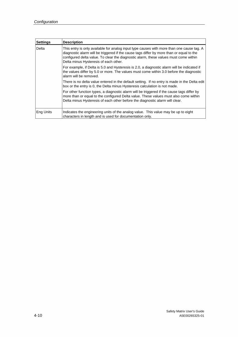
Delta This entry is only available for analog input type causes with more than one cause tag. A diagnostic alarm will be triggered if the cause tags differ by more than or equal to the configured delta value. To clear the diagnostic alarm, these values must come within Delta minus Hysteresis of each other. For example, if Delta is 5.0 and Hysteresis is 2.0, a diagnostic alarm will be indicated if the values differ by 5.0 or more. The values must come within 3.0 before the diagnostic alarm will be removed. There is no delta value entered in the default setting. If no entry is made in the Delta edit box or the entry is 0, the Delta minus Hysteresis calculation is not made. For other function types, a diagnostic alarm will be triggered if the cause tags differ by more than or equal to the configured Delta value. These values must also come within Delta minus Hysteresis of each other before the diagnostic alarm will clear.
Eng Units Indicates the engineering units of the analog value. This value may be up to eight characters in length and is used for documentation only.
Configuration
Safety Matrix User's Guide A5E00265325-01 4-11
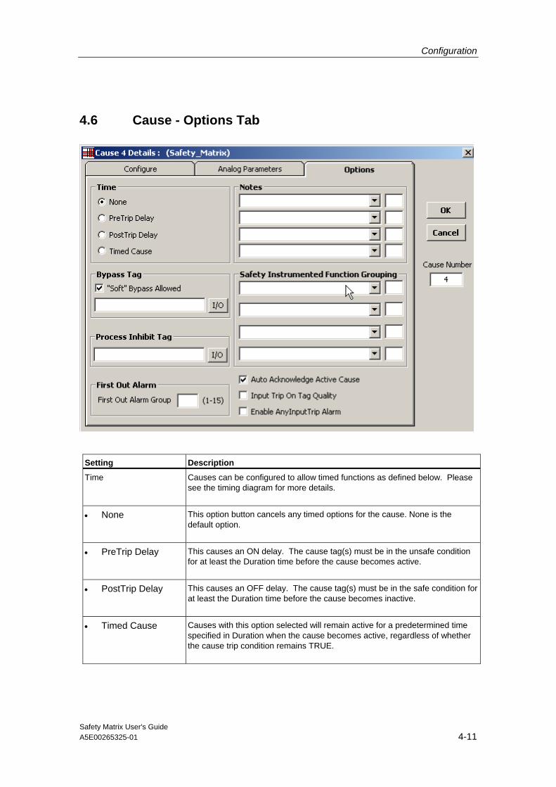
4.6 Cause - Options Tab
Setting Description
Time Causes can be configured to allow timed functions as defined below. Please see the timing diagram for more details.
• None This option button cancels any timed options for the cause. None is the default option.
• PreTrip Delay This causes an ON delay. The cause tag(s) must be in the unsafe condition for at least the Duration time before the cause becomes active.
• PostTrip Delay This causes an OFF delay. The cause tag(s) must be in the safe condition for at least the Duration time before the cause becomes inactive.
• Timed Cause Causes with this option selected will remain active for a predetermined time specified in Duration when the cause becomes active, regardless of whether the cause trip condition remains TRUE.
Configuration
Safety Matrix User's Guide 4-12 A5E00265325-01
Setting Description
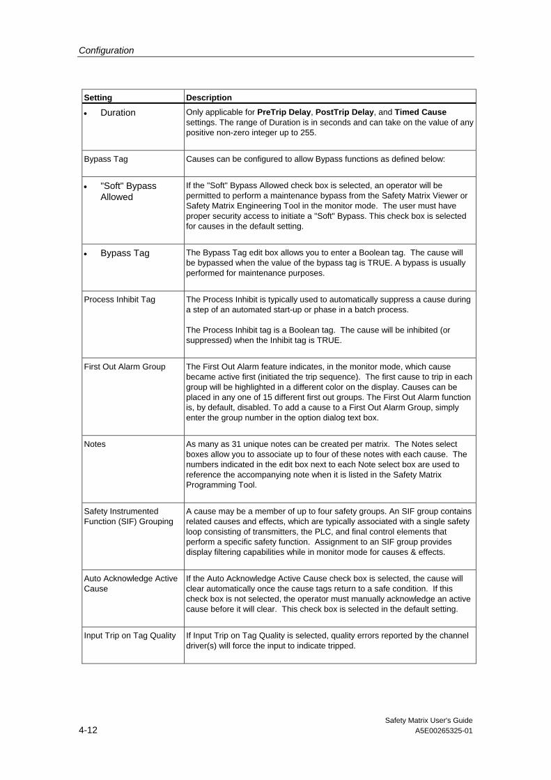
• Duration Only applicable for PreTrip Delay, PostTrip Delay, and Timed Cause settings. The range of Duration is in seconds and can take on the value of any positive non-zero integer up to 255.
Bypass Tag Causes can be configured to allow Bypass functions as defined below:
• "Soft" Bypass Allowed
If the "Soft" Bypass Allowed check box is selected, an operator will be permitted to perform a maintenance bypass from the Safety Matrix Viewer or Safety Matrix Engineering Tool in the monitor mode. The user must have proper security access to initiate a "Soft" Bypass. This check box is selected for causes in the default setting.
• Bypass Tag The Bypass Tag edit box allows you to enter a Boolean tag. The cause will be bypassed when the value of the bypass tag is TRUE. A bypass is usually performed for maintenance purposes.
Process Inhibit Tag The Process Inhibit is typically used to automatically suppress a cause during a step of an automated start-up or phase in a batch process. The Process Inhibit tag is a Boolean tag. The cause will be inhibited (or suppressed) when the Inhibit tag is TRUE.
First Out Alarm Group The First Out Alarm feature indicates, in the monitor mode, which cause became active first (initiated the trip sequence). The first cause to trip in each group will be highlighted in a different color on the display. Causes can be placed in any one of 15 different first out groups. The First Out Alarm function is, by default, disabled. To add a cause to a First Out Alarm Group, simply enter the group number in the option dialog text box.
Notes As many as 31 unique notes can be created per matrix. The Notes select boxes allow you to associate up to four of these notes with each cause. The numbers indicated in the edit box next to each Note select box are used to reference the accompanying note when it is listed in the Safety Matrix Programming Tool.
Safety Instrumented Function (SIF) Grouping
A cause may be a member of up to four safety groups. An SIF group contains related causes and effects, which are typically associated with a single safety loop consisting of transmitters, the PLC, and final control elements that perform a specific safety function. Assignment to an SIF group provides display filtering capabilities while in monitor mode for causes & effects.
Auto Acknowledge Active Cause
If the Auto Acknowledge Active Cause check box is selected, the cause will clear automatically once the cause tags return to a safe condition. If this check box is not selected, the operator must manually acknowledge an active cause before it will clear. This check box is selected in the default setting.
Input Trip on Tag Quality If Input Trip on Tag Quality is selected, quality errors reported by the channel driver(s) will force the input to indicate tripped.

Configuration
Safety Matrix User's Guide A5E00265325-01 4-13
Setting Description
Enable Any Input Trip Alarm
If a cause is configured with multiple inputs, the user can select whether an alarm will be indicated if any of the inputs have met the cause trip request criteria. By default, Discrete and Analog inputs are configured as defined below: • Discrete defaulted to Disabled • Analog defaulted to Enabled
Timing Diagram for Cause Time Functions
Normal Cause(no time function)
Cause Active
Pre-Trip Delay Cause configured duration
CauseActive
Post Trip Delay Cause configured duration
Cause Active
Timed Cause configured duration
Cause Active

Configuration
Safety Matrix User's Guide 4-14 A5E00265325-01
4.7 Adding and Editing Effects
4.7.1 Adding an effect
1. Double-click anywhere on the Effects section of a blank column. If there are no blank columns in the matrix, you can add a column by increasing the size of the matrix.
2. To increase the size of the matrix, select View>Options. The Matrix Options dialog box will be displayed.
3. Type the desired value in the Number of Effects edit box. The maximum size of any matrix is 128 x 128.
Note
An empty Effect column can be added to the matrix by selecting Insert Column from the Edit menu. If there are no blank columns in the matrix, inserting an additional effect column will cause the last column in the matrix to be shifted out (deleted). Use the Select Display Options dialog box to increase the size of a matrix before using the Insert Column command.

Configuration
Safety Matrix User's Guide A5E00265325-01 4-15
4.7.2 Editing an effect
1. Double-click on any cell in the effect portion of a column. The Configuration for Effect # dialog box will be displayed. This dialog box can also be accessed by right-clicking the effect and selecting Edit Effect from the pop-up menu.
2. When adding or editing an effect, an effect description must be entered and at least one tag specified.
3. Once the tags have been entered, the effects options for all tag types should be evaluated and set appropriately.

Configuration
Safety Matrix User's Guide 4-16 A5E00265325-01
4.8 Effect - Configure Tab
Fields Description
Effect Number This is a unique number assigned to each effect. This number is assigned automatically based on the column selected. The effect number cannot be changed from this dialog box.
Desc (Description) This is an alpha/numeric description of the effect, and can be up to 32 characters in length. The description is a required field.
Configuration
Safety Matrix User's Guide A5E00265325-01 4-17
Fields Description
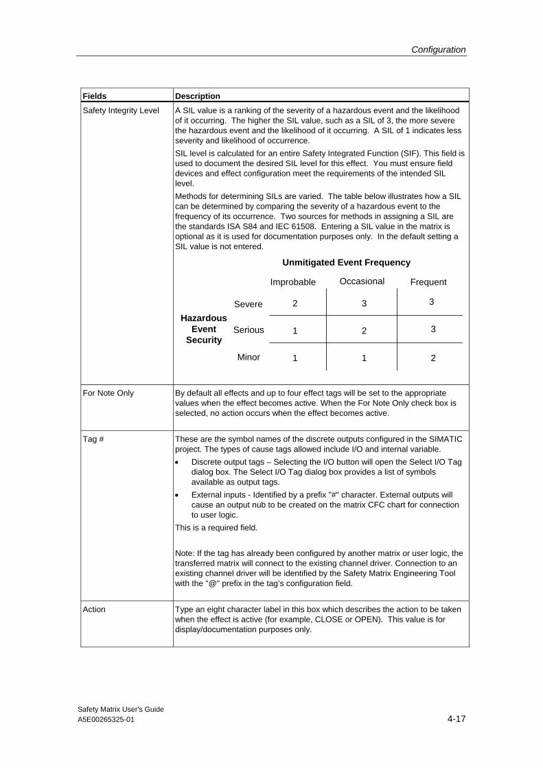
Safety Integrity Level A SIL value is a ranking of the severity of a hazardous event and the likelihood of it occurring. The higher the SIL value, such as a SIL of 3, the more severe the hazardous event and the likelihood of it occurring. A SIL of 1 indicates less severity and likelihood of occurrence. SIL level is calculated for an entire Safety Integrated Function (SIF). This field is used to document the desired SIL level for this effect. You must ensure field devices and effect configuration meet the requirements of the intended SIL level. Methods for determining SILs are varied. The table below illustrates how a SIL can be determined by comparing the severity of a hazardous event to the frequency of its occurrence. Two sources for methods in assigning a SIL are the standards ISA S84 and IEC 61508. Entering a SIL value in the matrix is optional as it is used for documentation purposes only. In the default setting a SIL value is not entered.
Severe
Serious
Minor
HazardousEvent
Security
1 1
1
2
2
2
3
33
Improbable Occasional Frequent
Unmitigated Event Frequency
For Note Only By default all effects and up to four effect tags will be set to the appropriate
values when the effect becomes active. When the For Note Only check box is selected, no action occurs when the effect becomes active.
Tag # These are the symbol names of the discrete outputs configured in the SIMATIC project. The types of cause tags allowed include I/O and internal variable. • Discrete output tags – Selecting the I/O button will open the Select I/O Tag
dialog box. The Select I/O Tag dialog box provides a list of symbols available as output tags.
• External inputs - Identified by a prefix "#" character. External outputs will cause an output nub to be created on the matrix CFC chart for connection to user logic.
This is a required field. Note: If the tag has already been configured by another matrix or user logic, the transferred matrix will connect to the existing channel driver. Connection to an existing channel driver will be identified by the Safety Matrix Engineering Tool with the "@" prefix in the tag’s configuration field.
Action Type an eight character label in this box which describes the action to be taken when the effect is active (for example, CLOSE or OPEN). This value is for display/documentation purposes only.

Configuration
Safety Matrix User's Guide 4-18 A5E00265325-01
Fields Description
Energize-To-Trip Output
If this box is checked, the effect tag will be energized (set to TRUE) when the effect is active. The value of an effect tag is normally de-energized (set to FALSE) when the effect is active. Effect tags that are set to Energize-To-Trip are indicated in the Safety Matrix with an asterisk on the effect tag. This check box is not selected in the default setting.
4.9 Effect - Options Tab
Field Description
Output Delay If the Enabled check box is selected, the output(s) will be set to the failsafe value(s) after a time delay. The length of the delay in seconds is specified by the value entered in the Delay Output edit box. To clear a previously configured delay, set Delay Output to zero, and clear the Enable Process Pass Through check box.
Bypass Tag Effects can be configured to allow Bypass functions as defined below:
Configuration
Safety Matrix User's Guide A5E00265325-01 4-19
Field Description
"Soft" Bypass Allowed If the "Soft" Bypass Allowed check box is selected, an operator will be permitted to perform a maintenance bypass from the Safety Matrix Viewer or Safety Matrix Engineering Tool in the monitor mode. The user must have proper security access to initiate a "Soft" Bypass. This check box is clear for effects in the default setting.
Bypass Tag The Bypass Tag edit box allows you to select or enter a Boolean I/O tag. The effect will be bypassed when the value of the bypass tag is TRUE. A bypass is usually performed for maintenance purposes.
Reset/Override Tag The effect can be placed in Override when using V or R type intersections, or the effect can be Reset when using S or R type intersections. The Effect will be reset when the tag has a FALSE to TRUE transition. In the case of overrides, a FALSE to a TRUE transition will toggle the override state. Refer to Intersection Types section for details.
Maximum Override Time This edit box allows the user to set the maximum time, in seconds, that the effect can be left in override. If the conditions that trigger the effect still exist after the maximum override time has elapsed, the effect will become active again and an "Override Failed Time Out" alarm will be reported. If a "New Cause" becomes active that is attached to this effect, the Override will stop and the effect will become active again and a "Override Failed New Cause" alarm will be reported. The configured Maximum Override Time should not be greater than the duration of any condition that the process or plant can tolerate.
Masking or Process Pass Through
Enable Process Pass Through
This check box indicates the effect is to be configured to allow process pass through. Configuring an effect to allow process pass through requires a "Process Data Tag" to be specified. See description of Process Pass Through below.
Mask Enable Tag The value of the Mask Enable Tag determines whether the effect logic or an externally controlled process variable (refer to Process Data Tag, below) is connected to the effect’s output tags. See description of Masking below.
Process Data Tag Identifies an external process variable that will be written to the effect's output when the effect is not active. This allows an output to be controlled by a process value until an unsafe condition activates the effect and makes the effect go to its configured safe state. When a Mask Enable Tag is configured and enabled, this value will always be written to the output tags. For Energize-To-Trip (ETT) discrete output tags, the value of the Process Data Tag is inverted before being written to the Output tags.
Safety Instrumented Function Grouping
An effect may be a member of up to four safety groups. An SIF group contains related causes and effects, which are typically associated with a single safety loop consisting of transmitters, the PLC, and final control elements that perform a specific safety function. Assignment to an SIF group provides display filtering of causes & effects.

Configuration
Safety Matrix User's Guide 4-20 A5E00265325-01
Field Description
Notes As many as 31 unique notes can be created per matrix. The Notes select boxes allow you to associate up to four of these notes with each effect. The numbers indicated in the edit box next to each Note select box are used to reference the accompanying note when it is listed in the Safety Matrix Programming Tool.

Configuration
Safety Matrix User's Guide A5E00265325-01 4-21
Process Pass Through Process Pass Through is a concept that allows an externally controlled process variable (from a control system) to be connected into the effect's output logic. Process Pass Through will be overridden by the matrix if the effect becomes active. The process pass through is configured by checking the "Enable Process Pass Through" box and specifying a "Process Data Tag" for the process variable.
Note
When using Process Pass Through, the "Mask Enable Tag" entry should not be configured.
The pass through is controlled by the effect's active state, see figure below. The value of the Process Data Tag will be connected to the output tags whenever the effect logic is not active. In the event the effect logic becomes active, the Process Data Tag value is disconnected from the effect's output tags and the failsafe value drives the output. The failsafe value for a De-energize-To-Trip (DTT) output is FALSE, and for an Engergize-To-Trip (ETT) output is TRUE.
Process Data Tag value
Effect Failsafe value Output Tags
Distributed Control System
Effect In-active
Configuration
Safety Matrix User's Guide 4-22 A5E00265325-01
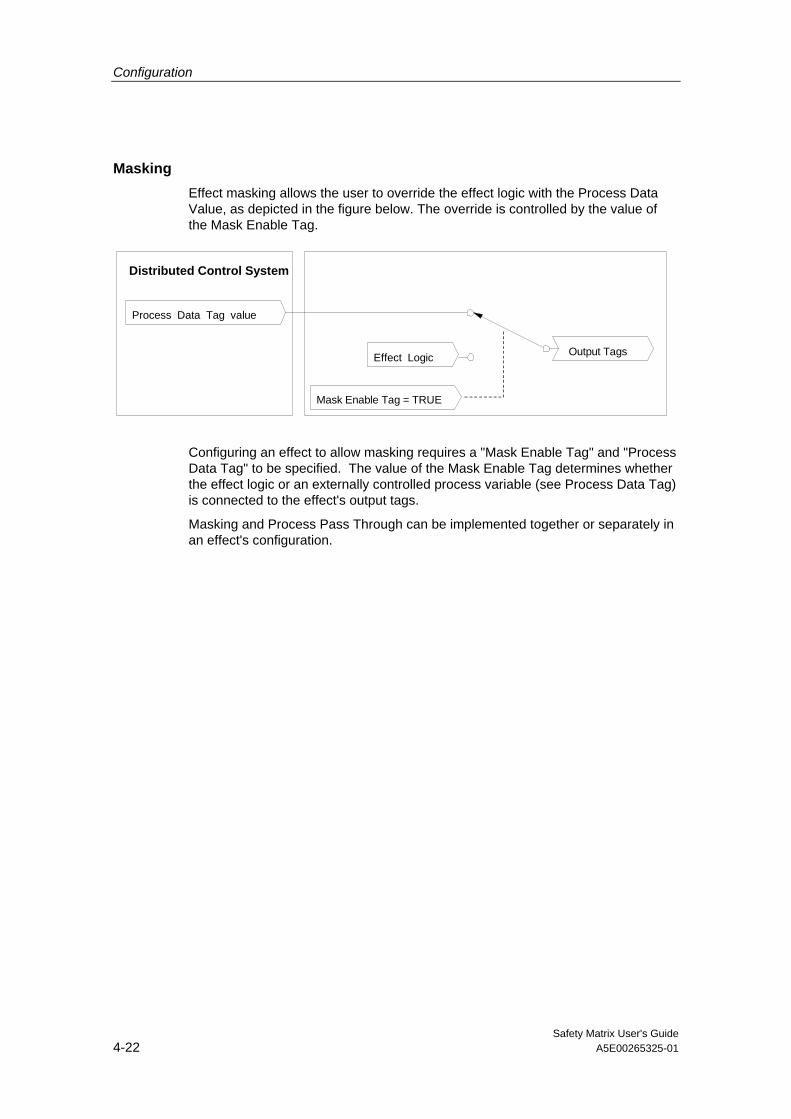
Masking Effect masking allows the user to override the effect logic with the Process Data Value, as depicted in the figure below. The override is controlled by the value of the Mask Enable Tag.
Process Data Tag value
Effect Logic Output Tags
Distributed Control System
Mask Enable Tag = TRUE
Configuring an effect to allow masking requires a "Mask Enable Tag" and "Process Data Tag" to be specified. The value of the Mask Enable Tag determines whether the effect logic or an externally controlled process variable (see Process Data Tag) is connected to the effect's output tags.
Masking and Process Pass Through can be implemented together or separately in an effect's configuration.
Configuration
Safety Matrix User's Guide A5E00265325-01 4-23
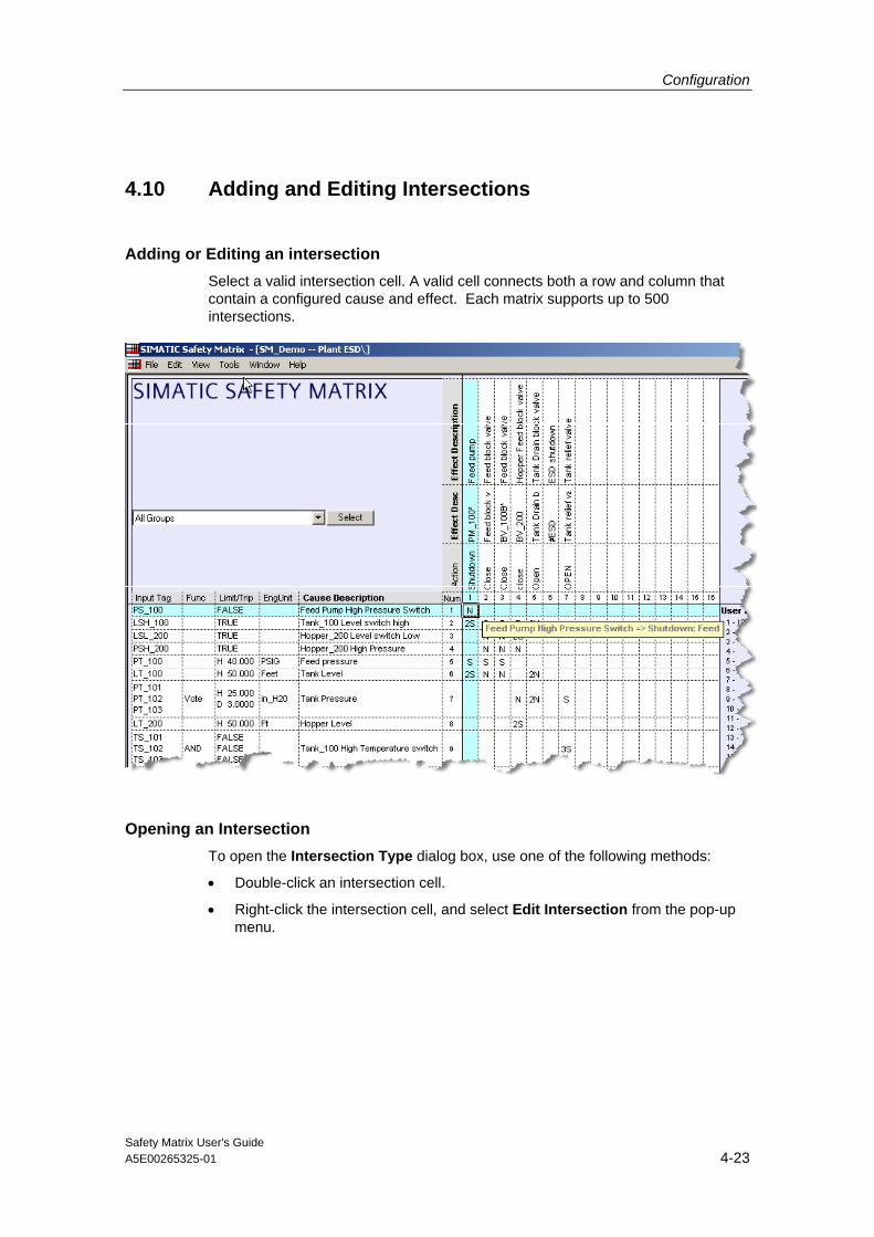
4.10 Adding and Editing Intersections
Adding or Editing an intersection Select a valid intersection cell. A valid cell connects both a row and column that contain a configured cause and effect. Each matrix supports up to 500 intersections.
Opening an Intersection To open the Intersection Type dialog box, use one of the following methods:
• Double-click an intersection cell.
• Right-click the intersection cell, and select Edit Intersection from the pop-up menu.

Configuration
Safety Matrix User's Guide 4-24 A5E00265325-01
4.11 Intersection Type Dialog Box
Field Description
N - Not-Stored A simple pass-through function. If the cause is active, the effect is triggered.
S - Set-Stored If the cause is active, the effect is triggered and stored (latched). When the effect is no longer triggered, the effect must be cleared manually by the operator or by setting the configured Reset/Override tag TRUE.
V - Override If the cause is active, the effect is triggered. The effect may be overridden manually by the operator or by setting the configured Reset/Override tag TRUE while the effect is still triggered. This allows you to reintegrate your system if an effect output is holding a cause active.
R - Resetable Override An intersection of this type combines the characteristics of both the S and V types defined above. Effects connected to this intersection will remain latched when the associated cause becomes inactive, but may be overridden.
None There is not an association between this cause and this effect (no entry in the intersection). This is the default intersection type.
X - Not Specified Some association is required between the cause and effect, but the desired intersection type has not yet been determined. No association will be processed until the intersection type has been entered. A matrix with an X intersection cannot be transferred to the controller.
* - For Note Only No association is processed between this cause and this effect. For documentation purposes only.
Configuration
Safety Matrix User's Guide A5E00265325-01 4-25
Field Description
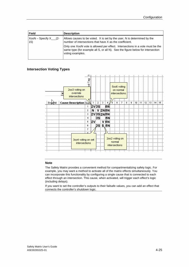
XooN – Specify X___(2-15)
Allows causes to be voted. X is set by the user, N is determined by the number of intersections that have X as the coefficient. Only one XooN vote is allowed per effect. Intersections in a vote must be the same type (for example all S, or all N). See the figure below for intersection voting examples.
Intersection Voting Types
Note
The Safety Matrix provides a convenient method for compartmentalizing safety logic. For example, you may want a method to activate all of the matrix effects simultaneously. You can incorporate this functionality by configuring a single cause that is connected to each effect through an intersection. This cause, when activated, will trigger each effect’s logic (including delays). If you want to set the controller’s outputs to their failsafe values, you can add an effect that connects the controller’s shutdown logic.

Configuration
Safety Matrix User's Guide 4-26 A5E00265325-01
4.12 Editing General Information
The Safety Matrix Engineering Tool supports general information documentation for each matrix.
To open the General Information dialog box, select View>General Information
Field Description
Title Enter a title to identify the matrix.
Project Enter the title of the project the matrix belongs to, if applicable.
Description Enter a description of the matrix as it relates to the process.

Configuration
Safety Matrix User's Guide A5E00265325-01 4-27
Field Description
General Notes Enter general notes which describe this particular matrix.
User Notes These are notes that you can associate with certain causes and/or effects. Up to 31 notes can be entered. A limit of four notes can be assigned to each cause and effect. Each note supports a string length of up to 60 characters.
Major Revisions Drop down box for viewing the major revision history.
Safety Instrumented Function Groups
Allows you to specify a description for the causes and effects associated with a single safety loop or desired display view. In the Safety Matrix Engineering Tool and Safety Matrix Viewer, the display can then be filtered to display only those Safety Instrumented Function Groups which interest you. This can be configured by the user.
Matrix Cycle Time (ms) Allows you to specify the cycle time of the controller in which the matrix will be transferred. Use the drop-down menu to select from available times (all in ms). These cycle times pertain to the execution times of OBs 30 thru 38. Note As with conventional S7 F System logic programming, using channel drivers from another OB is possible. To connect to a channel driver in another OB, create external inputs for the matrix and use RTG to RTG communications.
Statistics Displays basic information about the number of elements configured in the matrix.
Major Revision • Next Major Rev
- Revision - TimeStamp
Allows you to increment the major revision. The major revision number and time stamp of the revision change are displayed in the General Information dialog box. When you make a major revision, you are prompted to enter a comment describing the revision.
Minor Revision • Next Minor Rev
- Revision - TimeStamp
Allows you to increment the minor revision. The minor revision number and time stamp of the revision change are displayed in the General Information dialog box. The Minor Revision number is reset to zero when the Major Revision number is incremented. Each time the matrix is saved, you will be prompted to increment the minor revision.
Matrix File Revision - Revision - TimeStamp
Provides a revision and time stamp of when the matrix file was last saved.
Path to Matrix File Identifies the location of the file that stores the matix’s configuration.
Path to SIMATIC Project Identifies the SIMATIC project that the matrix is associated with.
Logical Path to S7 Program Identifies the path in the SIMATIC Component View to the matrix.
Matrix in Plant Hierarchy Identifies the path in the SIMATIC Plant View to the matrix.

Configuration
Safety Matrix User's Guide 4-28 A5E00265325-01
4.13 Matrix Project Utilities
When you have finished configuring a Safety Matrix, it must be saved and transferred to the project before it can be compiled and downloaded for execution in the controller.
Transferring the matrix to a project 1. Select Tools->Project Utilities.
2. Select Transfer To Project. Transferring the matrix to the project’s Safety Program is password protected. Enter the Safety Program password when prompted.
During the transfer, the Safety Matrix Engineering Tool validates the matrix for configuration warnings, such as causes without intersections or effects without reset tags and errors, such as multiple effects with the same output tag. The results of the validation reports are displayed in the log window.
3. If the validation checks pass, the Safety Matrix Engineering Tool performs a comparison between the current matrx and the project’s saved matrix.

Configuration
Safety Matrix User's Guide A5E00265325-01 4-29
Differences are displayed in the log window. The user is prompted to review the changes prior to continuing the transfer.
The transfer operation will create a chart in the SIMATIC project with the same name as the matrix. The chart has a locked chart (@MatrixName ) that contains the entire configuration of the matrix. A second chart (MatrixName) contains automatic connections to the channel drivers.
The channel driver chart has two inputs. The ACK_REI input connects to all internal channel driver ACK_REI inputs. This input is not intended for customer use. The Safety matrix chart will issue the ACK_REI after receiving the command from the Safety Matrix Engineering Tool.
The PASS_ON input connects to all internal channel driver PASS_ON inputs. It is intended for customer use.
The channel driver chart has a single output. The ACK_REQ output is BOOLEAN created by an ORing all the channel driver ACK_REQ outputs. This is used to indicate that at least one of the channel drivers is requesting to be re-integrated. The request for the ACK is passed up to the Safety Matrix chart to the Safety Matrix Engineering Tool and Safety Matrix Viewer.
In a typical configuration, the Safety Matrix chart has a single input, ACK_REQ, that is driven by the channel driver chart’s ACK_REQ output.
Five outputs are provided for customer use:
- Error – Boolean flag indicating that a configuration error has been detected.
- Alarm – Boolean flag indicating an alarm condition has been detected.
- Any_CA – Indicates that at least one of the causes in the matrix is active.
- Any_EA - Indicates that at least one of the effects in the matrix is active.
- CByp_Num – Integer value indicating the number of causes currently being bypassed.
- EByp_Num - Integer value indicating the number of effects currently being bypassed.
Additional inputs will be present if the user has configured input tags with a "#" prefix. Similarly, The user can route outputs from the matrix to chart logic by configuring tags with a "#" suffix.
The figure below is the chart generated during the transfer for a matrix named "SM_Demo". The charts show the configured external cause input (#RESET) and effect output (#ESD). Connect the external inputs and outputs to user logic before compiling.

Configuration
Safety Matrix User's Guide 4-30 A5E00265325-01
Note
Once you have transferred a matrix to the project, use the Tools>Compare>Compare with Project function to confirm that the project's configuration is consistent with the matrix.
Note
To ensure proper Safety Matrix monitoring functionality, do not change the names of the charts created during the matrix transfer.
Compiling the SIMATIC project Press the Compile button on the Project Utilities dialog box, or from other SIMATIC applications.
Once the project has been successfully compiled, it can be downloaded to the controller.
Downloading the SIMATIC project to the controller Press the Download button on the Project Utilities dialog box, or from other SIMATIC applications. The matrix logic can then be validated for proper functionality.

Safety Matrix User's Guide A5E00265325-01 5-1
5 Operation
5.1 Viewing a Safety Matrix in Monitor Mode
Monitor mode in the Safety Matrix Engineering Tool allows you to monitor real-time values, and view the status of a matrix that has been downloaded to the controller.
Entering Monitor Mode To enter monitor mode, select Tools>Start Monitoring menu item.
The Safety Matrix Engineering Tool will connect to the Safety Matrix function block in the controller or simulator. Once connected, active causes and effects are highlighted in red.
See Also Safety Matrix Menu Options Section for details on the Matrix Options dialog box.

Operation
Safety Matrix User's Guide 5-2 A5E00265325-01
5.2 Color Status Indicators
The colors displayed in Safety Matrix monitor mode indicate the status of the causes, intersections, and effects. These colors are predefined, and cannot be configured by the user.
Color Status
Red Cause/Effect Active
Magenta Bypass Active or Tag Disabled
Yellow Inhibit/Mask Active
Brown Effect Override Active
Green Safe to Reset Effect
Cyan First Out Alarm Active
Blue Click View Status button
Operation
Safety Matrix User's Guide A5E00265325-01 5-3
5.3 Controlling the System in Monitor Mode
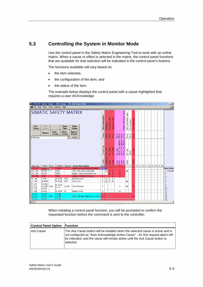
Use the control panel in the Safety Matrix Engineering Tool to work with an online matrix. When a cause or effect is selected in the matrix, the control panel functions that are available for that selection will be indicated in the control panel’s buttons.
The functions available will vary based on:
• the item selected,
• the configuration of the item, and
• the status of the item.
The example below displays the control panel with a cause highlighted that requires a user ACKnowledge.
When initiating a control panel function, you will be prompted to confirm the requested function before the command is sent to the controller.
Control Panel Option Function
Ack Cause The Ack Cause button will be enabled when the selected cause is active and is not configured as "Auto Acknowledge Active Cause". An Ack request alarm will be indicated, and the cause will remain active until the Ack Cause button is selected.

Operation
Safety Matrix User's Guide 5-4 A5E00265325-01
Control Panel Option Function
Clear First Out Clear First Out indicates which cause was first to trigger the associated First Out Alarm Group. The first out cause will be highlighted in cyan until the cause and the Clear First Out button are selected.
Bypass The Bypass button prevents a cause or effect from becoming active. If a cause is bypassed, it will not become active. If an effect is bypassed, its effect tags are forced to their operating values. Activating a bypass action requires a password, which you will be prompted to type in the dialog box that is displayed by clicking the Bypass button. Before the bypass is initiated, you are prompted to enter a reason for the maintenance bypass. Information entered in the dialog box is logged in the Event Logger for future reference.
View Events The Safety Matrix has event recording built into its standard functionality. The event recording functionality allows the matrix to store event information based on cause and effect status changes. The event recording supports 200 events. When the number of events exceeds the buffer size, the oldest events will be overwritten. This method ensures that the most current events are retained for viewing. The View Events function will cause the Safety Matrix Engineering Tool to read the events from the controller and display them in the Events window. Reference the description for the cause and effect status details for information on which user operations and diagnotstic events are logged.
Clear Events The Clear Events function will cause the Safety Matrix in the controller to clear
its event log.

Operation
Safety Matrix User's Guide A5E00265325-01 5-5
Control Panel Option Function
Bypass Report The Bypass Report function creates a list of all causes and effects that are in bypass, and all tags that are currently disabled. The results are displayed in the Log window. The Bypass Report below shows Cause 1 and Effect 4 in bypass and Cause 7’s tag 1 "PT_101" disabled.
View Status If a cause or an effect is selected, the View Status button will be available.
Selecting this button will display the Cause Status Detail or Effect Status Detail dialog box. These dialog boxes contain information on the current settings of the matrix features for the selected cause or effect. Changes cannot be made in these dialog boxes. If an item is highlighted in white, the item is selected or active. Each entry in the dialog box represents a status/error bit for the selected cause or effect. Refer to the cause and effect status details below.
View Tags The View Tags function displays a dialog box that allows you to view the values of cause or effect tags, disable a tag in the controller, and view or change scaling ranges for analog I/O tags. See the topic Entering Maintenance Changes below.
Clear Alarm The Clear Alarm function will be enabled when an effect is selected that was in override, but has become active again because: • the configured Maximum Override Time has elapsed. • it has been re-triggered by a new active cause. In these cases, an alarm will be indicated on the effect. The Clear Alarm button must be clicked to clear the alarm indication.
Reset Effect/Override Effect
The text on this button will be either Reset Effect or Override Effect depending on the status of the selected effect.
• Reset Effect If an effect is triggered by a Set-Stored (S) or Resetable/Override(R) type intersection, the effect will latch. This means that the effect will stay active even when it is no longer triggered by the cause. The effect may be unlatched (reset) when it is no longer triggered. To unlatch the effect, click the Reset Effect function. This function will only be available if the selected effect is eligible to be reset (indicated by green in the default color settings).
Operation
Safety Matrix User's Guide 5-6 A5E00265325-01
Control Panel Option Function
• Override Effect If an effect is triggered by an oVerride (V) or a Resetable/Override (R) intersection, the effect output tag(s) may be returned to the operating value(s) while the effect is still triggered. This action is called an override. If the selected effect is eligible to be overridden, the override function will be available. Click the Override Effect function to return the effect tag(s) to their operating values.
Note The duration of the effect override may not exceed the Maximum Override Time defined in the effect options. If another cause (connected to the effect) becomes active during the override, the override will immediately stopped.

Operation
Safety Matrix User's Guide A5E00265325-01 5-7
Cause Status Details
Cause Status Description Event
Recorded Click
View Status
Cause Active Indicates that all configured criteria have been met (state, function logic, delays, etc.) to allow the active state.
X
Timed Active Indicates that a configured time delay is currently active. When the delay expires, the Delay Active bit will be cleared.
Hysteresis Active Indicates that an active cause has come out of its trip condition, but is still within its configured deadband.
Inhibit Active Indicates that the cause has been inhibited by the configured inhibit tag.
X
Bypass Active Indicates the cause is currently being bypassed. X Soft Bypass Active Indicates that the current bypass was initiated from
theSafety Matrix Engineering Tool or Safety Matrix Viewer. X
Trip Requested Indicates the cause function logic (AND, OR, Voting) has been satisfied. The cause active state may still be affected by the configured timing delays, bypassing, inhibit and latching.
Delta Alarm (TagX – TagY)
Indicates that the calculated tag difference (X – Y) has exceeded the configured delta alarm value.
X
Any Input Trip Alarm In a multi-tag cause, this status indicates that at least one of the tags has met the trip condition and is requesting a trip.
X

Operation
Safety Matrix User's Guide 5-8 A5E00265325-01
Cause Status Description Event Recorded
Click View Status
Illegal Config Error Internal diagnostic check performed by the FB (e.g Undefined function type).
X
SDF Error Indicates that the matrix has detected a Safety Data Format (SDF) error.
X
Active Ack Required Indicates that the cause will be latched active until both the user acknowledges it, and the trip condition is removed.
X X
Tag # Trip Request Indicates the configured tag has met the trip request requirement. This status incorporates the tag’s Energize-To-Trip configuration.
X
Tag # Value Indicates the configured tag state. Tag # Bad Quality Indicates that the configured tag’s channel driver is
reporting a quality alarm. X
Tag # Disabled Indicates that the configured tag has been disabled. X Tag # Channel Failure
Indicates the configured tag’s channel driver is reporting a channel failure.
X
Tag # ProfiSafe Failure
Indicates that the configured tag’s channel driver is reporting a Profibus failure, originating in the module driver.
X

Operation
Safety Matrix User's Guide A5E00265325-01 5-9
Effect Status Details
Effect Status Description Event
Recorded Click
View Status
Effect Active Indicates that all configured criteria have been met (intersection state, delays, bypass, etc.) to allow the active state.
X
Delay Active Indicates a delay is currently active. Mask Active Indicates masking is currently active. X Override Active Indicates an override is currently active. X N Intersections Indicates a connected N-type intersection is active. S Intersections Indicates a connected S-type intersection is active. V Intersections Indicates a connected V-type intersection is active. R Intersections Indicates a connected R-type intersection is active. Bypass Active Indicates a bypass is currently active. X Soft Bypass Active Indicates that the current bypass was initiated from the
Safety Matrix Engineering Tool or Safety Matrix Viewer. X
Pass Thru Active Indicates a process pass through is active in the effect logic.
X
Override Input Indicates the effect is currently being overriden.

Operation
Safety Matrix User's Guide 5-10 A5E00265325-01
Effect Status Description Event Recorded
Click View Status
Ok to Override Indicates the effect is ready to be overridden. Ok to Reset Indicates the effect is ready to be reset. Effect Latched Indicates the effect is latched. Override Failed NewCause
Indicates the override of the effect has been interrupted by a new cause becoming active.
X
Override Failed Timeout
Indicates the override of the effect has timed out. X
Illegal Config Error Internal diagnostic check performed by the FB (e.g Undefined function type).
X
SDF Error Indicates that the matrix has detected a Safety Data Format (SDF) error.
X
Tag # Value Indicates the current state of the configured output tag. Tag # Bad Quality Indicates that the configured tag’s channel driver is
reporting a quality alarm. X
Tag # Disabled Indicates the tag has been disabled. X Tag # Channel Failure
Indicates the configured tag’s channel driver is reporting a channel failure.
X
Tag # ProfiSafe Failure
Indicates that the configured tag’s channel driver is reporting a Profibus failure, originating in the module driver.
X

Operation
Safety Matrix User's Guide A5E00265325-01 5-11
5.4 Entering Maintenance Changes in Monitor Mode
Disable a tag, and write to values in the controller 1. In the View Tags dialog box, check the Enable Maintenance Changes check
box.
2. Select the Disable button for the associated tag. You will be prompted for a reason, which is recorded with the event.
Once the tag is disabled, analog tags can be modified by entering a REAL number in the value box and selecting the Write button. The new value will be sent to the controller. Discrete tags can be similarly modified by selecting the TRUE or FALSE buttons.
Note
Disabling tags within a matrix is subject to the following limitations:
• If the tag’s channel driver was configured for this matrix, disabling the tag will affect any users of the tag. This includes other matrices and any user configured logic. A channel driver that was not configured for this matrix will be identified with the "@" prefix in the tag configuration field.
• If the tag’s channel driver is from Failsafe Blocks (V1_2), the disable function will be restricted within the matrix. This means that if the channel is shared with any logic outside of the matrix, that logic will not be disabled and will "see" the value of the physical I/O.
Operation
Safety Matrix User's Guide 5-12 A5E00265325-01
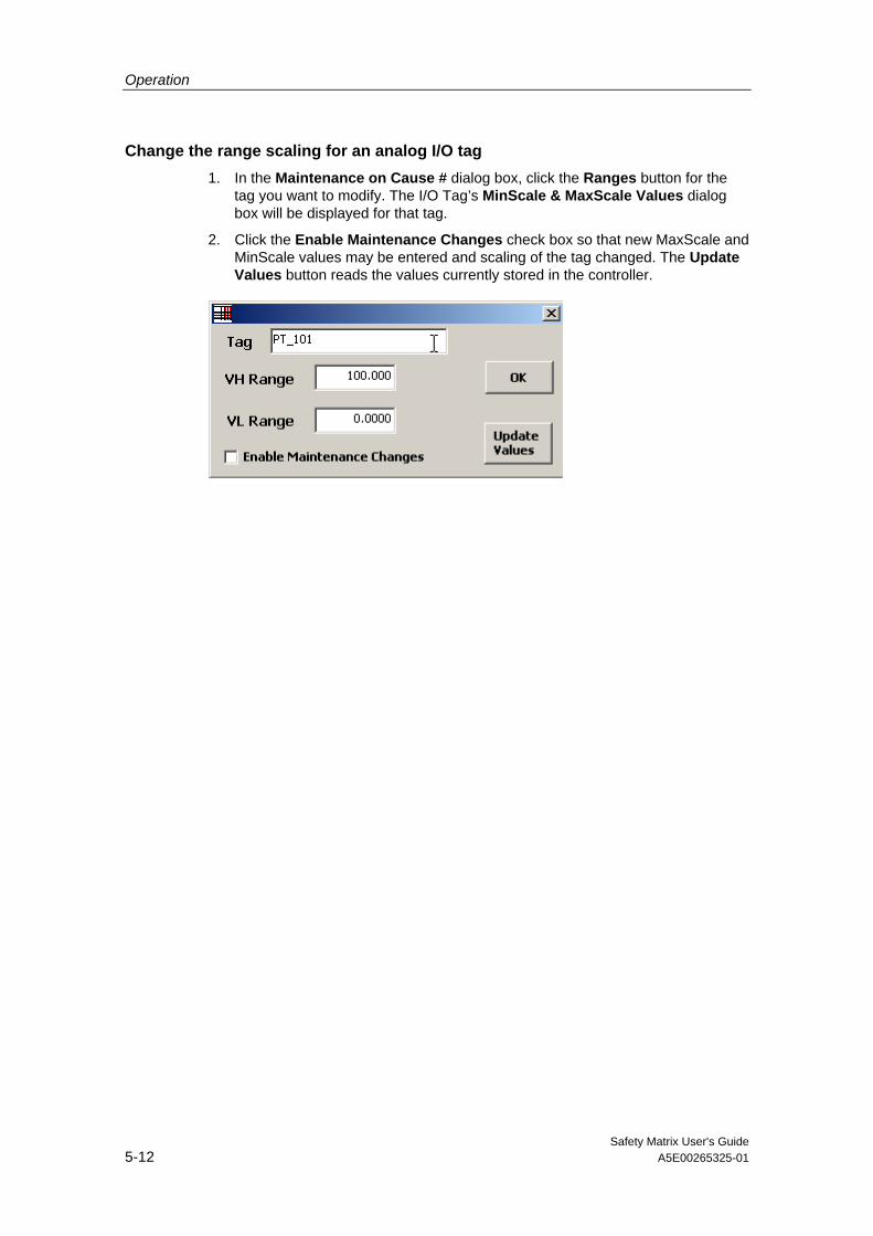
Change the range scaling for an analog I/O tag 1. In the Maintenance on Cause # dialog box, click the Ranges button for the
tag you want to modify. The I/O Tag’s MinScale & MaxScale Values dialog box will be displayed for that tag.
2. Click the Enable Maintenance Changes check box so that new MaxScale and MinScale values may be entered and scaling of the tag changed. The Update Values button reads the values currently stored in the controller.

Operation
Safety Matrix User's Guide A5E00265325-01 5-13
5.5 Making Changes In Monitor Mode
While a matrix is running in the controller, it is possible to make changes to the Limit, Hysteresis, and Delta configuration parameters of analog causes in monitor mode.
Modifying a parameter, 1. Double-click the analog cause in the Limit/Trip cell. The Perform Online
Changes dialog box will open.
2. Enter the analog parameter(s) to modify in the New Value text box(es).
3. Click the OK button to send the change to the controller.
Operation
Safety Matrix User's Guide 5-14 A5E00265325-01
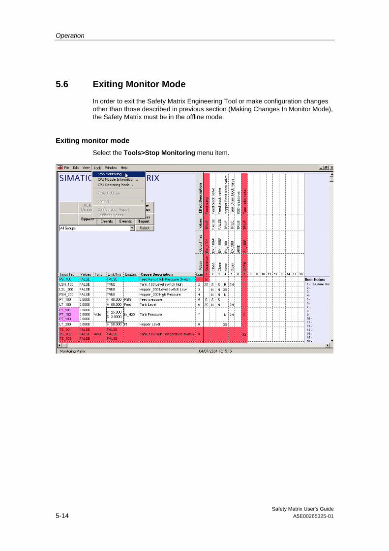
5.6 Exiting Monitor Mode
In order to exit the Safety Matrix Engineering Tool or make configuration changes other than those described in previous section (Making Changes In Monitor Mode), the Safety Matrix must be in the offline mode.
Exiting monitor mode Select the Tools>Stop Monitoring menu item.

Safety Matrix User's Guide A5E00265325-01 6-1
6 Safety Matrix Menu Options
This section contains a list of the menu options available in the Safety Matrix Engineering Tool dialog box with a description of how these options are used in configuring a Safety Matrix.

Safety Matrix Menu Options
Safety Matrix User's Guide 6-2 A5E00265325-01
6.1 File Menu
Command Function
New Opens an empty matrix with the name NewMatrix.cem as a read-only file. Use the Save command to assign a file name to the new matrix.
Open... Displays the Open dialog box for selecting and opening a previously configured matrix. Use this option to open a matrix you want to edit.
Close Closes the current matrix file. You are prompted to save any changes you have made to the matrix before closing.
Save Saves the current matrix to a file. If you are saving changes to a matrix, the new matrix will replace the older version. If you are overwriting a matrix in a project, you will be prompted to clear the change marks, increment the minor revision and supply the Safety Program password. No password is required when you save to a new file.
Save As... Saves the matrix to a different file.
Print Preview Displays a preview of the log file to be printed.
Print... Opens the Print dialog box. The Print dialog box allows the current matrix to be printed in its graphic form or previewed. The Print command is only available in the offline mode.
Exit Closes all dialog boxes and exits the program. The Exit command is only available in the offline mode.
Safety Matrix Menu Options
Safety Matrix User's Guide A5E00265325-01 6-3
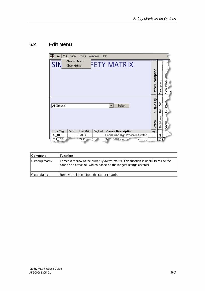
6.2 Edit Menu
Command Function
Cleanup Matrix Forces a redraw of the currently active matrix. This function is useful to resize the cause and effect cell widths based on the longest strings entered.
Clear Matrix Removes all items from the current matrix.
Safety Matrix Menu Options
Safety Matrix User's Guide 6-4 A5E00265325-01
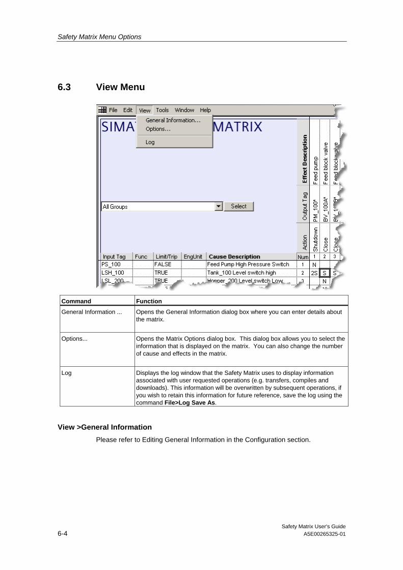
6.3 View Menu
Command Function
General Information ... Opens the General Information dialog box where you can enter details about the matrix.
Options... Opens the Matrix Options dialog box. This dialog box allows you to select the information that is displayed on the matrix. You can also change the number of cause and effects in the matrix.
Log Displays the log window that the Safety Matrix uses to display information associated with user requested operations (e.g. transfers, compiles and downloads). This information will be overwritten by subsequent operations, if you wish to retain this information for future reference, save the log using the command File>Log Save As.
View >General Information Please refer to Editing General Information in the Configuration section.

Safety Matrix Menu Options
Safety Matrix User's Guide A5E00265325-01 6-5
View>Options
Field Description
Matrix Size • Number of Causes By default there are 16 causes, enter the number of causes to be
displayed up to 128.
• Number of Effects By default there are 16 effects, enter the number of effects to be displayed up to 128.
Show C/E Options Displays the options selected for the cause or effect on the safety matrix. The list below shows the abbreviations that are used in this field. This list is also displayed in the lower, right corner of the matrix. I – Inhibit Configured M – Mask Configured B – Maintenance Bypass N – Non-Standard I/O Used (Not an I/O Tag) P – Process Data Pass-Through Used A – Auto Cause Acknowledge Used
Show C/E Notes Displays numbers of the notes that have been assigned to this cause or effect. The notes that correspond to each number are listed on the right side of the matrix.
Show C/E SIL Displays the Safety Integrity Level (SIL) number that was assigned to this cause or effect.
Safety Matrix Menu Options
Safety Matrix User's Guide 6-6 A5E00265325-01
Field Description
Show Safety/First Out Groups Displays the first out and/or safety groups to which this cause or effect is assigned. The First Out group is indicated by the abbreviation "FO". For example, FO2 indicates that the cause is a member of First Out (FO) group 2. Safety group numbers are listed after the First Out number. For example, FO3, 5, 17, 44 indicate that this cause is a member of First Out (FO) group 3, and safety groups 5, 17, and 44.
Show Reset/Override Tag Displays the reset/override tag assigned to the effect.
Show I/O Physical Address in View Tags
Displays the physical I/O address along with the symbol reference in the View Tags dialog box.
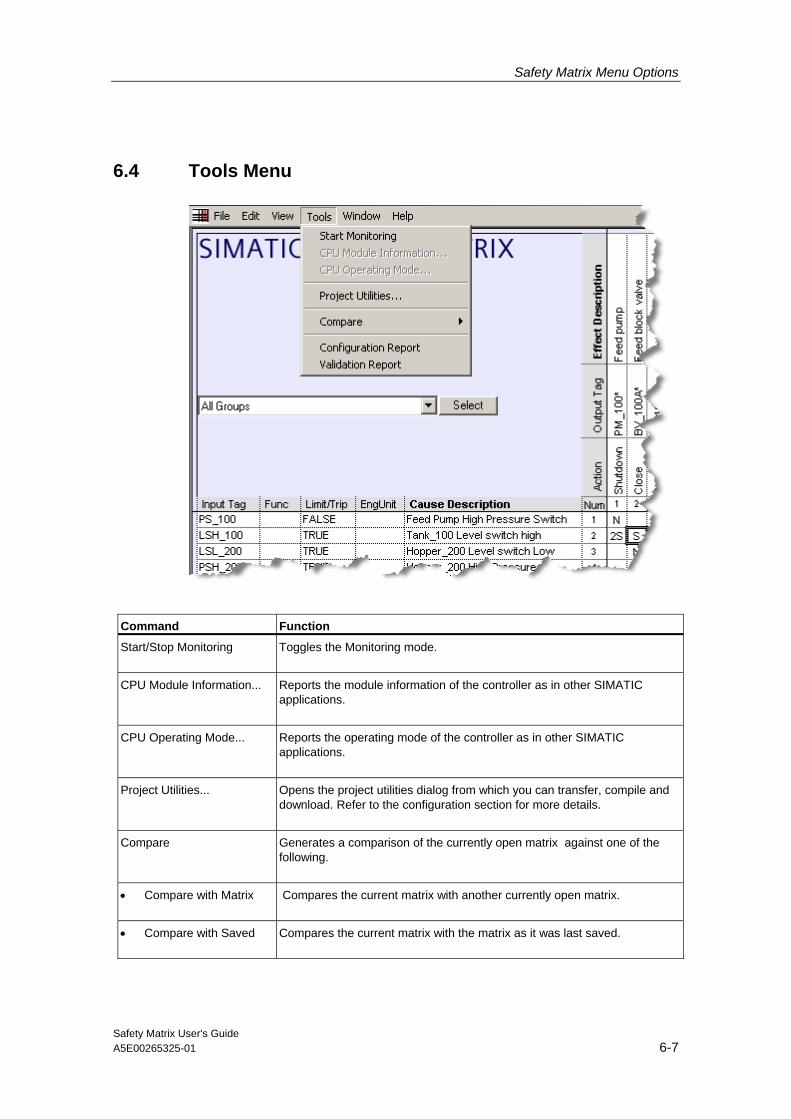
Safety Matrix Menu Options
Safety Matrix User's Guide A5E00265325-01 6-7
6.4 Tools Menu
Command Function
Start/Stop Monitoring Toggles the Monitoring mode.
CPU Module Information... Reports the module information of the controller as in other SIMATIC applications.
CPU Operating Mode... Reports the operating mode of the controller as in other SIMATIC applications.
Project Utilities... Opens the project utilities dialog from which you can transfer, compile and download. Refer to the configuration section for more details.
Compare Generates a comparison of the currently open matrix against one of the following.
• Compare with Matrix Compares the current matrix with another currently open matrix.
• Compare with Saved Compares the current matrix with the matrix as it was last saved.

Safety Matrix Menu Options
Safety Matrix User's Guide 6-8 A5E00265325-01
Command Function
• Compare with Project Compares the current matrix against the last matrix transferred to the project.
• Compare with PLC Compares the current matrix against the matrix compiled and downloaded in the controller.
Configuration Report Generates a report of the entire matrix configuration in the log window.
Validation Report Runs a configuration check on the matrix, and displays the results in the log window.

Safety Matrix Menu Options
Safety Matrix User's Guide A5E00265325-01 6-9
6.5 Window Menu
Command Function
Tile Horizontal If more than one window is open, this command will arrange the windows tiled horizontally.
Tile Vertical If more than one window is open, this command will arrange the windows tiled vertically.
Cascade If more than one window is open, this command will arrange the windows in a cascade manner.
Arrange Icons Arranges all minimized matrices along the bottom of the Safety Matrix window.
Opened Matrix List Displays a list of all currently open matrices in the lower section of the menu.
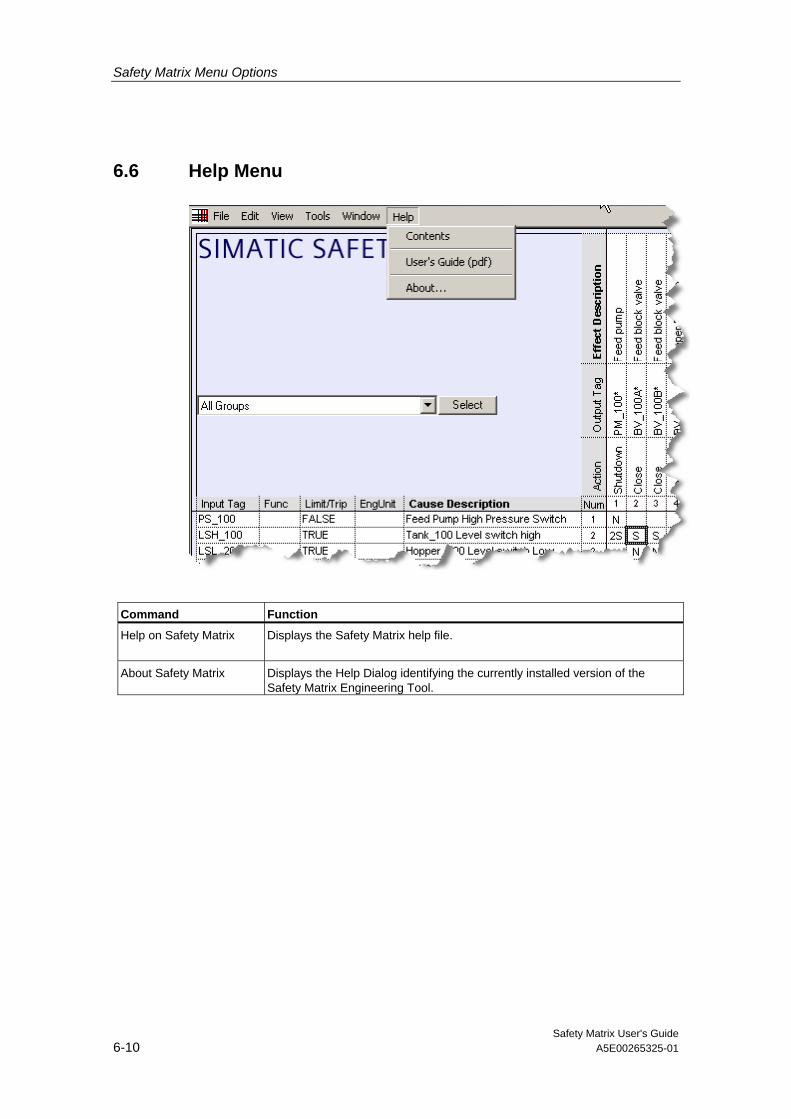
Safety Matrix Menu Options
Safety Matrix User's Guide 6-10 A5E00265325-01
6.6 Help Menu
Command Function
Help on Safety Matrix Displays the Safety Matrix help file.
About Safety Matrix Displays the Help Dialog identifying the currently installed version of the Safety Matrix Engineering Tool.

Safety Matrix User's Guide A5E00265325-01 7-1
7 Importing a Matrix File
As matrices are created and reviewed, it may be necessary to take matrix logic developed outside of a SIMATIC project and add it to the program. This is referred to as importing a matrix.
An example could be a generic Emergency Shut Down cause and effects matrix developed at a corporate research and development office and deployed to a number of sites for inclusion to a local project.
The deployment of the matrix would arrive in the form of a matrix *.CEM file. This file contains the entire configuration for a single matrix.
The following steps describe how to import the matrix into a SIMATIC project:
1. Start SIMATIC Manger.
2. Open the project to import the matrix.
3. Select Matrices>Object Properties

Importing a Matrix File
Safety Matrix User's Guide 7-2 A5E00265325-01
4. Select Import CEM File(s).
5. Double-click the desired .CEM file.

Importing a Matrix File
Safety Matrix User's Guide A5E00265325-01 7-3
6. Edit the matrix, then transfer, compile and download as described in the configuration section.

Importing a Matrix File
Safety Matrix User's Guide 7-4 A5E00265325-01

Safety Matrix User's Guide A5E00265325-01 8-1
8 Safety Matrix Viewer
8.1 Safety Matrix Viewer Prerequisites
Assumptions • A Safety Matrix has been created and transferred to a project in SIMATIC
Manager.
• The Safety Matrix has been transferred to a CFC.
• The Safety Matrix project in Simatic Manager already contains a WinCC project, with an established hierarchy of plant areas.
• The Safety Matrix help file and user's guide assumes that the user has an understanding of WinCC configuration concepts. For more details on WinCC, refer to the following manuals:
- The WinCC Information System
- The PCS 7 Operator Station Configuration Manual

Safety Matrix Viewer
Safety Matrix User's Guide 8-2 A5E00265325-01
Preparing WinCC to Create Safety Matrix Block Icons
Configuring the Safety Matrix Viewer from SIMATIC Manager involves the automatic creation of Safety Matrix Viewer Block Symbols on WinCC Pictures. To ensure the accuracy of this functionality, the following steps must be performed:
1. Launch WinCC Explorer for the OS included in the Safety Matrix project. Locate and open the following files in the Graphics Designer: @@SafetyMatrixTypicals.PDL and @PCS7Typicals.PDL
If @PCS7Typicals.PDL does not yet exist, create it by copying and renaming the @@PCS7Typicals.PDL in the same target directory.

Safety Matrix Viewer
Safety Matrix User's Guide A5E00265325-01 8-3
2. Copy the contents of the @@SafetyMatrixTypicals.PDL to an empty space on the @PCS7Typicals.PDL. Note that when the F_Matctl Block Symbol is copied, it is automatically renamed. In the figure below, the Block Symbol is renamed to "F_Matcl1".

Safety Matrix Viewer
Safety Matrix User's Guide 8-4 A5E00265325-01
3. Change the Object Name of the Block Symbol on the @PCS7Typicals.PDL to @F_Matctl/1. To do so, right-click the F_Matctl Block Symbol on the picture and select Properties. On the Properties dialog, correct the Object Name attribute.
4. Save and close the @PCS7Typicals.PDL.
5. Open the @PCS7Typicals.PDL in the \SIEMENS\WINCC\options\pdl\FaceplateDesigner_V6 directory. Repeat Steps 1, 2, 3 and 4 to create and rename an instance of the F_Matctl Block Symbol on this PDL instance. If this is done correctly, the @PCS7Typcials.PDL file will include the F_Matctl Block Symbol when future OS projects are created.

Safety Matrix Viewer
Safety Matrix User's Guide A5E00265325-01 8-5
8.2 Configuring the Safety Matrix Viewer
The Safety Matrix Viewer exists as a WinCC faceplate in the PCS 7 OS environment. In runtime, the faceplate provides an operator with the ability to read and display data values from a running Safety Matrix in a graphical format (similar to the Monitor Mode that is available from within the Safety Matrix Engineering Tool). With appropriate security rights, an operator can execute some basic matrix control functions like modifying analog tuning values, bypassing, resetting and overriding.
Configuring the Safety Matrix Viewer 1. Open the project in SIMATIC Manager.
2. Navigate to the matrix's associated CFC in the Charts folder of the Component View.
3. Cut the matrix's associated CFC from the Component View, and paste it into a hierarchy folder in the Plant View. Note that after pasting the CFC into the Plant View, it will appear in both the Component View and the Plant View.
4. Create a picture in the hierarchy folder that contains the matrix's associated CFC. In the Plant View, right-click the appropriate hierarchy folder and select Insert New Object>Picture. Assign a logical name to the picture.

Safety Matrix Viewer
Safety Matrix User's Guide 8-6 A5E00265325-01
5. Right-click the picture to open its Object Properties dialog box. On the Block symbols tab, check the following option: Derive the block symbols from the technological hierarchy. Close the dialog box.
6. Run the OS Compile operation in SIMATIC Manager by selecting Options>OS>Compile. Enable at least the following compile options:
• Tags and messages
• Picture Tree
• Create/update block icons
7. Launch the Safety Matrix application by double-clicking the appropriate object in the Matrix folder.
8. Open the Project Utilities dialog box by selecting Tools>Project Utilities. Click the Map OS Tags button to run the Safety Matrix OS Mapper. Close the dialog box when the mapping is complete.
These instructions were written for a PC that acts as both a client and server.

Safety Matrix Viewer
Safety Matrix User's Guide A5E00265325-01 8-7
8.3 Operating the Safety Matrix Viewer
At runtime, the operator can access the Safety Matrix Viewer from within WinCC. The Safety Matrix Viewer provides a visual representation of the matrix as configured and monitored in the Safety Matrix Engineering Tool. The color scheme utilized in the Safety Matrix Viewer is the same as that employed by the Monitor Mode of the Safety Matrix Engineering Tool. It is important to note that while the Safety Matrix Viewer can display the overall configuration of a matrix (including causes, effects and intersections), no configuration modifications can be made.
Note
The matrix functions available to the user in the Safety Matrix Viewer are the same as those in the Monitor Mode of the Safety Matrix Engineering Tool, with the following exception: • Bypass Report For more information, please refer to the following topics in the Operation section: • Color Status Indicators • Controlling the System in Monitor Mode • Entering Maintenance Changes in Monitor Mode • Making Change in Monitor Mode
The Safety Matrix Viewer allows for the simultaneous display and updating of multiple matrices. In addition, the Safety Matrix Viewer supports the simultaneous monitoring of the same matrix on different client stations.

Safety Matrix Viewer
Safety Matrix User's Guide 8-8 A5E00265325-01
Accessing the Safety Matrix Viewer in Run-time Mode 1. Launch WinCC Explorer for the OS included in the Safety Matrix project.
2. Click the Activate button on the WinCC Explorer toolbar to start the OS in run-time mode.
3. In WinCC Run-time, open the picture that contains the Safety Matrix Viewer symbol and associated I/O Channel Driver symbols (if configured).
4. The Safety Matrix Viewer symbol includes the following data:
• The Safety Matrix tag name
• The number of Cause Bypasses
• The number of Effect Bypasses
• Indication of Any Active Cause
• Indication of Any Active Effect
• Indication of Alarms
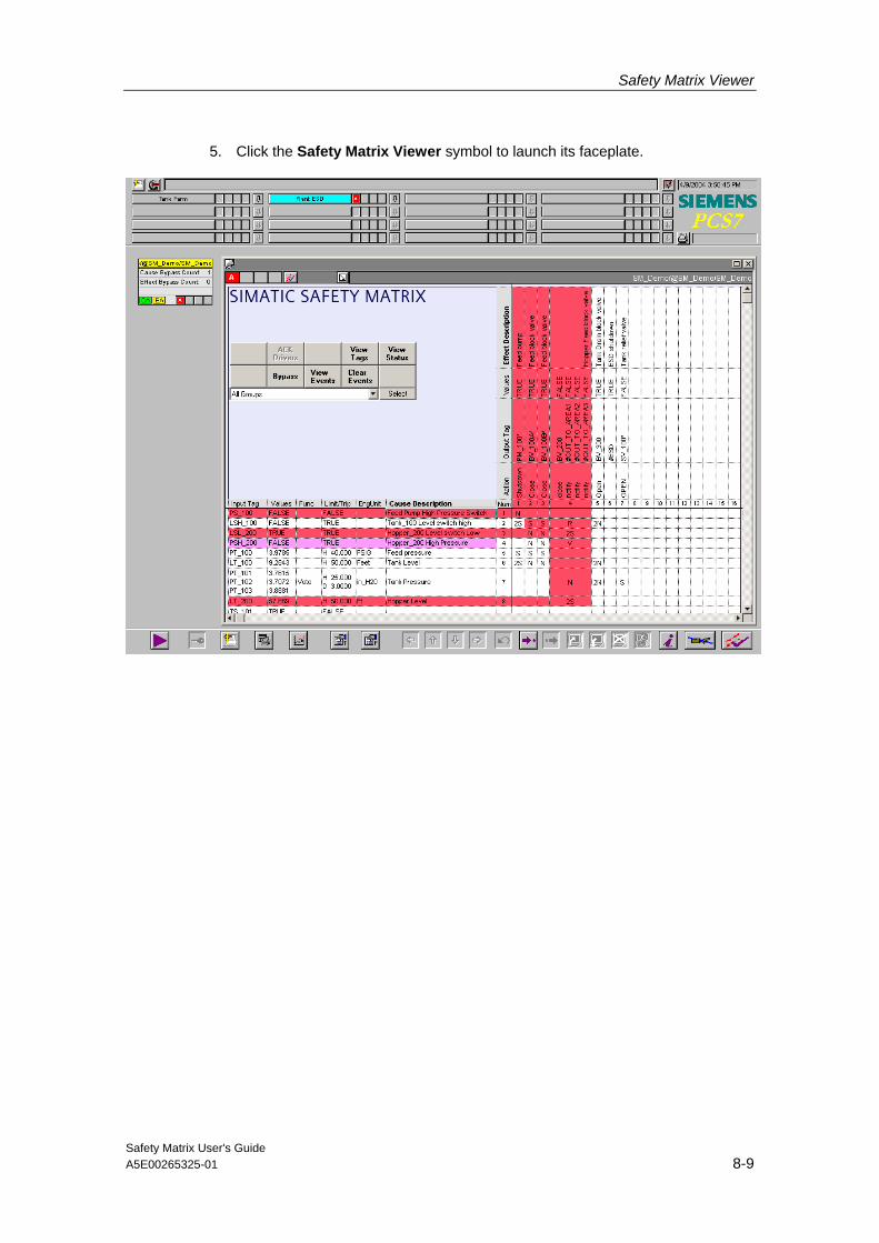
Safety Matrix Viewer
Safety Matrix User's Guide A5E00265325-01 8-9
5. Click the Safety Matrix Viewer symbol to launch its faceplate.
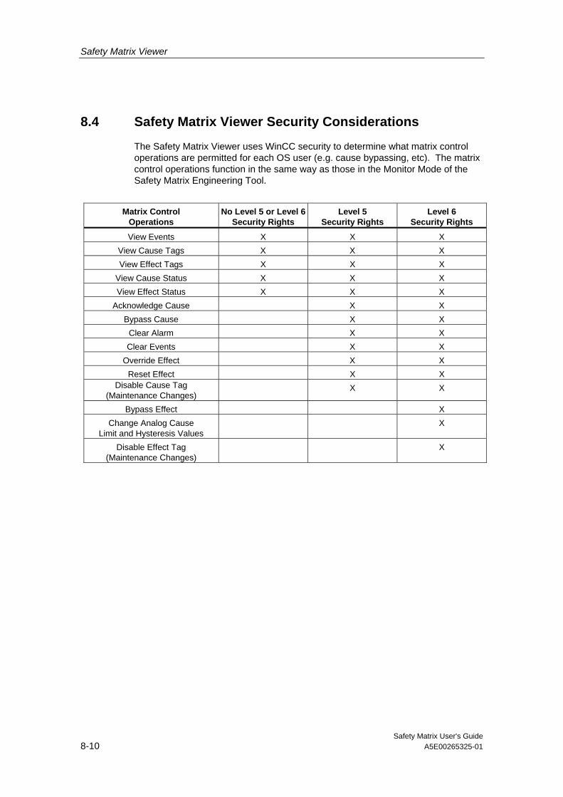
Safety Matrix Viewer
Safety Matrix User's Guide 8-10 A5E00265325-01
8.4 Safety Matrix Viewer Security Considerations
The Safety Matrix Viewer uses WinCC security to determine what matrix control operations are permitted for each OS user (e.g. cause bypassing, etc). The matrix control operations function in the same way as those in the Monitor Mode of the Safety Matrix Engineering Tool.
Matrix Control
Operations No Level 5 or Level 6
Security Rights Level 5
Security Rights Level 6
Security Rights
View Events X X X View Cause Tags X X X View Effect Tags X X X
View Cause Status X X X View Effect Status X X X
Acknowledge Cause X X Bypass Cause X X
Clear Alarm X X Clear Events X X
Override Effect X X Reset Effect X X
Disable Cause Tag (Maintenance Changes)
X X
Bypass Effect X Change Analog Cause
Limit and Hysteresis Values X
Disable Effect Tag (Maintenance Changes)
X

Safety Matrix User's Guide A5E00265325-01 9-1
9 Safety Matrix Editor
The Safety Matrix Editor is a subset of the Safety Matrix Engineering Tool. Its capabilities are limited to the configuration of a matrix outside of the SIMATIC environment. The Safety Matrix Editor is intended to support reviewing of cause and effect logic in remote workstations.
For example, an engineer at a Safety Matrix Engineering Tool workstation may create the initial version of a Safety Matrix. The matrix’s logic can be saved and shared for review locally via network, or sent as an e-mail to a colleague across the globe. The reviewer, using the Safety Matrix Editor can open the matrix and view it in the same format as the originator. The reviewer can modify the matrix configuration (e.g. change function types, timing parameters, add revision notes, etc.) and save. A matrix can also originate from the Safety Matrix Editor.
In either case, the matrix can be forwarded to an engineer working with the Safety Matrix Engineering Tool for incorporation into a SIMATIC Project.
The following Safety Matrix Engineering Tool features are not available in the Safety Matrix Editor:
1. Matrix Project Utilities
- Transfer to Project
- Compile
- Download
- Map OS Tags
2. CPU Information
- CPU Module Information
- CPU Operating Mode
3. Matrix Compare Functions with SIMATIC
- Compare with Project
- Compare with PLC
Opening the Safety Matrix Editor Select Start>Programs>Siemens>SafetyMatrix
Creating a New Matrix Select File>New
A dialog box will open to prompt you to enter a name for the new matrix.
By default, the location will be the installed Safety Matrix directory (C:\Siemens\SafetyMatrix). You can also select your own location for the matrix.

Safety Matrix Editor
Safety Matrix User's Guide 9-2 A5E00265325-01
Opening an Existing Matrix File Select File>Open
Navigate to the desired Matrix file.
Select the file and open it.
Editing a Matrix Once you have opened a matrix for editing, configuration in the Safety Matrix Editor operates in the same manner as the Safety Matrix Engineering Tool. Refer to the Configuration section for details.
Sharing a Matrix File When you are satisfied with the cause and effect logic, save and close the matrix.
The matrix is wholly contained in the matrix file (*.CEM). It can be moved, copied, etc. using operating system functions like any other file. The *.CEM file can be accessed from a shared location or e-mailed to another user.
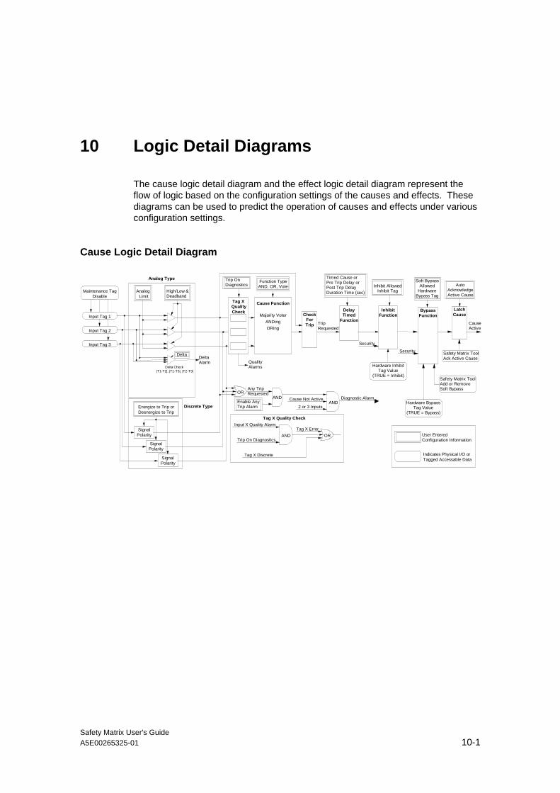
Safety Matrix User's Guide A5E00265325-01 10-1
10 Logic Detail Diagrams
The cause logic detail diagram and the effect logic detail diagram represent the flow of logic based on the configuration settings of the causes and effects. These diagrams can be used to predict the operation of causes and effects under various configuration settings.
Cause Logic Detail Diagram
Maintenance TagDisable
Input Tag 1
Input Tag 2
Input Tag 3
Energize to Trip orDeenergize to Trip
SignalPolarity
SignalPolarity
SignalPolarity
Analog Limit
High/Low &Deadband
Delta DeltaAlarm
Tag XQualityCheck
Cause Function
Majority VoterANDingORing
CheckForTrip
Function TypeAND, OR, Vote
OR
AND
DelayTimed
Function
Timed Cause orPre Trip Delay orPost Trip DelayDuration Time (sec)
TripRequested
InhibitFunction
Inhibit AllowedInhibit Tag
Analog Type
Discrete Type
Delta Check|T1-T2|, |T1-T3|, |T2-T3|
Any TripRequested
Cause Not Active
2 or 3 Inputs
ORAND
Input X Quality Alarm
Trip On Diagnostics
Tag X Error
Tag X Discrete
Tag X Quality Check
User EnteredConfiguration Information
Indicates Physical I/O orTagged Accessable Data
Soft BypassAllowed
HardwareBypass Tag
Security
Safety Matrix ToolAdd or RemoveSoft Bypass
Hardware BypassTag Value
(TRUE = Bypass)
Security
CauseActive
Diagnostic AlarmANDEnable AnyTrip Alarm
Trip OnDiagnostics
QualityAlarms
BypassFunction
Hardware InhibitTag Value
(TRUE = Inhibit)
LatchCause
AutoAcknowledgeActive Cause
Safety Matrix ToolAck Active Cause

Logic Detail Diagrams
Safety Matrix User's Guide 10-2 A5E00265325-01
Effect Logic Detail Diagram
EffectLatch
Reset/Override TagMax Override Time
TripRequestedOR
Latch Effect
AND
AND
OK to Reset
OK toOverride
Security
Any OverrideIntersection Active
New Cause Active
From Intersections
Override Failed
EffectLatched
EffectActive
DelayOutputsFunction
Delay EnabledDelay Time (sec)
Soft Bypass AllowedHardware Bypass Tag
Security
Safety Matrix ToolAdd or Remove
Soft Bypass
Reset/Override Data ValueDefined by Reset/Override Tag
Pass ThroughAllowed
Mask AllowedMaskEnable TagProcessData Tag
MaskFunction
Process Data ValuePointed to by theProcessData Tag
Hardware BypassTag Value
(TRUE = Bypass)
BypassFunction
Security
Mask Enable Data ValuePointed to by theMaskEnable Tag
Energize To Trip
InvertSignal
MaintenanceTag Disable
Output Tag 1
Output Tag 2
Output Tag 3
Output Tag 4
User EnteredConfiguration Information
Indicates Physical I/O orTagged Accessable Data
False to TrueStarts Override or
Resets Effect
Any ResetOverrideIntersection Active
Any SetIntersection Active
Any NormalIntersection Active
OR
In-Active
FailsafeOutputs
BypassActive
ProcessPass Through
Function
PassThroughActive
MaskActive
InvertSignal
InvertSignal
InvertSignal

Safety Matrix User's Guide A5E00265325-01 11-1
11 Migrating a Matrix from QUADLOG to S7 F Systems
In the SIMATIC environment all matrices are stored in the form of a *.CEM file.
In the QUADLOG Safety Matrix, matrices are stored in either *.CEM files, or exported as an *.XLS file.
The Safety Matrix Engineering Tool supports opening both SIMATIC and QUADLOG formats, which allows you to easily migrate the matrices.
Migrating a QUADLOG matrix 1. Select File>Open
2. Navigate to the desired QUALOG *.CEM or *.XLS file and select it
3. Click Open
The file is opened and you are prompted to enter a name to save the migrated file.
A validation report is automatically run on the migrated file. Some QUADLOG matrix function types are not currently supported in the SIMATIC Safety Matrix for S7 F Systems. These functions and their handling are listed below:
• Cause - Difference type are configured as Note Only
• Effect – Single Analog Output are configured as Note Only
• Effect – Proofing Output are configured as Note Only
• Global Var Tag I/O – Prefix with a "#" and brought out of the Matrix chart as an input or output.
You can now import the file into a SIMATIC project and modify the configuration as desired.


Safety Matrix User's Guide A5E00265325-01 12-1
12 Glossary
Term Definition
Bypass To prevent a cause or effect from being active. If a cause is bypassed, it will not trigger any associated effects. If an effect is bypassed, its effect tags are forced to their operating values.
Cause One or more tags whose states are combined to determine whether the cause is active or inactive.
Cause Status This is either Active or Inactive. The status of a cause is determined by the condition(s) of the cause tag(s) and the function type (e.g. AND, OR, voting) of the cause.
Cause Tag A particular tag (I/O tag or global variable) in a cause
CFC Continuous Function Chart 1. Continuous Function Chart (CFC) with the graphic interconnection of technological functions (blocks). 2. A software package (CFC editor) for plant oriented, graphic configuration of an automation task. Using CFC, ready-made blocks are put together to form an entire software structure (CFC chart).
Effect An effect occupies a column of the matrix. Ths field reflects a process action. When the effect is active, the effect tags will be set to their failsafe values.
Effect Override An action used to temporarily set the effect outputs to their operational value while connect cause is still triggered.
Effect Reset An action used to remove an effect from the latched state.
Effect Status This is either Active or Inactive. If an effect is active, its tag or group of tags is held at the failsafe values. If an effect is inactive, its tag or group of tags is allowed to move to the operating values.
Effect Tag A particular tag (I/O tag or global variable) in an effect.
First Out Alarm Group A concept that supports the assignment of a cause to a group for purposes of indicating the first to become active.
Failsafe Value The value, when written to an output tag, will put the process into a safe state when an effect is active.

Glossary
Safety Matrix User's Guide 12-2 A5E00265325-01
Term Definition
Inhibit Similar to bypassing, inhibits perform the same function, but are intended to be driven by process logic.
Intersection An intersection is the cell that is common between a cause row and an effect column. This field determines how the effect responds to the cause. If the intersection is empty, the cause does not influence the effect. If there is an N (not stored), S (set stored), V (override) or R (resetable override) in the intersection, an active cause will trigger the associated effect and the effect will become active.
Masking An action used to route a process value to the effect tags regardless of the effect active state.
Operating Value The value an output tag will have during normal operation.
Process Pass Through An action used to route a process value to the effect tags while the effect is not active.
Safe Condition The condition that exists when a cause tag is at its normal operating value or within its normal operating range.
Safety Instrumented Function (SIF) Grouping
A concept that supports grouping of causes and/or effects for the purposes of display filtering. SIF groups can be selected to focus on the display to only those causes and effects in which you are interested.
Safety Group A group of related causes and effects. The group is typically associated with a single safety loop, which consists of transmitters, the controller, and final control elements performing a specific safety function.
Triggered Condition The condition that exists when an effect has at least one active cause associated with it.
Unsafe (trip) Condition The condition that exists when a cause tag is not at its normal operating value or outside its normal operating range.
Safety Matrix User's Guide A5E00265325-01 Index-1
Index A
Adding and Editing Causes........................................................................................................................4-4 Adding and Editing Effects.......................................................................................................................4-14 Adding and Editing Intersections..............................................................................................................4-23 Analog Parameters Tab .............................................................................................................................4-9
C Cause - Analog Parameters Tab................................................................................................................4-9 Cause - Configure Tab...............................................................................................................................4-5 Cause - Options Tab................................................................................................................................4-11 Cause and Effect Matrix Methodology .......................................................................................................1-1 Color Status Indicators...............................................................................................................................5-2 Configuring the Safety Matrix Logic ...........................................................................................................4-3 Configuring the Safety Matrix Viewer.............................................................................................8-5 Controlling the System in Monitor Mode ....................................................................................................5-3 Creating a New Safety Matrix ....................................................................................................................4-1
E Edit Menu...................................................................................................................................................6-3 Editing General Information .....................................................................................................................4-26 Effect - Configure Tab..............................................................................................................................4-16 Effect Options Tab .................................................................................................................................4-18 Entering Maintenance Changes in Monitor Mode ...................................................................................5-11 Exiting Monitor Mode .......................................................................................................................5-14
F File Menu ...................................................................................................................................................6-2
G Glossary...................................................................................................................................................12-1 Guidelines For Using SIMATIC Safety Matrix For Safety Critical Functions ..............................................2-1
H Hardware Requirements ............................................................................................................................3-1 Help Menu ...............................................................................................................................................6-10
I Importing a Matrix File ...............................................................................................................................7-1 Installation ................................................................................................................................................ 3-2 Intersection Type Dialog Box ...................................................................................................................4-24 Introduction to Safety Matrix ......................................................................................................................1-1
L Logic Detail Diagrams..............................................................................................................................10-1

Index
Safety Matrix User's Guide Index-2 A5E00265325-01
M Making Changes In Monitor Mode ...........................................................................................................5-13 Matrix Project Utilities ..............................................................................................................................4-28 Migrating a Matrix from QUADLOG to S7 F Systems ..............................................................................11-1 Mode of Operation .....................................................................................................................................1-4
O Operating the Safety Matrix Viewer ...........................................................................................................8-7
P Matrix Project Utilities ..............................................................................................................................4-28 Product Overview.......................................................................................................................................1-5
S Safety Matrix Editor ...................................................................................................................................9-1Safety Matrix Menu Options .....................................................................................................................6-1 Safety Matrix Overview ..............................................................................................................................1-2 Safety Matrix Viewer Prerequisites ............................................................................................................8-1 Safety Matrix Viewer Security Considerations .........................................................................................8-10 Software Requirements .............................................................................................................................3-1
T Tools Menu ................................................................................................................................................6-7
V View Menu .................................................................................................................................................6-4 Viewing a Safety Matrix In Monitor Mode...................................................................................................5-1
W Window Menu ..........................................................................................................................................6-9