Human Body Posture Tracking Using Flexible, Wireless and ...
Predator: A Posture Tracking System - TI.com · We make a distinction between posture tracking and...
22
Introducing A Vision-Based Posture Tracking System Using the TMS320C40 DSP APPLICATION BRIEF: SPRA191 Authors: Jitendra Malik, Professor of Computer Science Ali Rahimi Michael Shilman Department of Computer Science University of California at Berkeley Digital Signal Processing Solutions August 1997
Transcript of Predator: A Posture Tracking System - TI.com · We make a distinction between posture tracking and...

Introducing A Vision-BasedPosture Tracking SystemUsing the TMS320C40 DSPAPPLICATION BRIEF: SPRA191
Authors: Jitendra Malik, Professor of Computer Science
Ali Rahimi Michael Shilman
Department of Computer Science University of California at Berkeley
Digital Signal Processing Solutions August 1997

IMPORTANT NOTICE
Texas Instruments (TI) reserves the right to make changes to its products or to discontinue any semiconductorproduct or service without notice, and advises its customers to obtain the latest version of relevant informationto verify, before placing orders, that the information being relied on is current.
TI warrants performance of its semiconductor products and related software to the specifications applicable atthe time of sale in accordance with TI’s standard warranty. Testing and other quality control techniques areutilized to the extent TI deems necessary to support this warranty. Specific testing of all parameters of eachdevice is not necessarily performed, except those mandated by government requirements.
Certain application using semiconductor products may involve potential risks of death, personal injury, orsevere property or environmental damage (“Critical Applications”).
TI SEMICONDUCTOR PRODUCTS ARE NOT DESIGNED, INTENDED, AUTHORIZED, OR WARRANTEDTO BE SUITABLE FOR USE IN LIFE-SUPPORT APPLICATIONS, DEVICES OR SYSTEMS OR OTHERCRITICAL APPLICATIONS.
Inclusion of TI products in such applications is understood to be fully at the risk of the customer. Use of TIproducts in such applications requires the written approval of an appropriate TI officer. Questions concerningpotential risk applications should be directed to TI through a local SC sales office.
In order to minimize risks associated with the customer’s applications, adequate design and operatingsafeguards should be provided by the customer to minimize inherent or procedural hazards.
TI assumes no liability for applications assistance, customer product design, software performance, orinfringement of patents or services described herein. Nor does TI warrant or represent that any license, eitherexpress or implied, is granted under any patent right, copyright, mask work right, or other intellectual propertyright of TI covering or relating to any combination, machine, or process in which such semiconductor productsor services might be or are used.
Copyright © 1997, Texas Instruments Incorporated

TRADEMARKS
TI is a trademark of Texas Instruments Incorporated.
Other brands and names are the property of their respective owners.

kluge

ContentsAbstract......................................................................................................................... 7Introduction .................................................................................................................. 8Hardware..................................................................................................................... 10Algorithm .................................................................................................................... 12
Filtering .................................................................................................................. 12Region Growing...................................................................................................... 12Finding Correspondences....................................................................................... 13Finding the Front-Most Regions.............................................................................. 14Grouping Regions to Form a Body.......................................................................... 14Skeletonization ....................................................................................................... 15Member Identification ............................................................................................. 18Fitting ..................................................................................................................... 18
Support Software ....................................................................................................... 19Further Work............................................................................................................... 20Conclusion.................................................................................................................. 21Team Background ...................................................................................................... 22

FiguresFigure 1. Predator Components .....................................................................................11Figure 2. Loop on a Body - Placing an Arm on the Loop in the Skeleton ........................14Figure 3. Local 3x3 Matrix Used to Determine Criticality of a Point in a Member ............16
Introducing A Vision-Based Posture Tracking System Using the TMS320C40 DSP 7
Introducing A Vision-Based PostureTracking System Using the
TMS320C40 DSP
Abstract
The fields of telepresence and virtual reality have experienced asurge of activity in recent years. The goal of these fields is to placeusers in an immersive environment that behaves like the real world.To achieve this goal, fields require the use of next-generation inputdevices such as data gloves, head-mounted displays, and variousother immersive peripherals. Posture capture and recognition offer aunified and more expressive means of interacting with computers.
This application brief presents a vision-based posture trackingsystem called Predator. Predator is a motion tracking system thatallows a computer to unintrusively analyze the posture of the subjectin real time. The package includes a vision processor based on theTexas Instruments (TI) TMS320C40 digital signal processor (DSP)and includes a library of routines that makes it easy to write softwarethat interfaces with Predator.
This document was an entry in the 1995 DSP Solutions Challenge,an annual contest organized by TI to encourage students fromaround the world to find innovative ways to use DSPs. For moreinformation on the TI DSP Solutions Challenge, see TI’s World WideWeb site at www.ti.com.

8 SPRA191
Introduction
Our basic design goal was to build a real-time posture tracker thatrequires no setup on the part of the subject being tracked and canbe used in almost any surrounding. We chose a design-basedcomputer vision because it is the only feasible technology thatallows us to track bodies while maintaining versatility andunintrusiveness. Furthermore, we have focused our design aroundtechniques and algorithms that easily lend themselves toparallelization and can execute in real time on modern parallelarchitectures
We make a distinction between posture tracking and recognition.Posture recognition determines the posture of a body by finding amatch between the visual input and the pre-recorded posturetemplates. A large amount of domain-specific information is requiredfor this type of recognition to work. Conceptually, the output of amotion recognition system is a name for the state of the body, suchas walking or sitting.
On the other hand, posture tracking requires less pre-recordedinformation to recognize human limbs and track their position. Theoutput of a tracking system consists of a stream of body jointpositions.
We believe that recognition is a simpler task than tracking whenvision is involved. Much more information is available in arecognition system and fewer states of the body are meaningful andneed to be analyzed. In contrast, a tracker must he able to analyzeevery pose the body takes on without any prejudice regarding thelikelihood of some poses over others.
Our focus was to allow Predator to perform its task in real timewithout requiring the actor to wear any special gear or undergo aninitialization protocol and still make a minimum number ofassumptions about the surroundings of the actor.
Several attempts at satisfying these goals have been made by othergroups, but no solution has successfully included real-timeprocessing while simultaneously remaining passive and unintrusive.To date, vision-based solutions have either made limitingassumptions about the scene or used techniques and algorithmsthat render real-time implementations unfeasible using today’shardware.
For example, First Sight, one of the best-known vision-basedposture trackers, decomposes the body into primitives that do notlend themselves to real-time analysis with today's hardware. Someresearchers have attempted to fit deformable body models onto theactor's posture, but these deformable model techniques also preventreal-time processing.

Introducing A Vision-Based Posture Tracking System Using the TMS320C40 DSP 9
Others have suggested that the actor perform a ritual dance in frontof the camera to help identify limbs and determine a model for thebody before the tracking begins. Some research has focused on themodeling stage, but little successful work has been done on actualtracking once the parts have been identified.
Other technologies have been successfully applied to posturetracking. One common real-time approach uses infrared sensorsinstead of cameras and requires the subject to wear infraredreflectors on critical parts of his body (such as the joints).
The most widely used technique is based on magnetic field theory.These systems track motion by detecting the orientation andposition of receivers placed on an actor's body with respect to afixed transmitter placed near the actor. The Flock of Birds is perhapsthe best known and most widely used motion capture system on themarket. The transmitters are about the size of a die and connectedto processing units by cable. The Flock requires the scene floor tobe scattered with transmitters, since the transmission rangebetween transmitters and receivers is limited to about three feet,which would prohibit the actor from move around.
Both approaches usually provide very high throughput: 30 framesper second for infrared systems and about 120 samples per secondfor magnetic systems.
However, today's motion capture solutions share the sameshortcoming: each requires the actor to he equipped withcumbersome devices. This requirement is inconvenient and timeconsuming, especially considering that the cables connecting thereceivers to the processing units in magnetic-based system areabout as thick as a telephone backbone cables.
Our approach provides a passive means of capturing human motionwithout the clutter of the paraphernalia required by other systems.We achieve this result admittedly at the expense of some accuracy,but complete passiveness seems a worthwhile trade. Predator alsohas the potential to track multiple subjects simultaneously, a featurethat other systems cannot deliver without additional hardware.
10 SPRA191
Hardware
Predator is composed of several pieces of hardware, each of whichplays a role in the transformation from visual data to jointinformation. A typical setup consists of
� Color CCD cameras positioned around the scene
� TMS320C40 parallel DSP
� Host machine to control the TMS320C40
� Client machine to make use of the joint data
Predator can make use of stereoscopic cameras when thebackground is heavily cluttered or changing or the cameras arestationary. It can also accommodate monoscopic cameras when thebackground is static and enough contrast exists between the actorand the background. Regardless of the option, several cameras areneeded to deal with the occlusion often present in one view. Thetask of disambiguating occluded postures becomes much easieronce several views are available.
The TMS320C40 parallel DSP is a collection of 8 TMS320C40 TIMmodules mounted on VME motherboards manufactured by TraquairData Systems. Other components of the TMS320C40 parallel DSPinclude a power supply and ventilation. We optimized the connectiontopology of the processor network for stereoscopic processing withonly one pair of cameras, since we have not yet implementedocclusion reasoning on our TMS320C40 prototype.
We use an IBM ThinkPad equipped with a Traquair ISA C40rnotherboard to boot the TMS320C40 network, perform furtherprocessing on the data, and transmit the joint information to a client.The ThinkPad and its onboard C40 perform reasoning based onmotion history and interpolate between data sets when the parallelprocessor is unable to provide accurate data at a high enough rate.The package joint information is then sent over the network to theclient machine or machines.
Everything below and including the host machine is considered partof the Predator system. The client machines can use the trackinginformation provided by Predator for a variety of applications asdescribed before. We are building a virtual volleyball environment asa sample application. Figure 1 graphically summarizes a typicalsetup.

Introducing A Vision-Based Posture Tracking System Using the TMS320C40 DSP 11
Figure 1. Predator Components
Note: From right to left: The cameras, TMS320C40 parallel DSP, machine, and client.
12 SPRA191
Algorithm
In a way, one can think of Predator as performing a transformationon visual input. From one end, Predator takes in video data fromcameras. From the other end, Predator returns joint positioninformation. Internally, this transformation is implemented as aseries of stages, each one providing the input for a successivestage. Our description of the process focuses on using only one pairof stereo cameras. We also briefly glance at the monoscopic versionof Predator. We do not cover multiple cameras because we have notyet fully investigated their use in handling occlusion.
The stereo processing pipeline performs region analysis on the inputimages and determines the front-most object by grouping regionstogether. By using the disparity between the two stereo views, theprocessing pipeline then skeletonizes the region corresponding tothe body and identifies the limbs by wing-specific knowledge of thehuman body. These steps are described in detail in the followingsections.
Filtering
The images are first passed through a lowpass filter to smooth outthe image. We also subsample the image to convert it to a lowerresolution. Converting the image to a lower resolution speeds upprocessing a great deal in the following stages. The high-resolutionimage can still he used in later stages for improved accuracy.
Region Growing
We sweep the image from one corner to the opposite corner, left toright, and top to bottom, recursively marking adjacent pixels ofsimilar color with a tag unique to the region. We close off the imagewhenever a pixel is examined with color that is dissimilar to the colorof the region. Once an entire region is identified, the sweepcontinues where it left off last by initiating a new floodfill whenever itreaches an untagged pixel.
The floodfill itself consists of a depth-first traversal of the image. Apixel is tagged with the region's marker only if its RGB values fallwithin a certain range of the mean RGB values of the current branchof the traversal. If the pixel is tagged, the average RGB values of thebranch art updated, and the process is repeated on each of its eightneighbors.
However, if the pixel's RGB values don’t fall in the required range,we return to the parent stack time, restoring the notion of the currentpixel and the mean ROB values. In this way, all adjacent pixels ofsimilar color will be interned as part of the same region.

Introducing A Vision-Based Posture Tracking System Using the TMS320C40 DSP 13
Note that a slight bias exists in our segmentation algorithm becausewe perform our sweep in a left-to-right, top-to-bottom fashion. Theaverage RGB values of each branch are biased toward the top left-most pixel in the region, because every branch must include thatpixel. Through experimentation, we have determined that this bias isnot significant enough to warrant a randomized or a moresophisticated approach.
Region growing is often implemented in a scanline fashion in whichthe image is strictly visited from top to bottom, line by line. We allowour recursive transversal to examine the image in any order itdeems appropriate. In addition, we don't incur the cost of the union-find primitives required in scanline-based approaches.
Finding Correspondences
The filtering and region growing stages are applied to both views ofa stereo camera. The correspondence stage is where the stereoinformation comes together. Each region in the left-view image ismatched with its corresponding region in the right-view. Thecorrespondence is made based on:
� Color (each channel is compared separately)
� Bounding box width and height
� Area
� Position of centroid with respect to the bounding box
� Vertical position of the surfaces
We allow a higher error tolerance for the area and the centroidlocation criteria for smaller objects since the region growing stagecan be heavily influenced by small color fluctuations when only afew pixels are present. This algorithm takes O(nm) time to performits task, where n and m are the number of regions detected in bothviews. However, n and m will be small enough that this task shouldnot take prohibitively long. If the number of regions in each view isoutrageously large, then tile color tolerance in the region growingstage should be increased. Any surface is discarded that doesn'thave a match in both views.
14 SPRA191
Finding the Front-Most Regions
The next step is to find surfaces closest to the camera. We loopthrough all the regions in one view and compute the averagehorizontal position disparity between corresponding surfaces.Surfaces whose disparity is greater than a certain function of themean are kept. All other regions are discarded. We currently keep allsurfaces whose disparity is greater than 7/4 of the mean disparityand remove the others.
Grouping Regions to Form a Body
Having found the front-most regions, we must now determine whichof them belong to the body. We remark adjacent regions so that theywill be merged into a larger region, thus growing a region thatcorresponds to the whole body. For cases in which nearby regionsare not in contact, we may draw a thick line between the centurionsof the disconnected object and the closest surfaces in the body inorder to enforce conductivity.
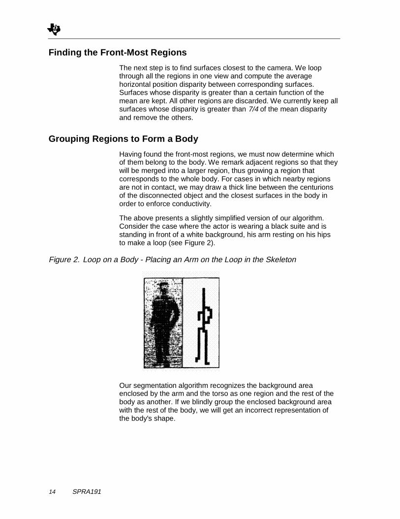
The above presents a slightly simplified version of our algorithm.Consider the case where the actor is wearing a black suite and isstanding in front of a white background, his arm resting on his hipsto make a loop (see Figure 2).
Figure 2. Loop on a Body - Placing an Arm on the Loop in the Skeleton
Our segmentation algorithm recognizes the background areaenclosed by the arm and the torso as one region and the rest of thebody as another. If we blindly group the enclosed background areawith the rest of the body, we will get an incorrect representation ofthe body's shape.

Introducing A Vision-Based Posture Tracking System Using the TMS320C40 DSP 15
The solution is to impose an additional criterion that must be metbefore a region is grouped with the body; that is, the region may notbe grouped along if other regions enclose it. The condition issufficient to preserve the correct shape of the body but adds anannoying restriction for which we have not yet reconciled: the inputimage of the body should not have a region enclosed within a largerregion. If it does, the inscribed region will be dropped out after thisstage and an artificial loop will be created in an inappropriate place.
Consider, for example, an actor in a black body suit boasting a largered dot on the chest. The red dot will appear as a hole in the body'sfinal bitmap, completely confusing subsequent stages in theprocessing. Notice that this restriction doesn't apply to cases wherethe actor is wearing short sleeved or even striped shirts
Skeletonization
The skeletonization phase takes the bitmap of the body and returnsa skeleton consisting of a set of pixels representing the structure ofthe posture in a compact form. We introduce this stage bypresenting some terms used in this application brief.
NOTE: These definitions apply to our work only and may differfrom definitions applied by others.
Member A component of pixels 1 pixel thick connectedwith adjacency k=4. The final skeleton has onemember for each arm and leg, one for thespine, and one for the head. A member cannotbe self-intersecting; that is, it should beimpossible to draw a non-nil path that beginsand ends on the same pixel without visitingother pixels in the member no more than once.
One-Pixel-ThickMember
A member in which every pixel is critical
Skeleton A collection of connected members. Byconnected, we mean that from any member, it ispossible to use k=4 adjacency to reach anyother member in the skeleton.
Critical Member A member is critical if its removal will cause theskeleton to become disconnected.
Cyclic Member A non-nil path that starts and ends on the samemember without visiting other members morethan once. This is not a strict definition but aproperty of cyclic members important to us.
Joint Pixel A pixel in the skeleton shared by two or moremembers. Critical and cyclic members must bedelimited by two joint pixels.

16 SPRA191
Extremity Pixel A member pixel with only one neighbor. Seethe discussion below for details.
The implementation of our skeletonizer requires a test for one pixelthickness, so we present an algorithm that efficiently determineswhether a member is one pixel thick. We examine each of its pixelsand its surrounding eight neighbors as a 3x3 binary matrix.
Conceptually. if a k=4 path exists within the 3x3 matrix through thecenter pixel from one edge of the matrix to any other edge, that pixelis critical only if there are no alternative k:=4 paths which don’t gothrough the center pixel. Figure 2 depicts some cases of interest.
Figure 3. Local 3x3 Matrix Used to Determine Criticality of a Point in a Member
1 2 3
4 5 6
7 8 9
b
a
e
c f
d
Notes: a. Our numbering conventionb. In this case, the center pixel is critical because 856 is the only path
between 8 and 6.c. In this case, 5 is not critical because an alternate path 896 exists
between 8 and 6.d. 5 is again not critical because 8741236 is an alternate path for 856.
(Notice that three other paths exist with alternate paths.)e. Another case where 5 is critical.f. Non-critical 5.

Introducing A Vision-Based Posture Tracking System Using the TMS320C40 DSP 17
Armed with these definitions and criteria, the inner workings of theskeletonizer become easy to understand. The main step in thisstage is to successively erode the contour of the body, discardingnon-critical edge points until the remaining connected component isone pixel thick.
We do not erode center pixels that are not involved in any paths intheir local 3x3 matrix since they represent extremity pixels and areneeded for our stopping case. Eroding extremity pixels causes theskeleton to eventually diminish into one single pixel and disappearafter one final iteration.
The medial axis we obtain contains artifact members in addition tothe desired limb members. To augment the problem, the medial axisis also extremely sensitive to fluctuations around the contour of thebody and may produce radically different artifacts with the slightestchange in the contour. We therefore precede the skeletonizationwith a smoothing algorithm and follow it with a cleanup procedure.
The smoothing step consists of performing a single pass around theedge of the body to remove extremity pixels. Although this stepdoesn't prevent extraneous members from being generated, it helpsensure that they will not be as pronounced as the legitimatemembers.
The cleanup stage consists of decomposing the skeleton intomembers classified as limbs, critical members, or cyclic members.We can show that our erosion technique produces no cyclicmembers if the original bitmap has no holes. Since the segmentationstage guarantees that holes are produced only for looping limbs, weknow that cycles in the skeleton must correspond to limbs andtherefore must not be removed.
Furthermore, since we know that the skeleton must be connected,critical members cannot be removed either. Thankfully, the onlycritical members our erosion technique can create are those whichconnect limbs together.
The only such member in the case of the human body is the spine.Detecting the skeletal artifacts then becomes a tractable problem:artifact members can manifest themselves as only non-critical, non-cyclic members, or what we call floating members. To clean up theskeleton then, we simply remove the floating members one by oneuntil there are no more than six limbs (head, arms, legs, and spire).All free members and some circular members contribute to thenumber of limbs. The only circular members that do not contribute tothe count are redundant parts of the spine.
18 SPRA191
Member Identification
We have yet to identify the limbs. If we assume that the body is rightside up, the upper part of the spine joins three limbs (the head andthe arms) and the lower part connects only the two legs. We caneasily discern the head from the arms based on length. We handlecases separately where the arms loop to the hip. We have notprovided provisions for determining whether the body is upsidedown, since our motion history engine will be able to provide us withthat information once it is implemented.
Fitting
The final step is to fit consecutive and adjacent lines to each limband to output the coordinates of the endpoints of these lines.Specifically, for each remaining limb, we would like to fit consecutivelines that share a common endpoint and a length ratio similar to thatof the corresponding human limb. For each member, we determinethe line parameters that minimize an energy function. This is basedon the similarity of the ratio of the lengths of the line and the ratio ofbody members, and the least mean square error of the fit to thepoints of the member.
Since the stereo information is only used in identifying the front-mostregion, it is easy to replace it with something simpler for caseswhere the background can easily be separated from the body. Afeasible segmentation approach is to store the background imagebefore a human enters the scene, and then simply subtract thisimage from subsequent input frames.
Subtraction is simple and efficient, but poses several limitations onthe scene. First, there must be a high contrast between the bodyand the background. Complications arise if the actor happens towalk in front of a region of the wall that bears the same colors as theactor's clothing. The camera must also be of very high quality, as itmust produce the exact same pixels after every frame.
The quality of the camera won' t matter, however, if the lightingconditions aren't perfect. Older fluorescent lights flicker noticeably,perturbing the static regions of the background. Remember also thatwith a stereo setup, the operator has the ability to pan the cameraand follow the actor around the scene. Monoscopic setups can'tprovide this luxury. Although filtering can solve a few of these typesof problems, most of them cannot be remedied so easily.

Introducing A Vision-Based Posture Tracking System Using the TMS320C40 DSP 19
Support Software
We built a development environment for our multiprocessor tofacilitate our implementation tasks. Since UNIX is the preferreddevelopment platform for most serious research work, we wrotevarious pieces of support software, including
� Our own C40 network boot loader
� Linux drivers for various C40 boards
� Sophisticated configuration package for C40s providingconfiguration inheritance
� Profiler to identify bottlenecks in our software
� Worm-router for message passing
� Port of the ANSI C studio library
� Microkernel based on our own multithreading package.
We plan to develop additional pieces of system software for theC40. One of our goals is to extend our microkernel to allow us tosimply define logical stages in a pipeline and let the systemdynamically decide at run-lime how to distribute the tasks among theprocessors in the network. This would eliminate the typical profile-edit-compile cycle to which we have become accustomed in low-level parallel processing development.

20 SPRA191
Further Work
We must add several new features and make a few changes beforePredator can become a marketable tool.
We have not yet fully designed the occlusion-reasoning engine.Predator requires multiple cameras to be installed on the scene.Now the actor must assume simpler poses. As a holdover, weprovide a simple module capable of making use of skeletons frommultiple views. It outputs the most coherent set of joint informationprovided to it by the pipeline corresponding to each view. We havebegun designing a more sophisticated module.
The use of motion history is another feature that could benefitPredator in terms of reliability. Our system currently makes almostno use of previously gathered data. Hence, it cannot benefit from theadded accuracy and speed that could be gained from its previousresults. Known physical constraints on a human body can be usedto prune the number of possible poses a body can take after aprevious pose. Presently, we make use of previous body locationsand perform our segmentation in only a small region of the Image.
We've considered using multi-resolution processing in our visionalgorithm to further increase efficiency. We can take advantage ofthe fact that every part of the scene doesn't require the sameamount of attention. As mentioned above, we already takeadvantage of the fact that only image regions corresponding to thehuman body will be passed further up the pipeline. Segmentation isperformed only in regions where the body is likely to be located.Other stages of the pipeline can take advantage of the fact thatsome regions of the image are more important than others.
We would also like to more closely couple the skeIetonization andthe segmentation algorithms for added robustness. Knowledge ofthe skeleton may prove to be useful in performing segmentation.
In general, we would like to make our system more conscious of thework it has already performed. By making better use of feedback,we hope to improve both efficiency and accuracy.

Introducing A Vision-Based Posture Tracking System Using the TMS320C40 DSP 21
Conclusion
We have introduced Predator, a vision-based posture trackingsystem. Predator takes as input video footage of a human actor andproduces a stream of joint position information representing theposition of the actor’s limbs over time. Our design goal was to buildan unintrusive system to analyze the video data in real time withoutrequiring the user to wear any special gear or undergo any otherinitialization steps.
22 SPRA191
Team Background
Jitendra Malik is a professor of computer science at UC Berkeley.He is the head of the UC Berkeley vision group, which is heavilyinvolved in the California PATH project. PATH aims at improving thehighways of tomorrow through technology. The UC Berkeley visiongroup has already implemented two major components of the PATHproject on C40’s. One project constitutes the attitude control systemfor an autonomous car. The other involves building a device to beplaced at every city road intersection to replace the loop-detectortechnology employed in traffic control today. We have hopes ofproducing a reliable C40-based system within a year. The federalgovernment has determined that computer vision is the preferredtechnology on which the roadways of the future should be based.Our group is receiving $1,000,000 per year from the federalgovernment to pursue our research.
Ali Rahimi is a third year undergraduate majoring in electricalengineering and computer science, He is a member of the computervision group at UC Berkeley and conducts his research underProfessor Malik. His research focus is vision-based tracking andoperating system design. Part of his research in the UCB RoboticsLab involves implementing real-time vision systems on a customC40 platform.
Michael Shilman is a fourth year UCB undergraduate majoring inelectrical engineering and computer science. His research interestsfocus on virtual environments and next-generation user interfaceperipherals as they relate to CAD. The Berkeley CAD group isresponsible for some of today’s most widely used circuit design andDSP tools (Spice and Ptolemy among others). His role in this projectconsisted of building a sample client application that demonstratesour system.


