
Precise and Low-Cost GNSS Positioning for Mini-Dronescnfgg.eu/pdf/G2_2015/Mohamed SAHMOUDI.pdf ·...
39
Precise and Low-Cost GNSS Positioning for Mini-Drones Mohamed SAHMOUDI & Raghuveer KASARANENI TESA / ISAE-SUPAERO G2 Conference, OMP, Toulouse 17 th November, 2015
Transcript of Precise and Low-Cost GNSS Positioning for Mini-Dronescnfgg.eu/pdf/G2_2015/Mohamed SAHMOUDI.pdf ·...

Precise and Low-Cost GNSS Positioning for Mini-Drones
Mohamed SAHMOUDI & Raghuveer KASARANENI
TESA / ISAE-SUPAERO
G2 Conference, OMP, Toulouse
17th November, 2015

OUTLINE� Basics of GNSS Measurements Errors for PrecisePositioning
� Basics of RTK and Ambiguity Solution
� Real-time Implementation for UAVs
� Results from DROTEK and TESA COPNAV Project
� Conclusions

Needs of High Precision
� For navigation in self-driving vehicles.
Vehicles can be moved closer to each other saving fuel, time and money.
� In auto-piloted drones for package delivery.
No need of human operator and with high resolution predetermined air path ways can be used, which reduces the risk of collisions.
� In agricultural equipment.
Use of machinery, even when the crops are closely placed results in more produce in lesser area.
� Many other applications such as land surveying, geo-tagging, etc.

Limitations of Existing GNSS Receivers
� Commercially available off the shelf receivers’ used for civilian purposes usually have an accuracy of 3m.
� High precision receivers are very expensive to be used widely.
� The size of the existing high precision receiver setup are too big to be used on drones.

Objectives� Development of receiver setup with high precision : < 10 cm.
� The receiver system should be small enough to be placed on drones.
� Cost of the total system should be as low as possible (< 300€).
� Components used should be readily available in market.
� The total setup should be easy to manufacture and use.

Cost and Size Constraints
� Low cost receivers can only receive L1 carrier satellite signals.
� Geodetic grade antennas are expensive to use.
� Patch antennas are of ideal size for use on drones.
� Receiver module must be small in size and low on power consumption.

Available methods to get higher accuracy.PRECISE POINT POSITIONING [PPP]
Use of precise satellite ephemeris and atmosphere models broadcasted over internet.
This method is known to give an accuracy of 50 cm with low cost equipment.
DIFFERENTIAL GPS – REAL-TIME KINEMATIC [DGPS-RTK]
Use of a base station receiver with known position. Using the measurements of base and rover receivers, the accurate position is calculated.
Latest advancements in components and software make it feasible to obtain < 10 cm accuracy under given conditions.

Building Prototype by DROTEK
� Components used in the experimental setup.

DGPS-RTK Setup Block Diagram

Ublox NEO – M8T Receiver ModuleGPS + GLONASS measurements can be output at up to 5Hz frequency according to datasheet.
In a clear sky environment, can give a CNO ratio of >35 dB with a patch antenna itself.
Ability to give half-cycle ambiguity resolved phase measurements.
Output messages : NMEA + SFRBX + RAWX� NMEA – PVT measurements.
� SFRBX – Satellite broadcasted navigation messages.
� RAWX – Carrier phase, Doppler frequencies and pseudorange measurements.
With suppression of NMEA measurement frequency can be increased beyond 5 Hz.

Changes to the receiver boardXL design to XXL design
�Size of the ground plane from 4 x 4 cm to 8 x 8 cm.
�Removed the GNSS front-end module.
�Ublox module placed close to the antenna pin.
�Shielded RF signal circuit.

The deviation maps (with same scale) of data collected with XL design (left) and XXL design (right) receiver modules.Data collected for 7 minutes simultaneously with both boards.

Testing the effect of board size on directivityTable and picture.
60° inclination towards
north
30° inclination
towards north 0° inclination
xl_60 xxl_60 xl_30 xxl_30 xl xxl Units
Standard Deviation of
X ECEF 1.2 0.99 1.6 1.1 2.25 1.14 m
Standard Deviation of
Y ECEF 1.08 0.43 1.2 0.38 0.89 0.6 m
Standard Deviation of
Z ECEF 2.3 1.07 1.5 0.98 1.28 1.19 m
Average HDOP 0.8 0.8 0.7 0.7 0.7 0.7 DOP
Average VDOP 1 1 1 0.9 0.9 0.9 DOP
Average PDOP 1.3 1.2 1.2 1.2 1.2 1.2 DOP
Average Sats tracked 18 19 20 20 21 20 SVs
Average C/No per SV 34.07 36.28 31.41 35.08 32.5 36.3 dB Hz
*Data collected for >12 minutes
HDOP – Horizontal Dilution Of Precision
VDOP – Vertical Dilution Of Precision
PDOP – Position Dilution Of Precision
DOP – Dilution Of Precision
SV – Satellite Vehicle
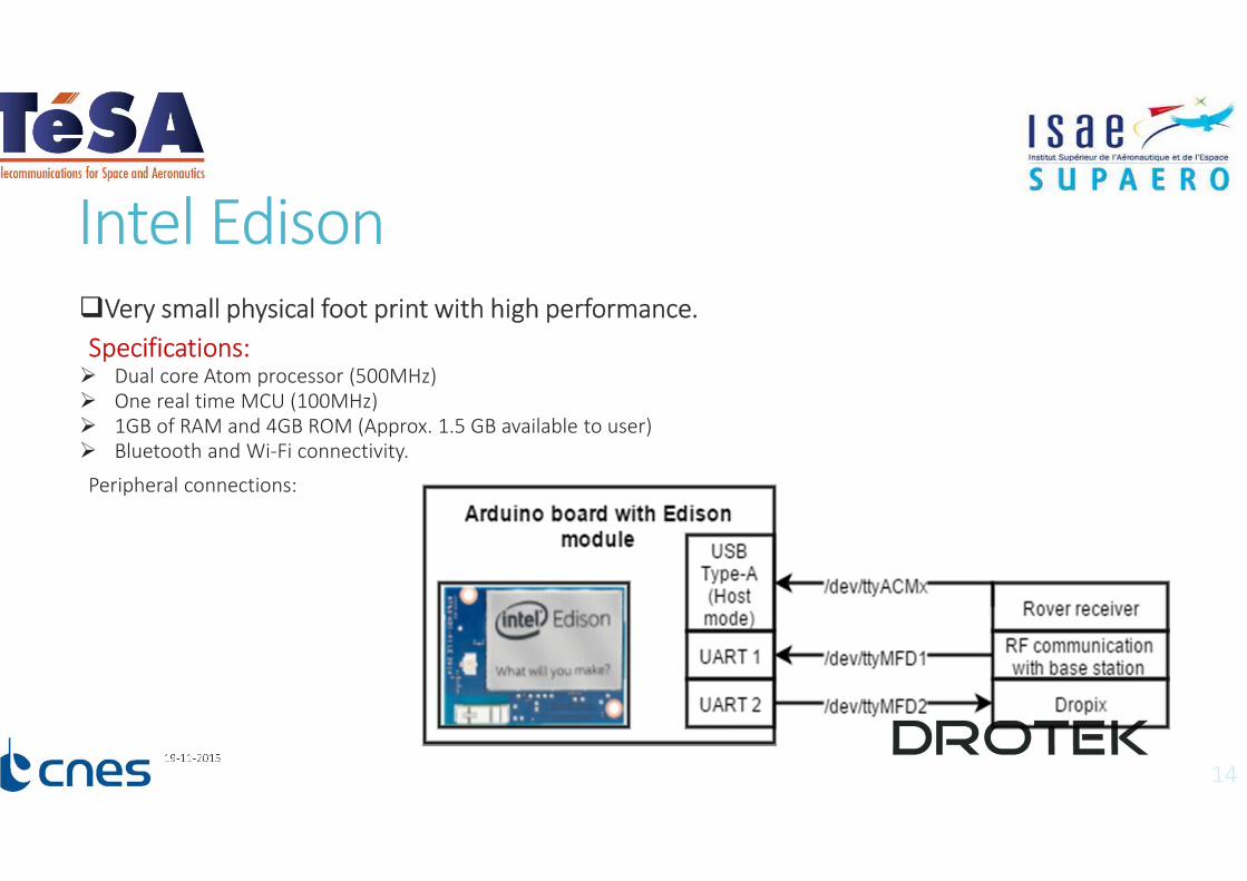
Intel Edison�Very small physical foot print with high performance.
Specifications:� Dual core Atom processor (500MHz)
� One real time MCU (100MHz)
� 1GB of RAM and 4GB ROM (Approx. 1.5 GB available to user)
� Bluetooth and Wi-Fi connectivity.
Peripheral connections:
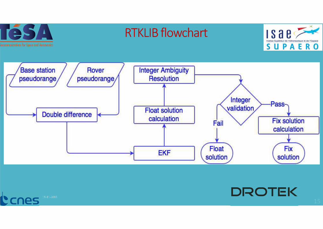
RTKLIB flowchart

Changes to RTKLIB
�Interface with Arducopter control system.
�MRAA library usage for Intel Edison pin configuration.
�Use of GPIOs for easy user interface.
�Sending location data to base station for display.

DROTEK break out boardMinimum bridges.
Scope for future development.

Usage of MKL library and comparison of CPU usage.
RF Communication
�433 MHz [3DR radio] RF communication.
Approx. 3 km range at baud rate of 19200 bps.
�433 MHz LoRa [Dorji] RF communication.
Low baud rate of 12500 bps and range not verified.
Need faster modulation components.
� The breakout board supports 3G/4G LTE modem connection via USB.

Plot of solutions from base station data at 1 Hz (orange) and 10 Hz (green)

AntennaeThe whip style antenna gave better RSSI (Received Signal Strength Indication) compared to others.

Comparison of DGPS (yellow) and single (orange) solutionsOpen sky (left), Tree cover (middle) and Buildings (right)

Comparison of DGPS (blue) and NRCAN PPP (red) solutionsOpen sky (left), Tree cover (middle) and Buildings (right)

Specifications*Price with single feed passive
patch antenna.
For dual feed active antenna, the
price is between 200€ - 250 €.
Cost of production 155 €*
Rover station size 8 cm x 8cm x 1.5 cm
Weight 80 g
Peak power
consumption< 1 W
Precision 30 cm
Developped RTK Solution

Comparison of Ublox + Tallysman (green) with Septentrio + Novatel (orange).Open sky view and vehicle not moving.
5 cm scale

Comparison of Ublox + Tallysman (orange) with Septentrio + Novatel (yellow).Open sky view and moving vehicle
10 m scale

Comparison of Ublox + Tallysman (orange) with Septentrio + Novatel (yellow).Under foliage and moving vehicle
5 m scale
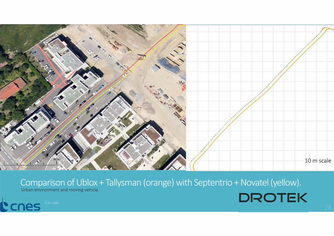
Comparison of Ublox + Tallysman (orange) with Septentrio + Novatel (yellow).Urban environment and moving vehicle.
10 m scale
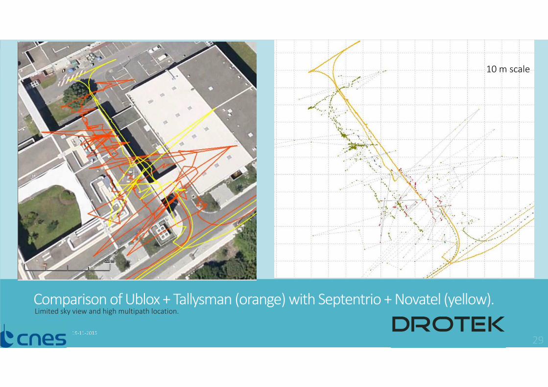
Comparison of Ublox + Tallysman (orange) with Septentrio + Novatel (yellow).Limited sky view and high multipath location.
10 m scale

More results : Rover & Base Single Frequency L1
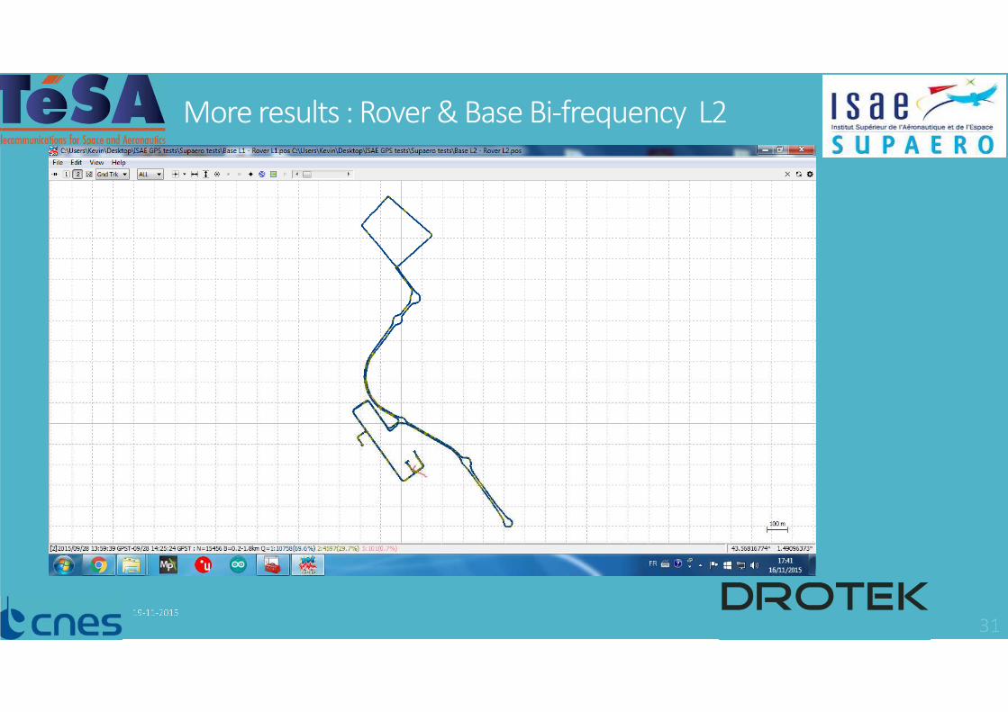
More results : Rover & Base Bi-frequency L2

More results : Rover & Base Bi-frequency L2

More results : Single Frequency v.s. Bifrequency

Results : Single Frequency v.s. Bifrequency Zoom

Titre de la réunion - Auteurs - Date
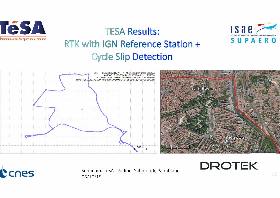
Séminaire TéSA – Sidibe, Sahmoudi, Paimblanc –
06/10/15
Séminaire TéSA – Sidibe, Sahmoudi, Paimblanc –
06/10/15
Conclusions�A Low-Cost solution of less than 200€ is prototyped by DroTek for Drones and other applications
�Bi-frequency solution is clearly better than signle frequency solution
� In open sky view and when the vehicle is not moving, the positioning is comparable with a geodetic grade receiver.
� Improvement of RTKLIB is achieved in the context of the TESA PTP COPNAV project.
�Under limited sky view and multipath prone environment, the errors are not compensated � other works will try to resolve these problems
�The offset in position during vehicle movement is to be analyzed.